technical book steam generators um - cannon bono · feedwater quality requirements for best...
TRANSCRIPT
FL
AS
H C
OIL
ST
EA
M G
EN
ER
AT
OR
S U
NI-
MA
TIC
Technical Book Steam Generators UM

2
1. General Information
2. Competitive Advantages
3. Technical Specifications
4. P&ID
5. Dimensions and Connections
6. Generator Layout
7. Installation
8. Maintenance
9. Scope of Supply
10. Appendix 1. Fuel consumption calculation
11. Appendix 2. Thermodynamic characteristics of
saturated steam
FLASH COIL STEAM GENERATORS UNI-MATIC
3
4
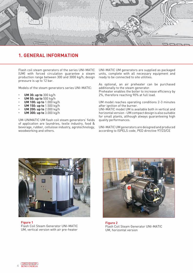
Flash coil steam generators of the series UNI-MATIC (UM) with forced circulation guarantee a steam production range between 300 and 3000 kg/h; design pressure is up to 12 bar.
Models of the steam generators series UNI-MATIC:
• UM 30: up to 300 kg/h• UM 50: up to 500 kg/h• UM 100: up to 1.000 kg/h• UM 150: up to 1.500 kg/h• UM 200: up to 2.000 kg/h• UM 300: up to 3.000 kg/h
UM-UNIMATIC UM flash coil steam generators’ fields of application are laundries, texile industry, food & beverage, rubber, cellulose industry, agrotechnology, woodworking and others.
UNI-MATIC UM generators are supplied as packaged units, complete with all necessary equipment and ready to be connected to site utilities.
As optional, an air preheater can be purchased additionally to the steam generator. Preheater enables the boiler to increase efficiency by 2%, therefore reaching 90% at full load.
UM model reaches operating conditions 2-3 minutes after ignition of the burner. UNI-MATIC model UM is available both in vertical and horizontal version - UM compact design is also suitable for small plants, although always guaranteeing high quality performances.
UNI-MATIC UM generators are deisgned and produced according to ISPELS code, PED directive 97/23/CE
Figure 1Flash Coil Steam Generator UNI-MATIC UM, vertical version with air pre-heater
1. GENERAL INFORMATION
Figure 2Flash Coil Steam Generator UNI-MATIC UM, horizontal version
5
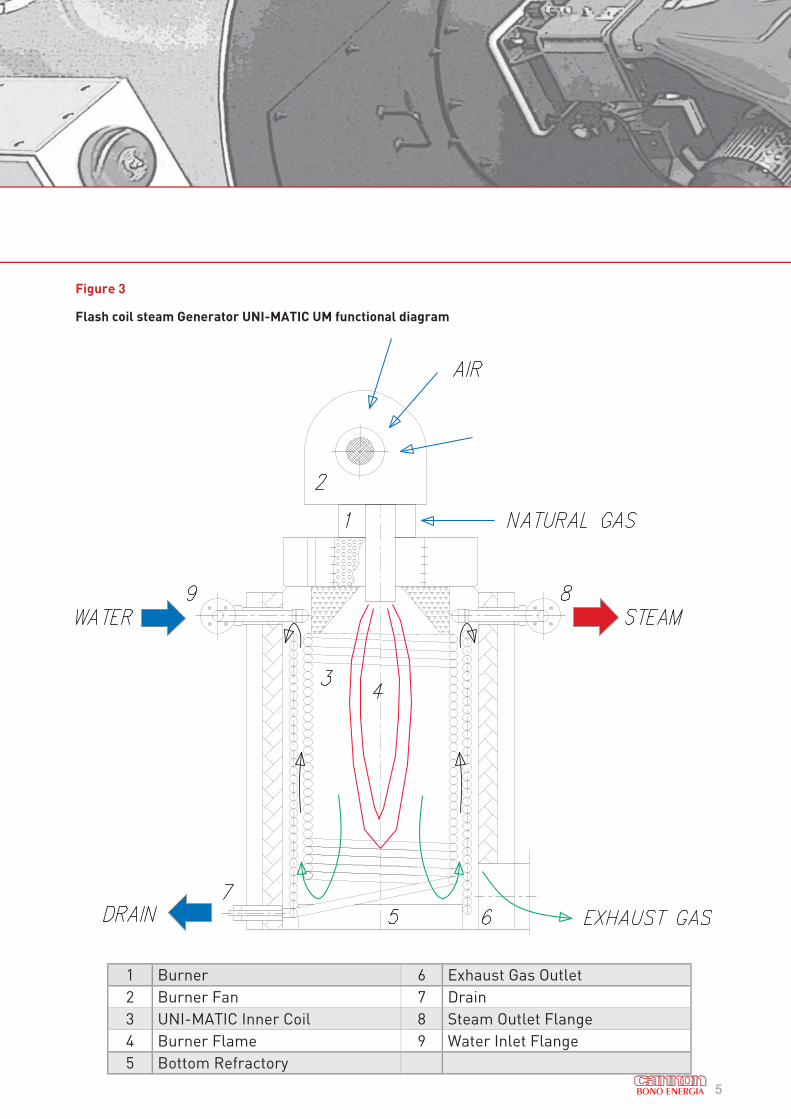
1 Burner 6 Exhaust Gas Outlet
2 Burner Fan 7 Drain
3 UNI-MATIC Inner Coil 8 Steam Outlet Flange
4 Burner Flame 9 Water Inlet Flange
5 Bottom Refractory
Figure 3
Flash coil steam Generator UNI-MATIC UM functional diagram
6
2. COMPETITIVE ADVANTAGES
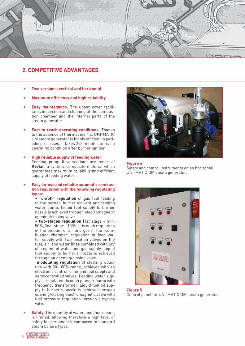
Figure 4 Safety and control instruments on an horizontal UNI-MATIC UM steam generator.
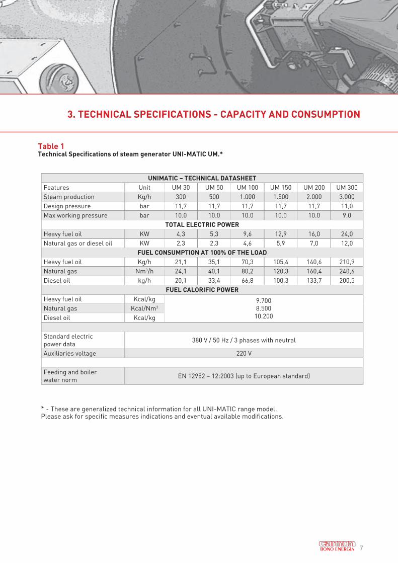
Figure 5Control panel for UNI-MATIC UM steam generator.
• Two versions: vertical and horizontal
• Maximum efficiency and high reliability
• Easy maintenance. The upper cover facili-tates inspection and cleaning of the combus-tion chamber and the internal parts of the steam generator.
• Fast to reach operating conditions. Thanks to the absence of thermal inertia, UNI-MATIC UM steam generator is highly efficient in peri-odic processes. It takes 2÷3 minutes to reach operating condition after burner ignition.
• High reliable supply of feeding water. Feeding pump flow sections are made of
Kevlar, a syntetic composite material which guarantees maximum reliability and efficient supply of feeding water.
• Easy-to-use and reliable automatic combus-tion regulation with the following regulating types:
• “on/off” regulation of gas fuel feeding to the burner, burner air vent and feeding water pump. Liquid fuel supply to burner nozzle is achieved through electromagnetic opening/closing valve.• two-stages regulation (1st stage - min. 50%, 2nd stage - 100%), through regulation of the amount of air and gas in the com-bustion chamber, regulation of feed wa-ter supply with two-position valves on the fuel, air and water lines combined with on/off regime of water and gas supply. Liquid fuel supply to burner’s nozzle is achieved through an opening/closing valve. modulating regulation of steam produc-tion with 30-100% range, achieved with an electronic control of air and fuel supply and servocontrolled valves. Feeding water sup-ply is regulated through plunger pump with frequency transformer. Liquid fuel oil sup-ply to burner’s nozzle is achieved through opening/closing electromagnetic valve with fuel pressure regulation through a bypass valve.
• Safety. The quantity of water, and thus steam, is limited, allowing therefore a high level of safety for personnel if compared to standard steam boilers types.
7
3. TECHNICAL SPECIFICATIONS - CAPACITY AND CONSUMPTION
Table 1Technical Specifications of steam generator UNI-MATIC UM.*
UNIMATIC – TECHNICAL DATASHEET
Features Unit UM 30 UM 50 UM 100 UM 150 UM 200 UM 300
Steam production Kg/h 300 500 1.000 1.500 2.000 3.000
Design pressure bar 11,7 11,7 11,7 11,7 11,7 11,0
Max working pressure bar 10.0 10.0 10.0 10.0 10.0 9.0
TOTAL ELECTRIC POWER
Heavy fuel oil KW 4,3 5,3 9,6 12,9 16,0 24,0
Natural gas or diesel oil KW 2,3 2,3 4,6 5,9 7,0 12,0
FUEL CONSUMPTION AT 100% OF THE LOAD
Heavy fuel oil Kg/h 21,1 35,1 70,3 105,4 140,6 210,9
Natural gas Nm3/h 24,1 40,1 80,2 120,3 160,4 240,6
Diesel oil kg/h 20,1 33,4 66,8 100,3 133,7 200,5
FUEL CALORIFIC POWER
Heavy fuel oil Kcal/kg 9.700
8.500
10.200
Natural gas Kcal/Nm3
Diesel oil Kcal/kg
Standard electric
power data380 V / 50 Hz / 3 phases with neutral
Auxiliaries voltage 220 V
Feeding and boiler
water normEN 12952 – 12:2003 (up to European standard)
* - These are generalized technical information for all UNI-MATIC range model. Please ask for specific measures indications and eventual available modifications.
8
3. TECHNICAL SPECIFICATIONS - THERMAL EFFICIENCY
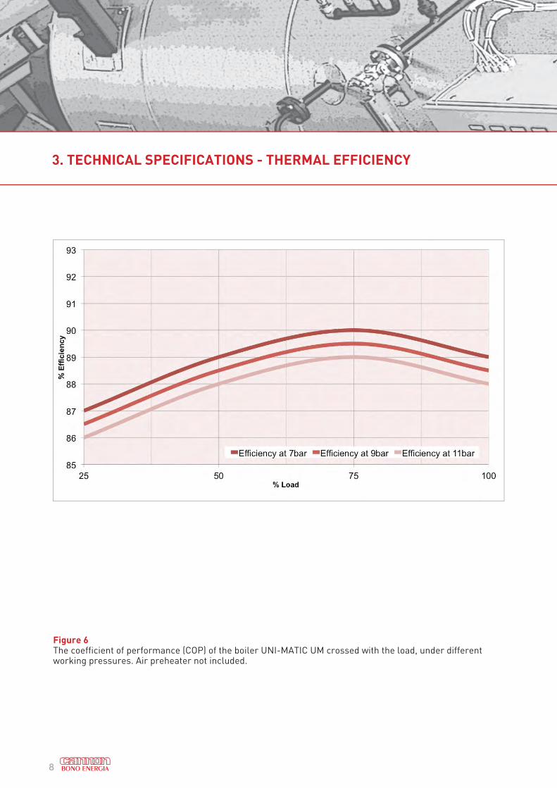
Figure 6The coefficient of performance (COP) of the boiler UNI-MATIC UM crossed with the load, under different working pressures. Air preheater not included.
9
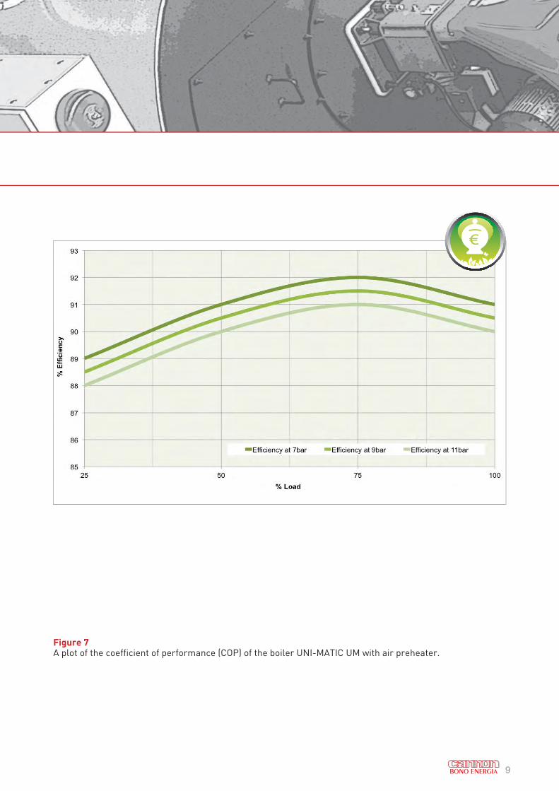
Figure 7A plot of the coefficient of performance (COP) of the boiler UNI-MATIC UM with air preheater.
10
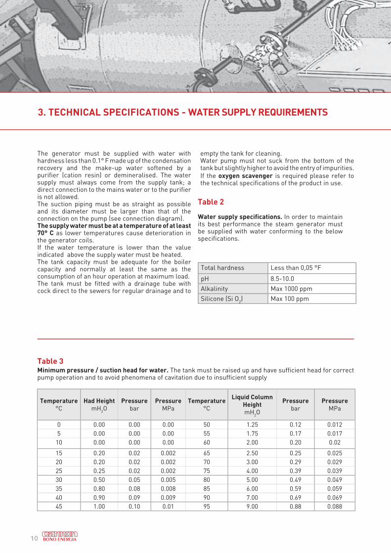
The generator must be supplied with water with hardness less than 0.1° F made up of the condensation recovery and the make-up water softened by a purifier (cation resin) or demineralised. The water supply must always come from the supply tank; a direct connection to the mains water or to the purifier is not allowed.The suction piping must be as straight as possible and its diameter must be larger than that of the connection on the pump (see connection diagram).The supply water must be at a temperature of at least 70° C as lower temperatures cause deterioration in the generator coils.If the water temperature is lower than the value indicated above the supply water must be heated.The tank capacity must be adequate for the boiler capacity and normally at least the same as the consumption of an hour operation at maximum load.The tank must be fitted with a drainage tube with cock direct to the sewers for regular drainage and to
empty the tank for cleaning.Water pump must not suck from the bottom of the tank but slightly higher to avoid the entry of impurities.
If the oxygen scavenger is required please refer to the technical specifications of the product in use.
Total hardness Less than 0,05 °F
pH 8.5-10.0
Alkalinity Max 1000 ppm
Silicone (Si O2) Max 100 ppm
Table 2
Water supply specifications. In order to maintain its best performance the steam generator must be supplied with water conforming to the below specifications.
Table 3Minimum pressure / suction head for water. The tank must be raised up and have sufficient head for correct pump operation and to avoid phenomena of cavitation due to insufficient supply
Temperature
°C
Had Height
mH2O
Pressure
bar
Pressure
MPa
Temperature
°C
Liquid Column
Height
mH2O
Pressure
bar
Pressure
MPa
0 0.00 0.00 0.00 50 1.25 0.12 0.012
5 0.00 0.00 0.00 55 1.75 0.17 0.017
10 0.00 0.00 0.00 60 2.00 0.20 0.02
15 0.20 0.02 0.002 65 2.50 0.25 0.025
20 0.20 0.02 0.002 70 3.00 0.29 0.029
25 0.25 0.02 0.002 75 4.00 0.39 0.039
30 0.50 0.05 0.005 80 5.00 0.49 0.049
35 0.80 0.08 0.008 85 6.00 0.59 0.059
40 0.90 0.09 0.009 90 7.00 0.69 0.069
45 1.00 0.10 0.01 95 9.00 0.88 0.088
3. TECHNICAL SPECIFICATIONS - WATER SUPPLY REQUIREMENTS
11
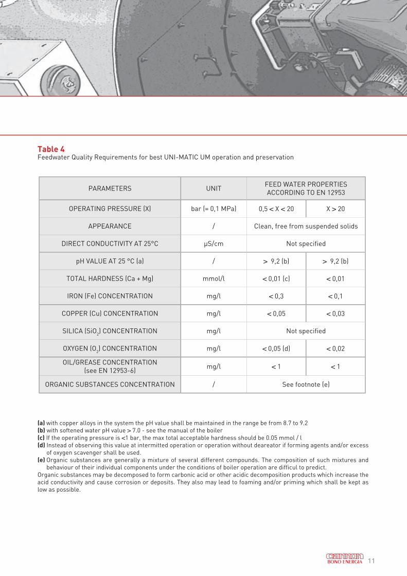
Table 4Feedwater Quality Requirements for best UNI-MATIC UM operation and preservation
(a) with copper alloys in the system the pH value shall be maintained in the range be from 8.7 to 9.2
(b) with softened water pH value > 7.0 - see the manual of the boiler
(c) If the operating pressure is <1 bar, the max total acceptable hardness should be 0.05 mmol / l
(d) Instead of observing this value at intermitted operation or operation without deareator if forming agents and/or excess
of oxygen scavenger shall be used.
(e) Organic substances are generally a mixture of several different compounds. The composition of such mixtures and
behaviour of their individual components under the conditions of boiler operation are difficul to predict.
Organic substances may be decomposed to form carbonic acid or other acidic decomposition products which increase the
acid conductivity and cause corrosion or deposits. They also may lead to foaming and/or priming which shall be kept as
low as possible.
PARAMETERS UNIT FEED WATER PROPERTIES
ACCORDING TO EN 12953
OPERATING PRESSURE (X) bar (= 0,1 MPa) 0,5 < X < 20 X > 20
APPEARANCE / Clean, free from suspended solids
DIRECT CONDUCTIVITY AT 25°C μS/cm Not specified
pH VALUE AT 25 °C (a) / > 9,2 (b) > 9,2 (b)
TOTAL HARDNESS (Ca + Mg) mmol/l < 0,01 (c) < 0,01
IRON (Fe) CONCENTRATION mg/l < 0,3 < 0,1
COPPER (Cu) CONCENTRATION mg/l < 0,05 < 0,03
SILICA (SiO2) CONCENTRATION mg/l Not specified
OXYGEN (O2) CONCENTRATION mg/l < 0,05 (d) < 0,02
OIL/GREASE CONCENTRATION
(see EN 12953-6)mg/l < 1 < 1
ORGANIC SUBSTANCES CONCENTRATION / See footnote (e)
12
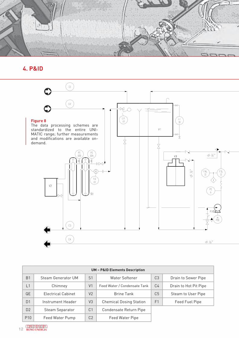
4. P&ID
UM – P&ID Elements Description
B1 Steam Generator UM S1 Water Softener C3 Drain to Sewer Pipe
L1 Chimney V1 Feed Water / Condensate Tank C4 Drain to Hot Pit Pipe
QE Electrical Cabinet V2 Brine Tank C5 Steam to User Pipe
D1 Instrument Header V3 Chemical Dosing Station F1 Feed Fuel Pipe
D2 Steam Separator C1 Condensate Return Pipe
P10 Feed Water Pump C2 Feed Water Pipe
Figure 8The data processing schemes are standardized to the entire UNI-MATIC range; further measurements and modifications are available on-demand.
13
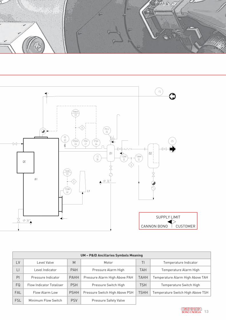
UM – P&ID Ancillaries Symbols Meaning
LV Level Valve M Motor TI Temperature Indicator
LI Level Indicator PAH Pressure Alarm High TAH Temperature Alarm High
PI Pressure Indicator PAHH Pressure Alarm High Above PAH TAHH Temperature Alarm High Above TAH
FQ Flow Indicator Totaliser PSH Pressure Switch High TSH Temperature Switch High
FAL Flow Alarm Low PSHH Pressure Switch High Above PSH TSHH Temperature Switch High Above TSH
FSL Minimum Flow Switch PSV Pressure Safety Valve
SUPPLY LIMIT
CANNON BONO CUSTOMER
14
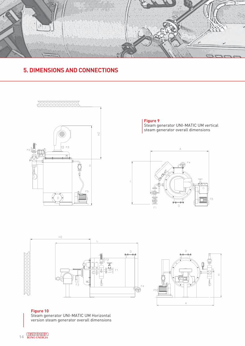
5. DIMENSIONS AND CONNECTIONS
Figure 10Steam generator UNI-MATIC UM Horizontal version steam generator overall dimensions
Figure 9Steam generator UNI-MATIC UM vertical steam generator overall dimensions
15
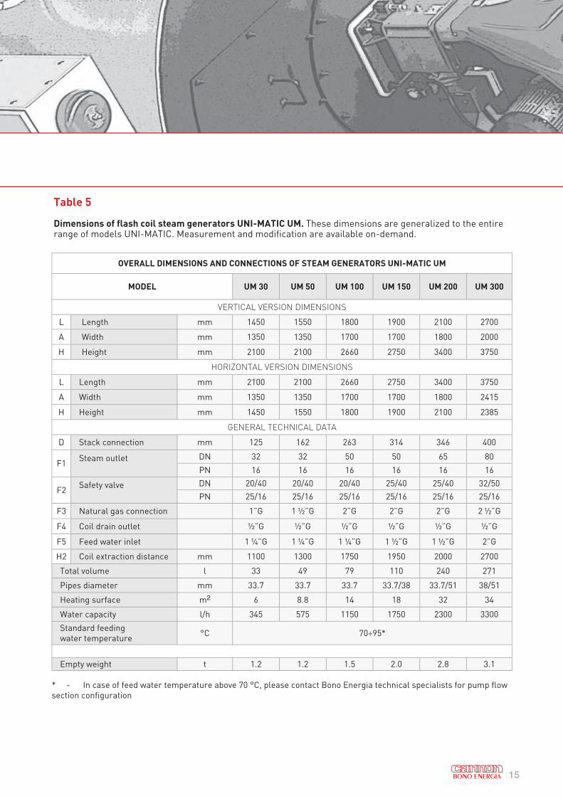
Table 5
Dimensions of flash coil steam generators UNI-MATIC UM. These dimensions are generalized to the entire range of models UNI-MATIC. Measurement and modification are available on-demand.
OVERALL DIMENSIONS AND CONNECTIONS OF STEAM GENERATORS UNI-MATIC UM
MODEL UM 30 UM 50 UM 100 UM 150 UM 200 UM 300
VERTICAL VERSION DIMENSIONS
L Length mm 1450 1550 1800 1900 2100 2700
A Width mm 1350 1350 1700 1700 1800 2000
H Height mm 2100 2100 2660 2750 3400 3750
HORIZONTAL VERSION DIMENSIONS
L Length mm 2100 2100 2660 2750 3400 3750
A Width mm 1350 1350 1700 1700 1800 2415
H Height mm 1450 1550 1800 1900 2100 2385
GENERAL TECHNICAL DATA
D Stack connection mm 125 162 263 314 346 400
F1Steam outlet DN 32 32 50 50 65 80
PN 16 16 16 16 16 16
F2Safety valve DN 20/40 20/40 20/40 25/40 25/40 32/50
PN 25/16 25/16 25/16 25/16 25/16 25/16
F3 Natural gas connection 1”G 1 ½”G 2”G 2”G 2”G 2 ½”G
F4 Coil drain outlet ½”G ½”G ½”G ½”G ½”G ½”G
F5 Feed water inlet 1 ¼”G 1 ¼”G 1 ¼”G 1 ½”G 1 ½”G 2”G
H2 Coil extraction distance mm 1100 1300 1750 1950 2000 2700
Total volume l 33 49 79 110 240 271
Pipes diameter mm 33.7 33.7 33.7 33.7/38 33.7/51 38/51
Heating surface m2 6 8.8 14 18 32 34
Water capacity l/h 345 575 1150 1750 2300 3300
Standard feeding
water temperature °C 70÷95*
Empty weight t 1.2 1.2 1.5 2.0 2.8 3.1
* - In case of feed water temperature above 70 °C, please contact Bono Energia technical specialists for pump flow
section configuration
16
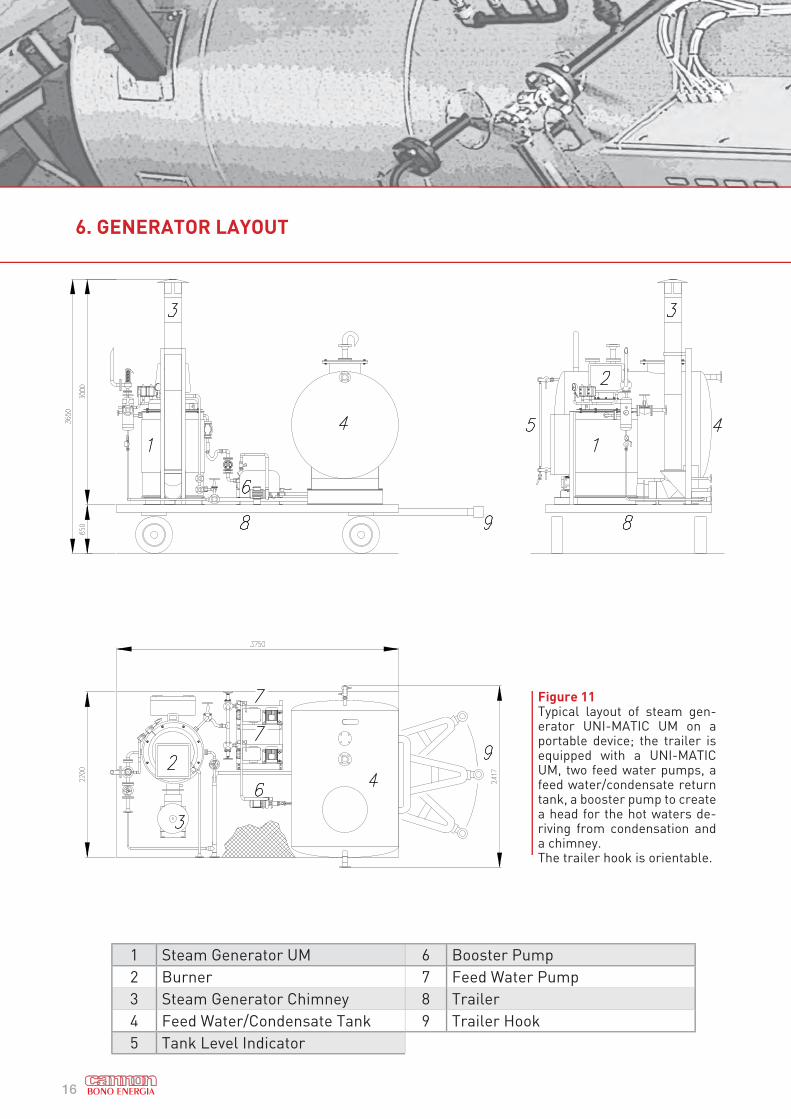
6. GENERATOR LAYOUT
Figure 11Typical layout of steam gen-erator UNI-MATIC UM on a portable device; the trailer is equipped with a UNI-MATIC UM, two feed water pumps, a feed water/condensate return tank, a booster pump to create a head for the hot waters de-riving from condensation and a chimney. The trailer hook is orientable.
1 Steam Generator UM 6 Booster Pump
2 Burner 7 Feed Water Pump
3 Steam Generator Chimney 8 Trailer
4 Feed Water/Condensate Tank 9 Trailer Hook
5 Tank Level Indicator
17
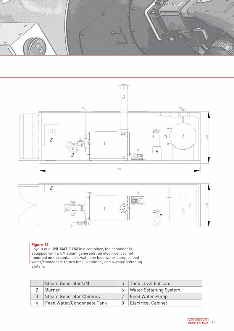
Figure 12Layout of a UNI-MATIC UM in a container; the container is equipped with a UM steam generator, an electrical cabinet mounted on the container’s wall, one feed water pump, a feed water/condensate return tank, a chimney and a water softening system.
1 Steam Generator UM 5 Tank Level Indicator
2 Burner 6 Water Softening System
3 Steam Generator Chimney 7 Feed Water Pump
4 Feed Water/Condensate Tank 8 Electrical Cabinet
18
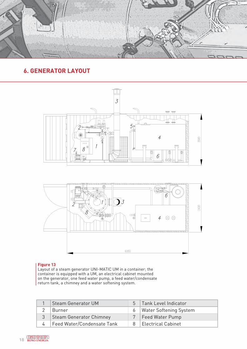
Figure 13Layout of a steam generator UNI-MATIC UM in a container; the container is equipped with a UM, an electrical cabinet mounted on the generator, one feed water pump, a feed water/condensate return tank, a chimney and a water softening system.
1 Steam Generator UM 5 Tank Level Indicator
2 Burner 6 Water Softening System
3 Steam Generator Chimney 7 Feed Water Pump
4 Feed Water/Condensate Tank 8 Electrical Cabinet
6. GENERATOR LAYOUT
19
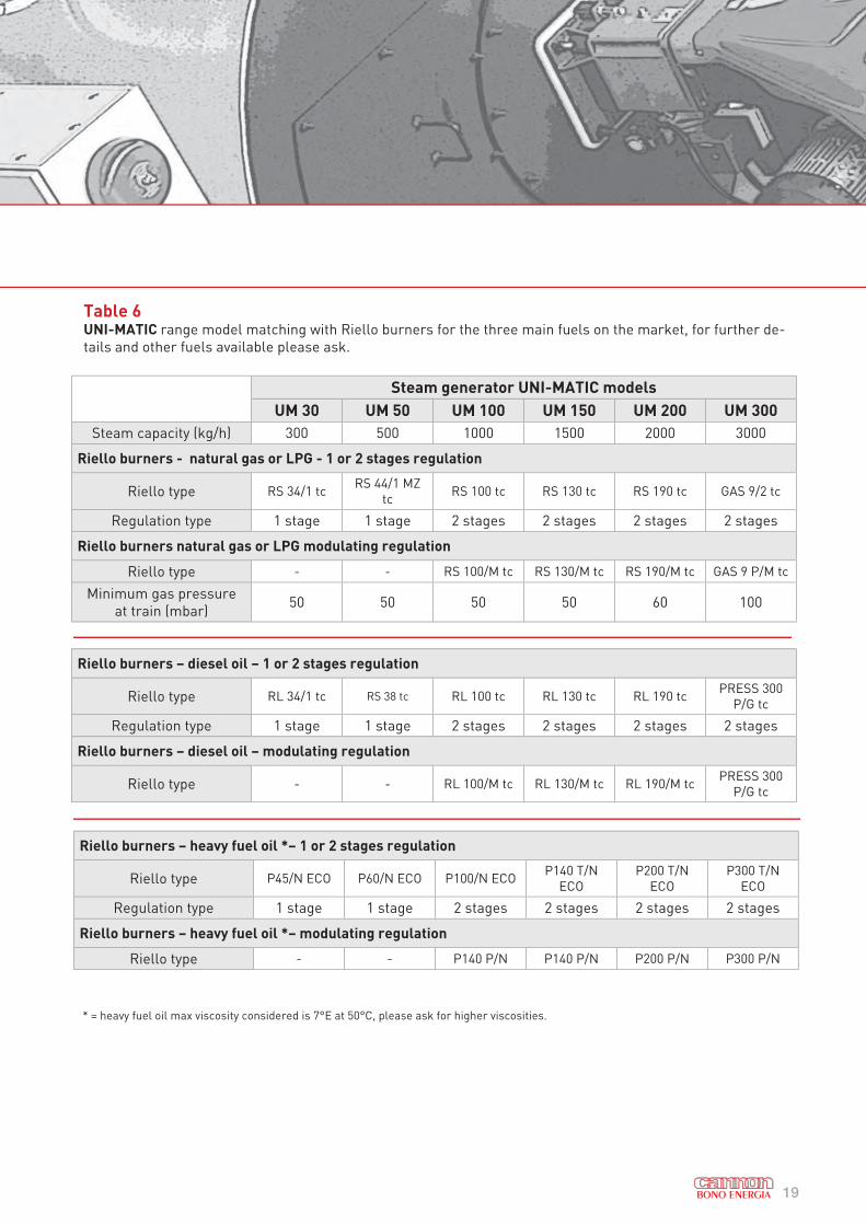
Table 6UNI-MATIC range model matching with Riello burners for the three main fuels on the market, for further de-
tails and other fuels available please ask.
Steam generator UNI-MATIC models
UM 30 UM 50 UM 100 UM 150 UM 200 UM 300
Steam capacity (kg/h) 300 500 1000 1500 2000 3000
Riello burners - natural gas or LPG - 1 or 2 stages regulation
Riello type RS 34/1 tcRS 44/1 MZ
tcRS 100 tc RS 130 tc RS 190 tc GAS 9/2 tc
Regulation type 1 stage 1 stage 2 stages 2 stages 2 stages 2 stages
Riello burners natural gas or LPG modulating regulation
Riello type - - RS 100/M tc RS 130/M tc RS 190/M tc GAS 9 P/M tc
Minimum gas pressure
at train (mbar)50 50 50 50 60 100
Riello burners – diesel oil – 1 or 2 stages regulation
Riello type RL 34/1 tc RS 38 tc RL 100 tc RL 130 tc RL 190 tcPRESS 300
P/G tc
Regulation type 1 stage 1 stage 2 stages 2 stages 2 stages 2 stages
Riello burners – diesel oil – modulating regulation
Riello type - - RL 100/M tc RL 130/M tc RL 190/M tcPRESS 300
P/G tc
Riello burners – heavy fuel oil *– 1 or 2 stages regulation
Riello type P45/N ECO P60/N ECO P100/N ECOP140 T/N
ECO
P200 T/N
ECO
P300 T/N
ECO
Regulation type 1 stage 1 stage 2 stages 2 stages 2 stages 2 stages
Riello burners – heavy fuel oil *– modulating regulation
Riello type - - P140 P/N P140 P/N P200 P/N P300 P/N
* = heavy fuel oil max viscosity considered is 7°E at 50°C, please ask for higher viscosities.
20
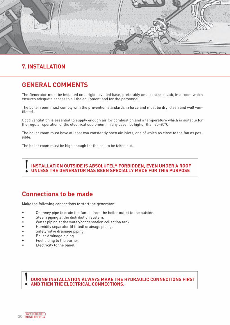
GENERAL COMMENTS
The Generator must be installed on a rigid, levelled base, preferably on a concrete slab, in a room which ensures adequate access to all the equipment and for the personnel.
The boiler room must comply with the prevention standards in force and must be dry, clean and well ven-tilated.
Good ventilation is essential to supply enough air for combustion and a temperature which is suitable for the regular operation of the electrical equipment, in any case not higher than 35-40°C.
The boiler room must have at least two constantly open air inlets, one of which as close to the fan as pos-sible.
The boiler room must be high enough for the coil to be taken out.
Connections to be made
Make the following connections to start the generator:
• Chimney pipe to drain the fumes from the boiler outlet to the outside.
• Steam piping at the distribution system.
• Water piping at the water/condensation collection tank.
• Humidity separator (if fitted) drainage piping.
• Safety valve drainage piping.
• Boiler drainage piping.
• Fuel piping to the burner.
• Electricity to the panel.
! INSTALLATION OUTSIDE IS ABSOLUTELY FORBIDDEN, EVEN UNDER A ROOF UNLESS THE GENERATOR HAS BEEN SPECIALLY MADE FOR THIS PURPOSE
! DURING INSTALLATION ALWAYS MAKE THE HYDRAULIC CONNECTIONS FIRST AND THEN THE ELECTRICAL CONNECTIONS.
7. INSTALLATION
21
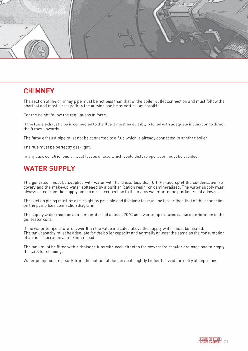
CHIMNEY
The section of the chimney pipe must be not less than that of the boiler outlet connection and must follow the shortest and most direct path to the outside and be as vertical as possible.
For the height follow the regulations in force.
If the fume exhaust pipe is connected to the flue it must be suitably pitched with adequate inclination to direct the fumes upwards.
The fume exhaust pipe must not be connected to a flue which is already connected to another boiler.
The flue must be perfectly gas-tight.
In any case constrictions or local losses of load which could disturb operation must be avoided.
WATER SUPPLY
The generator must be supplied with water with hardness less than 0.1°F made up of the condensation re-covery and the make-up water softened by a purifier (cation resin) or demineralised. The water supply must always come from the supply tank; a direct connection to the mains water or to the purifier is not allowed.
The suction piping must be as straight as possible and its diameter must be larger than that of the connection on the pump (see connection diagram).
The supply water must be at a temperature of at least 70°C as lower temperatures cause deterioration in the generator coils.
If the water temperature is lower than the value indicated above the supply water must be heated.The tank capacity must be adequate for the boiler capacity and normally at least the same as the consumption of an hour operation at maximum load.
The tank must be fitted with a drainage tube with cock direct to the sewers for regular drainage and to empty the tank for cleaning.
Water pump must not suck from the bottom of the tank but slightly higher to avoid the entry of impurities.

22
GENERATOR INSTRUMENT HEADER
The generator is fitted with an instrument header on which the following equipment is mounted:
• The safety valve of the generator• The steam on-off valve• The distribution manifold of the safety and control devices• The steam thermometer• The steam thermometer with the related gauge test tap • Condensation discharge pipe
The instrument header is also a humidity separator. In this regard kindly refer to the relevant para-graph.
During normal functioning of the generator the steam produced passes through the manifold. The manifold is thus very hot. Do not go near the manifold for any reason. THERE IS A DANGER OF BEING BURNT.
The tank must be raised up and have sufficient head for correct pump operation and to avoid phenomena
of cavitation owing to insufficient supply - refer to the table given below.
See chapter 3, table 3 for water pressure/suction head ditails.
7. INSTALLATION
Figure 14Generator instrument header
23
HUMIDITY SEPARATOR (if fitted) DRAINAGE PIPING
The continuous purge of the humidity separator condensation drainage is recommended. It is connected to the water tank so that it can be recovered by pre-heating the supply water (compatible with the maximum operat-ing temperature allowed for the pump).
In this case to avoid an excessive concentration of salts drain the tank regularly.
BOILER DRAINAGE PIPING
The boiler drainage valve must be connected directly to the hot sump with independent piping for the drainage under pressure of the coil.
The boiler drainage valve must be operated at least once a day to remove slime and deposits.
For generators in the horizontal version, the drainage can be performed by means of the valve on the steam outlet collector. To make the outflow of water easier compressed air can be blown into the coil inlet.
ELECTRICAL CONNECTION
The generator is delivered complete with control panel and electrical system.
For the connection lead the three-phase line to the control panel and connect it to the terminals of the main switch, checking the direction of rotation of the motors.
If the electrical board of the generator does not have a voltage transformer use the Neutral wire to supply power to the electrical control and command equipment.
The connections must be made by specialised personnel.
Before making the connections make sure that the properties of the electricity available (voltage and fre-quency) correspond to those on the generator rating plate.
Variations of voltage greater than 10% interfere with the good operation of the safety device.The line main switch must be installed at the outside of the boiler room.
STEAM INLET CONNECTION
The steam connection is supplied with a flange (see reference table). In the designing stage the manufacturer did not make provision for any load to be placed on the steam outlet pipe.
Accordingly, any type of mechanical strain due to the weight of the steam delivery pipes must be avoided.If this is not possible an expansion joint and/or suitably sized supports must be provided.
24
7. INSTALLATION
DRAINAGE SAFETY VALVE
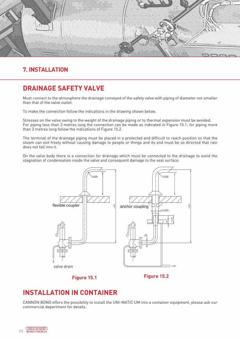
Must connect to the atmosphere the drainage conveyed of the safety valve with piping of diameter not smaller than that of the valve outlet.
To make the connection follow the indications in the drawing shown below.
Stresses on the valve owing to the weight of the drainage piping or to thermal expansion must be avoided.For piping less than 3 metres long the connection can be made as indicated in Figure 15.1; for piping more than 3 metres long follow the indications of Figure 15.2.
The terminal of the drainage piping must be placed in a protected and difficult to reach position so that the steam can exit freely without causing damage to people or things and its end must be so directed that rain does not fall into it.
On the valve body there is a connection for drainage which must be connected to the drainage to avoid the stagnation of condensation inside the valve and consequent damage to the seal surface.
INSTALLATION IN CONTAINER
CANNON BONO offers the possibility to install the UNI-MATIC UM into a container equipment, please ask our commercial department for details.
fl exible coupler anchor coupling
Figure 15.1 Figure 15.2
valve drain
25
GENERAL COMMENTS
Generator operation is completely automatic and requires nothing in particular.The operations to be performed regularly are indicated in the section below.Carrying out the programme of checks and inspections proposed here means extending the system’s lifetime and preventing possible faults and malfunctioning.
Daily operations
• Check the regulator ignition cycle.• Check the boiler supply water hardness.• Check purifier cycle. If necessary regenerate.• Check water supply pump delivery pressure.• Check whether the self-cleaner naphtha/gas filter is clean (turn upper filter handwheel).• Check smoke thermostat safety lock.• Check steam thermostat safety lock.• Discharge the generator under pressure (only for vertical generators).• Check supply pump belt tension.
Weekly operations • Clean nozzle and ignition electrodes.• Check tank fuel level.• Check naphtha pre-heater temperature.• Check operation of supply water tank float level regulator.• Check water supply pump oil level.
Monthly operations
• Clean water supply pump suction filter.• Clean burner outflows.• Clean photocell and protective glass.• Drain slime out of the water supply tank.
To protect the generator during a short shut-down period proceed as follows:Discharge the coil under pressure.Close the on-off valve water supply and the steam intake valve. Keep the relief valves of the coil and humidity separator (for vertical generators) open, wait for the generator temperature to drop to about 50°C and then close the relief valves.To protect the generator, with seasonal working with long shut-down periods, follow the precise information given in the instruction sheet enclosed.
WARNING: before performing any maintenance operation, switch the unit off by means of the switch upstream of the line, and the main switch on the control panel. Put the sign:
“ MAINTENANCE IN PROGRESS or STOPPED FOR MAINTENANCE”.
on the switches
8. MAINTENANCE
26
Three-monthly operations
• Check generator smoke side and if necessary clean with compressed air (see instructions enclosed).• Disassemble and clean naphtha/gas oil in suction filter.• Disassemble and clean naphtha pre-heater filter.• Disassemble and clean condensation discharger filter.• Disassemble and clean water supply filter.• Check safety valve.
Yearly operations
• Clean smoke side with compressed air and extracting soot.• Clean fan impeller.• Change water supply pump oil.• Check refractors.
WASHING SMOKE SIDE
Washing the smoke side of the generator is very exceptional and may be necessary to free the boiler from clogging of soot and dirt.
Generator in vertical version
• Stop the generator and discharge it.• Disassemble the burner.• Detach the chimney pipe union and hermetically close the generator connection with blank flange and
rubber gasket.• Open the lower cleaning door and extract the internal threaded plug.• Place a sheet channel under the cover for the discharge of the washing solution.• In a separate container prepare a 10% water and caustic soda solution (9 parts water and 1 part caustic
soda). Pour the solution inside the generator through the burner hole and fill up to 5 cm. from the edge of the cover inside.
• Wait 24 hours then drain completely through the lower plug; then fill and rinse the generator with clean water. Wait some time for the inside of the generator to dry then reassemble the components.
• Lubricate the thread of the internal plug with graphitised grease and screw it up tightening moderately.• Close the door, detach the blank chimney closing flange and reassemble the union section.• Assemble the burner and make the connections correctly.• Start the generator with the due precautions to eliminate the humidity absorbed by the refractors.• The operation should be performed as follows:• Light the burner and leave it lit for about 1 minute; then switch it off and wait 3-4 minutes.• Repeat the operation 3 or 4 times.
Generator in horizontal version
• Stop the generator and discharge it.• Disassemble the burner.• Detach the chimney pipe union.• Remove the generator cover.• Place a sheet channel under the cover for the discharge of the washing solution.
8. MAINTENANCE
27
• In a separate container prepare a solution of 10% water and caustic soda (9 parts water and 1 part caustic soda). Wash the inside of the generator with the solution and rinse.
• Lubricate the thread of the cover tie rods with graphitised grease.• Close the cover and reassemble the union section of the chimney.• Assemble the burner and make the connections correctly.• Start the generator with the due precautions to eliminate the humidity absorbed by the refractors.• The operation should be performed as follows:• Light the burner and leave it lit for about 1 minute; then switch it off and wait 3-4 minutes.• Repeat the operation 3 or 4 times.
Generator in vertical version
To extract the coil from the generator proceed as follows:• Remove the fuel piping and the electrical connections to the burner and disassemble the front cover.• Disassemble the water and steam connection piping and discharge.• Unscrew the ring nuts and extract the smoke sealing gaskets.• Unscrew the connecting stub pipes using a pipe wrench.
The coil thus freed can be hooked to the eye bolts and taken out of the generator.The operation can be performed by putting a suitably sized and possibly movable lifting device in position above the boiler.In the case of horizontal generators the coil can be hooked to the eye bolts and taken out of the generator on a suitably strong fork lift truck.
Assembly:• Hook the coil, lower it into the generator making sure that the connections coincide with the sleeves and
check the centring of the coil with respect to the plating inside.• Replace the front cover sealing gaskets.• Assemble the stub pipes packing the conical threads with a little teflon tape and tighten completely.• Put new smoke sealing gaskets in the housings leaving them protruding by the sleeves about 5–10 mm.
for later adjustments.• Lubricate the threading with graphitised grease and tighten the ring nuts.• Lubricate the stud bolts and reassemble the upper cover.• Connect the water, steam and discharge piping and make the connections to the burner again.• Start the generator and check the seals, adjust if necessary.
INSTRUCTIONS FOR CHEMICAL DESCALING
1. With coil empty: wash the inside with just water by means of the supply pump. (If this operation is made possible by the general state of the coil, it should last for a few minutes).
2. Immediately afterwards stop the pump and drain.3. Remove the meshes of the filters before the condensation discharge (in the version with steam separator)
and the water suction pump.4. Prepare the descaling acid solution in a suitable container (water + commercial hydrochloric acid (HCI
33%) + inhibitor “Lithsolvent”),according to the table specified.5. Descale the coil putting the acid solution in from the top (steam intake pipe) and recovering it in the col-
lection container draining the solution itself from the supply connection. The operation of putting in and recovering the descaling solution should be performed with a small pump
which allows the continuous circulation from coil to the tank in closed cycle. The pump delivery is proportional to the boiler capacity: E.g.: for a UM 30- about 300 It/h; for UM50- about 500 lt/h etc. For the unions the PVC hoses available on the market can be used.

28
The acid solution specified in the table is sufficient to remove a thickness of about 2 mm. of scale along the whole coil.
6) The closed-cycle operation should last for at least 2-3 hours and in any case until the formation of foam is seen in the container.
N.B. If there is considerable scaling, the operation should be repeated completely, renewing the solution once the time mentioned above has elapsed
7) When the operation is finished empty the coil and the container completely. Collect the solution and neutralise it before draining. Wash the coil and the container with clean water under pressure, then drain again.8) In the normal container prepare a neutralised alkaline solution with water and sodium bicarbonate (Solvay
Soda) base in the proportion specified in the table.9) Circulate the solution in the coil for about 30’ then drain. This operation would be better performed hot (60–70 °C), lighting the burner from time to time.10) Cool, drain and wash carefully to remove the operation residues from: valves, dischargers, etc. Reas-
semble the previously removed filter meshes, replace the piping and start the boiler.
UNI-MATIC
UM model
Tank capac.
(minimum).
L
Water
content
L
Acid
content
L
Cont. Inhib.
“Lithsolvent”
L
Content
“ solvay
soda”
kg
UM 30 100 80 11 0.50 3
UM 50 150 120 16 0.75 4
UM 100 200 160 22 1 6
UM150,
UM 200300 200 30 1.5 10
UM 300 500 300 40 2 15
Important: in order to operate in security we recommend to ask to our assistance contacting Bono Energia
S.p.a. (+39 02 55302848).
DOWNTIME
When the generator is placed out of operation for a short time there are no particular precautions; in the case of long downtime the generator should be set up to avoid deterioration to the coil and the equipment.
• Clean the smoke side of the generator carefully by washing with water and caustic soda.• Immediately afterwards start the generator again for a short time to remove the humidity completely.• Discharge the coil under pressure and then leave the generator to cool.• In a separate container prepare an alkaline water solution with 50% sodium bicarbonate “Solvay Soda”
(see tab. 7)• Fill the coil completely and fill the water supply circuit up to the on-off valve on the pump suction, with the
alkaline solution described above.• Close all the generator valves.• Put a blank on-off flange between the generator and the chimney.• Lubricate the valve closing screws and all the generator bolts and stud bolts.• Protect the control panel and all the equipment against dust and external humidity.
N.B. To protect the coil avoid the dangers of frost.
8. MAINTENANCE
Table 7 Chemical descaling standard data
29
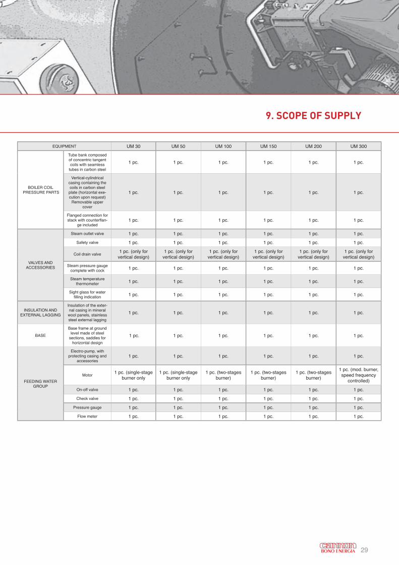
9. SCOPE OF SUPPLY
EQUIPMENT UM 30 UM 50 UM 100 UM 150 UM 200 UM 300
BOILER COIL PRESSURE PARTS
Tube bank composed of concentric tangent coils with seamless
tubes in carbon steel
1 pc. 1 pc. 1 pc. 1 pc. 1 pc. 1 pc.
Vertical-cylindrical casing containing the coils in carbon steel plate (horizontal exe-cution upon request)
Removable upper cover
1 pc. 1 pc. 1 pc. 1 pc. 1 pc. 1 pc.
Flanged connection for stack with counterfl an-
ge included1 pc. 1 pc. 1 pc. 1 pc. 1 pc. 1 pc.
VALVES AND ACCESSORIES
Steam outlet valve 1 pc. 1 pc. 1 pc. 1 pc. 1 pc. 1 pc.
Safety valve 1 pc. 1 pc. 1 pc. 1 pc. 1 pc. 1 pc.
Coil drain valve1 pc. (only for
vertical design)1 pc. (only for
vertical design)1 pc. (only for
vertical design)1 pc. (only for
vertical design)1 pc. (only for
vertical design)1 pc. (only for
vertical design)
Steam pressure gauge complete with cock 1 pc. 1 pc. 1 pc. 1 pc. 1 pc. 1 pc.
Steam temperature thermometer 1 pc. 1 pc. 1 pc. 1 pc. 1 pc. 1 pc.
Sight glass for water fi lling indication 1 pc. 1 pc. 1 pc. 1 pc. 1 pc. 1 pc.
INSULATION AND EXTERNAL LAGGING
Insulation of the exter-nal casing in mineral
wool panels, stainless steel external lagging
1 pc. 1 pc. 1 pc. 1 pc. 1 pc. 1 pc.
BASE
Base frame at ground level made of steel
sections, saddles for horizontal design
1 pc. 1 pc. 1 pc. 1 pc. 1 pc. 1 pc.
FEEDING WATER GROUP
Electro-pump, with protecting casing and
accessories1 pc. 1 pc. 1 pc. 1 pc. 1 pc. 1 pc.
Motor1 pc. (single-stage
burner only1 pc. (single-stage
burner only1 pc. (two-stages
burner)1 pc. (two-stages
burner)1 pc. (two-stages
burner)
1 pc. (mod. burner, speed frequency
controlled)
On-off valve 1 pc. 1 pc. 1 pc. 1 pc. 1 pc. 1 pc.
Check valve 1 pc. 1 pc. 1 pc. 1 pc. 1 pc. 1 pc.
Pressure gauge 1 pc. 1 pc. 1 pc. 1 pc. 1 pc. 1 pc.
Flow meter 1 pc. 1 pc. 1 pc. 1 pc. 1 pc. 1 pc.
30
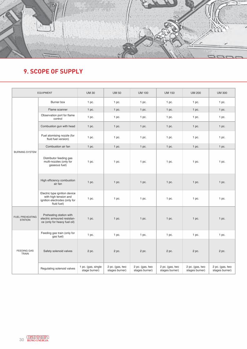
9. SCOPE OF SUPPLY
EQUIPMENT UM 30 UM 50 UM 100 UM 150 UM 200 UM 300
BURNING SYSTEM
Burner box 1 pc. 1 pc. 1 pc. 1 pc. 1 pc. 1 pc.
Flame scanner 1 pc. 1 pc. 1 pc. 1 pc. 1 pc. 1 pc.
Observation port for fl ame control
1 pc. 1 pc. 1 pc. 1 pc. 1 pc. 1 pc.
Combustion gun with head 1 pc. 1 pc. 1 pc. 1 pc. 1 pc. 1 pc.
Fuel atomising nozzle (for fl uid fuel version)
1 pc. 1 pc. 1 pc. 1 pc. 1 pc. 1 pc.
Combustion air fan 1 pc. 1 pc. 1 pc. 1 pc. 1 pc. 1 pc.
Distributor feeding gas multi-nozzles (only for
gaseous fuel)1 pc. 1 pc. 1 pc. 1 pc. 1 pc. 1 pc.
High effi ciency combustion air fan
1 pc. 1 pc. 1 pc. 1 pc. 1 pc. 1 pc.
Electric type ignition device with high tension and
ignition electrodes (only for fl uid fuel)
1 pc. 1 pc. 1 pc. 1 pc. 1 pc. 1 pc.
FUEL PREHEATING STATION
Preheating station with electric armoured resistan-ce (only for heavy fuel oil)
1 pc. 1 pc. 1 pc. 1 pc. 1 pc. 1 pc.
FEEDING GAS TRAIN
Feeding gas train (only for gas fuel)
1 pc. 1 pc. 1 pc. 1 pc. 1 pc. 1 pc.
Safety solenoid valves 2 pc. 2 pc. 2 pc. 2 pc. 2 pc. 2 pc.
Regulating solenoid valves1 pc. (gas, single
stage burner)2 pc. (gas, two stages burner)
2 pc. (gas, two stages burner)
2 pc. (gas, two stages burner)
2 pc. (gas, two stages burner)
2 pc. (gas, two stages burner)

31
9. SCOPE OF SUPPLY
EQUIPMENT UM 30 UM 50 UM 100 UM 150 UM 200 UM 300
BURNING CONTROL AND
SAFETY EQUIPMENT
Cycle programming panel for burner ignition and fl ame control (safety automatic
device)1 pc. 1 pc. 1 pc. 1 pc. 1 pc. 1 pc.
Temperature switches for fuel temperature regulation (only heavy fuel oil)
1 pc. 1 pc. 1 pc. 1 pc. 1 pc. 1 pc.
Gas valves seal control device / / / 1 pc. 1 pc. 1 pc.
Max/min gas pressure switch (only gas fuel)
1 pc. 1 pc. 1 pc. 1 pc. 1 pc. 1 pc.
Shut-down pressure switch for very high steam pressure
1 pc. 1 pc. 1 pc. 1 pc. 1 pc. 1 pc.
Shut-down temperature switch for high steam temperature
1 pc. 1 pc. 1 pc. 1 pc. 1 pc. 1 pc.
Shut-down temperature switch for high fl ues temperature
1 pc. 1 pc. 1 pc. 1 pc. 1 pc. 1 pc.
Control fl ow switch for feed water circu-lation
1 pc. 1 pc. 1 pc. 1 pc. 1 pc. 1 pc.
ELECTRIC WIRINGWith fl exible conduits and tight terminal
fi ttings for high mechanical resistance and water proof sealing
1 pc. 1 pc. 1 pc. 1 pc. 1 pc. 1 pc.
ELECTRIC PANEL
Steel cabinet, oven painting, front door, IP54 protection
1 pc. 1 pc. 1 pc. 1 pc. 1 pc. 1 pc.
Power section, main switch and door locking device, magneto-thermal switches to protect each user, tropicalized power
contactors
1 pc. 1 pc. 1 pc. 1 pc. 1 pc. 1 pc.
Control auxiliary section, ignition and fl ame control panel, alarms and shut-down logic, alarm horn contacts, auxiliaries protection
fuses
1 pc. 1 pc. 1 pc. 1 pc. 1 pc. 1 pc.
Operators panel, burner START/STOP switch/indicator, feed pump START/STOP switch/indicator, alarms acknowledgement
with lamps
1 pc. 1 pc. 1 pc. 1 pc. 1 pc. 1 pc.
Feed water group frequency changer / /1 pc.
(modulating regulation)
1 pc. (modulating regulation)
1 pc. (modulating regulation)
1 pc. (modulating regulation
32
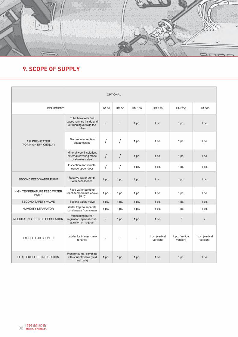
9. SCOPE OF SUPPLY
OPTIONAL
EQUIPMENT UM 30 UM 50 UM 100 UM 150 UM 200 UM 300
AIR PRE-HEATER (FOR HIGH EFFICIENCY)
Tube bank with fl ue gases running inside and
air running outside the tubes
/ / 1 pc. 1 pc. 1 pc. 1 pc.
Rectangular section shape casing / / 1 pc. 1 pc. 1 pc. 1 pc.
Mineral wool insulation, external covering made
of stainless steel/ / 1 pc. 1 pc. 1 pc. 1 pc.
Inspection and mainte-nance upper door / / 1 pc. 1 pc. 1 pc. 1 pc.
SECOND FEED WATER PUMPReserve water pump,
with accessories1 pc. 1 pc. 1 pc. 1 pc. 1 pc. 1 pc.
HIGH TEMPERATURE FEED WATER PUMP
Feed water pump to reach temperature above
95 °C 1 pc. 1 pc. 1 pc. 1 pc. 1 pc. 1 pc.
SECOND SAFETY VALVE Second safety valve 1 pc. 1 pc. 1 pc. 1 pc. 1 pc. 1 pc.
HUMIDITY SEPARATORWater trap, to separate condensate from steam
1 pc. 1 pc. 1 pc. 1 pc. 1 pc. 1 pc.
MODULATING BURNER REGULATIONModulating burner
regulation, special confi -guration on request
/ 1 pc. 1 pc. 1 pc. / /
LADDER FOR BURNERLadder for burner main-
tenance/ / /
1 pc. (vertical version)
1 pc. (vertical version)
1 pc. (vertical version)
FLUID FUEL FEEDING STATIONPlunger pump, complete with shut-off valve (fl uid
fuel only)1 pc. 1 pc. 1 pc. 1 pc. 1 pc. 1 pc.
33
10. APPENDIX 1. FUEL CONSUMPTION CALCULATION
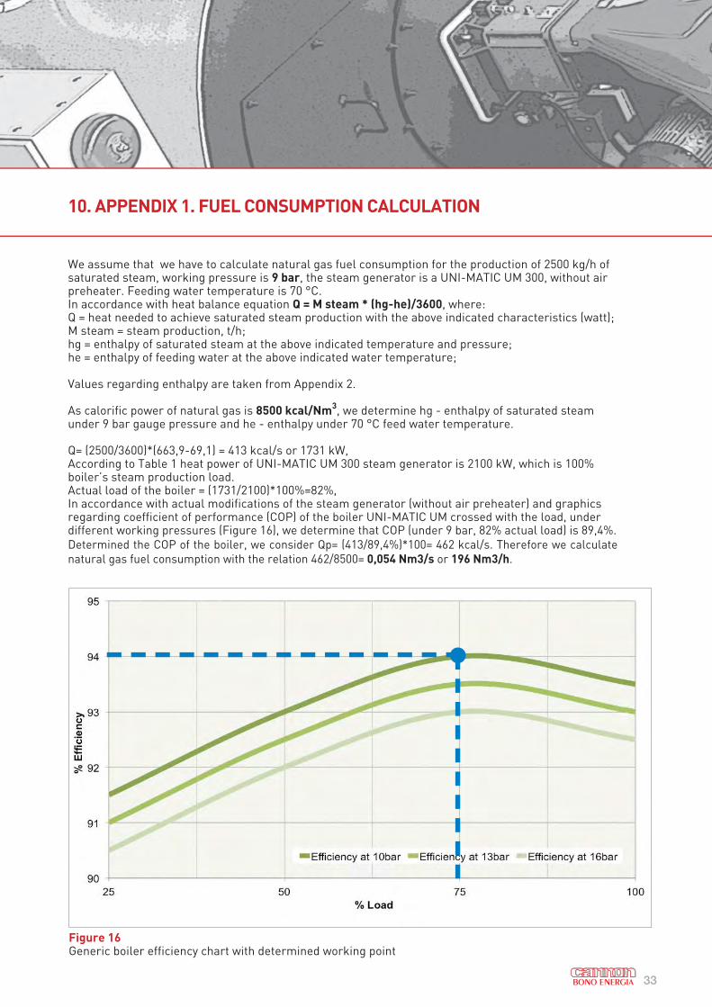
Figure 16Generic boiler efficiency chart with determined working point
We assume that we have to calculate natural gas fuel consumption for the production of 2500 kg/h of saturated steam, working pressure is 9 bar, the steam generator is a UNI-MATIC UM 300, without air preheater. Feeding water temperature is 70 °C.In accordance with heat balance equation Q = M steam * (hg-he)/3600, where:Q = heat needed to achieve saturated steam production with the above indicated characteristics (watt);M steam = steam production, t/h;hg = enthalpy of saturated steam at the above indicated temperature and pressure;he = enthalpy of feeding water at the above indicated water temperature;
Values regarding enthalpy are taken from Appendix 2.
As calorific power of natural gas is 8500 kcal/Nm3, we determine hg - enthalpy of saturated steam
under 9 bar gauge pressure and he - enthalpy under 70 °C feed water temperature.
Q= (2500/3600)*(663,9-69,1) = 413 kcal/s or 1731 kW,According to Table 1 heat power of UNI-MATIC UM 300 steam generator is 2100 kW, which is 100% boiler’s steam production load.Actual load of the boiler = (1731/2100)*100%=82%,In accordance with actual modifications of the steam generator (without air preheater) and graphics regarding coefficient of performance (COP) of the boiler UNI-MATIC UM crossed with the load, under different working pressures (Figure 16), we determine that COP (under 9 bar, 82% actual load) is 89,4%.
Determined the COP of the boiler, we consider Qp= (413/89,4%)*100= 462 kcal/s. Therefore we calculate
natural gas fuel consumption with the relation 462/8500= 0,054 Nm3/s or 196 Nm3/h.

34
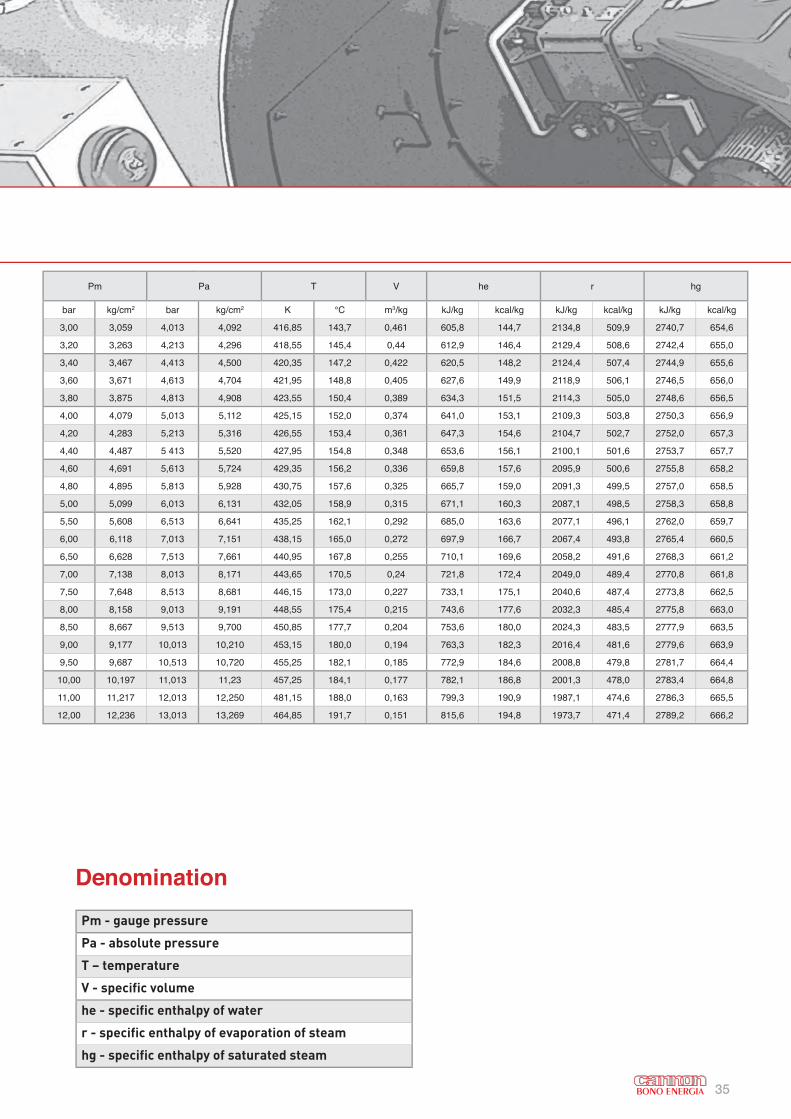
11. APPENDIX 2. THERMODYNAMIC CHARACTERISTICS OF SATURATED STEAM
Pm Pa T V he r hg
bar kg/cm2 bar kg/cm2 K °C m3/kg kJ/kg kcal/kg kJ/kg kcal/kg kJ/kg kcal/kg
0,050 0,051 306,05 32,9 28,191 137,7 32,9 2425 679,2 2562,7 612,1
0,100 0,102 318,95 45,8 14,674 191,8 45,8 2394,4 571,9 2586,2 617,7
0,150 0,153 327,15 54,0 10,023 225,9 54,0 2374,8 567,2 2600,7 621,2
0,200 0,204 333,15 60,0 7,65 251,5 60,1 2359,7 563,6 2611,2 623,7
0,250 0,255 338,15 65,0 6,204 272 65,0 2347,5 560,7 2619,5 625,7
0,300 0,306 342,25 69,1 5,229 289,3 69,1 2337,5 558,3 2626,8 627,4
0,350 0,357 345,85 72,7 4,526 304,3 72,7 2328,7 556,2 2633 628,9
0,400 0,408 349,05 75,9 3,994 317,6 75,9 2320,7 554,3 2638,3 630,2
0,450 0,459 351,85 78,7 3,577 329,6 78,8 2313,6 552,6 2643,2 631,4
0,500 0,51 354,45 81,3 3,240 340,5 81,4 2306,9 551,0 2647,4 632,4
0,6 0,612 359,05 85,9 2,732 359,9 86,0 2295,2 548,2 2655,1 634,2
0,7 0,714 363,05 89,9 2,365 376,7 90,0 2284,3 545,6 2661,0 635,6
0,8 0,816 366,65 93,5 2,087 391,7 93,6 2275,5 543,5 2667,2 637,1
0,9 0,918 369,85 96,7 1,869 405,2 96,8 2267,2 541,5 2672,4 638,3
1,0 1,020 372,75 99,6 1,694 417,5 99,8 2259,2 539,6 2676,7 639,4
0 0 1,013 1,033 373,15 100,0 1,673 419,1 100,1 2258,4 539,4 2677,5 639,5
0,05 0,051 1,063 1,084 374,55 101,4 1,601 425,0 101,5 2254,2 538,4 2679,1 639,9
0,10 0,102 1,113 1,135 375,75 102,6 1,533 430,4 102,8 2251,2 537,7 2681,6 640,5
0,15 0,153 1,163 1,186 378,25 105,1 1,471 435,8 104,1 2247,9 536,9 2683,7 641,0
0,20 0,204 1,213 1,237 379,35 106,2 1,414 440,9 105,3 2245,0 536,2 2685,8 641,5
0,30 0,306 1,313 1,339 380,55 107,4 1,312 450,5 107,6 2238,7 534,7 2689,2 642,3
0,40 0,408 1,413 1,441 382,65 109,5 1,225 459,7 109,8 2232,8 533,3 2692,5 643,1
0,50 0,510 1,513 1,543 384,75 111,6 1,149 468,5 111,9 2227,0 531,9 2695,5 643,8
0,60 0,612 1,613 1,645 386,65 113,5 1,038 476,5 113,8 2221,5 530,6 2698,0 644,4
0,70 0,714 1,713 1,747 388,55 115,4 1,024 484,4 115,7 2216,9 529,5 2701,3 645,2
0,80 0,816 1,813 1,849 390,25 117,1 0,971 491,9 117,5 2211,9 528,3 2703,8 645,8
0,90 0,918 1,913 1,951 391,95 118,8 0,923 499,1 119,2 2206,9 527,1 2705,9 646,3
1,00 1,020 2,013 2,053 393,55 120,4 0,881 505,8 120,8 2202,3 526,0 2708,0 646,8
1,10 1,122 2,113 2,155 395,05 121,9 0,841 512,5 122,4 2198,5 525,1 2711,0 647,5
1,20 1,224 2,213 2,257 396,55 123,4 0,806 519,2 124,0 2194,3 524,1 2713,5 648,1
1,30 1,326 2,313 2,359 398,05 124,9 0,773 525,0 125,4 2190,1 523,1 2715,1 648,5
1,40 1,428 2,413 2,461 399,45 126,3 0,743 530,9 126,8 2186,3 522,2 2717,2 649,0
1,50 1,530 2,513 2,563 400,75 127,6 0,714 536,3 128,1 2181,7 521,1 2718,1 649,2
1,60 1,632 2,613 2,664 402,05 128,9 0,689 542,2 129,5 2178,8 520,4 2721 649,9
1,70 1,733 2,713 2,766 403,25 130,1 0,665 547,2 130,7 2175 519,5 2722,3 650,2
1,80 1,835 2,813 2,868 404,55 131,4 0,643 552,7 132,0 2171,3 518,6 2723,9 650,6
1,90 1,937 2,913 2,970 405,65 132,5 0,622 557,7 133,2 2167,9 517,8 2725,6 651,0
2,00 2,039 3,013 3,072 406,85 133,7 0,603 562,7 134,4 2164,6 517 2727,3 851,4
2,20 2,243 3,213 3,278 409,05 135,9 0,568 571,9 136,6 2158,3 515,5 2730,2 652,1
2,40 2,447 3,413 3,480 411,15 138,0 0,536 581,1 138,8 2152 514,0 2733,1 652,8
2,60 2,651 3,613 3,684 413,15 140,0 0,509 589,5 140,8 2146,2 512,6 2735,7 653,4
2,80 2,855 3,813 3,888 415,05 141,9 0,483 597,9 142,8 2140,3 511,2 2738,2 654,0
35
Pm Pa T V he r hg
bar kg/cm2 bar kg/cm2 K °C m3/kg kJ/kg kcal/kg kJ/kg kcal/kg kJ/kg kcal/kg
3,00 3,059 4,013 4,092 416,85 143,7 0,461 605,8 144,7 2134,8 509,9 2740,7 654,6
3,20 3,263 4,213 4,296 418,55 145,4 0,44 612,9 146,4 2129,4 508,6 2742,4 655,0
3,40 3,467 4,413 4,500 420,35 147,2 0,422 620,5 148,2 2124,4 507,4 2744,9 655,6
3,60 3,671 4,613 4,704 421,95 148,8 0,405 627,6 149,9 2118,9 506,1 2746,5 656,0
3,80 3,875 4,813 4,908 423,55 150,4 0,389 634,3 151,5 2114,3 505,0 2748,6 656,5
4,00 4,079 5,013 5,112 425,15 152,0 0,374 641,0 153,1 2109,3 503,8 2750,3 656,9
4,20 4,283 5,213 5,316 426,55 153,4 0,361 647,3 154,6 2104,7 502,7 2752,0 657,3
4,40 4,487 5 413 5,520 427,95 154,8 0,348 653,6 156,1 2100,1 501,6 2753,7 657,7
4,60 4,691 5,613 5,724 429,35 156,2 0,336 659,8 157,6 2095,9 500,6 2755,8 658,2
4,80 4,895 5,813 5,928 430,75 157,6 0,325 665,7 159,0 2091,3 499,5 2757,0 658,5
5,00 5,099 6,013 6,131 432,05 158,9 0,315 671,1 160,3 2087,1 498,5 2758,3 658,8
5,50 5,608 6,513 6,641 435,25 162,1 0,292 685,0 163,6 2077,1 496,1 2762,0 659,7
6,00 6,118 7,013 7,151 438,15 165,0 0,272 697,9 166,7 2067,4 493,8 2765,4 660,5
6,50 6,628 7,513 7,661 440,95 167,8 0,255 710,1 169,6 2058,2 491,6 2768,3 661,2
7,00 7,138 8,013 8,171 443,65 170,5 0,24 721,8 172,4 2049,0 489,4 2770,8 661,8
7,50 7,648 8,513 8,681 446,15 173,0 0,227 733,1 175,1 2040,6 487,4 2773,8 662,5
8,00 8,158 9,013 9,191 448,55 175,4 0,215 743,6 177,6 2032,3 485,4 2775,8 663,0
8,50 8,667 9,513 9,700 450,85 177,7 0,204 753,6 180,0 2024,3 483,5 2777,9 663,5
9,00 9,177 10,013 10,210 453,15 180,0 0,194 763,3 182,3 2016,4 481,6 2779,6 663,9
9,50 9,687 10,513 10,720 455,25 182,1 0,185 772,9 184,6 2008,8 479,8 2781,7 664,4
10,00 10,197 11,013 11,23 457,25 184,1 0,177 782,1 186,8 2001,3 478,0 2783,4 664,8
11,00 11,217 12,013 12,250 481,15 188,0 0,163 799,3 190,9 1987,1 474,6 2786,3 665,5
12,00 12,236 13,013 13,269 464,85 191,7 0,151 815,6 194,8 1973,7 471,4 2789,2 666,2
Pm - gauge pressure
Pa - absolute pressure
T – temperature
V - specific volume
he - specific enthalpy of water
r - specific enthalpy of evaporation of steam
hg - specific enthalpy of saturated steam
Denomination
Bono Energia S.p.A
Via Resistenza 12 - 20068 Peschiera Borromeo (Mi) - Italy
Phone +39 0255302848 - Fax +39 025471955
www.bono.it
Ed. N°1
DISCLAIMER: All the data presented in this technical book are indicative and subject of changing due to
product customization and innovation processes.
They must be considered by the user only at the first stage of product selection; CANNON BONO declines
any responsibility for wrong usage of mentioned data and invites the user to contact our commercial
department for further details.