technical and cost assessment of the pcast machine final
TRANSCRIPT

Technical and Cost Assessment of the PCAST Machine
Final Report
PCAST ITER
Volume I
Chapter 2.0 Trade Studies
prepared by PCAST Study Group
December, 1995
9 l-95 1208-MWDBMontgomery-0 1
2.0 Trade Studies (W. Reiersen, PPPL and J. Galambos, ORNL)
2.1 Comparison of the ITER and PCAST devices
The PCAST study was initiated to determine if a reduced ITER mission could be accomplished in a device which costs substantially less. The reduced mission would retain most of the burning-plasma physics and burn-control aspects of the ITER mission (up to particle-confinement time scales), but eliminate the nuclear testing and engineering prototype aspects. Descoping the mission in this way allows a number of cost-saving design changes to be considered:
l Adopt copper coils l Adopt stronger plasma shaping l Reduce the number of pulses l Reduce the neutron wall load and fluence l Reduce the pulse length
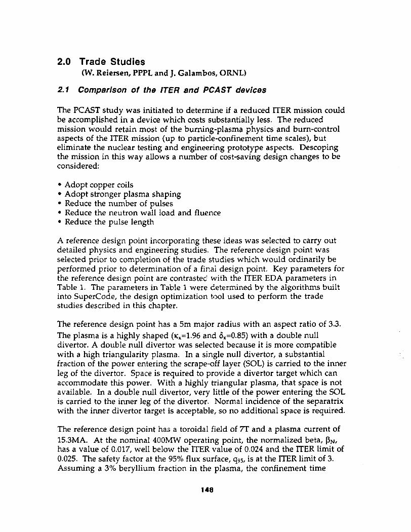
A reference design point incorporating these ideas was selected to carry out detailed physics and engineering studies. The reference design point was selected prior to completion of the trade studies which would ordinarily be performed prior to determination of a fir.ai design point. Key parameters for the reference design point are contrasted with the ITER EDA parameters in Table 1. The parameters in Table 1 were determined by the algorithms built into SuperCode, the design optimization tool used to perform the trade studies described in this chapter.
The reference design point has a 5m major radius with an aspect ratio of 3.3. The plasma is a highly shaped (~,=1.96 and c&=0.85) with a double null divertor. A double null divertor was selected because it is more compatible with a high triangularity plasma. In a single null divertor, a substantial fraction of the power entering the scrape-off layer (SOL) is carried to the inner leg of the divertor. Space is required to provide a divertor target which can accommodate this power. With a highly triangular plasma, that space is not available. In a double null divertor, very little of the power entering the SOL is carried to the inner leg of the divertor. Normal incidence of the separatrix with the inner divertor target is acceptable, so no additional space is required.
The reference design point has a toroidal field of 7T and a plasma current of 15.3MA. At the nominal 400MW operating point, the normalized beta, PN, has a value of 0.017, well below the ITER value of 0.024 and the ITER limit of 0.025. The safety factor at the 95% flux surface, 495, is at the ITER limit of 3. Assuming a 3% beryllium fraction in the plasma, the confinement time
148

required for ignition is 0.74 times the confinement time predicted by using ITER ELM-free H-mode scaling. For this report, the ratio of the confinement time required for ignition to the confinement time predicted by using lTER ELM-free H-mode scaling will be referred to as H. For ITER, operating at 15OOMw with the same beryllium fraction, the required H was calculated by SuperCode to be 0.81. The difference between the H values required for the ITER and PCAST reference designs is traceable to the algorithm used in SuperCode to calculate the plasma volume and to the elongation used to calculate the energy confinement time (K, here, ~95 elsewhere). Calculations presented elsewhere in this report show the ignition margin of the two designs to be the same. Because of its nuclear testing mission, lTER requires a neutron wall load of -lMW/m* and 5x10’ pulses. PCAST is not designed for a nuclear testing mission so its neutron wall load is only 0.7MW/m2 with a design life of 5~10~ full field pulses.
Table 1 - Key Parameters for the ITER EDA and PCAST Machines
149

The reference PCAST design utilizes high conductivity copper coils which are not actively cooled during a pulse. The TF coils are of wound construction in a stainless steel case. The electrical energy dissipated during a pulse causes the temperature in the PF and TF coils to rise. The coils are cooled down to temperatures of 30K for PFl and 80K for all other coils between pulses. PFl is cooled to the lower temperature in order to allow a burn time of 120s. In the reference PCAST design, the peak TF coil temperature is calculated to be 242K. The peak PF coil temperature occurs in PFl (the solenoid coil closest to the midplane) and is calculated to be 238K, neglecting magnetoresistive effects.
At the low temperature (30K) and high field (-30T) environment of PFl, magnetoresistive effects can be important, eroding the apparent benefit of operating at these low temperatures. Also, it is more expensive to remove a joule of energy at 30K than at 80K which further erodes this benefit. For these reasons, the trade studies which were subsequently performed assumed an initial temperature of 80K for all coils with the associated penalty in machine size. A maximum temperature of 300K was also imposed.
The centering force on the TF coils is reacted by bucking off the central solenoid as in ITER. Structural allowables adopted for the PCAST study were as follows:
l General primary membrane stresses should be less than 2/3 yield at operating temperature l Primary membrane plus bending stresses should be less than yield at operating temperature l Total primary plus secondary stress should be less tf.an twice yield
Detailed structural analyses described later in this report confirm that these allowables can be met in the reference PCAST design. However, bending stresses, thermal stresses, and fatigue/fracture phenomena cannot be readily calculated in a systems code model. In performing trade studies, simple models to predict primary membrane stresses were developed and applied with the constraint that the primary membrane stress should be less than 2/3 yield
The ITER EDA design features 1OOMW of auxiliary heating and non- inductive current drive whereas the reference PCAST design features 60MW. For ignition devices in which auxiliary heating and non-inductive current drive are not required during burn, the algorithms in SuperCode do not provide an accurate assessment of device requirements. Therfore, for trade studies of superconducting options, the auxiliary heating/current drive complement was fixed at 100MW. By contrast, for trade studies of adiabatic copper options, the auxiliary heating/current drive complements was fixed at 60MW. Appropriate allowances must be applied when interpreting estimated
150
costs for devices which differ significantly from the ITER EDA and reference PCAST designs.
In addition to calculating physics and engineering parameters of candidate devices, SuperCode has cost algorithms which are used for design optimization with cost as the objective function. The engineering and physics assumptions and constraints used in this study are described in Appendicies A-l - A-3. The cost algorithms in SuperCode are described in Appendix A-4. Generally the physics modeling is similar to that used in ITER trade studies. The cost of the reference PCAST design according to these scalings would be less than half the cost (49%) of the ITER EDA design. For comparison, the cost of the reference PCAST design per the detailed cost estimate (described later in the report) would be 45% of the reference ITER EDA cost.
Design Point Description
ITER EDA Optimized (minimum cost) ITER Adopt stronger shaping - increase q from 1.74 to 1.96 - increase S, from 0.34 to 0.85 Eliminate nuclear testing - relax lMW/m2 NWL constraint - reduce number of pulses from Se4 to 5e3 Reduce bum time from -1tWOs to -130s Reference PCAST Design
Superconducting Coil Adiabatic Copper Variants Coil Variants
Major Relative Major Relative Radius cost Radius cost
(ml (ml 8.15 1 i, i, j : “,
8.59 0.94 8.20 0.89 7.46 0.83 7.80 0.85
7.34 1’.71 6.91 0.67
7.14 0.73 4.81 0.44 :.:,.. ..: : ..,..:.., 5.00 0.49
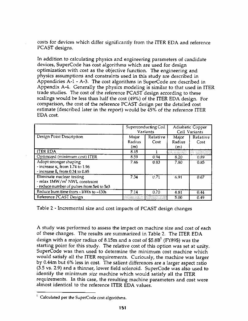
Table 2 - Incremental size and cost impacts of PCAST design changes
A study was performed to assess the impact on machine size and cost of each of these changes. The results are summarized in Table 2. The ITER EDA design with a major radius of 8.15m and a cost of $S.BB’ (FY89$) was the starting point for this study. The relative cost of this option was set at unity. SuperCode was then used to determine the minimum cost machine which would satisfy all the ITER requirements. Curiously, the machine was larger by 0.44m but 6% less in cost. The salient differences are a larger aspect ratio (3.5 vs. 2.9) and a thinner, lower field solenoid. SuperCode was also used to identify the minimum size machine which would satisfy all the ITER requirements. In this case, the resulting machine parameters and cost were almost identical to the reference ITER EDA values.
’ Calculated per the SuperCode cost algorithms.
151

The next step was to adopt stronger shaping. To reflect this, the surface elongation, K~, was increased from 1.74 to 1.96 while the surface triangularity, S,, was increased from 0.34 to 0.85. The single null divertor configuration was kept with no penalty in the radial build although it would be necessary to go to a double null configuration for this high triangularity plasma. Stronger shaping appears to be a significant benefit, reducing the relative cost by 11% (from 94% to 83%) from the “optimized” ITER design. The major radius is reduced by 1.13m. The benefits of adopting strong shaping are less than what they would be in the absence of the neutron wall load constraint of lMW/m*. Unconstrained, increasing the elongation tends to lower the neutron wall load. Thus, if we changed the order of adopting stronger shaping and eliminating nuclear testing, a greater impact would be ascribed to stronger shaping.
One caveat that goes with the stronger shaping is that the solenoid can no longer be monolithic but rather must be segmented. This significantly complicates the design of the central solenoid assembly. Strong shaping also significantly adds to the out-of-plane loads on the TF inner leg. Also, no cost penalty associated with increased difficulty of vertical control was taken.
Eliminating the nuclear testing aspects of the mission allows the neutron wall load constraint to be removed. It also reduces the number of pulses required by an order of magnitude (but this latter effect has no impact within the confines of the systems code models). Changing these factors allows the major radius to be decreased by another 0.12m with an attendant cost reduction, from 83% to 71%. The machine went to a significantly higher aspect ratio (4.1 vs. 3.6) with a lower plasma current (12MA vs. 167MA). It also went from being constrained by the beta limit (to satisfy the NWL constraint) to being constrained by confinement (H=0.81). The neutron wall load was reduced by 50%. Although the fluence would be substantially lower in this machine, the shield thickness was kept the same to guard against increased nuclear heating in the TF coil.
The final step taken was to reduce the burn time from -1000s to -120s. With the shorter burn time, the major radius could be reduced by 0.2m with a very modest reduction of 1% in relative cost. Here again, although the fluence would be reduced with the shorter burn time, the shield thickness was kept the same to guard against increased nuclear heating in the TF coil. The modest impact of reducing the burn time is consistent with expectations for a superconducting tokamak.
In summary, if all of the changes embodied in the PCAST reference design were implemented in a superconducting tokamak, the major radius could be reduced by lm relative to the lTER EDA design with a reduction in cost of
152

30%. These reductions are mainly derived by adopting stronger shaping and eliminating the neutron wall load constraint.
In an adiabatic copper design such as the reference PCAST design, more dramatic improvements can be derived. An adiabatic copper coil design which satisfied all of the ITER requirements would be almost as large and costly as the IT’ER EDA design with a major radius of 8.2m and a relative cost of 89% and lack HER’s arbitrary pulse length capability for steady-state scenario development. It might be expected that an actively cooled copper coil design would be preferred to an adiabatic copper coil design for long pulse lengths. However, time did not permit making the necessary code modifications to perform the trade studies required to quantify the size and cost of this option.
Modest reductions in major radius (-0.4m) and relative cost (-4%) can be derived by adopting stronger shaping. For the adiabatic copper coil design, adopting stronger shaping drives the aspect ratio up from 3.6 to 4.3. As with the superconducting option, the benefits of stronger shaping are masked by the lMW/m* neutron wall load requirement. If we changed the order of adopting stronger shaping and eliminating nuclear testing, a greater impact would be ascribed to stronger shaping.
Eliminating the nuclear testing requirement (which allows the neutron wall load constraint to be removed and the number of pulses reduced) has a pronounced effect. The major radius can be decreased by an additional 0.89m with an attendant relative cost decrease cf 18%. Part of the decrease is attributable to the shield thickness being reduced by 0.2m due to the reduced fluence.
The most pronounced effect on major radius and cost, however, is derived by allowing the burn time to be decreased from -1000s to -120s. Here too, the shield thickness was reduced by 0.2m due to the lower fluence for the shorter pulse length. The result of reducing the burn time is a decrease in major radius of 2.lm and decrease in relative cost of 23%. Note that the major radius of this machine is 4.81m which is less than the 5m major radius of the reference PCAST design despite the 80K cooling constraint. The smaller major radius is primarily due to the higher H factor used (0.81 a la ITER vs. 0.74 for PCAST). This difference between the H values required for the ITER and PCAST reference designs is traceable to the algorithm used in SuperCode to calculate the plasma volume and to the elongation used to calculate the energy confinement time.
In summary, if alI of the changes embodied in the PCAST reference design were implemented in an “optimized” adiabatic copper coil tokamak, the major radius could be reduced by 3.3m relative to the ITER EDA design with a reduction in cost of 56%. These reductions are larger than for a
153

superconducting tokamak because adiabatic copper coils are sensitive to burn time (unlike superconducting coils) and the shield thickness between the TF and plasma was assumed to be driven by integrated values (radiation damage and activation), rather than instantaneous values (nuclear heating).
2.2 Sensitivity studies around the “optimized” PCAST design point
In the preceding section, an “optimized” PCAST design point with a major radius of 4.81m and a relative cost of 44% was identified. Trade studies were subsequently performed around that design point to examine the sensitivities of size and cost to key parameters such as elongation, aspect ratio, confinement enhancement (H), allowable stress, and burn time. The results of these studies provide insight into possible directions for future studies.
Aspect ratio
Design points were developed using the same ground rules as for the “optimized” PCAST design point except that the aspect ratio was varied over the range of 2.5 to 5. The results of the aspect ratio scan are illustrated in Figure 1. The minimum size and cost occur in the neighborhood of A=3.4. As aspect ratio is increased, neutron wall load and normalized beta increase. The cost is only weakly sensitive to aspect ratio between A=3 and A=4.5. At aspect ratios above 4.5, the cost sensitivity is increased because the design is constrained to a maximum PN of 2.5% and a neutron wall load of lMW/m2. Relaxing these constraints would reduce the cost sensitivity to increases in aspect ratio above A=4.5. Similarly, at low aspect ratios (A<3), the design is constrained to a minimum PN of 1.6%. This constraint (which approximates the PN in the reference PCAST design point) was imposed to keep the code from finding low beta solutions that might be less interesting experimentally. H-mode threshold scalings and some density limit scalings go like P/A,,,. If the power becomes too low, operational limits are a problem. Relaxing this constraint would reduce the cost sensitivity to reductions in aspect ratio below A=3.
All of the optimization studies described in this chapter were performed using the reference H-mode energy confinement scaling for the ITER EDA, i.e., ITER ELM-free H-mode scaling. This scaling favors higher aspect ratio and penalizes power more than other scalings which have enjoyed favor such as the ITER-89P (the reference L-mode scaling for the ITER EDA) and DIIID-JET H-mode scalings. enhancement factor
As shown in Figure 1, the confinement (H ITER89P) required for ignition with ITER89-P scaling
increases from 2.7 at A=2.5 to 3.3 at A=5. All of these values are above the
154

HI~R~~P value required for the ITER EDA design of 2.5. Requiring the same ignition margin as the ITER EDA design using ITER89-P scaling would increase the major radius of the “optimized” PCAST design from 4.8m to 5.lm, decrease the aspect ratio from 3.4 to 3.1, and increase the relative cost from 44% to 46%.
Confinement Enhancement
The confinement enhancement factor required for ignition is expected to be a high leverage parameter for machine size and cost. A study was performed to determine how the machine size and cost would vary if the assumed confinement enhancement, H, required for ignition was varied over the range of 0.6 to 1. As shown in Figure 2, in the neighborhood of the “optimized” PCAST design point, a 10% improvement in H results in a 4.5% decrease in both major radius and cost.
Shaping
Stronger shaping (higher elongation and triangularity) allows more plasma current to be provided at fixed minor radius and q. In the reference PCAST design, the plasma elongation (measured at the x-point) was increased from the ITER EDA value of 1.74 to 1.96. The plasma triangularity (measured at the x-point) was also increased, from 0.34 to 0.85. A study was performed to determine how machine size and cost would vary if the plasma elongation was varied in the range of 1.76 to 2.2. Triangularity was varied from 0.38 to 0.85.
The results are illustrated in Figure 3. In the neighborhood of the “optimized” PCAST design point, a 10% increase in elongation results in a 15% decrease in both major radius and cost. The sensitivity of machine size and cost to changes in elongation increases at lower elongations, These sensitivities appear to diminish sharply at elongations greater than 2. The reason for this diminished sensitivity is that BN is being constrained to a minimum of 1.6%. Relaxing this constraint would allow greater reductions in machine size and cost at elongations greater than 2.
Allowable Stress
For the “optimized” PCAST design, the primary membrane stress in the TF and PF coils were limited to 2/3 of the yield strength at operating temperature. Bending stresses, thermal stresses, and fracture/fatigue phenomena are not modeled in SuperCode. For this reason, it is important
155

to understand the sensitivity of machine size and cost to the ratio of allowable stress to the yield stress.
A study was performed wherein the ratio of allowable stress to the yield stress was varied from 0.5 to 0.75. The major radius and cost were found to be very insensitive to this parameter. The reason is that the TF build is dictated by the need to keep the current density low in order to minimize resistive heating in the coils. As shown in Figure 4, throughout almost all of this range, the TF conductor is well below primary stress allowables. PFl is at its allowables at initial magnetization and end-of-burn which accounts for the sensistivity which does exist.
Burn Time
In the reference PCAST design, the burn time was reduced from approximately 1000s (representative of the ITER EDA design) to 120s. An adiabatic copper coil machine would be expected to exhibit strong sensitivity in machine size and cost to this parameter. A sensitivity study was performed varying the burn time over the range of 10s to 1000s holding the shield thickness fixed. The results are shown in Figure 5. In this range, an increase of 100s in burn time increases the major radius and cost by 5%. Note that except at the very shortest burn times (<5Os), none of optimized design points would be pushing up against the stress limits in the TF or beta limits in the plasma.
Burn times in the range of 100s are desired in order to study helium particle transport and control. For the reference PCAST design operating at 400MW, the energy confinement time required for ignition is approximately 5s. The effective particle confinement time is assumed to be 10~ or 50s. Thus, a 100s burn time represents 2 helium particle confinement times.
The energy confinement time (and by inference, the P
article confinement time) is very sensitive to fusion power, scaling as P-o.6 in the ITER ELM-free H-mode scaling. Thus, optimizing a design for a fixed number of helium particle confinement times might result in a distinctly different design than would be obtained by simply fixing the absolute burn time, particularly if the beta limit and neutron wall load constraints were relaxed.
156

Major Radius (ml Major Radius (ml Relative Cost Relative Cost
6.5: 6.5: w w . . . . , , . . . . m m , , . . . . . . , , . . . . . . -0.60 -0.60
5.5 5.5 : : --+ --+ - 0.50 - 0.50
5.0 - 5.0 - - 0.45 - 0.45
4.5 4.5 : : - 0.40 - 0.40
4.0 4.0 I I . . . . . . I I . . . . . . 1 1 - . . - . . 0.35 0.35 2 2 3 3 4 4 5 5 6 6
Aspect Ratio Aspect Ratio
4 3’,-i’-‘;
Max beta-N
2- Min beta-N
o-. - -’ -. .I.’ - ‘. -. 2 3 4 5 6
Aspect Ratio
Figure 1 - Aspect ratio sensitivity
157

Major Radius (m) Relative Cost
6.5
6.0 -
5.5 :
5.0 -
b
4.5 - l
4.0 I I I I I
0.60
0.55
0.50
0.45
0.40
0.35 0.5 0.6 0.7 0.8 0.9 1.0
Confinement Enhancement Factor, H
1.1
I
Figure 2 - Confinement sensitivity
158

Major Radius (m) Relative Cost
1.7 1.8 1.9 2.0 2.1 2.2 2.3
Elongation, kx
4.0
:::; m !
2.5 : Max beta-N
Min beta-N
1.0
0.5
Max NWL
0.0 1.7
I 8 I I I 1.8 1.9 2.0 2.1 22 2.3
Elongation, kx
Figure 3 - Shaping sensitivity
159

Major Radius (ml Relative Cost
6.0 t
5.0 -~- 4.5
/ 0.45
- 0.35 0.50 0.55 0.60 0.65 0.70 0.75 0.80
Allowable StressNield Stress
1.0 - TF stress Limit
0.9 -
0.8 _ -. -’ -. . _ ’ -. . -’ - .. - ‘- - . -’ _ -. ‘-. - _ 0.45 0.50 0.55 0.60 0.65 0.70 0.75 0.80
Allowable Stress/Yield Stress
Figure 4 - Allowable stress sensitivity
0.60
0.55
0.50
0.45
0.40
160

Major Radius (m) Relative Cost
6.51. ’ - , -. ., . ..I.... . . .p&J
6.0 -
5.5 -
-w
/@!@I
0.55
0.50
S*Ot Al
i
0.45
0.40 4.5 f-- Y 4.ot - ’ -
I - - . I . . _ a . _ _ o.35
0 200 400 600 800 1000
Bum Time (s)
Max beta-N
Min beta-N
TF stress limit
TF St~ess/Allowable Stress
200 400 600 800 1000
Bum Time (s)
Figure 5 - Burn time sensitivity
161

2.3 Conclusions
The lTER EDA design point appears to be the minimum size possible given its configuration, mission, and design constraints. However, trade studies suggest that a lower cost (-6%) design point may exist at a slightly larger major radius (8.6m) and aspect ratio (3.5).
A superconducting device similar to the ITER EDA design but substantially reduced in size and cost is possible by adopting strong shaping and relaxing the neutron wall load requirement from 0.9MW/m2 to 0.4MW/ m*. The major radius could be reduced by 0.8m with an attendant cost decrease of almost 30%. This class of device appears optimal for long pulse and high fluence (but reduced flux) missions.
If, in addition to the above changes, the required burn time can be reduced from 1000s to 100s and the number of pulses from 5~10~ to 5x10³, adiabatic copper coil devices provide a lower cost path for achieving this reduced mission. This class of device would have a major radius in the range of 4.5- 5m at a cost of 35-50% of the ITER EDA cost.
No trade studies were performed for actively cooled copper coil devices. This class of device could potentially offer advantages over the adiabatic copper coil and superconducting coil for some range of burn times.
No trade studies were performed using high strength copper alloys for even shorter burn time missions. However, the BPX design is representative of a class of device which appears optimal for burn times in the 10s range. This class of device would have a major radius of less than 3m at a cost of lo-20% of the ITER EDA cost.
As illustrated in Figure 6, the optimal configuration for ignition devices can be determined on the basis of mission requirements/design constraints or cost. Long (1000s) burn time and high fluence missions appear to favor superconducting devices. Adiabatic, copper coil devices appear better suited for missions requiring only intermediate (100s) burn times. High strength copper alloy devices such as BPX appear better suited for short (10s) burn time applications. Inversely, if budget constraints dictate that the cost of the device has to be lo-20% of the ITER EDA cost, then the burn time of an ignition device will likely be limited to order 10s. If 35-50% of the ITER EDA cost can be accommodated, then the burn time can be extended to 100s of seconds. If 70% of the ITER EDA cost can be accommodated, then the burn time can be extended to lOOOs, provided strong shaping and lower neutron wall load requirements are adopted.
162

1.0 - a ITER w/nominal constraints & full mission
0.8 -
0.6 -
0.4 -
ITER w/ strong shaping & l-educed al.ision
m PCAST
0.2 b
0.0
1
I I * . . .n..”
100 1000 10000
Bum Time (s)
Figure 6 - Preferred Configuration Options
163

Appendix A - SuperCode Physics and Engineering Rules and Cost Scalings
Table A-l Nominal SuperCode plasma and device configuration assumptions
164

Table A-2 Nominal SuperCode physics assumptions and constraints
I IT-i I PCAST Power Balance: Use ITER ELM-
Free H-factor 2 0.81 a +
K-mode scaling
Beta Limit: Troyon scaling
lmpurities: I ?I& /ne= 0.03 I t
Alpha ash: I S&Q=10 Temperature profile exponent a~- I I
Density profile exponent a,
Edge safety factor
Wall Load I I = 1 MW/mz I r s 1 MW/m*
inductive startup capability
Burn time b 1000 set 120 set
(nominal)
a For ITER with a 2% nae / n, , HEM-~@ bode - 0.7’4. For a 3% nBe / n, , H - 0.81 for ITER. b Burn time is defined as the plasma being at full current and full beta
c
165

Table A-3 Nominal SuperCode engineering assumptions and constraints
F’CAST
tiagnets Superconducting
Type=CICC, radial shear plates, bucked on CC
Copper coil
Double pancake-wound OFHC Cu, external 316SS case, bucked on CC
case stress 5 2/3 yield case primary stress combination 5 2/3 yield (at EOB temperature)
conduit stress 5 2/3 yield
case vertical thermal stress 2 l/3 yield (at EOB temperature)
conductor primary stress combination 2 2/3 yield (at EOB temperature)
conductor vertical thermal stress 2 l/3 yield (at EOB temperature)
dump voltage 210 kV
temperature margin ~2.5 K
I operate / Icritical < 0.5
Quech temperature rise I 180 K
Current/turn = 60kA
OHC current at IM and conductor primary stress EOB limited by simple J(B) combination s 2/3 yield at IM constraint. and EOB conditions
Ripple Ripple at outboard plasma + midplane 2 1%
MVA site limit Peak TFC power 2 600 MVA
Number of full 5 per day (affects cryoplant power shots costs)
166

Table A-4 Cost scalings used In the SuperCode
Note: Costs are in 1989 $.
Category 1 Magnets 11 TF coil 111 Conductor 112 Case 113 Shear plate 114 Insulation 115 Coil fabrication 116 Connections 12 PF Coils 121 PFC conductor + fab. 122 PFC support 123 PFC connections 13 OHC 131 OHC conductor 132 OHC Insulation 133 OHC Fabrication
134 TFC Bear. plate 135 OHC connections 136 Bucking cylinder 14 Coil Structure 141 Gravity support 142 Intercoil structure 15 Vacuum Vessel
ITER
2900 $/m 41.6 $/kg 37.3 $/kg 4-4.8 $/kg 266.7 $/kg of conductor 10.7~104 / connection
0.0177$/A-m-T x sum of (Amp-m-T) product 29.2 $/kg + 8,333 k$/connection
2667 $/m 42 $/kg 343 $/kg - OHC conductor 37 $/kg 10,700 $/connection 37 $/kg
26 $/kg 25.3 $/kg 65.8 $/kg structure + 12 $/kg SS balls
PCAST
58 $/kg
53 $/kg
56 $/kg
t
44 $/kg
167

Category 16 Blanket / Shield 161 Blanket structure + Blanket Be + Blanket Breeder 162 First wall 163Shield material 17 Divertors / Limiters 171 Divertor
172 Limiter 18 Fueling Systems
2 Tokamak Auxillaries 21 Empty 22 Assembly and tooling 23 Remote handling equip. 24 External cryostat 25 Primary heat transport 26 Thermal shields 3 Tokamak Fluids 31 Vacuum systems 311 high vacuum pumps 312 backing pumps
314 valves
315 Duct shieldng 316 I&C
ITER
(46 $/kg-structure + 525 $/kg -Be + (not used) ) x 1.72 25 x 10%/m* 0
1.125~106 $ / m* Divertor surface area 0 30.8 M$ * (Pfusion (GW)/ 1.08)0.3
177-W
226 M$
11 $/kg 47.5 * (Primary power (W) 0.7 25 M$
I 0.47 M$/pump
0.21 M$/ duct 0.031 M!§/m duct 0.28 M$ 2 Nducts {2.4 Duct radius (m))l.4 0 0.94 M$
PCAST NA
t
t
t
t
t
t t
c
t
t
t t
t c
168

Category 32 Tritium plant 321 Process/ distall- ation/storage 322 Blanket T recover
323 H20/Solid waste T2 recovery 324 Atmospheric recovery 325 Nuclear Bldg vent.
326 Tritium Monitors 33 Auxilliary heat transport 34 Cryogenic system
35 Heat Rejection
36 Chemical control 4 Power Supplies 41 Coil power Suppliez 411 TFC Supplies 4111 Transformers 4112 Breakers
4113 Resistors
41141&C (M$) 4115 Bussing
ITER
17.6~ lo6 $ * (Pfusion(GW) / 1.oqo-3 6.95~10~ $ * (Pfusion(CW) / 1.08)03 12.8 x lo6 $ (Pfusion(GW) / 1.08)03 307 + (Nuclear Bldg. Volume [m-3] )Os8 267* (Nuclear Bldg.
Volume [m-3])Oa8 0
100 Paux(W) O.’
1.30~105 (4.5/Tcry0[K]) x by0 Oh7 WI 8.3x10⁻³ Rrejection(MW) 19 M$
59 * [TFC Power (W) IO.7 W-F WC current(A)Vdump(V) ]0.7+1. TFC current (A) 5.3 x100-4 TFC stored energy U>
+ 5x10³ NTF /2 0 2.83x10-* TFC current(A x bus length (m)
PCAST
t
t
t
c
t
t
t
12 $/W 0 80K 60 $/W 0 30K
t
t
0.12 $/peak TFC watt NA NA
NA
NA NA
169

Category 412 PFC Power Supply 4121 Main Power Supplies 4122 I&C 423 Bussing
41324 Burn power supplies
4125 Breakers
4126 Resistors
4127 AC breakers 42 Heating Power Supplies 43 Electric Plant Equip. 431 Switch gear 432 High Voltage Transformaers
0 109 * <Max PFC current >(A) *
PF bus length (m) 4900 * N~F * [<Presistive/coil>(W) IO.7
1.42~104 NpF + [<Max
PFC (VA) ]o.7 500 max PF stored Energy 04) 8.1 x lo5 * NpF 0
433 Low Voltage Network
434 Diesel Backup 435 Aux. Facility Pow.
98.0 x 10⁶ $ 24 [Ppeak-AC-power WV IO.9 + 4.5 Facility Power (kW) 2.65 [Ppenk-AC-power WW + Pfacility(MW) ID.8 7.7xl@$x4 0.8x lo6 $
44 Instrumentation & 79 M !§ Control 5 Heating, Current drive 51- 54 Heating costs 3.78 $/W 0 100 MW
ITER
2.11~105 * peak MVA
55 Diagnostics 148 M$
PCAST 0.09 $/MVA PFC NA
NA NA NA
NA NA
NA NA
NA NA
NA NA
t t
t t c c
t t
t t t t c c
30 30 MW NBI @ 5.4 $/W MW NBI @ 5.4 $/W 30 30 MWICH 0 2.5 $/W MWICH 0 2.5 S/W
I+ c I
170
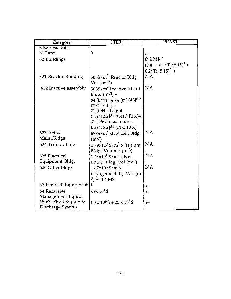
Category 6 Site Facilities 61 Land 62 Buildings
621 Reactor Building
622 Inactive assembly
623 Active Maint.Bldgs 624 Tritium Bldg.
625 Electrical Equipment Bldg. 626 Other Bldgs
63 Hot Cell Equipment 64 Radwaste Management Equip. 65-67 Fluid Supply & Discharge Svstem
0
500$/m3 Reactor Bldg. Vol (m-3) 306$/m3 Inactive Maint. Bldg. (m-3) + 84 LTFC turn (m)/431°.’ (TFC Fab.) + 21 [OHC height (m)/12.2]0.7 (OHC Fab.)+ 31 [ PFC max. radius (m)/15.2]0.7 (PFC Fab.) 698$/m” xHot Cell Bldg. tm-3> 1.79~103 $/m’ x Tritium Bldg. Volume (m-3) 1.45~103 $/m” x Elec. Equip. Bldg. Vol (m-3) 1.67~103 $/m”x Cryogenic Bldg. Vol. (me 3) + 104 M$ 0 69x l@ $
PCAST
&2M$’ (0.4 + 0.4*(R/8.15)3 + 0.2*(R/8.15)* ) NA
NA
NA
NA
NA
,NA
t
t
t
171