technical 16mm multi-pitch tape feeder t47175801 rev. b · · 2017-01-04page 3 16mm multi-pitch...
TRANSCRIPT

Page 1
16mm Multi-Pitch Tape Feeder T47175801 Rev. BTECHNICAL PUBLICATIONS
This Document Supports Assembly 47175801 Rev. A
Page 2
T47175801 Rev. B 16mm Multi-Pitch Tape FeederTECHNICAL PUBLICATIONS
This Document Supports Assembly 47175801 Rev. A
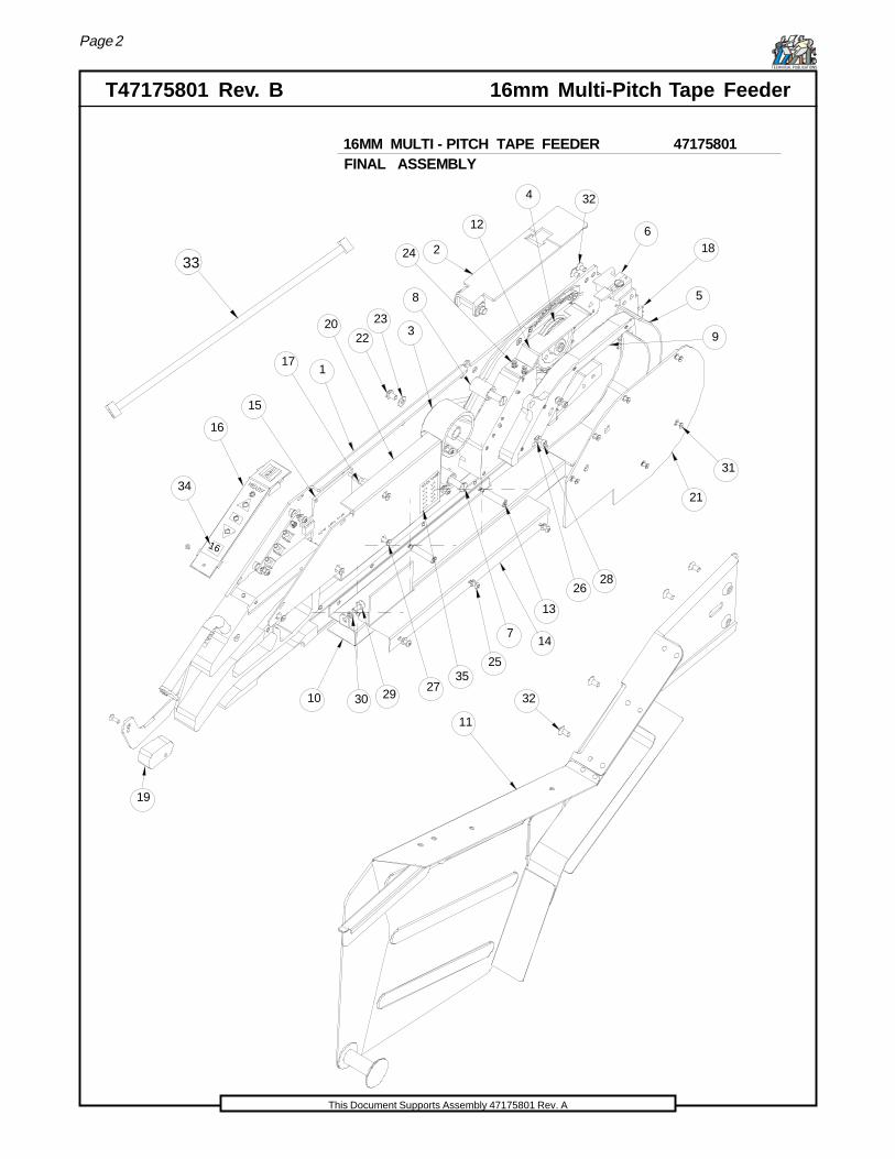
FINAL ASSEMBLY16MM MULTI - PITCH TAPE FEEDER 47175801
11
32
33
19
10 30 2927
25
714
13
2628
21
31
5
9
618
324
12
224
8
323
2220
117
16
34
35
15
PITCH C
HART
X = X
X = X
X = X
X = X
X = X
X = X
X = X
X = X
X = X
X = X
16

Page 3
16mm Multi-Pitch Tape Feeder T47175801 Rev. BTECHNICAL PUBLICATIONS
This Document Supports Assembly 47175801 Rev. A
FINAL ASSEMBLY
16MM MULTI - PITCH TAPE FEEDER 47175801
BILL OF MATERIALSNO.
1
2
3
4
5
6
7
8
9
10
11
12
13
14
15
16
17
18
19
20
21
22
23
24
25
26
27
28
29
30
31
32
33
34
35
TYPE
ASSEMBLY
ASSEMBLY
ASSEMBLY
ASSEMBLY
ASSEMBLY
ASSEMBLY
PART
PART
PART
PART
PART
PART
PART
PART
PART
PART
PART
PART
PART
PART
PART
PART
PART
ASSEMBLY
PART
PART
PART
PART
PART
PART
PART
ASSEMBLY
ASSEMBLY
PART
PART
QTY
1
1
1
1
1
1
2
2
1
1
1
1
1
1
2
1
1
1
1
3
1
3
1
8
8
10
7
2
1
1
8
8
1
1
1
16MM FEEDER SIZE STICKER
DESCRIPTION
24mm TUW ASSY
MPU CONTROLLER
BOARD COVER
BASE PLATE GENERIC ASSY
16mm TAPE WINDOW ASSY
SWD MAIN DRIVE ASSY
16 / 24 FRONT FENDER
WINDOW LATCH ASSY
TAPE ROLLER PIN
INPUT ROLLER
16mm OUTSIDE TAPE RAIL
16 / 24 LOWER EXIT TUBE
16 / 24 TAIL SECTION
CONTROL PANEL ASSY
16 / 24 BELT GUARD
WIRE GUIDE STAND
WIRE GUIDE LONG
BOARD STANDOFF STUD
LATCH HANDLE ASSY
M4 FLAT WASHER
M4 x 08 - SSLHCS
OUTSIDE COVER
M3 x 05 - FHCS
M3 x 06 - BHCS
M3 x 08 - FHCS
M3 X 08 - SHCS
M4 x 08 - SHCS
M2.5 x 05 - FHCS
M4 x 08 - FHCS
M4 LOCK WASHER
M3 LOCK WASHER
SENSOR CABLE
I / O CABLE
PITCH LABEL
PART NUMBER
040A - S10
042A - S09
103A - S12
042A - S03
042C - 011
040A - S00
103C - 034
042A - S11
111C - 032
040C - 001
040C - 021
109C - 067
048A - 002
040A - S12
F12065
042C - 018
043A - S13
042C - 004
040C - 041
040C - 040
040C - 003
048A - 009
048A - 010
109C - 019
80031701
80028907
80029806
80055605
80028901
80026903
80055607
80047002
80029001
109C - 020
M3 X 08 - SHCS
Page 4
T47175801 Rev. B 16mm Multi-Pitch Tape FeederTECHNICAL PUBLICATIONS
This Document Supports Assembly 47175801 Rev. A
32
31
22
32
22
27
22
23
27
27
24
26 25
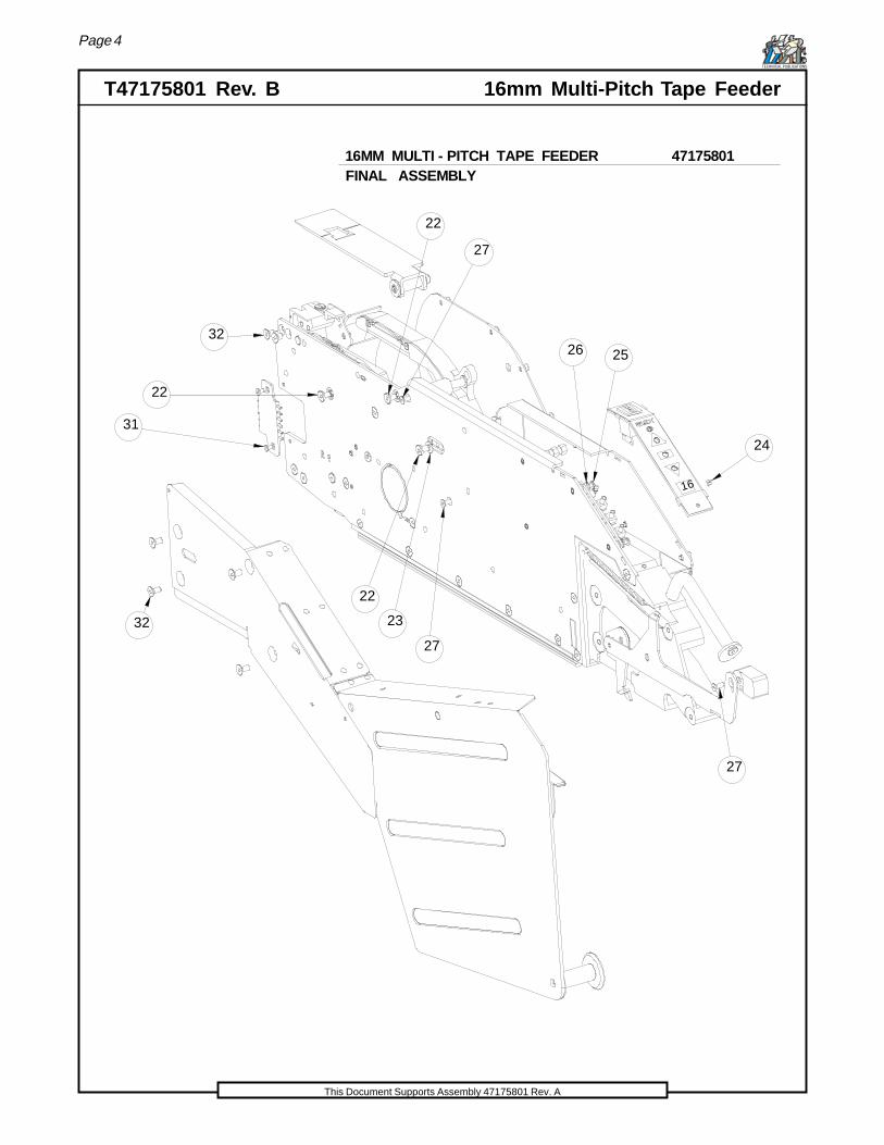
FINAL ASSEMBLY16MM MULTI - PITCH TAPE FEEDER 47175801
16

Page 5
16mm Multi-Pitch Tape Feeder T47175801 Rev. BTECHNICAL PUBLICATIONS
This Document Supports Assembly 47175801 Rev. A
FINAL ASSEMBLY16MM MULTI - PITCH TAPE FEEDER 47175801
BILL OF MATERIALS
1
TYPE PART NUMBER DESCRIPTION QTY
ASSEMBLY 040A - S10
NO.
1
2
3
4
5
6
7
8
9
10
11
12
13
14
15
16
17
18
19
20
21
22
23
ASSEMBLY
ASSEMBLY
ASSEMBLY
ASSEMBLY
ASSEMBLY
1
1
1
1
1
2
2
1
1
042A - S09
103A - S12
042A - S03
042C - 011
040A - S00
103C - 034
042A - S11
24mm TUW ASSY
PART
PART
PART
PART
PART
PART
PART 111C - 032
040C - 001
040C - 021
PART
PART
PART
1
1
1
1
2
1
1
1
1
PART
3
1
MPU CONTROLLER
BOARD COVER
24
25
PART
PART
109C - 067 3
1
048A - 002
040A - S12
PART
8
8
26
27
BASE PLATE GENERIC ASSY
16mm TAPE WINDOW ASSY
SWD MAIN DRIVE ASSY
16 / 24 FRONT FENDER
WINDOW LATCH ASSY
TAPE ROLLER PINF12065PART
PART
INPUT ROLLERPART
16mm OUTSIDE TAPE RAIL
16 / 24 LOWER EXIT TUBE042C - 018
043A - S13ASSEMBLY 16 / 24 TAIL SECTION
042C - 004
040C - 041
040C - 040
CONTROL PANEL ASSY
16 / 24 BELT GUARD
WIRE GUIDE STAND
WIRE GUIDE LONG
BOARD STANDOFF STUD040C - 003
LATCH HANDLE ASSY
M4 FLAT WASHER
M4 x 08 - SSLHCS
OUTSIDE COVER
28
29
30
31
32
33
PART
PART
PART
PART
PART
PART
PART
10
7
2
1
1
8
8
M3 x 05 - FHCS
M3 x 06 - BHCS
M3 x 08 - FHCS
M3 X 08 - SHCS
M4 x 08 - SHCS
M2.5 x 05 - FHCS
M4 x 08 - FHCS
M4 LOCK WASHER
M3 LOCK WASHER
ASSEMBLY
1048A - 009ASSEMBLY SENSOR CABLE
048A - 010 I / O CABLE
34 PART 109C - 019 1
80031701
80028907
80029806
80055605
80028901
80026903
80055607
80047002
80029001
35 PART 109C - 020 1
16MM FEEDER SIZE STICKER
PITCH LABEL
M3 X 08 - SHCS
Page 6
T47175801 Rev. B 16mm Multi-Pitch Tape FeederTECHNICAL PUBLICATIONS
This Document Supports Assembly 47175801 Rev. A
12
3
4
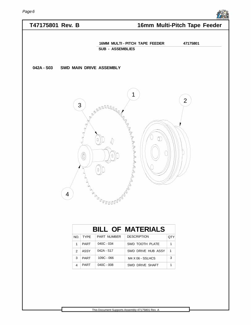
042A - S03 SWD MAIN DRIVE ASSEMBLY
BILL OF MATERIALS
1
TYPE PART NUMBER DESCRIPTION QTYNO.
1
2
3
ASSY
PART
PART
PART
3
4
042A - S17
1
1
M4 X 06 - SSLHCS
040C - 034 SWD TOOTH PLATE
109C - 066
SWD DRIVE SHAFT040C - 008
SWD DRIVE HUB ASSY
SUB - ASSEMBLIES16MM MULTI - PITCH TAPE FEEDER 47175801

Page 7
16mm Multi-Pitch Tape Feeder T47175801 Rev. BTECHNICAL PUBLICATIONS
This Document Supports Assembly 47175801 Rev. A
1
23
SUB - ASSEMBLIES
BILL OF MATERIALS
1
TYPE PART NUMBER DESCRIPTION QTY
042C - 022
NO.
1
2
3
1
2
040C - 039
M2.5 x 05 FHCS
PART
PART
PART
16MM TAPE RAIL
TAPE SUPPORT OUT
16MM MULTI - PITCH TAPE FEEDER 47175801
80047002
042A - S11 16MM OUTSIDE TAPE RAIL ASSEMBLY
Page 8
T47175801 Rev. B 16mm Multi-Pitch Tape FeederTECHNICAL PUBLICATIONS
This Document Supports Assembly 47175801 Rev. A
BILL OF MATERIALS
1
TYPE PART NUMBER DESCRIPTION QTY
103A - S13
NO.
1
2 1
PART3
4
5
PART
PART
ASSY
109C - 021
PART
PART
PART
103C - 032
0002 - 064
109C - 025
1
1
1
6
7
8
1
1
1
9
PART
PART 109C - 036
M3 X 06 - BHCS
103C - 024
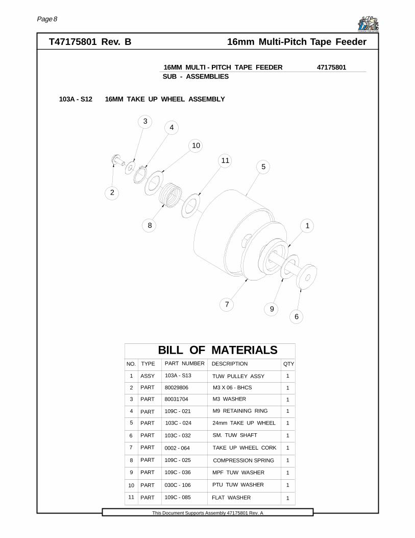
TUW PULLEY ASSY
M3 WASHER
M9 RETAINING RING
24mm TAKE UP WHEEL
TAKE UP WHEEL CORK
1
1030C - 106PART10
11 PART 109C - 085 1FLAT WASHER
MPF TUW WASHER
PTU TUW WASHER
SM. TUW SHAFT
80029806
80031704
103A - S12 16MM TAKE UP WHEEL ASSEMBLY
COMPRESSION SPRING
SUB - ASSEMBLIES16MM MULTI - PITCH TAPE FEEDER 47175801
1
2
34
5
6
7
8
9
10
11

Page 9
16mm Multi-Pitch Tape Feeder T47175801 Rev. BTECHNICAL PUBLICATIONS
This Document Supports Assembly 47175801 Rev. A
1
2
4
3
BILL OF MATERIALS
1
TYPE PART NUMBER DESCRIPTION QTY
042A - S23
NO.
1
2
3
1042C - 030PART
PART
4 PART WINDOW E - RING 1
1
ASSEMBLY 16mm WINDOW/DEFLECTOR
040C - 103 WINDOW SPRING
040C - 102
1624mm WINDOW SHAFT
042A - S09 16MM TAPE WINDOW ASSEMBLY
SUB - ASSEMBLIES16MM MULTI - PITCH TAPE FEEDER 47175801
Page 10
T47175801 Rev. B 16mm Multi-Pitch Tape FeederTECHNICAL PUBLICATIONS
This Document Supports Assembly 47175801 Rev. A
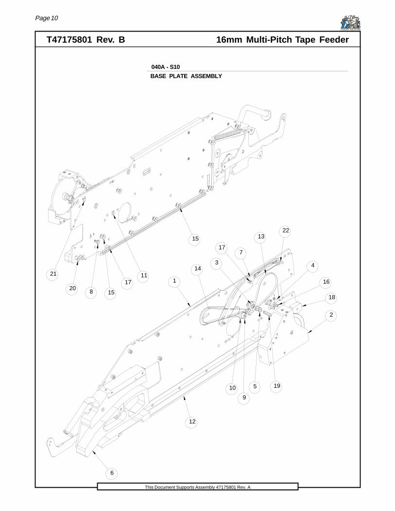
040A - S10
BASE PLATE ASSEMBLY
8
11
15
1720
15
21
6
1 16
2
3 4
7
9
10
12
13
14
5 19
18
22
17
Page 11
16mm Multi-Pitch Tape Feeder T47175801 Rev. BTECHNICAL PUBLICATIONS
This Document Supports Assembly 47175801 Rev. A
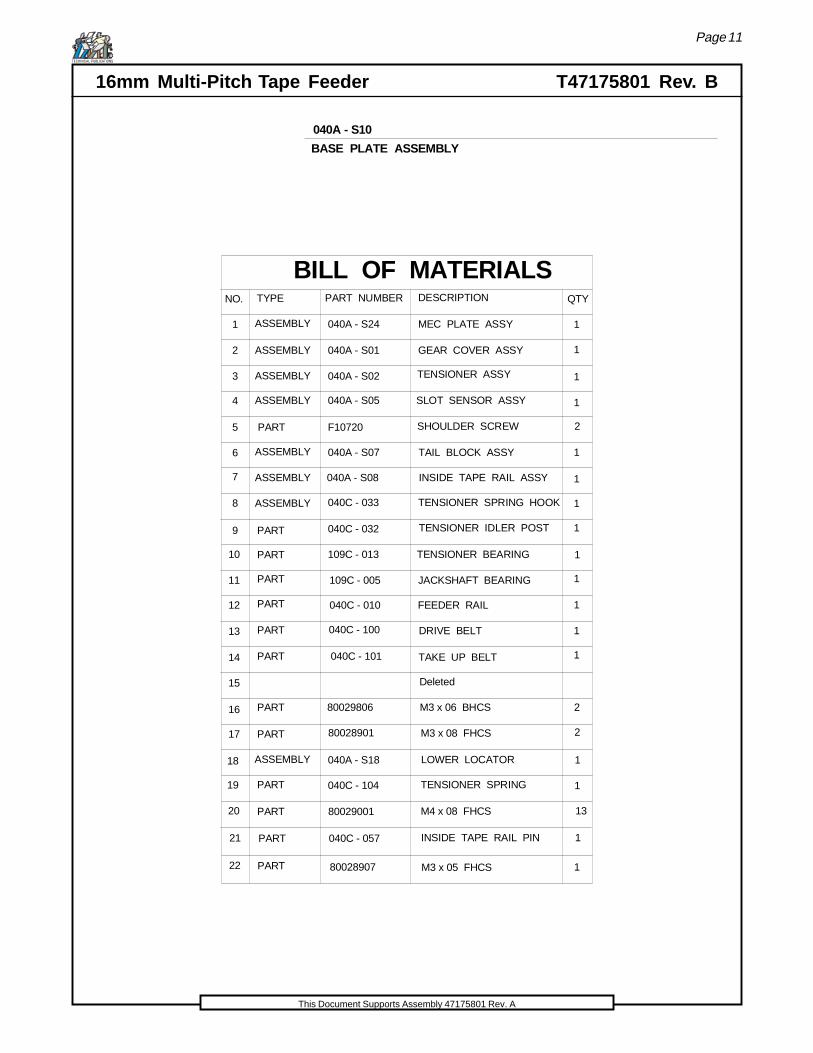
BILL OF MATERIALS
1
TYPE PART NUMBER DESCRIPTION QTY
040A - S24
NO.
1
2
3
4
5
6
7
8
9
10
11
12
13
14
15
ASSEMBLY
PART
PART
PART
PART
PART
040A - S01
040A - S02
040A - S05
1
1
1
1
1
1
1
1
1
16
17
2
2
PART
PART
PART
040A - S07 1
040C - 033
109C - 005
TENSIONER BEARING109C - 013
040C - 010
ASSEMBLY
ASSEMBLY
ASSEMBLY GEAR COVER ASSY
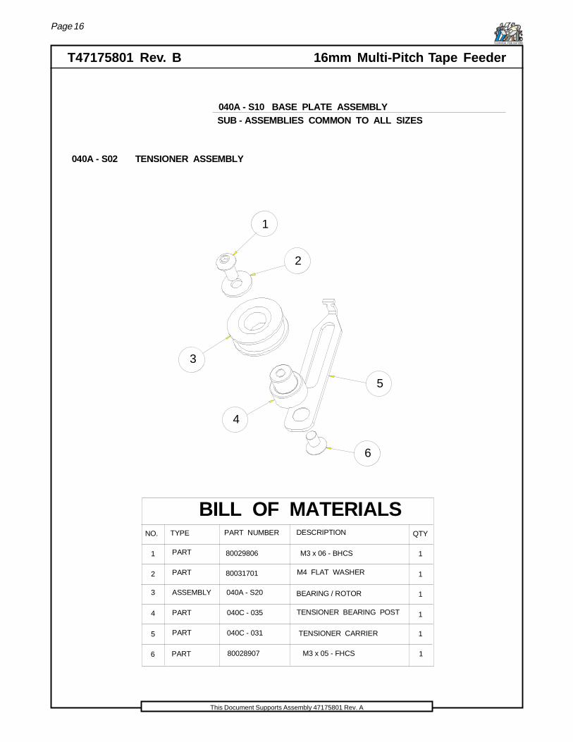
ASSEMBLY TENSIONER ASSY
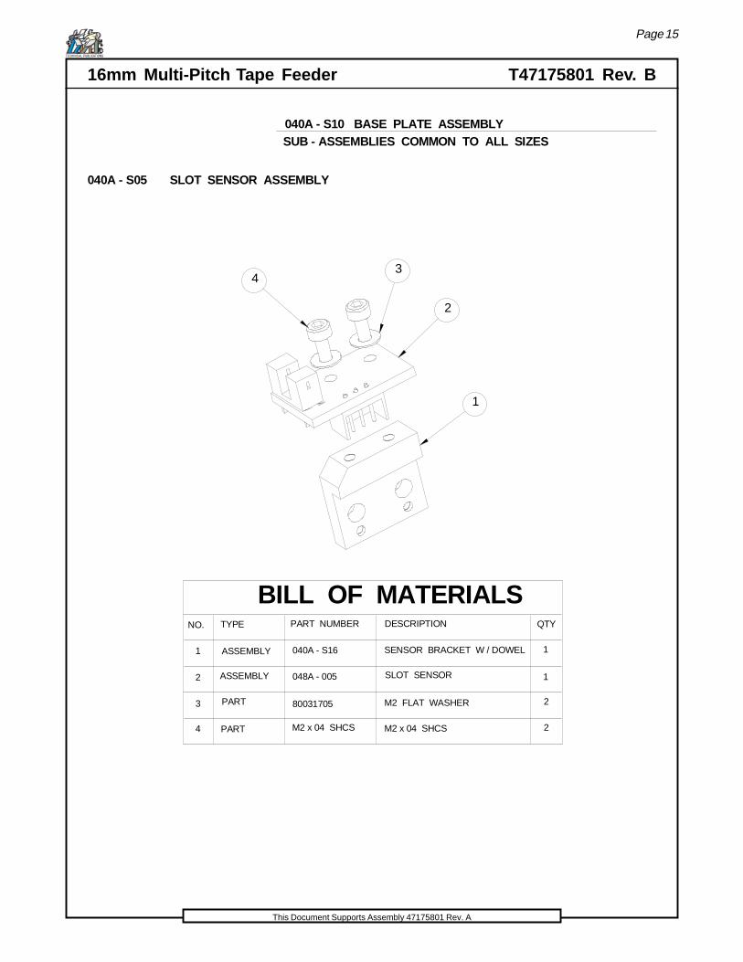
SLOT SENSOR ASSY
PART F10720 SHOULDER SCREW
TAIL BLOCK ASSY
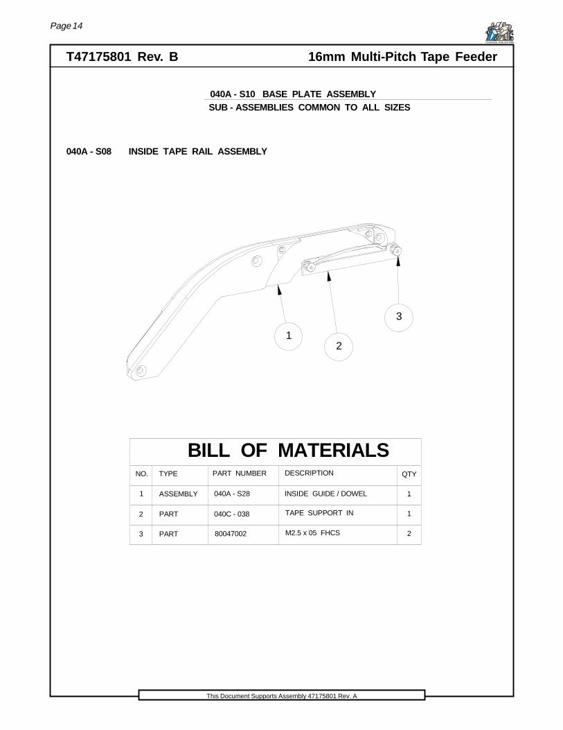
040A - S08 INSIDE TAPE RAIL ASSY 1
2
TENSIONER SPRING HOOK
TENSIONER IDLER POST 1040C - 032
JACKSHAFT BEARING
FEEDER RAIL
DRIVE BELT
TAKE UP BELT
040C - 100
040C - 101
ASSEMBLY MEC PLATE ASSY
ASSEMBLY
118 ASSEMBLY LOWER LOCATOR040A - S18
80029806
80028901
1
13
19
20
PART
PART
040C - 104
80029001
TENSIONER SPRING
21 PART 1INSIDE TAPE RAIL PIN040C - 057
22 PART M3 x 05 FHCS 1
M4 x 08 FHCS
M3 x 08 FHCS
M3 x 06 BHCS
Deleted
80028907
040A - S10
BASE PLATE ASSEMBLY
Page 12
T47175801 Rev. B 16mm Multi-Pitch Tape FeederTECHNICAL PUBLICATIONS
This Document Supports Assembly 47175801 Rev. A
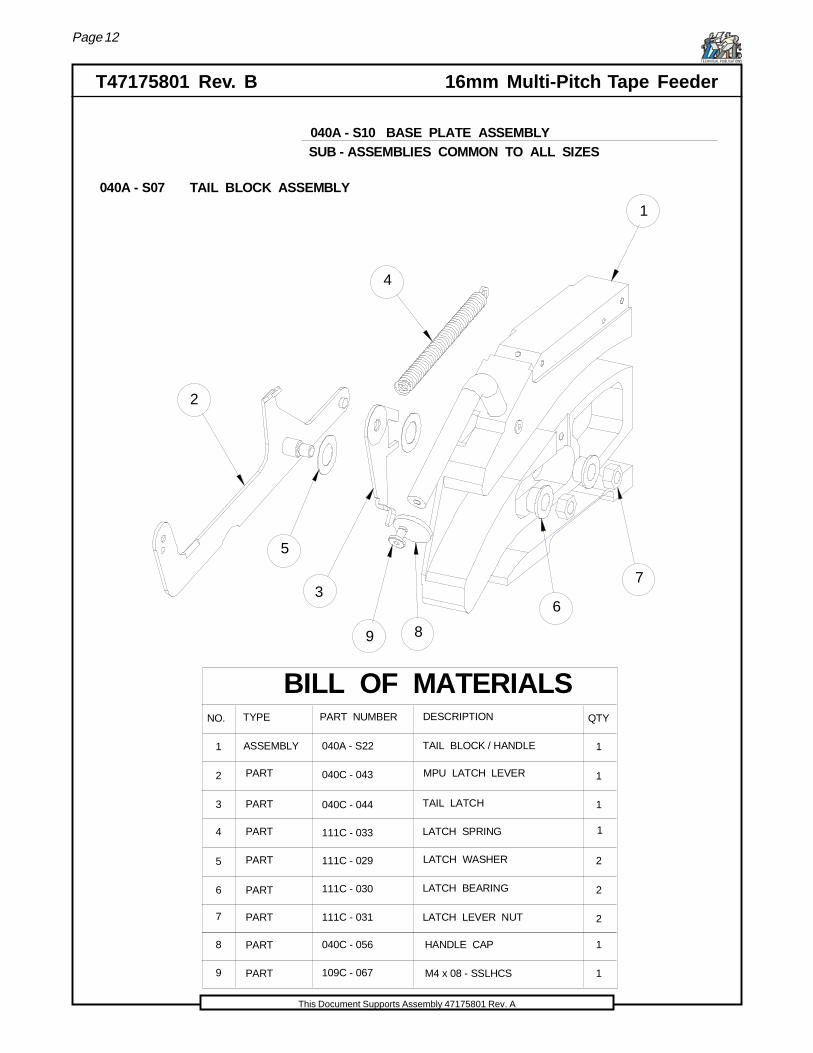
BILL OF MATERIALS
1
TYPE PART NUMBER DESCRIPTION QTY
ASSEMBLY 040A - S22
NO.
1
2
3
4
5
6
7
1
1
1
2
2
2
040C - 043
040C - 044
111C - 033
111C - 029
111C - 030
LATCH LEVER NUT
TAIL BLOCK / HANDLE
PART
PART
PART
PART
PART
PART
TAIL LATCH
LATCH SPRING
LATCH WASHER
LATCH BEARING
111C - 031
8
9
PART
PART
040C - 056
109C - 067
MPU LATCH LEVER
1
M4 x 08 - SSLHCS
HANDLE CAP
1
1
2
3
4
5
6
7
89
040A - S07 TAIL BLOCK ASSEMBLY
040A - S10 BASE PLATE ASSEMBLYSUB - ASSEMBLIES COMMON TO ALL SIZES
Page 13
16mm Multi-Pitch Tape Feeder T47175801 Rev. BTECHNICAL PUBLICATIONS
This Document Supports Assembly 47175801 Rev. A
1
2
3 4
56
7
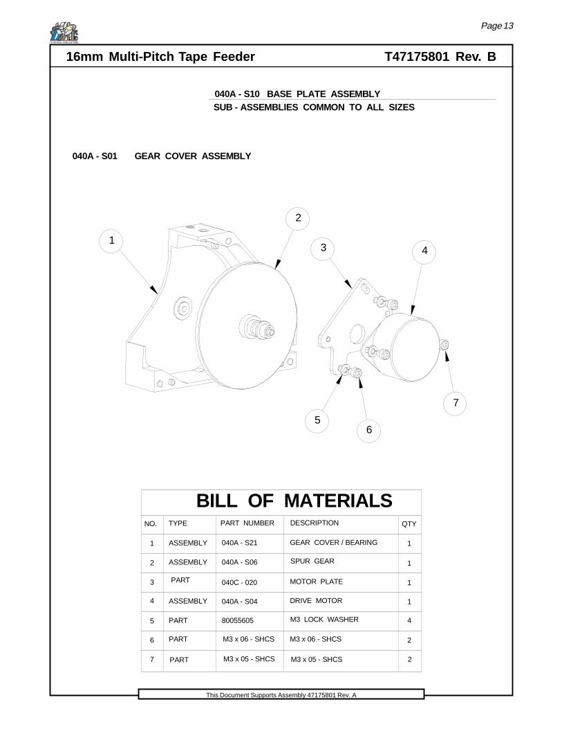
BILL OF MATERIALS
1
TYPE PART NUMBER DESCRIPTION QTY
ASSEMBLY 040A - S21
NO.
1
2
3
4
5
6
ASSEMBLY
ASSEMBLY
1
1
1
4
2
040A - S06
040C - 020
040A - S04
PART
GEAR COVER / BEARING
SPUR GEAR
PART MOTOR PLATE
DRIVE MOTOR
M3 LOCK WASHER
M3 x 06 - SHCSM3 x 06 - SHCS
80055605
PART
PART M3 x 05 - SHCS M3 x 05 - SHCS 27
040A - S01 GEAR COVER ASSEMBLY
040A - S10 BASE PLATE ASSEMBLYSUB - ASSEMBLIES COMMON TO ALL SIZES
Page 14
T47175801 Rev. B 16mm Multi-Pitch Tape FeederTECHNICAL PUBLICATIONS
This Document Supports Assembly 47175801 Rev. A
12
3
BILL OF MATERIALS
1
TYPE PART NUMBER DESCRIPTION QTY
040A - S28
NO.
1
2
3
1
2
040C - 038PART
PART
TAPE SUPPORT IN
M2.5 x 05 FHCS
ASSEMBLY INSIDE GUIDE / DOWEL
80047002
040A - S08 INSIDE TAPE RAIL ASSEMBLY
040A - S10 BASE PLATE ASSEMBLYSUB - ASSEMBLIES COMMON TO ALL SIZES
Page 15
16mm Multi-Pitch Tape Feeder T47175801 Rev. BTECHNICAL PUBLICATIONS
This Document Supports Assembly 47175801 Rev. A
1
2
34
BILL OF MATERIALS
1
TYPE PART NUMBER DESCRIPTION QTY
ASSEMBLY
040A - S16
NO.
1
2
3
4
1
2
2
048A - 005
PART
PART
SLOT SENSOR
M2 FLAT WASHER
M2 x 04 SHCSM2 x 04 SHCS
SENSOR BRACKET W / DOWELASSEMBLY
80031705
040A - S05 SLOT SENSOR ASSEMBLY
040A - S10 BASE PLATE ASSEMBLYSUB - ASSEMBLIES COMMON TO ALL SIZES
Page 16
T47175801 Rev. B 16mm Multi-Pitch Tape FeederTECHNICAL PUBLICATIONS
This Document Supports Assembly 47175801 Rev. A
040A - S10 BASE PLATE ASSEMBLYSUB - ASSEMBLIES COMMON TO ALL SIZES
BILL OF MATERIALS
1
TYPE PART NUMBER DESCRIPTION QTYNO.
1
2
3
4
5
1
1
1
1
040A - S20
040C - 035
040C - 031
BEARING / ROTOR
PART
PART
M3 x 06 - BHCS
M4 FLAT WASHER
TENSIONER CARRIERPART
TENSIONER BEARING POSTPART
ASSEMBLY
1
2
3
4
5
6
16 PART M3 x 05 - FHCS
80029806
80031701
80028907
040A - S02 TENSIONER ASSEMBLY
Page 17
16mm Multi-Pitch Tape Feeder T47175801 Rev. BTECHNICAL PUBLICATIONS
This Document Supports Assembly 47175801 Rev. A
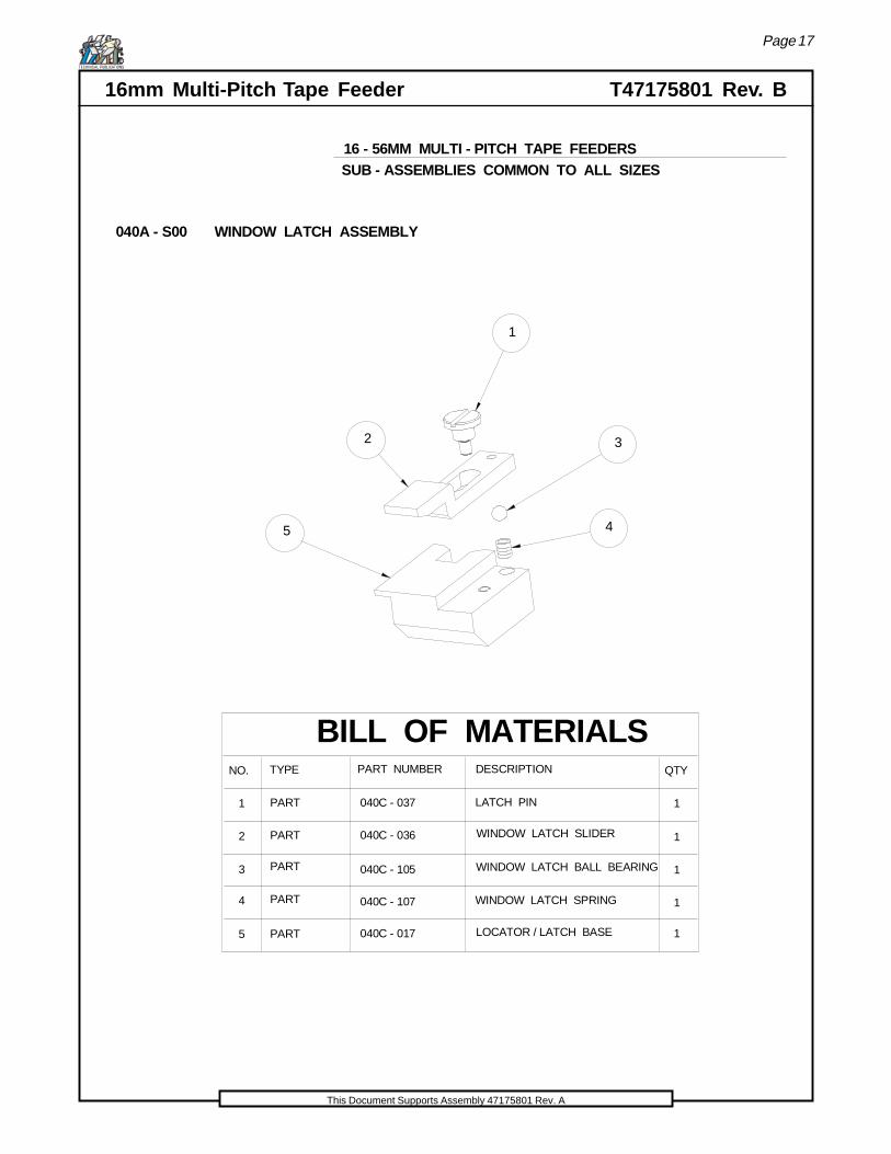
BILL OF MATERIALS
1
TYPE PART NUMBER DESCRIPTION QTY
040C - 037
NO.
1
2
3
4
5
1
1
1
1
040C - 036
040C - 105
040C - 107
040C - 017
WINDOW LATCH SPRING
LOCATOR / LATCH BASE
PART
PART
PART
PART
PART
WINDOW LATCH BALL BEARING
WINDOW LATCH SLIDER
LATCH PIN
16 - 56MM MULTI - PITCH TAPE FEEDERS
3
1
2
45
040A - S00 WINDOW LATCH ASSEMBLY
SUB - ASSEMBLIES COMMON TO ALL SIZES

Page 18
T47175801 Rev. B 16mm Multi-Pitch Tape FeederTECHNICAL PUBLICATIONS
This Document Supports Assembly 47175801 Rev. A
1
2
3
BILL OF MATERIALS
1
TYPE PART NUMBER DESCRIPTION QTY
048A - 011
NO.
1
2
3
1
1
040C - 005
040C - 006
PART
PART
PART CONTROL PANEL PLATE
OVERLAY LABEL
PITCH SWITCH
040A - S12 CONTROL PANEL ASSEMBLY
16 - 56MM MULTI - PITCH TAPE FEEDERSSUB - ASSEMBLIES COMMON TO ALL SIZES
Page 19
16mm Multi-Pitch Tape Feeder T47175801 Rev. BTECHNICAL PUBLICATIONS
This Document Supports Assembly 47175801 Rev. A
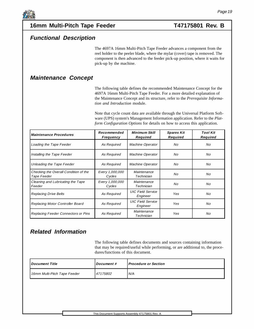
Functional Description
The 4697A 16mm Multi-Pitch Tape Feeder advances a component from thereel holder to the peeler blade, where the mylar (cover) tape is removed. Thecomponent is then advanced to the feeder pick-up position, where it waits forpick-up by the machine.
Maintenance Concept
The following table defines the recommended Maintenance Concept for the4697A 16mm Multi-Pitch Tape Feeder. For a more detailed explanation ofthe Maintenance Concept and its structure, refer to the Prerequisite Informa-tion and Introduction module.
Note that cycle count data are available through the Universal Platform Soft-ware (UPS) system's Management Information application. Refer to the Plat-form Configuration Options for details on how to access this application.
Maintenance ProceduresRecommended
FrequencyMinimum Skill
RequiredSpares Kit Required
Tool Kit Required
Loading the Tape Feeder As Required Machine Operator No No
Installing the Tape Feeder As Required Machine Operator No No
Unloading the Tape Feeder As Required Machine Operator No No
Checking the Overall Condition of the Tape Feeder
Every 1,000,000 Cycles
Maintenance Technician
No No
Cleaning and Lubricating the Tape Feeder
Every 1,000,000 Cycles
Maintenance Technician
No No
Replacing Drive Belts As RequiredUIC Field Service
EngineerYes No
Replacing Motor Controller Board As RequiredUIC Field Service
EngineerYes No
Replacing Feeder Connectors or Pins As RequiredMaintenance Technician
Yes No
Related Information
The following table defines documents and sources containing informationthat may be required/useful while performing, or are additional to, the proce-dures/functions of this document.
Document Title Document # Procedure or Section
16mm Multi-Pitch Tape Feeder 47175802 N/A

Page 20
T47175801 Rev. B 16mm Multi-Pitch Tape FeederTECHNICAL PUBLICATIONS
This Document Supports Assembly 47175801 Rev. A
Use extreme caution when ordering motors for the tape feeders. Thereare two different 16-56mm Multi-Pitch Tape Feeder part number series.The 47178801 uses a 040A-S04 motor, and the 47178802 uses a 042A-S04 motor.The motors are not interchangeable.
Also, use extreme caution when working with the control boards becausethe part number ot the control board did not change. Do not remove anold control board (from a 47178801 feeder) and place it in the (47178802feeder), because the boards appear the same, but electronically are notinterchangeable. If this happens the board will be damaged. A controlboard from the 47178802 will work with either a 042A-S04 or a 040A-S04motor.

Page 21
16mm Multi-Pitch Tape Feeder T47175801 Rev. BTECHNICAL PUBLICATIONS
This Document Supports Assembly 47175801 Rev. A
Procedures and Adjustments
Adjustments and corrective maintenance procedures required of the customerare presented in the following subsections.
Loading the Tape Feeder
Load the 16mm Multi Pitch Tape Feeder using the following procedure.
1. Remove the plastic Reel Cap from the tail section of the tape feeder,install the tape reel, and replace the Reel Cap. Refer to the diagram tothe left.
Reel Cap
Tape Reel
Tail Section
2. Release the Tape Window by sliding the Tape Window Latch forward.Rotate the Tape Window up.
Tape WindowTape Window Latch
3. Thread the Carrier Tape through the rear channel of the feeder and thenover the top of the tape rails. Refer to the tape path below. The frontinch of the tape should be directed into the Front Tape Chute.
Tape Reel
Rear Channel
Front TapeChute
Take-UpWheel
Tape Rails

Page 22
T47175801 Rev. B 16mm Multi-Pitch Tape FeederTECHNICAL PUBLICATIONS
This Document Supports Assembly 47175801 Rev. A
4. Separate about eight inches of Cover Tape from the Carrier Tape. Peelthe Cover Tape back from the Carrier Tape, but avoid detaching itcompletely.
Cover Tape
Carrier Tape
8"
5. Pull the Cover Tape through the Tape Window.
TapeWindow
6. Align the holes in the Carrier Tape with the index wheel teeth that arevisible. Close the tape window and then secure it with the Tape Win-dow Latch.
Carrier Tape
Index WheelTeeth
7. Secure the mylar Cover Tape to the take-up wheel by tying a knot inthe end of the tape and inserting it through the slot into the take-upwheel as shown below.
Take-UpWheel
Cover Tape

Page 23
16mm Multi-Pitch Tape Feeder T47175801 Rev. BTECHNICAL PUBLICATIONS
This Document Supports Assembly 47175801 Rev. A
Installing the Tape Feeder
Install the 16mm Multi-Pitch Tape Feeder using the following procedure.
1. Push the tape feeder latch down so that it locks down. Slide the feederonto the feeder bank assembly as shown in the following illustration.
FeederLatch
GSM FeederBank Assembly
GSM FeederInterface Assembly
Slide feederup along tee slot in this direction
2. Slide the feeder in until it connects with the interface assembly.
3. Once the Status Light illuminates, signaling a firm connection betweenthe feeder and the interface, release the Feeder Latch and pull it up.This locks the feeder into its operational position.
Page 24
T47175801 Rev. B 16mm Multi-Pitch Tape FeederTECHNICAL PUBLICATIONS
This Document Supports Assembly 47175801 Rev. A
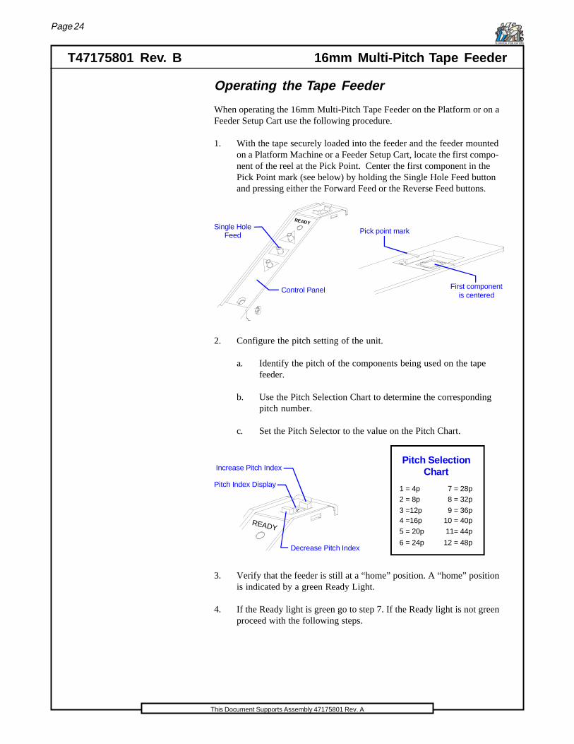
Operating the Tape Feeder
When operating the 16mm Multi-Pitch Tape Feeder on the Platform or on aFeeder Setup Cart use the following procedure.
1. With the tape securely loaded into the feeder and the feeder mountedon a Platform Machine or a Feeder Setup Cart, locate the first compo-nent of the reel at the Pick Point. Center the first component in thePick Point mark (see below) by holding the Single Hole Feed buttonand pressing either the Forward Feed or the Reverse Feed buttons.
READY
Control Panel
Single Hole Feed
First component is centered
Pick point mark
2. Configure the pitch setting of the unit.
a. Identify the pitch of the components being used on the tapefeeder.
b. Use the Pitch Selection Chart to determine the correspondingpitch number.
c. Set the Pitch Selector to the value on the Pitch Chart.
READY
Decrease Pitch Index
Increase Pitch Index
Pitch Index Display
Pitch SelectionChart
2 = 8p
3 =12p4 =16p
5 = 20p
6 = 24p
7 = 28p8 = 32p
9 = 36p10 = 40p
11= 44p
12 = 48p
1 = 4p
3. Verify that the feeder is still at a “home” position. A “home” positionis indicated by a green Ready Light.
4. If the Ready light is green go to step 7. If the Ready light is not greenproceed with the following steps.

Page 25
16mm Multi-Pitch Tape Feeder T47175801 Rev. BTECHNICAL PUBLICATIONS
This Document Supports Assembly 47175801 Rev. A
5. Perform the Single Hole Forward sequence. (Shown below)
READY
Single Hole Forward
Forward Feed
Single Hole Feed
Ready Light
a. Push the Single Hole Feed button on the Control Panel.
b. Push the Forward Feed button on the Control Panel.
6. Perform the Single Hole Reverse sequence. (Shown below)
Single Hole Reverse
Single Hole Feed
Reverse Feed
READY
Ready Light
a. Push the Single Hole Feed button on the Control Panel.
b. Push the Reverse Feed button on the Control Panel.
The Ready Light should now be green. If not repeat steps 5 and 6 again.
7. Verify that the component is still centered at the Pick Point.
Pick point mark
Verify that the first componentis still centered
Page 26
T47175801 Rev. B 16mm Multi-Pitch Tape FeederTECHNICAL PUBLICATIONS
This Document Supports Assembly 47175801 Rev. A
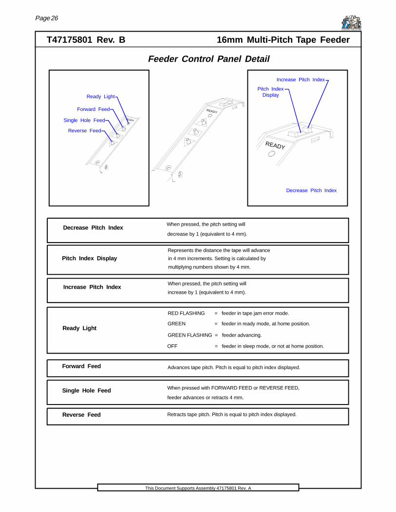
Feeder Control Panel Detail
READY
Ready Light
Forward Feed
Single Hole Feed
Reverse Feed
Ready Light
Forward Feed
Reverse Feed
Single Hole Feed
Decrease Pitch Index
Pitch Index Display
Increase Pitch Index
When pressed, the pitch setting will
decrease by 1 (equivalent to 4 mm).
Represents the distance the tape will advance
in 4 mm increments. Setting is calculated by
multiplying numbers shown by 4 mm.
When pressed, the pitch setting will
increase by 1 (equivalent to 4 mm).
Advances tape pitch. Pitch is equal to pitch index displayed.
GREEN FLASHING = feeder advancing.
When pressed with FORWARD FEED or REVERSE FEED,
feeder advances or retracts 4 mm.
Retracts tape pitch. Pitch is equal to pitch index displayed.
OFF = feeder in sleep mode, or not at home position.
GREEN = feeder in ready mode, at home position.
RED FLASHING = feeder in tape jam error mode.
READY
Decrease Pitch Index
Pitch Index Display
Increase Pitch Index
READY
Page 27
16mm Multi-Pitch Tape Feeder T47175801 Rev. BTECHNICAL PUBLICATIONS
This Document Supports Assembly 47175801 Rev. A
Pick Point Adjustment
To restore the Default Pick Point on the 16mm Multi-Pitch Tape Feeder, referto the Default Pick Point Adjustment section later in this document.
To restore the Factory Default Pick Point refer to the Factory Default PickPoint section later in this document.
To operate the 16mm Multi-Pitch Tape Feeder for specialty applications, ad-just the Default Pick Point using the following procedure.
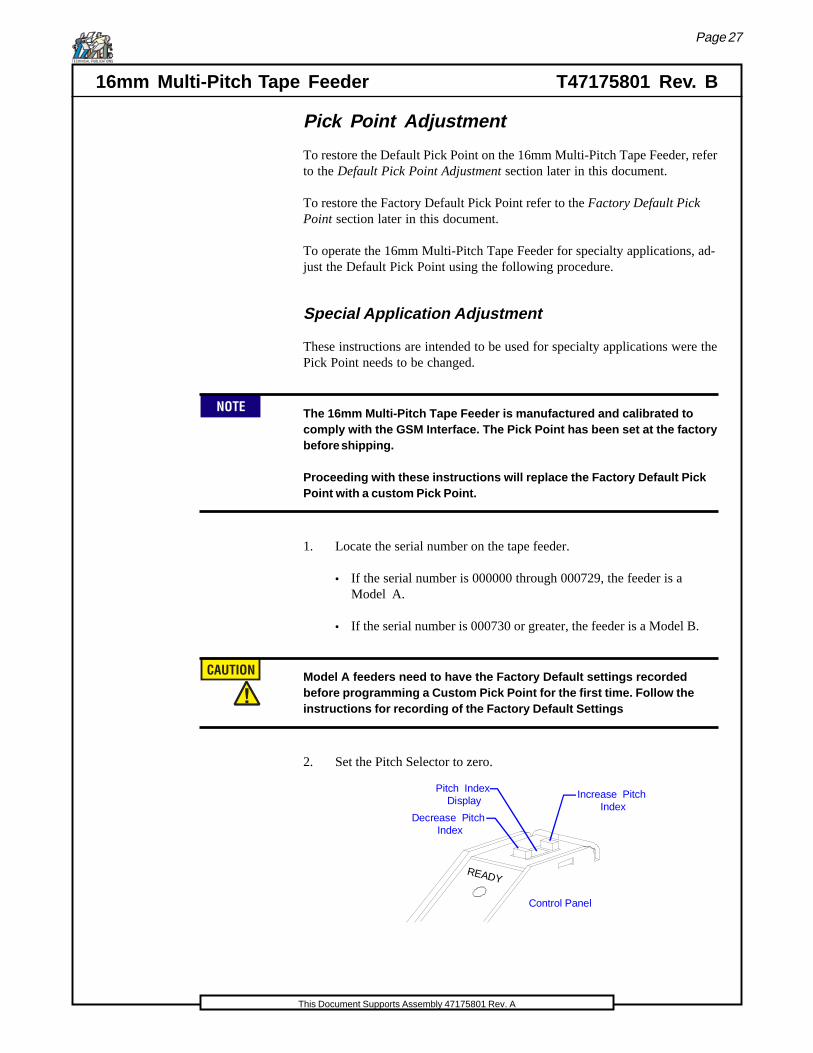
Special Application Adjustment
These instructions are intended to be used for specialty applications were thePick Point needs to be changed.
The 16mm Multi-Pitch Tape Feeder is manufactured and calibrated tocomply with the GSM Interface. The Pick Point has been set at the factorybefore shipping.
Proceeding with these instructions will replace the Factory Default PickPoint with a custom Pick Point.
1. Locate the serial number on the tape feeder.
• If the serial number is 000000 through 000729, the feeder is aModel A.
• If the serial number is 000730 or greater, the feeder is a Model B.
Model A feeders need to have the Factory Default settings recordedbefore programming a Custom Pick Point for the first time. Follow theinstructions for recording of the Factory Default Settings
2. Set the Pitch Selector to zero.
Control Panel
READY
Decrease Pitch Index
Pitch Index Display
Increase Pitch Index
Page 28
T47175801 Rev. B 16mm Multi-Pitch Tape FeederTECHNICAL PUBLICATIONS
This Document Supports Assembly 47175801 Rev. A
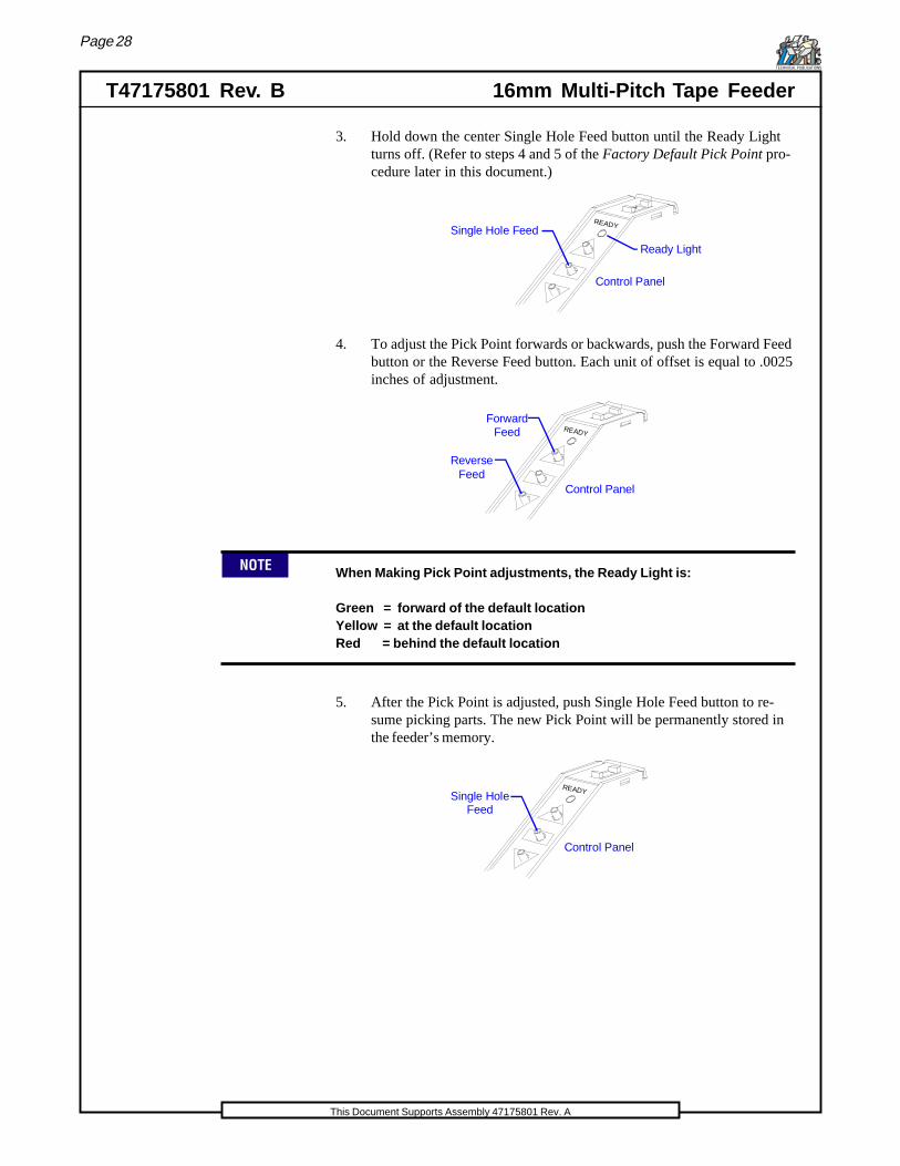
3. Hold down the center Single Hole Feed button until the Ready Lightturns off. (Refer to steps 4 and 5 of the Factory Default Pick Point pro-cedure later in this document.)
4
Control Panel
READYSingle Hole Feed
Ready Light
4. To adjust the Pick Point forwards or backwards, push the Forward Feedbutton or the Reverse Feed button. Each unit of offset is equal to .0025inches of adjustment.
Control Panel
READY
ForwardFeed
ReverseFeed
When Making Pick Point adjustments, the Ready Light is:
Green = forward of the default locationYellow = at the default locationRed = behind the default location
5. After the Pick Point is adjusted, push Single Hole Feed button to re-sume picking parts. The new Pick Point will be permanently stored inthe feeder’s memory.
Control Panel
READYSingle HoleFeed
Page 29
16mm Multi-Pitch Tape Feeder T47175801 Rev. BTECHNICAL PUBLICATIONS
This Document Supports Assembly 47175801 Rev. A
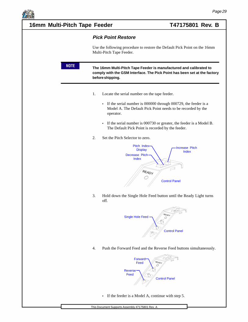
Pick Point Restore
Use the following procedure to restore the Default Pick Point on the 16mmMulti-Pitch Tape Feeder.
The 16mm Multi-Pitch Tape Feeder is manufactured and calibrated tocomply with the GSM Interface. The Pick Point has been set at the factorybefore shipping.
1. Locate the serial number on the tape feeder.
• If the serial number is 000000 through 000729, the feeder is aModel A. The Default Pick Point needs to be recorded by theoperator.
• If the serial number is 000730 or greater, the feeder is a Model B.The Default Pick Point is recorded by the feeder.
2. Set the Pitch Selector to zero.
Control Panel
READY
Decrease Pitch Index
Pitch Index Display
Increase Pitch Index
3. Hold down the Single Hole Feed button until the Ready Light turnsoff.
4
Control Panel
READYSingle Hole Feed
4. Push the Forward Feed and the Reverse Feed buttons simultaneously.
Control Panel
READY
ForwardFeed
ReverseFeed
• If the feeder is a Model A, continue with step 5.
Page 30
T47175801 Rev. B 16mm Multi-Pitch Tape FeederTECHNICAL PUBLICATIONS
This Document Supports Assembly 47175801 Rev. A
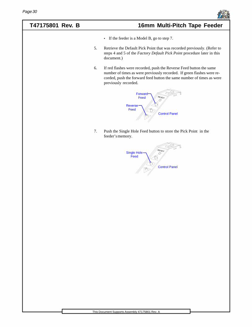
• If the feeder is a Model B, go to step 7.
5. Retrieve the Default Pick Point that was recorded previously. (Refer tosteps 4 and 5 of the Factory Default Pick Point procedure later in thisdocument.)
6. If red flashes were recorded, push the Reverse Feed button the samenumber of times as were previously recorded. If green flashes were re-corded, push the forward feed button the same number of times as werepreviously recorded.
Control Panel
READY
ForwardFeed
ReverseFeed
7. Push the Single Hole Feed button to store the Pick Point in thefeeder’s memory.
Control Panel
READYSingle HoleFeed

Page 31
16mm Multi-Pitch Tape Feeder T47175801 Rev. BTECHNICAL PUBLICATIONS
This Document Supports Assembly 47175801 Rev. A
Factory Default Pick Point
Use the following procedure to set the Factory Default Pick-Point on the16mm Multi-Pitch Tape Feeder. These instructions are intended to be usedafter replacing a Motor Controller Board, Slot Sensor Assembly, or adjustingthe feeder Pick Point.
The 16mm Multi-Pitch Tape Feeder is manufactured and calibrated tocomply with the GSM Interface. The Pick Point has been set at the factorybefore shipping.
Proceeding with these instructions will replace the Factory Pick Pointsetting.
1. Locate the serial number on the tape feeder.
• If the serial number is 000000 through 000729, the feeder is aModel A. The Default Pick Point needs to be recorded by theoperator.
• If the serial number is 000730 or greater, the feeder is a Model B.The Default Pick Point is recorded by the feeder.
2. Set the Pitch Selector to zero.
If the tape feeder is a Model A, go to step 4.
If the tape feeder is a Model B, continue with the following steps.
3. Increase or decrease the Pitch Selector of the feeder to setting 13. Thenew Factory Default Pick Point will be permanently stored in the feed-ers memory. Skip to step 6.
Control Panel
READY
Decrease Pitch Index
Pitch Index Display
Increase Pitch Index

Page 32
T47175801 Rev. B 16mm Multi-Pitch Tape FeederTECHNICAL PUBLICATIONS
This Document Supports Assembly 47175801 Rev. A
4. Hold down the Single Hole feed button until the Ready Light turns off.Note the color of the LED and how many times it flashes. The countnumber will indicate the Default Pick Point.
4
Control Panel
READYSingle Hole Feed
5. Record the number and color of the flashes in a safe place. This numberis needed to restore the Pick Point. (Refer to the Restore Pick Pointprocedure earlier in this manual.)
6. Press the center Single Hole Feed button. The new Factory Default PickPoint will be permanently stored in the feeder’s memory.
4
Control Panel
READYSingle Hole Feed
Unloading the Tape Feeder
Unload the 16mm Multi-Pitch Tape Feeder using the following procedure.
1. Remove the feeder from the Feeder Bank Assembly. Follow, in reverseorder, the steps in the Installing the Tape Feeder procedure.
2. Place the feeder on its side with the Take-up Wheel facing upwards.
3. Release the tape window latch and open the tape window.
4. Unwind about eight inches of cover tape from the Take-up Wheel andcut it from the rest of the tape wound up on the wheel.
5. Pull back on the carrier tape until there is about eight inches of tapewithout components exposed and tear off the carrier tape. Pull the ex-cess cover tape off of the Take-up Wheel and remove the excess carriertape from the Tape Exit Guide.
6. Clear any loose components from the peeler and scrap guide.
Page 33
16mm Multi-Pitch Tape Feeder T47175801 Rev. BTECHNICAL PUBLICATIONS
This Document Supports Assembly 47175801 Rev. A
Feeder Maintenance
Checking the Overall Condition of the TapeFeeder
Tape feeders require periodic inspection as prescribed in the MaintenanceConcept table. Replace worn or defective parts as necessary. Inspect theoverall condition of the tape feeder using the following procedure.
1. After every reel of components, clean any contamination from the tapewindow.
2. Check the Main Drive wheel for chipped or broken pins.
3. Check the I/O Assembly for broken or damaged electrical pins. Formore information, refer to the Replacing the Feeder Connector Assem-bly procedure in this module.
Lubricating the Tape Feeder
Clean and lubricate the 16mm Multi-Pitch Tape Feeder using the followingprocedure.
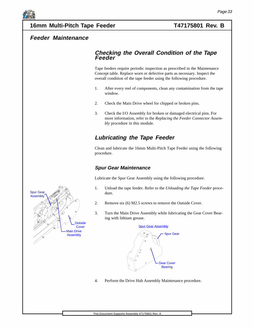
Spur Gear Maintenance
Lubricate the Spur Gear Assembly using the following procedure.
1. Unload the tape feeder. Refer to the Unloading the Tape Feeder proce-dure.
2. Remove six (6) M2.5 screws to remove the Outside Cover.
Main DriveAssembly
Outside Cover
Spur GearAssembly
3. Turn the Main Drive Assembly while lubricating the Gear Cover Bear-ing with lithium grease.
Gear CoverBearing
Spur Gear
Spur Gear Assembly
4. Perform the Drive Hub Assembly Maintenance procedure.

Page 34
T47175801 Rev. B 16mm Multi-Pitch Tape FeederTECHNICAL PUBLICATIONS
This Document Supports Assembly 47175801 Rev. A
Drive Hub Assembly Maintenance
Perform Drive Hub Assembly maintenance using the following procedure.
1. Remove six M2.5 screws to remove the Outside Cover.
2. Release the Tensioner Spring (as shown below.)
Gear CoverAssembly
TensionerSpring
3. Remove two M3 screws to remove the Outside Tape Rail Assembly.
Outside Tape Rail Assembly
Belt Guard
Main DriveAssembly
(2) M3 Screws
M4 Screw
(2) M3 Screws
Page 35
16mm Multi-Pitch Tape Feeder T47175801 Rev. BTECHNICAL PUBLICATIONS
This Document Supports Assembly 47175801 Rev. A
4. Remove two M3 screws to remove the Belt Guard. (See above dia-gram.)
5. Remove one M4 screw from the Main Drive Assembly. (See above dia-gram.)
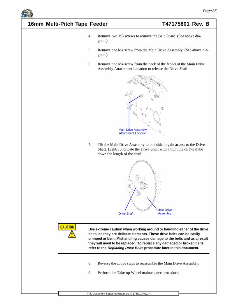
6. Remove one M4 screw from the back of the feeder at the Main DriveAssembly Attachment Location to release the Drive Shaft.
Main Drive AssemblyAttachment Location
7. Tilt the Main Drive Assembly to one side to gain access to the DriveShaft. Lightly lubricate the Drive Shaft with a thin line of Duralubedown the length of the shaft.
Drive ShaftMain DriveAssembly
Use extreme caution when working around or handling either of the drivebelts, as they are delicate elements. These drive belts can be easilycrimped or bent. Mishandling causes damage to the belts and as a resultthey will need to be replaced. To replace any damaged or broken beltsrefer to the Replacing Drive Belts procedure later in this document.
8. Reverse the above steps to reassemble the Main Drive Assembly.
9. Perform the Take-up Wheel maintenance procedure.

Page 36
T47175801 Rev. B 16mm Multi-Pitch Tape FeederTECHNICAL PUBLICATIONS
This Document Supports Assembly 47175801 Rev. A
Take-Up Wheel Maintenance
1. Decrease belt tension by loosening the M4 screw on the back of thefeeder at the Take-up Wheel Attachment Location. Do not removescrew.
Take-Up WheelAttachment Location
2. Remove one M3 screw to remove Take-up Wheel Shaft. (Refer to thediagram below.)
Take-Up WheelShaft
Take-UpWheel
M3Screw
3. Lightly lubricate the Take-up Wheel Shaft with a thin line of Duralubelubricant down the length of the shaft .
4. Reinstall the Take-up Wheel by reversing the above procedure.
Take- Up Wheel Belt Tensioning
1. Apply upward pressure of approximately 2 to 4 lbs to the Belt Ten-sioner screw, and rotate Take-up Wheel to confirm belt engagement.
TensionerAssembly
TensionerScrew
2. Tighten the Tensioner screw. Be sure not to apply excessive force totension the belt. The belt should be just tight enough to prevent slip-page without causing excessive drag.
3. Replace the Outside Cover.

Page 37
16mm Multi-Pitch Tape Feeder T47175801 Rev. BTECHNICAL PUBLICATIONS
This Document Supports Assembly 47175801 Rev. A
Replacing the Feeder Connector Assembly
The I/O, Sensor Cable, or Probe Assemblies (pogo pins) require periodic re-placement as prescribed in the Maintenance Concept. Replace these parts us-ing the procedure below.
1. Remove the tape feeder. Follow in reverse order, the steps in the In-stalling the Tape Feeder procedure.
2. To replace the Sensor Cable go to step 6. To replace only the Probe As-sembly (pogo pin), continue with the next step.
3. Using needle-nose pliers, carefully pull the bad probe from the connec-tor assembly.
4. Carefully insert the new assembly into the I/O Assembly. Push theprobe in until the outside cylinder is flush with the edge of the connec-tor assembly.
5. Install the feeder. Refer to the Installing the Tape Feeder procedure inthis document.
16
Outside Cover
Front Fender
I/O Assembly
Circuit Board Cover
Wire Guide Cover
Outside Tape Rail
Belt Guard
Main DriveAssembly
Sensor Cable
Spur GearAssembly
6. Replace the I/O or the Sensor Cable Assemblies using the followingsteps.
7. Remove the Outside Cover and the Front Fender from the feeder.
8. Remove the Wire Guide Cover and the Circuit Board Cover.
Page 38
T47175801 Rev. B 16mm Multi-Pitch Tape FeederTECHNICAL PUBLICATIONS
This Document Supports Assembly 47175801 Rev. A
9. Release the Tensioner Spring.
10. Remove the Outside Tape Rail Assembly.
11. Remove the Belt Guard.
12. Remove the Main Drive Assembly from the feeder.
13. Disconnect the Sensor Cable from the circuit board.
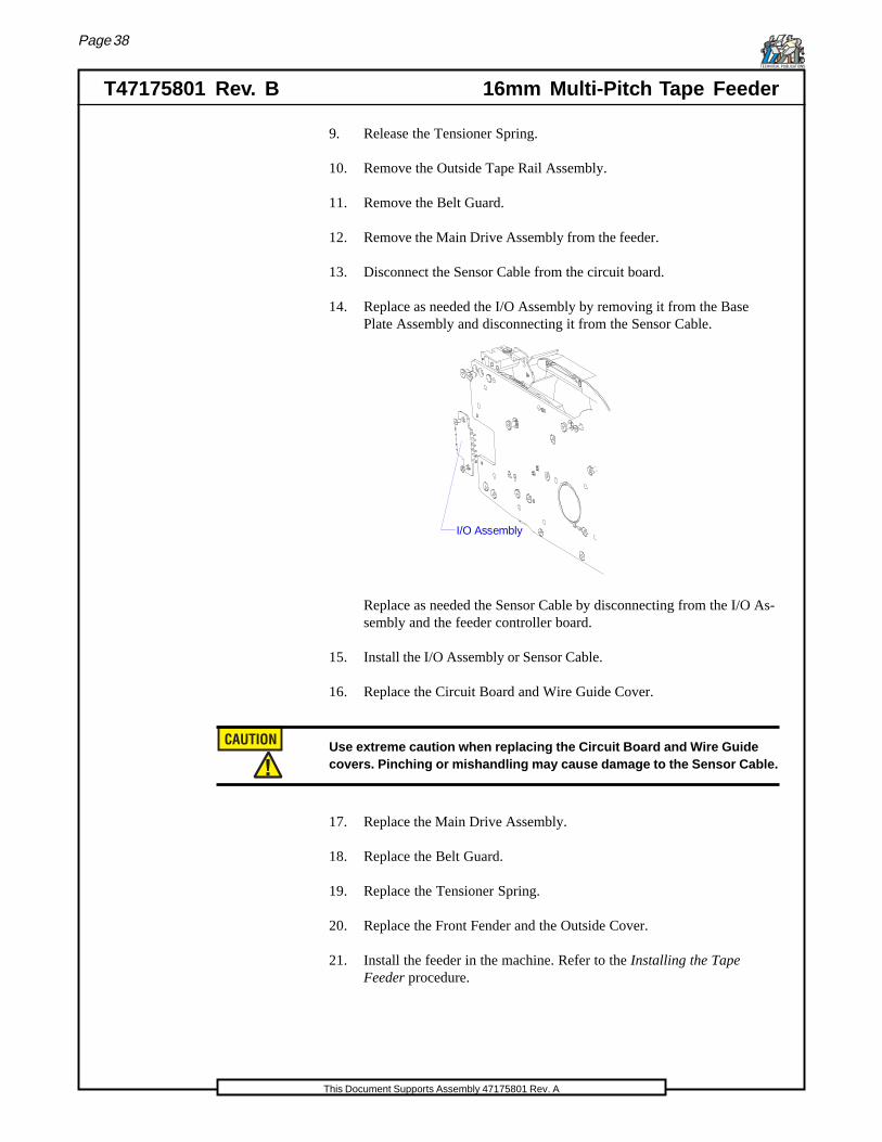
14. Replace as needed the I/O Assembly by removing it from the BasePlate Assembly and disconnecting it from the Sensor Cable.
I/O Assembly
Replace as needed the Sensor Cable by disconnecting from the I/O As-sembly and the feeder controller board.
15. Install the I/O Assembly or Sensor Cable.
16. Replace the Circuit Board and Wire Guide Cover.
Use extreme caution when replacing the Circuit Board and Wire Guidecovers. Pinching or mishandling may cause damage to the Sensor Cable.
17. Replace the Main Drive Assembly.
18. Replace the Belt Guard.
19. Replace the Tensioner Spring.
20. Replace the Front Fender and the Outside Cover.
21. Install the feeder in the machine. Refer to the Installing the TapeFeeder procedure.

Page 39
16mm Multi-Pitch Tape Feeder T47175801 Rev. BTECHNICAL PUBLICATIONS
This Document Supports Assembly 47175801 Rev. A
Replacing the Drive Belts
The Drive Belt and the Take-Up Wheel belt require periodic replacement.Replace these parts using the following procedure(s).
Use extreme caution when working around or handling either of the drivebelts, as they are delicate elements. These drive belts can be easilycrimped or bent. Mishandling causes damage to the belts and as a resultthey will need to be replaced.
Drive Belt Replacement
1. Remove six M2.5 screws to remove the Outside Cover.
2. Release the Tensioner Spring (as shown below.)
Gear CoverAssembly
TensionerSpring
3. Remove two M3 screws to remove the Outside Tape Rail Assembly.
Page 40
T47175801 Rev. B 16mm Multi-Pitch Tape FeederTECHNICAL PUBLICATIONS
This Document Supports Assembly 47175801 Rev. A
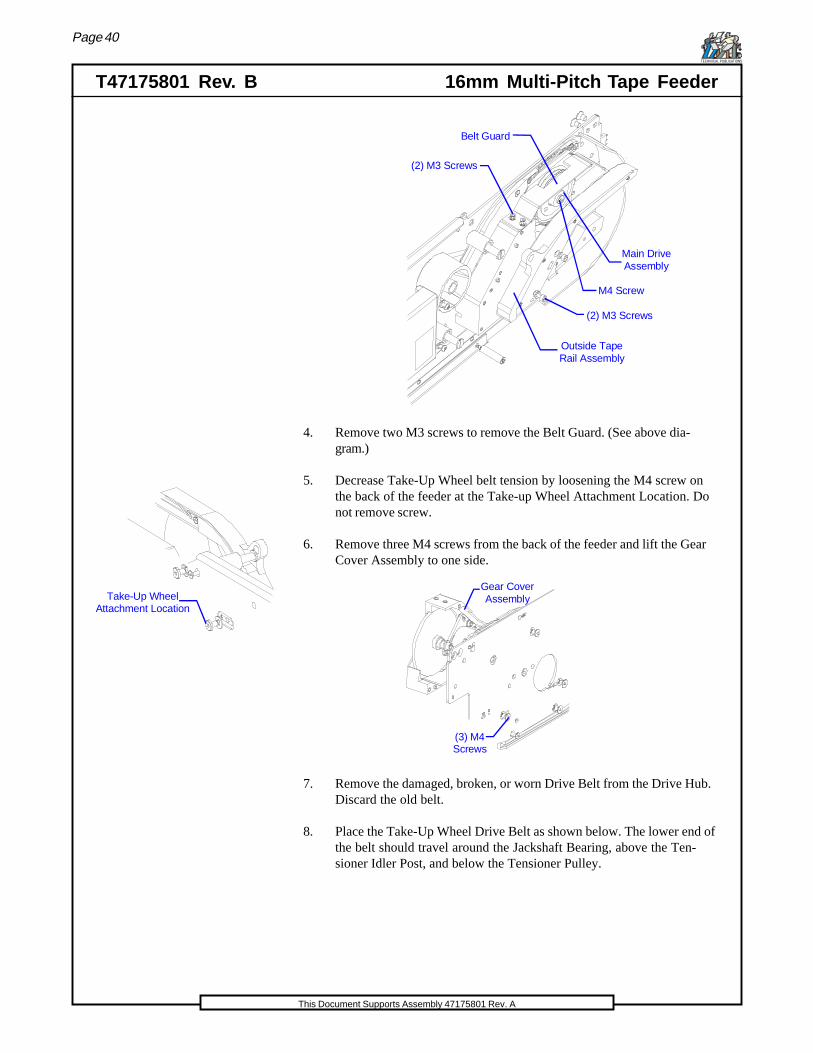
Outside Tape Rail Assembly
Belt Guard
Main DriveAssembly
(2) M3 Screws
M4 Screw
(2) M3 Screws
4. Remove two M3 screws to remove the Belt Guard. (See above dia-gram.)
5. Decrease Take-Up Wheel belt tension by loosening the M4 screw onthe back of the feeder at the Take-up Wheel Attachment Location. Donot remove screw.
Take-Up WheelAttachment Location
6. Remove three M4 screws from the back of the feeder and lift the GearCover Assembly to one side.
(3) M4Screws
Gear CoverAssembly
7. Remove the damaged, broken, or worn Drive Belt from the Drive Hub.Discard the old belt.
8. Place the Take-Up Wheel Drive Belt as shown below. The lower end ofthe belt should travel around the Jackshaft Bearing, above the Ten-sioner Idler Post, and below the Tensioner Pulley.

Page 41
16mm Multi-Pitch Tape Feeder T47175801 Rev. BTECHNICAL PUBLICATIONS
This Document Supports Assembly 47175801 Rev. A
9. Place the new Drive Belt as shown below. It should travel around theJackshaft Bearing and ride on the lower side of the Tensioner Pulley.
Drive Belt
Gear CoverAssembly
JackshaftBearing
Tensioner Pulley
TensionerIdle Post
Take-Up WheelDrive Belt
10. Replace the Gear Cover Assembly. Ensure that the Drive Belt and theTake-Up Wheel Drive Belt are seated around the Drive Hub.
11. Tighten the M4 screw on the back of the feeder at the Take-up WheelAttachment Location. Adjust the Take-Up Wheel tension. (Refer to theTake-Up Wheel Tensioning procedure earlier in this document.)
12. Reverse the above steps to reassemble the tape feeder.
Take-Up Wheel Belt Replacement
1. Remove six M2.5 screws to remove the Outside Cover.
2. Release the Tensioner Spring (as shown below.)
Gear CoverAssembly
TensionerSpring
3. Remove two M3 screws to remove the Outside Tape Rail Assembly.
Page 42
T47175801 Rev. B 16mm Multi-Pitch Tape FeederTECHNICAL PUBLICATIONS
This Document Supports Assembly 47175801 Rev. A
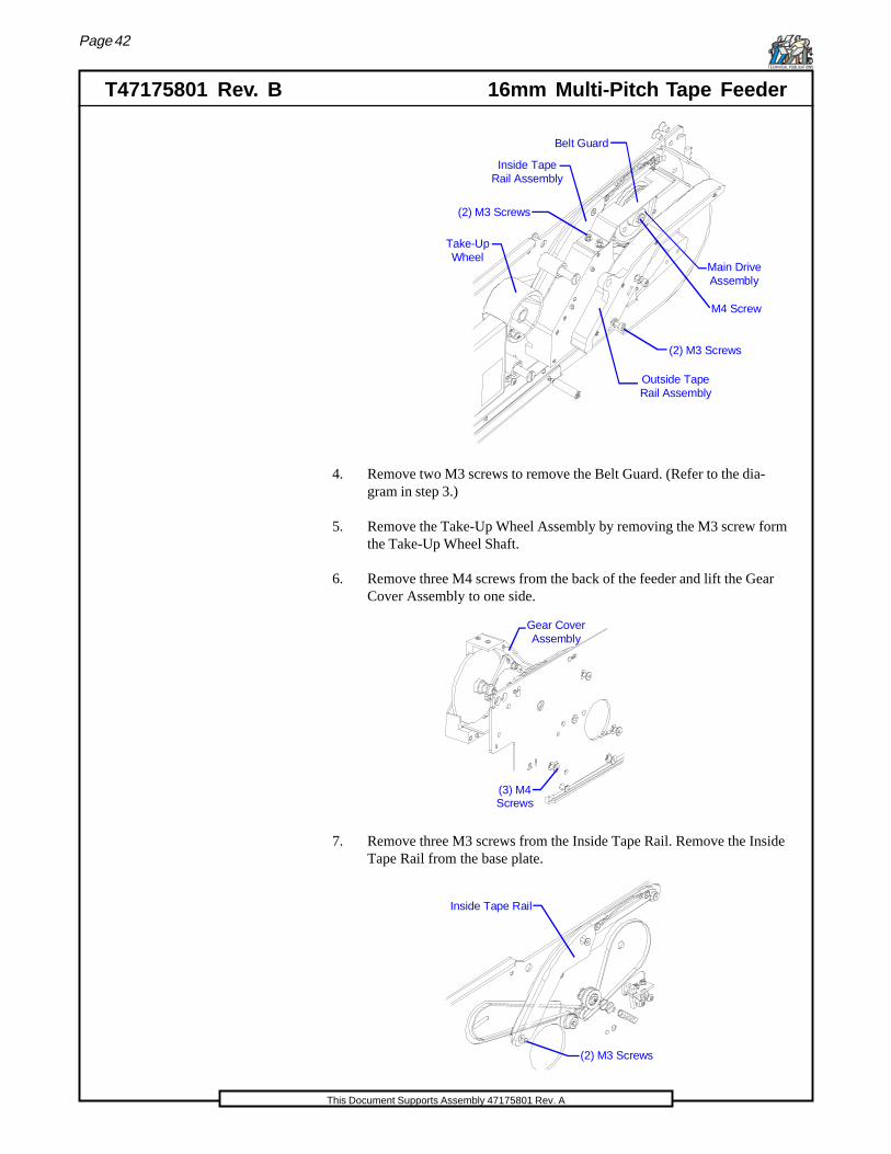
Outside Tape Rail Assembly
Belt Guard
Main DriveAssembly
(2) M3 Screws
(2) M3 Screws
M4 Screw
Take-UpWheel
Inside TapeRail Assembly
4. Remove two M3 screws to remove the Belt Guard. (Refer to the dia-gram in step 3.)
5. Remove the Take-Up Wheel Assembly by removing the M3 screw formthe Take-Up Wheel Shaft.
6. Remove three M4 screws from the back of the feeder and lift the GearCover Assembly to one side.
(3) M4Screws
Gear CoverAssembly
7. Remove three M3 screws from the Inside Tape Rail. Remove the InsideTape Rail from the base plate.
Inside Tape Rail
(2) M3 Screws

Page 43
16mm Multi-Pitch Tape Feeder T47175801 Rev. BTECHNICAL PUBLICATIONS
This Document Supports Assembly 47175801 Rev. A
8. Remove the Drive Belt from the Drive Hub. Remove the damaged, bro-ken, or worn Take-Up Wheel Drive Belt from the Drive Hub.
9. Place the new Take-Up Wheel Drive Belt as shown below. The lowerend of the belt should travel around the Jackshaft Bearing, above theTensioner Idler Post, and below the Tensioner Pulley.
10. Place the Drive Belt as shown below. It should travel around the Jack-shaft Bearing and ride on the lower side of the Tensioner Pulley.
Drive Belt
Gear CoverAssembly
JackshaftBearing
Tensioner Pulley
TensionerIdle Post
Take-Up WheelDrive Belt
11. Seat the Take-Up Wheel Drive Belt the Drive Hub first. Then ensurethat the Drive Belt is seated around the Drive Hub. Replace the GearCover Assembly.
12. Tighten the M4 screw on the back of the feeder at the Take-up WheelAttachment Location. Adjust the Take-Up Wheel tension. (Refer to theTake-Up Wheel Tensioning procedure earlier in this document.)
13. Reverse the above steps to reassemble the tape feeder.

Page 44
T47175801 Rev. B 16mm Multi-Pitch Tape FeederTECHNICAL PUBLICATIONS
This Document Supports Assembly 47175801 Rev. A
Always use the proper ESD (Electric Static Discharge) protectiondevices (wrist strap, cable, and static dissipative mat) and techniqueswhen handling electronic components such as the Motor ControllerBoard.
Motor Controller Board Replacement
Use the following procedure to replace the Motor Controller Board.
Use extreme caution when ordering motors for the tape feeders. Thereare two different 16-56mm Multi-Pitch Tape Feeder part number series.The 47178801 uses a 040A-S04 motor, and the 47178802 uses a 042A-S04 motor.The motors are not interchangeable.
Also, use extreme caution when working with the control boards becausethe part number ot the control board did not change. Do not remove anold control board (from a 47178801 feeder) and place it in the (47178802feeder), because the boards appear the same, but electronically are notinterchangeable. If this happens the board will be damaged. A controlboard from the 47178802 will work with either a 042A-S04 or a 040A-S04motor.
1. Remove six M3 screws to remove the Board Cover form the Baseplate.
(6) M3 Screws
Control PanelAssembly
Board StandoffStud (2)
Motor ControllerBoard
M3 Screw
(3) M3Screws
Board Cover
Baseplate
2. Remove two Board Standoff Studs and three M3 Screws from the Mo-tor Controller Board. Refer to the above diagram.

Page 45
16mm Multi-Pitch Tape Feeder T47175801 Rev. BTECHNICAL PUBLICATIONS
This Document Supports Assembly 47175801 Rev. A
3. Remove one M3 screw from the Control Panel Assembly. Remove theControl Panel Assembly. Refer to the above diagram.
4. Disconnect three wire assemblies from the Motor Controller Board andremove the board from the Baseplate.
5. Replace the new Motor Controller Board.
6. Reverse the above steps to reassemble the tape feeder.
7. Set the Factory Default Pick Point. (Refer to the Factory Default PickPoint Adjustment section earlier in this documentation.
Feeder Database
When operating 16mm Multi-Pitch Tape Feeders on Platform machines us-ing UPS software prior to UPS 3.0.1 it is necessary to load Feeder Databaseinformation using the Feeder Database Window.
When operating 16mm Multi-Pitch Tape Feeders on Platform machinesoperating on UPS 3.0.1 and higher, manual input of feeder databaseinformation is not necessary.
1. From the Feeder Database window, select Add from the Feeder menubar heading. The Select Feeder Type dialog box is displayed.
2. Select Tape from the Feeder Type list box and then the OK push but-ton. The New Feeder window is displayed.
Page 46
T47175801 Rev. B 16mm Multi-Pitch Tape FeederTECHNICAL PUBLICATIONS
This Document Supports Assembly 47175801 Rev. A
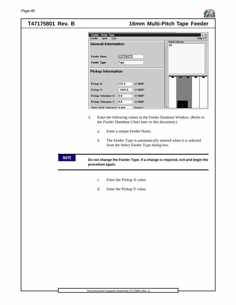
3. Enter the following values in the Feeder Database Window. (Refer tothe Feeder Database Chart later in this document.)
a. Enter a unique Feeder Name.
b. The Feeder Type is automatically entered when it is selectedfrom the Select Feeder Type dialog box.
Do not change the Feeder Type. If a change is required, exit and begin theprocedure again.
c. Enter the Pickup X value.
d. Enter the Pickup Y value.
Page 47
16mm Multi-Pitch Tape Feeder T47175801 Rev. BTECHNICAL PUBLICATIONS
This Document Supports Assembly 47175801 Rev. A
If the Feeder Teach procedure will be used, enter a value of 0.0 for thePickup X and Y values. Refer to the Feeder Teach procedure in theUser's Guide or in Platform Configurations/Options.
e. Enter the Pickup Tolerance X.
f. Enter the Pickup Tolerance Y.
g. Enter the Theta Pick Tolerance.
h. Enter the number of Pick Attempts.
i. Enter the Number of Slots the feeder occupies.
j. Enter the Width of the feeder. If the feeder is not used on a PPAmachine, enter 0.0.
k. Designate the Reference Slot.
l. Enter the necessary Extend Delay.
m. Enter the necessary Retract Delay.
n. Enter the necessary Double Stroke.
4. Select the Save option under the Feeder menu bar heading. The feederdefinition is saved to the current database.
Page 48
T47175801 Rev. B 16mm Multi-Pitch Tape FeederTECHNICAL PUBLICATIONS
This Document Supports Assembly 47175801 Rev. A
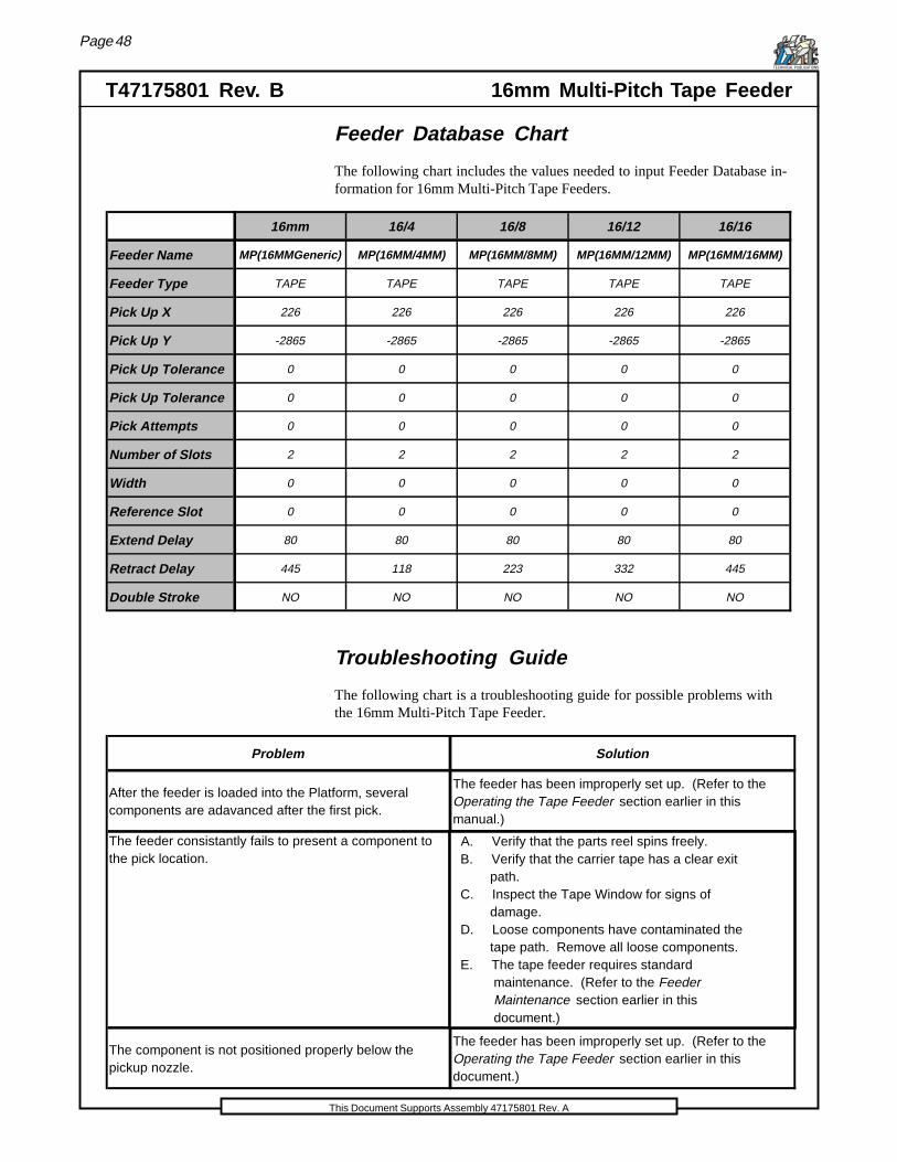
Feeder Database Chart
The following chart includes the values needed to input Feeder Database in-formation for 16mm Multi-Pitch Tape Feeders.
16mm 16/4 16/8 16/12 16/16
Feeder Name MP(16MMGeneric) MP(16MM/4MM) MP(16MM/8MM) MP(16MM/12MM) MP(16MM/16MM)
Feeder Type TAPE TAPE TAPE TAPE TAPE
Pick Up X 226 226 226 226 226
Pick Up Y -2865 -2865 -2865 -2865 -2865
Pick Up Tolerance 0 0 0 0 0
Pick Up Tolerance 0 0 0 0 0
Pick Attempts 0 0 0 0 0
Number of Slots 2 2 2 2 2
Width 0 0 0 0 0
Reference Slot 0 0 0 0 0
Extend Delay 80 80 80 80 80
Retract Delay 445 118 223 332 445
Double Stroke NO NO NO NO NO
Troubleshooting Guide
The following chart is a troubleshooting guide for possible problems withthe 16mm Multi-Pitch Tape Feeder.
Problem Solution
After the feeder is loaded into the Platform, several components are adavanced after the first pick.
The feeder has been improperly set up. (Refer to the Operating the Tape Feeder section earlier in this manual.)
The feeder consistantly fails to present a component to the pick location.
The component is not positioned properly below the pickup nozzle.
The feeder has been improperly set up. (Refer to the Operating the Tape Feeder section earlier in this document.)
A. Verify that the parts reel spins freely. B. Verify that the carrier tape has a clear exit path. C. Inspect the Tape Window for signs of damage. D. Loose components have contaminated the tape path. Remove all loose components. E. The tape feeder requires standard maintenance. (Refer to the Feeder Maintenance section earlier in this document.)
Page 49
16mm Multi-Pitch Tape Feeder T47175801 Rev. BTECHNICAL PUBLICATIONS
This Document Supports Assembly 47175801 Rev. A
Changes To This Revision
Added caution to pages 19 and 44.
i
16mm Multi-Pitch Tape Feeder T47175801 Rev. BTECHNICAL PUBLICATIONS
This Document Supports Assembly 47175801 Rev. A
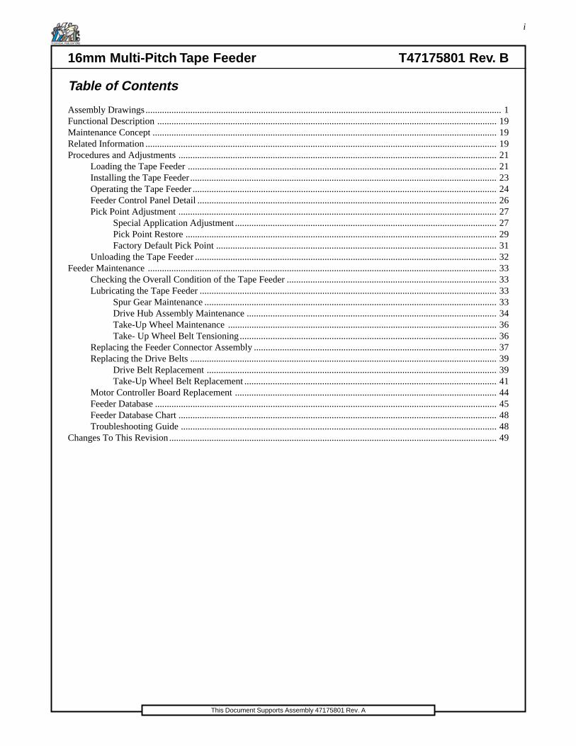
Table of Contents
Assembly Drawings....................................................................................................................................................... 1Functional Description ................................................................................................................................................ 19Maintenance Concept .................................................................................................................................................. 19Related Information ..................................................................................................................................................... 19Procedures and Adjustments ....................................................................................................................................... 21
Loading the Tape Feeder ................................................................................................................................... 21Installing the Tape Feeder.................................................................................................................................. 23Operating the Tape Feeder ................................................................................................................................. 24Feeder Control Panel Detail ............................................................................................................................... 26Pick Point Adjustment ....................................................................................................................................... 27
Special Application Adjustment ............................................................................................................... 27Pick Point Restore .................................................................................................................................... 29Factory Default Pick Point ....................................................................................................................... 31
Unloading the Tape Feeder ................................................................................................................................ 32Feeder Maintenance .................................................................................................................................................... 33
Checking the Overall Condition of the Tape Feeder ......................................................................................... 33Lubricating the Tape Feeder .............................................................................................................................. 33
Spur Gear Maintenance ............................................................................................................................ 33Drive Hub Assembly Maintenance .......................................................................................................... 34Take-Up Wheel Maintenance .................................................................................................................. 36Take- Up Wheel Belt Tensioning............................................................................................................. 36
Replacing the Feeder Connector Assembly ....................................................................................................... 37Replacing the Drive Belts .................................................................................................................................. 39
Drive Belt Replacement ........................................................................................................................... 39Take-Up Wheel Belt Replacement ........................................................................................................... 41
Motor Controller Board Replacement ............................................................................................................... 44Feeder Database ................................................................................................................................................. 45Feeder Database Chart ....................................................................................................................................... 48Troubleshooting Guide ...................................................................................................................................... 48
Changes To This Revision........................................................................................................................................... 49
16mm
Multi-Pitch TapeFeeder
16mm
Multi-Pitch TapeFeeder
16mm
Multi-Pitch TapeFeeder
16mm
Multi-Pitch TapeFeeder
16mm
Multi-Pitch TapeFeeder
4697A 16mmMulti-Pitch TapeFeeder
T47175801Rev. B04-99mds,dt,adThis document supportsassembly47175801 Rev. A