technica of screenin guides
TRANSCRIPT

SPE-~~ ‘~tiAIME
SPE 12069
T&clrical Screening Guides for the Enhanced Recovery
by J,J. Taber and F.D. Martin, New Mexico /nst. of MhhIg & 7’echno/ogy
Members SPE.AIME. . ..- ---- . .—
Copyright 1983 Society of Petroleum Englneere of AlME
TFJspepar was presenled a! the 58th Annual Technical Conference and Exhibition held In Sen Francisco, CA, October 5-8,1983. The material Is subjeotto correction by the author. Permission to copy is restricted 10 an ebslract of not more Ihan 300 words. Wrile SPE, $200 North Cenlral Expressway,Drawer 64706, Dallas, Tsxaa 75206 USA. Telex 730989 SPEOAL,
ABSTRACT methode. The NPCreport will continue to be theauthority on technical screening criteria,
The technical ecreening guidee which are ueed especially when th new adition ie publiehed withinto select enhanced oil recovery methods are the next year. 5 Other guidelines have beandeecribad. The background and logic behind the auggeetedvarloue criteria are covered, and a brief enhanced ‘or ‘he appli~:f~:ndOffo:;~d:;description of each method is included. Econaaice ProCeeeae,f%~9~ery metkd~are diecuaeed, but the emphaaie la on the technicalguideline. Meet cempaniee have their own technical
screening criteria for enhanced recovery. TheA distinction ie made batween the oil canpany guidelines are often a combination of the
propertied aml reeervoir characteristic required NPC valuee and peremetere which have bean adjuetedfor each proceea. Oanerally, eteamflooding ie to include the lateat data from the laboratory andapplicable for viecoue oile in relatively shallow field. After the technical ecreenin8 guidee haveformations, At the other extreme, C02, nitrogen, been applied to a given proepect, the moreand hydrocarbon miscible flooding work beet with stringent economic ecreening proceae muet takevery light Oils at depths great enough for place before the final dacieion ie made,miscibility to be achieved. Both steantflooding and Experienced engineers mey be adept at utilizingin-situ canbuetion require reeervoire of fairly both kinds of screening guidee; however, newerhigh permeability. Chemical flooding proceseee(polymer,
engineere often need a eyetematic presentation ofalkaline or aurfactant) are applf.cable the technical screening criteria. Thie paper is
for low-to-medium viecoeity oils where depth ie not our a:teupt to fulfill this need and provide thea major conelderation. However, at great depthe, reaeone for the epecific parameter which arethe higher temperature may preeent problems In the listed.da8radation or consumption of some of thechemicale. Our approach ie to present the technical
ecreening criteria in tables and graphe along withCurrent valuea of the technical ecreaning diecueeion of the principles or benic recovery
guidee for the more cmnmon enhanced recovery mechanieme which limit the technical eucceae ofprocedures are given in tabular and graphical form. eech ❑ethod. We draw a distinction between theBy the use of a eimple graphical technique, it ie criteria which are related to oil propertied and toshown that there Ie a complete apactrum of enhanced thoee which depend on reeervoir characterietice.011 recovery methode a~ailable for all oile, In the literature, the deeired oil or reservoirranging from the very lightest to the heavieet oil valuee are usually given aa either an uppar oror tar aand. lower limit for each characteristic, Howavar,
INTRODUCTIONtheee valuee are not absolute; a number of fieldprojecte are underway with oil or rocke which areouteide the published limite, Therefore, to @Ve a
Screening guidee or criteria are among the more realietic picture, wa have developed graphefirst itame considered when e petroleum engineer which chow a deeirad range of valuea for some ofevaluatee a candidate reeetwoir for enhanced oil the more Imwrtant characteriatica euch ae oilrecovery (EOR). The source most oftan quoted for viecoelty, The fig*lree chow that there ie ascreening criteria ia the 1976 National Pe roieum
ivariety of et, anced recovery methode available for
Council (NPC) report on Enhanced Recovery, which all oile, from the vary lighteet to the heavieetliete the criteria for eix enhanced recovery oil or tar eand,
Reference and illuetratione at end of paper.

RATIONALEFORUSINGSCREENINGGUIDES
Implementation of enhanced recovery projecteis expenelve$ time-coneuming, and people-intenelve.Substantial coets are often involved in theaesesement of reservoir quality, the amount of oilthat is potentially recoverable, laboratory workaaeociated with the EOR process, ccrnputereimulatione . recovery, andperformance of % p~o$~~ Oneof the ftret et~~in deciding to consider EOR ie, of courea, toselect reeervoira with efficient recoverable oiland areal extent to make the venture profitable.
With aryy of tha proceesea, the natura of there8arvoir will play a dominant role in the eucceeeor failure of the proceee. Many of the failureewith EOR have reeulted because of unknown orunexpected reservoir problems. The, a thoroughgeological etudy ie ueuzlly warranted.
27 and Farouq Ali21While we agrea with Pratethat each reeervoir must be evaluated individually,we feel the technique of using cursory screeningguides ie convenient for gaining a quick overviewof all poaeible methods before eelecting the beetone for an econanic analyeia. Commonsense andcaution must be exercised since the technicalguidee are based on laboratory data and reaulte ofenhanced recovery field triale, and are not rigidguides for applying certain proceesee to apeciftcreservoir. Additionally, tha technical merite ofrecent field projects are clouded by varioueincentive programe that make It difficult todiscern true tachnical applications. Some projectsmay have been technical misapplication orfalluree, but econmic aucceseee. Certainly, therehave been enough technical euccessee, but economicfailures.
Nevertheless, some EOR proceesee can berejected quickly becau8e of unfavorable reservoiror oil properties, ao the usa of preferred criteriacan be helpful in eelecting methode that may becazmercially attractive. If the criteria are toorestrictive, come feasible method may be rejactedfrom consideration. Therefore, the guidelines thatare adopted should be aufficie~tly broad toencamb.;ea essentially all of the potential methodsfor & candidate reeervoir. The best methode canthen be arrivad at in later evaluations, Thetechnical guidelines presented in thie paperrepresent a conseneus of many of the experte inthis field. Econmnics of the proceeses will bediecueeed later in the paper,
CLASSIFICATIONOF ENHANCEDRECOVERYMETHODS
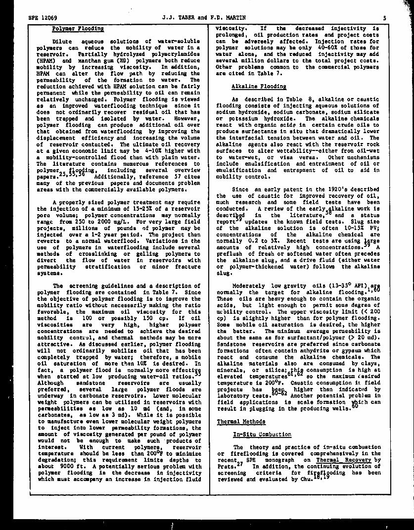
Before turning to the detailed screening@ales, it may be useful to Clat!sify the manyenhanced recwery methods which have been discussedin the literature and tried in the field. Fig. 1is a general schematic of enhanced recovery, and itcan apply to either tertiary or enhanced oecotiaryprojectam The special enhanced recovery fluid canbe any substance that doee a better job ofrecovering oil than plain water or gae. Thequantity of injected fluid can range from a smallfraction of th? reeervoir pore volume to more thanthe total x+re volume of the reserwoir. Obviouelv.
i *
if the ❑a~erial ie expensive, only a small amou;~can be used, ad it must be very effective in terms
of additional barrele of oil produced per barrlti~substance injected. If large volumee are required,the replacement fluids must be limited co water urone of tha inexpensive @SeSi.
On the other hand, the choice of materiala forenhanced recovery is very wide, and an enormouenumber of things have been tried in the laboratoryand pumped into the ground in the fond hope ofrecovering more oil. Table 1 liste eighteenenhanced recovery methods which have beenthoroughly teeted in the laboratory or the field,The uee of microbee for enhanced recovery is notincluded because of the lack of documented fieldtrials or conclusive laboratory teets. AlthoughTable 1 liete many choices, all of the methods canbe grouped into proceeses that involve either theinjection of water, gas or heat; or as a lastresort, the mining of the rock to recover the oil.
For eorting out the ecreeniog criteria, it isalso ueeful to claeeify the mettmds according tothe recovary mechanism. Table 2 shows that thereare really just three basic mechanism forrecovarlng oil from the rock more effectively thanby water alone. The methode are grouped accordingto tlwee which rely on a reduction of thaInterracial tension betwaen oil and water, theextraction of the oil with a solvent, the reductionof oil Viecoaity, or an increaae in waterviacoaity. In practice, of course, both heat andprl~esure in the thermal methode are needed for theproduction of viscous oile which could not beproduced by any othar method,
In a later section, it will bs shown thatviacoaity providee a good way to classify thamethods in a eequence from thoee which work beat onli8ht (CO!less viscous) Oils up thrOUBh those whichare needed for the heavy (or very VISCOUS)oile oreven tar sande. Since oil viscosity affectsrecovery much more than doee the oil gravity, weuae vfacoeity aa our primary reference in listingall of the methods, However” the API gravity iereported more ccromonly than the viscosity, andpublished ecreentng criteria often emphaeize thegravity requirement for enhanced recovery. Fig. 2shows a very general correlation by Beal 28 whichcan be used to provide a rough eetimate of gravityor viscosity if only one la known, The actual oilviaco8ity in the reseawoir ia normally eomewhatlower than that in Fig, 2 because of diesolvedBasea, and the temperatures may differsignificantly from the 100°F shown,
In the followi~ section, we present ecreening@deS for the eight catmon methods in Tables 3-11and for ten possible methods in Fig. 3, Themethods are arra~ed accordi~ to the viecosity ofthe oil to be recovered, Enhanced recovery canthen be classified ae three Bas injection mathoda,threa water related proceaees, three thermaltechniques, and mining and extraction when all elsefails.
GUIDELINESFORXAJORMETHODS
For cg.:”enience, a thumbnail sketch la givenfor the eight most cmamonenhanced recovery methodsin Tables 3-10 which list the ealient featuree ofeach ❑sthod along with the important screeningguides. A few general comments are offered here on

Dl? 191MQ J.J. TABERand F.D. MARTIN 3.- .--”.
the rcletive Importance of some individual ~?itrogen ~nd Flue Gae Floodlnqscreening guidee to the overall succees of thevarioua methods. In addition, we will make some AZ mentioned above, nitrogen and flue gaeobmervatlona on the method itself and its (about 87% N2 and 12% co~) ;re being usedrelationship to other anhancad recovery ckofces inczeaeingly in place of hydrocarbon gases becausewhich may be available. of econtmice. FtLtrogan alao caapates with C02 in
zome dtuationa for the sama reaaon. The economicBorne re8ervoir conaiderationa apply to all appeal of nitrogen atema not only from ite lower
enhanced recovery methode. Because drilling costa coat on a standard Mcf ba8iEP but also becauae itsincreaae markedly with depth, shallow resemoirs capraeaibility is much lower. Thus, for a givenare preferred, as long ae a:l nece8t3ary criteria quantity at standard condittona, nitrogan willare met. For the moat part, Reservoirs that have occupy much more apace at reservoir preeauresextensive fracturea, groea heterogeneities, thief C02 or aven methane at the came condition. 3$37
zones, or are highly faulted 8hould be avoided. However, both nitrogen or flue gas are inferior toIdeally, relatively uniform reaerwirs WIth hydrocarbon gaaea (and much inferior to C02) fromreasonable 011 eaturatione, ❑inimum ehale an oil recovary point of view. Nitrogen has aetringera, and good areal axtent are desired, lower vlaco8ity, poor volubility in oil and
requires a much higher pra88ura to generate orGas Injaction Methoda develop miscibility. The increaae in the required
preaaure ia significant compared to methane andHydrocarbon Miecible Floodin& very large (4-5 times) when compared to CO 9
Therefore, nitrogen will not ireduce t aCae injection Is cartainly oneof the oldest dieplacament efficiency too much when used a8 a
methods utilized by engineers to improve recovery, chase gas for methane, but it can cau8e aand ita uae haa increased recently, although moat significant drop in the effectiveneaa of a C02
~&r&ro~~bo~~~~p3 ‘~~ca~~o~?&in~=s~~flood if the reaewoir preaaurea ara geared to themiscibility requiramente for CO dieplacaments.
interest in C02 and nitrogen or flue ga8 methods, iIndeed, even methane counts ae a eairable “ i htwe have eeparated them from the hydrocarbon end” or “intermediate” in nitrogan flooding, 3+ :Utmiscible techniques even though other screening methana ie quite deleterious to tha achievement ofguides often lump them together as “Miscible Gas” miscibility in C02 flooding at modeet preesuras.projacte.
Aa shown in Table 4, the screening criteria’Hydrocarbon mlacible flooding can be for flooding with nitrogen or flus gas are similar
cub-divided further into three distinct methods, to those for the high pressure gaa drive. Presauraand field trials or extensi lt$’=r;:yn:~;po; and depth requirements, ae well as tha need for aconducted in all of them. very light oil , are evan greater if fullsolvent flooding, enriched (comlenaing) gae driva miscibility ie to be realized in the reaewoir.and high pressure (vaporizing) gas drive, a ra%e The nitrogen and flue gaa method la placed betweenof pressures (and tharefore, depths) are needed to hydrocarbon miacible and C02 flooding in the tablesachieve miscibility in the ayetema. Thus, thera is and in Fige. 3-5 becauae the proceaa can alsoa minimum depth requirement for each of the recover oil in. the immiscible mode. It can beprocasses aa shown in Table 3. The permeability is economic becauae much of the reeervoir epace ianot critical if tha structure ia relatively filled with lowcoet gae.uniform; permeabilitiee of the reaervoira for the
~!i$nt ~ldt$O~::& ‘a~d:wt$1:~5’~Carbon Dioxide FloodIn&
characteriatica are very important. A The thumbnail sketchhil@_graVity, low-viacoaity
of carbon dioxideoil with a high flooding Siven in Table 5 ehowa that C02 is
percentage of the C2 - C7 intermediates ie effective for recovery of oil for a number ofeeaential if miscibility 18 to be achteved in the reaaona, In Seneral, carbon dioxide is veryvaporizing gaa drivas. soluble in crude oils at reservoir pre88uree;
tharefore, it swells tha net volume of oil andUnleae the raaervoir characteriatica were reduces its viacoaity even before miscibility is
favorable, early breakthrough and bypaasing oflarge quantitifield prOjecta,f9B38f011‘at’e pla8ued many of ch,?
achieved by the vaporizing Sas drive mechaniem, Aamiscibility is approached, both the oil phase and
In addition, the hydrocarbon the CO phase (which contaiue many of the oil’eneeded for the proceseee are valuable, and there ie iinterme late ccqments) can flow together becauseincreasing reluctance to inject them back into tha of the low interracial tension and the relativeSround when there la some question about the increaee in the total volumes of the combined C02pe:eentage that till be racoverad the eecond time and oil phasea compared to the water phase,around. Therefore, in recent yeara the emphaB18 However, the Saneration of miscibility between thehas teen ehifting to less valuable non-hydrocarbon oil and CO la still the ❑eet important mechanism,SaseeA~th0u8h%L& 21’ fRt~& d%O;tiO#%i
ia@ it @l occur in C02-cruda oil ayatama ae 10II8aa the pressure ia high 0nOUJ4ht This so-called
ae well ae the hydrocarbon sasee (or liquide), the “minimum m18clbility pressure” or MMPhas been theoverall econmuics may be somewhat more favorable. targat of several laboratory investisatiouA Sood example of a direct switch ie the ongoing no longer a uyztery.recovery project in University Block 31, CraneCounty, Texae.
The 1976 NPCreport! :~w~~that there ia a rOUgh correlation between the API
Thie high preaaure gas drive which gravity and the required MMP,and thet the MMPetarted ❑ore than 30 yeare ago wae changed to flue increased with temperature, Varioua workere havasas i~~e$~i$g in 1966 and la atill going strongtoday. s $

4 TECNNKALSCREENINGGUIDESFORTNEENNANCEDRECOVERYOF OIL SPE 12069
.ndarata*iq)6tig’tiOna ‘“” ad ~provad O. C,=
presented muc since mobilized oil might re-saturate the gas cap.Some have shown that a better Fomatione with high clay contanta ara undesirable
correlation 18 obtained with the molecular weight eince the clays increaze adsorption of the in$ected+ fractionof the oil than with the APIof the C5 chemicalo. In most cases, reservoir brinee of
gravity. In general, the recent work ohowz that moderate ealinity with low amounts of divalent ionsthe required pressure met
be ‘@h ‘n0u8!8,t8are preferred since high concentrationzi interact
achieve a minlrzum density In the C02 phase, unfavorably with the chemicals that are injected.At this minfmwmdeneity, which varies with the oil Specific ecraening @idelines are discussed forcomposition, the C02 bacmzes a good solvent for the each of tha chemical ❑ethods that follow.oil, especially the tntarmzdiate hydrocarbons, andthe required miscibility can ba generated or Surfactant/Polymer Floodingdeveloped to provide the efftciant displacementnoamelly observed with C02* Therefore, at higher Surfactant uee for oil recovery is not atemperatures, the higher pressuraa are needed only recent development, Patenta in the late 1920’s andto increase the C02 deneity to the asme value as early 1930’e propmad the use of low concantrationaobserved for the MMPat the lower temperature, of detergents to reduce the Interracial tension
between water and oil, To overtBecause of the minimum pressure requiramant, %? ::P::: ;:;;of advance of tha datergent, Taber
depth is an im~rtant screening criteria, and C02 high concentrations (.1OZ) of detergent in aqueousfloods are normally carried out in reaervoir8 that aolutiongare more than 2000 ft deep. The oil composition isalso tmportant, and the API gravity
3Yceeds 30° for Duri~ the late 19501s and early 1960~e,
moat of tha active C132floods. A notable eeveral diffarent present-day methode of usingexception is t~ll Lick Creek, Arkansaa, surfactants for enhanced recovery were developed.C02/waterflood projadt which is bei~ conducted A review of these methods is E:lorui the sco
immiscible dis&~:~~h=ible ‘r”’ect’ but as an ‘his ‘Wr an’ ‘successfully, !K,jt.s ~~a~~a-oie an the literature.
In come systems, a small slug (> about 5%PV) wasproposed that included a high concentratlonof
Although the mechanism for (X)2 flooding eurfactant (noxmally 5-1OZ). In many cases, theappears to be the same as that for hydrocarbon microsmulsion includes surfactant, hydrocarbon,mizcible floods , C02 floods may give batter water, an electrolyte (salt), and a cosolventrecoveries even if both systems arc abova their (usually an alcohol). Thesa methods ordinarilyrequired miecibiltty pressures, especially in used a SIUS (30-50% PV) of polymar-thickenad watartertiary floods. Compared to hydrocarbons, C02 has to provide mobility control in displacing thea much higher volubility in water, and It has baen surfactant and oil-water bank to the producingobaervad in laboratory experiments to diffuse Wellso The polymers used are tha same as thosethrough the water ph e to swell bypassed oil untilthe oil ismobile~~
discussed in the n~t eection of tha paper. InThus, not only are tha oil meet cases, low-coat petroleum eulfonates or blends
and dapth screening criteria easier to meat in C02 W1th other surfactants have bean used.floodin&, but the ultimate recovery may ba better Intermediate surfactant colicentrations and lowthan with hydrocarbons when abova the MMP, It must concentration systems (low tension waterflooding)be noted, however, that this conjecture has not have also been proposed. The lower surfactantbeen proved by rigoroue and directly ccmpzrable concentration eyetama may or may not containexperlmante. polymer in the eurfactant slug, but wI1l util$ze a
larger elug (3O-1OCMPV) of polymer solution,Chemical Flcoding Methods
A brief description of the surfactanttpolymerChemical oil recovery methode Includa polymer, method is provided in Table 6. Oil viscosities of
surfactant/pol~er (variation are called less than 30 cp are desired so that adequatemicellar-polymer, microemulsion, or low tension mobility control can be achieved. Cood mobilitywaterflooding), and alkaline (or caustic) floodlng. control is essential for this method to mekeAU of these methods involve mixing chemicals (and maximum utilization of the expensive chemicals.sometimes other eubsts.nces) in water prior to Oil eaturationa remaining after a waterflood shouldin~ectiona Therefore, these methods require be more than 30% PV to ensure that sufficient oilconditions that are very favorable for water is available for recovery, Sandstor.ea areinjection: low-to-moderate oil viecositiee, ami praferred becauae carbonate reservoirs aremoderate-to-high parmaabilitiae, Hence, c+emical heterogeneous, contain brines with high divalentflooding is used for oils that are more viscous ion contents, and cause high Sd60rptiOn of Cmumonl.ythan those oils recovered by gae Injection methods, used surfactants. To ensure adequate injectivity,but less viscous than oile that can be econaicelly permeability nhould be greater than 20 md.recwerad by themal methds. Reservoir Resarvoir temperature should ba less than 175°F toparmeabilitiee for chemical flood coti?,tions need minimize degradation of the presently availableto be highar than for the gas ~njection methods, surfactanto. A number of other limitations andbut not &a high as for thermal mettmds. Sincelower mobility fluids are usually injacted in
problems are mentioned in Table 6, includi~ theganerel requirement for low ealinity and hardness
chemicaL floods, adaquate injectivity is rquired. for most of the camercially availabla aysteme.If previously wnterflooded, tha chemical flood Obviously, this method is very caeplex, expenatve,candidate Shoulc havo responded favorably by and subjact to a tide ra~e of problems, Meetdevalopi~ ●n oil bank. Generally, active importantly, the available ayatems provide optimumwater-drive resarvoira should be avoided because of reduction in interracial teneion over a vary narrowthe potential for low remaining oil saturations, salinity ranseo Prefluehee have bean used toRe8ervoira with gas caps ●re ordtnarly avoidad attampt to provide optimum conditions~ but they
have often been ineffective.
SPE 12069 J.J. TASERand F.D. MARTIN 5
Polymer Floodin~ Viecoeity, If the decreeeed in~ectivity ieprolonged, oil production rates and project coets
Dilute aquaoue aolutiona of water-eoluble can be advereely affected. Injection ratea forpolymere can reduca the mobility of water in a polymer eolutions may be only 40-60% of ttmee forreeervoir. Partially hydrolyzed polyacrylamidee(HPAH) and xanthangum(XG) polymere both raduce
water alone, and the reduced in~ectivity may addeevaral million dollare to the total project costa.
mobility by increasing viacoaity, In addition, Other probleme commonto the commercial polymersHPAM can alter the flow path by reducing the are cited in Table 7.permeability of the formation to water, Thereduction achieved with HPAMeolution can be fairly Alkaline Floodingpermanent while the permeability to oil can remainrelatively uncha~ed. Polymer flooding ie viewed Ae described in Table 8, alkaline or causticae an improved waterflooding technique eince it flooding coneiete of injecting aqueoue solutions ofdoea not ordinarily recover residual oil that haa sodium hydroxide, sodium carbonate, sodium silicatebeen trappad and isolated by water. Howevar, or potaeaium hydroxide. The alkaline chemicalepolymer floodi~ can produce additional oil over react with organic acidg in certain crude oils tothat obtained from waterflooding by improving the produce eurfactante in situ that dramatically lowardisplacement efficiency and increasing the volume the interracial tension between wate: and oil* Theof reservoir contacted. The ultimate oil recovery alkaline agents also react with the reservoir rockat a given economic limit may be 4-1OZ hi8her with eurfaces to alter nettability--either from oil-wata mobility-controlled flood than with plain water, to water-wet, or vies versa. Other machaniamaThe literature contains numerous references to include emulsification and entrainment of oil or
‘1per25,!*:s$iW~ddi~$~~: re~~~;ti T:::emulsification and entrapment of oil to aid in
papare. mobility control,many of the prwious papara and documents problemareas with tha canmercially available polymare. Since an aarly patent in the 1920’e deacrib~
the uee of cauatlc for improved recovery of oil,Aproparly sized polymer treatment may require much raaearch and some field teete have been
the injection of aminlmum of 15-25% of a reservoir conducted, A review of the early lkaline work iepore volume; polymer concentrations may normallyrange from 250 to 2000 mg,fL. For very large field ~:::!!$updflee ‘he literatureS$ ad a statusthe known field teste. Slug sizeprojecte, millions of pounds of polymer may be of the alkaline solution ia often 10-15Z PV;injected over a 1-2 year peliod* The project then concentration of the alkaline chemical areraverte to a normal waterflood, Variation in the normally 0.2 to 5X, Recent teste are using ~~r8euee of polymere in waterflooding include several amounta of relatively high concentration* Amethode of croaelinking or gelling polymers to prefluah of freeh or eoftened water often precadeadivert the flow of water in reaervoire with the alkallne elug, and a drive fluid (either waterpermeability stratification or minor fracture or polymer-thickanad water) follows the alkalineeyatema. slug 9
The ecreening guideline and adeacriptionof Moderately low gravity oils (13-35° API) apolymer flooding are contained in Table 7. Since 1 8%normally the target for alkaline flooding. Dthe objactive of polymer flooding ie to improve the These oils are heavy enough to contain the organicmobility ratio without neceeearily making the ratio acida, but light enough to permit some degree offavorable, the maximum oil viacoafty for this mcbility control. The uppar viacoaity limit (<200method is 100 or poeeibly 150 cp. If oil cp) ia slightly higher than for polymer flooding,vfecoeitiea are very high, hisher polymer Some mobile oil saturation ie desired, the higherconcentration are needed to achiava the deairad the better. The minimum average permeability iemobility contual, and thermal methods may be mora about the same as for eurfactant/polymer (> 20 red).attractive. Aa diecuesed earlier, polymer flooding Sandstone reservoirs are preferred since carbonatewill not ordinarily mobilize oil that hae been formation often contain anhydrite or gypaum whichcompletely trapped by water; therefore, a mobile react and consume the alkaline chemicals. Theoil maturation of more thm 10X is deeirad. In alkaline materiale alao are consumad by claya,fact, a polymer flood ie noncally more effacti
Nminerala,
when started at low producing water-oil ratioa, elevated t&a;~;$~;6t~4f ;;n;~pt~i;; )X;Although eandetone reeervoire are usually temperature Is 200°F. Cauetic consumption II fieldpreferred, several Iatge polymer floode are
laboratory !~~ta]&$t2 ~~~~ ~~t#~~&o ~projecte
underway in carbonate reeemoire* Lower molecularwalght polymers can be utilized in reeervoire with field application ie scale formation &tc.h canpermeabilitiea ae low aa 10 ❑d (and, in acme result in plugging in the producing wells*carbonate, ae low aa 3 red), While it ie poesibleto manufacture even lower molecular weight polymers Thermal Methodgto inject into lower ~rmeability formation, theamount of viecoeity generated par pound of polymer In-Situ Combustionwould not be enOu8h to make such ‘products ofinterest. With current polymers, resarvoir The theory and practice of in-situ ccmbuetiontemperature should be lees than 200°F to minimize or fireflooding ie covered canprehensivaly in thedegradation; this requirement limtta deptha to recent monograph on Thermal Recovery byabout 9000 ft. A ~tentially serloua problem with Prata.27 ‘P;n addition, the continuing evolution ofpolymer floodi~ la the decreaee in injectivity screening critariawhich must acc~~ny an increaee in injection fluid ‘or ‘ifgfigodi~ ‘aa beenreviewed and evaluated by Chug

6 TECHNICALSCREENINGGUIDES FOR THE ENHANCEDRECOVERYOF OIL SPE 12069
Part of the appeal of ffreflooding caues from The eteam drive may work bydrfviog the waterthe fact that it uses the world’s cheapest and most and oil to form an oil bank ahead of the steamedplentiful fluids for injection: air and water. zone. Ideally thie oil bank remains in front,However, significant amounts of fuel must be increasing in size until It is produced by theburned, both above the Bround to compress the air, wells offeettl~ the injector. However, in manyand below ground in the combustion process. caaes, the steam flows over the oil and transfersFortunatl?ly, the worst part of the crude oil is heat to the oil by conduction. Oil at theburned; the lighter ends are carried forward in interface is Lowered in viscosity and dragged aloadvance of the burning zone to upgrade tho crude With the steam to the producing wells. 8
oil* Recoverability is increased because the steam(heat) lowers the oil viscosity and improves oil
For ecreening purposes (see Table 9), mobility. Ae the more mobile oil is displaced, thesteamflooding and Fireflooding are often considered steam zone expands vertically, and the steam-oiltogether. In general, combustion should be the interface is maintained. This process ischoice when heat Losses from steamfloofling would be energy-inteneive since it requires the use of atoo great. In other words, combustion can be significant fraction (25-40%) of the energy in thecarried out in deeper reservoirs and thinner, produced petroleum for the generation of steam.tighter sand eections where heat losses forsteemflooding are excessive. The ability to inject Screening criteria for steamflooding areat high pressures is usually important so 500 ft Listed in Table LO. Although steamflooding iahas been retained as the minimum depth, but we note commonly used with oils ranging in gravity fromthat there are three curren projecte underway at
5310-25° API, some gravities have been lower, and
depths of less than 500 ft. There appears to be~~~~Zv~~r~~$f~~4intereat
in steamflooding light oilno maximum depth as long as the economics are Oils with viscosities of lesssatisfactory The Weet Heirlelburg (Cotton Valley) than 20 cp are usually not candidates forproject is still producing profitabLy from 11,500 steamflooding becauae waterflooding is lessft. This project may also hold the ccinbust~on expensive; the normal range is 100-5000 cp. A highrecord for the lowest oil viscoeity (6 cp in the saturation of oil-in-place Ls required because ofreservoir). Since the fuel and air consumption the intensive use of energy in the generation ofdecrease with hi~her gravity oils, there is a steam, In order to minimize the amount of rocktendency to try canbustion in lighter oile if the heated and maximize the amount of oil heated,fire can he mainta ned, but no projects are now formations with high porosity are desired; thisoperating in eservoirs with oil gravitfes greaterthan 35° API*35
meane that sandstones or unconsolidated sands arethe primary target, although a steam drive piLothas been conducted in a ighly fractured carbonate
In summary, if all screening criteria are reservoir in France?k The product of oilfavorable, fireflooding appears to be an attractive
:;:;;a:$;,21imea porosity should be greater than
method for reservoirs which cannot be produced by The fraction of heat lost to the capmethods used for the lighter oils. However, the and baae rocks varies inversely with reservoirprocess is very complicated and beset with many thickness. Therefore, the greater the thickness ofpractical problems such as corrosion, eroeion and the reservoir, the greater the thermal efficiency.poorer mobility ratios than steamflooding.
permeability is high~%*&9 ‘h~$~~~%$~~~Steamflooding is possib
Therefore, we do agree with Prats, “when theeconomics are the same (laying aside considerations (>200 tad or preferably > 500 md) are needed toof risk), steam i,,~~ection is to be preferred to a permit adequate steam injectivity; transmissibilitycombustion drive, should be greater than 100 md ft/cp at reeervoir
conditions. Depths shallower than about 300 ft maySteamfloo~ not permit Eood injectivity because the preeaures
required may exceed fracture gradients, HeatOf all of the enhanced oil recovery processes lessee become important at deptha greater than
currently available, only the steam drive about 2500 ft, and steamflooding is not often(steamflooding) process ia routinely used on a considered at depthe greater than 5000 ft.commercial basis. In the United States, a majority Downhole steam generators may have potential inof the field testing with this process has occurred deeper formations if operational problems can bein California, where many of the shallow, overcome.hi~h-oil-saturation reservoirs are good candidatefor thermal recovery. Theee reservoirs contain In steamflooding, the rate of eteam injectionhigh-viscoeity crude oils that are difficult to ie initially high to minimize heat leases to themobilize by methode other than thermal recovery. cap and base rock, Because of reservoir
heterogeneitiee and gravity segregation of theIn the etesm drive process, steam is condeused water from the steam vapor, a highly
continuously introduced , into injection wells to permeable and relatively oil-free channel oftenreduce the vlscoeity of haavy oil and provide a develope between injector and producer, Many timesdriving force to move tha more mobile oil towards this channel occurs near the top of the oil-bearingthe producing wells. In typical eteam drive rock, and much of the injected heat is conducted toprojects, the injected fluid at the surface may the caprock ae heat leas rather than beingcontain about 80% steam and 20% water (80% conducted to oil-bearing sand wherequality).~
the heat ieWhen steam is injected into the needed. In addition, the steam cannot displace oil
reservoir, heat ie transferred to the oil-bearing efficiently since little oil is left in theformation, the reservoir fluids, and some of the channel, Consequently, neither the gaa drive fromadjacent cap and base rock, As a result, some of the steam vapor nor the convective heat transferthe steam condenees to yield a mixture of steam andhot water flowi~ throuuh the reservoir.

SPE 1206Q 3.s. TAFN3R nnd ~.n. MARTTN--- .--.,. - .- . -.--”. ---- . . . . --------
mechaniame works as efficiently as desired. As a The screening guides in the figures canresult, injected eteem will tend to break through perheps be summarized by stating a fact well-knownprematurely into the offset producing welle without to petroleum engineers: oil recovery ia ea8ieetsweeping the entire heated interval. with light oil in very permeable reeervoire and at
shallow or intermediate depths, Unfortunately,GRAPHICALREPRESENTATIONOF SCREENINGGUIDES nature haa not been kind in the distribution of
hydrocarbon,All of the screening guides are summarized in
and it ie necea8ary to select therecovery method which beat matches the oil and
Table 11; theviecoeity, depth, and permeability reservoir characteriatice.criteria are preeented graphically in Fige. 3-5,The figuree have some features which permit the ECONOMICSANDRECOVERYEFFICIENCIESquick application of screening criteria, but theycannot replace the tables for detailed evaluations. In the forseeeable future, the economics ofIn a eenee, the figures present a truer picture EOR processes will be tenuoue, If the experiencethan the tablea because there are few absolutes of the late 1970’e can serve as an example,among the numbers presented as ecreening guidee in increases in the price of crude oil will notthe tables. Different authora and organizations automatically improve the economics of EORprojectsmay use different peremetere for the same process, since the price of fuel and chemicals will alsoand meet of the guidelines are subject to change ae increase. It seeme reasonable that both processnew laboratory and field information evolves. We improvements and a more favorable tax treatment mayhave pointed out field exception to some of the be necessary before oil production via EORaccepted criteria, and the graphs accanmodate these increases substantially beyond present levele.nicely, The “greater than” and “lee8 than”designations of the tablee can also be displayed With the exception of 8teSMf100ding, EORbetter graphically. The range of values are techniques are still in the developmental stage,indicated on the graphs by the open areae, and by Table 12 8hOW8the API figures for 1980 crude oilcross-hatching along with general words such as production and the EORP~~d#~~$tn by process at“more difficult,” “not feasible,” etc. The “good” thet time ccepred to 1982, $ Oil productionor “fair” rangee are those usually encompassed by from enhanced recovery amounts to Iese than 5X ofthe screening parameters in the table. However, the total production. Increased interest inthe notation of “good” or “very good” does not mean stesmflooding, carbon dioxide flooding, and polymerthat the indicated process ie sure to work; it flooding is apparent when the act e EORprojectsmeans simply that it is in the preferred range fOr in the U.S. are listed in Table 13. 4! The increaeethat oil or reservoir characteristic. in oil production resulting from the recent
activity in polymer and C02 flooding will not occurThe influence of viscosity on the technical until several yeara after ths projects have been
feasibility of different enhanced recovery methode initiated. The full impact of C02 flooding willie illustrated in Fig. 3. Note the steady not be felt until a few years after theprogression, with increasing viscosity, from those construction of C02 pipelines into the weat Textsproceeses which work well with very light oile area. The processes using surfactants are still in(hydrocarbon miscible or nitrogen) to oils which the research phaee and probably will not generate aare ?80viscoue that no recovery ie possible unless significant amount of oil production for at leastthe “ore” is mined and the oil extracted from the 5-10 years. However, if improved chemicale arerock. devaloped, the ultimate potential for surfactant
flooding is large.We have included the two “last resort” methods
(special steemflooding techniques with ehafte, Recent surveya71-77 of the costa involved forfractures, drainhole etc,, and mining plus EOR processes are given in Table 14. Costs in theextraction) for completeness in Fig. 3. We have first column represent the total procees includingnot included them in Figs. 4 and 5 because these the injectant, investment, operating, royalties,unconventional techniques are not considered in all taxes (severance, windfall profits, state, andmost reeervoir studies.
yt::;;/tl,9!d capi’a~cost (with a 15% rate of
Fi8Urtd In the second column ncludeFi8, 4 shows thet thoee enhanced recovery injectant, operating, and investment coets
processes which work well with light oils have ‘i ‘hi+tthe third column representa injectant coete only,rather specific depth requirements. Ae discuseed, The coets of producing oil by eteemflocdins andeach gas Injection method haa a minimum miscibility polymer flooding are the loweet; they are thepres8ure for any given oil, and the reservoir muet highest with 8urfactant/polymer flooding. Somebe deep enough to accommodate tha required experts argue that many of the reported coats naypressure, be high becauae a number of the projecte were small
Fig. S ehowa that the three mettnds which relypilots initiated primarily as research and learningtools , Nevertheless, with current crude oil
on gas injection are the only ones which are eventechnically
pricing, only steemflooding and polymer floodingfeaeible at extremely low appear to be on firm grOund* It ehould ba
permeabilities. The three methods which uss beckup emphasi~ed that many of the costa should come downwaterflooding need a permeability of greater Chan when the methods become more routine or if10 md in order to inject the chemicels or ebuleions significant technological breakthrough occur,and to produce the releaeed oil from the rock. Economics of C02 flooding in west Texas and aasternAlthough most authors show a minimum permeability New Mexico may improve when low-coat C02 isrequirement of 20 md for polymere, we indicate a available from one of the pipelines in the area.poeeible range down as low aa 3 md for lowmolecular weight polymers, especially in somecarbonate reaervoire.

8 TECHNICALSCREENINGGUIDESFORTHE ENHANCEDRECOVERYOF OIL Qnn 19nKc—————-..——..-— .—-- ------- --- “.” .-”” O
Incremental production that may typically be haa been aucceeeful in combining fracturing andexpected is provided in Table 15. Tha incremental
;;:::;:;:y7(Fracture-Aaeisted Steamflood
recovery with many of the chemical and C02 projects Poor injectivity of steam haa beencould have been greater had they been implemented
‘baewed ‘88a chin’low permeability aandetona in
earlier In a secondary production mode. We feel New Mexico ; the use of solvethat the additional oil chat can be obtained with tailored-pulee fracturi~~s~gos~~tan’~~~polymer floodins may be more than 4% of the considered. If multiple, radial fracturen areremaining oil in place, and that proper extended 20-30 ft out from the injector, steamapplications should recover 7-10% or more, In our injectivity should Incrbaae considerably.opinion, the uae of conventional polymer floodingIn a tertiary mode ia a misapplication of the Reduced injectivity la often a major ~roblemproceae. As etated earlier, much better results in polymer floods when viacoue solutions arewith polymere will be obtained if the polymer flood injected, Since polymers do not ordinarilyis etarted before the waterflood water-oil ratio displace oil trapped by prior waterflooding, thebeccmes too high, It also appeara that the use of aolvente or surfactants to remove residualefficiency of C02 flooding should be higher than oil near the injector should increaae the relativereported in this table -- especially in relation to permeability to water and thus the injectivity ofsurfactant/polymer flooding (possibly the latter water or polymer solution. Thie technique has beenmay be
A current pa#ybi~i~~dat&s~~~ by 30-40, in a water flood~s and should beunrealistically eucceaeful in Increaains the in ctivlty of water
technology),efficiency of EOR projects from an axtensive applicable in polymer floods aa well, Severalliterature survey; however, it may be several more organizationyears before results of some of the large, recently and recent ~ork~fe ‘nvestisatiw imProved ~lwera,eug$ests It should be poes,lble tostarted projects are available, develop polymers that are better than the
commercially available products, More work isTable 16 was prepared as a brief summary of needed bafore the feasibility of marketi~ such
4!the profitabil y of EORmethods as reported in a polymers is known.recent eurvey, This table shows that a highpercentage of eteamfloods of heavy oils are For the aurfactant proceseaa, more effectiveprofitable. The majority of the steamflood surfactants are required, especially in salty andprojects are in the ehallow, high permeability, hard waters.California reservoirs that contain very viscous Exxon ‘as ‘ie~d ‘ested a ‘B?surfactant that holds promise in this regard.crut~s. A high percentage of the polymer floods Economics of the syetem are unknown, and morewere aleo reported as profitable. A majority of developmental work is planned.these projects are located in Oklahoma, Taxas, andWyomins, and characteristic of the successful A number of organization are studying ways ofprojects fall within the preferred criteria, Whilethe :;~&~-96better ‘Obility control’ ‘n c02characteristt:s of the eurfactant/polymer At least one field test usins eprojects are in the preferred ra~e, the field
~~X!7 ‘i’Wrsionof aurfactant-water-C02 ia
projects are not showing profitability because ofthe high costs of chemicals and the lower thananticipated production response. A large numbar of For many of the processae, more accuratethe C02 projects listed in the eurvey are in the predictive methods are baing SOUght. Thie requiresweet Texas carbonate and Louisiana eandetones; all a better fundamental underetandins of how eachof the miscible project8 are in very low viscosity proceea works, more realistic correlation bstweancrudea. While only 21% of the C02 projects were laboratory and field reaulte, and improvedlisted es profitable, some ware promisi~ and many mathematical modele that simulate the process morewere too early to evaluate. At present, moat field effectively,reeulte indicate that approximately S Hcf of C02 ISrequired to produce an additional barrel of oil; CONCLUSIONSthe high coat~ in Table 14 reflect thatrequirement, While CO flooding ie showiu a
future projects willneedTechnical screeni~ guides for matching
profit in come casee, enhanced recovery methode to different resetwoirsadequate sources of low-cost CO and reasonably
?have been evaluated and presented, along with briaf
high floodi~ efficiencies, Ineuf icient data are descriptions of each ❑et~od. From thie work, weavailable to asaees the fewer number of remaining conclude!rnethode,
1. The tables and graphS of the ecreeningcriteria ahow that there is a choice of enhanced
OVERCOMINGLIMITATIONS AND PROBLEMS recovery ❑ethods applicable to all crudes, from thevery lightest to the heaviest oils or tar sands,
One of the major problems with eteamfloodingin California ia the channeling of eteam which 2, Light oils with viscoaitiee of lens thanpromotes poor sweep efficiency and ca e hieh
Several inveatigaCorsYg-B6 are10 cp may be recovered by hydrocarbon miscible,
ateem-oil ratioa, nitrogen, flue gaa, or carbon dioxide flooding ifetudytng the uae of aurfaccante to create a foam insitu
the reservoir is deep enough and meeCe cercainfor improvins aweep efficiency, and other criteria*
preliminary results are encour~i~. Anotherpotential problem in a few ateamfloods la steam 3. Intermediate ra~e oils with relativelyinjectivity or propagation. In a very viscoue low vlacooities can be recovered with the three(about 20 million cp) crude oil reservoir, Conoco chemical methodsl polymer, alkaline or surfactant
floodi~, Theee uee water ●e the ❑ain injection

SPE 12069 J.J. TABERand F.D. MARTIN 9
fluid. and nanneabilities should be Ereater than 10or 20 ❑d; ~epth is not usually a pr~blem except aait relates to temperature,
4, For heavy ofle, with viacositiea of morekhan 150-200 cp, heat neada to be added to thereservoir by in-eitu canbustion or steam drive.Becauee of injectivity and heat lose requirements,both methods need adequate panneability, arelatively thick pay section, and a minimum depthof at leaet a few hundred feek. Steam drivee mustnot be too deep because of heat lose in theinjection well. Thermal methods can also work onlighter oile, but economics may favor one of theother methods.
5. The technical ecreening guidee are onlythe firet etep for matching the best recoverymethod to a given reeervoir. The final decieionwill invariably depend on the economic evaluationof each individual reeervoir situation.
ACKNOWLEDGEMENTS
The authore express their appreciation toPaula Brad ley, Lorraine Valencia arid JeesicaMcKinnis for their assistance in the preparation ofthie manuscript.
1. Haynes, H.J., Thraeher, L,W., Katz, MoL., andEck, T.R., Enhanced 011 Recovery, NationalPetroleum Council,; Induetry Advisory Council
the U.S. Department of the Interior,:976).
2. “NPC Names Bailey to Head EORStudy,” Oil andGasJ. (July 19, 1982) 60,—.
3. Research and Development in Enhanced OilRecovery, Final Report, The Methodologyprepared by Lewin and Assocs., Inc. for ERDA;Washington, D.C., ERDA Report 77-20/3 (Dec.1976) VI-42.
4. Bra8hear, J,P, and Kuuskraa, V,A,, “ThePotential and Economics of Enhanced OilRecoveryO” J. Pet. Tech. (Sept. 1978)1231-1239,
5. Enhanced 011 Recovery Potential in the UnitedStates, Office of !fechnology Asseseraent, U.S.-es (Jan. 1978) 36.
60 Gaffen, T.M., “Oil Production to Expect from~wn, Technology,” 011 and GaaJ. (May 1973)
.
7. Gaffen, T,M., “Improved Oil Recovery CouldHelp Eaee Ener6y Shortage,” World Oil (Ott,1983) 84-88,
80 Blackwell, R,J., “Tertiary Oil RecoveryProcesses,” Determination of Residual OilSaturation, D*C* Bond (ad,), The Intaratate~; a~pect Commission, Oklahoma City (1978)
9* Iyoho, A.W., “Selecting Enhanced Oil RecoveryProceseeno” World Oil (Nov. 1976) 61-64,
m-
11.
12,
13,
14.
150
16,
17,
18.
19,
20,
21.
22.
23,
24.
25.
Dafter, R,, Bcraping the Barrel, The WorldwidePotential for Enhanced 011 Recovery, TheFinancial Timee Busineee Information Ltd,London (1980) 84-91,
“Expert Pinpoints Pros, Cone of EORProcesses,” Western Oil Reporter (May 1981)106-113,
Aydelotte, S,R, and Benson, R,J., “LouisianaReeervoire Amenable to EOR,” Proc., EnhancedOil Recovery Conference, New~leana (Feb.3-4, 1982) 120-137,
Taber, J,J,, “Enhanced Recovery Methods forHeavy and Light Oile,” Proc., InternationalConference on lieavy -s Light Oile:Technical Ieeues and Economic Coneideratione,Colorado Springs, March 24-26, 1982, Inpress,
Carcoana, A,N., “Enhanced Oil Recovery inRumania,” papar SPE/OOE10699 preeented at the1982 SPtl/DOEThird Joint Sympaium on EnhancadOil Recovery, Tulea, April 4-7, 1982.
Alikhan, A*A, and Farouq Ali, S,M,, “CurrentStatue of Nonthermal Heavy Oil Recovery,”~rn3r SPE 11846 meaented at the Rockyioimtain Regional Mee~in8, Salt Lake City, Ma;23-25, 1983.
Poettman, F.H. , “In Situ Conbustiont ACurrent Appraisal,” World Oil (May 1964)95-98.
Simm, C-N. , “Improved Fireflood May CutSteam’s Advantage,” World Oil (March 1972)59-62,
Chu, C*, “A Study of Fireflood FieldProjecte,” J. Pet. Tech. (Feb. 1977) 111-119.
Chu, C., “State-of-the-Art Review of FirefloodField Projects,” J. Pet. Tech, (Jan, 1982)19-36.
Farouq All, SCM., “Current Statue of SteamInjection as a Heavy 011 Recovery Method,” ~Can. Pet. Tech. (Jan.-March 1974) 1-15.
Farouq Ali, S,M, and Meldau, R,F,, “CurrentSteam~lood ‘Technology,” J. Pet, T~ch, (Oct.1979) 1332-1342.
Chu, c., “’State-of-the-Art Review ofSteamflood Field Projects,” paper SPll 11733presented at the 1983 California RegionalMeetiw, Ventura, March 23-25, 1983.
Gilliland, H.E,, “Surfactant Waterfloodin8,”Energy Connuunicationa, Marcel Dekker, NewYork, ~(1) ’(1978) 83-106,
Jewett, RoL* and Schure, G,F., “PolymerFloodin8 - A Current Appraisal,” J. Pet, Tech.(June 1970) 675-684.
Char@, H,L, , “Polymer Floodi~Technology--Yaeterday, Today and Tomorrow,” ~Pet. Tech. (Aug. 1978) 1113-1128.

.,., .
10 TECHNICALSCREENINGGUIDES FOR THE ENHANCEDRECOVERYOF OIL SPE 12f)fIQ-- .“---
26 . Mungan. N., “Enhanced Oil Recovery Using Water CO ‘F1 d Displacement EmCiency,” J, Pet,Te~h. O~Nov. 1981) 2067-2081.
27,
28.
29.
30,
31.
32.
33*
34*
35.
36.
37*
38*
39,
40,
41,
42.
as ‘a Drivlns Fluid, Part 8 ‘- Application ofpolymer solutions to Improve Waterflooding,”Worid Oil (Feb. 1, 1982) 95-106.
Prats, M,, Thermal Recovery, Monograph Series,SPE, Dallas (1962) ~, 161, 14.
Beal, c, , “The Viscosity of Air, Water,Natural Gae, Crude Oil and Its AssociatedGases at oil Field Temperatures andPressures,” Trans., AIME (1946)
Blanton, J.R,, McCaakill, N, and Herbeck,E*F, , “Performance of a Propane Slug in aWatered-Out Sand-Southward Field,” J. Pet,Tech., (Oct. 1970) 1209.
Walker, J.WC and Turner, J.L,S “Performance ofSeeligson Zone 20B-07 Enriched-Gas-DriveProject,” J. Pet. Tech. (April 1968) 369*
Pettier, J., Delclaud, c, , Leduc, J,,d~Nerbes, J. and Thomere, R*, “Injection deGas Miscible a Haute Pression a---Has8i-Meaeaoud~” Proc,, 7th World Pet. ConS.(1967)2, 517. —
Bleakley, W,B,, “Miscible Flood Hikea Block31!8 oii owpik,” Oil and Gas J, (Ott, 27,1969) 67.
Leonard, J., “Steam Dominates Enhanced oilRecovery,” Oil and Gas J. (April 5, 1982)139-159.
Herbeck, E.F. and Blanton, J.R., “Ten Years ofMiscible Displacement in Block 31 Field,” J*—Pet. Tech. (June 1961) 543.
Price, B,C,, Chou, K., and Brinker, D.E*, ,,N2
Rejection Unit Will Improve NGL Recovery, SaveFuel,” Oil and GasJ. (April 13, 1981) 99.
Rushing, M.D., Thomasaon, B-C., Reynolds, B,,and Crawford, PtB,, “Niscible Displacementwith Nitrogen,” Pet. 13ng. (Nov. 1977) 26,
Koch, IIsAo and Ilutchinson, C*A., “MlsctbleDisplacements of Reservoir Oil Ust~ FlueGas,” ‘frana. AIME, (1958)
Stalkup, F,I,, “Carbon Dioxide MiscibleFlor)di~: Past, Pruscnt and Outlook for theFuture,” J. Pet. Tech, (Aug. 1978) 1102-1112.
Shelton, J*L, and Yarborough, L., “MultlplePh&i~c llchovior in Porous Madtti DurilW C09 orRich-Gas Floodin8,” J, P@t, Tech, - (S~pt,1977) 1171-117s,
Simon, R,, Roman, A,. and Znna, FL, “PhiiHeBehavior Properties of C02-Re~crvoir OilSystems,” Sot. Pet. En8. J, (Feb. 1978) 20-26t
Graue, D.J. and Zana, E., “Studyof u PossibleC02 Flood in the RanGcly FieLil, Colorado,” ~Pet, Tech, (July 1981) 1312-1318.
Gardner, J.N,, Orr, F,M,, Jr., and Petel,P.D. , “The Effect of Phase Behavior on
43,
44.
45,
&6.
47.
48,
49,
50 ●
51,
52,
53*
54*
55,
56.
Orr, F.M., Jr., Yu, A,D*, and Lien, C,L,,“Phase Bahavior of C09 and Crude 0[1 inLow-Temperature Reservoir;,” Sot. Pet, En8* J*(Aug. 1981) 480-492.
Monger, T,G, and Khakoo, A,, “The PhaseBehavior of C02-Appalachian Oil Systems,”paper SPE 10269, presented at the SPE 56thAnnual Fall Technical Conference andExhibition, San Antonio, Ott, 5-7, 1981.
Metcalfe, R,S, and Yarborou8h, L., “The Effectof Phase Equilibria on the C09 DisplacementMechanism,” ‘~ocO Pet. Eng. J: (Au~. 1979)242-252; Trans., AIME (1979) 267.—.
Yellig, W.F. and Meccalfe, R,S.,“Determination and Prediction of COOMinim(lm.---Miscibility Pressures,” JO Pet, Te~h* (Jan,1980) 160-168.
Orr, F.M., Jr,, Silva, M,K,, and Lien, COLD,“Equilibrium Phase Compositions of C02-Crudeoil Mixtureal Comparison of Continuouskfulti~le Contact and Slim Tube DisplacementTests;” SOC* Pet. Eng. J, (April 1983)272-280.
HolIn, L,w, and Josendal, V.AS, “Effect of OilComposition on Misctble-Type Displacement byCarbon Dioxide,” Sot. Pet. Eng. J. (Feb* 1982)87-98.
Orr, F,Mw, Jr. and Jensen, C,M,,“Interpretation of Pressure-Composition PhaseDiagrams for C02-Crude Oil Systems,” WPerSPE 11125 presented at SPli 57th Annual FallTechnical Conference and Exhibition, NewOrleans, Sept. 26-29, 1982,
Reid, T.U. and Robinson, J.J., “Licit CreekMeaktn Sand Unit Immiscible CO~/WaterfloodProject,” J, Petl Tech. (S~pt. 1981 )1723-1729,
Orr, F,M, and Ctimpbell, B,T,, “FlowVisualization for C021Crudc oilDisplacements,” paper SPE 1L958 to bepresented at the SP!i 58th Annual TechnicalConference and Exhibition, San Francisco, Ott,5-8, 19830
Taber, J.J,, “T.lle Injtictlon of Detor&ent S1U8Uin Watur Floods,” T!rans,, AIMU (1958) ~,186-192.
Gogarty, W.B,, “Status of Surfaccant orMicellar Methods,” J. Pet. Tech. (Jan. 1976)93-102.
Gogarty, W,B,, “Micellar/Polymer Floodin8--AnOvurvicw,” J* Pek$ Tech. (AuD, 1978)1089-1101.
AgnQw, ll,J,, “l{ere’s l~OW 56 PolymerOiL-Recovery Projects Shape Up,” Oil and Gas~(May 1972) L09-112,
Jew@tc, R,L, and Shurz, GcFs, “POLYmer

3PE 12069 J.J. TAEERanf F.D. MARTIN.
11 iFloodiW--A Current Appraisal, ” J. Pet, Tech, 71. Lawin and AaBociatee, Xnc,,(June 1970) 675-6S4.
Economice of
57,
58,
59.
60.
61.
62,
63.
64.
65.
66*
67,
680
69.
70,
Martin, F, D., Donaruma, L, G,,and Hatch, M.J,, “Development of Improvad Mobility ControlAgents for Surfactant/PolymerFlocdins,” FirstAnnual Report to the U.S. Department ofEnergy, Sept. 29, 1978 - Sept, 30, 1979,DoE/Bc/00047-9 (May 1980).
Johnson, C.E., Jr,, “Status of Cauettc andIhulsion Metkde,” J. Pet. Tech. (Jan. 1976)85-92,
Mayer, E.H., Berg, R-L., Carmichael, J.D., andWeinbrandt, R*M*, “Alkaline Injection forEnhanced Oil Recovery--A Statue Report,”~Pet. Tech* (Jan. 1983) 209-221,
Mun8an, N., “Enhanced Oil Recovery UsiW Waterae a Driviw Fluid, Part 5--ANtal.tne FloodingField Applications,” World Oil (July 1981)181-190.
Bernard, G*G,, “Hae Caustic Consumption BeenUnderestimated in Field Caustic Floode?”unsolicited Pemr SPE 8789, SPE, Dallas(1980).
Sydansk, RoD., “Elevated-TemperatureCauatlc/Smdetone Interaction: Implicationfor Improvina Oil Recovery,” Sot. Pet. En8. J.(Au8, 1981) 453-462.
Doscher, T.M., (hnor~ie, 0,S,, and Ghaasemi,F. . “Steam Drive Definition and Enhancement.”J.’Pet. Tech. (July 1982) 1543-1545;
.
Doscher, T.M., “Steam-Drive ‘- An UltimateRecovery Proceee for High Gravity Crudee afterWaterflood%,” Oil an~Gaa J. (Nov. 9, 1981)234-238,
Sahuquet, B.C. and Ferrier, J,J., “Steam-DrivePilot in a Fractured Carbonated Reeervoir:Lacq- SuWrieur Field,” J, Pet, Tech- (April1982) 873-880.
Doacher, T,M, and Ghassemi, F., “The Influenceof Oil Viscosity and Thickness on the SteamDrive,” J. Pet. Tech. (Feb. 1983) 291-298.
Doscher, T, M, and E1-Arabi, M,A* ,“Steamfloodiw Strategy for Thin Sands,” paperSPE 11679 preeented at the 1983 CaliforniaRegional Meeting, Vantura, March 23-25, 1983.
Bartleeville Energy Technology Center Staff,“Technical Conntrainto LimitiM Application ofEnhanced Oil Recovery Techniques to PetrolcmProduction in the United Statee,” U.S.Department of Energy, ~E/BETc/RIW80/4 (May1980),
“DOE Report Examineo Enhanced Oil Recoveryconstraints,” Oil and Caa ,1. (April 2S, 1980)105-117.
MaCheny, S,L., Jr., “EORMethods Help UltimateRecove~y,” Oil and Gan J. (Blarch- 31, 1980)79-124.
72.
73,
74*
75,
76,
77.
78,
79,
80.
81.
82.
83.
Enhanced Oil Recovary,’’Final Report to theU.S, Department of Energy, DOEIBETC/2620-2(May 1981).
Perry, C$W., “The Economics of Enhanced OilRecovery and It e Position Relative toSynfuel~,” J. Petg Tech. (Nov, 1981)2033-2041.
Welch, L,W,, Jr,, “Status of EORTechnology,”papar SPE/DOE 8915 preeented at the FirstJoint SPE/DOE Symposium on Enhanced OilRecovery, Tulsa, April 20-23, 1980, Proc.Supplement, 43-53.
OIBrien, B.M,, “Enhanced Oil Recovery ChemicalNeeds,” presented at the Am. Oil Chemists’Sot, Annual Meeting, Toronto, May 2-6, 1982.
Holetein, E,D., “Future of EOR by ChemicalFloodiM Looks Promising,” World Oil (July1982) 133-144.
“Squeezing the Rock,” Noroll (Sept. 1982)l&No. 9, 61-64,
Houston, C,A, and Thompson, M,W,, “Enhancedoil Recovery - An Economic Overview,”presented at the Am, Chem, SOC* AnnualMeeti~, Kansas Ciky, Sept, 13-16, 1982,
Hemmershaimb, EnC, , Kuuekraa, V.A,, andStoaur, G., “Recovery Efficiency of EnhancedOil-Recovery Methods,” paper SPE 12114 to bepresented at the SPE 58th Annual TechnicalConference and Exhibition, San Francieco, Ott,5-8, 1983.
Eson, R.Ls, Fitch, J.P., and Shannon, AcM*,“North Kern Front Field Steam Drive withAncillary Material,” paper SPE 9778, Proc.,51et Annual SPE California Regional Me=M,Bakersfield (1981) 93-100, and Proc., SecondJoint SPE/DOE Symposium on ~nced OilRecovery, Tulea (1981) 89-96.
Doscher, ‘J!cM, and Kuuskraa, V,AS, “Revivi%Heavy Oil Reservoirs with Foem and Steam,” 011and Gae J, (Feb, 1, 1982) 99-105.
Dilgren, R,E,, Deemer, A*R*, and Owens, K,Bc,“The Laboratory Development and Field TeetiMof Steam/Noncondenaible Gas Foams for Mobility~o&ol in Heavy Oil Recovery,” paper SPE
Proc,p 1982 California Re8ionalMeatib, =Francieco (1982) 591-601.
Eeon, R*Lc and O’Nesky, SoKtp “Evaluation of aConventional Steam Drive with AncillaryMaterialnl North Kern Front Field,” paper SPE10775 Proc,, 1982 California Regional Meeting,San Fr=oco (1982) 603-612, and Proc,, ThirdJoint SP13/DOE Symlpmiuril in E~cad OilRecovery, Tulsa (1982) 891-900.
A1-Khafaji~ AtHs, Wang, P,F,, Caetanier, L-M,,●nd BrLsham, WOE*, ‘Steam Surfactant Syetemaat Xeservoir Ccmditiona,” pe~r SPE 10777,Proc,p 1982 California Re8ional Meeti~, San=CiQCO (1982) 623-641.

12 TECHNICALSCRSENINGGUIDESFOR THE ENHANCEDRECOVERYOF OIL SPE 12069
84,
85.
86.
87.
88.
89,
90.
91 ●
92,
Doacher, T.M. and Hammersheimb, E*C., “FieldDamonatration of Steam Drive ‘with AncillaryMaterial,” J. Petg Tech, (.hly 1982)1535-1542,
Eson, R*L, and OtNeeky, S,K*, “The Applicationof In-Situ Steam Foame to Improve Recovery inMature Steam Drives,” paper SPE 11704, Proc.,1983 California Regional Meeting, Vfira(1983) 367-376.
Eson, R.L., “Improvement in Sweep Efficienciesin Thermal Oil-Recovery Projects Through theApplication of In-Situ Foame,” paper SPE11806, Proc., 1983 SPE International Symposiumon Oil=d and Geothermal Chemistry, Denver(1983) 289-296,
Britton, ‘M,W., Martin, W,L,, Leibrecht, R*J.,and Harmon, R,A., “The Street Ranch Pilot Teetof Fracture-AeeiaCed Steamflood Technology,”J. Pet. Tech (March 1983) 511-522.
Martin, F*D, , “Steamflood Pilot in theO~Connell Ranch Field,” Final Report to theNew Mexico Energy Reeearch and DevelopmentInetitute, NMERDI Report 2-69-3302 (~une1983),
Martin, F.D, and Taber, J.J,, “Improvement ofWater Injectivity in the Hobbs (Grayburg-SanAndrea) Field,” Final Report to the New MexicoEner8y Reeearch and Development Inetitute,NMERDIReport 2-69-3303 (Nov. 1992).
swift, R.Pw and Kueubov, A,S., “MultipleFracturing of Boreholea bv us inQTailored-~ulae Loading,w Sot. Pet: Eng. J:(Dec. 1982) 923-932.
Martin, F.D., Hatch, M.J., Shepitka, J.S., andWard, J.S., “Improved Water-Soluble Polymerefor Enhanced Recovery of Oil,” paper SPE11786, Proc., 1983 SPE International Sympoeiumon Oil- and Geothermal Chemietry, Denver(1983) 151-164,
Bragg, J.R*, Gale, WOW.,McElhannon, W,A, Jr,,Davenport, O*W* , Petrichuk, M.D., andAshcraft, ToLD, ‘Loudon Surfactant Flood Pilot
-.— -----
Test,” papar SPE/DOE10862, Proc,, Third JointSPE/DOE Sympoeium on Enhan~Oil Recovery,Tulsa (1982)-933-952,
. .
93*
94*
95,
96,
97.
Bernard, COG., Helm, L,W., and Harvey, C,P,,“Use of Surfactant to Reduce CO. Mobilitv inOil Diaplacament,” Sot. Pet. lfng. J. (Aug.1980) 281-292,
Dellinser, S.E., Holbrook, S,T. and Patton,J.T., “Carbon Dioxide Mobility Control,” paparSPE/DOE 9808, Proc,, Second Joint SPE/DOESymposium on E~cad Oil Recovery, Tulsa(1981) 503-508.
Heller, J,P,, Lien, C.L., and Kuntamukkula,M,S., “Foam-Like Diapereione for MobilityControl in C02 Floods,” paper SPE 11233preeented at the 57th Annual Fall TechnicalConference and Exhibition, New Orleana, Sept.26-29, 1982.
Heller, J.P,, Dand8e, D,K,, Card, R,J,, andDonaruma, L,G,, “Direct Thickeners forMobility Control of C02 Floode,” paper SPE11789, Proc,, 1983 SPE International Sympealumon Oil~ and Geothermal Chemistry, Denver(1983) 173-182,
Heller, J,Po, “Mobility Control for COOInjection,” Quarterly Report forNov, 17, 1981to Feb. 16, 1983, DoE/MC/16426-8 (April 1983).
S1 METRICCONVERSIONFACTORS
‘API 141.5/(131.5 +OAPI) = 8/CI113
bbl X 1,589 873 E-Cl -m 3
bbl/acre-ft x 1,288 931 E+OO 3= m /haam
Cp x 1*O E+3 = Pa*si
dynefcm x 1 = mN/m
‘F (°F-32)/1,8 - ‘c
ft x3.048 E-ol mm
md x 9.869 233 E44 2= urn

Table 1
mEmcEo 3tzcovE3T MErBm3
38pr0vedlht~rfkmdfng
YfscOtuor POl~r Y3tvdfngtow 3nte2fzfa3 Tensfm UaterfkwdfngAnAfne F3dfng
Ilfsdhle-rypeliaterflmdfn~
AkOhol F3tmdfngSm-factandl’olmr (ltf5e23ar)Y200dtng
aydrourlma d other -Gas”?!eHmiYs
Iti8dble.SOlvemt(UG or PrOparte)F200dingSarfchedGas DriveSt@ Pressure Gas M.~ DioxfdeFbcdtq?&fd or F3mt (as 3njucfcmbtrt Gas alcrogxd 3n@x10n
The* SuOvel-y
St- and IfOtwater Eljectmnst43au?f0gflotWater F200dfmgsteam SttitbnVapor-Therm WxbafS
E3-sim CabStimFomrd bmbIIS?3mWts ~Minl-rse ~tion
Ifinfngad Fstrac.tion
Table 2
InterfacfalTauim seduction~
Srufactaltif.whmrfacm Tansfm) UaterflacdlngsIcfactallt4P01pro!!3ar] F3mdfng(satr-
Xnc3n?cdh WIHscibk-iypeY100d1ngAlms@A3ka3fneF3un?fag
Owcripcion
w~ kfhle flwdtugccmsti=of fttjectiuglight bydrocarbmntbroGghtti reaerwoirto for-a =facfbleflood. Three differentmeshndsare zw?d- -mtbd a about5% PV sk+ of lfmffled P=FOkIU S= W@ ~ch = pr-e, fOll~ed by namra2 P or gas and water. A aemnd -eUmd, called t?IlriCfl=d(Condensing)Gas Drive.tonsticsof injectfnga 1O-2OZFV slug of naturalgaa that fs enrichtdwith etham thmagb -e (~ to C6), followtdby lean wv (dry, =9C1Y =tb)
a-d possiblywater. The enrfchingc.mpments are transferredfrom the gasto theoil . Thethird -et=. calledHighR— e (Vap0rf2ing)Gas Orfve,cmsfsts offnjectfngleangas at high pressureto vaporfzeC2 - ~ cwponm ts fna the crudeoil hefngdfsplaced.
ntcballfsm
Epdrocarbonbible fboding recoverscrde of3 by:— gmrat~ng misclbtlity(in the corxlemingand waPoxfxfnsgas drive)— illcreastngthe 0f3 Vohm? (swelling)— decr~ing tbe viscosityof the oi3
TSCEUCAL s ~G Gmoss
Crar oil
Gravity > 35- APIVfscc.sity < 10 CpCOqesirion E@ percentageof M@ hydrocarbons
(C2- c)
Ileseruoir
Oil Sataration >30ZPPType of Fomatfm San&mme or eminmatewfth a afmim of
fracturesand M@ peHbf3ity streaks!kt Tbickntss Illativelythin dcss fomtim fs steeply
dippingAveragePermcabf3ity ?&t Cxiticd if mlffamDepth > 2000 ft (LPG)to > 5000 f~ OH@
P1-es.snrtGas)Tenperamre Hot critical
LMtations
3be tifmm depth fs set Ey the pressureneededto mfntafm the generated=fscS-bility. The requiredprusnre rangtsfmm abmt 12W psi for tl.r LPG procassto3000-5000psi for the Righ Pressme Gas Orive,dtpendfmjcm CIM?of3-
A steeplydippfngfornation2s very dtsirableto p.?r8itscme gravitystabf3iza-tion of thedfspla-t which mma31y has an unfavorablembflity ratio.
Yr0b1m9
ViscocIS f frgerfmgresdts b poor verticaland horizontalsweep efffclency-Iargequantities of expensiveprcdnczsare reqnirti-SOhmt my be trappd and not reco=ered.
vf9c0sity S@uccion(of Of.n or Vfscositvh.crease(of
DrlvtagF3mfdlPlcs R—-e
StdltvdfngFimflwdinsPOlyseY Yloal?fqg

Table 4
2iITROGN AND YLUE GAS F’LLIODIXG
Description
Nizrogenand fluegas floodingare oil recoverymethodswhich use theselmexpen-sive non-hydrocarbongasesto displaceoil in systemswhichmay be eithermisclMeor fstniscibledependingon the pressureand oil composition. &cause of their10Ucost, largevclumesof thesegasesmay be injected. Xitroge.or flaw gas arealso consideredfor use as chasegases in hydrocarbon-miscibleand C02 fIoc.ds.
Mechanisms
Nitrogenand fhe gas f100dingrecoveroil by:— vaporizingthe lightercompments of tbe crudeoil and generating
miscibilityif tbe pressareis high enough— providinga gas drivewhere a significantportionof the reservoir
volume2s filledwith low-costgases
=K#L SCREENINGGuIDSS
CrudeOil
Gravity > 24”API (> 35 for nitrogen)viscosity < 10CpComposition ffighpercentageof lighthydrocarbons
(C1- C7)
Reservoir
Oil Saturation >30ZPVType of Formation Sandstoneor carbonatewith few fractures
and high permeabilitystreaksliet‘thickness Relativelythin unlessformationis dippingAveragePermeability Not criticalOeptb > 4,500 ftTemperature Not critical
Limitations
Developedmiscibilitycan only be achievedwith lightoils and at high pressures;therefore,deep reservoirsare needed.
A steeplydippingreservoiris desiredtopermitgravitystabilizationof thedisplacementwhich has a very unfavorablemobilityratio.
Problems
Viscousfingeringresultsin p.or verticaland horizontalsweepefficiency.Corrosioncan causeproblemsi“ the fl.e gas nmthti.The non-hydrocarbongasesmust be separate<from the saleableprcd.cedgas.
Table 5
CARSON DIOXIDE FUMDIXG
Oescriptlo~
Garbondioxidefloodingis carriedout by ii.jettinglargequantitiesof CO-Z(15%or mare of the hydrocarbonPV) into the reservoir- AlthoughCO is not truly
d❑isciblewith the crudeoil, the C02 extractsthe 1ight-to-intemed te c~P~~tsfrom the oil, and, if the pressureIS high enough,deveiops❑iscibilityto displacethe crudeoil from tbe reservoir.
Mechanisms
~zrecoverscrudeoi1 by:
— generation of miscibility— swelllngthe crudeoil-- loweringthe viscosicyof the oil— loweringthe interracialtensionbetweenthe oil and che
GD2-011phasein the near-miscibleregions.
-CAL SCREENING GUIDES
Qude Oil
CravicyViscosityCOmposition
Reservoir
Oil SaturationType of Formation
Net Thickness
AveragePermeability
Depth
Temperature
Limitations
> 26” AH (preferably> 30”)~ 15 CP (preferably~ 10 CP)High percentageof intermediatehydrocarbms
(CS - Czo) ‘ ‘specia’ly C5 - =12
J than 30% PvSandstoneor carbonatewith a minimumoffracturesand high permeabilicy streaks
Relativelvthin unlessformationis steeplydipping-
Not criticalif sufficientinjectionratescan be maintained
Deep enoughto allowhigh envttghpressure(~ aDOut 2000 ft), pr.=surereqdredfor optimumproduction(sometfreescalled❑inimummiscibilitypressure)rangesfrczuabout 1200 ~si for a high gravity(> 30”AH) crudeat low temperaturesto over4500 psi for heavycrudesat highertemperatures.
Not criticalbut pressurerequiredincreaseswith temperature
Verylow viscosityof W2 results in poormobilitycentrol.Availabilityof C02.
ProblemsSarlybreakthroughof COzcausesseveralproblems:corrosionin the producing
wells; the necessityof separatingCOZ fr.nosaleablebydroc.rbo”s;repress”ringCfC02 for recyfim;; and a high requirementof COZ per incrementalbarrelproduced.

Table 6
HIRPAfXART /3WLTHER F’LODDIIJG
Description
Snrfacmntlzwlymerf100ding,also calledmicelIarlpolymeror ❑lcrotmulsionflooding,consistsof injectinga slug thatcontainswater,surfactant.electrolyte(.dt). UStdlY a Co=lV_-=t {alco~l) ● and w=~b~y s hydrocar~n (oil)- The sizeof the slug fs often 5-15%W for a high surfactantconcentrationsystemand 15-50%w foz low concentrations.fie surfactantslug is followedby ~lymer-thickenedwater. Concentrationsof the polyiuroften ranges fmm 500-2000mglL; the volumeof polymersolutfoninjectedmay bt 50Z PV. Wre or less.de~~iw? On the PrO@~design.
Necbanisms
St iactantlpolymerf100dingrecoversoil hy:— loweringthe ioterfacfal tensionbetweenoil and water— solabilfzationof oil— alsificatfon of oil and water— twbilityenhancement
T2C8N1CALSCRSSN2NGGU20FS
crude011Gravity > 25” APIviscosity < 30 CpCOmposition Light intermediatesare ales’‘+le
Seservdr
022 Saturatkm > 302 PvType of Formation SandstonespreferredNet Thickness > 10ftAveragePemeabflity >ZomdDepth < about 8000 ft (seeTemperature)Temperature < 175°F
LfmitatiOllS
h arealsweepof mre than 50% on uaterflcodfs desired.Relativelyhomogeneousformationfs preferred-tfighammmts of anhydrite.gypsum.Or claYsare -d.==lrable-Avaf3ablesystemsprovideoptfmumbehaviorover a very narrowset of conditions.Uith camcerciaLlyavailablesurfactants,formationwater chloridesshouldbe
< 20,000ppm and divalentitnis(Ca* and 2fg*) < 500 Ppm-
Problems
tkmplexand expensivesystem.Possibilityof chromatographicseparationof chemicak.=* ad=wcion of sarfa.tamt.Interactionsbe-een surfactantand @ymer-De8radationof chtmicalsat high temperature.
Table 7
Ff3LYMER FLOODING
_&scription
The objectiveof polymerfloodfng%s to providebetterdisplacementand volu-metricsweepefficienciesduringa waterflood. Polymeraugmentedwaterfloodingconsistsof addingwater salablepolymersco the water beforeit fs injectedintothe reservoir. Low concentrations (often250-2000❑gfL) of cercainsyntheticorbiopolymer are used; properlysized treatmentsmay require15-25%reservoirW.
?feCbanisms——
Pc,lymersfmprov.,recovefyby:— fncrea:ing the viscosityof water— decreasingthe mbility of water— contactinga largervolumeof the reservoir
TEC8NICALSCRSSNINGGUIOES
Crude Oil
Gravity > 25” AHviscosity c 150 cp (preferably< 100)composition Not critical
Reservoir
Oil Saturation > 10% PV mobileoflType of Formation Sandstonespreferredb“c c?*
be used in carbonatesNet ThickDess Not c1iticalAveragePermeability > 10 md (as low as 3 ud in some cases)Depth < about 9000 ft (seeTemperature)Temperature < 200”Fto ❑infm.izedegradation
Lfmitations
If oil viscositiesare high.a hi8her POIFr C~C~tratiOn 1s ne~~ toachievethe desired❑obilitycontrol.
wsults are normallybetter if the polymerflood5.sstartedbeforethe water-oil ratio becomesexcessivelyhigh.
Clays increasepolymeradscmption.Some heterogeneitiesare acceptablebut. for conventionalpolyaerflooding.
reservoirswfth extensivefracturesshcnddbe avoided. If fracturesare Pres~c.the crosslintcedor gelledpolymertechniquesmay be applicable.
Problems
tower injectivitythanwith eater can adverselyaffectoil productionratein tht earlystageso? the polymerflood.
Acqlmide+yw polymersloseviscositydue to shearde~radation,or increasesin salinityand divalentions.
Xanthangum polymerscostrare,are subjecttomfcrobfaldegradation,andhave a greaterpotentfalfor wellboreP1.8ging.

Table 8
A2,KALfNE FMQDfiG
Table 9
IN-SITU COMBUSTION
Description
A2ka2fneor causticfloodfngfnvolvestbt injectionof chenfcalssuch as sodiumhydroxide.scdfumsf2icateor sodiumcarbonate. ?hese ch=fcals r-et wfth OrGnicpetroleu=acids fm certain ctmfes to crearesurfactants In situ. They also reactwfth reservoirrocksto changewettaM2ity. The concentrationof the alkalineagentf9 no~ly 0.2 to 52; slug size 29 often 10 to 502 PV, althoughone successfulfloodonzy aned 2Z PV. (butthfsprojeccako fnclndedpolymersfor mobilitycontrol).Pol~rs my be added tothea2kalfnemfxture.and polymer-thickenedwater can beU9PCIfollowiofjthe causticslug.
Ifechant.sms
Nkalfne floodfngrecovers crude oil by:— a reductionof fnterfacfaltensionresakfng from
the producedsurfactants— ~~ Wttability fromoil-wetto water-c—changfnsnettabilityfrom water-wetto oil-wet— emfsificationand entraimt of oil— aufsifiu.cion and entrapment of oil to aid in mobilitycontrol— solubilizationof rigidoil ffbs at oil-waterinterfaces
(t?ota21 metl?anisssare operativein each resetvoir.)
TECHSICALSCSEHUXC GOfD2S
Cxade oil
GravSty 13” co 35” APIviscosity < 200 CpcOmpOsitiOn Scme orgamlcacids reqaired
Seservofr
0f2 %turatlon AbovewaterfloodresidualTyFe G: Foxmation SandstonespreferredZJec?hfCkaess Not critica2Average?emeabilicy >ZondDepth < about 9000 ft (seeTemperature)T~rature < 200”Fpreferred
Limitations
Sest reauks are obtainedif tbe a2ka2fnematerfalreactswith the crudeoil;the of2 sftoddhave an acid numberof mte than 0.2 KU KOH/g of oil.
The Znterfacfd tensionbetweenthe alkalinesolutionand the crudeoil sboddbe less than0.01 dynefcm.
At bfgh temperaturesand fn stm? clwmfcalemviroouents,excessiveamountsofalka22necbemfcalsmay be cons- by reactionufth c2ays,mfnerals,or sf2icainthe sandstonereserwoir.
(Xirbonatesare usuallyavoidedbecausetheyoften contatnanhydriteor gypsumwh2cb fnteractadverselywith tbe causcicchemical-
problems
Scalfngand pluggiogin the producingwalls.fiighcausticCoostlmption.
Description
In-situcombustionor flrefloOding fnvolvesstartfnga fire in the resewoirand i?tjectfngair to sustainthe burningof someof the crudeoil. The most commontechnique is fot-udrdcombustionin which the reservoirIS ignitedin an injectionwell, and air 2s fnjectedto propagatethe combustionfroncavay from the well.One of thevariationsof this techn:queis a combinatfnnof forwardcombustionandwaterflooding(cOFCAW). A second technique is reverse combustion fn which a firefs startedin a well thatwill eventuallybecomea producingwell, and afr injectionfs thenswitchedto adjacentwells;however.ac.successfulffeld trialshave beenccnpletedfor reverse comkst ion.
FlechanisEs
Io-ltu combustionrecoverscrude011 by:— tbe applicationof beat uhicb is transferreddownstreamby
conduction and convection, thus loweringthe viscosityof thecrude
— the productsof steamdistillationand thefmalcrackfngwhichare carriedforwardto mix with and upgradetbe crude
— burningcoke that is producedfrom the heavy emfs of tbe crude oil— the pressuresuppliedto the reservoirby the injectedair
‘TECSNICALSCS~Il?G Gu~
CrudeOil
Gravity <40” hPI (normally10-25”)viscosity < 1000 CpCG7aposition some asphalticcomponentsto afd coke
deposition
Reservoir
Oil Saturation > 500 bbl/acre-ft(or > 40-50%PV)Type of Formation Sand or sandstonewith high porosityWet Thickness > 10 ftAveragePermeability >IooudTransmfssibility >20 ml ft/cfJDepth >W OftTemperature > 150”Fpreferred
Limitations
If suffIcientcoke is not depositedfrom the oil befngburned,the combustionprocessufll not be sustained.
If excessivecoke IS depusited,the rate of advanceof the comlnwtion zonewill be slow,and the quantityof air requiredto sustaincombustionwill be hf#b.
0f2 saturationand porosityumst be high to minfmizeheat loss to rock-Processtendsto sweepthroushupper partof reservoirso that sweepefficiency
fs Poor In thickfo-t ions.
Problems
Mverse mobilityratio.(%mplexprocess,requiringlargecapitalinvestment,fs difficultto control.Producedflwe gasescan presentenvircmmenralproblems.Operatknal problemssuch as severecorrosioncausedby low pffbot water,serious
oil-uateremulsiors,increasedsand production,depositionof carbonor wax, andpipe failuresfn the prod”ci.gwells as a resulc of the very high temperatures.

Table 10
STEAMFLOODINc3
Description
The ataamdrive procemmor ateamfloading involvem the continuous injectionof about 80% quality eteam todisplace crudeoil towardsproduc ina wells. Normalpractice ie to precede and accompany the steam driva by a cyclic eteam stimulationof the pr0ducin8 wells (called huff and puff).
Mechanicma
Steam recovers crude oil by:-- heatina the crude oil and reducing its viscoeity-- aupplyins pres.cure to driveoil to the producin8 well
~NNICAL SCREENINGGUIDES
Crude Oil,
GravityViacosit yComposition
R08etV0ir
Oil 8eturation
Type of Formation
Net ThicknessAvera8e Permenbil it y
TransmissibilityOepthTemperature
Limitations
< 25° API (normal ran8e 1s 10-25” API)> 20 cp (normcl rat18e is 100-5000 cp)Not criticel but some light ends for
steam distillation will help
> 500 bbl/acre-ft (or > 40-50% FV)
Sand or sandstono with hish porosity andpermeability preferred
> 20 feet> 200 md (eee Transmissibility)
? 100 md ftlcp300-5000 ftNot critical
Oil eeturatlone met be quite high and the pay zone should be more than 20feet thick to minimize heat loeses to adjecent format lone,
Lighter, less viscous crude oile can be steamflooded but normally will notbe if the reeervoir will respond to an ordinary waterflood.
Steamflooding is primarily applicable to viscous oils in massive, high perme-ability eandstonee or unconsolidated mande,
8ecauee of exccri.cive heat lomee in thewellbore, eteamflooded reservoirs eh.auldbe a8 shallow aB possible as ions as preaaure for sufficient injection ratea canbe maintained,
Steam flooding is not norw.elly u.ced in carbonete raaervoira,Since about one-third of the additional oil recovc+rcd is consumed to Senerate
the requiredetcam, the coat per incremental barrel of oil la hish.A low perccnta8e of water-sensitive claya 18 desired for 800d injactlvity.
Probltims——
Adverse mobility ratio and chennelins of steam,
Table 11
SUMMARYOF SCREENING CRITERIA K)R ENHANCED RECOVERY METHODS
Oil Properties Reservoir Characteristics—.—
Oravity Viec08ity‘AP1—. (CP)
Gr,s lnjcctian Methods
Hydrocarbon > 35
NitrOgCn k Flu@ Gaa ~ 24> 35 for N2
Carbon Dioxide
Chainical Floodinq
Surfactant/Polymer
Polymer
Alkalino
Thermal
Combustion
Stcamf100din8
> 26
> 25
~ 25
13-35
< 40(10-25normally)
< 25
< 10
< 10
c 15
< 30
< 150
< 200
< 1000
> 20
oilComposition Saturation
HiSh % of
C2 - C7
Wish % ofcl-c
7> 30% Pv
HiBh % of > 30% Pv
C5 - %2
Lisht intor-media tea desired > 30% Pv
N,c, > 102 PvMobile oil
Some Ors.nnic AbowAcids Waterflood
Residual
SONAaf)halr.ic xlo-50% PvCOmpOnOnte
N,c. >40-50% Pv
Pormat ionType
SandatOn@ orCarbonate
Snndrrtcme orCarbonate
8andatone orCarbonate
SandatOnaprcferrad
Sandatone prc-ferrod; Carbon-atO peeaible
Sanduconepreferred
Sand or Send-etonc with
hish porouity
Sand or Sand-atonc with
hi$h poronity
Net AverageThickness Permeability~ AdL
Thin unlefladippins
Thin unleeedippin8
Thin unleaadippins
> 10
N.C,
N.C,
> 10
> 20
N,c,
N.C.
N.c,
? 20
~ 10(normally)
~ 20
> lofz*
> 7.00**
>2000 (LFG)to
>5000 (H, P.Gas)
> 4500
> 2r3f3f3
< Sooo
c 9000
~ 3000
> 500
300-5000
N,C.
N,C,
N,c,
~ 175
< 200
< 2f313
~ 150preferred
N,c,
N*C. ● NoL’Critical*TrnnaroItin ibility ) 20 d ft/cp
**Tranumis#lbility > 100 ud ft/cp

Table 12
U. 3. OIL PRODUCTION
Primary Recovery
WaterfloodRecovery
Enhanced Oil Recovery
Stem Inject ion (Includin8Stimulat ion)
In-Situ Combustion
Carbon Dioxide
Other Gae Xnjection
Surfoctont il’olymcr
A1.kallnc Flooding
Pol ymcr Flooding
19S0 Oil Product.i&n4gliona of barrels per day
3.9
4.0
0.3
011 Productiontthousands of barrels per day
&8~ 1982—
243 288
12 10
22 22
53 50
0.9 0+9
0>6 0,6
0.9 2,6
Table ~3
NUUDER OF ENHANCED RECOVERY PROJECTS
J9J! ~ ~ ~ &9&J
Thermal Methods:
Steen 53 64 85 99 133
Xn-Situ Combustion 38 19 21 16 17
We Injection:
Carbon Dioxide 1 6 9 14 17
Hydrocarbon Miscible 21 12 15 15 9
Other Oases o 1 1 6 8
Chemical Floodingf
Surftictant/POly mer 5 7 13 22 14
Alkalin@ o 2 1 3 6
POlymor lb 9 14 21 22
118
21
28
12
10
20
10
.47
Source: Rcfs. 33, 68-70
Table 14
ENHANCED RECOVERY COSTS
Source: Ref, 33
EOR Method—.——
Steam (purchnacd fuel)
(lease crude)
In-Situ Combustion
Corbon Oioxido
Surfactant/POlyumr
POlymer
Alkal inc
EORCosts. $/barrel of incremental oil
Total Process* Process**.—— — — mSSEi!&-
27-35 17-2S
21-28 10-17 S-16
25-36 14-25 5-12
26-39 16-27 12-30
35-46 20-30 1s-35
22-28 6-16 3-6
. 10-12
*Includes injectant, invctitment, opurnt ing, all
toxcu, and capital coutti (15% ROR)71,72
**Injucttmt pluB invcutment und oporating cents 77
but no financial costs
*A*tnjactant coute only
73-75
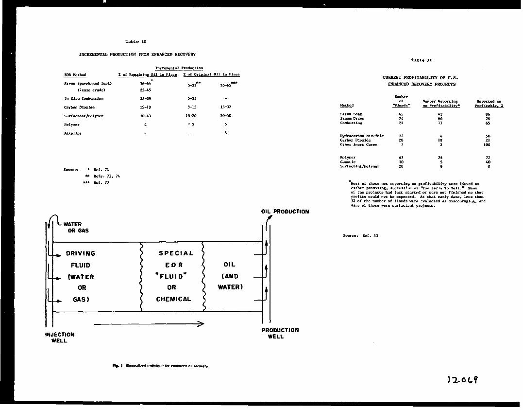
Table 15
lXCS2WSNTAL PRODUCTKW FROM SNi2ANCSD SSCOVERYTable 16
EOR Hethod
Steam (purchasedfuel)
(leasecrude)
In-Situ Cmlmst Ion
CarbonDioxide
Surfactant lPOlymer
Polpmer
Alkaline
Source: * Ref. 71
~ Refs. 73. 74
~ Ref. ?7
IncrementalProductio?
Z of Rema2ningOil in Plac_e Z of OriginalOil in Place
36-64* 5-35****
35-6525-45
CUSSSNT PSOFITASILITY OF U.S.
SNSANCSD IOICOVSSYPSOJSCTS
28-39 5-25
15-19 5-15 15-32
30-43 10-20 30-50
4 <5 5
5
Numberof NumberReporting
-dSeporcedas
‘Floods’V on Profitability* Profitable.%
SteatnSoak 45 42 86SteamDrive 74 60Combustion 21 17 z
Hydrocarbonxiscible 12 4 50CarbonDioxide 28 19 21Other l“ert &.ses 7 2 100
Polymer 47 25 72Caustic 10 5 40.%rfactantlPOlymer 20 9 0
*Most of thosenot reporting on profitability were listed aseither promising,successfulor “TOO SarlyTo Tell.“’&nyof the projectshad just startedor were not finishedso thatprofitscouldnot be expected. At that earlydate, less than3% of the numberof floodswere evaluatedas disco”rsging,and~W Of t~se were surfactantprojects.
OIL PRODUCTION#
* DRIVING
FLU1O
+ (WAIE!?
OR
+ GAS )
II > I. .
INJECTIONWELL
PRODUCTIONWELL
Source: Ref. 33
*. I-Generalized technique for enhanced0,1recovery

011 UISCISITY - CENTIPOISE AT RESERVOIR CONDITIONS
EmEl~ VARIOUS TECHNN2UES POSSIBLEI
-v=~
. NO EST~BLISHED LIMITS
IEEzll — NOT CRITICAL IF uNIFORM —I
-1
— HIGH ENOUGH FOR GOOO ,NJECTION RATES —
m~~ PREFERREO ZONEI
=W::::::: :POSSIBLE: PREFERREO ZONEI
EEcl~/$$ PREFERRED ZONE1
m~fl~
: PREFERREO ZONE
10,000 1 I I 1 I 1 I 1 1 1t El
1.000It\I 00 \\
\\\\
\ AvERAGE10 \\
o.,,~202S303S404550SS 606S
CRUDE OIL GRAVITY. “A.P. 1. AT ‘O-F. 8 ATMOSPHERIC PRESSUREMm ha!
mg.2-GeneIal weNllOr wsm91y0f wIIG3cMa.alal lcO%aOmmm@encpm%%m
DEPTH . FEEW
2000 4000
m-ti~fl~--’or ‘ 87” ‘ ‘“”Y ~cDEEP ENOUGH ~ REQUIRED PRESSURE
m-fl~~~
: DEEP ENOUGH F(M RECWIREO PRESSURE
lEEE1-~DE”ENOuGH””OmMu“ESSURE 1-1 LIMITED BY TEMPERATURE
ml LIMITEO BY TEMPERATURE
al
PREFERREO ZONE
F===lm OEEP ENOUGH FOR REOUIRED PRESSURE 1
Ear1
WJRMAL RANGE