technic& notes no. 432 - digital library/67531/metadc54094/m2/1/high... · interference....
TRANSCRIPT

?
-------
TECHNIC& NOTES
NATIONAL ADVISORY COMU.ITT3E FOR AEROi?AUTICS-
NO. 432
. . . . .
DRAG TESTS OF 4/9-SCALE I1ODEL EiiGINE NACEI,LES
WITH VARIO?JS C!O!7LINGS
By Ray WindierLangley Memorial Aeronautical Laboratory
●
.—
WashingtonOctober, 1932
, “’?
1;
,

lll!illlMm(~fll~~~[~ll~““:::--”-,’“ ‘---‘- -------_______,..:,. 3 11760i425 5823 —. .—
NATIONAL ADVISORY COMMITTEE FOR AERONAUTICS
TECHNICAL NOTE NO.
DR.4G TESTS OF 4/9- SCQE KODEL
432
ENGINE NACELLES
‘WITH VARIOUS COWLINGS
By Ray Windier
SUIRMRY
Results are given for drag tests of 4/9-scale modelradial air-cooled engine nacelles made as a part of a gen-eral investigation of wing-nacelle-propell er interference.A small nacelle of the type commonly used with exposed ea-gine cylinders was tested with various forms of cowlingover the cylinders. The effects of cowling-ring positionand of angle of ring c“hord to the thrust line were inves-tigated. An N.A.C,A. cowled nacelle and a smooth bodywere also tested.
The results are given at 50, ’75, and 100 miles perhour for -50, 00, 50, loo, and ~50 ~g~e of ~irtch,
INTROiXJCTION
Hodels of two air-cooled engine nacelles with variouscowlings have bean tested in the propeller-research tunnelof the National Advisory Committee for Aeronautics as apart of a general investigation of wing-nacelle-propellerinterference. Although the addition of nacelles to anairplane generally introduces interference problems, it isconsidered advisable to give the results of the drag testsof the nacelles alone without interference in this reportas a contribution to general information o~ aerodynamicresistance, It should be borne in mind that these resultswere obtained with the propeller removed. The reader isreferred to the reports on the gei~eral program (reference1 and others to be published in the near future) for thepraotical application of nacelles to airplanes. (See alsoreferences 2, 3$ and 4.) The results of drag tests on anumber of small -model nacelles ere already available. Theclose check of two of the 4/9-scale combinations testedwith full-scale results gives assurance that the values

. ..-.
2 N.A. C.A.;”Technical NOta.-NO.4Z2
. . . . ... . -x
,
,_
obtained for the other combination?,. especially with thering cowlings, should be close’ to those for the full-scalecondition. This check is attributed to the large scale(4/9) of the present models and the fairly accurate repro-duction of Gngine details.
TWO nacelles were,used. The first was similar to theconve-ntional types which have exposed cylinders; the secondwas a larger one which, when used”with a hood, constitutedan M.A.C.A. cowled nacelle. Both nacelles were 4/9-scalemodels of Wright J-5 engine nacelles reported in reference3, and were tested with various types of co’ivlingover theengine, which was reproduced in considerable. detail. Asmooth body (without. engine oyl,ind~rs) was .51s0 tested,Tes$’results.are.,g$ven in pounds ,dr.a&of the rnode.ls‘at sev,- ,ep;~l,air..sp,ee.ds.,upto 10Q rnil.esper hour.
-. -. -
APPARATUS AND METIiOI!S
A description of the 20-foot propeller~research t?mnel _and methods of testing may be found in reference 5. Thenacelles were supported by tubes attached. to.the regular,airfoil supports. (See fig, 1.) TO these tubes were at-
●
tached short arms bolted ‘to the end of the ver”tical sup-ports. Suitalle holes in the arms permitted the angle ofpitch to be adjusted to the desired values.
●
With this ar-rangement it was not necessary to use a sting and there-fore the tare drag was reduced. In making the tare-dragtests the nacelles were supported by wires fre,e of thetubes.
—
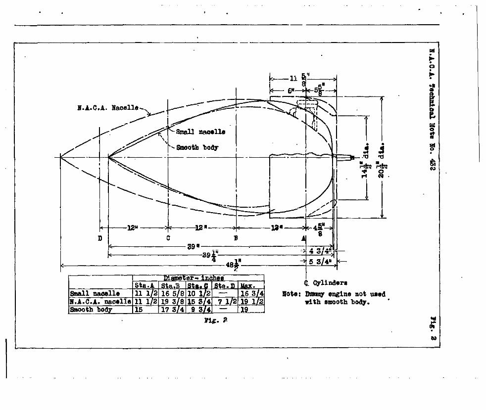
Figure 2 shows the nacelles used and gives their prin-cipal, dimensions. The larger nacelle ha,d’a maximum diameterapproximately equal to that of the engine. This nacelle,‘was tested both with the hood (ring) in place and with ifremoved, the former arrangement constituting an N.A.C.A.cowled nacelle. The conventional nacelle (hereafter calledsmall nacelle) had a qmall diameter back of the cylindersand ‘a little over -half ,the.f,in,area of the cylinders ex-posed. This:gq~e>:le ,W+S test,?d wi,th the cylinders exposedand with the..h,oo,das .previouqly,,;used on the. N.A.C.A. cowled,...nacelle as well as.with various for-insof ri”ag cowlings, Asnooth body without engine cylinder-s was also tested as ithad been used in the general progr&m.
— ,,.
,,,.
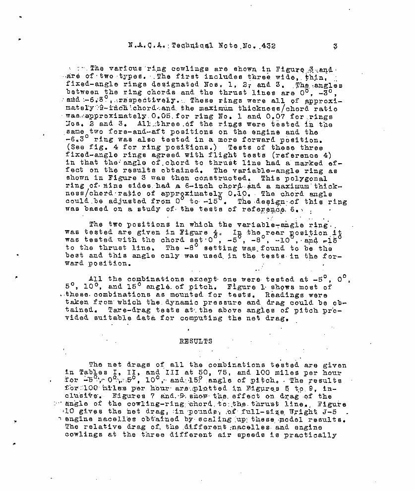
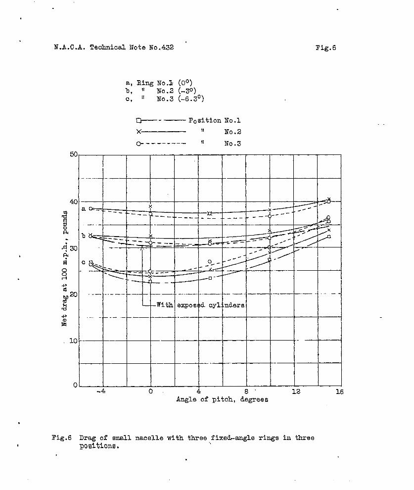
:-’.The various’ ri,ngcowlings are shown in Eigurq,,:3..:and..Ar8 of-two types. ~.The first includes three “wide, .~hin,fixed-angle rings designated Nos. 1, 2; and 3. ,~h~..,anglesbetween the ring chords and the thrust lines are 0°, -3°,add :-6;3°, ,:rs”spectivel.y..,These rings were all of ~pproxi-n.atexy .:~-iticli’.chord~.and.the maximun thickneqs/chord ratiomas.::approximately. 0.05. for ring No. 1 and 0P07 for .,ringsXos. 2 and 3. A1l._%hree.Qf the rings were tested ~n *Q8sane two fore-and-aft positions on the engine and the,-6.3° ring was also tested in a more forward position.(See fig. 4 for ring posi%idns. ) Tests of these threefixed-angle rings agreed with flight tests (reference 4)in that the: angle of,c~ord to thrust line had a marked ef-fect on the results obtained. The variable-angle ring asshown in Figure 3 was then constructed. This polygonalring of.fiine sides, had a 6-i~eh chor.d..~d a maximxn’thick-ness/choddra$io of appr~xinatel~ 0.,1.0. The chord anglecould.he adjusted from O to -15 . The .degi.+.n:.ofthis ringwas based on a study of. the tests of referezme, 6.-. : ......_
.., ~ . .The two positions in which the varia%le~a&gle ring”..
was tested are given in Figure $,, 1~ theorear gosi$ion i~was tested with the chord s6t.O , -5 , -8 , -10 ,.apd ~1~to the thrust line. The -8° setting wa.s.found to be tilebest and this angle only was used. zn the tests. in the for-ward position. ,
,. ..
All the combinations except. one were- tested at -5°, 0°,5°, 10°, and 15° ang16. of pitch. Figure 1 sh?ws most of
,.these.combinations as mounted for teets. Readings weretsken from” which the, dynamic pressure and drag could be ob-tained. Tare-drag tests at,.the a,bove angles of pitch pr-o-vided suitable data for computing the net drag.
,
RESULTS,,
.-
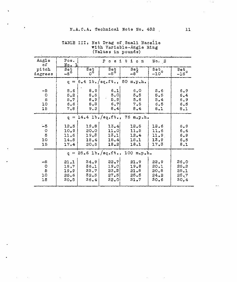
The net drags of all tbe combinations tested are givenin Tables I, II, and 111 at 50, ?5, and 100 miles per hourfor ~%~i,e0°:,;,50,10°;.,an&:,.150angle of :pi~ch. . The resultsftor::100hYle:s per Eour. ars,:pl~~tted in T.igure.s 5 t.o,b, in-clu”si%a.. Figures 7 a-nd.’9-,show. the. effect on drag of the
.,,.an’gle of the cowling-ring: :c”hord.t“o::th.e.thrust line,.. Figure~10 giv8s the net drag, :in pounds., ;o,f.full-size. l’?~,ightJ-5 .
~ engine nacell”es o%t’afned by sca:ing up: these, .podel results.The relative drag of, the ,cii.fferent:n&celles. and enginecowlings at the three different air speeds is practically
,.., . . . . . .
4 N.A. C.A. Technical Note No. 432.
..
the same; since’ the percentage ‘accuracy. is the greatest at100 °miles per hour, the discussion following has been tak-.en f~om the results at this speed only.
.“.
Tne results that are given have been taken froa fairedcurves and are believed to ‘lb accurate to within iO.2pound as the average deviation of the test points from thefaired curves did not exceed this amount.
DISCUSSION.,
Effect of Body Shape and N.A.C,A. Hood
.“---- .“.
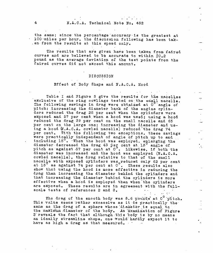
Table I aid l?igube 5 give the reeults for ~~e n.acell.esexclusive of the ring cowlings tested on the sria 1 nacelle.The following savings in drag were obtairied at O
h.angle of
pitch: increasing the diameter hack of the engine cylin-ders reduced the drag 25 per cent when the cylinders wereexposed and 57 per cent when a hood was used; using a hoOdreduced the drag 39 per cent on the small nacelle and 65per cent on the large one; increasing the diameter and us-ing a hOQd @.A.c.A. cowled nacelle) reduced--the drag 74per cent. With the following two exceptions, these savingswere practically independent of angle o,fpitch up to andincluding 15°. ‘When the hood was employed, e~larging thediameter decreased the drag 43 peg cent at “15 angle o-fpitch as ’against .57 per cent at O . Likewise, if both thediameter was increased and the hood was employed (N.A.C.A.cowled nacelle), the drag relative to that .of the smallnacel~e with exposed cylinders wasoreduced only 62 per centat 15 as against 74 per cent at O . These results alsoshow that using the hood is more effsctive in reducing thedrag than increasing the diameter behind ths cylinders andthat increasing the diameter %ehind the cylinders is moreeffective when’s ho’od is 6mployed than when-the cylindersare exposed. These results are in agreement with the full-scale tests of references 2 and 30 . . . .
...s,,’ ,.
The drag of “the snooth body was 8.6 2“’ou-n~~s’at Co ‘.p~tch.This value seems rather excessive as it IS practi’cal”ly thesane as the drag of a sphere whose ‘di.aiibtbris equal. “to,“the nax’irntim.d’iameter of the body, All“b’xatiiiia’tionof Figure2“reveals the fact that .aIthoughthis “body is by no meansan ideally streamline shape, one would” hardly expect it tohave as high a “drag a& that measured. - --
—
.—
—
.
-—.——
.

.
E,A, C,”A, T6ChZ1’i:C&”%Oie ‘~fO:“432’ 5
.,. flff’6ct,(jf’R’in&s - ‘ “.O .~j “-,.. ‘, .,’.,.... ,.’. ..,.. ,“. ” .“”’ .,, ,,,. .,. . .. . ...” .. .,.
~Ther”e.is & ‘pop’ular bel$r,ef”tlat almost any -kind. of a‘-ring cowling ‘will’reduce tlie drag of a radial en&in o.. The
““fallac,y of this lielief for t%e. condition witliout a prop”c$l -
le’r is, shown by the results obtained wi’tQ rings -’to’s,’1 “~-ld‘2’.and?“ith the .vakia~-le-angle ri.n~“set O ,~-“‘At 0? ‘.dn”~o.ofpitch’ these rings ‘increased the drag over “that with the”’ :cylinders exp,o.sed. -,RingNo. 3 in the QSst location reducedthe d.r+g ~.5--poutids,or 25 ~,er cent. The effect of ‘:*heford- and=”aft position- of the ring~”is s“htin in Figure “6‘and it wil~ be o%s”erved “that moving the “r’ing formard’”in-creased the drag with rings Uos. 1 and 2, and reduced t-hedrag with ring No. 3. Figure ‘7, in which the values ofdrag are replotted to show the :&ff&ct of “ring-chord angleto the thrust line for the three rings in position No. 3,sho,ws that furtherr reduction could B? expected .if the ring-chord ‘angle:~ere.,iricreased. These r&sultq,- v~ikh. aT-e alsogiven in Table, II, ‘indicate that the fore-an@ .Jaft locationof the .,ring affects t’he--drag to a. slight ektent ““lj~~h:?af“:the an’gle “o-fthe ring chord to the fhrust I.irioi% -a “mo”re.decisive-factor in drag reduction; -
,.. .,..,. . . .... ... ...., .,.. ..
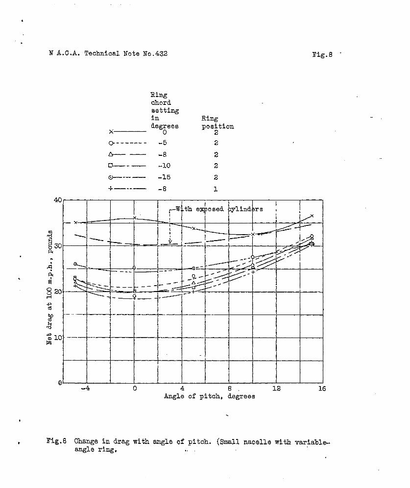
The results withthe”v ariab~o-angl~’r$ng will: be.”fbundin Ta%le III and Figures 8 and 9. In the rear position the
● optimum anglo of chord incroasod ?ith the angle of pitchas shown in Figur&’ 9’0 The -$0 chor’d”angl”o was selactodand run in the forward position where the drag was found tobe slightly lower. than in tl+o rear one. (See Table 111and fig, 8.) l?ith this optimum angle and-position ti~odrag was reduced”38 p$r cent over that with the cylindersexposed. None of the other angles were tried i.n the for-.,ward position.
Comparison” of Rings and lT.A.C~A, Hood - .,. ., ,.
The following comparison is made between the ringsand the N.A.C,A., hood which was tested on t-ne suall nacelleas a natter of interest.’ With the hood, and ther~ngs inposition No. 1, the leading edge of the cylinder cowlingwas 5-3/4 inches ahead of the center line of the cylinders.(See figs. 2 and 4.) This was the maximum forward locationthat could be used and have clearanbe””for the” propeller a$high pitch settings, ~ith the variable-angle ring set -8in position No. 1 the drag was 18.7 pounds at 0° aiiglo of,... .

.
.
6 N,A. C.A, Technical N-o,t.eNo. 432
pitch, which Is only 0,2 pound higher than ..with the hood;thorofore, there is little choice betwe~n t-he two forcruising or high speed, However, the drag “increased morerapidly with-the ring than ‘iv”iththe. hoodas the angle of‘pitch.was increased until at.15° it” was almost 11 timesthat with the hood. Hence. the hood appeared to ~e ~he”bet-ter cowling for general-purpose use. %bseque~t te%ts ofwing-nacelle combinations ha~e verified this both” with thepropeller oper,ating and with’it r.enoved. (Refi-ren’ce 1.)
Since tests with the.sm~l~ nacelle showed that the,N.A.C.A. hood was superior to all of the rings tested,the rings were not tested on the large nacelle.
.....Effect of A~gle of P-it~h
,.. .., . .. .
All the combinations show the usual increaye in dragwith angle of -pitch. A systematic analy$isureveals theinte~ksting fact that the lower the drag of_the combinationat 0 pitch the higher is the percentage increase in dragas the angle of pitch isoincreased. The combination whichhad the lowest drag” at O pitch had, however, the loweetdrag throughout the entire pitch range;
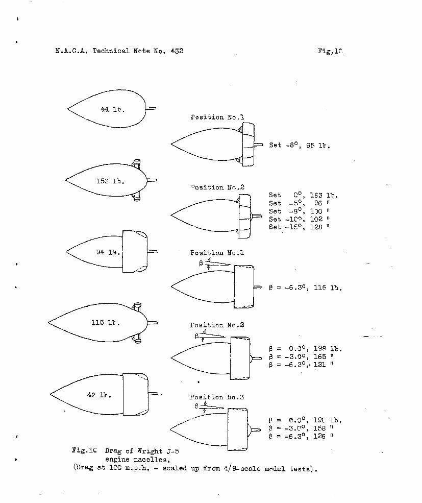
The full-scale drags at 0° angle of ,pitch of all thecombinations tested as obtained by scaling up these modeltests are given in Figure 10. Reeults of some previousfull-scale wind-tunnel drag tests on J-5 engine nacellesare given in reference 3. The following table giving thedrag (in pounds) at. 100, miles per hour shows a,close agree-ment between the 4/9-scale model tests reported hereinthose full-scale tests,
,,
Nacelle
Full-scal,e . Model dragdrag -- (4/9)2
ref; 3pounds . pounds
..Small nacelle - exposed , ... a.
-.
-.
—.
.
.
●
—
——
. ‘.—
and
:
cylinders 155’ “ - 153 ‘ .-
N,A,C.A, nacelle.
43” 40 -.
..,
.
r

.
X.”A.,C.A, Technical’ Note. No., 4.32
Other Considerations
In.the general program of wing-.nacelle-prope~ler ip-.terference, propeller tests, especially with tandem pro-peelers,,, have shown that the propulsive efficiency is af-fected. by.“t~e,anglp of the ring chord to the thrust line.This effect is presumably caused hy the fact that theslipstream “of the propeller changes the. direct.io~’,,o,~:aipflow over the ring and consequently the drag. .-”It.has beenfound that the cowling tha$ gives the >owest~ d“rag withoutthe propeller is not always the %es~ combination when usedwith a propeller. This” is a partial exp~anation. of why.some cowlfngs have been known to increase the, drag withthe propeller removed i.ntunnel tests. but have shown in-crease’s in speed when tested in free flight. At least itis evid”sm:t.that A nacelle cowling should ,nbt be .selecteodentirely: froh a consideration of”“drag and that it is nec-e..ssary.ta .cons3der the. dompl.ete ~ower unit. including na-celle and propeller,
.. .. ...”.,
Langley Menorial Aeronautical Laboratory,Nationai Advisory Comnittee for Aeronautics,
Langley Field, Vs., September 22$ 1932..,., .. :. .
,.,1.
,
.
8 N.A. C,.A. Technical Hote ,Ho..43.2
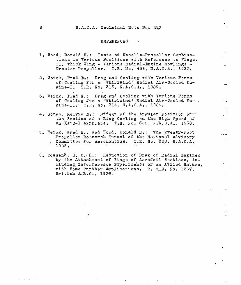
REI?~,EI?CXIS. .
1. 17aod, I)onald E. : Tests of Nac,elle-Propeller Combina-tions in Various Positions with Reference to YingscII. Thick fling - Various Radial-Engine Cowlings -Tractor Propeller. ToR, NO, 436, lT,A.C.A. , 1932.
2. 17eick, Fred E.: ‘Drag and”Cooling with Various Formsof Cowling for a 1117hirlwindt!Radial Air’-Cooled En-gine-l. T.R. NO. 313, N,A.C.A. , 1929.
3. 17eick, Fred E,: Drag and Cooling with Various Formsof Cowling for a ‘Whirlwind’l Radial Air-Cooled En-gine-11,” T.R. No, 314, IT.A.C.A,, 1929.
4. Gough, Melvin N.: Effect. of the Angular” Position of--the Section of a“Ring Cowling on the .High Speed ofan XF7C-1 Airplane. TaN. NO. 355, HoA.C.A. , 1930.
“ ‘5. Weick, Fred E., and wood, Donald E.: The !I!wenty-FootPropeller Research Tunnel of the National AdvisoryCommittee for Aeronautics. T.R, No. %00, N,A,C.A,1928 ●
—
6. Townen~, H, C.H.: Reduction of Drag of”Radial Engfnesby the Attachment of Rings of Aerofoil Sections, In-cluding Interference Experiments of an Allied Nature,with Some Further Applications. R, &__M, NO. 1267,British A.R.C., 1929.
.
-.
.“
—
—
-—
.
.\

.
.
.
N.A.C.A. Technical Note No. 432 9
TABLE I. Net Drag of Various Nacelles(Values in pounds)
Angleof
pitch
degrees
Small Small Large LargeSmooth nacelle nacelle nacelle nacellebody with with with with
exposed N. A. C.A, exposed N. A, C.A.cylinders hood cylinders hood
-505
1015
-505
1015
% = 6.4 lb./sq.ft., 50 m.p.h.
1.9 8.6 4.6 .-2.2 7.8 4.6 6.02.2 8.5 5.5 6.02.6 9.0 6.1 7.03.0 9.6 6.4
Q = 14.4 lb./sq.ft., ‘75:m.p.h.
4.2 18.’7 10.94.9 17.1 1004 13.54.9 17.7 10.9 13.35.8 18.S 12.0 15.1”8.0 19.9 13.1
3.82,22.53.14.0
4.94.65.36.07.6
I c= 25.6 1%./sq.ft., 100 m.p.h.
-5 7.3 33.2 19.90 8.6 30.2 18.5 22.85 8.8 30.9 18.6 23.4
10 10.4 33.0 20.3 25.515 14.3 34.3 22.6
7.27:98.4
1:::
.

.
.
‘Angleof
pitchdegrees—
-505
1015
-505’
1015
-505
1015
N. A. C.A. Technical Note No. 432 10
TABLE II. Net 13rag of Small Nacellewith Fixed-Angle Rings(Values in pounds)I I —
Ring No. 1 \ Ring No. 2 I Ring No.
Pos. Pos. I Pos. pos. I poaaNo. 2 iToO 3 No. 2 INo. 3 No. 1
~ = ‘6.4 lb.(/sq.ft.’, 50 m.p.h.
10.0 10.4 8.2 8.2 7.010.5 9*7 7.6 .10.5 9,510.8 9.510.9 10.2
‘:: 3~~q =
22.122,522.722,3.23.4
q =
38.639.137’.638.240.4
..—
14.4 lb./sq.ft., 75 m“.p.h.
22.1
- .J.l
18.6 18.4 I15.2
21.4 1?.6 17.5 13.021.3 1’7.6 17.5 13.321.3 18.5 18.2 15.522.7 ,20.2 20.5 18,5— ..
25.6 lb./sq.ft.~ 100 m.p.h.
---L38.5 33.037.5 32.637.5 31.536,8 32.740,0 36.1
32.631.130=9
3.2.236.5
.—
26.722.723.5”27.532.4
I?os.No. 2
6.66.06.37.78.8
14.913.514.316.619.5
26.623.825.328.833.9
3
Pos.No. 3
7.16.36,9‘7.99.6
15.514.015.917,520.5
26.524.9
27.030.135,7
.
1
.
.
.,
N.A. C..A. Technical Note No. 432 . 11
TA.BLh 111: Net Drhg! of ,Small haceilewith Papiable-Angle Ring’(Values in pounds)
of ‘ No. li *pitch Se; “ Se; Set Se~ Set —s7
degrees
+
-5° I -10°%0
-8 -15°
~ = 6.4 lb./sq.ft., 50 m.p.h.~II
-5 , 5.6 8.9
L’ ~
6.1 6.0I :::
6.90 5.2 8.5 5.0 5.5 6.45 5.7 8.9 “ 5.9 5.6 5.4 6.9
10 6.6 8.3 6.7 7.5 6.5 6.515 7.8 9.3 8.4 8.4 8.1 8.1
.—I q=”14.41b~/sq.ft., 75 m.p.h. \
] q=25.61b. /sq.ft., 100 m.p.h. I
-5 21.1 34*9 22.7 21.9 I 22.9 26.00 19,7 36.1 19.0 19.8 I 20.1 25.2!5 19.9 33.7 23.3 21.8 20.8 25.1
10 25.6 32.5 27.5 25.5 24.2 25.,715 30.5 36.4 32.0 31.7 30.6 30P4

.
.
.
.
●
✎
☛
N.A.O.A. Tec?hnioal Note No.432 Fig. 1
A, Small naoelle with exposed B, Small naoelle with N.A.O.A.oylinders hood
C, N.A.CI.A. nacelle with hood D, N.A.O.A.bowling removed naoe lle
.. .
—
—
—
Dhmet er. InchesSta.A sta,B ta. C Ma. n k @inders
Mex&Mll naalme 11 1/2 16 5/8 10 1/2 — 16 i/4 Mote: IhamIYengine not used
li.A.C.A. nacelle 11 l/2 19 3/8 15 s/4 7 1/2 19 1/2
~th body 15with cmooth body. “
17814 9 3/4 —
I

.
.N.A.C.A. Technical Note No. 432 Fig;3
—.
J—.
~,----------Ring No.1
G%-ld
:cI
.—
.-
,------ ----- -
Ring No.2
1
.-. —
IT-——
LL—— L-------------
Ring NO. 3
p-lm—37’1_8°~
I
—..—
.
k. Variable1 ~l:8;ing
.
I ,
Fig.3 Ring cowlings.

*
.
.
.
.
,
lf.A.O.A. Wia4mUal Mote SO. @ rig. 4
—Poe. Ho. 1
— Pos. m. 2
—POS* Eo. 3
I’lxedangle rings
,Variableangle ring
—Pos. No. 1
Pos. No. 2

1
.
,
.
.
.
N.A.C.A. Technical.Note No.432
4(
.
——.-.
—C&
.—. ..
*=
.—
x
0.A#
i
.—
._
,—~
.——
—.—
.—
N.A.C.A. nacelle
Smooth body
Small nacelle,with N.A.C.A. hood
N.A.C.A. nacelle,hood removed
Small nacelle,e~osed cylinders
1=___—..‘1——..—
+
T—...—.
0
——
— —-
,—
.——
—
——- ——- -—
—— -— —
— - e
-J
—,
4 8Angle of pitch, degrees
Fig.5
t
!——
12 16
Fig.5 Change in drag with angle of pitch, (Various nacelles)
,
.
N.A.C.A. Technical Note No.432 “
,
50
442
10
.. ... . ...
ak
—.. .
b%
c%
-.--.
----
,.,,,.
..—
0
. .. .
---
.-—
~--P
---
-
,. -—.
-----
.——
——
a, Ring No.3%, it NO.2c, 1’ NO.3
(00)(-30)
(-6 . 3°)
n-———— Position No.1
x 11 NO.2
o- ----- --- 11 NO.3
+
T-------.—x
T-----——+.-_-,_--
x—-.
,—. .—
With
~
. —— -——
——
0.
JA---— ____ ---- .-- —-
. ..—
/.
x — .----~—--— . A
.-a
o--”
/13--
-. .—-. .-. — ..-— .— - —,—
expos a Cyl: -riders
-—
--
—. -—— -----
4 8“Angle of pitch, degrees
$.-”
----
a“ <,-
.
.—. .—
.-.— —- ..—
-—
..—
12
Fig.6 Drag of small nacelle with three fixe&angle rings in threepositions,
,.
+5---
.,._.
16
.

.
,
.
,
●
N.A.C.A. Technical Note 1;0.432
x---------
0
+—
~ -—
+---—
.;0
0°so
10°
Angle of ring chord to thrust line,degrees
17ig.7 lZffectof angle of chord to thrust line on drag. (Small nacellewitinrings Nos.1,2, and 3 in position No.2).
.—___
.
NA.C.A. Technical Note No.432 Fig.8 “
Ringchordsettingindeg:ees
x
c-..---- . -5
+— -8
-— -10
@-–——— -15
+—--— -8
~-w
—II
— x— ~ — 5 —’ t\I
- ~ Ii— Iv—Y -— ~
[
— -- ---- +!
<. _-,___ _-i <r-— -. &
1-—
i9— -~
—...— --— .-.+___
.—
—
Ringposition
2
2
2
2
1
th ez$osedI Ipylind3rs t ,
I1I
I‘x>. .
Ix
_ ‘~ !-
-1—
4-- /“
H“A
>+
t-’
---1-
1
-4 0 4 8, 12 16Angle of pitch, degrees
.
Hg.8 Change in drag with angle of pitch. (Small nacelle with variable-angle ring. ..

N.A.C.A. Technical Note No.432
x--------.;0~ 0°
&——— 50
D-——— 10°
+—--— 15°
— .-30
20
10
0 . ——0 -4 -8 -12 -16
Angle of ring chord to thrust line, degrees
Fig.9 Effect of angle of chordto thrust line on drag..(Small nacellewith variable-~le ring in position 1$0.2
3
#
N.A.C.A. Technical Ncte No. 452 Fig,lC
Fosition No.1
‘osition HrI.2
=El-Fosition No.i
-& ----
al----Fosition Nc.2
Ia ------.*Fig.lC Drag of Wright J-5
engine nacelles,(Drag at lCC rn,p.h, - scaled up from 4/9-scale
Set co, 183 1%,Set -50, 96 II
Set -so, 1’3GIIset -lCQ, 102 11Set -lEC, 128 ‘1
.—
.@ =-6.3°, 1151?).
.—.. .
E = 0.’30,198 lk.
d = _3-90, 165 II
B = -6.30,9121 ‘~
P = ().()0, 19C 11.—
~= -3.f2°, 158 nE = -6.3°, 126 1’
nmdel tests).