techline as™ design guide - netafim as design guide - 20… · submain sizing 13 zone water ......
TRANSCRIPT

TECHLINE AS™
DESIGN GUIDE
A complete guide for the design of on-surface and sub-surface drip irrigation systems using Techline AS™.
T E C H L I N E A S ™ D E S I G N G U I D E
NETAFIM @[email protected] 21/12/2009 2
TABLE OF CONTENTS
INTRODUCTION 4OVERVIEW 4WHAT IS TECHLINE AS™ 5
Applications 6Specifications 6Technical Data 6
DESIGN CRITERIA 7Site Survey 7Point Of Connection 7Which Techline AS™ Product Should You Use? 8Types Of Layouts 9“GRID” Layouts 9“LITE” Layouts 9What Do These Layouts Have In Common 9Standard “GRID” Layout 10Standard “LITE” Layout 10How To Calculate Equal Techline AS™ Row Spacing 10Length of Techline AS™ Rows 11Centre Feed “GRID” Layouts 11Other “GRID” Considerations 12Mainline Sizing 13Submain Sizing 13Zone Water Requirements 14Techline AS™ Flow Charts 14Fittings 15Pipe Stakes 15Line Flushing Valves 16Automatic Line Flushing Valve 16Manual Flushing Valve 16Air/Vacuum Release Valve 17Filters 18Pressure Regulating Valves (PRV’s) 18Pressure & Flow Checks 19Line Indicator Flag 19Slopes and Mounds 20Techline AS™ in Turf (SDI) 21Techline AS™ in New Sodded Turf 21Techline AS™ Above and Below Grade 21TechFilter (SPU) 22Techline ASTM (Bioline AS™) 23
TECHLINE AS™ INSTALLATION DRAWINGS 24Square Layout 24Centre Feed Layout 24Triangular Layout 25Typical Island Outlet 25Odd/Curve Layout 26Circular Layout 26Headwork’s with RPZ 27Headwork’s with DCV 27Control Valve (Above Ground) 28Control Valve (Sub-Surface) 28
T E C H L I N E A S ™ D E S I G N G U I D E
NETAFIM @[email protected] 21/12/2009 3
TECHLINE AS™ DESIGN FORMULAS 29Formula 1.1 Estimated Total Length Of Dripperline 29Formula 1.2 Application Rate 29Formula 1.3 Number Of Drippers In A Zone 29Formula 1.4 Flow Per Zone 30Formula 1.5 Estimated Total Zone Flow 30
CALCULATING TECHLINE AS™ RUN TIMES 31
TECHLINE AS™ INSTALLATION GUIDE 35Specifications 35System Maintenance 37Techline AS™ System Inspection Checklist 38Techline AS™ Installation Tools 39
TECHLINE AS™ ACCESSORIES 40
T E C H L I N E A S ™ D E S I G N G U I D E
NETAFIM @[email protected] 21/12/2009 4
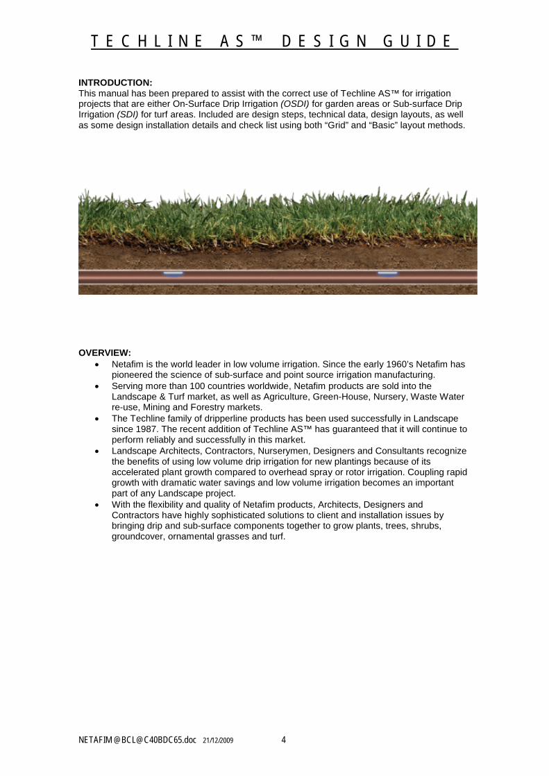
INTRODUCTION:This manual has been prepared to assist with the correct use of Techline AS™ for irrigation projects that are either On-Surface Drip Irrigation (OSDI) for garden areas or Sub-surface Drip Irrigation (SDI) for turf areas. Included are design steps, technical data, design layouts, as well as some design installation details and check list using both “Grid” and “Basic” layout methods.
OVERVIEW: Netafim is the world leader in low volume irrigation. Since the early 1960’s Netafim has
pioneered the science of sub-surface and point source irrigation manufacturing. Serving more than 100 countries worldwide, Netafim products are sold into the
Landscape & Turf market, as well as Agriculture, Green-House, Nursery, Waste Water re-use, Mining and Forestry markets.
The Techline family of dripperline products has been used successfully in Landscape since 1987. The recent addition of Techline AS™ has guaranteed that it will continue to perform reliably and successfully in this market.
Landscape Architects, Contractors, Nurserymen, Designers and Consultants recognize the benefits of using low volume drip irrigation for new plantings because of its accelerated plant growth compared to overhead spray or rotor irrigation. Coupling rapid growth with dramatic water savings and low volume irrigation becomes an important part of any Landscape project.
With the flexibility and quality of Netafim products, Architects, Designers and Contractors have highly sophisticated solutions to client and installation issues by bringing drip and sub-surface components together to grow plants, trees, shrubs, groundcover, ornamental grasses and turf.
T E C H L I N E A S ™ D E S I G N G U I D E
NETAFIM @[email protected] 21/12/2009 5
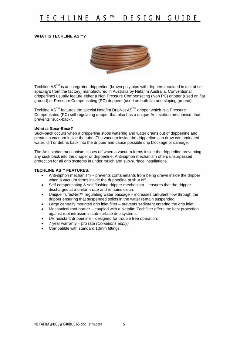
WHAT IS TECHLINE AS™?
Techline ASTM is an integrated dripperline (brown poly pipe with drippers moulded in to it at set spacing’s from the factory) manufactured in Australia by Netafim Australia. Conventional dripperlines usually feature either a Non Pressure Compensating (Non PC) dripper (used on flat ground) or Pressure Compensating (PC) drippers (used on both flat and sloping ground).
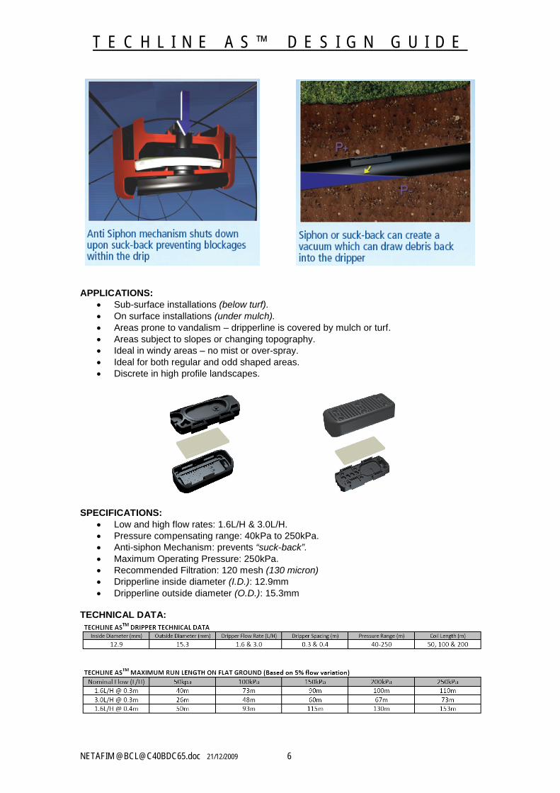
Techline ASTM features the special Netafim DripNet ASTM dripper which is a Pressure Compensated (PC) self regulating dripper that also has a unique Anti-siphon mechanism that prevents “suck-back”.
What is Suck-Back?Suck-back occurs when a dripperline stops watering and water drains out of dripperline and creates a vacuum inside the tube. The vacuum inside the dripperline can draw contaminated water, dirt or debris back into the dripper and cause possible drip blockage or damage.
The Anti-siphon mechanism closes off when a vacuum forms inside the dripperline preventing any suck back into the dripper or dripperline. Anti-siphon mechanism offers unsurpassed protection for all drip systems in under mulch and sub-surface installations.
TECHLINE AS™ FEATURES: Anti-siphon mechanism – prevents contaminants from being drawn inside the dripper
when a vacuum forms inside the dripperline at shut off. Self-compensating & self flushing dripper mechanism – ensures that the dripper
discharges at a uniform rate and remains clean. Unique TurboNet™ regulating water passage – increases turbulent flow through the
dripper ensuring that suspended solids in the water remain suspended. Large centrally mounted drip inlet filter – prevents sediment entering the drip inlet Mechanical root barrier – coupled with a Netafim Techfilter offers the best protection
against root intrusion in sub-surface drip systems. UV resistant dripperline – designed for trouble free operation. 7 year warranty – pro rata (Conditions apply) Compatible with standard 13mm fittings.
T E C H L I N E A S ™ D E S I G N G U I D E
NETAFIM @[email protected] 21/12/2009 6
APPLICATIONS: Sub-surface installations (below turf). On surface installations (under mulch). Areas prone to vandalism – dripperline is covered by mulch or turf. Areas subject to slopes or changing topography. Ideal in windy areas – no mist or over-spray. Ideal for both regular and odd shaped areas. Discrete in high profile landscapes.
SPECIFICATIONS: Low and high flow rates: 1.6L/H & 3.0L/H. Pressure compensating range: 40kPa to 250kPa. Anti-siphon Mechanism: prevents “suck-back”. Maximum Operating Pressure: 250kPa. Recommended Filtration: 120 mesh (130 micron) Dripperline inside diameter (I.D.): 12.9mm Dripperline outside diameter (O.D.): 15.3mm
TECHNICAL DATA:
T E C H L I N E A S ™ D E S I G N G U I D E
NETAFIM @[email protected] 21/12/2009 7
DESIGN CRITERIA: Designing with Techline AS™ follows the same basic rules as designing with sprays
and rotors. A point of connection (water connection point) must be established and its static and
operating pressure, flow rate and water quality recorded. Identifying the type of plants that are to be irrigated and grouping plants with similar
water requirements (Hydro-zoning) will ensure that maximum watering efficiency can be maintained.
Identifying the sites soil type, topography and micro climatic influences.
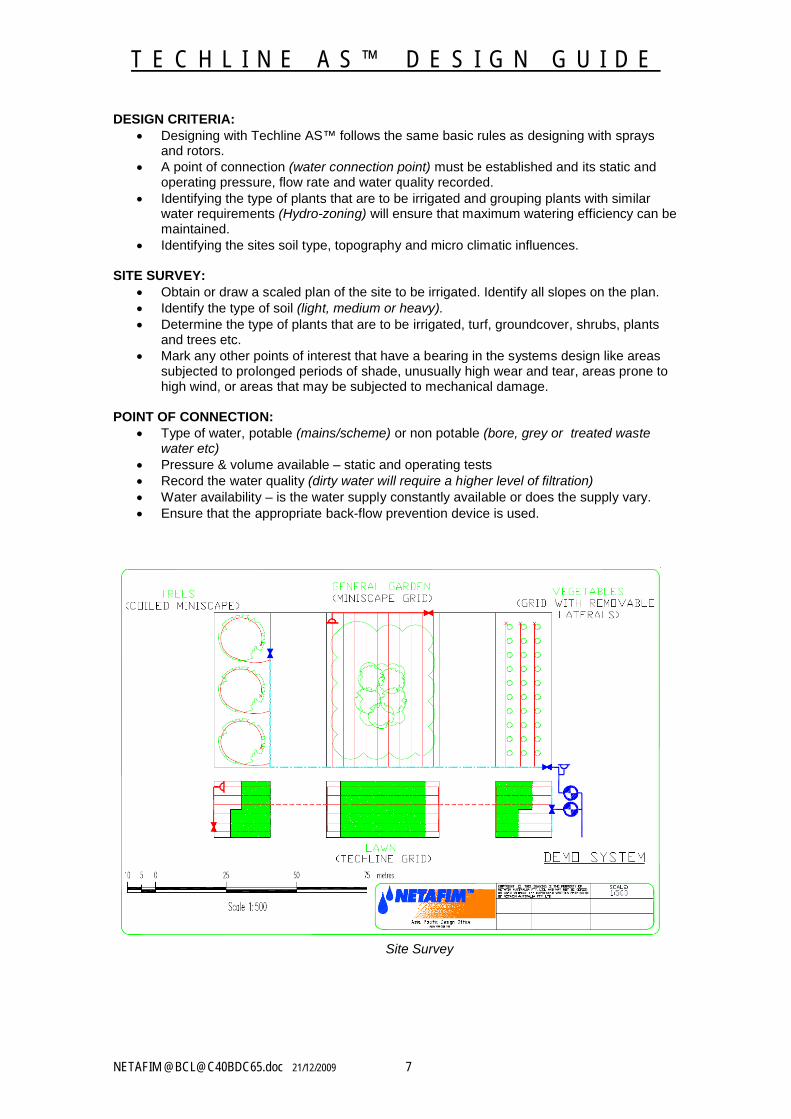
SITE SURVEY: Obtain or draw a scaled plan of the site to be irrigated. Identify all slopes on the plan. Identify the type of soil (light, medium or heavy). Determine the type of plants that are to be irrigated, turf, groundcover, shrubs, plants
and trees etc. Mark any other points of interest that have a bearing in the systems design like areas
subjected to prolonged periods of shade, unusually high wear and tear, areas prone to high wind, or areas that may be subjected to mechanical damage.
POINT OF CONNECTION: Type of water, potable (mains/scheme) or non potable (bore, grey or treated waste
water etc) Pressure & volume available – static and operating tests Record the water quality (dirty water will require a higher level of filtration) Water availability – is the water supply constantly available or does the supply vary. Ensure that the appropriate back-flow prevention device is used.
Site Survey
T E C H L I N E A S ™ D E S I G N G U I D E
NETAFIM @[email protected] 21/12/2009 8
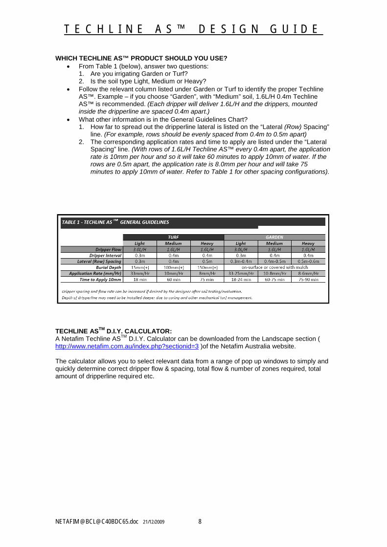
WHICH TECHLINE AS™ PRODUCT SHOULD YOU USE? From Table 1 (below), answer two questions:
1. Are you irrigating Garden or Turf?2. Is the soil type Light, Medium or Heavy?
Follow the relevant column listed under Garden or Turf to identify the proper Techline AS™. Example – if you choose “Garden”, with “Medium” soil, 1.6L/H 0.4m Techline AS™ is recommended. (Each dripper will deliver 1.6L/H and the drippers, mounted inside the dripperline are spaced 0.4m apart.)
What other information is in the General Guidelines Chart?1. How far to spread out the dripperline lateral is listed on the “Lateral (Row) Spacing”
line. (For example, rows should be evenly spaced from 0.4m to 0.5m apart)2. The corresponding application rates and time to apply are listed under the “Lateral
Spacing” line. (With rows of 1.6L/H Techline AS™ every 0.4m apart, the application rate is 10mm per hour and so it will take 60 minutes to apply 10mm of water. If the rows are 0.5m apart, the application rate is 8.0mm per hour and will take 75 minutes to apply 10mm of water. Refer to Table 1 for other spacing configurations).
TECHLINE ASTM D.I.Y. CALCULATOR:A Netafim Techline ASTM D.I.Y. Calculator can be downloaded from the Landscape section ( http://www.netafim.com.au/index.php?sectionid=3 )of the Netafim Australia website.
The calculator allows you to select relevant data from a range of pop up windows to simply and quickly determine correct dripper flow & spacing, total flow & number of zones required, total amount of dripperline required etc.
T E C H L I N E A S ™ D E S I G N G U I D E
NETAFIM @[email protected] 21/12/2009 9
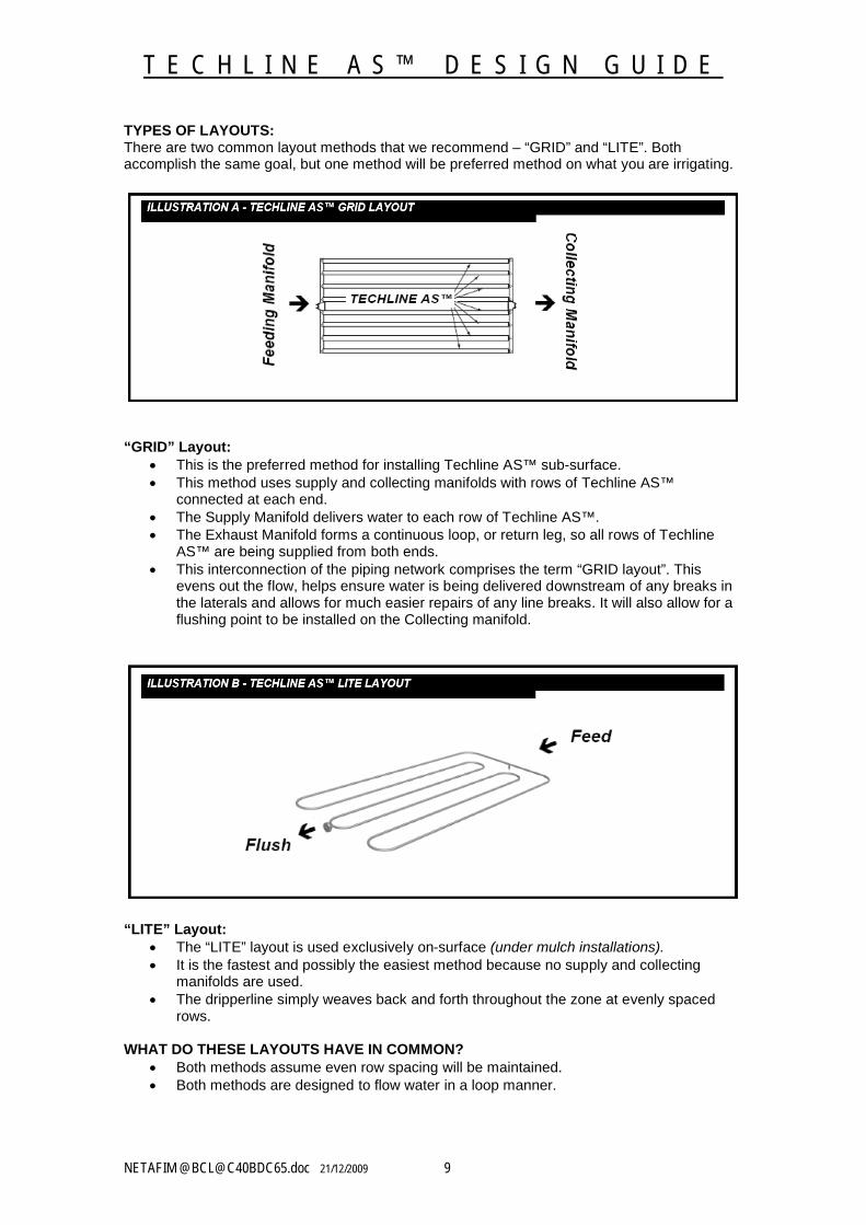
TYPES OF LAYOUTS:There are two common layout methods that we recommend – “GRID” and “LITE”. Both accomplish the same goal, but one method will be preferred method on what you are irrigating.
“GRID” Layout: This is the preferred method for installing Techline AS™ sub-surface. This method uses supply and collecting manifolds with rows of Techline AS™
connected at each end. The Supply Manifold delivers water to each row of Techline AS™. The Exhaust Manifold forms a continuous loop, or return leg, so all rows of Techline
AS™ are being supplied from both ends. This interconnection of the piping network comprises the term “GRID layout”. This
evens out the flow, helps ensure water is being delivered downstream of any breaks in the laterals and allows for much easier repairs of any line breaks. It will also allow for a flushing point to be installed on the Collecting manifold.
“LITE” Layout: The “LITE” layout is used exclusively on-surface (under mulch installations). It is the fastest and possibly the easiest method because no supply and collecting
manifolds are used. The dripperline simply weaves back and forth throughout the zone at evenly spaced
rows.
WHAT DO THESE LAYOUTS HAVE IN COMMON? Both methods assume even row spacing will be maintained. Both methods are designed to flow water in a loop manner.
T E C H L I N E A S ™ D E S I G N G U I D E
NETAFIM @[email protected] 21/12/2009 10
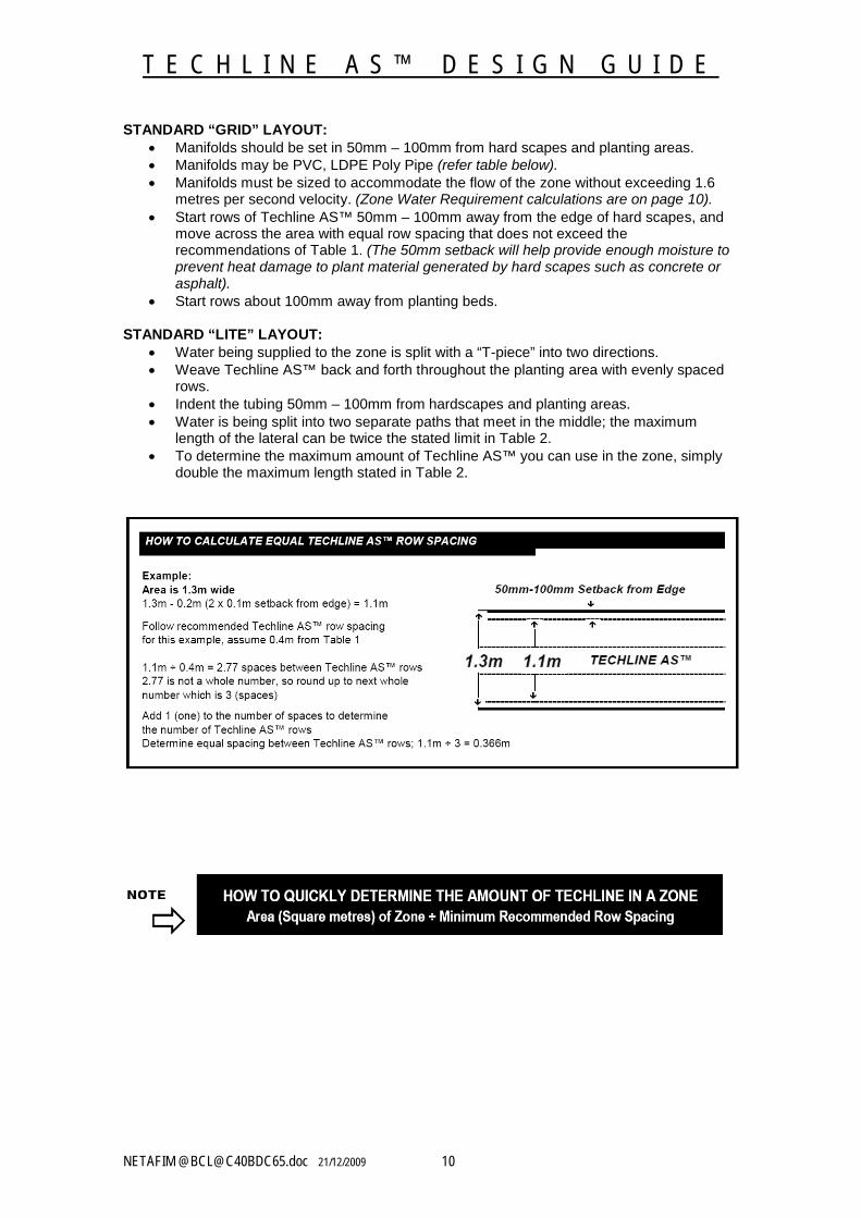
STANDARD “GRID” LAYOUT: Manifolds should be set in 50mm – 100mm from hard scapes and planting areas. Manifolds may be PVC, LDPE Poly Pipe (refer table below). Manifolds must be sized to accommodate the flow of the zone without exceeding 1.6
metres per second velocity. (Zone Water Requirement calculations are on page 10). Start rows of Techline AS™ 50mm – 100mm away from the edge of hard scapes, and
move across the area with equal row spacing that does not exceed the recommendations of Table 1. (The 50mm setback will help provide enough moisture to prevent heat damage to plant material generated by hard scapes such as concrete or asphalt).
Start rows about 100mm away from planting beds.
STANDARD “LITE” LAYOUT: Water being supplied to the zone is split with a “T-piece” into two directions. Weave Techline AS™ back and forth throughout the planting area with evenly spaced
rows. Indent the tubing 50mm – 100mm from hardscapes and planting areas. Water is being split into two separate paths that meet in the middle; the maximum
length of the lateral can be twice the stated limit in Table 2. To determine the maximum amount of Techline AS™ you can use in the zone, simply
double the maximum length stated in Table 2.
T E C H L I N E A S ™ D E S I G N G U I D E
NETAFIM @[email protected] 21/12/2009 11
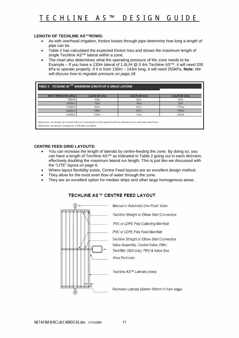
LENGTH OF TECHLINE AS™ROWS: As with overhead irrigation, friction losses through pipe determine how long a length of
pipe can be. Table 2 has calculated the expected friction loss and shows the maximum length of
single Techline AS™ lateral within a zone. The chart also determines what the operating pressure of the zone needs to be.
Example – If you have a 130m lateral of 1.6L/H @ 0.4m Techline AS™, it will need 200 kPa to operate properly. If it is from 130m – 143m long, it will need 250kPa. Note: Wewill discuss how to regulate pressure on page.18.
CENTRE FEED GRID LAYOUTS: You can increase the length of laterals by centre-feeding the zone. By doing so, you
can have a length of Techline AS™ as indicated in Table 2 going out in each direction, effectively doubling the maximum lateral run length. This is just like we discussed with the “LITE” layout on page 6.
Where layout flexibility exists, Centre Feed layouts are an excellent design method. They allow for the most even flow of water through the zone. They are an excellent option for median strips and other large homogenous areas.
T E C H L I N E A S ™ D E S I G N G U I D E
NETAFIM @[email protected] 21/12/2009 12
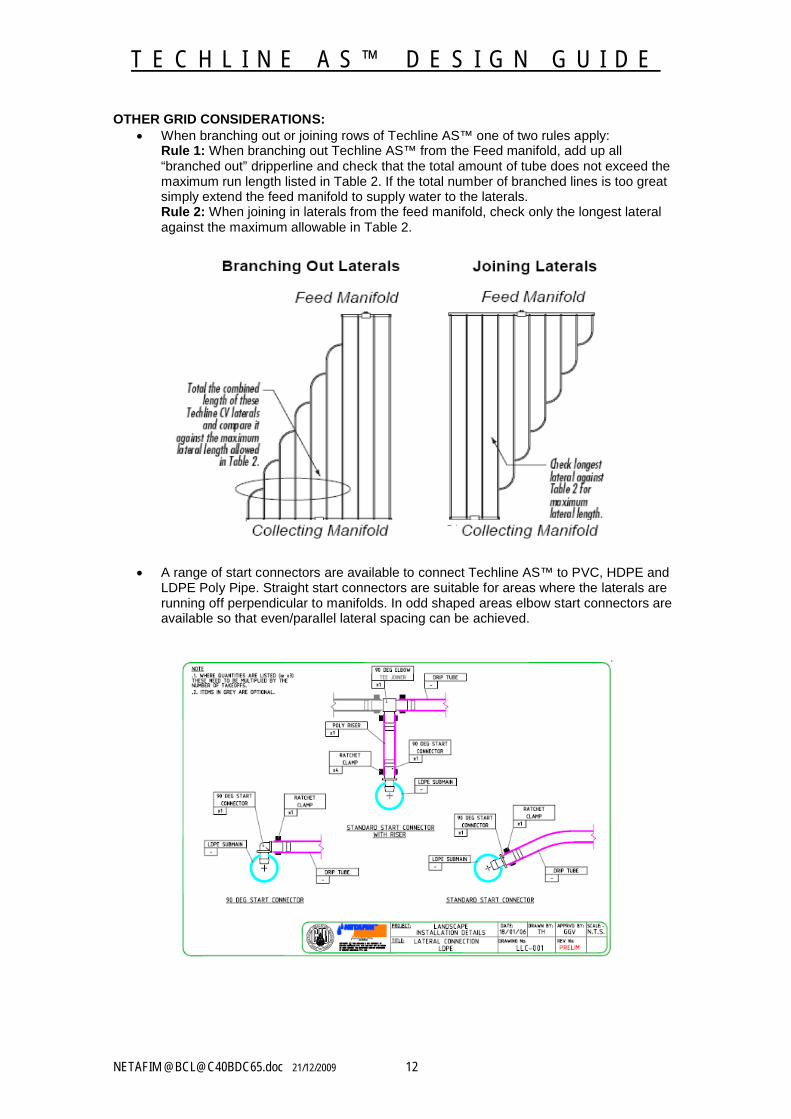
OTHER GRID CONSIDERATIONS: When branching out or joining rows of Techline AS™ one of two rules apply:
Rule 1: When branching out Techline AS™ from the Feed manifold, add up all “branched out” dripperline and check that the total amount of tube does not exceed the maximum run length listed in Table 2. If the total number of branched lines is too great simply extend the feed manifold to supply water to the laterals. Rule 2: When joining in laterals from the feed manifold, check only the longest lateral against the maximum allowable in Table 2.
A range of start connectors are available to connect Techline AS™ to PVC, HDPE and LDPE Poly Pipe. Straight start connectors are suitable for areas where the laterals are running off perpendicular to manifolds. In odd shaped areas elbow start connectors are available so that even/parallel lateral spacing can be achieved.
T E C H L I N E A S ™ D E S I G N G U I D E
NETAFIM @[email protected] 21/12/2009 13
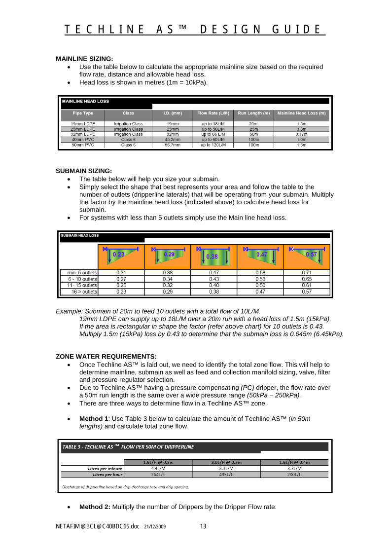
MAINLINE SIZING: Use the table below to calculate the appropriate mainline size based on the required
flow rate, distance and allowable head loss. Head loss is shown in metres (1m = 10kPa).
SUBMAIN SIZING: The table below will help you size your submain. Simply select the shape that best represents your area and follow the table to the
number of outlets (dripperline laterals) that will be operating from your submain. Multiply the factor by the mainline head loss (indicated above) to calculate head loss for submain.
For systems with less than 5 outlets simply use the Main line head loss.
Example: Submain of 20m to feed 10 outlets with a total flow of 10L/M.19mm LDPE can supply up to 18L/M over a 20m run with a head loss of 1.5m (15kPa).If the area is rectangular in shape the factor (refer above chart) for 10 outlets is 0.43. Multiply 1.5m (15kPa) loss by 0.43 to determine that the submain loss is 0.645m (6.45kPa).
ZONE WATER REQUIREMENTS: Once Techline AS™ is laid out, we need to identify the total zone flow. This will help to
determine mainline, submain as well as feed and collection manifold sizing, valve, filter and pressure regulator selection.
Due to Techline AS™ having a pressure compensating (PC) dripper, the flow rate over a 50m run length is the same over a wide pressure range (50kPa – 250kPa).
There are three ways to determine flow in a Techline AS™ zone.
Method 1: Use Table 3 below to calculate the amount of Techline AS™ (in 50m lengths) and calculate total zone flow.
Method 2: Multiply the number of Drippers by the Dripper Flow rate.
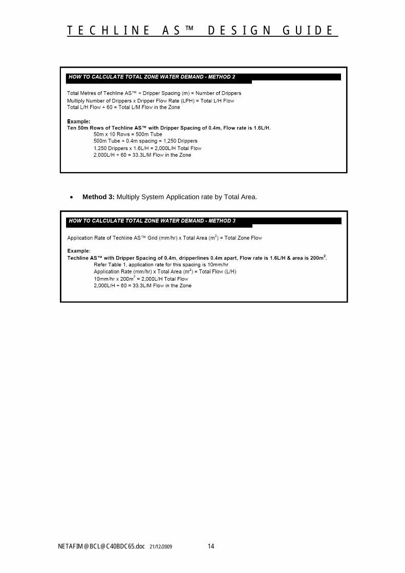
T E C H L I N E A S ™ D E S I G N G U I D E
NETAFIM @[email protected] 21/12/2009 14
Method 3: Multiply System Application rate by Total Area.
T E C H L I N E A S ™ D E S I G N G U I D E
NETAFIM @[email protected] 21/12/2009 15
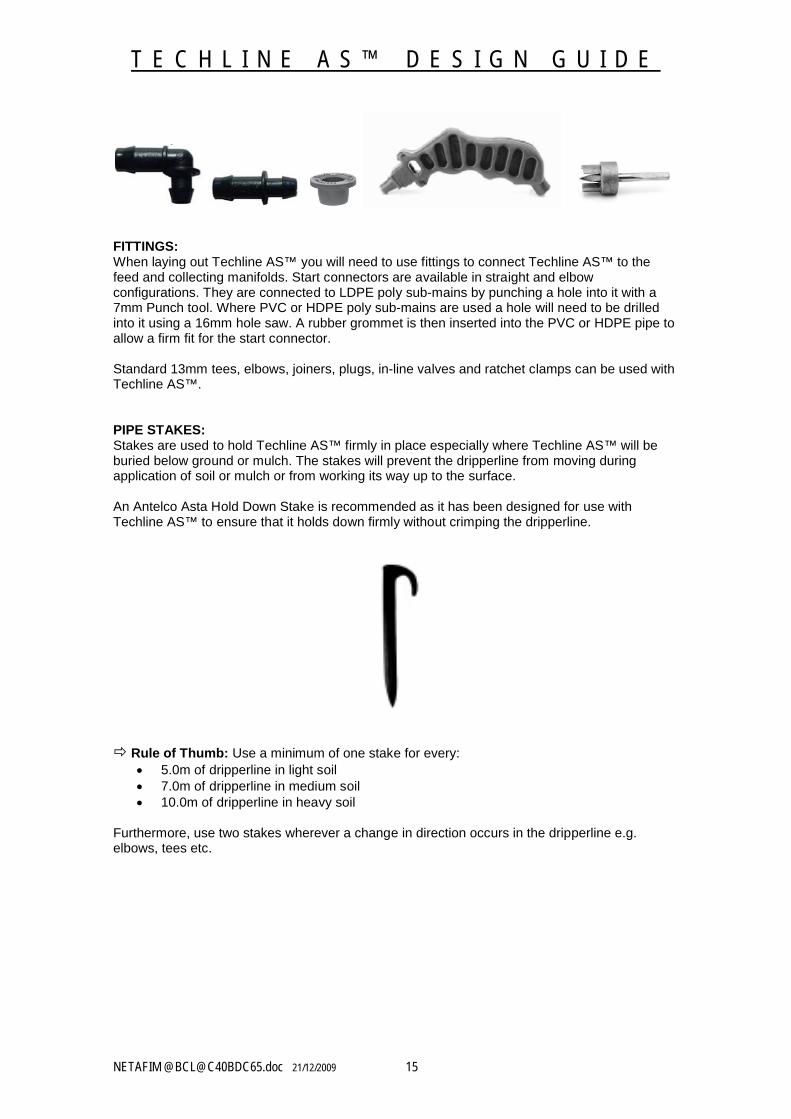
FITTINGS:When laying out Techline AS™ you will need to use fittings to connect Techline AS™ to the feed and collecting manifolds. Start connectors are available in straight and elbow configurations. They are connected to LDPE poly sub-mains by punching a hole into it with a 7mm Punch tool. Where PVC or HDPE poly sub-mains are used a hole will need to be drilled into it using a 16mm hole saw. A rubber grommet is then inserted into the PVC or HDPE pipe to allow a firm fit for the start connector.
Standard 13mm tees, elbows, joiners, plugs, in-line valves and ratchet clamps can be used with Techline AS™.
PIPE STAKES:Stakes are used to hold Techline AS™ firmly in place especially where Techline AS™ will be buried below ground or mulch. The stakes will prevent the dripperline from moving during application of soil or mulch or from working its way up to the surface.
An Antelco Asta Hold Down Stake is recommended as it has been designed for use with Techline AS™ to ensure that it holds down firmly without crimping the dripperline.
Rule of Thumb: Use a minimum of one stake for every: 5.0m of dripperline in light soil 7.0m of dripperline in medium soil 10.0m of dripperline in heavy soil
Furthermore, use two stakes wherever a change in direction occurs in the dripperline e.g. elbows, tees etc.
T E C H L I N E A S ™ D E S I G N G U I D E
NETAFIM @[email protected] 21/12/2009 16
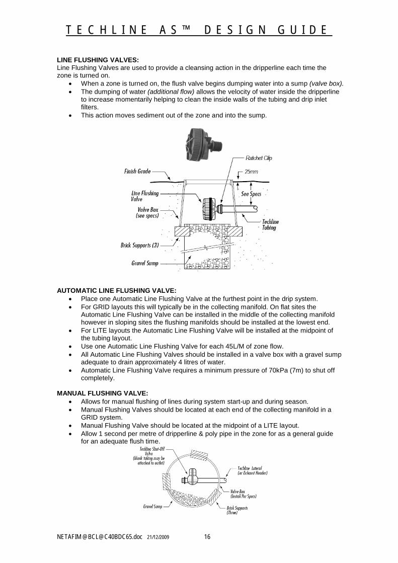
LINE FLUSHING VALVES:Line Flushing Valves are used to provide a cleansing action in the dripperline each time the zone is turned on.
When a zone is turned on, the flush valve begins dumping water into a sump (valve box). The dumping of water (additional flow) allows the velocity of water inside the dripperline
to increase momentarily helping to clean the inside walls of the tubing and drip inlet filters.
This action moves sediment out of the zone and into the sump.
AUTOMATIC LINE FLUSHING VALVE: Place one Automatic Line Flushing Valve at the furthest point in the drip system. For GRID layouts this will typically be in the collecting manifold. On flat sites the
Automatic Line Flushing Valve can be installed in the middle of the collecting manifold however in sloping sites the flushing manifolds should be installed at the lowest end.
For LITE layouts the Automatic Line Flushing Valve will be installed at the midpoint of the tubing layout.
Use one Automatic Line Flushing Valve for each 45L/M of zone flow. All Automatic Line Flushing Valves should be installed in a valve box with a gravel sump
adequate to drain approximately 4 litres of water. Automatic Line Flushing Valve requires a minimum pressure of 70kPa (7m) to shut off
completely.
MANUAL FLUSHING VALVE: Allows for manual flushing of lines during system start-up and during season. Manual Flushing Valves should be located at each end of the collecting manifold in a
GRID system. Manual Flushing Valve should be located at the midpoint of a LITE layout. Allow 1 second per metre of dripperline & poly pipe in the zone for as a general guide
for an adequate flush time.
T E C H L I N E A S ™ D E S I G N G U I D E
NETAFIM @[email protected] 21/12/2009 17
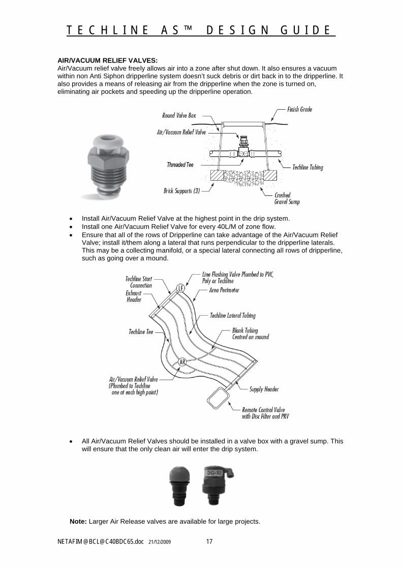
AIR/VACUUM RELIEF VALVES:Air/Vacuum relief valve freely allows air into a zone after shut down. It also ensures a vacuum within non Anti Siphon dripperline system doesn’t suck debris or dirt back in to the dripperline. It also provides a means of releasing air from the dripperline when the zone is turned on, eliminating air pockets and speeding up the dripperline operation.
Install Air/Vacuum Relief Valve at the highest point in the drip system. Install one Air/Vacuum Relief Valve for every 40L/M of zone flow. Ensure that all of the rows of Dripperline can take advantage of the Air/Vacuum Relief
Valve; install it/them along a lateral that runs perpendicular to the dripperline laterals. This may be a collecting manifold, or a special lateral connecting all rows of dripperline, such as going over a mound.
All Air/Vacuum Relief Valves should be installed in a valve box with a gravel sump. This will ensure that the only clean air will enter the drip system.
Note: Larger Air Release valves are available for large projects.
T E C H L I N E A S ™ D E S I G N G U I D E
NETAFIM @[email protected] 21/12/2009 18
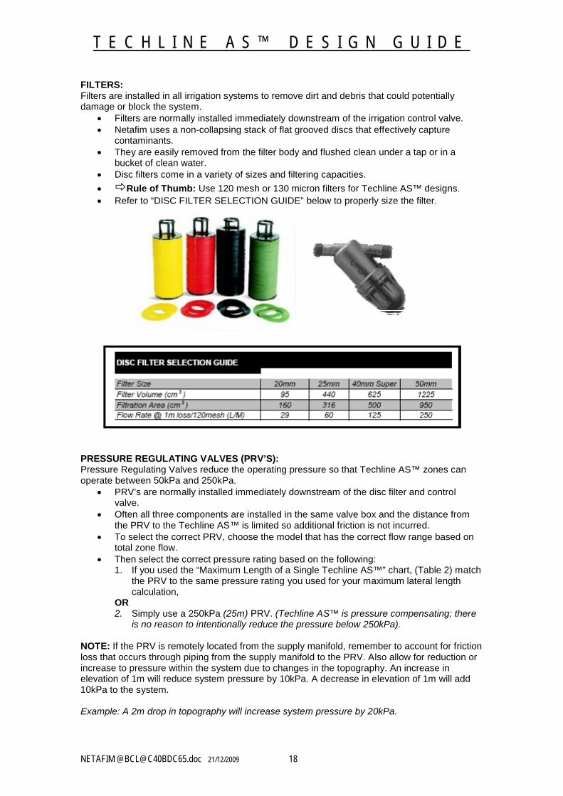
FILTERS:Filters are installed in all irrigation systems to remove dirt and debris that could potentially damage or block the system.
Filters are normally installed immediately downstream of the irrigation control valve. Netafim uses a non-collapsing stack of flat grooved discs that effectively capture
contaminants. They are easily removed from the filter body and flushed clean under a tap or in a
bucket of clean water. Disc filters come in a variety of sizes and filtering capacities.
Rule of Thumb: Use 120 mesh or 130 micron filters for Techline AS™ designs. Refer to “DISC FILTER SELECTION GUIDE” below to properly size the filter.
PRESSURE REGULATING VALVES (PRV’S):Pressure Regulating Valves reduce the operating pressure so that Techline AS™ zones can operate between 50kPa and 250kPa.
PRV’s are normally installed immediately downstream of the disc filter and control valve.
Often all three components are installed in the same valve box and the distance from the PRV to the Techline AS™ is limited so additional friction is not incurred.
To select the correct PRV, choose the model that has the correct flow range based on total zone flow.
Then select the correct pressure rating based on the following:1. If you used the “Maximum Length of a Single Techline AS™” chart, (Table 2) match
the PRV to the same pressure rating you used for your maximum lateral length calculation,
OR2. Simply use a 250kPa (25m) PRV. (Techline AS™ is pressure compensating; there
is no reason to intentionally reduce the pressure below 250kPa).
NOTE: If the PRV is remotely located from the supply manifold, remember to account for friction loss that occurs through piping from the supply manifold to the PRV. Also allow for reduction or increase to pressure within the system due to changes in the topography. An increase in elevation of 1m will reduce system pressure by 10kPa. A decrease in elevation of 1m will add 10kPa to the system.
Example: A 2m drop in topography will increase system pressure by 20kPa.
T E C H L I N E A S ™ D E S I G N G U I D E
NETAFIM @[email protected] 21/12/2009 19
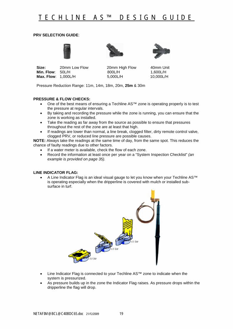
PRV SELECTION GUIDE:
Size: 20mm Low Flow 20mm High Flow 40mm Unit Min. Flow: 50L/H 800L/H 1,600L/H Max. Flow: 1,000L/H 5,000L/H 10,000L/H
Pressure Reduction Range: 11m, 14m, 18m, 20m, 25m & 30m
PRESSURE & FLOW CHECKS: One of the best means of ensuring a Techline AS™ zone is operating properly is to test
the pressure at regular intervals. By taking and recording the pressure while the zone is running, you can ensure that the
zone is working as installed. Take the reading as far away from the source as possible to ensure that pressures
throughout the rest of the zone are at least that high. If readings are lower than normal, a line break, clogged filter, dirty remote control valve,
clogged PRV, or reduced line pressure are possible causes.NOTE: Always take the readings at the same time of day, from the same spot. This reduces the chance of faulty readings due to other factors.
If a water meter is available, check the flow of each zone. Record the information at least once per year on a “System Inspection Checklist” (an
example is provided on page 35).
LINE INDICATOR FLAG: A Line Indicator Flag is an ideal visual gauge to let you know when your Techline AS™
is operating especially when the dripperline is covered with mulch or installed sub-surface in turf.
Line Indicator Flag is connected to your Techline AS™ zone to indicate when the system is pressurized.
As pressure builds up in the zone the Indicator Flag raises. As pressure drops within the dripperline the flag will drop.
T E C H L I N E A S ™ D E S I G N G U I D E
NETAFIM @[email protected] 21/12/2009 20
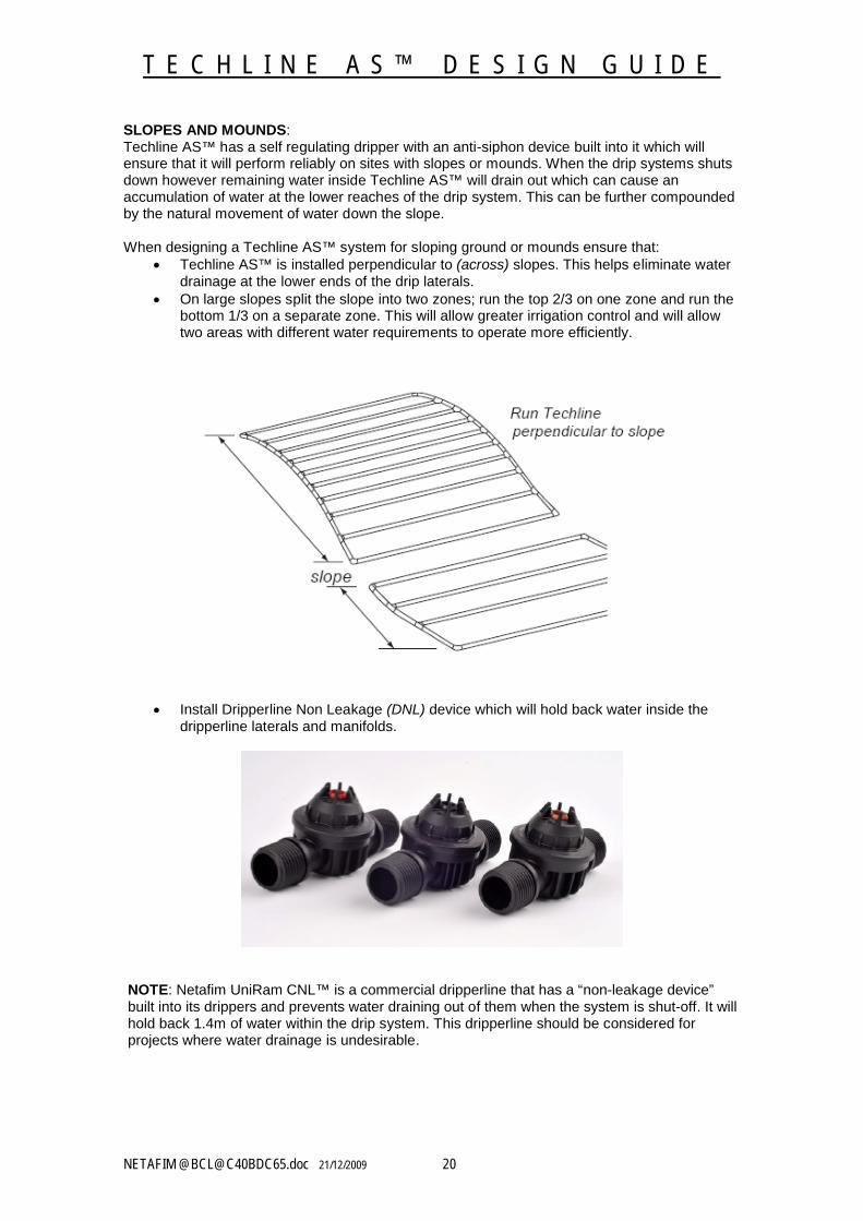
SLOPES AND MOUNDS:Techline AS™ has a self regulating dripper with an anti-siphon device built into it which will ensure that it will perform reliably on sites with slopes or mounds. When the drip systems shuts down however remaining water inside Techline AS™ will drain out which can cause an accumulation of water at the lower reaches of the drip system. This can be further compoundedby the natural movement of water down the slope.
When designing a Techline AS™ system for sloping ground or mounds ensure that: Techline AS™ is installed perpendicular to (across) slopes. This helps eliminate water
drainage at the lower ends of the drip laterals. On large slopes split the slope into two zones; run the top 2/3 on one zone and run the
bottom 1/3 on a separate zone. This will allow greater irrigation control and will allow two areas with different water requirements to operate more efficiently.
Install Dripperline Non Leakage (DNL) device which will hold back water inside the dripperline laterals and manifolds.
NOTE: Netafim UniRam CNL™ is a commercial dripperline that has a “non-leakage device” built into its drippers and prevents water draining out of them when the system is shut-off. It will hold back 1.4m of water within the drip system. This dripperline should be considered for projects where water drainage is undesirable.

T E C H L I N E A S ™ D E S I G N G U I D E
NETAFIM @[email protected] 21/12/2009 21
TECHLINE AS™ IN TURF (SDI): Refer to Table 1 for correct drip discharge, drip and dripperline spacing. Refer to Table 1 for correct Techline AS™ burial depth. Ensure that all dripperlines are installed at a uniform spacing and at an even depth.
Any variations may cause a variation in water application rates. Always use the GRID layout for SDI systems. Techline AS™ can be laid on top of a level surface and have topsoil applied to it at a
uniform depth. Techline AS™ can also be inserted into the ground with a plough. Again ensure that it
is installed at a uniform depth. Install a Techfilter to protect the system from root intrusion.
TECHLINE AS™ IN NEW SODDED TURF: Follow Table 1 General Guideline’s recommendations for turf. Bury the Techline AS™ to the depth specified in Table 1 ensuring that it is laid at an
even depth. In areas where mechanical aeration will be used, bury the Techline AS™ 150mm below
final grade and ensure that aeration does not exceed 100m in depth. When installing the sod:
o It is important that the final grade is smooth, ensuring that the sod makes solid contact with the soil.
o Properly “knit” the edges together o Roll the sod to ensure good contact.
If the irrigation system is automatic:o Set the zone to operate several times per day (check local water restrictions)o Provide additional overhead irrigation until roots establish
Once you can not pull the edges of the sod up, discontinue overhead watering. Irrigate on a daily or every-other-day basis (check local water restrictions)
NOTE: Temporary overhead irrigation may be required to irrigate sods/turf for the first 7-10 days until root establishment occurs and SDI becomes effective.
TECHLINE AS™ ABOVE AND BELOW GRADE:Techline AS™ is designed to be used in a variety of ways:
o It can be laid on the surface (it’s UV resistant) and held in place with Asta Hold DownStakes.
o It can be laid on the surface, staked into place and covered with mulch, oro It can be buried below grade.
NOTE: When using Techline AS™ above grade with stakes, use enough stakes to firmly hold the dripperline in place.
T E C H L I N E A S ™ D E S I G N G U I D E
NETAFIM @[email protected] 21/12/2009 22
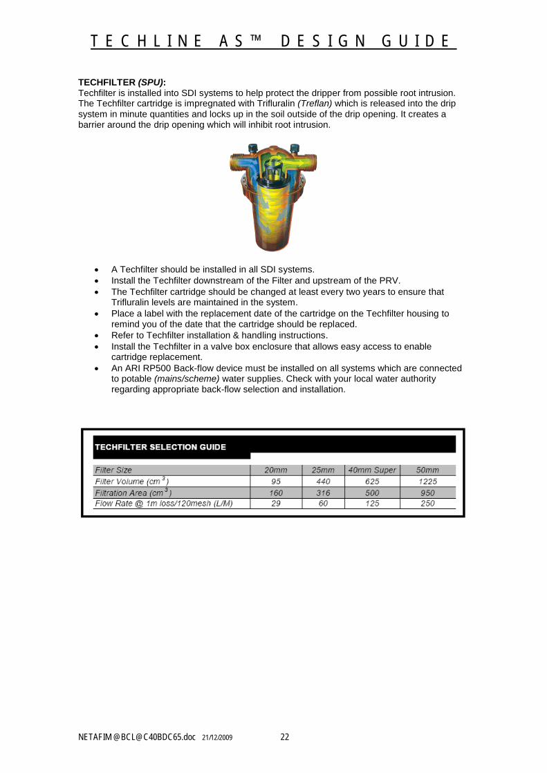
TECHFILTER (SPU):Techfilter is installed into SDI systems to help protect the dripper from possible root intrusion. The Techfilter cartridge is impregnated with Trifluralin (Treflan) which is released into the drip system in minute quantities and locks up in the soil outside of the drip opening. It creates a barrier around the drip opening which will inhibit root intrusion.
A Techfilter should be installed in all SDI systems. Install the Techfilter downstream of the Filter and upstream of the PRV. The Techfilter cartridge should be changed at least every two years to ensure that
Trifluralin levels are maintained in the system. Place a label with the replacement date of the cartridge on the Techfilter housing to
remind you of the date that the cartridge should be replaced. Refer to Techfilter installation & handling instructions. Install the Techfilter in a valve box enclosure that allows easy access to enable
cartridge replacement. An ARI RP500 Back-flow device must be installed on all systems which are connected
to potable (mains/scheme) water supplies. Check with your local water authorityregarding appropriate back-flow selection and installation.
T E C H L I N E A S ™ D E S I G N G U I D E
NETAFIM @[email protected] 21/12/2009 23
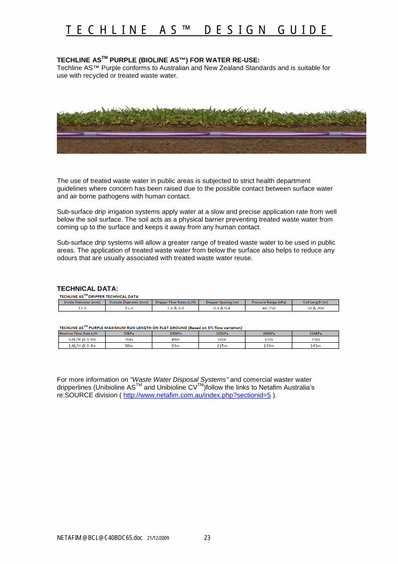
TECHLINE ASTM PURPLE (BIOLINE AS™) FOR WATER RE-USE:Techline AS™ Purple conforms to Australian and New Zealand Standards and is suitable for use with recycled or treated waste water.
The use of treated waste water in public areas is subjected to strict health department guidelines where concern has been raised due to the possible contact between surface water and air borne pathogens with human contact.
Sub-surface drip irrigation systems apply water at a slow and precise application rate from well below the soil surface. The soil acts as a physical barrier preventing treated waste water from coming up to the surface and keeps it away from any human contact.
Sub-surface drip systems will allow a greater range of treated waste water to be used in public areas. The application of treated waste water from below the surface also helps to reduce any odours that are usually associated with treated waste water reuse.
TECHNICAL DATA:
For more information on “Waste Water Disposal Systems” and comercial waster water dripperlines (Unibioline ASTM and Unibioline CVTM)follow the links to Netafim Australia’s re:SOURCE division ( http://www.netafim.com.au/index.php?sectionid=5 ).
T E C H L I N E A S ™ D E S I G N G U I D E
NETAFIM @[email protected] 21/12/2009 24
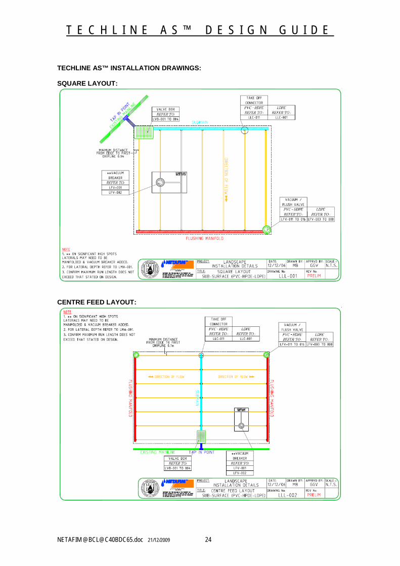
TECHLINE AS™ INSTALLATION DRAWINGS:
SQUARE LAYOUT:
CENTRE FEED LAYOUT:
T E C H L I N E A S ™ D E S I G N G U I D E
NETAFIM @[email protected] 21/12/2009 25
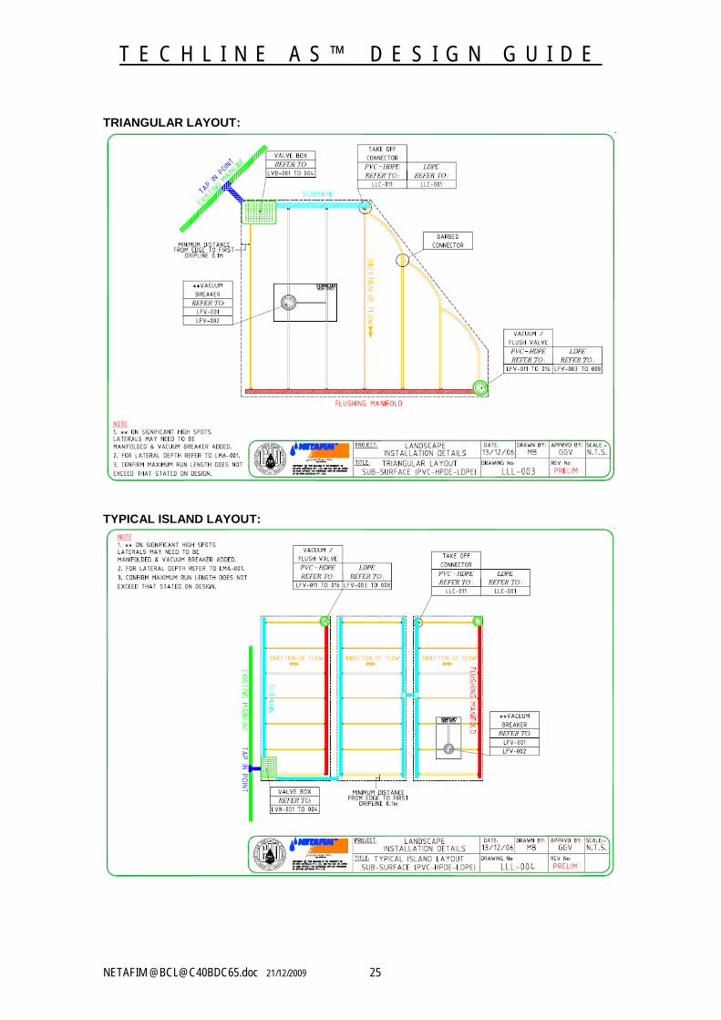
TRIANGULAR LAYOUT:
TYPICAL ISLAND LAYOUT:
T E C H L I N E A S ™ D E S I G N G U I D E
NETAFIM @[email protected] 21/12/2009 26
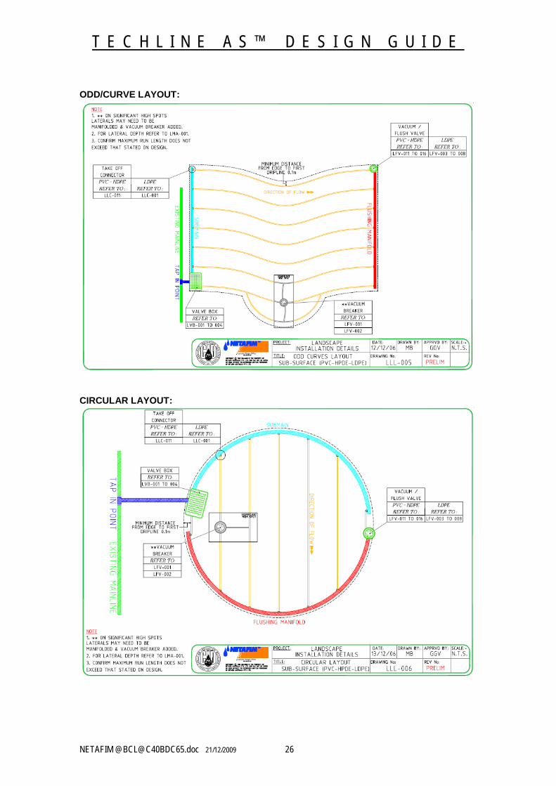
ODD/CURVE LAYOUT:
CIRCULAR LAYOUT:
T E C H L I N E A S ™ D E S I G N G U I D E
NETAFIM @[email protected] 21/12/2009 27
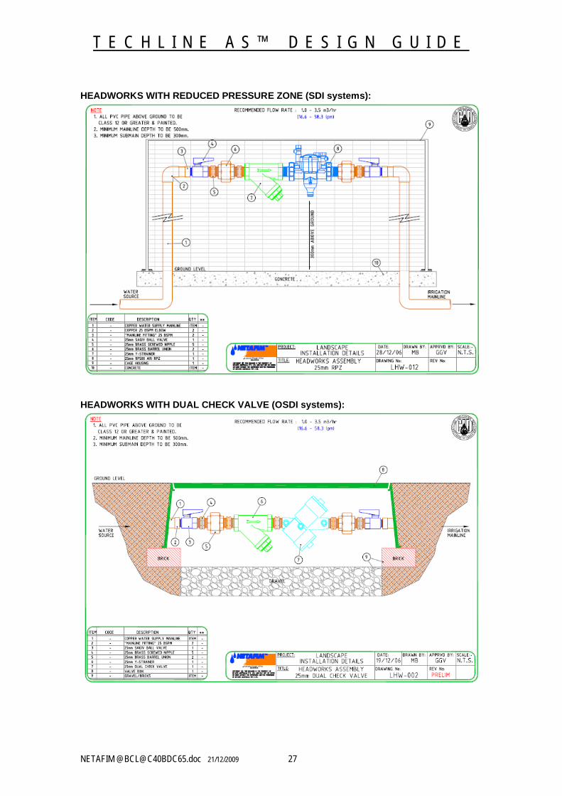
HEADWORKS WITH REDUCED PRESSURE ZONE (SDI systems):
HEADWORKS WITH DUAL CHECK VALVE (OSDI systems):
T E C H L I N E A S ™ D E S I G N G U I D E
NETAFIM @[email protected] 21/12/2009 28
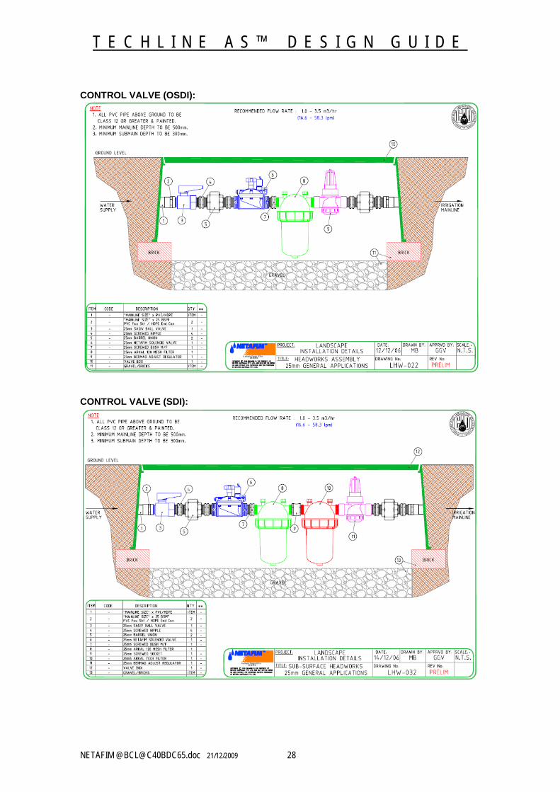
CONTROL VALVE (OSDI):
CONTROL VALVE (SDI):
T E C H L I N E A S ™ D E S I G N G U I D E
NETAFIM @[email protected] 21/12/2009 29
TECHLINE AS™ DESIGN FORMULAS:
FORMULA 1.1 ESTIMATED TOTAL LENGTH OF DRIPPLERLINE
Irrigated Area (m2) .
Minimum Recommended Lateral Spacing (m)
In which:Estimated Total Length of Dripperline = Total Metres of Dripperline in a ZoneIrrigated Area = Total Area in Square MetresMinimum Recommended Lateral (Row) Spacing = The Minimum Row Spacing in Table 1.
Example: Area 200m2 and Minimum Recommended Lateral Spacing of 0.5m.
200m2 = 400m0.5m
Total Length of Dripperline is 400m.
FORMULA 1.2 APPLICATION RATE (mm/Hr)
Drip Discharge Rate (L/H) .Dripper Spacing (m) x Dripperline Row Spacing (m)
In which:Application Rate is = mm per Hour of Water Being AppliedDripper Flow Rate = Litres per Hour Flow of One DripperDripper Spacing = Spacing in Metres of Drippers Inside TubingDripperline Row Spacing = Metres Between Techline AS™ Laterals (Rows)
Example: Drip Discharge Rate of 1.6L/H, Drip Spacing of 0.4m and Dripperline Row Spacing of 0.5m.
1.6L/H . = 1.6L/H = 8.0mm/Hr 0.4m x 0.5m 0.2m2
Application Rate is 8.0mm/Hr per square meter of area irrigated.
FORMULA 1.3 NUMBER OF DRIPPERS IN A ZONE
Total Dripperline (m) Dripper Spacing (m)
In which:Number of Drippers = Total Number of DrippersTotal Dripperline = Length of all Dripperline in a Zone in MetresDripper Spacing = Spacing in Metres of Drippers Inside Tubing
Example: Total Dripperline of 400m and Dripper Spacing of 0.4m.
400m = 1,000 Drippers0.4m
Total number of drippers in this zone is 1,000 drippers.
T E C H L I N E A S ™ D E S I G N G U I D E
NETAFIM @[email protected] 21/12/2009 30
FORMULA 1.4 FLOW PER ZONE
Number of Drippers x Dripper Flow Rate (L/H) = Total Flow (L/H)
In which:Flow per Zone = Total Litres per HourNumber of Drippers = Total Number of DrippersDripper Flow Rate = Litres per Hour of one DripperL/H = Litres per Hour of Flow of One Dripper
Example: 1,000 Drippers in a zone with a discharge rate of 1.6L/H
1,000 Drippers x 1.6L/H = 1,600L/H 1,600L/H ÷ 60 (convert to L/M) = 26.7L/M
Total Flow for this zone is 26.L/M.
FORMULA 1.5 ESTIMATED TOTAL ZONE FLOW
Application Rate of System (mm/Hr) x Irrigated Area (m2) = Total Zone Flow (L/H)
In which:Application Rate = mm per Hour of Water Being Applied Irrigated Area = Total Area in Square MetresTotal Zone Flow = Total Litres per Hour in the Irrigated Zone
Example: Application Rate of 8.0mm/Hr in an irrigated area of 200m2
8.0mm/Hr x 200m2 = 1,600L/H (÷ 60 to convert to L/M) = 26.7L/M
Total Zone Flow for this area is 26.7L/M.
T E C H L I N E A S ™ D E S I G N G U I D E
NETAFIM @[email protected] 21/12/2009 31
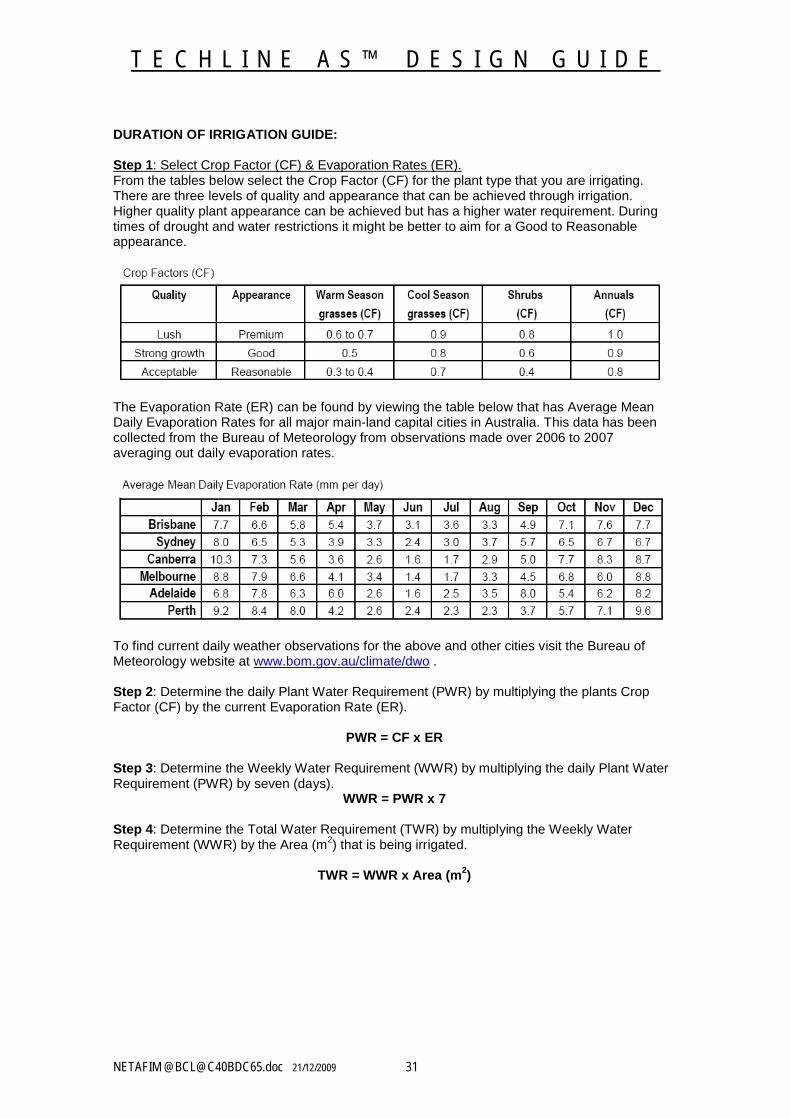
DURATION OF IRRIGATION GUIDE:
Step 1: Select Crop Factor (CF) & Evaporation Rates (ER).From the tables below select the Crop Factor (CF) for the plant type that you are irrigating. There are three levels of quality and appearance that can be achieved through irrigation. Higher quality plant appearance can be achieved but has a higher water requirement. During times of drought and water restrictions it might be better to aim for a Good to Reasonable appearance.
The Evaporation Rate (ER) can be found by viewing the table below that has Average Mean Daily Evaporation Rates for all major main-land capital cities in Australia. This data has been collected from the Bureau of Meteorology from observations made over 2006 to 2007 averaging out daily evaporation rates.
To find current daily weather observations for the above and other cities visit the Bureau of Meteorology website at www.bom.gov.au/climate/dwo .
Step 2: Determine the daily Plant Water Requirement (PWR) by multiplying the plants Crop Factor (CF) by the current Evaporation Rate (ER).
PWR = CF x ER
Step 3: Determine the Weekly Water Requirement (WWR) by multiplying the daily Plant Water Requirement (PWR) by seven (days).
WWR = PWR x 7
Step 4: Determine the Total Water Requirement (TWR) by multiplying the Weekly Water Requirement (WWR) by the Area (m2) that is being irrigated.
TWR = WWR x Area (m2)
T E C H L I N E A S ™ D E S I G N G U I D E
NETAFIM @[email protected] 21/12/2009 32
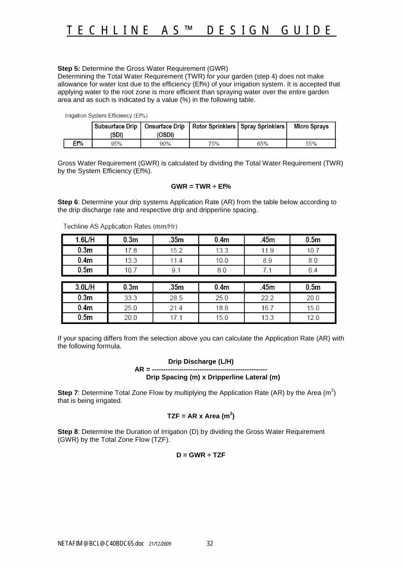
Step 5: Determine the Gross Water Requirement (GWR) Determining the Total Water Requirement (TWR) for your garden (step 4) does not make allowance for water lost due to the efficiency (Ef%) of your irrigation system. It is accepted that applying water to the root zone is more efficient than spraying water over the entire garden area and as such is indicated by a value (%) in the following table.
Gross Water Requirement (GWR) is calculated by dividing the Total Water Requirement (TWR) by the System Efficiency (Ef%).
GWR = TWR ÷ Ef%
Step 6: Determine your drip systems Application Rate (AR) from the table below according to the drip discharge rate and respective drip and dripperline spacing.
If your spacing differs from the selection above you can calculate the Application Rate (AR) with the following formula.
Drip Discharge (L/H)AR = ---------------------------------------------------
Drip Spacing (m) x Dripperline Lateral (m)
Step 7: Determine Total Zone Flow by multiplying the Application Rate (AR) by the Area (m2) that is being irrigated.
TZF = AR x Area (m2)
Step 8: Determine the Duration of Irrigation (D) by dividing the Gross Water Requirement (GWR) by the Total Zone Flow (TZF).
D = GWR ÷ TZF
T E C H L I N E A S ™ D E S I G N G U I D E
NETAFIM @[email protected] 21/12/2009 33
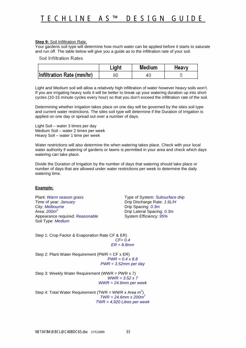
Step 9: Soil Infiltration Rate.Your gardens soil type will determine how much water can be applied before it starts to saturate and run off. The table below will give you a guide as to the infiltration rate of your soil.
Light and Medium soil will allow a relatively high infiltration of water however heavy soils won’t. If you are irrigating heavy soils it will be better to break up your watering duration up into short cycles (10-15 minute cycles every hour) so that you don’t exceed the infiltration rate of the soil.
Determining whether irrigation takes place on one day will be governed by the sites soil type and current water restrictions. The sites soil type will determine if the Duration of Irrigation is applied on one day or spread out over a number of days.
Light Soil – water 3 times per dayMedium Soil – water 2 times per weekHeavy Soil – water 1 time per week
Water restrictions will also determine the when watering takes place. Check with your local water authority if watering of gardens or lawns is permitted in your area and check which days watering can take place.
Divide the Duration of Irrigation by the number of days that watering should take place or number of days that are allowed under water restrictions per week to determine the daily watering time.
Example:
Plant: Warm season grass Type of System: Subsurface dripTime of year: January Drip Discharge Rate: 1.6L/HCity: Melbourne Drip Spacing: 0.3mArea: 200m2 Drip Lateral Spacing: 0.3mAppearance required: Reasonable System Efficiency: 95%Soil Type: Medium
Step 1: Crop Factor & Evaporation Rate CF & ER)CF= 0.4
ER = 8.8mm
Step 2: Plant Water Requirement (PWR = CF x ER)PWR = 0.4 x 8.8
PWR = 3.52mm per day
Step 3: Weekly Water Requirement (WWR = PWR x 7)WWR = 3.52 x 7
WWR = 24.6mm per week
Step 4: Total Water Requirement (TWR = WWR x Area m2)TWR = 24.6mm x 200m2
TWR = 4,920 Litres per week

T E C H L I N E A S ™ D E S I G N G U I D E
NETAFIM @[email protected] 21/12/2009 34
Step 5: Gross Water Requirement (GWR = TWR ÷ Ef%)GWR = 4,920 ÷ 95%
GWR = 5,178 Litres per week
Step 6: Application Rate(AR)Refer AR Table – 1.6L/H x 0.3m x0.3m
AR = 17.8mm/Hr
Step 7: Total Zone Flow (TZF = AR x Area m2)TZF = 17.8mm x 200m2
TZF = 3560 Litres per hour
Step 8: Duration of Irrigation (D = GWR ÷ TZF)D = 5,178L ÷ 3560L
D = 1.45 Hrs per week(1.45Hrs x 60 = 87 minutes per week)
Step 9: Soil Infiltration RateSoil Type - MediumInfiltration rate – 40mm/HrMedium Soil – 2 waterings per week (or current watering restrictions)
Duration of Irrigation for this site is 87 minutes and the application rate of the system is 17.8mm/Hr. Medium soil has an infiltration rate of 40mm/Hr so wont require any pulse irrigating.
Note: If the sites soil was heavy pulsing would be required ( approx. 6 x 15 minute cycles).
Divide the Duration of Irrigation (87 minutes) by the number of days watering should/can take place (2 days) to determine the duration of irrigation per day.
87 minutes ÷ 2 days = 43.5 minutes each irrigation day
These steps are designed to serve as a guide only when determining watering regimes. Other influences may also affect water requirements such as micro climates, wind etc. Always perform visual checks to ensure your plants are getting enough water.
Netafim Watering Calculator:A Netafim Water Calculator can be downloaded from the Landscape section ( http://www.netafim.com.au/index.php?sectionid=3 )of the Netafim Australia website.
The calculator allows you to select relevant data from a range of pop up windows to simply and quickly determine watering times according to your drip systems output, plant type and current weather conditions.

T E C H L I N E A S ™ D E S I G N G U I D E
NETAFIM @[email protected] 21/12/2009 35
TECHLINE AS™ INSTALLATION GUIDE:
Specifications: The information in this guide should be used when installing drip irrigation system in conjunction with specific design details that are usually supplied on a Drip Irrigation Design/Plan. Specifications on the irrigation design/plan will always take precedent over the information in this guide.
Drip Irrigation System Specification1.0 Solenoid ValveSolenoid valve is to be installed to the main-line and housed in a lockable valve box (at least 250mm in diameter) that shall have sufficient room to access and maintain the valve. All wiring into the valve enclosure shall be looped to allow for expansion and contraction and servicing.Only one valve per valve box unless otherwise agreed with the site supervisor. All valve boxes shall be supported by bricks to ensure that the valve box does not come in direct contact with the pipe work. Place gravel to a depth of 50mm in the bottom of the valve enclosure.
2.0 FiltersArkal disc filter with a mesh size of 120 mesh (130 micron) shall be installed on all dripperlines either immediately downstream of the solenoid valve or at the head works. Ensure that the filter is fully installed prior to the flushing of any dripperlines or sub-mains. Filter shall be accessible for servicing and installed in an appropriately sized valve box which shall be free of any dirt or debris. Place gravel to a depth of 50mm in the bottom of the valve enclosure.
3.0 TechfilterTech-filter is required wherever the dripperline is buried directly into the soil (SDI) and installed immediately downstream of the filter. Ensure that the Techfilter is installed prior to the installation of any dripperline. Tech-filter shall be accessible for servicing and installed in an appropriately sized valve box which shall be free of any dirt or debris. Place gravel to a depth of 50mm in the bottom of the valve enclosure. Also ensure that the appropriate back-flow device (ARI RPZ) is used whenever a Tech-filter is used. Record the date that the Techfilter cartridge should be changed (normally every two (2) years) and fix this to the Techfilter body.
4.0 Pressure Reducing ValvePressure reducing valve is to be installed downstream of the Filter (or in SDI, Tech-filter). Ensure that the pressure reducing valve is accessible for adjustment and servicing purposes and housed in an appropriately sized valve box which shall be free of dirt or debris. Place gravel to a depth of 50mm in the bottom of the valve enclosure.
5.0 Dripperline InstallationDripperline will be installed in a grid formation. All lateral lines will be connected to a feed and collecting sub-main. All lateral lines are to be installed ensuring that all laterals are laid uniformly, free of any kinks or restrictions and are staked down at regular intervals.
Unless otherwise specified on the irrigation plan all dripperline is to be installed to the recommendations listed below:
Soil Type Drip Dripperline Min. depth below spacing (mm) spacing (mm) surface (mm)
Light 300 300 15Medium 400 400 100Heavy 500 500 150
T E C H L I N E A S ™ D E S I G N G U I D E
NETAFIM @[email protected] 21/12/2009 36
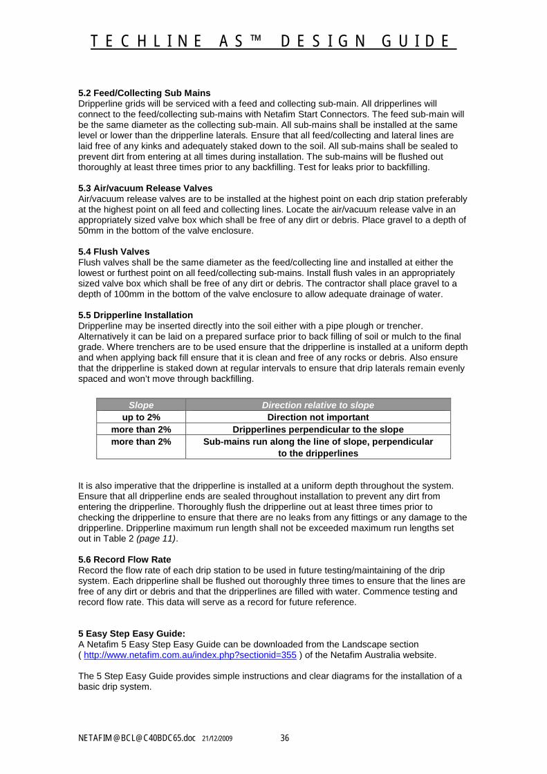
5.2 Feed/Collecting Sub MainsDripperline grids will be serviced with a feed and collecting sub-main. All dripperlines will connect to the feed/collecting sub-mains with Netafim Start Connectors. The feed sub-main will be the same diameter as the collecting sub-main. All sub-mains shall be installed at the same level or lower than the dripperline laterals. Ensure that all feed/collecting and lateral lines are laid free of any kinks and adequately staked down to the soil. All sub-mains shall be sealed to prevent dirt from entering at all times during installation. The sub-mains will be flushed out thoroughly at least three times prior to any backfilling. Test for leaks prior to backfilling.
5.3 Air/vacuum Release ValvesAir/vacuum release valves are to be installed at the highest point on each drip station preferably at the highest point on all feed and collecting lines. Locate the air/vacuum release valve in an appropriately sized valve box which shall be free of any dirt or debris. Place gravel to a depth of 50mm in the bottom of the valve enclosure.
5.4 Flush ValvesFlush valves shall be the same diameter as the feed/collecting line and installed at either the lowest or furthest point on all feed/collecting sub-mains. Install flush vales in an appropriately sized valve box which shall be free of any dirt or debris. The contractor shall place gravel to a depth of 100mm in the bottom of the valve enclosure to allow adequate drainage of water.
5.5 Dripperline InstallationDripperline may be inserted directly into the soil either with a pipe plough or trencher. Alternatively it can be laid on a prepared surface prior to back filling of soil or mulch to the final grade. Where trenchers are to be used ensure that the dripperline is installed at a uniform depth and when applying back fill ensure that it is clean and free of any rocks or debris. Also ensure that the dripperline is staked down at regular intervals to ensure that drip laterals remain evenly spaced and won’t move through backfilling.
It is also imperative that the dripperline is installed at a uniform depth throughout the system. Ensure that all dripperline ends are sealed throughout installation to prevent any dirt from entering the dripperline. Thoroughly flush the dripperline out at least three times prior to checking the dripperline to ensure that there are no leaks from any fittings or any damage to the dripperline. Dripperline maximum run length shall not be exceeded maximum run lengths set out in Table 2 (page 11).
5.6 Record Flow RateRecord the flow rate of each drip station to be used in future testing/maintaining of the drip system. Each dripperline shall be flushed out thoroughly three times to ensure that the lines are free of any dirt or debris and that the dripperlines are filled with water. Commence testing and record flow rate. This data will serve as a record for future reference.
5 Easy Step Easy Guide:A Netafim 5 Easy Step Easy Guide can be downloaded from the Landscape section ( http://www.netafim.com.au/index.php?sectionid=355 ) of the Netafim Australia website.
The 5 Step Easy Guide provides simple instructions and clear diagrams for the installation of a basic drip system.
Slope Direction relative to slopeup to 2% Direction not important
more than 2% Dripperlines perpendicular to the slopemore than 2% Sub-mains run along the line of slope, perpendicular
to the dripperlines
T E C H L I N E A S ™ D E S I G N G U I D E
NETAFIM @[email protected] 21/12/2009 37
6.0 System MaintenanceSystem maintenance shall take place at the start, midway and end of the irrigation season.
6.1 FilterRemove cartridge from filter housing and clean disc cartridge thoroughly. Flush the housing out before replacing filter cartridge and testing.
6.2 TechfilterTechfilter cartridge shall be replaced at least every two years. Take note that the manufacturers’ handling instructions are carefully adhered to when removing and replacing the Techfilter cartridge. Record replacement date of the cartridge and display it on the Techfilter housing.
6.3 Pressure Reducing ValveEnsure that the pressure reducing valve is functioning properly. Test the line pressure at the furthest point of the dripperline to ensure that correct operating pressures are maintained. Adjust the pressure reducing valve accordingly.
6.4 Air/vacuum Release ValvesLocate Air/vacuum release valves and if necessary clean out valve enclosure. Remove Air/vacuum release valve and ensure that the valve is functioning properly. Replace valve and test.
6.5 Flushing the SystemThe drip system should be flushed out thoroughly. Locate flush valves and if necessary clean out valve enclosure. Open all flush valves fully. Commence flush cycle. Flush valves shall be closed off in sequence commencing with those located closest to the solenoid valve and progressively working towards the furthest flush valves on the system.
6.6 DripperlinesOperate station on a manual cycle for approximately 30 minutes. Walk over the irrigated zone and perform a visual check of the drip system. Be vigilant for signs of wetness (leaks/damage to pipe) or dryness (pipe blockages).
6.7 Check Flow RatesRecord the flow rate of each drip station and compare these figures with the flow data collected at installation. Each dripperline shall be flushed out thoroughly three times to ensure that the lines are free of any dirt or debris and that the dripperlines are filled with water. Commence testing and record flow rate.
T E C H L I N E A S ™ D E S I G N G U I D E
NETAFIM @[email protected] 21/12/2009 38
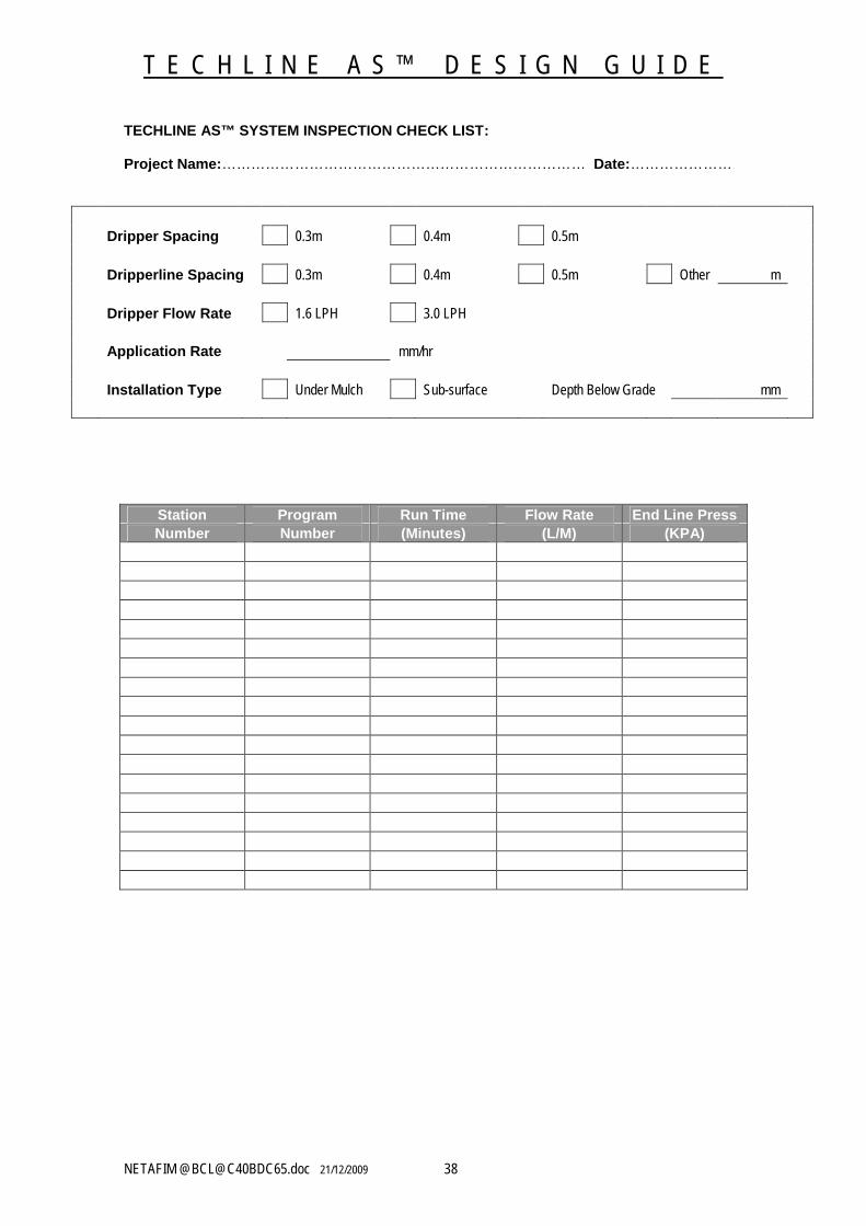
TECHLINE AS™ SYSTEM INSPECTION CHECK LIST:
Project Name:………………………………………………………………… Date:…………………
Dripper Spacing 0.3m 0.4m 0.5m
Dripperline Spacing 0.3m 0.4m 0.5m Other m
Dripper Flow Rate 1.6 LPH 3.0 LPH
Application Rate mm/hr
Installation Type Under Mulch Sub-surface Depth Below Grade mm
Station Program Run Time Flow Rate End Line PressNumber Number (Minutes) (L/M) (KPA)
T E C H L I N E A S ™ D E S I G N G U I D E
NETAFIM @[email protected] 21/12/2009 39
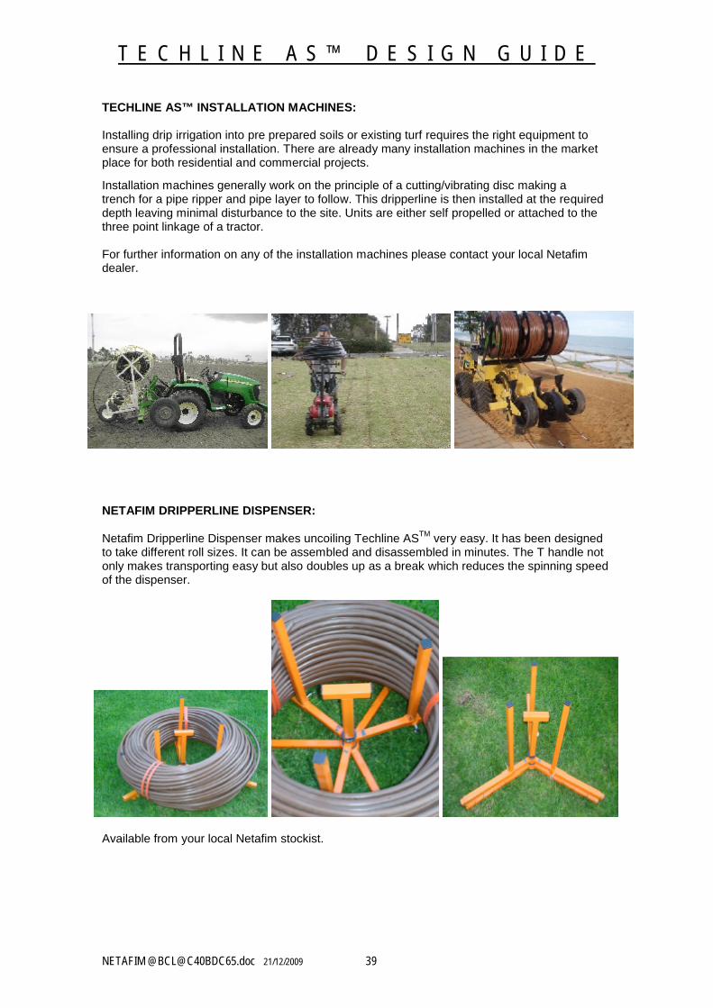
TECHLINE AS™ INSTALLATION MACHINES:
Installing drip irrigation into pre prepared soils or existing turf requires the right equipment to ensure a professional installation. There are already many installation machines in the market place for both residential and commercial projects.
Installation machines generally work on the principle of a cutting/vibrating disc making a trench for a pipe ripper and pipe layer to follow. This dripperline is then installed at the required depth leaving minimal disturbance to the site. Units are either self propelled or attached to the three point linkage of a tractor.
For further information on any of the installation machines please contact your local Netafim dealer.
NETAFIM DRIPPERLINE DISPENSER:
Netafim Dripperline Dispenser makes uncoiling Techline ASTM very easy. It has been designed to take different roll sizes. It can be assembled and disassembled in minutes. The T handle not only makes transporting easy but also doubles up as a break which reduces the spinning speed of the dispenser.
Available from your local Netafim stockist.
T E C H L I N E A S ™ D E S I G N G U I D E
NETAFIM @[email protected] 21/12/2009 40
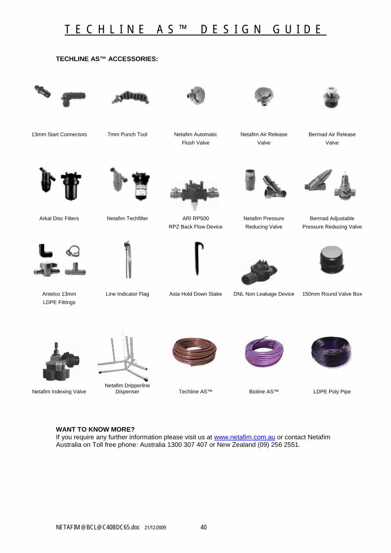
TECHLINE AS™ ACCESSORIES:
13mm Start Connectors 7mm Punch Tool Netafim Automatic Netafim Air Release Bermad Air Release
Flush Valve Valve Valve
Arkal Disc Filters Netafim Techfilter ARI RP500 Netafim Pressure Bermad Adjustable
RPZ Back Flow Device Reducing Valve Pressure Reducing Valve
Antelco 13mm Line Indicator Flag Asta Hold Down Stake DNL Non Leakage Device 150mm Round Valve Box
LDPE Fittings
Netafim Indexing ValveNetafim Dripperline
Dispenser Techline AS™ Bioline AS™ LDPE Poly Pipe
WANT TO KNOW MORE?If you require any further information please visit us at www.netafim.com.au or contact Netafim Australia on Toll free phone: Australia 1300 307 407 or New Zealand (09) 256 2551.