tech manual
DESCRIPTION
allison infoTRANSCRIPT

Printed in the U.S.A. Copyright © 1996 General Motors Corp.
ServiceManual
Allison Transmission
SM1241EN
AUTOMATIC MODELS
AT 540,AT 542(N)(R)(NFE),AT 543,AT 545(N)(R),AT 1542P,AT 1545P(N)
FEBRUARY 1996Revision 1, 1999 April
Division of General Motors CorporationP.O. Box 894 Indianapolis, Indiana 46206-0894

ii Copyright © 1996 General Motors Corp.
ALLISON TRANSMISSION AUTOMATIC AT SERIES TRANSMISSIONS
TRADEMARK USE
The following trademarks are the property of the companies indicated:
•
DEXRON
®
is a registered trademark of General Motors Corporation.
•
Biobor
®
JF is the registered trademark for a biological inhibitor manufactured by U.S. Boraxand Chemical Corporation.
•
Teflon
®
is a registered trademark of the DuPont Corporation.
•
Loctite
®
is a registered trademark of the Loctite Corporation.
NOTE:This publication is revised periodically to include improvements,new models, special tools, and procedures. A revision is indicatedby letter suffix to the publication number. Check with your AllisonTransmission service outlet for the currently applicable publica-tion. Additional copies of this publication may be purchased fromauthorized Allison Transmission service outlets. Look in yourtelephone directory under the heading of Transmissions — Truck,
Tractor, etc.
WARNINGS, CAUTIONS, AND NOTES
Three types of headings are used in this manual to attract your attention:
NOTE:is used when an operating procedure, practice, etc.,is essential to highlight.
WARNING!
is used when an operating procedure, practice,etc., which, if not correctly followed, could resultin personal injury or loss of life.
CAUTION:
is used when an operating procedure, practice,etc., which, if not strictly observed, could resultin damage to or destruction of equipment.
Copyright © 1996 General Motors Corp. iii
IT IS YOUR RESPONSIBILITY to be completely familiar with the Warnings and Cau-tions described in this Service Manual. These Warnings and Cautions advise against theuse of specific service methods that can result in personal injury, damage to the equip-ment, or cause the equipment to become unsafe. It is, however, important to understandthat these Warnings and Cautions are not exhaustive. Allison Transmission could notpossibly know, evaluate, and advise the service trade of all conceivable ways in whichservice might be done or of the possible hazardous consequences of each way. Conse-quently, Allison Transmission has not undertaken any such broad evaluation. Accord-ingly, ANYONE WHO USES A SERVICE PROCEDURE OR TOOL WHICH IS NOTRECOMMENDED BY ALLISON TRANSMISSION MUST first be thoroughly satisfiedthat neither personal safety nor equipment safety will be jeopardized by the servicemethods selected.
Proper service and repair are important to the safe, reliable operation of the equipment.The service procedures recommended by Allison Transmission and described in this Ser-vice Manual are effective methods for performing service operations. Some of these ser-vice operations require the use of tools specifically designed for the purpose. The specialtools should be used when and as recommended.
IMPORTANT SAFETY NOTICE

iv Copyright © 1996 General Motors Corp.
LIST OF WARNINGS
This manual contains the following warnings —
IT IS YOUR RESPONSIBILITY TO BE FAMILIAR WITH ALL OF THEM.
• When checking the transmission fluid level, be sure that the parking brake and/or emergency brakes are set and properly engaged, and the wheels are blocked. Unexpected and possible sudden movement may occur if these precautions are not taken.
• While conducting a stall check, the vehicle must be positively prevented from moving. Apply the parking brake and service brake, and block the wheels securely. Warn personnel to keep clear of the vehicle and its travel path. Failure to do so can cause serious injury.
• Observe safety precautions during hydraulic pressure check procedures. All personnel must stand clear of the vehicle. Take precautions against movement of the vehicle. Be sure that gauges (vacuum, pressure, tachometer) have extended lines so that they can be read from inside the vehicle.
• Do not burn discarded Teflon
®
seals; toxic gases are produced by burning.
• Never dry bearings with compressed air. A spinning bearing can disintegrate allowing balls or rollers to become lethal flying projectiles. Also, spinning a bearing without lubrication can damage the bearing.
• Be sure all pressure is exhausted from the torque converter before loosening the test fixture nut and removing the test fixture.
• The retarder control priority valve and plug and regulator valve and plug are spring-loaded and must be restrained while the retaining pins are being removed.
• The retarder control autoflow valve plug is spring-loaded and must be restrained while the snapring is being removed.

Paragraph Page Paragraph Page
TABLE OF CONTENTS
Section 1. GENERAL INFORMATION
1–1. SCOPE OF MANUALa. Coverage . . . . . . . . . . . . . . . . . . . . . . . . . .1–1b. Illustrations . . . . . . . . . . . . . . . . . . . . . . . .1–1c. Maintenance Information . . . . . . . . . . . . .1–1
1–2. SUPPLEMENTARY INFORMATION . . . .1–1
1–3. ORDERING PARTSa. Transmission Nameplate . . . . . . . . . . . . .1–1b. Parts Catalog. . . . . . . . . . . . . . . . . . . . . . .1–1
1–4. GENERAL DESCRIPTIONa. Automatic, Four Speeds . . . . . . . . . . . . . .1–4b. Torque Converter and Lockup Clutch . . .1–4c. Planetary Gearing, Clutches . . . . . . . . . . .1–4d. Main Control Valve Body . . . . . . . . . . . .1–4
1–5. OPERATING INSTRUCTIONS . . . . . . . . . .1–4
1–6. SPECIFICATIONS AND DATA . . . . . . . . .1–4
Section 2. DESCRIPTION AND OPERATION
2–1. SCOPE . . . . . . . . . . . . . . . . . . . . . . . . . . . . . .2–1
2–2. MOUNTINGa. To Engine . . . . . . . . . . . . . . . . . . . . . . . . .2–1b. To Vehicle . . . . . . . . . . . . . . . . . . . . . . . .2–1
2–3. INPUT DRIVE. . . . . . . . . . . . . . . . . . . . . . . .2–1
2–4. TRANSMISSION HOUSING . . . . . . . . . . . .2–1
2–5. TORQUE CONVERTER ASSEMBLYAND LOCKUP CLUTCHa. Description . . . . . . . . . . . . . . . . . . . . . . . .2–1b. Operation . . . . . . . . . . . . . . . . . . . . . . . . .2–1
2–6. OIL PUMP ASSEMBLYa. Description . . . . . . . . . . . . . . . . . . . . . . . .2–2b. Operation . . . . . . . . . . . . . . . . . . . . . . . . .2–2
2–7. FORWARD CLUTCH ANDTURBINE SHAFTa. Description . . . . . . . . . . . . . . . . . . . . . . . .2–2b. Operation . . . . . . . . . . . . . . . . . . . . . . . . .2–2
2–8. FOURTH CLUTCHa. Description . . . . . . . . . . . . . . . . . . . . . . . .2–3b. Operation . . . . . . . . . . . . . . . . . . . . . . . . .2–3
2–9. SECOND AND THIRD CLUTCH AND CENTER SUPPORTa. Description . . . . . . . . . . . . . . . . . . . . . . . .2–3b. Operation of Third Clutch . . . . . . . . . . . .2–3c. Operation of Second Clutch . . . . . . . . . . .2–4
2–10. FIRST CLUTCHa. Description . . . . . . . . . . . . . . . . . . . . . . . 2–4b. Operation . . . . . . . . . . . . . . . . . . . . . . . . 2–4
2–11 PLANETARY GEAR UNITa. Description . . . . . . . . . . . . . . . . . . . . . . . 2–4b. Operation . . . . . . . . . . . . . . . . . . . . . . . . 2–4
2–12. SPEEDOMETER DRIVE/SPEEDSENSOR WHEELa. Description . . . . . . . . . . . . . . . . . . . . . . . 2–5b. Operation . . . . . . . . . . . . . . . . . . . . . . . . 2–5
2–13. GOVERNORa. Description . . . . . . . . . . . . . . . . . . . . . . . 2–5b. Operation . . . . . . . . . . . . . . . . . . . . . . . . 2–5
2–14. MODULATORa. Vacuum Modulator. . . . . . . . . . . . . . . . . 2–5b. Mechanical Modulator . . . . . . . . . . . . . . 2–5c. Electric Modulator . . . . . . . . . . . . . . . . . 2–5
2–15. OIL PAN AND FILTERa. Description . . . . . . . . . . . . . . . . . . . . . . . 2–6b. Function . . . . . . . . . . . . . . . . . . . . . . . . . 2–6
2–16. HYDRAULIC RETARDERa. Description . . . . . . . . . . . . . . . . . . . . . . . 2–6b. Operation . . . . . . . . . . . . . . . . . . . . . . . . 2–6
2–17. MAIN CONTROL VALVE ASSEMBLY . . 2–7
2–18. HYDRAULIC SYSTEMa. System Functions . . . . . . . . . . . . . . . . . . 2–7b. System Schematic. . . . . . . . . . . . . . . . . . 2–7c. Filter, Pump Circuit . . . . . . . . . . . . . . . . 2–7d. Main-Pressure Circuit (Red). . . . . . . . . . 2–7e. Converter-In (Yellow), Converter-Out
(Orange), Lubrication (Green) Circuits . . 2–8f. Selector Valve, Neutral, Forward
Regulator Circuit (Orange and Yellow) . . 2–8g. Governor Valve, Governor Circuit
(Green and White) . . . . . . . . . . . . . . . . . 2–8h. Modulator Pressure Circuit
(Red and Green) . . . . . . . . . . . . . . . . . . . 2–8i. Clutch Circuits . . . . . . . . . . . . . . . . . . . . 2–9j. Hold Regulator Valve. . . . . . . . . . . . . . . 2–9k. Automatic Upshifts. . . . . . . . . . . . . . . . . 2–9l. Automatic Downshifts . . . . . . . . . . . . . . 2–9m. Downshift Inhibiting. . . . . . . . . . . . . . . . 2–9n. Trimmer Valves . . . . . . . . . . . . . . . . . . 2–10o. Priority Valve . . . . . . . . . . . . . . . . . . . . 2–10p. Trimmer Regulator Valve. . . . . . . . . . . 2–10
Copyright © 1996 General Motors Corp. v

Paragraph Page Paragraph Page
AT 500, 1500 SERIES AUTOMATIC TRANSMISSIONS
2–19. TORQUE PATHS THROUGH TRANSMISSIONa. Converter Operation . . . . . . . . . . . . . . . .2–11b. Neutral Operation . . . . . . . . . . . . . . . . . .2–11c. First-Range Operation . . . . . . . . . . . . . .2–12d. Second-Range Operation . . . . . . . . . . . .2–13e. Third-Range Operation. . . . . . . . . . . . . .2–14f. Converter Operation (AT 1500 Series Models)
2–14g. Lockup Operation
(AT 1500 Series Models) . . . . . . . . . . . .2–14h. Fourth-Range Operation. . . . . . . . . . . . .2–15i. Fourth-Range Lockup Operation
(AT 1500 Series Models) . . . . . . . . . . . .2–15j. Reverse Operation . . . . . . . . . . . . . . . . .2–16
Section 3. PREVENTIVE MAINTENANCE
3–1. SCOPE . . . . . . . . . . . . . . . . . . . . . . . . . . . . . .3–1
3–2. PERIODIC INSPECTION AND CARE . . . 3–1
3–3. IMPORTANCE OF PROPER TRANSMISSION FLUID LEVELa. Effects of Improper Fluid Level . . . . . . . .3–1b. Foaming and Aerating . . . . . . . . . . . . . . .3–1
3–4. DIPSTICK MARKINGS . . . . . . . . . . . . . . . .3–1
3–5. TRANSMISSION FLUID LEVELCHECK PROCEDUREa. Preparation . . . . . . . . . . . . . . . . . . . . . . . .3–2b. Cold Check . . . . . . . . . . . . . . . . . . . . . . . .3–3c. Hot Check . . . . . . . . . . . . . . . . . . . . . . . . .3–3
3–6. KEEPING TRANSMISSIONFLUID CLEAN . . . . . . . . . . . . . . . . . . . . . . .3–3
3–7. TRANSMISSION FLUID RECOMMENDATIONSa. Recommended Automatic Transmission
Fluid and Viscosity Grade . . . . . . . . . . . .3–3
3–8. TRANSMISSION FLUID AND FILTER CHANGE INTERVALS . . . . . . . . . . . . . . . .3–4
3–9. TRANSMISSION FLUIDCONTAMINATIONa. Examine at Fluid Change . . . . . . . . . . . . .3–4b. Metal Particles . . . . . . . . . . . . . . . . . . . . .3–4c. Coolant Leakage . . . . . . . . . . . . . . . . . . . .3–4d. Auxiliary Filter . . . . . . . . . . . . . . . . . . . . .3–4
3–10. TRANSMISSION FLUID AND FILTER CHANGE PROCEDURESa. Disassembly . . . . . . . . . . . . . . . . . . . . . . 3–7b. Assembly . . . . . . . . . . . . . . . . . . . . . . . . 3–7
3–11. BREATHER. . . . . . . . . . . . . . . . . . . . . . . . . 3–8
3–12. LINKAGEa. Shift Selector Lever and Control
Linkage . . . . . . . . . . . . . . . . . . . . . . . . . . 3–9b. Mechanical Actuator Adjustment. . . . . . 3–9c. Other Linkage Adjustments . . . . . . . . . . 3–9
3–13. ADJUSTMENT OF SHIFT POINTSa. Calibrated on Test Stand or in Vehicle. . . 3–9b. Location of Adjusting Components . . . . 3–9c. Checks Before Adjusting Shift Points . . 3–10d. Calibration by Road Test Method . . . . 3–10e. Calibration by Speedometer Readings Method
3–10f. Calibration by Test Stand Method . . . . 3–10
3–14. TRANSMISSION STALL TEST AND NEUTRAL COOL-DOWN CHECKa. Purpose . . . . . . . . . . . . . . . . . . . . . . . . . 3–15b. Stall Testing Preparation . . . . . . . . . . . 3–15c. Stall Test Procedures — Vehicles
Without Smoke-Controlled Engines . . 3–15d. Stall Test Procedures — Vehicles
With Smoke-Controlled Engines . . . . . 3–16e. Neutral Cool-Down Check Procedure. . . 3–16f. Results. . . . . . . . . . . . . . . . . . . . . . . . . . 3–16
3–15. PRESERVATION AND STORAGEa. Storage, New Transmissions . . . . . . . . 3–16b. Preservation Methods . . . . . . . . . . . . . . 3–16c. Storage, One Year — Without
Transmission Fluid . . . . . . . . . . . . . . . . 3–16d. Storage, One Year — With
Transmission Fluid . . . . . . . . . . . . . . . . 3–17e. Restoring Transmission to Service. . . . 3–17
3–16. REPLACEMENT OF COMPONENTSWHILE TRANSMISSION IS IN THE VEHICLE CHASSISa. Replacement of Selector Shaft Seal . . . 3–18b. Removal of Output Flange,
Output Seal . . . . . . . . . . . . . . . . . . . . . . 3–18c. Removal of Output Shaft Bearing . . . . 3–18d. Removal of Speedometer Drive
Gear or Speed Sensor Wheel andSelective Spacer . . . . . . . . . . . . . . . . . . 3–18
vi Copyright © 1996 General Motors Corp.

AT 500, 1500 SERIES AUTOMATIC TRANSMISSIONS
Paragraph PageParagraph Page
3–16. REPLACEMENT OF COMPONENTSWHILE TRANSMISSION IS IN THE VEHICLE CHASSIS (cont’d)e. Installation of Speedometer Drive
Gear or Speed Sensor Wheel andSelective Spacer . . . . . . . . . . . . . . . . . . .3–18
f. Installation of Output Shaft Bearingand Snapring . . . . . . . . . . . . . . . . . . . . . .3–19
g. Installation of Output Seal . . . . . . . . . . .3–19h. Installation of Output Flange . . . . . . . . .3–19
3–17. TROUBLESHOOTING — BEFORE REMOVAL OR OPERATION OF TRANSMISSIONa. Visual Inspection . . . . . . . . . . . . . . . . . .3–19b. Vacuum Modulator Check . . . . . . . . . . .3–19
3–18. TROUBLESHOOTING — BEFORE REMOVAL AND DURING OPERATIONa. Determine Cause of Trouble . . . . . . . . .3–21b. Proper Engine Tuning. . . . . . . . . . . . . . .3–21c. Hydraulic Pressure Checking
Procedures. . . . . . . . . . . . . . . . . . . . . . . .3–21
3–19. TROUBLESHOOTING — TRANSMISSION REMOVED FROM VEHICLE . . . . . . . . . .3–21
3–20. TROUBLESHOOTING PROCEDURES . . .3–21
Section 4. GENERAL OVERHAUL INFORMATION
4–1. SCOPE . . . . . . . . . . . . . . . . . . . . . . . . . . . . . .4–1
4–2. TOOLS AND EQUIPMENTa. Improvised Tools and Equipment . . . . . .4–1b. Special Tools . . . . . . . . . . . . . . . . . . . . . .4–1c. Mechanic’s Tools, Shop Equipment . . . .4–8
4–3. REPLACEMENT PARTSa. Ordering Information . . . . . . . . . . . . . . . .4–9b. Parts Normally Replaced . . . . . . . . . . . . .4–9
4–4. CAREFUL HANDLING . . . . . . . . . . . . . . . .4–9
4–5. CLEANING, INSPECTIONa. Dirt-Free Assembly . . . . . . . . . . . . . . . . .4–9b. Cleaning Parts. . . . . . . . . . . . . . . . . . . . . .4–9c. Cleaning Bearings. . . . . . . . . . . . . . . . . . .4–9d. Inspecting Bearings . . . . . . . . . . . . . . . .4–10e. Keeping Bearings Clean . . . . . . . . . . . . .4–10f. Inspecting Cast Parts,
Machined Surfaces . . . . . . . . . . . . . . . . .4–10
g. Inspecting Bushings, Thrust Washers . . 4–11h. Inspecting Oil Seals, Gaskets . . . . . . . . 4–11i. Inspecting Gears . . . . . . . . . . . . . . . . . . 4–12j. Inspecting Splined Parts . . . . . . . . . . . . 4–12k. Inspecting Threaded Parts. . . . . . . . . . . 4–12l. Inspecting Snaprings . . . . . . . . . . . . . . 4–12m. Inspecting Springs . . . . . . . . . . . . . . . . 4–12n. Inspecting Clutch Plates . . . . . . . . . . . . 4–12o. Inspecting Swaged, Interference-Fit
Parts . . . . . . . . . . . . . . . . . . . . . . . . . . . 4–12p. Inspecting Balls in Clutch Housings . . 4–12q. Inspecting Seal Contact Surfaces . . . . . 4–12
4–6. ASSEMBLY PROCEDURESa. Clutches, Pistons. . . . . . . . . . . . . . . . . . 4–13b. Parts Lubrication. . . . . . . . . . . . . . . . . . 4–13c. External Pipe Plugs, Hydraulic
Fittings . . . . . . . . . . . . . . . . . . . . . . . . . 4–13d. Oil-Soluble Grease . . . . . . . . . . . . . . . . 4–13e. Lip-Type Seals (Metal Encased) . . . . . 4–13f. Interference-Fit Parts . . . . . . . . . . . . . . 4–13g. Sleeve-Type Bearings and Bushings . . 4–13h. Bearings (Ball or Roller). . . . . . . . . . . . 4–13
4–7. REMOVING (OR INSTALLING) TRANSMISSIONa. Drain Transmission Fluid . . . . . . . . . . . 4–14b. Check Linkages and Lines . . . . . . . . . . 4–14c. Remove, Clean Transmission. . . . . . . . 4–14d. Transmission Installation.. . . . . . . . . . . 4–14
4–8. WEAR LIMITS . . . . . . . . . . . . . . . . . . . . . 4–14
4–9. SPRING SPECIFICATIONS. . . . . . . . . . . 4–14
4–10. TORQUE SPECIFICATIONS. . . . . . . . . . 4–14
Section 5. DISASSEMBLY OF TRANSMISSION
5–1. SCOPE . . . . . . . . . . . . . . . . . . . . . . . . . . . . . 5–1
5–2. GENERAL INFORMATIONa. General Information . . . . . . . . . . . . . . . 5–1b. Removal of Exterior Hoses and Lines . . 5–1
5–3. TRANSMISSION DISASSEMBLYa. Mounting of Transmission in
Table-Mounted Holding Fixture . . . . . . 5–1b. Removal of Torque Converter . . . . . . . . 5–2c. Removal of Vacuum Modulator,
Mechanical Actuator. . . . . . . . . . . . . . . . 5–2
Copyright © 1996 General Motors Corp. vii

Paragraph Page Paragraph Page
AT 500, 1500 SERIES AUTOMATIC TRANSMISSIONS
5–3. TRANSMISSION DISASSEMBLY (cont’d)d. Removal of Breather. . . . . . . . . . . . . . . . .5–2e. Removal of Governor . . . . . . . . . . . . . . . .5–3f. Removal of Oil Pan . . . . . . . . . . . . . . . . .5–3g. Removal of Filter . . . . . . . . . . . . . . . . . . .5–3h. Removal of Main Control Valve Body . . .5–3i. Removal of Pump . . . . . . . . . . . . . . . . . . .5–5j. Removal of Forward Clutch and
Turbine Shaft . . . . . . . . . . . . . . . . . . . . . .5–6k. Removal of Retarder Components,
Forward Clutch and Turbine Shaft. . . . . .5–6l. Removal of Fourth Clutch . . . . . . . . . . . .5–7m. Removal of Third Clutch . . . . . . . . . . . . .5–7n. Removal of Center Support Assembly. . .5–7o. Removal of Planetary Gearing . . . . . . . . .5–8p. Removal of Second Clutch. . . . . . . . . . . .5–9q. Removal of First Clutch . . . . . . . . . . . . . .5–9r. Removal of Output Shaft Seal
and Bearing. . . . . . . . . . . . . . . . . . . . . . .5–10
Section 6. REBUILD OF SUBASSEMBLIES
6–1. SCOPE . . . . . . . . . . . . . . . . . . . . . . . . . . . . . .6–1
6–2. GENERAL INFORMATION FOR SUBASSEMBLY REBUILD . . . . . . . . . . . .6–1
6–3. INSPECTING AND TESTING TORQUE CONVERTERa. Preliminary Inspection . . . . . . . . . . . . . . .6–1b. End Play Check . . . . . . . . . . . . . . . . . . . .6–1c. Leak Check . . . . . . . . . . . . . . . . . . . . . . . .6–2d. Inspection of Hub . . . . . . . . . . . . . . . . . . .6–2e. Preparation for Reuse of Converter . . . . .6–2
6–4. TORQUE CONVERTERASSEMBLY — AT 543 MODELSa. Preliminary Check of End Play . . . . . . . .6–2b. Disassembly . . . . . . . . . . . . . . . . . . . . . . .6–2c. Replacement of Needle Bearing
Assembly in Stator Assembly . . . . . . . . .6–4d. Assembly . . . . . . . . . . . . . . . . . . . . . . . . .6–4
6–5. GOVERNORa. Disassembly . . . . . . . . . . . . . . . . . . . . . . .6–7b. Assembly . . . . . . . . . . . . . . . . . . . . . . . . .6–8
6–6. MAIN CONTROL VALVE BODYa. Disassembly . . . . . . . . . . . . . . . . . . . . . . .6–8b. Assembly . . . . . . . . . . . . . . . . . . . . . . . .6–10
6–7. RETARDER CONTROL VALVE BODYa. Disassembly . . . . . . . . . . . . . . . . . . . . . 6–12b. Assembly . . . . . . . . . . . . . . . . . . . . . . . 6–13
6–8. TRANSFER PLATE ASSEMBLY(Retarder Models)a. Disassembly . . . . . . . . . . . . . . . . . . . . . 6–13b. Assembly . . . . . . . . . . . . . . . . . . . . . . . 6–14
6–9. OIL PUMP AND FRONTSUPPORT ASSEMBLYa. Disassembly . . . . . . . . . . . . . . . . . . . . . 6–14b. Installation of Stator Shaft
and Bushing . . . . . . . . . . . . . . . . . . . . . 6–16c. Pump Gear Clearance Check.. . . . . . . . 6–17d. Assembly . . . . . . . . . . . . . . . . . . . . . . . 6–18
6–10. FORWARD CLUTCH AND TURBINESHAFT ASSEMBLYa. Disassembly . . . . . . . . . . . . . . . . . . . . . 6–20b. Checking Clutch Pack Clearance
(Models Without Wave Plate) . . . . . . . 6–22c. Assembly . . . . . . . . . . . . . . . . . . . . . . . 6–23
6–11. RETARDER HOUSING ASSEMBLYa. Disassembly . . . . . . . . . . . . . . . . . . . . . 6–25b. Assembly . . . . . . . . . . . . . . . . . . . . . . . 6–25
6–12. FOURTH CLUTCH ASSEMBLYa. Disassembly . . . . . . . . . . . . . . . . . . . . . 6–25b. Checking Clutch Pack Clearance . . . . . 6–26c. Assembly . . . . . . . . . . . . . . . . . . . . . . . 6–27
6–13. CENTER SUPPORT ASSEMBLYa. Disassembly . . . . . . . . . . . . . . . . . . . . . 6–27b. Rework of Center Support
Piston Retainer Locating Notches . . . . 6–28c. Assembly . . . . . . . . . . . . . . . . . . . . . . . 6–28
6–14. PLANETARY GEAR UNITa. Disassembly . . . . . . . . . . . . . . . . . . . . . 6–29b. Assembly . . . . . . . . . . . . . . . . . . . . . . . 6–30
6–15. TRANSMISSION MAIN HOUSING ASSEMBLYa. Disassembly . . . . . . . . . . . . . . . . . . . . . 6–32b. Assembly . . . . . . . . . . . . . . . . . . . . . . . 6–33
6–16. PLANETARY CARRIER ASSEMBLIESa. Inspection . . . . . . . . . . . . . . . . . . . . . . . 6–34b. Removal of Pinion Components. . . . . . 6–35c. Replacing Bushing in Front Planetary Carrier
6–35d. Installation of Pinion Components . . . . 6–36
viii Copyright © 1996 General Motors Corp.

AT 500, 1500 SERIES AUTOMATIC TRANSMISSIONS
Paragraph PageParagraph Page
6–17. CLUTCH STACK MEASUREMENTa. Assembly Line . . . . . . . . . . . . . . . . . . . .6–37b. Forward Clutch . . . . . . . . . . . . . . . . . . . .6–37c. Fourth Clutch . . . . . . . . . . . . . . . . . . . . 6–37d. Third Clutch . . . . . . . . . . . . . . . . . . . . . .6–38e. Second Clutch. . . . . . . . . . . . . . . . . . . . .6–38f. First Clutch . . . . . . . . . . . . . . . . . . . . . . 6–39
Section 7. ASSEMBLY OF TRANSMISSION
7–1. SCOPE . . . . . . . . . . . . . . . . . . . . . . . . . . . . . .7–1
7–2. GENERAL INFORMATION FOR FINAL ASSEMBLY7–1
7–3. SELECTIVE COMPONENTSa. Establish Clearances . . . . . . . . . . . . . . . . .7–1b. Clutch Plate Stack Measurements . . . . . .7–1
7–4. INSTALLATION OF FIRST CLUTCHAND GEARINGa. First Clutch . . . . . . . . . . . . . . . . . . . . . . . .7–1b. First Clutch Running Clearance . . . . . . . .7–2c. Planetary Gear Unit . . . . . . . . . . . . . . . . .7–4
7–5. INSTALLATION OF SECOND CLUTCH AND CENTER SUPPORTa. Second Clutch Pack . . . . . . . . . . . . . . . . .7–4b. Center Support and Pistons . . . . . . . . . . .7–5
7–6. INSTALLATION OF REAR BEARING SPACER AND FOURTH CLUTCHa. Selecting, Installing Rear Bearing
Spacer . . . . . . . . . . . . . . . . . . . . . . . . . . . .7–6b. Fourth Clutch . . . . . . . . . . . . . . . . . . . . . .7–8
7–7. INSTALLATION OF THIRD AND FORWARD CLUTCHESa. Third Clutch . . . . . . . . . . . . . . . . . . . . . . .7–9b. Retarder Housing Assembly. . . . . . . . . . .7–9c. Forward Clutch and Turbine Shaft
Assembly . . . . . . . . . . . . . . . . . . . . . . . .7–10
7–8. INSTALLATION OF OIL PUMPASSEMBLYa. Selection of Front Thrust Washer . . . . .7–11b. Pump Assembly . . . . . . . . . . . . . . . . . . .7–12
7–9. INSTALLATION OF OUTPUTSHAFT OIL SEAL. . . . . . . . . . . . . . . . . . . .7–13
Copyright © 1996 Ge
7–10. INSTALLATION OF MAIN CONTROL VALVE BODY, OIL FILTER, ANDOIL PANa. Main Control Valve Body . . . . . . . . . . 7–13b. Filter . . . . . . . . . . . . . . . . . . . . . . . . . . . 7–15c. Oil Pan . . . . . . . . . . . . . . . . . . . . . . . . . 7–15
7–11. INSTALLATION OF GOVERNOR, MODULATOR, AND TORQUECONVERTERa. Governor . . . . . . . . . . . . . . . . . . . . . . . . 7–16b. Vacuum Modulator. . . . . . . . . . . . . . . . 7–16c. Torque Converter Assembly. . . . . . . . . 7–17
7–12. REMOVAL OF TRANSMISSIONFROM OVERHAUL STAND AND INSTALLATION OF EXTERNAL COMPONENTSa. Supporting Transmission . . . . . . . . . . . 7–18b. Determining Third Clutch Clearance . . 7–18c. Installing Retarder Valve Body . . . . . . 7–18d. Installing PTO Cover . . . . . . . . . . . . . . 7–18e. Installing Neutral Start Switch,
Speedometer Components . . . . . . . . . . 7–18f. Shift Lever Installation . . . . . . . . . . . . . 7–18
7–13. CHECKING AND ADJUSTINGSHIFT POINTS . . . . . . . . . . . . . . . . . . . . . 7–19
7–14. POWER TAKEOFF COMPONENTS(Models Without Retarder)a. Existing Installation . . . . . . . . . . . . . . . 7–19b. Determining Turbine-Driven PTO
Backlash . . . . . . . . . . . . . . . . . . . . . . . . 7–19c. New Installation . . . . . . . . . . . . . . . . . . 7–19
Section 8. WEAR LIMITS ANDSPRING DATA
8–1. WEAR LIMIT DATA . . . . . . . . . . . . . . . . . 8–1
8–2. SPRING DATA . . . . . . . . . . . . . . . . . . . . . . 8–1
Section 9. CUSTOMER SERVICE
9–1. OWNER ASSISTANCE . . . . . . . . . . . . . . . 9–1
9–2. SERVICE LITERATURE . . . . . . . . . . . . . . 9–2
neral Motors Corp. ix

AT 500, 1500 SERIES AUTOMATIC TRANSMISSIONS
FOLDOUT ILLUSTRATIONS(Back of Service Manual)
CROSS-SECTION VIEWS
Foldout
1 Model AT 540, 542, 543 Transmission2 Model AT 545, 1545 Transmission3 AT Transmission With Retarder
SCHEMATIC VIEW
Foldout
4,A Input Retarder — OFF4,B Input Retarder — 50% Capacity4,C Input Retarder — 100% Capacity5 AT 500 Series Transmissions6 AT 1500 Series Transmissions
EXPLODED VIEWS
Foldout
7,A Torque Converter Assembly (AT 543)7,B Torque Converter and Oil Pump Assemblies8 Forward Clutch and Turbine Shaft9,A Fourth Clutch9,B Third Clutch, Second Clutch, and Center Support10,A Planetary Gear Unit10,B First Clutch11 Main Control Valve Body Assembly12,A Transmission Housing, Governor, and Vacuum Modulator12,B Oil Pan, Filter, Governor, and Speedometer Drives13 Retarder Control Components
x Copyright © 1996 General Motors Corp.

Section 1 – GENERAL INFORMATION
1–1. SCOPE OF MANUAL
a. Coverage
(1) This Service Manual describes the opera-tion, maintenance, and overhaul procedures for the AT540, AT 542(N)(R)(NFE), AT 543, AT 545(N)(R), AT1542P, AT 1545P(N) Series automatic transmissions(Figures 1–1 through 1–4). A description of the majorcomponents of the transmissions, the function and op-eration of the hydraulic system, wear limits, and in-spection procedures are included. Torque specifica-tions are given with each assembly step and on theexploded view foldouts at the back of this manual.
(2) Because of similarities of all models, in-structions apply generally to all models. Where proce-dures vary between models, instructions identifyspecific models.
b. Illustrations. Overhaul procedures are illus-trated mainly by photographs. Line drawings are usedto supplement detailed assembly procedures; crosssections show torque paths and the relationship of as-sembled parts. Cross sections, color-coded hydraulicschematics, and parts exploded views are on foldoutsat the back of this manual. The foldouts may beopened for reference while studying the text.
c. Maintenance Information. Each task out-lined in this Service Manual has been successfully ac-complished by service organizations and individuals.It is not expected that every service organization or in-dividual will possess the required special tooling,training, or experience to perform all the tasks out-lined. However, any task outlined herein may be per-formed if the following conditions are met:
(1) The organization or individual has the re-quired knowledge of the task through:
• Formal instruction in an Allison orDistributor training facility.
• On-the-job instruction by an Allison orDistributor representative.
• Experience in performing the task.
Copyright © 1996 Ge
(2) The work environment is suitable to pre-vent contamination or damage to transmission parts orassemblies.
(3) Required tools and fixtures are availableas outlined in the Service Manual.
(4) Reasonable and prudent maintenancepractices are utilized.
NOTE:
Service organizations and individuals are encour-aged to contact their local Allison TransmissionDistributor for information and guidance on any ofthe tasks outlined herein.
1–2. SUPPLEMENTARY INFORMATION
Supplementary information will be issued, as required,to cover any improvements made after publication ofthis manual. Check with your dealer or distributor toensure you have the latest information.
1–3. ORDERING PARTS
a. Transmission Nameplate. The nameplate(Figure 1–5) is located on the right-rear side of thetransmission. The nameplate shows the transmissionserial number, part number (assembly number), andmodel designation, all three of which must be sup-plied when ordering replacement parts or requestingservice information.
b. Parts Catalog. Do not order by illustrationitem numbers on exploded views in this manual. Allreplacement parts should be ordered from your distrib-utor or dealer. Parts are listed in the current Parts Cata-logs PC1235EN.
neral Motors Corp. 1–1

AT 500, 1500 SERIES AUTOMATIC TRANSMISSIONS
Figure 1–1. AT 1545 Automatic Transmission — Left-Front View
Figure 1–2. AT 545R Automatic Transmission — Right-Rear View
SHIPPING BRACKET
MODULATORRETAINER
SELECTORSHAFT
WELDEDTORQUECONVERTERASSEMBLY(NOT SEPARABLE)
OIL PAN
GOVERNORCOVER
BREATHER
H01341
RETARDER CONTROLVALVE ASSEMBLY
NAMEPLATE
OUTPUT SHAFT
BRAKE MOUNTINGPAD
OIL FILLERTUBE PORT
DRAIN PLUG
BREATHER
H02874
1–2 Copyright © 1996 General Motors Corp.
GENERAL INFORMATION
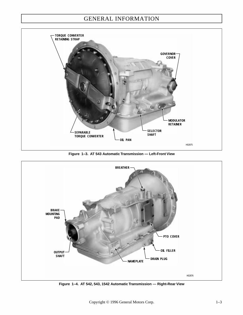
Figure 1–3. AT 543 Automatic Transmission — Left-Front View
Figure 1–4. AT 542, 543, 1542 Automatic Transmission — Right-Rear View
H02875
GOVERNORCOVER
TORQUE CONVERTERRETAINING STRAP
SEPARABLETORQUE CONVERTER
OIL PAN
MODULATORRETAINER
SELECTORSHAFT
H02876
BREATHER
BRAKEMOUNTING
PAD
OUTPUTSHAFT
DRAIN PLUG
OIL FILLER
PTO COVER
NAMEPLATE
Copyright © 1996 General Motors Corp. 1–3

AT 500, 1500 SERIES AUTOMATIC TRANSMISSIONS
Figure 1–5. Transmission Nameplate
1–4. GENERAL DESCRIPTION
a. Automatic, Four Speeds. The AT 500 and1500 Series transmissions have four forward speedsand one reverse. Shifting within the forward ranges se-lected by the operator is fully automatic.
b. Torque Converter and Lockup Clutch. AnAllison three-element torque converter (Foldout 1, 2,or 3) transmits power from the engine to the transmis-sion gearing. The torque converter serves as both a
fluid coupling and a torque multiplier. AT 1500 Seriestransmissions also include a lockup clutch in thetorque converter assembly.
c. Planetary Gearing, Clutches. Ratios for fourforward speeds and reverse are established by plane-tary gearing. The planetary gearing is controlled bymultiple-disc, hydraulic clutches. All gearing is inconstant mesh.
d. Main Control Valve Body. The main controlvalve body consists of a series of spring-loaded spoolvalves which are hydraulically actuated by the mainpressure produced from the charging pump.
1–5. OPERATING INSTRUCTIONS
Refer to SA1334 for operating instructions.
1–6. SPECIFICATIONS AND DATA
The specifications and data in Table 1–1 are applicableto AT 500 and 1500 Series transmissions.
ECAPSORE A
E LI B O MOT UA DETI NU ACI RE MA
FOSR
EKR
OW
TNEME
LPMILARUTLUCIRGADNA
UAW933
DIVISION OFGENERAL MOTORS
CORPORATIONINDIANAPOLIS
INDIANA
SERIAL NO.
XXXXX
XX XXXXX
XXXXXXX
MODELNO.
PART NO.
V01251
Table 1–1. Specifications and Data
INPUT RATINGS — AT 1542 DIESELValue
ParameterGeneral Truck &
Road SweeperTransit & Airport
Shuttle BusMotorhome School Bus
Inner City & Shuttle Bus
Unit
Input SpeedMaximum full load governed speed 4000* 4000* 4000* 4000* 4000* rpmMinimum full load governed speed 2400 2400 2400 2400 2400 rpmMinimum idle speed in drive 500 500 500 500 500 rpm
Input PowerMaximum net 180 (134) 160 (119) 180 (134) 180 (134) 180 (134) hp (kW)
Input TorqueMaximum net 405 (549) 340 (461) 405 (549) 405 (549) 405 (549) lb ft (N·m)
Turbine TorqueMaximum net 709 (961) 585 (793) 709 (961) 709 (961) 709 (961) lb ft (N·m)
Gross vehicle weight (GVW) 22050 (10002) 16540 (7500) 22050 (10002) 16540 (7500) 18520 (8401) lb (kg)Gross combination vehicle weight (GCW) 22050 (10002) N/A 27010 (12252) N/A N/A lb (kg)
* 3200 rpm for TC 290
1–4 Copyright © 1996 General Motors Corp.

GENERAL INFORMATION
INPUT RATINGS — AT 1542 GASOLINE
Value
ParameterGeneral Truck &
Road SweeperTransit & Airport
Shuttle BusMotorhome School Bus
Inner City & Shuttle Bus
Unit
Input SpeedMaximum full load governed speed 4400 4400 4400 4400 4400 rpmMinimum full load governed speed 3200 3200 3200 3200 3200 rpmMinimum idle speed in drive 500 500 500 500 500 rpm
Input PowerMaximum net 200 (149) 160 (119) 200 (149) 200 (149) 200 (149) hp (kW)
Input TorqueMaximum net 405 (549) 340 (461) 405 (549) 405 (549) 405 (549) lb ft (N·m)
Turbine TorqueMaximum net 709 (961) 585 (793) 709 (961) 709 (961) 709 (961) lb ft (N·m)
Gross vehicle weight (GVW) 22050 (10002) 16540 (7500) 22050 (10002) 16540 (7500) 18520 (8401) lb (kg)Gross combination vehicle weight (GCW) 22050 (10002) N/A 27010 (12252) N/A N/A lb (kg)
INPUT RATINGS — AT 1545 DIESEL
Value
ParameterGeneral Truck &
Road SweeperTransit & Airport
Shuttle BusMotorhome School Bus
Inner City & Shuttle Bus
Unit
Input SpeedMaximum full load governed speed 4000* 4000* 4000* 4000* 4000* rpmMinimum full load governed speed 2400 2400 2400 2400 2400 rpmMinimum idle speed in drive 500 500 500 500 500 rpm
Input PowerMaximum net 180 (134) 160 (119) 180 (134) 180 (134) 180 (134) hp (kW)
Input TorqueMaximum net 405 (549) 340 (461) 405 (549) 405 (549) 405 (549) lb ft (N·m)
Turbine TorqueMaximum net 709 (961) 585 (793) 709 (961) 709 (961) 709 (961) lb ft (N·m)
Gross vehicle weight (GVW) 24250 (11000) 21000 (9525) 24250 (11000) 24250 (11000) 24250 (11000) lb (kg)Gross combination vehicle weight (GCW) 24250 (11000) N/A 27010 (12252) N/A N/A lb (kg)
* 3200 rpm fors TC 290
INPUT RATINGS — AT 1545 GASOLINEValue
ParameterGeneral Truck &
Road SweeperTransit & Airport
Shuttle BusMotorhome School Bus
Inner City & Shuttle Bus
Unit
Input SpeedMaximum full load governed speed 4400 4400 4400 4400 4400 rpmMinimum full load governed speed 3200 3200 3200 3200 3200 rpmMinimum idle speed in drive 500 500 500 500 500 rpm
Input PowerMaximum net 200 (149) 160 (119) 200 (149) 200 (149) 200 (149) hp (kW)
Input TorqueMaximum net 405 (549) 340 (461) 405 (549) 405 (549) 405 (549) lb ft (N·m)
Turbine TorqueMaximum net 709 (961) 585 (793) 709 (961) 709 (961) 709 (961) lb ft (N·m)
Gross vehicle weight (GVW) 24250 (11000) 21000 (9525) 24250 (11000) 24250 (11000) 24250 (11000) lb (kg)Gross combination vehicle weight (GCW) 24250 (11000) N/A 27010 (12252) N/A N/A lb (kg)
Note: Conversions between inch and metric units are not necessarily equivalent.
Table 1–1. Specifications and Data (cont’d)
Copyright © 1996 General Motors Corp. 1–5

AT 500, 1500 SERIES AUTOMATIC TRANSMISSIONS
AT 500, 1500 SERIES AUTOMATIC TRANSMISSIONS
Mounting:Engine . . . . . . . . . . . . . . . . . . . . . . . . . . . . . . . . . . . . . . . . . . . . . . . . . . . SAE 3 automotive flywheel
housing with flexplate driveVehicle . . . . . . . . . . . . . . . . . . . . . . . . . . . . . . . . . . . . . . . . . . . . . . . . . . . One vertical mounting pad each
side
Drive . . . . . . . . . . . . . . . . . . . . . . . . . . . . . . . . . . . . . . . . . . . . . . . . . . . . . . . . Flexplate drive, customer fur-nished
Rotation (viewed from input):Input . . . . . . . . . . . . . . . . . . . . . . . . . . . . . . . . . . . . . . . . . . . . . . . . . . . . . ClockwiseOutput (in forward ranges). . . . . . . . . . . . . . . . . . . . . . . . . . . . . . . . . . . . Clockwise
Output location . . . . . . . . . . . . . . . . . . . . . . . . . . . . . . . . . . . . . . . . . . . . . . . . In line with input
Dry weight, approximate (basic configuration):AT 500 Series . . . . . . . . . . . . . . . . . . . . . . . . . . . . . . . . . . . . . . . . . . . . . . 289 lb (131 kg)AT 1500 Series . . . . . . . . . . . . . . . . . . . . . . . . . . . . . . . . . . . . . . . . . . . . . 302 lb (137 kg)
Parking brake (some models) . . . . . . . . . . . . . . . . . . . . . . . . . . . . . . . . . . . . . Mounting provided at rear of transmission case for OEM-supplied parking brake.
Output flange . . . . . . . . . . . . . . . . . . . . . . . . . . . . . . . . . . . . . . . . . . . . . . . . . Supplied by OEM
Hydraulic System:
Fluid capacity, approx. (excluding external circuits)
Fill FromFactory
Initial FillAfter Rebuild
Refill After Servicing
U.S. Qts Liters U.S. Qts Liters U.S. Qts Liters
Shallow oil pan — 4.0 inch (102 mm) 13 12 15 14 9 8.5
Deep oil pan — 5.3 inch (135 mm) 20 19 22 21 16 15
Temperatures*:
Sump (max) . . . . . . . . . . . . . . . . . . . . . . . . . . . . . . . . . . . . . . . . . 250°F (120°C)
To cooler — converter-out (max) . . . . . . . . . . . . . . . . . . . . . . . . 300°F (150°C)
To cooler — retarder-out (max) . . . . . . . . . . . . . . . . . . . . . . . . . 330°F (165°C)
Normal operation (sump) . . . . . . . . . . . . . . . . . . . . . . . . . . . . . . 160–200°F (71–93°C)
Normal operation (converter-out) . . . . . . . . . . . . . . . . . . . . . . . . 180–220ºF (82–104ºC)
Oil filter . . . . . . . . . . . . . . . . . . . . . . . . . . . . . . . . . . . . . . . . . . . . . . . Refer to Paragraph 3–8
Oil pump . . . . . . . . . . . . . . . . . . . . . . . . . . . . . . . . . . . . . . . . . . . . . . Positive displacement
Oil type. . . . . . . . . . . . . . . . . . . . . . . . . . . . . . . . . . . . . . . . . . . . . . . . Refer to Paragraph 3–7
Oil pressure . . . . . . . . . . . . . . . . . . . . . . . . . . . . . . . . . . . . . . . . . . . . Refer to Tables 3–4 through 3–9
Clutches . . . . . . . . . . . . . . . . . . . . . . . . . . . . . . . . . . . . . . . . . . . . . . . . . . Hydraulic-actuated, spring-released, self-compensating for wear
Power takeoff (converter driven):
Mounting . . . . . . . . . . . . . . . . . . . . . . . . . . . . . . . . . . . . . . . . . . . . . . SAE 6-bolt regular duty
Drive gear. . . . . . . . . . . . . . . . . . . . . . . . . . . . . . . . . . . . . . . . . . . . . . 6 pitch, 55 teeth, 20˚ pressure angle
1–6 Copyright © 1996 General Motors Corp.
* Temperature gauge kit available in Parts Catalog.

GENERAL INFORMATION
Table 1–1. Specifications and Data (cont’d)
Location . . . . . . . . . . . . . . . . . . . . . . . . . . . . . . . . . . . . . . . . . . . . . . . Right side (viewed from rear)
Rotation . . . . . . . . . . . . . . . . . . . . . . . . . . . . . . . . . . . . . . . . . . . . . . . Same as engine
Rating (continuous) . . . . . . . . . . . . . . . . . . . . . . . . . . . . . . . . . . . . . . 200 lb ft (270 N·m)
(intermittent) . . . . . . . . . . . . . . . . . . . . . . . . . . . . . . . . . . . . . . 250 lb ft (270 N·m)
Torque Converter:
Type . . . . . . . . . . . . . . . . . . . . . . . . . . . . . . . . . . . . . . . . . . . . . . . . . . Single-stage, 3-element, multiphase
Number of stages . . . . . . . . . . . . . . . . . . . . . . . . . . . . . . . . . . . . . . . . 1
Number of elements . . . . . . . . . . . . . . . . . . . . . . . . . . . . . . . . . . . . . . 3
Stall torque ratio:
AT 540 AT 542 AT 543 AT 545 AT 1542 AT 1545TC275;1.96:1 x x x x xTC290;1.72:1 x x x x xTC350;3.09:1 xTC370;2.51:1 xTC375;2.13:1 xTC380;1.86:1 xLockup Clutch No No No No Yes
(3rd and 4th)Yes
(3rd and 4th)
Typical Shift Sequence (wide open throttle):
AT 500 Series . . . . . . . . . . . . . . . . . . . . . . . . . . . . . . . . . . . . . . . . . . . Auto 1–4 (1C-2C-3C-4C)
AT 1500 Series . . . . . . . . . . . . . . . . . . . . . . . . . . . . . . . . . . . . . . . . . . Auto 1–4 (1C-2C-3C-3L-4L)
Shift modulation:
(Gasoline). . . . . . . . . . . . . . . . . . . . . . . . . . . . . . . . . . . . . . . . . . . . . . Vacuum
(Diesel). . . . . . . . . . . . . . . . . . . . . . . . . . . . . . . . . . . . . . . . . . . . . . . . Mechanical/Electronic
Neutral start and reverse signal switches . . . . . . . . . . . . . . . . . . . . . . . . . Supplied by OEM
Speedometer drive:
Type and size . . . . . . . . . . . . . . . . . . . . . . . . . . . . . . . . . . . . . . . . . . . 13⁄16-20 UNEF thread for SAEregular duty — thread type
Drive gears . . . . . . . . . . . . . . . . . . . . . . . . . . . . . . . . . . . . . . . . . . . . . 5 teeth
Driven gear. . . . . . . . . . . . . . . . . . . . . . . . . . . . . . . . . . . . . . . . . . . . . Supplied by customer
Gearing . . . . . . . . . . . . . . . . . . . . . . . . . . . . . . . . . . . . . . . . . . . . . . . . . . . Constant mesh, spur type, planetary
TRANSMISSION RATIOS (Mechanical**)
Range Clutch(es) Engaged Ratio
Park (AT 542N, 545N, 1545N) First 0Neutral First 0First Forward and first 3.45:1Second Forward and second 2.25:1Third Forward and third 1.41:1Fourth Forward and fourth 1.00:1Reverse Fourth and first 5.02:1
** Overall torque multiplication ratio of transmission (output stalled) is the product of the converter torque multiplication ratio (see torque converter) and
Copyright © 1996 General Motors Corp. 1–7
the mechanical (gear) ratio.

1–8 Copyright © 1996 General Motors Corp.
NOTES
AT 500, 1500 SERIES AUTOMATIC TRANSMISSIONS
AT 500, 1500 SERIES AUTOMATIC TRANSMISSIONS

Section 2 – DESCRIPTION AND OPERATION
2–1. SCOPE
This section describes and explains the operation ofthe components and systems of AT transmissions.Where features are common to all models, no refer-ence will be made to models. Where features are pecu-liar to a model, the model will be noted.
2–2. MOUNTING
a. To Engine. The front of the transmissionhousing is an SAE size 3 flange. This flange is boltedto the rear of the engine.
b. To Vehicle. Two 5⁄8-11 tapped holes at eachside of the transmission are provided for mounting tosupports in the vehicle.
2–3. INPUT DRIVE
a. For models other than AT 543, six tapped lugsare on the front of torque converter 1 (Foldout 7,B) forattachment of a flexible disk drive. The outer bolt cir-cle of the disk drive is bolted to the lugs. The innerbolt circle is bolted to the engine crankshaft or crank-shaft adapter hub.
b. For AT 543 models, six threaded studs are onthe front of torque converter 2 (Foldout 7,A) for the at-tachment of a flexible disk drive using nuts 1.
2–4. TRANSMISSION HOUSING
Transmission housing assembly 6 (Foldout 12,A) iscast aluminum. It houses the clutches and gearing, oilpump, governor, main control valve, and oil pan. Aparking brake mounting surface is provided at the rear.On the right side is a provision for a power takeoff orfor the retarder control valve, depending upon the typeof model.
2–5. TORQUE CONVERTER ASSEMBLY AND LOCKUP CLUTCH
a. Description
(1) AT 500 Series transmissions have torqueconverters that include a pump, a turbine, and a stator.The pump is driven by the engine. The turbine drivesthe turbine shaft. The stator is mounted on a freewheel
clutch, the hub of which is splined to a stationaryground sleeve. The hub of the torque converter pumpdrives the transmission input pressure pump.
(2) AT 1500 Series transmissions areequipped with an automotive-style lockup torque con-verter. In addition to the pump, stator, and turbine as-semblies, a lockup clutch and damper assembly isincorporated. A lockup valve, located in the front sup-port assembly, controls flow through the torque con-verter and provides operation in third and fourthranges.
(3) AT 540, 542, 545, 1542, or 1545 Seriestorque converter 1 (Foldout 7,B) is a closed, weldedunit that cannot be disassembled.
(4) AT 543 torque converter 2 (Foldout 7,A)is a serviceable assembly.
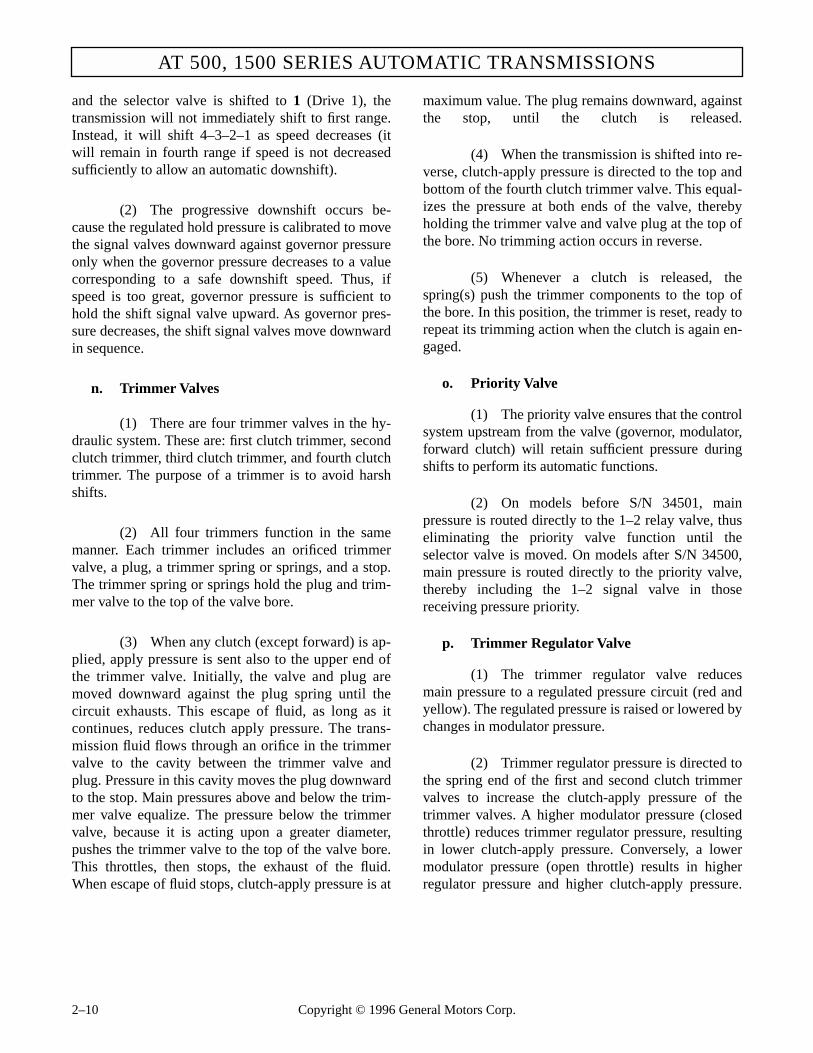
b. Operation (Foldout 1, 2, or 3)
(1) The torque converter assembly is contin-uously filled with transmission fluid, which flowsthrough the converter to cool and lubricate it. Whenthe converter is driven by the engine, the pump vanesthrow the fluid against the turbine vanes. The impactof the fluid against the turbine vanes tends to rotate theturbine.
(2) The turbine, splined to the turbine shaft,transmits torque to the transmission gearing. At engineidle speed, the impact of fluid against the turbine vanesis minimal. At high engine speed the impact of thefluid is much greater on the turbine, and high torque isproduced.
(3) Fluid thrown into the turbine flows to thestator vanes. The stator vanes change the direction ofthe hydraulic flow (when the stator is locked against ro-tation), and directs the fluid to the pump in a directionthat assists the rotation of the pump. It is the redirectionof the fluid by the stator that enables the torque con-verter to multiply input torque.
(4) Greatest torque multiplication occurswhen the turbine is stalled and the pump is rotating atits highest speed. Torque multiplication decreases asthe turbine rotates and approaches the speed of thepump.
(5) When turbine speed approaches thespeed of the pump, fluid flowing to the stator beginsstriking the backs of the stator vanes. This rotates the
Copyright © 1996 General Motors Corp. 2–1

AT 500, 1500 SERIES AUTOMATIC TRANSMISSIONS
stator in the same direction as the turbine and pump.At this point, torque multiplication stops and the con-verter becomes, in effect, a fluid coupling.
(6) Thus, the torque converter accomplishesthree main functions. It acts as a disconnect clutch be-cause little torque is transmitted at engine idle speed.It multiplies torque at low turbine/high pump speed togive greater starting or driving effort when needed.And it acts as a fluid coupling to efficiently transmitengine torque to the transmission gearing during drive,other than idle or starting.
(7) For AT 1500 Series models, the engage-ment of the lockup clutch is controlled by the lockuprelay valve which derives its lockup signal from the3–4 clutch feed pressure. The clutch apply pressurecompresses the lockup clutch plate against the frontcover. Thus, the converter pump and turbine arelocked together and provide a direct drive from theengine to the transmission gearing. As rotationalspeed of the output shaft decreases, the relay valveautomatically releases the lockup clutch. Refer toParagraph 2–19f and g for explanation of the hydrau-lic action.
2–6. OIL PUMP ASSEMBLY
a. Description (Foldout 7,B)
(1) Oil pump assembly 2 includes, in addi-tion to pump components, front support assembly 17,main-pressure regulator components 24 through 27,and, for AT 1500 Series models, lockup valve compo-nents 30 through 33.
(2) The oil pump consists of driven gear 9and drive gear 10 which are located in pump body 8.Pump body 8 is bolted to front support and bearing as-sembly 16.
(3) The front support assembly includes sta-tor shaft 19. Front support 21 closes the front of thetransmission and supports the torque converter, turbineshaft, and forward clutch.
b. Operation (Foldout 7,B)
(1) When the torque converter is rotating, itsrear hub drives pump drive gear 10. Gear 10 is meshedwith the internal teeth of driven gear 9.
(2) The pump gears draw transmission fluidfrom the sump. When the flow of fluid fills all the re-quirements in the transmission, pressure is developed.Valve 27 in support 16 regulates the flow of fluid fromthe pump.
2–7. FORWARD CLUTCH AND TURBINE SHAFT
a. Description (Foldout 8)
(1) The forward clutch and turbine shaft as-sembly connects the converter turbine to the otherclutches and gearing in the transmission during everyoperational phase of the transmission, including PTOoperation or retarder operation.
(2) The turbine shaft is splined to clutchhousing 9 or 14. The external tangs of clutch plates 27engage housing 9 or 14. The internal splines of clutchplates 28 engage hub 26 which transmits torque to thegearing.
(3) Piston 19 is installed in housing 9 or 14and is retained by sixteen springs 20, retainer 21, andsnapring 22. Clutch plates 27 and 28 are held in hous-ing 9 or 14 by fourth clutch driving hub 29 and are re-tained by snapring 30.
(4) Some models are equipped with powertakeoff drive gear 4 or 32. When used, gear 32 issplined to housing 9 and retained by snapring 31.When used, gear 4 is splined to housing 9 and retainedby snaprings 3 and 5.
(5) For models with retarder, refer also toParagraph 2–16.
b. Operation (Foldout 8)
(1) Turbine shaft and housing assembly 7 or11 rotates when the torque converter turbine rotates.Fourth clutch driving hub 29 also rotates along withinternal-splined fourth clutch plates 3 (Foldout 9,A).PTO drive gear 4 or 32 (Foldout 8), when included,also rotates.
(2) When hydraulic pressure is directed tothe piston bore in housing 9 or 14, piston 19 com-presses clutch plates 27 and 28 against driving hub 29.This locks clutch hub 26 to housing 9 or 14. Hub 26 issplined to transmission main shaft 4 (Foldout 10,A).
2–2 Copyright © 1996 General Motors Corp.

DESCRIPTION AND OPERATION
(3) When the converter turbine rotates andthe forward clutch is applied, the transmission mainshaft is rotated. This drives the transmission gear set,and drives the output shaft in any forward range.
(4) The forward clutch is engaged only dur-ing operation in a forward range, and is always pairedwith another clutch (either first, second, third, orfourth). It is disengaged during neutral and reverse.
(5) In neutral, the forward clutch housing ro-tates, driving the power takeoff, if so equipped. In re-verse, the forward clutch housing rotates to drive thefourth clutch (which is applied in combination withthe first clutch to obtain reverse).
(6) For models with retarder, refer also toParagraph 2–16.
2–8. FOURTH CLUTCH
a. Description (Foldout 9,A)
(1) The fourth clutch includes housing as-sembly 11, piston 8, five external-tanged clutch plates4, five internal-splined plates 3, and, for models with-out retarder, backplate 2. For models with retarder, re-tarder housing 36 (Foldout 8) functions as the fourthclutch backplate.
(2) Piston 8 (Foldout 9,A) is installed inhousing 13, and retained by sixteen springs 7, retainer6, and snapring 5. External-tanged plates 4 engagehousing 13. Internal-splined plates 3 are splined tofourth clutch driving hub 29 (Foldout 8). For modelswithout retarder, plates 3 and 4 (Foldout 9,A) are re-tained in housing 13 by clutch backplate 2 andsnapring 1. For models with retarder, plates 3 and 4 areretained in housing 13 by retarder housing 36 (Foldout8).
(3) The hub of housing 13 (Foldout 9,A) issplined to sun gear shaft 3 (Foldout 10,A). The outersplines on housing 13 (Foldout 9,A) engage internal-splined plates 3 (Foldout 9,B) of the third clutch.
b. Operation (Foldout 9,A)
(1) When the fourth clutch is released, inter-nal-splined plates 3 are free of external-tanged plates4. Plates 3 rotate independent of housing 13, whetherhousing 13 is stopped or has a different speed or direc-tion of rotation.
(2) When hydraulic pressure is directed tothe piston cavity in housing 13, piston 8 compressesplates 3 and 4 against backplate 2 or against retarderhousing 36 (Foldout 8). This locks internal-splinedplates 3 (Foldout 9,A) to external-tanged plates 4 and,in turn, to housing 13.
(3) When the fourth clutch is engaged, it islocked to fourth clutch driving hub 29 (Foldout 8) androtates with the turbine shaft.
(4) In fourth range, turbine shaft rotation istransmitted to sun gear shaft 3 (Foldout 10,A) and totransmission main shaft 4 by the engaged forwardclutch. The result is direct drive to the output shaft.
(5) In reverse, turbine shaft rotation is trans-mitted to sun gear shaft 3 while the first clutch (Fold-out 10,B) is engaged, resulting in reverse rotation ofthe transmission output shaft.
2–9. SECOND AND THIRD CLUTCH AND CENTER SUPPORT
a. Description (Foldout 9,B)
(1) Third clutch includes items 1 through 11.Second clutch includes items 16 through 25. Centersupport assembly 13 serves the two clutches. The frontside of support 15 receives third clutch piston 9. Therear side of support 15 receives second clutch piston18. Center support 15 directs fluid to both of theseclutches, as well as to the fourth clutch.
(2) External-tanged clutch plates 4 and 23engage the transmission housing, and are always sta-tionary. Internal-splined plates 3 of the third clutch en-gage housing 13 (Foldout 9,A) of the fourth clutch.Internal-splined plates 24 (Foldout 9,B) of the secondclutch engage the external splines of front planetaryassembly 8 (Foldout 10,A).
b. Operation of Third Clutch (Foldout 9,B)
(1) When the third clutch is released, inter-nal-splined plates 3 rotate with fourth clutch housing13 (Foldout 9,A). The third clutch is released in allranges except third.
(2) When hydraulic pressure is directed tothe third clutch piston cavity (front) of center support15 (Foldout 9,B), piston 9 compresses plates 3 and 4against backplate 2. This anchors clutch plates 3 and 4,
Copyright © 1996 General Motors Corp. 2–3

AT 500, 1500 SERIES AUTOMATIC TRANSMISSIONS
and fourth clutch housing 13 (Foldout 9,A) to thetransmission housing, stopping rotation. Since housing13 is splined to sun gear shaft 3 (Foldout 10,A), theshaft is held stationary. This provides a reaction for thegearing and causes the planetaries to produce thirdrange.
c. Operation of Second Clutch (Foldout 9,B)
(1) When the second clutch is released, in-ternal-splined plates 24 rotate with front planetary car-rier assembly 8 (Foldout 10,A). The second clutch isreleased during all ranges except second.
(2) When hydraulic pressure is directed tothe second clutch piston cavity (rear) of center support15 (Foldout 9,B), piston 18 compresses plates 23 and24 against backplate 25. This anchors internal-splinedplates 24 and external-tanged plates 23 to the trans-mission housing.
(3) The internal-splines of plates 24 aresplined to front planetary carrier assembly 8 (Foldout10,A), holding the carrier stationary. A compound ar-rangement in the planetaries produces second range.
2–10. FIRST CLUTCH
a. Description (Foldout 10,B)
(1) The first clutch includes piston 9, sevenexternal-tanged clutch plates 4, seven internal-splinedclutch plates 3, and backplate 2.
(2) Piston 9 is in the rear of the transmissionhousing. The external tangs of clutch plates 4 engagethe transmission housing and are always stationary. In-ternal-splined plates 3 engage rear planetary ring gear5 (Foldout 10,B) or 53 (Foldout 10,A).
(3) Piston 9 (Foldout 10,B) is retained in thetransmission housing by twenty-two springs 8, retainer7, and snapring 6. Backplate 2 and clutch plates 3 and4 are retained in the transmission housing by snapring1.
b. Operation (Foldout 10,B)
(1) When the first clutch is released, inter-nal-splined plates 3 and rear planetary ring gear 5 or53 (Foldout 10,A) rotate. The first clutch is releasedduring operation in all ranges except neutral, first, andreverse.
(2) When hydraulic pressure is directed tothe first clutch piston cavity, piston 9 (Foldout 10,B)compresses clutch plates 3 and 4 against backplate 2.This locks internal-splined plates 3 to external-tangedplates 4, which are anchored to the transmission hous-ing. Plates 3, splined to the rear planetary ring gear,hold the ring gear stationary.
(3) The stationary ring gear provides a reac-tion for the planetary gearing to produce either firstrange or reverse.
(4) In first range, the driving member is rearplanetary sun gear 31 (Foldout 10,A), which receivestorque through the turbine shaft, the engaged forwardclutch, and the transmission main shaft.
(5) In reverse, the driving member is centersun gear 19 (Foldout 10,A), which receives torquethrough the turbine shaft, the engaged fourth clutch,and sun gear shaft 3. First range is a simple planetaryaction (involving only one planetary). Reverse is acompound planetary action (involving two planetarysets).
2–11. PLANETARY GEAR UNIT
a. Description (Foldout 10,A)
(1) The planetary gear unit includes all ofthe gears and shafts in the transmission except the tur-bine shaft and the rear planetary ring gear.
(2) Three planetary gear sets are included inthe assembly. These are called front planetary, centerplanetary, and rear planetary.
(3) The front planetary includes sun gear 6,carrier assembly 8, and ring gear 18. The center plane-tary includes sun gear 19, carrier assembly 20, andring gear 30. The rear planetary includes sun gear 31,carrier assembly 36, and ring gear 5 (Foldout 10,B).
(4) The three planetary sets are intercon-nected by sun gear shaft 3 (Foldout 10,A), main shaft4, and connecting drum 28. This interconnection of theplanetary input, reaction, and output elements, andconnection of clutches to the shafts and planetary ele-ments, produces four forward ranges and reverse.
b. Operation. Refer to Paragraph 2–19.
2–4 Copyright © 1996 General Motors Corp.

DESCRIPTION AND OPERATION
2–12. SPEEDOMETER DRIVE/SPEED SENSOR WHEEL
a. Description (Foldout 12,B)
(1) The speedometer drive consists of drivegear 2 and provision for mounting the driven gear as-sembly in the transmission housing. Drive gear 2 is aworm gear with a left-hand helix. It is concentric withthe transmission output shaft. The drive gear isclamped between adjacent components for rotationaldrive.
(2) Speed sensor wheel 9 is provided formodels that are equipped with an electronic speed-ometer. The 16-tooth wheel provides a rotating pulsethat can be read by an electronic speed sensor.
b. Operation (Foldout 12,B)
(1) When the transmission output shaft ro-tates, drive gear 2 or speed sensor wheel 9 rotates.
(2) For mechanical speedometers, the drivengear, supplied by the vehicle manufacturer, rotatesclockwise during forward operation (viewed at thedrive cable connection on the transmission).
(3) For electronic models, the speed sensor,supplied by the vehicle manufacturer, reads the outputspeed by “counting” the pulses produced by the teethof the speed sensor wheel.
2–13. GOVERNOR
a. Description (Foldout 12,A). Governor assem-bly 19 is a centrifugal (flyweight) governor, driven bydrive gear 1 (Foldout 12,B) and mounted on the trans-mission output shaft. It is retained by cover 22 (Fold-out 12,A).
b. Operation (Foldout 12,A). When the governorrotates, centrifugal force causes weights to move out-ward which moves a valve to admit main pressure tothe governor circuit. Governor pressure is regulatedwhen the centrifugal force of the weights is balancedby opposing hydraulic pressure. Governor pressurevaries with transmission output speed, increasing asoutput speed increases. Governor pressure, in combi-nation with modulator pressure, controls the automaticshifting of the transmission.
2–14. MODULATOR
a. Vacuum Modulator (Foldout 12,A)
(1) Vacuum modulator 26 is calibrated andsealed at the factory.
(2) The position of the diaphragm in themodulator varies with vehicle speed, load, and enginethrottle opening. When the diaphragm moves, themodulator valve is affected, increasing or decreasingmodulation pressure. Modulator and governor pres-sures control the automatic selection of transmissionranges.
b. Mechanical Modulator
(1) The mechanical modulator is attached tothe transmission and activated by a cable.
(2) The cable is connected to the fuel controllever at one end and the modulator valve actuator atthe other. The fuel control lever moves the cable, con-trolling the modulator valve.
c. Electric Modulator
(1) An electric modulator can be used withelectronic or non-electronic engines — any enginewhich can provide an On/Off signal based on throttle/pedal position.
(2) The 12-volt modulator assembly and the24-volt modulator assembly utilize an electronic sig-nal to stroke the transmission modulator pin from theclosed-throttle position to the full-throttle position.The result is step-modulation.
(3) Step-modulation is a two-phase modula-tion schedule which utilizes a closed-throttle shiftschedule until the throttle position is greater than 80–85percent, then, remains at a full-throttle shift scheduleuntil the throttle position is less than 60–65 percent.
(4) Electric modulators are compatible withan electronically-controlled engine that can provide anOn/Off signal based on throttle position. Consult the re-spective engine manufacturer to identify the wire thatprovides this signal. Electronic modulation can also beapplicable in mechanically-controlled engines. Themodulating system will still require a 12- or 24-volt (dc)signal to stroke the transmission modulator valve.
Copyright © 1996 General Motors Corp. 2–5

AT 500, 1500 SERIES AUTOMATIC TRANSMISSIONS
2–15. OIL PAN AND FILTER
a. Description (Foldout 12,B)
(1) Oil pan 26 or 33 is a pressed steel assem-bly providing openings for draining the transmissionfluid and for mounting a fill tube and dipstick.
(2) Filter assembly 21, 38, or 46 is either apaper element retained by a steel casing or a brassscreen assembly. The filter tube is not integral to thefilter.
(3) Transmission fluid from the sump isdrawn through the filter by the input oil pump and di-rected to the hydraulic system. A washer-head screwattaches the filter to the valve body.
(4) Deep pan units also use spacer 41 or 49and a longer intake tube 40 or 48 between the filter andthe valve body.
b. Function (Foldout 12,B)
(1) Oil pan 26 or 33 serves as the transmis-sion fluid sump and covers the main control valvebody assembly and the filter. The oil pan must be re-moved from the bottom of the transmission to replacethe filter.
(2) The filter assembly screens all transmis-sion fluid entering the hydraulic system. The fluidchange interval is influenced by whether the transmis-sion is fitted with a paper or with a brass filter. Refer toParagraph 3–8.
(3) In some models, a magnet in the oil panhelps to accumulate any metal particles in the fluidsupply.
2–16. HYDRAULIC RETARDER
a. Description
(1) AT 542/545R models have a retarder lo-cated on the input side of the transmission that is de-signed for auxiliary braking for downhill speed con-trol. This 160 hp retarder has a two-stage capacitythat, in conjunction with selection of the appropriateranges, can be used to tailor desired retardation perfor-mance to particular duty cycles.
(2) A cross-section of the AT 542/545R isshown on Foldout 3. The main retarder componentsinternal to the transmission are front stator 1 (Foldout8), the rotor which is a part of forward clutch housing14, and rear stator 35.
(3) The AT retarder has a dual torus design.The retarder rotor provides high flow and torque gen-eration. Front stator 1 and rear stator 35 are both sta-tionary.
(4) The rotating element (rotor) of the re-tarder is cast on the OD of forward clutch housing 13.The rotor blades occupy approximately the same areathat the optional PTO gear occupies on a PTO-equipped AT transmission. The valve body for the re-tarder mounts to the transmission PTO pad. Transmis-sion fluid is transferred to and from the retarderthrough tubes that connect the externally-mounted re-tarder controls to retarder housing 37.
b. Operation
(1) The hydraulic system introduces trans-mission fluid through the tips of the rear stator bladesin rear housing assembly 35 (Foldout 8), which is anextremely low pressure area. The fluid exits the torusthrough a slot at the OD of the blades.
(2) The retarder fluid is transferred from theretarder housing to the controls through two tubes. Thecontrols turn on the retarder, as well as perform capac-ity regulation and cooler oil routing.
(3) The retarder is electronically activated bysolenoids (Foldout 4,A, B, and C). Main-pressurefrom Solenoid H activates the autoflow valve. Thisvalve routes transmission cooler flow and fills the re-tarder cavity through a regulator valve and priorityvalve system.
(4) The routing of the fluid to the coolingsystem is accomplished with the autoflow valve. Whenclosed, the transmission fluid is routed through bothprimary and secondary coolers and the filter system.When in retarder mode, the auto-flow valve opens anddirects converter-out transmission fluid through thesecondary cooler and filter system. Retarder fluidflows through the primary cooler only.
2–6 Copyright © 1996 General Motors Corp.

DESCRIPTION AND OPERATION
(5) The retarder priority valve allows theregulator valve to feed the retarder if transmissionfluid pressure is at an acceptable level. This is done toprevent the apply of the retarder from occurring ifmain pressure is at a low enough level that the trans-mission would be unable to acceptably transmit the re-tarder torque. The priority valve also acts as a retardercapacity interrupt during transmission range shifts,preventing transmission clutch overloads. The priorityvalve strokes as a result of the usual transmission mainpressure drop that occurs when filling a clutch during arange shift. This pressure drop results in the retarderpriority valve closing, and retarder capacity being re-duced during the shift. This interruption in retarder isso brief that no negative impact on performance isnoted. The brief capacity reduction also improves thequality of the downshift while the retarder is activated.
(6) The retarder control system has the abil-ity to incorporate two levels of braking, using a specialregulator valve. The regulator valve balances retardercharging pressure against a resisting force that variesat two levels dependent upon the capacity level cho-sen.
(7) For the lower capacity (50 percent), thevalve spring force acts alone to balance the chargingpressure to produce torque. The first stage solenoid(Solenoid H) is the only solenoid energized for this ca-pacity level.
(8) The control system for the higher capac-ity level (100 percent) uses the second stage solenoid(Solenoid F) in addition to the first stage solenoid. Thehydraulic output from Solenoid H supplements thespring force via a small plug valve. This raises thecharging pressure required to establish a force balanceon the regulator valve, resulting in higher braking out-put when both solenoids are energized.
(9) Retarder torque is generated by the rotat-ing rotor blades which pump transmission fluid into aset of stationary stator blades. The stationary blades, inturn, redirect the fluid back to the rotating blades. Theresult is a very high velocity hydraulic flow around thetorus and the absorption of a large amount of kineticenergy. Cooler flow results from the large pressuredrop that the high velocity fluids create between theinlet and outlet locations.
2–17. MAIN CONTROL VALVE ASSEMBLY
Main control valve body assembly 1 (Foldout 11) in-cludes valves, springs, and other components whichrespond to the manual selection of ranges and controlthe automatic shifting of the transmission. The valvebody assembly is bolted to the bottom of the transmis-sion housing. The transmission housing is channeledto direct the flow of transmission fluid between thevalve body and clutches and other components.
2–18. HYDRAULIC SYSTEM
NOTE:
References to up, down, left, or right refer to posi-tions or movements of components on Foldout 5 or 6.
a. System Functions. The hydraulic system gen-erates, directs, and controls the pressure and flow ofhydraulic fluid within the transmission. Hydraulicfluid (transmission oil) is the power transmitting me-dium in the torque converter. Its velocity drives thetorque converter turbine. Its flow cools and lubricatesthe transmission. Its pressure operates the controlvalves and applies the clutches.
b. System Schematic (Foldout 5 or 6). Color-coded foldouts of the hydraulic systems are presentedat the back of this manual. The illustrations representthe system as it functions in neutral with the engineidling.
c. Filter, Pump Circuit. Transmission fluid isdrawn from the sump through a filter screen by the in-put-driven charging pump. Fluid discharged by thepump flows to the main-pressure regulator valve. Abypass circuit returns fluid to the pump intake whenmain pressure reaches its scheduled value.
d. Main-Pressure Circuit (Red)
(1) Transmission fluid from the pump flowsinto the bore surrounding the main-pressure regulatorvalve, into an internal passage of the valve, and to theupper end of the valve. Pressure at the upper end of thevalve moves the valve downward until fluid flows tothe torque converter and, if pump flow is of sufficientvolume, to the bypass circuit. Spring force below the
Copyright © 1996 General Motors Corp. 2–7

AT 500, 1500 SERIES AUTOMATIC TRANSMISSIONS
valve, balanced with hydraulic pressure above thevalve, creates a regulated main pressure.
(2) The main-pressure circuit to the remain-der of the hydraulic system is connected to the main-pressure regulator valve bore at the same point as thepump outlet. Before S/N 34501 (AT 540, 543 models),main pressure is directed to seven points in the system.These are the 3–4 shift signal valve, 2–3 shift signalvalve, 1–2 shift signal valve, selector valve, 1–2 relayvalve, modulator valve, and governor valve. After S/N 34500 (AT 540, 543 models) and for all other ATmodels, the trimmer regulator valve and the priorityvalve are also in the main-pressure circuit.
(3) Although main pressure is controlled pri-marily by the force of the spring below the regulatorvalve, modulator pressure (earlier models), and for-ward regulator pressure reduce main pressure.
(4) On AT 542, 543, 545, 1542, and 1545models, main pressure remains constant because thereis no modulated pressure at the main-pressure regula-tor valve.
e. Converter-In (Yellow), Converter-Out(Orange), Lubrication (Green) Circuits
(1) Converter-in fluid flows through thetorque converter continuously to keep it filled and tocarry off the heat generated in the converter.
(2) Converter-out fluid, leaving the torqueconverter, flows to an external cooler (supplied by thevehicle or power unit manufacturer). A flow of air orwater over or through the cooler removes the heatfrom the transmission fluid.
(3) Cooler-out fluid returns to componentsrequiring continuous flow lubrication. Lubricationfluid then returns to the sump.
f. Selector Valve, Neutral, Forward RegulatorCircuit (Orange and Yellow)
(1) The selector valve is manually shifted toselect the operating range desired. The selector valveestablishes the hydraulic circuit for operation in therange selected. Shifting within any range is automatic,depending upon speed and throttle position.
(2) Neutral, forward regulator pressure is di-rected from the selector valve to the main-pressure
regulator valve when the selector valve is at any posi-tion except reverse. In neutral and in all forwardranges, this pressure pushes downward on the main-pressure regulator valve and reduces main pressure. Inreverse, regulator pressure is absent, permitting ahigher main pressure.
g. Governor Valve, Governor Circuit(Green and White)
(1) Governor feed is main pressure directedto the governor valve. The governor controls the po-sition of the governor valve, which determines thepressure in the governor circuit. When the trans-mission output is not rotating, governor pressure isapproximately 2 psi (14 kPa). When the transmis-sion output rotates, governor pressure varies withthe speed of rotation. The greater the speed of rota-tion, the greater the governor pressure.
(2) Governor pressure is directed to the 1–2,2–3, and 3–4 shift valves.
h. Modulator Pressure Circuit (Red and Green)
(1) Modulator pressure is a regulated, re-duced pressure derived from main pressure at the mod-ulator valve. Pressure is applied by either a vacuummodulator or a mechanical actuator. At high vacuum(closed throttle), all pressure is removed from the actu-ator pin allowing the valve to move rightward. Lowvacuum (open throttle) increases the pressure on theactuator pin, due to the spring force in the vacuummodulator, moving the valve leftward.
(2) When the modulator pressure valvemoves to the left, modulator pressure is reduced; whenit moves to the right, modulator pressure is increased.Since engine vacuum varies with load, throttle open-ing, and engine speed, the position of the modulatorpressure valve, and modulator pressure vary also. Onthe AT 542, 543, 545, 1542, and 1545 models, thisvarying pressure is directed to the three shift signalvalves and to the trimmer regulator valve. On the AT540, modulated pressure is directed also to the main-pressure regulator valve.
(3) At the 1–2, 2–3, and 3–4 shift signalvalves, modulator and governor pressures act to up-shift the valves in proper sequence. At a given gover-nor pressure, the introduction of modulator pressureupshifts a signal valve. A decrease or removal of mod-
2–8 Copyright © 1996 General Motors Corp.

DESCRIPTION AND OPERATION
ulator pressure causes a downshift if governor pressurealone will not hold the valve upward against springforce.
(4) For the earlier models main-pressure reg-ulator valve, modulator pressure exerts a downwardforce on the valve. An increase in modulator pressurecauses a decrease in main pressure; a decrease in mod-ulator pressure causes an increase in main pressure.
(5) Before S/N 34501, modulator pressure isblocked by the separator plate at the trimmer regulatorvalve. The trimmer regulator valve is either isolatedand not functional or is not present.
(6) After S/N 34500, modulator pressure isdirected to the trimmer regulator valve, exerting anupward force against its spring. This causes a reduc-tion in trimmer regulator pressure at the trimmervalves.
i. Clutch Circuits
(1) Each of the five clutches has its own cir-cuit. Each clutch, except forward, is connected to a re-lay valve and a trimmer valve. The forward clutch isconnected directly to the selector valve. It does not re-quire connection to a trimmer valve because its appli-cation (except in a neutral-to-first range shift) precedesthe application of an additional clutch, which istrimmed.
(2) The first clutch circuit (red and white)connects the clutch to the 1–2 relay valve and to thefirst clutch trimmer valve. In neutral, the 1–2 relayvalve is held upward by spring force, and main pres-sure is directed to the first clutch circuit. The 1–2 relayvalve does not move downward unless the 1–2 signalline is charged. This will not occur in neutral becausethere is no governor pressure to shift the 1–2 signalvalve.
j. Hold Regulator Valve
(1) The various hold ranges limit the high-est range attainable by introducing a pressure whichprevents governor pressure from upshifting the signalvalves. This pressure is a regulated, reduced pressurederived from main pressure at the hold regulatorvalve.
(2) Hold regulator pressure at each shift sig-nal valve will push the modulator valve upward, andhold the shift valve down against governor pressure.Thus, when hold regulator pressure is present, an up-shift can occur at that shift signal valve only with ex-cessive overspeed.
k. Automatic Upshifts
(1) When the transmission is operating infirst range (or second range, earlier model transmis-sions with second range start), with the selector valveat D (Drive), a combination of governor pressure andmodulator pressure, or governor pressure alone, willupshift the transmission to the next range. At closed orpart throttle, modulator pressure assists governor pres-sure. At full throttle, there is no modulator pressure.Thus, upshifts occur sooner when the throttle is closedand are delayed when the throttle is open.
(2) When governor pressure is sufficient, thefirst upshift will occur. A further increase in governorpressure (output speed) will cause subsequent up-shifts.
(3) In any automatic upshift, the shift signalvalve acts first. This directs a shift signal pressure tothe relay valve. The relay valve moves downward, ex-hausting the applied clutch and applying a clutch forthe next higher range.
l. Automatic Downshifts
(1) Automatic downshifts, like upshifts, arecontrolled by governor and modulator pressures.Downshifts occur in sequence as governor pressureand/or modulator pressures decrease. Low modulatorpressure (open throttle) will cause a sooner downshift;high modulator pressure (closed throttle) will cause adelayed downshift.
(2) In any automatic downshift, the shift sig-nal valve acts first. This exhausts the shift signal hold-ing the relay valve downward. The relay valve thenmoves upward, exhausting the applied clutch and ap-plying the clutch for the next lower range.
m. Downshift Inhibiting
(1) Inherent in the system is a means for pre-venting downshifts at a too rapid rate. For example, ifthe vehicle is traveling at a high speed in fourth range
Copyright © 1996 General Motors Corp. 2–9
AT 500, 1500 SERIES AUTOMATIC TRANSMISSIONS
and the selector valve is shifted to 1 (Drive 1), thetransmission will not immediately shift to first range.Instead, it will shift 4–3–2–1 as speed decreases (itwill remain in fourth range if speed is not decreasedsufficiently to allow an automatic downshift).
(2) The progressive downshift occurs be-cause the regulated hold pressure is calibrated to movethe signal valves downward against governor pressureonly when the governor pressure decreases to a valuecorresponding to a safe downshift speed. Thus, ifspeed is too great, governor pressure is sufficient tohold the shift signal valve upward. As governor pres-sure decreases, the shift signal valves move downwardin sequence.
n. Trimmer Valves
(1) There are four trimmer valves in the hy-draulic system. These are: first clutch trimmer, secondclutch trimmer, third clutch trimmer, and fourth clutchtrimmer. The purpose of a trimmer is to avoid harshshifts.
(2) All four trimmers function in the samemanner. Each trimmer includes an orificed trimmervalve, a plug, a trimmer spring or springs, and a stop.The trimmer spring or springs hold the plug and trim-mer valve to the top of the valve bore.
(3) When any clutch (except forward) is ap-plied, apply pressure is sent also to the upper end ofthe trimmer valve. Initially, the valve and plug aremoved downward against the plug spring until thecircuit exhausts. This escape of fluid, as long as itcontinues, reduces clutch apply pressure. The trans-mission fluid flows through an orifice in the trimmervalve to the cavity between the trimmer valve andplug. Pressure in this cavity moves the plug downwardto the stop. Main pressures above and below the trim-mer valve equalize. The pressure below the trimmervalve, because it is acting upon a greater diameter,pushes the trimmer valve to the top of the valve bore.This throttles, then stops, the exhaust of the fluid.When escape of fluid stops, clutch-apply pressure is at
maximum value. The plug remains downward, againstthe stop, until the clutch is released.
(4) When the transmission is shifted into re-verse, clutch-apply pressure is directed to the top andbottom of the fourth clutch trimmer valve. This equal-izes the pressure at both ends of the valve, therebyholding the trimmer valve and valve plug at the top ofthe bore. No trimming action occurs in reverse.
(5) Whenever a clutch is released, thespring(s) push the trimmer components to the top ofthe bore. In this position, the trimmer is reset, ready torepeat its trimming action when the clutch is again en-gaged.
o. Priority Valve
(1) The priority valve ensures that the controlsystem upstream from the valve (governor, modulator,forward clutch) will retain sufficient pressure duringshifts to perform its automatic functions.
(2) On models before S/N 34501, mainpressure is routed directly to the 1–2 relay valve, thuseliminating the priority valve function until theselector valve is moved. On models after S/N 34500,main pressure is routed directly to the priority valve,thereby including the 1–2 signal valve in thosereceiving pressure priority.
p. Trimmer Regulator Valve
(1) The trimmer regulator valve reducesmain pressure to a regulated pressure circuit (red andyellow). The regulated pressure is raised or lowered bychanges in modulator pressure.
(2) Trimmer regulator pressure is directed tothe spring end of the first and second clutch trimmervalves to increase the clutch-apply pressure of thetrimmer valves. A higher modulator pressure (closedthrottle) reduces trimmer regulator pressure, resultingin lower clutch-apply pressure. Conversely, a lowermodulator pressure (open throttle) results in higherregulator pressure and higher clutch-apply pressure.
2–10 Copyright © 1996 General Motors Corp.
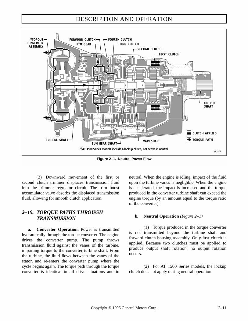
DESCRIPTION AND OPERATION
Figure 2–1. Neutral Power Flow
������������
������������
��
����
��
�� ��
��������������������������������������������������������������������������������
��
����
����
������
�� �
��
����
���������
������
����
�������
���
���
������������������������������������
���������
��������
���
� �
�
�
�
����
����
����
��
��
����
�����������
�
��
����
����
��
V02877
TURBINE SHAFTSUN GEAR SHAFT
PTO GEARFORWARD CLUTCH
THIRD CLUTCH
SECOND CLUTCH
FIRST CLUTCH
FOURTH CLUTCH✽ TORQUECONVERTER
ASSEMBLY
MAIN SHAFT TORQUE PATH
✽ AT 1500 Series models include a lockup clutch, not active in neutral
CLUTCH APPLIED
OUTPUTSHAFT
(3) Downward movement of the first orsecond clutch trimmer displaces transmission fluidinto the trimmer regulator circuit. The trim boostaccumulator valve absorbs the displaced transmissionfluid, allowing for smooth clutch application.
2–19. TORQUE PATHS THROUGH TRANSMISSION
a. Converter Operation. Power is transmittedhydraulically through the torque converter. The enginedrives the converter pump. The pump throwstransmission fluid against the vanes of the turbine,imparting torque to the converter turbine shaft. Fromthe turbine, the fluid flows between the vanes of thestator, and re-enters the converter pump where thecycle begins again. The torque path through the torqueconverter is identical in all drive situations and in
neutral. When the engine is idling, impact of the fluidupon the turbine vanes is negligible. When the engineis accelerated, the impact is increased and the torqueproduced in the converter turbine shaft can exceed theengine torque (by an amount equal to the torque ratioof the converter).
b. Neutral Operation (Figure 2–1)
(1) Torque produced in the torque converteris not transmitted beyond the turbine shaft andforward clutch housing assembly. Only first clutch isapplied. Because two clutches must be applied toproduce output shaft rotation, no output rotationoccurs.
(2) For AT 1500 Series models, the lockupclutch does not apply during neutral operation.
Copyright © 1996 General Motors Corp. 2–11

AT 500, 1500 SERIES AUTOMATIC TRANSMISSIONS
Figure 2–2. First Range Power Flow
������������
������������
��
����
��
�� ��
��������������������������������������������������������������������������������
��
����
����
������
�� �
��
����
���������
������
����
�������
���
���
������������������������������������
���������
��������
���
� �
�
�
�
����
����
����
��
��
����
�����������
�
��
����
����
��
V02878
TURBINE SHAFTSUN GEAR SHAFT
PTO GEARFORWARD CLUTCH
THIRD CLUTCH
SECOND CLUTCH
FIRST CLUTCH
FOURTH CLUTCH✽ TORQUECONVERTER
ASSEMBLY
MAIN SHAFT TORQUE PATH
✽ AT 1500 Series models include a lockup clutch, not active in first range
CLUTCH APPLIED
OUTPUTSHAFT
c. First-Range Operation (Figure 2–2)
(1) The forward and first clutches are ap-plied. The first clutch application anchors the rearplanetary ring gear against rotation. The forwardclutch application locks the turbine shaft and transmis-sion main shaft together to rotate as a unit. The rearsun gear is splined to the main shaft and rotates with itand, in turn, rotates the rear planetary pinions. The
pinions are part of the carrier assembly which issplined to the transmission output shaft. With the rearring gear held stationary by the applied first clutch andthe rear sun gear rotating the pinions, the rear plane-tary carrier rotates within the ring gear and drives theoutput shaft at a speed reduction of 3.45:1.
(2) For AT 1500 Series models, the lockupclutch does not apply during first range operation.
2–12 Copyright © 1996 General Motors Corp.

DESCRIPTION AND OPERATION
Figure 2–3. Second Range Power Flow
������������
������������
��
����
��
�� ��
��������������������������������������������������������������������������������
��
����
����
������
�� �
��
����
���������
������
����
�������
���
���
������������������������������������
���������
��������
���
� �
�
�
�
����
����
����
��
��
����
�����������
�
��
����
����
��
V02879
TURBINE SHAFTSUN GEAR SHAFT
PTO GEARFORWARD CLUTCH
THIRD CLUTCH
SECOND CLUTCH
FIRST CLUTCH
FOURTH CLUTCH✽ TORQUECONVERTER
ASSEMBLY
MAIN SHAFT TORQUE PATH
✽ AT 1500 Series models include a lockup clutch, not active in second range
CLUTCH APPLIED
OUTPUTSHAFT
d. Second-Range Operation (Figure 2–3)
(1) The forward and the second clutches areapplied. The second clutch application anchors thecarrier of the front planetary carrier assembly againstrotation. The forward clutch application locks the tur-bine shaft and main shaft together to rotate as a unit.The rear sun gear is splined to both the rotating mainshaft and the center ring gear and all three parts rotateat turbine speed. With the carrier of the front planetarycarrier assembly anchored against rotation, the rotat-ing center ring gear rotates the center sun gear via theplanetary pinions. This sun gear is splined to the sun
gear shaft assembly to which the front sun gear is alsosplined. The rotating front sun gear rotates the frontcarrier pinions whose carrier is anchored against rota-tion by the applied second clutch. In turn, the rotatingfront carrier pinions rotate the front ring gear, which,along with the center carrier, is splined, via the plane-tary connecting drum and rear carrier assembly, to theoutput shaft. Due to this compounding action of thefront and center planetary gear sets, there is an outputspeed reduction of 2.25:1.
(2) For AT 1500 Series models, the lockupclutch does not apply during second range operation.
Copyright © 1996 General Motors Corp. 2–13
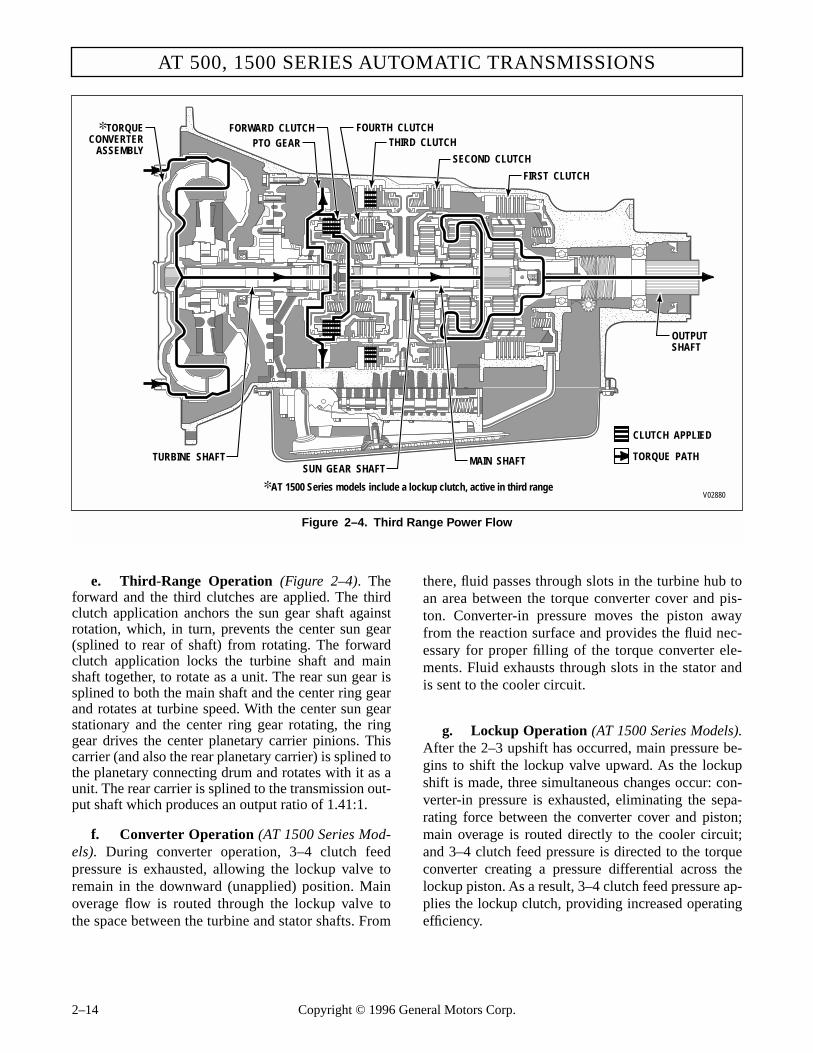
AT 500, 1500 SERIES AUTOMATIC TRANSMISSIONS
Figure 2–4. Third Range Power Flow
������������
������������
��
����
��
�� ��
��������������������������������������������������������������������������������
��
����
����
������
�� �
��
����
���������
������
����
�������
���
���
������������������������������������
���������
��������
���
� �
�
�
�
����
����
����
��
��
����
�����������
�
��
����
����
��
V02880
TURBINE SHAFTSUN GEAR SHAFT
PTO GEARFORWARD CLUTCH
THIRD CLUTCH
SECOND CLUTCH
FIRST CLUTCH
FOURTH CLUTCH✽ TORQUECONVERTER
ASSEMBLY
MAIN SHAFT TORQUE PATH
✽ AT 1500 Series models include a lockup clutch, active in third range
CLUTCH APPLIED
OUTPUTSHAFT
e. Third-Range Operation (Figure 2–4). Theforward and the third clutches are applied. The thirdclutch application anchors the sun gear shaft againstrotation, which, in turn, prevents the center sun gear(splined to rear of shaft) from rotating. The forwardclutch application locks the turbine shaft and mainshaft together, to rotate as a unit. The rear sun gear issplined to both the main shaft and the center ring gearand rotates at turbine speed. With the center sun gearstationary and the center ring gear rotating, the ringgear drives the center planetary carrier pinions. Thiscarrier (and also the rear planetary carrier) is splined tothe planetary connecting drum and rotates with it as aunit. The rear carrier is splined to the transmission out-put shaft which produces an output ratio of 1.41:1.
f. Converter Operation (AT 1500 Series Mod-els). During converter operation, 3–4 clutch feedpressure is exhausted, allowing the lockup valve toremain in the downward (unapplied) position. Mainoverage flow is routed through the lockup valve tothe space between the turbine and stator shafts. From
there, fluid passes through slots in the turbine hub toan area between the torque converter cover and pis-ton. Converter-in pressure moves the piston awayfrom the reaction surface and provides the fluid nec-essary for proper filling of the torque converter ele-ments. Fluid exhausts through slots in the stator andis sent to the cooler circuit.
g. Lockup Operation (AT 1500 Series Models).After the 2–3 upshift has occurred, main pressure be-gins to shift the lockup valve upward. As the lockupshift is made, three simultaneous changes occur: con-verter-in pressure is exhausted, eliminating the sepa-rating force between the converter cover and piston;main overage is routed directly to the cooler circuit;and 3–4 clutch feed pressure is directed to the torqueconverter creating a pressure differential across thelockup piston. As a result, 3–4 clutch feed pressure ap-plies the lockup clutch, providing increased operatingefficiency.
2–14 Copyright © 1996 General Motors Corp.
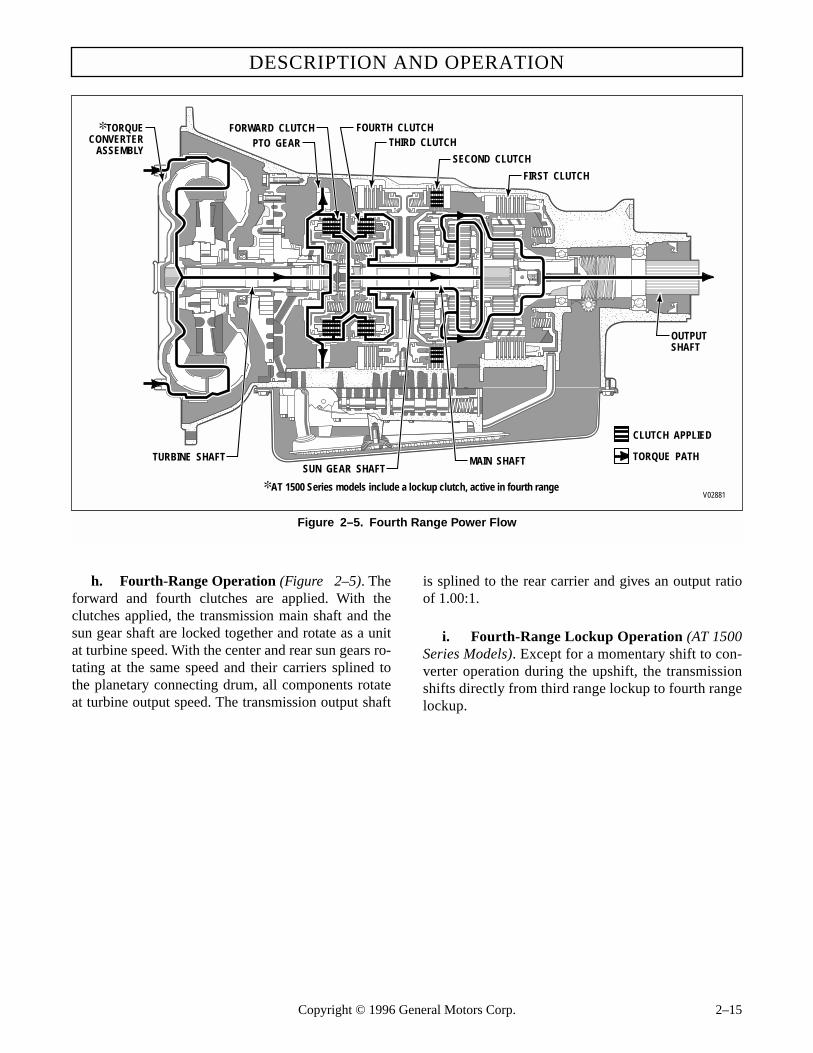
DESCRIPTION AND OPERATION
Figure 2–5. Fourth Range Power Flow
������������
������������
��
����
��
�� ��
��������������������������������������������������������������������������������
��
����
����
������
�� �
��
����
���������
������
����
�������
���
���
������������������������������������
���������
��������
���
� �
�
�
�
����
����
����
��
��
����
�����������
�
��
����
����
��
V02881
TURBINE SHAFTSUN GEAR SHAFT
PTO GEARFORWARD CLUTCH
THIRD CLUTCH
SECOND CLUTCH
FIRST CLUTCH
FOURTH CLUTCH✽ TORQUECONVERTER
ASSEMBLY
MAIN SHAFT TORQUE PATH
✽ AT 1500 Series models include a lockup clutch, active in fourth range
CLUTCH APPLIED
OUTPUTSHAFT
h. Fourth-Range Operation (Figure 2–5). Theforward and fourth clutches are applied. With theclutches applied, the transmission main shaft and thesun gear shaft are locked together and rotate as a unitat turbine speed. With the center and rear sun gears ro-tating at the same speed and their carriers splined tothe planetary connecting drum, all components rotateat turbine output speed. The transmission output shaft
is splined to the rear carrier and gives an output ratioof 1.00:1.
i. Fourth-Range Lockup Operation (AT 1500Series Models). Except for a momentary shift to con-verter operation during the upshift, the transmissionshifts directly from third range lockup to fourth rangelockup.
Copyright © 1996 General Motors Corp. 2–15

AT 500, 1500 SERIES AUTOMATIC TRANSMISSIONS
Figure 2–6. Reverse Power Flow
������������
������������
��
����
��
�� ��
��������������������������������������������������������������������������������
��
����
����
������
�� �
��
����
���������
������
����
�������
���
���
������������������������������������
���������
��������
���
� �
�
�
�
����
����
����
��
��
����
�����������
�
��
����
����
��
V02882
TURBINE SHAFTSUN GEAR SHAFT
PTO GEARFORWARD CLUTCH
THIRD CLUTCH
SECOND CLUTCH
FIRST CLUTCH
FOURTH CLUTCH✽ TORQUECONVERTER
ASSEMBLY
MAIN SHAFT TORQUE PATH
✽ AT 1500 Series models include a lockup clutch, not active in reverse
CLUTCH APPLIED
OUTPUTSHAFT
j. Reverse Operation (Figure 2–6). Reverse isthe only range in which the forward clutch is not en-gaged. In this range, the fourth clutch is applied andthis rotates the sun gear shaft assembly (with the frontand center sun gears splined to it) at turbine speed. Thefirst clutch is applied also, and anchors the rear ringgear against rotation. The center sun gear rotates thecenter carrier pinions, which, in turn, rotate the centerring gear in an opposite direction. The center carrier is
splined to the planetary connecting drum, which issplined to the rear carrier. The reverse direction of ro-tation of the center ring gear rotates the rear sun gear.This causes the rear planetary pinions to drive the rearcarrier, in a reverse direction, within the stationaryring gear. This compounding action of the center andrear planetaries produces a reverse rotation output ra-tio of 5.02:1.
2–16 Copyright © 1996 General Motors Corp.

Section 3 – PREVENTIVE MAINTENANCE
3–1. SCOPE
(1) This section outlines the routine and pe-riodical procedures required to maintain the transmis-sion in good operating condition.
(2) For transmission removal and installationguidelines, engine adaptation hardware specifications,and road test checks, refer to the AT Mechanic’s Tips,SA1321.
3–2. PERIODIC INSPECTIONAND CARE
a. Clean and inspect the exterior of the transmis-sion at regular intervals. The severity of service andoperating conditions will determine the frequency ofsuch inspections. Inspect the transmission for:
• loose bolts (transmission and mounting components)
• transmission fluid leaks*
• shift linkage freely positioned by transmis-sion detent
• full (and ease of) movement of mechanical modulator linkage
• vacuum or air line and modulator for leaks
• damaged or loose hydraulic lines
• worn or frayed electrical connections
• driveline U-joints and slip fittings
• speedometer cable and fittings
• PTO linkage and driveline
b. Check the transmission hydraulic level at theintervals specified in the vehicle operator manual.
3–3. IMPORTANCE OF PROPER TRANSMISSION FLUID LEVEL
a. Effects of Improper Fluid Level. Becausethe transmission fluid cools, lubricates, and transmits
hydraulic power, it is important that the proper fluidlevel be maintained at all times. If the fluid level is toolow, the converter and clutches will not receive an ade-quate supply of fluid. If the level is too high, the fluidwill aerate, the transmission will overheat, and fluidmay be expelled through the breather or dipstick tube.
b. Foaming and Aerating
(1) Transmission performance will be af-fected when the fluid foams or aerates. The primarycause of aeration is low fluid in the sump, too muchfluid in the sump, or a defective or missing sealring onthe intake tube.
(2) A low fluid level (denoted on the dip-stick) will not completely envelop the fluid filter.Therefore fluid and air are drawn in by the input pumpand directed to the clutches and converter, causingconverter cavitational noises and irregular shifting.The aeration also changes the viscosity and color ofthe fluid to a thin milky liquid.
(3) At normal fluid level, the fluid is slightlybelow the planetary gear units. If the transmission isoverfilled, the planetary units will run in the fluid,causing it to become aerated. Overheating and irregu-lar shift patterns can occur when the fluid is aerated.
(4) A defective sealring 20, 37, or 45 (Fold-out 12,B) on the filter intake tube will cause the inputpump to draw air and fluid from the sump, causing thefluid to become aerated.
3–4. DIPSTICK MARKINGS
Three dipstick variations are available for use with theAT 500 and 1500 Series transmissions. The dipstickwill have markings similar to those seen in Figure 3–1,3–2, or 3–3. Variations in fill tube placement and dip-stick orientation may change these dimensionsslightly.
Copyright © 1996 General Motors Corp. 3–1
* Transmission fluid leaks require immediate attention.

AT 500, 1500 SERIES AUTOMATIC TRANSMISSIONS
Figure 3–1. Dipstick With FULL and ADD Markings
Figure 3–2. Dipstick With HOT RUN Markings
Figure 3–3. Dipstick With HOT OVERFULL Markings
3–5. TRANSMISSION FLUID LEVEL CHECK PROCEDURE
a. Preparation
(1) Always check the transmission fluidlevel at least twice. Consistency is important in main-taining accuracy. If inconsistent readings persist,check the transmission breather and the vent hole inthe dipstick fill tube to ensure they are clean and freeof debris. The vent hole is located on the underside ofthe fill tube just below the seal of the dipstick cap.
(2) Clean around the end of the fill tube be-fore removing the dipstick. Dirt or foreign matter mustnot be permitted to enter the transmission because itcan cause valves to stick, cause undue wear of trans-
TRANSMISSIONOIL PANSPLITLINE
FULL
ADD
0.50 in.(12.7 mm)
1.00 in.(25.4 mm)
V01299
CHECK IN NEUTRAL AT IDLE
TRANSMISSIONOIL PANSPLITLINE
0.50 in.(12.7 mm)
1.05 in.(26.7 mm)
1.80 in.(45.7 mm)
1.50 in.(38.1 mm)
V01298
CHECK IN NEUTRAL AT IDLE
HOT RUN
REFFILL
WARNING!
When checking the transmission fluid level, be surethat the parking brake and/or emergency brakesare set and properly engaged, and the wheels areblocked. Unexpected and possible sudden move-ment may occur if these precautions are not taken.
TRANSMISSIONOIL PANSPLITLINE
TRANSMISSIONOIL PANSPLITLINE
0.50 in.(12.7 mm)
1.50 in.(38.1 mm)
SHALLOW PANMODELS
DEEP PANMODELS
2.00 in.(50.8 mm)
V01300
CHECK IN NEUTRAL AT IDLE
OVER
FULL
HOT
COLD
RUN
OVER
FULL
CHECK IN NEUTRAL AT IDLE
COLD
RUN
HOT
0.50 in.(12.7 mm)
1.75 in.(44.5 mm)
2.25 in.(57.1 mm)
3–2 Copyright © 1996 General Motors Corp.

PREVENTIVE MAINTENANCE
PREVENTIVE MAINTENANCE
mission parts, or clog passages. Check the fluid levelby the following procedures and record any abnormallevel on your maintenance records.
b. Cold Check
NOTE:• A Cold Check is performed with dipsticks sim-
ilar to those illustrated in Figure 3–2 and 3–3.• The fluid level rises as sump temperature in-
creases. DO NOT FILL above the REF FILL(COLD RUN) band if the transmission fluid isbelow normal operating temperature.
(1) Park the vehicle on a level surface, applythe parking brake, and block the wheels.
(2) Run the engine at 1000–1500 rpm forone minute to purge air from the system. Allow theengine to idle. Shift to D (Drive) and then to R (Re-verse) to fill the hydraulic circuits with fluid. Then,shift to N (Neutral) or P (Park). The sump tempera-ture should be 60–120°F (16–50°C).
(3) After wiping the dipstick clean, checkthe fluid level. If the fluid level is within the REF FILL(COLD RUN) band (Figures 3–2, 3–3), the level issatisfactory for operating the transmission until thefluid is hot enough to perform a Hot Check. If the fluidlevel is not within these parameters, raise or lower thefluid level to bring it within the band.
(4) Perform a Hot Check at the first opportu-nity after normal operating temperature is reached(160–200°F (71–93°C) sump temperature; 180–220°F(82–104°C) converter-out temperature).
c. Hot Check
NOTE:A Hot Check is performed with all dipstick designs(Figures 3–1 through 3–3).
(1) Operate the transmission until normal op-erating temperature is reached (160–200°F (71–93°C)sump temperature; 180–220°F (82–104°C) converter-out temperature). Shift to D (Drive) and then to R (Re-verse) to fill the hydraulic circuits with fluid.
(2) Park the vehicle on a level surface andshift to N (Neutral) or P (Park). Apply the parkingbrake, block the wheels, and allow the engine to idle.
Copyright © 1996 Gen
eral Motors Corp. 3–3(3) After wiping the dipstick clean, checkthe fluid level. The safe operating level is anywherebetween the FULL and ADD lines (Figure 3–1),within the HOT RUN band (Figure 3–2), or below theHOT OVERFULL mark and above the COLD RUNband (Figure 3–3).
(4) If the fluid level is outside of these pa-rameters, raise or lower the fluid level to bring itwithin the correct markings on the dipstick.
3–6. KEEPING TRANSMISSIONFLUID CLEAN
Transmission fluid must be handled in clean containersto prevent foreign material from entering the transmis-sion. Lay the dipstick in a clean place while filling thetransmission.
3–7. TRANSMISSION FLUID RECOMMENDATIONS
a. Recommended Automatic Transmission Fluid and Viscosity Grade
(1) Hydraulic fluids (oils) used in the transmis-sion are important influences on transmission perfor-mance, reliability, and durability. Use DEXRON®-III flu-ids for standard duty, highway applications. Use C-4fluids for severe duty and off-highway applications.
(2) Some DEXRON®-III fluids are alsoqualified as C-4 fluids. To ensure the fluid is qualifiedfor use in Allison Transmissions, check for aDEXRON®-III or C-4 fluid license, or approval num-bers on the container, or consult the lubricant manu-facturer. Consult your Allison Transmission dealer ordistributor before using other fluid types; fluid typessuch as Type F, and universal farm fluids may or maynot be properly qualified for use in your Allison trans-mission.
CAUTION:
Containers or fillers that have been used to han-dle antifreeze or engine coolant solution mustnever be used for transmission fluid. Antifreezeand coolant solutions contain ethylene glycolwhich, if introduced into the transmission, cancause the clutch plates to fail.

AT 500, 1500 SERIES AUTOMATIC TRANSMISSIONS
(3) When choosing the optimum viscositygrade of fluid to use, duty cycle, preheat capabilities,and/or geographical location must be taken into consid-eration. Table 3–1 lists the minimum fluid temperaturesat which the transmission may be safely operated. Pre-heat with auxiliary heating equipment or by runningthe vehicle with the transmission in neutral for a mini-mum of 20 minutes before attempting range operation.
3–8. TRANSMISSION FLUID AND FILTER CHANGE INTERVALS
Transmission fluid and filter change frequency is de-termined by the severity of transmission service andby the filter equipment installed. Table 3–2 is a gen-eral guide. More frequent changes may be requiredwhen the fluid is visually contaminated, when opera-tions are subject to high levels of contamination oroverheating, or if it is determined by fluid analysisthat the fluid is oxidized beyond the limits listed inTable 3–3.
3–9. TRANSMISSION FLUID CONTAMINATION
a. Examine at Fluid Change. At each fluidchange, examine the fluid which is drained for evi-dence of dirt or engine coolant (water). A normalamount of condensation will emulsify in the fluid dur-ing operation of the transmission. However, if there is
evidence of coolant, check the cooler (heat exchanger)for leakage between the coolant and fluid areas. Fluidin the coolant side of the cooler (heat exchanger) is an-other sign of leakage. This, however, may indicateleakage from the engine oil system.
b. Metal Particles. Metal particles in the fluid(except for the minute particles normally trapped inthe filter) indicate damage has occurred in the trans-mission. When these particles are found in the sump,the transmission must be disassembled and closely in-spected to find the source. Metal contamination willrequire complete disassembly of the transmission andcleaning of all internal and external circuits, cooler,and all other areas where the particles could lodge.(See application of auxiliary filter, Paragraph 3–9d.)
c. Coolant Leakage. If engine coolant leaks intothe transmission hydraulic system, immediate actionmust be taken to prevent malfunction and possible se-rious damage. The transmission must be completelydisassembled, inspected, and cleaned. All traces of thecoolant, and varnish deposits resulting from coolantcontamination must be removed. Clutch plates con-taminated with ethylene glycol must be replaced.
d. Auxiliary Filter (Figure 3–4)
(1) If a condition occurs that introduces de-bris into the hydraulic system, completely clean-up thecooler and lines.
(2) However, repeated cleaning and flushingmay not remove all debris. For models with retarder,replace the main cooler; for models without retarder,installation of an auxiliary filter in the cooler-out line(between cooler and transmission) is required if such afilter does not already exist. This requirement applieswhether the transmission is overhauled or replaced bya new or rebuilt unit.
CAUTION:
Disregarding minimum fluid temperature limitscan result in transmission malfunction or re-duced transmission life.
Table 3–1. Operating Temperature Requirementsfor Transmission Fluid
(Ambient Temperature Below Which Preheat Is Required)
Viscosity Grade Fahrenheit Celsius
SAE 0W-20 –31 –35
DEXRON®-III –17 –27
SAE 10W –4 –20
SAE 15W-40 5 –15
SAE 30 32 0
SAE 40 50 10
(Ref. 13-TR-90.)
CAUTION:
If excessive metal contamination has occurred, re-placement of the cooler and replacement of allbearings within the transmission is recommended.
CAUTION:
For retarder models, do not add an additionalauxiliary filter after a debris-causing condition.
3–4 Copyright © 1996 General Motors Corp.

PREVENTIVE MAINTENANCE
PREVENTIVE MAINTENANCE
Table 3–2. Transmission Fluid and Filter Change Intervals
TransmissionApplication
Fluid ChangeInternal Sump andGovernor Filters
ExternalAuxiliary Filter**
AT 500 Series (On-Highway) (Light-duty)
Paper Filter: 25,000 miles (40 000 km)or 12 months*
Paper Filter in Shallow Pan (4.0 inches) or Deep Pan (5.3 inches):
25,000 miles (40 000 km)or 12 months*
After first 5000 miles(8 000 km) and at 25,000 miles (40 000 km) or 12 months*, thereafter
(School Bus, NA Motorhome and One-Way Rental)
Brass Filter: 50,000 miles (80 000 km)or 24 months*
Brass Screen Filter in Shallow Pan(4.0 inches) or Deep Pan (5.3 inches):
50,000 miles (80 000 km) with no time limit
AT 500 Series(On-Highway) (Heavy-duty) (Models With Retarder)
25,000 miles (40 000 km)or 12 months*
Paper Filter in Shallow Pan (4.0 inches) or Deep Pan (5.3 inches):
25,000 miles (40 000 km) or12 months*
After first 5000 miles(8 000 km) and at normal fluid change intervals thereafter
Brass Screen Filter in Shallow Pan (4.0 inches) or Deep Pan (5.3 inches):
50,000 miles (80 000 km) with no time limit
AT 500 Series (Off-Highway)
1000 hours max or 12 months* Paper Filter in Shallow Pan (4.0 inches) or Deep Pan (5.3 inches):
at each fluid change interval
After first 500 hours, and at normal fluid change intervals, thereafter
Brass Screen Filter in Shallow Pan(4.0 inches) or Deep Pan (5.3 inches):
at each fluid change interval
* Whichever occurs first.
** An Allison high-efficiency oil filter may be used until the Change Filter light indicates it is contaminated or until it has been in use for three years, whichever occurs first. No mileage restrictions apply.
Table 3–3. Fluid Oxidation Measurement Limits
Measurement Limit
Viscosity ±25% change from new fluid
Carbonyl absorbance + 0.3 A*/0.1 mm change from new fluid
Total acid number + 3.0 change from new fluid
Solids 2% by volume maximum
*A = Absorbance units
Refer to SIL 17-TR-83 for fluid analysis techniques and data interpretation.
Consult your local industrial yellow pages for fluid analysis firms. Use one fluid analysis firm.Results between firms cannot be accurately compared.
Copyright © 1996 General Motors Corp. 3–5

AT 500, 1500 SERIES AUTOMATIC TRANSMISSIONS
Figure 3–4. Installation of Auxiliary Filter (Models Without Retarder)
FROM COOLER
TO COOLER
TRANSMISSION
ENGINE
RADIATOR
AUXILIARYFILTER
TRANSMISSION FLUID TO COOLER
TRANSMISSION FLUIDFROM COOLER
COO
LANT
COO
LANT
NAMEPLATE
V03129
TYPICAL COOLER
(3) If any doubt exists about the clean-up ofthe cooler, replace the cooler.
(4) The auxiliary filter must have a 40 mi-cron filter element and a maximum filter pressuredrop of 3 psi (21 kPa) at 4.5 gal/min (17 l/min) at180–200°F (82–93°C). The maximum external circuitpressure drop must not exceed 35 psi (241 kPa) at 4.5gal/min (17 l/min) at 180–200°F (82–93°C).
(5) Use one of the following recommendedauxiliary filters:
(6) Install the filter into the line from thecooler to the transmission. Use a hose long enough toallow power pack movement. Proper hose size willpermit a minimum flow rate of 4.5 gal/min (17 l/min).The hose must have a burst pressure of not less than200 psi (1379 kPa), and a minimum inside diameter atfittings of 0.391 inch (9.93 mm). The hose must meetSAE 100 R5 specification, with an operating range of–40 to +300°F (–40 to 149°C).
(7) The total cooler circuit (to and from thecooler) pressure drop must not exceed 35 psi (241kPa) in neutral, at 2400 rpm and at normal operatingtemperature. Filter bypass opening pressure on unitsnot equipped with a pressure indicator (∆P switch)must be 5–9 psi (34–62 kPa). Filter bypass openingpressure on units equipped with a 5.5–8.5 psi (38–59kPa) pressure indicator (∆P switch) must be 10.5–13.5psi (72–93 kPa).
(8) External auxiliary filter element change in-tervals can be determined according to Paragraph 3–8.
Filter Assembly Filter ElementAllison 29501482* Allison 29510922*
AC PM 13-16 PF 897
AC PM 16-1 PF 141
Fram HP 1-1 HP 1
Purolator OF-15C-1 OF-2C-1
Purolator PER-20-10 PER-20
* high efficiency
3–6 Copyright © 1996 General Motors Corp.

eneral Motors Corp. 3–7
PREVENTIVE MAINTENANCE
PREVENTIVE MAINTENANCE
Copyright © 1996 G
3–10. TRANSMISSION FLUID AND FILTER CHANGE PROCEDURES
a. Disassembly (Foldout 12,B)
(1) The transmission should be at operatingtemperature to assist draining. Shift the transmissionto N (Neutral) or P (Park) and turn off the engine.
(2) Drain the transmission fluid by removingthe drain plug and washer and disconnecting the filltube from the oil pan.
(3) Remove twenty-one washer-head screws28 or 31 that retain oil pan 26 or 33 to the transmissionhousing. Discard pan gasket 22, 39, or 47. Clean pan26 or 33 with mineral spirits.
(4) Remove the screw or bolt and washerthat retains internal filter assembly 21, 38, or 46. Re-move the filter and intake tube 18, 40, or 48. Removesealring 20, 37, or 45 and discard.
(5) Clean or replace governor circuit screen12. The screen is located in the governor feed tubebore. Replacement of the screen can only be accom-plished by removing governor feed tube 13. This tubeand the two remaining tubes are held in place by themain control valve body. Refer to Paragraph 5–3h formain control valve body removal procedures and Para-graph 7–10a for main control valve body installation.
b. Assembly (Foldout 12,B)
(1) Install a new sealring onto the top end ofthe intake tube. Lubricate the sealring with transmis-sion fluid.
(2) Insert the intake tube and sealring intothe hole in the bottom of the transmission. Install newfilter assembly 21, 38, or 46 (including grommet) ontothe intake tube.
(3) If deep pan 33 is used, retain the filter(earlier models) with one 5⁄16-18 x 21⁄4 inch bolt andone 5⁄16 inch washer. For later models with high-capac-ity filter, install the 5⁄16-18 x 5⁄8 inch washer-headscrew. If shallow pan 26 is used, retain the filter withone 5⁄16-18 x 5⁄8 inch washer-head screw. Tighten eitherthe screw or the bolt to 10–15 lb ft (14–20 N·m).
(4) Place the pan gasket onto the oil pan. Donot use any substance as a gasket retainer.
(5) Install the oil pan. Guide the pan andgasket carefully into place. Guard against dirt or for-eign material entering the pan. Retain the pan to thehousing with four 5⁄16-18 washer-head screws, in-stalled by hand into the corners of the pan.
(6) Install the remaining seventeen washer-head screws by hand, carefully threading eachthrough the gasket and into the transmission. Bottomall of the screws before tightening any of them.
(7) Evenly tighten all twenty-one screws to10–15 lb ft (14–20 N·m). Check gasket fit while thescrews are being tightened.
(8) Install the filler tube at the side of thepan.
(9) Check Dimension A (Figure 3–5) to de-termine what oil pan boss is present. If Dimension A is0.570–0.580 inch (14.48–14.73 mm), then tighten thetube fitting to 65–75 lb ft (88–102 N·m); if DimensionA is 0.670–0.680 inch (17.02–17.27 mm), then tightenthe tube fitting to 90–100 lb ft (122–136 N·m).
(10) Install the drain plug and washer. Tightenthe plug to 15–20 lb ft (20–27 N·m).
(11) Replace the external auxiliary filter ele-ment (cooler-out line), if present. Refer to Paragraph3–9d.
(12) Refill the transmission with fluid.
(13) Check the fluid level as outlined in Para-graph 3–5.
CAUTION:
Do not use gasket-type sealing compounds, fi-brous greases, or nonsoluble, vegetable-basecooking compounds any place inside the trans-mission or where they could be flushed into thetransmission hydraulic system.
Fluid Fill Rebuild Servicing
Shallow oil pan — 4.0 inch (102 mm)
15 U.S. qts. (14 liters)
9 U.S. qts. (8.5 liters)
Deep oil pan — 5.3 inch (135 mm)
22 U.S. qts. (21 liters)
16 U.S. qts. (15 liters)

AT 500, 1500 SERIES AUTOMATIC TRANSMISSIONS
(14) Refer to Table 3–2 and determine whenthe next fluid and filter changes will be required. If la-bels are available (Figure 3–6), fill in the appropriatedates and affix the labels in a conspicuous location inthe vehicle.
3–11. BREATHER
(1) The breather is located at the top of thetransmission housing. It serves to prevent pressurebuildup within the transmission and must be kept
clean and the passage open. The prevalence of dustand dirt will determine the frequency at which thebreather requires cleaning. Use care when cleaning thetransmission. Spraying steam, water, or cleaning solu-tion directly at the breather can force the water or solu-tion into the transmission.
(2) Earlier model breathers should beequipped with a neoprene shroud (Figure 3–7). If thebreather is not so equipped or if the present shroud isdamaged, install a new shroud.
Figure 3–5. Measuring the Length of Oil Pan Boss to Identify Torque Requirements
Figure 3–6. Fluid and Filter Change Reminder Labels
A
Dimension A0.570–0.580 in. (14.48–14.73 mm)0.670–0.680 in. (17.02–17.27 mm)
NOTE: Except for Dimension A, the oil pan in Figure 3–5 does not represent all AT oil pan configurations.
Torque Specifications65 –75 lb ft (88–102 N·m)90 –100 lb ft (122–136 N·m)
V03098
Next TransmissionFluid Change is Due
Allison Transmission
Miles/kmorDate
Next Transmission InternalFilter Change is Due
Allison Transmission
Miles/km
V02883
3–8 Copyright © 1996 General Motors Corp.

PREVENTIVE MAINTENANCE
PREVENTIVE MAINTENANCE
Figure 3–7. Breather Configurations
3–12. LINKAGE
a. Shift Selector Lever and Control Linkage
(1) To install the shift selector lever and nut,refer to the latest edition of the AT Mechanic’s Tips,SA1321.
(2) Proper adjustment of the shift selectorcontrol linkage is important as the shift selector de-tents must correspond exactly to those in the transmis-sion. Periodic inspections should be made for bent orworn parts, loose threaded connections, loose bolts,and accumulation of grease and dirt. All moving jointsmust be kept clean and well lubricated. For connectingand adjusting the shift selector control linkage, refer tothe latest edition of the AT Mechanic’s Tips, SA1321.
b. Mechanical Actuator Adjustment. It is im-perative the mechanical linkage be properly adjustedfor efficient performance. For installing and adjustingthe mechanical modulator control, refer to the latestedition of the AT Mechanic’s Tips, SA1321.
c. Other Linkage Adjustments. For adjust-ments to other linkage, such as PTO, speedometer,etc., refer to the latest edition of the AT Mechanic’sTips, SA1321.
3–13. ADJUSTMENT OF SHIFT POINTS
NOTE:Transmission shift points cannot be satisfactorilyadjusted if the transmission has the wrong governorinstalled. Check the three-digit code on the head ofthe governor with the code shown in the AllisonParts Catalog (SA1235) for the governor listed foryour transmission assembly part number. If the let-ter “M” follows the three-digit code, the governor isa service replacement assembly. If the “M” is not in-cluded, the governor was installed at original factorybuild.
a. Calibrated on Test Stand or in Vehicle
(1) Proper timing of shift speed points isnecessary for maximum transmission performance.Shifts may be adjusted on the test stand when thetransmission is rebuilt or overhauled, or during roadtesting of the vehicle.
(2) The Kent Moore Valve and GovernorTest Stand (J 25000-1) with adapter J 25000-225 orAidco (Model 250) is designed to check five principaltransmission functions. It performs a checking proce-dure on the governor, modulator, hold regulator, shiftpoints (up-down-inhibit), and a trimmer regulatorcheck. If a test stand is not available, satisfactory cali-bration of shift points may be made after road testingof the vehicle.
b. Location of Adjusting Components
(1) Shift points are changed by changing thepositions of adjusting rings that determine the retain-ing force of valve springs in the main control valvebody. Refer to items 4 or 82, and 51, 58, 64, and 70 onFoldout 11.
(2) Special tool J 24314 is used to depressand rotate the adjusting rings. Clockwise rotation in-creases spring force and raises the shift point; counter-clockwise rotation reduces spring force and lowers theshift point.
NOTE:Each notch of adjustment alters the shift point ap-proximately 40 output shaft rpm or 2 mph (mphwill vary based on axle ratio and tire size).
CAUTION:
Manual selector shafts that are center drilled attheir outer ends require an M10 x 1.5-6G nut(metric thread). Shafts that are undrilled requirea 3⁄8-16 nut (standard inch series). Use of thewrong nut will damage both the shaft and nut.Torque for either nut is 15–20 lb ft (20–27 N·m).
V02884
LATER MODELSEARLIER MODELS
NEOPRENE SHROUD
Copyright © 1996 General Motors Corp. 3–9
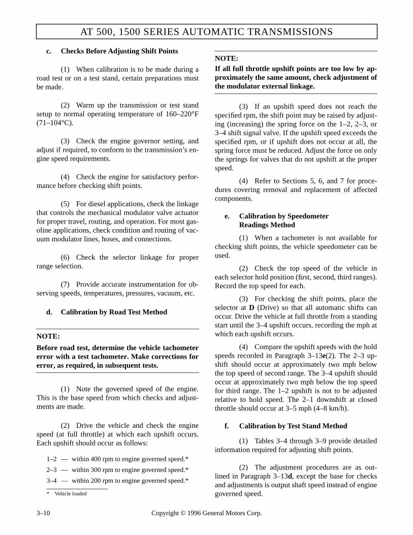
AT 500, 1500 SERIES AUTOMATIC TRANSMISSIONS
c. Checks Before Adjusting Shift Points
(1) When calibration is to be made during aroad test or on a test stand, certain preparations mustbe made.
(2) Warm up the transmission or test standsetup to normal operating temperature of 160–220°F(71–104°C).
(3) Check the engine governor setting, andadjust if required, to conform to the transmission’s en-gine speed requirements.
(4) Check the engine for satisfactory perfor-mance before checking shift points.
(5) For diesel applications, check the linkagethat controls the mechanical modulator valve actuatorfor proper travel, routing, and operation. For most gas-oline applications, check condition and routing of vac-uum modulator lines, hoses, and connections.
(6) Check the selector linkage for properrange selection.
(7) Provide accurate instrumentation for ob-serving speeds, temperatures, pressures, vacuum, etc.
d. Calibration by Road Test Method
NOTE:
Before road test, determine the vehicle tachometererror with a test tachometer. Make corrections forerror, as required, in subsequent tests.
(1) Note the governed speed of the engine.This is the base speed from which checks and adjust-ments are made.
(2) Drive the vehicle and check the enginespeed (at full throttle) at which each upshift occurs.Each upshift should occur as follows:
NOTE:If all full throttle upshift points are too low by ap-proximately the same amount, check adjustment ofthe modulator external linkage.
(3) If an upshift speed does not reach thespecified rpm, the shift point may be raised by adjust-ing (increasing) the spring force on the 1–2, 2–3, or3–4 shift signal valve. If the upshift speed exceeds thespecified rpm, or if upshift does not occur at all, thespring force must be reduced. Adjust the force on onlythe springs for valves that do not upshift at the properspeed.
(4) Refer to Sections 5, 6, and 7 for proce-dures covering removal and replacement of affectedcomponents.
e. Calibration by SpeedometerReadings Method
(1) When a tachometer is not available forchecking shift points, the vehicle speedometer can beused.
(2) Check the top speed of the vehicle ineach selector hold position (first, second, third ranges).Record the top speed for each.
(3) For checking the shift points, place theselector at D (Drive) so that all automatic shifts canoccur. Drive the vehicle at full throttle from a standingstart until the 3–4 upshift occurs, recording the mph atwhich each upshift occurs.
(4) Compare the upshift speeds with the holdspeeds recorded in Paragraph 3–13e(2). The 2–3 up-shift should occur at approximately two mph belowthe top speed of second range. The 3–4 upshift shouldoccur at approximately two mph below the top speedfor third range. The 1–2 upshift is not to be adjustedrelative to hold speed. The 2–1 downshift at closedthrottle should occur at 3–5 mph (4–8 km/h).
f. Calibration by Test Stand Method
(1) Tables 3–4 through 3–9 provide detailedinformation required for adjusting shift points.
(2) The adjustment procedures are as out-lined in Paragraph 3–13d, except the base for checksand adjustments is output shaft speed instead of enginegoverned speed.
1–2 — within 400 rpm to engine governed speed.*
2–3 — within 300 rpm to engine governed speed.*
3–4 — within 200 rpm to engine governed speed.*
* Vehicle loaded
3–10 Copyright © 1996 General Motors Corp.

PREVENTIVE MAINTENANCE
PREVENTIVE MAINTENANCE
Table 3–4. Hold Regulator Pressure
rpmValve Body
PressureSpring No. Color Code psi kPa
2400 6836785 White 39–43 269–296
2600 6837952 Green 44–48 303–331
2600/3000 Hold 6836977 Orange 44–48 303–331
2700/2800 Hold 6837953 Blue 46–50 317–345
2800 6837953 Blue 46–50 317–345
2800/3200 Hold 6837952 Green 44–48 303–331
3000 6836976 White With Yellow Stripe 42–46 290–317
3200 6837952 Green 44–48 303–331
3400 6837953 Blue 46–50 317–345
3600 6836784 Yellow 36–40 248–276
3800 6836785 White 39–43 269–296
4000 6836785 White 39–43 269–296
Table 3–5. Modulator Pressure
Modulator SpringPart Number
Color Code andModulator Valve Usage
Pressurepsi kPa
23012948 White with Orange Stripe23013764 Modulator Valve
50–53 345–365
6880980 Solid Light Blue with Red Stripe23013764 Modulator Valve
42–45 290–310
Table 3–6. Governor Pressure
GovernorAssemblies
Code Number 440rpm
800rpm
1500rpm
2200rpm
6881466 460 (Old Code 91) 7–10(48–69)
21.5–24.5(148–169)
38.0–42.5(265–293)
55.5–63.0(383–434)
6885570 461 (Old Code 54) 9–13(62–90)
38–42(262–290)
64.0–70.0(441–483)
103–112(710–772)
6885571 462 (Old Code 52) 8.5–11.5(59–79)
27.5–30.5(190–210)
54.5–61.0(376–421)
82.6–91(570–627)
Copyright © 1996 General Motors Corp. 3–11

3–12C
opyright © 1996 G
eneral Motors C
orp.
AT
500, 1500 SE
RIE
S A
UT
OM
AT
IC T
RA
NS
MIS
SIO
1 Prior to S/N 3210279820.
2 S/N 3210279820 thru 3210302450.
* For 2nd range start, check for manual shift function only.
** For no 4th range, this shift should not occur.
+ 4–2 downshift is acceptable.
Full throttle position is 0 inch (0 mm) Hg vacuum.
Closed throttle position is 19–21 inch (483–533 mm) Hg vacuum.
Notice: To update units prior to S/N 3210302450 to later configuration, refer to SIL 14-TR-85.
Table 3–7. AT 500 Shift Points — Models With S/N 3210302450 and Before(Without Lockup)
Engine Governed Speed — rpm 2400 2400 2600 2800 3000 3200 3400 3600 3800/4000
AT 545 Parts Catalog Valve Body Group J1 J2 G F E D B A C
RangeThrottle Position Shift
Transmission Output Speed (rpm) at Start of Shift
1–2* 580–640 580–640 595–655 595–655 710–770 770–830 770–830 900–960 900–960
Full 2–3 865–1000 865–1000 955–1090 1045–1180 1130–1265 1220–1355 1310–1445 1400–1535 1490–1625
Drive 3–4** 1455–1595 1455–1595 1595–1735 1735–1875 1880–2020 2020–2160 2165–2305 2305–2445 2450–2590
4–3**+ 305–555 370–660 350–610 490–685 410–680 530–750 675–970 150–600 300–700
Closed 3–2+ 400–560 475–655 465–630 520–665 550–760 590–810 620–875 405–720 455–765
2–1* 20–300 20–360 20–300 20–300 20–300 20–450 20–450 50–450 50–450
DR3 4–3** 1820–2120 1820–2120 1980–2280 2100–2370 2240–2690 2290–2770 2400–2890 2600–3050 2760–3240
DR2 Full 3–2 1060–1350 1060–1350 1200–1470 1270–1530 1330–1700 1380–1740 1470–1850 1570–1990 1700–2130
DR1 2–1* 660–900 660–900 735–970 770–1010 910–1080 930–1100 960–1200 900–1340 1000–1450
Modulator Pressurepsi (kPa)
50–53(345–365)
42–45(290–310)
50–53(345–365)
50–53(345–365)
50–53(345–365)
50–53(345–365)
50–53(345–365)
50–53(345–365)
50–53(345–365)
Hold Regulator Pressurepsi (kPa)
39–43(269–296)
39–43(270–296)
44–48(303–331)
46–50(317–345)
42–46(290–317)
44–48(303–331)
46–50(317–345)
36–40(248–276)
39–43(269–296)
NS

Copyright ©
1996 General M
otors Corp.
3–13
PRE
VE
NT
IVE
MA
INT
EN
AN
CE
PR
EV
EN
TIV
E M
AIN
TE
NA
NC
E
* For 2nd range start, check for manual shift function only.
** For no 4th range, this shift should not occur.
+ 4–2 downshift is acceptable.
Full throttle position is 0 inch (0 mm) Hg vacuum.
Closed throttle position is 19–21 inch (483–533 mm) Hg vacuum.
Notice: To update units prior to S/N 3210302450 to later configuration, refer to SIL 14-TR-85.
Table 3–8. AT 500 Shift Points — Models After S/N 3210302450(Without Lockup)
Engine GovernedSpeed — rpm
2400 2600 2800 3000 3200 3400 3600 3800 4000
AT 545 Parts Catalog Valve Body Group
J, R U G, M P F, H, K, L E, N, S V D B A C, Q T
AT 542 Parts Catalog Valve Body Group
B, Q F, J E N C K D M G H A, P L
RangeThrottlePosition Shift
Transmission Output Speed (rpm) at Start of Shift
1–2* 580-640 580-640 595-655 595-655 595-655 625-680 710-770 595-655 770-830 650-710 770-830 900-960 970-1030 980-1045
Full 2–3 865-1000 970-1090 955-1090 955-1180 1045-1180 1000-1135 1130-1265 955-1090 1220-1355 1045-1180 1310-1445 1400-1535 1490-1625 1600-1700
Drive 3–4** 1455-1595 1455-1595 1595-1735 1595-1735 1735-1875 1665-1810 1880-2020 1595-1735 2020-2160 1740-1880 2165-2305 2305-2445 2450-2590 2555-2710
4–3**+ 510-740 510-740 550-780 670-970 670-990 600-810 600-970 550-780 700-1100 500-795 850-1370 150-600 300-700 200-765
Closed 3–2+ 400-610 435-620 460-650 610-750 510-680 485-645 500-730 460-650 580-820 395-660 610-880 405-720 455-765 445-700
2–1* 40-370 40-370 40-370 220-500 40-370 50-375 140-460 40-370 230-500 40-295 230-500 50-450 50-450 75-480
DR3 4–3** 1820-2120 1820-2120 1980-2280 1980-2280 2100-2370 2100-2370 2240-2690 2150-2475 2290-2770 2290-2770 2400-2890 2600-3050 2760-3240 2760-3240
DR2 Full 3–2 1060-1350 1060-1350 1200-1470 1200-1470 1270-1530 1270-1530 1330-1700 1325-1580 1380-1740 1380-1740 1470-1850 1570-1990 1700-2130 1700-2130
DR1 2–1* 660-900 660-900 735-970 735-970 770-1010 770-1010 910-1080 805-1095 930-1100 930-1100 960-1200 900-1340 1000-1450 1000-1450
Modulator Pressurepsi (kPa)
50-53(345-365)
50-53(345-365)
50-53(345-365)
50-53(345-365)
50-53(345-365)
50-53(345-365)
50-53(345-365)
50-53(345-365)
50-53(345-365)
50-53(345-365)
50-53(345-365)
50-53(345-365)
50-53(345-365)
50-53(345-365)
Hold Regulator Pressurepsi (kPa)
39-43(269-296)
39-43(270-296)
44-48(303-331)
44-48(303-331)
46-50(317-345)
46-50(317-345)
42-46(290-317)
44-48(303-331)
44-48(303-331)
44-48(303-331)
46-50(317-345)
36-40(248-276)
39-43(269-296)
39-43(269-296)
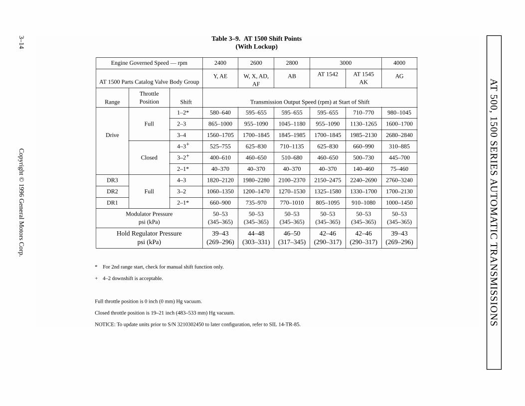
3–14C
opyright © 1996 G
eneral Motors C
orp.
AT
500, 1500 SE
RIE
S A
UT
OM
AT
IC T
RA
NS
MIS
SIO
NS
* For 2nd range start, check for manual shift function only.
+ 4–2 downshift is acceptable.
Full throttle position is 0 inch (0 mm) Hg vacuum.
Closed throttle position is 19–21 inch (483–533 mm) Hg vacuum.
NOTICE: To update units prior to S/N 3210302450 to later configuration, refer to SIL 14-TR-85.
Table 3–9. AT 1500 Shift Points(With Lockup)
Engine Governed Speed — rpm 2400 2600 2800 3000 4000
AT 1500 Parts Catalog Valve Body GroupY, AE W, X, AD,
AFAB AT 1542 AT 1545
AKAG
RangeThrottlePosition Shift Transmission Output Speed (rpm) at Start of Shift
1–2* 580–640 595–655 595–655 595–655 710–770 980–1045
Full 2–3 865–1000 955–1090 1045–1180 955–1090 1130–1265 1600–1700
Drive 3–4 1560–1705 1700–1845 1845–1985 1700–1845 1985–2130 2680–2840
4–3+ 525–755 625–830 710–1135 625–830 660–990 310–885
Closed 3–2+ 400–610 460–650 510–680 460–650 500–730 445–700
2–1* 40–370 40–370 40–370 40–370 140–460 75–460
DR3 4–3 1820–2120 1980–2280 2100–2370 2150–2475 2240–2690 2760–3240
DR2 Full 3–2 1060–1350 1200–1470 1270–1530 1325–1580 1330–1700 1700–2130
DR1 2–1* 660–900 735–970 770–1010 805–1095 910–1080 1000–1450
Modulator Pressurepsi (kPa)
50–53(345–365)
50–53(345–365)
50–53(345–365)
50–53(345–365)
50–53(345–365)
50–53(345–365)
Hold Regulator Pressurepsi (kPa)
39–43(269–296)
44–48(303–331)
46–50(317–345)
42–46(290–317)
42–46(290–317)
39–43(269–296)

PREVENTIVE MAINTENANCE
PREVENTIVE MAINTENANCE
3–14. TRANSMISSION STALL TEST AND NEUTRAL COOL-DOWN CHECK
a. Purpose
(1) Stall testing is performed to determinewhether a power complaint is due to an engine prob-lem or transmission malfunction.
(2) Stall speed is the maximum engine rpmattainable when the engine is at full throttle and whenthe torque converter turbine is not moving, or“stalled.”
(3) During a stall test, compare actual enginespeed at full throttle stall with established vehiclemanufacturer's specifications.
NOTE:Engine stall point data can be obtained from the ve-hicle manufacturer or from the equipment dealeror distributor.
(4) Stall tests are used as troubleshootingprocedures only — do not perform them as generalchecks or maintenance.
b. Stall Testing Preparation
(1) Make sure the fuel control linkage goesto full throttle and does not stick when released.
(2) Check the air induction system for re-strictions.
(3) Perform a cold check of the transmissionfluid level and adjust as necessary.
(4) Install an accurate tachometer (do notrely on the vehicle tachometer).
(5) Install a temperature gauge with theprobe in the transmission converter-out (to cooler)line.
(6) Block the vehicle wheels.
(7) Start the engine and let the transmissionsump warm to normal operating temperature 160–200°F(71–93°C).
(8) Perform a hot check of the transmissionfluid level and adjust as necessary.
(9) Turn all engine accessories OFF.
(10) Notify everyone to stay clear of the ve-hicle.
NOTE:• For vehicles with engines not equipped with
smoke controls, proceed to Paragraph c.• For vehicles with engines equipped with
smoke controls, skip Paragraph c and proceedto Paragraph d.
c. Stall Test Procedures — Vehicles WithoutSmoke-Controlled Engines
(1) Apply the vehicle parking and servicebrakes.
(2) Shift to D (Drive).
(3) Slowly accelerate to full throttle.
(4) When the tachometer levels off, recordthe maximum engine rpm attained.
(5) Slowly release the throttle.
(6) Shift to N (Neutral) or P (Park).
(7) Skip Paragraph d and proceed immedi-ately with Paragraph e — Cool-Down Check.
WARNING!While conducting a stall check, the vehicle mustbe positively prevented from moving. Apply theparking brake and service brake, and block thewheels securely. Warn personnel to keep clear ofthe vehicle and its travel path. Failure to do socan cause serious injury.
CAUTION:
Never maintain the stall condition for more than30 seconds at any one time because of the rapidrise in fluid temperature. Do not let the con-verter-out fluid temperature exceed 300°F(149°C). Do not rely on converter-out fluid tem-perature to limit stall duration. During stall con-ditions, internal temperatures rise much fasterthan converter-out fluid temperature. Allow thesystem to cool between stall checks by perform-ing the cool-down as described in Paragraph 3–14e. If the stall test is repeated, do not let the en-gine overheat.
Copyright © 1996 General Motors Corp. 3–15

AT 500, 1500 SERIES AUTOMATIC TRANSMISSIONS
d. Stall Test Procedures — Vehicles WithSmoke-Controlled Engines
NOTE:Because smoke controls and throttle-delay mecha-nisms inhibit engine acceleration, the stall testing mayneed to be performed while the vehicle is moving.
(1) Locate an isolated area to perform thedriving stall test.
(2) Select a hold range that will limit roadspeed (usually 2nd or 3rd range).
(3) Operate the engine at full throttle, maxi-mum governed rpm.
(4) Slowly depress the vehicle service brakeswhile staying at full throttle.
(5) When the vehicle comes to a stop, recordthe engine rpm — this is stall speed.
(6) Proceed immediately with Paragraph e— Cool-Down Check.
e. Neutral Cool-Down Check Procedure
(1) The neutral cool-down check determinesif the transmission fluid cools properly following anengine load condition. Perform this check immediatelyafter the engine speed has been recorded in the stalltest.
(2) Record the converter-out fluid temperature.
(3) With the transmission remaining in N (Neu-tral) or P (Park), run the engine at 1200–1500 rpm for twominutes to cool the fluid.
(4) At the end of two minutes, record the con-verter-out fluid temperature. Converter-out fluid tem-perature should return to within the normal operation.
f. Results
NOTE:Environmental conditions, such as ambient temper-ature, altitude, engine accessory loss variations,etc., affect the power input to the converter. Undersuch conditions, a stall speed deviation up to ±150rpm from specification can be accepted as withinnormal range.
(1) If the engine stall speed is more than 150rpm below the stall speed specified by the engine man-ufacturer, an engine problem is indicated, such as theneed for a tune-up.
(2) If the engine stall speed is more than 150rpm above specification, a transmission problem is in-dicated, such as slipping clutches, cavitation, or torqueconverter failure.
(3) An extremely low stall speed, such as 33percent of the specified engine stall rpm, during whichthe engine does not smoke, could indicate a free-wheeling torque converter stator.
(4) If the engine stall speed conforms tospecification, but the transmission fluid overheats, re-fer to the cool-down check. If the fluid does not coolduring the two-minute cool-down check, a stucktorque converter stator could be indicated.
(5) If the engine stall speed conforms tospecification and the cool-down check shows thattransmission fluid cools properly, refer to Table 3–12,Section C for troubleshooting procedures.
3–15. PRESERVATION AND STORAGE
a. Storage, New Transmissions (prior to instal-lation). New transmissions are tested at the Allisonfactory with preservative oil and drained prior to ship-ment. The residual oil remaining in the transmissionprovides adequate protection to safely store the trans-mission for up to one year (stored inside in conditionsof normal climate and with all shipping plugs in-stalled) without further treatment.
b. Preservation Methods. When the transmis-sion is to be stored or remain inactive for an extendedperiod (one or more years), specific preservation meth-ods are recommended to prevent damage due to rust,corrosion, and organic growth in the oil. Preservationmethods are presented for storage with and withouttransmission fluid.
c. Storage, One Year — WithoutTransmission Fluid
(1) Drain the transmission fluid.
(2) Spray two ounces (60 milliliters) ofVCI #10 through the fill tube.
3–16 Copyright © 1996 General Motors Corp.

PREVENTIVE MAINTENANCE
PREVENTIVE MAINTENANCE
(3) Seal all openings and the breather withmoisture-proof tape.
(4) Coat all exposed, unpainted surfaceswith preservative grease such as petrolatum (MIL-C-11796, Class 2).
(5) If additional storage time is required, re-peat Steps (2), (3), and (4) at yearly intervals.
d. Storage, One Year — With Transmission Fluid (Normally in a Vehicle Chassis)
(1) Drain the transmission fluid and replacethe filter element(s).
(2) Fill the transmission to operating levelwith a mixture of one part VCI #10 (or equivalent) to30 parts Allison-approved transmission fluid. Refer toParagraph 3–7. Add 1⁄4 teaspoon of Biobor® JF (orequivalent) for every 3 gallons (1 ml for every 10 li-ters) of fluid in the system.
NOTE:
When calculating the amount of Biobor® JF re-quired, use the total volume of the system, not justthe quantity required to fill the transmission. In-clude external lines, filters, and the cooler.
(3) Run the engine for approximately fiveminutes at 1500 rpm with the transmission in neutral.
(4) Drive the vehicle. Make sure the trans-mission shifts through all gears.
(5) Continue running the engine at 1500 rpmwith the transmission in neutral until normal operatingtemperature is reached.
(6) If normal operating temperature is lessthan 225°F (107°C), with the vehicle wheels blockedand the parking brake and service brake applied, shiftthe transmission to D (Drive) and stall the converter.When converter-out temperature reaches 225°F (107°C),stop the engine. Do not exceed 225°F (107°C).
(7) As soon as the transmission is coolenough to touch, seal all openings and the breatherwith moisture-proof tape.
(8) Coat all exposed, unpainted surfaces withpreservative grease such as petrolatum (MIL-C-11796,Class 2).
(9) If additional storage time is required, re-peat steps (2) through (8) at yearly intervals; except, itis not necessary to drain the transmission each year.Just add Motorstor and Biobor® JF (or equivalents).
e. Restoring Transmission to Service
(1) Remove all tape from openings and thebreather.
(2) Wash off all external grease with mineralspirits.
(3) If the transmission is new, drain the re-sidual preservative oil. Refill the transmission to theproper level as specified in Paragraphs 3–5 and 3–7.
(4) If the transmission was prepared for stor-age without transmission fluid, drain the residual oiland replace the filter element(s). Refill the transmis-sion to the proper level as specified in Paragraphs 3–5and 3–7.
WARNING!
Apply the parking brake, service brake, andblock the vehicle securely. Warn personnel tokeep clear of the vehicle and its travel path. Fail-ure to do so can cause serious injury.
CAUTION:
Never maintain the stall condition for more than30 seconds at any one time because of the rapidrise in fluid temperature. Do not let the con-verter-out fluid temperature exceed 300°F(149°C). Do not rely on converter-out fluid tem-perature to limit stall duration. During stall con-ditions, internal temperatures rise much fasterthan converter-out fluid temperature. Allow thesystem to cool between stall checks by perform-ing the cool-down as described in Paragraph 3–14e. If the stall test is repeated, do not let the en-gine overheat.
Copyright © 1996 General Motors Corp. 3–17
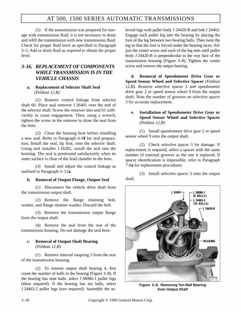
AT 500, 1500 SERIES AUTOMATIC TRANSMISSIONS
(5) If the transmission was prepared for stor-age with transmission fluid, it is not necessary to drainand refill the transmission with new transmission fluid.Check for proper fluid level as specified in Paragraph3–5. Add or drain fluid as required to obtain the properlevel.
3–16. REPLACEMENT OF COMPONENTS WHILE TRANSMISSION IS IN THE VEHICLE CHASSIS
a. Replacement of Selector Shaft Seal(Foldout 12,B)
(1) Remove control linkage from selectorshaft 60. Place seal remover J 26401 over the end ofthe selector shaft. Screw the remover into seal 61 suffi-ciently to cause engagement. Then, using a wrench,tighten the screw in the remover to draw the seal fromthe bore.
(2) Clean the housing bore before installinga new seal. Refer to Paragraph 4–6f for seal prepara-tion. Install the seal, lip first, onto the selector shaft.Using seal installer J 26282, install the seal into thehousing. The seal is positioned satisfactorily when itsouter surface is clear of the lead chamfer in the bore.
(3) Install and adjust the control linkage asoutlined in Paragraph 3–12a.
b. Removal of Output Flange, Output Seal
(1) Disconnect the vehicle drive shaft fromthe transmission output shaft.
(2) Remove the flange retaining bolt,washer, and flange retainer washer. Discard the bolt.
(3) Remove the transmission output flangefrom the output shaft.
(4) Remove the seal from the rear of thetransmission housing. Do not damage the seal bore.
c. Removal of Output Shaft Bearing(Foldout 12,B)
(1) Remove internal snapring 5 from the rearof the transmission housing.
(2) To remove output shaft bearing 4, firstcount the number of balls in the bearing (Figure 3–8). Ifthe bearing has nine balls, select J 38086-1 puller legs(three required). If the bearing has ten balls, selectJ 24463-2 puller legs (two required). Assemble the se-
lected legs with puller body J 24420-B and bolt J 24463.Engage each puller leg into the bearing by placing thefoot of the leg between two bearing balls. Then twist theleg so that the foot is forced under the bearing races. Ad-just the center screw and each of the leg nuts until pullerbody J 24420-B is perpendicular to the rear face of thetransmission housing (Figure 3–8). Tighten the centerscrew and remove the output bearing.
d. Removal of Speedometer Drive Gear orSpeed Sensor Wheel and Selective Spacer (Foldout12,B). Remove selective spacer 3 and speedometerdrive gear 2 or speed sensor wheel 9 from the outputshaft. Note the number of grooves on selective spacer3 for accurate replacement.
e. Installation of Speedometer Drive Gear orSpeed Sensor Wheel and Selective Spacer(Foldout 12,B)
(1) Install speedometer drive gear 2 or speedsensor wheel 9 onto the output shaft.
(2) Check selective spacer 3 for damage. Ifreplacement is required, select a spacer with the samenumber of external grooves as the one it replaced. Ifspacer identification is impossible, refer to Paragraph7-6a for replacement procedures.
(3) Install selective spacer 3 onto the outputshaft.
Figure 3–8. Removing Ten-Ball Bearingfrom Output Shaft
H02885
BEARING
J 24420-B
J 24463 J 38086-1(9 BALLS)J 24463-2(10 BALLS)
3–18 Copyright © 1996 General Motors Corp.

PREVENTIVE MAINTENANCE
PREVENTIVE MAINTENANCE
f. Installation of Output Shaft Bearingand Snapring
(1) Clean the bearing bore. Make suresnapring 9 (Foldout 12,A) is seated in its groove and isnot damaged.
(2) Using tool J 24446, install bearing 4(Foldout 12,B) into the transmission housing. The toolwill seat the bearing squarely against snapring 9 (Fold-out 12,A).
(3) Install snapring 5 (Foldout 12,B), bev-eled side outward, into its groove in the transmissionhousing. Be sure the snapring is fully expanded.
g. Installation of Output Seal (Foldout 12,B)
(1) Refer to Paragraph 4-6f for preparationof seal 6.
(2) Start the seal, lip first, squarely into therear bore of the transmission housing.
(3) Using installer tool J 23631, drive theseal into the housing until the installer seats against thehousing.
h. Installation of Output Flange
(1) Lubricate the splines of the shaft and out-put flange and install the output flange onto the outputshaft.
(2) Install the flange retainer washer into theflange. Retain the flange to the output shaft with one1⁄2-20 x 11⁄2 inch Type BH patch bolt (P/N 29510838)and one 17⁄32 inch hardened plain washer (P/N 9411417)(Figure 3–9). Do not use the earlier style bolt. Tightenthe bolt to 102–121 lb ft (138–164 N·m).
(3) Connect the vehicle drive shaft to thetransmission output flange. (See vehicle installationmanual for alignment procedure, if required).
3–17. TROUBLESHOOTING — BEFORE REMOVAL OR OPERATION OF TRANSMISSION
a. Visual Inspection. Do not operate the vehicleprior to completing the procedures described in thisParagraph. Inspect for transmission fluid leakage. Vi-sually inspect all splitlines, connections, valve bodies,fluid level indicator tube, and plugs and hoses at thetransmission and cooler. Fluid leakage at splitlinesmay be caused by loose mounting bolts or defectivegaskets. Tighten all bolts, plugs, and connectionswhere leakage is found. If mounting bolts are tight andfluid continues to leak, install a new gasket. Fluid leak-ing from the fluid level indicator tube may be causedfrom foaming and aerating (Paragraph 3–3b). Checklinkage (Paragraph 3–12).
b. Vacuum Modulator Check
(1) Vacuum diaphragm leak check. Inserta pipe cleaner into the vacuum modulator connectorpipe as far as possible and check for the presence oftransmission fluid. If fluid is found, replace the modu-lator.
NOTE:
Gasoline or water vapor may settle in the vacuumside of the modulator. If this is found without thepresence of transmission fluid, the modulator neednot be changed.
(2) Atmospheric leak check. Apply a lib-eral coating of soap bubble solution to the vacuumconnector pipe seam, crimped upper-to-lower housingseam, and threaded screw seal. Using a short piece ofrubber tubing, apply air pressure to the vacuum pipeby blowing into the tube and observe for leak bubbles.If bubbles appear, replace the modulator.
NOTE:
Do not use any method which will produce morethan 6 psi (41 kPa) air pressure, as pressure over 6psi (41 kPa) may damage the modulator.
CAUTION:
Do not use a hammer or mallet to drive the flangeonto the output shaft. Hammering the flangeonto the shaft could damage the internal, cagedroller bearings and output bearing.
Copyright © 1996 General Motors Corp. 3–19

AT 500, 1500 SERIES AUTOMATIC TRANSMISSIONS
(3) Modulator comparison check. Using acomparison gauge (Figure 3–10), compare the load of aknown good modulator with the assembly in question.
• Install a modulator that is known to beacceptable on either end of the gauge.
• Install the modulator in question on theopposite end of the gauge.
• Holding the modulators in a horizontal posi-tion, bring them together under pressure until either modulator sleeve end just touches the line in the center of the gauge. The gap be-tween the opposite modulator sleeve end and the gauge line must be 0.062 inch (1.57 mm) or less. If the distance is greater than this amount, replace the modulator in question.
Figure 3–9. Identification of Flange Retaining Bolt
Source and material gradeidentification markings toappear on top of head inthis area
CONSTANT ANNULAR GROOVE
Six (6) radial slots spacedsixty (60) degrees apart
3⁄4 in.
1 ⁄2 in.
V01301
13⁄16 in.
1⁄2 in.
Source and material gradeidentification markings toappear on top of head inthis area
VARYING ANNULAR GROOVEFive (5) radial slots spacedsixty (60) degrees apart
EARLIER BOLTP/N 23014159STANDARD (TYPE AA PATCH) SAE GRADE 83⁄4 in. HEXAGON HEADSIX (6) GRADE ID MARKINGS*CONSTANT UNDERHEAD FILLET**
LATER BOLTP/N 29510838NON-STANDARD (TYPE BH PATCH) SAE GRADE 8OFFSET, 13⁄16 in. HEXAGON HEADFIVE (5) GRADE ID MARKINGS***VARYING UNDERHEAD FILLET**
* Radial slots spaced approximately sixty (60) degrees apart.** Annular groove at the junction of the head bearing surface and the bolt shank.
*** Radial slots spaced approximately sixty (60) degrees apart; may be random relative to hexagon butshall be oriented such that three (3) wide slots are symmetrically over span of large recess diameter.
3–20 Copyright © 1996 General Motors Corp.

PREVENTIVE MAINTENANCE
PREVENTIVE MAINTENANCE
Figure 3–10. Gauge for Comparing Vacuum Modulators
(4) Sleeve alignment check. Roll the mainbody of the modulator on a flat surface and observe thesleeve for concentricity to the can. If the sleeve is con-centric and the plunger is free, the modulator is ac-ceptable.
(5) A modulator passing all checks in Steps(1) through (4) should be an acceptable part.
3–18. TROUBLESHOOTING — BEFORE REMOVAL AND DURING OPERATION
a. Determine Cause of Trouble
(1) If the inspections in Paragraph 3–17 donot reveal the cause of the problem and the vehicle isoperable, further troubleshooting is necessary. Do notremove the transmission from the vehicle until thecause of the trouble listed in the troubleshooting chartis checked.
(2) The engine and transmission must be re-garded as a single package during troubleshooting. Athorough study of the description and operation of thecomponents and hydraulic system will be helpful indetermining the cause.
b. Proper Engine Tuning. In order to make athorough test of the transmission while it is mountedin the vehicle, be sure that the engine is properly tunedand the fluid level in the transmission is correct. Referto Paragraph 3–5 for checking fluid level.
c. Hydraulic Pressure Checking Procedures
(1) Table 3–10 is for checking main pressureon transmissions having demodulated main pressure.
(2) Table 3–11 is for checking main pressureon transmissions having modulated main pressure.
(3) Table 3–12 is for checking retarderpressure.
(4) The pressure check points are shown inFigures 3–11, 3–12, and 3–13.
3–19. TROUBLESHOOTING — TRANSMISSION REMOVED FROM VEHICLE
When the malfunction of a transmission is not ascer-tained by tests or inspections before removal fromthe vehicle, the transmission may be mounted in atest stand and checked (if a test stand is available).Particular attention must be given to proper fluidlevel and to proper linkage adjustment in every trans-mission test.
3–20. TROUBLESHOOTING PROCEDURES
Table 3–13, Troubleshooting Chart, lists possiblecauses of transmission troubles and their remedies.Capital letters indicate the symptom; numerals follow-ing the symptom indicate several possible causes; cor-responding numerals in the right column indicate rem-edies for the causes.
ENDS TO BE SQUAREWITHIN 1⁄64 in.
(0.40 mm)
SCRIBEDLINE
V02886
1⁄2 in.(12.7 mm)
3⁄8 in. (131.03 mm) TO13⁄32 in. (9.53 mm)ROUND OR FLAT STOCK
1 in.(25.4 mm)
WARNING!
Observe safety precautions during hydraulicpressure check procedures. All personnel muststand clear of the vehicle. Take precautionsagainst movement of the vehicle. Be sure thatgauges (vacuum, pressure, tachometer) have ex-tended lines so that they can be read from insidethe vehicle.
Copyright © 1996 General Motors Corp. 3–21

AT 500, 1500 SERIES AUTOMATIC TRANSMISSIONS
Figure 3–11. Transmission Check Points
Figure 3–12. Transmission Check Points (Models Without Retarder)
H02887
MODULATOR ACCESS(MECHANICAL OR VACUUM)
MAIN PRESSURE
H02888
REVERSE SIGNALPRESSURE
LOCKUP PRESSURE(AT 1500 SERIES)
OIL FILL TUBE
DRAIN PLUG
TO COOLER
FROM COOLER(AUXILIARY FILTER)
BREATHER
3–22 Copyright © 1996 General Motors Corp.

PREVENTIVE MAINTENANCE
PREVENTIVE MAINTENANCE
Figure 3–13. Transmission Check Points (Models With Retarder)
Table 3–10. Main Pressure Check Procedure (Models With Demodulated Main Pressure)
WARNING!
Observe safety precautions during hydraulic pressure check procedures. All personnel must stand clearof the vehicle. Take precautions against movement of the vehicle. Be sure that gauges (vacuum, pressure,tachometer) have extended lines so that they can be read from inside the vehicle.
PROCEDURES:
(1) All transmission fluid level and pressure checks must be made at normal operating temperatures(160–200°F (71–93°C) sump; 180–220˚F (82–104˚C) converter-out). Check transmission fluidlevel.
(2) Connect 0–300 psi (0–2068 kPa) oil pressure gauge. Connect tachometer.
(3) Check Neutral and Forward pressures with engine running at 1200 rpm, brakes applied.
(4) Check Reverse pressure, with engine running at 2500 rpm, brakes applied. Reconnect driveline.
(5) Check Lockup pressures with transmission in third and fourth range, with engine at full throttle.
NEUTRAL 135-155 psi(931–1068 kPa)
FORWARD 135–155 psi(931–1068 kPa)
REVERSE 230–275 psi(1586–1896 kPa)
LOCKUP 120 psi min(827 kPa min)
ECAPSORE AE LI B O MOTUA DETI NU ACI RE MA
FOSR
EKRO
WTN
EMEL
PMILARUTLUCIRGADNA
UAWUAW933933
DIVISION OFDIVISION OFGENERAL MOTORSGENERAL MOTORS
CORPORATIONCORPORATIONINDIANAPOLISINDIANAPOLIS
INDIANAINDIANA
SERIAL NO.
XXXXX
XX XXXXX
XXXXXXX
MODELNO.
PART NO.
RETARDER VALVE BODYFIRST CLUTCH PRESSURE TAP
(NEAR SPEEDOMETER PROVISION)
TRANSMISSION “FROM COOLER” PORT
FROM PRIMARY COOLERTRANSMISSION “TO COOLER” PORT
WIRING HARNESS CONNECTOR
TO PRIMARY COOLER
TO SECONDARY COOLER
CONNECTS TO TRANSMISSION “MAIN” PRESSURE TAP(OPPOSITE SIDE OF TRANSMISSION)
CONNECTS TO TRANSMISSION “TO COOLER” PORT
TEMPERATURE SENDING UNIT
V02889
Copyright © 1996 General Motors Corp. 3–23

AT 500, 1500 SERIES AUTOMATIC TRANSMISSIONS
Table 3–11. Main Pressure Check Procedure (Models With Modulated Main Pressure)
Table 3–12. Retarder Pressure Check Procedure
WARNING!
Observe safety precautions during hydraulic pressure check procedures. All personnel must stand clearof the vehicle. Take precautions against movement of the vehicle. Be sure that gauges (vacuum, pressure,tachometer) have extended lines so that they can be read from inside the vehicle.
NOTE: Perform procedures (1), (2), (3), (4), and (5) from Table 3–10.
VACUUM MODULATOR MECHANICAL MODULATOR
Install a tee in the modulator line and connect avacuum gauge to measure pressure.
Disconnect the modulator cable from the throttle linkage.
NEUTRAL Make sure there are 15 inches or more vacuum. Main pressure should be 90–110 psi(621–758 kPa).
Push or pull the cable to the idle position against theinternal stop. Main pressure should be 90–110 psi(621–758 kPa).
If main pressure is 135–155 psi (931–1068 kPa), the transmission has demodulated main pressure.Use Table 3–10.
Push or pull the actuator cable to full throttle position against internal stop.
NEUTRAL 135–155 psi (931–1068 kPa) 135–155 psi (931–1068 kPa)
FORWARD 135–155 psi (931–1068 kPa)Uncouple the output flange.
135–155 psi (931–1068 kPa)Uncouple the output flange.
REVERSE 230–275 psi (1586–1896 kPa) 230–275 psi (1586–1896 kPa)Properly adjust mechanical linkage.
PROCEDURES:
(1) Remove the temperature probe and install 0–100 psi (0–689 kPa) oil pressure gauge.
(2) Drive the vehicle until the transmission reaches fourth range.
(3) Apply the retarder, 100 percent.
(4) 100 percent apply pressure should be 50–62 psi (345–427 kPa).
(5) Release the retarder and re-apply the retarder at 50 percent.
(6) 50 percent apply pressure should be 20–32 psi (138–220 kPa).
NOTE: Retarder pressure will drop during downshift.
3–24 Copyright © 1996 General Motors Corp.

PREVENTIVE MAINTENANCE
PREVENTIVE MAINTENANCE
Table 3–13. Troubleshooting Chart
Problem Probable Causes Suggested Remedies
A. Abnormal Automatic Shifts
Shifts occurring at too high speed Governor valve malfunctioning (stuck).
Clean or replace governor screen and/or governor. The governor may be disassembled for cleaning and inspection only if the kit consisting of two governor weight pins and cover gasket is available. Refer to Paragraphs 5–3e, 5–3h(5), 6–5, 7–10a, and 7–11a.
Vacuum modulator vacuum hose to engine kinked or leaking — light throttle shifting delayed.
Replace hose. Be sure vacuum line is free from kinks or bends and not close to exhaust components.
Vacuum modulation delayed. Replace vacuum modulator. Be sure that O-ring is installed and that the modulator vacuum fitting is facing forward and positioned 10° below horizontal. Refer to Paragraphs 5–3c and 7–11b.
Mechanical actuator cable kinked, broken, or not properly adjusted.
Replace, adjust, or repair cable. Full actuator control cable travel must correspond with full throttle (push or pull system). Refer to the latest edi-tion of SA1321, AT Mechanic’s Tips.
Mechanical actuator malfunctioning. Replace actuator.
Shift signal valve adjustment too high.
Adjust shift points. Refer to Para-graph 3–13.
Valves sticking. Replace or rebuild main control valve assembly. Refer to Paragraph 6–6.
Improper modulation. Inspect and replace, if necessary, modulator valve and modulator body. Refer to Paragraphs 6–6a(5) and 6–6b(16).
Copyright © 1996 General Motors Corp. 3–25

AT 500, 1500 SERIES AUTOMATIC TRANSMISSIONS
A. Abnormal Automatic Shifts (cont’d)
Shifts occurring at too low speed — full throttle
Governor spring weak or missing. Replace governor. Refer to Para-graphs 5–3e and 7–10a.
Mechanical actuator kinked, bro-ken, or not properly adjusted.
Replace, adjust, or repair cable. Full actuator control cable travel must correspond with full throttle (push or pull system). Refer to the latest edi-tion SA1321, AT Mechanic's Tips.
Shift signal valve spring adjustment too loose.
Tighten spring adjusting ring to specification. Refer to Paragraph3–13.
Modulator valve stuck open. Check spring adjustment. Clean or replace modulator valve. Refer to Paragraphs 6–6a(5) and 6–6b(16).
Rough shifting Governor valve malfunctioning. Clean or replace governor screen and/or governor. The governor may be disassembled for cleaning and inspection only if the kit consisting of two governor weight pins and cover gasket is available. Refer to Paragraphs 5–3e, 5–3h(5), 6–5,7–10a, and 7–11a.
Vacuum modulator valve spring not properly adjusted — vacuum hose kinked or leaking.
Check spring adjustment. Replace hose. Refer to Paragraph 3–13.
Mechanical actuator cable kinked, broken, or not properly adjusted.
Replace, adjust, or repair cable. Full actuator control cable travel must correspond with full throttle (push or pull system). Refer to the latest edi-tion of SA1321, AT Mechanic’s Tips.
Mechanical actuator malfunctioning. Replace actuator.
Vacuum modulator failed. Replace vacuum modulator. Be sure that O-ring is installed and that the modulator vacuum fitting is facing forward and positioned 10° below horizontal. Refer to Paragraphs 5–3c and 7–11b.
Table 3–13. Troubleshooting Chart (cont’d)
Problem Probable Causes Suggested Remedies
3–26 Copyright © 1996 General Motors Corp.

PREVENTIVE MAINTENANCE
PREVENTIVE MAINTENANCE
A. Abnormal Automatic Shifts (cont’d)
Rough shifting (cont’d) Trimmer valves sticking (broken spring).
Replace or rebuild main control valve body assembly. Refer to Para-graph 6–6.
Control valves sticking. Replace or rebuild main control valve body assembly. Refer to Para-graph 6–6.
Modulator valve sticking. Clean modulator valve. Check vac-uum modulator. Adjust spring. Refer to Paragraphs 6-6a and 6-6b.
Engine idle speed too fast (N to D). Adjust engine idle screw. Refer to vehicle service manual.
Shift selector linkage out of adjust-ment.
Adjust linkage. Refer to the latest edition of SA1321, AT Mechanic’s Tips.
No specific shift; i.e., 1–2, 2–3, 3–4 (up or down)
Governor valve malfunctioning. Clean or replace governor screen and/or governor. The governor may be disassembled for cleaning and inspection only if the kit consisting of two governor weight pins and cover gasket is available. Refer to Paragraphs 5–3e, 5–3h(5), 6–5, 7–10a, and 7–11a.
Specific range valves malfunction-ing (sticking).
Replace or rebuild main valve body assembly. Refer to Paragraph 6–6.
Shift flare during range shifts, AT 545 models only.
Incorrect trimmer valves installed. Replace trimmer valves. Refer to Paragraph 6–6a(9).
B. Abnormal Activities or Responses
Excessive creep in first range and reverse
Engine idle speed set too high. Adjust to correct idle speed. Refer to vehicle service manual.
Shift selector linkage unhooked. Hook up shift selector linkage — quadrant gates must agree with transmission model. Detent posi-tions at transmission must conform with gates on quadrant. Refer to vehicle service manual and to the latest edition of SA1321, AT Mechanic’s Tips.
Table 3–13. Troubleshooting Chart (cont’d)
Problem Probable Causes Suggested Remedies
Copyright © 1996 General Motors Corp. 3–27

AT 500, 1500 SERIES AUTOMATIC TRANSMISSIONS
B. Abnormal Activities or Responses (cont’d)
Vehicle moves backward in neutral Shift selector linkage out of adjust-ment.
Repair or replace linkage.*
Fourth clutch failed and dragging. Rebuild fourth clutch. Refer to Para-graphs 5–3l and 7–6b.
Shift selector linkage defective or broken.
Repair or replace linkage.*
Main pressure low. Refer to Chart E, Low Pressure.
Shift selector not engaged at control valve.
Install or replace parts involved (inside oil pan). Refer to Paragraphs 5–3h and 7–10a.
Low fluid level. Fill to proper fluid level. Refer to Paragraphs 3–4 through 3–10.
Vehicle moves forward in neutral Incorrect idle speed. Adjust to correct idle speed.
Shift selector linkage out of adjust-ment.
Repair or replace linkage.*
Forward clutch failed and dragging. Rebuild forward clutch. Refer to Paragraph 6–8.
Reverse warning buzzers and/or vehicle backup lights come on dur-ing forward operation.
Improper 1–2 relay valve installed. Install new 1–2 relay valve. Refer to Paragraph 6–6a(11).
C. Abnormal Stall Check Speed
High stall speeds Low fluid level. Add fluid to proper level. Refer to Paragraphs 3–4 through 3–10.
Clutch pressure low. Refer to Chart E, Low Pressure.
Forward clutch slippage.** Rebuild forward clutch. Refer to Paragraph 6–8.
First clutch slippage.** Rebuild first clutch. Refer to Para-graphs 5–3q and 7–4a, b.
* Shift selector linkage must be free and secure. Hook up shift selector linkage — quadrant gates must agree with transmission model. Detent positions at transmission must conform with gates on quadrant. Refer to vehicle service manual and to Paragraph 3–12a.
** Clutch slippage may be recognized by alternate racing and loading of the engine, which is at times, accompanied by a violent chatter. Refer to slippage charts.
Table 3–13. Troubleshooting Chart (cont’d)
Problem Probable Causes Suggested Remedies
3–28 Copyright © 1996 General Motors Corp.

PREVENTIVE MAINTENANCE
PREVENTIVE MAINTENANCE
A. Abnormal Stall Check Speed (cont’d)
High stall speeds (cont’d) Fourth clutch (reverse) slipping. Rebuild fourth clutch. Refer to Para-graph 6–11.
Low stall speeds Engine not performing efficiently (may be due to plugged or restricted injectors or high altitude conditions).
Refer to engine manufacturer’s man-ual or vehicle service manual.
Broken converter parts. Replace or rebuild converter assem-bly.*** Refer to Paragraph 6–4.
Stall speeds of 50 percent of normal (implies freewheeling stator).
Replace or rebuild converter assem-bly.*** Refer to Paragraph 6–4.
B. Leaking Fluid
Fluid leaking into converter housing Engine crankshaft rear oil seal leak-age.
Refer to vehicle service manual.
Metal-encased lip type seal at front of input charging pump leaking.
Replace pump seal. Refer to Para-graphs 6–7a(6) and 6–6d(10) or (12).
Seal around OD of oil pump leaking. Replace OD pump seal. Refer to Paragraphs 6–7a(5) and 6–6d(13).
Cracked weld in torque converter assembly leaking.
Replace or repair converter assem-bly.*** Refer to Paragraph 6–4.
Torque converter pump hub worn at seal area.
Replace torque converter pump hub.*** Refer to Paragraph 6–4.
Fluid leak at output shaft Faulty or missing seal at output flange.
Install new seal in rear of transmis-sion housing. Refer to Paragraphs3–16b and g.
Flange worn at seal surface. Replace flange. Refer to Paragraphs 3–16b and h.
*** Note: Except for AT 543 models, no repairs can be made because the torque converter assembly is closed and welded after assembly of theinternal parts.
Table 3–13. Troubleshooting Chart (cont’d)
Problem Probable Causes Suggested Remedies
Copyright © 1996 General Motors Corp. 3–29

AT 500, 1500 SERIES AUTOMATIC TRANSMISSIONS
C. Low Pressure
Low main pressure in all ranges Low fluid level. Add fluid to the proper level. Refer to Paragraphs 3–4 through 3–10.
Filter element(s) clogged. Replace filter or element(s). Refer to Paragraph 3–10.
Sealring on intake tube leaking or missing.
Install new sealring onto the top end of the intake tube. Refer to Para-graph 7–10b.
Main-pressure regulator valve spring weak.
Replace spring. Refer to Paragraphs 6–7a and 6–7d.
Main control valve body leakage. Replace or rebuild main control valve body assembly. Refer to Para-graph 6–6.
Valves sticking (trimmer relays, and main pressure regulator).
Replace or rebuild main control valve body assembly. Refer to Para-graph 6–6.
Input charging pump worn or dam-aged.
Replace or rebuild pump. Refer to Paragraphs 5–3i, 6–7, and 7–8b.
Missing priority valve. Replace missing valve. Refer to Paragraphs 6–6a and 6–6b.
Low main pressure in first range, normal pressure in other forward ranges
First range circuit leakage in control valve body.
Replace or rebuild main control valve body assembly. Refer to Para-graph 6–6.
Excessive leakage at first clutch pis-ton seals.
Overhaul transmission. Replace pis-ton seals.
Low lubrication pressure Low fluid level. Add fluid to the proper level. Refer to Paragraphs 3–4 through 3–10.
Engine idle speed too low. Refer to vehicle service manual.
Cooler lines restricted or leaking. Check for kinks or leakage. Reroute or replace lines as necessary.
Excessive internal fluid leakage. Check other pressures in this chart. Also check valve body mounting bolts. Refer to Paragraph 7–10a.
Table 3–13. Troubleshooting Chart (cont’d)
Problem Probable Causes Suggested Remedies
3–30 Copyright © 1996 General Motors Corp.

PREVENTIVE MAINTENANCE
PREVENTIVE MAINTENANCE
D. Slippage†/**
Excessive slippage and clutch chat-ter in only one range
Clutch slipping in that range. Rebuild the specific clutch that is slipping and replace piston seals.
Excessive fluid leakage in rangepiston seals.
Overhaul clutch and piston assem-bly.
Fluid leakage in valve components for that particular range.
Replace or rebuild main control valve body assembly. Refer to Para-graph 6–6.
Trimmer valve stuck open. Replace or rebuild main control valve body assembly. Check trimmer valve for freedom of movement. Refer to Paragraph 6–6.
Cycling priority valve. Replace or rebuild main control valve body assembly. Inspect prior-ity valve. Refer to Paragraph 6–6.
Slippage in all forward ranges Low fluid level. Add fluid to proper level. Refer to Paragraphs 3–4 through 3–10.
Clutch main pressure low. Refer to Chart E, Low Pressure
Forward clutch slipping. Rebuild forward clutch and replace piston seals. Refer to Paragraph 6–8.
Sealrings on front support hub bro-ken.
Replace sealrings. Refer to Para-graphs 5–3i and 7–8b.
Slippage in fourth range and reverse only
Fourth clutch slipping. Rebuild clutch and replace piston seals. Refer to Paragraph 6–11.
Trimmer valve sticking. Replace or rebuild main control valve body assembly. Inspect trim-mer valve. Refer to Paragraph 6–6.
Broken sealrings on center support assembly hub.
Replace sealrings. Refer to Para-graphs 6–12a and 6–12c.
Clutch piston sealrings cut. Replace sealrings. Refer to Para-graphs 6–11a and 6–11c.
Check balls not seating in rotating clutch housings.
Inspect check balls for contamina-tion and proper operation. Refer to Paragraph 4–5p.
† If unit is modified for split shaft PTO, all external circuitry must be removed before troubleshooting.
** Clutch slippage may be recognized by alternate racing and loading of the engine, which is at times, accompanied by a violent chatter.
Table 3–13. Troubleshooting Chart (cont’d)
Problem Probable Causes Suggested Remedies
Copyright © 1996 General Motors Corp. 3–31
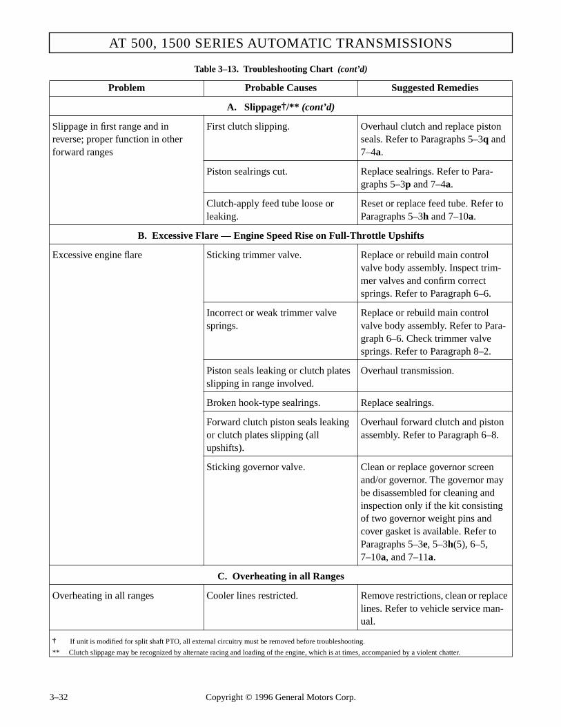
AT 500, 1500 SERIES AUTOMATIC TRANSMISSIONS
A. Slippage†/** (cont’d)
Slippage in first range and in reverse; proper function in otherforward ranges
First clutch slipping. Overhaul clutch and replace piston seals. Refer to Paragraphs 5–3q and 7–4a.
Piston sealrings cut. Replace sealrings. Refer to Para-graphs 5–3p and 7–4a.
Clutch-apply feed tube loose or leaking.
Reset or replace feed tube. Refer to Paragraphs 5–3h and 7–10a.
B. Excessive Flare — Engine Speed Rise on Full-Throttle Upshifts
Excessive engine flare Sticking trimmer valve. Replace or rebuild main control valve body assembly. Inspect trim-mer valves and confirm correct springs. Refer to Paragraph 6–6.
Incorrect or weak trimmer valve springs.
Replace or rebuild main control valve body assembly. Refer to Para-graph 6–6. Check trimmer valve springs. Refer to Paragraph 8–2.
Piston seals leaking or clutch plates slipping in range involved.
Overhaul transmission.
Broken hook-type sealrings. Replace sealrings.
Forward clutch piston seals leaking or clutch plates slipping (all upshifts).
Overhaul forward clutch and piston assembly. Refer to Paragraph 6–8.
Sticking governor valve. Clean or replace governor screen and/or governor. The governor may be disassembled for cleaning and inspection only if the kit consisting of two governor weight pins and cover gasket is available. Refer to Paragraphs 5–3e, 5–3h(5), 6–5,7–10a, and 7–11a.
C. Overheating in all Ranges
Overheating in all ranges Cooler lines restricted. Remove restrictions, clean or replace lines. Refer to vehicle service man-ual.
† If unit is modified for split shaft PTO, all external circuitry must be removed before troubleshooting.
** Clutch slippage may be recognized by alternate racing and loading of the engine, which is at times, accompanied by a violent chatter.
Table 3–13. Troubleshooting Chart (cont’d)
Problem Probable Causes Suggested Remedies
3–32 Copyright © 1996 General Motors Corp.

PREVENTIVE MAINTENANCE
PREVENTIVE MAINTENANCE
A. Overheating in all Ranges (cont’d)
Overheating in all ranges (cont’d) Broken parts in torque converter.†† Replace or repair torque converter assembly. Refer to Paragraph6–4.***
Aerated fluid. Adjust fluid to proper level. Check for defective sealring at intake tube. Check for defective input charging pump. Refer to Paragraphs 3–4 through 3–10, 5–3g, 5–3i, 6–7, 7–8b, and 7–10b.
Cooler flow loss due to internalleakage.
Overhaul transmission.
J. Transmission Throws Transmission Fluid Out of Fill Tube and/or Breather
Transmission throws fluid out of fill tube and/or breather
Dipstick loose. Tighten cap. Replace if necessary.
Fluid level too high. Drain to proper fluid level. Refer to Paragraphs 3–4 through 3–10.
Fluid level too low. Fill to proper fluid level. Refer to Paragraphs 3–4 through 3–10.
Vacuum modulator failed. Replace vacuum modulator.
Fill tube not vented or is plugged. Check for blockage and clean if nec-essary.
Breather stopped up (clogged). Clean or replace breather. Refer to Paragraph 3–11.
Water in transmission fluid. Drain and replace fluid. Refer to Paragraphs 3–4 through 3–10.
Dipstick gasket worn. Replace gasket or dipstick.
Improper dipstick marking (improper fluid level).
Replace dipstick. Refer to Paragraph 3–4.
†† Can also result in excessive fuel consumption.
*** Note: Except for AT 543 models, no repairs can be made because the torque converter assembly is closed and welded after assembly of theinternal parts.
Table 3–13. Troubleshooting Chart (cont’d)
Problem Probable Causes Suggested Remedies
Copyright © 1996 General Motors Corp. 3–33

AT 500, 1500 SERIES AUTOMATIC TRANSMISSIONS
K. Dirty Transmission Fluid
Dirty fluid Failure to change fluid at proper interval.
Change fluid and install new filter or element(s). Refer to Paragraph 3–10.
Excessive heat. Refer to Chart H, Overheating.
Clutch failure. Overhaul transmission.
Damaged filter or element(s). Replace filter or element(s). Refer to Paragraph 3–10.
Engine rear oil seal failed. Replace engine rear oil seal. Refer to engine repair manual.
L. Noise Occurring Intermittently (Buzzing)
Noise occurring intermittently (buzzing)
Low fluid level. Add fluid to proper level. Refer to Paragraphs 3–4 through 3–10.
Air leak at intake tube (O-ringdamaged).
Replace intake tube seal and filter. Refer to Paragraphs 5–3g, and7–10b.
Clogged filter or element(s). Replace filter or element(s). Refer to Paragraph 3–10.
Aerated fluid. Improper fluid level. Refer to Para-graphs 3–4 through 3–10.
Damaged filter or element(s). Replace filter or element(s). Refer to Paragraph 3–10.
M. Vehicle Will Not Push Start
Vehicle will not push start Normal operation (no push-start pump).
Do not attempt to push start.
N. Accelerated Clutch Wear, AT 545 Only
Accelerated clutch wear in clutches that experience extended trim times
Incorrect trimmer valves installed. Replace trimmer valves. Refer to Paragraph 6–6a(9).
Table 3–13. Troubleshooting Chart (cont’d)
Problem Probable Causes Suggested Remedies
3–34 Copyright © 1996 General Motors Corp.

Section 4 – GENERAL OVERHAUL INFORMATION
4–1. SCOPE
This section provides general information for over-haul, cleaning, inspection, and general assembly pro-cedures for the transmission. It provides illustrationsand explanations for the fabrication of improvisedtooling. A listing and illustration of special tools is in-cluded for your convenience.
4–2. TOOLS AND EQUIPMENT
a. Improvised Tools and Equipment. The fol-lowing items may be improvised.
• Work table — 1500 pound (700 kg)capacity (Figure 4–1)
• Gauge for comparing vacuum modulator (Figure 3–9).
Copyright © 1996 Ge
NOTE:
The transmission holding fixture (Figure 5–1) maybe mounted on the work table.
b. Special Tools. Special tools are illustrated inFigures 4–2 through 4–4. They are identified in the ta-ble following the illustrations. These special tools areavailable from:
Kent-Moore Tool Division*29784 Little MackRoseville, Michigan 48066
Aidco, Inc.*800 Liberty StreetAdrian, Michigan 49221
Figure 4–1. Typical Work Table
48 in.(120 cm)
78 in.(200 cm)
24 in.(60 cm)
4 x 4 in. LEGS(10 x 10 cm)
2 x 6 in. BOARD(5 x 15 cm)FOR TOP FRAMEAND LEG BRACKETS
TRANSMISSION FLUID DRAIN
STEEL TOP
TRANSMISSIONFLUID DRAIN(BOTH SIDES)
TROUGH16-GAUGE SHEET STEEL11⁄2 in. (35 mm) DEEP11⁄2 in. (35 mm) WIDE
V02733
* We believe these sources and their tools to be reliable. There may be additional manufacturers of such a tool. General Motors does not endorse, indicate any preference for, or assume any responsibility for the products or tools from these firms, or for any such items which may be available from other sources.
neral Motors Corp. 4–1

AT 500, 1500 SERIES AUTOMATIC TRANSMISSIONS
Figure 4–2. Special Tools (1 thru 34)
87654
3
10
9
1718
21
1112
14
13 16
24
29
25
3130
28 26
27
33
32
34
23
22
19
21
20
15
V03103
4–2 Copyright © 1996 General Motors Corp.

GENERAL OVERHAUL INFORMATION
Figure 4–3. Special Tools (35 thru 45)
4544
41
43
42
38
37
39
36
40
35
V03109
Copyright © 1996 General Motors Corp. 4–3

AT 500, 1500 SERIES AUTOMATIC TRANSMISSIONS
Figure 4–4. Special Tools (46 thru 77)
46
53
54
5556
4748 49 50
51
52
57
59
60
666564
636261
68
69
70
71
73
74
75
7677
7267
58
V03110
4–4 Copyright © 1996 General Motors Corp.

GENERAL OVERHAUL INFORMATION
Table 4–1. Special Tools
Tool No. Figure Item Description Ref. Paragraph
J 3289-20 4–2 23 Transmission holding fixture base (used with J 23642-01)
5–3a
J 3453 4–4 75 Universal yoke and flange holder NR
J 5959-1 4–4 50 Dial indicator (used with J 5959-3, J 5959-7, J 7872-2, J 7872-3, and J 24602)
6–3b
J 5959-3 4–4 52 Rod 1⁄4 x 101⁄2 inches (used with J 5959-1, J 5959-7, J 7872-2, J 7872-3, and J 24602)
6–3b
J 5959-7 4–4 54 Lug attachment (used with J 5959-1, J 5959-3, J 5959-7, J 7872-2, J 7872-3, and J 24602)
6–3b
J 6125-1B 4–2 29, 30 Front support slide hammer (2) 5–3i
J 6125-2 4–2 31 Slide hammer adapter (2) 5–3i
J 7872-2 4–4 55 Magnetic clamp (used with J 5959-1, J 5959-3, J 5959-7, J 7872-3, J 24602)
6–3b
J 7872-3 4–4 56 Swivel adapter (used with J 5959-1, J 5959-3, J 5959-7, J 7872-2)
6–3b
J 8092 4–2 5 Universal driver handle (used with J 23615, J 24451, J 24778, J 25356)
6–9d, 6–14b
J 21279-01 4–4 67 Engine stand adapter plate
J 21359-A 4–2 2 Oil pump seal installer 6–9d
J 21362 4–4 46 Forward and fourth clutch inner seal protector 6–10b, 6–12b
J 21369-E 4–2 22 Converter leak test fixture 6–3c
J 21409 4–4 48 Seal protector (tangless piston) forward and fourth clutch (same as J 23779-01 without tang slots)
NR
J 21795-4 4–2 12 Thumb screw for J 24352 7–6a
J 23549 4–4 65 Stator thrust bearing installer (used with J 24202-4) 6–4c
J 23614-A 4–2 6 Stator shaft front bushing installer (also front and rear sun gear shaft bushings) (models without lockup)
6–9b, 6–14b
J 23615 4–2 3 Stator shaft rear bearing installer (used with J 8092) 6–9d
J 23616 4–2 9 Forward and fourth clutch spring compressor 6–10a, c, 6–12a, c
J 23619-01 4–2 19 Forward clutch clearance gauge (for housings without ID groove)
6–10b, 6–12b
J 23630-02 4–2 25 First clutch spring compressor assembly (includes J 23630-1, J 23630-2, J 23630-3)
5–3q, 7–4a, 7–6a
J 23630-1 4–2 27 First clutch spring compressor 5–3q, 7–4a, f, k
J 23630-2 4–2 26 First clutch spring compressor base (usedseparately to position components during end play measurement and thrust washer selection)
7–4a, 7–6a, 7–8b
J 23630-3 4–2 28 Press bolt and nut 5–3q, 7–4a
Copyright © 1996 General Motors Corp. 4–5

AT 500, 1500 SERIES AUTOMATIC TRANSMISSIONS
J 23631 4–2 1 Output shaft seal installer 3–16g, 7–9a
J 23632-01 4–2 15 Spacer selection gauge 7–6a
J 23633 4–2 13 Thrust washer selection gauge bar 7–8a
J 23642-01 4–2 24 Transmission holding fixture and shaft(used with J 3289-20)
5–3a, 7–12a
J 23643 4–2 10 Center support lifting bracket 5–3n, 7–5b
J 23715 4–2 20 First clutch clearance gauge 7–4b
J 23716 4–2 21 Third clutch clearance gauge 7–7a, 7–12b
J 23717-C 4–2 33 Center support compressor assembly (used with J 34127)
7–5b
J 23717-4 4–2 34 Snapring gauge (replaced by gauge J 34127)
J 23718-02 4–4 68 Output shaft positioning sleeve NR
J 23779-01 4–4 48 Forward and fourth clutch outer seal protector NR
J 24202-4 4–4 51 Driver handle (used with J 23549) 6–4c
J 24216-01 4–4 47 First clutch inner seal protector 7–4a
J 24218-1 4–4 60 Stator roller retainer ring (213⁄16 inch OD) 6–4d
J 24314 4–2 7 Shift valve adjusting ring tool 3–13b, 6–6b
J 24352 4–2 11 Sun gear shaft retainer assembly 7–6a, b
J 24420-B 4–4 59 Rear bearing puller body (used with J 24463-2 or J 38086-A)
3–16c
J 24446 4–4 61 Rear bearing installer (with or without output shaft installed)
3–16f, 7–6a
J 24451 4–2 4 Output shaft bushing installer (used with J 8092) 6–14b
J 24453 4–4 49 Retainer ring installer 6–13c
J 24463 4–4 57 Rear bearing puller assembly (in vehicle) (includes J 24420-B and J 24463-2 or J 38086-1)
3–16c
J 24463-2 4–4 58 Rear bearing puller legs (2) (used with J 24420-B) (use if bearing is a 10-ball bearing)
3–16c
J 24602 4–2 14 Converter end play gauge (used with J 5959-1, J 5959-3, J 5959-7, J 7872-2, and J 7872-3)
6–3b
J 24773-A 4–3 43 Pump support assembly remover 5–3i
J 24778 4–4 62 Center support bushing installer (models without lockup)
6–13c
J 24787 4–4 63 Main-pressure regulator valve installer or remover 6–9a, d
J 25000-1 4–3 42 Valve body and governor test stand (used with J 25000-225)
3–13a
J 25000-225 4–3 40 Valve body test stand adapter (used with J 25000-1) 3–13a
Table 4–1. Special Tools (cont’d)
Tool No. Figure Item Description Ref. Paragraph
4–6 Copyright © 1996 General Motors Corp.

GENERAL OVERHAUL INFORMATION
J 25356 4–4 64 Front pump bushing installer 6–9d
J 25587-01* 4–3 37 Planetary rebuilding kit 6–16b, d
J 25587-1 4–3 Swaging fixture 6–16
J 25587-2 4–3 Pin remover and installer adapter 6–16
J 25587-3 4–3 Support block 6–16
J 25587-4 4–3 Support block 6–16
J 25587-6 4–3 Pin remover and installer spacer 6–16
J 25587-10 4–3 Pin installer 6–16
J 25587-14 4–3 Pin installer 6–16
J 25587-16 4–3 Pin remover 6–16
J 25587-17 4–3 Bottom swaging tool holder 6–16
J 25587-20 4–3 5⁄8 inch loading pin 6–16
J 25587-22 4–3 1⁄2 inch loading pin 6–16
J 25587-25 4–3 Swaging tool 6–16
J 25587-27 4–3 Swaging tool 6–16
J 25587-49 4–3 5⁄8 inch guide pin 6–16
J 25587-50 4–3 1⁄2 inch guide pin 6–16
J 26282 4–2 8 Selector shaft seal installer 3–16a, 6–15b
J 26401 4–2 32 Selector shaft seal remover 3–16a, 6–15a
J 26417-A 4–4 69 Pressure gauge set NR
J 26470 4–4 72 Governor rebuilding set 6–5
J 26520 4–4 73 Master thread repair kit NR
J 26857 4–4 53 Pump gear gauge set 6–9c
J 26995 4–4 70 Spring tester NR
J 28501 4–2 16 Front planetary bushing installer 6–16c
J 28638-B 4–4 71 Digital phototach kit NR
J 28684 4–2 17 Governor pin installer 6–15b
J 28708 4–2 18 Governor pin remover 6–15a
J 29198-1 4–3 38 Front and center support rotating sealring groove gauge
6–9a, 6–13a
J 29612 4–3 39 Valve body torque wrench, preset 6–6b, 7–10a, 7–12c
J 29863 4–3 44 Valve body lifter, hand tool 5–3h, 6–6b, 7–10a
J 33163 4–3 36 Valve body parts tray set 6–6a
* All J 25587 numbers are components of Planetary Rebuilding Kit J 25587-01. Additional components of the kit are used in the rebuild of planetary as-semblies in other Allison models.
Table 4–1. Special Tools (cont’d)
Tool No. Figure Item Description Ref. Paragraph
Copyright © 1996 General Motors Corp. 4–7

AT 500, 1500 SERIES AUTOMATIC TRANSMISSIONS
J 33184*** 4–3 35 Fourth clutch hub drilling fixture NR
J 33410 4–3 41 Neutral start switch wrench 7–12e
J 34127 4–3 45 Selective snapring gauge for center support (used with J 23717-C)
7–5b
J 34814 4–4 66 PTO backlash gauge 7–14b
J 38086-1 NI NI Remover leg (3) (used with J 24420-B) (use if bearing is a 9-ball bearing)
3–16c
J 38460-A 4–4 74 Digital protractor NR
J 39735 4–4 62 Center support bushing installer (AT 1500 Series only)
6–13c
J 39736-01 4–2 11 Sun gear shaft retainer (AT 1500 Series only) 7–6a, b
J 39736-02 4–2 12 Thumb screw for J 29736-01 (AT 1500 Series only) 7–6a
J 39737 4–2 6 Sun gear shaft bushing installer (AT 1500 Series only) 6–14b
J 39738 4–3 43 Pump support assembly remover (AT 1500 Series only)
5–3i
J 39739 4–4 76 Oil pump bushing installer (AT 1500 Series only) 6–9d
J 39757 4–2 2 Oil pump seal installer (AT 1500 Series only) 6–9d
J 39794 4–2 4 Stator shaft rear bearing installer (AT 1500 Series only)
6–9d
J 39795 4–4 77 Turbine shaft end play checker (AT 1500 Series only) NR
250** 4–3 42 Valve body and governor test stand 3–13a
** Aidco, Inc.
*** No longer available.
Table 4–1. Special Tools (cont’d)
Tool No. Figure Item Description Ref. Paragraph
eneral Motors Corp.
4–8 Copyright © 1996 Gc. Mechanic’s Tools, Shop Equipment. Thefollowing tools, in addition to the common tools ordi-narily required, should be available:
• Snapring pliers
• Micrometer
• Depth micrometer
• Dial indicator set
• Headless guide bolts M6-1 x 80 mm (2)
• Headless guide bolts,5⁄16-18 x 4 inch (2)
• Suitable hoist — 1⁄2 ton (500 kg) capacity
• Container of mineral spirits for cleaning parts
• A 100 inch pound (12 Newton meter) torque wrench
• A 100 foot pound (130 Newton meter) torque wrench
• A 250 foot pound (350 Newton meter) torque wrench
CAUTION:
Caustic cleaning compounds will damage sometransmission parts. Use only mineral spirits.

GENERAL OVERHAUL INFORMATION
• A hot plate or heating equipment (for heat-ing bearings or other interference-fit parts to aid assembly)
• A press for disassembly and assembly of spring-loaded clutches, valves, and interfer-ence-fit parts
• Clean, lint-free shop cloths (do not use waste)
• Boxes, receptacles for parts
• Supply of wood blocks
• Oil-soluble, non-fibrous grease (petrola-tum)
• Non-hardening sealer (for plugs, seals, etc.)
4–3. REPLACEMENT PARTS
a. Ordering Information. Refer to the latest edi-tion of Parts Catalog PC1235EN for parts information.
b. Parts Normally Replaced. The followingparts are normally replaced at each transmission over-haul.
• Gaskets
• Washers or snaprings damaged by removal
• Center support bolt
• Oil seals, piston sealrings
4–4. CAREFUL HANDLING
During all rebuild procedures, handle parts and subas-semblies carefully to prevent nicking, scratching, anddenting. Parts which have close operating clearancecan bind if damaged. Parts which depend upon smoothsurfaces for sealing may leak if scratched. This is veryimportant concerning parts of the control valve bodyassembly (valves, when dry, must move freely by theirown weight in their bores). Carefully handle and pro-tect such parts during removal, cleaning, inspection,and installation. Keep the parts clean while in contain-ers awaiting installation.
4–5. CLEANING AND INSPECTION
NOTE:
For detailed inspection criteria, refer toGN1948EN, AT Technician's Guide.
a. Dirt-Free Assembly. All parts must be cleanto permit effective inspection. It is very important thatno dirt or foreign material be allowed to enter thetransmission. Even minute particles can cause the mal-function of close-fit parts, such as valves.
b. Cleaning Parts
(1) Clean all metallic parts thoroughly withmineral spirits or by steam-cleaning. Do not use caus-tic soda solution for steam cleaning.
(2) Dry parts (except bearings) with com-pressed air. Lubricate steam-cleaned parts with trans-mission fluid immediately after drying.
(3) Clean hydraulic passages by working apiece of soft wire back and forth through the passagesand flushing with mineral spirits. Dry the passageswith compressed air.
(4) After cleaning, examine parts (especiallyhydraulic passages) to make certain they are entirelyclean. Reclean them if necessary.
(5) Use only petroleum base solvents forcleaning oil seals. Solvents such as trichloroethylene,benzol, acetone, and all aromatics are harmful to sealsmade from polyacrylate rubber.
c. Cleaning Bearings
(1) Wash bearings that have been in servicethoroughly in mineral spirits.
WARNING!
Do not burn discarded Teflon® seals; toxic gasesare produced by burning.
WARNING!
Never dry bearings with compressed air. A spin-ning bearing can disintegrate allowing balls orrollers to become lethal flying projectiles. Also,spinning a bearing without lubrication can dam-age the bearing.
Copyright © 1996 General Motors Corp. 4–9

AT 500, 1500 SERIES AUTOMATIC TRANSMISSIONS
(2) If the bearings are particularly dirty orfilled with hardened grease, soak them in mineral spir-its before trying to clean them.
(3) Before inspection, lubricate the bearingswith transmission fluid.
d. Inspecting Bearings
(1) Inspect bearings for roughness of rota-tion. Replace a bearing if its rotation is still rough aftercleaning and lubricating.
(2) Inspect bearings for scored, pitted,scratched, cracked, or chipped races, and for excessivewear of rollers or balls. If one of these defects isfound, replace the bearing.
(3) Inspect bearing housing and shaft forgrooved, burred, or galled conditions that would indi-cate that the bearing had been turning in the bore or onthe shaft. If the damage cannot be repaired with crocuscloth, replace the defective part.
(4) When installing a bearing on a shaft, heatthe bearing to 200°F (93°C) in a hot transmission fluidbath (approximately 30 minutes). Use the proper sizeinstallation sleeve and a press to seat the bearing.
(5) If a bearing must be removed or installedwithout a sleeve, press only on the race which is adja-cent to the mounting surface. If a press is not avail-able, seat the bearing with a drift and hammer, drivingagainst the supported race.
e. Keeping Bearings Clean. Because the pres-ence of dirt or grit in bearings is usually responsiblefor bearing failures, it is important to keep bearingsclean during removal and installation. Observance ofthe following rules will do much to ensure maximumbearing life.
(1) Do not remove the wrapper from newbearings until ready to install them.
(2) Do not remove the grease in which newbearings are packed.
(3) Do not lay bearings on a dirty bench;place them on clean, lint-free paper.
(4) If assembly is not to be completed atonce, wrap or cover the exposed bearings with cleanpaper or lint-free cloth to keep out dust.
f. Inspecting Cast Parts, Machined Surfaces
(1) Inspect bores for wear, scratches,grooves, and dirt. Remove scratches and burrs withcrocus cloth. Remove foreign matter. Replace partsthat have scratches or grooves that cannot be removedwith crocus cloth.
(2) Inspect all hydraulic passages for ob-structions. If an obstruction is found, remove it withcompressed air, or by working a soft wire back andforth through the passage and flushing it out withcleaning solvent.
(3) Inspect mounting faces for nicks, burrs,scratches, and foreign matter. Remove such defectswith crocus cloth or a soft stone. If scratches cannot beremoved with crocus cloth, replace the part.
(4) Inspect threaded openings for damagedthreads. Chase damaged threads with the correct sizeused tap (a new tap can cut oversize). A threaded insertmay be used if the insert will not be subjected to highhydraulic pressure. Inserts used in high pressure areaswill leak fluid.
(5) Inspect snapring grooves in transmissionhousing for nicks or shavings that would prevent thesnaprings from fully seating in the grooves. Clean upany damage with crocus cloth.
(6) Replace housings or other cast parts thatare cracked. Magnaflux and rinse planetary carriers us-ing approximately 8000 ampere-turns (8 amperes in1000 turn coil) to determine if fractured. Replace thecarrier if cracked.
(7) Inspect all machined surfaces for damagethat could cause fluid leakage or other malfunction ofthe part. Rework or replace the defective parts.
CAUTION:
Replace any bearing that has been subjected tometal contamination (Paragraph 3–9b).
CAUTION:
Distortions and imperfections in the hydrauliccircuit tracks will cause severe fluid leakage lead-ing to transmission failure.
4–10 Copyright © 1996 General Motors Corp.

GENERAL OVERHAUL INFORMATION
(8) Inspect the hydraulic circuit tracks in thevalve bod(ies) and transmission housing main controlvalve body mounting surface for porosity, brokenlands, cracks, dirt, and land surface imperfections. Thetracks identified in Figure 4–5 will assist in locatingtroubled areas.
g. Inspecting Bushings, Thrust Washers
(1) Inspect bushings for scores, burrs,roundness, sharp edges, and evidence of overheating.Remove scores with crocus cloth. Remove burrs andsharp edges with a scraper or knife blade. If the bush-ing is out-of-round, deeply scored, or excessivelyworn, replace it, using the proper size replacer tool.
(2) Inspect thrust washers for distortion,scores, burrs, and wear. Replace if defective or worn.
h. Inspecting Oil Seals, Gaskets
(1) Replace all sealrings (except hook-type),oil seals, and composition gaskets.
(2) Inspect hook-type sealrings for wear,broken hooks, and distortion.
(3) Install a new hook-type sealring if thering shows any wear on the outside diameter, or ifthere is excessive side wear. The sides of the sealringmust be smooth within 0.005 inch (0.13 mm) maxi-mum side wear. The sides of the shaft groove (or thebore) into which the sealring fits should be smooth, 50microinches (1.27 micrometers) equivalent and squarewith the axis of rotation within 0.002 inch (0.05 mm).If the sides of the grooves have to be reworked, installa new sealring.
CAUTION:
Whenever it is necessary to cut out a defectivebushing, do not damage the bore into which thebushing fits.
Figure 4–5. Transmission Housing — Main Control Valve Body Mounting Surface Tracks
REVERSEEXHAUSTFOURTHCLUTCH
SECONDCLUTCH
FIRSTCLUTCH
THIRDCLUTCH
TRIMMERREGULATOR
EXHAUSTCHECKVALVE
EXHAUST
EXHAUST
MAIN
MAIN
MAIN
MAIN
MODULATOR
MODULATOR
MODULATORGOVERNOR
DRIVE 1
DRIVE 2
DRIVE 3
DRIVE 3
DRIVE 4FIRST TO
SECOND SHIFT
SECOND TOTHIRD SHIFT
FORWARD CLUTCH
THIRD TO FOURTHCLUTCH FEED
SECOND TO THIRD THIRD TO FOURTH
CLUTCH FEED
FIRSTCLUTCHAPPLY
GOVERNOR FEED
REVERSE
REVERSE EXHAUST
GOVERNOR
MAIN
V02891
Copyright © 1996 General Motors Corp. 4–11

AT 500, 1500 SERIES AUTOMATIC TRANSMISSIONS
i. Inspecting Gears
(1) Inspect gears for scuffed, nicked, burred,or broken teeth. If the defect cannot be removed with asoft honing stone, replace the gear.
(2) Inspect gear teeth for wear that may havedestroyed the original tooth shape. If this condition isfound, replace the gear.
(3) Inspect the thrust face of gears forscores, scratches, and burrs. Remove such defects witha soft honing stone. If scratches and scores cannot beremoved with a soft stone, replace the gear.
j. Inspecting Splined Parts. Inspect splinedparts for stripped, twisted, chipped, or burred splines.Remove burrs with a soft stone. Replace the part ifother defects are found. Spline wear is not considereddetrimental except where it affects tightness of fit ofthe splined parts.
k. Inspecting Threaded Parts. Inspect parts forburred or damaged threads. Remove burrs with a softhoning stone or fine file. Clean up damage on smallthreads by chasing threads with a used die. Clean updamage on large threads with a fine file. Replace partif damage cannot be cleaned up.
l. Inspecting Snaprings. Inspect all snapringsfor nicks, distortion, and excessive wear. Replace thesnapring if any of these defects are found. Thesnapring must snap tight in its groove for proper func-tioning.
m. Inspecting Springs. Inspect springs for signsof overheating, permanent set, or wear due to rubbingadjacent parts. Replace the spring if any one of thesedefects are found. Refer to the spring chart at the endof Section 8.
n. Inspecting Clutch Plates
(1) Inspect friction-faced steel plates (inter-nal-splined plates) for burrs, imbedded metal particles,severely pitted faces, excessive wear, cone, cracks, dis-tortion, and damaged spline teeth. Remove burrs, us-ing a soft honing stone. Replace plates which haveother defects.
(2) Inspect steel plates (external tangedplates) for burrs, scoring, excessive wear, cone, distor-tion, imbedded metal, galling, cracks, breaks, and dam-aged tangs. Remove burrs and minor surfaceirregularities, using a soft honing stone. Replace plateswhich have other defects.
(3) The amount of cone in clutch plates isdetermined by measuring the distance between theinside diameter of the plate and a flat surface (Figure4–6). Discard plates having excessive cone (refer toWear Limits, Section 8).
o. Inspecting Swaged, Interference-Fit Parts.If there is evidence of looseness, replace the assembly.
p. Inspecting Balls in Clutch Housings. Inspectall balls in rotating clutch housings for free movement.The minimum movement is 0.040 inch (1.02 mm). Anyrestriction could prevent the ball from seating duringclutch application. Inspect staking that retains the balls.
q. Inspecting Seal Contact Surfaces
(1) Inspect the surfaces that contact the seal-ing area or lip of any seal. Correct any roughness,scoring, pitting, or wear that permits transmission fluidleakage or causes damage to the seal. Replace the af-fected part if defects cannot be corrected.
(2) Inspect sealring groove thrust faces forwear and surface finish condition. There must be nostep, edge lip, or rough finish on the face. The thrustface of the sealring groove is always the face that is far-thest from the fluid feed area between a pair of seals.
Figure 4–6. Method of Measuring Clutch Plate Cone
CAUTION:
Do not attempt to correct the governor drivengear with the use of a soft stone. If the governordriven gear is scuffed, nicked, burred or has bro-ken teeth, replace the governor assembly.
Measure here for cone
CLUTCH PLATELEVEL SURFACE
V00778
4–12 Copyright © 1996 General Motors Corp.

GENERAL OVERHAUL INFORMATION
4–6. ASSEMBLY PROCEDURES
a. Clutches, Pistons
(1) Establish clutch pack clearances prior toassembly. After clearances have been established, soakfriction faced clutch plates in transmission fluid for atleast two minutes and install each plate so that anycone is in the same direction as the cone of the adja-cent plates.
(2) Apply a generous amount of transmis-sion fluid to the piston cavity prior to final assembly.
b. Parts Lubrication. During final assembly, lu-bricate all moving parts with transmission fluid. Thelubricant will help protect the friction surfaces and fer-rous metals until the unit is in service.
c. External Pipe Plugs, Hydraulic Fittings
(1) New Precoated Plugs. New plugs thatare precoated with Teflon® need no preparation for as-sembly.
(2) Reused or Uncoated Plugs, HydraulicFittings. Prepare the threads with a small amount ofnonhardening sealant, such as Loctite® Pipe Sealantwith Teflon®, or equivalent. Do not use Teflon® tape.
d. Oil-Soluble Grease
Use only oil-soluble grease with a low melting point(petrolatum) to temporarily retain parts, step-jointsealrings, scarf-cut sealrings, and hook-type sealrings
during assembly with mating parts. The oil-solublegrease will help keep the sealrings centered in theirgrooves and will help protect the parts from damage.
e. Lip-Type Seals (Metal-Encased)
(1) When replacing metal-encased lip-typeseals, make sure the spring-loaded lip side is towardthe transmission fluid to be sealed in (toward the in-side of the unit). Coat the inside of the seal with hightemperature grease such as MIL-G-81322, MobileGrease No. 28 (Mobile Oil Co.), Aeroshell Grease No.22 (Shell Oil Co.), or equivalent, to protect the sealduring shaft installation and to provide lubricationduring initial operation.
(2) Allison seals are precoated with a drysealant. The sealant is usually colored for easy identifi-cation. The precoated seals do not require any addi-tional sealant before installation.
f. Interference-Fit Parts. Assembly of interfer-ence-fit parts may be accomplished by heating andchilling the respective parts. The female part can beheated in an oven or hot transmission fluid bath to300°F (149°C), and the male part can be chilled in dryice. Either one or both parts may require a thermalprocess. However, if the chill process is used for a fer-rous alloy part, coat the components with transmissionfluid to prevent rust due to frost and moisture.
g. Sleeve-Type Bearings and Bushings. Theuse of a locking compound such as Loctite® SleeveRetainer 601, or equivalent, is recommended to retainbushings and sleeve-type bearings that have press-fittolerances.
h. Bearings (Ball or Roller)
(1) W h e n installing a bearing on a shaft,heat the bearing to 200°F (93°C) in an oven or in atransmission fluid bath. Bearings must be heated longenough for sufficient expansion. Heating time is deter-mined by the size of the bearing. Forty-five minutes issufficient for the largest bearing in these transmis-sions. Use the proper size installation sleeve and apress to seat the bearing.
CAUTION:
Inaccurate torque can cause leakage andcracked housings. Tighten all pipe plugs to thetorque specified in the assembly step and on theexploded views.
CAUTION:
• Do not use gasket-type sealing compounds, fi-brous greases, or nonsoluble, vegetable-basecooking compounds any place inside thetransmission or where they could be flushedinto the transmission hydraulic system.
• Do not use any substance as a gasket retainer.
CAUTION:
Do not use high-temperature grease on transmis-sion internal parts.
Copyright © 1996 General Motors Corp. 4–13

AT 500, 1500 SERIES AUTOMATIC TRANSMISSIONS
(2) If a bearing must be removed or installedwithout a sleeve, press only on the race which is ad-jacent to the mounting surface. If a press is notavailable, seat the bearing with a drift and a hammer,driving against the supported race.
4–7. REMOVING (OR INSTALLING) TRANSMISSION
a. Drain Transmission Fluid. Drain the trans-mission fluid from the transmission before removalfrom the vehicle. For better drainage, the transmissionshould be warm. Because applications will differ, con-sult the vehicle service manual for specific instructionsfor transmission removal and installation.
b. Check Linkages and Lines. Make sure thatall linkage controls, cooler lines, temperature connec-tion, input and output couplings, transmission fluidfiller tube and other equipment such as attached park-ing brake handle, etc., and mounting bolts are discon-nected before transmission removal. Carefully placehydraulic lines out of the way of damage and cover allopenings to keep out dirt.
NOTE:
Position jack or joint sling to coincide with thetransmission center of gravity.
c. Remove, Clean Transmission. Clean the ex-terior of the transmission. If steam cleaning is used,disassemble and dry the transmission immediately be-cause condensation allowed to remain in the transmis-sion could cause rust.
d. Transmission Installation
(1) Use a transmission jack to raise the trans-mission into mounting position. Mount the transmis-sion.
(2) Make all connections from vehicle totransmission.
(3) Verify all mechanical and electrical con-nections.
(4) Fill the transmission with transmissionfluid (Paragraph 3–5 through 3–10) and road test afterinstallation.
4–8. WEAR LIMITS
Refer to Table 8–1 for general and specific informationcovering parts fits, clearances, and wear limits.
4–9. SPRING SPECIFICATIONS
Refer to Table 8–2 for spring identification and specifi-cations.
4–10. TORQUE SPECIFICATIONS
Torque specifications are given with each assemblyprocedure. Also, the exploded view foldouts statetorque specifications for all threaded fasteners andplugs. The charts on the foldouts are keyed by capitalletters to correspond with capital letters at the end ofitems in the legend.
4–14 Copyright © 1996 General Motors Corp.

Section 5 – DISASSEMBLY OF TRANSMISSION
5–1. SCOPE
This section covers disassembly of the transmissioninto subassemblies.
5–2. GENERAL INFORMATION
a. General Information. Refer to Sections 4and 8 for general information as follows:
b. Removal of Exterior Hoses and Lines. Re-move hoses 1 and 4 (Foldout 13) and adapters as re-quired, and any other exterior vehicle components at-tached to the transmission.
5–3. TRANSMISSION DISASSEMBLY
a. Mounting of Transmission inTable-Mounted Holding Fixture
NOTE:
• For retarder-equipped models, proceed withStep (1).
• For models without retarder, skip Steps (1)through (5) and proceed with Step (6).
(1) Remove four bolts 36 (Foldout 13) andremove retarder control valve body assembly 18 andtransfer plate assembly 6 as an assembly.
(2) Remove gasket 1 and two jumper tubes 2.
(3) Remove four bolts 4 and flat washers 5from the transfer plate assembly. Lift transfer plate
assembly 6 from retarder control valve body assem-bly 18.
(4) Remove gasket 16, separator plate 17,and a second gasket 16.
(5) Refer to Paragraph 6–7 for rebuild of theretarder control valve body assembly. Refer to Para-graph 6–8 for rebuild of the transfer plate assembly.Skip Step (6) and proceed with Step (7).
(6) Remove PTO or six bolts 3 (Foldout12,A), PTO cover 2, and gasket 1.
(7) Mount holding fixture J 23642-01 (Fig-ure 5–1) onto PTO mounting pad.
(8) Install fixture base J 3289-20 onto worktable.
(9) Using hoist as shown in Figure 5–1, lifttransmission and holding fixture so that holding fixtureJ 23642-01 can be installed into fixture base J 3289-20. (Or, mount the transmission in a suitable turnoverstand.)
(10) Secure fixture in fixture base and posi-tion the transmission with the torque converter upward(Figure 5–2).
Figure 5–1. Transmission in Holding Fixture
Paragraph Title
3–16 Replacement of Components WhileTransmission is in the Vehicle Chassis
4–2 Tools and Equipment4–3 Replacement Parts4–4 Careful Handling4–5 Cleaning and Inspection8–1 Wear Limits Data
CAUTION:
The torque converter must be held into the trans-mission by a retaining device as shown in Figures1–1 and 1–3. Be sure the retainer is in place be-fore lifting the transmission.
H02892
J 23642-01
J 3289-20
LIFTINGLUG
Copyright © 1996 General Motors Corp. 5–1

AT 500, 1500 SERIES AUTOMATIC TRANSMISSIONS
b. Removal of Torque Converter
(1) Remove the bolts and nuts that hold theconverter retaining device to the transmission housing.
(2) Attach a three-strand sling to the torqueconverter. Lift the converter from the transmissionhousing and place it on a work table (Figure 5–2).
(3) Refer to Paragraph 6–3 for inspection(and, for AT 543, rebuild) of the torque converter.
c. Removal of Vacuum Modulator,Mechanical Actuator
(1) Rotate the transmission, oil pan side up-ward.
(2) Remove the bolt and retainer from thetransmission case (Figure 5–3).
(3) Remove the vacuum modulator (Figure5–4). Remove the sealring from the modulator.
(4) For earlier models, remove the modula-tor valve actuator rod from the transmission case (Fig-ure 5–4). Later model transmissions have an actuatingrod retained in the modulator valve body. Refer toParagraph 3–17b for vacuum modulator check.
d. Removal of Breather
NOTE:
Remove breather only if necessary.
(1) Insert the end of a flat head screwdriverbetween the breather flange and main housing. Pry thebreather up until there is room to insert a 7⁄16 inchwrench between the breather flange and main housing.Insert open end of 7⁄16 inch wrench under breathershroud 17 (Foldout 12,A) or under the shrouded cap ofbreather 7.
(2) Gently tap opposite end of wrench untilopen end of wrench is fully seated around breather 7.
Figure 5–2. Removing TorqueConverter During Overhaul
Figure 5–3. Removing Vacuum ModulatorRetainer Bolt
H02893
TORQUECONVERTERASSEMBLY
J 23642-01J 3289-20
TURBINE SHAFTSTATORSHAFT
H02894
BOLT
RETAINER
VACUUMMODULATOR
5–2 Copyright © 1996 General Motors Corp.

DISASSEMBLY OF TRANSMISSION
Figure 5–4. Removing Vacuum Modulator
(3) Firmly holding the end of the wrench op-posite the breather, tap upward on the flat of thewrench, as near to the breather as possible. In mostcases, two or three firm taps will release breather 7from the transmission housing.
NOTE:
If the breather is being removed so that a remotebreather can be installed, use Allison-recommendedbreather adapter P/N 6884028.
e. Removal of Governor
(1) Remove the four bolts that retain thegovernor cover (Figure 5–4). Remove the cover.
(2) Remove the governor assembly (Figure5–5), rotating it clockwise to disengage the drivegears. Refer to Paragraph 6–5 for governor assemblyinspection and rebuild.
(3) Remove the governor cover gasket.
f. Removal of Oil Pan
(1) Remove the twenty-one screws that re-tain the oil pan.
(2) Remove the oil pan (Figure 5–6). Re-move the pan gasket.
Figure 5–5. Removing Governor Assembly
Figure 5–6. Removing Oil Pan
g. Removal of Filter
(1) Remove washer-head screw 23 or 35(Foldout 12,B), or bolt 42 and washer 43 that retainsthe filter (Figure 5–6). Remove the filter.
(2) Remove the intake tube and sealring(Figure 5–7).
h. Removal of Main Control Valve Body
(1) Remove the bolt that retains the detentspring (Figure 5–7). Remove the spring.
H02895
VALVE ACTUATING ROD(EARLIER MODELS) SEALRING
VACUUMMODULATOR
GOVERNORCOVER
BOLT, 5⁄16-18 x 9⁄16 in. (4)
H02896
OIL PAN
SCREW(21)
GOVERNORASSEMBLY
GASKET
H02897
OIL PAN
OIL FILTER
SCREW
GASKET
Copyright © 1996 General Motors Corp. 5–3

AT 500, 1500 SERIES AUTOMATIC TRANSMISSIONS
(2) On later models, remove the two 3 inchbolts (Figure 5–7) that retain the first (reverse) clutchfeed tube. Remove the tube.
(3) Remove the sixteen (seventeen or eigh-teen, earlier models) 1⁄4-20 bolts that retain the maincontrol valve body and filter spacer (if present).
(4) Install valve body handling tool J 29863into the drilled boss in center of body and remove the
main control valve body (Figure 5–7) by lifting up-ward on the body and the attached feed tubes.
(5) Remove the two feed tubes (three, earliermodels). Remove the governor circuit screen, locatedin the governor feed tube bore (Figure 5–7).
(6) Refer to Paragraph 6–6 for rebuild of themain control valve body assembly.
(7) For earlier models, apply a small amountof oil-soluble grease to the end of a nonmagnetic rod(1⁄4 inch diameter). Insert the rod (greased end first)into the valve body cavity and remove the steel checkball (Figure 5–8).
(8) Remove the center support anchor boltand flat washer (Figure 5–8).
CAUTION:
Do not allow selector valve 53 (Foldout 11) todrop out of the main control valve body when thebody is removed. Either tape or wire it in place,or remove it from the front of the valve body.
Figure 5–7. Removing Main Control Valve Body
BOLT – LATER MODELS (16)BOLT – EARLIER MODELS (17) OR (18)
FIRST CLUTCH FEEDTUBE BOLTS, 3 in. (2)
INTAKE TUBE
FILTER SPACER
FILTER SCREEN INGOVERNOR FEED
TUBE BOREGOVERNORFEED TUBE
GOVERNORPRESSURE TUBE
DETENT SPRINGBOLT, 13⁄4 in.
DETENT SPRING
SELECTOR LEVER
FIRST CLUTCH TUBE(EARLIER MODELS)
H02898
5–4 Copyright © 1996 General Motors Corp.

DISASSEMBLY OF TRANSMISSION
i. Removal of Pump
(1) Rotate the transmission so that the torqueconverter end is upward.
(2) Remove the nine bolts and washers fromthe outer bolt circle that retain the front support. Dis-card the washers.
(3) For retarder models, remove six M6-1bolts 39 (Foldout 7,B) and rubber-coated washers 40.
NOTE:
The pump body can be removed by either of twomethods. If the slide hammer (J 6125-1B) method isto be used, proceed to Step (4). If puller J 24773-A(J 39738 AT 1500 Series) method is to be used, skipSteps (4) and (5) and proceed to Step (6).
(4) Remove two bolts and washers from thelocations in the pump body as shown in Figure 5–9 or5–10. Install two J 6125-B slide hammers intoJ 6125-2 adapters.
NOTE:
The two holes where the slide hammers are shownin place in Figures 5–9 and 5–10 are threaded forthe J 6125-2 adapters.
Figure 5–8. Removing Governor Check Ball(Earlier Models)
(5) Install the assembled slide hammers intothe pump. Hammer upward with the slide hammers toloosen the pump assembly. When free, lift the pump as-sembly out of the transmission case. Remove the slidehammers, and replace the two bolts and washers re-moved. Do not tighten the bolts. Proceed to Step (7).
(6) Install tool J 24773-A, AT 500 Series; orJ 39738, AT 1500 Series below the ground sleevesplines. Turn the screw against the turbine shaft, draw-ing the pump assembly up and out of the main case.Remove the tool.
Figure 5–9. Removing Pump Assembly(Models without Retarder)
Figure 5–10. Removing Pump Assembly(Models with Retarder)
H02899
ANCHOR BOLT
STEEL CHECK BALL
NONMAGNETIC ROD
H02900
J 6125-2
PUMP BODY
J 6125-1B
H03015
J 6125-2
J 6125-1B
Copyright © 1996 General Motors Corp. 5–5

AT 500, 1500 SERIES AUTOMATIC TRANSMISSIONS
(7) Remove two hook-type sealrings 38(Foldout 7,B) and thrust washer 37 from the pump as-sembly. Refer to Paragraph 6–7 for rebuild of thepump assembly.
(8) Remove the front support gasket (Figure5–11 or 5–12).
NOTE:
• For models without retarder, proceed with Para-graph 5–3j.
• For models with retarder, skip Paragraph 5–3jand proceed with Paragraph 5–3k.
j. Removal of Forward Clutchand Turbine Shaft
(1) Grasp the turbine shaft (Figure 5–11) andlift out the forward clutch and turbine shaft assembly.
(2) Remove thrust washer 33 (Foldout 8)from the rear of the forward clutch assembly. Refer toParagraph 6–9 for rebuild of the forward clutch andturbine shaft assembly.
k. Removal of Retarder Components,Forward Clutch and Turbine Shaft
(1) Grasp the turbine shaft 14 and lift out theforward clutch and turbine shaft assembly (Figure 5–13).
Figure 5–11. Removing Front Support Gasket(Models Without Retarder)
(2) Lift the front stator from the forwardclutch assembly (Figure 5–13).
(3) Remove thrust washer 31 (Foldout 8)from the rear of the forward clutch assembly. Refer toParagraph 6–8 for rebuild of the forward clutch andturbine shaft assembly.
Figure 5–12. Removing Front Support Gasket(Models With Retarder)
Figure 5–13. Removing Forward Clutch and Turbine Shaft Assembly and Front Stator (Models With Retarder)
H02901
GASKET
TURBINESHAFT
FORWARDCLUTCH
H03016
RETARDERFRONT
STATOR
TURBINE SHAFT FRONTSUPPORTGASKET
H03017
RETARDERFRONTSTATOR
TURBINESHAFT
FORWARDCLUTCH
ASSEMBLY
5–6 Copyright © 1996 General Motors Corp.

DISASSEMBLY OF TRANSMISSION
(4) Remove the retarder housing assembly(Figure 5–14). Refer to Paragraph 6–10 for rebuild.
l. Removal of Fourth Clutch
(1) Grasp the spring retainer on the fourthclutch (Figure 5–15), and lift out the fourth clutch as-sembly. Refer to Paragraph 6–11 for rebuild of thefourth clutch assembly.
(2) Remove the sun gear shaft (Figure 5–16).
Figure 5–14. Removing Retarder Housing Assembly (Models With Retarder)
Figure 5–15. Removing Fourth-Clutch Assembly
m. Removal of Third Clutch
NOTE:
• For models without retarder, proceed with Step(1).
• For models with retarder, skip Steps (1) and (2)and proceed with Step (3).
(1) Remove the snapring that retains thethird clutch backplate (Figure 5–16).
(2) Remove the backplate (Figure 5–16).
(3) Remove six (models without retarder) orseven (models with retarder) third clutch plates (Fig-ure 5–17).
n. Removal of Center Support Assembly
(1) Remove the snapring that retains the cen-ter support assembly (Figure 5–17). This is a selectivethickness snapring.
(2) Install center support lifting bracketJ 23643 into the recess between the hook-type seal-rings on the center support hub (Figure 5–18).
Figure 5–16. Removing Sun Gear Shaft Assembly(Models Without Retarder)
H03018
RETARDERHOUSINGASSEMBLY
H02902
FOURTH CLUTCHASSEMBLY
SPRINGRETAINER
H02903
SUN GEARSHAFT
SNAPRING
BACKPLATE
Copyright © 1996 General Motors Corp. 5–7
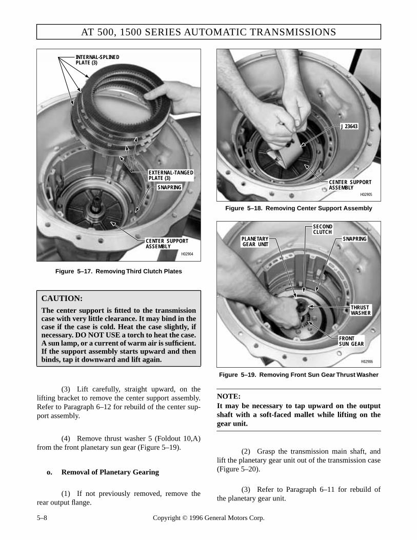
AT 500, 1500 SERIES AUTOMATIC TRANSMISSIONS
Figure 5–17. Removing Third Clutch Plates
(3) Lift carefully, straight upward, on thelifting bracket to remove the center support assembly.Refer to Paragraph 6–12 for rebuild of the center sup-port assembly.
(4) Remove thrust washer 5 (Foldout 10,A)from the front planetary sun gear (Figure 5–19).
o. Removal of Planetary Gearing
(1) If not previously removed, remove therear output flange.
CAUTION:
The center support is fitted to the transmissioncase with very little clearance. It may bind in thecase if the case is cold. Heat the case slightly, ifnecessary. DO NOT USE a torch to heat the case.A sun lamp, or a current of warm air is sufficient.If the support assembly starts upward and thenbinds, tap it downward and lift again.
H02904
CENTER SUPPORTASSEMBLY
SNAPRING
INTERNAL-SPLINEDPLATE (3)
EXTERNAL-TANGEDPLATE (3)
5–8 Copyright © 1996 Ge
Figure 5–18. Removing Center Support Assembly
Figure 5–19. Removing Front Sun Gear Thrust Washer
NOTE:It may be necessary to tap upward on the outputshaft with a soft-faced mallet while lifting on thegear unit.
(2) Grasp the transmission main shaft, andlift the planetary gear unit out of the transmission case(Figure 5–20).
(3) Refer to Paragraph 6–11 for rebuild ofthe planetary gear unit.
H02905
J 23643
CENTER SUPPORTASSEMBLY
H02906
SECONDCLUTCH
THRUSTWASHER
FRONTSUN GEAR
SNAPRINGPLANETARYGEAR UNIT
neral Motors Corp.

DISASSEMBLY OF TRANSMISSION
Figure 5–20. Removing Planetary Gear Unit
(4) Governor drive gear 1 (Foldout 12,B),speedometer drive gear 2 or speed sensor wheel 9, andspacer 3 may come out with the gear unit, or may stayin the transmission. Remove these parts.
p. Removal of Second Clutch
(1) Remove the snapring that retains the sec-ond clutch (Figure 5–21).
(2) Remove three external-tanged and threeinternal-splined second clutch plates (Figure 5–21).
(3) Remove the second clutch backplate(Figure 5–22).
q. Removal of First Clutch
(1) Remove snapring 1 (Foldout 10,B) thatretains first clutch backplate 2. Remove the backplate.
Figure 5–21. Removing Second Clutch Snapring
Figure 5–22. Removing Second Clutch Backplate
(2) Remove the ring gear and clutch pack asa unit from the main case. On earlier models, the rearring gear is part of the rear carrier assembly and is re-moved with the planetary gear unit.
(3) Install first clutch spring compressor as-sembly J 23630-02 (Figure 5–23). Tighten nutJ 23630-3 until the snapring is clear of the spring re-tainer.
CAUTION:
When removing the second clutch snapring, donot allow the snapring to drag across the ma-chined surface (surface with four holes throughit). Dragging the snapring may result in leaks be-tween the passages and/or leaks to the sump.
H02907
TRANSMISSIONMAIN SHAFT
PLANETARYGEAR UNIT
H02908
MACHINEDSURFACE
SNAPRING
SECOND CLUTCH
H02909
BACKPLATE
Copyright © 1996 General Motors Corp. 5–9

AT 500, 1500 SERIES AUTOMATIC TRANSMISSIONS
Figure 5–23. Removing First Clutch SpringRetainer Snapring
(4) Remove the snapring. Remove the com-pressor assembly.
(5) Remove the spring retainer and thetwenty-two piston return springs.
(6) Remove the first clutch piston (Figure5–23). Remove the two lip-type sealrings from thepiston.
Figure 5–24. Removing Output Shaft Bearing Snapring
r. Removal of Output Shaft Seal and Bearing
(1) Rotate the transmission so that the outputis upward. Remove output seal 6 (Foldout 12,B) fromthe rear of the transmission housing.
(2) Clean the bore from which the seal wasremoved.
(3) Remove the snapring that retains the out-put shaft bearing (Figure 5–24).
(4) Remove the bearing from its bore.
(5) Remove the transmission housing, withits remaining attached parts, from the transmissionholding fixture. Refer to Paragraph 6–14 for rebuild ofthe transmission housing.
WARNING!
When removing the first clutch snapring, do notallow the spring retainer to catch in the snapringgroove. Failure to observe this warning may re-sult in personal injury and damage to the springretainer.
H02910
SNAPRING
RETAINER
J 23630-02
J 23630-3
PISTON
H02911
SNAPRING
BEARING
5–10 Copyright © 1996 General Motors Corp.

Section 6 – REBUILD OF SUBASSEMBLIES
6–1. SCOPE
This section contains the rebuild procedures for thesubassemblies which were removed in Section 5.
6–2. GENERAL INFORMATION FOR SUBASSEMBLY REBUILD
Refer to Sections 4 and 8 for general overhaul infor-mation as follows:
6–3. INSPECTING AND TESTING TORQUE CONVERTER
NOTE:
Because the torque converter assembly for modelsother than the AT 543 is closed and welded after as-sembly of the internal parts, no repairs can bemade. The assembly can be tested, however, to de-termine its condition in two areas. End play of theinternal elements can be measured, and the outershell can be tested for leaks.
a. Preliminary Inspection. Clear the torqueconverter of transmission fluid. Examine the fluid forevidence of foreign matter or metal particles, indicat-ing transmission or converter internal damage.
b. End Play Check
(1) To check for end play, support the con-verter assembly on the converter cover (pump hub up-ward). Place converter end play gauge J 24602 into theconverter pump hub (Figure 6–1).
(2) Retain the body of the gauge in the pumphub with one hand while rotating the center screw withthe other hand, locking the gauge to the turbine hub.Do not overtighten.
(3) Assemble J 5959-1, J 5959-3, J 5959-7,J 7872-2, and J 7872-3 as shown in Figure 6–1. Installthe above items onto the converter pump hub asshown.
(4) Adjust lug attachment J 5959-7 so thedial will make firm contact with the top of end playgauge J 24602.
(5) Set the dial to read zero and lift J 24602as far as possible.
Figure 6–1. Checking End Play ofTorque Converter Element
Paragraph Description4–2 Tools and Equipment4–3 Replacement Parts4–4 Careful Handling4–5 Cleaning and Inspection4–6 Assembly Procedures
4–10 Torque Specifications8–1 Wear Limits Data8–2 Spring Data
CAUTION:
Allison Transmission Division GM recommendsonly genuine Allison torque converters for usewith any AT 500, 1500 Series Allison transmis-sions. Any transmission damage that may occuras a result of using a converter other than a newAllison converter or a genuine Allison replace-ment is the responsibility of the owner and willnot be covered by Allison warranty.
H02912
J 5959-1
J 24602
TORQUECONVERTER
J 5959-3
J 5959-7
J 7872-3
J 7872-2
Copyright © 1996 General Motors Corp. 6–1
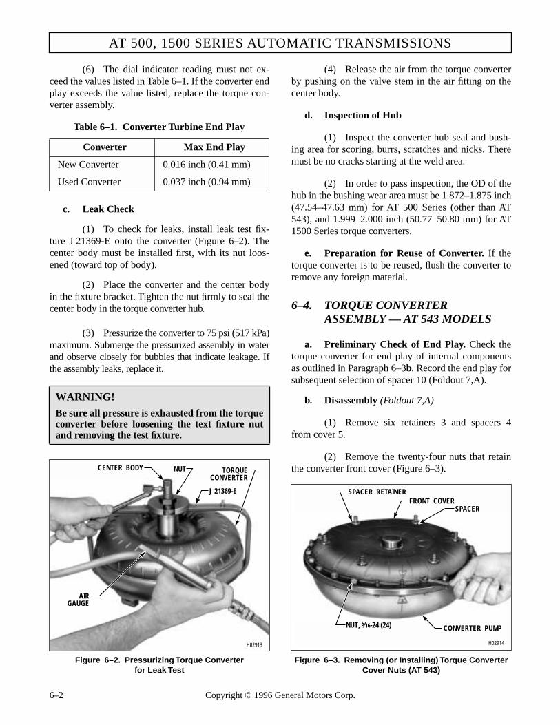
AT 500, 1500 SERIES AUTOMATIC TRANSMISSIONS
(6) The dial indicator reading must not ex-ceed the values listed in Table 6–1. If the converter endplay exceeds the value listed, replace the torque con-verter assembly.
c. Leak Check
(1) To check for leaks, install leak test fix-ture J 21369-E onto the converter (Figure 6–2). Thecenter body must be installed first, with its nut loos-ened (toward top of body).
(2) Place the converter and the center bodyin the fixture bracket. Tighten the nut firmly to seal thecenter body in the torque converter hub.
(3) Pressurize the converter to 75 psi (517 kPa)maximum. Submerge the pressurized assembly in waterand observe closely for bubbles that indicate leakage. Ifthe assembly leaks, replace it.
Figure 6–2. Pressurizing Torque Converterfor Leak Test
(4) Release the air from the torque converterby pushing on the valve stem in the air fitting on thecenter body.
d. Inspection of Hub
(1) Inspect the converter hub seal and bush-ing area for scoring, burrs, scratches and nicks. Theremust be no cracks starting at the weld area.
(2) In order to pass inspection, the OD of thehub in the bushing wear area must be 1.872–1.875 inch(47.54–47.63 mm) for AT 500 Series (other than AT543), and 1.999–2.000 inch (50.77–50.80 mm) for AT1500 Series torque converters.
e. Preparation for Reuse of Converter. If thetorque converter is to be reused, flush the converter toremove any foreign material.
6–4. TORQUE CONVERTERASSEMBLY — AT 543 MODELS
a. Preliminary Check of End Play. Check thetorque converter for end play of internal componentsas outlined in Paragraph 6–3b. Record the end play forsubsequent selection of spacer 10 (Foldout 7,A).
b. Disassembly (Foldout 7,A)
(1) Remove six retainers 3 and spacers 4from cover 5.
(2) Remove the twenty-four nuts that retainthe converter front cover (Figure 6–3).
Figure 6–3. Removing (or Installing) Torque Converter Cover Nuts (AT 543)
Table 6–1. Converter Turbine End Play
Converter Max End Play
New Converter 0.016 inch (0.41 mm)
Used Converter 0.037 inch (0.94 mm)
WARNING!
Be sure all pressure is exhausted from the torqueconverter before loosening the text fixture nutand removing the test fixture.
H02913
J 21369-E
NUT TORQUECONVERTER
CENTER BODY
AIRGAUGE
H02914
FRONT COVERSPACER
SPACER RETAINER
CONVERTER PUMPNUT, 5⁄16-24 (24)
6–2 Copyright © 1996 General Motors Corp.

REBUILD OF SUBASSEMBLIES
(3) Remove the front cover (Figure 6–4).Remove the front cover sealring.
(4) Remove two bearing races, bearing, andbearing spacer (Figure 6–5).
NOTE:
Some of these parts may have adhered to the coverwhen it was removed.
(5) Lift off the converter turbine (Figure 6–6).
(6) Lift off the stator assembly, using care thatthe freewheel roller race does not fall out (Figure 6–7).
Figure 6–4. Removing (or Installing) Torque Converter Cover (AT 543)
Figure 6–5. Removing (or Installing) Spacer, Bearing, and Races at Front of Torque Converter Turbine (AT 543)
(7) Position the stator assembly front down-ward, and remove the freewheel roller race by rotatingit clockwise while lifting.
(8) Remove ten rollers 26 (Foldout 7,A) andten springs 27.
(9) Thoroughly inspect needle bearing as-sembly 24. Wash and flush the needle bearing assem-bly thoroughly with mineral spirits. Dry the bearingand lubricate it with transmission fluid. Install free-wheel roller race 25 into stator and bearing assembly15. Rotate the stator and bearing assembly against thefreewheel race. If there is no roughness or binding, theneedle bearing assembly may be left in the stator andcam assembly and reused. Check the needle bearingend of freewheel race 25 for smooth finish. Replacefreewheel race 25 and bearing 24 if the bearing end ofthe race is scratched or contains chatter marks.
Figure 6–6. Removing (or Installing) TorqueConverter Turbine (AT 543)
Figure 6–7. Removing (or Installing) Torque Converter Stator Assembly (AT 543)
H02915
FRONT COVER
CONVERTER TURBINECONVERTER
PUMPBALANCE
MARK
BALANCE MARK
SEALRING
H02916
CONVERTER TURBINE
FRONT BEARING RACE
REAR BEARING RACETHRUST BEARING SPACER (SELECTIVE)
THRUST BEARING
CONVERTER PUMP
H02917
CONVERTER TURBINE
CONVERTER STATORASSEMBLY
CONVERTER PUMP
H02918
STATORASSEMBLY
CONVERTER PUMP
Copyright © 1996 General Motors Corp. 6–3

AT 500, 1500 SERIES AUTOMATIC TRANSMISSIONS
(10) Remove the needle bearing assembly andbearing race from the converter pump (Figure 6–8).
(11) Flatten the corners of lockstrips 29(Foldout 7,A). Remove eight bolts 28 and the lock-strips.
(12) Remove hub 30 and gasket 31 from con-verter pump 35.
(13) Do not remove bolts 36 unless new boltsare needed.
NOTE:
• If needle bearing assembly 24 needs replacementbut stator assembly 16 does not need to be re-placed, proceed to Paragraph 6–4c.
• If stator and bearing assembly 15 is damaged,replace the assembly.
c. Replacement of Needle BearingAssembly in Stator Assembly
(1) Place the stator assembly on a work tablefront side upward. Tap the bearing gently from itsbore. Do not nick or scratch the aluminum bore duringremoval.
Figure 6–8. Removing (or Installing) Torque Converter Pump Bearing and Race (AT 543)
(2) Place a new bearing assembly into thealuminum bore of the stator. Using bearing installertool J 23549 and handle J 24202-4, install the thrustbearing (Figure 6–9).
(3) Drive the bearing assembly to a height of0.025–0.035 inch (0.64–0.89 mm) above the shoulderin the side plate (Figure 6–10). The installing tool willseat on the stator area surrounding the bearing whenthe bearing is properly installed.
d. Assembly (Foldout 7,A)
(1) Install new gasket 31 onto converterpump 35. Install hub 30 into pump 35. Align the holesin the hub and gasket with the holes in the pump.
(2) Install four new lockstrips 29 and eight1⁄4-20 x 5⁄8 inch bolts 28 through hub 30 and into pump35. Tighten the bolts to 9–11 lb ft (12–15 N·m). Bendthe corners of the lockstrips against the bolt heads.
(3) Replace any converter pump flange bolts36 necessary and make sure any weights are in theiroriginal positions if pump bolts have been removed.
Figure 6–9. Installing Stator Thrust Bearing (AT 543)
CAUTION:
Do not scratch or nick any stator bores. Do notattempt to disassemble the stator and cam as-sembly unless replacement is required.
H02919
NEEDLE BEARINGASSEMBLY
BEARING RACE
CONVERTER PUMP
CAUTION:
Apply the load only to the outer shell of the bear-ing during installation (Figure 6–9).
J 24202-4
J 23549
BEARINGASSEMBLY
STATORH00349
6–4 Copyright © 1996 General Motors Corp.

REBUILD OF SUBASSEMBLIES
Figure 6–10. Stator Bearing Installation (AT 543)
Assemble withcam pockets inposition shown
Assembly load to beapplied in this areaon outer shell only
0.035 in. (0.89 mm)0.025 in. (0.64 mm)
BEARING
CAM
ENLARGED VIEWOF CROSS-SECTION
ENLARGED VIEWSECTION A-A
DEEP POCKET
STATOR VIEW AT B-B
A A
B
B
DIRECTION OFFREEWHEELROTATION
L00294
(4) Install the bearing race and needlebearing assembly into the converter pump hub (Fig-ure 6–8).
(5) Place the stator and bearing assemblyon the work table with the bearing side down (Fig-ure 6–11). Cover the bottoms of the stator campockets with oil-soluble grease. Install collapsibleretainer J 24218-1 with cord attached as shown inFigure 6–11.
(6) Install ten freewheel rollers and tensprings. The open end of the spring touching the rollermust be toward the center of the stator cam assembly(Figure 6–12). The rollers are installed in the shallowends of the cam pockets.
(7) Install the freewheel roller race, in theposition shown in Figure 6–11, until the race engagesthe rollers. Rotate the race in a clockwise directionwhile pressing downward until the race touches thecollapsible retainer. Lift up on the stator assembly andpull on the cord to remove the retainer. Continue rotat-ing the race while pressing downward. When the raceis fully seated, rotate it firmly in the opposite directionto lock the stator and cam assembly.
Figure 6–11. Installing Freewheel Roller Race (AT 543)
(8) Grasp the stator and cam assembly asshown in Figure 6–7 and install it onto the converterpump hub. Hold the roller race firmly to retain it in po-sition.
(9) Install the converter turbine assembly(Figure 6–6).
RETAINERJ 24218-1
SPRING
ROLLERROLLER RACE
NEEDLEBEARINGASSEMBLYSTATOR AND
CAM ASSEMBLYH00348
Copyright © 1996 General Motors Corp. 6–5

AT 500, 1500 SERIES AUTOMATIC TRANSMISSIONS
Figure 6–12. Spring and Roller in Stator Cam (AT 543)
NOTE:
If no parts were replaced with new parts that affectconverter end play (items 5, 11, 15, 25, 30, or 35 inFoldout 7,A) and if the end play recorded in Para-graph 6–4a was 0.025 inch (0.64 mm) maximum,proceed with Steps (10) through (17). If any of thelisted items were replaced or if the end play record-ed in Paragraph 6–4a was greater than 0.025 inch(0.64 mm), disregard Steps (10) through (17) andproceed with Steps (18) through (27).
(10) Install the same color selective thrustbearing spacer as was removed in Paragraph 6–4b(4)(Figure 6–5).
(11) Using transmission fluid, lubricate therear bearing race and install it, flat side first, onto thespacer (Figure 6–5).
(12) Lubricate the thrust bearing, and install itonto the bearing race (Figure 6–5).
(13) Using oil-soluble grease, install the frontbearing race, inner lip first, into the hub of convertercover 5 (Foldout 7,A).
(14) Install sealring 34 into the groove in theconverter pump (Figure 6–4).
(15) Install the converter cover onto the con-verter pump (Figure 6–4). The balance marks on thecover and pump must match.
(16) Install twenty-four nuts to retain the con-verter cover (Figure 6–3). Tighten four of the nuts, at90 degree intervals, to 10 lb ft (14 N.m). Then, tightenall the nuts to 19–23 lb ft (26–31 N.m).
(17) Install a spacer and a spacer retainer(earlier models) onto each of the six drive studs onthe converter cover (Figure 6–3). Recheck end playas outlined in Paragraph 6–3b. If end play does notexceed 0.025 inch (0.64 mm), repair is complete. Ifend play exceeds this limit, perform the steps in Para-graph 6–4b (1) through (4) and then proceed to Para-graph 6–4d(18).
(18) Install the rear bearing race (Figure 6–5),flat side first, onto the converter turbine (selectivespacer is omitted). The race should be dry.
(19) Install the thrust bearing (dry) onto therear race (Figure 6–5). Install the front bearing race(dry), inner lip upward, onto the thrust bearing.
NOTE:The measurements made in Steps (20) through (23)require that the gauge bar and blocks used (Figure6–13 through 6–16) be straight and smooth andhave parallel sides. The actual thickness of the barand height of blocks are immaterial, but the blocks,as pairs, must be of equal height.
(20) Position a bar and two blocks as shownin Figure 6–13. Using a depth micrometer, measurethe distance from the top of the bar to the machinedsurface of the converter cover hub. Record this Dimen-sion as A.
(21) Measure the distance from the top of thebar to the mounting surface of the converter cover (be-tween bolt holes) as shown in Figure 6–14. Record thisDimension as B.
(22) Position the bar and two blocks as shownin Figure 6–15. Measure the distance from the top ofthe bar to the mounting surface of the converter pump(between bolts). Record this Dimension as C.
(23) Measure the distance (Figure 6–16) fromthe top of the bar to the front bearing race installed inStep (19). Record this Dimension as D.
Roller to be installed insmall end of cam pocket
THRUST WASHER
STATOR CAM
RIVET
ROLLER
SPRING V02925
6–6 Copyright © 1996 General Motors Corp.

REBUILD OF SUBASSEMBLIES
Figure 6–13. Measuring Dimension A for Selection of Converter Spacer (AT 543)
Figure 6–14. Measuring Dimension B for Selection of Converter Spacer (AT 543)
Figure 6–15. Measuring Dimension C for Selection of Converter Spacer (AT 543)
(24) Using the dimensions recorded in Steps(20) through (23) in the formula X = (A–B) – (C–D),find X.
Figure 6–16. Measuring Dimension D for Selection of Converter Spacer (AT 543)
(25) From the following table, select theproper spacer.
(26) Remove the two bearing races and bearinginstalled in Steps (18) and (19). Install the selected spaceronto the torque converter pump hub (Figure 6–5).
(27) Complete the assembly of the torqueconverter by following Steps (11) through (17).
6–5. GOVERNOR
a. Disassembly (Foldout 12,A)
(1) Governor 18 may be disassembled forcleaning and inspection. Inspect governor driven gearfor scuffed, nicked, burred or broken teeth, any dam-age or wear will require governor assembly replace-ment. Do not disassemble the governor unless the kit
H02926
DEPTH MICROMETER
BLOCKBLOCKCONVERTER COVER
BAR,1 x 1 x 24 in.
H02927
DEPTH MICROMETER
BLOCKBLOCK
CONVERTER COVER
BAR,1 x 1 x 24 in.
H02928
DEPTH MICROMETER
BLOCK
BLOCK
CONVERTER PUMP CONVERTER TURBINE
BAR, 1 x 1 x 24 in.
X Use Part No. Color
0.017–0.034 inch 6837429 Gold(0.44–0.86 mm)0.034–0.049 inch 6837430 Silver(0.86–1.24 mm)0.049–0.062 inch 6837431 Plain(1.24–1.57 mm)0.062–0.079 inch 6837432 Black(1.57–2.00 mm)0.079–0.093 inch 6837433 Copper(2.00–2.36 mm)
H02929
DEPTH MICROMETER
BLOCK
BLOCK
NEEDLE THRUSTBEARING,
TWO RACES
CONVERTER PUMP CONVERTER TURBINE
BAR, 1 x 1 x 24 in.
Copyright © 1996 General Motors Corp. 6–7

AT 500, 1500 SERIES AUTOMATIC TRANSMISSIONS
consisting of two governor weight pins and the covergasket is available.
(2) Follow the directions furnished with thekit to disassemble the governor.
b. Assembly (Foldout 12,A)
(1) Assemble the governor as outlined in thedirections furnished with the governor service kit.
(2) Check the governor port openings as out-lined in the kit instructions. Refer to Figure 6–17.
6–6. MAIN CONTROL VALVE BODY
a. Disassembly (Foldout 11)
(1) Remove manual selector valve 53 fromcontrol valve body 11.
(2) Remove three bolts 3 from modulatorvalve body 10. Remove the valve body and separatorplate 2.
(3) Remove priority valve 45, spring 44, andvalve stop 43 from valve body 11.
(4) Compress adjusting ring 4 or 82 and re-move retainer pin 9.
Figure 6–17. Governor Assembly — ShowingPort Openings
Figure 6–18. Step Numbers for Recording the Positions of Adjusting Rings
(5) For some models, remove adjusting ring82, spring 7, modulator valve 81, and actuating rod 80.For other models, remove adjusting ring 4, stop 5,spring washer 6, spring 7, and modulator valve 8.
(6) Remove nine bolts 35 (eight, some mod-els) from trimmer cover 34. Remove trimmer cover 34.
(7) Remove from the bores in valve body11, spring 14, stop 15, plug 13, and third clutch trim-mer valve 12; springs 18 and 19 (if present), stop 20,plug 17, and first clutch trimmer valve 16; springs 23and 24 (if present), stop 25, plug 22, and second
CAUTION:
• Before removing retainer pins 9, 52, 59, 65,and 71, record the positions of adjusting rings4 or 82, 51, 58, 64, and 70 (Figure 6–18). Toretain the original calibration of the valve as-sembly, the adjusting rings must be rein-stalled in the same positions as whenremoved. Adjusting rings are spring-loaded.
• The main control valve body assembly con-tains springs and other parts, some of whichare similar and can be mistakenly inter-changed. If parts are not reinstalled in thesame locations from which they were re-moved, the calibration of valve body func-tions will be lost. Tag each part at removalwith its item number in Foldout 11 and utilizevalve body parts tray set J 33163 to simplifycorrect reassembly of the valve body compo-nents.
GOVERNOR FEED(Must open 0.020 in.
(0.51 mm) min)GOVERNOR PRESSUREPORTSEXHAUST PORTS
(Must open 0.020 in.(0.51 mm) min)
V02308
V02930
7
12
3
4
5
6
712
3
4
5
6
6–8 Copyright © 1996 General Motors Corp.

REBUILD OF SUBASSEMBLIES
clutch trimmer valve 21; and springs 31 and 32 (ifpresent), stop 33, plug 30, and fourth clutch trimmervalve 29. For models that do not have spring 32, dis-card spring 31 and install new springs 31 and 32.
(8) If present, remove accumulator valve 28,spring 27, and stop 26.
NOTE:
• For AT 545 models, S/N 3210418516 through3210419140 only, proceed with Step (9).
• For all other models, skip Step (9) and proceedwith NOTE preceding Step (10).
(9) For AT 545 models S/N 321041856through 3210419140 only, check the etched part num-ber on trimmer valves 12, 16, 21, and 29. Replace anyincorrect P/N 23016686 trimmer valves at reassemblywith the correct P/N 23014097 trimmer valves.
NOTE:
Valve stop 39 and spacer 42 are spring-loaded andmust be restrained while retainer pins 36 are beingremoved. (Valve stop 39 replaces two parts used inearlier models.)
(10) Remove one retainer pin 36 from controlvalve body 11. Remove spacer 42, spring 41, and 1–2relay valve 40.
(11) Examine the interior bore of 1–2 relayvalve 40. If the configuration of the valve matches
View A, Figure 6–19, discard the valve and replace itwith a new valve at reassembly.
(12) Remove the other retainer pin 36 fromcontrol valve body 11. Remove stop 39, spring 38, and2–3 relay valve 37.
(13) Compress adjusting ring 51 and removeretainer pin 52. Remove adjusting ring 51, washer 50,plug 49 (if present), valve stop 48, valve spring 47, andhold regulator valve 46 from the bore in control valvebody 11.
(14) Compress adjusting ring 58 and removeretainer pin 59. Remove adjusting ring 58, stop 57,spring 56 (if present), 1–2 modulator valve 55, 1–2shift signal valve 54, and spring 83 (if present).
(15) Compress adjusting ring 64 and removeretainer pin 65. Remove adjusting ring 64, stop 63,spring 62, 2–3 modulator valve 61, and 2–3 shift sig-nal valve 60.
NOTE:
Some units may have been field modified to preventthe 3–4 shift. Take note of the position of retainerpin 71 and stop 69; install parts in the same positionas removed.
(16) Compress adjusting ring 70 and removeretainer pin 71. Remove adjusting ring 70, stop 69,spring 68, 3–4 modulator valve 67, and 3–4 shift sig-nal valve 66.
Figure 6–19. 1–2 Relay Valve
Insufficient Bore Depth Drilling
VIEW A
RELAY VALVE
INCORRECT DRILLING, DOES NOTINTERSECT 0.125 in. (3.18 mm)EXHAUST PORT
VIEW BCORRECTLY DRILLED VALVE, DOESINTERSECT 0.125 in. (3.18 mm)EXHAUST PORT
0.125 in. (3.18 mm) EXHAUST PORT
Correct Bore Depth Drilling
0.125 in. (3.18 mm) EXHAUST PORT
V03135
Copyright © 1996 General Motors Corp. 6–9

AT 500, 1500 SERIES AUTOMATIC TRANSMISSIONS
(17) Restrain stop 74 and remove retainer pin75. Remove stop 74, spring 73, and 3–4 relay valve 72.Valve stop 74 replaces two parts used in earlier mod-els.
(18) If present, restrain stop 78 and removeretainer pin 79. Remove stop 78, spring 77, and trim-mer regulator valve 76.
b. Assembly (Foldout 11)
NOTE:
Check the configuration and position of all compo-nents (Figure 6–20). Check the identification of allsprings (Paragraph 8–2). All valves, when dry, mustmove freely by their own weight in their bores.
(1) Install 1–2 relay valve 40 (Foldout 11)into Bore A (Figure 6–20). Into the same bore, installspring 41 (Foldout 11) and spacer 42. Compressspacer 42 and install pin 36 through the valve bodyand at the outside end of spacer 42.
(2) Install 2–3 relay valve 37 into Bore B(Figure 6–20). Into the same bore, install spring 38(Foldout 11) and valve stop 39. Compress stop 39 andinstall pin 36 through the valve body and at the outsideend of stop 39.
(3) Install fourth clutch trimmer valve 29 intoBore C (Figure 6–20). Into the same bore, install plug30 (Foldout 11), springs 31 and 32 (if present), andvalve stop 33.
(4) Install second clutch trimmer valve 21into Bore D (Figure 6–20). Into the same bore, installplug 22 (Foldout 11), springs 23 and 24 (if present),and valve stop 25.
(5) Install third clutch trimmer valve 12 intoBore E (Figure 6–20). Into the same bore, install plug13 (Foldout 11), spring 14, and valve stop 15.
(6) Install first clutch trimmer valve 16 intoBore F (Figure 6–20). Into the same bore, install plug17 (Foldout 11), springs 18 and 19 (if present), andvalve stop 20.
(7) If removed, install spring 27 into Bore P(Figure 6–20). Into the same bore, install stop 26(Foldout 11) and accumulator valve 28.
(8) Install cover 34. Hold cover againstspring force and install nine (or eight, some mod-els) 1⁄4-20 x 3⁄4 inch bolts 35. Using preset torquewrench J 26912, tighten the bolts to 8–12 lb ft(11–16 N.m).
(9) If removed, install trimmer regulatorvalve 76 into Bore G (Figure 6–20). Into the samebore, install spring 77 (Foldout 11) and valve stop 78.Compress stop 78 and install retainer pin 79 throughthe valve body and through the hole in stop 78.
(10) Install 3–4 relay valve 72 into Bore H(Figure 6–20). Into the same bore, install spring 73(Foldout 11) and valve stop 74. Compress stop 74 andinstall pin 75 through the valve body and at the outsideend of stop 74.
(11) Install 3–4 shift signal valve 66 into BoreI (Figure 6–20). Into the same bore, install 3–4 modu-lator valve 67 (Foldout 11), spring 68, valve stop 69,and adjusting ring 70. Compress adjusting ring 70 andinstall retainer pin 71 as it was at removal.
(12) Install 2–3 shift signal valve 60 into BoreJ (Figure 6–20). Into the same bore, install 2–3 modu-lator valve 61 (Foldout 11), spring 62, valve stop 63,and adjusting ring 64. Compress adjusting ring 64 andinstall retainer pin 65 through the valve body, acrossthe recorded step of adjusting ring 64, and through thehole in stop 63.
(13) For units with second gear start, installspring 83 into Bore K (Figure 6–20). For all models,into Bore K, install 1–2 shift signal valve 54 (Foldout11). Into the same bore install 1–2 modulator valve 55.For units without second gear start, install spring 56.Install valve stop 57 and adjusting ring 58. Compressadjusting ring 58 and install retainer pin 59 throughthe valve body, across the recorded step of adjustingring 58, and through the hole in stop 57.
6–10 Copyright © 1996 General Motors Corp.
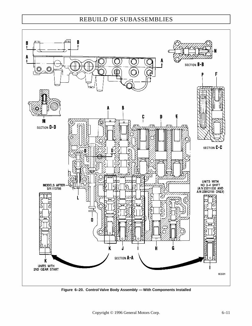
REBUILD OF SUBASSEMBLIES
Figure 6–20. Control Valve Body Assembly — With Components Installed
Copyright © 1996 General Motors Corp. 6–11

AT 500, 1500 SERIES AUTOMATIC TRANSMISSIONS
(14) Install hold regulator valve 46 into BoreL (Figure 6–20). Into the same bore, install spring 47(Foldout 11) and valve stop 48. Prior to transmissionS/N 113786, install valve plug 49. Beginning withtransmission S/N 113786, install washer 50 and ad-justing ring 51. Compress adjusting ring 51 and installretainer pin 52 through the valve body, across the re-corded step of adjusting ring 51, and through the holein stop 48.
(15) Install valve stop 43 into Bore M (Figure6–20). Into the same bore, install spring 44 (Foldout11) and priority valve 45.
(16) Into Bore N (Figure 6–20), install eithermodulator valve 8 (Foldout 11), spring 7, washer 6,stop 5, and adjusting ring 4; or, actuating rod 80, mod-ulator valve 81, spring 7, and adjusting ring 82. Com-press adjusting ring 4 or 82 and install retainer pin 9through the valve body, across the recorded step of ad-justing ring 4 or 82, and through the hold in stop 5 orat the outside end of valve 81.
(17) Install separator plate 2 onto valve body11. Install valve body 10 onto separator plate 2.
NOTE:Install six valve body bolts at various pointsthrough the separator plate and valve body to alignseparator plate.
(18) Install three 1⁄4-20 x 13⁄4 inch bolts 3 toretain valve body 10 and separator plate 2. Tighten thebolts to 8–12 lb ft (11–16 N·m). The assembled valvebody is shown in Figure 6–21.
(19) Install selector valve 53 (Foldout 11 intothe assembled valve body and retain it with a rubberband, tape, or soft wire to prevent its dropping out dur-ing handling.
(20) Use special tool J 24314, recheck the po-sitions of all adjusting rings (Figure 6–21) with the po-sitions recorded before disassembly.
(21) For ease of handling, install valve bodylifting tool J 29863 into the drilled boss in the centerof the valve body. Put the assembled valve body into aplastic bag or other dirt-proof, lint-free wrapping untilready to install it.
Figure 6–21. Adjusting Modulator Valve Ring
6–7. RETARDER CONTROLVALVE BODY
a. Disassembly (Foldout 13)
(1) Restrain plug 19 and remove pin 22.
(2) Remove plug 19, priority valve 20, andspring 21.
CAUTION:
The retarder control valve body assembly con-tains springs and other parts, some of which aresimilar and can be mistakenly interchanged. Ifparts are not reinstalled in the same locationsfrom which they were removed, the calibrationof retarder control valve body functions will belost. Tag each part at removal with its item num-ber in Foldout 13 to simplify correct reassemblyof the valve body components.
WARNING!
Priority valve 20 and plug 19 are spring-loadedand must be restrained while pin 22 is being re-moved.
WARNING!
Regulator valve 24 and plug 27 are spring-loadedand must be restrained while pin 22 is being re-moved.
H02932
MODULATOR VALVE
CONTROL VALVE
ADJUSTING RINGTOOL J 24314
GOVERNOR CHECK VALVEBALL (EARLIER MODELS)
6–12 Copyright © 1996 General Motors Corp.
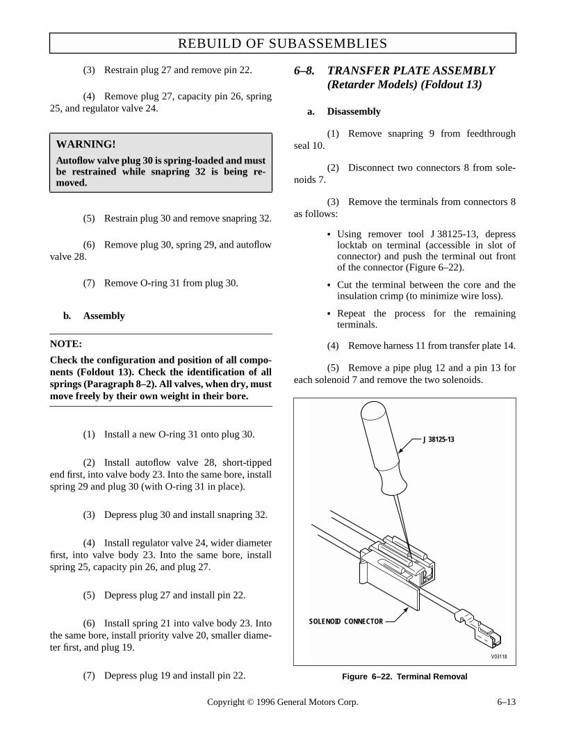
REBUILD OF SUBASSEMBLIES
(3) Restrain plug 27 and remove pin 22.
(4) Remove plug 27, capacity pin 26, spring25, and regulator valve 24.
(5) Restrain plug 30 and remove snapring 32.
(6) Remove plug 30, spring 29, and autoflowvalve 28.
(7) Remove O-ring 31 from plug 30.
b. Assembly
NOTE:
Check the configuration and position of all compo-nents (Foldout 13). Check the identification of allsprings (Paragraph 8–2). All valves, when dry, mustmove freely by their own weight in their bore.
(1) Install a new O-ring 31 onto plug 30.
(2) Install autoflow valve 28, short-tippedend first, into valve body 23. Into the same bore, installspring 29 and plug 30 (with O-ring 31 in place).
(3) Depress plug 30 and install snapring 32.
(4) Install regulator valve 24, wider diameterfirst, into valve body 23. Into the same bore, installspring 25, capacity pin 26, and plug 27.
(5) Depress plug 27 and install pin 22.
(6) Install spring 21 into valve body 23. Intothe same bore, install priority valve 20, smaller diame-ter first, and plug 19.
(7) Depress plug 19 and install pin 22.
6–8. TRANSFER PLATE ASSEMBLY (Retarder Models) (Foldout 13)
a. Disassembly
(1) Remove snapring 9 from feedthroughseal 10.
(2) Disconnect two connectors 8 from sole-noids 7.
(3) Remove the terminals from connectors 8as follows:
• Using remover tool J 38125-13, depresslocktab on terminal (accessible in slot ofconnector) and push the terminal out frontof the connector (Figure 6–22).
• Cut the terminal between the core and theinsulation crimp (to minimize wire loss).
• Repeat the process for the remainingterminals.
(4) Remove harness 11 from transfer plate 14.
(5) Remove a pipe plug 12 and a pin 13 foreach solenoid 7 and remove the two solenoids.
Figure 6–22. Terminal Removal
WARNING!
Autoflow valve plug 30 is spring-loaded and mustbe restrained while snapring 32 is being re-moved.
J 38125-13
V03118
SOLENOID CONNECTOR
Copyright © 1996 General Motors Corp. 6–13

AT 500, 1500 SERIES AUTOMATIC TRANSMISSIONS
(6) If present, remove pipe plug 15 (at thetemperature sending unit location) or, if present, re-move the temperature sending unit.
b. Assembly
(1) If removed, install 1⁄2-14 pipe plug 15.Tighten the plug to 16–20 lb ft (22–27 N.m).
(2) Place solenoids 7 in place in transferplate 14 and install pins 13. Install 1⁄16 inch pipe plugs12 to retain pins 13. Tighten plugs 12 to 35–50 lb in.(4–5 N.m).
(3) In preparation for installation of harness11, carefully strip wire insulation approximately 1⁄4inch (6 mm) (unless insulation crimp is over tight).Automatic wire stripper J 35615 will remove the insu-lation and crimp from the old terminal without damag-ing the wire.
(4) Install harness 11, fitting feedthroughseal 10 into transfer housing 14.
NOTE:
Terminals with white wires install in one connectorand terminals with red wires install in the otherconnector.
(5) Install the terminals onto connectors 8 asfollows:
• Place core crimp portion of terminal on bedof Anvil C on crimping tools J 38125-7 andsqueeze the crimper enough to hold theterminal from dropping (Figure 6–23).
• Position the wire core in the terminal andsqueeze the crimper tool to complete thecore crimp.
• Position the insulation crimp of the terminalon Anvil D so that the entire insulationcrimp area and a portion of the terminalbetween the core and insulation crimp areasare supported by the anvil. Complete theinsulation crimp.
• Slip the wire through the slot in theconnector and pull to fully seat theterminal(s).
Figure 6–23. Terminal Installation
(6) Install snapring 9 to retain the harness.
(7) Connect two connectors 8 until they snapinto place on two solenoids 7. The connector withwhite wires connects to the H (upper) solenoid; theconnector with the red wires connects to the F (lower)solenoid.
6–9. OIL PUMP AND FRONTSUPPORT ASSEMBLY
a. Disassembly (Foldout 7,B)
(1) Remove sealring 13 from front support 16.
(2) Remove six bolts 11 (eight, some mod-els) and washers 12 from the front of pump body 8.Discard the washers.
NOTE:
When removing bolts 28 and 29, if the five bolts areof two different lengths, take note of the size and lo-cation of the five bolts. The same size bolts will needto be installed as are removed.
A C E
BD
J 38125-7
V03119
6–14 Copyright © 1996 General Motors Corp.
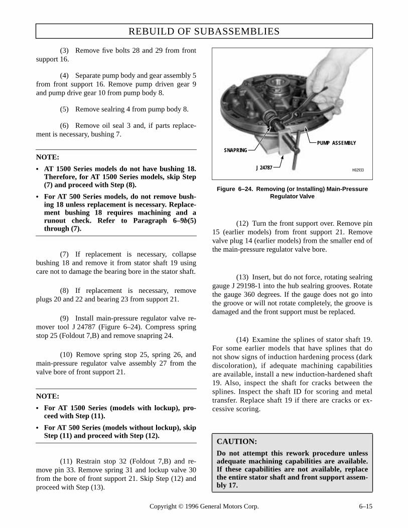
REBUILD OF SUBASSEMBLIES
(3) Remove five bolts 28 and 29 from frontsupport 16.
(4) Separate pump body and gear assembly 5from front support 16. Remove pump driven gear 9and pump drive gear 10 from pump body 8.
(5) Remove sealring 4 from pump body 8.
(6) Remove oil seal 3 and, if parts replace-ment is necessary, bushing 7.
NOTE:
• AT 1500 Series models do not have bushing 18.Therefore, for AT 1500 Series models, skip Step(7) and proceed with Step (8).
• For AT 500 Series models, do not remove bush-ing 18 unless replacement is necessary. Replace-ment bushing 18 requires machining and arunout check. Refer to Paragraph 6–9b(5)through (7).
(7) If replacement is necessary, collapsebushing 18 and remove it from stator shaft 19 usingcare not to damage the bearing bore in the stator shaft.
(8) If replacement is necessary, removeplugs 20 and 22 and bearing 23 from support 21.
(9) Install main-pressure regulator valve re-mover tool J 24787 (Figure 6–24). Compress springstop 25 (Foldout 7,B) and remove snapring 24.
(10) Remove spring stop 25, spring 26, andmain-pressure regulator valve assembly 27 from thevalve bore of front support 21.
NOTE:
• For AT 1500 Series (models with lockup), pro-ceed with Step (11).
• For AT 500 Series (models without lockup), skipStep (11) and proceed with Step (12).
(11) Restrain stop 32 (Foldout 7,B) and re-move pin 33. Remove spring 31 and lockup valve 30from the bore of front support 21. Skip Step (12) andproceed with Step (13).
Figure 6–24. Removing (or Installing) Main-Pressure Regulator Valve
(12) Turn the front support over. Remove pin15 (earlier models) from front support 21. Removevalve plug 14 (earlier models) from the smaller end ofthe main-pressure regulator valve bore.
(13) Insert, but do not force, rotating sealringgauge J 29198-1 into the hub sealring grooves. Rotatethe gauge 360 degrees. If the gauge does not go intothe groove or will not rotate completely, the groove isdamaged and the front support must be replaced.
(14) Examine the splines of stator shaft 19.For some earlier models that have splines that donot show signs of induction hardening process (darkdiscoloration), if adequate machining capabilitiesare available, install a new induction-hardened shaft19. Also, inspect the shaft for cracks between thesplines. Inspect the shaft ID for scoring and metaltransfer. Replace shaft 19 if there are cracks or ex-cessive scoring.
CAUTION:
Do not attempt this rework procedure unlessadequate machining capabilities are available.If these capabilities are not available, replacethe entire stator shaft and front support assem-bly 17.
H02933
PUMP ASSEMBLY
J 24787
SNAPRING
Copyright © 1996 General Motors Corp. 6–15

AT 500, 1500 SERIES AUTOMATIC TRANSMISSIONS
NOTE:
• If stator shaft 19 does not require being re-placed, skip Step (15) and Paragraph 6–8b andproceed with Paragraph 6–8c.
• If stator shaft 19 is to be replaced, proceed withStep (15).
(15) Put front support 21 in a press bed, ma-chined face downward, and press shaft 19 from frontsupport 21. Proceed with Paragraph 6–8b for shaft andbushing replacement and machining instructions.
b. Installation of Stator Shaft and Bushing (Foldout 7,B)
(1) Support the front support in a press withthe pump face upward.
(2) Position the stator shaft in the center boreof the front support, aligning the hole in the statorshaft within Angle K (Figure 6–25 or 6–26).
Figure 6–25. Installation of Stator Shaft, Machining of Bushing and Bearing Bores (AT 500 Series)
6–16 Copyright © 1996 Ge
(3) Press the stator shaft into the front sup-port to Dimension M as measured from Surface B tothe end of the stator shaft (Surface L) (Figure 6–25or 6–26). Axis A is established by Diameter D andSurface B. When mounted on Diameter D and Sur-face B, features shall be within the total runout speci-fied by H.
(4) Observe specifications for machining Di-ameters E and G.
NOTE:
AT 1500 Series models do not require bushing 18(Foldout 7,B). Therefore, for AT 1500 Series mod-els, skip Steps (5) through (7).
CAUTION:
Be sure to use the correct P/N replacement bush-ing. Refer to Parts Catalog PC1235EN.
neral Motors Corp.

REBUILD OF SUBASSEMBLIES
(5) Coat the OD of a new non-prebored re-placement bushing 18 (Foldout 7,B) with Loctite® 601sleeve retainer, or equivalent. Install bushing 18 intothe stator shaft with J 23614-A to a depth of flush to0.005 inch (0.127 mm) below the end of the shaft (Fig-ure 6–27). Remove any excess Loctite® from the shafthousing.
(6) Machine the bushing to the diameter andmicrofinish specified (Figure 6–25) while maintainingTIR not to exceed 0.003 inch (0.076 mm).
(7) Thoroughly clean the assembly of anymetal chips and dirt, being careful to clean all pas-sages in the front support.
c. Pump Gear Clearance Check (Foldout 7,B)
NOTE:
Proper end play and side clearance of the oil pumpgears must be established before the pump is assem-bled. Remove all nicks and burrs from the pumpand gear surfaces to facilitate accurate dial indica-tor readings.
Copyright © 1996 Ge
(1) Position oil pump body assembly 6, flatside upward. Install drive gear 10 into pump body as-sembly 6, so the internal tangs of the gear are facingupward. Install gear 9 into the pump body 6 so thatthe side of gear 9 marked with a diamond is down-ward.
(2) Position dial indicator J 26857 on thepump body as shown in Figure 6–28. Zero the dial whilethe stylus (plunger) is contacting the pump body face.
(3) Without disturbing the dial setting, slidethe indicator to the driven gear (Figure 6–29). Whileholding the indicator in position, record the reading. Ifthe clearance is not within 0.0008–0.0022 inch(0.020–0.056 mm) on a new gear or 0.0008–0.0026inch (0.020–0.066 mm) on a used gear, replace thegear and repeat Steps (2) and (3).
(4) Slide the indicator to the drive gear (Fig-ure 6–30). While holding the indicator in position,record the reading. If the clearance is not within0.0008–0.0022 inch (0.020–0.056 mm) on a new gearor 0.0008–0.0026 inch (0.020–0.066 mm) on a usedgear, replace the gear and repeat Steps (2) and (4).
Figure 6–26. Installation of Stator Shaft (AT 1500 Series)
neral Motors Corp. 6–17
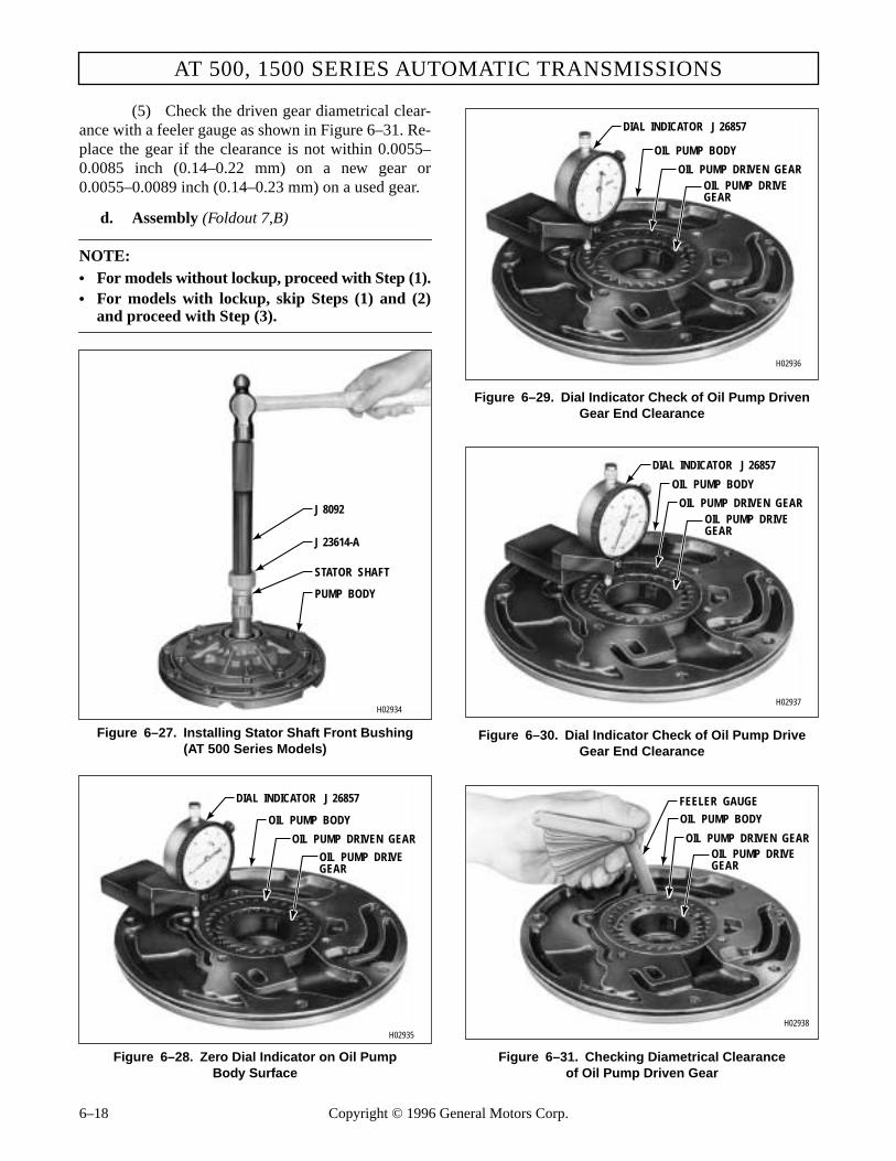
AT 500, 1500 SERIES AUTOMATIC TRANSMISSIONS
(5) Check the driven gear diametrical clear-ance with a feeler gauge as shown in Figure 6–31. Re-place the gear if the clearance is not within 0.0055–0.0085 inch (0.14–0.22 mm) on a new gear or0.0055–0.0089 inch (0.14–0.23 mm) on a used gear.
d. Assembly (Foldout 7,B)
NOTE:• For models without lockup, proceed with Step (1).• For models with lockup, skip Steps (1) and (2)
and proceed with Step (3).
Figure 6–27. Installing Stator Shaft Front Bushing(AT 500 Series Models)
Figure 6–28. Zero Dial Indicator on Oil PumpBody Surface
Figure 6–29. Dial Indicator Check of Oil Pump Driven Gear End Clearance
Figure 6–30. Dial Indicator Check of Oil Pump Drive Gear End Clearance
Figure 6–31. Checking Diametrical Clearanceof Oil Pump Driven Gear
H02934
PUMP BODY
STATOR SHAFT
J 23614-A
J 8092
H02935
OIL PUMP DRIVEGEAR
OIL PUMP DRIVEN GEAR
OIL PUMP BODY
DIAL INDICATOR J 26857
H02936
OIL PUMP DRIVEGEAR
OIL PUMP DRIVEN GEAR
OIL PUMP BODY
DIAL INDICATOR J 26857
H02937
OIL PUMP DRIVEGEAR
OIL PUMP DRIVEN GEAR
OIL PUMP BODY
DIAL INDICATOR J 26857
H02938
OIL PUMP DRIVEGEAR
OIL PUMP DRIVEN GEAR
OIL PUMP BODY
FEELER GAUGE
6–18 Copyright © 1996 General Motors Corp.

REBUILD OF SUBASSEMBLIES
(1) For models without lockup, if roller bear-ing 23 was removed, using installer J 23615, press onthe lettered end of the new bearing to a depth of0.595–0.615 inch (15.11–15.62 mm) from the end ofthe shaft (Figure 6–32).
(2) Install valve plug 14 (earlier models) intothe main pressure regulator valve bore of front support21. Install pin 15 (earlier models) into the pump bodyside of front support 21. Skip Step (3) and proceedwith Step (4).
(3) For models with lockup, if roller bearing23 was removed, using installer J 39794, press on thelettered end of the new bearing to a depth of 0.625–0.635 inch (15.88–16.12 mm) from the end of theshaft.
(4) Install main-pressure regulator valve 27,smaller end first, into its valve bore.
(5) Into the same bore, install valve spring26 and spring stop 25 (smaller end first).
(6) Install main-pressure regulator valve in-staller tool J 24787 (Figure 6–24). Restrain spring stop25 (Foldout 7,B) and install snapring 24, flat side out-ward. Remove the tool from the assembly.
Figure 6–32. Installing Stator Shaft Rear Bearing(Models without Lockup)
NOTE:• For models without lockup, skip Step (7) and
proceed with Step (8). • For models with lockup, proceed with Step (7).
(7) For models with lockup, install lockupvalve 30 (Foldout 7,B), smaller end first, into pump as-sembly 16. Into the same bore install spring 31 andstop 32. Restrain stop 32 and install pin 33 through themachined side of the front support.
(8) If either plug 20 or 22 was removed, in-stall a new plug. Press plug 20 into the support to adepth of flush to 0.010 inch (0.25 mm) below the sur-face. Press plug 22 to the shoulder in the support.
NOTE:• For models without lockup, proceed with
Step (9). • For models with lockup, skip Steps (9) and (10),
and proceed with Step (11).
(9) For models without lockup, if bushing 7was removed, install a new bushing. The split in thebushing must be located in an area of the bore that cancompletely support it. Use installer tool J 25356 topress the bushing into the front of the pump body to aheight of 0.010–0.020 inch (0.25–0.51 mm) above thesurface.
(10) Using special installer tool J 21359-A,install oil seal 3, with the lip facing inward (Figure6–33). Skip Steps (11) and (12) and proceed withStep (13).
(11) For models with lockup, if bushing 7 wasremoved, install a new bushing. The split in the bush-ing must be located in an area of the bore that cancompletely support it. Use installer tool J 39739 topress the bushing into the front of the pump body to adepth of flush to 0.398 inch (10.11 mm).
(12) Using special installer tool J 39757, in-stall oil seal 3 with the lip facing inward (Figure 6–33).
(13) Lubricate and install sealring 4 (Foldout7,B) onto pump body 8. Lubricate and install drivengear 9 and drive gear 10.
H02939
PUMP ASSEMBLY
J 23615
J 8092
Copyright © 1996 General Motors Corp. 6–19

AT 500, 1500 SERIES AUTOMATIC TRANSMISSIONS
(14) Install front support assembly 16 ontopump body assembly 5, aligning the bolt holes.
(15) Install six (eight, some models) 5⁄16-18 x1 inch bolts 11 (Foldout 7,B) and new rubber coatedwashers 12 into the pump side of the oil pump assem-bly. Tighten the bolts finger tight.
Figure 6–33. Installing Oil Pump Seal
Figure 6–34. Rework Dimensions for Front Support
(16) Install bolts 28 and 29 as were removed.(For different models, the length may differ).
(17) Tighten all the 5⁄16-18 bolts to 15–20 lb ft(20–27 N.m).
(18) Lubricate and install sealring 13 onto theouter diameter of front support 21.
6–10. FORWARD CLUTCH AND TURBINE SHAFT ASSEMBLY
a. Disassembly
NOTE:• For earlier models with PTO gear and without
retarder, proceed with Step (1).• For later models with PTO gear and without re-
tarder, skip Step (1) and proceed with Step (2)• For models without PTO gear and without re-
tarder, skip Steps (1) through (8) and proceedwith Step (9).
• For models with retarder, skip Steps (1) through(7) and proceed with Step (8).
(1) For earlier models with PTO gear andwithout retarder, place forward clutch and turbineshaft assembly 7 (Foldout 8) on the work table, withthe shaft upward. Using a screwdriver, removesnapring 3 that secures PTO drive gear 4 to forwardclutch housing 9. Remove gear 4 and snapring 5. SkipSteps (2) through (7) and proceed with Step (8).
(2) For later models with PTO gear andwithout retarder, locate the snapring gap by lookingbetween the tips of the PTO gear internal splines andthe roots of the housing splines. Light can be seen inthe gap area.
(3) At the opening (omitted housing spline)closest to the snapring gap, insert a small screwdriverand push the snapring toward the housing until a 5⁄64 x0.020 inch (2 x 0.5 mm) steel strip, 2 to 3 inches (50–75mm) long can be inserted in the root of the housingspline nearest the snapring gap (Figure 6–35).
(4) Repeat Step (3) at the opposite side ofthe snapring gap.
CAUTION:
Because of transmission fluid leakage, a six-boltsupport should never be used with an eight-boltpump body. However, the six-bolt support maybe modified by tapping two additional holes (Fig-ure 6–34). Any other combination of parts (6-hole support with 6-hole body, 8-hole supportwith 8-hole body, or 8-hole support with 6-holebody) is acceptable without modification.
H02940
PUMP BODY
J 21359-A, AT 500 SERIES(J 39757, AT 1500 SERIES)
L02941
Drill and tap to 0.3125-18UNC-2B two (2) places,locate within 0.010 in.(0.25 mm) radius of thetrue position given
3.740 in.(94.99 mm)
5.036 in.(127.91 mm)
2.900 in.(73.66 mm)
1.760 in.(44.70 mm)
2.920 in.(74.17 mm)
0.980 in.(24.89 mm)
REAR VIEW
6–20 Copyright © 1996 General Motors Corp.

REBUILD OF SUBASSEMBLIES
Figure 6–35. Removing PTO Gear FromForward Clutch Housing
(Later Models Without Retarder)
(5) Using the screwdriver in the openings(omitted splines) as required to depress the snapring,place steel strips in housing spline roots as necessaryto hold the snapring inward. Work from the strips firstinstalled to a point opposite the gap.
(6) Use as many strips as required (8 shouldbe sufficient) and place them at positions that will holdthe snapring entirely clear of the PTO gear splines.
(7) When the snapring clears the PTO gearsplines, light can be seen through all spaces (exceptthose holding steel strips) between PTO gear splinetips and housing spline roots. Remove the gear.
(8) For models with retarder, remove twohook-type sealrings 12 (Foldout 8) from forwardclutch housing 14.
(9) Remove hook-type sealring 2 (Foldout 8)from the turbine shaft. Turn the assembly over.
(10) Using a screwdriver, remove snapring 30from the forward clutch housing. Remove fourthclutch drive hub 29 from the housing.
(11) Remove forward clutch hub 26 from thehousing.
(12) Inspect forward clutch hub 26 closely onhigh mileage transmission units down for overhaul.Over an extended period of operation, a wear pattern
at the internal spline of the hub may occur. This wearring, the result of contact with the transmission mainshaft, is so uniform in shape that it is often overlooked.Replace this hub where this condition exists. In mostinstances, wear of adjacent thrust washers should alertyou to inspect the forward clutch hub for abnormalwear. Although the transmission may be functioningproperly prior to overhaul, the clutch hub should be re-placed when wear exists. Reuse of a distressed hubwith new washers will accelerate washer wear and willnot duplicate the original durability and service life.
(13) Remove thrust bearing race 25, thrustneedle bearing 24, and thrust bearing race 23 from thehub of the forward clutch housing.
(14) Remove five external-tanged clutchplates 27 and five internal-splined clutch plates 28from the clutch housing.
NOTE:
• Later models have a wave plate in the forwardclutch next to piston 19 (Foldout 8) which im-proves the neutral-to-range shift quality. A kit isavailable that contains parts required to makethis change. Be sure to confirm all interchange-ability factors by referring to Parts CatalogSA1235 or SA2126. Both forward- and fourth-clutch assemblies have various part numbers af-fected by this upgrade. Refer also to the latestversion of Service Information Letter 3-TR-93.
• Models that have the wave plate in the forwardclutch assembly use a clutch housing markedwith an identification groove (Figure 6–36).
(15) Place the forward clutch assembly in apress with the spring retainer upward (Figure 6–37).
(16) Place compressor tool J 23616 on thespring retainer (Figure 6–37). Compress the retaineruntil the snapring is free. Using snapring pliers, re-move the snapring. Release the press and remove theassembly.
L02942
FORWARDCLUTCH HOUSING
PTOGEAR
SHIM 2
SHIM 1
SHIM 3
SHIM 5SHIM 7
SHIM 8
SHIM 6
SHIM 4
SNAPRING SNAPRINGGAP
CAUTION:
When removing the forward clutch snapring, donot allow the spring retainer to catch in thesnapring groove.
Copyright © 1996 General Motors Corp. 6–21
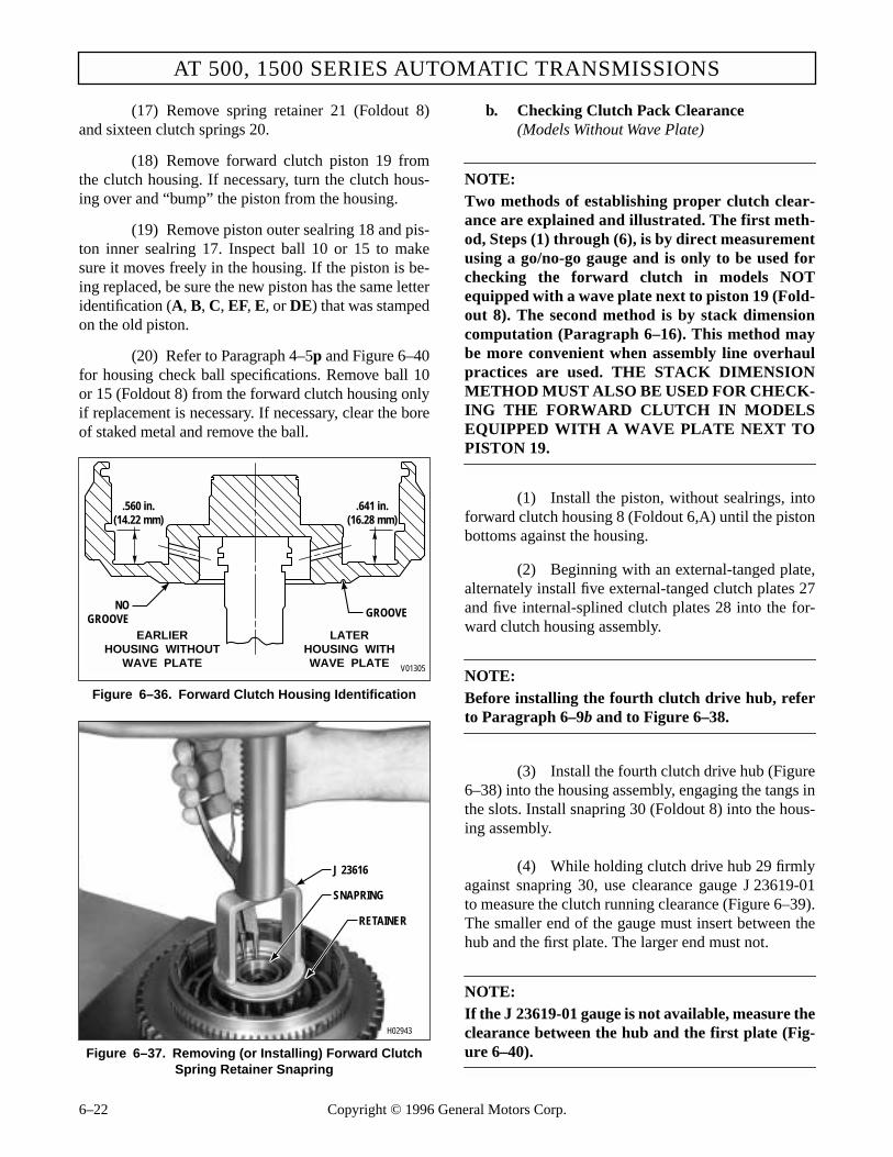
AT 500, 1500 SERIES AUTOMATIC TRANSMISSIONS
(17) Remove spring retainer 21 (Foldout 8)and sixteen clutch springs 20.
(18) Remove forward clutch piston 19 fromthe clutch housing. If necessary, turn the clutch hous-ing over and “bump” the piston from the housing.
(19) Remove piston outer sealring 18 and pis-ton inner sealring 17. Inspect ball 10 or 15 to makesure it moves freely in the housing. If the piston is be-ing replaced, be sure the new piston has the same letteridentification (A, B, C, EF, E, or DE) that was stampedon the old piston.
(20) Refer to Paragraph 4–5p and Figure 6–40for housing check ball specifications. Remove ball 10or 15 (Foldout 8) from the forward clutch housing onlyif replacement is necessary. If necessary, clear the boreof staked metal and remove the ball.
Figure 6–36. Forward Clutch Housing Identification
Figure 6–37. Removing (or Installing) Forward Clutch Spring Retainer Snapring
b. Checking Clutch Pack Clearance(Models Without Wave Plate)
NOTE:Two methods of establishing proper clutch clear-ance are explained and illustrated. The first meth-od, Steps (1) through (6), is by direct measurementusing a go/no-go gauge and is only to be used forchecking the forward clutch in models NOTequipped with a wave plate next to piston 19 (Fold-out 8). The second method is by stack dimensioncomputation (Paragraph 6–16). This method maybe more convenient when assembly line overhaulpractices are used. THE STACK DIMENSIONMETHOD MUST ALSO BE USED FOR CHECK-ING THE FORWARD CLUTCH IN MODELSEQUIPPED WITH A WAVE PLATE NEXT TOPISTON 19.
(1) Install the piston, without sealrings, intoforward clutch housing 8 (Foldout 6,A) until the pistonbottoms against the housing.
(2) Beginning with an external-tanged plate,alternately install five external-tanged clutch plates 27and five internal-splined clutch plates 28 into the for-ward clutch housing assembly.
NOTE:Before installing the fourth clutch drive hub, referto Paragraph 6–9b and to Figure 6–38.
(3) Install the fourth clutch drive hub (Figure6–38) into the housing assembly, engaging the tangs inthe slots. Install snapring 30 (Foldout 8) into the hous-ing assembly.
(4) While holding clutch drive hub 29 firmlyagainst snapring 30, use clearance gauge J 23619-01to measure the clutch running clearance (Figure 6–39).The smaller end of the gauge must insert between thehub and the first plate. The larger end must not.
NOTE:If the J 23619-01 gauge is not available, measure theclearance between the hub and the first plate (Fig-ure 6–40).
LATERHOUSING WITHWAVE PLATE
EARLIERHOUSING WITHOUT
WAVE PLATE
.560 in.(14.22 mm)
.641 in.(16.28 mm)
V01305
GROOVENO
GROOVE
H02943
J 23616
SNAPRING
RETAINER
6–22 Copyright © 1996 General Motors Corp.

REBUILD OF SUBASSEMBLIES
Figure 6–38. Fourth Clutch Drive Hub Identification
2.005 in.(50.93 mm)
2.043 in.(51.89 mm)
“9661”STAMPED
LATER HUBEARLIER HUBV02945
(5) If the clutch running clearance is notwithin the specified limits, remove snapring 30, fourthclutch drive hub 29, and clutch plates 27 and 28. Re-place clutch plates 27 and 28 with new plates or newpiston, as required, to obtain the desired running clear-ance. Refer to wear limits, Section 8, to determine theplates which should be replaced.
(6) Repeat Steps (2), (3), (4), and (5). Whenthe running clearance is within 0.0765–0.1265 inch(1.944–3.213 mm), remove snapring 30, drive hub 29,clutch plates 27 and 28, and piston 19. Keep the clutchplates together as a package until required.
Figure 6–39. Checking Forward Clutch Clearance(Models Without Wave Plate)
H02946
FORWARDCLUTCH AND
TURBINE SHAFTASSEMBLY
FOURTH CLUTCHDRIVE HUB
J 23619-01
Copyright © 1996 Ge
neral Motors Corp. 6–23c. Assembly (Foldout 8)
(1) If ball 10 or 15 was removed, place thenew ball into the bore. Stake the bore at three equallyspaced locations. The bore is properly staked when theball has the minimum axial movement specified inFigure 6–40 and when the ball is retained by the stak-ing when a 30 lb (133 N) load is applied against theball.
(2) Install sixteen return springs 20 (Foldout8) into their pockets in the piston (Figure 6–41). Installthe spring retainer, recess side first, onto the springs.
(3) Place the clutch assembly in a press,spring retainer upward. Lay snapring 22 (Foldout 8)in its approximate installed position on spring re-tainer 21.
Figure 6–40. Forward Clutch Clearance Check Point (Models Without Wave Plate)
��������
������
V02947
Minimum Axial Movement0.040 in. (1.02mm)
Check clearance here0.0765 – 0.1265 in.(1.944 – 3.213 mm)

AT 500, 1500 SERIES AUTOMATIC TRANSMISSIONS
(4) Using compressor tool J 23616, com-press the spring retainer until it clears the snapringgroove in the housing hub (Figure 6–37). Installsnapring 22 (Foldout 8) into the groove in the hub inthe clutch housing assembly. Release the press and re-move the clutch housing assembly.
(5) Install the flat bearing race onto the hubof the forward clutch housing (Figure 6–41). Installthe thrust needle bearing and the lipped bearing raceso that it encloses the bearing. Retain the bearing andraces with oil-soluble grease.
(6) Install the forward clutch hub into theclutch housing (Figure 6–42).
NOTE:
• For models with a wave plate next to piston 19(Foldout 8), proceed with Step (7).
• For models not equipped with a wave plate next topiston 19, skip Step (7) and proceed with Step (8).
(7) Install the clutch pack established inParagraph 6–17b(3). Begin by placing the wave platenext to piston 19 (Foldout 8). Then alternately installfive internal-splined and the remaining four external-tanged clutch plates into the forward clutch housingassembly. Skip Step (8) and proceed with Step (9).
Figure 6–41. Installing Forward Clutch Thrust Bearing
(8) Beginning with an external-tanged clutchplate, install the clutch pack established in Paragraph6–9c(6) or 6–17b(3) (Figure 6–42).
(9) Install the fourth clutch drive hub (Figure6–39) into the housing assembly and secure the hubwith snapring 30 (Foldout 8).
NOTE:
• For assembly of the PTO gear for later modelsdo Steps (10) through (13) and Step (17).
• For assembly of the PTO gear for earlier models,skip Steps (10) through (13), and do Steps (14)through (17).
• For non-retarder models that do not include aPTO gear, skip Steps (10) through (16) and doStep (17) only.
• For retarder models, skip Steps (10) through(16) and do Steps (17) and (18).
(10) For later models, place forward clutchhousing and turbine assembly 7 (Foldout 8) on thework table, shaft downward.
(11) Install snapring 31 into the snapringgroove in forward clutch housing 9.
Figure 6–42. Installing Forward Clutch Plates(Models Without Wave Plate)
CAUTION:
When installing the forward clutch snapring, donot allow the spring retainer to catch in thesnapring groove.
H02948
SPRING (16)
SPRING RETAINER
BEARING RACE (FLAT)
BEARING RACE (LIPPED) THRUST BEARING
H02949
EXTERNAL-TANGEDPLATE (5)
INTERNAL-SPLINED
PLATE (5)
CLUTCHHOUSING
CLUTCH HUB
6–24 Copyright © 1996 General Motors Corp.

REBUILD OF SUBASSEMBLIES
(12) Place PTO gear 32 onto the forwardclutch housing. Be sure the chamfer on the inside di-ameter of the PTO gear is facing downward.
(13) Compress snapring 31 into the clutchhousing and install the PTO gear. Be sure the gear ispositioned so that the snapring expands into the gear.Proceed to Step (17).
(14) For earlier models, install wave-typesnapring 5 (Foldout 8) onto forward clutch housing 9.Be sure the tips of the snapring face the PTO gear.
(15) Install PTO drive gear 4 (flat side towardfront of transmission), from the turbine shaft side, un-til it is firmly seated against snapring 5.
(16) Install snapring 3 onto housing 9 to se-cure gear 4.
(17) Install hook-type sealring 2 onto the tur-bine shaft.
(18) For models with retarder, install twohook-type sealrings 12 onto forward clutch housing 14.
6–11. RETARDER HOUSING ASSEMBLY
a. Disassembly
(1) Place retarder housing assembly 34(Foldout 8) on the work table with the screw side fac-ing upward.
(2) Remove four screws 37.
(3) Separate rear stator 35 from retarderhousing 36.
(4) Visually inspect that all fluid passageholes are clean and free of debris.
b. Assembly
(1) Place rear stator 35 in place in retarderhousing 36, aligning the bolt holes. Start one screw 37to establish alignment.
(2) Install the remaining three screws 37.Tighten all four screws to 10–12 lb ft (14–16 N·m).
6–12. FOURTH CLUTCH ASSEMBLY
a. Disassembly (Foldout 9,A)
(1) Place the fourth clutch on the work table,with snapring 1 upward. Remove snapring 1, back-plate 2, five internal-splined clutch plates 3, and fiveexternal-tanged clutch plates 4.
(2) Place fourth clutch housing assembly 11in a press (Figure 6–43).
(3) Using spring compressor J 23616, com-press piston return spring retainer 6 and removesnapring 5 and spring retainer 6.
(4) Remove sixteen piston return springs 7and remove fourth clutch piston 8.
(5) Remove sealring 9 from the OD of pis-ton 8. Remove sealring 10 from the ID of piston 8.Check the sealring groove thoroughly for burrs andrough spots.
Figure 6–43. Removing (or Installing) Fourth Clutch Spring Retainer Snapring
CAUTION:
When removing the fourth clutch snapring, donot allow the spring retainer to catch in thesnapring groove.
H02950
J 23616
HOUSING
SPRING (16)
RETAINER
SNAPRING
Copyright © 1996 General Motors Corp. 6–25

AT 500, 1500 SERIES AUTOMATIC TRANSMISSIONS
NOTE:
Earlier model transmissions use a piston seal onfourth clutch housing 13. If present, discard thehousing seal. A fourth clutch housing seal shouldnot be used during assembly. Use only the two sealson the piston.
(6) Refer to Paragraph 4–5p and Figure 6–45for housing check ball specifications. Remove the ballfrom the fourth clutch housing only if replacement isnecessary. If necessary, clear the bore of the stakedmetal and remove the ball.
b. Checking Clutch Pack Clearance
NOTE:
• Two methods of establishing proper clutch clear-ance are explained and illustrated. The firstmethod, Steps (1) through (6), is by direct mea-surement using a go/no-go gauge. The secondmethod is by stack dimension computation(Paragraph 6–17). This method may be moreconvenient when assembly line overhaul practic-es are used.
• If piston 8 must be replaced, be sure that theidentification (A, B, C, EF, E, or DE) on the newpiston is the same as that on the old piston.
(1) Install the piston, without sealrings, intothe clutch housing assembly until the piston bottomsagainst the housing.
(2) Beginning with an external-tanged plate,alternately install five external-tanged clutch plates 4(Foldout 9,A) and five internal-splined clutch plates 3onto piston 8.
(3) Install clutch backplate 2, flat side first,onto the last clutch plate 3 installed. Install snapring 1into housing 13.
(4) While holding backplate 2 firmly againstsnapring 1, use clutch clearance gauge J 23619-01 tomeasure the clearance between the backplate and theclutch plate (Figure 6–44). The smaller end of thegauge must insert between the backplate and the firstclutch plate. The larger end must not.
NOTE:
If the J 23619-01 gauge is not available, measure theclearance between the backplate and the first clutchplate (Figure 6–45).
(5) If the clutch running clearance is notwithin the specified limits, remove snapring 1, back-plate 2, and clutch plates 3 and 4. Replace clutchplates 3 and 4 with new plates or replace piston, as re-quired, to establish the proper running clearance. Re-fer to wear limits, Section 8, to determine the plateswhich should be replaced.
Figure 6–44. Checking Fourth Clutch Clearance
Figure 6–45. Fourth Clutch Clearance Check Point
H02951
J 23619-01
BACKPLATE
FOURTHCLUTCH
ASSEMBLY
V02952
Minimum Axial Movement0.040 in. (1.02 mm)
Check clearance here0.0765 – 0.1265 in.(1.944 – 3.213 mm)
��������������
BACKPLATE
6–26 Copyright © 1996 General Motors Corp.���

REBUILD OF SUBASSEMBLIES
(6) Repeat Steps (2), (3), (4), and (5). Whenthe running clearance is within 0.0765–0.1265 inch(1.944–3.213 mm), remove snapring 1, clutch back-plate 2, clutch plates 3 and 4, and piston. Keep theclutch plates together as a package until required.
c. Assembly (Foldout 9,A)
(1) If check ball 12 was removed, place thenew ball into the bore. Stake the bore at three equallyspaced locations. The bore is properly staked when theball has the minimum axial movement specified in Fig-ure 6–45 and when the ball is retained by the stakingwhen a 30 lb (133 N) load is applied against the ball.
(2) Install sixteen return springs 7 (Foldout9,A) into their pockets in piston 8. Install spring re-tainer 6, recess side first, onto the springs.
(3) Place the clutch assembly in a press,spring retainer upward. Lay snapring 5 in its approxi-mate installed position, on spring retainer 6.
(4) Using compressor J 23616, compress thespring retainer until it clears the snapring groove in thehousing hub (Figure 6–43). Install snapring 5 (Foldout9,A) into the groove in the hub in clutch housing as-sembly 11. Release the press and remove the clutch as-sembly.
(5) Beginning with an external-tanged clutchplate, install the clutch pack removed in Paragraph 6–12b(6) or that which was determined in Paragraph 6–17c.
(6) Install backplate 2, flat side first, onto theclutch plates. Install snapring 1 to retain the backplate.
6–13. CENTER SUPPORT ASSEMBLY
a. Disassembly (Foldout 9,B)
(1) Remove pistons 9 and 18 with attachedparts, from center support assembly 13
(2) Remove eight retainer washers 6 and 21,(Figure 6–46).
(3) Remove spring retainers 7 and 20 (Fold-out 9,B). Remove twenty-four piston return springs 8and 19.
(4) Remove piston sealrings 10 and 11 frompiston 9.
(5) Remove piston sealrings 16 and 17 frompiston 18.
(6) Remove the two hook-type sealrings 12from center support and bushing assembly 13.
(7) Insert, but do not force, rotating sealringgauge J 29198-1 into the hub sealring grooves. Rotatethe gauge 360 degrees. If the gauge will not rotatefreely, the front support must be replaced.
(8) If bushing replacement is necessary,place support and bushing assembly 13 in a press,sealring grooves side upward. Press bushing 14 out ofthe support.
Figure 6–46. Removing Self-Locking Retainer Washers
CAUTION:
When installing the fourth clutch snapring, donot allow the spring retainer to catch in thesnapring groove.
CAUTION:
When removing piston retainer washers, cut theretainer washers carefully to prevent damagingthe piston projections.
CAUTION:
When removing the center support bushing becareful not to damage the bushing bore.
THIRD CLUTCHPISTON
RETAINERWASHER
H02260
Copyright © 1996 General Motors Corp. 6–27

AT 500, 1500 SERIES AUTOMATIC TRANSMISSIONS
b. Rework of Center Support Piston RetainerLocating Notches (Foldout 9,B)
NOTE:
Do not attempt this rework procedure unless ade-quate machining capabilities are available.
If the notch broke away to let the retainer ride upward,rework as shown in Figure 6–47.
c. Assembly (Foldout 9,B)
(1) Place center support 15 in a press, seal-ring grooves side upward. To ensure proper alignmentof the oil hole in bushing 14 with the notch in support15, the identifying notch of the bushing must lie in thearea indicated (Figure 6–48). Using bushing toolJ 24778 (for models without lockup) or J 39735 (formodels with lockup), install bushing 14 (Foldout 9,B)as shown in Figure 6–49.
(2) If a special bushing tool is not available,press bushing 14 flush to 0.010 inch (0.25 mm) belowthe surface adjacent to the bore. The bushing mustwithstand 500 pounds (2224 N) of end load as speci-fied in the direction of Arrow A in Figure 6–48 afterassembly.
(3) Place piston 9 (Foldout 9,B) in its borewithout the piston sealrings in place, with the fourejector pin bosses upward. Install piston return springs8 in the twelve holes in third clutch piston 9.
(4) Place spring retainer 7 on piston 9, align-ing the four holes in the piston. Using tool J 24453, in-stall four new self-locking retainer washers 6 onto theeight ejector pin bosses (Figure 6–50).
(5) Remove piston 9 from the support as-sembly.
(6) Repeat steps (3) through (5) for piston 18.
(7) Install sealrings 10 and 17 into the insidediameter groove of pistons 9 and 18. Install sealrings 11and 16 into the outside diameter grooves of pistons 9and 18. Be sure the lips of the sealrings and the flat sideof the piston face the same direction. Special care is re-quired to prevent distortion, cutting, or stretching of thesealrings. Apply oil-soluble grease to the sealrings.
(8) Install two hook-type sealrings 12 ontothe hub of center support 15.
NOTE:
Do not install the piston assemblies until the secondclutch stack check is made (Paragraph 6–17e).
Figure 6–47. Rework of Center Support Piston Retainer Locating Notches
E
E
L02953
SECTION E-E(4 x Size)
0.110 in.(2.79 mm)
0.320 in.(8.13 mm) 0.200 in.
(5.08 mm)
Notches must be located180 degrees from the originallocation in order for the pistonto seat correctly.
IMPORTANT:
0.400 in.(10.16 mm)
4 Slots(2 each sideas shown)
6–28 Copyright © 1996 General Motors Corp.

REBUILD OF SUBASSEMBLIES
���
Figure 6–48. Center Support Assembly
Figure 6–49. Installing Center Support Bushing
6–14. PLANETARY GEAR UNIT
a. Disassembly (Foldout 10,A)
NOTE:If available, support the planetary vertically in an en-gine cylinder liner or through a hole in the workbench.
Figure 6–50. Installing Self-Locking Retainer Washer
(1) Remove front planetary sun gear 6.
(2) Lift front planetary carrier assembly 8from ring gear 18.
(3) Remove thrust washer 7 from front plan-etary carrier assembly 8, and thrust washer 16 fromcenter planetary carrier assembly 20. Refer to Para-graph 6–16 for rebuild of the front planetary carrier as-sembly.
(4) Remove center planetary sun gear 19 andthrust washer 27.
(5) Remove snapring 17 that retains frontplanetary ring gear 18 to planetary connecting drum28. Remove ring gear 18 and center planetary carrierassembly 20 from drum 28. Refer to Paragraph 6–16for rebuild of the center planetary carrier assembly.
(6) Remove main shaft assembly 4. Removesnapring 29, center ring gear 30, spiral retaining ring34, and rear sun gear 31.
(7) Remove snapring 43 that holds rear plan-etary carrier assembly 36 to planetary connectingdrum 28.
(8) Remove output shaft assembly 45.
NOTE:
Be sure to inspect the output shaft for raised metalat the front end. If damage is found, remove theraised metal with a soft honing stone. If damagecannot be removed, replace the output shaft. Re-place the adjacent bearing and race, and carefullyinspect the rear sun gear for damage.
������
V02954������������
SUPPORT
500 LB(2224 N)
BUSHING
90°
Press bushing flush to0.010 in. (0.25 mm)below this surface
Identifying notch ofbushing to show onthis side of support
A
A
SECTION A-A
BUSHING
J 24778 (for modelswithout lockup)
J 39735 (for modelswith lockup)
CENTERSUPPORT
H02261.01
H02955
J 24453
CENTERSUPPORT
THIRDCLUTCHPISTON
Copyright © 1996 General Motors Corp. 6–29

AT 500, 1500 SERIES AUTOMATIC TRANSMISSIONS
(9) Remove needle bearing assembly 32 andbearing race 33 located between output shaft 45 andrear sun gear 31.
(10) Place the output shaft on a work bench ina vertical position (rear planetary carrier upward). Ifnecessary, force the planetary carrier downward untilsnapring 35 is clear of the carrier. Remove thesnapring and bearing 44.
(11) Remove rear carrier assembly 36 fromthe output shaft.
(12) On models before S/N 5071, remove thespiral retainer ring 51 and thrust washer 52 that retainrear planetary ring gear 53 to carrier assembly 36. Re-move ring gear 53 and thrust washer 54. On models af-ter S/N 5070, the ring gear is not included in theplanetary gear unit. Refer to Paragraph 6–16 for re-build of the rear planetary carrier assembly.
(13) Remove spring pin 50. If bushing or plugreplacement is necessary, remove bushing 47 and ori-fice plug 49 from output shaft 48.
(14) If bushing replacement is necessary, re-move two bushings 2 from sun gear shaft 3.
b. Assembly (Foldout 10,A)
(1) If orifice plug 49 was removed from out-put shaft 48, install a new plug. Press the plug clear ofthe chamfer.
(2) If bushing 47 was removed, install a newbushing into output shaft 48, following the specifica-tions in Figure 6–51. Bushing installer tool J 24451can be used along with driven handle J 8092 (Figure6–52).
NOTE:
Do not use or reuse a sun gear shaft 3 that is drilledfor staked bushings.
(3) If bushings 2 were removed from sungear shaft 3, install new bushings, following the speci-fications in Figure 6–53. Bushing installer toolJ 23614-A (for models without lockup) or J 39737 (formodels with lockup) can be used (Figure 6–54).
Figure 6–51. Output Shaft Assembly
Figure 6–52. Installing Output Shaft Bushing
(4) If bushing 15 was damaged or distorted,refer to Paragraph 6–16c for machining instructions.
����������
DIA BDIA A0.6485 in. (16.472 mm)0.6475 in. (16.447 mm)
• When mounted on DIA A total runout of DIA B to be within 0.002 in. (0.05 mm)
• Bushing must withstand approximately 350 LBS (1577 N) load in direction shown
0.370 in. (9.40 mm)
V02956
H02957
J 24451
J 8092
SHAFT
BUSHING
6–30 Copyright © 1996 General Motors Corp.

REBUILD OF SUBASSEMBLIES
(5) If the transmission being rebuilt has agovernor drive gear with a large V slot (Figure 6–55),install a spring pin 50 (Foldout 10,A) into the outputshaft to a height of 0.150–0.170 inch (3.81–4.31 mm).If the transmission being rebuilt has a governor drivegear with a dead-end slot (Figure 6–55), install aspring pin 50 (Foldout 10,A) to a height of 0.066–0.076 inch (1.68–1.93 mm).
(6) Install rear planetary sun gear 31 ontomain shaft 4, smaller end first. Secure the sun gear tothe main shaft with spiral retaining ring 34.
(7) Install center ring gear 30, concave sideforward, onto the rear sun gear and secure it withsnapring 29.
(8) Install rear planetary carrier assembly 36into planetary carrier connecting drum 28 aligning thebroad groove in the drum OD away from the carrier.Secure the carrier with snapring 43.
NOTE:• For models after S/N 5070, skip Steps (9) and
(10) and proceed with Step (11).• For models before S/N 5071, proceed with Step (9).
(9) Install spacer washer 54 and rear plane-tary ring gear 53 onto the hub of rear planetary car-rier 36.
(10) Install spacer washer 52 and spiral re-tainer ring 51 to secure the rear planetary ring gear.
Figure 6–53. Sun Gear Shaft and Bushings
(11) Install ball bearing assembly 44 over thesnapring groove end of output shaft 45. Install outputshaft 45 (snapring groove first) into rear planetary car-rier assembly 36. Secure it with snapring 35.
(12) Lubricate race 33 and bearing assembly32 with oil-soluble grease. Install the race and bearingonto the output shaft adjacent to the rear sun gear.
(13) Install main shaft assembly 4 into rearplanetary carrier 36. Index sun gear 31 with the pin-ions of the rear planetary carrier.
(14) Install thrust washer 27 against the frontside of the rear sun gear.
(15) Install center planetary carrier assembly20, smaller diameter end first, into planetary connect-ing drum 28. Index the carrier splines with the splinesin the connecting drum.
(16) Install center sun gear 19, larger end firstagainst thrust washer 27.
(17) Install front planetary ring gear 18, largerdiameter end first, into planetary connecting drum 28and secure it with snapring 17.
(18) Lubricate and install thrust washer 16onto the hub of front planetary carrier 8.
(19) Install front planetary carrier assembly 8onto center sun gear 19.
(20) Lubricate and install thrust washer 7 ontocenter sun gear 19.
Figure 6–54. Installing Sun Gear Shaft Bushing
����� ����
����� ����
V02958
• DIA B must be concentric with DIA A within 0.002 in. (0.05 mm) TIR
• Each bushing must withstand the specified load in the indicated direction
Press flush to0.010 in. (0.25 mm)below both ends
600LBS
(2669 N)
600LBS
(2669 N)
DIA A REF
1.0640 in. (27.02 mm)1.0625 in. (26.99 mm)
DIA BBOTH ENDS
H02959
J 23614-A (for models
without lockup)J 39737
(for modelswith lockup) SUN GEAR
SHAFT
Copyright © 1996 General Motors Corp. 6–31

AT 500, 1500 SERIES AUTOMATIC TRANSMISSIONS
Figure 6–55. Governor Drive Gear Configurations
LARGE “V” SLOT
DEAD END SLOT
EARLIER DESIGN
LATER DESIGN
END VIEW SIDE VIEW TOP VIEWV02960
(21) Install front planetary sun gear 6, IDspline chamfer (if present) downward, into the frontplanetary carrier assembly. Later models do not have achamfer of the ID splines.
NOTE:
Thrust washer 5 and sun gear shaft assembly 1 willbe installed after the gear unit is installed into thetransmission.
6–15. TRANSMISSION MAINHOUSING ASSEMBLY
a. Disassembly
(1) Remove seal 61 (Foldout 12,B) from thetransmission housing using seal remover tool J 26401.
(2) To remove the manual shift lever, removethe retainer pin and locknut (Figure 6–56). Begin topull the selector shaft out of the housing enough to re-move the selector lever. The selector lever may haveburred the end of the selector shaft; remove theburr with a small file before removing the shaftfrom the transmission housing.
(3) Do not remove snapring 9 (Foldout12,A) unless replacement is necessary.
(4) Do not remove the breather from trans-mission housing 11 unless replacement is necessary. Itis press fit and should be cleaned while in the housing.
Figure 6–56. Selector Shaft Components
Figure 6–57. Governor Support Pin Location
H02961
SELECTORSHAFT
LOCKNUT
RETAINERPIN
SELECTORVALVE PIN
SELECTORLEVER
������������
���������
V02962
GOVERNOR SUPPORT PINPress to dimensionshown
INSPECTPIN HERE
5.896 in. (149.76 mm)5.886 in. (149.50 mm)
6–32 Copyright © 1996 General Motors Corp.

REBUILD OF SUBASSEMBLIES
(5) Inspect governor support pin 12 for evi-dence of wear. If any wear is noted on the end or onthe OD of the pin, remove the pin using pin removertool J 28708 (Figure 6–57).
(6) Inspect test plugs 8 and 13 (Foldout12,A). Replace if damaged.
(7) If it is necessary to replace a damagednameplate 5, remove one drive screw 4.
NOTE:For accurate ordering of replacement parts, the in-formation on the new nameplate must be identicalto the information that was stamped on the dam-aged nameplate.
b. Assembly
(1) If snapring 9 (Foldout 12,A) was removed,install a new snapring. Be sure to inspect the bore intowhich bearing 4 (Foldout 12,B) fits for damage.
(2) Coat the ID of lip-type oil seal 61 (Fold-out 12,B) with oil-soluble grease. Install the seal, lipfirst, into the transmission case (Figure 6–58), usingspecial installer J 26282.
Figure 6–58. Installing Selector Shaft Oil Seal
(3) Hold selector lever 54 or 55 (Foldout12,B) so the selector valve pin is facing the inside ofthe case. Slide selector shaft 60 through the opening inthe transmission housing, oil seal, and into the slot inselector lever 54 or 55. Attach locknut 59 and retainerpin 57 (Figure 6–56). Tighten the locknut to 15–20 lbft (20–27 N·m).
(4) If removed, press new breather 7 (Fold-out 12,A) into the housing.
(5) If governor support pin 12 was removed,install a new pin using tool J 28684. If the tool is notavailable, install the pin to dimensions shown in Fig-ure 6–57.
(6) Install 1⁄8 inch test plugs 8 and 13 (Fold-out 12,A) into housing 11. Tighten the plugs to 48–60lb in. (5.5–6.7 N·m).
6–16. PLANETARY CARRIER ASSEMBLIES
NOTE:
• The disassembly and assembly procedures for allthe planetary carrier assemblies in the AT Seriestransmissions differ only in the proper tool selec-tion for the specific carrier assembly. Refer tothe tool chart and Figure 6–59 for specific useand identity of the carrier (front, center, rear)and tools involved. If the tool is common to allthe planetary carrier assemblies, its number willbe listed in the text. If the tool is not common,the text will refer to the chart. For planetary car-rier detailed information, refer to the explodedviews at the back of this manual.
• The hydraulic press, used with J 25587-01 Plan-etary Rebuilding Set, must have a five-ton (45kN) capacity, an adjustable press bed of 25 inch(635 mm) minimum opening, and a pressuregauge to assist in determining proper installa-tion and staking of the pinion pins.
CAUTION:
Manual selector shafts that are center drilled attheir outer ends require an M10 x 1.5-6G nut(metric thread). Shafts that are undrilled requirea 3⁄8-16 nut (standard inch series). Use of thewrong nut will damage both the shaft and nut.Torque for either nut is 15–20 lb ft (20–27 N·m).
H02965
J 26282
CAUTION:
The alignment of the governor pin with the gover-nor bore in the transmission housing is critical.The governor must rotate freely, without interfer-ence with either the case bore or the pin. Any in-terference will result in damage to the governorbody, the bore in the housing, and/or the governordriven gear.
Copyright © 1996 General Motors Corp. 6–33
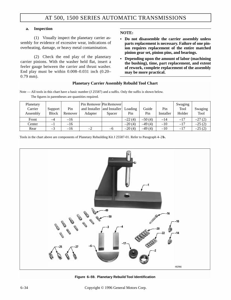
AT 500, 1500 SERIES AUTOMATIC TRANSMISSIONS
a. Inspection
(1) Visually inspect the planetary carrier as-sembly for evidence of excessive wear, indications ofoverheating, damage, or heavy metal contamination.
(2) Check the end play of the planetarycarrier pinions. With the washer held flat, insert afeeler gauge between the carrier and thrust washer.End play must be within 0.008–0.031 inch (0.20–0.79 mm).
NOTE:
• Do not disassemble the carrier assembly unlessparts replacement is necessary. Failure of one pin-ion requires replacement of the entire matchedpinion gear set, pinion pins, and bearings.
• Depending upon the amount of labor (machiningthe bushing), time, part replacement, and extentof rework, complete replacement of the assemblymay be more practical.
Planetary Carrier Assembly Rebuild Tool Chart
Note — All tools in this chart have a basic number (J 25587) and a suffix. Only the suffix is shown below.
The figures in parentheses are quantities required.
Tools in the chart above are components of Planetary Rebuilding Kit J 25587-01. Refer to Paragraph 4–2b.
Figure 6–59. Planetary Rebuild Tool Identification
PlanetaryCarrier
AssemblySupport Block
Pin Remover
Pin Remover and Installer
Adapter
Pin Remover and Installer
SpacerLoading
PinGuide
PinPin
Installer
Swaging Tool
HolderSwaging
Tool
Front –4 –16 –22 (4) –50 (4) –14 –17 –27 (2)Center –1 –16 –20 (4) –49 (4) –10 –17 –25 (2)Rear –3 –16 –2 –6 –20 (4) –49 (4) –10 –17 –25 (2)
H02966
–4
–2
–22
–10
–1
–14
–3
–25 –27 –6–17
–50
–20
–16–49
6–34 Copyright © 1996 General Motors Corp.

REBUILD OF SUBASSEMBLIES
b. Removal of Pinion Components
(1) Using a drill that is slightly smaller thanthe pinion pin diameter, drill into the swaged end onthe pins (only one end required). Do not drill into thecarrier. The rear ends of all pinion pins except those inthe center carrier assembly will be drilled. Drill thefront ends of the center assembly pins.
(2) Place press fixture J 25587-1 in a hy-draulic press. Select the proper spacer and adapter, ifrequired, from the tool chart and Figure 6–59. Positionthese parts (if used) to support the carrier assembly(drilled ends of pinion pins upward) solidly on thepress fixture.
(3) Install pin remover J 25587-16 into theram of the press fixture. Press the pinion pins from thecarrier assembly.
(4) Remove the pinion groups, consisting ofpinions, bearings, and thrust washers.
c. Replacing Bushing inFront Planetary Carrier
(1) Fabricate four dummy pins to the dimen-sions shown in Figure 6–60.
(2) Place the front carrier on a work table,rear downward.
(3) Press the bushing from the carrier. Donot scratch or score the bushing bore. (Refer to Para-graph 4–5f(1).)
(4) Place the carrier in a press, rear down-ward.
(5) Apply Loctite® Sleeve Retainer No. 601(or equivalent) to the OD of the new bushing. Installthe bushing using tool J 28501. Press the bushingflush to 0.010 inch (0.25 mm) below its adjacent sur-face (Figure 6–60). Remove excess Loctite® from thecarrier.
Figure 6–60. Front Carrier Assembly Bushing Installation
�����
Bushing to be flush to 0.010 in.(0.25 mm) below this surface
Bushing installation load must be525 LB (2335 N) in direction shown
BUSHING
DUMMY PINS (6)
SURFACE A
SURFACE B
DIA A
Diameter A must be perpendicular with surface B within 0.001 in. (0.02 mm) TIR.
With respect to surface B and the true position of the six (6) dummy pins,diameter A shall be within the total runout specified by C.
Adjust chuck jaws to achieve“0” TIR (this locates trueposition of dummy pins)
C 0.002 in. (0.05 mm) TIR
2.50 in. (63.5 mm)
2.45 in. (62.2 mm)
0.025 in. (0.63 mm)
0.5117 in. (12.997 mm)0.5114 in. (12.510 mm)
1.7534 in. (44.536 mm)1.7524 in. (44.510 mm)
DUMMY PIN
30°
V02273.01
Copyright © 1996 General Motors Corp. 6–35

AT 500, 1500 SERIES AUTOMATIC TRANSMISSIONS
(6) Using a lathe with a four jaw chuck,mount the carrier with Surface A facing the chuck. In-sert the four fabricated dummy pins (Figure 6–60) intothe pinion pin holes. Adjust the chuck, centering thecarrier based on Surface B and the runout of thedummy pins.
(7) Total runout of bushing after boring mustnot exceed 0.010 inch (0.25 mm). Use Figure 6–60 asa guide.
d. Installation of Pinion Components
NOTE:
Lubricate needle rollers and thrust washers beforeassembling the pinion groups.
(1) Assemble all the pinion groups for thecarrier assembly. Each group is assembled by insertingthe proper loading pin into the bore of the pinion, in-stalling the needle roller bearings around the loadingpin, installing a steel thrust washer at each end of thepinion, and installing a bronze thrust washer onto eachsteel thrust washer.
(2) Position the carrier assembly, rear up-ward (center carrier, front upward). Install all the pin-ion groups into the planetary carrier, aligning theloading pins with the pin bores in the carrier.
(3) Install the proper pinion guide pins (ToolChart and Figure 6–59), larger diameters first, into thepinion pin bores. Push the guide pins through the car-rier until the loading pins drop out.
(4) Position the carrier assembly on the pressfixture, using pin remover and installer adapterJ 25587-2 (if required).
(5) Select the proper pin installer, and installit into the press fixture ram.
NOTE:
Pin installers are shaped to avoid interference withbosses on the carrier assemblies. They must be in-stalled in the ram so that the cutaway portion of theinstaller will clear the bosses when the pinion pin ispressed in.
(6) Place a pinion pin onto the pilot end ofthe pin guide located below the press fixture ram.Press the pinion pin into the carrier until the installercontacts the carrier.
(7) Install the remaining pinion pins as in-structed in Step (6).
(8) Remove the carrier assembly from thepress fixture. Install swaging tool holder J 25587-17into the opening of the press fixture bed. Install aswaging tool into the holder. Install another swagingtool into the press fixture ram. Lubricate both ends ofthe pinion pins with oil-soluble grease.
(9) Position the carrier assembly, rear up-ward (center carrier, front upward) on the press fixture.Use the proper support block to level the carrier whilethe lower swaging tool is supporting the lower end ofone pinion pin.
(10) Apply sufficient pressure to the press fix-ture ram to firmly swage the ends of the pinion pinagainst the metal of the carrier. Figure 6–61 illustratesa typical swage pattern.
Figure 6–61. Typical Swaging Pattern on Pinion Pin
CAUTION:
Do not put pressure on the carrier. Distortion ofthe carrier will damage it.
Swage both ends of sixpins securely, as shown.Gears must turn freely.
90°
0.120 in. (3.048 mm) TYP
V02967
6–36 Copyright © 1996 General Motors Corp.

REBUILD OF SUBASSEMBLIES
NOTE:
Swaging pressure varies with the size of the pinionpins (approximately two tons for front carriers;three tons for center and rear carriers). While ap-plying pressure, rotate the pinions and feel for re-duction of end play. The pinions must rotate freelyand have 0.008–0.031 inch (0.20–0.79 mm) end playafter swaging the pins.
(11) Swage the remaining pinion pin ends asinstructed in Step (10).
6–17. CLUTCH STACK MEASUREMENT
a. Assembly Line
(1) When mass production overhaul prac-tices are used, the stack measurement procedure maybe more convenient.
(2) The stack dimension method is the onlymethod available for determining running clearance for:
• Forward clutch assemblies using a waveplate (models with an identification groovein the clutch housing)
• Second clutch (all models)
(3) To obtain accurate dimensions, the stackto be measured must have new clutch plates, and theapplied load must be evenly distributed.
b. Forward Clutch
(1) Stack the forward clutch plates andfourth clutch hub as shown in Figure 6–62 or 6–63.
(2) Apply the specified load, and measureDimension X.
(3) From the applicable table in Figure 6–62or 6–63, select the forward clutch piston. Use the partsmeasured, and the selected piston, in the forwardclutch assembly (Paragraph 6–10a).
c. Fourth Clutch
(1) Stack the fourth clutch plates and back-plate as shown in Figure 6–64.
Figure 6–62. Determining Forward Clutch PistonThickness (Models Not Using a Wave Plate)
Figure 6–63. Determining Forward Clutch PistonThickness (Models Using a Wave Plate)
X
PRESS 980–1020 LBS(4359–4537 N)
PLATE
SLEEVE
FOURTH-CLUTCHDRIVE HUB
INTERNAL-SPLINEDCLUTCH PLATE (5)
EXTERNAL-TANGEDCLUTCH PLATE (5)
BENCH
V02968
DIMENSION X USE PISTON
C
B
A
0.9825–1.0065 in.(24.956–25.565 mm)
1.0065–1.0325 in.(25.565–26.226 mm)
1.0325–1.0585 in.(26.226–26.886 mm)
X
PRESS 980–1020 LBS(4359–4537 N)
PLATE
SLEEVE
FOURTH-CLUTCHDRIVE HUB
INTERNAL-SPLINEDCLUTCH PLATE (5)
EXTERNAL-TANGEDCLUTCH PLATE (5)
BENCH
V02969
DIMENSION X USE PISTON
EF
E
DE
0.984–1.010 in.(24.99–25.65 mm)
1.010–1.046 in.(25.65–26.57 mm)
1.046–1.072 in.(26.57–27.23 mm)
Copyright © 1996 General Motors Corp. 6–37

AT 500, 1500 SERIES AUTOMATIC TRANSMISSIONS
(2) Apply the specified load, and measureDimension X.
(3) From the table in Figure 6–64, select thefourth clutch piston. Use the parts measured, and theselected piston, in the fourth clutch assembly (Para-graph 6–12c).
d. Third Clutch. Refer to Paragraph 7–7a forclutch clearance.
e. Second Clutch
(1) Stack the second clutch plates and pistonas shown in Figure 6–66.
(2) Apply the specified load, and measureDimension X.
NOTE:
Replace used plates, within specifications, as neededwith new to produce Dimension X. Second clutchdoes not have selective backplates.
Figure 6–64. Determining Fourth ClutchPiston Thickness
Figure 6–65. Fourth Clutch Housing Identification
Figure 6–66. Checking Second Clutch PlateRunning Clearance
Figure 6–67. Determining First ClutchBackplate Thickness
���������������������
PRESS 980–1020 LBS(4359–4537 N)
STEEL PLATE
WITH LATERCLUTCH HOUSING
(WITH IDENTIFICATIONGROOVE IN HOUSING)
(REF. FIGURE 6–65)USE PISTON
WITH EARLIERCLUTCH HOUSING
(WITHOUT IDENTIFICATIONGROOVE IN HOUSING)
(REF. FIGURE 6–65)USE PISTON
DIMENSION X
EF
E
DE
C
B
A
0.9825–1.0065 in.(24.956–25.565 mm)
1.0065–1.0325 in.(25.565–26.226 mm)
1.0325–1.0585 in.(26.226–26.886 mm)
X
FOURTH CLUTCHBACKPLATE
EXTERNAL-TANGEDCLUTCHPLATE
INTERNAL-SPLINEDCLUTCH PLATE
BENCH
V02970
GROOVE
V01306
LATER HOUSINGEARLIER HOUSING
1.919 in.(48.74 mm)
1.909 in.(48.49 mm)
1.870 in.(47.49 mm)
1.860 in.(47.25 mm)
NOGROOVE
V02971
X 1.9325–1.9685 in.(49.085–50.000 mm)
SECOND-CLUTCHPISTON STEEL PLATE
PRESS 980–1020 LBS(4359–4537 N)
STEEL PLATE
SECOND-CLUTCHBACKPLATE
INTERNAL-SPLINEDPLATES (3)
EXTERNAL-TANGEDPLATES (3)
��X
DIMENSION X
2.2875–2.3235 in.(58.103–59.016 mm)
2.3236–2.3595 in.(59.017–59.931 mm)
2.3596–2.3955 in.(59.932–60.846 mm)
LATER MODELSUSE BACKPLATE
4
5 (or no mark)
6
EARLIER MODELSUSE BACKPLATE
1
2
3
PRESS 980–1020 LBS(4359–4537 N)
STEEL PLATE
FIRST ANDREVERSECLUTCHPISTON
EXTERNAL-TANGEDCLUTCHPLATE (7)
INTERNAL-SPLINEDCLUTCH PLATE (7)
PLATE
BENCH
V02972
6–38 Copyright © 1996 General Motors Corp.

REBUILD OF SUBASSEMBLIES
(3) The clutch running clearance will bewithin limits when the stack thickness measurement isfrom 1.93–1.97 inch (49–50 mm).
(4) Use the parts measured when the trans-mission is assembled (Paragraph 7–5a).
f. First Clutch
(1) Stack the first clutch plates and piston asshown in Figure 6–67.
(2) Apply the specified load, and measureDimension X.
(3) From the table in Figure 6–67, select thefirst clutch backplate. Use the parts measured, and theselected backplate, when the transmission is assem-bled (Paragraph 7–4a).
Copyright © 1996 General Motors Corp. 6–39

6–40 Copyright © 1996 General Motors Corp.6–40 Copyright © 1996 General Motors Corp.
NOTES
AT 500, 1500 SERIES AUTOMATIC TRANSMISSIONS

Section 7 – ASSEMBLY OF TRANSMISSION
7–1. SCOPE
This section covers assembly of transmission fromsubassemblies and parts. Procedures that differ in thevarious models, or procedures that apply to only onemodel, are identified. Procedures common to all mod-els have no model identification.
7–2. GENERAL INFORMATION FOR FINAL ASSEMBLY
Refer to Sections 4 and 8 for assembly information asfollows:
7–3. SELECTIVE COMPONENTS
a. Establish Clearances
(1) Certain components are available ingraduated lengths or thicknesses to provide the properrunning clearances. These components are selected bytaking measurements at certain stages in the assemblyof the transmission.
(2) The components which are selected dur-ing assembly of the transmission are tabulated below.Refer to Parts Catalog SA1235 or SA2126 for specificpart numbers.
b. Clutch Plate Stack Measurements
(1) First clutch clearance can be determinedby direct measurement (Paragraph 7–4) or by stack di-mension measurement (Paragraph 6–7f). Refer toParagraph 6–17e for stack dimension measurement toestablish clutch clearance for second clutch. The clear-ance for third clutch is established by direct measure-ment in this section (Paragraph 7–7).
(2) An initial clutch plate running clearancecheck may be in excess of the required dimension. Donot install a thicker backplate if excess clearance canbe eliminated by installing new clutch plates.
7–4. INSTALLATION OF FIRST CLUTCH AND GEARING
a. First Clutch (Foldout 10,B)
(1) Place the transmission housing assemblyinto the holding fixture, converter housing upward.
(2) Place inner seal protector tool J 24216-01over the hub in the transmission housing (Figure 7–1).
(3) Install the inner and outer lip-type seal-rings into the grooves in the first clutch piston. Acolor-coded, outer lip-type sealring (blue) is used onthe piston after S/N 3210201937. The lips of both seal-rings must face toward the rear of the transmissionwhen the piston is installed. (Refer to sealring cross-sections on Foldout 10,B.) Lightly lubricate the sur-face of the piston bore and protector J 24216-01 withtransmission fluid before installation.
(4) Install the piston and sealrings into thetransmission housing rear bore, engaging the pistontang into the slot in the housing (Figure 7–1). Be surethe lip of the sealring on the outside diameter of thepiston is not distorted. Remove the protector tool.
Figure 7–1. Installing First Clutch Piston
Paragraph Description
4–2 Tools and Equipment4–3 Replacement Parts4–4 Careful Handling4–6 Assembly Procedures
4–10 Torque Specifications8–1 Wear Limits Data8–2 Spring Data
Component Item IllustrationThrust washer 37 (Foldout 7,B)Snapring 5 (Foldout 9,B)First clutch backplate 2 (Foldout 10,B)Spacer 3 (Foldout 12,B)
H02973
PISTONJ 24216-01
Copyright © 1996 General Motors Corp. 7–1

AT 500, 1500 SERIES AUTOMATIC TRANSMISSIONS
(5) Install twenty-two springs into the re-cesses in the piston. Install the spring retainer onto thesprings (Figure 7–2).
(6) Lay the spring retainer snapring on thespring retainer (Figure 7–2).
(7) Install spring compressor assemblyJ 23630-02 into the rear bearing bore of the transmis-sion housing (Figure 7–2). Check the springs forproper alignment.
(8) Tighten the wing-nut on the spring com-pressor until the spring retainer clears the snapringgroove in the housing hub. Install the snapring into itsgroove. Remove the spring compressor.
NOTE:
For models before S/N 5071, proceed with Step (9).For models after S/N 5070, skip Steps (9) and (10)and proceed with Step (11).
Figure 7–2. Installing First ClutchSpring Retainer Snapring
(9) For models before S/N 5071, install allfourteen first clutch plates into the transmission as fol-lows. Beginning with an external-tanged plate, alter-nately install seven external-tanged plates 4 (Foldout10,B) and seven internal-splined clutch plates 3.
(10) Install the clutch backplate (wide surfacedown) and secure it with a snapring. The first clutchsnapring must be installed with the snapring gap at the12 o'clock position (at the top of the transmissionhousing) and must be fully seated in its groove. Pro-ceed to Paragraph 7–4b and continue rebuild.
(11) After S/N 5070, place ring gear 5 (Fold-out 10,B) on a work table, extended teeth downward.Beginning with an internal-splined plate, alternatelyinstall six internal-splined and six external-tangedclutch plates onto the rear ring gear (Figure 7–3).
NOTE:
Assemble ring gear 5 (Foldout 10,B) with extendedteeth upward in housing.
(12) Pick up the ring gear and assembled firstclutch plates. Invert the assembly. Align the tangs ofthe external clutch plates on the ring gear and installthe gear and plates into the transmission as a package.Be sure the extended teeth on the ring gear are at thetop of the gear after installation.
(13) Install the two remaining clutch plates,external-tanged plate first. Install the clutch backplate(Figure 7–4) (wide surface down) and secure it with asnapring (Figure 7–5). The first clutch backplatesnapring must be installed with the snapring gap at the12 o'clock position (at the top of the transmissionhousing) and must be fully seated in its groove.
b. First Clutch Running Clearance(Foldout 10,B)
(1) Using clutch clearance gauge J 23715,check the clearance between the snapring and the back-plate (Figure 7–5). The smaller end of the gauge shouldgo into the clearance while the larger end should not.The running clearance is satisfactory when the dimen-sion is 0.040–0.100 inch (1.02–2.54 mm).
CAUTION:
When installing the first clutch snapring, do notallow the spring retainer to catch in the snapringgroove.
H02910
SNAPRING
RETAINER
J 23630-02
J 23630-3
PISTON
7–2 Copyright © 1996 General Motors Corp.

ASSEMBLY OF TRANSMISSION
Figure 7–3. Installing First Clutch Plates Onto Rear Planetary Ring Gear
H02974
INTERNAL-SPLINEDPLATE
EXTERNAL-TANGEDPLATE
RING GEAR
INTERNAL-SPLINEDPLATE
(2) If the clearance is excessive (larger endof gauge will pass between the snapring and the back-plate), new plates may be installed to reduce the clear-ance. If the clearance is still excessive after newinternal-splined and external-tanged clutch plates areinstalled, a thicker backplate is required.
(3) If the clearance is insufficient (small endof gauge will not enter), a thinner backplate is re-quired.
Figure 7–4. Installing First Clutch Backplate
(4) Backplates are stamped with identifyingnumbers (1, 2, 3, 4, 5 (or no mark), or 6). Thicknessesare as follows:
Figure 7–5. Checking First ClutchRunning Clearance
H02975
BACKPLATE
RING GEAR
Identification 1, 4 0.683 to 0.693 inch(17.35 to 17.60 mm)
2, 5, or No Stamp 0.647 to 0.657 inchIdentification (16.43 to 16.69 mm)
Identification 3, 6 0.611 to 0.621 inch(15.52 to 15.77 mm)
H02976
J 23715
RINGGEAR
BACKPLATE
SNAPRING
Copyright © 1996 General Motors Corp. 7–3

AT 500, 1500 SERIES AUTOMATIC TRANSMISSIONS
c. Planetary Gear Unit
NOTE:• Models before S/N 5071 include the rear plane-
tary ring gear as part of the planetary gear unit.Proceed with Steps (1) and (2).
• For models after S/N 5070, skip Steps (1) and (2)and proceed with Steps (3) and (4).
(1) Align the internal splines on the firstclutch pack, just installed in the main housing. Applyair pressure to first clutch feed (refer to Figure 4–5).Grasp the gear unit (as assembled in Paragraph 6–14)by the main shaft, and install it into the transmissionhousing.
(2) Make sure all the first clutch plate inter-nal splines are engaged with rear planetary ring gear53 (Foldout 10,A). Apply air pressure to the firstclutch feed, located just below the valve body oiltracks (refer to Figure 4–5). Air pressure will lift thering gear and gear pack slightly if all the splined platesare not engaged. Proceed to Paragraph 7–5 and con-tinue rebuild.
(3) On models after S/N 5070, grasp theplanetary gear unit by the main shaft and lower theunit into the transmission (Figure 7–6). Mesh the in-ternal teeth of the previously installed rear ring gear(Paragraph 7–4a(11) through (13)) with the rear plane-tary carrier pinion teeth. Be sure the unit bottoms.
(4) Install the sun gear shaft assembly (longsplines first) and the front sun gear thrust washer (Fig-ure 7–7).
7–5. INSTALLATION OF SECOND CLUTCH AND CENTER SUPPORT
a. Second Clutch Pack (Foldout 9,B)
(1) Refer to Paragraph 6–17e for secondclutch running clearance specifications. The stack di-mension procedure is the only method available fordetermining proper second clutch running clear-ance.
(2) Install the second clutch backplate (Fig-ure 7–8). Note the location of the single tang in thesingle slot in the transmission housing.
Figure 7–6. Installing Planetary Gear Unit
Figure 7–7. Installing Sun Gear Shaft Assembly and Thrust Washer
(3) Beginning with an internal-splined plate,alternately install three internal-splined and three ex-ternal-tanged second clutch plates (Figure 7–8). Thesingle tangs of the clutch plates must align with thesingle tang of the backplate.
H02977
OUTPUT SHAFT
REAR PLANETPINION
PLANETARYGEAR UNIT
MAIN SHAFT
H02978
THRUST WASHER SUN GEARSHAFT
7–4 Copyright © 1996 General Motors Corp.

ASSEMBLY OF TRANSMISSION
Figure 7–8. Installing Second Clutch Plates
(4) Install the 0.155–0.157 inch (3.94–3.99mm) thick green snapring that retains the second clutchplates (Figure 7–9). The snapring gap must be locatedat the 12 o’clock position (at the top of the transmissionhousing), and must be fully seated in its groove.
b. Center Support and Pistons (Foldout 9,B)
(1) Place center support assembly 13 on awork table and clean the piston bores of all foreignmatter.
Figure 7–9. Second Clutch Snapring Installed
(2) Be sure the lips of the sealrings of bothpistons each face (what will be after installation) thebottom of the respective piston cavity in the center sup-port. (Refer to sealring cross-sections on Foldout 9,B.)
(3) Lubricate the sealrings of the second andthird clutch pistons. Lubricate the piston bores in thecenter support.
(4) Install the third clutch piston and its at-tached parts in the front bore of the center supports,engaging the small lug on the third clutch spring re-tainer with the slot in the center support.
(5) Install the second clutch piston and its at-tached parts in the rear bore of the center support, en-gaging the small lug on the second clutch springretainer with the slot in the center support.
(6) Attach center support lifting bracketJ 23643 to the center support and carefully lower thesupport into the transmission case. During installation,align the threaded anchor bolt hole in the support withthe hole in the bottom of the transmission housing. In-stall the plain washer and a new anchor bolt into thesupport. Tighten the bolt finger tight.
CAUTION:When installing the second clutch snapring, donot allow the snapring to drag across the ma-chined surface (surface with four holes throughit). Dragging the snapring may result in leaks be-tween the passages and/or leaks to the sump.
CAUTION:Both the second and third pistons have been pre-set in Paragraph 6–13c, (3) through (6). Do notdisturb the piston spring retainer lockrings wheninstalling the pistons into the piston bores in thecenter support.
H02979
EXTERNAL-TANGED
PLATE (3)
INTERNAL-SPLINED
PLATE (2)
INTERNAL-SPLINED
PLATE
BACKPLATE
CAUTION:
Some models use a 3⁄8-16 center support anchorbolt; some use a 7⁄16-20 bolt. Take care to installthe same size bolt as was removed.
H02980
SNAPRING
GEAR SET
CLUTCHPLATES
Copyright © 1996 General Motors Corp. 7–5

AT 500, 1500 SERIES AUTOMATIC TRANSMISSIONS
(7) Install center support compressorJ 23717-C (Figure 7–10). Use two of the 5⁄16-18 x 13⁄4inch oil pump assembly retaining bolts to retain thecompressor.
(8) Tighten the compressor bolt to 5 lb ft(7 N·m) (Figure 7–10).
(9) Using snapring gauge J 34127, measurethe snapring groove clearance (Figure 7–11). Thegauge has four lugs of different thicknesses, with eachlug thickness stamped on the tool shaft. Try all fourlugs in the groove. The thickest lug which will enterthe groove indicates the thickness of the snapring re-quired.
(10) Select a snapring from the list.
(11) Install the snapring selected in Step (10).The snapring gap must be located at the 12 o’clock po-sition (at the top of the transmission housing), andmust be fully seated in its groove.
Figure 7–10. Compressing Center Support For Snapring Measurement
(12) Remove the center support compressor.
(13) Install two new hook-type sealrings 12(Foldout 9,B) onto the hub of center support assem-bly 13.
7–6. INSTALLATION OF REAR BEARING SPACER ANDFOURTH CLUTCH
a. Selecting, Installing Rear Bearing Spacer (Foldout 12,B)
(1) Install the sun gear shaft retainer J 24352for AT 500 Series or J 39736-01 for AT 1500 Seriesonto the transmission main shaft (Figure 7–12). Besure retainer sleeve is seated on the sun gear shaftwhile tightening the thumb screw.
(2) Position the transmission, rear end up-ward. Install the governor drive gear, engaging its slotwith the pin in the output shaft (Figure 7–13).
(3) Install speedometer drive gear 2 (Foldout12,B) or speed sensor wheel 9 onto the output shaft.
Figure 7–11. Measuring For Selection ofCenter Support Snapring
GaugeLug
SnapringColor Code
SnapringThickness
0.149 inch Blue 0.148–0.150 inch(3.78 mm) (3.76–3.81 mm)0.153 inch Yellow 0.152–0.154 inch(3.88 mm) (3.86–3.91 mm)0.156 inch Green 0.155–0.157 inch(3.96 mm) (3.94–3.99 mm)0.159 inch Red 0.158–0.160 inch(4.04 mm) (4.01–4.06 mm)
H02981
CENTER SUPPORT
J 23717-C H02982
CENTER SUPPORT
J 23717-C
SNAPRINGGROOVE
J 34127
7–6 Copyright © 1996 General Motors Corp.

ASSEMBLY OF TRANSMISSION
Figure 7–12. Installing Sun Gear Shaft Retainer
Figure 7–13. Installing Governor Drive Gear
(4) Using a soft drift, tap against the speed-ometer drive gear or speed sensor wheel to seat all theinstalled components.
(5) Loosen the thumbscrew on spacer selec-tion gauge J 23632-01 and position the gauge againstthe output shaft (Figure 7–14). Push the straight mem-ber of the gauge against the rear of the speedometerdrive gear. Push the lipped member against the rearbearing front snapring. It may be necessary to extendthe slot on the gauge to obtain this measurement.When the gauge is in firm contact with these parts, andthe concave side of the straight member is firmlyagainst the output shaft, tighten the thumbscrew.
Figure 7–14. Measuring For Selection ofRear Bearing Spacer
(6) Remove the gauge, and using a depth mi-crometer, measure the distance from the end of thestraight member to the lip of the curved member. Usethis dimension to select the proper rear spacer, aslisted in the following chart. Install the spacer.
*Dimension in inches (millimeters)
(7) Using bearing installer tool J 24446, in-stall rear bearing 4 (Foldout 12,B) numbered side out,as shown in Figure 7–15. Install beveled snapring 5(Foldout 9,B), flat side down.
H02983
J 24352(J 39736-01,
AT 1500 Series)
MAIN SHAFT
J 21795-4(J 39736-02,AT 1500 Series)
H02984
OUTPUTSHAFT
GOVERNORDRIVE GEAR
Dimension* UseSpacerFrom To Marked
1.0003 1.0138 23017123 1 Groove(25.408) (25.750)
1.0138 1.0273 23017124 2 Grooves(25.750) (26.093)
1.0273 1.0408 23017125 0 or 3 Grooves(26.093) (26.436) (See SIL 20-TR-92)
1.0408 1.0543 23017126 4 Grooves(26.436) (26.779)
1.0543 1.0678 23017127 5 Grooves(26.779) (27.122)
1.0678 1.0813 23017128 6 Grooves(27.122) (27.465)
H02985
OUTPUTSHAFT
J 23632-01
Copyright © 1996 General Motors Corp. 7–7

AT 500, 1500 SERIES AUTOMATIC TRANSMISSIONS
(8) Check the end play of the transmissionoutput shaft as follows.
(9) Place the first clutch spring compressorbase J 23630-2, flange side down on the output shaft(Figure 7–16). Secure the base to the output shaft witha 1⁄2-20 x 11⁄4 inch bolt. Tighten the bolt to 15 lb ft(20 N.m).
(10) Lift the output shaft with a screwdriver(Figure 7–16) and measure the distance from the topof the flange to the rear of the transmission. Releasethe output shaft and repeat the measurement. The al-lowable clearance with the proper spacer is 0.013–0.031 inch (0.33–0.79 mm). A different size spacermust be used if this clearance is not obtained.
Figure 7–15. Installing Rear Output Shaft Bearing
Figure 7–16. Checking End Play ofOutput Shaft
(11) Install spring compressor assemblyJ 23630-2. Tighten the 1⁄2-20 x 11⁄4 inch center bolt to15 lb ft (20 N·m). Align the spring compressor basewith the two parking brake mounting holes in thetransmission housing (Figure 7–17). Install two 1⁄2-13bolts through the base and into the case. Tighten thesebolts evenly to 5–8 lb ft (7–11 N·m). This positions thegear pack and all components for an accurate selectivethrust washer measurement in Paragraph 7–8.
b. Fourth Clutch (Foldout 9,A)
(1) Reposition the transmission, front up-ward. Carefully remove sun gear shaft retainer J 24352or J 39736-01 (Figure 7–12) without moving the sungear shaft.
(2) If the sun gear shaft assembly is properlyseated, there should be approximately 1⁄8 inch (3.18 mm)distance from the end of the sun gear shaft assembly tothe shoulder on the main shaft shown in Figure 7–18.If the shaft is not properly seated, a slow rotation witha slight up and down motion may seat it. If not, re-move the shaft (noting its relative position to the mainshaft) and center the front sun gear thrust washer sothe sun gear shaft will bottom. Recheck the clearance(Figure 7–18).
Figure 7–17. Positioning Components ForFront Thrust Washer Measurements
H02986
BEARING
J 24446
H02987
OUTPUTSHAFT
DEPTHGAUGE
J 23630-2
CAUTION:
• The sun gear shaft assembly must be properlyseated to establish an accurate clearance be-tween the forward clutch housing and thefront support and bearing assembly. Refer toParagraph 7–8.
• Do not remove the sun gear shaft assembly be-fore checking the required clearance shown onFigure 7–18. If the clearance is less than 1⁄8inch (3.18 mm), proceed with Step (2). Other-wise, skip Step (2) and proceed with Step (3).
H02988
PARKINGBRAKE
MOUNTINGHOLES
J 23630-02
7–8 Copyright © 1996 General Motors Corp.

ASSEMBLY OF TRANSMISSION
Figure 7–18. Sun Gear Shaft Clearance
(3) Install the fourth clutch assembly (as re-built in Paragraph 6–12) onto the splines of the sungear shaft.
7–7. INSTALLATION OF THIRD AND FORWARD CLUTCHES
a. Third Clutch (Foldout 9,B)
NOTE:
Establishing clutch clearance for the third clutchpack by stack dimension is not necessary. The run-ning clearance for this clutch is such that it will ac-cept all internal and external plates within theirrequired wear limit. (Refer to Section 8.) However,especially for models with retarder, it is critical thatthe wear limits measurements are taken and thatthe third-clutch plates are within the wear limitslisted in Section 8. The retarder housing serves as abackplate for the third clutch pack, making thepack inaccessible for a running clearance checkwhen the third clutch pack is first installed. Thirdclutch running clearance for models with retarderis not checked until the transmission is removedfrom the overhaul stand. Refer to Paragraph 7–12b.
(1) Beginning with an external-tanged clutchplate, alternately install three (models without re-tarder) or four (models with retarder) external-tangedand three internal-splined plates (Figure 7–19). Notethe location of the three pairs of tangs and a singletang in relation to paired slots and a single slot. Theplate will have minimal rotational movement whenproperly installed.
NOTE:
• For models without retarder, proceed with Step (2).
• For models with retarder, skip Steps (2) through(5) and proceed with Paragraph 7–7b.
(2) Install the third clutch backplate, align-ing its tangs with those of the three clutch plates(Figure 7–20). For models prior to S/N 3210668026,this plate is identified by the Mark 4. For later mod-els, there is a square stamped on a single externaltang.
(3) Install the snapring that retains the back-plate (Figure 7–20). The snapring is identified by agreen mark and is 0.155–0.157 inch (3.94–3.99 mm)thick. The snapring gap must be at the 12 o'clock posi-tion (viewed from the front of the transmission hous-ing), and must be fully seated in its groove.
(4) Using third clutch clearance gaugeJ 23716 (Figure 7–20), check the clutch running clear-ance. The thin end of the gauge should pass betweenthe snapring and the backplate; the thick end shouldnot. The running clearance is correct with a dimensionof 0.028–0.119 inch (0.74–3.02 mm).
(5) If clearance is excessive (larger end ofgauge enters plates), new clutch plates should replaceworn plates. Refer to the wear limits in Section 8 forclutch plate dimensions.
(6) Skip Paragraph 7–7b and proceed withParagraph 7–7c.
b. Retarder Housing Assembly. Install the re-tarder housing assembly, stator blades upward, align-ing the oil jumper tube holes with the PTO opening inthe transmission housing (Figure 7–21).
V02989
APPROX.1⁄8 in. (3.18 mm)
Copyright © 1996 General Motors Corp. 7–9

AT 500, 1500 SERIES AUTOMATIC TRANSMISSIONS
Figure 7–19. Installing Third Clutch Plates
Figure 7–20. Checking Third Clutch Running Clearance (Models Without Retarder)
Figure 7–21. Installing Retarder Housing Assembly (Models With Retarder)
c. Forward Clutch and Turbine ShaftAssembly (Foldout 8)
(1) Install the thrust washer onto the hub ofthe forward clutch assembly, retaining it with oil-solu-ble grease (Figure 7–22).
(2) Install forward clutch and turbine shaftassembly. The hub splines engage the transmissionmain shaft. The splines on the fourth clutch drive hubengage the internal splined plates of the fourth clutch.
(3) Rotate the forward clutch assembly oneor two revolutions, while pushing it downward. Makesure all the fourth clutch internal-splined plates are en-gaged.
NOTE:
• For models with retarder, proceed with Step (4).
• For models without retarder, skip Step (4) andproceed with Paragraph 7–8.
(4) For models with retarder, install twoM6-1 x 80 mm guide bolts into the retarder housingassembly (Figure 7–23). Install the front stator, statorblades first, aligning the holes in the stator with theholes in the retarder housing assembly (Figure 7–24).
Figure 7–22. Installing Thrust Washer at Rearof Forward Clutch Hub
H02990
FOURTH CLUTCHINTERNAL-SPLINED PLATE (3)
EXTERNAL-TANGED PLATE (3) – MODELS WITHOUT RETARDER(4) – MODELS WITH RETARDER
H02991
SNAPRING
J 23716
H03018
RETARDERHOUSINGASSEMBLY
H02992THRUST WASHER
FOURTHCLUTCH
DRIVE HUB
FORWARD CLUTCH ASSEMBLY
PTO DRIVEGEAR
7–10 Copyright © 1996 General Motors Corp.

ASSEMBLY OF TRANSMISSION
7–8. INSTALLATION OFOIL PUMP ASSEMBLY
a. Selection of Front Thrust Washer(Foldout 7,B)
(1) Lay thrust washer selection gauge barJ 23633 in the transmission housing (Figure 7–25).Place the depth micrometer so that its stem passesthrough the center hole in the gauge bar.
(2) Align the gauge bar so that the microme-ter stem is above the thrust washer surface of the for-ward clutch housing (Figure 7–25).
Figure 7–23. Installing Retarder Housing Assembly Guide Pins (Models With Retarder)
Figure 7–24. Installing Retarder Front Stator(Models With Retarder)
(3) Measure the distance from the top of thegauge bar to the thrust surface of the clutch housing(Figure 7–25). Subtract 1.00 inch (25.4 mm) or thethickness of the gauge bar and record the difference.Select the proper thrust washer from the following ta-ble.
*Dimension in inches (millimeters)
Figure 7–25. Measuring For Selectionof Front Thrust Washer
H03019
GUIDE BOLTS (2)M 6-1 x 80 mm
RETARDERHOUSING
ASSEMBLY
H03020
GUIDE BOLT5⁄16-18 x 3 in.
GUIDE BOLT5⁄16-18 x 3 in.
GASKET
GUIDE BOLT (2)M 6-1 x 80 mm
RETARDERFRONT
STATOR
Dimension* Thrust WasherNumberFrom To Marked
0.732 0.749 6831620 0(18.61) (19.03) Black
0.749 0.765 6831621 1(19.03) (19.44) Red
0.765 0.782 6831622 2(19.44) (19.86) Blue
0.782 0.798 6831623 3(19.86) (20.27) Green
0.798 0.814 6831624 4(20.27) (20.69) Black
0.814 0.831 6831625 5(20.69) (21.11) Black
H02993
DEPTH MICROMETERFORWARD CLUTCH
ASSEMBLYJ 23633
J 23630-2BOLT (2), 1⁄2-13
Copyright © 1996 General Motors Corp. 7–11

AT 500, 1500 SERIES AUTOMATIC TRANSMISSIONS
b. Pump Assembly (Foldout 7,B)
(1) Using oil-soluble grease, install the thrustwasher selected in Paragraph 7–8a(3), onto the oilpump assembly (Figure 7–26). The tab on the washermust engage the cast recess in the front support.
(2) Install two hook-type sealrings onto thehub of the front support (Figure 7–26).
(3) Lubricate the sealrings and thrust washerwith oil-soluble grease.
(4) Install the front support gasket, aligningthe bolt holes in the gasket with those in the transmis-sion housing (Figure 7–24 or 7–27).
Figure 7–26. Installing Hook-TypeSealrings Onto Oil Pump Assembly
Figure 7–27. Installing Front Support Gasket(Models Without Retarder)
(5) Install two 5⁄16-18 headless guide boltsinto two opposite holes in the gasket and transmissionhousing (Figure 7–24 or 7–28).
(6) Grasp the oil pump assembly by the sta-tor shaft and lower it into the transmission housing(Figure 7–28 or 7–29). Be sure the support bottoms.Remove the guide bolts.
(7) Install nine 5⁄16-18 x 13⁄4 inch self-lock-ing bolts, with nine new rubber coated washers, intothe front support and transmission housing. Tightenthe bolts to 13–16 lb ft (17–22 N.m).
Figure 7–28. Installing Oil Pump Assembly(Models Without Retarder)
Figure 7–29. Installing Oil Pump Assembly(Models With Retarder)
H02994
TAB
PUMPASSEMBLY
HOOK-TYPESEALRING (2)
THRUSTWASHER
H02995
TURBINE SHAFT
GASKETFORWARDCLUTCH
H02996
GUIDE PINS
OIL PUMPASSEMBLY
H03021
GUIDE BOLTS GUIDE BOLTS
OIL PUMPASSEMBLY
7–12 Copyright © 1996 General Motors Corp.

ASSEMBLY OF TRANSMISSION
NOTE:
• For models with retarder, proceed with Step (8).
• For models without retarder, skip Step (8) andproceed with Step (9).
(8) For models with retarder, install six M6-1bolts 39 (Foldout 7,B). Tighten bolts 39 to 9–10 lb ft(12–14 N.m).
(9) To check the turbine shaft end play,mount a vernier dial caliper on the turbine shaft. Raisethe shaft, extending the depth gauge to bear upon thestator shaft and record the dial reading (Figure 7–30).
(10) Release the shaft and record the dial read-ing. If the dial reading does not fall within the desiredend play range of 0.005–0.034 inch (0.13–0.85 mm),the thickness of the selective thrust washer must be re-calculated.
(11) Remove the compressor base, J 23630-2,installed in Paragraph 7–6a, from the transmissionhousing and output shaft.
7–9. INSTALLATION OF OUTPUT SHAFT OIL SEAL (Foldout 12,B)
(1) Refer to Paragraph 4–6e. Coat the lip ofoil seal 6 with high temperature grease.
Figure 7–30. Measuring Turbine Shaft End Play
(2) Start the oil seal, lip first, squarely intothe rear bore of the transmission housing.
(3) Using installer tool J 23631, drive the oilseal into the housing until the installer seats against thehousing (Figure 7–31). The rear of the oil seal will be0.51–0.55 inch (13.0–14.0 mm) forward of the brakemounting surface of the transmission housing whenproperly installed.
(4) Refer to Paragraph 3–16h for the instal-lation of the output flange and retaining bolt andwasher.
7–10. INSTALLATION OF MAIN CONTROL VALVE BODY, OIL FILTER, AND OIL PAN
a. Main Control Valve Body
NOTE:
If the control valve body assembly was replaced, itwill perform properly only if it is functionally com-patible with the main housing channeling. Refer toParts Catalog SA1235 for part numbers and serialnumber application.
(1) Position the transmission housing bottomside upward.
Figure 7–31. Installing Output Shaft Oil Seal
H02997
STATORSHAFT
DEPTHGAUGETURBINE SHAFT
H02998
J 23631
Copyright © 1996 General Motors Corp. 7–13

AT 500, 1500 SERIES AUTOMATIC TRANSMISSIONS
(2) If the anchor bolt is 3⁄8-16, tighten it to39–46 lb ft (53–62 N.m); if the anchor bolt is 7⁄16-20,tighten it to 67–80 lb ft (91–108 N.m) (Figure 7–32).
(3) For earlier models, install the governorcheck valve ball into the channel in the transmissionhousing (Figure 7–32).
NOTE:If it is necessary to install the main control valve as-sembly from under a vehicle, apply oil-solublegrease to the governor check valve ball to locate iton the separator plate of the assembled controlvalve body.
(4) Position the main control valve body onthe transmission housing in its approximate installedposition (Figure 7–33)
Figure 7–32. Installing Governor Check Ball(Earlier Models)
(5) Install governor circuit screen 12 (Fold-out 12,B) closed end first, into the valve body, at thegovernor feed tube opening (Figure 7–33). Install thegovernor feed tube.
NOTE:
Inspect both ends of the governor feed tube. Earliermodels contained a plastic screen located where thegovernor feed tube unites with the housing. Thisscreen must be replaced with a wire screen and relo-cated in the governor feed tube bore (Figure 7–33).
(6) Install the governor pressure tube (Figure7–33).
(7) For earlier models, install the short, non-braced, first clutch feed tube.
(8) Lift the main control valve body andswing the three tubes into proper position to enter theirholes in the transmission case.
(9) Lower the main control valve body ontothe case, while engaging the rear ends of the tubes inthe case, and the selector valve on the selector lever(Figure 7–33). Remove valve body lifter tool J 29863.
(10) For later models, install the long-bracedfirst clutch feed tube (Figure 7–33).
(11) Install the detent spring, with its rollerover the selector lever, and its rear tab in the hole im-mediately behind the bolt hole (Figure 7–33).
(12) Install a 1⁄4-20 x 13⁄4 inch bolt into the de-tent spring and valve body.
(13) For later models, install sixteen valvebody retaining bolts. Earlier models use one 1⁄4-20 x 23⁄4inch bolt and seventeen 1⁄4-20 x 21⁄4 inch bolts or eigh-teen 1⁄4-20 x 21⁄4 inch bolts (Figure 7–33).
(14) On models equipped with a deep oil pan,install filter spacer 41 or 49 (Foldout 12,B). Use 1⁄4-20x 3 inch valve body retaining bolts to retain the spacer.
(15) Shake the valve body slightly, and theends of the bolts will start into the tapped holes in thetransmission case.
CAUTION:
Do not allow the selector valve to fall out duringhandling of the main control valve assembly.
CAUTION:
If the governor feed and pressure tubes are in-stalled, rear end first, they will not align properlywhen the main control valve is installed. Theymay appear to align until installation of the maincontrol valve body is attempted.
H02899
ANCHOR BOLT
STEEL CHECK BALL
NONMAGNETIC ROD
7–14 Copyright © 1996 General Motors Corp.

ASSEMBLY OF TRANSMISSION
Figure 7–33. Installing Valve Body and Sump Components
BOLT – LATER MODELS (16)BOLT – EARLIER MODELS (17) OR (18)
FIRST CLUTCH FEEDTUBE BOLTS, 3 in. (2)
INTAKE TUBE
FILTER SPACER
FILTER SCREEN INGOVERNOR FEED
TUBE BOREGOVERNORFEED TUBE
GOVERNORPRESSURE TUBE
DETENT SPRINGBOLT, 13⁄4 in.
DETENT SPRING
SELECTOR LEVER
FIRST CLUTCH TUBE(EARLIER MODELS)
H02898
NOTE:
The detent spring must be held in alignment overthe selector lever while the 13⁄4 inch bolt is tight-ened.
(16) Using preset torque wrench J 29612,tighten the bolts evenly to 8–12 lb ft (11–16 N·m).
b. Filter
(1) Install the sealring onto the straighter endof the intake tube. Lubricate the sealring with trans-mission fluid.
CAUTION:
Avoid twisting the intake tube or filter when in-stalling the filter, intake tube, and sealring. Thesealring may become pinched, cut, or deformed.An airtight seal must be maintained.
Copyright © 1996 Ge
(2) Install the intake tube and sealring (Fig-ure 7–34).
(3) Install the filter onto the intake tube,making sure the grommet in the filter fits the intakepipe snugly (Figure 7–34).
NOTE:Turn the intake tube until it enters the grommetsquarely.
(4) Retain the filter with bolt 35 (Foldout12,B) or bolt 42 and washer 43 for the deep pan or bolt23 for the shallow pan configuration. Tighten the boltto 10–15 lb ft (14–20 N·m).
c. Oil Pan
(1) Position the pan gasket on the transmis-sion housing, aligning its bolt holes with those in thehousing (Figure 7–35).
neral Motors Corp. 7–15

AT 500, 1500 SERIES AUTOMATIC TRANSMISSIONS
(2) Position the oil pan on the transmissionhousing.
(3) Refer to Paragraph 3–10b for oil pan in-stallation and torque requirements.
Figure 7–34. Installing Oil Filter Screw and Washer(Models Prior to S/N 3210622842)
Figure 7–35. Installing Transmission Oil Pan(Shallow Pan Models)
7–11. INSTALLATION OF GOVERNOR, MODULATOR, AND TORQUE CONVERTER
a. Governor
(1) Install the governor cover gasket onto thetransmission housing, using oil-soluble grease to re-tain it (Figure 7–36).
(2) Install the governor assembly by pushingit inward with a slight rotation (Figure 7–36).
(3) Install the governor cover and retain itwith four 5⁄16-18 x 9⁄16 inch bolts (Figure 7–37).Tighten the bolts to 15–20 lb ft (20–27 N·m).
b. Vacuum Modulator
(1) For earlier models, install the vacuummodulator valve actuating rod, larger diameter endfirst (Figure 7–37). On diesel units (before S/N 22700)where a mechanical actuator is used, actuator pin 28(Foldout 12,A) is one diameter. After S/N 22699, rod28 (with two diameters) is used.
Figure 7–36. Installing Governor Assembly
H02999
INTAKE TUBE
SCREW
H03000
GASKET
OIL FILTER
OIL PAN
SCREW
H02896
OIL PAN
SCREW(21)
GOVERNORASSEMBLY
GASKET
7–16 Copyright © 1996 General Motors Corp.

ASSEMBLY OF TRANSMISSION
(2) Install the sealring onto the vacuummodulator (Figure 7–37). Lubricate the sealring withoil-soluble grease. Install the vacuum modulator.
(3) Rotate the vacuum modulator until thehose nipple faces ten degrees downward (toward bottomof transmission) and directly forward (Figure 7–38).
(4) Install the modulator retainer, bent tabstoward transmission, and secure it with a 5⁄16-18 x 3⁄4inch bolt (Figure 7–38). Tighten the bolt to 10–16 lb ft(14–22 N·m).
Figure 7–37. Installing Vacuum Modulator
Figure 7–38. Installing Vacuum ModulatorRetainer Bolt
c. Torque Converter Assembly(Foldout 7,A or B)
(1) Position the transmission housing frontend upward. Install the torque converter assembly intothe transmission housing (Figure 7–39). Be sure thesplines on the converter turbine shaft engage thesplines in the converter turbine hub, and the tangs onthe converter pump hub engage the input pump drivegear. (Refer to Foldout 1, 2, or 3.)
(2) Install the torque converter retainingstrap before removing the transmission from the hold-ing fixture.
Figure 7–39. Installing TorqueConverter Assembly
H02895
VALVE ACTUATING ROD(EARLIER MODELS) SEALRING
VACUUMMODULATOR
GOVERNORCOVER
BOLT, 5⁄16-18 x 9⁄16 in. (4)
H02894
BOLT
RETAINER
VACUUMMODULATOR
CAUTION:
Allison Transmission Division GM recommendsonly genuine Allison torque converters for usewith any AT 500, 1500 Series Allison transmis-sions. Any transmission damage that may occuras a result of using a converter other than a newAllison converter or a genuine Allison replace-ment is the responsibility of the owner and willnot be covered by Allison warranty.
H02893
TORQUECONVERTERASSEMBLY
J 23642-01J 3289-20
TURBINE SHAFTSTATORSHAFT
Copyright © 1996 General Motors Corp. 7–17

AT 500, 1500 SERIES AUTOMATIC TRANSMISSIONS
7–12. REMOVAL OF TRANSMISSION FROM OVERHAUL STAND AND INSTALLATION OF EXTERNAL COMPONENTS
a. Supporting Transmission
(1) Attach a sling to the transmission. Sup-port the transmission and remove it from the holdingfixture.
(2) Remove adapter J 23642-01 (Figure 7–39).Lower the transmission to a supporting surface, and re-move the sling.
NOTE:
• For models with retarder, proceed with Para-graphs 7–12b and 7–12c.
• For models without retarder, skip Paragraphs7–12b and 7–12c, and proceed with Paragraph7–12d.
b. Determining Third Clutch Clearance
(1) Using third clutch clearance gaugeJ 23716, enter through the retarder valve body (PTOpad) opening to access the third clutch pack, andcheck the running clearance. The thin end of the gaugeshould pass between the retarder housing and the firstclutch plate; the thick end should not. The runningclearance is correct with a dimension of 0.028–0.119inch (0.74–3.02 mm).
(2) If clearance is excessive (larger end ofgauge enters plates), rebuild the transmission to thearea of the third clutch and replace worn plates withnew plates. Refer to the wear limits in Section 8 forclutch plate dimensions.
(3) When third clutch clearance is proper,proceed with Paragraph 7–12c.
c. Installing Retarder Valve Body
(1) Lay retarder control valve assembly 18(Foldout 13) on the work table, outside surface down-ward.
(2) Put one gasket 16, separator plate 17, anda second gasket 16 in place on retarder control valveassembly 18.
(3) Put transfer plate assembly 6 in place ongasket 24 and carefully install four 1⁄4-20 x 11⁄4 inchbolts 4 and flat washers 5, aligning the parts. Usingpreset torque wrench J 29612, tighten bolts 4 to 8–12lb ft (10–16 N.m).
(4) Through the retarder valve body (PTO)pad opening, install two jumper tubes 2 into theirbores in the retarder housing.
(5) Install gasket 1 and complete retarder valvebody assembly 3, retaining them with four 3⁄8-16 x 41⁄4inch bolts 36. Tighten the bolts to 26–32 lb ft (36–43 N.m).
(6) Skip Paragraph 7–12d and proceed withParagraph 7–12e.
d. Installing PTO Cover (Foldout 12,A)
NOTE:If the PTO is to be installed right away, skip Steps(1) and (2) and proceed with Paragraph 7–12e.
(1) Install gasket 1 and cover 2.
(2) Retain the cover with six 3⁄8-16 x 3⁄4 inchbolts 3. Tighten bolts 3 to 15–20 lb ft (20–27 N·m).
e. Installing Neutral Start Switch,Speedometer Components
(1) If not previously installed, install neu-tral start switch or plug with socket wrench J 33410using partial turns of the wrench. Tighten the switchto 50–60 lb ft (68–81 N·m) or, tighten the plug to24–45 lb ft (33–60 N·m). Make sure the tool is notcontacting the transmission housing when verifyingfinal torque reading.
(2) Install speedometer driven gear assem-bly or plug, as required. Tighten locking nut or plugto 45–50 lb ft (61–68 N·m).
f. Shift Lever Installation. Refer to Paragraph3–12 for installation specifications.
7–18 Copyright © 1996 General Motors Corp.

ASSEMBLY OF TRANSMISSION
7–13. CHECKING AND ADJUSTING SHIFT POINTS
Refer to Paragraph 3–13 for shift point checks and ad-justments.
7–14. POWER TAKEOFF COMPONENTS (Models Without Retarder)
a. Existing Installation
(1) Unless space limitations prevent, installthe PTO components before the transmission is in-stalled in the vehicle.
(2) Use the proper shims or gaskets to estab-lish satisfactory gear backlash 0.006–0.029 inch(0.15–0.73 mm) or as specified by the PTO manufac-turer.
b. Determining Turbine-DrivenPTO Backlash
NOTE:A PTO that whines in operation usually has too lit-tle backlash (too tight); a clatter indicates too muchbacklash (too loose).
(1) Position tool J 34814 (Figure 7–40) ontoPTO pad with plunger engagement between two drivegear teeth.
(2) Tighten the two hold-down bolts.
(3) Measure the height between the gaugepin and base plate (Figure 7–40) with a feeler gaugeand refer to the chart.
(4) Install the two headless guide bolts, oneinto the top and one into the bottom of the PTOmounting pad. Place the required shims or gasket onthe guide bolts.
(5) If the PTO has a manual disconnect, besure that the disconnect lever is in the disconnect posi-tion. When the PTO is installed on the mounting pad,the PTO driven gear must be to the rear of the PTOdrive gear in the transmission.
(6) Install the PTO on the mounting pad.
(7) Connect the lubrication line (if used).
c. New Installation
(1) Contact Allison Transmission Divisionof General Motors for approval of planned installation,or for recommendations.
(2) Speeds, type of duty, power require-ments, and other factors must be considered when add-ing a PTO to a transmission. If the job requirements ofthe PTO cannot be fully met by the transmission, theinstallation will not be satisfactory. Also, the transmis-sion could be damaged.
(3) Follow all of the recommendations inParagraph 7–14a and 7–14b.
(4) If a lubrication source is required, the re-turn line from-cooler-to-transmission may be tapped.Provide a 0.032 inch (0.81 mm) restriction in the lubri-cation circuit (usually already provided in the PTO as-sembly).
CAUTION:
Cork or other soft gasket material cannot beused to mount the PTO. Use only the shims orgaskets recommended by the PTO manufacturer.
CAUTION:
The transmission and PTO can be damaged ifthe PTO is installed with its drive gear to thefront of the PTO drive gear.
Copyright © 1996 General Motors Corp. 7–19

AT 500, 1500 SERIES AUTOMATIC TRANSMISSIONS
Figure 7–40. Measuring Turbine-Driven PTO Backlash (Models Without Retarder)
��
MEASUREMENT
0.011–0.046 inch(0.27–1.16 mm)
0.047–0.070 inch(1.19–1.78 mm)
CORRECTION
One 0.030 inch Gasket(One 0.76 mm Gasket)
Two 0.030 inch Gaskets(Two 0.76 mm Gaskets)
Correct Height
Correct Height
V02394
TRANSMISSIONMAIN CASE
BASE PLATE
GAUGE PIN
PTO PAD
HOLD-DOWNBOLT
J 34814 PTO DRIVEGEAR
MEASUREMENT
7–20 Copyright © 1996 General Motors Corp.

Section 8 – WEAR LIMITS AND SPRING DATA
8–1. WEAR LIMIT DATA
NOTE:For detailed inspection criteria, refer to SA1948,AT Technician’s Guide.
(1) Wear limit information in this sectionshows the maximum wear at which components areexpected to function satisfactorily. Table 8–1 lists thewear limits data and is referenced to the explodedviews (Foldouts 7 through 13) in the back of thismanual.
(2) Parts must be clean to permit effective in-spection for wear or damage. Refer to Paragraph 4–5.
Copyright © 1996 Ge
8–2. SPRING DATA
(1) Springs must be clean to permit effectiveinspection. Replace springs if there are signs of over-heating, wear due to rubbing adjacent parts, or perma-nent set. Discard springs which do not meet the loadheight specifications in the spring chart.
(2) Inspection criteria (load vs height) andidentification characteristics of the springs are pre-sented in Table 8–2. The spring data are keyed to theexploded views (Foldouts 7 through 13) in the back ofthis manual.
NOTE:Where more than one spring part number is listedfor the same location, refer to the Parts CatalogSA1235 or SA2126 to determine which spring isused in your specific assembly number.
Table 8–1. Wear Limits
Wear Limit
Illustration Description inch (mm)
Foldout 7,A TORQUE CONVERTER ASSEMBLY
16 Converter stator
17, 22 Max inside diameter of side plates 2.857 72.56
17, 24 Converter stator
Min thickness of front side plate plus installed bearing 0.435 11.05
25 Freewheel roller race — min outside diameter No scoring permitted.
Foldout 7,B TORQUE CONVERTER, OIL PUMP ASSEMBLIES
1, 7 Torque converter hub — max clearance in bushing 0.005 0.12
1 Torque converter assembly — max turbine end play (except AT 543) 0.037 0.93
8, 9 Pump driven gear 9
Max diametral clearance in body 8 0.0089 0.226
9, 10 Pump drive and driven gear — max side clearance 0.0026 0.066
18 Stator shaft bushing
Max clearance on turbine shaft 9 or 14 (Foldout 8) 0.004 0.10
Foldout 8 FORWARD CLUTCH AND TURBINE SHAFT
7 or 11 Turbine shaft
Max clearance in bushing 18 (Foldout 17,B) 0.004 0.10
neral Motors Corp. 8–1

AT 500, AT 1500 SERIES AUTOMATIC TRANSMISSIONS
Foldout 8 FORWARD CLUTCH AND TURBINE SHAFT (cont’d)
27, 28 External-tanged clutch plate
Min thickness No visible wear or scoring permitted.
Max cone 0.004 0.10
29 Internal-splined clutch plate — min thickness 0.071 1.80
Min depth of oil grooves 0.008 0.21
30 Fourth clutch drive hub
Min thickness at friction face No visible wear or scoring permitted.
Foldout 9,A FOURTH CLUTCH
2 Clutch backplate — min thickness No visible wear or scoring permitted.
3 Internal-splined clutch plate — min thickness 0.071 1.80
Min depth of oil grooves 0.008 0.21
4 External-tanged clutch plate
Min thickness No visible wear or scoring permitted.
Max cone 0.004 0.10
Foldout 9,B SECOND CLUTCH, THIRD CLUTCH, CENTER SUPPORT
2 Third clutch backplate — min thickness No visible wear or scoring permitted.
3, 24 Internal-splined clutch plate — min thickness 0.090 2.29
Min depth of oil grooves 0.008 0.21
4, 23 External-tanged clutch plate
Min thickness No visible wear or scoring permitted.
Max cone 0.010 0.25
14 Center support bushing
Max clearance on shaft 3 (Foldout 10,A) 0.005 0.12
25 Second-clutch backplate — min thickness No visible wear or scoring permitted.
Foldout 10,A PLANETARY GEAR UNIT
2 Sun gear shaft bushing — max clearance on shaft 4 0.0045 0.114
3 Sun gear shaft
Max clearance in bushing 14 (Foldout 9,B) 0.005 0.12
Table 8–1. Wear Limits (Cont’d)
Wear Limit
Illustration Description inch (mm)
8–2 Copyright © 1996 General Motors Corp.

WEAR LIMITS AND SPRING DATA
Foldout 10,A PLANETARY GEAR UNIT (cont’d)
4 Transmission main shaft — max clearance in bushing 2 0.0045 0.114
15 Front planetary carrier bushing
Max clearance on sun gear 19 0.005 0.12
47 Output shaft bushing — max clearance on shaft 4 0.0065 0.165
Foldout 10,B FIRST CLUTCH
2 Backplate (ident 1, 2, 3, 4, 5, 6) — min thickness No visible wear or scoring permitted.
3 Internal-splined clutch plate — min thickness 0.090 2.29
Min depth of oil grooves 0.008 0.21
4 External-tanged clutch plate
Min thickness No visible wear or scoring permitted.
Max cone 0.010 0.25
Foldout 12,A TRANSMISSION HOUSING, GOVERNOR
11 Transmission housing
Max clearance of governor bore on governor 18 0.0035 0.088
Table 8–1. Wear Limits (Cont’d)
Wear Limit
Illustration Description inch (mm)
Copyright © 1996 General Motors Corp. 8–3

8–4C
opyright © 1996 G
eneral Motors C
orp.
AT
500, AT
1500 SE
RIE
S A
UT
OM
AT
IC T
RA
NS
MIS
SIO
NS
Table 8–2. Spring Data
Spring Free
Color No. Wire dia OD Length Length Under Load
Foldout Ref Spring Part No. Code Coils in. (mm) in. (mm) in. (mm) in. (mm) lb (N)
7,A 27 Stator 6774966 No color code Convoluted Spring 0.64 0.30 0.15–0.33
(16.3) (7.6) (0.7–1.5)
7,B 26 Main pressure 6833294 Solid orange 14 0.125 1.06 4.19 2.01 74.16–78.76
regulator valve (3.18) (26.9) (106.4) (51.1) (329.9–350.3)
7,B 31 Lockup valve 29501072 Solid purple 14 0.125 1.06 4.27 2.01 77.2–81.8
(3.18) (26.9) (108.5) (51.1) (343–363)
29505835 No color 18.7 .098 0.648 3.11 2.51 25.83–31.57
(2.49) (16.46) (79.0) (63.8) (114.9–140.4)
8 20 Forward clutch 8624073 Solid red 10.5 0.055 0.45 1.31 0.88 8.50–12.22
piston release (1.40) (11.4) (33.3) (22.4) (37.8–54.4)
23045233 Solid red 10.5 0.056 0.45 1.28 0.88 10.00–12.00
(1.42) (11.4) (32.5) (22.4) (44.5–53.4)
29505884 Dark blue 9.5 .055 .0455 1.30 0.88 10.0–12.0
(1.40) (11.56) (33.0) (22.3) (44.5–53.4)
9,A 7 Fourth clutch piston release 8624073 Solid red 10.5 0.055 0.45 1.31 0.88 8.50–12.22
(1.40) (11.4) (33.3) (22.4) (37.8–54.4)
23045233 Solid red 10.5 0.056 0.45 1.28 0.88 10.00–12.00
(1.42) (11.4) (32.5) (22.4) (44.5–53.4)
29505884 Dark blue 9.5 .055 0.455 1.30 0.88 10.0–12.0
(1.40) (11.56) (33.0) (22.3) (44.5–53.4)
9,B 8 Third clutch piston release 6831656 Solid green 11.5 0.041 0.38 1.29 0.82 4.30–5.95
(1.04) (9.7) (32.8) (20.8) (19.1–26.5)
9,B 19 Second clutch piston release 6831656 Solid green 11.5 0.041 0.38 1.29 0.82 4.30–5.95
(1.04) (9.7) (32.8) (20.8) (19.1–26.5)
10,B 8 First clutch piston release 6831702 Solid yellow 11.5 0.044 0.45 1.53 1.01 3.59–4.81
(1.12) (11.4) (38.9) (25.7) (16.0–21.4)
6880251 Solid orange, 10 0.063 0.45 1.28 0.95 13.60–16.40
yellow stripe (1.60) (11.4) (32.5) (24.1) (60.5–73.0)

Copyright ©
1996 General M
otors Corp.
8–5
WE
AR
LIM
ITS
AN
D S
PR
ING
DA
TA
11 7 Modulator valve 6833934 Solid white, 10 0.054 0.49 1.47 0.80 11.90—13.10
orange stripe (1.37) (12.4) (37.3) (20.3) (52.9—58.3)
6838077 Solid yellow 10 0.054 0.49 1.15 0.80 6.01—7.15
(1.37) (12.4) (29.2) (20.3) (26.7—31.8)
6880980 Solid light 10 0.054 0.49 1.36 0.80 9.88—10.92
blue, red stripe (1.37) (12.4) (34.5) (20.3) (43.9—48.6)
23012937 Solid white 9 0.99 0.95 2.27 1.94 9.40—11.40
(2.52) (24.1) (57.7) (49.3) (41.8—50.7)
23012948 Solid white, 10 0.054 0.49 1.47 0.80 11.90—13.10
orange stripe (1.37) (12.4) (37.3) (20.3) (52.9—58.3)
11 14 Third clutch trimmer valve 6833938 Solid yellow 12.5 0.080 0.94 2.96 1.10 15.95—17.65
(2.03) (23.9) (75.2) (27.9) (70.9—78.5)
6833945 Solid light 7.4 0.092 0.93 2.27 1.94 9.40—11.40
blue (2.34) (23.6) (57.7) (49.3) (41.8—50.7)
6880045 Solid orange 10 0.099 0.94 2.18 1.94 6.20—7.40
(2.51) (23.9) (55.4) (49.3) (27.6—32.9)
23012937 Solid white 9 0.099 0.95 2.27 1.10 34.80—38.80
(2.51) (24.1) (57.7) (27.9) (154.8—172.6)
23017086 Solid white, 8.5 0.105 0.95 2.21 1.94 11.0—13.4
black stripe (2.67) (24.1) (56.1) (49.3) (48.9—59.6)
23018733 One end 11.3 0.078 0.94 2.98 1.94 8.30—10.30
orange (1.98) (23.9) (75.7) (49.3) (36.9—45.8)
11 NI* Third clutch trimmer valve 6885166 Orange, 9.6 0.092 0.69 1.69 1.10 32.60—39.80
(inner) (earlier models) white stripe (2.34) (17.53) (42.9) (27.9) (145.0—177.0)
(inner spring no longer used) 23011987 Solid red, 11 0.072 0.68 1.52 1.10 7.20—8.80
orange stripe (1.83) (17.3) (38.6) (27.9) (32.0—39.1)
Table 8–2. Spring Data (Cont’d)
Spring Free
Color No. Wire dia OD Length Length Under Load
Foldout Ref Spring Part No. Code Coils in. (mm) in. (mm) in. (mm) in. (mm) lb (N)
*NI — Not Illustrated

8–6C
opyright © 1996 G
eneral Motors C
orp.
AT
500, AT
1500 SE
RIE
S A
UT
OM
AT
IC T
RA
NS
MIS
SIO
NS
11 18 First clutch trimmer 6833945 Solid light 7.4 0.092(2.34)
0.93 2.27 1.94 9.40—11.40
valve (outer) blue (23.6) (57.7) (49.3) (41.8—50.7)
6838839 Solid purple, 8 0.092 0.93 1.95 1.10 22.4—26.4
orange stripe (2.34) (23.6) (49.5) (27.9) (99.6—117.4)
6839271 Solid white, 10 0.102 0.94 2.56 1.94 20.00—22.00
yellow stripe (2.59) (23.9) (65.0) (49.3) (89.0—97.9)
6880045 Solid orange 10 0.099 0.94 2.18 1.94 6.20—7.40
(2.51) (23.9) (55.4) (49.3) (27.6—32.9)
23012937 Solid white 9 0.099 0.95 2.27 1.10 34.80—38.80
(2.51) (24.1) (57.7) (27.9) (154.8—172.6)
11 19 Second clutch trimmer 6839102 Solid red 8.5 0.092 0.72 1.68 1.10 32.60—39.80
valve (inner) (2.34) (18.3) (42.7) (27.9) (145.0—177.0)
6880118 Blue, 8.5 0.091 0.69 1.45 1.10 21.70—25.30
white stripe (2.31) (17.53) (36.8) (27.9) (96.5—112.5)
6880274 Solid yellow, 9.6 0.092 0.69 1.69 1.10 32.60—39.80
blue stripe (2.34) (17.5) (42.9) (27.9) (145.0—177.0)
6884701 Solid orange 9.6 0.092 0.69 1.69 1.10 32.60—39.80
(2.34) (17.5) (42.9) (27.9) (145.0—177.0)
6885166 Solid orange, 9.6 0.091 0.72 1.69 1.10 32.60—39.80
white stripe (2.31) (18.3) (42.9) (27.9) (145.0—177.0)
11 23 Second clutch trimmer 6833940 Solid orange, 8.5 0.121 0.95 2.38 1.94 29.00—35.00
valve (outer) yellow stripe (3.07) (24.1) (60.5) (49.3) (129.0—155.7)
6837692 Yellow 9.5 0.101 0.94 2.33 1.20 37.80—41.88
(2.57) (23.88) (59.2) (30.5) (168.1—185.9)
6838532 Solid white 8.5 0.121 0.95 2.10 1.94 10.50—15.50
(3.07) (24.1) (53.3) (49.3) (46.7—68.9)
6839102 Solid red 8.5 0.092 0.72 1.68 1.10 32.60—39.80
(2.34) (18.3) (42.7) (27.9) (145.0—177.0)
6839271 Solid white, 10 0.102 0.94 2.56 1.94 20.00–22.00
yellow stripe (2.59) (23.9) (65.0) (49.3) (89.0–97.9)
Table 8–2. Spring Data (Cont’d)
Spring Free
Color No. Wire dia OD Length Length Under Load
Foldout Ref Spring Part No. Code Coils in. (mm) in. (mm) in. (mm) in. (mm) lb (N)

Copyright ©
1996 General M
otors Corp.
8–7
WE
AR
LIM
ITS
AN
D S
PR
ING
DA
TA
11 23 Second clutch trimmer 6883300 Solid light 10 0.082 0.69 1.95 1.10 31.20–37.20
valve (outer) (cont’d) green, white (2.08) (17.5) (49.5) (27.9) (138.8–165.5)
6885047 Solid light 10 0.098 0.94 2.57 1.94 16.10–19.70
green (2.49) (23.9) (65.3) (49.3) (71.6–87.6)
6885164 Solid white, 8.5 0.121 0.95 2.10 1.94 10.50–15.50
orange stripe (3.07) (24.1) (53.3) (49.3) (46.7–68.9)
23011988 Solid yellow, 8.5 0.092 0.94 2.31 1.10 29.0–32.2
orange stripe (2.34) (23.88) (58.7) (27.9) (129.0–143.2)
23012937 Solid white 9 0.099 0.95 2.27 1.10 34.80–38.80
(2.51) (24.1) (57.7) (27.9) (154.8–172.6)
23017086 Solid white, 8.5 0.105 0.95 2.21 1.94 11.00–13.40
black stripe (2.67) (24.1) (56.1) (49.3) (48.9–59.6)
11 24 Second clutch trimmer 6839102 Solid red 8.5 0.092 0.72 1.68 1.10 32.60–39.80
valve (inner) (2.34) (18.3) (42.7) (27.9) (145.0–177.0)
6880045 Orange 10 0.099 0.94 2.18 1.94 6.20–7.40
(2.51) (23.88) (55.4) (49.3) (27.6–32.9)
6883300 Solid lt. green, 10 0.082 0.69 1.95 1.10 31.20–37.20
white stripe (2.08) (17.5) (49.5) (27.9) (138.8–165.5)
6885166 Solid orange, 9.6 0.091 0.72 1.69 1.10 32.60–39.80
white stripe (2.31) (18.3) (42.9) (27.9) (145.0–177.0)
23013908 Solid white 10 0.080 0.69 1.80 1.10 21.50–23.70
(2.03) (17.53) (45.7) (27.9) (95.5–105.5)
11 27 Trim boost accumulator 23013744 Solid light blue, 13 0.060 0.62 2.61 0.95 15.50–17.10
valve white stripe (1.52) (15.7) (66.3) (24.1) (68.9–76.1)
23013054 Solid orange, 15 0.054 0.62 2.72 0.90 8.70–10.70
light blue stripe (1.37) (15.7) (69.1) (22.9) (38.7–47.6)
11 31 Fourth clutch trimmer 6837692 Yellow 9.5 0.101 0.94 2.33 1.20 37.80–41.80
valve (outer) (2.57) (23.88) (59.2) (30.5) (168.1–185.9)
6839271 Solid white, 10 0.102 0.94 2.56 1.94 20.00–22.00
yellow stripe (2.59) (23.9) (65.0) (49.3) (89.0–97.9)
Table 8–2. Spring Data (Cont’d)
Spring Free
Color No. Wire dia OD Length Length Under Load
Foldout Ref Spring Part No. Code Coils in. (mm) in. (mm) in. (mm) in. (mm) lb (N)

8–8C
opyright © 1996 G
eneral Motors C
orp.
AT
500, AT
1500 SE
RIE
S A
UT
OM
AT
IC T
RA
NS
MIS
SIO
NS
11 31 Fourth clutch trimmer 6880045 Orange 10 0.099 0.94 2.18 1.94 6.20–7.40
valve (outer) (cont’d) (2.51) (23.88) (55.4) (49.3) (27.6–32.9)
23012937 Solid white 9 0.099 0.95 2.27 1.94 9.40–11.40
(2.52) (24.1) (57.7) (49.3) (41.8–50.7)
11 32 Fourth clutch trimmer 6880118 Solid light blue, 8.5 0.091 0.69 1.42 1.10 20.70–25.30
valve (inner) white stripe (2.31) (17.5) (36.1) (27.9) (92.1–112.5)
11 38 2–3 relay valve 6832462 Solid red 11 0.072 0.69 2.18 1.20 16.20–19.80
(1.83) (17.5) (55.4) (30.5) (72.1–88.1)
11 41 1–2 relay valve 6834528 Solid light blue, 11 0.072 0.68 1.52 1.10 7.20–8.80
yellow stripe (1.83) (17.3) (38.6) (27.9) (32.0–39.1)
11 44 Priority valve 6835729 Solid white, 11 0.054 0.38 1.17 0.94 8.15–9.15
yellow stripe (1.37) (9.7) (29.7) (23.9) (36.3–40.7)
11 47 Hold regulator valve 6836784 Solid yellow 13 0.041 0.40 1.90 1.15 5.93–6.17
(1.04) (10.2) (48.3) (29.2) (26.4–27.4)
6836785 Solid white 14 0.041 0.40 2.01 1.15 6.22–6.48
(1.04) (10.2) (51.1) (29.2) (27.7–28.8)
6836976 Solid white, 14 0.044 0.40 1.85 1.15 6.91–7.19
yellow stripe (1.12) (10.2) (47.0) (29.2) (30.7–32.0)
6836977 Orange 16 0.047 0.40 1.85 1.15 7.79–8.11
(1.19) (10.16) (47.0) (29.2) (34.7–36.1)
6837539 Solid light blue, 11 0.041 0.40 1.72 1.15 5.44–5.66
white stripe (1.04) (10.2) (43.7) (29.2) (24.2–25.2)
6837541 Solid yellow, 14 0.044 0.40 1.82 1.15 6.61–6.89
light blue stripe (1.12) (10.2) (46.2) (29.2) (29.4–30.6)
6837952 Solid light 14 0.044 0.40 1.87 1.15 7.10–7.40
green (1.12) (10.2) (47.5) (29.2) (31.6–32.9)
6837953 Solid light 14 0.044 0.40 1.91 1.15 7.46–7.76
blue (1.12) (10.2) (48.5) (29.2) (33.2–34.5)
Table 8–2. Spring Data (Cont’d)
Spring Free
Color No. Wire dia OD Length Length Under Load
Foldout Ref Spring Part No. Code Coils in. (mm) in. (mm) in. (mm) in. (mm) lb (N)

Copyright ©
1996 General M
otors Corp.
8–9
WE
AR
LIM
ITS
AN
D S
PR
ING
DA
TA
11 56 1–2 shift valve 6833935 Solid blue 9 0.054 0.64 2.17 1.15 8.60–9.10
(1.37) (16.3) (55.1) (29.2) (38.3–40.5)
6833941 Solid blue, 13.5 0.062 0.64 2.15 1.15 9.35–9.85
white stripe (1.57) (16.3) (54.6) (29.2) (41.6–43.8)
6833942 Solid white 12 0.054 0.64 2.50 1.15 7.85–8.35
(1.37) (16.3) (63.5) (29.2) (34.9–37.1)
6834576 Solid orange, 12 0.054 0.64 2.39 1.15 7.18–7.68
yellow stripe (1.37) (16.3) (60.7) (29.2) (31.9–34.2)
6837454 Solid yellow 9 0.056 0.64 1.98 1.15 8.22–8.72
(1.42) (16.3) (50.3) (29.2) (36.6–38.8)
6837882 No color code 8.5 0.054 0.73 1.74 0.81 5.02–6.14
(1.37) (18.5) (44.2) (20.6) (22.3–27.3)
6881061 Solid light blue, 12 0.054 0.64 2.55 1.15 8.10–8.70
orange stripe (1.37) (16.3) (64.8) (29.2) (36.0–38.7)
23012946 Solid orange, 12 0.054 0.64 2.39 1.15 7.18–7.68
yellow stripe (1.37) (16.3) (60.7) (29.2) (31.9–34.2)
23017028 Solid yellow, 12 0.054 0.64 2.65 1.15 8.65–9.35
black stripe (1.37) (16.3) (67.3) (29.2) (38.5–41.6)
23017031 Solid orange, 12 0.054 0.64 2.36 1.15 6.95–7.55
black stripe (1.37) (16.3) (59.9) (29.2) (30.9–33.6)
23017045 Solid light blue, 12 0.054 0.64 2.40 1.15 7.20–7.80
purple stripe (1.37) (16.3) (61.0) (29.2) (32.0–34.7)
23017047 Solid orange, 12 0.054 0.64 2.48 1.15 7.70–8.30
purple stripe (1.37) (16.3) (63.0) (29.2) (34.3–36.9)
23017048 Solid white, 12 0.054 0.64 2.61 1.15 8.45–9.05
purple stripe (1.37) (16.3) (66.3) (29.2) (37.6–40.3)
23018388 Solid white, 12 0.054 0.64 2.53 1.15 7.95–8.55
one end red (1.37) (16.3) (64.3) (29.2) (35.4–38.0)
Table 8–2. Spring Data (Cont’d)
Spring Free
Color No. Wire dia OD Length Length Under Load
Foldout Ref Spring Part No. Code Coils in. (mm) in. (mm) in. (mm) in. (mm) lb (N)

8–10C
opyright © 1996 G
eneral Motors C
orp.
AT
500, AT
1500 SE
RIE
S A
UT
OM
AT
IC T
RA
NS
MIS
SIO
NS
11 62 2–3 shift valve 6833935 Solid blue 9 0.054 0.64 2.17 1.15 8.60–9.10
(1.37) (16.3) (55.1) (29.2) (38.3–40.5)
6833941 Solid blue, 13.5 0.062 0.64 2.15 1.15 9.35–9.85
white stripe (1.57) (16.3) (54.6) (29.2) (41.6–43.8)
6833942 Solid white 12 0.054 0.64 2.50 1.15 7.85–8.35
(1.37) (16.3) (63.5) (29.2) (34.9–37.1)
6834902 Solid orange 13 0.059 0.64 2.41 1.15 9.95–10.45
(1.50) (16.3) (61.2) (29.2) (44.3–46.5)
6835310 Solid green 13 0.059 0.64 2.51 1.15 10.75–11.25
(1.50) (16.3) (63.8) (29.2) (47.8–50.0)
6837454 Solid yellow 9 0.056 0.64 1.98 1.15 8.22–8.72
(1.42) (16.3) (50.3) (29.2) (36.6–38.8)
6880991 Solid light 12 0.054 0.64 2.75 1.15 9.25–9.95
blue, red stripe (1.37) (16.3) (69.9) (29.2) (41.1–44.3)
6880992 Solid white, 12 0.054 0.64 2.85 1.15 9.85–10.55
red stripe (1.37) (16.3) (72.4) (29.2) (43.8–46.9)
6881061 Solid light blue, 12 0.054 0.64 2.55 1.15 8.10–8.70
orange stripe (1.37) (16.3) (64.8) (29.2) 36.0–38.7)
6883665 Solid white, 12 0.054 0.64 2.82 1.15 9.65–10.35
green stripe (1.37) (16.3) (71.6) (29.2) (42.9–46.0)
23012950 Solid white, 12 0.054 0.64 2.90 1.15 10.15–10.85
blue stripe (1.37) (16.3) (73.7) (29.2) (45.1–48.3)
23012951 Solid orange, 12 0.054 0.64 2.98 1.15 10.60–11.40
green stripe (1.37) (16.3) (75.7) (29.2) (47.2–50.7)
23012952 Solid orange, 9 0.054 0.64 2.17 1.15 8.60–9.10
red stripe (1.37) (16.3) (55.1) (29.2) (38.3–40.5)
23012954 Solid yellow, 13 0.059 0.64 2.51 1.15 10.75–11.25
green stripe (1.50) (16.3) (63.8) (29.2) (47.8–50.0)
Table 8–2. Spring Data (Cont’d)
Spring Free
Color No. Wire dia OD Length Length Under Load
Foldout Ref Spring Part No. Code Coils in. (mm) in. (mm) in. (mm) in. (mm) lb (N)

Copyright ©
1996 General M
otors Corp.
8–11
WE
AR
LIM
ITS
AN
D S
PR
ING
DA
TA
11 62 2–3 shift valve (cont’d) 23012955 Solid green, 13.5 0.062 0.64 2.15 1.15 9.35–9.85
blue stripe (1.57) (16.3) (54.6) (29.2) (41.6–43.8)
23012956 Solid red, 13 0.059 0.64 2.41 1.15 9.95–10.45
blue stripe (1.50) (16.3) (61.2) (29.2) (44.3–46.5)
23013271 Blue, 12 0.054 0.64 2.73 1.15 9.15–9.85
yellow stripe (1.37) (16.26) (69.3) (29.2) (40.7–43.8)
23013273 Solid orange, 12 0.054 0.64 2.65 1.15 8.65–9.35
yellow stripe (1.37) (16.3) (67.3) (29.2) (38.5–41.6)
23017028 Solid yellow, 12 0.054 0.64 2.65 1.15 8.65–9.35
black stripe (1.37) (16.3) (67.3) (29.2) (38.5–41.6)
23045295 Solid orange, 13.8 0.056 0.64 2.98 1.15 10.60–11.40
one end white (1.42) (16.3) (75.7) (29.2) (47.2–50.7)
29503530 Gray 12 0.054 0.64 2.48 1.15 7.9–8.3
(1.37) (16.26) (63.0) (29.2) (35.1–36.9)
11 68 3–4 shift valve 6833935 Solid blue 9 0.054 0.64 2.17 1.15 8.60–9.10
(1.37) (16.3) (55.1) (29.2) (38.3–40.5)
6833941 Solid blue, 13.5 0.062 0.64 2.15 1.15 9.35–9.85
white stripe (1.57) (16.3) (54.6) (29.2) (41.6–43.8)
6833942 Solid white 12 0.054 0.64 2.50 1.15 7.85–8.35
(1.37) (16.3) (63.5) (29.2) (34.9–37.1)
6834576 Solid orange, 12 0.054 0.64 2.39 1.15 7.18–7.68
yellow stripe (1.37) (16.3) (60.7) (29.2) (31.9–34.2)
6834902 Solid orange 13 0.059 0.64 2.41 1.15 9.95–10.45
(1.50) (16.3) (61.2) (29.2) (44.3–46.5)
6837454 Solid yellow 9 0.056 0.64 1.98 1.15 8.22–8.72
(1.42) (16.3) (50.3) (29.2) (36.6–38.8)
6880991 Solid light 12 0.054 0.64 2.75 1.15 9.25–9.95
blue, red stripe (1.37) (16.3) (69.9) (29.2) (41.1–44.3)
6880992 Solid white, 12 0.054 0.64 2.85 1.15 9.85–10.55
red stripe (1.37) (16.3) (72.4) (29.2) (43.8–46.9)
Table 8–2. Spring Data (Cont’d)
Spring Free
Color No. Wire dia OD Length Length Under Load
Foldout Ref Spring Part No. Code Coils in. (mm) in. (mm) in. (mm) in. (mm) lb (N)

8–12C
opyright © 1996 G
eneral Motors C
orp.
AT
500, AT
1500 SE
RIE
S A
UT
OM
AT
IC T
RA
NS
MIS
SIO
NS
11 68 3–4 shift valve (cont’d) 6881061 Solid light blue, 12 0.054 0.64 2.55 1.15 8.10–8.70
orange stripe (1.37) (16.3) (64.8) (29.2) (36.0–38.7)
6884947 No color 12 0.054 0.64 2.86 1.15 9.90–10.60
(1.37) (16.26) (72.6) (29.2) (44.0–47.2)
23012946 Solid orange, 12 0.054 0.64 2.39 1.15 7.18–7.68
yellow stripe (1.37) (16.3) (60.7) (29.2) (31.9–34.2)
23012952 Solid orange, 9 0.054 0.64 2.17 1.15 8.60–9.10
red stripe (1.37) (16.3) (55.1) (29.2) (38.3–40.5)
23012955 Solid green, 13.5 0.062 0.64 2.15 1.15 9.35–9.85
blue stripe (1.57) (16.3) (54.6) (29.2) (41.6–43.8)
23012956 Solid red, 13 0.059 0.64 2.41 1.15 9.95–10.45
blue stripe (1.50) (16.3) (61.2) (29.2) (44.3–46.5)
23013267 Solid yellow 12 0.054 0.64 2.57 1.15 8.20–8.80
(1.37) (16.3) (65.3) (29.2) (36.5–39.1)
23013269 Solid orange 12 0.054 0.64 2.69 1.15 8.90–9.60
(1.37) (16.3) (68.3) (29.2) (39.6–42.7)
23013271 Blue, 12 0.054 0.64 2.36 1.15 6.95–7.55
yellow stripe (1.37) (16.26) (59.9) (29.2) (30.9–33.6)
23017047 Solid orange, 12 0.054 0.64 2.48 1.15 7.70–8.30
purple stripe (1.37) (16.26) (63.0) (29.2) (34.3–36.9)
29503530 Gray 12 0.054 0.64 2.48 1.15 7.9–8.3
(1.37) (16.26) (63.0) (29.2) (35.1–36.9)
11 73 3–4 relay valve 6832462 Solid red 11 0.072 0.69 2.18 1.20 16.20–19.80
(1.83) (17.5) (55.4) (30.5) (72.1–88.1)
11 77 Trimmer regulator valve 6834527 Solid light 14 0.047 0.50 1.87 1.14 4.25–4.75
blue, red stripe (1.19) (12.7) (47.5) (29.0) (18.9–21.1)
6880246 Solid light 13 0.041 0.46 1.81 0.89 4.25–4.75
blue (1.04) (11.7) (46.0) (22.6) (18.9–21.1)
Table 8–2. Spring Data (Cont’d)
Spring Free
Color No. Wire dia OD Length Length Under Load
Foldout Ref Spring Part No. Code Coils in. (mm) in. (mm) in. (mm) in. (mm) lb (N)

Copyright ©
1996 General M
otors Corp.
8–13
WE
AR
LIM
ITS
AN
D S
PR
ING
DA
TA
11 77 Trimmer regulator valve 23018423 Solid lightblue, 12.5 0.041 0.46 1.33 0.86 2.30–2.54
(cont’d) one end lt. green (1.04) (11.7) (33.8) (21.8) (10.2–11.3)
23018424 Solid light blue, 13 0.045 0.50 1.86 1.11 4.06–4.48
one end red (1.14) (12.7) (47.2) (28.2) (18.1–19.9)
11 83 1–2 shift valve assist 6834536 Solid yellow, 15 0.020 0.33 1.25 0.94 0.17–0.21
one end white (0.51) (8.4) (31.8) (23.9) (0.8–0.9)
13 21 Retarder priority valve 29524421 Yellow end 9 0.053 0.484 1.26 0.665 11.75–12.45
(1.35) (12.29) (32.0) (16.89) (52.3–55.3)
13 25 Retarder regulator valve 29524379 No color 9 0.043 0.450 1.25 0.681 5.70–6.30
(1.09) (11.43) (31.8) (17.30) (25.4–27.9)
13 29 Retarder auto flow valve 23011981 Solid red, 8 0.080 0.931 2.52 1.94 8.8–9.8
white stripe (2.03) (23.65) (64.0) (49.3) (39.2–43.5)
Table 8–2. Spring Data (Cont’d)
Spring Free
Color No. Wire dia OD Length Length Under Load
Foldout Ref Spring Part No. Code Coils in. (mm) in. (mm) in. (mm) in. (mm) lb (N)

8–14 Copyright © 1996 General Motors Corp.
NOTES
AT 500, AT 1500 SERIES AUTOMATIC TRANSMISSIONS
Section 9 – CUSTOMER SERVICE
9–1. OWNER ASSISTANCE
The satisfaction and goodwill of the owners of Allisontransmissions are of primary concern to Allison Trans-mission Division (ATD), its distributors, and theirdealers.
As an owner of an Allison transmission, you have ser-vice locations throughout the world eager to meet yourparts and service needs with:
• Expert service by trained personnel
• Emergency service 24 hours a day in many areas
• Complete parts support
• Sales teams to help determine your trans-mission requirements
• Product information and literature
Refer to a current North American Parts and ServiceDirectory SA2229 or the International Parts and Ser-vice Directory SA2338 for a listing of Allison Trans-mission authorized distributors and service dealers.
Normally, any situation that arises in connection withthe sale, operation, or service of your transmission willbe handled by the distributor or dealer in your area.(Check the telephone directory for the Allison Trans-mission service outlet nearest you.)
We recognize, however, that despite t–he best inten-tions of all concerned, misunderstandings may occur.To further assure your complete satisfaction, we havedeveloped the following three-step procedure in theevent you have a problem that has not been handledsatisfactorily.
Step One — Discuss your problem with a memberof management from the distributorship or dealer-ship. Complaints are frequently the result of a break-down in communication and can be quickly resolvedby a member of management. If you have already dis-cussed the problem with the Sales or Service Manager,contact the General Manager. All ATD dealers are as-sociated with an ATD distributor. If your problemsoriginate with a dealer, explain the matter to a distribu-torship member of management with whom the dealerhas his service agreement. The dealer will provide hisATD distributor’s name, address, and telephone num-ber on request.
Step Two — If your problem cannot be readily re-solved at the distributor level without additional assis-
tance, contact the Allison Transmission RegionalOffice responsible for your local distributor (seemaps in Warranty Manual). You will be assisted by amember of the Regional Service Manager’s staff.
For prompt assistance, please have the following infor-mation available.
• Name and location of authorized distributor or dealer
• Type and make of equipment
• Transmission model number, serial number, and assembly number — if equipped with electronic controls, also provide the ECU assembly number
• Transmission delivery date and accumu-lated miles and/or hours of operation
• Nature of problem
• Chronological summary of unit’s history
Step Three — If you contacted a regional office andyou are still not satisfied, present the entire matter inwriting or by phone to the Home Office:
Manager Warranty Administration — PF9Allison TransmissionP. O. Box 894Indianapolis, Indiana 46206-0894Phone: (317) 242–3538
The inclusion of all pertinent information will assistthe Home Office in expediting the matter. If an addi-tional review by the Home Office of all the facts in-volved indicates that some further action can be taken,the Regional Office will be advised.
When contacting the Regional or Home Office, pleasekeep in mind that ultimately your problem will likelybe resolved at the distributorship or dealership — us-ing their facilities, equipment, and personnel. There-fore, we suggest you follow the above steps, in se-quence, when experiencing a problem.
Your purchase of an Allison Transmission product isgreatly appreciated, and it is our sincere desire to as-sure complete satisfaction.
Copyright © 1996 General Motors Corp. 9–1

AT 500, 1500 SERIES AUTOMATIC TRANSMISSIONS
9–2. SERVICE LITERATURE
Additional service literature is available. This serviceliterature provides fully illustrated instructions for op-eration, maintenance, service, overhaul, and parts sup-port for your transmission. To ensure that you getmaximum performance and service life from yourtransmission, see your dealer or distributor for the fol-lowing publications. (Check the telephone directoryfor the Allison Transmission service outlet nearestyou.)
9–2 Copyright © 1996 Ge
Table 9–1. Service Literature
Literature Title AT 500, 1500 Series
Operator’s Manual OM1334EN
Mechanic’s Tips MT1321EN
Parts Catalog PC1235EN
Troubleshooting Manual TS1838EN
Inspection/AnalysisTechnician’s Guide
GN1948EN
Automatic TransmissionFluids Technician’s Guide
GN2055EN
Principles of Operation PO2123EN
Service Manual SM1241EN
neral Motors Corp.

Copyright © 1996 General Motors Corp. Foldout 1
AT 500, 1500 SERIES AUTOMATIC TRANSMISSIONS
1 – Torque converter front cover (AT 543)
2 – Torque converter turbine (AT 543)
3 – Torque converter pump (AT 543)
4 – Torque converter stator (AT 543)
5 – Turbine shaft
6 – Oil pump assembly
7 – Front support
8 – Torque converter assembly (AT 540, 542)
9 – Turbine shaft
10 – Oil pump assembly
11 – Front support
12 – PTO drive gear
13 – Forward clutch
14 – Third clutch
15 – Fourth clutch
16 – Center support
17 – Second clutch
18 – Main shaft
19 – First clutch
20 – Transmission housing
21 – Governor drive gear
22 – Speedometer drive gear
23 – Output shaft
24 – Rear planetary gear set
25 – Oil pan
26 – Center planetary gear set
27 – Control valve body assembly
28 – Front planetary gear set
29 – Sun gear shaft
30 – Oil filter
31 – Intake tube
32 – Stator shaft
Legend for Foldout 1

F
OLDOUT
1
Foldout 1. Model AT 540, 542, 543 Transmission — Cross Section View
��
����
�����
�
�����
����
�����
�
������
���
���
� �
��
��
���
������
���������
�����
����������
�
��
��
��� � �����
��������������������������������������������������������������������������������
��
����
������
����
����
��������
����
��
��
����
�����
��
���������
��������
�
��������������
���������
�������
�
��������
��
�
��������
��
� �
�����
��
�������
���
������
����
���������������������������
������������
��������
�����
��������
����
���
������
����
������
������
����
������������������
���������������
��
�
��
������
��
��
������
��
��
��
������
��
� �
� ���
����
���
�
��
������
��������
������������
�������������������������������������������������������������������������������������������������������������������������
��
��
����
����
����
����
� � ��
����
����
��������
��
������
����
������������������
������������������������������������
����������������
����
�����������
��������
������������ �����
���
����
��������������
��
�
������
��
����
��������������
����
���������
����������
�
��������������
���������
�������
�����
���� �
��������������
��
���
����
������
����
������������������
��
��
��
��
��
����
����
V03029
9 10 1132 54 6 7 81 12 13 14 15 16 17 18 19 20 21 22 23
2526 242829 27303132

Copyright © 1996 General Motors Corp. Foldout 2
AT 500, 1500 SERIES AUTOMATIC TRANSMISSIONS
1 – Torque converter with lockup clutch assembly (AT 1500 Series)
2 – Turbine shaft
3 – Oil pump assembly
4 – Front support
5 – PTO drive gear
6 – Forward clutch
7 – Third clutch
8 – Fourth clutch
9 – Center support
10 – Second clutch
11 – Main shaft
12 – First clutch
13 – Transmission housing
14 – Governor drive gear
15 – Speedometer drive gear
16 – Output shaft
17 – Rear planetary gear set
18 – Oil pan
19 – Center planetary gear set
20 – Control valve body assembly
21 – Front planetary gear set
22 – Sun gear shaft
23 – Oil filter
24 – Intake tube
25 – Stator shaft
26 – Torque converter assembly
Legend for Foldout 2

F
OLDOUT
2
Foldout 2. Model AT 545, 1545 Transmission — Cross Section View
��������������������������������������������
���������
���
����������
���
�� � ���������
���
�����
������
�
�����
� ������
������
�������
������������
��������
����
�
������
����
�
�������
�� �
���
��
������
����
����
��
��������������
����
���
������������������
�� � ��
����
����������
��
�
���
��
����
����
��
��
��
��
��
���
�����
����
��
��
��
�����������
�
�
���
�� ��
�����
��������������������������������������������
���������������� ��������������������� ����
��
�����
������������������
��
��������
�� ��
���������������������������������������������������������������������������������������������������
�������������������
�
��
�
������
����
����
�
��
���������
��
���������
������
���������
��������
����
��������
�������
�
����
���������
��
��
��
��
������
����
����
����
����
��
1 2 3 4 5
1819 172122 2023242526
6 7 8 9 10 11 12 13 14 15 16
V01314

F
OLDOUT
3
Foldout 3. AT Transmissions With Retarder
��
�����
�����
��
�
������
����
���
������
�������
������
��
�
���
������
������
������
������
������
������
������
������
���
����
��������������������������������������������
���������
��������
���������
���� � ����
�����
��
��
������
���
�
����
� �
����
�
������
����
��
������������������
������
������
������
����������
������������
��
��
���
�������
����
��
����
���
��
��
�
�
������
��
��������
����
��
���
���������������������������������������������
���������������������� �����
�������������
�����
����
� ����
� �
������������������
������������ �
���
������������������������������������������������������������������������������������������������������������
����������������������������
����
�
������
��
��
�
����
��
��
���
��
�������
�����������
���
�
1 2 3 4 5
1920 182223 2124252627
6 7 8 9 10 11 12 13 14 15 16 17
V03011
1 – Turbine shaft
2 – Oil pump assembly
3 – Front support
4 – Retarder front stator
5 – Retarder rotor
6 – Retarder rear stator
7 – Forward clutch
8 – Third clutch
9 – Fourth clutch
10 – Center support
11 – Second clutch
12 – Main shaft
13 – First clutch
14 – Transmission housing
15 – Governor drive gear
16 – Speedometer drive gear
17 – Output shaft
18 – Rear planetary gear set
19 – Oil pan
20 – Center planetary gear set
21 – Main control valve body assembly
22 – Front planetary gear set
23 – Sun gear shaft
24 – Oil filter
25 – Intake tube
26 – Stator shaft
27 – Torque converter assembly

F
OLDOUT
4,A
Foldout 4,A. Input Retarder — Hydraulic Schematic — OFF
������
��
���
��
����������
���� ��
������������
������
��
������������������������
���
��
������
��
���
�
�����
��
���� �
����
�����
RETARDER-IN
RETARDER-OUT
PUMP INTAKE
MAIN PRESSURE
CONVERTER–IN
CONVERTER–OUT
LUBRICATION
EXHAUST OR SUMP
TO PRIMARY COOLER
FROM PRIMARY COOLER
RETARDER– IN
NEUTRAL, FORWARD REGULATOR
BYPASS
Main PressureRegulator
Valve
Pump
Sump
ORIFICEBYPASS
V03012
FROM PRIMARY COOLER
TO PRIMARY COOLER
TO LUBE CIRCUIT
FROM RETARDER
RETARDER FEED
NEUTRALFORWARD
REGULATORCIRCUIT
ORIFICE
ORIFICE
SolenoidF
De-energized
SolenoidH
De-energized
PrimaryCooler
PriorityValve
RegulatorValve
AutoflowValve
RETARDER NOT APPLIED
RETARDER–OUT
TemperatureSender or
Retarder OutPressure Tap
EX
EX
EX
SecondaryCooler
LubeFilter
CONVERTER-OUT
CONVERTER-IN
������������������
��
��������������������
����������������
��

F
OLDOUT
4,B
Foldout 4,B. Input Retarder — Hydraulic Schematic — 50% Capacity
SolenoidH
Energized
������
��
���
��
����������
���� ��
������������
������
��
������������������������
���
��
������
��
���
�
�����
��
���� �
����
�����
PUMP INTAKE
Main PressureRegulator
Valve
Pump
Sump
ORIFICEBYPASS
V03013
FROM PRIMARY COOLER
TO PRIMARY COOLER
TO LUBE CIRCUIT
FROM RETARDER
RETARDER-IN
RETARDER-OUT
RETARDER FEED
NEUTRALFORWARD
REGULATORCIRCUIT
ORIFICE
ORIFICE
PrimaryCooler
PriorityValve
RegulatorValve
AutoflowValve
EX
EX
EX
MAIN PRESSURE
CONVERTER–IN
CONVERTER–OUT
LUBRICATION
EXHAUST OR SUMP
TO PRIMARY COOLER
FROM PRIMARY COOLER
RETARDER– IN
RETARDER–OUT
TemperatureSender or
Retarder OutPressure Tap
NEUTRAL, FORWARD REGULATOR
BYPASS
SolenoidF
De-energized
SecondaryCooler
LubeFilter
CONVERTER-OUT
CONVERTER-IN
������������������
��
��������������������
����������������
��
50% RETARDER APPLY

F
OLDOUT
4,C
Foldout 4,C. Input Retarder — Hydraulic Schematic — 100% Capacity
SolenoidH
Energized
������
��
���
��
����������
���� ��
������������
������
��
������������������������
���
��
������
��
���
�
�����
��
���� �
����
�����
PUMP INTAKE
Main PressureRegulator
Valve
Pump
Sump
ORIFICEBYPASS
V03014
FROM PRIMARY COOLER
TO PRIMARY COOLER
CONVERTER-OUT
TO LUBE CIRCUIT
FROM RETARDER
RETARDER FEED
NEUTRALFORWARD
REGULATORCIRCUIT
ORIFICE
ORIFICE
PrimaryCooler
PriorityValve
RegulatorValve
AutoflowValve
EX
EX
EX
MAIN PRESSURE
CONVERTER–IN
CONVERTER–OUT
LUBRICATION
EXHAUST OR SUMP
TO PRIMARY COOLER
FROM PRIMARY COOLER
RETARDER– IN
NEUTRAL, FORWARD REGULATOR
BYPASS
CONVERTER-IN
SolenoidF
Energized
LubeFilter
SecondaryCooler
������������������
��
��������������������
����������������
��
100% RETARDER APPLY
RETARDER–OUT
TemperatureSender or
Retarder OutPressure Tap
RETARDER-IN
RETARDER-OUT
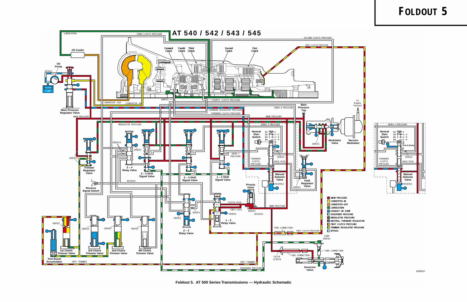
F
OLDOUT
5
Foldout 5. AT 500 Series Transmissions — Hydraulic Schematic
� ���
��
ForwardClutch
FourthClutch
ThirdClutch
SecondClutch
FirstClutch
THIRD CLUTCH PRESSURE
MAIN PRESSURE
FORWARD REGULATOR PRESSURE
DRIVE–2 PRESSURE
FOURTH CLUTCH PRESSURE
FORWARD CLUTCH PRESSURE
AT 540 / 542 / 543 / 545
ORIFICE
3 – 4Relay Valve
TrimmerRegulator
Valve
Main PressureRegulator Valve
Oil Cooler
ORIFICES
FILTERSUMP
OilPump
LUBRICATION
MAIN PRESSURE
CONVERTER – OUT
MODULATOR PRESSURE
CONVERTER – IN
BYPASS
ORIFICES
ORIFICE
2 – 3 ShiftSignal Valve
1 – 2 ShiftSignal Valve
3 – 4 ShiftSignal Valve
ManualSelector
Valve
RN1 – 41 – 31 – 21
PriorityValve
NeutralStart
Switch
MAIN PRESSURE
FORWARDCLUTCH
PRESSUREHOLD FEED
REVERSE
DRIVE–1PRESSURE ORIFICE
D1D2D3D4
GovernorValve
HoldRegulator
Valve
ModulatorValve
0.090"ORIFICE
ORIFICE
FIRST TRIMMER
GOVERNOR PRESSUREV03030.01
FIRST CLUTCH PRESSURE
VacuumModulatorORIFICE
TUBE CONNECTION
TUBE CONNECTIONFILTER
SCREEN
TUBE CONNECTION2 – 3
Relay Valve
1 – 2Relay Valve
ORIFICEREVERSE
FIRST FEEDORIFICE
ORIFICE
ORIFICE
CLUTCH FEED
1st ClutchTrimmer Valve
Trim BoostAccumulator
ORIFICE
3rd ClutchTrimmer Valve
2nd ClutchTrimmer Valve
ORIFICE
4th ClutchTrimmer Valve
ORIFICEORIFICE
FIRST TRIMMER
ReverseSignal Switch
REVERSE
MAIN PRESSURECONVERTER–INCONVERTER–OUTLUBRICATIONEXHAUST OR SUMPGOVERNOR PRESSUREMODULATOR PRESSURENEUTRAL, FORWARD REGULATORFIRST CLUTCH PRESSURETRIMMER REGULATOR PRESSURE
MainPressure
Tap
SECOND CLUTCH PRESSURE
DRIVE–3 PRESSURE
FIRST CLUTCH PRESSURE
BYPASS
ToEngineVacuum
DRIVE–2 PRESSURE
ManualSelector
Valve
RN1 – 4
2nd N (Park)
1 – 31 – 21Neutral
StartSwitch
FORWARDCLUTCH
PRESSUREHOLD FEED
REVERSE
ORIFICE
D1D2D3D4

�������
����
���������������������������
�
��
������
����
����
��������
���
���������
�������
�������
� �
���
�
����
��
���
�� �����
2 – 3 ShiftSignal Valve
2 – 3Relay Valve
1 – 2 ShiftSignal Valve
1 – 2Relay Valve
3 – 4Relay Valve
3 – 4 ShiftSignal Valve
ManualSelector
Valve
RN1 – 41 – 31 – 21
GovernorValve
HoldRegulator
Valve
TrimmerRegulator
Valve
Lockup ShiftValve
ModulatorValve
Main PressureRegulator Valve
Oil Cooler
PriorityValve
1st ClutchTrimmer Valve
Trim BoostAccumulator
ORIFICE
3rd ClutchTrimmer Valve
ORIFICES
2nd ClutchTrimmer Valve
ORIFICE
4th ClutchTrimmer Valve
ORIFICE
MAIN PRESSURECONVERTER–INCONVERTER–OUTLUBRICATIONEXHAUST OR SUMPGOVERNOR PRESSUREMODULATOR PRESSURENEUTRAL, FORWARD REGULATORFIRST CLUTCH PRESSURETRIMMER REGULATOR PRESSURE
0.090"ORIFICE
MainPressure
Tap
NeutralStart
Switch
ORIFICE
ORIFICE
ORIFICEReverseSignal Switch
D1D2D3D4
FILTERSUMP
OilPump
SECOND CLUTCH PRESSURE
LUBRICATIONTHIRD CLUTCH PRESSURE
MAIN PRESSURE
LOCKUP PRESSURE
CONVERTER – OUT MAIN PRESSURE
MAIN PRESSURE
FORWARD REGULATOR PRESSUREDRIVE–3 PRESSURE
DRIVE–2 PRESSURE
FIRST TRIMMER
GOVERNOR PRESSURE
FIRST TRIMMER
REVERSE
REVERSE
FORWARDCLUTCH
PRESSURE
FOURTH CLUTCH PRESSURE
V01295.02
HOLD FEED
FORWARD CLUTCH PRESSURE
MODULATOR PRESSURE
AT 1542 / 1545
REVERSE
DRIVE–1PRESSURE
CONVERTER – IN
CONVERTER – OUT
CONVERTER – IN
FIRST CLUTCH PRESSURE
FIRST CLUTCH PRESSURE
BYPASS
ORIFICE
VacuumModulator
ToEngineVacuum
ORIFICE
TUBE CONNECTION
TUBE CONNECTIONFILTER
SCREEN
FIRST FEED
CLUTCH FEED
BYPASS
ORIFICES
ORIFICE
ORIFICE
ORIFICE
TUBE CONNECTION
ORIFICE
ORIFICE
ForwardClutch
FourthClutch
ThirdClutch
SecondClutch
FirstClutch
LockupPressure
Tap
F
OLDOUT
6
Foldout 6. AT 1500 Series Transmissions — Hydraulic Schematic

Copyright © 1996 General Motors Corp. Foldout 7
AT 500, 1500 SERIES AUTOMATIC TRANSMISSIONS
A
1 – Nut,
3
⁄
8
-24 (6)
A
2 – Torque converter assembly (AT 543)3 – Spacer retainer (6) (earlier models)4 – Spacer (6)5 – Torque converter cover assembly6 – Self-locking nut,
5
⁄
16
-24 (24)
B
7 – Bearing race8 – Thrust bearing assembly9 – Bearing race
10 – Thrust bearing spacer (selective)11 – Converter turbine assembly12 – Rivet13 – Torque converter turbine14 – Torque converter turbine hub15 – Torque converter stator and bearing assembly16 – Torque converter stator assembly17 – Stator front side plate18 – Stator cam washer19 – Stator20 – Cam21 – Stator cam washer22 – Stator rear side plate23 – Flat head rivet (6)24 – Needle bearing assembly25 – Freewheel roller race26 – Freewheel roller (10)27 – Freewheel roller spring (10)28 – Bolt,
1
⁄
4
-20 x
5
⁄
8
inch (8)
C
29 – Lockstrip (4)30 – Torque converter pump hub31 – Gasket32 – Needle bearing assembly33 – Bearing race34 – Sealring35 – Torque converter pump assembly36 – Special bolt,
5
⁄
16
-24 x 1.36 inch (24)
Torque lb ft N·m
A
34–40 46–54
B
19–23 26–31
C
9–11 12–15
Legend for Foldout 7
B
1 – Torque converter assembly(AT 540, 542, 545, 1542, 1545)
2 – Oil pump and front support assembly3 – Front oil seal4 – Sealring5 – Pump body and gear assembly6 – Pump body assembly7 – Bushing (prebored) (for service only)8 – Pump body9 – Pump driven gear
10 – Pump drive gear11 – Bolt,
5
⁄
16
-18 x 1 inch (6) (8 on earlier models)
A
12 – Rubber coated washer (6) (8 on earlier models)13 – Sealring14 – Valve plug (earlier models)15 – Pin (earlier models)16 – Front support and bearing assembly17 – Front support assembly18 – Ground sleeve bushing*19 – Ground sleeve20 – Tapered expansion plug21 – Front support22 – Tapered expansion plug23 – Roller bearing24 – Snapring25 – Spring stop26 – Valve spring27 – Main-pressure regulator valve28 – Self-locking bolt,
5
⁄
16
-18 x 1
3
⁄
4
inch (3)**
A
29 – Self-locking bolt,
5
⁄
16
-18 x 1 inch (2)**
A
30 – Lockup valve (AT 1500 Series)31 – Lockup valve spring (AT 1500 Series)32 – Stop (AT 1500 Series)33 – Pin (AT 1500 Series)34 – Self-locking bolt,
5
⁄
16
-18 x 1
3
⁄
4
inch (9)
B
35 – Rubber coated washer (9)36 – Gasket37 – Thrust washer (selective)38 – Hook-type sealring (2)39 – Self-locking bolt, M6-1 (6)
C
***40 – Rubber-coated flat washer (6)
* Not present on AT 1500 Series models
** For later models, all five
5
⁄
16
-18 bolts are 1
3
⁄
4
inch long
*** Retarder models only
Torque lb ft N·m
A
15–20 20–27
B
13–16 18–22
C
9–10 12–14
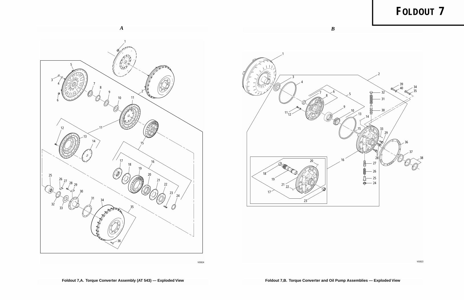
F
OLDOUT
7
Foldout 7,A. Torque Converter Assembly (AT 543) — Exploded View Foldout 7,B. Torque Converter and Oil Pump Assemblies — Exploded View
4
3
78
65
910
13
15
14
37
1
2
38
36
3329
3435
3940
19
1112
17
16
18
20
31
30
27
28
26
252421
22
32
V03023
23
A B
��������������������
V03024
10
1112
1314
1617
3431
30
29
35
36
282726
25
1819
20
2122
2324
15
3233
116
4
5
3
98
2
1
7

F
OLDOUT
8
1
2
3
4
6
5
1817
109
19
2524
23
32
33
34
26
27
7
28
29
30
21
22
20
12
16
8
15
14
11
13
1 – Front stator (models with retarder)2 – Hook-type sealring3 – Snapring (earlier models)4 – PTO drive gear (earlier models)5 – Wave-type snapring (earlier models)6 – Forward clutch and turbine shaft assembly
(with PTO)7 – Housing and shaft assembly8 – Forward clutch housing assembly9 – Forward clutch housing
10 – Ball11 – Forward clutch assembly (models with retarder)12 – Hook-type sealring (models with retarder)13 – Forward clutch housing and turbine shaft assembly
(models with retarder)14 – Forward clutch housing assembly
(models with retarder)15 – Ball, 3⁄16 inch diameter (models with retarder)16 – Hook-type sealring (models with retarder)17 – Piston inner sealring18 – Piston outer sealring19 – Forward clutch piston (selective)
Piston A* 0.700–0.710 inch (17.78–18.03 mm)Piston B* 0.726–0.736 inch (18.44–18.69 mm)Piston C* 0.752–0.762 inch (19.10–19.36 mm)Piston EF** 0.984–1.010 inch (25.00–25.65 mm)Piston E** 1.010–1.046 inch (25.66–26.56 mm)Piston DE** 1.046–1.072 inch (26.57–27.22 mm)
* earlier models** later models
20 – Clutch return spring (16)21 – Spring retainer22 – Snapring23 – Thrust bearing race24 – Thrust needle bearing25 – Thrust bearing race26 – Forward clutch hub27 – External-tanged wave clutch plate (later models)28 – External-tanged clutch plate (4)*29 – Internal-splined clutch plate (5)30 – Fourth clutch drive hub31 – Snapring32 – Snapring (later models)33 – PTO drive gear (later models)34 – Thrust washer35 – Retarder housing assembly (models with retarder)36 – Rear stator (models with retarder)37 – Retarder housing (models with retarder)38 – Screw (4) 10–12 lb ft (14–16 N·m)
(models with retarder)
Foldout 8. Forward Clutch and Turbine Shaft — Exploded View
V03036
36
35
37
38
31

Copyright © 1996 General Motors Corp. Foldout 9
AT 500, 1500 SERIES AUTOMATIC TRANSMISSIONS
A
1 – Snapring (models without retarder)2 – Clutch backplate (models without retarder)3 – Internal-splined clutch plate (5)4 – External-tanged clutch plate (5)5 – Snapring6 – Spring retainer7 – Piston return spring (16)8 – Fourth clutch piston (selective)
Piston
A
* 0.700–0.710 inch (17.78–18.03 mm)Piston
B*
0.726–0.736 inch (18.44–18.69 mm)Piston
C*
0.752–0.762 inch (19.10–19.36 mm)Piston
EF
**0.984–1.010 inch (25.00–25.65 mm)Piston
E
** 1.010–1.046 inch (25.66–26.56 mm)Piston
DE
**1.046–1.072 inch (26.57–27.22 mm)9 – Piston outer sealring
10 – Piston housing inner sealring11 – Fourth clutch housing assembly12 – Ball13 – Fourth clutch housing
* earlier models** later models
Legend for Foldout 9
B
1 – Snapring2 – Third clutch backplate
(Ident. 4)* 0.416–0.426 inch (10.57–10.82 mm)
(
Ident.
❏
) 0.419–0.429 inch (10.64–10.90 mm)3 – Internal-splined clutch plate (3)4 – External-tanged clutch plate (3)5 – Snapring
Color code white 0.148–0.150 inch (3.75–3.81
mm)Color code yellow 0.152–0.154 inch (3.86–3.91 mm)Color code green 0.155–0.157 inch (3.93–3.98 mm)Color code red 0.158–0.160 inch (4.01–4.06 mm)
6 – Self-locking retainer washer (4)7 – Spring retainer8 – Piston return spring (12)9 – Third clutch piston
10 – Piston inner sealring11 – Piston outer sealring12 – Hook-type sealring (2)13 – Center support and bushing assembly14 – Bushing15 – Center support16 – Piston outer sealring17 – Piston inner sealring18 – Second clutch piston19 – Piston return spring (12)20 – Spring retainer21 – Self-locking retainer washer (4)22 – Snapring23 – External-tanged clutch plate (3)24 – Internal-splined clutch plate (3)25 – Second clutch backplate
(Ident. 5)* 0.429–0.439 inch (10.90–11.15 mm)(Ident.
❏
) 0.419–0.429 inch (10.64–10.90 mm)
* For models prior to S/N 3210668026
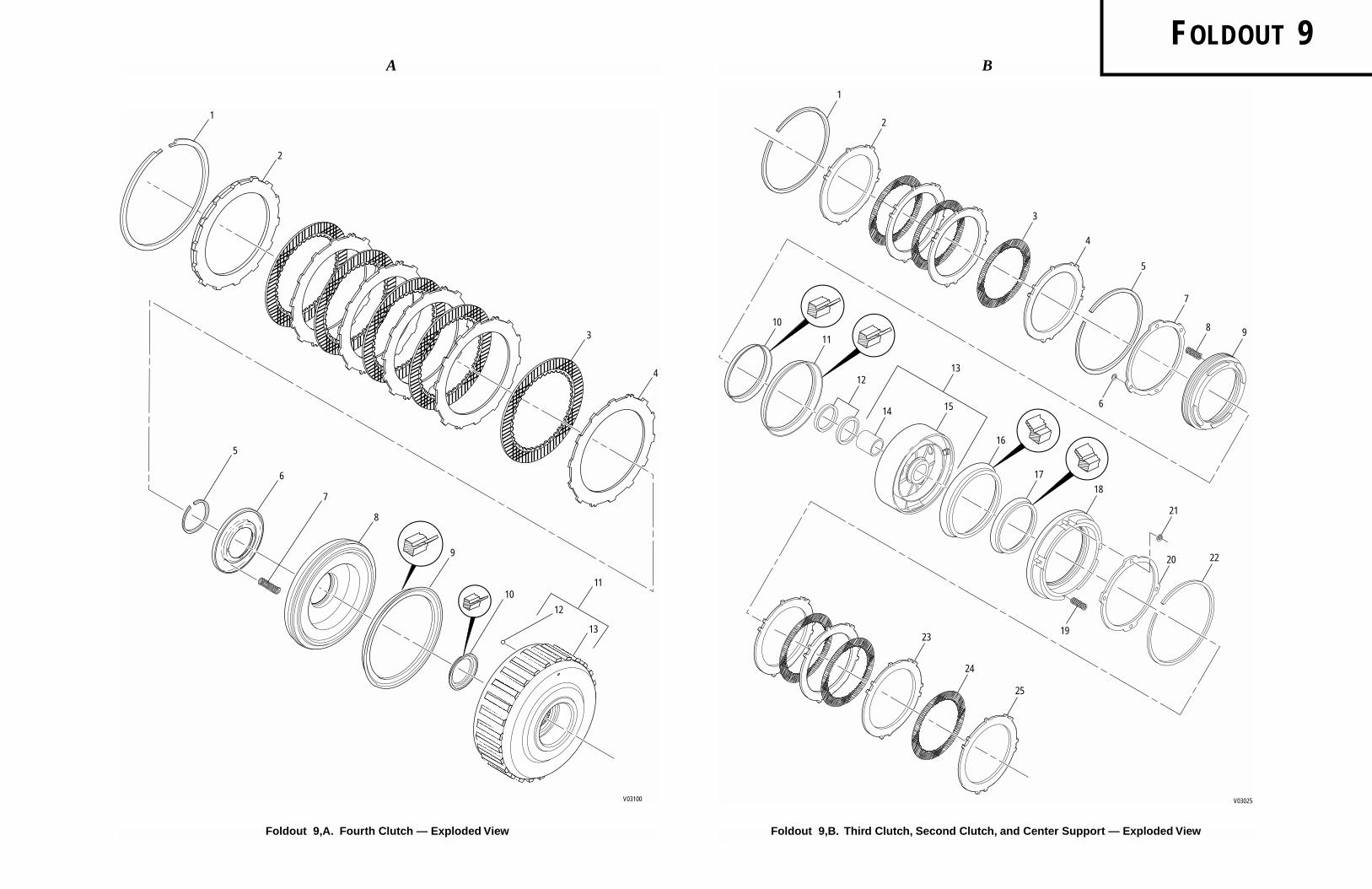
B
F
OLDOUT
9
Foldout 9,A. Fourth Clutch — Exploded View
V03100
1
2
3
4
8
7
6
9
5
10
13
11
12
V03025
1
2
3
4
5
7
8
6
910
11
14 15
16
17
18
21
19
2220
23
24
25
1213
Foldout 9,B. Third Clutch, Second Clutch, and Center Support — Exploded View
A

AT 500, 1500 SERIES AUTOMATIC TRANSMISSIONS
Legend for Foldout 10
A1 – Sun gear shaft assembly2 – Bushing (2) (service only)3 – Sun gear shaft4 – Transmission main shaft5 – Thrust washer6 – Front planetary sun gear7 – Thrust washer8 – Front planetary carrier assembly9 – Pinion pin (4)
10 – Bronze thrust washer (8)11 – Steel thrust washer (8)12 – Pinion (matched set of 4)13 – Needle roller bearing (80)14 – Carrier and bushing assembly15 – Bushing16 – Thrust washer17 – Snapring18 – Front planetary ring gear19 – Center sun gear20 – Center planetary carrier assembly21 – Center planetary carrier22 – Bronze thrust washer (8)23 – Steel thrust washer (8)24 – Pinion (matched set of 4)25 – Needle roller bearing (76)26 – Pinion pin (4)27 – Thrust washer28 – Planetary connecting drum29 – Snapring30 – Center planetary ring gear31 – Rear planetary sun gear32 – Needle thrust bearing33 – Thrust bearing race34 – Spiral retainer ring35 – Snapring36 – Rear planetary carrier assembly
Copyrigh
37 – Rear planetary carrier38 – Bronze thrust washer (8)39 – Steel thrust washer (8)40 – Pinion (matched set of 4)41 – Needle roller bearing (76)42 – Pinion pin (4)43 – Snapring44 – Ball bearing45 – Output shaft assembly46 – Shaft and bushing assembly47 – Bushing48 – Output shaft49 – Lube orifice plug50 – Governor drive spring pin51 – Spiral retainer ring (prior to S/N 5071)52 – Spacer washer (prior to S/N 5071)53 – Rear planetary ring gear (prior to S/N 5071)54 – Spacer washer (prior to S/N 5071)
B
1 – Snapring2 – Backplate (selective)
(Ident. 1, 4) 0.683–0.693 inch (17.34–17.60 mm)(Ident. 2, 5, or no stamp) 0.647–0.657 inch(16.43–16.68 mm)(Ident. 3, 6) 0.611–0.621 inch (15.51–15.77 mm)
3 – Internal-splined clutch plate (7)4 – External-tanged clutch plate (7)5 – Rear planetary ring gear6 – Snapring7 – Spring retainer8 – Piston return spring (22)9 – First clutch piston
10 – Piston outer sealring11 – Piston inner sealring
t © 1996 General Motors Corp. Foldout 10
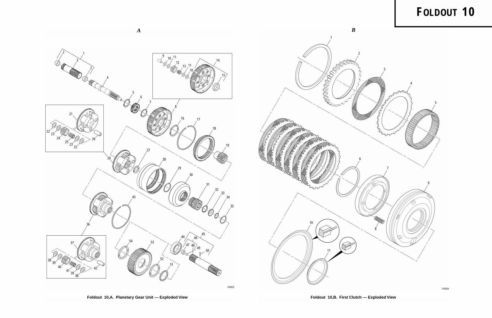
B
F
OLDOUT
10
Foldout 10,A. Planetary Gear Unit — Exploded View
V03032
910 11
16
28
30
53
4950
43
52
47
44
38
42
37
39
3938
4140
54
51
48
29
3132
3334
35
27
20
7
17
18
19
8
65
4
2
2
312
13 1110
15
14
4645
1
36
22
26
21
23
2322
2524
1
2
3
4
5
6
7
9
8
10
11
V03026
Foldout 10,B. First Clutch — Exploded View
A

F
OLDOUT
11
3132
33
35
3029
2324
25
34
2221 18
1920
1716
1415
1312
3738
4241
40 39
36
2728
76
78
2
1
3
11
7273
747069
6867
6664
6362
6160
5857
56
5051
4847
46
55
53
5483
77
78
9
781
80
826 5
4
26
59
65
52
44
45
43
71
75
79
49
V03033
1 – Control valve body assembly2 – Separator plate3 – Bolt, 1⁄4-20 x 13⁄4 (3) A4 – Adjusting ring (earlier models)5 – Valve stop (earlier models)6 – Washer (earlier models)7 – Valve spring8 – Modulator valve (earlier models)9 – Retainer pin
10 – Modulator valve body11 – Control valve body12 – Third clutch trimmer valve13 – Trimmer plug14 – Trimmer spring15 – Valve stop16 – First clutch trimmer valve17 – Trimmer plug18 – Trimmer outer spring19 – Trimmer inner spring (after S/N 34500)20 – Valve stop21 – Second clutch trimmer valve22 – Trimmer plug23 – Trimmer spring24 – Trimmer inner spring25 – Valve stop26 – Valve stop (after S/N 3210274681)27 – Spring (after S/N 3210274681)28 – Trim Boost accumulator valve
(after S/N 3210274681)29 – Fourth clutch trimmer valve30 – Trimmer plug31 – Trimmer outer spring32 – Trimmer inner spring (after S/N 34500)33 – Valve stop34 – Trimmer cover35 – Bolt, 1⁄4-20 x 3⁄4 (9) (8, earlier models) A36 – Retainer pin37 – 2–3 relay valve38 – Relay valve spring39 – Valve stop40 – 1–2 relay valve41 – Relay valve spring42 – Spacer43 – Valve stop
44 – Priority valve spring45 – Priority valve46 – Hold regulator valve47 – Valve spring48 – Valve stop49 – Valve plug (earlier models)50 – Washer51 – Adjusting ring52 – Retainer pin53 – Selector valve54 – 1–2 shift signal valve55 – 1–2 modulator valve56 – Valve spring57 – Valve stop58 – Adjusting ring59 – Retainer pin60 – 2–3 shift signal valve61 – 2–3 modulator valve62 – Valve spring63 – Valve stop64 – Adjusting ring65 – Retainer pin66 – 3–4 shift signal valve67 – 3–4 modulator valve68 – Valve spring69 – Valve stop70 – Adjusting ring71 – Retainer pin72 – 3–4 relay valve73 – Relay valve spring74 – Valve stop75 – Retainer pin76 – Trimmer regulator valve77 – Valve spring78 – Valve stop79 – Retainer pin80 – Retained modulator actuator rod81 – Modulator valve82 – Adjusting ring83 – Valve assist spring (assemblies with 2nd gear start
provision)
Torque lb ft N·m
A 8–12 10–16
Foldout 11. Main Control Valve Body Assembly — Exploded View

AT 500, 1500 SERIES AUTOMATIC TRANSMISSIONS
Legend for Foldout 12
A1 – Gasket2 – Power takeoff cover3 – Bolt, 3⁄8-16 x 3⁄4 (6) A4 – Drive screw5 – Nameplate6 – Transmission housing assembly7 – Vent assembly8 – Pipe plug, 1⁄8 inch B9 – Internal snapring
10 – Transmission housing and pin assembly11 – Transmission housing12 – Governor support pin13 – Pipe plug, 1⁄8 inch B14 – Neutral start switch plug, 3⁄4 C15 – Washer16 – Coil insert (4) (AT 543)17 – Neoprene breather shroud18 – Governor assembly19 – Governor service kit20 – Governor weight pin (2)21 – Cover gasket22 – Governor cover23 – Bolt, 5⁄16-18 x 9⁄16 (4) A24 – Bolt, 5⁄16-18 x 9⁄16 D25 – Modulator retainer26 – Vacuum modulator27 – Modulator sealring28 – Modulator valve actuating rod (later models)
* 48–60 lb in.
B1 – Governor drive gear2 – Speedometer drive gear3 – Spacer (selective)4 – Ball bearing5 – Snapring6 – Oil seal7 – Output flange washer8 – Bolt, Type BH Place,1⁄2-20 x 11⁄2 A9 – Speed sensor wheel (for applications using
electronic speedometer)10 – First clutch tube (use with pan 33)11 – First clutch tube (use with pan 26)12 – Governor circuit screen13 – Governor feed tube (2)14 – Bolt, 1⁄4-20 x 3 (2) B15 – Bolt, 1⁄4-20 x 23⁄4 (earlier models) B16 – Detent roller and spring17 – Bolt, 1⁄4-20 x 13⁄4 B18 – Intake tube (fitting C)
Torque lb ft N·mA 15–20 20–27B * 5.5–6.7C 25–45 33–60D 10–16 14–22
Copyright ©
19 – Filter kit20 – Sealring21 – Filter assembly22 – Pan gasket23 – Washer-head screw, 5⁄16-18 x 5⁄8 D24 – Drain plug washer25 – Drain plug E26 – Shallow oil pan and magnet assembly27 – Magnet28 – Washer-head screw, 5⁄16-18 x 5⁄8 (21) D*29 – Drain plug E30 – Drain plug washer31 – Washer-head screw, 5⁄16-18 x 5⁄8 (21) D*32 – Tube plug33 – Deep oil pan and magnet assembly34 – Magnet35 – Washer-head screw, 5⁄16-18 x 5⁄8 D36 – Filter kit37 – Sealring38 – Filter assembly39 – Pan gasket40 – Intake tube (fitting C)41 – Filter spacer42 – Washer-head screw, 5⁄16-18 x 5⁄8 D or
Bolt, 5⁄16-18 x 21⁄4 (earlier models) D43 – Plain washer, 5⁄16 inch (earlier models)44 – Filter kit45 – Sealring46 – Filter assembly47 – Pan gasket48 – Intake tube (fitting C)49 – Filter spacer50 – Bolt, 1⁄4-20 x 21⁄4 (16) B
(earlier models use (18) or (17)) B51 – Bolt, center support, 3⁄8-16 F, 7⁄16-20G52 – Plain washer53 – Governor pressure check ball (earlier models)54 – Selector lever detent (models with Park position)55 – Selector lever detent (models without Park position)56 – Locknut, 3⁄8-24 H57 – Selector shaft retainer pin58 – Selector shaft kit59 – Selector shaft nut (Refer to Caution, Paragraph 3–12a) E60 – Selector shaft61 – Seal
* Must maintain a minimum of 5 lb ft (7 N·m) of torque after thepan gasket has taken a set.
Torque lb ft N·mA 102–121 138–164B 8–12 10–16C 90–100 122–136D 10–15 14–20E 15–20 20–27F 39–46 53–62G 67–80 91–108H 15–25 20–34
1996 General Motors Corp. Foldout 12

F
OLDOUT
12
Foldout 12,A. Transmission Housing, Governor, and Vacuum Modulator — Exploded View
12
52
16
14
10
11
17
51
57
5013
15
53
5960
58 611
23
45
67
89
5655
54
48
45
4644
47
49 36
4342
3334
3132
30 29
37
40 41
35
38
39
19
20 18
21
2223
24 2527
26
28
V03028
����������������
������������������������������������������������������������������������
��������������������
17
7
7
6
3
2425
8
12
2
1
5
26
19
22
1514
21
18
23
20
2728
4
16
13
1110
9
8
12
1514
16
13
1110
9
V01315
AT 1500 SERIES
Foldout 12,B. Oil Pan, Filter, Governor, and Speedometer Drives — Exploded View

Copyright © 1996 General Motors Corp. Foldout 13
AT 500, 1500 SERIES AUTOMATIC TRANSMISSIONS
1 – Gasket2 – Jumper tube (2)3 – Complete retarder control assembly4 – Bolt,
1
⁄
4
-20 x 1
1
⁄
4
inch (4)
A
5 – Flat washer,
1
⁄
4
inch (4)6 – Transfer plate assembly7 – Solenoid (2)8 – Solenoid connector (2)9 – Snapring
10 – Wire feedthrough seal11 – Retarder wiring harness12 – Pipe plug,
1
⁄
16
inch (2)
B
13 – Retaining pin (2)14 – Transfer plate15 – Pipe plug,
1
⁄
2
-14
C
16 – Gasket (2)17 – Separator plate18 – Retarder control valve body assembly19 – Plug20 – Retarder priority valve21 – Spring22 – Pin (2)23 – Retarder control valve body24 – Retarder regulator valve25 – Spring26 – Capacity pin27 – Plug28 – Retarder autoflow valve29 – Spring30 – Plug31 – O-ring32 – Snapring33 – O-ring34 – To-cooler adapter35 – To-cooler hose assembly36 – Bolt,
3
⁄
8
-16 x 4
1
⁄
4
inch (4)
D
37 – Main feed adapter38 – Main feed hose assembly
* 35–50 lb in.
Torque lb ft N·m
A
8–12 10–16
B
* 4–5
C
16–20 22–27
D
26–32 36–43
Legend for Foldout 13

V03027����������������������������������������������������������������������������������������������������������������������������������������������������������������������������������������������������������������������������������������������������������������������������������������������������������������������������������������������������
37
38
36
34
33
35
4
1
7
16
17
16
18
19
20
21
22
89
1213
1110
15
23
14
6
5
2
3
24
28
29
30
31
32
25
26
27
38REF
F
OLDOUT
13
Foldout 13. Retarder Control Components