tech data 1500 gpm - for power island system rev.01
DESCRIPTION
erTRANSCRIPT

7/17/2019 Tech Data 1500 Gpm - For Power Island System Rev.01
http://slidepdf.com/reader/full/tech-data-1500-gpm-for-power-island-system-rev01 1/101
EL
DI
C
CSTCTRIC
ESEL FI
JOCKE
AL
T IRE PU
E PUM
PUMP
I
FIOP.Cap.
.Cap.1
.Cap.12
E
,B1500 G
00 Gp
M3/H
L
OB
m @ 1
@ 150
11 Bar
07
0707
D
L Bar To
Psi Tot
Total H
/17/2
/17/2 /17/2
R
N
al Hea
l Head
ead
14
1414
A

7/17/2019 Tech Data 1500 Gpm - For Power Island System Rev.01
http://slidepdf.com/reader/full/tech-data-1500-gpm-for-power-island-system-rev01 2/101
Project : Coal Fired Power Station, Babelan
INDUSTRIAL DIVISION
No
1 1 Set
1 "Aurora" Horizontal Split Case
Model : 6-481-14HH/Single Stage
Pump Material Design, Casing : Cast Iron, Impeller : Bronze,
Shaft : Carbon Steel with Bronze Sleeve, Shaft Seal : Gland Packing
Pump Accessories : Suction and Discharge Gauges, Automatic Air
Release Valve, Casing Relief Valve
1 "Factory Choice" ODP Electric Motor 200 HP @ 2950 Rpm
With 380V/ 3Ph/ 50Hz
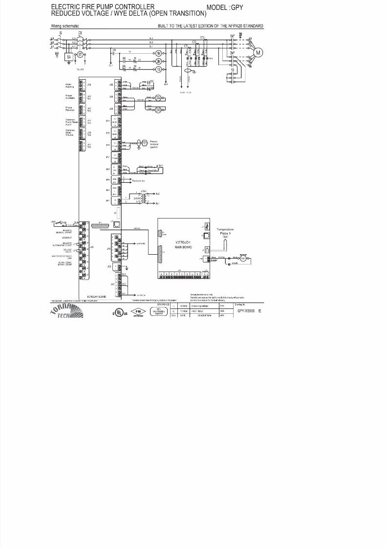
1 "Tornatech" Electric Fire Pump Controller
Model : GPY
2 1 Set
1 "Aurora" Horizontal Split Case
Model : 6-481-14HH/single stage
Pump Material Design, Casing : Cast Iron, Impeller : Bronze,
Shaft : Carbon Steel with Bronze Sleeve, Shaft Seal : Gland Packing
Pump Accessories : Suction and Discharge Gauges, Automatic Air
Release Valve, Main Relief Valve, Enclosed Waste Cone
1 "CLARKE" Diesel Eng ine JU6H-UF62, 240 HP @ 2600 RpmHeat Exchanger Cooling System with cooling loop and double starter
twin solenoid
Engine accessories : Batteries Cables, Battery rack, Silencer,
Flexible Exhaust Connector, Fuel Tank (Supplied by Import)
1 "Tornatech" Diesel Fire Pump Controller
Model : GPD
ELECTRIC FIRE PUMP UL/FM, NFPA-20 STANDARD
Cap. 1500 GPM @ 10 Bar Total Head
DIESEL FIRE PUMP UL/FM, NFPA-20 STANDARD
Cap. 1500 GPM @ 150 Psi Total Head
Pump and Accessori es For Power Island Systems
Pump and Accessori es For Power Island Systems
Al ternative (Ready Stock)
Qty Description
SUBJECT : TECHNICAL REVIEW

7/17/2019 Tech Data 1500 Gpm - For Power Island System Rev.01
http://slidepdf.com/reader/full/tech-data-1500-gpm-for-power-island-system-rev01 3/101
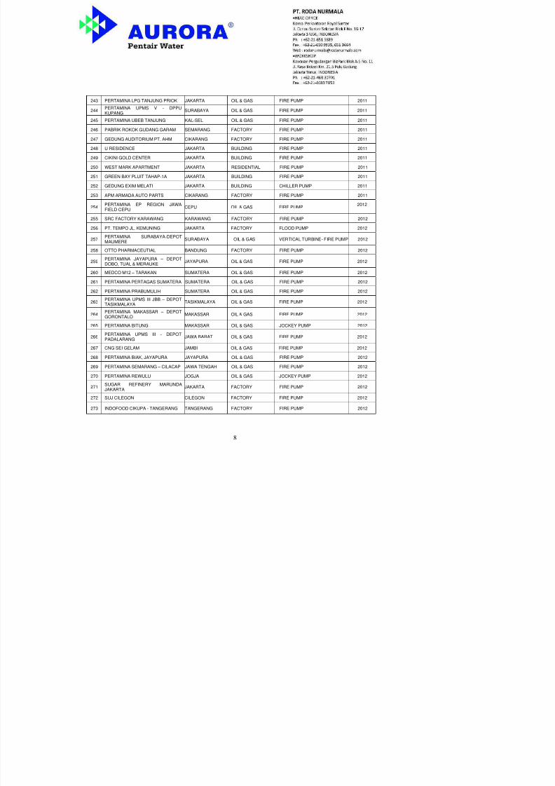
REFERENCE LIST AURORA PUMPIN INDONESIA
NO PROJECT NAME LOCATION LINE DUTY YEAR1 HINDOLI PALEMBANG BUILDING FIRE PUMP 1988
2 SEMEN CIBINONG CIBINONG INDUSTRY FIRE PUMP, TRANSFER PUMP 1999
3 MACRO DENPASAR BUILDING FIRE PUMP 1999
4 BATU HIJAU WTP SECTION I - MINING FIRE PUMP 1999
5 PLAZA DAGO BANDUNG BUILDING FIRE PUMP 1999
6 MAKRO JAKARTA BUILDING FIRE PUMP 1999
7 MAKRO MEDAN BUILDING FIRE PUMP 20008 SCHLUMBERGER BALIKPAPAN BUILDING FIRE PUMP 2000
9 BATU HIJAU WTP SECTION II - MINING FIRE PUMP 2000
10 MULAWARMAN UNIV. PACKAGED I - BUILDING FIRE PUMP 2000
11 MULAWARMAN UNIV. PACKAGED II - BUILDING FIRE PUMP 2000
12 MULAWARMAN UNIV.PACKAGED III - BUILDING FIRE PUMP 2000
13 GS BATTERY JAKARTA FACTORY FIRE PUMP 2000
14 AUTO 2000 TEBET JAKARTA SHOWROOM FIRE PUMP 2001
15 GLOBAL AGROTEK JAKARTA BUILDING FIRE PUMP 200216 MALL FANTASI BALIKPAPAN BUILDING FIRE PUMP 2002
17 TEMPO MEDAN WAREHOUSE FIRE PUMP 2002
18 SUSU CAIR INDOMILK - FACTORY FIRE PUMP 2002
19 PRESIDEN HOTEL JAKARTA BUILDING FIRE PUMP 2002
20 BINTARO TRADE CENTER JAKARTA BUILDING FIRE PUMP 2003
21 MALL KAREBOSI MAKASSAR BUILDING FIRE PUMP 2003
22 MULIA TOWER JAKARTA BUILDING FIRE PUMP 2003
23 BNI’46 LADA JAKARTA BUILDING FIRE PUMP 200324 EXSPAN KAJI JAKARTA BUILDING FIRE PUMP 2003
25 WTC MANGGA DUA JAKARTA BUILDING PLUMBING 2003
26 TAMAN IMPIAN JAYA ANCOL JAKARTA BUILDING FIRE PUMP 2003
27 SEMEN CIBINONG CIBINONG CEMENT INDUSTRY SEWAGE PUMP 2003
28 PANGRANGO PLAZA BOGOR BUILDING FIRE PUMP 2003

7/17/2019 Tech Data 1500 Gpm - For Power Island System Rev.01
http://slidepdf.com/reader/full/tech-data-1500-gpm-for-power-island-system-rev01 4/101
37 PUSAT DAGANG INVESTASI BATAM BUILDING FIRE PUMP 2004
38 BELLAGIO RESIDENCE JAKARTA BUILDING FIRE PUMP 2004
39 PONDOK INDAH MALL 2 JAKARTA BUILDING FIRE PUMP, CHILLER PUMP 2004
40 SAN MIGUEL JAKARTA FACTORY FIRE PUMP 200441 BAYER MEDAN FACTORY FIRE PUMP 2005
42 BAYER SURABAYA FACTORY FIRE PUMP 2005
43 MEGA GLODOK KEMAYORAN JAKARTA BUILDING FIRE PUMP 2005
44 SEMEN PADANG PADANG CEMENT INDUSTRY COOLING TOWER 2005
45 SEMEN CIBINONG CIBINONG CEMENT INDUSTRY WATER INJECTION 2005
46 SEMEN CIBINONG CIBINONG CEMENT INDUSTRY WATER SPRAY 2005
47 PERTAMINA PRABUMULIH PRABUMULIH OIL & GAS FIRE PUMP 2005
48 - - - FIRE PUMP 200549 BG JUNCTION / BUBUTAN SURABAYA BUILDING CHILLER & BOOSTER 2005
50 BAYER JAKARTA FACTORY VERTICAL TURBINE FIREPUMP 2005
51 BPKP PRAMUKA JAKARTA BUILDING FIRE PUMP 2005
52 BATAM CITY SQUARE BATAM BUILDING FIRE PUMP 2005
53 MECOINDO CIKARANG FACTORY FIRE PUMP 2006
54 - - OIL & GAS FIRE PUMP 2006
55 GRIYA JENGGALA JAKARTA RESIDENTIAL FIRE PUMP 2006
56 SUDIRMAN PARK JAKARTA BUILDING FIRE PUMP 2006
57 PEARL GARDEN JAKARTA BUILDING FIRE PUMP 2006
58 MODERN GOLF APARTEMENT TANGERANG BUILDING FIRE PUMP 2006
59 CITY HOME – KLP. GADING JAKARTA BUILDING FIRE PUMP 2006
60 ISLAMIC CENTER JAKARTA BUILDING FIRE PUMP 2006
61 INDONESIA NS FACTORY JAKARTA FACTORY FIRE PUMP 2006
62 PLAZA CIBUBUR JAKARTA BUILDING FIRE PUMP 2006
63 SUDIRMAN PLAZA JAKARTA BUILDING FIRE PUMP 2006
64 WISMA 76 JAKARTA BUILDING FIRE PUMP 2006
65 GRAND INDONESIA JAKARTA BUILDING FIRE PUMP, CHILLER PUMP,PLUMBING PUMP
2006
66 NUSA 2 GOLF RESIDENT BALI BUILDING FIRE PUMP 2006
68 PT. PJB UP MUARAKARANG JAKARTA POWER PLANT FIRE PUMP 2006
69 LAMONGAN INTEGRATED LAMONGAN SHORE BASE FIRE PUMP 2006

7/17/2019 Tech Data 1500 Gpm - For Power Island System Rev.01
http://slidepdf.com/reader/full/tech-data-1500-gpm-for-power-island-system-rev01 5/101
77 GRAND INDONESIA JAKARTA BUILDING FIRE PUMP 2006
78 KEDUTAAN BELANDA JAKARTA BUILDING FIRE PUMP 2006
79 HARDA BANK JAKARTA BUILDINGVERTICAL TURBINE FIREPUMP 2006
80 MENARA PRIMA JAKARTA BUILDING FIRE PUMP 2006
81 WISMA PONDOK INDAH JAKARTA BUILDING FIRE PUMP, CHILLER PUMP 2006
82 SEMEN PADANG PADANG CEMENT INDUSTRY HVAC PUMP 2006
83 ITC KOPO BANDUNG BUILDING FIRE PUMP 2006
84 THE EAST JAKARTA BUILDING FIRE & CHILLER PUMP 2006
85 PERTAMINA SAGATA KALIMANTAN OIL & GAS FIRE PUMP 2006
86 HOLCIM INDONESIA JAKARTA CEMENT INDUSTRY REGENERATIVE TURBINE PUMP 2006
87 SPRING HILL GOLF RESIDENCE JAKARTA RESIDENTIAL FIRE PUMP 2006
88 HOLCIM INDONESIA JAKARTA CEMENT INDUSTRY REGENERATIVE TURBINE PUMP 2006
89 JACC JAKARTA BUILDING FIRE PUMP 2006
90 ETERNIT GRESIK GRESIK FACTORY FIRE PUMP 2006
91 PLAZA ASIA TASIKMALAYA TASIKMALAYA BUILDING CHILLER PUMP 2006
92 IPEKA SCHOOL JAKARTA BUILDING FIRE PUMP 2006
93 PLAZA ASIA TASIKMALAYA TASIKMALAYA BUILDING PLUMBING PUMPSUBMERSIBLE PUMPDEEP WELL PUMP
2007
94 TOYOTA ASTRA MOTOR JAKARTA FACTORY FIRE PUMP 2007
95 CARREFOUR CIBINONG BANDUNG BUILDING FIRE PUMP 2007
96 CARREFOUR KIARA CONDONGMALL BANDUNG BUILDING FIRE PUMP 2007
97 PERFETI VAN MELLE JAKARTA FACTORY FIRE PUMP 2007
98 DATA CENTER SURABAYA BUILDING FIRE PUMP 2007
99 TOYOTA ASTRA MOTOR JAKARTA FACTORY CHILLER PUMP 2007
100 GRAND INDONESIA JAKARTA BUILDINGCHILLER PUMP APARTMENT,CONVENTION HALL 2007
101 CNOOC OFFCHORE OFFSHORE OIL RIG VERTICALTURBINESEA WATER FIRE PUMP 2007
102 PASAR BARU SQUARE BALIKPAPAN HOTEL AND MALL FIRE PUMP 2007
103 SEMEN PADANG PADANG CEMENT INDUSTRY HVAC PUMP 2007
104 NESTLE PASURUAN PASURUAN FACTORY FIRE PUMP 2007

7/17/2019 Tech Data 1500 Gpm - For Power Island System Rev.01
http://slidepdf.com/reader/full/tech-data-1500-gpm-for-power-island-system-rev01 6/101
111 WATERPLACE RESIDENCE SURABAYA BUILDING FIRE PUMP 2007
112 SEASON CITY JAKARTA BUILDING FIRE PUMP 2007
113 HOTEL MALEOSAN MANADO BUILDING FIRE PUMP 2007
114 APARTMENT BSB BALIKPAPAN BUILDING FIRE PUMP 2007115 HOLCIM INDONESIA JAKARTA BUILDING WATER SPRAY 2008
116 GRAHA 165 JAKARTA BUILDING CHILLER PUMP 2008
117 ARKADIA OFFICE JAKARTA BUILDING FIRE PUMP 2008
118 SAINATH OFFICE JAKARTA BUILDING FIRE PUMP 2008
119 GRAND CITY SURABAYA SURABAYA BUILDING CHILLER PUMP 2008
120 KEM TOWER KEMAYORAN JAKARTA BUILDINGPLUMBING PUMP,CHILLER PUMP,SUBMERSIBLE PUMP
2008
121 THE ADHIWANGSA RESIDENCE SURABAYA RESIDENTIAL FIRE PUMP 2008
122 DAPENRA JAKARTA BUILDING FIRE PUMP 2008
123 LUCKY SQUARE MALL BANDUNG BUILDING FIRE PUMP 2008
124 BEST WESTERN BALI HOTEL BALI BUILDING FIRE PUMP 2008
125 ASTON VERANDA HOTEL JAKARTA BUILDING FIRE PUMP 2008
126 SEMEN PADANG PADANG CEMENT INDUSTRY HVAC PUMP 2008
127 HOLCIM INDONESIA CILACAP CEMENT INDUSTRY WATER SPRAY 2008
128 CYBER-2 JAKARTA OFFICE FIRE PUMP 2008
129 HOTEL HILTON BANDUNG HOTEL FIRE PUMP 2008
130 SUDIRMAN TOWER JAKARTA BUILDING FIRE PUMP 2008
131 FREEPORT IRIAN JAYA MINING CIRCULATION PUMP 2008
132 GRAHA PENA SURABAYA BUILDING FIRE PUMP 2008
133 BPK PENABUR - KELAPA GADING JAKARTA BUILDING FIRE PUMP 2008
134 FLOUR MILLS - CILEGON CILEGON FACTORY FIRE PUMP 2008
135 MEDCO ENERGI SUMATERA OIL & GAS FIRE PUMP 2008
136 PARAGON CITY SEMARANG BUILDING FIRE PUMP 2008
137 MENARA MTH JAKARTA BUILDING FIRE PUMP 2008
138 QATAR EMBASSY JAKARTA BUILDING FIRE PUMP 2008
139 CYBER-2 JAKARTA OFFICE HVAC PUMP, PLUMBING PUMP 2008
140 MEDCO II SUMATERA OIL & GAS FIRE PUMP 2008

7/17/2019 Tech Data 1500 Gpm - For Power Island System Rev.01
http://slidepdf.com/reader/full/tech-data-1500-gpm-for-power-island-system-rev01 7/101
148 TRANS KALLA MAKASSAR BUILDING FIRE PUMP 2009
149 PUPUK KUJANG CIKAMPEK FACTORY HYDROMATIC PUMP 2009
150 INDOSAT SUKABUMI BUILDING FIRE PUMP 2009
151 IT BATAM BATAM BUILDING FIRE PUMP 2009152 SAMPOERNA STRATEGIC SQUARE JAKARTA BUILDING HOT WATER PUMP 2009
153 KANTOR PERWAKILAN PEMDASULUT JAKARTA BUILDING FIRE PUMP 2009
154 LOMBOK AIRPORT LOMBOK BUILDING FIRE PUMP 2009
155 LAN SAMARINDA SAMARINDA BUILDING FIRE PUMP 2009
156 CENTRAL PARK JAKARTA BUILDING HVAC PUMP 2009
157 OFFICE KRAMAT RAYA JAKARTA BUILDING FIRE PUMP 2009
158 BINUS BOARDING HOUSE JAKARTA BUILDING FIRE PUMP 2009
159 BANDARA KUALANAMU MEDAN BUILDING FIRE PUMP, CHILLER PUMP,PLUMBING PUMP 2009
160 PPPK PETRA SURABAYA BUILDING FIRE PUMP 2009
161 PUSDIKLAT MAHKAMAH AGUNG JAKARTA BUILDING FIRE PUMP 2009
162 WILMAR NABATI INDONESIA GRESIK INDUSTRY FIRE PUMP 2009
163 PUSDIKLAT MAHKAMAH AGUNG BOGOR BUILDING FIRE PUMP 2009
164 PERTAMINA ACEH EP RANTAU ACEH OIL & GAS FIRE PUMP 2009
165 DINAS PEMADAM KEBAKARAN-LEBAK BULUS JAKARTA BUILDING FIRE PUMP 2009
166 TEMPO SCAN TOWER JAKARTA BUILDING FIRE PUMP, CHILLER PUMP,PLUMBING PUMP 2010
167 CIK DITIRO APARTMENT JAKARTA BUILDING FIRE PUMP 2010
168 CENTRAL PARK – CGPP II JAKARTA BUILDING CHILLER PUMP 2010
169 CENTRAL PARK – BALL ROOM JAKARTA BUILDING CHILLER PUMP 2010
170 SEASON CITY SCHOOL JAKARTA BUILDING FIRE PUMP 2010
171 PERTAMINA UPMS IV – DEPOTREWULU SEMARANG OIL & GAS FIRE PUMP 2010
172 PERTAMINA UPMS VII MAKASAR OIL & GAS FIRE PUMP 2010
173 KEMANG VILLAGE SCHOOL JAKARTA BUILDING FIRE PUMP 2010
174 KEMANG VILLAGE JAKARTA BUILDING FIRE PUMP 2010

7/17/2019 Tech Data 1500 Gpm - For Power Island System Rev.01
http://slidepdf.com/reader/full/tech-data-1500-gpm-for-power-island-system-rev01 8/101
181 KEMANG VILLAGE – KVR & RITZTOWER JAKARTA BUILDING FIRE PUMP 2010
182 CIPUTRA WORLD SURABAYA BUILDING FIRE PUMP 2010
183
PERTAMINA UPMS III - LPG
BALONGAN BALONGAN OIL & GAS FIRE PUMP 2010184 PERTAMINA UBEP TARAKAN TARAKAN OIL & GAS FIRE PUMP 2010
185 DPPU SOEKARNO HATTA CENGKARENG OIL & GAS VEHRTICAL SUMP PUMP 2010
186 HOTEL SENTRA KELAPA GADING JAKARTA BUILDING PLUMBING 2010
187 ANCOL MENTION JAKARTA BUILDING FIRE PUMP 2010
188 GEDUNG LEMIGAS CIPULIR JAKARTA BUILDING FIRE PUMP 2010
189 MEDCO EOR RIMAU PALEMBANG OIL AND GAS FIRE PUMP 2010
190 PERTAMINA EP PENDOPO PRABUMULIH OIL AND GAS FIRE PUMP 2010
191 SUNTER OFFICE JAKARTA BUILDING FIRE PUMP 2010
192 KAWASAN PERGUDANGANNARAGONG NARAGONG BUILDING FIRE PUMP 2010
193 KRAFT FOOD INDONESIA CIKARANG BUILDING FIRE PUMP 2010
194 HANG LEKIR RESIDANCE JAKARTA BUILDING FIRE PUMP 2010
195 CIPUTRA WORLD SURABAYA BUILDING FIRE PUMP 2010
196 CENTRAL PARK JAKARTA HOTEL FIRE PUMP 2011197 RS. ADVENT BANDUNG BANDUNG BUILDING FIRE PUMP 2011
198 MENARA CITICON JAKARTA BUILDING FIRE PUMP 2011
199 BINUS SERPONG 3 JAKARTA BUILDING FIRE PUMP 2011
200 NUSANTARA TURBINE PROPULSI BANDUNG INDUSTRY VERTICAL TURBINE – FIREPUMP 2011
201 GEDUNG BERSAMA GRAMEDIA JAKARTA BUILDING FIRE PUMP 2011
202 TANGERANG CITY MALL TANGERANG BUILDING CHILLER PUMP 2011
203 BOILER YOGYAKARTA INDUSTRY BOILER PUMP 2011
204 GALERI MODECOR JAKARTA BUILDING FIRE PUMP 2011
205 MALL OF KEDIRI KEDIRI BUILDING FIRE PUMP 2011
206 PERTAMINA UPMS V – DEPOTBADAS SURABAYA OIL & GAS VERTICAL TURBINE – FIRE
PUMP 2011
207 PERTAMINA EP RANTAU ACEH OIL & GAS FIRE PUMP 2011

7/17/2019 Tech Data 1500 Gpm - For Power Island System Rev.01
http://slidepdf.com/reader/full/tech-data-1500-gpm-for-power-island-system-rev01 9/101
213 REGENT HOTEL BALI HOTEL HVAC 2011
214 KAMPUNG ITSB CIKARANG BUILDING FIRE PUMP 2011
215 BANK RIAU RIAU BUILDING FIRE PUMP 2011
216 THE STONE BALI BALI BUILDING FIRE PUMP 2011
217 WISMA PONDOK INDAH III JAKARTA BUILDINGFIRE PUMP, PLUMBING PUMP,CHILLER PUMP, SUBMERSIBLEPUMP
2011
218 HOTEL NOVOTEL GAJAH MADA JAKARTA HOTEL FIRE PUMP, CHILLER PUMP 2011
219 APARTMENT NOVOTEL GAJAHMADA JAKARTA RESIDENTIAL FIRE PUMP 2011
220 APARTMENT RUSUNAMI SUNTERPARK VIEW JAKARTA RESIDENTIAL FIRE PUMP 2011
221 APARTMENT RUSUNAMI PURI PARKVIEW TOWER A,B & C JAKARTA RESIDENTIAL FIRE PUMP 2011
222 APARTMENT RUSUNAMI PURI PARKVIEW TOWER E JAKARTA RESIDENTIAL FIRE PUMP 2011
223 GAJAH MADA PLAZA JAKARTA BUILDING CHILLER PUMP 2011
224 GUDANG DHL JAKARTA BUILDING FIRE PUMP 2011
225 IRMC SHOWROOM & OFFICE JAKARTA BUILDING FIRE PUMP 2011
226 GREEN BAY PLUIT – TAHAP I JAKARTA BUILDING PLUMBINGPUMP, SUBMERSIBLEPUMP 2011
227 HOTEL TRANS & IBIS BANDUNG BUILDING FIRE PUMP, CHILLER PUMP 2011
228 PERTAMINA EP KTI PAPUA SORONG OIL & GAS FIRE PUMP 2011
229PERTAMINA JAYAPURA – DEPOTSORONG PAPUA OIL & GAS FIRE PUMP 2011
230 ASAM – ASAM COAL MINING KALIMANTAN MINING FIRE PUMP 2011
231 LOGO OFFICE JAKARTA BUILDING FIRE PUMP 2011
232 HOLIDAY INN SUNTER JAKARTA HOTEL FIRE PUMP, PLUMBING PUMP,CHILLER PUP 2011
233 HOLIDAY INN SUNTER JAKARTA RUKAN FIRE PUMP, PLUMBING PUMP 2011
234 GUDANG GARAM TOWER JAKARTA BUILDING FIRE PUMP 2011
235 MEDAN CENTER POINT MEDAN BUILDING FIRE PUMP 2011
236 PERTAMINA UPMS V - LPGTANJUNG PERAK SURABAYA OIL & GAS FIRE PUMP 2011
7/17/2019 Tech Data 1500 Gpm - For Power Island System Rev.01
http://slidepdf.com/reader/full/tech-data-1500-gpm-for-power-island-system-rev01 10/101
243 PERTAMINA LPG TANJUNG PRIOK JAKARTA OIL & GAS FIRE PUMP 2011
244 PERTAMINA UPMS V - DPPUKUPANG
SURABAYA OIL & GAS FIRE PUMP 2011
245 PERTAMINA UBEB TANJUNG KAL-SEL OIL & GAS FIRE PUMP 2011
246 PABRIK ROKOK GUDANG GARAM SEMARANG FACTORY FIRE PUMP 2011
247 GEDUNG AUDITORIUM PT. AHM CIKARANG FACTORY FIRE PUMP 2011
248 U RESIDENCE JAKARTA BUILDING FIRE PUMP 2011
249 CIKINI GOLD CENTER JAKARTA BUILDING FIRE PUMP 2011
250 WEST MARK APARTMENT JAKARTA RESIDENTIAL FIRE PUMP 2011
251 GREEN BAY PLUIT TAHAP-1A JAKARTA BUILDING FIRE PUMP 2011
252 GEDUNG EXIM MELATI JAKARTA BUILDING CHILLER PUMP 2011
253 APM ARMADA AUTO PARTS CIKARANG FACTORY FIRE PUMP 2011
254 PERTAMINA EP REGION JAWAFIELD CEPU CEPU OIL & GAS FIRE PUMP 2012
255 SRC FACTORY KARAWANG KARAWANG FACTORY FIRE PUMP 2012
256 PT. TEMPO JL. KEMUNING JAKARTA FACTORY FLOOD PUMP 2012
257 PERTAMINA SURABAYA-DEPOTMAUMERE SURABAYA OIL & GAS VERTICAL TURBINE- FIRE PUMP 2012
258 OTTO PHARMACEUTIAL BANDUNG FACTORY FIRE PUMP 2012
259 PERTAMINA JAYAPURA – DEPOTDOBO, TUAL & MERAUKE JAYAPURA OIL & GAS FIRE PUMP 2012
260 MEDCO M12 – TARAKAN SUMATERA OIL & GAS FIRE PUMP 2012
261 PERTAMINA PERTAGAS SUMATERA SUMATERA OIL & GAS FIRE PUMP 2012
262 PERTAMINA PRABUMULIH SUMATERA OIL & GAS FIRE PUMP 2012
263 PERTAMINA UPMS III JBB – DEPOTTASIKMALAYA TASIKMALAYA OIL & GAS FIRE PUMP 2012
264 PERTAMINA MAKASSAR – DEPOTGORONTALO MAKASSAR OIL & GAS FIRE PUMP 2012
265 PERTAMINA BITUNG MAKASSAR OIL & GAS JOCKEY PUMP 2012
266 PERTAMINA UPMS III - DEPOTPADALARANG JAWA BARAT OIL & GAS FIRE PUMP 2012
267 CNG SEI GELAM JAMBI OIL & GAS FIRE PUMP 2012
268 PERTAMINA BIAK JAYAPURA JAYAPURA OIL & GAS FIRE PUMP 2012

7/17/2019 Tech Data 1500 Gpm - For Power Island System Rev.01
http://slidepdf.com/reader/full/tech-data-1500-gpm-for-power-island-system-rev01 11/101
274 PERTAMINA BALIKPAPAN KALIMANTAN OIL & GAS JOCKEY PUMP 2012
275 REGENT HOTEL BALI BUILDING CHILLER PUMP 2012
276 BANK MEGA CARD CENTER JAKARTA BUILDING FIRE PUMP 2012
277 PUSAT TIKI-JNE JAKARTA BUILDING FIRE PUMP 2012
278 KEMANG VILLAGE INFINITY-TOWER JAKARTA BUILDING FIRE PUMP 2012
279 KEMANG VILLAGE INTERCONTOWER JAKARTA BUILDING FIRE PUMP 2012
280 DHARMAWANGSA 101 HOTEL JAKARTA BUILDING FIRE PUMP 2012
281 MENARA PRIMA II JAKARTA BUILDING CHILLER PUMP, SUBMERSIBLEPUMP 2012
282 RS. AKADEMIKA UGM JOGYAKARTA BUILDING FIRE PUMP 2012
283 HOTEL AMARIS NUSA 2 BALI BUILDING FIRE PUMP 2012
284 TRANS STUDIO BANDUNG BUILDING CIRCULATION PUMP 2012
285 THE WINDSOR APARTMENT JAKARTA BUILDING FIRE PUMP 2012
286 STREET GALERY PONDOK INDAH JAKARTA BUILDING FIRE PUMP, SUBMERSIBLEPUMP 2012
287 GREEN BAY TAHAP II - MALL JAKARTA BUILDING FIRE PUMP 2012
288 PULOMAS PARK CENTER JAKARTA BUILDING FIRE PUMP 2012
289 AKADEMI PERKERETAAPIAN MADIUN BUILDING FIRE PUMP 2012
290 BANDARA SULTAN THAHA JAMBI BUILDING FIRE PUMP 2012
291 BANDARA DEPATI AMIR BANGKA BELITUNG BUILDING FIRE PUMP, PLUMBING PUMP 2012
292 PASAR SINPASA BEKASI BUILDING FIRE PUMP 2012
293 HOLIDAY INN EXPRESS BALI BUILDING FIRE PUMP 2012
294 GREEN LAKE SUNTER-TAHAP I JAKARTA BUILDING FIRE PUMP 2012
295 DSO DJARUM TANDES SURABAYA SURABAYA FACTORY FIRE PUMP 2013
296 BALI DESA NUSA DUA BALI BUILDING FIRE PUMP 2013
297 BANDARA DJUANDA SURABAYA BUILDING FIRE PUMP 2013
298 SIMPRUG BOTANICA JAKARTA BUILDING FIRE PUMP 2013
299 MENARA PRIMA 2 JAKARTA BUILDING PLUMBING PUMP 2013

7/17/2019 Tech Data 1500 Gpm - For Power Island System Rev.01
http://slidepdf.com/reader/full/tech-data-1500-gpm-for-power-island-system-rev01 12/101
305 PERTAMINA BALIKPAPAN – DEPOTTARAKAN BALIKPAPAN OIL & GAS VERTICAL TURBINE – FIRE
PUMP 2013
306PERTAMINA BALIKPAPAN – DEPOTBANJARMASIN BALIKPAPAN OIL & GAS
VERTICAL TURBINE – FIREPUMP 2013
307 HOTEL SANTIKA CIKARANG CIKARANG BUILDING FIRE PUMP 2013
308 BALI NUSA DUA CONVENTIONCENTER BALI BUILDING FIRE PUMP 2013
309 GEDUNG BINA MULYA 1 JAKARTA BUILDING CHILLER PUMP 2013
310 TOWER PLN – BEKASI BEKASI PLN CIRCULATION PUMP 2013
311 PERTAMINA TBBM SERUI PAPUA OIL & GAS FIRE PUMP 2013
312 FLOUR MILL CILEGON CILEGON INDUSTRI FIRE PUMP 2013
313 PERTAGAS JAMBI TEMPINO JAMBI OIL & GAS FIRE PUMP 2013
314 PERTAMINA SANGATTA KALIMANTANTIMUR OIL & GAS FIRE PUMP 2013
315 THE MANSION @ DUKUH GOLFKEMAYORAN
JAKARTA BUILDING FIRE PUMP 2013
316 PERTAMINA TJILIK RIWUT KALIMANTANTENGAH OIL & GAS FIRE PUMP 2013
317 PERTAMINA LPG DUMAI RIAU OIL & GAS FIRE PUMP 2013
318 PERTAMINA REGION IV SEMARANG – TBBM LOMANIS CILACAP JAWA TENGAH OIL & GAS FIRE PUMP 2013
319 PERTAMINA EP FIELD TAMBUN JAWA BARAT OIL & GAS FIRE PUMP 2013
320PERTAMINA REGION IVSEMARANG-TBBM LOMANISCILACAP
JAWA TENGAH OIL & GAS JOCKEY PUMP 2013
321 PERTAMINA TBBM KAIMANA PAPUA OIL & GAS FIRE PUMP 2013
322 PERTAMINA LABUHA PAPUA OIL & GAS FIRE PUMP 2013
323
PERTAMINA UPMS VII SULAWESI –TBBM MOUTONG& TBBM BANGGAI,TBBM LUWUK & TBBM POSO, TBBM
RAHA, TBBM POSO, TBBMMOUTONG & TBBM BANGGAI
SULAWESI OIL & GAS FIRE PUMP 2013
324 PGN LAMPUNG LAMPUNG OIL & GAS FIRE PUMP 2013
325 DSO DJARUM TANDES JAWA TIMUR INDUSTRI FIRE PUMP 2013
326 PANTAI INDAH KAPUK MAL &HOTEL JAKARTA BUILDING FIRE PUMP 2013

7/17/2019 Tech Data 1500 Gpm - For Power Island System Rev.01
http://slidepdf.com/reader/full/tech-data-1500-gpm-for-power-island-system-rev01 13/101
332 HOTEL 101 LEGIAN BALI BUILDING FIRE PUMP 2013
333 HOTEL 101 JOGYAKARTA JOGYAKARTA BUILDING FIRE PUMP 2013
334 UPH KARAWACI TANGERANG BUILDING FIRE PUMP 2013
335 BINTARO PARK VIEW JAKARTA BUILDING FIRE PUMP 2013
336 HOTEL ALILA SCBD JAKARTA BUILDINGVERTICAL TURBINE – FIREPUMP, PLUMBING PUMP,SUBMERSIBLE PUMP
2013
337 SOHO PODOMORO CITY JAKARTA BUILDING FIRE PUMP 2014
338 WOLRD VISION INDONESIA JAKARTA BUILDING FIRE PUMP 2014
339 LOBP BATAKAN BALIKPAPAN KALIMANTANTIMUR OIL & GAS FIRE PUMP 2014
340 PERTAMINA TBBM NABIRE PAPUA OIL & GAS FIRE PUMP 2014
341 PERTAMINA TBBM MASOHI MALUKU TENGAH OIL & GAS VERTICAL TURBINE 2014
342 PABRIK PENGOLAHAN DAGING DIPURWAKARTA JAWA BARAT INDUSTRI FIRE PUMP 2014
343 HOTEL BEST WESTERN SOLO SOLO BUILDING FIRE PUMP 2014
344 ELPIS RESIDENCE JAKARTA BUILDING FIRE PUMP 2014
345 BANDARA SUPADIO PONTIANAK BUILDING FIRE PUMP 2014
346 HOTEL 101 BOGOR BOGOR BUILDING FIRE PUMP 2014
347 PURI INDAH FINANCIAL TOWER JAKARTA BUILDING FIRE PUMP 2014
348 ONE BELPARK MALL JAKARTA BUILDING FIRE PUMP 2014
349 BATULICIN KALIMANTANSELATAN OIL & GAS VERTICAL TURBINE 2014
350 SENORO SULAWESI TENGAH OIL & GAS FIRE PUMP 2014
351 CENTRAL KITCHEN THE DUCK KING TANGERANG INDUSTRI FIRE PUMP 2014

7/17/2019 Tech Data 1500 Gpm - For Power Island System Rev.01
http://slidepdf.com/reader/full/tech-data-1500-gpm-for-power-island-system-rev01 14/101
356 GOR PKP CIRACAS JAWA BARAT BUILDING FIRE PUMP 2014
357 GARDEN WING APARTMENTKARAWANG
JAWA BARAT BUILDING FIRE PUMP 2014
358 HOTEL ASTON & TRAININGCENTER, SENTUL JAWA BARAT BUILDING FIRE PUMP 2014
359 PABRIK PRINTING FLEXO DISIDOARJO JAWA TIMUR INDUSTRI FIRE PUMP 2014
360 PERTAMINA TBBM KOTA BARU &DEPOT LPG BALIKPAPAN KALIMANTAN OIL & GAS VERTICAL TURBINE – FIRE
PUMP 2014
361 PABRIK DUA BERLIAN JAKARTA INDUSTRI FIRE PUMP 2014
362 PERTAMINA ELNUSA DEPOPLUMPANG JAKARTA OIL & GAS FIRE PUMP 2014
363 PERTAMINA EP ASSET 1 LIRIKFIELD RIAU OIL & GAS FIRE PUMP 2014
364 PERTAMINA TBBM SANANA MALUKU OIL & GAS VERTICAL TURBINE 2014
365 MAXX BOX KARAWACI BUILDING FIRE PUMP 2014
366 HOTEL HARRIS BENOA BALI BUILDING FIRE PUMP 2014
367 HOTEL TIJILI SEMINYAK BALI BUILDING FIRE PUMP 2014
368 MALL & HOTEL PIK JAKARTA BUILDING PLUMBING PUMP 2014
369 CONVENTION HALL SAMARINDA BUILDING FIRE PUMP 2014
370 KAMPUS ITB – TAHAP II BANDUNG BUILDING FIRE PUMP 2014
371 PERTAMINA AREA SULAWESI –BITUNG SULAWESI OIL & GAS VERTICAL TURBINE 2014
372PERTAMINA DPPU SAM RATULANGIMANADO SULAWESI OIL & GAS FIRE PUMP 2014
373 PERTAMINA FIELD TARAKAN SULAWESI OIL & GAS FIRE PUMP 2014
374 PERTAMINA SULAWESI –KOLONEDALE SULAWESI OIL & GAS JOCKEY PUMP 2014
375 PERTAMINA BALONGAN BALONGAN OIL & GAS VERTICAL TURBINE 2014

7/17/2019 Tech Data 1500 Gpm - For Power Island System Rev.01
http://slidepdf.com/reader/full/tech-data-1500-gpm-for-power-island-system-rev01 15/101
380 OAK TOWER JAKARTA BUILDING FIRE PUMP 2014
381 ST. REGIS - HOTEL JAKARTA BUILDING FIRE PUMP 2014
382 ST. REGIS - OFFICE JAKARTA BUILDING FIRE PUMP 2014
383 HOTEL GUNUNG GEULIS BOGOR BUILDING FIRE PUMP 2014
384 NPK GRANULAR II PT. PUPUKKUJANG CIKAMPEK INDUSTRI FIRE PUMP 2015
385 PGN JAWA BARAT OIL & GAS FIRE PUMP 2015
386 PERTAMINA DEPOT SINTANG KALIMANTANBARAT OIL & GAS FIRE PUMP 2015
387 PABRIK KERTAS CIKARANG BARAT INDUSTRI FIRE PUMP 2015
388 PERTAMINA SANGA SANGA KALIMANTAN OIL & GAS FIRE PUMP 2015
389 PABRIK ETERNIT GRESIK JAWA TIMUR INDUSTRI FIRE PUMP 2015
390 PABRIK VALEO PURWAKARTA INDUSTRI VERTICAL TURBINE & JOCKEYPUMP
2015
391 HOTEL ARCS JAMBULUWUK BALI BUILDING FIRE PUMP 2015
392 MEDAN CENTER POINT –APARTMENT CENTRUM & CENTRIA MEDAN BUILDING FIRE PUMP 2015
393 MENARA PALMA II JAKARTA BUILDING FIRE PUMP 2015
394 ST. MORITZ II - OFFICE TOWER JAKARTA BUILDING FIRE PUMP 2015
395 PLAZA SADIRA PEKANBARU BUILDING FIRE PUMP 2015
396 PERTAMINA FIELD TANJUNG KALIMANTAN
SELATANOIL AND GAS FIRE PUMP 2015

7/17/2019 Tech Data 1500 Gpm - For Power Island System Rev.01
http://slidepdf.com/reader/full/tech-data-1500-gpm-for-power-island-system-rev01 16/101

7/17/2019 Tech Data 1500 Gpm - For Power Island System Rev.01
http://slidepdf.com/reader/full/tech-data-1500-gpm-for-power-island-system-rev01 17/101
Cooling Tower PumpsPentair’s tradition as a leader invertical turbine and split case pumpscontinues with the rugged and heavyduty, family of Pentair vertical turbineand split case pump products,designed to successfully operate in a multitude of
water sources such as raw water intake, liquid transfer,cooling water circulation, booster service, storm water,flood control, marine, process services, volatile fluids,condensate, fuel pumps and mine dewatering.
Circulating Water PumpsStrong. Dependable. Reliable.
Pentair’s tradition of leadership continues with theseattributes in the manufacture of Vertical Mixed and AxialFlow Propeller Pumps. Designed for moderate to highvolume fluid movement from moderate to low dischargepressures, both product lines have excellent low NPHSrequirements and are only separated by the amount of heador pressure to be developed.
The advantages of mixed flow pumps includeminimum footprint, no priming required. In addition,vertical mixed flow pumps are easily adaptableto various design codes, can be modified for changinghydraulic conditions, and generally experience less weardue to the lower operating speeds they require.
Pentair vertical axial flow propeller pump applications
are found in a variety of markets including urban andrural municipal water, government, industrial, irrigation,and more.
Boiler Feed Pumps
Applications
INDUSTRIAL PUMPS – POWER

7/17/2019 Tech Data 1500 Gpm - For Power Island System Rev.01
http://slidepdf.com/reader/full/tech-data-1500-gpm-for-power-island-system-rev01 18/101
ApplicationsFire Water PumpsPentair, with its Fairbanks Nijhuis® andAurora® line of products, is the world leaderin UL/FM, NFPA 20 fire pumps in the world.Vertical turbine, horizontal split case, verticallymounted split case, inline and end suctionlabeled fire pumps are available.
General Service PumpsThe Pentair Aurora line of end suction and ANSI Std. B73.1M pumps areone of the most comprehensive product line offerings available. Verticalmountings, in line mounting and even sump pumps are available withPentair Aurora pumps.
Both flanged and threaded connections are availabledepending upon model.
Ash Sluice Pumps

7/17/2019 Tech Data 1500 Gpm - For Power Island System Rev.01
http://slidepdf.com/reader/full/tech-data-1500-gpm-for-power-island-system-rev01 19/101
ApplicationsRaw Water Intake PumpsPentair’s Fairbanks Nijhuis® and Aurora® lines ofproducts have extensive experience in both verticalturbine and horizontal splitcase pumps in raw water intakeservices. High reliability andrugged constructionmaximize service lifewhile high efficienciesreduce powerconsumption.
Condensate and Heater Drain PumpsPentair’s vertical pumps are up to the task of pumping hotcondensate efficiently and reliability. Broad material selection isbased on properties of the condensate.
Low NPSHA impellers are available on many sizes to minimizeinstallation costs and suction vessel length.
INDUSTRIAL PUMPS – POWER

7/17/2019 Tech Data 1500 Gpm - For Power Island System Rev.01
http://slidepdf.com/reader/full/tech-data-1500-gpm-for-power-island-system-rev01 20/101
Complete Solutionsfor Fire Protection Fluid Handling

7/17/2019 Tech Data 1500 Gpm - For Power Island System Rev.01
http://slidepdf.com/reader/full/tech-data-1500-gpm-for-power-island-system-rev01 21/101
Aurora Pump is a global manufacturer of pumps and systems for the commercial, municipal,
industrial and fire protection markets. We provide the solutions to meet your pumping needs.
911 Series 911.5 Series
Single Stage Inline Fire Pump
Model 383
Flows: 50 to 1,500 GPM (11.3 to 340 m3 /hr)
Pressures: 40 to 205 PSI (2.7 to 14.1 bar)
• UL Listed/FM Approved/NFPA-20 Design
• For Commercial, Industrial and Marine Use
• Space Saving Vertical Design
• Easy Maintenance without DisturbingSurrounding Piping
• Bronze-Fitted Pump Construction
End Suction Fire Pump
Model 384
Flows: 400 to 750 GPM (90.8 to 170.3 m3 /hr)
Pressures: 47 to 105 PSI (3.2 to 7.2 bar)
• UL Listed, FM Approved Performance
• Electric and Diesel Speeds
• Back Pullout Design for Easy Pump Servicewithout Disconnecting Pipe
• Frame-Mounted Design
• Small Footprint Ideal for Retrot
• Designed for Installations such as Schools,Ofce Buildings, and Hospitals
FIRE PUMPS
912 Series
Horizontal Split Case Electric Drive Fire Pumps
Models 481, 485, 491,492, 495
Vertical Split Case Electric Drive
Fire Pump
Model 483
Controllers mounted and wired on diesel pump base.Typical housed diesel driven re pump with test meter.
FIRE PUMP SYSTEMS

7/17/2019 Tech Data 1500 Gpm - For Power Island System Rev.01
http://slidepdf.com/reader/full/tech-data-1500-gpm-for-power-island-system-rev01 22/101
Horizontal Split Case Diesel Drive Fire Pumps
Models 481, 485, 491,492, 495
Flows: 250 to 5000 GPM (56.8 to 1135 m3 /hr)
Pressures: 40 to 490 PSI (2.8 to 33.8 bar)
• UL Listed/FM Approved/NFPA-20 Design
• For Commercial, Industrial and Marine Use
• Diesel and Electric Driven Available
• Lower Initial Cost
• Quicker Delivery with Red Hot Quick Ship Program
• Ease of Maintenance
Packaged Fire Pump Systems
• UL Listed/FM Approved Aurora Fire Pump
• UL Listed/FM Approved Fire Pump Controller
• ETL Listed Packaged Fire Pump System
• Aurora Jockey Pump
• UL Listed Jockey Pump Controller
• Pressure Sensing Lines Completeper NFPA 20
• Listed OS & Y Gate & Buttery Valves withTamper Switches
• Suction and Discharge Pressure Gauges
• Automatic Casing Air Release Valve
• Casing Pressure Relief Valve(Electric Packages)
• Hose Header with Valves, Caps & Chains
• Suction and Discharge Piping per NFPA 20
• Removable Lifting Lugs
913 Series
Fire Pump Vertical Turbine
Model 483
Flows: 250 to 4500 GPM (56.8 to 1022 m3 /hr)
Pressures: 75 to 387 PSI (5.2 to 26.7 bar)
• UL Listed/FM Approved/NFPA-20 Design
• For Commercial, Industrial and Marine Use
• Special Materials for Seawater Applications
• Diesel and Electric Driven
914 Series
Jockey Pumps
Models PVM,PVMI, PVMX
PVM Series
FIRE PUMPS
918 Series
Compact Fire Pump Systems
Flows: 750 GPM (170.3 m3 /hr)
Pressures: 160 PSI (11.0 bar)
• UL Listed/FM Approved Aurora Fire Pump
• UL Listed/FM Approved Fire Pump Controller
• ETL Listed Packaged Fire Pump System
• Aurora Jockey Pump
• UL Listed Jockey Pump Controller
• Pressure Sensing Lines Complete per NFPA 20
• Listed OS & Y Gate & Buttery Valves
• Suction and Discharge Pipingper NFPA 20
• Ideal for Smaller Areas –
919 Series
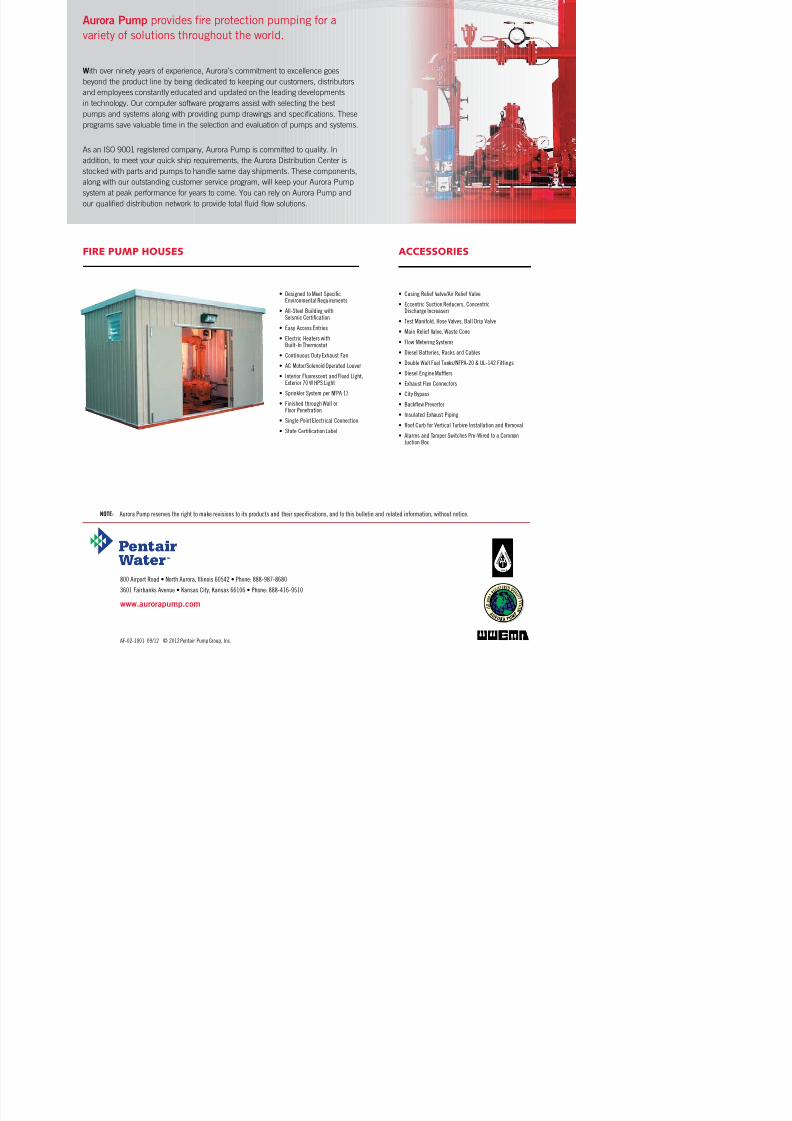
Aurora Pump
provides fire protection pumping for a
7/17/2019 Tech Data 1500 Gpm - For Power Island System Rev.01
http://slidepdf.com/reader/full/tech-data-1500-gpm-for-power-island-system-rev01 23/101
With over ninety years of experience, Aurora’s commitment to excellence goes
beyond the product line by being dedicated to keeping our customers, distributors
and employees constantly educated and updated on the leading developmentsin technology. Our computer software programs assist with selecting the best
pumps and systems along with providing pump drawings and specifications. These
programs save valuable time in the selection and evaluation of pumps and systems.
As an ISO 9001 registered company, Aurora Pump is committed to quality. In
addition, to meet your quick ship requirements, the Aurora Distribution Center is
stocked with parts and pumps to handle same day shipments. These components,
along with our outstanding customer service program, will keep your Aurora Pumpsystem at peak performance for years to come. You can rely on Aurora Pump and
our qualified distribution network to provide total fluid flow solutions.
variety of solutions throughout the world.
ACCESSORIES
• Casing Relief Valve/Air Relief Valve
• Eccentric Suction Reducers, ConcentricDischarge Increasers
• Test Manifold, Hose Valves, Ball Drip Valve
• Main Relief Valve, Waste Cone
• Flow Metering Systems
• Diesel Batteries, Racks and Cables
• Double Wall Fuel Tanks/NFPA-20 & UL-142 Fittings
• Diesel Engine Mufers
• Exhaust Flex Connectors
• City Bypass
• Backow Preverter
• Insulated Exhaust Piping
• Roof Curb for Vertical Turbine Installation and Removal
• Alarms and Tamper Switches Pre-Wired to a Common Juction Box
• Designed to Meet SpecicEnvironmental Requirements
• All-Steel Building withSeismic Certication
• Easy Access Entries
• Electric Heaters withBuilt-In Thermostat
• Continuous Duty Exhaust Fan
• AC Motor/Solenoid Operated Louver
• Interior Fluorescent and Flood Light,Exterior 70 W HPS Light
• Sprinkler System per NFPA 13
• Finished through Wall orFloor Penetration
• Single Point Electrical Connection
• State Certication Label
FIRE PUMP HOUSES
qwertyuiopasdfghjklzxcvbnmqwertyui

7/17/2019 Tech Data 1500 Gpm - For Power Island System Rev.01
http://slidepdf.com/reader/full/tech-data-1500-gpm-for-power-island-system-rev01 24/101
qwertyuiopasdfghjklzxcvbnmqwertyui
opasdfghjklzxcvbnmqwertyuiopasdfgh
jklzxcvbnmqwertyuiopasdfghjklzxcvb
nmqwertyuiopasdfghjklzxcvbnmqwer
tyuiopasdfghjklzxcvbnmqwertyuiopasdfghjklzxcvbnmqwertyuiopasdfghjklzx
cvbnmqwertyuiopasdfghjklzxcvbnmqwertyuiopasdfghjklzxcvbnmqwertyuio
pasdfghjklzxcvbnmqwertyuiopasdfghj
klzxcvbnmqwertyuiopasdfghjklzxcvbn
mqwertyuiopasdfghjklzxcvbnmqwerty
uiopasdfghjklzxcvbnmqwertyuiopasdf
ghjklzxcvbnmqwertyuiopasdfghjklzxc
Spare Part List BookController Model : GPD
PERTAMINA BALIKPAPAN‐DEPOT PANGKALAN BUN,
DEPOT PULANG PISAU, DPPU JUWATA
Prepared by : PT. Roda Nurmala
ELECTRIC FIRE PUMP
Aurora Horizontal Split Case
Model : 6-481-14HH/Single Stage
COAL FIRED POWER STATION,BABELAN
Customer :
Project name : DefaultPump Performance Curve
Encompass 2.0 - 15.3.1.0

7/17/2019 Tech Data 1500 Gpm - For Power Island System Rev.01
http://slidepdf.com/reader/full/tech-data-1500-gpm-for-power-island-system-rev01 25/101
j Encompass 2.0 15.3.1.0
0
50
100
150
200
P o w e r - k W
Power
0
2
4
6
8
10
12
14
16
18
20
0 50 100 150 200 250 300 350 400 450 500 550 600 650
H e a d - b a r
Flow - m3/h
284 mm
49
49
60
60
68
68
73
73
75
75
356 mm
227 mm
Preferred operating region
Item number : 010 Size : 6-481-14HH
Service : Stages : 1
Quantity : 1 Driver type : Motor
O O S
912 231

7/17/2019 Tech Data 1500 Gpm - For Power Island System Rev.01
http://slidepdf.com/reader/full/tech-data-1500-gpm-for-power-island-system-rev01 26/101
AURORA MODEL 481 PUMPS
ON STANDARD STEEL BASE
DISCH MODEL
CASE
BORE
2-1/2 481 10B 3 8 4 13-1/2 9-3/4 4 20 5 10
(203) (102) (343) (247) (102) (609) (127) (254)
3 481 10 4 9* 4-1/2 13-1/2 10 4-1/2 24 5 11
(228) (114) (343) (254) (114) (609) (127) (279)
4 481 10+ 5 14-1/2 11-1/4 5 26 6 12-3/4
(254) (127) (368) (286) (127) (660) (152) (324)
4 481 11D 5 10+ 5 14-1/2 12 5 26 6 12-3/4
(254) (127) (368) (305) (124) (660) (152) (324)
4 481 15 5 11 5-1/2 14-1/2 13 5-1/2 26 6 14
(279) (140) (368) (330) (140) (660) (152) (355)
5 481 11** 5-1/2 16 11-1/4 5-1/2 28-1/2 6 13-1/4
(279) (140) (406) (286) (140) (723) (152) (336)
5 481 15 6 12-1/2 6-1/4 16 13-1/4 6-1/4 26-1/2 6 15
(217) (159) (406) (336) (159) (673) (152) (381)5 481 17 6 12-1/2 6-1/4 16 14 6-1/4 28-1/2 6 15
(217) (159) (406) (355) (159) (723) (152) (381)
6 481 11 8 12-1/2 6-1/4 16 11-3/4 6-1/4 28-1/ 2 6 14-1/ 2
(217) (159) (406) (298) (159) (723) (152) (368)
6 481 11HH 8 16-1/2 8-5/8 18-1/2 1 0 8-5/8 32-7/8 8 15
(419) (219) (460) (254) (219) (835) (203) (381)
6 481 14HH 8 16-1/2 7-1/2 20-1/2 1 5 7-1/2 36-3/4 8 17
(419) (191) (519) (381) (191) (933) (203) (431)
6 481 13-1/2 6-3/4 18 14-1/4 6-3/4 32 7 16-3/4
(343) (171) (457) (368) (171) (812) (178) (425)
6 481 14-3/4 8 18 16 8 32 7 18
(374) (203 (457) (406) (203) (812) (178) (457)
6 481 20 8 14-3/4 8 18 15-3/4 8 32 7 18
(374) (203) (457) (400) (203) (812) (178) (457)8 481 12 10 14-3/4 8 18 17 9 32 7 17-3/4
(374) (203) (457) (431) (228) (812) (178) (450)
8 481 17B 10 14-3/4 8 18 17 8 32 7 17-3/4
(374) (203) (457) (431) (203) (812) (178) (450)
8 481 18-1/2 9-1/2 21-7/8 18 9-1/2 38 11 21
(470) (241) (555) (457) (241) (964) (279) (533)
10 481 15C 12 25 13-1/2 21-7/8 17 13-1/2 38 11 20
(635) (343) (555) (431) (343) (964) (279) (508)
10 481 18 1 2 25 1 3-1/2 21-7/8 18 13-1/2 38 11 22
(635) (343) (555) (457) (343) (964) (279) (558)
10 481 18D 12 25 12-1/4 24-1/4 2 0 12-1/4 43 11-1/2 2 4
(635) (311) (616) (508) (311) (1092) (292) (610)
12 481 18A 14 24 15 25-1/4 18 15 44 11 23
(609) (381 (615) (457) (381) (1117) (279) (584)
PUMP SIZE
BASE
D S W X Z CP HY YY ZZAPPROX
BASE
21
BASE
BASE
23 22 2828 29 30 3018
7A
7
2
1-1/4
2
BASE
38 36 40 40 44 45 49
( 1
1 4 3 )
( 1
2 4 5 )
33 32 35 34
2121A
10
8 481 26 15 25-1/4 20 15 43-7/8 11 25
(660) (381) (641) (508) (381) (1114) (279) (635)24 12
5
6B
15B15C
18B18C
8
8
3
4A
5A
BASE
2
4
1-1/4
BASE
BASE
BASE
11A11C
11B11C
6
5
BASE
BASE
BASE
BASE
BASE
BASE
7
BASE
BASE
BASE
BASE
BASE
BASE
-
7
7
7
5
5
7
7
7
7
7
7
7
9
9
9
9
-
10
10
10
10
7
7
9
9
9
10
10
10
10
11
11
11
11
11
9
9
11
11
11
11
11
11
11
12
12
12
12
12
11
11
11
11
2926
11
11
2625
11
2524 24
11
11
11
11
11
12
OPTIONAL 250# SUCTION AND
DISCHARGE FLANGES
STANDARD 125# SUCTION AND
DISCHARGE FLANGES
OPTIONAL 125# SUCTION
FLANGE, 250# DISCHARGE
FLANGE
MOTOR
FRAME
11
12
12
12
12
12
12
12
12
12
11
11
11
11
11
12
12
12
12
12
10
10
11
11
11
12
12
12
12
12
12
12
12
12
11
11
11
11
11
12
12
12
12
12
12
12
12
12
10
10
11
11
11
12
12
12
12
12
12
12
12
12
11
11
11
11
11
12
12
12
12
12
12
12
12
12
11
11
11
11
11
12
12
12
12
12
12
12
12
12
14
11
11
12
12
12
12
12
12
12
12
12
12
12
12
14
11
11
12
12
12
12
12
12
12
13
13
13
13
13
13
14
14
14
12
12
12
12
12
12
12
12
12
13
13
13
13
13
14
14
14
-
-
15
15
15
15
15
15
15
15
15
15
15
15
15
15
16
16
16
-
-
15
15
15
15
15
15
15
-
-
15
15
15
15
15
16
16
16
16
-
-
15
15
15
15
15
15
15
15
16
15
15
15
15
15
16
16
16
16
-
-
15
15
15
15
15
15
15
-
-
16
16
16
16
16
16
16
16
16
-
-
15
-
-
15
15
15
15
16
16
16
16
16
16
16
16
16
16
16
16
-
-
15
-
-
16
16
16
16
-
-
16
16
16
16
16
16
16
16
17
-
-
15
-
-
15
15
15
15
16
16
16
16
16
16
16
16
16
16
16
17
-
-
-
-
-
16
16
16
16
-
-
16
16
16
16
16
17
17
17
17
16
16
17
17
9 9 9
9 9 9
11 11 11
C
17
7
6B
BASE 17 17 17 17
4 4 9 T S
4 4 9 T
Section 912 Page 231
Date March 22, 2013
Supersedes Section 912 Page 231
Dated July 2012
BASE H A HB HE HG HH HF HP
5 12 38 9 3 1/2 17 20(305) (964) (228) (76) (13) (431) (508)
7 13 42 10 4 5/8 17 24(330) (1066) (254) (101) (15) (431) (609)
9 15 44 12 3-3/8 5/8 19 24
NOTES1. All dimensions are in inches.2. Dimensions may vary ± 3/8".3. Not for construction purposes unless certified.4. Coupling gap may vary 1/8" thru 2-1/16".
AURORA FIRE PUMPS S i 916 P 201

7/17/2019 Tech Data 1500 Gpm - For Power Island System Rev.01
http://slidepdf.com/reader/full/tech-data-1500-gpm-for-power-island-system-rev01 27/101
AURORA FIRE PUMPSSTANDARD FIRE PUMP ACCESSORIES
Section 916 Page 201Date February 2005
Supersedes Section 916 Page 201
Dated May 2004
PIPE SIZE“A”
TAP SIZE
2-1/2-481-10
3-481-10
4-481-114-481-15
5-481-11
5-481-15
5-481-17 1-1/4"
6-481-11
6-481-11HH
6-481-14HH
6-481-15
6-481-186-481-20
8-481-12
8-481-21
10-481-15
10-481-18D
NOTES:1. Dimensions are in inches (mm) and may
vary ± 1/4” (6).
2. Accessories shown are shipped loose for
field installtion.
3. Casing relief valve is to be adjusted to
appropriate pressure upon field installtion
4. Casing relief valve is furnished on electric
motor driven units only.
5. Two stage pumps require both vent taps
piped to air release valve.
6. Suction guage range is 30”-0-150 PSI forsuction pressures up to 75 PSI, or 30”-0-
300 PSI for suction pressures over 75 PSI.
7. Discharge gauge range is 0-300-PSI for
pumps with rated discharge pressures up
to 150 PSI, or 0-600 PSI for pumps with
rated discharge pressures over 150 PSI.
E
D
C
"A" PIPE TAP INCASING DISCHARGE
VALVE INLET SIZE "B"(PIPING BY OTHERS)
CASING RELIEF VALVE
3/4" NPT OUTLET
1/2" PIPING BYOTHERS (SEE NOTE 5)
FLOAT-OPERATEDAIR RELEASE VALVE
1/2" NPT OUTLET
3-1/2" (89) DIA. SUCTION ANDDISCHARGE GAUGES WITH1/4" SHUT-OFF COCKS
CASING RELIEF VALVE
SYSTEM VALVE
G.P.M.INLET “C”
SIZE - “B”
250
500
750
Section 916 Page 206 AURORA FIRE PUMPS

7/17/2019 Tech Data 1500 Gpm - For Power Island System Rev.01
http://slidepdf.com/reader/full/tech-data-1500-gpm-for-power-island-system-rev01 28/101
Section 916 Page 206Date June 2002
Supersedes Section 916 Page 206
Dated July 2001
AURORA FIRE PUMPSAUTOMATIC AIR RELEASE VALVE
1/2 NPT" OUTLET 4-3/4 (121)
5-1/4(133)
1/2" NPT INLET
HYDR8AC
(VAL-MATIC VM15A)
OR APPROVED EQUAL USED
WITH HORIZONTAL FIRE PUMPS
WORKING PRESSURE UP TO 300 PSI
(FM APPROVED)
9-1/2 (241)
2" NPT OUTLET
12
(305)
Project:

7/17/2019 Tech Data 1500 Gpm - For Power Island System Rev.01
http://slidepdf.com/reader/full/tech-data-1500-gpm-for-power-island-system-rev01 29/101
Contents:
Model GPY
Project:
Customer:
Engineer:
Pump Manufacturer:

7/17/2019 Tech Data 1500 Gpm - For Power Island System Rev.01
http://slidepdf.com/reader/full/tech-data-1500-gpm-for-power-island-system-rev01 30/101
Submittal Data SheetModel GPY Electric Fire Pump Controller
FM GlobalNew York City
CE Mark
NEMA 12 NEMA 4X 304 sst painted IP54
Accepted for use in the City of New York by the Department of Buildings
Built to NFPA 20 (latest edition)
Optional
Standard, Listings,
Approvals and
Certifications
Underwriters Laboratory (UL) UL218 - Fire pump controllers CSA C22.2 No. 14 Industrial Control EquipmentClass 1321/1323
Various EN, IEC & CEE directives and standards
Protection Rating
Standard: NEMA 2 (IP31)Optional
Optional 150,000 A 100,000 A
Shortcircuit Withstand
Rating
208V to 480V - 3ph - 50/60Hz 600V - 3ph - 60Hz
Standard 100,000 A 50,000 A
Acr oss-t he line st ar t ing
Locked rotor current
Full load current
Percent of motor speed (%)
L i n e c u r r e
n t
% o
f f u l l l o a d
20 40 60 80 100
600
Transition current
Wye delta starting
Open transition
210
Starting Method: Reduced Voltage
Wye-delta open
Typical Voltage Applied at Start: 100%Inrush Current: 33% of normal load current
Starting Torque: 33%
Motor Type: Wye-delta
No. of Contactors: 2 at 58%, 1 at 33% of motor FLC
Min. ampacity of motor conductors: 6 at 125% x 58% of FLC
T2
T1
T31M
T4
T6
T52M
1S
3L2
1M
CR4
2M
CR5
1S
CR5 2M
1S
3L1
3L2
3L3
3L1
M
From normal
incoming power through
Disconnecting Means
(IS/CB)*

7/17/2019 Tech Data 1500 Gpm - For Power Island System Rev.01
http://slidepdf.com/reader/full/tech-data-1500-gpm-for-power-island-system-rev01 31/101
Submittal Data SheetModel GPY Electric Fire Pump Controller
Surge
Suppression
Service
Entrance
Rating
Door interlocked in the ON position
EmergencyStart Handle Integrated limit switch
Across the line start (direct on line)
Flange mounted
Operate shunt trip to open circuit breaker Factory set at 600% of motor full load current
Voltage phase to phase (normal power) Amperage of each phase when motor is running
Pressure
Sensing Drain connection 3/8"
Pressure transducer and run test solenoid valve assembly for fresh water application
Pressure sensing line connection 1/2Ž Female NPT
Rated for 0-500PSI working pressure (calibrated at 0-300psi) Externally mounted with protective cover
Under regular maintained operation, events can be stored in memory for up to 5 years.Data viewable on operator interface display screen
Surge arrestor rated to suppress surges above line voltage
Isolating switch and circuit breaker assembly:
Isolating switch rated not less than 115% of motor full load current
Circuit breaker continuous rating not less than 115% of motor full load currentOvercurrent sensing non-thermal type, magnetic onlyInstantaneous trip setting of not more than 20 times the motor full load current
Common flange mounted operating handle
Trip between 8 and 20 seconds
Downloadable by USB port to external memory device
Continuous system pressure display Cut-in and Cut-out pressure settings
Pressure readings with date stamp Event recording with date stamp
PressureReadings
Pressure and
Event
Recorder
Disconnecting
Means
Suitable as service entrance equipment
Pull and latch activation
Locked Rotor
Protector
Electrical
Readings

7/17/2019 Tech Data 1500 Gpm - For Power Island System Rev.01
http://slidepdf.com/reader/full/tech-data-1500-gpm-for-power-island-system-rev01 32/101
Submittal Data SheetModel GPY Electric Fire Pump Controller
Audible Alarm
Power available Locked rotor Manual start Phase reversal Periodic test Deluge valve startMotor run Fail to start Remote automatic startPump room alarm Low discharge pressure Remote manual startMotor trouble Low pump room temperature Overcurrent
Phase loss Pump room temperature (ºF or ºC) Undercurrent Phase unbalance Pump on demand/Automatic start Undervoltage Low w ater level Emergency start Overvoltage
Overvoltage Undervoltage Phase unbalance Low pump room temperature temperature
Overcurrent Fail to start Undercurrent Ground fault
Expandable storage Multi-language
Sequential start timer (on delay) Periodic test timer PressureNon-pressure Automatic
Actuation
Start on pressure drop
Manual Start
Start pushbutton Run test pushbutton Deluge valve start
Timers
Remote start from manual device
Field Adjustable & Visual Countdown
Visual IndicationMode
Manual with Stop pushbutton
Remote start signal from automatic deviceAutomatic Start
Embedded microcomputer with software PLC logic 4.2Ž color touch screen (HMI technology) Upgradable software
StoppingAutomatic after expiration of minimum run timer **
ViZiTouch
Operator
Interface
Visual
Indications and
Alarms
Operation
Common motor trouble
Remote AlarmContacts
SPDT-8A-250V.AC Power available
4Ž alarm bell - 85 dB at 10ft. (3m)
Phase reversal
Common pump room alarm
Motor run

7/17/2019 Tech Data 1500 Gpm - For Power Island System Rev.01
http://slidepdf.com/reader/full/tech-data-1500-gpm-for-power-island-system-rev01 33/101
Submittal Data SheetModel GPY Electric Fire Pump Controller
D1Low suction pressure transducer for fresh waterrated at 0-300PSI with visual indication and alarmcontact
D1ALow suction pressure transducer for sea waterrated at 0-300PSI with visual indication and alarmcontact
D5
Pressure transducer and run test solenoid valve
for fresh water rated for 0-500PSI (for calibrationpurposes only)
D5DPressure transducer and run test solenoid valvefor sea water rated for 0-500PSI
D10 Omit mounting feet (when applicable)
D13High withstand rating (fire pump section only) upto 480V = 150KA / 600V = 100KA
D14Anti-condensation heater & thermostat(fire pump section only)
D14AAnti-condensation heater & humidistat(fire pump section only)
D14BAnti-condensation heater & thermostat &humidistat (fire pump section only)
D15 TropicalizationD18 CE Mark with factory certificateD19 French labelingD20 Spanish labelingD21 Other languagesD26 Modbus RTU provisionD26A Modbus TCP/IP provision
D27Motor heater connection (external single phasepower source and heater on/off contact)
D27AMotor heater connection (internal s ingle phasepower source and heater on/off contact)
D28 Customized drawing setD34 Field programmable I/O board - 8 Input / 5 outputD35 Field programmable I/O board - 8 Input / 10 output
D36Redundant pressure transducer for fresh waterrated for 0-500PSI (calibrated at 0-300PSI)
D36ARedundant pressure transducer for sea waterrated for 0-500PSI (calibrated at 0-300PSI)
D37 Window kit for operator interface
Note: Options chosen from this page are not electricallyrepresented on the wiring schematics in this submittalpackage.
A4 Flow switch provision
A8Foam pump application w/o pressure transducerand run test solenoid valve
A9 Low zone pump control functionA10 Medium zone pump control functionA11 High zone pump control function
A13
Non-pressure actuated controller w/o pressure
transducer and run test solenoid valve
A16Lockout/interlock circuit from equipment installedinside the pump roomBuilt in alarm panel (120V.AC supervisory power)providing indication for:
Audible alarm & silence pushbutton for motorrun, phase reversal, loss of phase.
Pilot lights for loss of phase & supervisorypower available
B11BBuilt in alarm panel same as B11 but
220-240VAC supervisory power
B19High motor temperature thermistor relay c/wvisual indication and alarm contact(Form C-SPDT)
B21Ground fault alarm detection c/w visual indicationand alarm contact (Form C-SPDT)
C1 Extra motor run alarm contact (Form C-SPDT)C4 Periodic test alarm contact (Form C-SPDT)
C6Low discharge pressure alarm contact(Form C-SPDT)
C7 Low pump room temperature alarm contact(Form C-SPDT)
C10High water reservoir level alarm contact(Form C-SPDT)
C11High electric motor temperature alarm contact(Form C-SPDT)
C12High electric motor vibration c/w visual indicationand alarm contact (Form C-SPDT)
C14Pump on demand/automatic start alarm contact(Form C-SPDT)
C15 Pump fail to start alarm contact (Form C-SPDT)
C16 Control voltage healthy alarm contact(Form C-SPDT)
C17Flow meter valve loop open c/w visual indicationand alarm contact (Form C-SPDT)
C18High water reservoir level c/w visual indicationand alarm contact (Form C-SPDT)
C19 Emergency start alarm contact (Form C SPDT)
B11

7/17/2019 Tech Data 1500 Gpm - For Power Island System Rev.01
http://slidepdf.com/reader/full/tech-data-1500-gpm-for-power-island-system-rev01 34/101
Submittal Data SheetModel GPY Electric Fire Pump Controller
ViZiTouch Operator Interface
??
4
9
11 12
10
13
5 6 7
3
2
1
8
8
1 - Power LED 8 - USB port

7/17/2019 Tech Data 1500 Gpm - For Power Island System Rev.01
http://slidepdf.com/reader/full/tech-data-1500-gpm-for-power-island-system-rev01 35/101
7/17/2019 Tech Data 1500 Gpm - For Power Island System Rev.01
http://slidepdf.com/reader/full/tech-data-1500-gpm-for-power-island-system-rev01 36/101

7/17/2019 Tech Data 1500 Gpm - For Power Island System Rev.01
http://slidepdf.com/reader/full/tech-data-1500-gpm-for-power-island-system-rev01 37/101

7/17/2019 Tech Data 1500 Gpm - For Power Island System Rev.01
http://slidepdf.com/reader/full/tech-data-1500-gpm-for-power-island-system-rev01 38/101

7/17/2019 Tech Data 1500 Gpm - For Power Island System Rev.01
http://slidepdf.com/reader/full/tech-data-1500-gpm-for-power-island-system-rev01 39/101
qwertyuiopasdfghjklzxcvbnmqwertyui

7/17/2019 Tech Data 1500 Gpm - For Power Island System Rev.01
http://slidepdf.com/reader/full/tech-data-1500-gpm-for-power-island-system-rev01 40/101
opasdfghjklzxcvbnmqwertyuiopasdfgh
jklzxcvbnmqwertyuiopasdfghjklzxcvbnmqwertyuiopasdfghjklzxcvbnmqwer
tyuiopasdfghjklzxcvbnmqwertyuiopasdfghjklzxcvbnmqwertyuiopasdfghjklzx
cvbnmqwertyuiopasdfghjklzxcvbnmqwertyuiopasdfghjklzxcvbnmqwertyuio
pasdfghjklzxcvbnmqwertyuiopasdfghj
klzxcvbnmqwertyuiopasdfghjklzxcvbn
mqwertyuiopasdfghjklzxcvbnmqwerty
uiopasdfghjklzxcvbnmqwertyuiopasdf
ghjklzxcvbnmqwertyuiopasdfghjklzxc
Spare Part List BookController Model : GPD
PERTAMINA BALIKPAPAN‐DEPOT PANGKALAN BUN,
DEPOT PULANG PISAU, DPPU JUWATA
Prepared by : PT. Roda Nurmala
DIESEL FIRE PUMP
Aurora Horizontal Split Case
Model : 6-481-14HH/Single Stage
COAL FIRED POWER STATION,BABELAN
Customer :
Project name : DefaultPump Performance Curve
Encompass 2.0 - 15.3.1.0
DFP.Cap.1500 Gpm @ 150 Psi Total Head

7/17/2019 Tech Data 1500 Gpm - For Power Island System Rev.01
http://slidepdf.com/reader/full/tech-data-1500-gpm-for-power-island-system-rev01 41/101
0
50
100
150
200
P o w e r - k W
Power
0
25
50
75
100
125
150
175
200
225
250
0 50 100 150 200 250 300 350 400 450 500 550 600
H e a d - p s i
Flow - m3/h
314 mm
51
51
63
63
72
72
77
77
81
356 mm
223 mm
Preferred operating region
Item number : 010 Size : 6-481-14HH
Service : Stages : 1
Quantity : 1 Driver type : Engine
p p @
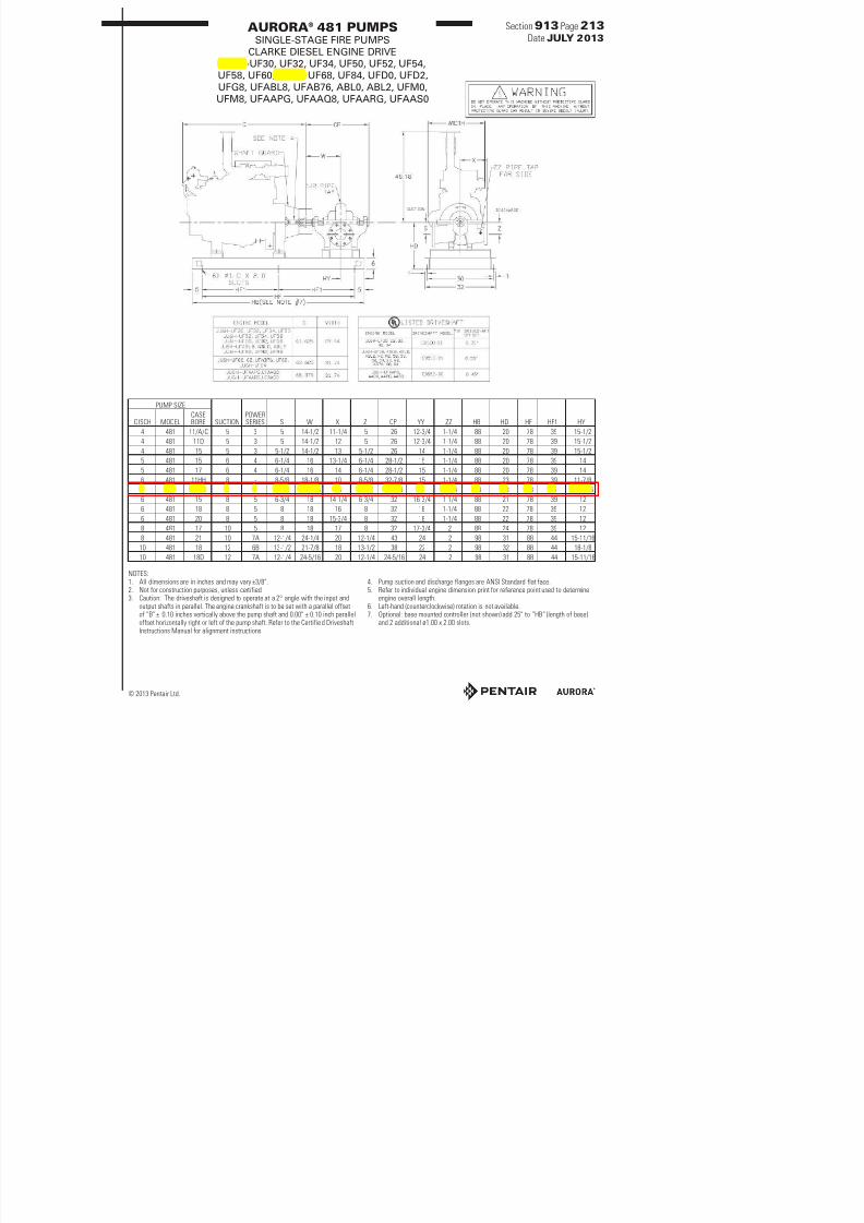
AURORA® 481 PUMPSSINGLE-STAGE FIRE PUMPS
CLARKE DIESEL ENGINE DRIVE
Section 913 Page 213
Date JULY 2013
7/17/2019 Tech Data 1500 Gpm - For Power Island System Rev.01
http://slidepdf.com/reader/full/tech-data-1500-gpm-for-power-island-system-rev01 42/101
JU6H-UF30, UF32, UF34, UF50, UF52, UF54,
UF58, UF60, UF62, UF68, UF84, UFD0, UFD2,
UFG8, UFABL8, UFAB76, ABL0, ABL2, UFM0,
UFM8, UFAAPG, UFAAQ8, UFAARG, UFAAS0
PUMP SIZE
SUCTIONPOWERSERIES S W X Z CP YY ZZ HB HD HF HF1 HYDISCH MODEL
CASEBORE
4 481 11/A/C 5 3 5 14-1/2 11-1/4 5 26 12-3/4 1-1/4 88 20 78 39 15-1/2
4 481 11D 5 3 5 14-1/2 12 5 26 12-3/4 1-1/4 88 20 78 39 15-1/2
4 481 15 5 3 5-1/2 14-1/2 13 5-1/2 26 14 1-1/4 88 20 78 39 15-1/2
5 481 15 6 4 6-1/4 16 13-1/4 6-1/4 28-1/2 15 1-1/4 88 20 78 39 14
5 481 17 6 4 6-1/4 16 14 6-1/4 28-1/2 15 1-1/4 88 20 78 39 14
6 481 11HH 8 - 8-5/8 18-1/8 10 8-5/8 32-7/8 15 1-1/4 88 23 78 39 11-7/8
6 481 14HH 8 - 7-1/2 20-7/16 15 7-1/2 36-3/4 17 1-1/4 98 23 88 44 19-9/16
6 481 15 8 5 6-3/4 18 14-1/4 6-3/4 32 16-3/4 1-1/4 88 21 78 39 12
6 481 18 8 5 8 18 16 8 32 18 1-1/4 88 22 78 39 12
6 481 20 8 5 8 18 15-3/4 8 32 18 1-1/4 88 22 78 39 12
8 481 17 10 5 8 18 17 8 32 17-3/4 2 88 24 78 39 12
8 481 21 10 7A 12-1/4 24-1/4 20 12-1/4 43 24 2 98 31 88 44 15-11/16
10 481 18 12 6B 13-1/2 21-7/8 18 13-1/2 38 22 2 98 32 88 44 18-1/8
D A / / / / 3 /
PRELIMINARY ONLY

7/17/2019 Tech Data 1500 Gpm - For Power Island System Rev.01
http://slidepdf.com/reader/full/tech-data-1500-gpm-for-power-island-system-rev01 43/101
PT. RODA NURMALA
Project
Checked
Approved
Drawn
Scale
Dwg. No :
UNSCALE
AY
STANDAR INSTALASI NFPA DIESEL, E LEC TRIC & JOC KEY FIRE PUMP
Single Line Pi ppe Drawing
RN-DK0031300810
RZ
This Draw Property of PT. Roda Nurmala, Shall be use for Corporate purpose. if this draw not used again, so expected to deleted this drawn.
NOTE :
This Draw just prelim inary only for describe the real condition.
NFPA 20 Piping & Accessories Standard Information
1500 GPM FIRE PUMP Jockey Pum p 12 M
Suction Pipe
Discharge Pipe
Relief Valve
Waste Cone
Metering Device
Suction Gate Valve
Suction Pipe
Discharge Pipe
Suction Gate Valve
8"
8"
6" x 6"
6" x 8"
8"
OS & Y Valve
OS
FW
COAL FIRED STATION B
FIRE PUMP ENGINES
MODELSJU6H-UFD0 JU6H-UF34 JU6H-UFABL2 JU6H-UF58 JU6H-UFAB76 JU6H-UFAAQ8
JU6H-UFD2 JU6H-UFG8 JU6G-UFM8 JU6H-UF50 JU6H-UF68 JU6H-UFAAPG
JU6H-UF30 JU6H-UFABL8 JU6H-UFM0 JU6H-UF52 JU6H-UF60 JU6H-UFAARG
JU6H UF32 JU6H UFABL0 JU6H UFM2 JU6H UF54 JU6H UF62 JU6H UF84
®
JU6H UFAAS0

7/17/2019 Tech Data 1500 Gpm - For Power Island System Rev.01
http://slidepdf.com/reader/full/tech-data-1500-gpm-for-power-island-system-rev01 44/101
FM-UL-cUL APPROVED RATINGS BHP/KW
JU6H-UF32 JU6H-UFABL0 JU6H-UFM2 JU6H-UF54 JU6H-UF62 JU6H-UF84 JU6H-UFAAS0
JU6HMODEL
RATED SPEED US-EPA
(NSPS)Available
Until1470 1760 2100 2350 2600 2800 3000
UFD0 110 82 144 107 148 110 12/31/09
UFD2 148 110 148 110 12/31/09
UF30 94 70 140 104 160 119 160 119 12/31/09
UF32 160 119 160 119 12/31/09
UF34 160 119 175 13112/31/11▲
12/31/12▼+
UFG8 130 97 149 111 12/31/09
UFABL8 136 101 173 129 12/31/09
UFABL0 173 129 173 129 173 129 12/31/09
UFABL2 173 129 173 129 12/31/09
UFM8 136 101 175 131 12/31/09
UFM0 175 131 207 154 200 149 12/31/08
UFM2 200 149 200 149 12/31/08
UF58 138 103 183 137 12/31/08
UF50 183 137 210 157 210 157 12/31/08
UF68 175 131 200 149 12/31/08
UF52 210 157 210 157 12/31/08
UF54 216 161 216 161 12/31/11
UFAAPG 220 164 N/A
UFAB76 225 168 12/31/11
UFAAQ8 227 169 N/A
UF60 200 149 240 179 240 179 12/31/08
UF62 240 179 240 179 12/31/08
UFAARG 252 188 N/A
USA EPA (NSPS) Emissions Compliant. Applies to John
Deere model year per Table 4 of 40 CFR Part 60 Sub PartIIII.
All Models are available for Export
N/A = Not Applicable / Non-Emissionized
+ Not Available in California
UF84 259 193 275 205 12/31/11
UFAAS0 260 194 N/A
SPECIFICATIONS
ITEMJU6H MODELS
D0 D2 30 32 34 G8 ABL8 ABL0 ABL2 M8 M0 M2 58 50 52 54 AB76 68 60 62 AAQ8 PG AARG/S0 84
Number of Cylinders 6
Asp irat ion T TRWA
Rotation* CW
–
▼
▲Greater than 174 HP
–
Compression Ratio 17.0:1
Displacement – cu. in. (L) 414 (6.8)
Engine Type 4 Stroke Cycle – Inline Construction
Bore & Stroke – in. (mm) 4.19 x 5.00 (106 x 127)Installation Drawing D536
Wiring Diagram AC C07591
Wiring Diagram DC C071590
Speed Interpolation OPT.
FIRE PUMP ENGINES
MODELS ®
JU6H-UFD0 JU6H-UF34 JU6H-UFABL2 JU6H-UF58 JU6H-UFAB76 JU6H-UFAAQ8
JU6H-UFD2 JU6H-UFG8 JU6G-UFM8 JU6H-UF50 JU6H-UF68 JU6H-UFAAPG
JU6H-UF30 JU6H-UFABL8 JU6H-UFM0 JU6H-UF52 JU6H-UF60 JU6H-UFAARG
JU6H-UF32 JU6H-UFABL0 JU6H-UFM2 JU6H-UF54 JU6H-UF62 JU6H-UF84 JU6H-UFAAS0

7/17/2019 Tech Data 1500 Gpm - For Power Island System Rev.01
http://slidepdf.com/reader/full/tech-data-1500-gpm-for-power-island-system-rev01 45/101
ENGINE EQUIPMENT
JU6H UF32 JU6H UFABL0 JU6H UFM2 JU6H UF54 JU6H UF62 JU6H UF84
EQUIPMENT STANDARD OPTIONAL
Air Cleaner Direct Mounted, Washable, Indoor Service with Drip Shield Disposable, Drip Proof, Indoor Service Outdoor Type
Alt ernat or 12V-DC, 42 Amps with Poly-Vee Belt and Guard 24V-DC, 40 Amps with Poly-Vee Belt and Guard
Exhaust Protection Metal Guards on Manifolds and Turbocharger
Coupling Bare Flywheel Listed Driveshaft and Guard, UFD0/D2/30/32/34 –CDS20-S1;
UFG8/ABL8/ABL0/ABL2/M8/M0/M2/58/50/52/54/AB76/68/60/62/AA
Q8/AARG/AAPG/84/S0 –CDS30-S1
Exhaust Flex Connection Stainless Steel Flex, 150# ANSI Flanged Connection, 5” Stainless Steel Flex, 150# ANSI Flanged Connection, 6”
Flywheel Housing SAE #3
Flywheel Power Take Off 11.5” SAE Industrial Flywheel Connection
Fuel Connections Fire Resistant, Flexible, USA Coast Guard Approved, Supply andReturn Lines
Stainless Steel, Braided, cUL Listed, Supply and Return Lines
Fuel Filter Primary Filter with Priming Pump
Fuel Injection System Stanadyne Direct Injection
Engine Heater 120V-AC, 1500 Watt 240V-AC, 1500 Watt
Governor, Speed Constant Speed, Mechanical
Heat Exchanger Tube and Shell Type, 60 PSI (4 BAR), NPT(F) Connections
Instrument Panel English and Metric, Tachometer, Hourmeter, Water Temperature,
Oil Pressure and Two (2) Voltmeters
Junction Box Integral with Instrument Panel; For DC Wiring Interconnection to
Engine Controller
Lube Oil Cooler Engine Water Cooled, Plate Type
Lube Oil Filter Full Flow with By-Pass Valve
Lube Oil Pump Gear Driven, Gear Type
Overspeed Control Electronic with Reset and Test on Instrument Panel
Raw Water Solenoid Operation Automatic from Fire Pump Controller and from Engine Instrument
Panel
Run – Stop Control On Instrument Panel with Control Position Warning Light
Run Solenoid 12V-DC Energized to Run 12V-DC Energized to Stop; 24V-DC Energized to Run; 24V-DC
Energized to Stop
Starters Two (2) 12V-DC Two (2) 24V-DC
Adustable S eed Control Tam er Proof,
Water Pump Centrifugal Type, Poly-Vee Belt Drive with Guard
Abbreviations :DC –Direct Current, AC –Alternating Current, SAE –Society of Automotive Engineers, NPT(F) –National Pipe Tapered Thread (Female)

7/17/2019 Tech Data 1500 Gpm - For Power Island System Rev.01
http://slidepdf.com/reader/full/tech-data-1500-gpm-for-power-island-system-rev01 46/101
JU6H-UF62
INSTALLATION & OPERATION DATA (I&O Data)

7/17/2019 Tech Data 1500 Gpm - For Power Island System Rev.01
http://slidepdf.com/reader/full/tech-data-1500-gpm-for-power-island-system-rev01 47/101
USA Produced
( )
Basic Engine Description
Engine Manufacturer John Deere Co.
Ignition Type Compression (Diesel)
Number of Cylinders 6
Bore and Stroke - in (mm) 4.19 (106) X 5 (127)
Displacement - in³ (L) 415 (6.8)
Compression Ratio 17.0:1
Valves per cylinderIntake 1
Exhaust 1
Combustion System Direct Injection
Engine Type In-Line, 4 Stroke Cycle
Fuel Management Control Mechanical, Rotary Pump
Firing Order (CW Rotation) 1-5-3-6-2-4Aspiration Turbocharged
Charge Air Cooling Type Raw Water
Rotation, viewed from front of engine, Clockwise (CW) Standard
Engine Crankcase Vent System Open
Installation Drawing D536
Weight - lb (kg) 1693 (768)
Power Rating 2350 2600
Nameplate Power - HP (kW) 240 (179) 240 (179)
Cooling System - [C051127] 2350 2600Engine Coolant Heat - Btu/sec (kW) 101 (107) 118 (125)
Engine Radiated Heat - Btu/sec (kW) 54 (57) 54 (57)
Heat Exchanger Minimum Flow60°F (15°C) Raw H20 - gal/min (L/min) 23 (87.1) 25 (94.6)
95°F (35°C) Raw H20 - gal/min (L/min) 25 (94.6) 26 (98.4)
Heat Exchanger Maximum Cooling Raw WaterInlet Pressure - psi (bar) 60 (4.1)
Flow - gal/min (L/min) 40 (151)
Typical Engine H20 Operating Temp - °F (°C) 180 (82.2) - 195 (90.6)
ThermostatStart to Open - °F (°C) 187 (86.1)
Fully Opened - °F (°C) 196 (91.1)
Engine Coolant Capacity - qt (L) 14.79 (14)
Coolant Pressure Cap - lb/in² (kPa) 10 (68.9)
Maximum Engine Coolant Temperature - °F (°C) 200 (93.3)
Minimum Engine Coolant Temperature - °F (°C) 160 (71.1)
High Coolant Temp Alarm Switch - °F (°C) 205 (96.1)
Electric System - DC Standard Optional
System Voltage (Nominal) 12 24
Battery Capacity for Ambients Above 32°F (0°C)Voltage (Nominal) 12 [C07633] 24 [C07633]
Qty. Per Battery Bank 1 2
SAE size per J537 8D 8D
CCA @ 0°F (-18°C) 1400 1400
Reserve Capacity - Minutes 430 430
Battery Cable Circuit, Max Resistance - ohm 0.0012 0.0012
C
JU6H-UF62
INSTALLATION & OPERATION DATA (I&O Data)

7/17/2019 Tech Data 1500 Gpm - For Power Island System Rev.01
http://slidepdf.com/reader/full/tech-data-1500-gpm-for-power-island-system-rev01 48/101
USA Produced
Exhaust System 2350 2600
Exhaust Flow - ft.³/min (m³/min) 1345 (38.1) 1484 (42)
Exhaust Temperature - °F (°C) 883 (473) 898 (481)
Maximum Allowable Back Pressure - in H20 (kPa) 30 (7.5) 30 (7.5)
Minimum Exhaust Pipe Dia. - in (mm)[3] 5 (127) 5 (127)
Fuel System 2350 2600
Fuel Consumption - gal/hr (L/hr) 11.2 (42.4) 12.7 (48.1)
Fuel Return - gal/hr (L/hr) 7 (26.5) 8.6 (32.6)
Fuel Supply - gal/hr (L/hr) 18.2 (68.9) 21.3 (80.6)
Fuel Pressure - lb/in² (kPa) 4 (27.6) - 6 (41.4)
Minimum Line Size - Supply - in. .50 Schedule 40 Steel Pipe
Pipe Outer Diameter - in (mm) 0.848 (21.5)
Minimum Line Size - Return - in. .375 Schedule 40 Steel PipePipe Outer Diameter - in (mm) 0.675 (17.1)
Maximum Allowable Fuel Pump Suction Liftwith clean Filter - in H20 (mH20) 31 (0.8)
Maximum Allowable Fuel Head above Fuel pump, Supply or Return - ft (m) 4.5 (1.4)
Fuel Filter Micron Size 5
Heater System Standard Optional
Engine Coolant Heater
Wattage (Nominal) 1500 1500
Voltage - AC, 1 Phase 120 (+5%, -10%) 240 (+5%, -10%)
Part Number [C124948] [C124949]
Air System 2350 2600
Combustion Air Flow - ft.³/min (m³/min) 538 (15.2) 587 (16.6)
Air Cleaner Standard Optional
Part Number [C03396] [C03327]
Type Indoor Service Only, with Shield Canister, Single-Stage
Cleaning method Washable Disposable
Air Intake Restriction Maximum LimitDirty Air Cleaner - in H20 (kPa) 12 (3) 10 (2.5)
Clean Air Cleaner - in H20 (kPa) 6 (1.5) 5 (1.2)
Maximum Allowable Temperature (Air To Engine Inlet) - °F (°C)[4] 130 (54.4)
Lubrication System
Oil Pressure - normal - lb/in² (kPa) 40 (276) - 60 (414)
Low Oil Pressure Alarm Switch - lb/in² (kPa) 20 (138)
In Pan Oil Temperature - °F (°C) 220 (104) - 245 (118)
Total Oil Capacity with Filter - qt (L) 21.1 (20)
Lube Oil Heater Optional Optional
Wattage (Nominal) 150 150
Voltage 120V (+5%, -10%) 240V (+5%, -10%)
Part Number C04430 C04431
Performance 2350 2600
BMEP - lb/in² (kPa) 195 (1340) 176 (1210)
Piston Speed - ft/min (m/min) 1958 (597) 2167 (661)
Mechanical Noise - dB(A) @ 1m C131783
CLARKEFire Protection Products
JU4H & JU6H ENGINE MODELS
ENGINE MATERIALS AND CONSTRUCTION

7/17/2019 Tech Data 1500 Gpm - For Power Island System Rev.01
http://slidepdf.com/reader/full/tech-data-1500-gpm-for-power-island-system-rev01 49/101
Air Cleaner Valves
Type…………..………….. .. Indoor Usage Only Type…….. ……………… Poppet
Oiled Fabric Pleats Arrangement………… … Overhead Valve
Material……..…..…….…… Surgical Cotton Number/Cylinder………… 1 intake Aluminum Mesh 1 exhaust
Operating Mechanism… Mechanical Rocker Arm
Air Cleaner - Optional Type of Lifter…………….. Large Head
Type…………………………Canister Valve Seat Insert…………Replaceable
Material…………………… Pleated Paper
Housing………………..……Enclosed Fuel Pump
Type…… ……………… Diaphragm
Camshaft Drive……………………… Cam Lobe
Material………….………….Cast Iron
Chill Hardened Heat Exchanger (USA)
Location…………...….…….In Block Type……………………… Tube & Shell
Drive……………….………..Gear, Spur Materials
Type of Cam…………..…... Ground Tube& Headers………… Copper
Shell…… ……………… Copper
Electrode………………… Zinc
Type………………….Raw Water Cooled
Heat Exchanger (UK)
Materials (in contact with raw water) Type……………………… Tube & Bundle
Tubes…… ………………… 90/10 CU/NI Materials
Headers ………………… 36500 Muntz Tube& Headers………… Copper
Covers ………………… 83600 Red Brass Shell………………. Aluminum
Plumbing ………………… 316 Stainless Steel/ Brass
90/10 Silicone
Coolant Pump Injection Pump
Type…… .…………………Centrifugal Type………………………. Rotary
Drive…… ……… ……… Poly Vee Belt Drive……………………… Gear
Coolant Thermostat Lubrication CoolerType…………………………Non Blocking Type……………………… Plate
Qty………………………… 1
Lubrication Pump
Connecting Rod Type……………………… Gear
Type…………………………I-Beam Taper Drive……………………… Gear
Material…………………… Forged Steel Alloy
Crank Pin Bearings Main Bearings
Type…………………………Precision Half Shell Type……………………… Precision Half Shells
Number…………………… 1 Pair Per Cylinder Material……………………Steel Backed-Aluminum LinedMaterial…………………… Wear-Guard
Crankshaft Piston
Material…………………… Forged Steel Type and Material……… Aluminum Alloy with Reinforced
Type of Balance……………Dynamic Top Ring Groove
C li Oil J t S
Charge Air Cooler (JU6H-60,62,68,74,84, ADK0,
AD58, ADNG, ADN0, ADQ0, ADR0, AAQ8, AARG,
ADP8, ADP0, ADT0, AD88, ADR8, AD98, ADS0,
ADW8, ADX8, AD98 only)

7/17/2019 Tech Data 1500 Gpm - For Power Island System Rev.01
http://slidepdf.com/reader/full/tech-data-1500-gpm-for-power-island-system-rev01 50/101

7/17/2019 Tech Data 1500 Gpm - For Power Island System Rev.01
http://slidepdf.com/reader/full/tech-data-1500-gpm-for-power-island-system-rev01 51/101
JU6H UF62

7/17/2019 Tech Data 1500 Gpm - For Power Island System Rev.01
http://slidepdf.com/reader/full/tech-data-1500-gpm-for-power-island-system-rev01 52/101
6 Cylinders
Four Cycle
Lean Burn
Turbocharged & Raw Water Aftercoole
2350 240 11.2 (42) 0.22 2.88 0.59 0.22 883 (473) 1345 (38)
2600 240 12.7 (48) 0.26 2.76 0.80 0.30 898 (481) 1484 (42)
Notes:
1)
2)
3)
4) PM is a measure of total particulate matter, including PM 10 .
by John Deere Corporation. A copy of the John Deere Emission Warranty can
be found in the Clarke Operation and Maintenance Manual.
Engines are rated at standard conditions of 29.61in. (7521 mm) Hg barometer
and 77°F (25°C) inlet air temperature. (SAE J1349)
FUEL
GAL/HR
(L/HR)
6068HF120 Base Engine Model manufactured by John Deere Corporation.
For John Deere Emissions Conformance to EPA 40 CFR Part 60 see Page 2 of 2.
The Emission Warranty for this engine is provided directly to the owner
500 PPM SULFUR #2 DIESEL FUEL
JU6H-UF62
Stationary Fire Pump Engine Driver
EMISSION DATAEPA 40 CFR Part 60
EXHAUSTRPM BHP (3)
GRAMS / HP- HR
PM (4)NMHC CONOx °F (°C)CFM
m3/min
John Deere Power Systems3801 W. Ridgeway Ave., PO Box 5100Waterloo, Iowa USA 50704-5100

7/17/2019 Tech Data 1500 Gpm - For Power Island System Rev.01
http://slidepdf.com/reader/full/tech-data-1500-gpm-for-power-island-system-rev01 53/101
31 October 2007
Subject: Fire Pump Ratings – Conformance to EPA 40 CFR Part 60 (NSPS requirements)
All John Deere stationary fire pump engines conform to the requirements of 40 CFR Part 60. All suchengines include an emission label, stating the engine conforms to the requirements of 40 CFR Part 60. Anexample of the emission label is show below:
This label applies to all of the following engine models, sold to Clarke Fire Protection, for use in stationaryfire pump applications:

7/17/2019 Tech Data 1500 Gpm - For Power Island System Rev.01
http://slidepdf.com/reader/full/tech-data-1500-gpm-for-power-island-system-rev01 54/101
CLARKECLARKECLARKECLARKEwww.clarkefire.com
RPM BHP OVERALL 31.5 Hz 63 Hz 125 Hz 250 Hz 500 Hz 1k Hz 2k Hz 4k Hz 8k Hz 16k Hz
dB(A) dB(A) dB(A) dB(A) dB(A) dB(A) dB(A) dB(A) dB(A) dB(A) dB(A)
2350 240 106.8 66.3 68.1 80.7 85.8 92.5 98.6 101.6 100.2 93.0 86.6
2600 240 107.8 66.5 67.8 83.6 87.8 93.1 98.0 101.8 100.7 94.5 86.3
RPM BHP OVERALL 31.5 Hz 63 Hz 125 Hz 250 Hz 500 Hz 1k Hz 2k Hz 4k Hz 8k Hz 16k Hz
dB(A) dB(A) dB(A) dB(A) dB(A) dB(A) dB(A) dB(A) dB(A) dB(A) dB(A)
2350 240
2600 240
* Values above are provided at 3.3ft (1m) from engine block and do not include the raw exhaust noise.
The above data reflects values for a typical engine of this model, speed and power in a free-field environment.
Mechanical Engine Noise *
Installation specifics such as background noise level and amplification of noise levels from reflecting off of surrounding objects will affect
** Values above are provided at 3.3ft (1m), 90 o horizontal, from a vertical exhaust outlet and does not include noise created mechanically
by the engine
Raw Exhaust Engine Noise **
Octave Band
Octave Band
To Be Provided Later
Fire Protection Products
JU6H-UF62FIRE PUMP DRIVER
NOISE DATA
AURORA®
FIRE PUMPSSTANDARD FIRE PUMP ACCESSORIES
Section 916 Page 201Date September 2013
Supersedes Section 916 Page 201
STANDARD FIRE PUMP ACCESSORIES

7/17/2019 Tech Data 1500 Gpm - For Power Island System Rev.01
http://slidepdf.com/reader/full/tech-data-1500-gpm-for-power-island-system-rev01 55/101
E
D
C
"A" PIPE TAP INCASING DISCHARGE
VALVE INLET SIZE "B"(PIPING BY OTHERS)
CASING RELIEF VALVE3/4" NPT OUTLET
1/2" PIPING BYOTHERS (SEE NOTE 5)
FLOAT-OPERATEDAIR RELEASE VALVE
1/2" NPT OUTLET
3-1/2" (89) DIA. SUCTION AND
DISCHARGE GAUGES WITH1/4" SHUT-OFF COCKS
Dated February 2005
PIPE SIZE
“A”
TAP SIZE
2-1/2-481-10
3-481-10
4-481-11
4-481-15 5-481-11
5-481-15
5-481-17 1-1/4”
6-481-11
6-481-11HH
6-481-14HH
6-481-15
6-481-18
6-481-20
8-481-12
8-481-21
10-481-15
10-481-18D
NOTES:
1. Dimensions are in inches (mm) and mayvary ± 1/4” (6).
2. Accessories shown are shipped loose for
field installtion.
3. Casing relief valve is to be adjusted to
appropriate pressure upon field installtion
4. Casing relief valve is furnished on electric
motor driven units only.
5. Two stage pumps require both vent taps
piped to air release valve.
6. Suction guage range is 30”-0-150 PSI for
suction pressures up to 75 PSI, or 30”-0-
300 PSI for suction pressures over 75 PSI.
7. Discharge gauge range is 0-300-PSI for
pumps with rated discharge pressures up
to 150 PSI, or 0-600 PSI for pumps with
rated discharge pressures over 150 PSI.
CASING RELIEF VALVE
SYSTEM
VALVE
G.P.M.
INLET “C”
SIZE - “B”
250
500
750
Section 916 Page 206Date September 2013
Supersedes Section 916 Page 206
Dated June 2002
AURORA®
FIRE PUMPSAUTOMATIC AIR RELEASE VALVE
AUTOMATIC AIR RELEASE VALVE

7/17/2019 Tech Data 1500 Gpm - For Power Island System Rev.01
http://slidepdf.com/reader/full/tech-data-1500-gpm-for-power-island-system-rev01 56/101
Dated June 2002
1/2 NPT" OUTLET
5-1/8 (130)
6-5/16
(160)
1/2" NPT INLET
HYDR8AC
(VAL-MATIC VM-22.7)
OR APPROVED EQUAL USED
WITH HORIZONTAL FIRE PUMPS
WORKING PRESSURE UP TO 300 PSI
(FM APPROVED)
9-1/2 (241)
2" NPT OUTLET
12
(305)
AIR RELEASE VALVE
SERIES NO A
ERIE N
AIR RELEASE VALVE

7/17/2019 Tech Data 1500 Gpm - For Power Island System Rev.01
http://slidepdf.com/reader/full/tech-data-1500-gpm-for-power-island-system-rev01 57/101
PART NO.
1
2
3
4
5
6
7
10
11
12
13
14
17
21
34
MATERIAL
CAST IRON ASTM A126, CLASS B
CAST IRON ASTM A126, CLASS B
STAINLESS STEEL T316, ASTM A240
STAINLESS STEEL T316, ASTM A276
STAINLESS STEEL T316, ASTM A240
COMPRESSED NON-ASBESTOS FIBER
ALLOY STEEL SAE, GRADE 5
STAINLESS STEEL T316, ASTM A240
VITON
STAINLESS STEEL T316, ASTM A479
STAINLESS STEEL PH 15-7 MO
STEEL
STAINLESS STEEL T316, ASTM F879
STAINLESS STEEL T316, ASTM F593
STAINLESS STEEL T316, ASTM A240
PART NAME
BODY
COVER
LEVER FRAME
SEAT
FLOAT
GASKET
COVER BOLT
FLOAT ARM
ORIFICE BUTTON
PIVOT PIN
PIN RETAINER
PIPE PLUG
FLOAT RETAINER
LOCATOR
LOCK WASHER
NOTE: ALL SPECIFICATIONS AS
SERIES NO. 15A
STANDARD MATERIALS OF CONSTRUCTION
ERIE N . 1
V

7/17/2019 Tech Data 1500 Gpm - For Power Island System Rev.01
http://slidepdf.com/reader/full/tech-data-1500-gpm-for-power-island-system-rev01 58/101
V
PROVIDING
SYSTEM
EFFICIENCYAND
PROTECTION
AIR VALVES
Bulletin 1500
NSF/ANSI 61
Certified
TABLE OF CONTENTS
UNDERSTANDING AIR VALVES

7/17/2019 Tech Data 1500 Gpm - For Power Island System Rev.01
http://slidepdf.com/reader/full/tech-data-1500-gpm-for-power-island-system-rev01 59/101
UNDERSTANDING AIR VALVES
Air and Its Impact on a Water and Wastewater System pp. 3-7
Features and Benefits pp. 8-9
AIR VALVE APPLICATIONS
Look to Val-Matic for Solutions p. 10
Applications, Functions, Purpose and Features p. 11
TECHNICAL DATA
Air Release Valves pp. 12-13
Air/Vacuum Valves pp. 14-15
Combination Air Valves pp. 16-19
Surge-Suppression Air Valves pp. 20-21
Well Service Air Valves pp. 22-23
AIRAIR&
Its Impact on a Water and Wastewater System

7/17/2019 Tech Data 1500 Gpm - For Power Island System Rev.01
http://slidepdf.com/reader/full/tech-data-1500-gpm-for-power-island-system-rev01 60/101
O
ne of the most misunderstood aspects of the
Water & Wastewater industry is the presence
of air in a pipeline and its impact on opera-
tions. Many operational problems, especially at the time
of initial start-up, including broken pumps, valves and
pipe, as well as faulty instrumentation readings, are
blamed on inadequate thrust blocking, improper pipeline
bedding, etc. In reality, many of these problems are not
caused by improper installation of the line, but by failure
to de-aerate the line. Properly de-aerating your pipeline
will safeguard it from air-related problems, however if no
steps are taken to accomplish this, you should be ready for
trouble.
SOURCES OF AIR
Air in a pressurized, operating pipeline comes from three
primary sources. First, prior to start-up, the line is not
empty - it is full of air. To entirely fill a pipeline with fluid,
it is necessary to eliminate this air. As the line fills, much
of this air will be pushed downstream to be released
through hydrants, faucets, etc. but a large amount will
become trapped at system high points (Figure 1). This
phenomenon will occur because air is lighter than water
and therefore, will collect at the high points. This air will
continuously be added to by the second and third sources
as the system continues operation.
The third source of air is that which enters through
mechanical equipment (Figure 2). This includes air being
forced into the system by pumps as well as air being
drawn in through packing, valves, etc. under vacuum con-
ditions. As one can see, a pressurized pipeline is never
without air and typically the volume is substantial.
IMPACT OF AIR ON SYSTEM
Now that we have identified the air sources, let us consider
their impact on the system. Two problems are apparent.
The pocket(s) of air accumulating at a high point(s) can
result in a line restriction (Figure 3). Like any restriction, the
AIR COLLECTS AT HIGH POINT
F L O W
AIR BUBBLES RISE
TO HIGHT POINTINCREASING IN SIZE
FLOW
Water Level
Check Valve
Well ServiceAir Valve
Vertical Pump
Figure 1
Air in pipeline collects at high points
Figure 2
Air entering through mechanical equipment
k ( ) f i i h dl d i d f ill l d hi h (
“Air in a pressurized pipeline is a serious concern. Obviously, its removal will result in a moreefficient, cost effective operation and potentially avoid more serious problems.”

7/17/2019 Tech Data 1500 Gpm - For Power Island System Rev.01
http://slidepdf.com/reader/full/tech-data-1500-gpm-for-power-island-system-rev01 61/101
pocket(s) of air increases headloss, extends pumping
cycles and increases energy consumption. The presence of
air can also promote corrosion of pipe and fittings. As aircontinues to accumulate at system high points, the fluid
velocity increases as the fluid is forced through a smaller
and smaller opening.
As the pocket(s) grows, one of two phenomena will occur.
The first possibility is a total flow stoppage (Figure 4). If sys-
tem dynamics are such that the air cannot be continuously
removed by the increased fluid velocity and pushed down-
stream, then this could happen. As the pocket(s) contin-
ues to accumulate air, a pressure drop higher than pump
capacity can develop and stop all flow.
The second, and more likely occurrence, is that the
increased velocity will cause all, or part of, the pocket to
suddenly dislodge and be pushed downstream (Figure 5).The sudden and rapid change in fluid velocity when the
pocket dislodges and is then stopped by another high point,
can and often will, lead to a high pressure surge (water
hammer). Serious damage to valves, fittings, gaskets, or
even breakage of the line can occur. This is the mostserious of the possible consequences of air being allowed
to accumulate in system high points.
HISTORICAL SOLUTIONS
As we can see, air in a pressurized pipeline is a serious
concern. Obviously, its removal will result in a more effi-
cient, cost effective operation and potentially avoid moreserious problems. In the early 1900's, engineers and water
works personnel started developing an understanding of
the problems associated with air and the search for a solu-
tion began. Some depended on standpipes, believing that a
large portion of the air would be expelled through them.
F L O W
F L O W
Figure 4
Air pockets can lead to total flow stoppage
Hydrant
Air Pocket
Butterfly ValveDistribution Line
Figure 6
Opening a hydrant may not eliminate air pockets
THE AIR VALVE SOLUTION
“An added benefit of an Air/Vacuum Valve is its ability to provide pipeline vacuum protection. If anegative pressure develops, the valve will open, admitting air into the line, reducing the potential for
surges related to column separation and possible pipeline collapse.”
AIR EXHAUST

7/17/2019 Tech Data 1500 Gpm - For Power Island System Rev.01
http://slidepdf.com/reader/full/tech-data-1500-gpm-for-power-island-system-rev01 62/101
Today, most municipalities utilize Automatic Air Valves.
They are available in many different designs andconfigurations for a wide range of applications. Their
function is to automatically release and admit air without
operator assistance. Today, countless Air Valves are
performing this task around the globe on a daily basis.
Air Valves are available in three basic configurations
(Figure 7): Air Release Valves, Air/Vacuum Valves and
Combination Air Valves. Correct sizing and location of allthree types are critical. Every high point greater than one
pipe diameter where the pipeline converts from a positive
grade to a negative grade requires an air valve. Even min-
imal high points with small air pockets can cause serious
surge problems and reduce line efficiency. In addition, it
is recommended that air valves be installed every half
mile or 2500 feet on straight horizontal runs (AWWA
M51). Air Valve Sizing Software is available, see page 27.
by water, raising the float and closing the valve orifice. As
air accumulates, the valve will continue to cycle in this
manner to remove collected air.
AIR/VACUUM VALVES
Air/Vacuum Valves (Figure 9), sometimes referred to as
"large orifice" valves, are used to exhaust large quantities
of air upon system start-up, as well as allowing air to re-
enter the line upon system shut down or system failure.
As water enters the valve, the float will rise, closing the dis-
charge port. The valve will remain closed until system
pressure drops to near zero psi. t will not open to release
any accumulation of air while the system is under pres -
sure
Figure 7
Basic Air Valve configurations
Air Release Valve
Air/Vacuum Valve
Combination
Air Valve
CLOSED
POSITION
OPEN
POSITION
WATER LEVEL
WATER LEVEL
AIR ENTERING
VALVE
Figure 8
Air Release Valve in Operation
AIR EXHAUSTING
WATER LEVEL
OPEN
Air exhausted during
pipeline fill
WATER AIR RELEASE VALVES
Installation DimensionsAir Release Valves

7/17/2019 Tech Data 1500 Gpm - For Power Island System Rev.01
http://slidepdf.com/reader/full/tech-data-1500-gpm-for-power-island-system-rev01 63/101
WATER AIR RELEASE VALVES
Inlet
Size
Outlet
Size
Model
Number
CWP
PSI
Orifice SizeDimensions
A B
1/2” NPT 1/2” NPT 15A*• 175 1/16” 4 3/4” 5 1/4”
3/4” NPT 1/2” NPT 15A.2*• 175 1/16” 4 3/4” 5 1/4”
1” NPT 1/2” NPT 15A.3*• 175 1/16” 4 3/4” 5 1/4”
1” NPT 1/2” NPT 22.3*• 175 3/32” 5 1/8” 6”
1/2” - 3/4” NPT 1/2” NPT 22.4*• 175 3/32” 5 1/8” 6”
1/2” NPT 1/2” NPT 22.7*• 300 1/16” 5 1/8” 6”
1/2” - 1” NPT 1/2” NPT 22.9* 300 1/16” 5 1/8” 6”
3/4” - 1” NPT 1/2” NPT 25.5* 150 1/8” 6 1/8” 7”
3/4” - 1” NPT 1/2” NPT 25.6* 300 3/32” 6 1/8” 7”
1” NPT 1/2” NPT 38* 150 3/16” 7” 10”
1” NPT 1/2” NPT 38HP* 500 1/8” 7” 10”
2” NPT 1/2” NPT 38.2* 150 3/16” 7” 10”
1” NPT 1/2” NPT 38.5* 300 5/32” 7” 10”
2” NPT 1/2” NPT 38.6* 300 5/32” 7” 10”
2” NPT 1” NPT 45* 150 23/64” 9 1/2” 12 1/4”
2” NPT 1” NPT 45HP* 400 3/16” 9 1/2” 12 1/4”
3” NPT 1” NPT 45.2* 150 23/64” 9 1/2” 12 1/4”
2” NPT 1” NPT 45.5* 300 7/32” 9 1/2” 12 1/4”
3” NPT 1” NPT 45.6* 300 7/32” 9 1/2” 12 1/4”
2” NPT 1” NPT 50* 500 7/32” 10 7/8” 13”
2” NPT 1” NPT 50HP* 1000 1/8” 10 7/8” 13”
6” 125lb Flg 1” NPT 61* 150 1” 18 3/4” 22”
A
B
A
B
15A - 50HP
Air Release Valve
*NSF/ANSI 61 Certified •UL Listed/FM Approved
B
A
61
Air Release Valve
WASTEWATER AIR RELEASE VALVES
Inlet
Size
Outlet
Size
Model
Number
CWP
PSIOrifice Size
Dimensions
A B
2” NPT 1/2” NPT 48A 150 3/16” 7” 15 5/16”3” NPT 1/2” NPT 48A.2 150 3/16” 7” 15 5/16”
2” NPT 1/2” NPT 48A.4 75 5/16” 7” 15 5/16”
3” NPT 1/2” NPT 48A.5 75 5/16” 7” 15 5/16”
2” NPT 1” NPT 49A 150 7/16” 9 1/2” 17 9/16”
1/2” NPT /2” NP 15A*• 175 /16 4 3/4” 5 1/4”

7/17/2019 Tech Data 1500 Gpm - For Power Island System Rev.01
http://slidepdf.com/reader/full/tech-data-1500-gpm-for-power-island-system-rev01 64/101
Make the change to QUALITY!
SpecifyVVal-Matic’s quality of design and meticulous workmanship has set
the standards by which all others are measured. Quality design
features such as Type 316 stainless steel trim as standard on Air
Release, Air/Vacuum and Combination Air Valves...combined
resilient/metal to metal seating for Silent Check® Valves...stabi-
lized components that provide extended life of the Dual Disc®
Ch k V l hi h t th d i t t l i b
plug valve, and the American-BFV® Butterfly Valve that provides
a field replaceable seat without the need for special tools. These
features coupled with our attention to detail put Val-Matic valves
in a class by themselves. The VaultSafe® family of products includ-
ed the FloodSafe™ Inflow Preventer, FrostSafe® two-way
damper and the VentSafe® vent pipe security cage.
Section 916 Page 205Date September 2013
Supersedes Section 916 Page 205
Dated April 2012
AURORA®
FIRE PUMPSOPTION 79 - MAIN RELIEF VALVE
OPTION 80 - WASTE CONE

7/17/2019 Tech Data 1500 Gpm - For Power Island System Rev.01
http://slidepdf.com/reader/full/tech-data-1500-gpm-for-power-island-system-rev01 65/101
"A" MAIN RELIEF VALVE INLET SIZE
WASTE CONE
"A" MAIN RELIEF VALVE INLET SIZE
"X" 125# ANSI FLANGE
RELIEF VALVE OUTLET
C
D
WASTE CONE
"X" 125# ANSI FLANGE
RELIEF VALVE OUTLET
G
E
Y
F
B
Y
❑ Spring-Operated Main Relief Valve ❑ 125# INLET FLANGE
❑ 250# INLET FLANGE
❑ Enclosed Waste Cone
❑ Pilot-Operated Main Relief Valve ❑ 125# INLET FLANGE
❑ 250# INLET FLANGE
❑ Enclosed Waste Cone
PUMP INLET SPRING-OPERATED PILOT OPERATED WASTE CONE RATING A FLANGE MAIN RELIEF VALVE MAIN RELIEF VALVE
G.P.M. RATING B C D E F G X Y
125# 6 14-7/8 4
250 3 5-7/8 21-1/4 6-1/8 (152) (378) (102) 5 11
500250#
(149) (540) (155) 6 15-1/4 4-3/8 (279)
(152) (387) (111)
125#
7-5/8 16-15/16 5-1/16 6 11750
4 6-7/16 22-5/8 6-5/8 (194) (430) (129) (279)
1000
250# (163) (575) (168) 7-15/16 17-1/4 5-3/8 8 11-1/2
(202) (438) (137) (292)
1250125#
10 19-7/8 6 8 14
1500 6 8-1/2 36 9-3/8 (254) (505) (152) (356)
2000250#
(216) (914) (238) 10 20-3/8 6-1/2 10 11-1/2
2500 (254) (518) (195) (292)
125# 12-3/4 22-7/8 8
3000 8Not Available
(324) (581) (203) 12 12
3500250#
12-3/4 22-7/8 8-1/2 (305)
50B-4KG1 Globe2050B-4KG1 Angle
MODEL

7/17/2019 Tech Data 1500 Gpm - For Power Island System Rev.01
http://slidepdf.com/reader/full/tech-data-1500-gpm-for-power-island-system-rev01 66/101
Fire Protection Pressure Relief Valve
2050B 4KG1 Angle
€ U.L. Listed / U.L.C. Listed
€ Factory Mutual Approved
€ Fast Opening to Maintain Steady Line Pressure
€ Accommodates Wide Range of Flow Rates
€ Closes Gradually for Surge-Free Operation€ Adjustable Pressure Settings, Not Affected by
Pressure At Valve Discharge
The Cla-Val Model 50B-4KG1 Globe / 2050B-4KG1 Angle
Pressure Relief Valve is designed specifically to automati-
cally relieve excess pressure in fire protection pumping sys-
tems. Pilot controlled, it maintains constant system pres-
sure at the pump discharge within very close limits asdemands change. The 50B-4KG1 and 2050B-4KG1 can be
supplied with optional internal and external epoxy coating of
the main valve wetted surfaces.
At pump start, Cla-Val Relief Valve modulates to relieveexcess pump capacity, maintaining positive system pres-sure at the pump discharge.
When fire demand slows or ceases, Cla-Val Model50B-4KG1 opens, diverting entire pump output to dis-charge, allowing fire pump to be stopped without causingsurging in the lines.
(Please note that if the Model 50B-4KG1 is to be used on
Operation SequenceTypical Application KOModel 2050B-4KG1Pressure Relief Valve
(Angle Pattern)
Fire Pump
2050B-4KG1 (Angle)
U.L. Listed...............Sizes 3" thru 10"F.M. Approved.........Sizes 3" thru 10"U.L.C. Listed............Sizes 2Ž thru 10Ž
L A B
LLED B Y
U N DE R W R
I T E R S
L AB O RA T O R I
E S
O F
C A N A D A
ULC
Specifications
Globe: 2" - 10Ž flangedAngle: 2" - 10" flanged
150 and 300 ANSI B16.42
class - 175 psi Max.
DimensionsB
G
Sizes
End Details
Pressure Ratings= U.L., F.M. sizes

7/17/2019 Tech Data 1500 Gpm - For Power Island System Rev.01
http://slidepdf.com/reader/full/tech-data-1500-gpm-for-power-island-system-rev01 67/101
Model 2050B-4KG1 AngleModel 50B-4KG1 Globe
We recommend providing adequate space around valve for maintenance work.
class - 300 psi Max
Water, to 180°F Max.
Main Valve Body & Cover Ductile Iron ASTM A-536Naval Bronze ASTM B61Other Material Available
Standard Main Valve Trim: Bronze Seat, Teflon CoatedStainless Steel Stem, Dura-Kleen Stem
Standard Pilot Control System: Cast Bronze withStainless Steel trim
Available in the following reliefpressure ranges:20-200 psi (150 Class)100-300 psi (300 Class)
Protective epoxy resin coatingof wetted surfaces of mainvalve cast iron components(UL listed HNFX EX2855)
C
F
H E
C
D
A
The Fire Pump Pressure Relief Valve shall modulate to relieve excesspressure in a fire protection system. It shall maintain constant pressurein the system regardless of demand changes. It shall be pilot controlledand back pressure shall not affect its set point. It shall be actuated byline pressure through a pilot control system and open fast in order tomaintain steady system pressure as system demand decreases. It shallclose gradually to control surges and shall re-seat drip-tight within 5% ofits pressure setting. The main valve shall be of the hydraulically-operat-ed, pilot-controlled, diaphragm-type, globe or angle valve. It shall havea single, removable, teflon-coated seat, a grooved stem guided at bothends, and a resilient disc with a rectangular cross section, being con-
tained on 3 1/2 sides. No external packing glands shall be permitted andthe diaphragm shall not be used as a seating surface. The pilot controlshall be a direct-acting, adjustable, spring-loaded, diaphragm-type valvedesigned for modulating service to permit flow when controlling pressureexceeds spring setting. This valve shall be UL Listed and Factory Mutualapproved. It shall be the Model 50B-4KG1 (globe) or Model 2050B-4KG1 (angle) Pressure Relief Valve as manufactured by Cla-Val NewportBeach, California.*Special Note:The Model 50B-4KG1 Pressure Relief Valve is available with 300# ANSIinlet flange and 150# ANSI outlet flange. This valve is used on higher
pressure systems where 300# flange connections are required, andallows for adapting of a discharge cone (generally supplied with 150#flange) to accommodate "atmospheric break" at relief valve discharge.This relief valve, with 300# / 150# flanges is available on special order,and is UNDERWRITERS LABORATORIES LISTED AND FACTORYMUTUAL APPROVED.
Purchase Specifications
g
Materials
Adjustment Range
OptionalValve Size (inches) 2Ž 2-1/2Ž 3Ž 4Ž 6Ž 8Ž 10Ž
Threaded Ends 9.38 11.00 12.50 - - - - - - - - - - - -
A 150 Flanged 9.38 11.00 12.00 15.00 20.00 25.38 29.75
300 Flaanged 10.00 11.62 13.25 15.62 21.00 26.38 31.12
300 X 150 12.88 15.31 20.56 25.88 30.44
B 3.31 4.00 4.56 5.75 7.88 10.00 11.81
C 12.00 12.25 12.50 13.00 14.31 16.31 18.00
D 1.50 1.69 2.66 3.19 4.31 5.31 9.25Threaded Ends 4.75 5.50 6.25 - - - - - - - - - - - -
E 150 Flanged 4.75 5.50 6.00 7.50 10.00 12.75 14.88
300 Flanged 5.00 5.88 6.38 7.88 10.50 13.25 15.56
Threaded Ends 3.25 4.00 4.50 - - - - - - - - - - - -
F 150 Flanged 3.25 4.00 4.00 5.00 6.00 8.00 8.62
300 Flanged 3.50 4.31 4.38 5.31 6.50 8.50 9.31
G&H 6.00 6.69 7.75 7.88 8.50 9.75 13.25
Valve Size ((mm) 50 65 80 100 150 200 250
Threaded Ends 238 279 318 - - - - - - - - - - - -
A 150 Flanged 234 279 305 381 508 645 756
300 Flaanged 254 295 337 397 533 670 790
300 X 150 - - - - - - 327 389 522 657 773
B 84 102 116 146 200 254 300
C 305 311 1318 330 363 414 457
D 38 43 65 81 109 135 235
Threaded Ends 121 140 159 - - - - - - - - - - - -
E 150 Flanged 121 140 152 191 254 324 378
300 Flanged 127 149 162 200 267 337 395Threaded Ends 83 102 114 - - - - - - - - - - - -
F 150 Flanged 83 102 102 127 152 203 219
300 Flanged 89 109 111 135 165 216 236
G&H 152 170 197 200 216 248 337
AURORA®
FIRE PUMPSOPTION 91 - FLOW METERING SYSTEM
Section 916 Page 210Date September 2013
Supersedes Section 916 Page 210
Dated June 2002

7/17/2019 Tech Data 1500 Gpm - For Power Island System Rev.01
http://slidepdf.com/reader/full/tech-data-1500-gpm-for-power-island-system-rev01 68/101
NOMINAL BUTT-WELD GROOVED CLASS 150 FLANGES
FLOW RATE PIPE OPTION “A” AURORA OPTION “A” AURORA OPTION “B” AURORA
G.P.M. SIZE NUMBER DIM. PART NUMBER NUMBER DIM. PART NUMBER NUMBER DIM. PART NUMBER
100 2.5 91MP 3 366-0377-649 91LN 4 366-0337-649 91PL 9.5 366-0244-649
150 3 91MR 3.5 366-0378-649 91LP 4.38 366-0338-649 91PM 9 366-0245-649
200 3 91MT 3.5 366-0379-649 91LR 4.38 366-0339-649 91PN 9 366-0246-649
4 91MW 3.5 366-0380-649 91LT 5 366-0340-649 91PP 9.5 366-0247-649
250 4 91NA 3.5 366-0381-649 91M 3.75 366-0154-649 91PR 9.5 366-0248-649
5 91ND 5 366-0384-649 91MB 5 366-0343-649 91RA 12 366-0251-649
300 4 91NB 3.5 366-0382-649 91LW 3.75 366-0341-649 91PT 9.5 366-0249-649 450 4 91NC 3.5 366-0383-649 91MA 3.75 366-0342-649 91PW 9.5 366-0250-649
5 91NE 5 366-0385-649 91MC 5 366-0344-649 91RB 12 366-0252-649
500 5 91NF 5 366-0386-649 91N 5 366-0155-649 91RC 12 366-0253-649
6 91NH 6 366-0388-649 91ME 6 366-0346-649 91RE 13 366-0255-649
750 5 91NG 5 366-0387-649 91MD 5 366-0345-649 91RD 12 366-0254-649
6 91NJ 6 366-0389-649 91P 6 366-0156-649 91RF 13 366-0256-649
1000 6 91NK 6 366-0390-649 91R 6 366-0157-649 91RG 13 366-0257-649
8 91NP 7 366-0392-649 91MF 7 366-0347-649 91RJ 15 366-0359-649
1250 6 91NL 6 366-0391-649 91T 6 366-0158-649 91RH 13 366-0258-649 8 91NR 7 366-0393-649 91MG 7 366-0348-649 91RK 15 366-0360-649
1500 8 91NT 7 366-0394-649 91W 7 366-0159-649 91RL 15 366-0361-649
10 91PC 8 366-0398-649 91MH 8 366-0349-649 91RR 16 366-0355-649
2000 8 91NW 7 366-0395-649 91AA 7 366-0160-649 91RM 15 366-0362-649
NOTES: 1. Accuracy is approximately ± 1%.
2. Flow meter is Gerand Model K Venturi type rated for 500 PSIwith butt-weld or grooved connections and for 275 PSI withClass 150 flanged connections.
3. Proper operation requires that minimum distances of straightpipe runs be maintained both upstream and downstreamfrom flowmeter. Refer to manufacturer’s instructions beforeattempting installation.
4. Meter range is 50% to 200% of nominal rated flow. Dial is directreading in G.P.M. for the specified range.
GERAND VENTURI FLOW METERS

7/17/2019 Tech Data 1500 Gpm - For Power Island System Rev.01
http://slidepdf.com/reader/full/tech-data-1500-gpm-for-power-island-system-rev01 69/101

7/17/2019 Tech Data 1500 Gpm - For Power Island System Rev.01
http://slidepdf.com/reader/full/tech-data-1500-gpm-for-power-island-system-rev01 70/101
AURORA®
FIRE PUMPSDIESEL ENGINE MUFFLERS
Section 916
Page
261
Date July 2012
Supersedes Section 916 Page 261
Dated August 2011
B

7/17/2019 Tech Data 1500 Gpm - For Power Island System Rev.01
http://slidepdf.com/reader/full/tech-data-1500-gpm-for-power-island-system-rev01 71/101
MUFFLER INLET & OUTLET
SIZE – 150# ANSI FLANGE
A DIA.
ENGINE MODELMUFFLER
INLET & OUTLET
COMMERCIAL GRADE RESIDENTIAL GRADE CRITICAL GRADE
A B WGT A B WGT A B WGT
CATERPILLAR
3406C 6" FLANGED 12 42 35 12 54 43 16 73 131
3412C*, 3508C, C18* 8" FLANGED 18 49 110 18 61 124 20 75 220
CLARKE FIRE PROTECTION
JU4H-UF10, -UF12, -UF14, -UF20, -UF22, -UF24,
-UFAB26, -UFAEA0, -UFAEE8, -UFAEF2, -UFADJ2,
-UFADJ8 3" NPT 8 36 19 8 42 21 10 42 42
JU4R-UF09, -UF11, -UF13, -UF19, -UF21, -UF23,
-UFAEA9, -UFAEE7, -UFAEF1
JU4H-UF30, -UF32, -UF34, -UF40, -UF42, -UF 50,-UF52, -UF54, -UF58, -UFADJG, -UFADP0, -UFADR0, -UFADW8, -UFADY8, -UFAD5G 4" FLANGED 10 36 24 10 46 29 12 55 68
JU4R-UF40, -UF49, UF51 -UF53
JU6H-UF30, -UF32, -UF34, -UF 50, -UF52, -UF54,-UF58, -UF60, -UF62, -UF62, -UF68, -UF84,-UFAAPG, -UFAAQ8, -UFAARG, -UFAAS0,-UFAB76,-UFABL0, -UFABL8, -UFD0, -UFD2, -UFG8, -UFM0,-UFM2, -UFM8, -UFAD58, -UFAD88, -UFADM0,-UFADM8, -UFADN0, -UFADNG, -UFADP8
5" FLANGED 10 42 27 10 54 34 14 61 92
DP6H SERIESJW6H-UF30, -UF40, UF48
DS0H SERIES*5" FLANGED 10 42 27 10 54 34 14 61 92
DR8H SERIES*
JW6H-UF50, -UF58, -UF60, -UF8, -UFAAM8,
-UFAA80, -UFADD0, -UFADB0, -UFADF0, -UFADJO,-FAD70, -UFAD80
6" FLANGED 12 42 35 12 54 43 16 73 131JU6H-UFAD98, -UFADP0, -UFADQ0, -UFADR0,
-UFADR8, -UFADS0, -UFADS8, -FADT0, -UFADW8-UFADX8
DQ6H SERIES
DT2H SERIES*
JX6H SERIES 8" FLANGED 18 49 110 18 61 124 20 75 220
CUMMINS
CFP5E, CFP59, CFP7E Series 4" NPT, FLANGED 10 36 24 10 46 29 12 55 68
AURORA®
FIRE PUMPSEXHAUST FLEX CONNECTORS
Section 916
Page
262Date July 2012
Supersedes Section 916 Page 262
Dated August 2011

7/17/2019 Tech Data 1500 Gpm - For Power Island System Rev.01
http://slidepdf.com/reader/full/tech-data-1500-gpm-for-power-island-system-rev01 72/101
*FLANGED FLEX CONNECTOR PROVIDED BY DIESELENGINE MANUFACTURER. NO ADDITIONAL FLEXCONNECTOR OR ADAPTOR FITTING IS REQUIRED ORPROVIDED BY AURORA.
ANSI FLANGE
BY AURORA
FLEX CONNECTOR
BY DIESEL ENGINE
MANUFACTURER
FLANGE TO FIT
DIESEL ENGINE
EXHAUST OUTLET
STYLE B*
STYLE A
ENGINE MODEL
MUFFLER
CONNECTIONSIZE
FLEX
CONNECTORSTYLE
CATERPILLAR
3406C 6" FLANGED B
3412C*, 3508C, C18* 8" FLANGED B
CLARKE FIRE PROTECTION
JU4H-UF10, -UF12, -UF14, -UF20, -UF22,-UF24, -UFAB26, -UFAEA0, -UFAEE8, -UFAEF2,-UFADJ2, -UFADJ8 3" NPT AJU4R-UF09, -UF11, -UF13, -UF19, -UF21,
-UF23, -UFAEA9, -UFAEE7, -UFAEF1JU4H-UF30, -UF32, -UF34, -UF40, -UF42, -UF50, -UF52, -UF54, -UF58, -UFADJG, -UFADP0,-UFADR0, -UFADW8, -UFADY8, -UFAD5G 4” FLANGED A
JU4R-UF40, -UF49, UF51 -UF53
JU6H-UF30, -UF32, -UF34, -UF 50, -UF52,-UF54, -UF58, -UF60, -UF62, -UF62, -UF68,-UF84, -UFAAPG, -UFAAQ8, -UFAARG,-UFAAS0,-UFAB76, -UFABL0, -UFABL8,-UFD0, -UFD2, -UFG8, -UFM0, -UFM2, -UFM8,-UFAD58, -UFAD88, -UFADM0, -UFADM8,
-UFADN0, -UFADNG, -UFADP8
5” FLANGED B
DP6H SERIES
JW6H-UF30, -UF40, UF48
DS0H SERIES*5" FLANGE B
DR8H SERIES*
JW6H-UF50, -UF58, -UF60, -UF8, -UFAAM8,
-UFAA80, -UFADD0, -UFADB0, -UFADF0,
-UFADJO, -FAD70, -UFAD80
6" FLANGED BJU6H-UFAD98, -UFADP0, -UFADQ0, -UFADR0,
-UFADR8, -UFADS0, -UFADS8, -FADT0,-UFADW8 -UFADX8
DQ6H SERIES
DT2H SERIES*
JX6H SERIES 8" FLANGED B
CUMMINS
CFP5E, CFP59, CFP7E Series 3" NPT, FLANGED, CUFF A, B
CFP83 Series 4" NPT, FLANGED, CUFF A, B
CFP9E Series 4" NPT, FLANGED, CUFF A, B
CFP11E Series 5" NPT, FLANGED, CUFF A,B
CFP15E Series 6" FLANGED B
CFP23E Series 6" FLANGED B
CFP30E Series 6" FLANGED B
DEUTZ
DFP4-2011 Series 3" NPT A
AURORA®
FIRE PUMPS
SINGLE WALL FUEL TANKS WITH FITTINGS
Section 916 Page 256
Date June 2010
Supersedes Section 916 Page 256
Dated April 2009
2
1911

7/17/2019 Tech Data 1500 Gpm - For Power Island System Rev.01
http://slidepdf.com/reader/full/tech-data-1500-gpm-for-power-island-system-rev01 73/101
NOTES1. All dimensions are in inches and may vary ± 1/4”.2 Components shown are shipped loose for field assembly
NOMINAL USABLE TANK SIZE VOLUME A B C D E F G H L Z IN GALLONS IN GALLONS
119 105 24 (609) 61 (1548) 6 (152) 6 (152) 6 (152) 19 (482) 37 (939) 14 (355) 3 (76) 4
187 165 30 (761) 61 (1548) 6 (152) 6 (152) 6 (152) 19 (482) 37 (939) 16 (406) 3 (76) 4
300 270 38 (964) 61 (1548) 6 (152) 6 (152) 6 (152) 19 (482) 37 (939) 23 (584) 3-3/4 (95) 4
359 320 36 (914) 73 (1853) 6 (152) 6 (152) 6 (152) 31 (787) 44 (1117) 23 (584) 3-3/4 (95) 4
572 515 48 (1218) 73 (1853) 6 (152) 6 (152) 6 (152) 31 (787) 44 (1117) 30 (761) 4-3/4 (121) 4
849 766 64 (1626) 61 (1548) 6 (152) 6 (152) 6 (152) 19 (482) 44 (1117) 30 (761) 4-3/4 (121) 4
1100 993 64 (1626) 79 (2007) 6 (152) 6 (152) 6 (152) 37 (940) 44 (1117) 30 (761) 4-3/4 (121) 6
COMPONENTS FURNISHED BY OTHERS
ITEM NO. QTY. REQ’D DESCRIPTION
20 1 “Z” Diameter Piping for Vent
21 1 1/2” Tubing and Fittings or
1/2” Black Pipe 22 1 3/4” Tubing and Fittings or 3/4” Black Pipe
C D E F
H
"A" DIA.
G
B
L
6"
2" NPT CPLGS. FOR
CUST. FURN. LEGS
14
21
721
10
20
5
8
2
3 9
1
12
14FUEL RETURN
FUEL SUPPLY
4
17
15
16
18
22
13
DIESEL FUEL TANKS:1. Tanks are constructed and labeled in accordance with UL-142.2. Fittings shown are consistent with N.F.P.A. 30 and UL-142.3. Tank to be pitched toward drain 1/4” per foot with outlet on the same elevation
as engine fuel pump. Means of elevating tank (by others) may be required.4. Usable tank volume is total capacity less 5% for sump and 5% for expansion.
COMPONENTS FURNISHED BY AURORA PUMP
ITEM NO. QTY. REQ’D DESCRIPTION
1 1 2” NPT Lockable Fuel Cap
2 1 2” Screened Tank Vent
3 1 Fuel Gauge 1-1/2” NPT 4 1 1” NPT Drain Plug
5 1 2” NPT Pipe Plug
7 1 1/2” Tee
8 1 1/2” Close Nipple
l ll
AURORA FIRE PUMPSFITTINGS FOR DIESEL FUEL TANKS
Section 916 Page 259Date April 2009
Supersedes Section 916 Page 259
Dated November 2000
FIT INGS R DIE EL FUEL T
NKS

7/17/2019 Tech Data 1500 Gpm - For Power Island System Rev.01
http://slidepdf.com/reader/full/tech-data-1500-gpm-for-power-island-system-rev01 74/101
NOTES1. All dimensions are in inches and may vary ± 1/4".2. Components shown are shipped loose for field assembly.3 Ill t ti i f t id tifi ti l A t l i t ll ti t t
AURORA MODEL 481 & 485 PUMPSDIESEL BATTERIES, RACKS, & CABLES
Section 916 Page 251Date June 2002
Supersedes Section 916 Page 251
Dated July 2001
DIESEL BATTERIES, RACKS, & CABLES

7/17/2019 Tech Data 1500 Gpm - For Power Island System Rev.01
http://slidepdf.com/reader/full/tech-data-1500-gpm-for-power-island-system-rev01 75/101
11(279)
20.75(527)
20.5(521)
16.25(419)
23.5(597)
5.5 (140)
BATTERY
BATTERYRACK
60" or 80"(1524 or 2032)
60" or 80"(1524 or 2032)
17/32 DIA. HOLE (TYPICAL)
POSITIVE CABLE
NEGATIVE CABLE
POS
POS
NEG
NEG
11
(279)
NOTES:
1. Dimensions are in inches (mm) and may vary ± 1/4" (6).
2. Batteries are 12 volt, lead-acid type D-8D, approximately
95 Ibs. each, dry.
3. Batteries are shipped dry. Electrolyte (approx.19 quarts
per battery) must be procured locally.
4. Refer to Section 916 page 252 for exact number of
batteries & cables to be furnished based on the
diesel engine manufacturer and model used.
5. Battery racks are fabricated steel, approximately20 Ibs. each.
6. Each rack holds 2 batteries. Racks are not to be stacked.
NOTES:
1. All cables are SAE J55BA type SGT withtensile attachment of 700-800 lbs.
2. Positive & negative cables 60" (1524) long are
2/0 gauge; positive & negative cables 80"
(2032) long are 3/0 gauge.
3 Terminal clamps have steel reinforced
AURORA MODEL 481 & 485 PUMPSDIESEL BATTERY CABLE DIAGRAMS
Section 916 Page 252Date October 2006
Supersedes Section 916 Page 252
Dated June 2002
DIESEL BATTERY CABLE DIAGRAMS

7/17/2019 Tech Data 1500 Gpm - For Power Island System Rev.01
http://slidepdf.com/reader/full/tech-data-1500-gpm-for-power-island-system-rev01 76/101
REQUIRED COMPONENTS
(1) BATTERY RACK
(2) BATTERIES
(2) POSITIVE CABLES
(2) NEGATIVE CABLES12V
12V
NEG
NEG
POS
POS
POS
POS
POS
NEG
NEG
NEG
24V
REQUIRED COMPONENTS
(2) BATTERY RACKS
(4) BATTERIES(2) POSITIVE CABLES
(2) NEGATIVE CABLES
(2) INTERCONNECTING
CABLES
12 VOLT SYSTEM
24 VOLT SYSTEM
NOTES:
1. Clarke “VMFP,” “JU4H” & “JU6H” Engines require cable sets of different lengths. On these engine models, a 2/0 guage
postive and negative cable set 60” (1524 mm) long, and a 3/0 guage positive and negativecable set 80” (2032 mm) long
are furnished.
2. Refer to Section 916, Page 251 for details of batteries, racks and cables.
ENGINE APPLICABILITY
CUMMINS:
ALL “CFP” MODELS
CLARKE:ALL “JU4H” MODELS
ALL “JU64” MODELS
ALL “JW6H” MODELS
EDWARDS:
ALL MODELS
ENGINE APPLICABILITY
CLARKE:
ALL “JX6H” MODELS
CATERPILLAR:
ALL MODELS
Project:
Customer:
Engineer:
Pump Manufacturer:

7/17/2019 Tech Data 1500 Gpm - For Power Island System Rev.01
http://slidepdf.com/reader/full/tech-data-1500-gpm-for-power-island-system-rev01 77/101
Contents:
Pump Manufacturer:
Submittal Data SheetGPD Diesel Fire Pump Controller
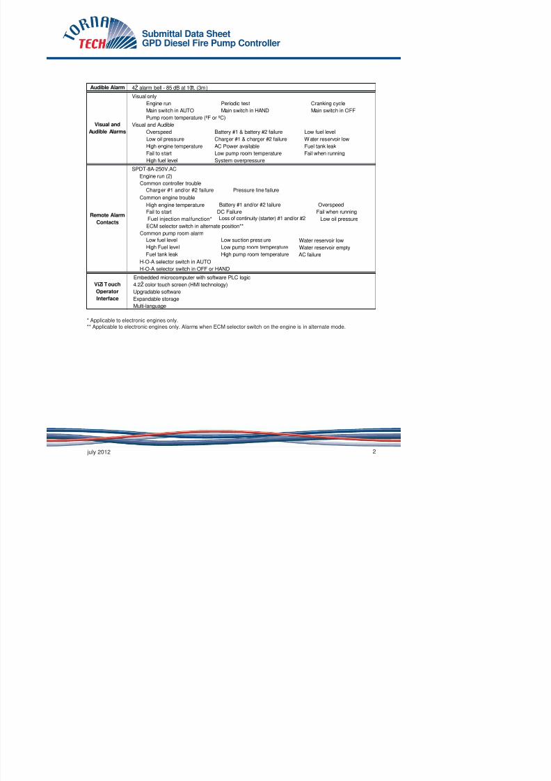
7/17/2019 Tech Data 1500 Gpm - For Power Island System Rev.01
http://slidepdf.com/reader/full/tech-data-1500-gpm-for-power-island-system-rev01 78/101
FM GlobalNew York City
CE Mark
NEMA 12 NEMA 4X-304 sst painted IP54NEMA 3 NEMA 4X-304 sst brushed finish IP55NEMA 3R NEMA 4X-316 sst painted IP65NEMA 4 NEMA 4X-316 sst brushed finish IP66
Accessories
Bottom entry gland plate Wall mounting lugs Keylock handle
Grounding system
10A continuous charge 500mA trickle charge
Pressure readings with date stamp Event recording with date stamp
Under regular maintained operation, events can be stored in memory for up to 5 years Data viewable on operator interface display screenDownloadble by USB port to external memory device
Pressure
Readings
Continuous system pressure display Cut-in and Cut-out pressure settings
Pressure and
Event
Recorder
Standard,
Listings,
Approvals and
Certifications
Built to NFPA 20 (latest edition)
Underwriters Laboratory (UL)UL218 - Fire pump controllersCSA C22.2 No. 14 Industrial Control EquipmentClass 1321/1323Accepted for use in the City of New York by the Department of Buildings
Optional
Various EN, IEC & CEE directives and standards
Enclosure
Protection Rating
Standard: NEMA 2 (IP31)Optional
Paint Specifications
Electrical
Readings
Battery 1 & Battery 2 voltageBattery 1 & Battery 2 charging amperage Charging mode
Red RAL3002 Powder coating Glossy textured finish
General
AC
DC
Battery chargers
120V/1ph/60hz 208V to 240V/1ph/50-60hz 12VDC 24VDC Negative Two independent fully automatic
Submittal Data SheetGPD Diesel Fire Pump Controller

7/17/2019 Tech Data 1500 Gpm - For Power Island System Rev.01
http://slidepdf.com/reader/full/tech-data-1500-gpm-for-power-island-system-rev01 79/101
Audible Alarm
Engine run Periodic test Cranking cycle Main switch in AUTO Main switch in HAND Main switch in OFF
Overspeed Battery #1 & battery #2 failure Low fuel level Low oil pressure Charger #1 & charger #2 failure Water reservoir low High engine temperature AC Power available Fuel tank leak Fail to start Low pump room temperature Fail when running High fuel level System overpressure
Charger #1 and/or #2 failure Pressure line failure
High engine temperature Battery #1 and/or #2 failure Overspeed Fail to start DC Failure Fail when running Fuel injection malfunction* Loss of continuity (starter) #1 and/or #2 Low oil pressure
Low fuel level Low suction pressure Water reservoir low High Fuel level Low pump room temperature Water reservoir empty Fuel tank leak High pump room temperature AC failure
Expandable storage
4Ž alarm bell - 85 dB at 10ft. (3m)
Common controller trouble
Common engine trouble
H-O-A selector switch in AUTO H-O-A selector switch in OFF or HAND
Remote Alarm
Contacts
SPDT-8A-250V.AC Engine run (2)
Common pump room alarm
ViZi Touch
Operator
Interface
Embedded microcomputer with software PLC logic 4.2Ž color touch screen (HMI technology) Upgradable software
Multi-language
Visual and
Audible Alarms
ECM selector switch in alternate position**
Visual only
Visual and AudiblePump room temperature (ºF or ºC)
* Applicable to electronic engines only.** Applicable to electronic engines only. Alarms when ECM selector switch on the engine is in alternate mode.
Submittal Data SheetGPD Diesel Fire Pump Controller

7/17/2019 Tech Data 1500 Gpm - For Power Island System Rev.01
http://slidepdf.com/reader/full/tech-data-1500-gpm-for-power-island-system-rev01 80/101
Minimum run timer ***(off delay) Sequential start timer (on delay) Periodic test timer PressureNon-pressure Automatic Non-automatic
*** Automatic shutdown shall be approved by the AHJ.
Start on pressure dropRemote start signal from automatic device
Manual Start
Crank 1 and Crank 2 start pushbuttons Run test pushbutton Deluge valve start
Remote start from manual device
Selector Switch
Timers
3 X 15s crank from battery 1 or 2 alternativelyOperation
15s rest in between each crank attempt
StoppingManual with Stop pushbutton Automatic after expiration of minimum run timer ***
HAND-OFF-AUTO Behind lockable and breakable cover
Automatic Start
Actuation
ModeVisual Indication
Field Adjustable & Visual Countdown
Crank Cycle 6 consecutive cycle attempts
Manual Start Or Remote Start Run Test or Periodic test
Alarm only ShutdownAlarm Only ShutdownShutdown Shutdown
Alarm &
Shutdown
Schedule
Automatic Start
High Coolant Alarm onlyLow Oil Pressure Alarm only
Overspeed Shutdown
Dimensions in inches (mm)
Approx. Shipping Weight in
Lbs (kg) Dimensions in inches (mm)
Approx. Shipping Weight in
Lbs (kg)
27-5/8"h x 23-3/4"w x 9"d 50"h x 23-3/4"w x 9"d
(700 x 600 x228 ) (1220 x 600 x 228)
Wall Mount Floor Mount
120 (55) 145 (67)
Submittal Data SheetGPD Diesel Fire Pump Controller

7/17/2019 Tech Data 1500 Gpm - For Power Island System Rev.01
http://slidepdf.com/reader/full/tech-data-1500-gpm-for-power-island-system-rev01 81/101
A1 Periodic test alarm contact (Form C-SPDT)A2 Overspeed alarm contact (Form C-SPDT)A3 Low oil pressure alarm contact (Form C-SPDT)
A4High coolant temperature alarm contact(Form C-SPDT)
A5Failure to start alarm contacts alarm contact(Form C-SPDT)
A6Battery 1 & 2 failure alarm contact
(2 x Form C-SPDT)A7
Charger 1 & 2 failure alarm contact(2 x Form C-SPDT)
A8 AC failure alarm contact (Form C-SPDT)
A9System overpressure alarm contact(For engines with PLD) (Form C-SPDT)
A11Extra controller trouble alarm contact(Form C-SPDT)
A12Extra engine trouble alarm contact(Form C-SPDT)
AxAdditional engine alarm contact alarm contact(Form C-SPDT) (specify function)
B1 Low fuel level alarm contact (Form C-SPDT)
B2Water reservoir level low alarm contact(Form C-SPDT)
B3Water reservoir empty alarm contact(Form C-SPDT)
B4Low pump room temperature alarm contact(Form C-SPDT)
B5 High fuel level alarm contact (Form C-SPDT)
B6
Low system (discharge) pressure alarm contact
(Form C-SPDT)
B7Low suction pressure alarm contact(Form C-SPDT)
B8 Pump on demand alarm contact (Form C-SPDT)B9 Fuel tank leak alarm contact (Form C-SPDT)
B10Main relief valve open alarm contact(Form C-SPDT)
B11Flow meter loop valve open alarm contact(Form C-SPDT)
B12Water reservoir level high alarm contact
(Form C-SPDT)B13
High pump room temperature alarm contact(Form C-SPDT)
BxAdditional pump room alarm contact(Form C-SPDT) (specify function)
C5 CE Mark with factory certificate
C14Delayed automatic start on AC power failure(factory set at 15 minutes)
C15 Low zone pump control functionC16 Medium zone pump control functionC17 High zone pump control function
C19Lockout/interlock circuit from equipment installedinside the pump room
D4
Pressure transducer and run test solenoid valve
for fresh water rated for 0-500 PSI (for calibrationpurposes only)
D6Pressure transducer and run test solenoid valvefor sea water rated for 0-500 PSI
D7ALow fuel level float switch supplied as separateitem (1.1/4Ž)
D7BLow fuel level float switch supplied as separateitem (1.1/2Ž)
D8AHigh fuel level float switch supplied as separateitem (1.1/4Ž)
D8B
High fuel level float switch supplied as separate
item (1.1/2Ž)D9A Anti-condensation heater & thermostatD9B Anti-condensation heater & humidistat
D9CAnti-condensation heater & thermostat &humidistat
D11Low suction pressure transducer for fresh waterrated for 0-300PSI with visual indication and alarmcontact
D11ALow suction pressure transducer for sea waterrated for 0-300PSI with visual indication and alarm
contactD12 TropicalizationD17 French labelingD18 Spanish labelingD19 Other languagesD25 Mounting standD25A Mounting stand SST- 304 paintedD25B Mounting stand SST- 304 brushed finishD25C Mounting stand SST- 316 paintedD25D Mounting stand SST- 316 brushed finish
D26 Combined low and high fuel level float switch(1- 1/4Ž)
D26ACombined low and high fuel level float switch(1-1/2Ž)
D27 Fuel level probe (1-1/4Ž) Level indicationD28 Field programmable I/O board - 8 input / 5 output
Submittal Data SheetGPD Diesel Fire Pump Controller

7/17/2019 Tech Data 1500 Gpm - For Power Island System Rev.01
http://slidepdf.com/reader/full/tech-data-1500-gpm-for-power-island-system-rev01 82/101
1 Power LED 8 USB port
ViZiTouch Operator Interface
??
4
9 10
12 13
11
14
5 6 7
3
2
1
8
21

7/17/2019 Tech Data 1500 Gpm - For Power Island System Rev.01
http://slidepdf.com/reader/full/tech-data-1500-gpm-for-power-island-system-rev01 83/101

7/17/2019 Tech Data 1500 Gpm - For Power Island System Rev.01
http://slidepdf.com/reader/full/tech-data-1500-gpm-for-power-island-system-rev01 84/101

7/17/2019 Tech Data 1500 Gpm - For Power Island System Rev.01
http://slidepdf.com/reader/full/tech-data-1500-gpm-for-power-island-system-rev01 85/101

7/17/2019 Tech Data 1500 Gpm - For Power Island System Rev.01
http://slidepdf.com/reader/full/tech-data-1500-gpm-for-power-island-system-rev01 86/101
qwertyuiopasdfghjklzxcvbnmqwertyuiopasdfghjklzxcvbnmqwertyuiopasdfgh
kl b df h kl b

7/17/2019 Tech Data 1500 Gpm - For Power Island System Rev.01
http://slidepdf.com/reader/full/tech-data-1500-gpm-for-power-island-system-rev01 87/101
jklzxcvbnmqwertyuiopasdfghjklzxcvbnmqwertyuiopasdfghjklzxcvbnmqwer
tyuiopasdfghjklzxcvbnmqwertyuiopasdfghjklzxcvbnmqwertyuiopasdfghjklzx
cvbnmqwertyuiopasdfghjklzxcvbnmq
wertyuiopasdfghjklzxcvbnmqwertyuio
pasdfghjklzxcvbnmqwertyuiopasdfghj
klzxcvbnmqwertyuiopasdfghjklzxcvbn
mqwertyuiopasdfghjklzxcvbnmqwerty
uiopasdfghjklzxcvbnmqwertyuiopasdf ghjklzxcvbnmqwertyuiopasdfghjklzxc
Spare Part List BookController Model : GPD
PERTAMINA BALIKPAPAN
‐DEPOT
PANGKALAN
BUN,
DEPOT PULANG PISAU, DPPU JUWATA
Prepared by : PT. Roda Nurmala
JOCKEY PUMP
Aurora Vertical Multistage In-Line
Model : PVM 10 - 14
COAL FIRED POWER STATION,BABELAN

7/17/2019 Tech Data 1500 Gpm - For Power Island System Rev.01
http://slidepdf.com/reader/full/tech-data-1500-gpm-for-power-island-system-rev01 88/101
Customer :Project name : Default Pump Performance DatasheetEncompass 2.0 - 15.1.3.0
Item number : 012Service :Quantity : 1Quote number : 259241
Size : PVM(X)15-9Stages : 9Based on curve number : PVM(X)15-9-50HzDate last saved : 20 May 2015 4:37 AM
Operating Conditions
Flow, rated : 12.00 m3/h
Differential head / pressure rated (requested) : 11 00 bar
Liquid
Liquid type : Water
Additional liquid description :
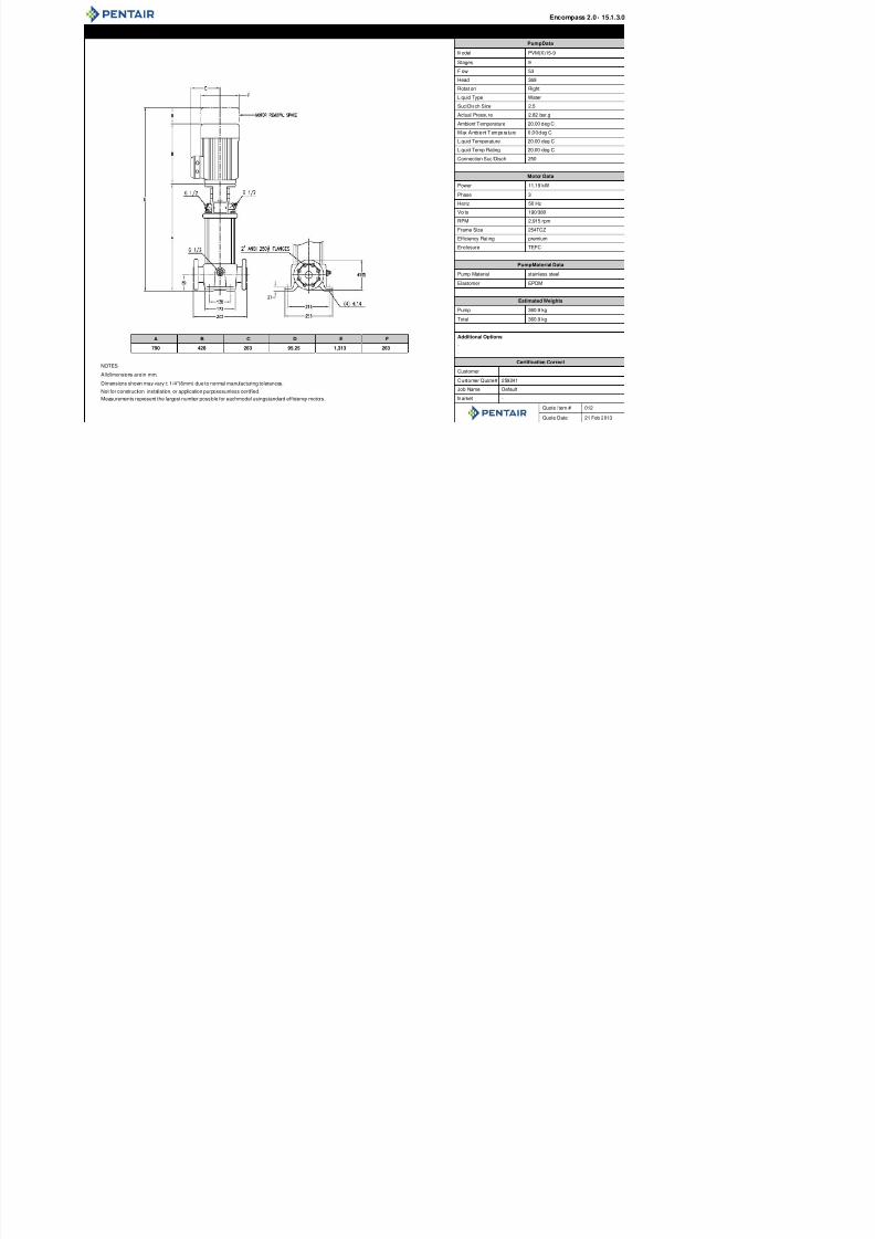
7/17/2019 Tech Data 1500 Gpm - For Power Island System Rev.01
http://slidepdf.com/reader/full/tech-data-1500-gpm-for-power-island-system-rev01 89/101
Differential head / pressure, rated (requested) : 11.00 barDifferential head / pressure, rated (actual) : 11.50 barSuction pressure, rated / max : 0.00 / 0.00 bar.gNPSH available, rated : AmpleFrequency : 50 HzPerformance
Speed, rated : 2,915 rpmImpeller diameter, rated : PVM(I/X)15-9Impeller diameter, maximum : PVM(I/X)15-9Impeller diameter, minimum : PVM(I/X)15-9
Efficiency : 64.42 %NPSH required / margin required : - / 0.00 mnq (imp. eye flow) / S (imp. eye flow) : N/A Metric unitsMinimum Continuous Stable Flow : 8.51 m3/hHead, maximum, rated diameter : 12.45 barHead rise to shutoff : 8.28 %Flow, best eff. point (BEP) : 18.49 m3/hFlow ratio (rated / BEP) : 64.89 %Diameter ratio (rated / max) : 100.00 %Head ratio (rated dia / max dia) : 100.00 %
Cq/Ch/Ce/Cn [ANSI/HI 9.6.7-2010] : 1.00 / 1.00 / 1.00 / 1.00Selection status : Acceptable
Additional liquid description :Solids diameter, max : 0.00 mmSolids concentration, by volume : 0.00 %Temperature, max : 20.00 deg CFluid density, rated / max : 0.998 / 0.998 kg/dm3Viscosity, rated : 1.00 cStVapor pressure, rated : 0.02 bar.aMaterial
Material selected : Not specifiedPressure Data
Maximum working pressure : 12.45 bar.gMaximum allowable working pressure : N/AMaximum allowable suction pressure : N/AHydrostatic test pressure : N/ADriver & Power Data
Driver sizing specification : Rated powerMargin over specification : 0.00 %Service factor : 1.15 (used)Power, hydraulic : 3.83 kW
Power, rated : 5.95 kWPower, maximum, rated diameter : 7.30 kWMinimum recommended motor rating : 11.19 kW / 15.00 hp (Fixed)
0.0
2.5
5.0
7.5
10.0
P o w e r - k W
Power
6.0
7.5
9.0
10.5
12.0
13.5
15.0
H e a d - b a r
PVM(I/X)15-9
5158
6367
67
69
69
70
70
Minimum Continuous Stable Flow
Preferred operating region
General Arrangement DrawingPumpData
Model PVM(X)15-9
Stages 9
Flow 53
Head 369
Rotation Right
Liquid Type Water
Suc/Disch Size 2.5
Actual Pressure 2.82 bar.g
Ambient Temperature 20 00 deg C
Encompass 2.0 - 15.1.3.0

7/17/2019 Tech Data 1500 Gpm - For Power Island System Rev.01
http://slidepdf.com/reader/full/tech-data-1500-gpm-for-power-island-system-rev01 90/101
A B C D E F
790 428 263 95.25 1,313 263
NOTES:
Alldimensions arein mm.
Dimensions shown may vary ± 1/4"(6mm) due to normal manufacturing tolerances.
Not for construction, installation, or application purposesunless certified.
Measurements represent the largest number possible for eachmodel usingstandard efficiency motors.
Ambient Temperature 20.00 deg C
Max Ambient Temperature 0.00deg C
Liquid Temperature 20.00 deg C
Liquid Temp Rating 20.00 deg C
Connection Suc/Disch 250
Motor Data
Power 11.19 kW
Phase 3
Hertz 50 Hz
Volts 190/380
RPM 2,915 rpm
Frame Size 254TCZ
Efficiency Rating premium
Enclosure TEFC
PumpMaterial Data
Pump Material stainless steel
Elastomer EPDM
Estimated Weights
Pump 360.9 kg
Total 360.9 kg
Additional Options
-
-
Certification Correct
Customer
Customer Quote# 259241
Job Name Default
Market -
Quote Item # 012
Quote Date 21 Feb 2013
VERTICAL MULTISTAGE CENTRIFUGAL PUMPS
PVM(X)
PUMP CONSTRUCTION
POS. NAME MATERIAL PVM 1, 3, 5, 10, 15, 20 PVMX 1, 3, 5, 10, 15, 20
36 Pump Head Cast Iron EN GJL 200 ; ASTM 25B EN-GJS-450-10 ; ASTM

7/17/2019 Tech Data 1500 Gpm - For Power Island System Rev.01
http://slidepdf.com/reader/full/tech-data-1500-gpm-for-power-island-system-rev01 91/101
PVM – 1, 3, 5, 10, 15, 20 PVMX – 1, 3, 5, 10, 15, 20
36 Pump Head Cast Iron EN-GJL-200 ; ASTM 25B EN GJS 450 10 ; ASTM65-45-12
56 Pump Head Cover Stainless Steel - 1.4401 ; AISI 316
18 Impeller Stainless Steel 1.4301 ; AISI 304 1.4401 ; AISI 316
37 Shaft Stainless Steel 1.4057 ; AISI 431 1.4401 ; AISI 316
48 Outer Sleeve Stainless Steel 1.4301 ; AISI 304 1.4401 ; AISI 316
82O-Ring for Outer
SleeveEPDM - -
12 Chamber Stainless Steel 1.4301 ; AISI 304 1.4401 ; AISI 31624 Neck Ring PTFE - -
59 Base Cast Iron EN-GJL-200 ; ASTM 25B -
Stainless Steel - 1.4401 ; AISI 316
62 Base Plate Cast Iron - EN-GJL-200 ; ASTM 25B
44 Coupling Fe-Cu-C SINT C11 ; MPIF FC0525 SINT C11 ; MPIF FC0525
57 Mechanical Seal Cartridge Type - -
Jockey Pump ControllerReduced Voltage Wye-delta Open Starter
JPY M o d e l

7/17/2019 Tech Data 1500 Gpm - For Power Island System Rev.01
http://slidepdf.com/reader/full/tech-data-1500-gpm-for-power-island-system-rev01 92/101
Reduced Voltage Wye delta Open StarterSolid State Controls with Digital
Operator Interface
The model JPY jockey pump controllers are specifically
designed to control jockey pumps in order to maintain
the desired water pressure in fire pump serviced systems.
A jockey pump installation prevents unnecessary startingof the fire pump due to small leaks in the sprinkler system
piping.
motor run, system pressure above stop pressure
setting, system pressure in-between start and stop
pressure setting and system pressure below start
pressure setting.
The standard power circuit consists of a horsepower
rated disconnect switch, a wye-delta open transition
ti t t t d th ti t
Standard Features:
• Solid state controls with digital iPD+operator interface
• All adjustments on door front• Visual indicators • Manual motor run • Automatic motor run • System pressure • Automatic mode
• Off mode • Motor overload • Pump start counter
•
Elapsed time meter(hours / non-resettable)
• Timers• Minimum run period timer
• Sequential start timer• Operators • OFF-AUTO pushbutton
• Start and stop pushbuttons• NEMA 2 enclosure• Pressure transducer• Wye-delta open transition fuseless magnetic motor starter
JPY
6
Operator Interface
M o d e l
7

7/17/2019 Tech Data 1500 Gpm - For Power Island System Rev.01
http://slidepdf.com/reader/full/tech-data-1500-gpm-for-power-island-system-rev01 93/101
HOW TO ORDER: JPx - V / HP / Ph / Hz
Ex.: JPY - 208 / 2 / 3 / 60
2
3
45
6
1
1 - High luminosity four digit digital display2 - System status diagnostic LED’s for:
i. Green: system pressure at or above cut-outvalue
ii. Yellow: system pressure between cut-inand cut-out
iii. Red: system pressure at or below cut-in value3 - Motor run LEDs (manual start or automatic start)
Americas Europe Middle East Asia
4 - Start and stop pushbuttons5 - Navigation keypad6 - OFF-AUTO position pushbutton and visual
indication (LED)7 - Horsepower rated door interlocked rotary type disconnect switch8 - Wye-delta open transition fuseless magnetic motor starter with thermo-magnetic motor
protector9 - Pressure transducer with 0-600psi
range and 316 stainless steel construction
9
8
Technical Data
Model JPY Jockey Pump Controller

7/17/2019 Tech Data 1500 Gpm - For Power Island System Rev.01
http://slidepdf.com/reader/full/tech-data-1500-gpm-for-power-island-system-rev01 94/101
Underwriters Laboratory (UL) UL508A - Industrial Pump Controllers
CSA CSA C22.2 No. 14 Industrial Control Equipment
New York City Accepted for use in the City of New York by the Department of Buildings
Optional
CE Mark Various EN, IEC & CEE directives and standards
Standard: NEMA 2 (IP31)
Optional
NEMA 12 NEMA 4X-304 sst painted
Reduced Voltage
100%
Inrush Current: 33% of normal load current
33%
Motor Type:
2 at 58%, 1 at 33% of motor FLC
OL1
C1
T1T1
C2
T2
T3
T2
T3
T6T6
T4T4
T5 T5
C3
P1
T h i l D t S b itt l D t
Project:
Customer:

7/17/2019 Tech Data 1500 Gpm - For Power Island System Rev.01
http://slidepdf.com/reader/full/tech-data-1500-gpm-for-power-island-system-rev01 95/101
Model JPY
Wye-Delta Open Transit ion Start
Jockey Pump Control ler
Technical Data Submittal Document
Contents:
Technical Data
Model JPY Jockey Pump Controller

7/17/2019 Tech Data 1500 Gpm - For Power Island System Rev.01
http://slidepdf.com/reader/full/tech-data-1500-gpm-for-power-island-system-rev01 96/101
Wye-Delta
Open Transition
Starter
Control Circuit
iPD+ Operator
Visual Indications
Timers
Counters
Operators
Operation
Automatic Start Start on pressure drop
Manual Start Start pushbutton
Stopping Stop pushbutton
Technical Data
Model JPY Jockey Pump Controller
A4 Elapsed time meter (time totalizer) L01

7/17/2019 Tech Data 1500 Gpm - For Power Island System Rev.01
http://slidepdf.com/reader/full/tech-data-1500-gpm-for-power-island-system-rev01 97/101
A4 Elapsed time meter (time totalizer)
A5 Motor run alarm contact
A6 Loss of power alarm contact
A7
A7A
D12
D13A
D14
D18 Audible alarm
D19 Anti-condensation heater and thermostat
D20 Anti-condensation heater and humidistat
D21
D22
D23 Controller power healthy pilot light and alarm contact
D24
Pump failure via current sensing relay with pilot light and dry
alarm contact
D25 Low zone pump control function
D26 Mid zone pump control function
D27 High zone pump control function
D28 Selector switch in auto alarm contacts
D29 Selector switch in off alarm contacts
D30 Motor heater circuit
D32
Service entrance rated - 100kA short circuit withstand rating:
D33
Service entrance rated - 65kA short circuit withstand rating:
D34Service entrance rated - 42kA short circuit withstand rating:
L01
L02 French
L03 Spanish
L04
L05 Italian
L06 Polish
L07 Romanian
L08 Hungarian
L09 Slovak
L10 Croatian
L11 Czech
L12 Portuguese
L13 Dutch
L14 Russian
L15
L16 Swedish
L17 Bulgarian
L18
L19 Indonesian
L20 Slovenian
Technical Data
Model JPY Jockey Pump Controller
iPD+
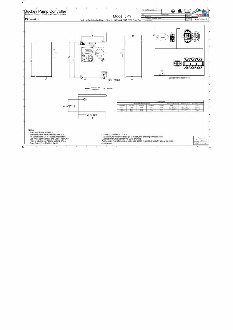
7/17/2019 Tech Data 1500 Gpm - For Power Island System Rev.01
http://slidepdf.com/reader/full/tech-data-1500-gpm-for-power-island-system-rev01 98/101
iPD
AUTOHAND
9
5
6
32
1
8
74
JPY-DI500 /E
ModelDimension
:JPY
NYCDpt of Building
Approved
Drawing No.
DD/MM/YYDESCRIPTION
PER QUOTE DRAWING No.
REV.
Jockey Pump Controller Reduced Voltage / Wye Delta (Open Transition)
DF C
FU13L21L1
5L3
DS1OL1
0 First Issue 24/07/14
1 Dimension Table and Notes 17/10/14
Built to the latest edition of the UL 508A & CSA C22.2 No.14 2 IPD+ R221B 23/01/14
3 4 5 6 720 1 8
B
A A
B

7/17/2019 Tech Data 1500 Gpm - For Power Island System Rev.01
http://slidepdf.com/reader/full/tech-data-1500-gpm-for-power-island-system-rev01 99/101
Projection
Standard Internal Layout
Dimension Enclosure Dimension Door Dimension Anchor
Dimension*Maximum Motor Horsepower
Main Disconnect
RatingLabel
- All Dimensions are in Inches [Millimeters]- Use Watertight Conduit and Connector Only.- Protect Equipment Against Drilling Chips.
Notes:
Sensing Line
Connection
DS
ON
O F F
D A N G E R
F C
EG
A
B
38 "[9] x4
HAND AUTO
G
Y
R
GG
- Door Swing Equal to Door Width
E NCLO S E D INDUS T RIA L CO NT RO L P A NE L
Laboratori es Inc .
No. A C-X X X
LIS T E D
Underwri te rs
NYC
- Standard NEMA: NEMA 2- Standard Paint: Textured Red RAL 3002.
PT1
T 1
T 2
T 3
T 5
T 4
T 6
C3
XTR12T1 4T2 6T3
C2 C1
Manufacturer reserves the right to modify this drawing without notice.Contact manufacturer for "As Built" drawing.-*Dimension may change depending on option required. Consult Factory for exact
dimensions.
- Drawing for information only.
A X B X C
TBD TBD
TBD
D X E F X G200-208V
7.5HP
20HP
30HP
220-240V
7.5HP
380-416V
15HP
30HP
40HP
440-480V
20HP
50HP
60HP
575-600V
25HP
60HP
N/A
20HP
30HP
1/4 " M.NPT
G
H
C
D
E
F
I
3 4 5 6 720 1 8
G
H
I
C
D
E
F
ModelWiring schematic JPY-WS500 /E
:JPY
NYCDpt of Building
Approved
Drawing No.
DD/MM/YYDESCRIPTION
PER QUOTE DRAWING No.
REV.
Jockey Pump Controller Reduced Voltage / Wye Delta (Open Transition)
L1 L3L2
DSG
0 First Issue 24/07/14
1 Remove Dimension Table 17/10/14
Built to the latest edition of the UL 508A & CSA C22.2 No.14
B l a c k
Pressure Sensor
W h i t e
G r e e n
R e d
Type 0-100mV
P T 1
G
Y
R
RGWB 5 S
2 IPD+ R221B 23/01/14
3 4 5 6 720 1 8
B
A A
B

7/17/2019 Tech Data 1500 Gpm - For Power Island System Rev.01
http://slidepdf.com/reader/full/tech-data-1500-gpm-for-power-island-system-rev01 100/101
FU1
X2
X1
XTR1
H1
H2 3
1
OL1
C1
T1
C2
T2 T3T6 T4 T5
G
T 3T 2T 5 T 1T 4T 6
C3
P1
C1 A1 A2
C113 14 10
C313 14
C31221 22
C21421 22
C2 A1 A2
C3 A1 A2
C167 68
C155 56
11
13
Manufacturer reserves the right to modify this drawing without notice.Contact manufacturer for "As Built" drawing.
- Drawing for information only.
HAND AUTOGG
P s I n -
P s O u t -
P s O u t +
P s I n +
A2
RESET
F5
" IPD+"
J2
J5
J8
J3 J1
J9
OUTPUT ON
A1
G
3 1 22 8
24Vac24Vac
J19
A2
A1
A2
A1
OUT2
OUT1
24Vdc
J21
IN2
IN1
G
H
C
D
E
F
I
3 4 5 6 720 1 8
G
H
I
C
D
E
F
OL17 A1 A2
9
Model:JPY
NYCDpt of Building
Approved
Drawing No.
DD/MM/YYDESCRIPTION
PER QUOTE DRAWING No.
REV.
Jockey Pump Controller Reduced Voltage / Wye Delta (Open Transition)
3 Phases
Power Connections and Motor Connections
Built to the latest edition of the UL 508A & CSA C22.2 No.14 JPY-TD500 /E
0 First Issue 24/07/14
1 Remove Dimension Table 17/10/14Line and Motor Terminal Size 2 IPD+ R221B 23/01/14
3 4 5 6 720 1 8
B
A A
B

7/17/2019 Tech Data 1500 Gpm - For Power Island System Rev.01
http://slidepdf.com/reader/full/tech-data-1500-gpm-for-power-island-system-rev01 101/101
L2L1
DS
L3
P1
C2 C1
T6 T 4 T5 T1 T2 T3
200-208V
7.5HP #14 AWG - #8 AWG 1.8 Nm
10HP #12 AWG - #4 AWG 1.8 Nm
15HP #4 AWG - #1/0 AWG 5.65 Nm
200-208V
7.5HP #14 AWG - #10 AWG 1 Nm
20HP #16 AWG - #6 AWG 1.5 Nm
30HP #10 AWG - #2 AWG 2 Nm
220-240V
7.5HP
380-416V
15HP
30HP
40HP
440-480V
20HP
50HP
60HP
575-600V
25HP
60HP
N/A
#14 AWG - #2 AWG
#14 AWG - #2 AWG
#6 AWG - #2 AWG
#14 AWG - #2 AWG
#12 AWG - #2 AWG
#12 AWG - #2 AWG
220-240V
10HP
10HP
15HP
380-416V
15HP
20HP
25HP
440-480V
20HP
25HP
30HP
575-600V
15HP
25HP
40HP
20HP
30HP
Line Terminals (L1,L2,L3,GND)
Maximum Motor Horsepower Wire Size Copper Only Torque
Motor Terminals (T1,T2,T3,T4,T5,T6,GND)
Maximum Motor Horsepower Wire Size Copper Only Torque
Wire Size Ground Copper Only
Wire Size Ground Copper
Only
Bonding Ground
3 Phases
Incoming Power
G
H
C
D
E
F
I
3 4 5 6 720 1 8
G
H
I
C
D
E
F