team k-tron team members: ryan vroom geoff cunningham trevor mcclenathan brendan tighe
Post on 21-Dec-2015
227 views
TRANSCRIPT

Team K-TRON
Team Members:Ryan Vroom
Geoff CunninghamTrevor McClenathan
Brendan Tighe

Outline• Project definition• Overview of design process
> Important decisions made with rationale
• Concept selection> Concept chosen with validation
• Implementation plan• Final remarks

Project Scope
» Design a testing apparatus to produce external vibration to the SFTII load cell under specific loading
Metrics:• Apply mass of 120 kg in 6
increments• Frequency range: Achieve 120 Hz
(112 Hz “magic number”) and as low as possible
• Acceleration range: 0.05 g – 0.3 g• Max displacement of 1 mm
SFTII

Adding Value to Sponsor’s Business
• Exact modeling can increase load cell accuracy-Filtering out environmental noise
• Allow K-TRON to remain as the “World’s number one feeder company”
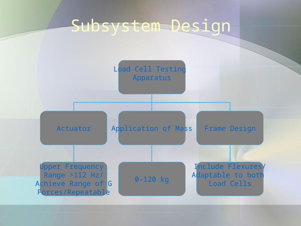
Subsystem Design
Load Cell Testing Apparatus
Actuator Application of Mass Frame Design
Include Flexures/Adaptable to both
Load Cells0-120 kg
Upper Frequency Range >112 Hz/
Achieve Range of GForces/Repeatable

Benchmarking: ActuatorBose Electro-Magnetic Linear Drive:• Cost: ~ $35,000.00!• Production time ~ 3 years
Parker Linear Actuator:•Can only work up to 100 Hz •Requires load relieving•Expensive: Actuator/Controller combo costs ~$11,000.00

Benchmarking: Actuator
BEI Kimco Voice-Coil Linear Actuator:
• Max load of 13.5 kg
Piezomechanik Piezoelectric Actuator:•Will need a very powerful controller (1000V output) to work•Actuator/Controller combo= $13,880

Benchmarking: Chosen Actuator
• After checking calculations, determined lower voltage actuator could be used
d=amplitude
a=gravitational force
Results Determined:
» Low end frequency at low g force – 27 Hz at 0.05 g’s
» Low end frequency at high g force – 68 Hz at 0.3 g’s
daf
4
1
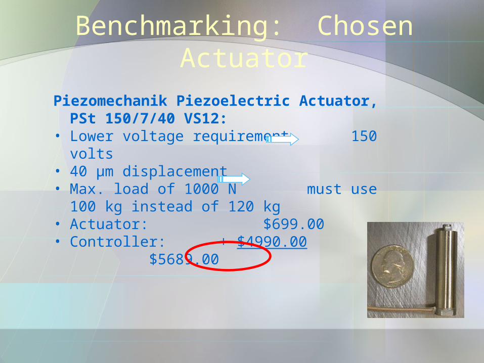
Benchmarking: Chosen Actuator
Piezomechanik Piezoelectric Actuator, PSt 150/7/40 VS12:
• Lower voltage requirement 150 volts• 40 µm displacement• Max. load of 1000 N must use 100
kg instead of 120 kg• Actuator: $699.00• Controller: + $4990.00
$5689.00

Actuator: Cost Analysis
Actuator Cost Analysis
Concept Description Cost
1 Electro-Magnetic Linear Drive $35,000
2 Parker Linear Actuator $11,000
3 BEI Kimco Voice-Coil $900
4Piezomechanik Piezoelectric
System (1000 V) $13,880
5Piezomechanik Piezoelectric
System (150 V)
$5,689

Benchmarking: Load Application
Machined steel:• Cost of material greater than $115 per
20 kg mass• High machining timeMachined lead:• Toxic issues• Cost of material greater than $140 per
20 kg mass• High machining time45 lb weights:• High resultant moment

25 lb. cast plates:• Small, circular shape reduces unwanted
moment forces during testing• Pre-bored center hole reduces
machining time• Low cost of $13.99 per 11.3 kg
Benchmarking: Chosen Loading Application

Benchmarking: Chosen Loading Application
• Weight selection determined center rod:– 1.25 in. acme threaded rod-rod diameter
ideal for existing hole and cost– Acme threaded collar to minimize movement
of weights during testing – Analysis of rod under worst case scenario,
assume cantilevered beam w/ distributed load
» Safety factor of 5.7
• Center hole diameter of weights, 2-1/32 in.– Machine aluminum inserts that are press-
fitted - provide slip fit between rod and plate

Loading Design: Cost AnalysisMass Loading
Parts:
# Description Cost Ea. ($) Cost ($)
12 25 lb. weight 13.99 167.88
1 Acme Threaded Collar 19.78 19.78
13 ft. Acme Threaded
Rod 40.43 40.43
12 Weight Inserts 0 (scrap) 0
Total Cost ($) 228.09
Machining:
Time (hrs.) Cost per hour Cost ($)
~20 free 0
Overall Cost excluding shipping ($) 228.09

Exploded System Design
1) Base Plate2) Steel Supports3) Steel Struts4) Support Blocks5) Flexure6) Flexure Connector7) Weight Post8) Rod Connecting screw9) Load Cell10) Actuator Connecting Screw11) Actuator12) Actuator Stabilizer
12
3
4
56
7
98
11
10
12
4

Completed System Design

Frame Design: Steel Support Tubing
Main structural parts made of 1008 steel• 24” x 24” x 1” base plate• 1” x 1” square tubing• Support blocks
– All steel parts welded to increase rigidity
1008 steel properties:• Elastic Modulus ~ 29,000 ksi• Tensile strength ~ 49.3 ksi• Yield Strength ~ 41.3 ksi
Base plate
Square tubing
Support block

Frame Design: Finite Element Analysis
•Steel square tube with 80 N shear load at tip
•Maximum deformation of 9.42e-4 in.
•Factor of Safety > 9.6

Frame Design: Flexure
Flexures connect threaded rod to steel supports• Reduces lateral motion of the rod• All applied stresses are tensile

Frame Design: Finite Element Analysis
•Stainless steel flexure device with 45 N tensile load applied at right cutout
•Maximum deformation of 4.26e -3 in.
•Factor of Safety > 8.7

Frame Design: Actuator Support
After speaking with Dr. Sun on possible failure:• Actuator support will be bolted to base plate
using the four pre-existing screw holes• The support will keep Actuator from buckling
under high loads
ActuatorActuator support

Frame Design: Load Cell/Actuator Connector
•Steel bolt body with 1000 N compression load applied at center gives factor of safety > 4.17
•Effective loading difference on face is 471N
•Maximum deformation of 1.5e -5 in.

Frame Design: Cost Analysis
Frame System Cost Analysis
Parts:
# Description Cost Ea. ($) Cost ($)
1 Steel Plate 421.63 421.63
1Steel Square
Tube 19.43 19.43
2 Flexures 0 (in house) 0
1Alum. 6” x 6”
Block 0 (scrap) 0
1Alum. Flexure
Connector 0 (scrap) 0
5 M8 Bolts 0 (in house) 0
8 M4 Bolts 0 (in house) 0
Total Cost ($) 441.06
Machining:
Time (hrs.) Cost per hour Cost ($)
~20 free 0

Overall Cost Analysis
Mass Loading Cost
All Supplies $228.09
Frame System Cost Total System Cost
All Supplies $441.06 $6,358.1
5
Actuator System Cost
All Supplies $5,689.00

Implementation Plan• Test the as-built apparatus to
complete validation of design (in process)
• Manufacture SFTIII adaptation mount
• We will hand-off the project to K-Tron so they can test their load cells
Acknowledgements
• Thank you to our sponsor at K-Tron:– Tim Baer– Jim Foley
• Thanks to our advisor:– Dr. Keefe
• Special thanks to:– Steve Beard

QuestionsExploded View

Frame Design: Finite Element Analysis
•Steel SFTIII adapter support with 720 N applied load at attached face
•Maximum deformation of 2.447e-4 in.
•Factor of Safety > 100 with full load (1600 N) applied