team 65 project technical report to the 2018 spaceport ... · team 65 project technical report to...
TRANSCRIPT
Team 65 Project Technical Report to the 2018 Spaceport America Cup
Matt Valenzeno 1
University of Illinois at Chicago, Chicago, Illinois, 60607
Rachel Cruz 2
University of Illinois at Chicago, Chicago, IL, 6007, United States
Marcin Maksimowicz 3
University of Illinois at Chicago, Chicago, IL, 6007, United States
Marek Maksimowicz 4
University of Illinois at Chicago, Chicago, IL, 6007, United States
Corey Habel 5
University of Illinois at Chicago, Chicago, IL, 6007, United States
Michal Pekalal 6
University of Illinois at Chicago, Chicago, IL, 6007, United States
Patrick Begalowski 7
University of Illinois at Chicago, Chicago, IL, 6007, United States
Barak Stolz 8
University of Illinois at Chicago, Chicago, IL, 6007, United States
This report details the design and systems integration of the Spaceport America Cup competition entry rocket, presented by Team 65 of the University of Illinois at Chicago. The goals of this project are to attain an apogee as close to 30,000 feet as possible, while transporting a payload of at least 8.8 pounds. Safe recovery of all sections of the rocket, as well as the payload, are also necessary for a successful launch.
1 Team Lead, Department of Mechanical and Industrial Engineering, 1200W Harrison Street, Chicago, Il 60607. 2 Avionics Lead, Department of Mechanical and Industrial Engineering, 1200W Harrison Street, Chicago, Il 60607. 3 Structures Lead, Department of Mechanical and Industrial Engineering, 1200W Harrison Street, Chicago, Il 60607. 4 Avionics Lead, Department of Mechanical and Industrial Engineering, 1200W Harrison Street, Chicago, Il 60607. 5 Payload Team, Department of Mechanical and Industrial Engineering, 1200W Harrison Street, Chicago, Il 60607. 6 SRAD lead, Department of Mechanical and Industrial Engineering, 1200W Harrison Street, Chicago, Il 60607. 7 Testing lead, Department of Mechanical and Industrial Engineering, 1200W Harrison Street, Chicago, Il 60607. 8 Manager, Department of Mechanical and Industrial Engineering, 1200W Harrison Street, Chicago, Il 60607.
Experimental Sounding Rocket Association
Nomenclature AIAA = American Institute of Aeronautics and Astronautics SRAD = Student research and Developed ESRA = Experimental Sounding Rocket Association FEA = finite element analysis UIC = University of Illinois at Chicago
Abstract The purpose of this project is the development, design, and full integration of a student-built rocket for competition entry in the 2018 Spaceport America Cup 30k SRAD division. This rocket is designed to use commercially available parts for all structural components. These include four-inch G12 fiberglass body tubes, an ESRA-approved aluminum fin can, a Von Karman aluminum-tipped nose cone, a minimum-diameter engine retention system, and fly away rail guides. The avionics bay is student-designed and fabricated by the UIC Makerspace. The final version of this system is a machined G12 sled, along with a few commercially available components such as battery holders and threaded rods. The payload is a proof-of-concept electronics package that will measure and tabulate thermal and pressure data from various locations within the interior and exterior of the vehicle. This system is expected to be expanded upon in future years, with additional measurement locations added on both the interior and exterior of the vehicle. As the payload program continues, it is expected that FEA simulations of the design will be compared to these readings to determine the veracity of the models created, execution of the FEA simulations, and success of the data recording system itself.
I. Introduction The UIC chapter of AIAA is made up of students in both undergraduate and graduate programs. While there is no aerospace engineering degree path at UIC, many students enrolled in related fields have shown the interest and initiative to sustain an AIAA chapter with a membership of approximately 50 students across the fields of rocketry, aero, and quadcopter disciplines. The majority of these students are mechanical engineering majors, with the addition of members in degree paths such as electrical engineering, computer science, chemical engineering, civil and others. The assistance of faculty advisor Dean Kenneth Brezinsky has proven important in the continued growth of the chapter, as it has grown from its inception 6 years ago, to a group that sends teams to various competitions today. The 2018 30k SRAD team has initiated a new structural concept. Past rocket team iterations have relied on a single team lead to oversee the entire project. The 2018 team utilizes the team lead as a hybrid project manager and technical lead, while assigning most duties to separately chosen structural and avionics leads. These sub-leads have worked with team members separated into the two disciplines. While some mixing of the teams has occurred from time to time, the team members have largely worked on discipline-specific projects. Each of these positions is under the umbrella of the rocket team project manager. This individual oversees each of the rocketry projects.
Experimental Sounding Rocket Association

Figure 1: Leadership flow chart for Team 65
The overall strategy for the 30k SRAD team was one of early preparation, with an emphasis placed on multiple test launches of the full vehicle. Planning and design began the month after Spaceport America Cup 2017, and re-design and implementation continues through to today. The concept of continuous improvement has been key, as evidenced by various iterations of both the avionics bay. Additionally, the inclusion of multiple team leads in final decision-making has allowed the 2018 team to experience differing viewpoints and perhaps find more unique solutions.
II. Structural System Architecture Overview
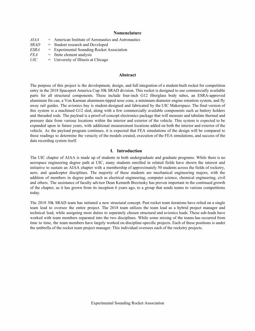
A. Overview Team 65 will compete in the Spaceport America Cup 30k SRAD Division. The rocket, Aptasia (Figure 2), is a 11.25-foot tall, 4-inch diameter vehicle that will launch on an 98mm 6 grain SRAD motor reusing the Aerotech 15360 case. This rocket is 100% identical to the one made by the 30K COTS team. The idea was for the SRAD team to solely focus on the propulsion and have the new members build 2 rockets to gain experience. The expected apogee is 25,000 feet. The avionics section incorporates a dual redundant system built around two Stratologger CF altimeters. Each of these altimeter systems is completely independent. The body tubes are filament wound G12 fiberglass, and the nosecone is a fiberglass Von Karman 5.5:1 with an aluminum tip. The fins are ESRA-approved and commercially produced by MaxQ Binder Design. They are a three-fin aluminum system which is held to the motor casing via pressure applied by 27 bolts, in addition to support form the aft casing closure. As shown in Figure 2, the nose cone coupler tube contains the tracking system, the forward tube contains the main chute and shock cord.
Experimental Sounding Rocket Association
The coupler tube contains the avionics, and the booster tube contains the drogue chute, shock cord, payload, engine retention system, and motor.
Figure 2: Overview of fully loaded rocket vehicle.
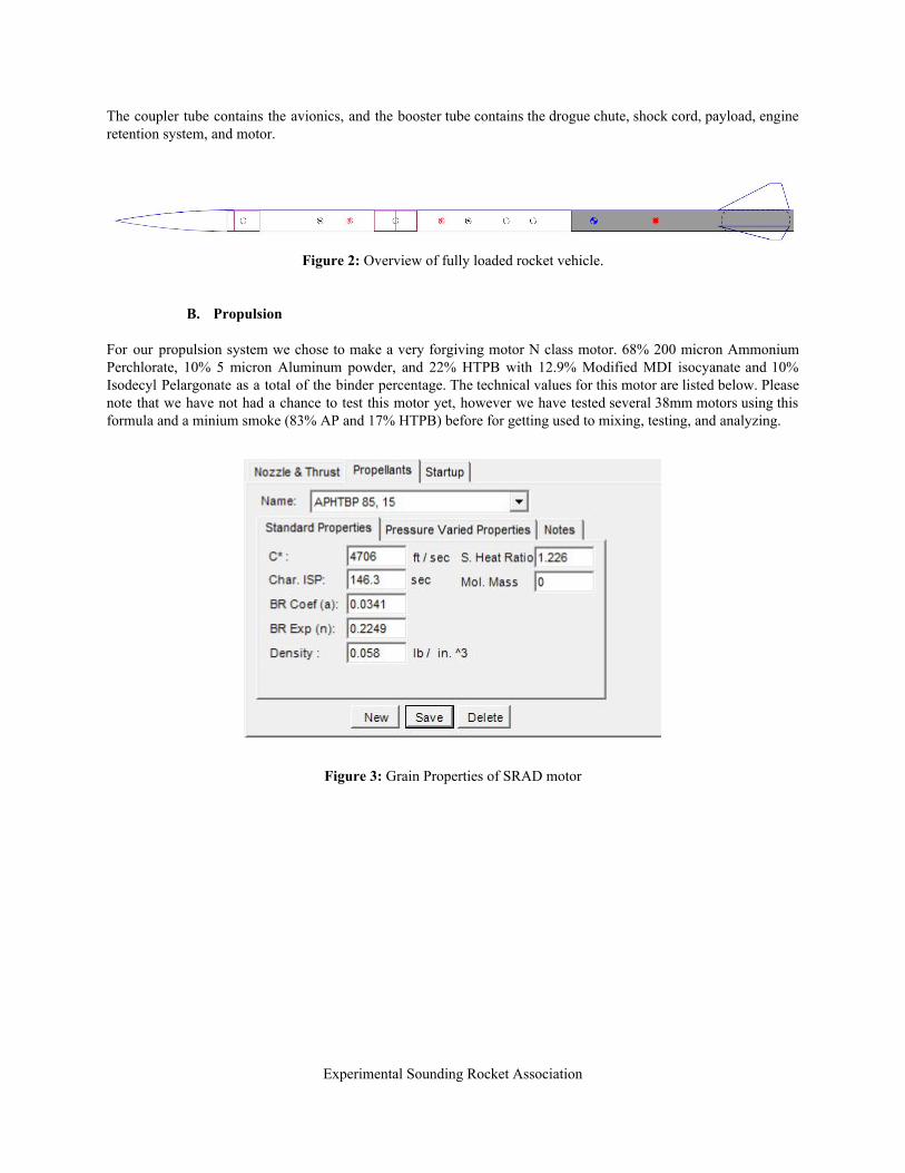
B. Propulsion For our propulsion system we chose to make a very forgiving motor N class motor. 68% 200 micron Ammonium Perchlorate, 10% 5 micron Aluminum powder, and 22% HTPB with 12.9% Modified MDI isocyanate and 10% Isodecyl Pelargonate as a total of the binder percentage. The technical values for this motor are listed below. Please note that we have not had a chance to test this motor yet, however we have tested several 38mm motors using this formula and a minium smoke (83% AP and 17% HTPB) before for getting used to mixing, testing, and analyzing.
Figure 3: Grain Properties of SRAD motor
Experimental Sounding Rocket Association

Figure 4: Nozzle Properties of SRAD motor
Experimental Sounding Rocket Association

Figure 5: Motor Results of SRAD motor
Figure 6: Grain dimensions of SRAD motor
Experimental Sounding Rocket Association

Figure 7: Thrust curve of SRAD motor
Motor: SRAD N1745 Total Impulse: 14,000 N-Sec. Burn Time: 8 Sec. Class: 36% N Average Thrust: 380 lbs Thrust to weight: 7.00 Average Peak Thrust: 420 lbs Thrust to weight: 7.60 Max Max altitude: 25,500 ft. AGL Weight at take off: 55 pounds
Figure 8: Grain dimensions of SRAD motor
Experimental Sounding Rocket Association

C. Aero-Structures
Initial Choices Component description:
Nose cone: Type: Madcow Rocketry G12 Shape: 5.5:1 Von Karman, Metal tipped Length: 23.0 inches Width: 4 inches Coupler: 6.00 inches, 3.75 inches exposed
Upper Airframe tube: Type: Madcow Rocketry G12 Outside Diameter: 4.024 Inside Diameter: 3.900 Length: 30 inches
Booster airframe tube: Type: Madcow Rocketry G12 Outside Diameter: 4.024 Inside Diameter: 3.900 Length: 60 inches
Motor mount: Type: Aeropack Size: 98mm
Fins: Type: MaxQ Dimensions: See figure (13 Appendix 2.6.2.11)
Launch guide: Type: Flyaway Material: 3D printed carbon infused Spring mechanism: Rubber band
Figure 9: Initial design choices for structural components
Center of pressure: 100 inches from tip of nose cone Center of gravity: 85 Inches from tip of nose cone
Initial Design The 30K SRAD decided to make their rocket the exact same as the 30K COTS because we did not have the budget to test two separate rockets. Additionally, we could machine 2 rockets at the same time with the same setup. The results from ejection testing, test flights, and high speed videos would allow us to assume similar behavior with the SRAD rocket. The initial design was very similar to the final version. Although filament wound G12 is not as structurally supportive as carbon fiber and has a higher weight, we decided that these could be compromised for the lowered cost of the material. Since this was a minimum diameter rocket flying on a large motor, we decided to use the commercial MaxQ fin can. Due to a minor error in ordering, we ended up with a fin can that fit over the motor not
Experimental Sounding Rocket Association
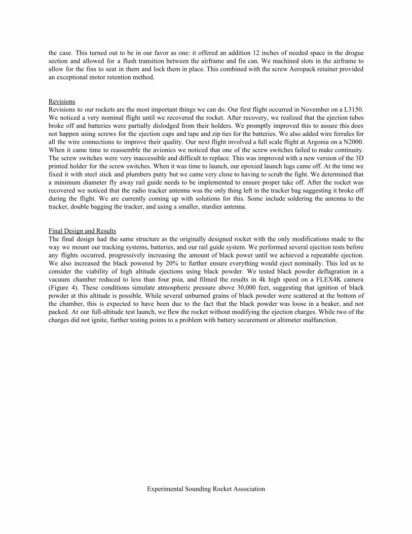
the case. This turned out to be in our favor as one: it offered an addition 12 inches of needed space in the drogue section and allowed for a flush transition between the airframe and fin can. We machined slots in the airframe to allow for the fins to seat in them and lock them in place. This combined with the screw Aeropack retainer provided an exceptional motor retention method. Revisions Revisions to our rockets are the most important things we can do. Our first flight occurred in November on a L3150. We noticed a very nominal flight until we recovered the rocket. After recovery, we realized that the ejection tubes broke off and batteries were partially dislodged from their holders. We promptly improved this to assure this does not happen using screws for the ejection caps and tape and zip ties for the batteries. We also added wire ferrules for all the wire connections to improve their quality. Our next flight involved a full scale flight at Argonia on a N2000. When it came time to reassemble the avionics we noticed that one of the screw switches failed to make continuity. The screw switches were very inaccessible and difficult to replace. This was improved with a new version of the 3D printed holder for the screw switches. When it was time to launch, our epoxied launch lugs came off. At the time we fixed it with steel stick and plumbers putty but we came very close to having to scrub the fight. We determined that a minimum diameter fly away rail guide needs to be implemented to ensure proper take off. After the rocket was recovered we noticed that the radio tracker antenna was the only thing left in the tracker bag suggesting it broke off during the flight. We are currently coming up with solutions for this. Some include soldering the antenna to the tracker, double bagging the tracker, and using a smaller, sturdier antenna. Final Design and Results The final design had the same structure as the originally designed rocket with the only modifications made to the way we mount our tracking systems, batteries, and our rail guide system. We performed several ejection tests before any flights occurred, progressively increasing the amount of black power until we achieved a repeatable ejection. We also increased the black powered by 20% to further ensure everything would eject nominally. This led us to consider the viability of high altitude ejections using black powder. We tested black powder deflagration in a vacuum chamber reduced to less than four psia, and filmed the results in 4k high speed on a FLEX4K camera (Figure 4). These conditions simulate atmospheric pressure above 30,000 feet, suggesting that ignition of black powder at this altitude is possible. While several unburned grains of black powder were scattered at the bottom of the chamber, this is expected to have been due to the fact that the black powder was loose in a beaker, and not packed. At our full-altitude test launch, we flew the rocket without modifying the ejection charges. While two of the charges did not ignite, further testing points to a problem with battery securement or altimeter malfunction.
Experimental Sounding Rocket Association
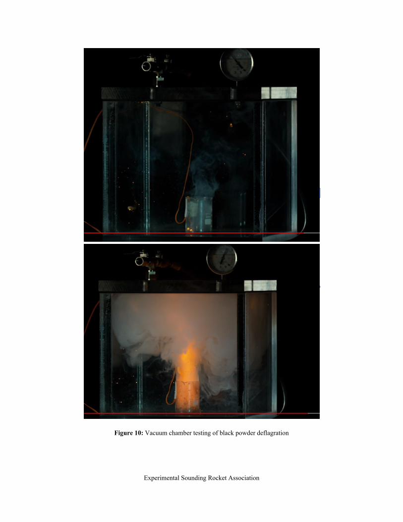
Figure 10: Vacuum chamber testing of black powder deflagration
Experimental Sounding Rocket Association
D. Recovery
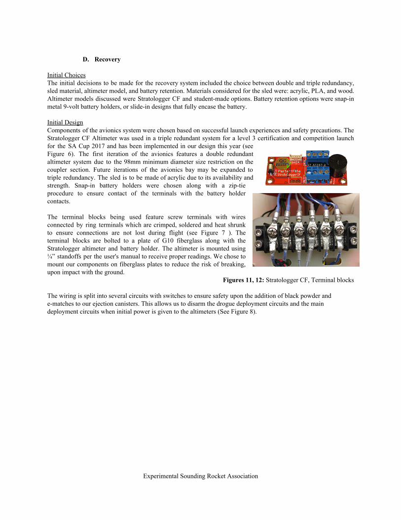
Initial Choices The initial decisions to be made for the recovery system included the choice between double and triple redundancy, sled material, altimeter model, and battery retention. Materials considered for the sled were: acrylic, PLA, and wood. Altimeter models discussed were Stratologger CF and student-made options. Battery retention options were snap-in metal 9-volt battery holders, or slide-in designs that fully encase the battery. Initial Design Components of the avionics system were chosen based on successful launch experiences and safety precautions. The Stratologger CF Altimeter was used in a triple redundant system for a level 3 certification and competition launch for the SA Cup 2017 and has been implemented in our design this year (see Figure 6). The first iteration of the avionics features a double redundant altimeter system due to the 98mm minimum diameter size restriction on the coupler section. Future iterations of the avionics bay may be expanded to triple redundancy. The sled is to be made of acrylic due to its availability and strength. Snap-in battery holders were chosen along with a zip-tie procedure to ensure contact of the terminals with the battery holder contacts.
The terminal blocks being used feature screw terminals with wires connected by ring terminals which are crimped, soldered and heat shrunk to ensure connections are not lost during flight (see Figure 7 ). The terminal blocks are bolted to a plate of G10 fiberglass along with the Stratologger altimeter and battery holder. The altimeter is mounted using ¼” standoffs per the user's manual to receive proper readings. We chose to mount our components on fiberglass plates to reduce the risk of breaking, upon impact with the ground.
Figures 11, 12: Stratologger CF, Terminal blocks
The wiring is split into several circuits with switches to ensure safety upon the addition of black powder and e-matches to our ejection canisters. This allows us to disarm the drogue deployment circuits and the main deployment circuits when initial power is given to the altimeters (See Figure 8).
Experimental Sounding Rocket Association

Figure 13: Altimeter connection diagram The drogue chute is chosen as a 24-inch Cert-3 parachute, and is deployed at apogee, with the backup charge set for apogee plus one second. The payload will also deploy at apogee, and is tethered to the drogue shock cord. The main chute is a 60 inch Recon Recovery, and will deploy at 1,000 feet, with the backup charge set to 850 feet. Decoupling To determine how much black powder would be needed for successful decoupling and ejection of the main and drogue parachute, several known equations were put to use. The rocket was then subjected to ground ejection testing with the calculated values. The following equations are used:
P = AF (1)
where P is pressure, F is force, and A is the effective area.
V = 4πD L2
(2) where V is volume, D is tube diameter, and L is length.
N = P ·V5.16e−4 (3)
where N is the amount of black powder in grams.
Experimental Sounding Rocket Association

It was calculated that 3.25 grams of 4F black powder is needed for successful decoupling. The ground tests performed suggested that while this amount of black powder decoupled the sections most of the time, instances occurred in which full separation was not observed. After an increase to 3.5 grams of black powder, full separation was observed each time. In the interests of the application of a safety factor, this was increased to 4.0 grams for the primary charges, and 4.5 grams for the backup charges.
The ejection system features two bulk-plates, four ejection canisters, two screw terminal blocks, two U-bolts and two aviation connectors. Every component is mounted to its respective bulk-plate with bolts. The ejection canisters are mounted with slow-cure epoxy and are also bolted down so that they do not break off upon impact with the ground. The use of the aviation connectors allows wires to go through the bulk-plate while maintaining pressure in the payload and booster sections to assist with ejection.
Main recovery: Parachute type: Parachute size: Number of lines: Harness: ½ inch Kevlar strap. 7600lb rating
Drogue recovery: Parachute type: Recon Parachute size: 24 inches Harness: ½ inch Kevlar strap, 60 feet, 7600lb rating.
Avionics bay: Type: Madcow Rocketry G12 Outside Diameter: 3.899 inches Inside Diameter: 3.755 inches Length: 12 inches Bulkheads: 0.178 inch G10 with 0.089 inch recessed inside lip
Flight computers Primary :Stratologger CF Backup: Stratologger CF
Switches: Fight computers: 6-32 Screw switches Deployment charges: 6-32 Screw switches
Figure 14: Initial design choices for recovery components
Revisions Two significant revisions to the recovery system have been completed. First, the oversized and overly complicated 96” main chute was brought down to a 60” chute that will provide an acceptable descent rate, which decreasing the number of shroud lines and increasing ease of packability. Additionally, the switch plate mounting brackets were re-designed to present a lower profile inside the coupler tube. All other geometries were maintained. A mistake in execution has also been identified and remedied. The initial plate was to include slots next to the battery holder for zip ties, present to ensure the batteries stayed in place during flight. The initial printings did not include these slots, and they were added thereafter.
Experimental Sounding Rocket Association

Final Design and Results The final version is a sled system very similar to the initial design. Some functional enhancements have been implemented, as described in the Revisions section. This system has seen two test flights and multiple ground tests. With the upgrades performed, and increased testing scrutiny before flight, we are confident in the performance of the system at competition.
E. Payload
Initial Choices Microcontroller: Arduino Nano Data Storage: Adafruit SD Card Breakout Board Temperature Sensors: BMP180 Barometric Pressure Sensor Battery: Disposable 9V Initial Design The initial design was a simple data logger to be used as a proof of concept for more advanced telemetry and data gathering. Having a basic system working in a stable and reliable manner is important before adding more functionality. The goal of this design was to work out as many bugs as possible from the Sensor > Arduino > SD Card system. The interface between the SD card and Arduino is very low-level and does not have the safeguards built into it that would normally be seen in a more sophisticated system such as a smartphone. This leaves us with the burden of making sure all writes are safe and will not corrupt the SD card, which would prevent any further data logging. Revisions No revisions to this system have been introduced. The payload system had been only ballast until March, when ESRA pointed out that boilerplate mass payloads carried by rockets under 5.5 inches in diameter were in violation of the payload geometry rules. Since that time, a simple system has been conceived of and developed, with assembly ongoing. Minor revisions may occur in the weeks between report due date and competition launch, but they will almost certainly be minor in scope, as large-scale revisions would likely push the timetable too far for launch at Spaceport America. Final Design and Results Our final design will be a more polished and compact version of our initial design. Using custom PCBs printed at our Makerspace on campus, we can make the datalogger very compact and low-profile.
III. Mission Concept of Operations Overview IV.
A. Phase 1: Assembly
The first phase is the assembly of the rocket vehicle. Assembly is performed by following the system-specific assembly checklist. Assuming approval has been given by the RSO of ESRA and all other checks have been performed, all of the subsystems are grouped together and inspected before final approval from the system and team leads. This phase includes checking the avionics for continuity, disarming the screw switches, and loading the black powder. Full assembly of the subsystems into the vehicle is the last step before continuing to the phase two.
B. Phase 2: Approval
Experimental Sounding Rocket Association

The approval phase begins when the vehicle is taken to the judges to be inspected for stable flight. All flight cards and paperwork should be approved and filed before walking out onto the range. Phase two also assures that nothing is forgotten or missed. This includes, but is not limited to: ensuring all necessary hardware is accounted for; Igniters, sticks, tape, extra switch screws, extra shear pins, extra mounting screws, extra screwdrivers, extra fly away rail guides, lubrication for the rail, sandpaper etc. It is important to know that phase two cannot be completed unless there are at least two range-designated team members who will carry the materials listed above.
C. Phase 3: Transport The transport phase includes the transport and loading of the vehicle onto the rail. The rocket will be loaded onto a vehicle that is designated to drive the rocket to the rail. This phase will include three people: the diver and and two range-designated members responsible for loading the rocket on the rail. After the rocket is unloaded by the two range-designated personnel, they will walk over to the rail and place the rocket on the ground and wait until they are given permission to load the rocket on the rail. After loading, the rocket will be uprighted and, the avionics will be turned on and the ejection charges will be armed. This is done by placing the switch screws into the respective switches, and tightening them until the appropriate altimeter beeps are audible. This will be repeated for all the avionics and ejection charges. Next, the igniter will be taped onto a stick and the wire wrapped around to ensure no strain on the igniter. The igniter will be inserted through the nozzle until it reaches the top of the motor. The stick will be taped to the nozzle and the alligator clips will be securely fastened to the bare wire of the igniter. One last continuity check and check of the igniter and completion of the preflight checklist of the will mark the end of phase three. Personnel will then depart the launch area, and await RSO clearance before the initiation of the ignition phase.
D. Phase 4: Ignition After launch is approved by the RSO, the launch button is pressed, and an electrical signal is sent to the igniter. The motor will ignite and begin to pressurize. This will be visible by smoke and fire coming from the aft section of the rocket.
E. Phase 5: Liftoff The liftoff phase begins once the motor has fully pressurized, and the rocket begins to move vertically. The on board computers will sense the change in acceleration and being sampling and checking onboard performance.
F. Phase 6: Powered Flight The rocket will now be in motion. Once the rail guides fully leave the rail and detach from the rocket, the rocket will continue until motor burnout. This phase will last approximately 8 seconds.
G. Phase 7: Unpowered Flight After motor burnout, the rocket will coast in its unpowered flight towards apogee. At this point, the onboard systems should have confirmed the successful transition between these two phases by sensing the change in acceleration. The rocket will maintain a positive vertical velocity for approximately 35 seconds after liftoff. As the vehicle approaches apogee, the alitemters and payload will sense the barometric pressure as semi steady and will begin the deployment protocol.
H. Phase 8: Deployment Once the altimeters sense steady barometric pressure, the primary altimeter will deploy the primary charge followed, one second later, by deployment via the backup altimeter. This will pressurize the body tube and shear the plastic screws holding the aft airframe to the avionics coupler. The deployment phase ends when the shock cords, drogue parachute, and payload are pulled from the vehicle body.
I. Phase 9: Descent Descent begins as the drogue parachute begins to inflate, and the two sections of the airframe will begin their descent. This phase is designed for a quick, stable descent, and to prevent the rocket from coming in ballistic. This
Experimental Sounding Rocket Association

phase is expected to take several minutes. The altimeters will monitor the altitude until a predetermined level is reached for secondary deployment.
J. Phase 10: Secondary Deployment Once the altimeters sense the pressure corresponding to the predetermined altitude, the primary altimeter will ignite the primary charge, followed by the secondary charge 150 feet below the primary. This will once again pressurize the tube, and shear the plastic screws holding the forward airframe with the nose cone. The shock cords and main parachute will be pulled from the body, signalling the end of phase 10.
K. Phase 11: Secondary Descent The secondary descent phase begins as the main parachute begins to inflate and significantly reduce the descent rate to about 20 feet per second. The secondary descent phase is expected to take approximately one minute, and concludes with touchdown
L. Phase 12: Touchdown As the rocket is coming down on the main parachute, it will begin to get closer to the ground. Since the parachute suspends the airframe with the aft section being the lowest, that section will make first contact followed by the forward section and payload, and finally the nose cone. Touchdown is complete when all sections have made contact with the ground.
M. Phase 13: Recovery Once the rocket has successfully landed, the recovery team will be deployed to start searching for the rocket using the on-board GPS and radio trackers. When they make visual contact, they will asses for any damage, any sections that may not have separated, and for any ejection charges that may have not deployed. If all was nominal, the team will disarm the spent ejection charges and turn the altimeters off and gather the parts for transport. In the event that an ejection failed to occur, a section failed to separate, or other significant damage, the team will follow emergency procedures and document the failure.
Experimental Sounding Rocket Association
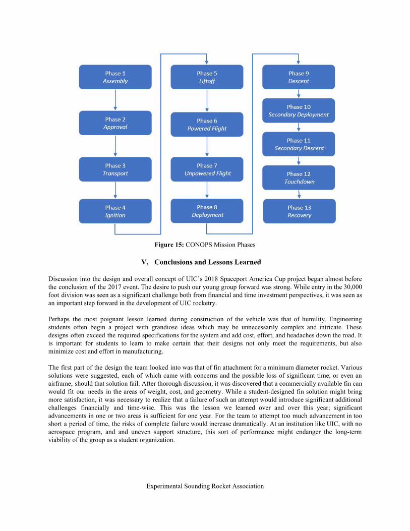
Figure 15: CONOPS Mission Phases
V. Conclusions and Lessons Learned
Discussion into the design and overall concept of UIC’s 2018 Spaceport America Cup project began almost before the conclusion of the 2017 event. The desire to push our young group forward was strong. While entry in the 30,000 foot division was seen as a significant challenge both from financial and time investment perspectives, it was seen as an important step forward in the development of UIC rocketry. Perhaps the most poignant lesson learned during construction of the vehicle was that of humility. Engineering students often begin a project with grandiose ideas which may be unnecessarily complex and intricate. These designs often exceed the required specifications for the system and add cost, effort, and headaches down the road. It is important for students to learn to make certain that their designs not only meet the requirements, but also minimize cost and effort in manufacturing. The first part of the design the team looked into was that of fin attachment for a minimum diameter rocket. Various solutions were suggested, each of which came with concerns and the possible loss of significant time, or even an airframe, should that solution fail. After thorough discussion, it was discovered that a commercially available fin can would fit our needs in the areas of weight, cost, and geometry. While a student-designed fin solution might bring more satisfaction, it was necessary to realize that a failure of such an attempt would introduce significant additional challenges financially and time-wise. This was the lesson we learned over and over this year; significant advancements in one or two areas is sufficient for one year. For the team to attempt too much advancement in too short a period of time, the risks of complete failure would increase dramatically. At an institution like UIC, with no aerospace program, and and uneven support structure, this sort of performance might endanger the long-term viability of the group as a student organization.
Experimental Sounding Rocket Association

At the beginning of this school year, the UIC AIAA chapter was moved from our long-time home to a much smaller, subdivided space. We did not have access to a room with sufficient square footage rocket development and construction until midway through the first semester. At the conclusion of this school year it was announced that we would be forced to move once again. We have recently been notified that this future location will likely not be ours for very long, either. The lesson from these experiences is clear; change is inevitable. If our teams are unable to stay on track through these environmental changes, there would be little hope for success. An additional challenge faced this year was that of the partial failure of the avionics system at our most recent test launch. It is clear that too much confidence was placed in a commercial product and previous testing. This was a difficult lesson to bear the results of, as we were hoping for a fully successful launch to build confidence heading into Spaceport America Cup. That being said, this was likely a blessing in disguise, as we now have procedures in place to perform both continuity testing, and altimeter testing on-site, directly before lunch. The group has long struggled with the passage of knowledge and lessons learned to future upperclassmen. Documentation and project outcomes have often been lost in the shuffle. This has resulted in most new groups being forced to begin development of their projects almost from the ground up. The 2018 Spaceport America Cup team has concentrated heavily on documentation, and has also begun including younger members in the higher-level procedural, and design decisions that may have been done without their knowledge in the past. A google drive has been created and organized with growth in mind. Documents have been produced detailing duties and expectations of the various management and lead positions within the rocketry group. It is our hope that this will serve to increase the involvement and understanding of the younger members.
Experimental Sounding Rocket Association

Appendix A: System Weights, Measures, and Performance Data
Experimental Sounding Rocket Association

Experimental Sounding Rocket Association
Experimental Sounding Rocket Association

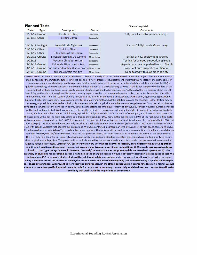
Appendix B: Project Test Reports Recovery System Testing The recovery system has undergone a wide range of testing, from initial continuity and ejection ground testing, to multiple in-flight tests. While some issues have been found. Rigorous continued tests of both wiring and new altimeters are expected to confirm confidence in system functionality before launch at Spaceport America. Table 1 details these past and future tests.
Table 1: Recovery system testing log
Date Type Status Notes
11/1/17 Ejection Testing Successful
11/19/17 Low-Altitude Flight Successful
Experimental Sounding Rocket Association

1/29/18 Vacuum Chamber Test of Black Powder Deflagration
Successful Standard black powder deflagration procedures found to be acceptable to
30,000 feet
3/11/18 Full-Altitude Flight Minor Issues Altimeter issues found. Direct pre-flight altimeter
checks initiated for all successive flights.
5/30/18 Expected Continuity and Ejection Testing
Pending
The avionics bay sled consists of two identical plates, and is shown in Figure 11 (Battery used as placeholder only. Launch operations use only Duracell Procell 9V batteries, checked for voltage). Each plate contains a completely independent system of battery, Stratologger CF altimeter, and respective wiring. The two plates are situated back to back, with a gap of approximately 0.5 inches between them. This allows the wires to be fed through each plate into the gap for more efficient cable management. The wires are also color coded such that a simple visual check allows for identification of a particular wire’s function and destination. Terminal blocks are used for easy connection and disconnection. As wires exit the dual plate sled, they are grouped by destination and bundled. Aviation connectors are used to pass the wires through the bulkheads. Prior to this, each circuit needs to be completed by closing a screw switch on the exterior of the coupler band. There are three screw switches for each plate: drogue arming switch, main arming switch, and battery switch. Each of these switches remains open and ‘turned off’ until the rocket is on the launch pad, and the RSO has approved the arming of pyrotechnics.
Experimental Sounding Rocket Association

Figure 16: Avionics sled design, plate one of two.
Experimental Sounding Rocket Association
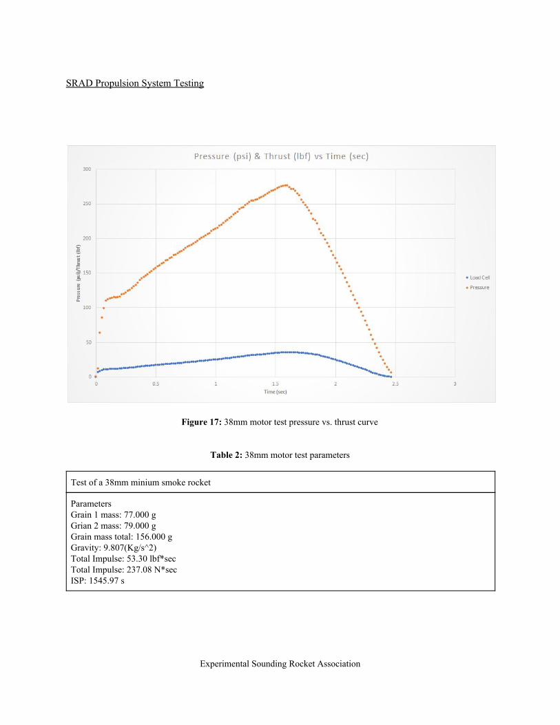
SRAD Propulsion System Testing
Figure 17: 38mm motor test pressure vs. thrust curve
Table 2: 38mm motor test parameters
Test of a 38mm minium smoke rocket
Parameters Grain 1 mass: 77.000 g Grian 2 mass: 79.000 g Grain mass total: 156.000 g Gravity: 9.807(Kg/s^2) Total Impulse: 53.30 lbf*sec Total Impulse: 237.08 N*sec ISP: 1545.97 s
Experimental Sounding Rocket Association

Figure 18: 38mm motor test fire
Figure 19: Minimum Smoke propellant
Experimental Sounding Rocket Association

Figure 20: Aluminized propellant
Figure 21: research igniter
Experimental Sounding Rocket Association

Figure 22: research igniter
These igniters have been one of the most reliable we have ever made. These slow motion videos helped us calculate the velocity of the burning magnesium, spin, and splatter for the most efficient ignition.
Experimental Sounding Rocket Association

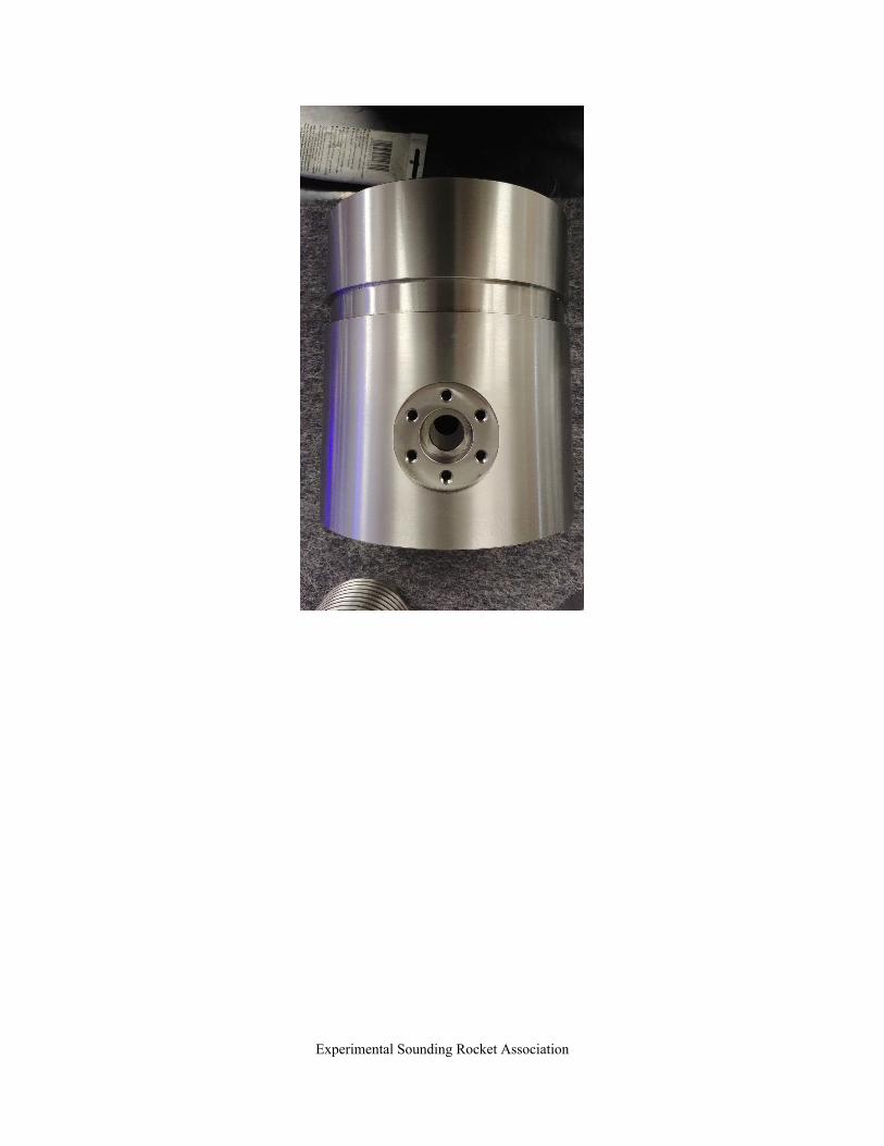
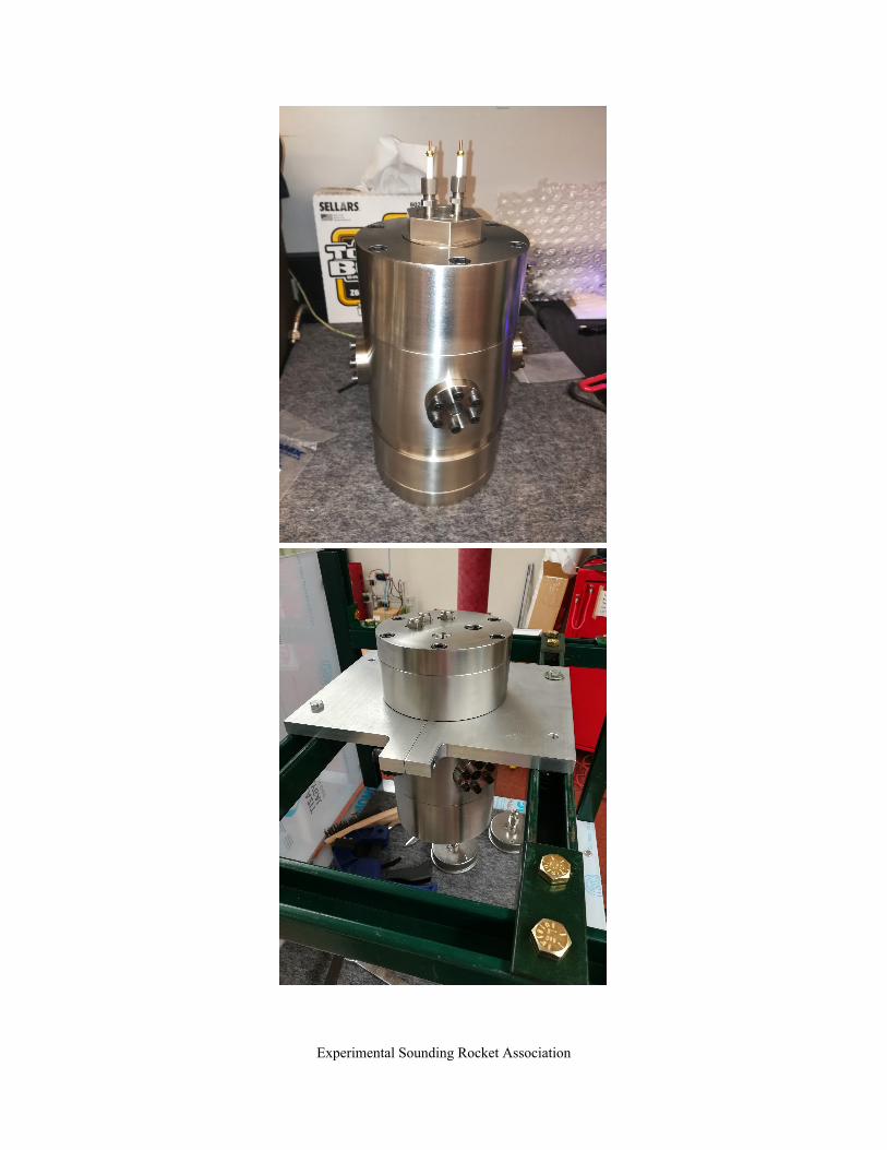
SRAD Pressure Vessel Testing A Strand Burner has been in development by the SRAD team in order to fully characterized the current propellant used. Hydrostatic testing of the system is expected to occur on 06/20/2018, with an expected completion date of 06/29/2018. Due to the late completion date, the SRAD team has conducted various empirical tests shown in the section SRAD Propulsion Systems Testing. The strand burner itself will have the ability to characterize the burn rate of a strand of the SRAD propellant under various pressures. The chamber itself if designed with a 10x safety factor, with multiple redundancies and backup systems in play to mitigate any and all failure modes. The strand burner consists of a main pressurized chamber, windows to measure the burn rate, a secondary vessel to dampen the chamber pressure increase during testing, and electrodes to remotely ignite the propellant strand.
Experimental Sounding Rocket Association

Experimental Sounding Rocket Association
Experimental Sounding Rocket Association
Experimental Sounding Rocket Association

Figure 23, 24, 25, 26, 27, 28, 29: Pictures of machined vessel
Experimental Sounding Rocket Association

Figure 30: Relay safety schematic. This is used to assure any electrical issues in the control or system will not allow
unwanted flow through the system. Additionally, LabView is used to control the system with a relay safety system, Figure 30, designed to assure no unwanted flow occurs through the system. The SRAD team is hoping to use this strand burner in future iterations of the SRAD competition in order to fine tune the propellant developed for maximum efficiency. The Strand Burner will be used for developing newer solid propellants by recording burn rate data at different pressure conditions. We would be using the strand burner for analysing heat transfer rates from the system to the surrounding and mitigating better combustion chamber design to minimize losses due to thermal heat transfer. Using the strand burner test and analysing combustion products formed and determining the chemical kinetic rate of product formation to increase efficiency of the combustion process. Using Laser spectroscopy to study the flame temperatures, ignition delays and Chemical mechanisms of the combustion reaction.
Experimental Sounding Rocket Association

Appendix C: Hazard Analysis As Team 65 will compete in the 30k SRAD division, the risks associated with hazardous material transportation and usage are minimized. All motors will be transported to the site in a fully disassembled state, in-box from the manufacturer. Likewise, black powder will be transported in its original commercial packaging, then placed in military grade ammo can, and will only be measured and placed into the coupler ejection canisters on-site just before the pre-launch RSO check. As no other energetics are to be used for the project, additional hazards are considered negligible.
Appendix D: Risk Assessment Analysis
Hazard Possible Causes Risk of Mishap and Rationale
Mitigation Approach
Risk of Injury after Mitigation
Explosion of solid-propellant rocket motor during launch with blast of flying debris causing injuries
-Crack in the grains of the motor -Debonding of propellant from inside of liner -Incorrect assembly of the motor -Motor end closures fail to hold
Low; commercial motor assembled by experienced students
-Ensure proper commercial casing is being used -Visually inspect motor grain for cracks, debonds, and gaps during and after assembly -Oly essential personnel in launch crew -Launch crew 200 feet from rocket at launch, behind barrier (vehicle)
Low
Rocket deviates from nominal flight path and comes into contact with personnel at high speed
-Instability -Wind knocks over the launch rail -Launch buttons get stuck on the rail
Low; Rails to be inspected prior to launch. Simulations provide strong evidence that stability of 1.5+ at rail departure.
-Visual inspection of launch rail before attaching rocket -Inspection of rail buttons for excess flashing or debris -Launch crew 200 feet from rocket at launch, behind barrier (vehicle)
Low
Recovery system fails to deploy and rocket or payload comes into contact with personnel
-Failure of primary or backup charges -Shock cord failure -Altimeter malfunction
-Low to medium; avionics system is double redundant. New commercial altimeters to be used for launch, and
-Continuity testing on-site -Altimeter testing on-site
Low
Experimental Sounding Rocket Association

thorough continuity and altimeter testing to be performed during competition prep.
Recovery system partially deploys, rocket or payload comes into contact with personnel
-Improper assembly of motor -Failure of primary or backup charges -Shock cord failure -Altimeter malfunction
-Low to medium; avionics system is double redundant. New commercial altimeters to be used for launch, and thorough continuity and altimeter testing to be performed during competition prep.
-Continuity testing on-site -Altimeter testing on-site
Low
Recovery systems deploys during assembly or pre launch causing injury
Altimeter malfunction
Low; New altimeters
- Inspect altimeters - Set at proper deployment altitude - Check continuity between battery altimeter and switches
Low
Rocket does not ignite when command is given (“hang fire”), but does ignite when team approaches to troubleshoot
Commercial/ hand-made igniters was defective or damaged prior to set-up
Low: Igniters have hot composition and will most likely light entirely or not at all. Medium risk for handmade igniters; student build with thorough testing
- Inspect igniter prior to use - Wait several minutes to approach the rocket
Low
Rockets falls from launch rail during pre launch preparation, causing injuries
Rail button failure Low; Rail buttons have been inspected and highly tested
Inspect rail button prior to flight
Low
Experimental Sounding Rocket Association
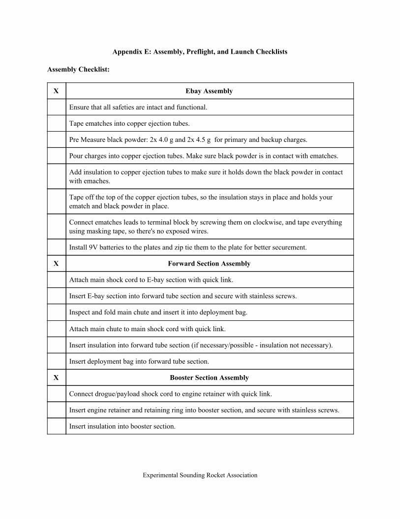
Appendix E: Assembly, Preflight, and Launch Checklists Assembly Checklist:
X Ebay Assembly
Ensure that all safeties are intact and functional.
Tape ematches into copper ejection tubes.
Pre Measure black powder: 2x 4.0 g and 2x 4.5 g for primary and backup charges.
Pour charges into copper ejection tubes. Make sure black powder is in contact with ematches.
Add insulation to copper ejection tubes to make sure it holds down the black powder in contact with emaches.
Tape off the top of the copper ejection tubes, so the insulation stays in place and holds your ematch and black powder in place.
Connect ematches leads to terminal block by screwing them on clockwise, and tape everything using masking tape, so there's no exposed wires.
Install 9V batteries to the plates and zip tie them to the plate for better securement.
X Forward Section Assembly
Attach main shock cord to E-bay section with quick link.
Insert E-bay section into forward tube section and secure with stainless screws.
Inspect and fold main chute and insert it into deployment bag.
Attach main chute to main shock cord with quick link.
Insert insulation into forward tube section (if necessary/possible - insulation not necessary).
Insert deployment bag into forward tube section.
X Booster Section Assembly
Connect drogue/payload shock cord to engine retainer with quick link.
Insert engine retainer and retaining ring into booster section, and secure with stainless screws.
Insert insulation into booster section.
Experimental Sounding Rocket Association

Connect payload to drogue shock cord with quick link.
Insert payload into booster tube section.
Inspect and fold drogue chute.
Connect drogue chute to drogue shock cord with quick link.
Insert drogue chute into booster tube section.
X Final Assembly
Insert nose cone section into forward tube section and secure with shear pins.
Insert ebay/forward tube section into booster section and secure with shear pins.
Arm and check all altimeters for functionality.
Make sure to tape the igniter to the side of the rocket to ensure we have it while walking towards launchpad.
Launch Pad Checklist:
Slide the rocket on the rail carefully, so you don't damage the rail buttons.
Raise the rocket and check for clearance.
Arm avionics Ebay system by tightening the screw switches.
Insert 2 igniters wrapped around ¼ inch dowel and ensure they are at the top of the motor.
Discharge alligator clips by touching them together.
Use sandpaper to clean clips for better connectivity if they are dirty.
Clip igniter wires; wrap several times around clip for better continuity.
Spread clips apart at least 6 inches or suspend making sure they will not touch each other.
Check continuity before walking off the launch pad.
Experimental Sounding Rocket Association

Arming Checklist:
X Switches (altimeters)
Make sure the shear pins are intact in the ebay tube.
Arm drogue altimeter by turning the screw switches into ON position.
Wait for confirmation “BEEPS”.
Arm main altimeter by turning the screw switches into ON position.
Wait for confirmation “BEEPS”.
Proceed to the ignitor Checklist.
X Ignitor
Wrap two igniters onto a wooden dowel.
Insert the wooden dowel with ignitors through the nozzle, making sure the ignators reach the top of the motor.
Secure the wooden dowel with the nozzle cap provided by the manufacturer.
Connect igniter leads to alligator clamps.
If any aberrant behavior is observed, move to Igniter Failure checklist.
Disarming Checklist:
X Disarming Checklist
If motor ignition fails, wait 5 minutes before approaching the launch pad.
When on launch pad, disconnect the ignition leads form alligator clamps.
Disarm the drouge altimeter by turning the screw switch into OFF position.
Disarm the main altimeter by turning the screw switch into OFF position.
After disarming the controllers, check the igniter and confirm if it went off or not.
X Igniter Failure
Experimental Sounding Rocket Association

After confirming failed igniter, simply replace igniter with a new one.
When installing new igniter, make sure to go through the arming igniter checklist procedure again.
X Altimeter Arming Failure
After completing disarming checklist, take the rocket back to the camp for further inspection.
Uninstall the Ebay section from the rocket.
Take out the batteries from Ebay section and with a voltmeter, check the batteries voltage and make sure it is 9V or above.
When batteries are good, run a continuity check on all the wiring using Perfect Flight program, by ejecting the ematches connected to the altimeters.
Experimental Sounding Rocket Association
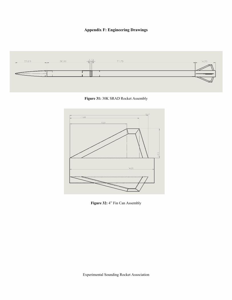
Appendix F: Engineering Drawings
Figure 31: 30K SRAD Rocket Assembly
Figure 32: 4” Fin Can Assembly
Experimental Sounding Rocket Association
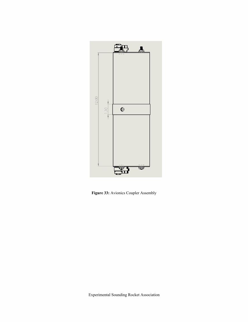
Figure 33: Avionics Coupler Assembly
Experimental Sounding Rocket Association

Figure 35, 36: Avionics sled placement, Acrylic avionics plate design
Experimental Sounding Rocket Association

Figure 37: Avionics plate (one of two) with components
Experimental Sounding Rocket Association

VESSEL drawings
Figure 38: Vessel drawing
Experimental Sounding Rocket Association

Figure 39: Top plate drawing
Experimental Sounding Rocket Association

Figure 40: Bottom cap
Experimental Sounding Rocket Association

Figure 41: Acme Thread drawing
Experimental Sounding Rocket Association

Figure 42: Electrode holder drawing
Experimental Sounding Rocket Association

Figure 43: Window retainer drawing
Experimental Sounding Rocket Association
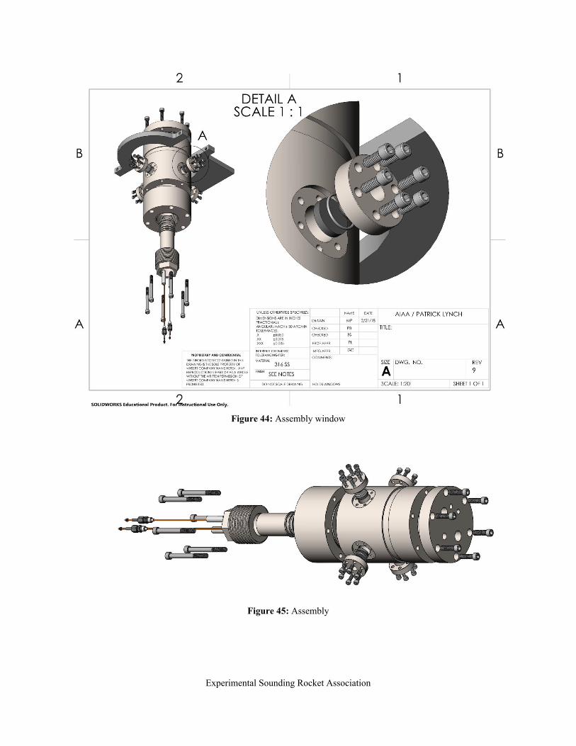
Figure 44: Assembly window
Figure 45: Assembly
Experimental Sounding Rocket Association