teaching of basic photogrammetry - asprs of basic i>hotogrammetry reynold e. ask lecturer in...
TRANSCRIPT
TEACHING OF BASIC I>HOTOGRAMMETRY
Reynold E. AskLecturer in Photogrammetry, George Washington University
I. INTRODUCTION
D URING the past two and one-half years the writer has been instructing aWar Training Course in A~rial Photogrammetry at George Washington
University. The purpose of this article is to discuss the manner in which thecourse was presented with the hope that the information be of some value tothose who may be called upon to teach similar courses in the future. Due to theincrease in the use of aerial photographs for engineering and military purposes,it is most probable that courses in photogrammetry will soon be offered in allprogressive engineering colleges.
The scope of any particular course necessarily will have to be adjusted tofit the needs and qualifications of the students. In this discussion we will assumethat the students are familiar with topographic drafting, trigonometry, andplane surveying, and that they are interested in obtaining a basic knowledge ofthe entire field of aerial photogrammetry, with special emphasis on practicalmap compilation. The order of presentation of the various subjects will be asfollows: Equipment required, suggested course outline, and general textbooks.
I I. EQUIPMENT REQUIRED
Generally speaking, schools starting courses in photogrammetry have a limited budget for equipment. Although the cost of many photogrammetric instruments runs into thousands of dollars, those necessary to teach the basic principlescan be obtained at a reasonable figure. A suggested list of equipment for a Classunit of fifteen students will be given, together with the approximate cost of eachitem. A list of known manufacturers of these instruments will be found at the endof this section.
Many of the instruments to be included in this discussion are used extensively by the armed forces, and therefore are rather difficult to obtain at thepresent time. Even with a high priority rating, the purchaser may have to waitmonths for delivery. For this reason, suggestions are given on substitute equipment which can be constructed in any school workshop and which require theuse of very little critical material.
LENS STEREOSCOPES (15 required)
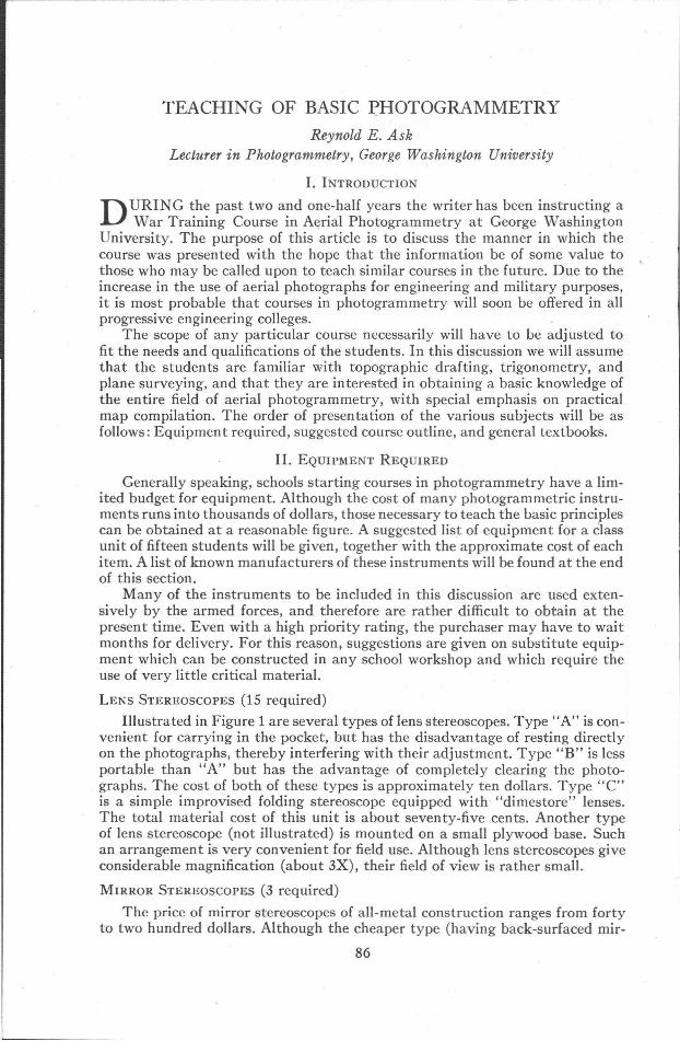
Illustrated in Figure 1 are several types of lens stereoscopes. Type "A" is convenient for carrying in the pocket, but has the disadvantage of resting directlyon the photographs, thereby interfering with their adjustment. Type "B" is lessportable than "A" but has the advantage of completely clearing the photographs. The cost of both of these types is approximately ten dollars. Type "C"is a simple improvised folding stereoscope equipped with "dimestore" lenses.The total material cost of this unit is about seventy-five cents. Another typeof lens stereoscope (not illustrated) is mounted on a small plywood base. Suchan arrang.ement is very convenient for field use. Although lens stereoscopes giveconsiderable magnification (about 3X), their field of view is rather small.
MIRROR STEREOSCOPES (3 required)
The price of mirror stereoscopes of all-metal construction ranges from fortyto two hundred dollars. Although the cheaper type (having back-surfaced mir-
86
TEACHING OF BASIC PHOTOGRAMMETRY
FIG. 1. Types of lens stereoscopes. (A) Folding pocket model. (B)Desk model which completely clears the photographs. (C) Improvisedwood model.
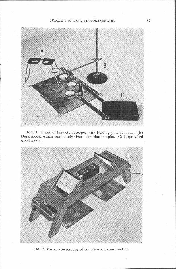
FIG. 2. Mirror stereoscope of simple wood construction.
87
88 PHOTOGRAMMETRIC ENGINEERING
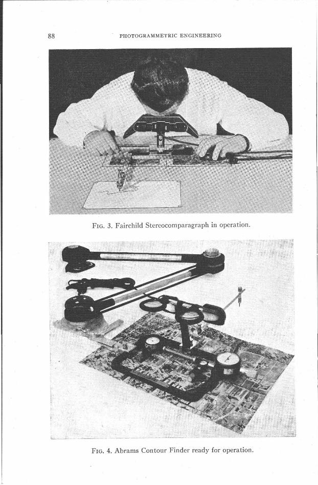
FIG. 3. Fairchild Stereocomparagraph in operation.
. .
~_....__._..:..._.__·_1
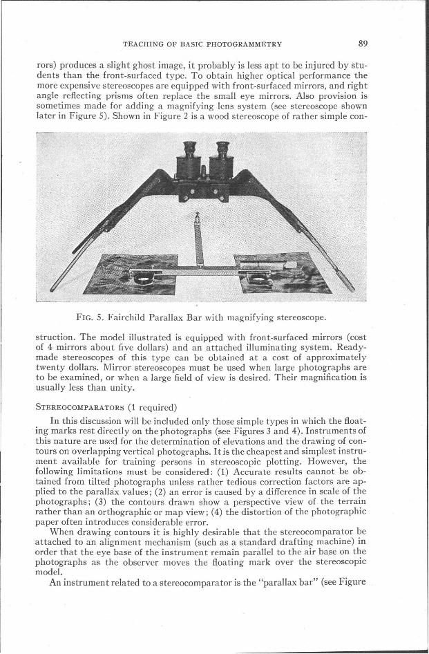
FIG. 4. Abrams Contour Finder ready for operation.
TEACHING OF BASIC PHOTOGRAMMETRY 89
rors) produces a slight ghost image, it probably is less apt to be injured by students than the front-surfaced type. To obtain higher optical performance themore expensive stereoscopes are equipped with front-surfaced mirrors, and rightangle reflecting prisms often replace the small eye mirrors. Also provision issometimes made for adding a magnifying lens system (see stereoscope shownlater in Figure 5). Shown in Figure 2 is a wood stereoscope of rather simple con-
FIG. 5. Fairchild Parallax Bar with magnifying stereoscope.
struction. The model illustrated is equipped with front-surfaced mirrors (costof 4 mirrors about five dollars) and an attached illuminating system. Readymade stereoscopes of this type can be obtained at a cost of approximatelytwenty dollars. Mirror stereoscopes must be used when large photographs areto be examined, or when a large field of view is desired. Their magnification isusually less than unity.
STEREOCOMPARATORS (1 required)
In this discussion will be included only those simple types in which the floating marks rest directly on the photographs (see Figures 3 and 4). Instruments ofthis nature are used for the determination of elevations and the drawing of contours on overlapping vertical photographs. I t is the cheapest and simplest instrument available for training persons in stereoscopic plotting. However, thefollowing limitations must be considered: (1) Accurate results cannot be obtained from tilted photographs unless rather tedious correction factors are applied to the parallax values; (2) an error is caused by a difference in scale of thephotographs; (3) the contours drawn show a perspective view of the terrainrather than an orthographic or map view; (4) the distortion of the photographicpaper often introduces considerable error.
When drawing contours it is highly desirable that the stereocomparator beattached to an alignment mechanism (such as a standard drafting machine) inorder that the eye base of the instrument remain parallel to the air base on thephotographs as the observer moves the floating mark over the stereoscopicmodel.
An instrument related to a stereocomparator is the "parallax bar" (see Figure
90 PHOTOGRAMMETRIC ENGINEERING
5) or "tracing stereometer." This is a parallax measuring device similar to thefloating mark assembly on the above stereocomparators. It can be used withalmost any mirror stereoscope, thus keeping the cost of the complete unit to aminimum. l The cost of a stereocomparator (also called stereocomparagraph orcontour finder) ranges from 250 to 300 dollars. Drafting machines to use withthese instruments cost from forty to ninety dollars. The cost of a parallax bar isabout eighty dollars. In case a stereocomparator cannot be obtained, it is stillpossible to instruct students in the theory and practice of parallax measurements with no more equipment than a twelve-inch engineer's scale (see sectionIII, item 11).
SPIDER TEMPLETS (75 units-optional)
Various names such as radial intersectors,2 slotted mechanical templets, andmechanical triangulators have been used to describe this equipment. For instructional purposes in radial triangulation, these metal templets have several advantages over other templet systems (see section III, item 8). since they can beused repeatedly without any material loss. The cost of 75 complete units (for9" X9" photographs) including arms, bolts, nuts, studs, and pins is approximately seventy-five dollars.
REFLECTING PROJECTORS (one-optional)
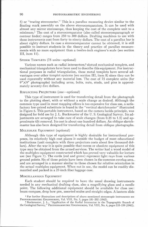
This type of instrument is used for transferring detail from the photographto the plotting sheet, with or without a scale change as desired. Although thecommon type used in most mapping offices is too expensive for class use, a satisfactory low-priced substitute is found in the "vertical sketchmaster" illustratedin Figure 6. This portable instrument, based on the camera lucida principle, wasdesigned for field use by J. L. Buckmaster of the U. S. Geological Survey. Its adjustments are arranged to take care of scale changes (from 0.25 to 1.5) and approximate tilt removal. Its cost is about one hundred dollars. An oblique sketchmaster has also been designed for transferring detail from oblique photographs.
MULTIPLEX EQUIPMENT (optional)
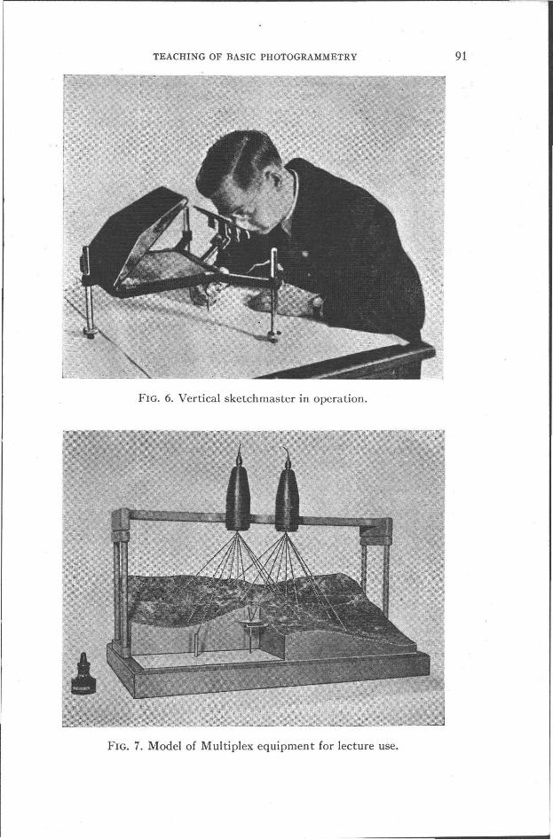
Although this type of equipment is highly desirable for instructional purposes, its relatively high cost places it outside the budget of most educationalinstitutions (unit complete with three projectors costs about five thousand dollars). After the war it is quite possible that excess or obsolete equipment of thistype may be obtained from the armed services. The writer had a wood model ofthe multiplex equipment constructed which has proved very valuable for lectureuse (see Figure 7). The cords (red and green) represent light rays from variousground points. Six of these points have been chosen in the common overlap area,and are arranged in a manner similar to those chosen for relative orientation inthe actual multiplex equipment. When not in use, the model can be readily dismantled and packed in a 27-inch fiber luggage case.
MISCELLANEOUS EQUIPMENT
Each student should be required to have the usual drawing instrumentsneeded in any mechanical drafting class, also a magnifying glass and a needlepoint. The following additional equipment should be available for class use:beam compass, drop bow pen, assorted scales and straight edges. A lantern slide
1 For further illustrations and descriptions of above mentioned stereoscopic instruments seePHOTOGRAMMETRIC ENGINEERING, Vol. VIII, No.3, pages 181-202 (1942).
2 Buckmaster, J. L., "Application of the Radial Intersector in the Topographic Branch ofthe Geological Survey," PHOTOGRAMMETRIC ENGINEERING, Vol. VIII, No.4, pages 235-239 (1942).
TEACHING OF BASIC PHOTOGRAMMETRY
FIG. 6. Vertical sketchmaster in operation.
FIG. 7. Model of Multiplex equipment for lecture use.
91
92 PHOTOGRAMMETRIC ENGINEERING
projector and a variety of slides should be available for class use. Also samples ofaerial photographs of many types should be secured. Due to present war restrictions, it is difficult to secure aerial photographs from the usual peace-timesources. Among these were commercial aerial survey organizations, and variousFederal Government agencies such as the Agricultural Adjustment Administration, Forest Service, Geological Survey, etc. Instructors of War Training Coursesin Photogrammetry are usually able to obtain permission from local militaryauthorities to use certain available photographs covering non-strategic areas.
EQUIPMENT MANUFACTURERS
Following is a list of concerns (known to the writer) which manufacture theabove described equipment. No attempt is made to list all the photogrammetricproducts of each concern, but only those items pertinent to the present discussion:
Abrams Instrument Company, Lansing, Michigan.Lens stereoscopes, contour finders, mechanical triangulators, vertical andoblique sketchmasters.
Aero Service Corporation, 236 East Courtland St., Philadelphia, Pennsylvania.Vertical and oblique sketchmasters.
Bausch and Lomb Optical Company, Rochester, New York.Multiplex equipment. .
Evaporated Metal Films Corporation, Ithaca, New York.Front-surfaced and semi-transparent mirrors.
Fairchild Aviation Corporation, 88-06 Van Wyck Blvd., Jamaica, New York.Mirror stereoscopes, stereocomparagraphs, parallax bars.
Graves, H. W., 4535-18th St., North, Arlington, Virginia.Relief models, instrument models (see Figure 7). .
Kalart Manufacturing Company, Inc., Stamford, Connecticut.Slotted mechanical templets, oblique sketchmasters.
Keuffel and Esser Company, Hoboken, New Jersey.Drafting machines, general drafting supplies.
MacMillan, J. F., 1802 Key Blvd., Arlington, Virginia.Mirror stereoscopes (wood only).
Ryker, Harrison c., Inc., 365-5th St., Oakland, California.Lens and mirror stereoscopes.
II I. SUGGESTED' COURSE OUTLINE
Since photogrammetry is a rapidly changing science, any plan of studyshould frequently be, modified to bring it up to date. Consideration should alsobe given to special circumstances in some localities which make it desirable tostress one particular branch of photogrammetry, in which case the outline givenbelow will have to be so modified. This outline is based on 60 two-hour classperiods (30 lectures and 30 laboratory or drawing room sessions). In a regularcollege course this is equivalent to six semester hours credit. It might be possibleto cut this time in half if only the elementary aspects of the subject are to be presented. The below sequence of class periods has been arranged so as to coordinatethe various subjects as much as possible.
1. GEOMETRICAL CHARACTERISTICS OF AERIAL PHOTOGRAPHS
(4 hours lecture and 6 hours laboratory) Scale relationships, coverage, perspective qualities, relief and tilt displacements, methods of tilt determination for

TEACHING OF BASIC PHOTOGRAMMETRY 93
FIG. 8. Diagram showing the effect oftilt in the image of a square object. Principal point denoted by "C," isocenter by "I,"and nadir point by "N."
t------- I
~L----__ I III --
i "'" I I /: '" .1 I I /i '" ~)/ II " I II I I :-i PRINCIPAlllNE-.Nt c- -- - I
I ~ ~ ~ :: / I : 1''\ i1 / ~ I '\ !: // I I '\ III r----_-_=-=-:-:-=l--t-r=-=---"'"-- --
nominally vertical photographs.(Note: The use of. a three-dimensional model is very helpful inexplaining the geometry of thephotograph. A model of this nature,printed on white cardboard, hasbeen designed by O. M. Miller ofthe American Geographical Society, New York.)
Problem A: Construction of atilt diagram. The example shownin Figure 8 may be used for severalpurposes; (a) it furnishes a simplegraphical method of introducingthe subject of tilt, (b) the tilt displacement at the corner of thesquare may be mathematicallycomputed to check -the graphicalsolution, (c) computations can bemade for an optical rectificationwhich will restore the distortedshape to a true square.
Problem B: Tilt determination3 on a photograph to be furnished each student. If sufficientphotographs are not available, t.heinstructor can work up a tilt problem from a selected photograph,and then transfer the groundpoints and principal point to asheetof drawing paper for each student.If time is available it would be preferable to require the problem tobe solved by more than one method.
2. PHOTOGRAMMETRIC OPTICS4
(4 hours lecture and 2 hourslaboratory) Introduction to lenses,optical rectification, errors causedby glass plates, simple optical systems, color filters, prisms, mirrors.
Problem C: Optical rectification of a tilted photograph. Compute rectification data for removing the tilt from a given photograph. If desired, the distorted shape shown in Figure 8 can be rectified back into a true square. Draw toscale a schematic view of the rectifying camera.s
3 Anderson, R. 0., "Applied Photogrammetry," (1941), 190 pages, $3.00. Copies can be obtained from author whose address is 401 Pound Bldg., Chattanooga, Tenn.
Church, Earl, "Analytical Computations in Aerial Photogrammetry," PROTOGRAMMETRICENGINEERING, Vol. VII, No.4, pages 212-252 (1941).
• Ask, R. E., "Elements of Photogrammetric Optics," PHOTOGRAMMETRIC ENGINEERING, Vol.IX, No.1, pages 36 through 66 (1943) .
. j) See footnote reference 4, page 51, fig. 12.
94 PHOTOGRAMMETRIC ENGINEERING
3. AERIAL CAMERAS AND ACCESSORIES6
(2 hours lecture and 2 hours laboratory) Single and multiple lens cameras,types of shutters, film flattening devices, film winding mechanisms, recordingdevices, view finders, intervalometers, mounts, auxiliary horizon cameras, statoscopes, equipment for night photography. One laboratory period should be devoted to a demonstration of aerial camera equipment. Arrangements for suchan exhibit can often be made with a nearby camera user or manufacturer.
4. FLYING FOR PHOTOGRAPHY
(2 hours lecture and 2 hours laboratory) Job specifications, preparation offlight map, cost estimates, aircraft requirements, special navigating instruments, making the exposures.
Problem D: Preparation of a flight map and estimate of time and materialneeded for a specific job. It is desirable that each student be furnished with a1: 125,000 scale quadrangle map for this problem.
5. PHOTOGRAPHIC MATERIALS, CHEMISTRY, AND LABORATORY TECHNIQUE7
(2 hours lecture and 2 hours laboratory) Properties of photographic emulsions,types of film base, color filters used with various emulsions, processing of aerialfilm, characteristics of photographic papers, contact and projection printing,preparation of photo-index map. If possible, arrange an inspection tour throughan aerial photographic laboratory.'
6. INTRODUCTION T6 STEREOSCOPy 8
(2 hours lecture and 2 hours laboratory) The human eye and binocular vision,stereoscopic vision, simple lens and mirror stereoscopes, orientation of photographs for stereoscopic observation, pseudoscopic effect, stereoscopic trainingand testing, anaglyphs, vectographs. The purpose of this lecture is to present thefundamentals of stereoscopy and to train the students in the use of simple stereoscopes. A thorough discussion of parallax measurements will be presented laterunder item (11). The laboratory period should be devoted to practice in the useof various types of stereoscopes,9 and stereoscopic vision tests. In regard to thelast item, it is obvious that only those individuals possessing normal binocularvision can operate a stereoscopic plotting instrument.
7. REVIEW OF SURVEYING FUNDAMENTALS
(2 hours lecture and 2 hours laboratory) Map projections,IO ground control,representation of planimetric and topographic details.
6 Talley, B. B., "Engineering Applications of Aerial and Terrestrial Photogrammetry," pages42-133.
Report on Air Photography, PHOTOGRAMMETRIC ENGINEERING, Vol. IV, No.3, pages 117-192(1938).
7 Mack, J. E., and Martin, M. J., "The Photographic Process," (1939), McGraw-Hill BookCo., Inc., New York.
Neblette, C. B., "Photography," (1939), D. Van Nostrand Co., Inc., New York.S Nowicki, A. L., "Stereoscopy," PHOTOGRAMMETRIC ENGINEERING, Vol. VIII, No.3, pages
181-202 (1942).Judge, A. W., "Stereoscopic Photography," (1935), American Photographic Publishing Co.,
Boston, Mass.Polaroid Corporation, 730 ,Main Street, Cambridge, Mass. Specimen vectographs, made from
aerial negatives, may be secured from this organization.~ Fairchild Aviation Corp., "Practical Stereoscopy for the Beginner," 29 page booklet (1943).10 Deetz, C. H., and Adams, O. S., "Elements of Map Projections," special publication No.
68, U. S. Coast and Geodetic Survey. Copies may be obtained from Superintendent of Documents,Washington, D. C. $1.00.
Polyconic Projection Tables, special publication No.5, U. S. Coast and Geodetic Survey.Copies may be obtained from Superintendent of Documents, Washington, D. C. $0.30.
TEACHING OF BASIC PHOTOGRAMMETRY 95
Problem E: Construct projection and plot ground control for radial triangulation problem which follows. Grained cellulose acetate sheeting should be used.This sheeting may be obtained from the Eastman Kodak Co., Rochester, N. Y.,or from The Lustro Co., 117-125 East 13th St., Chicago, Ill.
8. RADIAL PLQTSll
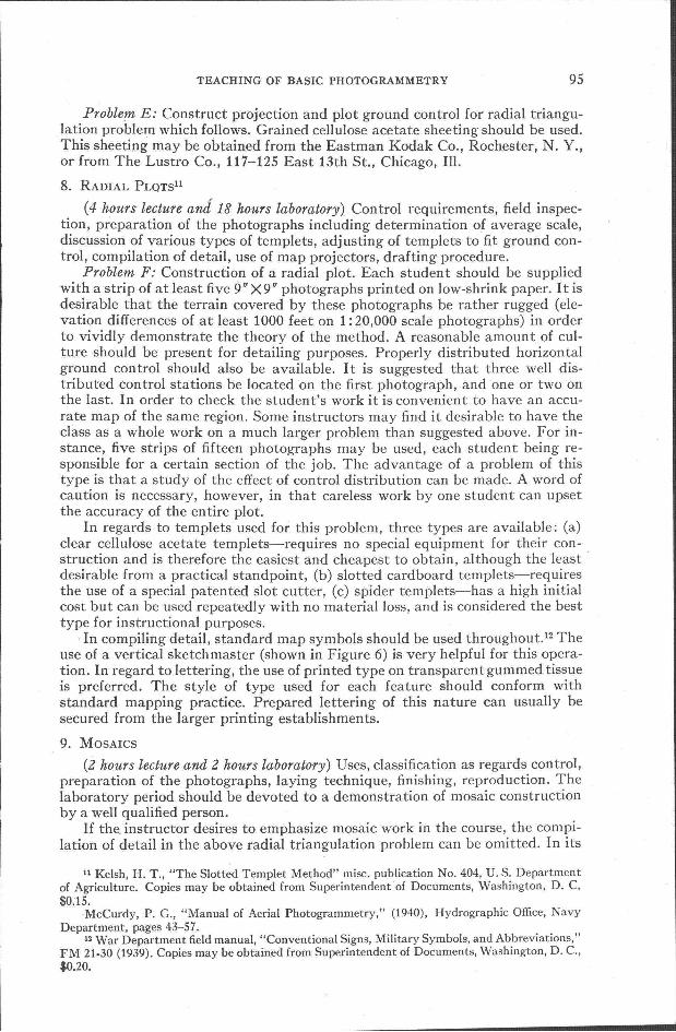
(4 hours lecture and 18 hours laboratory) Control requirements, field inspection, preparation of the photographs including determination of average scale,discussion of various types of templets, adjusting of templets to fit ground control, compilation of detail, use of map projectors, drafting procedure.
Problem F: Construction of a radial plot. Each student should be suppliedwith a strip of at least five 9" X9" photographs printed on low-shrink paper. It isdesirable that the terrain covered by these photographs be rather rugged (elevation differences of at least 1000 feet on 1: 20,000 scale photographs) in orderto vividly demonstrate the theory of the method. A reasonable amount of culture should be present for detailing purposes. Properly distributed horizontalground control should also be available. It is suggested that three well distributed control stations be located on the first photograph, and one or two onthe last. In order to check the student's work it is convenient to have an accurate map of the same region. Some instructors may find it desirable to have theclass as a whole work on a much larger problem than suggested above. For instance, five strips of fifteen photographs may be used, each student being responsible for a certain section of the job. The advantage of a problem of thistype is that a study of the effect of control distribution can be made. A word ofcaution is necessary, however, in that careless work by one student can upsetthe accuracy of the entire plot.
In regards to templets used for this problem, three types are available: (a)clear cellulose acetate templets-requires no special equipment for their construction and is therefore the easiest and cheapest to obtain, although the leastdesirable from a practical standpoint, (b) slotted cardboard templets-requiresthe use of a special patented slot cutter, (c) spider templets-has a high initialcost but can be used repeatedly with no material loss, and is considered the besttype for instructional purposes.
. In compiling detail, standard map symbols should be used throughout. 12 Theuse of a vertical sketch master (shown in Figure 6) is very helpful for this operation. In regard to lettering, the use of printed type on transparent gummed tissueis preferred. The style of type used for each feature should conform withstandard mapping practice. Prepared lettering of this nature can usually besecured from the larger printing establishments.
9. MOSAICS
(2 hours lecture and 2 hours laboratory) Uses, classification as regards control,preparation of the photographs, laying technique, finishing, reproduction. Thelaboratory period should be devoted to a demonstration of mosaic constructionby a well qualified person.
If the. instructor desires to emphasize mosaic work in the course, the compilation of detail in the above radial triangulation problem can be omitted. In its
11 Kelsh, H. T., "The Slotted Templet Method" misc. publication No. 404, U. S. Departmentof Agriculture. Copies may be obtained from Superintendent of Documents, Washington, D. C.$0.15.
McCurdy, P. G., "Manual of Aerial Photogrammetry," (1940), Hydrographic Office, NavyDepartment, pages 43-57.
12 War Department field manual, "Conventional Signs, Military Symbols, and Abbreviations,"FM 21-30 (1939). Copies may be obtained from Superintendent of Documents, Washington, D. C.,$0.20.
96 PHOTOGRAMMETRIC ENGINEERING
place can be substituted the construction of a controlled mosaic, using the radialplot as a base.
10. INTERPRETATION OF AERIAL PHOTOGRAPHS13
(2 hours lecture and 2 hours laboratory) Study of objects in regard to size,shape, shadows, tone, and texture. Identification of military installations, detection of camouflage, use of infra-red and color films, night photography withflash bombs. It is highly desirable that the students be furnished with photographs of nearby areas, so that actual field interpretation studies can be made.
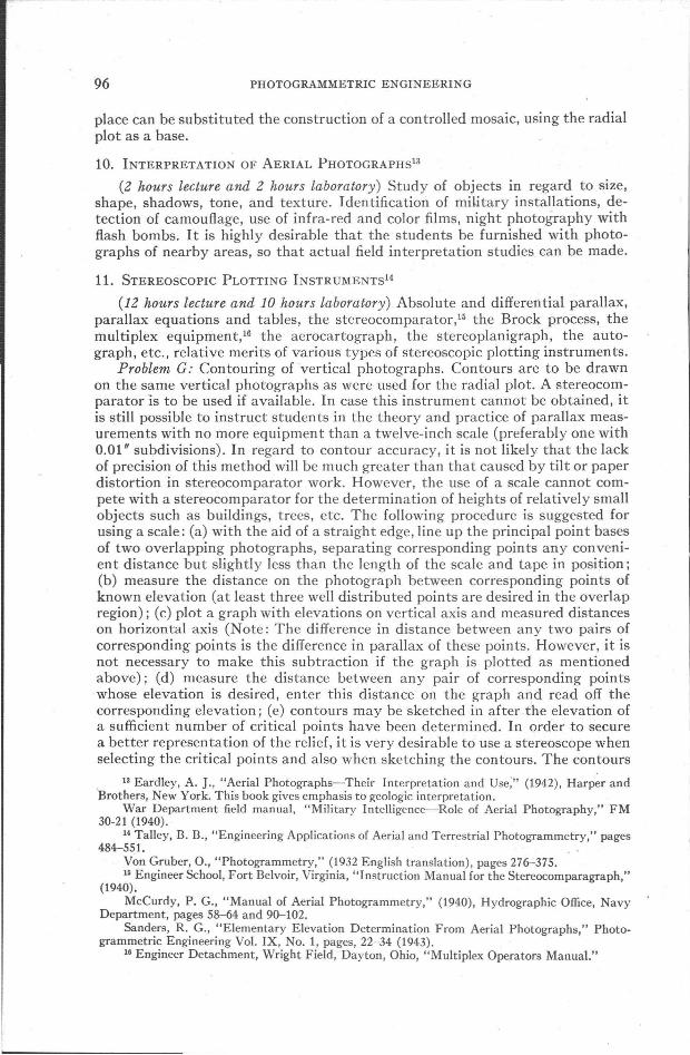
11. STEREOSCOPIC PLOTTING INSTRUMENTS14
(12 hours lecture and 10 hours laboratory) Absolute and differential parallax,parallax equations and tables, the stereocomparator,15 the Brock process, themultiplex equipment,16 the aerocartograph, the stereoplanigraph, the autograph, etc., relative merits of various types of stereoscopic plotting instruments.
Problem G: Contouring of vertical photographs. Contours are to be drawnon the same vertical photographs as were used for the radial plot. A stereocomparator IS to be used if available. In case this instrument cannot be obtained, itis still possible to instruct students in the theory and practice of parallax measurements with no more equipment than a twelve-inch scale (preferably one with0.01" subdivisions). In regard to contour accuracy, it is not likely that the lackof precision of this method will be much greater than that caused by tilt or paperdistortion in stereocomparator work. However, the use of a scale cannot compete with a stereocomparator for the determination of heights of relatively smallobjects such as buildings, trees, etc. The following procedure is suggested forusing a scale: (a) with the aid of a straight edge, line up the principal point basesof two overlapping photographs, separating corresponding points any convenient distance but slightly less than the length of the scale and tape in position;(b) measure the distance on the photograph between corresponding points ofknown elevation (at least three well distributed points are desired in the overlapregion); (c) plot a graph with elevations on vertical axis and measured distanceson horizontal axis (Note: The difference in distance between any two pairs ofcorresponding points is the difference in parallax of these points. However, it isnot necessary to make this subtraction if the graph is plotted as mentionedabove); (d) measure the distance between any pair of corresponding pointswhose elevation is desired, enter this distance on the graph and read off thecorresponding elevation; (e) contours may be sketched in after the elevation ofa sufficient number of critical points have been determined. In order to securea better representation of the relief, it is very desirable to use a stereoscope whenselecting the critical points and also when sketching the contours. The contours
13 Eardley, A. J., "Aerial Photographs-Their Interpretation and Use;" (1942), Harper and"Brothers, New York. This book gives emphasis to geologic interpretation.
War Department field manual, "Military Intelligence-Role of Aerial Photography," FM30-21 (1940).
14 Talley, B. B., "Engineering Applications of Aerial and Terrestrial Photogrammetry," pages484-551.
Von Gruber, 0., "Photogrammetry," (1932 English translation), pages 276-375.15 Engineer School, Fort Belvoir, Virginia, "Instruction Manual for the Stereocomparagraph,"
(1940).McCurdy, P. G., "Manual of Aerial Photogrammetry," (1940), Hydrographic Office, Navy
Department, pages 58-64 and 90-102.Sanders, R. G., "Elementary Elevation Determination From Aerial Photographs," Photo
grammetric Engineering Vol. IX, No.1, pages, 22-34 (1943).15 Engineer Detachment, Wright Field, Dayton, Ohio, "Multiplex Operators Manual."
TEACHING OF BASIC PHOTOGRAMMETRY
(a)
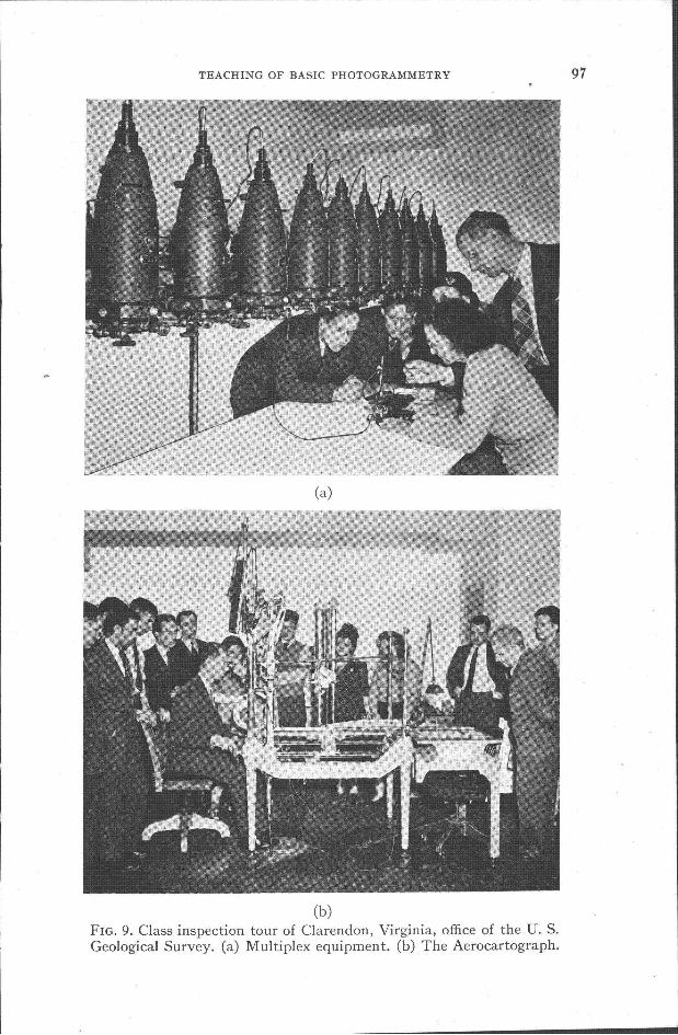
(b)FIG. 9. Class inspection tour of Clarendon, Virginia, office of the U. S.Geological Survey. (a) Multiplex equipment. (b) The Aerocartograph.
97
98 PHOTOGRAMMETRIC ENGINEERING
as sketched on the photographs represent a perspective view of the terrain.Their true plan position can be found as follows: (a) Locate by intersection, onthe previously run radial plot, the plan position of the critical points (spotheights) on the photographs, (b) adjust the contours to these points in the samemanner as was previously used in tracing off detail such as crooked roads orstreams.
12. MAPPING FROM OBLIQUE PHOTOGRAPHS17.
(4 hours lecture and 10 hours laboratory) Uses, geometrical relationships,graphical determination of horizontal and vertical angles, perspective grids. Instrumental methods including the Wilson photoalidade, the Miller single eyepiece' plotter, and others.
Problem H: Construction of perspective grid, using a high oblique photograph of flat terrain. Using this grid, transfer the detail from the photograph tothe plotting sheet.
Problem I: Graphical determination of horizontal and vertical angles fromoblique photographs. An instrument of recent development for obtaining horizontal angles from oblique photographs is the "Rectoblique Plotter" developedby J.G. Lewis of the U. S. Geological Survey. This plotter mechanically determines horizontal angles to various points on an oblique photograph and recordsthem graphically on a paper templet. It is hoped that a complete description ofthis instrument, as well as other phases of "tri-metrogon" mapping, will bepublished soon.
13. FURTHER ApPLICATIONS OF PHOTOGRAMMETRY
(4 hours lecture) GeQlogyI8 and mining, soil surveys, fprestry, route planning,water supply and sanitation, tax studies, city and regional planning, etc.
14. EXAMINATION AND DISCUSSION PERIODS
(12 hours) It is suggested that three 2-hour examinations be given during thecourse. Each examination should be followed by a 2-hour discussion period. Thewriter has found that the students benefit considerably from such discussions.
15. INSPECTION TOUR OF A MAPPING AGENCY
(2 hours) On tours such as these (see Figure 9) students see practical applications of the various principles discussed in class lectures.
IV. GENERAL TEXTBOOKS
Information concerning current books on photogrammetry is given below.Included in this list are several surveying books with one or more chapters onthe subject. Each student should be required to have a copy of the selected classtext. It is also desirable that one copy of each of the books listed be obtained forreference use.
n Wilson, R. M., "Oblique Photographs for the Surveyor," PHOTOGRAMMETRIC ENGINEERINGVol. VIII, No.1, pages 36-54 (1942).
Wilson, R. M., "Oblique Photographs and the Photoalidade," PHOTOGRAMMETRIC ENGINEERING, Vol. IV, No.2, pages 65-74 (1938).
Miller, O. M., "Topographical Mapping from High Oblique Air Photographs," PHOTOGRAMMETRIC ENGINEERING Vol. VIII, No.1, pages 55-79 (1942).
Department of the Interior (Canada), "The Use of Aerial Photographs for Mapping," Topographical Survey Bulletin No. 62, pages 12-31 (1932).
18 Smith, H. T. U., "Aerial Photographs in Geomorphic Studies," Photogrammetric Engineering Vol. VIII, No.2, pages 129-155 (1942).
TEACHING OF BASIC PHOTOGRAMMETRY 99
American Society of Photogrammetry, "Manual of Aerial Photogrammetry."This is being published by the society with the co-operation of specialists in thevarious branches of the profession. A proposed list of contents is given in PHOTOGRAMMETRIC ENGINEERING, Vol. VII, No.4. Up to the present time seven chapters have been completed, including one devoted to the definition of terms usedin photogrammetry (see Vol. VIII, No.4). After the chapters have been published individually, it is the intention of the society to publish the complete setin book form, making the necessary revisions to properly co-ordinate the varioussubjects. .
Bagley, James W., "Aerophotography and Aerosurveying," (1941), 324pages, $3.50, McGraw-Hill Book Co., Inc., New York. It is the opinion of thewriter that this is the best textbook on general photogrammetry published inthe United States up to the present time. However, the following changes wouldprobably increase its usefulness: Revision of terminology to agree with generalusage; revision of chapter on photographic transformation, emphasizing thepractical rectification of nominally vertical single lens photographs; inclusion ofmore information on stereoscopic plotting instruments; inclusion of problemsat the end of each chapter.
Breed and Hosmer, "Higher Surveying," (1940), $3.50, John Wiley and Sons,Inc., New York. The section of the book devoted to photogrammetry (152pages) is intended to form a part of a typical surveying course and does not contain enough material for a course entirely devoted to photogrammetry, unlesssupplemented by considerable outside material. Considering the limited spaceavailable, too much emphasis is placed on terrestrial photogrammetry.
Davis and Foote, "Surveying," (1940), $5.00, McGraw-Hill Book Co., Inc.,New York. Contains a chapter of 63 pages on "Photogrammetric Surveying"written by B. B. Talley. The chapter gives a brief but excellent discussion ofpractically all branches of the subject, and therefore should prove useful as anintroduction to photogrammetry in a regular surveying course.
Hart, C. A., "Air Photography Applied to Surveying," (1940), 366 pages,$7.50, Longmans, Green and Co., New York. This book, written by an Englishauthor, gives a well balanced presentation of the entire field of photogrammetrywith special emphasis on methods and equipment used in the British Empire.The book should prove valuable as a class reference.
Hotine, M., "Surveying from Air Photographs," (1931),250 pages, printedin Great Britain but copies can be secured through G. E. Stechert and Co., NewYork. This book contains excellent basic information on all phases of photogrammetry except photography, optics, and types of aerial cameras. Due tothe many new developments made in this field in the past twelve years someparts of the book are now obsolete.
McCurdy, P. G., "Manual of Aerial Photogrammetry," (1940), 102 pages,printed by Hydrographic Office, Navy Department. Describes the graphicalmethods used by this organization for mapping from vertical and oblique photographs. Of special interest is the manner in which the construction of a radialplot is presented, excellent diagrams and halftone reproductions of sample photographs being included to illustrate each step.
Raynor, W. H., "Advanced Surveying," (1941), $3.25, D. Van Nostrand Co.,Inc., New York. Contains a chapter of 60 pages devoted to a general discussionof photogrammetry. Should prove useful as an introduction to the subject in aregular surveying course.
Sharp, H. 0., "Photogrammetry," (1943), 129 pages (8t X 11), $3.50, JohnWiley and Sons, Inc., New York. This book was prepared by Prof. Sharp for use
100 PHOTOGRAMMETRIC ENGINEERING
as a text at Rensselaer Polytechnic Institute. It is believed that an improvementcould be made in this book by rearranging the subjects in a more logical manner. Also information on mosaics, photographic materials, and photographiclaboratory technique might be included.
Talley, B. B., "Engineering Applications of Aerial and Terrestrial Photogrammetry," (1938), 612 pages, $10.00, Pitman Publishing Corp., New York.This was the first complete book on photogrammetry published in the UnitedStates. It is hoped that a revision will be made sometime in the near future soas to include recent developments. The book is useful as a class reference, especially in the fields of aerial cameras and stereoscopic plotting instruments.
Von Gruber, 0., "Photogrammetry," (1932 English Translation), 454 pages,$8,00, American Photographic Publishing Co., 428 Newbury St., Boston, Mass.The greater part of the book is devoted to a thorough discussion of the theoryand operation of stereoscopic plotting instruments, and therefore serves as anexcellent reference book in this field. Chapters are also included on the geometryof the photograph, aerial camera lenses, and shutters. Practically no informationis given on graphical methods of compilation.
Whitmore, G. D., "Elements of Photogrammetry," (1941), 136 pages, $1.75,International Textbook Co., Scranton, Pa. An excellent book on elementaryphotogrammetry. It is written in such a style that beginners will find no difficultyin understanding the principles presented.
War Department-The following technical and field manuals have been prepared by this organization for use as training texts for army personnel. Thesemanuals may be obtained from the Superintendent of Documents, WashingtonD. c., at the indicated prices.
"Advanced Map and Aerial Photograph Reading," FM 21-26 (1941), 190pages, $0.20. Entirely devoted to reading of maps and photographs. It is a desirable text for beginners.
"Basic Photography," TM 1-219 (1941),342 pages, $0.50. Contains desirable material for those interested in photographic laboratory procedure.
"Topographic Drafting," TM 5-230 (1940), 302 pages, $1.00. In addition todiscussing topographic drafting, more than one-half of the text is devoted tomap preparation from aerial photographs, with emphasis on drafting procedure.Considerable space is given to the operation of the stereocomparagraph, including parallax tables. If this book is supplemented by other material it would beuseful as a text in elementary photogrammetry.
"Aerial Phototopography," TM 5-240 (1941), 104 pages, $0.15. Chiefly devoted to mapping procedure by the multiplex method, and to the preparation ofradial plots from tandem T-3A photographs.