teaching adolescent english language learners - caslon publishing
TRANSCRIPT

Real-TimeUser ManualLabVIEW Real-Time User Manual
April 2001 EditionPart Number 322154C-01
Support
Worldwide Technical Support and Product Information
ni.com
National Instruments Corporate Headquarters
11500 North Mopac Expressway Austin, Texas 78759-3504 USA Tel: 512 794 0100
Worldwide Offices
Australia 03 9879 5166, Austria 0662 45 79 90 0, Belgium 02 757 00 20, Brazil 011 284 5011,Canada (Calgary) 403 274 9391, Canada (Ottawa) 613 233 5949, Canada (Québec) 514 694 8521,China (Shanghai) 021 6555 7838, China (ShenZhen) 0755 3904939, Denmark 45 76 26 00,Finland 09 725 725 11, France 01 48 14 24 24, Germany 089 741 31 30, Greece 30 1 42 96 427,Hong Kong 2645 3186, India 91805275406, Israel 03 6120092, Italy 02 413091, Japan 03 5472 2970,Korea 02 596 7456, Mexico 5 280 7625, Netherlands 0348 433466, New Zealand 09 914 0488,Norway 32 27 73 00, Poland 0 22 528 94 06, Portugal 351 1 726 9011, Singapore 2265886, Spain 91 640 0085,Sweden 08 587 895 00, Switzerland 056 200 51 51, Taiwan 02 2528 7227, United Kingdom 01635 523545
For further support information, see the Technical Support Resources appendix. To comment on thedocumentation, send e-mail to [email protected]
© Copyright 1999, 2001 National Instruments Corporation. All rights reserved.
Important Information
WarrantyThe media on which you receive National Instruments software are warranted not to fail to execute programming instructions,due to defects in materials and workmanship, for a period of 90 days from date of shipment, as evidenced by receipts or otherdocumentation. National Instruments will, at its option, repair or replace software media that do not execute programminginstructions if National Instruments receives notice of such defects during the warranty period. National Instruments does notwarrant that the operation of the software shall be uninterrupted or error free.
A Return Material Authorization (RMA) number must be obtained from the factory and clearly marked on the outside ofthe package before any equipment will be accepted for warranty work. National Instruments will pay the shipping costs ofreturning to the owner parts which are covered by warranty.
National Instruments believes that the information in this document is accurate. The document has been carefully reviewedfor technical accuracy. In the event that technical or typographical errors exist, National Instruments reserves the right tomake changes to subsequent editions of this document without prior notice to holders of this edition. The reader should consultNational Instruments if errors are suspected. In no event shall National Instruments be liable for any damages arising out ofor related to this document or the information contained in it.
EXCEPT AS SPECIFIED HEREIN, NATIONAL INSTRUMENTS MAKES NO WARRANTIES, EXPRESS OR IMPLIED, AND SPECIFICALLY DISCLAIMS ANY
WARRANTY OF MERCHANTABILITY OR FITNESS FOR A PARTICULAR PURPOSE. CUSTOMER’S RIGHT TO RECOVER DAMAGES CAUSED BY FAULT OR
NEGLIGENCE ON THE PART OF NATIONAL INSTRUMENTS SHALL BE LIMITED TO THE AMOUNT THERETOFORE PAID BY THE CUSTOMER. NATIONAL
INSTRUMENTS WILL NOT BE LIABLE FOR DAMAGES RESULTING FROM LOSS OF DATA, PROFITS, USE OF PRODUCTS, OR INCIDENTAL OR
CONSEQUENTIAL DAMAGES, EVEN IF ADVISED OF THE POSSIBILITY THEREOF. This limitation of the liability of National Instruments willapply regardless of the form of action, whether in contract or tort, including negligence. Any action against National Instrumentsmust be brought within one year after the cause of action accrues. National Instruments shall not be liable for any delay inperformance due to causes beyond its reasonable control. The warranty provided herein does not cover damages, defects,malfunctions, or service failures caused by owner’s failure to follow the National Instruments installation, operation, ormaintenance instructions; owner’s modification of the product; owner’s abuse, misuse, or negligent acts; and power failure orsurges, fire, flood, accident, actions of third parties, or other events outside reasonable control.
CopyrightUnder the copyright laws, this publication may not be reproduced or transmitted in any form, electronic or mechanical, includingphotocopying, recording, storing in an information retrieval system, or translating, in whole or in part, without the prior writtenconsent of National Instruments Corporation.
TrademarksLabVIEW™, National Instruments™, ni.com™, NI-DAQ™, and PXI™ are trademarks of National Instruments Corporation.
Product and company names mentioned herein are trademarks or trade names of their respective companies.
WARNING REGARDING USE OF NATIONAL INSTRUMENTS PRODUCTS(1) NATIONAL INSTRUMENTS PRODUCTS ARE NOT DESIGNED WITH COMPONENTS AND TESTING FOR A LEVELOF RELIABILITY SUITABLE FOR USE IN OR IN CONNECTION WITH SURGICAL IMPLANTS OR AS CRITICALCOMPONENTS IN ANY LIFE SUPPORT SYSTEMS WHOSE FAILURE TO PERFORM CAN REASONABLY BEEXPECTED TO CAUSE SIGNIFICANT INJURY TO A HUMAN.
(2) IN ANY APPLICATION, INCLUDING THE ABOVE, RELIABILITY OF OPERATION OF THE SOFTWARE PRODUCTSCAN BE IMPAIRED BY ADVERSE FACTORS, INCLUDING BUT NOT LIMITED TO FLUCTUATIONS IN ELECTRICALPOWER SUPPLY, COMPUTER HARDWARE MALFUNCTIONS, COMPUTER OPERATING SYSTEM SOFTWAREFITNESS, FITNESS OF COMPILERS AND DEVELOPMENT SOFTWARE USED TO DEVELOP AN APPLICATION,INSTALLATION ERRORS, SOFTWARE AND HARDWARE COMPATIBILITY PROBLEMS, MALFUNCTIONS ORFAILURES OF ELECTRONIC MONITORING OR CONTROL DEVICES, TRANSIENT FAILURES OF ELECTRONICSYSTEMS (HARDWARE AND/OR SOFTWARE), UNANTICIPATED USES OR MISUSES, OR ERRORS ON THE PART OFTHE USER OR APPLICATIONS DESIGNER (ADVERSE FACTORS SUCH AS THESE ARE HEREAFTERCOLLECTIVELY TERMED “SYSTEM FAILURES”). ANY APPLICATION WHERE A SYSTEM FAILURE WOULDCREATE A RISK OF HARM TO PROPERTY OR PERSONS (INCLUDING THE RISK OF BODILY INJURY AND DEATH)SHOULD NOT BE RELIANT SOLELY UPON ONE FORM OF ELECTRONIC SYSTEM DUE TO THE RISK OF SYSTEMFAILURE. TO AVOID DAMAGE, INJURY, OR DEATH, THE USER OR APPLICATION DESIGNER MUST TAKEREASONABLY PRUDENT STEPS TO PROTECT AGAINST SYSTEM FAILURES, INCLUDING BUT NOT LIMITED TOBACK-UP OR SHUT DOWN MECHANISMS. BECAUSE EACH END-USER SYSTEM IS CUSTOMIZED AND DIFFERSFROM NATIONAL INSTRUMENTS' TESTING PLATFORMS AND BECAUSE A USER OR APPLICATION DESIGNERMAY USE NATIONAL INSTRUMENTS PRODUCTS IN COMBINATION WITH OTHER PRODUCTS IN A MANNER NOTEVALUATED OR CONTEMPLATED BY NATIONAL INSTRUMENTS, THE USER OR APPLICATION DESIGNER ISULTIMATELY RESPONSIBLE FOR VERIFYING AND VALIDATING THE SUITABILITY OF NATIONALINSTRUMENTS PRODUCTS WHENEVER NATIONAL INSTRUMENTS PRODUCTS ARE INCORPORATED IN ASYSTEM OR APPLICATION, INCLUDING, WITHOUT LIMITATION, THE APPROPRIATE DESIGN, PROCESS ANDSAFETY LEVEL OF SUCH SYSTEM OR APPLICATION.


© National Instruments Corporation v LabVIEW RT User Manual
Contents
About This ManualConventions ...................................................................................................................viiRelated Documentation..................................................................................................viii
Chapter 1Introduction
Plug-In RT Series DAQ Devices ...................................................................................1-2Networked RT Series Devices .......................................................................................1-2Architecture of LabVIEW RT .......................................................................................1-2
RT Development System.................................................................................1-4RT Engine........................................................................................................1-5
System and Local Time on the RT Engine .......................................1-5
Chapter 2Installation
Installing the Software ...................................................................................................2-1
Chapter 3Software Overview
Operating LabVIEW RT................................................................................................3-1Launching LabVIEW RT ................................................................................3-1Downloading VIs.............................................................................................3-2Debugging LabVIEW RT VIs.........................................................................3-3Creating Stand-Alone Applications.................................................................3-3
Programming LabVIEW RT..........................................................................................3-5Using the RT Development System ................................................................3-6
Acquiring RT Engine Information....................................................3-6Switching LabVIEW RT Execution Targets ....................................3-7Connecting to the RT Engine with VIs Already Running ................3-7Exiting the RT Development System................................................3-8
Communicating Using Host LabVIEW Applications .....................................3-9TCP/IP...............................................................................................3-9Distributed Computing with the VI Server .......................................3-10Shared Memory (RT Series DAQ Devices Only).............................3-10
Contents
LabVIEW RT User Manual vi ni.com
Chapter 4Real-Time Programming
Real-Time Performance of VIs ..................................................................................... 4-1Time-Critical Priority...................................................................................... 4-1Real-Time Features of the LabVIEW RT Environment ................................. 4-2Running a VI at Time-Critical Priority in the RT Development System........ 4-2Running a VI at Time-Critical Priority without
the RT Development System ....................................................................... 4-3Performance of LabVIEW RT VIs................................................................................ 4-3
Writing Efficient Loops .................................................................................. 4-4Improving DAQ Configuration ........................................................ 4-4Removing Redundant Operations..................................................... 4-4Setting the Priorities of SubVIs ........................................................ 4-4Avoiding Array Copying .................................................................. 4-5
Appendix ATechnical Support Resources
Glossary
Index

© National Instruments Corporation vii LabVIEW Real-Time User Manual
About This Manual
This manual contains introductory and installation information aboutLabVIEW Real-Time (RT) software and describes how to use theLabVIEW RT software.
ConventionsThe following conventions appear in this manual:
» The » symbol leads you through nested menu items and dialog box optionsto a final action. The sequence File»Page Setup»Options directs you topull down the File menu, select the Page Setup item, and select Optionsfrom the last dialog box.
This icon denotes a tip, which alerts you to advisory information.
This icon denotes a note, which alerts you to important information.
bold Bold text denotes items that you must select or click on in the software,such as menu items and dialog box options. Bold text also denotesparameter names.
italic Italic text denotes variables, emphasis, a cross reference, or an introductionto a key concept. This font also denotes text that is a placeholder for a wordor value that you must supply.
monospace Text in this font denotes text or characters that you should enter from thekeyboard, sections of code, programming examples, and syntax examples.This font is also used for the proper names of disk drives, paths, directories,programs, subprograms, subroutines, device names, functions, operations,variables, filenames and extensions, and code excerpts.
monospace italic Italic text in this font denotes text that is a placeholder for a word or valuethat you must supply.

About This Manual
LabVIEW Real-Time User Manual viii ni.com
Related DocumentationThe following documents contain information that you might find helpfulas you read this manual:
• your target-specific RT Series hardware user manual
• LabVIEW Real-Time Release Notes
• LabVIEW Real-Time Help, available by selectingHelp»LabVIEW Real-Time Help
• Getting Started with LabVIEW
• LabVIEW User Manual
• LabVIEW Measurements Manual
• LabVIEW Help, available by selecting Help»Contents and Index
• LabVIEW Application Builder Release Notes

© National Instruments Corporation 1-1 LabVIEW Real-Time User Manual
1Introduction
Most LabVIEW applications run on general-purpose operatingsystems like Microsoft Windows. Some LabVIEW applicationsrequire deterministic real-time performance that non-real-time operatingsystems like Windows cannot guarantee. LabVIEW Real-Time (RT)addresses the need for deterministic real-time performance usingLabVIEW.
LabVIEW RT combines the ease of use of LabVIEW with the power ofreal-time systems so you can create deterministic applications usinggraphical programming. Real-time applications run on RT Series hardware,either plug-in data acquisition devices or networked RT Series devices.Embedded LabVIEW RT applications do not have a user interface, so theymust have a host PC to generate the user interface. You create embedded,real-time LabVIEW RT applications from a host development system. TheLabVIEW RT Development System runs on Windows, just like LabVIEW.You can develop code in the LabVIEW RT Development System anddownload real-time code to run embedded applications on a hardwaretarget.
General-purpose operating systems can crash or hang, which causesprograms to quit running. Because embedded LabVIEW RT applicationsrun on a separate hardware platform, they do not stop executing if thehost PC operating system crashes. If a crash occurs on the host PCoperating system, the user interface is lost, and any other communicationbetween an embedded LabVIEW RT application and the host PC ceases.Embedded LabVIEW RT applications continue to run, even after the hostPC operating system crashes.
You can reboot the host PC without disrupting embedded LabVIEW RTapplications. After you reboot the host PC, you can reestablishcommunication between the host PC and the embedded LabVIEW RTapplication. You also can design your applications to retrieve any data thatwas collected on RT Series hardware while the host PC was not incommunication with the embedded LabVIEW RT application.
Chapter 1 Introduction
LabVIEW Real-Time User Manual 1-2 ni.com
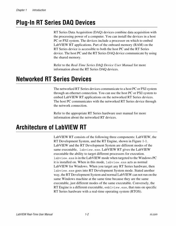
Plug-In RT Series DAQ DevicesRT Series Data Acquisition (DAQ) devices combine data acquisition withthe processing power of a computer. You can install the devices in a hostPC or PXI system. The devices include a processor on which to embedLabVIEW RT applications. Part of the onboard memory (RAM) on theRT Series device is accessible to both the host PC and the RT Seriesdevice. The host PC and the RT Series DAQ device communicate by usingthe shared memory.
Refer to the Real-Time Series DAQ Device User Manual for moreinformation about the RT Series DAQ devices.
Networked RT Series DevicesThe networked RT Series devices communicate to a host PC or PXI systemthrough an ethernet connection. You can use the host PC or PXI system toembed LabVIEW RT applications on the networked RT Series devices.The host PC communicates with the networked RT Series device throughthe network connection.
Refer to the appropriate RT Series hardware user manual for moreinformation about the networked RT devices.
Architecture of LabVIEW RTLabVIEW RT consists of the following three components: LabVIEW, theRT Development System, and the RT Engine, shown in Figure 1-1.LabVIEW and the RT Development System are different modes of thesame executable, labview.exe. LabVIEW RT gives the LabVIEWexecutable the ability to target different processors for execution.labview.exe is in the LabVIEW mode when targeted to the Windows PCit is installed on. When in this mode, labview.exe acts as normalLabVIEW for Windows. When you target any RT Series hardware, thenlabview.exe goes into RT Development System mode. Stated anotherway, the RT Development System and normal LabVIEW can not run on thesame Windows machine at the same time because they are the sameexecutable, just different modes of the same executable. Conversely, theRT Engine is a different executable, emblview.exe, that runs on specificRT Series hardware with a real-time operating system (RTOS).
Chapter 1 Introduction
© National Instruments Corporation 1-3 LabVIEW Real-Time User Manual
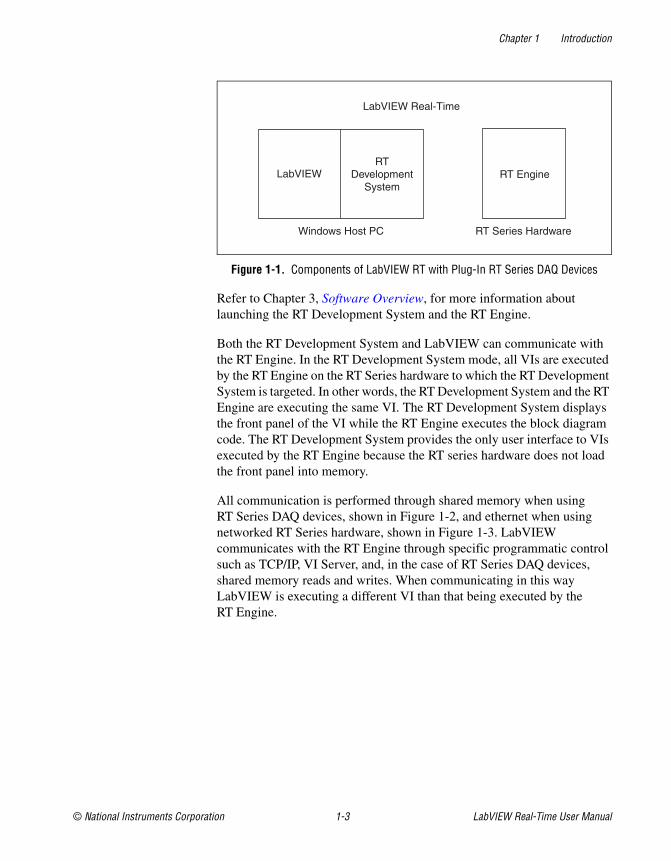
Figure 1-1. Components of LabVIEW RT with Plug-In RT Series DAQ Devices
Refer to Chapter 3, Software Overview, for more information aboutlaunching the RT Development System and the RT Engine.
Both the RT Development System and LabVIEW can communicate withthe RT Engine. In the RT Development System mode, all VIs are executedby the RT Engine on the RT Series hardware to which the RT DevelopmentSystem is targeted. In other words, the RT Development System and the RTEngine are executing the same VI. The RT Development System displaysthe front panel of the VI while the RT Engine executes the block diagramcode. The RT Development System provides the only user interface to VIsexecuted by the RT Engine because the RT series hardware does not loadthe front panel into memory.
All communication is performed through shared memory when usingRT Series DAQ devices, shown in Figure 1-2, and ethernet when usingnetworked RT Series hardware, shown in Figure 1-3. LabVIEWcommunicates with the RT Engine through specific programmatic controlsuch as TCP/IP, VI Server, and, in the case of RT Series DAQ devices,shared memory reads and writes. When communicating in this wayLabVIEW is executing a different VI than that being executed by theRT Engine.
LabVIEW Real-Time
LabVIEWRT
DevelopmentSystem
Windows Host PC RT Series Hardware
RT Engine
Chapter 1 Introduction
LabVIEW Real-Time User Manual 1-4 ni.com
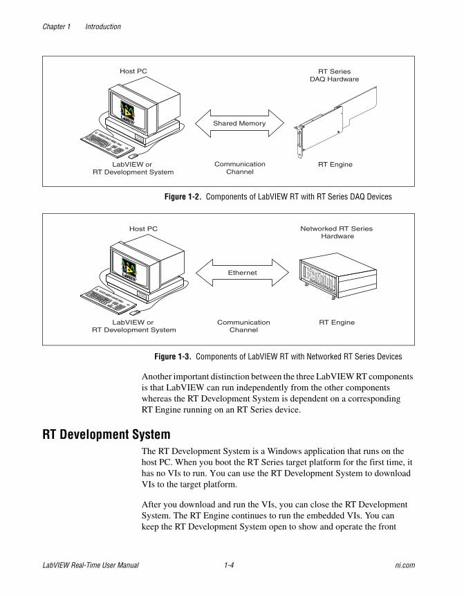
Figure 1-2. Components of LabVIEW RT with RT Series DAQ Devices
Figure 1-3. Components of LabVIEW RT with Networked RT Series Devices
Another important distinction between the three LabVIEW RT componentsis that LabVIEW can run independently from the other componentswhereas the RT Development System is dependent on a correspondingRT Engine running on an RT Series device.
RT Development SystemThe RT Development System is a Windows application that runs on thehost PC. When you boot the RT Series target platform for the first time, ithas no VIs to run. You can use the RT Development System to downloadVIs to the target platform.
After you download and run the VIs, you can close the RT DevelopmentSystem. The RT Engine continues to run the embedded VIs. You cankeep the RT Development System open to show and operate the front
CommunicationChannel
RT SeriesDAQ Hardware
RT EngineLabVIEW orRT Development System
Host PC
Shared Memory
CommunicationChannel
RT EngineLabVIEW orRT Development System
Host PC Networked RT SeriesHardware
Ethernet

Chapter 1 Introduction
© National Instruments Corporation 1-5 LabVIEW Real-Time User Manual
panel of the embedded VI. When VIs run on the target platform, theRT Development System exchanges messages with the RT Engine toupdate the controls and indicators on the front panel. Thesecommunications are built into the RT Development System andembedded software, so they occur automatically.
Note When you open the front panel of an embedded LabVIEW RT VI in theRT Development System, real-time performance of the VI cannot be ensured. Refer toChapter 4, Real-Time Programming, for more information about real-time programming.
You can use the RT Development System to debug embedded LabVIEWRT VIs while the embedded LabVIEW RT VIs run on the target platform.You can use LabVIEW debugging tools, such as probes, breakpoints, andsingle stepping.
RT EngineThe RT Engine on the target platform runs the LabVIEW RT VIs youdownloaded to the target platform using the RT Development System.The RT Engine can provide deterministic real-time performance for thefollowing reasons:
• The RT Engine runs on a real-time operating system, which ensuresthat the scheduler and other operating system services adhere toreal-time operation.
• The RT Engine does not run on the host PC but on the RT Serieshardware. Unnecessary applications or device drivers, such asvideo drivers, do not run on the RT Series hardware. The absence ofextraneous software and drivers means that a third-party applicationor driver does not impede LabVIEW RT applications.
• The RT Engine is tuned for real-time performance.
• The RT Series hardware uses no virtual memory. By not using virtualmemory a major source of unpredictability in deterministic systems iseliminated.
System and Local Time on the RT EngineWhen running on Windows, certain LabVIEW date/time functions adjusttime values based on the time zone information from the operating system.Some examples of time zone adjustments from the operating system can beseen when using the Seconds to Date/Time function or when a chart axismarker has been formatted to show date and time. Due to limitations of thereal-time operating system on RT Series devices, the RT Engine does notsupport time zone information. As a result, system time and local time are

Chapter 1 Introduction
LabVIEW Real-Time User Manual 1-6 ni.com
treated the same in the RT Engine. Functions such as Seconds toDate/Time do not adjust time values based on the local time zone.Therefore, date/time functions produce different results in the RT Enginethan when used in LabVIEW on the host PC.

© National Instruments Corporation 2-1 LabVIEW RT User Manual
2Installation
This chapter explains how to install LabVIEW Real-Time (RT).
Installing the SoftwareComplete the following steps to install LabVIEW RT on the host PC orPXI system.
1. If you are not installing LabVIEW RT on Windows NT, proceed tostep 2. If you are installing LabVIEW RT on Windows NT, log onto Windows NT as an administrator or as a user with administratorprivileges.
2. Insert the LabVIEW RT CD into your CD drive. The LabVIEW RTinstallation program runs automatically.
3. Click Install LabVIEW RT. Follow the instructions that appear onyour screen.
When installing LabVIEW RT for use with a networked RT Series device,you must complete the additional steps to configure and install software onthe networked RT Series device. Refer to the networked RT Series deviceuser manual for more information on configuring your device.

© National Instruments Corporation 3-1 LabVIEW Real-Time User Manual
3Software Overview
This chapter describes how to operate and program in LabVIEWReal-Time (RT).
Operating LabVIEW RTThis section describes the basic operating procedures forLabVIEW Real-Time (RT), such as launching LabVIEW RT,downloading VIs, debugging LabVIEW RT VIs, and creating stand-aloneapplications.
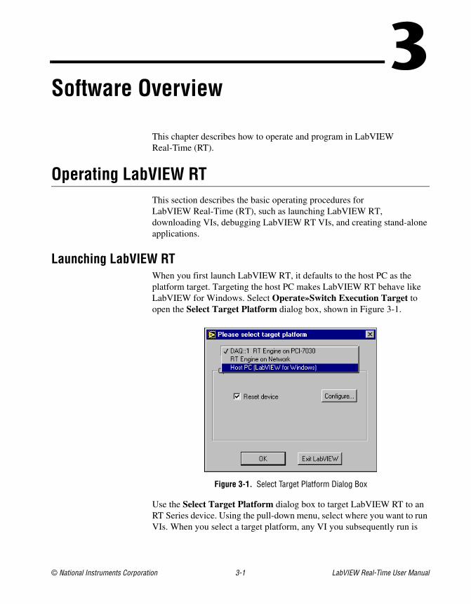
Launching LabVIEW RTWhen you first launch LabVIEW RT, it defaults to the host PC as theplatform target. Targeting the host PC makes LabVIEW RT behave likeLabVIEW for Windows. Select Operate»Switch Execution Target toopen the Select Target Platform dialog box, shown in Figure 3-1.
Figure 3-1. Select Target Platform Dialog Box
Use the Select Target Platform dialog box to target LabVIEW RT to anRT Series device. Using the pull-down menu, select where you want to runVIs. When you select a target platform, any VI you subsequently run is
Chapter 3 Software Overview
LabVIEW Real-Time User Manual 3-2 ni.com
downloaded to that target platform, where it can be executed. Click OK tolaunch the RT Development System.
The list of possible targets changes based on the number of RT Series DAQdevices configured on your system. If you do not configure any RT SeriesDAQ devices, only the RT Engine on Network and Host PC optionsappear in the Select Target Platform dialog box.
When you select an RT Engine target, various options specific to that targetappear. Refer to the corresponding RT Series hardware user manual formore information about the options for a specific RT Engine target.
Complete the following steps to change your preferences so the SelectTarget Platform dialog box appears when you launch LabVIEW RT.
1. Select Tools»Options. The Options dialog box appears.
2. Select Miscellaneous from the pull-down menu.
3. Click the Prompt for Target Execution Engine checkbox.
4. Click OK.
With the exception of the Prompt for Target Execution Engine option,all LabVIEW RT options are the same as normal LabVIEW for Windowsoptions.
Downloading VIsWhen you select an RT Engine target in the Select Target Platform dialogbox, the RT Development System establishes a connection with thatRT Engine target platform. When you open VIs and click the Run button,the RT Development System downloads the VI and its associated subVIsto the target platform. The RT Engine on the target platform then runsthe VI.
Note When you make changes to a VI, such as when you edit the VI or when you convertthe VI from a different version of LabVIEW, you must save the VI on the host PC beforeyou can download and run it on the RT Engine.
You can download LabVIEW RT VIs without running them by selectingOperate»Download Application. Download LabVIEW RT VIs withoutrunning them if you want to use the LabVIEW VI Server toprogrammatically run these VIs later.
Chapter 3 Software Overview
© National Instruments Corporation 3-3 LabVIEW Real-Time User Manual
To see which VIs have been downloaded to your target platform, selectBrowse»Show VI Hierarchy from the RT Development System. The VIhierarchy appears with a thumb tack in the upper left corner of each VI.
When the thumb tack is in the vertical position, as shown on the left, the VIhas been downloaded.
When the thumb tack is in the horizontal position, as shown on the left,you need to download the VI to run it.
Because the VI Server does not download VIs, you must manuallydownload VIs you need to call for use with the VI Server. Refer to theDistributed Computing with the VI Server section of this chapter, andChapter 16, Programmatically Controlling VIs, of the LabVIEWUser Manual, for more information about the VI Server.
Debugging LabVIEW RT VIsYou debug LabVIEW RT VIs in the RT Development System the sameway you debug any VI. All the existing LabVIEW debugging tools, exceptthe Call List Window, are available in the RT Development System. Referto Chapter 4, Debugging, of the Getting Started with LabVIEW manual,and the Debugging Techniques section in Chapter 6, Running andDebugging VIs, of the LabVIEW User Manual, for more information aboutthe LabVIEW debugging features.
Creating Stand-Alone ApplicationsApplications you build using the LabVIEW RT Professional DevelopmentSystem or the Application Builder can target VIs to RT Series devices orthe host PC. Use the LabVIEW RT Application Builder in the same manneras the LabVIEW Application Builder, with the exception of the ShowLabVIEW RT Target selection when Launched and the QuitLabVIEW RT host application after downloading options explainedlater in this section. Refer to your LabVIEW Application Builder ReleaseNotes for more information about the LabVIEW Application Builder.
The use of the Application Builder varies depending on the platform towhich you target LabVIEW RT. The information in this manual applies tousing the Application Builder when targeted to the host PC. Refer to yourRT Series hardware user manual for more information about using theApplication Builder when targeted to the RT Series hardware.
Chapter 3 Software Overview
LabVIEW Real-Time User Manual 3-4 ni.com
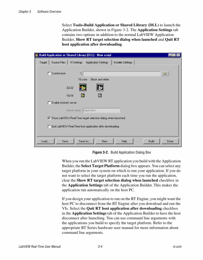
Select Tools»Build Application or Shared Library (DLL) to launch theApplication Builder, shown in Figure 3-2. The Application Settings tabcontains two options in addition to the normal LabVIEW ApplicationBuilder, Show RT target selection dialog when launched and Quit RThost application after downloading.
Figure 3-2. Build Application Dialog Box
When you run the LabVIEW RT application you build with the ApplicationBuilder, the Select Target Platform dialog box appears. You can select anytarget platform in your system on which to run your application. If you donot want to select the target platform each time you run the application,clear the Show RT target selection dialog when launched checkbox inthe Application Settings tab of the Application Builder. This makes theapplication run automatically on the host PC.
If you design your application to run on the RT Engine, you might want thehost PC to disconnect from the RT Engine after you download and run theVIs. Select the Quit RT host application after downloading checkboxin the Application Settings tab of the Application Builder to have the hostdisconnect after launching. You can use command line arguments withthe applications you build to specify the target platform. Refer to theappropriate RT Series hardware user manual for more information aboutcommand line arguments.

Chapter 3 Software Overview
© National Instruments Corporation 3-5 LabVIEW Real-Time User Manual
Selecting the Quit RT host application after downloading option in theApplication Builder is equivalent to selecting File»Exit without closingRT Engine VIs in the RT Development System. Refer to the Exiting the RTDevelopment System section later in this chapter for more informationabout exiting the RT system.
In addition to building applications, the Application Builder can createan installer for your application. Select the Installer tab in the BuildApplication or Shared Library (DLL) dialog box to access installeroptions. In the Advanced Installer Settings, select Install LabVIEWRun-Time Engine to add the LabVIEW RT Run-Time Engine installer.The LabVIEW RT Run-Time Engine installer includes support for RTSeries devices. You can use the LabVIEW RT Run-Time Engine to targetthe application to RT Series hardware from the machine on which theapplication is installed.
Some RT Series devices have media storage capability, such as the harddrive on a PXI controller. For these devices you can embed applications youbuild directly onto the RT Series device. Refer to your RT Series hardwareuser manual for additional information on embedded applications.
Programming LabVIEW RTA LabVIEW RT application runs on the RT Series hardware target andcontrols or monitors external events through the target hardware I/O, suchas analog and digital I/O channels of a DAQ device.
Because the RT Engine runs on hardware platforms that do not have all thecomponents of a PC, the RT applications you build lack some LabVIEWfeatures when you target the application to the RT Engine. For example, theRT Series DAQ device does not have a disk drive, so it does not support fileI/O. Refer to your RT Series hardware user manual for more informationabout support of specific LabVIEW functions.
If you attempt to download and run a VI on your target platform that hasany of the unsupported functionality, the VI still executes. Unsupportedfunctions do not work and return standard LabVIEW error codes.
You can provide a user interface to LabVIEW RT VIs in the followingtwo ways:
• Using the RT Development System.
• Writing LabVIEW applications that run on the host PC andcommunicate with the embedded application.
Chapter 3 Software Overview
LabVIEW Real-Time User Manual 3-6 ni.com
Using the RT Development SystemUsing the RT Development System is the most straightforward way toprovide a user interface for embedded LabVIEW RT applications. Youlaunch the RT Development System when you select the RT Series targetdevice. You use the RT Development System to show the controls andindicators of the embedded LabVIEW RT VIs running on the RT Seriestarget platform. You can interact with the VIs by changing the value of thecontrols, and you can see the updates to the indicators.
The RT Development System is most useful during program developmentand debugging. It might not be useful for running embedded real-timeapplications for the following reasons.
First, exchanging messages between the RT Development System andthe RT Engine runs at a lower priority than a real-time algorithm. If ahigh-priority thread, or task, uses all the system resources of the targetplatform, no resources are available for lower-priority tasks, which cancause the user interface to be nonresponsive. Refer to Chapter 4, Real-TimeProgramming, for more information about priorities.
Second, in many applications you want the host PC to do more than justprovide a user interface for embedded LabVIEW RT VIs. While targeted toan RT Engine the RT Development System can display the front panel ofyour embedded LabVIEW RT application, but it cannot execute any VIs onthe host.
The following sections describe how to acquire RT Engine information,switch LabVIEW RT execution targets, connect to the RT Engine with VIsalready running, and exit the RT Development System.
Acquiring RT Engine InformationSelect Operate»RT Engine Info to view the hardware device number forRT Series DAQ devices or the IP address for networked RT Series devicesto which the RT Development System is currently connected. The frontpanel also displays the device number or IP address in the lower left corner.
Chapter 3 Software Overview
© National Instruments Corporation 3-7 LabVIEW Real-Time User Manual
Switching LabVIEW RT Execution TargetsYou can change the target platform that the RT Development Systemconnects to by selecting Operate»Switch Execution Target. Changingthe target platform disconnects the RT Development System from thecurrent RT Engine or host PC and opens the Select Target Platform dialogbox. Changing the target platform is useful when you develop embeddedVIs and host PC VIs in parallel.
When the RT Development System is targeted to an RT Engine and youselect Operate»Switch Execution Target, the RT Development Systemdisconnects the RT Engine as if you had selected File»Exit WithoutClosing RT Engine VIs. VIs running in the target platform continuerunning, and VIs downloaded but not running remain loaded in the memoryof the RT Engine. Refer to the Exiting the RT Development System sectionlater in this chapter for more information.
Connecting to the RT Engine with VIs AlreadyRunningIf you restart LabVIEW RT and establish a connection to the targetplatform while embedded LabVIEW RT VIs are still running, theRT Development System detects VIs running on the target platform.The RT Development System attempts to open a copy of the embeddedVIs on the host PC to show the front panel of the embedded VIs.
Note If you select the Reset checkbox in the Select Target Platform dialog box for anRT Series DAQ device, the RT Development System aborts and unloads from memory anyrunning VIs. Therefore, the host PC does not display the front panel of these aborted VIs.
If the copies of the embedded VIs on the host PC have been movedor modified since you downloaded them to the target platform, theRT Development System displays the Changed or Missing VIs dialogbox, shown in Figure 3-3.

Chapter 3 Software Overview
LabVIEW Real-Time User Manual 3-8 ni.com
Figure 3-3. Changed or Missing VIs Dialog Box
The Changed or Missing VIs dialog box shows the name of the VIs andindicates that the RT Development System cannot find the VIs or that theVIs have been modified and no longer match the embedded VIs running onthe target platform. From the Changed or Missing VIs dialog box, you canclose all the VIs running in the target platform and update them all with thelatest version of each VI, or you can leave the embedded VIs running andquit the RT Development System.
Exiting the RT Development SystemYou can exit the RT Development System without closing theembedded LabVIEW RT VIs running in the target platform byselecting File»Exit Without Closing RT Engine VIs. This closes theRT Development System on the host PC. The VIs running on the targetplatform continue running. VIs downloaded but not running remain loadedin the memory of the target platform. You can call and execute theembedded VIs later by using the VI Server from a LabVIEWapplication running on the host PC or a host LabVIEW application.
Select File»Exit to quit the RT Development System. A confirmationdialog box appears that asks if you want to shut down the RT Engine beforeexiting. If you click the OK button, the RT Development System closes allthe VIs running on the target platform, unloads the VIs from memory, andshuts down the RT Engine.
Chapter 3 Software Overview
© National Instruments Corporation 3-9 LabVIEW Real-Time User Manual
Communicating Using Host LabVIEW ApplicationsInstead of using the RT Development System to communicate withembedded RT Engine VIs, you can write a host LabVIEW application tocommunicate. A host LabVIEW application can control the behavior of theRT Engine applications programmatically and save and analyze data anRT Engine VI produces. A host LabVIEW application also provides a userinterface for communicating with the embedded RT Engine VI.
You can develop host LabVIEW applications with LabVIEW RT byselecting Host PC (LabVIEW for Windows) in the Select TargetPlatform dialog box.
You can use high-level software protocols such as TCP/IP and theVI Server to communicate between host LabVIEW applications andRT Engine VIs. Each protocol has its advantages and disadvantages.You can choose any one of the following methods based on yourcommunication needs:
• TCP/IP
• VI Server
• Shared Memory (RT Series DAQ devices only)
TCP/IPTCP/IP is an industry-standard protocol for communication over networks.Host LabVIEW VIs can communicate with RT Engine VIs using theLabVIEW TCP/IP VIs. Refer to the LabVIEW Help, available by selectingHelp»Contents and Index, for more information about the TCP/IP VIs.
LabVIEW RT extends the capability of the existing TCP/IP VIs so you canuse these VIs to communicate to networked RT Series devices and acrossshared memory to RT Series DAQ devices.
To use TCP/IP, you must supply the network address of your RT Serieshardware. To communicate with an RT Series DAQ device, use DAQ::x asthe network address, where x is the device number of the processor boardthat runs the LabVIEW RT code.

Chapter 3 Software Overview
LabVIEW Real-Time User Manual 3-10 ni.com
Distributed Computing with the VI ServerYou use the VI Server to monitor and control VIs and other LabVIEWapplications on a remote computer across a network. Using VI Servertechnology, a host LabVIEW application views the target platform asanother computer on which it can invoke VIs. As the host LabVIEWapplication calls LabVIEW RT VIs through the VI Server, the hostLabVIEW application can pass parameters in and out of the embeddedLabVIEW RT VIs.
One advantage to using the VI Server for communication is that itallows you to access the functionality of TCP/IP while working withinthe framework of LabVIEW. Refer to Chapter 16, ProgrammaticallyControlling VIs, of the LabVIEW User Manual for more information aboutthe VI Server.
A disadvantage of the VI Server is that the host LabVIEW application canonly call LabVIEW RT VIs that are already downloaded onto the RT Serieshardware. The host LabVIEW application cannot dynamically downloadLabVIEW RT VIs to the target platform. The only way to download VIs tothe RT Series hardware is through the RT Development System.
Shared Memory (RT Series DAQ Devices Only)Shared memory is the physical medium in which the host PC and RT SeriesDAQ device communicate.
In operating systems like Windows, two processes or applications cancommunicate with each other using the shared memory mechanism theoperating system provides. Similarly, RT Engine applications and hostLabVIEW applications can communicate using shared memory VIs to readand write to the shared memory locations on the RT Series DAQ device.
Shared memory VIs have very low overhead and are ideal for time-critical,real-time applications. However, the size of the shared memory is limitedto 1 kB. If you need to transfer several megabytes of data, you must breakup the data into smaller portions and then transfer them. In doing so, youmust make sure that data in the shared memory is not overwritten before itis read. The TCP/IP VIs are more convenient for transferring large amountsof data.
There are advantages to using TCP/IP VIs or the VI Server forcommunication. TCP/IP VIs and the VI Server manage flow control, sothey are more convenient for bulk transfer. These methods automaticallyseparate the transfer into smaller sizes. TCP/IP VIs and the VI Server are
Chapter 3 Software Overview
© National Instruments Corporation 3-11 LabVIEW Real-Time User Manual
also more portable and medium independent. By comparison, sharedmemory access is limited to communicating over shared memory.
The disadvantage of TCP/IP and the VI Server is that these methods havehigher overhead than shared memory access and might not be suitable forsome fast real-time applications.
Refer to the Real-Time Series DAQ Device User Manual for moreinformation about the use of shared memory.

© National Instruments Corporation 4-1 LabVIEW Real-Time User Manual
4Real-Time Programming
This chapter describes how to program real-time VIs in LabVIEWReal-Time (RT) using the scheduling priority of a VI and the methods ofcommunication between the target platform and host LabVIEW VIs. Thischapter also outlines tips you can use to get the best possible real-timeperformance with your target platform. These tips can help you writehigh-performance, deterministic programs needed in time-critical loops.
Real-Time Performance of VIsThe RT Engine runs VIs in a deterministic manner, which means that VIsrun with the same time characteristics each time you run the VI. Forexample, control loops execute at a consistent loop rate every iterationof the loop. To achieve optimal real-time performance, you need tounderstand the following programming concepts.
Time-Critical PriorityIn a real-time operating system like the one used to power the embeddedRT Engine, events are prioritized and higher priority events are executedover lower priority events. Therefore, VI priorities and threads becomevery important in developing a real-time application. Using prioritysettings incorrectly can result in VIs that use all of the processor resources,displacing other lower priority tasks. Low priority tasks and threads, likecommunication, or the user interface thread, may not receive enoughresources to run.
Complete the following steps to set the priority of a VI.
1. Right-click the icon and connector pane on the front panel and selectVI Properties from the shortcut menu.
2. Select Execution from the Category pull-down menu.
3. Select time critical priority (highest) in the Priority ring controlpull-down menu.
Chapter 4 Real-Time Programming
LabVIEW Real-Time User Manual 4-2 ni.com
Real-Time Features of the LabVIEW RT EnvironmentSetting a VI to run at time-critical priority can have unexpectedconsequences. Running a VI at higher priority than events in thecommunication thread means a VI gets more processor time and resourcesthan the communication thread. Although the RT Engine is a multithreadedenvironment, running a VI at time-critical priority can cause it tomonopolize the target embedded processor, making other threads unableto run.
The front panel updates on the host RT Development System and VI Serveror TCP/IP communications run as separate threads on the target embeddedprocessor. Therefore, a VI running at time-critical priority might preventthese threads from running. Other VIs running on the RT target platformalso might be affected.
The Wait Until Next ms Multiple and the Wait (ms) functions located onthe Functions»Time and Dialog palette cause the execution thread of theVI to sleep for a period of time so other threads, such as the communicationthread, have a chance to run. In general, use the Wait Until Next msMultiple function instead of the Wait (ms) function, becuase it can be usedto set a known loop time. For example, placing the Wait Until Next msMultiple function in a While loop inside a VI with a constant of 5 wired tothe loop makes the VI attempt to execute the loop once every 5 ms, or witha loop rate of 200 Hz. If the VI is running at time-critical priority, such aloop rate is guaranteed, but the loop must complete in the specified amountof time. The processor uses any time left over to run other tasks. If no extratime remains, no other threads run. This means that even a VI that waits canmonopolize too much processor time to yield and let other threads run.
Running a VI at Time-Critical Priority in the RT Development SystemIf you run a time-critical priority VI that does not wait, it monopolizes theprocessor on the target platform. Running VIs that do not wait can preventyou from interacting with the VI front panel and prevent you from stoppingthe VI using the Abort button. Although not a problem with the VI orLabVIEW RT, this expected behavior means that the target platform is toobusy to communicate with the RT Development System while thetime-critical VI is running. Because the time-critical loop has the highestpriority and does not wait, the user interface thread that updates front panelobjects cannot use any processor time. As a result, the front panel of the VIappears locked even though the VI is still running. The RT DevelopmentSystem displays a dialog box that informs you communication between theRT Development System and the RT Engine has been lost. Click Abort toclose the RT Development System. You must reset the RT Engine before

Chapter 4 Real-Time Programming
© National Instruments Corporation 4-3 LabVIEW Real-Time User Manual
communication can be re-established. To avoid this behavior duringdevelopment and testing of your VI, set the VI to normal priority. After youcomplete development, you can set the priority to the appropriate level.
Running a VI that waits at time-critical priority is often acceptableduring development, because the RT Development System can use the timewhile the time-critical thread is sleeping to perform communication.However, if the VI is computation intensive and is unable to complete in thetime allotted to it, no wait occurs, and the RT Development System isunable to communicate with the target platform. If the loop completes butleaves only a small fraction of the time available on the processor to theRT Development System communication threads, interaction with thatVI can seem slow or nonresponsive.
Running a VI at Time-Critical Priority withoutthe RT Development System
You can improve the performance of your RT Engine VIs by runningthem on the target platform without the RT Development System.Disconnect the RT Development System from the RT Engine by selectingOperate»Switch Execution Target or File»Exit without closing RTEngine VIs. The time critical VIs on the target platform then need toyield only as much time as is required for its TCP/IP or VI Servercommunication, which can be less time than required for the fullRT Development System to communicate.
Performance of LabVIEW RT VIsYou can use many different programming paradigms to increase theperformance of any LabVIEW program. These paradigms have a specialimportance with LabVIEW RT, because performance and deterministicreal-time requirements are often related. In addition, because priorities andcommunication are of major importance in LabVIEW RT, understandingthem is critical to high-performance programming.
Chapter 4 Real-Time Programming
LabVIEW Real-Time User Manual 4-4 ni.com
Writing Efficient LoopsThis section describes various ways you can write more efficient loops.
Improving DAQ ConfigurationThe most time-intensive part of a loop in any DAQ operation on the RTEngine is the configuration. If possible, use the intermediate or advancedDAQ VIs to move configuration outside of your main loop. If you use theBasic DAQ VIs, wire the loop iteration number to the VI so configurationhappens only once. In addition, if you place a control or indicator withina loop and the VI runs in the RT Development System, the VI tries tocommunicate between the RT Engine and the RT Development Systemrunning on the host PC. This communication does not affect performanceif the VI is running at time-critical priority, but it decreases the performanceof that communication, making the RT Development System seem slow ornonresponsive.
Removing Redundant OperationsKeep redundant or unnecessary computations out of the loop where youneed performance. For example, when you use the RT Series DAQ devices,LabVIEW RT provides a set of VIs that use peek and poke to pass an arrayof data between the host application and an RT Series DAQ device bypassing only a single element with each iteration. This distribution of thecost to transfer an array often improves performance, because only one reador write is necessary per loop iteration rather than several. For an exampleof this technique of array data passing, run the One Channel PID VI,available from examples\rt\RT Control.llb.
Setting the Priorities of SubVIsOne of the priority options available for subVIs is subroutine. A subVIat subroutine priority requires less overhead than a normal subVI andtherefore runs smoother and faster. After you test your subVI, set itspriority to subroutine. Remember that your highest level VI cannot havesubroutine priority. Set your highest level VI priority to time critical.

Chapter 4 Real-Time Programming
© National Instruments Corporation 4-5 LabVIEW Real-Time User Manual
Avoiding Array CopyingArray copying requires a linear, rather than a constant, amount of time. Oneway to avoid array copying is to pass initialized arrays of the expected sizeinto a control loop rather than create arrays using the Build Array VI withinthe loop.
Test and experiment several times to determine exactly how long eachiteration of the loop takes. If possible, try to pause the maximum amount oftime in each Wait function to enable the communication with the RT targetplatform to be as responsive as possible.
Tip Use the Benchmark Shell VI located in the examples\rt\RT Tutorial.llbdirectory to accurately measure the time it takes your VI to execute.

© National Instruments Corporation A-1 LabVIEW RT User Manual
ATechnical Support Resources
Web SupportNational Instruments Web support is your first stop for help in solvinginstallation, configuration, and application problems and questions. Onlineproblem-solving and diagnostic resources include frequently askedquestions, knowledge bases, product-specific troubleshooting wizards,manuals, drivers, software updates, and more. Web support is availablethrough the Technical Support section of ni.com
NI Developer ZoneThe NI Developer Zone at ni.com/zone is the essential resource forbuilding measurement and automation systems. At the NI Developer Zone,you can easily access the latest example programs, system configurators,tutorials, technical news, as well as a community of developers ready toshare their own techniques.
Customer EducationNational Instruments provides a number of alternatives to satisfy yourtraining needs, from self-paced tutorials, videos, and interactive CDs toinstructor-led hands-on courses at locations around the world. Visit theCustomer Education section of ni.com for online course schedules,syllabi, training centers, and class registration.
System IntegrationIf you have time constraints, limited in-house technical resources, or otherdilemmas, you may prefer to employ consulting or system integrationservices. You can rely on the expertise available through our worldwidenetwork of Alliance Program members. To find out more about ourAlliance system integration solutions, visit the System Integration sectionof ni.com

Appendix A Technical Support Resources
LabVIEW RT User Manual A-2 ni.com
Worldwide SupportNational Instruments has offices located around the world to help addressyour support needs. You can access our branch office Web sites from theWorldwide Offices section of ni.com. Branch office Web sites provideup-to-date contact information, support phone numbers, e-mail addresses,and current events.
If you have searched the technical support resources on our Web site andstill cannot find the answers you need, contact your local office or NationalInstruments corporate. Phone numbers for our worldwide offices are listedat the front of this manual.
© National Instruments Corporation G-1 LabVIEW RT User Manual
Glossary
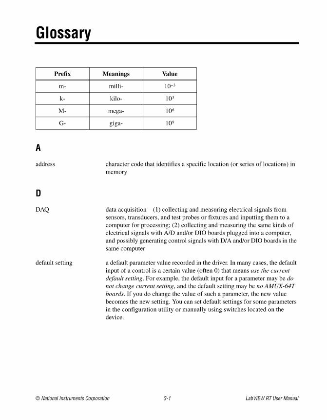
Prefix Meanings Value
m- milli- 10–3
k- kilo- 103
M- mega- 106
G- giga- 109
A
address character code that identifies a specific location (or series of locations) inmemory
D
DAQ data acquisition—(1) collecting and measuring electrical signals fromsensors, transducers, and test probes or fixtures and inputting them to acomputer for processing; (2) collecting and measuring the same kinds ofelectrical signals with A/D and/or DIO boards plugged into a computer,and possibly generating control signals with D/A and/or DIO boards in thesame computer
default setting a default parameter value recorded in the driver. In many cases, the defaultinput of a control is a certain value (often 0) that means use the currentdefault setting. For example, the default input for a parameter may be donot change current setting, and the default setting may be no AMUX-64Tboards. If you do change the value of such a parameter, the new valuebecomes the new setting. You can set default settings for some parametersin the configuration utility or manually using switches located on thedevice.

Glossary
LabVIEW RT User Manual G-2 ni.com
device a plug-in data acquisition board, card, or pad that can contain multiplechannels and conversion devices. Plug-in boards, PCMCIA cards, anddevices such as the DAQPad-1200, which connects to your computerparallel port, are all examples of DAQ devices. SCXI modules are distinctfrom devices, with the exception of the SCXI-1200, which is a hybrid.
drivers software that controls a specific hardware device such as a DAQ board ora GPIB interface board
H
h hour
hardware the physical components of a computer system, such as the circuit boards,plug-in boards, chassis, enclosures, peripherals, and cables
host PC the computer on which the LabVIEW RT Development System is used todevelop and target VIs to RT Series hardware
Hz hertz—the number of scans read or updates written per second
I
I/O input/output—the transfer of data to/from a computer system involvingcommunications channels, operator interface devices, and/or dataacquisition and control interfaces
K
k kilo—the standard metric prefix for 1,000, or 103, used with units ofmeasure such as volts, hertz, and meters
K kilo—the prefix for 1,024, or 210, used with B in quantifying data orcomputer memory
kbytes/s a unit for data transfer that means 1,000 or 103 bytes/s
Glossary
© National Instruments Corporation G-3 LabVIEW RT User Manual
L
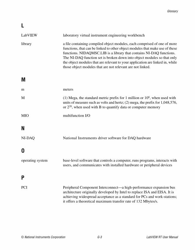
LabVIEW laboratory virtual instrument engineering workbench
library a file containing compiled object modules, each comprised of one of morefunctions, that can be linked to other object modules that make use of thesefunctions. NIDAQMSC.LIB is a library that contains NI-DAQ functions.The NI-DAQ function set is broken down into object modules so that onlythe object modules that are relevant to your application are linked in, whilethose object modules that are not relevant are not linked.
M
m meters
M (1) Mega, the standard metric prefix for 1 million or 106, when used withunits of measure such as volts and hertz; (2) mega, the prefix for 1,048,576,or 220, when used with B to quantify data or computer memory
MIO multifunction I/O
N
NI-DAQ National Instruments driver software for DAQ hardware
O
operating system base-level software that controls a computer, runs programs, interacts withusers, and communicates with installed hardware or peripheral devices
P
PCI Peripheral Component Interconnect—a high-performance expansion busarchitecture originally developed by Intel to replace ISA and EISA. It isachieving widespread acceptance as a standard for PCs and work-stations;it offers a theoretical maximum transfer rate of 132 Mbytes/s.

Glossary
LabVIEW RT User Manual G-4 ni.com
PID control a three-term control mechanism combining proportional, integral, andderivative control actions. Also see proportional control, integral control,and derivative control.
protocol the exact sequence of bits, characters, and control codes used to transferdata between computers and peripherals through a communicationschannel, such as the GPIB bus
R
RAM random-access memory
real time a property of an event or system in which data is processed as it is acquiredinstead of being accumulated and processed at a later time
S
s seconds
S samples
shared memory memory that can be sequentially accessed by more than one controller orprocessor but not simultaneously accessed. Also known as dual-modememory.
soft reboot restarting a computer without cycling the power, usually through theoperating system
synchronous (1) hardware—a property of an event that is synchronized to a referenceclock; (2) software—a property of a function that begins an operation andreturns only when the operation is complete
U
update the output equivalent of a scan. One or more analog or digital outputsamples. Typically, the number of output samples in an update is equal tothe number of channels in the output group. For example, one pulse fromthe update clock produces one update which sends one new sample to everyanalog output channel in the group.

Glossary
© National Instruments Corporation G-5 LabVIEW RT User Manual
V
V volts
VI virtual instrument—(1) a combination of hardware and/or softwareelements, typically used with a PC, that has the functionality of a classicstand-alone instrument; (2) a LabVIEW software module (VI), whichconsists of a front panel user interface and a block diagram program

© National Instruments Corporation I-1 LabVIEW RT User Manual
Index
AApplication Builder, for stand-alone
applications, 3-3 to 3-5architecture of LabVIEW RT, 1-2 to 1-6
overview, 1-2 to 1-4RT Development System, 1-4 to 1-5RT Engine, 1-5 to 1-6
array copying, avoiding, 4-5
BBuild Application dialog box, 3-4
Ccommunicating using host LabVIEW
applications, 3-9 to 3-11shared memory (RT Series DAQ devices
only), 3-10 to 3-11TCP/IP, 3-9VI Server, A-10
communication overview, 1-3computer platform. See target platform.conventions used in manual, viicreating stand-alone applications, 3-3 to 3-5customer education, A-1
DDAQ devices
in LabVIEW RT architecture (figure), 1-4overview, 1-2shared memory (RT Series DAQ devices
only), 3-10 to 3-11date/time functions on RT Engine, 1-5 to 1-6
debugging LabVIEW RT VIs, 3-3distributed computing with VI Server, 3-10documentation
conventions used in manual, viirelated documentation, viii
downloading VIs, 3-2 to 3-3
Eexecution target. See target platform.
Hhost LabVIEW applications. See communicating
using host LabVIEW applications.
Iinstallation of LabVIEW RT software, 2-1
LLabVIEW RT. See also programming; RT
Development System; RT Engine.architecture, 1-2 to 1-6components, 1-1 to 1-4
networked RT series devices(figure), 1-4
RT series DAQ devices (figure), 1-4three components (figure), 1-3
creating stand-alone applications, 3-3 to 3-5debugging LabVIEW RT VIs, 3-3downloading VIs, 3-2 to 3-3installation, 2-1launching, 3-1 to 3-2

Index
LabVIEW RT User Manual I-2 ni.com
networked RT series devices, 1-2plug-in RT series DAQ devices, 1-2real-time features of LabVIEW RT
environment, 4-2system time and local time on RT
Engine, 1-5 to 1-6launching LabVIEW RT, 3-1 to 3-2local time on RT Engine, 1-5 to 1-6loops, efficient, 4-4 to 4-5
avoiding array copying, 4-5improving DAQ configuration, 4-4removing redundant operations, 4-4setting priorities of subVIs, 4-4 to 4-5
Mmanual. See documentation.
Nnetworked RT series devices
in LabVIEW RT architecture (figure), 1-4overview, 1-2
NI Developer Zone, A-1
Ooperating LabVIEW RT
creating stand-aloneapplications, 3-3 to 3-5
debugging LabVIEW RT VIs, 3-3downloading VIs, 3-2 to 3-3launching, 3-1 to 3-2
Pplatform. See target platform.plug-in RT series DAQ devices
in LabVIEW RT architecture (figure), 1-4overview, 1-2
shared memory (RT Series DAQ devicesonly), 3-10 to 3-11
programming, 3-5 to 3-11communicating using host LabVIEW
applications, 3-9 to 3-11shared memory (RT Series DAQ
devices only), 3-10 to 3-11TCP/IP, 3-9VI Server, 3-10
overview, 3-5real-time programming, 4-1 to 4-5
performance of LabVIEW RTVIs, 4-3 to 4-5
real-time features of LabVIEW RTenvironment, 4-2
real-time performance ofVIs, 4-1 to 4-3
running VIs at time-criticalpriority, 4-2 to 4-3
time-critical priority, 4-1writing efficient loops, 4-4 to 4-5
RT Development System, 3-6 to 3-11acquiring RT Engine
information, 3-6connecting to RT Engine with VIs
already running, 3-7 to 3-8exiting, 3-8switching LabVIEW RT execution
targets, 3-7
Rreal-time programming, 4-1 to 4-5
performance of LabVIEW RTVIs, 4-3 to 4-5
real-time features of LabVIEW RTenvironment, 4-2
real-time performance of VIs, 4-1 to 4-3running VIs at time-critical priority
in RT Development System,4-2 to 4-3
Index
© National Instruments Corporation I-3 LabVIEW RT User Manual
without RT DevelopmentSystem, 4-3
time-critical priority, 4-1writing efficient loops, 4-4 to 4-5
RT Development System, 3-6 to 3-11acquiring RT Engine information, 3-6advantages and disadvantages, 3-6connecting to RT Engine with VIs already
running, 3-7 to 3-8description, 1-4 to 1-5exiting, 3-8in LabVIEW RT architecture, 1-4 to 1-5running VIs at time-critical
priority, 4-2 to 4-3switching LabVIEW RT execution
targets, 3-7RT Engine
acquiring RT Engine information, 3-6connecting to RT Engine with VIs already
running, 3-7 to 3-8description, 1-5in LabVIEW RT architecture, 1-5 to 1-6system time and local time on
RT Engine, 1-5 to 1-6
Sshared memory, 1-3, 3-10 to 3-11software installation, 2-1stand-alone applications, creating, 3-3 to 3-5starting LabVIEW RT, 3-1 to 3-2switching execution targets, 3-7system integration, by National
Instruments, A-1system time/local time on RT Engine,
1-5 to 1-6
Ttarget platform
selecting, 3-1 to 3-2switching execution targets, 3-7
TCP/IP protocol, 3-9technical support resources, A-1 to A-2time, system and local, 1-5 to 1-6time-critical priority. See real-time
programming.
VVI Server for distributed computing, 3-10VIs
Changed or Missing VIs dialog box, 3-8connecting to RT Engine with VIs already
running, 3-7 to 3-8debugging LabVIEW RT VIs, 3-3downloading, 3-2 to 3-3performance of LabVIEW RT
VIs, 4-3 to 4-5Reset checkbox in Select Target Platform
dialog box (note), 3-7writing efficient loops, 4-4 to 4-5
avoiding array copying, 4-5improving DAQ configuration, 4-4removing redundant operations, 4-4setting priorities of subVIs,
4-4 to 4-5
WWeb support from National Instruments, A-1Worldwide technical support, A-2writing efficient loops, 4-4 to 4-5