teacher/mentor institute using easyc joel kirkland july 30-31, 2015
TRANSCRIPT

Teacher/Mentor Institute
Using easyC
Joel KirklandJuly 30-31, 2015

Outline
Intro to Programming (or Coding) Intro to easyC easyC user interface (IDE) Basic example program Debugging Tips Additional TMI easyC Training
Breakout sessions on Friday – Intro and Advance
Charts for Hands-On Session: Building a Robot Intro
Additional charts in TMI Notebook 1 hour easyC Breakout session at Kickoff for
Teachers, Mentors and Students
Page 2

Programming Overview
Connects inputs to robot outputs Read Joystick or sensors (inputs) Determines when and how motors
and servos operate (outputs) Program structure uses decision and
logic statements to determine robot responses
Used to fit the requirements of the game and your robot design

Traditional Syntax
Traditional C syntax can be imposing
Program structure is not obvious without experience
Page 4
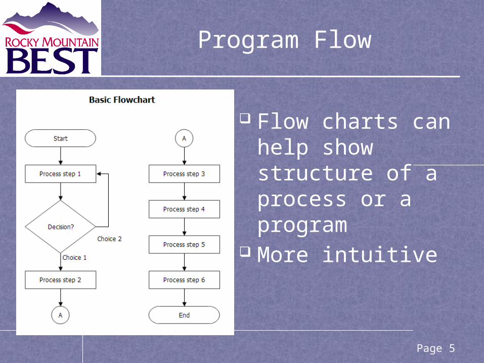
Program Flow
Flow charts can help show structure of a process or a program
More intuitive
Page 5

easyC Example
• Combines both graphical and textual representations of code
• easyC is a simpler version of the C programming language for the VEX Cortex with graphical, drag and drop interface Page 6

easyC User Interface (IDE)
Menus
Function
Blocks
Icons
Project Explorer
Page 7
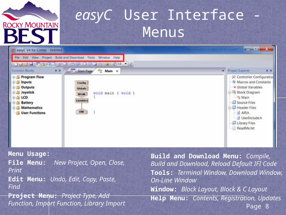
easyC User Interface - Menus
Menu Usage: File Menu: New Project, Open, Close, Print Edit Menu: Undo, Edit, Copy, Paste, Find Project Menu: Project Type, Add Function, Import Function, Library Import
Build and Download Menu: Compile, Build and Download, Reload Default IFI Code Tools: Terminal Window, Download Window, On-Line Window Window: Block Layout, Block & C Layout Help Menu: Contents, Registration, Updates
Page 8

easyC User Interface - Icons
Icons
New Project
New Competition
Project
Open
Save
Start Page Enable
Function Blocks Enable
Project Explorer Enable
Output Panel Enable
Controller Configuration
Global Variables
Compile
Compile and
Download
Terminal Window
Graphic Display
On-line Window
Find
Zoom
Page 9
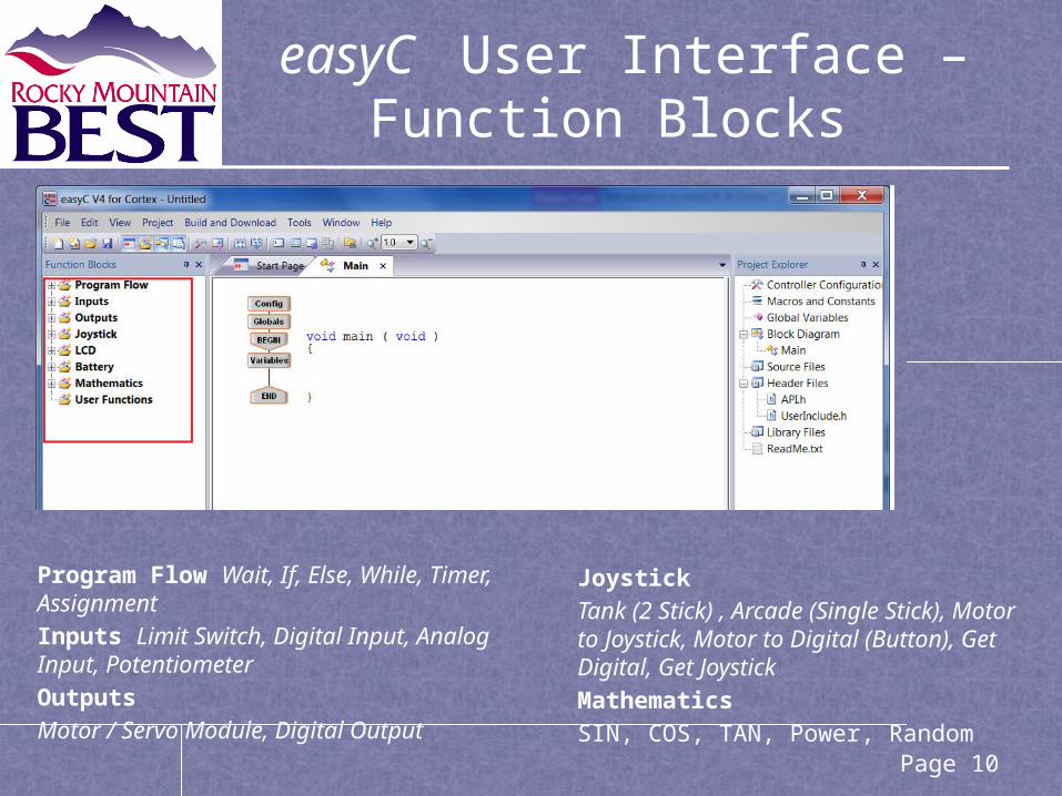
easyC User Interface – Function Blocks
Program Flow Wait, If, Else, While, Timer, Assignment Inputs Limit Switch, Digital Input, Analog Input, Potentiometer Outputs Motor / Servo Module, Digital Output
Joystick Tank (2 Stick) , Arcade (Single Stick), Motor to Joystick, Motor to Digital (Button), Get Digital, Get Joystick Mathematics SIN, COS, TAN, Power, Random
Page 10

easyC User Interface - Project Explorer
Advance Capabilities:Controller Configuration Change Inputs and Output, Label Ports Macros and Constants Create Definitions (aka C #define) Global Variables Variable with Global Program Scope
Block Diagram Select Between Functions Source & Header Files Create or Import .c and .h files, Write C-Code Freehand Library Files Import a easyC® library
Page 11
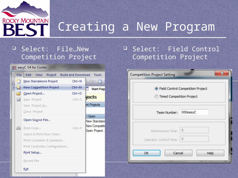
Creating a New Program
Select: File…New Competition Project
Select: Field Control Competition Project
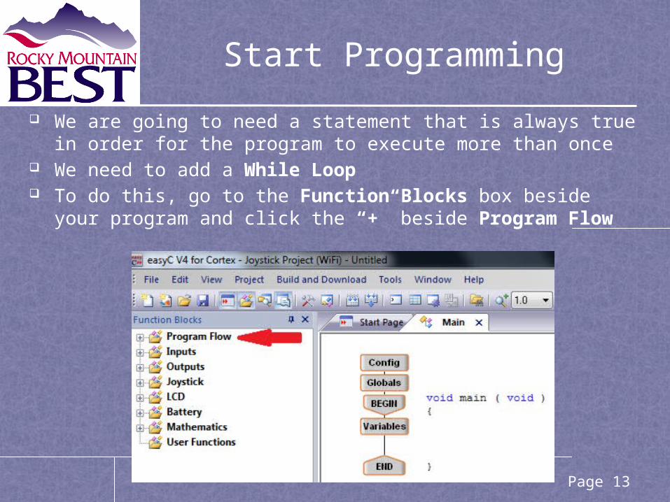
We are going to need a statement that is always true in order for the program to execute more than once
We need to add a While Loop To do this, go to the Function Blocks box beside your
program and click the “+” beside Program Flow
Start Programming
Page 13

Simple Program Example
• This simple program can be modified to add additional motors and/or servos
• The remaining charts describe the creation of this program
Page 14

Then click and drag While Loop from the list and place it on the vertical line between Variables box and End box.
At this point a dialog box appears Type a true expression
such as (2<3) or 1 Click OK
While Loop
Page 15
While Loop Example
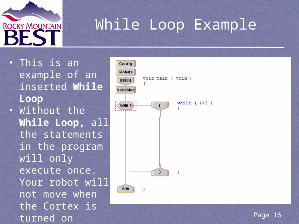
• This is an example of an inserted While Loop
• Without the While Loop, all the statements in the program will only execute once. Your robot will not move when the Cortex is turned on
Page 16

Inside the While Loop a set of brackets appear, this is where you add additional statements
First add a motor to the program Click the “+” beside Joystick under the
Function Blocks Click and drag the Joystick To Motor function
to the vertical line between the brackets in your While Loop
When you do this, a dialog box appears which is displayed on the next page
Motor Programming (1 of 2)
Page 17

The Joystick to Motor dialog box for Motor Selection: We can not use Motor
1 in the competition For this example we
will use Motor 2 Click on the down
arrow in the motor box and select Motor 2
Motor Numbers 1 and 10 are not permitted for use in competition and are not used in the program
Motor Programming (2 of 2)
Page 18

Transmitter is always set to Joystick # 1 Transmitter Channel allows you to select which
buttons or joysticks on the Joystick Controller you want to use for a specific purpose In this program we are going to use the left hand joystick
to operate the wheels and the right hand joystick to operate an arm and a claw
We can also change the Channel the same way as we changed the Motor For this example we will use Channel 1 Which just so happens to be the default Finally click Ok
You can create as many motor functions as you need for your program.
Joystick Transmitter Channel
Page 19

You will use the Channel 1 on the Joystick Controller to operate the motor
Move the Right Joystick left or right to control the Motor
Using the Joystick Controller – Channel 1
Page 20

One of the most commonly used wheel configurations is a wheel on each side of the robot
To avoid spinning in circles, the motors need to spin in opposite directions
The wheels need to spin at the same rate (move the robot straight forward and backward) and spin at different rates (turn the robot)
This can be achieved in an Arcade Function
Creating a Program for Wheels
Page 21

Arcade Drive Example(page 1 of 2)
This function drives a robot with motors connected to motor numbers 2 (left) and 3 (right), using joystick channels 2 (left stick vertical) and 1 (right stick horizontal)
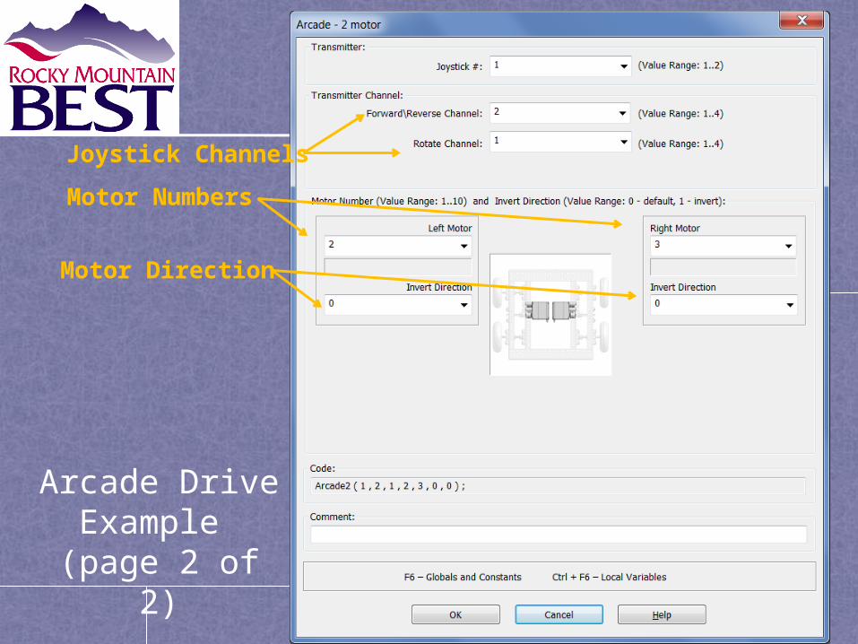
Arcade Drive Example
(page 2 of 2)
Motor Numbers
Joystick Channels
Motor Direction

To operate the wheels properly the direction of one of the motors needs to reversed (aka inverted) Invert Direction for Left Motor 6 by clicking the
down arrow of Invert Direction and selecting 1 If the robot goes backwards, change Invert
Direction of Left Motor 6 to 0 and select 1 under Invert Direction for Right Motor 8
Finally click OK The motor direction may also be changed by
reversing the leads on the motor
Arcade Programming - Invert Direction of Motors
Page 24

To operate a servo with the Joystick Controller Go back to Joystick in the Function Block Click and drag the Joystick to Servo function to
your While Loop and place it on the vertical line between the JoystickToMotor function box and the lower bracket box
When you do this, another dialog box will appearo Except for the Servo title, it looks identical to the
Motor Dialog Box For the example program
Set the Channel to 2 and the Motor to 4 the same way as the Motor was configured
Click OK
Servo Programming
Page 25

Simple Program Example
• This simple program demonstrates most of the functionality used to control your Mini-Robot
• Additional training later in the workshop
• Kickoff event includes an hour training session for your students.
Page 26

easyC On-Line Window
The easyC On-Line Window allows the user to see and control motors and sensors attached to the robot in real time. This can be enabled at any time.
Note: The On-Line Window requires a program, even blank, be downloaded after updating the master firmware.
Page 27
Debugging Tip: Can be used to identify & correct errors with input and output assignment or wiring

easyC Terminal Window
The easyC allows users to see output from PrintToScreen calls form within their program while the program is running on the Cortex
Page 28
Debugging Tip: Printing to screen helps to provide feedback internal state

easyC Terminal Window
The easyC allows users to see output from GraphicDisplay calls form within their program while the program is running on the Microcontroller. The Graphic Display is a more advanced type of feedback that allows values to placed on grid instead of scrolling.
See Samples –> “Graphic Display Joystick Test” for code.
Page 29
Debugging Tip: Similar to printing but provides a continuous display of internal program variables/inputs/outputs