te809-ats - tecnoelettra · te809ats-en-v2.0.doc page 7/48 1- 5.2 connections j1 – genset ac...
TRANSCRIPT

TE809Ats-EN-v2.0.doc Page 1/48
PREFACE Thanking you for preference, TECNOELETTRA SRL hopes that the use of this equipment could be a reason of satisfaction. This manual is designed to put you in a position to intervene on the equipment and different performs of installation and connection. In order to ensure efficient operation and durability, it is recommended the strict observance of the rules laid down here. Thanks in advance for the suggestions that we will be given to possible further improvements of the equipment. For any question always consult the TECNOELETTRA Technical Department. TECNOELETTRA S.r.l. Note: The manufacturer reserves the right to modify equipment for any manufacturing or commercial need, without the obligation to promptly update this installation and using manual. This manual cannot be modified without authorization by TECNOELETTRA. This material is the exclusive property of TECNOELETTRA, and cannot be used or disclosed for purposes other than those contractual.
TE809-Ats Instruction s Manual
Project: v2.0

TE809Ats-EN-v2.0.doc Page 2/48
INDEX
1- GENERAL REQUIREMENTS AND INSTALLATION................... ........................................................................................3 1- 1 General notes .................................................................................................................................................................................. 3 1- 2 Product Label and Rating plate ..................................................................................................................................................... 3 1- 3 TE809 2.0 New features .................................................................................................................................................................. 4 1- 4 Hardware ratings ............................................................................................................................................................................. 5 1- 5 Electrical Installations .................................................................................................................................................................... 6
1- 5.1 Drawing ...........................................................................................................................................................................................................6 1- 5.2 Connections ....................................................................................................................................................................................................7
1- 6 Operation modes ............................................................................................................................................................................ 8 1- 6.1 Automatic mode ..............................................................................................................................................................................................8 1- 6.2 Manual mode ...................................................................................................................................................................................................8 1- 6.3 Reset mode .....................................................................................................................................................................................................8 1- 6.4 Test mode ........................................................................................................................................................................................................8 1- 6.5 Alarms .............................................................................................................................................................................................................8
1- 7 Equipment Overview ...................................................................................................................................................................... 9 1- 8 Display pages ................................................................................................................................................................................ 10
1- 8.1 Navigation diagram ....................................................................................................................................................................................... 10 1- 8.2 Navigation cursors and first activation ........................................................................................................................................................ 11 1- 8.3 Display pages - Mains ................................................................................................................................................................................... 12 1- 8.4 Display pages - Genset ................................................................................................................................................................................. 12 1- 8.5 Display pages - Engine ................................................................................................................................................................................. 13 1- 8.6 Display pages - Hours .................................................................................................................................................................................. 13 1- 8.7 Display pages - Events log ........................................................................................................................................................................... 13 1- 8.8 Display pages - System ................................................................................................................................................................................ 14 1- 8.9 Clock and warranty ........................................................................................................................................................................................ 14
1- 9 Optional accessories .................................................................................................................................................................... 15 1- 9.1 Serial cable code 95-050 ............................................................................................................................................................................... 15 1- 9.2 GSM modem code 1571806B ........................................................................................................................................................................ 15 1- 9.3 TCP/IP converter Aport code 1571806G ...................................................................................................................................................... 15 1- 9.4 Expansion boards TE6010 ............................................................................................................................................................................ 15
1- 10 Connection via RS485 with TE809G controller .......................................................................................................................... 16
2- PROGRAMMATION MENUS................................. .............................................................................................................17 2- 1 Navigation chart - Global Setup ................................................................................................................................................... 17 2- 2 Navigation instructions ................................................................................................................................................................ 18 2- 3 M1 - Mains setup ........................................................................................................................................................................... 19 2- 4 M2 - Alternator setup .................................................................................................................................................................... 20 2- 5 M3 - Engine setup ......................................................................................................................................................................... 21 2- 6 M4 - General setup ........................................................................................................................................................................ 22
2- 6.1 M4.1 - Display setup ...................................................................................................................................................................................... 22 2- 6.2 M4.2 - Clock setup ........................................................................................................................................................................................ 22 2- 6.3 M4.3 - Test setup ........................................................................................................................................................................................... 23 2- 6.4 M4.4 - Security setup .................................................................................................................................................................................... 24
2- 7 M5 - Alarms list ............................................................................................................................................................................. 25 2- 7.1 M5 - Alarms default parameters ................................................................................................................................................................... 26 2- 7.2 M5 - Alarms description ................................................................................................................................................................................ 27
2- 8 M6 - Special functions .................................................................................................................................................................. 28 2- 8.1 M6.1 - EJP...................................................................................................................................................................................................... 28 2- 8.2 M6.2 - Start by mains kW .............................................................................................................................................................................. 29 2- 8.3 M6.3 - Dummy load ....................................................................................................................................................................................... 29 2- 8.4 M6.4 - TPS ..................................................................................................................................................................................................... 30 2- 8.5 M6.5 - Hours .................................................................................................................................................................................................. 30
2- 9 M7 - Connectivity .......................................................................................................................................................................... 31 2- 9.1 M7.1 - Serial port setup ................................................................................................................................................................................. 31 2- 9.2 M7.2 - GSM Setup .......................................................................................................................................................................................... 32 2- 9.3 M7.3 - Datalogger .......................................................................................................................................................................................... 35
2- 10 M8 - IO setup ............................................................................................................................................................................... 36 2- 10.1 M8.1 - Input setup ....................................................................................................................................................................................... 36 2- 10.2 M8.2 - Output setup ..................................................................................................................................................................................... 37 2- 10.3 M8.3 - Input type .......................................................................................................................................................................................... 39 2- 10.4 M8.4 - Output type ....................................................................................................................................................................................... 39 2- 10.5 M8.5 - Calibration ........................................................................................................................................................................................ 39 2- 10.6 M8.6 - Expansion ......................................................................................................................................................................................... 40 2- 10.7 Expansion board TE6010 ............................................................................................................................................................................ 41
2- 11 - Modbus RTU ........................................................................................................................ Errore. Il segnalibro non è definito. 2- 11.1 General notes ........................................................................................................................................ Errore. Il segnalibro non è definito. 2- 11.2 TE809 Configuration .............................................................................................................................. Errore. Il segnalibro non è definito. 2- 11.3 Modbus commands available ................................................................................................................ Errore. Il segnalibro non è definito.

TE809Ats-EN-v2.0.doc Page 3/48
1- GENERAL REQUIREMENTS AND INSTALLATION
1- 1 General notes
WARNING! • Carefully read the manual before the installation or use. • This equipment is to be installed by qualified personnel, complying to current standards, to avoid damages or safety hazards.
• Before any maintenance operation on the device, remove all the voltages from measuring and supply inputs. • Products illustrated herein are subject to alteration and changes without prior notice. • Technical data and descriptions in the documentation are accurate, to the best of our knowledge, but no liabilities for errors, omissions or
contingencies arising there from are accepted. • A circuit breaker must be included in the electrical installation of the building. It must be installed close by the equipment and within easy reach
of the operator. It must be marked as the disconnecting device of the equipment: IEC /EN 61010-1 § 6.12.2.1. • Clean the instrument with a soft dry cloth; do not use abrasives, liquid detergents or solvents. 1- 2 Product Label and Rating plate
General identifications of each unit are traced on the plate below and placed on the controller.
NOTE!
Inform the manufacturer the general identification data reported on the label, before asking for techn ical specifications or informations about the equipment.
182 mm
245 mm
40 mm
Cut-off dimensions: 220 x 160 mm

TE809Ats-EN-v2.0.doc Page 4/48
1- 3 TE809 2.0 New features
List of new feature inside TE809Ats 2.0 and differences with TE809Ats 1.1.4:
GENERIC FEATURES
1. New parameter to start engine in auto mode for every mains alarm, not only voltage and frequency out of range values 2. Programmable timer start/stop with two separate working periods with day of the week enable 3. Improved feedback inputs 4. Cost per kWh mains and genset 5. Support for single current transformer panels or three current transformer panels 6. Improved leds management 7. Improved automatic warranty detection 8. Software optimization to improve performances
IO OPTIONS
9. External changeover command by programmable input 10. TE6010 expansion support with different configurations of digital inputs and outputs 11. Generator ready to supply load output 12. Single alarm options A-B-C to connect an output to one of 64 alarms
REMOTE CONTROL
13. Compact modbus measures: all reading values with two multiple requests of 44 registers
ANDROID SMS APP
14. Improved SMS features with more INFO values and SMS password 15. Complete support for Android “TE Remote SMS” App by Tecnoelettra

TE809Ats-EN-v2.0.doc Page 5/48
1- 4 Hardware ratings
GENERAL CHARACTERISTICS Rated voltage Vdc 12Vdc (24Vdc) Allowed Vdc from 6Vdc to 33Vdc Rated voltage Vac 400 Vac Allowed Vac Up to 500 Vac Allowed frequency From 45 to 75 Hz Max consumption with backlight 250 mA
-30 °C + 70 °C (electric) -20 °C + 70 °C (display) Temperature range -30 °C + 80 °C (storage)
DISPLAY 128x64 px ; 66x33mm DIGITAL INPUTS N° 5 STATIC OUTPUT N° 6 (2x4A ; 4x2A) SERIAL COMMUNICATION INTERFACE Interface type Serial RS -232 Cable length < 3 m Baud rate Up to 115200 bps Interface type Serial RS485 Baud rate Up to 115200 bps CONTACTORS RELAYS N° outputs 2 Type of contacts 1x N.O. genset contactor - 1x N.C. mains contactor Contatcs capacity 8 A / 250 VAC LOAD CURRENTS INPUT N° 3 Measure range Up to 5A Precision < 1% F.S. + 1 digit * VOLTAGE INPUTS N° 8 Input type Resistive coupling Rated voltage 230 Vac (L-N) - 400 Vac (L-L) Measure range TRMS from 0 to 300 Vac (L-N) - from 0 to 500 Vac (L-L) Precision < 1% F.S. + 1 digit ACTIVE POWER MEASURE Measure type Instant power integration Precision < 1% HARDWARE N°Keys 13 N°LED 10
STANDARD REFERENCE EN55011 EN55016-2-1 EN55016-2-3 EN60068-2-1 EN60068-2-2 EN60068-2-27 EN60068-2-30 EN60068-2-6 EN61000-4-2 EN61000-4-3 EN61000-4-4 EN61000-4-5 EN61000-4-6 EN61000-4-8 EN61000-6-2 EN61000-6-4 HBV Bureau Veritas NR320
* CURRENT MEASURES
300 mA 4A 5A
5A*CT ratio
4A*CT ratio
CONTROLLER MEASURES
300mA*CT ratio
Precision: 1% F.S.
CT SECONDARY
Precision: 2% F.S.

TE809Ats-EN-v2.0.doc Page 6/48
1- 5 Electrical Installations
1- 5.1 Drawing
Warning! Before inserting the plugs and supply the board, make sure that the connections strictly comply with the wiring diagram below.
ts

TE809Ats-EN-v2.0.doc Page 7/48
1- 5.2 Connections
J1 – Genset AC voltage and contactors 1.1 - Mains contactor output (NC) 1.2 - Mains contactor output (NC) 1.3 - Genset contactor output (NO) 1.4 - Genset contactor output (NO) 1.5 - Genset voltage phase 1 1.6 - Genset voltage phase 2 1.7 - Genset voltage phase 3 1.8 - Neutral
J2 – Mains AC voltage 2.1 - Mains voltage phase 1 2.2 - Mains voltage phase 2 2.3 - Mains voltage phase 3 2.4 - Neutral
J5 – Supply and Outputs 5.1 - Battery negative 5.2 - Battery positive 5.3 - Common positive for the relay outputs 5.4 - Programmable output (default – Start) 5.5 - Programmable output (default – Faulty start) 5.6 - Not used 5.7 - Not used 5.8 - Programmable output (default – Global alarm #1) 5.9 - Programmable output (default – Auto mode) 5.10 - Programmable output (default – Manual mode) 5.11 - Programmable output (default – Siren)
RS232 - Communication ports RS232 - connection of a remote device
J8 - RS485 port 1- Shield 2- A 3- B 4- Termination resistor
J3 – Genset AC current 3.1 - Genset current I1 3.2 - Genset current I2 3.3 - Genset current I3 3.4 - CT common
J4 – Digital inputs 4.1 - Gnd 4.2 - Gnd 4.3 - Gnd 4.4 - Programmable digital input (default – Electrical Trip) 4.5 - Programmable digital input (default – Ground protection) 4.6 - Programmable digital input (default – Remote start) 4.7 - Programmable digital input (default – Remote stop) 4.8 - Programmable digital input (default – Ext. GE protection)

TE809Ats-EN-v2.0.doc Page 8/48
1- 6 Operation modes
At the power on, the TE809 is in reset mode. With the buttons you can choose the functioning mode you prefer. 1- 6.1 Automatic mode
Push the AUT button to select this functioning mode. In case of mains failure the remote start output (J5.4) is activated and is de-activated in the presence of the same. This is the standard logic. It’s also possible to activate the remote start output in special conditions. For more informations see the special functions menu M6. 1- 6.2 Manual mode
In this operative mode, to turn-on the generator (activating the remote start output) you must press KG button. With engine running, you can manually command the transfer switching with KG and KR buttons. KR, besides transferring the load on mains side, turns off the generator. Pressing and releasing quickly the KR button, KG is opened and the remote start output is deactivated after the cooling time; keeping pressed for 3 seconds KR button, KG is opened and the generator is stopped immediately. 1- 6.3 Reset mode
The remote start output cannot be activated. If the mains is available it is connected to the load. If you select Reset mode, the alarms are reset and the remote start output is deactivated. If the cause of the alarm remains, the cause is still present. Push the RESET button to select this functioning mode.
1- 6.4 Test mode
Manual test: Press the TEST button: the remote start output is activated to test the genset for a programmable time.
a) If activated during MAN mode, the load switching can be controlled only by KG and KR buttons, even if the mains is faulty. Disabling the test (or after the test time), the controller returns to the previous operation mode.
b) If activated during the AUT mode, the test can be made with or without load, depending on the programmation of the test setup (see menu M4.3).
Automatic test: If you programmed an automatic test (see menu M4.3), it will run only if you are in automatic mode. The test can be made with or without load, depending on the programmation of the test setup (see menu M4.3).
1- 6.5 Alarms
In case of alarm, the display shows its description. If more different alarms are detected, they appear individually in sequence. For each alarm it is available a message that can help to identify the source of the problem. The alarm reset can be made by pressing the RESET button; by this, the alarm is deleted and the TE809 goes in Reset mode, preventing accidental generator starting attempts. If the alarm, after reset, still remains on the display, the cause of the alarm is not removed.

TE809Ats-EN-v2.0.doc Page 9/48
1- 7 Equipment Overview
POS. NAME DESCRIPTION
A Display Backlighted display that shows all functions, measures and alarms about the generator and the mains. Automatically the backlight turns off, and it turns on again when you press a button.
B AUT Button to select the automatic mode. C TEST Button to select the test mode.
D RESET To activate reset/OFF mode. In this operative mode the remote start output is deactivated and the alarms are deleted. If the cause of the alarm persists, the alarm will appear again.
E KG Key control to activate the remote start output (only in manual mode). With engine running, and in manual test mode, this button permits to manage the generator contactor.
F Menu To enter the programmation menu. Inside the menus, it’s used as a button “back” or “esc”. G KG state led Led that indicates if KG is closed (led on) or open (led off). H KR state led Led that indicates if KR is closed (led on) or open (led off).
I Help From the main page of the menu, it permits to go directly to the active alarms page, if at least one alarm is present.
J KR Key control to deactivate the remote start output (only in manual mode). If it’s pressed and released quickly, it deactivates the output after the cooling time; if it’s keeped pressed for 3 seconds, it deactivates the output immediately. In manual test mode, this button permits to manage the mains contactor.
K MAN Button to select the manual mode.
L Navigation drive
Navigation drive composed by 4 arrows to scroll through the pages (left and right arrows) and increase or decrease the parameters inside the programmation menus. It contains also a special button “i”, to select an element on the screen or edit a parameter and confirm the new value. See paragraph 1.8.1 for more informations about the navigation of the display pages, and paragraph 2-2 for more informations about the navigation through the menus.
M Mains state led
It shows if the mains status: • led OFF if mains not detected • led blinking if mains detected outside limits • led ON if mains is within limits after delay
N Generator state led
It shows the status of the generator: • led OFF if genset is not detected • led blinking if genset is running but not within limits • led ON if genset is within limits after delay
O General alarm led It blinks if a stopping alarm is present. It remains ON if an alarm enabled as global alarm 1 is present. P Battery state led It turns on when the board is supplied.
B
A
D
E
K
C
G F J I H
L
M
N
O
P

TE809Ats-EN-v2.0.doc Page 10/48
1- 8 Display pages
1- 8.1 Navigation diagram
When you turn on the board, you will see the logo page. Then you will be in the mains stand-by page. When you start the generator, you will go in the genset stand-by page. When you stop the engine you will return automatically to the mains stand-by page. With the left and right arrows, you can move through the different sections, and with the up and down arrows you can scroll the pages of the selected section. Pressing the “i” button from navigation pages, you can go to the status and alarm page. Here you can see the organization diagram of the display pages.
Notes : Pages Mains 1,2,3,4 are shown only if parameter M in menu M1 is set to “Three-phase”. Pages Genset 1,2,3,4 are shown only if parameter M in menu M2 is set to “Three-phase”. Page Engine is shown only if the communication with TE809G is enabled inside menu M7.1
START
DOWN ARROW
Logo
ON
5 sec
STOP
MAINS 1 GENSET 1
HOURS EVENTS I/O DIGITAL
MAINS 2
MAINS 3
MAINS 4
kWh
GENSET 2
GENSET 3
GENSET 4
kWh
I/O ANALOG
DATASYS
Generator OK
STARTING
Stop OK
STOPPING
MAINS STANDBY
i
LEFT ARROW
RIGHT ARROW
UP ARROW
EXPANSION INPUTS
EXPANSION OUTPUTS
MAINS STANDBY
GENSET SUMMARY
ALARMS
CLOCK / WARRANTY
ENGINE

TE809Ats-EN-v2.0.doc Page 11/48
1- 8.2 Navigation cursors and first activation
o The cursors on the upper side and left side of the display indicate the position of the page inside the navigation diagram: the left and right arrows move the page along with horizontal cursor.
o The left arrow button allows to return back to the previous section: in this case from the generator pages to the mains pages.
o If the vertical cursor is available on display it’s possible to use up and down arrow buttons to see more pages for the section: in this case from the mains measure #1 to mains measure #2.
o With up arrow button you can return to the previous page of the section, in this case from fuel control #2 to fuel control #1. Inside the main page there is also the horizontal cursor which means that the left and right arrow buttons are available.
o In some of the main pages there isn’t the vertical cursor. In this case up and down arrow buttons command the selection cursor in the same way as setup pages.
o When the controller is activated for the first time, the language selection screen will appear. If a language different from “DEFAULT” is selected, this screen will not appear anymore at the next startup.

TE809Ats-EN-v2.0.doc Page 12/48
1- 8.3 Display pages - Mains
1- 8.3.1 Mains stand-by
When you turn on the board, you will see the logo page. After 5 seconds you will be in this page, that is the stand-by page with engine OFF:
A) Mains Vac voltage L1-L2 (or L1-N if the system is single-phase)
B) Mains L1 current C) Total kW on mains D) Total kVA on mains E) Total power factor F) Mains frequency
1- 8.3.2 Mains 1
(shown only in case of 3-phase system)
A) Mains Vac voltages L1-L2-L3 B) Mains line voltages L1-L2-L3 C) Mains currents L1-L2-L3 and total
1- 8.3.3 Mains 2
(shown only in case of 3-phase system)
A) Mains apparent power L1-L2-L3 and total B) Mains active power L1-L2-L3 and total C) Mains reactive power L1-L2-L3 and total
1- 8.3.4 Mains 3
(shown only in case of 3-phase system)
A) Mains apparent power L1-L2-L3 and total B) Mains active power L1-L2-L3 and total C) Power factor L1-L2-L3 and total
1- 8.3.5 Mains 4
(shown only in case of 3-phase system)
A) Mains apparent power L1-L2-L3 and total B) Mains reactive power L1-L2-L3 and total C) Power factor L1-L2-L3 and total
1- 8.3.6 Mains control kWh
A) Total active energy supplied by mains B) Total mains energy cost C) Cost of each mains MWh
1- 8.4 Display pages - Genset
1- 8.4.1 Genset summary
A) Genset Vac voltage L1-L2 (or L1-N if the system is single-phase)
B) Genset L1 current C) Total kW on genset D) Total kVA on genset E) Total power factor F) Genset frequency
1- 8.4.2 Genset 1
(shown only in case of 3-phase system)
A) Generator Vac voltages L1-L2-L3 B) Generator line voltages L1-L2-L3 C) Generator currents L1-L2-L3
A
B
C
D
E
F
A
B
C
A
B
C
A
B
C
A
B
C
A B
C
A
B
C
D
E
F
A
B
C

TE809Ats-EN-v2.0.doc Page 13/48
1- 8.4.3 Genset 2
(shown only in case of 3-phase system)
A) Generator apparent power L1-L2-L3 and total B) Generator active power L1-L2-L3 and total C) Generator reactive power L1-L2-L3 and total
1- 8.4.4 Genset 3
(shown only in case of 3-phase system)
A) Generator apparent power L1-L2-L3 and total B) Generator active power L1-L2-L3 and total C) Generator power factor L1-L2-L3 and total
1- 8.4.5 Genset 4
(shown only in case of 3-phase system)
A) Generator apparent power L1-L2-L3 and total B) Generator reactive power L1-L2-L3 and total C) Generator power factor L1-L2-L3 and total
1- 8.4.6 Genset control kWh
A) Total active energy supplied by generator (upgraded every work hour with KG closed)
B) Total generator energy cost C) Cost of each generator MWh
1- 8.5 Display pages - Engine
A) Total work hours of the generator B) Battery voltage of the generator C) Hours left to service D) Oil pressure E) Engine temperature F) Fuel level percentage
Note: this page is shown only if parameter B inside menu M7.1 is set to “Modbus Master” and parameter I is set to “On”.
1- 8.6 Display pages - Hours
A) Total work hours of the generator B) Total work hours with KG closed and load > 0 C) Total work hours with KR closed and load > 0
1- 8.7 Display pages - Events log
The events log page shows you the last alarms with the date and time.
A) First event inside selected page: each event records alarm ID, alarm name, date and hour. B) Second event inside selected page. C) Press the UP or DOWN button to select the up or down arrow, then press “ I ”. This way you can scroll the events (up to 250).
A
B
C
A
B
C
A
B
C
A
B C
A
B
C
D
E
F
A
B
C
A
B C

TE809Ats-EN-v2.0.doc Page 14/48
1- 8.8 Display pages - System
1- 8.8.1 I/O digital
In this page you can see the state of all the 5 digital inputs (from J4.4 to J4.8) and outputs KG (J1.4), KR (J1.1), plus 6 programmable outputs (from J5.8 to J5.11, J5.4 and J5.5). 1- 8.8.2 I/O analog
In this page you can see the state of 8 analog inputs (mains voltages excluded). 1- 8.8.3 Expansion inputs
Here you can see the state of the 8 digital inputs of the expansion board (only with expansion enabled). 1- 8.8.4 Expansion outputs
Here you can see the state of the 8 digital outputs of the expansion board (only with expansion enabled).
1- 8.8.5 Data info
This page contains the the information about the release file: REL: Project release version FW: Firmware release version SW: TE Utilities release version DA: Release date
1- 8.9 Clock and warranty
A) Clock: date and time B) Controller warranty expiry date detected automatically by
controller after 2 hours with mains voltage and frequency within limits
A
B

TE809Ats-EN-v2.0.doc Page 15/48
1- 9 Optional accessories
1- 9.1 Serial cable code 95-050
This cable is used to connect your TE809 with a PC for the remote control. It’s a db9 female - db9 female null modem cable.
1- 9.2 GSM modem code 1571806B
This GSM/GPRS modem is used for GSM or GPRS communication. For GSM communication, you need to connect it to the TE809. For the GPRS data transferring it’s necessary to connect one modem to the PC and one to the TE809. In both cases, the connection must be done with a normal male-female 9 poles serial cable (code 51C3).
1- 9.3 TCP/IP converter Aport code 1571806G
It’s possible to connect the TE809 with a TCP/IP converter (to one serial port) to permit the remote monitoring of the controller for example with our TE Monitor.
1- 9.4 Expansion boards TE6010
It’s possible to connect one or more expansion boards to the TE809 to the RS232 or RS485 port. For more informations see paragraph 2- 10.7.
TE6010 base: base board for the connection of I/O TE6010B: 8 digital inputs expansion TE6010C: 5 relay outputs TE6010M: 8 digital outputs expansion

TE809Ats-EN-v2.0.doc Page 16/48
1- 10 Connection via RS485 with TE809G 2.0 controlle r
It’s possible to connect the TE809ATS with a TE809G 2.0 controller via RS485. This way it’s possible to read the most important measures and alarms directly by the TE809Ats controller, and command the starting and stopping of the genset via RS485, without other external connections.
The connection can be done following the drawing:

TE809Ats-EN-v2.0.doc Page 17/48
2- PROGRAMMATION MENUS
2- 1 Navigation chart - Global Setup
Direct to parameters
Direct to parameters
M4.1 – Display setup M4.2 – Clock
setup
M4.3 – Test setup M4.4 – Setup
Security
Alarm category setup
M7.1 – Serial port setup M7.2 – GSM
setup
M8.1 – Input setup M8.2 – Output
setup
M8.3 – Input type M8.4 – Output
type
M8.5 - Calibrations M8.6 –
Expansion
M6.1 – EJP setup
M6.2 – Start by mains kW
M6.3 – Dummy load
M6.4 – Setup TPS
M6.5 – Hour counters
M7.3 - Datalogger
Directly to parameters

TE809Ats-EN-v2.0.doc Page 18/48
2- 2 Navigation instructions
Entering global setup, pressing the MENU button, you have to insert the correct password to access to the programmation menu. Press the DOWN arrow to highlight the square with the password, and press “i” to confirm. Modify the password with the LEFT and RIGHT arrows, then confirm with “i”. The password, by default, is 1. If you enter the wrong password, you will see the indication “wrong code” and you will not be able to enter inside the menu. To change the password, see the Security setup, M.4.4. If the password is correct, press the DOWN arrow to select the icon (A) and confirm with “i” to enter in the programmation menus.
The correct password is, by default, 1
Note: the password that you insert will remain in memory until you turn-off the controller. From the main page you can choose 8 different menus:
A) Mains setup B) Alternator setup C) Engine setup D) General setup E) Alarms setup F) Special functions G) Connectivity H) I/O setup
If the HELP symbol is present, it means that there is at least one alarm active. Pressing the HELP button, you directly go to the active alarms page. With the arrows you can select the menu. Once selected the desired menu, press the “i” button to confirm and enter or press “menu” to return to the previous screen. Then you will see a screen for the choice of the submenu (except for Alternator, Mains and Alarms, in which you will see directly the programmation parameters). This screen is composed by 3 parts:
A) The name of the submenu B) The icon of the submenu C) The page and the icon of the menu that contains the submenu
Press “i” to confirm and enter, or press the left or right arrows to see the next submenu, or press “menu” to return to the previous screen. In the submenus, the parameters are divided in different pages; choose the page with the left and right arrows, and choose the parameter with the up and down arrows. Then press “i” to confirm and modify the parameter. Then press “i” to confirm or “menu” to annull.
A
B
C
A B
C
D
E
F G
H
A

TE809Ats-EN-v2.0.doc Page 19/48
2- 3 M1 - Mains setup
POS. NAME DESCRIPTION RANGE OF VALUES
DEFAULT SETTINGS
A Mains rated V Allows you to set the rated voltage of the mains. 0-600 [Vac] 400
B Mains high V You can set the high threshold voltage; if the voltage measured is higher than this value (% of the rated voltage), the mains is considered faulty and TE809 starts the generator (in automatic mode).
100-200 [%] 115
C Mains low V You can set the low threshold voltage; if the voltage measured is lower than this value (% of the rated voltage), the mains is considered faulty and TE809 starts the generator (in automatic mode).
0-100 [%] 85
D Mains rated F Allows you to set the rated frequency. 50-60 [Hz] 50
E Mains high F You can set the high frequency threshold; if the frequency measured is higher than this value (% of the rated frequency), the mains is considered faulty and TE809 starts the generator (in automatic mode).
100-200 [%] 110
F Mains low F You can set the low frequency threshold; if the frequency measured is lower than this value (% of the rated frequency), the mains is considered faulty and TE809 starts the generator (in automatic mode).
0-100 [%] 90
G KR delay You can set a delay time for the closure of the mains contactor. This time starts from when the TE809 opens the generator contactor (software interlock function).
0-100 [s] 1
H Mains OK
It is the delay time after which, if the mains returns within the limits set (see parameters B, C, E, F), it’s considered stable and the mains contactor is closed, then begins the stop phase of the generator (in automatic mode).
0-600 [s] 10
I Faulty mains
It is the delay time after which the mains is considered faulty, compared with the limits specified in parameters B, C, E, F. This parameter is used to filter any temporary instability of the mains. Increase this parameter to avoid fast start/stop procedures due to mains flickering.
0-600 [s] 5
J Phase sequence Choose the sequence of the phases: R-S-T or T-S-R, or OFF OFF-RST-TSR RST
K V Asymmetry If the difference between the lower and the higher phase voltages is greater than this parameter, the asymmetry alarm (if enabled) is shown.
0-100 [%] 10
L KR protection Parameter to enable the protection on mains failure. If On, the alarms about the mains immediately open the mains contactor. If Off, the mains contactor is opened only when the generator is ready.
On-Off On
M System type You can set the type of system of the mains: three-phase, single-phase or two-phase with neutral.
Three-phase Single-phase Two-phase+n
Three-phase
N Cost for MWh Set the cost for every Mega Watt per hour supplied by mains 1-999999 210
O Start by KR
If On, if parameter “KR protection” is set to ON, every condition which activates KR protection (phase inversion, feedback KR, asymmetry alarm, etc...) also triggers an engine start with changeover on generator until the mains returns ok.
On-Off On

TE809Ats-EN-v2.0.doc Page 20/48
2- 4 M2 - Alternator setup
POS. NAME DESCRIPTION RANGE OF
VALUES DEFAULT SETTINGS
A GE rated V Rated voltage of the generator. 0-600 [VAC] 400
B GE high V You can set the high threshold voltage; if the voltage measured is higher than this value (% of the rated voltage), the generator is considered faulty and TE809 shows the “high GE voltage” alarm.
100-200 [%] 115
C GE low V You can set the low threshold voltage; if the voltage measured is lower than this value (% of the rated voltage), the generator is considered faulty and TE809 shows the “low GE voltage” alarm.
0-100 [%] 85
D GE rated F Rated frequency of the generator. 40-70 [Hz] 50
E GE high F You can set the high threshold frequency; if the frequency measured is higher than this value (% of the rated frequency), the generator is considered faulty and TE809 shows the “high GE frequency alarm”.
100-200 [%] 110
F GE low F You can set the low threshold frequency; if the frequency measured is lower than this value (% of the rated frequency), the generator is considered faulty and TE809 shows the “low GE frequency alarm”.
0-100 [%] 90
G Rated current You set the nominal operating current of the generator. 0-9999 [A] 100
H Imax overload You set the maximum overload admitted on the generator. If exceeded, an alarm message is shown.
0-1000 [%] 200
I Imax short circuit You set the value that permits to consider a short circuit on the generator. If exceeded, related alarm message is shown.
0-1000 [%] 300
J KG delay You can set a delay time for closing the generator contactor.This time starts from when the TE809 opens the mains contactor (software interlock function). 0-100 [s] 1
K GE Ok delay It is the delay time over which if the voltage and frequency are within limits (parameters B, C, E, F), the generator is considered stable and its contactor is closed.
0-65535 [s] 5
L CT ratio It sets the ratio of Current Transformers to read the current value (example: CT 100/5A, you must set it at 20, because 100: 5 = 20).
0-10000 20
M System type You can set the type of system of the generator: three-phase, single-phase or two-phase with neutral.
Three-phase Single-phase Two-phase+n
Three-phase
N Set kWh Here you can set the initial value of the kWh. 0-10E+8 [kWh] 0 O Phase sequence Choose the sequence of the phases: R-S-T or T-S-R, or OFF OFF-RST-TSR RST
P Asymmetry If the difference between the lower and the higher phase voltages is greater than this value, the asimmetry alarm (if enabled) is shown.
0-100 [%] 10
Q GE Filter Insert a 5-levels software filter on eventual disturbs on generator voltage and frequency. It can be set from 0 (no flitering) to 5 (high filtering), to avoid accidental opening of the generator contactor.
0-5 1
R Neutral Set if the system is with (On) or without (Off) neutral. On-Off On
S Single CT
If On, line 2 and line 3 load currents are the same value of line 1. In this case it is possible to calculate all 3-phase load measurements (kW, kVA, kVAR, PF) using a single current transformer. This feature is intended to be used only with balanced three-phase loads.
On-Off Off
T Cost for MWh Set the cost for every Mega Watt per hour supplied by the generator. 1-999999 350

TE809Ats-EN-v2.0.doc Page 21/48
2- 5 M3 - Engine setup
POS. NAME DESCRIPTION RANGE OF VALUES
DEFAULT SETTINGS
A ON alarm delay It is the time delay from the engine running detection to the enable of the alarms; this time allows the generator to reach the nominal operating conditions.
0-1000 [s] 8
B Cooling time It sets the cooling time after which the engine is stopped: after the generator contactor opening, the remote start output remains active for the set time, to cool down without load. It works only in automatic mode.
0-255 [s] 1
C Siren time It is the duration time of the acoustic advisor in case of alarm, if a programmable output is set for “Siren”. 0-1000 [s] 20
NOTES:
To avoid any incompatibility between the timings o f the TE809ATS and the controller for engine protec tion, remember that the “ON alarm delay” must be at least 5 seconds higher than the p reheat time in the engine protection controller.
The cooling procedure is managed by the TE809ATS. I f the engine protection controller allows to set a cooling procedure, we advise to disable it and maintain active only the procedure o n the TE809ATS controller.

TE809Ats-EN-v2.0.doc Page 22/48
2- 6 M4 - General setup
The general setup is composed by 4 submenus:
A) Display setup: Submenu that contains all the parameters settings of the screen: language, contrast, etc B) Clock setup: Submenu with the general settings about the clock: date, time and day of the week C) Test setup: Submenu with the settings of the test operation mode, like the length and day of the programmable tests D) Security setup: Submenu to set the passwords for different levels that lock and unlock the various menus
2- 6.1 M4.1 - Display setup
POS. NAME DESCRIPTION RANGE OF VALUES
DEFAULT SETTINGS
A Language
You select the language. On board are available the following languages: English, Italian and French. Another language can be inserted by request in the “custom” position. The controller at the turn-on will ask the settings of the language only if the “default” option is selected.
IT – EN – FR – Custom –
Default Default (EN)
B Contrast To set the display contrast preferred for the TE809. 0-15 10
C Show warranty If On the automatic controller warranty time will be shown on display, otherwise it will remain hidden.
Off-On On
D Show IO If On the IO monitor pages will be shown on display, otherwise they will remain hidden.
Off-On On
2- 6.2 M4.2 - Clock setup
POS. NAME DESCRIPTION RANGE OF VALUES
DEFAULT SETTINGS
- Update clock Used to confirm the adjusted date/clock, it updates the current time with the values set in parameters A,B,C,D,E,F. To do it, you must select the area using the drive arrows and then confirm by the “i” drive button.
- -
- Current setting It shows current date and clock set. - - A Year To set the year 0-99 13 B Month To set the month 0-12 1 C Day To set the day 0-31 1 D Day of the week To set the day of the week from Sunday to Saturday Sun - Sat Sun E Hours To set the current hour 0-23 12 F Minutes To set the current minute 0-59 0
TE809Ats-EN-v2.0.doc Page 23/48
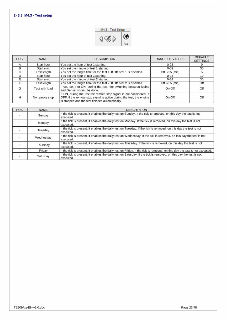
2- 6.3 M4.3 - Test setup
POS. NAME DESCRIPTION RANGE OF VALUES DEFAULT SETTINGS
A Start hour You set the hour of test 1 starting. 0-23 9 B Start min. You set the minute of test 1 starting. 0-59 30 C Test length You set the length time for the test 1. If Off, test 1 is disabled. Off -255 [min] 5 D Start hour You set the hour of test 2 starting. 0-23 10 E Start min. You set the minute of test 2 starting. 0-59 30 F Test length You set the length time for the test 2. If Off, test 2 is disabled. Off -255 [min] Off
G Test with load If you set it to ON, during the test, the switching between Mains and Genset should be done.
On-Off Off
H No remote stop If ON, during the test the remote stop signal is not considered. If OFF, if the remote stop signal is active during the test, the engine is stopped and the test finishes automatically.
On-Off Off
POS. NAME DESCRIPTION
- Sunday If the tick is present, it enables the daily test on Sunday. If the tick is removed, on this day the test is not executed.
- Monday If the tick is present, it enables the daily test on Monday. If the tick is removed, on this day the test is not executed.
- Tuesday If the tick is present, it enables the daily test on Tuesday. If the tick is removed, on this day the test is not executed.
- Wednesday If the tick is present, it enables the daily test on Wednesday. If the tick is removed, on this day the test is not executed.
- Thursday If the tick is present, it enables the daily test on Thursday. If the tick is removed, on this day the test is not executed.
- Friday If the tick is present, it enables the daily test on Friday. If the tick is removed, on this day the test is not executed.
- Saturday If the tick is present, it enables the daily test on Saturday. If the tick is removed, on this day the test is not executed.

TE809Ats-EN-v2.0.doc Page 24/48
2- 6.4 M4.4 - Security setup
The security setup menu permits to enter the access codes the permit to lock/unlock the programmation menus. By default, the access codes are set correctly, so you can access to all the menus. You have the possibility to protect the programmation menus entering wrong codes: this way the menus correspondent to the wrong code inserted are locked. When you want to unlock the menus, simply enter in this menu and set the codes to the correct values. The 6 codes are shown in the table. POS. NAME DESCRIPTION CODE
A Global code This is the password to access to the programmation menus. It’s possible to change it, from 000 to 999.
1
B Clear events log Confirm to erase events log register. - C State password Password to lock/unlock all the alarms except the mains, generator and engine ones. 70
D Mains password Enter the password that locks/unlocks the mains setup and the relative alarms. If you enter the code correctly to 60, the mains menu is completely unlocked. If you enter a wrong code, the menu is locked until the correct code will be inserted.
60
E Genset password Enter the password that locks/unlocks the alternator setup and the relative alarms. If you enter the code correctly to 50, the alternator setup is completely unlocked. If you enter a wrong code, the menu is locked.
50
F Engine password Enter the password that locks/unlocks the engine setup and the relative alarms. If you enter the code correctly to 40, the engine setup is completely unlocked. If you enter a wrong code, the menu is locked.
40
G Special password Enter the password that locks/unlocks the special functions setup. If you enter the code correctly to 30, the special functions setup is completely unlocked. If you enter a wrong code, the menu is locked.
30
H Connectivity password Enter the password that locks/unlocks the connectivity setup. If you enter the code correctly to 20, the connectivity setup is completely unlocked. If you enter a wrong code, the menu is locked.
20
I I/O password Enter the password that locks/unlocks the I/O setup. If you enter the code correctly to 10, the I/O setup is completely unlocked. If you enter a wrong code, the menu is locked.
10

TE809Ats-EN-v2.0.doc Page 25/48
2- 7 M5 - Alarms list
The alarms setup is composed by 4 different alarm groups:
a) Mains alarms b) Generator alarms c) Engine alarms d) General alarms
Select the category with the down and up arrows, then press “i” to confirm and enter. You will see a general screen for the setup of the alarms, composed by 4 pages. In the first page, select and confirm the parameter “a” to choose the code of the alarm. In the upper part of the screen you will see the name of the correspondent alarm. Then modify the parameters from “d” to “l” as you prefer. Return then to the first page and confirm the parameter “c” to save the modifications. For every alarm, you can program all the following parameters: POS. NAME DESCRIPTION RANGE
A Alarm code Select this parameter to choose the alarm that you want to set. All the parameters in the next pages refer to the alarm selected in this parameter. In the upper part of the screen you will see also the name correspondent to the code that you are selecting.
-
B Category of the alarm Name of the category selected from the first screen of the alarm setup. It’s not possible to modify it directly in this page. -
C Save alarm Parameter that has to be confirmed with the “i” button to save all the parameters from D to L in the configuration of the alarm selected at parameter A.
-
D Activation It permits to choose when the alarm condition must be verified and make the alarm appear: Always (always enabled), Run (active only with engine running) or Disabled (disabled).
Always - Run- Disabled
E Delay Before the activation of the alarm, the cause must remain present for this time. 0-255 [s]
F Retentive Choose if the alarm must be retentive (ON: the alarm indication remains on display until you press the reset button, even if the cause has disappeared) or not (OFF: the alarm indications disappears when the cause disappears).
Off-On
G Action Select the action in consequence of the activation of the alarm: Warning (only indication), Stop (the alarm stops the engine immediately) or Cooling (the alarms stops the engine with cooling).
Warning - Stop - Cooling
H Siren Set if the activation of the alarms must also activate the output programmed for Siren. It can be set to ON (the output set for “siren” is activated when the alarm is present) or OFF.
Off-On
I Remote
Set if the activation of the alarm must also send an SMS message if Remote APP option is enabled and one or more of programmed GMS numbers are correctly saved (see menu M7). It can be set to ON (if a modem is connected, the board sends a SMS when the alarm appears) or OFF. Enable also the single alarm flag inside modbus map.
Off-On
J Global 1 Set if the activation of the alarms must also activate the output programmed for Global alarm 1. It can be set to ON (the output is activated when the alarm is present) or OFF. Off-On
K Global 2 Set if the activation of the alarms must also activate the output programmed for Global alarm 2. It can be set to ON (the output is activated when the alarm is present) or OFF.
Off-On
L Global 3 Set if the activation of the alarms must also activate the output programmed for Global alarm 3. It can be set to ON (the output is activated when the alarm is present) or OFF. Off-On

TE809Ats-EN-v2.0.doc Page 26/48
2- 7.1 M5 - Alarms default parameters
Activation Action
N. Category Alarm code Alarm name
Alw
ays
Dis
able
d
Run
Del
ay
Ret
entiv
e
Coo
ling
Sto
p
War
ning
Sire
n
RE
MO
TE
Glo
bal 1
Glo
bal 2
Glo
bal 3
1 Mains 1208 Mains: low freq. � 2 � � 2 Mains 1209 Mains: high freq. � 2 � � 3 Mains 1213 Mains: V asymmetry � 1 � � � � 4 Mains 20025 Faulty mains � 2 � � 5 Mains 20034 KR feedback � 5 � � � � 6 Mains 20052 Mains: phase seq. � 0 � � � � 7 Mains 20060 Mains: low voltage � 5 � � 8 Mains 20061 Mains: high voltage � 5 � �
9 Generator 1201 GE: low freq. � 5 � � � � � 10 Generator 1202 GE: high freq. � 5 � � � � � 11 Generator 1205 GE: phase seq. � 0 � � � � � 12 Generator 1206 GE: short circuit � 2 � � � � � 13 Generator 1207 GE: Imax overload � 5 � � � � � 14 Generator 1214 GE: V asymmetry � 1 � � � � � 15 Generator 20007 Ground protection � 2 � � � � � 16 Generator 20032 Emergency stop � 0 � � � � � 17 Generator 20033 KG feedback � 5 � � � � � 18 Generator 20036 User alarm 1 � 3 � � � � � 19 Generator 20037 User alarm 2 � 3 � � � � � 20 Generator 20038 User alarm 3 � 3 � � � � � 21 Generator 20062 GE: low voltage � 5 � � � � � 22 Generator 20063 GE: high voltage � 5 � � � � � 23 Generator 20064 Electrical trip � 2 � � � � 24 Generator 20065 Load breaker open � 1 � � �
25 Generator 20066 GE protection � 2 � � � �
26 Engine 20015 Stop engine failure � 1 � � � � 27 Engine 20058 Start failure � 10 � � � � � 28 Engine 20067 Master com error � 10 � � � �
29 Engine 20068 Temperature alarm � 0 � � � � 30 Engine 20069 Oil alarm � 0 � � � � 31 Engine 20070 Battery alarm � 0 � � � � 32 Engine 20071 Fuel alarm � 0 � � � � 33 Engine 20072 Service alarm � 0 � � � � 34 Engine 20073 TE809G warning � 0 � � � � 35 Engine 20074 TE809G failure � 0 � � � �
36 General 20008 Test active � 0 � 37 General 20021 Remote start � 1 � 38 General 20022 Remote stop � 1 � � � 39 General 20026 EJP � 0 �
40 General 20027 Failed test � 0 � � � � �
41 General 20045 GE running… � 0 �
42 General 20046 GE ready… � 0 �
43 General 20059 TPS mode on � 0 �

TE809Ats-EN-v2.0.doc Page 27/48
2- 7.2 M5 - Alarms description
N. Alarm code
Alarm name Alarm description Menu / Parameter
1 1208 Mains: low freq. Indicates that the mains frequency is under the programmed threshold M1-F 2 1209 Mains: high freq. Indicates that the mains frequency is over the programmed threshold M1-E 3 1213 Mains: V asymmetry Indicates that the difference between the higher and the lower mains voltages is too high M1.K 4 20025 Faulty mains Indicates that the mains is out of limits M1-BCEF 5 20034 KR feedback If KR contactor output status is not equal to input status M8 6 20052 Mains: phase seq. Indicates a wrong phase sequence of the mains M1-J 7 20060 Mains: low voltage Indicates that the mains voltage is under the programmed threshold M1-C 8 20061 Mains: high voltage Indicates that the mains voltage is over the programmed threshold M1-B
9 1201 GE: low freq. Frequency values are under the programmed limits M2-F 10 1202 GE: high freq. Frequency values are over the programmed limits M2-E 11 1205 GE: phase seq. Indicates wrong generator voltages sequence M2-O 12 1206 GE: short circuit Indicates an instantaneous current higher than the programmed limits for short circuit M2-I 13 1207 GE: Imax overload Indicates an instantaneous current higher than the programmed limits for overload M2-H 14 1214 GE: V asymmetry Indicates that the difference between the higher and the lower genset voltages is too high M2-P 15 20007 Ground protection Ground protection digital input alarm M8 16 20032 Emergency stop It indicates that the input programmed as “emergency button” is active M8 17 20033 KG feedback If KG contactor output status is not equal to input status M8 18 20036 User alarm 1 Alarm that is present when the digital input programmed as user alarm 1 is active M8 19 20037 User alarm 2 Alarm that is present when the digital input programmed as user alarm 2 is active M8 20 20038 User alarm 3 Alarm that is present when the digital input programmed as user alarm 3 is active M8 21 20062 GE: low voltage Voltage values are under the programmed limits M2-C 22 20063 GE: high voltage Voltage values are over the programmed limits M2-B 23 20064 Electrical trip Alarm that indicates that the relative digital input is active M8 24 20065 Load breaker open Alarm that indicates that the relative digital input is active M8 25 20066 GE protection Alarm that indicates that the relative digital input is active M8
26 20015 Stop engine failure Indicates that the engine is detected running if the remote start output is removed and after cooling time delay + 10s. M3.1
27 20058 / 1001
Start failure Indicates that the engine is not detected running after the start attempts in automatic mode M3.1
28 20067 Master com error Indicates a communication error with the TE809G connected - 29 20068 Temperature alarm Indicates a temperature alarm from the TE809G controller - 30 20069 Oil alarm Indicates an oil alarm from the TE809G controller - 31 20070 Battery alarm Indicates a battery alarm from the TE809G controller - 32 20071 Fuel alarm Indicates a fuel alarm from the TE809G controller - 33 20072 Service alarm Indicates a service alarm from the TE809G controller - 34 20073 TE809G warning Indicates a warning message from the TE809G controller - 35 20074 TE809G failure Indicates a severe alarm message from the TE809G controller -
36 20008 Test active Signalization active during test procedure M4.3 37 20021 Remote start Indicates remote start function from digital input M8 38 20022 Remote stop Indicates remote stop function from digital input M8 39 20026 EJP Indicates that the remote start input (if programmed as EJP) is active M6.1
40 20027 Failed test Indicates an unsuccessful test in automatic mode: a stopping alarm occurs during test procedure
M4.3
41 20045 GE running… Indication that is active when the generator is detected running - 42 20046 GE ready… Indication that the generator is not running and without blocking alarms - 43 20059 TPS mode on Indicates that the TPS (timed programmable start) is active M6.4

TE809Ats-EN-v2.0.doc Page 28/48
2- 8 M6 - Special functions
The TE809 has 5 menus for special functions: EJP, Start by mains kW, Dummy load, TPS, Hour counters. The relative parameters can be set in this menu. The submenus are the following:
A) EJP - only auto mode B) Start by mains kW (peak shaving) - only auto mode C) Dummy Load - only auto mode D) TPS (timer programmable start stop) - only auto mode E) Hour counters
2- 8.1 M6.1 - EJP
Start the generator by a remote signal on one of the programmable inputs previously programmed as remote start (see par. 2-10). When that input is closed to negative, after a delay time, the generator starts. Then:
a) If EJP 2 ENABLE is OFF: when the KG DELAY time has elapsed, TE809 switches the changeover switch on generator side, even if the mains is detected.
b) If EJP 2 ENABLE is ON: after the generator has started, you have to wait that the second programmable input (that you have to set to CHANGEOVER, see par. 2-10) is closed to negative, then after the KG delay time, TE809 switches the changeover switch on generator side, even if the mains is detected.
“No KR with EJP” option permits to inhibit, in case of generator alarm, the changeover switch on mains side.
POS. NAME DESCRIPTION RANGE OF
VALUES DEFAULT SETTINGS
A EJP enable If ON the function is enabled, if OFF the function is disabled. On-Off Off
B Start delay It is the delay time that elapses when you close to negative the terminal programmed as remote start before the generator starting. 0-999 [s] 5
C KG delay
It is the delay time that elapses after the starting of the generator (if parameter D is OFF) or after the closure to negative of the input programmed as changeover (if parameter D is ON) before the switching of the changeover switch.
0-999 [s] 5
D EJP2 input
If ON, it enables the changeover switch control by the changeover input terminal closed to negative; when closed and after the delay time at point C, the load switches to generator. If OFF, the changeover input is not necessary to control the changeover switch: changeover switch is automatically closed on generator side when the engine is started by the remote start input and after the delay time at point C.
On-Off Off
E No KR with EJP If ON, when EJP mode is active (remote start input active), the mains contactor opens and it’s not possible to close it also if the generator is stopped by an alarm.
On-Off Off
F Off delay It is the delay time during which the EJP signal must be disabled to permit the stopping of the generator and the switching on the mains.
0-999 [s] 5

TE809Ats-EN-v2.0.doc Page 29/48
2- 8.2 M6.2 - Start by mains kW
Function that allows the generator’s automatic start and stop, according to the maximum and minimum thresholds programmable on mains consumption. If the load consumption from the mains supplies exceeds the START THRESHOLD for a period of time longer then the TIME FOR START, TE809 starts the generator and switch the load for the generator. When the value of load’s consumption is less than the STOP THRESHOLD at least for the TIME FOR STOP time, the load is commutated to the mains (if available) and the generator is stopped. If the mains is missing, the load remains on generator until the mains voltage is detected.
POS. NAME DESCRIPTION RANGE OF
VALUES DEFAULT SETTINGS
A kW mains Enable If ON the function is enabled, if OFF it is disabled. On-Off Off
B Start power Load supplied by the mains: if the power consumption exceeds this value (at least for the “time for start" at point C), the generator starts and the power switching moves on the generator.
0-255 [%] 80
C Time for start It is the delay time for which the load consumption must remain over the threshold value on the mains (point B); after this time the generator starts.
0-255 [s] 5
D Stop power
Load is supplied by the generator: if the power consumption returns to be less than this threshold value set (at least for the “time for stop at point E), the load switches to the Mains and the generator is stopped.
0-255 [%] 30
E Time for stop It’s the delay time for which the load consumption must remain below the threshold value; after this time the load returns to the Mains and the generator is stopped. 0-255 [s] 5
Note: power percentage thresholds are referred to the rated kW value, that is calculated from the rated voltage, the rated current, the rated power factor (0,8) and the type of the system selected.
2- 8.3 M6.3 - Dummy load
Function that allows to activate one of the programmable outputs, according to the maximum and minimum thresholds programmable on load consumption. If the load consumption is lower than the DUMMY ON for a period of time longer then the ON DELAY, the board activates all the outputs that you programmed for Dummy load function (see par. 2-10 for the programmation of the outputs). When the value of load consumption is higher than the DUMMY OFF at least for the OFF DELAY time, the outputs are de-activated. To activate this function, you have to set at least one of the programmable outputs for “dummy load” (see par. 2-10), then you have to set the following parameters.
POS. NAME DESCRIPTION RANGE OF
VALUES DEFAULT SETTINGS
A Dummy enable If ON the function is enabled, if OFF the function is disabled. On / Off Off
B Dummy On Load supplied by generator: if the power consumption is lower than this value (at least for the “On delay" at point C), the outputs programmed as “dummy load” are activated.
0-255 [%] 30
C On delay It is the delay time for which the load consumption must remain under the threshold value on the generator (point B); after this time the outputs are activated.
0-255 [s] 5
D Dummy Off Load is supplied by the generator: if the power consumption exceeds the threshold value set (at least for the “Off delay” at point E), the outputs programmed as “dummy load” are deactivated.
0-255 [%] 80
E Off delay It is the delay time for which the load consumption must remain over the threshold value on the generator (point D); after this time the outputs are deactivated.
0-255 [s] 5
Note: power percentage thresholds are referred to the rated kW value, that is calculated from the rated voltage, the rated current, the rated power factor (0,8) and the type of the system selected.

TE809Ats-EN-v2.0.doc Page 30/48
2- 8.4 M6.4 - TPS
This function similar to automatic test is used to program up to two working intervals which activate the generator at chosen clock time and stop it at a chosen clock time. It's also possible to program if the working time is with or without load, with or without remote stop and which are the days allowed to work.
POS. NAME DESCRIPTION RANGE OF
VALUES DEFAULT SETTINGS
A 1-2 TPS1 start (h) - TPS1 start (m) TPS1 start hour and minute. 0-23 / 0-59 8:30
B 1-2 TPS1 stop (h) - TPS1 stop (m)
TPS1 stop hour and minute. 0-23 / 0-59 12:30
C TPS1 enable If Off, the working period 1 is disabled. On-Off Off
D TPS2 start (h) - TPS2 start (m) TPS2 start hour and minute. 0-23 / 0-59 14:30
E TPS2 stop (h) - TPS2 stop (m)
TPS2 stop hour and minute. 0-23 / 0-59 18:30
F TPS2 enable If Off, the working period 2 is disabled. On-Off Off
G TPS with load If On, the TPS mode will be with load on generator side, id Off the load will remain on mains side and the changeover will happen only in case of mains failure during TPS.
On-Off Off
H No remote stop If On, the TPS mode will override remote stop activation to start the generator. On-Off Off
POS. NAME DESCRIPTION - Sunday If the tick is present, it enables the TPS on Sunday. If the tick is removed, on this day the TPS is not executed. - Monday If the tick is present, it enables the TPS on Monday. If the tick is removed, on this day the TPS is not executed. - Tuesday If the tick is present, it enables the TPS on Tuesday. If the tick is removed, on this day the TPS is not executed.
- Wednesday If the tick is present, it enables the TPS on Wednesday. If the tick is removed, on this day the TPS is not executed.
- Thursday If the tick is present, it enables the TPS on Thursday. If the tick is removed, on this day the TPS is not executed. - Friday If the tick is present, it enables the TPS on Friday. If the tick is removed, on this day the TPS is not executed. - Saturday If the tick is present, it enables the TPS on Saturday. If the tick is removed, on this day the TPS is not executed.
2- 8.5 M6.5 - Hours
POS. NAME DESCRIPTION RANGE OF VALUES
DEFAULT SETTINGS
A Initial work Here you can set a value of the work hours, then confirm the parameter D to set the actual work hours to this value.
0-999999 [h] 0
B KG hours Here you can set a value of the work hours with KG closed, then confirm the parameter D to set the actual work hours with KG closed to this value.
0-999999 [h] 0
C KR hours Here you can set a value of the hours with KR closed, then confirm the parameter D to set the actual hours with KR closed to this value.
0-999999 [h] 0
D Counter reset Confirm this parameter to set the values at parameters A, B and C. It becomes 1 for a small time after you confirmed it, to indicate that the procedure of hours updating is working.
0-1 0
E Clear events log If you confirm this option with "i" button, the events in the events log are deleted.
- Ok
TE809Ats-EN-v2.0.doc Page 31/48
2- 9 M7 - Connectivity
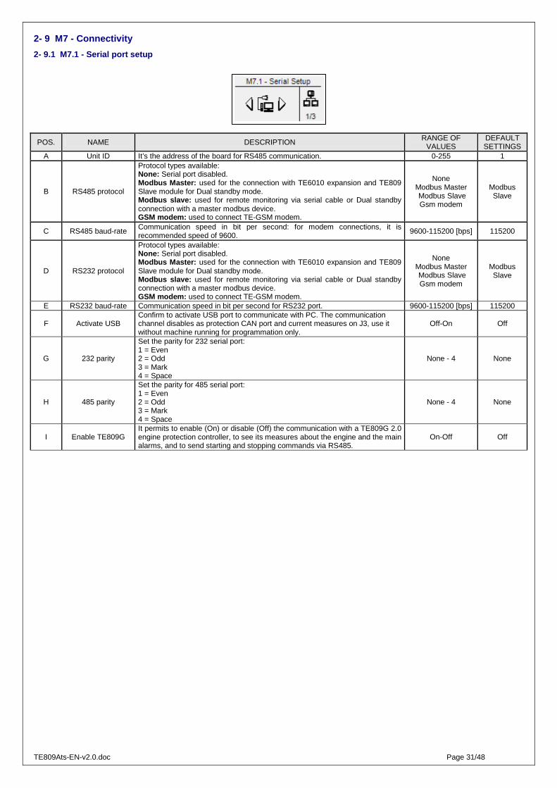
2- 9.1 M7.1 - Serial port setup
POS. NAME DESCRIPTION RANGE OF VALUES
DEFAULT SETTINGS
A Unit ID It’s the address of the board for RS485 communication. 0-255 1
B RS485 protocol
Protocol types available: None: Serial port disabled. Modbus Master: used for the connection with TE6010 expansion and TE809 Slave module for Dual standby mode. Modbus slave: used for remote monitoring via serial cable or Dual standby connection with a master modbus device. GSM modem: used to connect TE-GSM modem.
None Modbus Master Modbus Slave Gsm modem
Modbus Slave
C RS485 baud-rate Communication speed in bit per second: for modem connections, it is recommended speed of 9600.
9600-115200 [bps] 115200
D RS232 protocol
Protocol types available: None: Serial port disabled. Modbus Master: used for the connection with TE6010 expansion and TE809 Slave module for Dual standby mode. Modbus slave: used for remote monitoring via serial cable or Dual standby connection with a master modbus device. GSM modem: used to connect TE-GSM modem.
None Modbus Master Modbus Slave Gsm modem
Modbus Slave
E RS232 baud-rate Communication speed in bit per second for RS232 port. 9600-115200 [bps] 115200
F Activate USB Confirm to activate USB port to communicate with PC. The communication channel disables as protection CAN port and current measures on J3, use it without machine running for programmation only.
Off-On Off
G 232 parity
Set the parity for 232 serial port: 1 = Even 2 = Odd 3 = Mark 4 = Space
None - 4 None
H 485 parity
Set the parity for 485 serial port: 1 = Even 2 = Odd 3 = Mark 4 = Space
None - 4 None
I Enable TE809G It permits to enable (On) or disable (Off) the communication with a TE809G 2.0 engine protection controller, to see its measures about the engine and the main alarms, and to send starting and stopping commands via RS485.
On-Off Off

TE809Ats-EN-v2.0.doc Page 32/48
2- 9.2 M7.2 - GSM Setup
POS. NAME DESCRIPTION RANGE OF VALUES
DEFAULT SETTINGS
A Modem status Status of the modem: initial (initializing phase), wait (waiting), ready (stand-by phase), send (sending a message), send wait (waiting the response). - -
B APP enable It enables the automatic status messages and alarm via SMS for SMS app or standard mobile.
On-Off Off
C SMS filter (s) Set the minimum time between two different SMS events to avoid to send many messages in short period of time.
1-255 [s] 3
D 1-2 Generator Ok - Engine running
If enabled, the activation of this condition will trigger a SMS info message On-Off Off-On
E 1-2 Engine stopping - Stopping ok
If enabled, the activation of this condition will trigger a SMS info message On-Off Off-On
F 1-2 KG active - KR active
If enabled, the activation of this condition will trigger a SMS info message On-Off On-On
G 1-2 Auto mode - Test mode
If enabled, the activation of this condition will trigger a SMS info message On-Off On-Off
H 1-2 Off mode - Man mode
If enabled, the activation of this condition will trigger a SMS info message On-Off On-On
I 1-2 Ejp on - Mains return
If enabled, the activation of this condition will trigger a SMS info message On-Off Off-Off
J Remote stop If enabled, the activation of this condition will trigger a SMS info message On-Off On
K 1-2-3 Pw char 1-2-3
Set the 6 characters password code for SMS commands: if password is different from 0-0-0-0-0-0, every SMS command received without the correct password code will be discarded. The syntax to send the correct SMS with password is: PWD=[XXXXXX] [Command] For example if password is 1-0-2-A-z-X, the SMS command to start the engine must be composed this way: PWD=102AzX START
[0-9] or
[A-Z] or
[a-z]
0 - 0 - 0
L 1-2-3 Pw char 4-5-6 Set the other 3 characters for the password
[0-9] or
[A-Z] or
[a-z]
0 - 0 - 0
M Call Numbers It shows the mobile phone numbers set in position 1 - - N Call Numbers It shows the mobile phone numbers set in position 2 - - O Call Numbers It shows the mobile phone numbers set in position 3 - - P Call Numbers It shows the mobile phone numbers set in position 4 - - Q Call Numbers It shows the mobile phone numbers set in position 5 - -
2- 9.2.1 - System info SMS message
SMS sent by remote device will be received by mobile device with the following format:
EAS=Gen.Name-------- O=AUTO,P=000 M237,237,232,49.9 G000,000,000,00.0 A003.0,000.0,000.0 B=14.1V,h=00000 T=99%,U=00 MC=ON,Z=00 E0000,A000 #41001,Start failure

TE809Ats-EN-v2.0.doc Page 33/48
SMS SECTION FORMAT DESCRIPION # DATA CHARACTERS DATA DESCRIPTION
EAS [Message type] 3 Message header for TE809 2.0 =---------------- =[Generator name] 16 Name of the generator
O=AUTO O=[Program] 4 Operative mode active (“OFF“-“MAN“-“AUTO”-“TEST”) ,P=000 ,P=[Active power kW] 3 Total active power M237 M[Mains voltage line 1] 3 Mains L1-n voltage ,237 ,[Mains voltage line 2] 3 Mains L2-n voltage ,232 ,[Mains voltage line 3] 3 Mains L3-n voltage ,49.9 ,[Mains frequency] 4 Mains frequency
G=000 G=[Genset voltage line 1] 3 Generator L1-n voltage ,000 ,[Genset voltage line 2] 3 Generator L2-n voltage ,000 ,[Genset voltage line 3] 3 Generator L3-n voltage ,00.0 ,[Genset frequency] 4 Generator frequency
A003.0 A[Load current line 1] 4 Load current L1 ,000,0 ,[Load current line 2] 4 Load current L2 ,000.0 ,[Load current line 3] 4 Load current L3
B=14.1V B=[Battery voltage]V 4 Battery voltage ,h=00000 ,h=[Work hours] 5 Total work hours T=99% T=[Fuel level] 2 Fuel level percentage (if connected to a TE809G controller) %,U=00 %,U=[Oil pressure] 2 Oil pressure (if connected to a TE809G controller)
MC=ON [Contactor status] 5
Contactors status: • MC=ON means mains contactor ON • GC=ON means generator contactor ON • C=OFF means both contactors OFF
,Z=00 ,Z=[Engine temperature] 3 Engine temperature (if connected to a TE809G controller) E0 E[Input I4.4 status] 1 Status of input I4.4 (0=not active, 1=active) 0 [Input I4.5 status] 1 Status of input I4.5 (0=not active, 1=active) 0 [Input I4.6 status] 1 Status of input I4.6 (0=not active, 1=active) 0 [Input I4.7 status] 1 Status of input I4.7 (0=not active, 1=active)
,A0 ,A[output O5.8 status] 1 Status of output 5.8 (0=not active, 1=active) 0 [output O5.9 status] 1 Status of output 5.9 (0=not active, 1=active) 0 [output O5.10 status] 1 Status of output 5.10 (0=not active, 1=active)
#41001 #[message ID] 5
Message ID without alarms: • 00250 = Power on • 00201 = Generator ready • 00202 = Engine running • 00203 = Engine stopping • 00204 = Engine stop successful • 00205 = KG on • 00206 = KR on • 00207 = Auto mode • 00208 = Test mode • 00209 = Off mode • 00210 = Man mode • 00211 = Ejp on • 00212 = Mains return • 00219 = Remote stop • 00222 = System info
Message ID with alarms, the first digit is the alarm severity:
• 1 = Global alarm #1 On • 2 = Global alarm #2 On • 3 = Global alarm #3 On • 4 = Shutdown alarm
The other four digits are the alarm code, if the alarm code is greater than 20000, than the SMS code will be:
[SMS_alarm_code]=[Alarm_ID]-17000
For example "Emergency stop" alarm code 20032 which is a shutdown alarm will be reported with the following code:
[Emergency_stop_alarm_code] = (4*10^5)+(20032-17000) = 43032
,Start failure ,[message text] 16 Message text

TE809Ats-EN-v2.0.doc Page 34/48
2- 9.2.2 - SMS commands list
This is the list of commands which could be sent to mobile device:
COMMAND NAME TEXT SENT (case sensitive) DESCRIPTION
MANUAL MODE MAN Activate manual mode on remote device AUTO MODE AUT Activate auto mode on remote device OFF MODE OFF Activate Off mode on remote device
RESET ALARMS RESET Alarms reset on remote device MAINS CONTACTOR MAINS Changeover switch on mains side in manual mode
GENSET CONTACTOR GEN Changeover switch on generator side in manual mode
START ENGINE START Start generator command in manual mode (if man mode is not selected, the controller will activate manual mode before start)
STOP ENGINE STOP Stop generator command in manual mode (if man mode is not selected, the controller will activate manual mode before start)
TEST MODE TEST Activate test mode
NAME NAME:[name_parameter]
Name_paramete is max 16 characters string
Set remote device name
CUSTOM PARAMETER
SET:[ID_parameter] [Value_parameter]
Both values are numeric between 0-9999; for example if I
want to set parameter 300 to 10, the text sent will be:
SET:300 10
Set an enabled parameter of remote device. Warning: consult the correct memory map to verify the address of the parameter you want to modify. A wrong setting could compromise the functioning of the machine.
SET GSM NUMBER
SET[Position_number]:[Cellphone_number]
Position_number value is numeric between 1-6,
cellphone_number is a telephone number which allows the remote device to know where SMS need to be sent.
For instance to set number 339 333 9000 in position #3 of
remote device, the sent text will be:
SET3:3393339000
Set the telephone number which will be used by remote device to send SMS. Usually this number is the one of the receiver device where the app is installed.
SYSTEM INFO INFO Command to request info to the remote device.
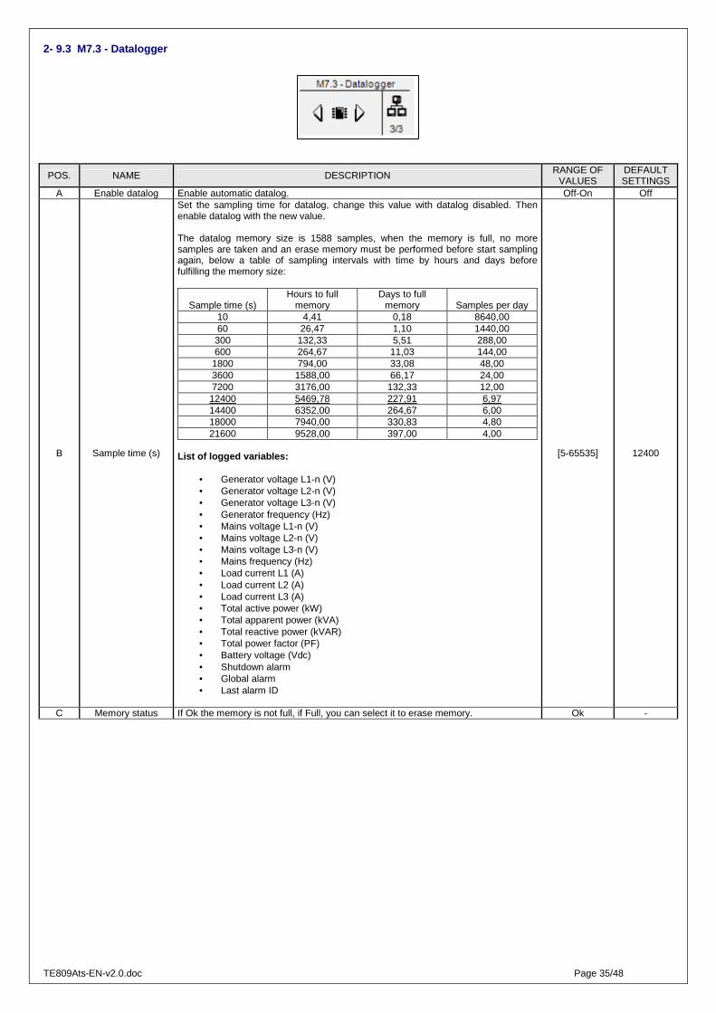
TE809Ats-EN-v2.0.doc Page 35/48
2- 9.3 M7.3 - Datalogger
POS. NAME DESCRIPTION RANGE OF VALUES
DEFAULT SETTINGS
A Enable datalog Enable automatic datalog. Off-On Off
B Sample time (s)
Set the sampling time for datalog, change this value with datalog disabled. Then enable datalog with the new value. The datalog memory size is 1588 samples, when the memory is full, no more samples are taken and an erase memory must be performed before start sampling again, below a table of sampling intervals with time by hours and days before fulfilling the memory size:
Sample time (s) Hours to full
memory Days to full
memory Samples per day 10 4,41 0,18 8640,00 60 26,47 1,10 1440,00 300 132,33 5,51 288,00 600 264,67 11,03 144,00
1800 794,00 33,08 48,00 3600 1588,00 66,17 24,00 7200 3176,00 132,33 12,00 12400 5469,78 227,91 6,97 14400 6352,00 264,67 6,00 18000 7940,00 330,83 4,80 21600 9528,00 397,00 4,00
List of logged variables:
• Generator voltage L1-n (V) • Generator voltage L2-n (V) • Generator voltage L3-n (V) • Generator frequency (Hz) • Mains voltage L1-n (V) • Mains voltage L2-n (V) • Mains voltage L3-n (V) • Mains frequency (Hz) • Load current L1 (A) • Load current L2 (A) • Load current L3 (A) • Total active power (kW) • Total apparent power (kVA) • Total reactive power (kVAR) • Total power factor (PF) • Battery voltage (Vdc) • Shutdown alarm • Global alarm • Last alarm ID
[5-65535] 12400
C Memory status If Ok the memory is not full, if Full, you can select it to erase memory. Ok -

TE809Ats-EN-v2.0.doc Page 36/48
2- 10 M8 - IO setup
The IO setup is composed by 6 submenus: A) Input setup: Submenu that contains all the parameters about the input functions available. B) Output setup: Submenu that contains all the parameters about the output functions available. C) Input type: Submenu to set input types, you can select between disabled, normally open, normally closed or analog if the input allows it. D) Output type: Submenu to set output types, you can select between disabled, normally open or normally closed E) Calibrations: Submenu to adjust voltage and current measures with a programmable offset. F) Expansion: Submenu to configure expansion outputs
2- 10.1 M8.1 - Input setup
The I/O menu permits to select the type of use of the programmable digital inputs. The inputs I4.4, I4.5, I4.6, I4.7, I4.8, and the digital inputs from the TE6010 expansion board (EXIN0 - EXIN7), can be programmed as:
POS. NAME DESCRIPTION RANGE OF VALUES DEFAULT SETTINGS
A Changeover Changeover command from digital contact: works in auto mode with remote start, EJP, automatic test. If it's activated with generator measures within limits, the load is switched to genset.
None - I4.4 - I4.5 - I4.6 - I4.7 - I4.8 - ExIn_0 ~ ExIn_7
None
B Remote start Start the generator in auto mode with mains detected within limits. Same as parameter A I4.6
C Remote stop Stop the generator in auto mode even if there are some conditions which would start the engine, as faulty mains or remote start. It's possible to disable remote stop during normal test or TPS test.
Same as parameter A I4.7
D Ground protection Ground protection alarm from digital contact. Same as parameter A I4.5
E Feedback KG Feedback generator contactor. Is activated if KG output is On but feedback is not and viceversa.
Same as parameter A None
F Feedback KR
Feedback generator contactor. Is activated if KR output is On but feedback is not and viceversa. Please note: This alarm is considered to start the generator in auto mode with "Start by KR" parameters programmed to On. In this case this alarm should be programmed as retentive to avoid start and stop loops.
Same as parameter A None
G User alarm 1 Label editable alarm from digital contact Same as parameter A None H User alarm 2 Label editable alarm from digital contact Same as parameter A None I User alarm 3 Label editable alarm from digital contact Same as parameter A None J Off mode Activates Off mode. Same as parameter A None K Auto mode Activates automatic mode. Same as parameter A None
L External mains control
If the selected input is active, the mains is detected within limits also if measurements of voltage and frequency are outside programmed values.
Same as parameter A None
M Electrical trip “Electrical trip” alarm from digital contact. Same as parameter A I4.4 N Load breaker open “Load breaker open” alarm from digital contact. Same as parameter A None O GE protection “GE protection” alarm from digital contact. Same as parameter A I4.8

TE809Ats-EN-v2.0.doc Page 37/48
2- 10.2 M8.2 - Output setup
The Output setup permits to select the type of use of the programmable outputs. The outputs O5.8, O5.9, O5.10, O5.11, O5.5 and O5.4 can be programmed as: • None: no function associated to the output • Start: the output is used to command the start of the genset to the engine protection controller • Siren: the output is used to command a siren that sounds when an alarm with siren enabled appears • Global alarm 1: the output is used to command an indication when an alarm set as general alarm 1 appears. The output remains active until you
reset or the alarm disappears • Engine running: the output is activated when the generator is running • Test active: the output is used to signal that the test is active • Dummy load: the output is used for the dummy load function. To have more information about this function, see menu 2-8.3 • Off mode: indicates that the controller is in off/reset mode • Auto mode: indicates that the controller is in automatic mode • Man mode: indicates that the controller is in manual mode • Global alarm 2: the output is used to command an indication when an alarm set as general alarm 2 appears. The output remains active until you
reset or the alarm disappears • Global alarm 3: the output is used to command an indication when an alarm set as general alarm 3 appears. The output remains active until you
reset or the alarm disappears • KG active: indicates that the generator contactor is closed • KR active: indicates that the mains contactor is closed • Alarm A: the output is active when the alarm assigned to A position by M8.2 - g parameter is active • Alarm B: the output is active when the alarm assigned to B position by M8.2 - h parameter is active • Alarm C: the output is active when the alarm assigned to C position by M8.2 - i parameter is active • Start failure: indicates that the generator is not detected running after the starting procedure • Electrical trip: the output is activated if the Electrical trip alarm is active • GE.ready: the output is activated when the generator is ready to take the load POS. NAME RANGE OF VALUES DEFAULT SETTINGS
A O5.8 None - Start - Siren - Global alarm 1 - Engine running - Test active - Dummy load - Off mode - Auto mode - Man mode - Global alarm 2 - Global alarm 3 - KG active - KR active - Alarm A - Alarm B - Alarm C - Start failure - Electrical trip – GE ready
Global alarm 1
B O5.9 Same as parameter A Auto mode C O5.10 Same as parameter A Man mode D O5.11 Same as parameter A Siren E O5.5 Same as parameter A Start failure F O5.4 Same as parameter A Start G Alarm A [Off - 64] - see single alarm ID list below Off H Alarm B [Off - 64] - see single alarm ID list below Off I Alarm C [Off - 64] - see single alarm ID list below Off

TE809Ats-EN-v2.0.doc Page 38/48
Single alarms ID list:
Use the list below in conjunction with M8.2G, M8.2H and M8.2 I parameters to assign a specific alarm to an output.
Configuration example:
• M8.2 - b programmed to "ALARM A"
• M8.2 - c programmed to "ALARM B"
• M8.2 - d programmed to "ALARM C"
• M8.2 - g programmed to 8
• M8.2 - h programmed to 4
• M8.2 - i programmed to 3
With this configuration output O5.9 will be activated with "Mains phase seq." alarm, output
O5.10 will be activated with "Mains: high voltage" and output 5.11 will be activated with
"Mains: low voltage" alarm.
1 Mains: low freq.
2 Mains: high freq
3 Mains: low voltage
4 Mains: high voltage
5 Mains: v asymmetry
6 Faulty mains
7 KR feedback
8 Mains phase seq.
9 Ge: low freq.
10 Ge: high freq.
11 Ge: low voltage
12 Ge: high voltage
13 Ge: phase seq.
14 Ge: short circuit
15 Ge: Imax
16 Ge: v asymmetry
17 Ground protection
18 Emergency stop
19 KG feedback
20 User alarm1
21 User alarm2
22 User alarm3
23 Start failure
24~32 NOT USED
33 Stop engine failure
34~45 NOT USED
46 Test fail
47~53 NOT USED
54 Electrical trip
55 Load breaker open
56 External GE failure
57 Master Com error
58 TE809G temp. alarm
59 TE809G oil alarm
60 TE809G battery alarm
61 TE809G fuel alarm
62 TE809G service alarm
63 TE809G warning alarm
64 TE809G shutdown alarm

TE809Ats-EN-v2.0.doc Page 39/48
2- 10.3 M8.3 - Input type
The input type setup permits to select the type of programmable inputs. The inputs I4.4, I4.5, I4.6, I4.7, I4.8 can be programmed as:
• Disabled: the input is not active • Digital NO: the input is digital type normally open • Digital NC: the input is digital type normally closed
POS. NAME RANGE OF VALUES DEFAULT SETTINGS A I4.4 Disabled – Digital NO – Digital NC Digital NO B I4.5 Disabled – Digital NO – Digital NC Digital NO C I4.6 Disabled – Digital NO – Digital NC Digital NO D I4.7 Disabled – Digital NO – Digital NC Digital NO E I4.8 Disabled – Digital NO – Digital NC Digital NO
2- 10.4 M8.4 - Output type
The output type setup permits to select the type of programmable outputs. The outputs O5.8, O5.9, O5.10, O5.11, O5.4, O5.5 can be programmed as:
• Disabled: the output is not active • Digital NO: the output is digital type normally open • Digital NC: the output is digital type normally closed
POS. NAME RANGE OF VALUES DEFAULT SETTINGS
A O5.8 Disabled – Digital NO – Digital NC Digital NO B O5.9 Disabled – Digital NO – Digital NC Digital NO C O5.10 Disabled – Digital NO – Digital NC Digital NO D O5.11 Disabled – Digital NO – Digital NC Digital NO E O5.4 Disabled – Digital NO – Digital NC Digital NO F O5.5 Disabled – Digital NO – Digital NC Digital NO
2- 10.5 M8.5 - Calibration
The measures setup allows to adjust the measured values for genset and mains voltages and load currents. For each voltage measure it’s possible to set a calibration offset with steps of 0.1 V. For each current measure the offset is a percentage of the CT ratio, in steps of 0,1 %.
POS. NAME RANGE OF VALUES DEFAULT SETTINGS A VL1 Gen -100 +100 (V/10) 0 B VL2 Gen -100 +100 (V/10) 0 C VL3 Gen -100 +100 (V/10) 0 D VL1 Mains -100 +100 (V/10) 0 E VL2 Mains -100 +100 (V/10) 0 F VL3 Mains -100 +100 (V/10) 0 G IL1 50.0 – 150.0 (%) 100 H IL2 50.0 – 150.0 (%) 100 I IL3 50.0 – 150.0 (%) 100

TE809Ats-EN-v2.0.doc Page 40/48
2- 10.6 M8.6 - Expansion
The Expansion setup permits to select the type of use of the programmable outputs of an eventual TE6010 expansion board. The outputs from ExOut_1 to ExOut_7 can be programmed as: • None: no function associated to the output • Start: the output is used to command the start of the genset to the engine protection controller • Siren: the output is used to command a siren that sounds when an alarm with siren enabled appears • Global alarm 1: the output is used to command an indication when an alarm set as general alarm 1 appears. The output remains active until you
reset or the alarm disappears • Engine running: the output is activated when the generator is running • Test active: the output is used to signal that the test is active • Dummy load: the output is used for the dummy load function. To have more information about this function, see menu 2-8.3 • Off mode: indicates that the controller is in off/reset mode • Auto mode: indicates that the controller is in automatic mode • Man mode: indicates that the controller is in manual mode • Global alarm 2: the output is used to command an indication when an alarm set as general alarm 2 appears. The output remains active until you
reset or the alarm disappears • Global alarm 3: the output is used to command an indication when an alarm set as general alarm 3 appears. The output remains active until you
reset or the alarm disappears • KG active: indicates that the generator contactor is closed • KR active: indicates that the mains contactor is closed • Alarm A: the output is active when the alarm assigned to A position by M8.2 - g parameter is active • Alarm B: the output is active when the alarm assigned to B position by M8.2 - h parameter is active • Alarm C: the output is active when the alarm assigned to C position by M8.2 - i parameter is active • Start failure: indicates that the generator is not detected running after the starting procedure • Electrical trip: the output is activated if the Electrical trip alarm is active • GE ready: the output is activated when the generator is ready to take the load All the parameters available in the Expansion setup are:
POS. NAME RANGE OF VALUES DEFAULT SETTINGS
A Enable On to enable communication between TE809 and expansion board. Off
B Bitrate (bps)
Change the serial speed value for expansion board. To activate the new port speed the expansion must be switch off. At the new startup the serial port will be ready at the new speed value: 1 = Set 9600 bps 2 = Set 19200 bps 3 = Set 38400 bps (expansion def.) 4 = Set 57600 bps 5 = Set 115200 bps
0 (expansion def.)
C Timeout (s) Set the timeout delay on communication between TE809A and expansion board: Set the value from 1 to 255 (s), 0 is the expansion default value which is 5 s.
0 (expansion def.)
D ExOut_0 None - Start - Siren - Global alarm 1 - Engine running - Test active - Dummy load - Off mode - Auto mode - Man mode - Global alarm 2 - Global alarm 3 - KG active - KR active - Alarm A - Alarm B - Alarm C - Start failure - Electrical trip – GE ready
None
E ExOut_1 Same as parameter A None F ExOut_2 Same as parameter A None G ExOut_3 Same as parameter A None H ExOut_4 Same as parameter A None I ExOut_5 Same as parameter A None J ExOut_6 Same as parameter A None K ExOut_7 Same as parameter A None
Note : If you are using a TE6010M (8 digital outputs), the 8 outputs are from ExOut_0 to ExOut_7. If you are using a TE6010C (5 relay outputs), the 5 outputs are from ExOut_0 to ExOut_4.

TE809Ats-EN-v2.0.doc Page 41/48
2- 10.7 Expansion board TE6010
The Expansion board TE6010 permits to increase the number of inputs/outputs of the TE809. It is composed by a base module (TE6010 base) and 1 or more input/output modules. By default, the TE809 can command 1 TE6010 with one of the following configurations:
a) 8 digital inputs (TE6010 base + TE6010B) b) 8 digital outputs (TE6010 base + TE6010M) c) 8 digital inputs + 8 digital outputs (TE6010 base + TE6010B + TE6010M) d) 5 relay outputs (TE6010 base + TE6010C)
It means that it’s possible to connect a TE6010 expansion board to an already working TE809 (from v1.1.4) without any update of the existing TE809. 2- 10.7.1 - 8 digital inputs
It’s used the expansion TE6010B, with 8 digital inputs NPN type. Every input has his own common. 1 TE6010 base with: Bank 1: Not used Bank 2: TE6010B Note: the TE6010B expansion can be connected only to bank 2 2- 10.7.2 - 8 digital outputs
It’s used the expansion TE6010M, with 8 digital outputs, NPN type. For every output the common is already connected to the battery positive. When the output is active the relative OUT terminal is connected to battery negative. 1 TE6010 base with: Bank 1: TE6010M Bank 2: Not used Note: the TE6010M expansion can be connected only to bank 1
DIP SWITCH ADDRESS RS485
CONNECTOR 4P4C
CONNECTOR 4P4C
ACTIVATION OF TERMINATION RESISTOR
SU
PP
LY
8 -
35 V
DC
SU
PP
LY
8 -
35 V
DC
DIP SWITCH ADDRESS RS485
CONNECTOR 4P4C
CONNECTOR 4P4C
ACTIVATION OF TERMINATION RESISTOR
SU
PP
LY
8 -
35 V
DC
SU
PP
LY
8 -
35 V
DC
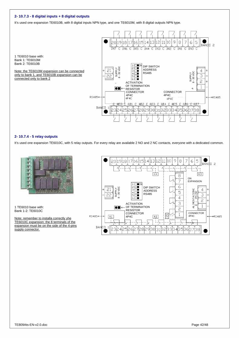
TE809Ats-EN-v2.0.doc Page 42/48
2- 10.7.3 - 8 digital inputs + 8 digital outputs
It’s used one expansion TE6010B, with 8 digital inputs NPN type, and one TE6010M, with 8 digital outputs NPN type. 1 TE6010 base with: Bank 1: TE6010M Bank 2: TE6010B Note: the TE6010M expansion can be connected only to bank 1, and TE6010B expansion can be connected only to bank 2 2- 10.7.4 - 5 relay outputs
It’s used one expansion TE6010C, with 5 relay outputs. For every relay are available 2 NO and 2 NC contacts, everyone with a dedicated common.
1 TE6010 base with: Bank 1-2: TE6010C Note: remember to installa correctly yhe TE6010C expansion: the 8 terminals of the expansion must be on the side of the 4-pins supply connector.
DIP SWITCH ADDRESS RS485
CONNECTOR 4P4C
CONNECTOR 4P4C
ACTIVATION OF TERMINATION RESISTOR
SU
PP
LY
8 -
35 V
DC
SU
PP
LY
8 -
35 V
DC
DIP SWITCH ADDRESS RS485
CONNECTOR 4P4C
CONNECTOR 4P4C
ACTIVATION OF TERMINATION RESISTOR
SU
PP
LY
8 -
35 V
DC
ON EXPANSION

TE809Ats-EN-v2.0.doc Page 43/48
3- MODBUS RTU
Project: TE809Ats_b4.6.4.14_v2.0.3.te808 TE Utilities: 4.6.4.14 3- 1.1 Note generali
The purpose of this document is to give the instructions to communicate with the TE809 with a Modbus Master device, through the Modbus RTU (zero-based) serial protocol.
The TE809 controller can be configured as a Modbus slave device, that can be queried by a Modbus master device. The Modbus communication anyway must be established and configured by skilled users following the Modbus protocol rules. For more documentation about the Modbus protocol, please refer to the following link:
http://www.modbus.org/specs.php
For first tests and trials it’s possible to use the demo version of the Modbus Poll program, downloadable at the following link:
http://www.modbustools.com/modbus_poll.asp
The TE809 has 2 ports that can be used for the Modbus communication: 1 RS232 and 1 RS485.
3- 1.2 Configurazione TE809
The only thing to configure in the TE809 is the serial port. Go to Connectivity setup M7, then select Serial setup M7.1.
If you are using the RS485 port, check that parameter B is set to Modbus Slave . Then set parameter C to the desired speed of communication, and parameter A that is the address of the device. If you are using more than one device, be sure that all of them have a different address.
If you are using the RS232 port, check that parameter E is seto to Modbus Slave . Then set parameter F to the desired speed of communication, and parameter A that is the address of the device.
3- 1.3 Comandi disponibili
It’s possible to send 2 different types of requests to the TE809. A reading requests ro read single registers (modbus function: 03) or a writing request to set a single register (modbus function: 06). Every register is composed by 1 word (2 bytes).
The function 03-Read Holding Registers permits to read one or more registers from the TE809.
Example:
Request: Send to slave address 25 the request of reading register 69:
Answer:
Slave address
Function Address of the desired register
Number of registers required
CRC checksum
Slave address
Function CRC checksum Number of bytes
Value of the required register

TE809Ats-EN-v2.0.doc Page 44/48
The function 06-Preset Single Register permits to set one register of the TE809 to a desired value.
Example:
Request: Send to slave address 35 the request of writing the value 928 into register 26:
Answer (identical message retransmitted after editing the register):
3- 1.4 Mappa di memoria
Var.Name - FIRST PACK Description Var.Visual ID R/W Scale
Active program
Modo di funzionamento TE809: 0=Manuale
1=Automatico 2=Reset
DT_NUMERIC 40635 R 1
Fuel level percentage Fuel level percentage DT_NUMERIC 40636 R 10 Not used Not used DT_NUMERIC 40637 R 1
Oil pressure Oil pressure DT_NUMERIC 40638 R 10 Engine temperature Engine temperature DT_NUMERIC 40639 R 1
Mains Line voltage L1-L2 Mains Line voltage L1-L2 DT_NUMERIC 40640 R 1 Mains Line voltage L2-L3 Mains Line voltage L2-L3 DT_NUMERIC 40641 R 1 Mains Line voltage L3-L1 Mains Line voltage L3-L1 DT_NUMERIC 40642 R 1 Mains phase voltage L1 Mains phase voltage L1-N DT_NUMERIC 40643 R 1 Mains phase voltage L2 Mains phase voltage L2-N DT_NUMERIC 40644 R 1 Mains phase voltage L3 Mains phase voltage L3-N DT_NUMERIC 40645 R 1
Mains frequency Mains frequency DT_NUMERIC 40646 R 10 Mains kWh Mains kWh DT_NUMERIC 40647 R 1
Generator Line voltage L1-L2 Generator Line voltage L1-L2 DT_NUMERIC 40648 R 1 Generator Line voltage L2-L3 Generator Line voltage L2-L3 DT_NUMERIC 40649 R 1 Generator Line voltage L3-L1 Generator Line voltage L3-L1 DT_NUMERIC 40650 R 1 Generator phase voltage L1 Generator phase voltage L1-N DT_NUMERIC 40651 R 1 Generator phase voltage L2 Generator phase voltage L2-N DT_NUMERIC 40652 R 1 Generator phase voltage L3 Generator phase voltage L3-N DT_NUMERIC 40653 R 1
Generator frequency Generator frequency DT_NUMERIC 40654 R 10 Generator kWh Generator kWh DT_NUMERIC 40655 R 1
Not used Not used DT_NUMERIC 40656 R 1 Battery voltage Battery voltage DT_NUMERIC 40657 R 10
Not used Not used DT_NUMERIC 40658 R 1 Work hours Work hours DT_NUMERIC 40659 R 1
Not used Not used DT_NUMERIC 40660 R 1 Not used Not used DT_NUMERIC 40661 R 1
Test mode on Test mode on DT_NUMERIC 40662 R 1 IO status:
Bit0= Input 4.4 Bit1= Input 4.5 Bit2= Input 4.6 Bit3= Input 4.7 Bit4= Input 4.8 Bit5= Input 6.2 Bit6= Input 6.3 Bit7= Input 6.4
Bit8= Output 5.8 Bit9= Output 5.9
Bit10= Output 5.10 Bit11= Output 5.11 Bit12= Output KR Bit13= Output KG Bit14= Output 5.5 BIt15= Output 5.4
Status of inputs and outputs 0=Not active
(closed if NC - open if NO) 1=Active
(closed if NO – open if NC)
DT_NUMERIC 40663 R Bin
Load current L1 Load current L1 DT_NUMERIC 40664 R 1 Load current L2 Load current L2 DT_NUMERIC 40665 R 1 Load current L3 Load current L3 DT_NUMERIC 40666 R 1
Total load current Total load current DT_NUMERIC 40667 R 1 Total active power Total active power DT_NUMERIC 40668 R 1
Total reactive power Total reactive power DT_NUMERIC 40669 R 1 Total apparent power Total apparent power DT_NUMERIC 40670 R 1
Not used Not used DT_NUMERIC 40671 R 10
Slave address
Function Address of the desired register
Value to set in the register
CRC checksum
Slave address
Function Address of the desired register
Value to set in the register
CRC checksum
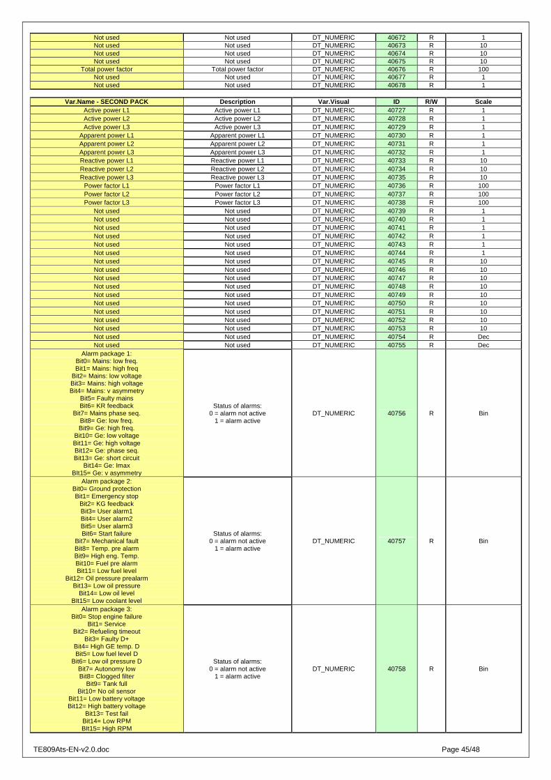
TE809Ats-EN-v2.0.doc Page 45/48
Not used Not used DT_NUMERIC 40672 R 1 Not used Not used DT_NUMERIC 40673 R 10 Not used Not used DT_NUMERIC 40674 R 10 Not used Not used DT_NUMERIC 40675 R 10
Total power factor Total power factor DT_NUMERIC 40676 R 100 Not used Not used DT_NUMERIC 40677 R 1 Not used Not used DT_NUMERIC 40678 R 1
Var.Name - SECOND PACK Description Var.Visual ID R/W Scale
Active power L1 Active power L1 DT_NUMERIC 40727 R 1 Active power L2 Active power L2 DT_NUMERIC 40728 R 1 Active power L3 Active power L3 DT_NUMERIC 40729 R 1
Apparent power L1 Apparent power L1 DT_NUMERIC 40730 R 1 Apparent power L2 Apparent power L2 DT_NUMERIC 40731 R 1 Apparent power L3 Apparent power L3 DT_NUMERIC 40732 R 1 Reactive power L1 Reactive power L1 DT_NUMERIC 40733 R 10 Reactive power L2 Reactive power L2 DT_NUMERIC 40734 R 10 Reactive power L3 Reactive power L3 DT_NUMERIC 40735 R 10
Power factor L1 Power factor L1 DT_NUMERIC 40736 R 100 Power factor L2 Power factor L2 DT_NUMERIC 40737 R 100 Power factor L3 Power factor L3 DT_NUMERIC 40738 R 100
Not used Not used DT_NUMERIC 40739 R 1 Not used Not used DT_NUMERIC 40740 R 1 Not used Not used DT_NUMERIC 40741 R 1 Not used Not used DT_NUMERIC 40742 R 1 Not used Not used DT_NUMERIC 40743 R 1 Not used Not used DT_NUMERIC 40744 R 1 Not used Not used DT_NUMERIC 40745 R 10 Not used Not used DT_NUMERIC 40746 R 10 Not used Not used DT_NUMERIC 40747 R 10 Not used Not used DT_NUMERIC 40748 R 10 Not used Not used DT_NUMERIC 40749 R 10 Not used Not used DT_NUMERIC 40750 R 10 Not used Not used DT_NUMERIC 40751 R 10 Not used Not used DT_NUMERIC 40752 R 10 Not used Not used DT_NUMERIC 40753 R 10 Not used Not used DT_NUMERIC 40754 R Dec Not used Not used DT_NUMERIC 40755 R Dec
Alarm package 1: Bit0= Mains: low freq. Bit1= Mains: high freq
Bit2= Mains: low voltage Bit3= Mains: high voltage Bit4= Mains: v asymmetry
Bit5= Faulty mains Bit6= KR feedback
Bit7= Mains phase seq. Bit8= Ge: low freq. Bit9= Ge: high freq.
Bit10= Ge: low voltage Bit11= Ge: high voltage Bit12= Ge: phase seq. Bit13= Ge: short circuit
Bit14= Ge: Imax BIt15= Ge: v asymmetry
Status of alarms: 0 = alarm not active
1 = alarm active DT_NUMERIC 40756 R Bin
Alarm package 2: Bit0= Ground protection Bit1= Emergency stop
Bit2= KG feedback Bit3= User alarm1 Bit4= User alarm2 Bit5= User alarm3 Bit6= Start failure
Bit7= Mechanical fault Bit8= Temp. pre alarm Bit9= High eng. Temp. Bit10= Fuel pre alarm Bit11= Low fuel level
Bit12= Oil pressure prealarm Bit13= Low oil pressure
Bit14= Low oil level BIt15= Low coolant level
Status of alarms: 0 = alarm not active
1 = alarm active DT_NUMERIC 40757 R Bin
Alarm package 3: Bit0= Stop engine failure
Bit1= Service Bit2= Refueling timeout
Bit3= Faulty D+ Bit4= High GE temp. D Bit5= Low fuel level D
Bit6= Low oil pressure D Bit7= Autonomy low Bit8= Clogged filter
Bit9= Tank full Bit10= No oil sensor
Bit11= Low battery voltage Bit12= High battery voltage
Bit13= Test fail Bit14= Low RPM BIt15= High RPM
Status of alarms: 0 = alarm not active
1 = alarm active DT_NUMERIC 40758 R Bin
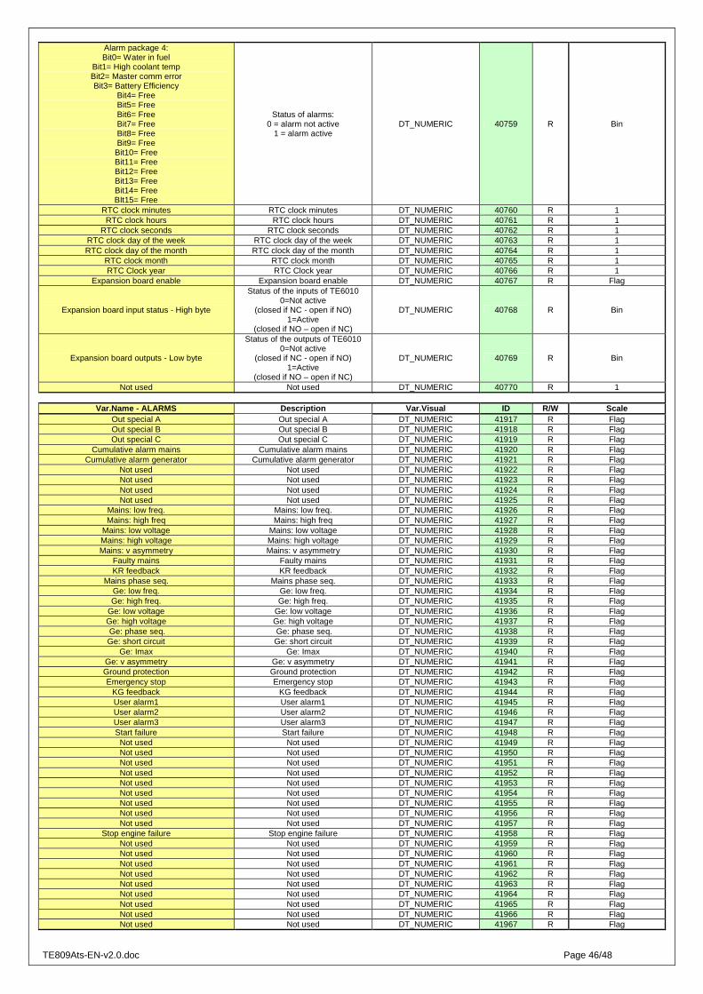
TE809Ats-EN-v2.0.doc Page 46/48
Alarm package 4: Bit0= Water in fuel
Bit1= High coolant temp Bit2= Master comm error Bit3= Battery Efficiency
Bit4= Free Bit5= Free Bit6= Free Bit7= Free Bit8= Free Bit9= Free Bit10= Free Bit11= Free Bit12= Free Bit13= Free Bit14= Free BIt15= Free
Status of alarms: 0 = alarm not active
1 = alarm active DT_NUMERIC 40759 R Bin
RTC clock minutes RTC clock minutes DT_NUMERIC 40760 R 1 RTC clock hours RTC clock hours DT_NUMERIC 40761 R 1
RTC clock seconds RTC clock seconds DT_NUMERIC 40762 R 1 RTC clock day of the week RTC clock day of the week DT_NUMERIC 40763 R 1 RTC clock day of the month RTC clock day of the month DT_NUMERIC 40764 R 1
RTC clock month RTC clock month DT_NUMERIC 40765 R 1 RTC Clock year RTC Clock year DT_NUMERIC 40766 R 1
Expansion board enable Expansion board enable DT_NUMERIC 40767 R Flag
Expansion board input status - High byte
Status of the inputs of TE6010 0=Not active
(closed if NC - open if NO) 1=Active
(closed if NO – open if NC)
DT_NUMERIC 40768 R Bin
Expansion board outputs - Low byte
Status of the outputs of TE6010 0=Not active
(closed if NC - open if NO) 1=Active
(closed if NO – open if NC)
DT_NUMERIC 40769 R Bin
Not used Not used DT_NUMERIC 40770 R 1
Var.Name - ALARMS Description Var.Visual ID R/W Scale Out special A Out special A DT_NUMERIC 41917 R Flag Out special B Out special B DT_NUMERIC 41918 R Flag Out special C Out special C DT_NUMERIC 41919 R Flag
Cumulative alarm mains Cumulative alarm mains DT_NUMERIC 41920 R Flag Cumulative alarm generator Cumulative alarm generator DT_NUMERIC 41921 R Flag
Not used Not used DT_NUMERIC 41922 R Flag Not used Not used DT_NUMERIC 41923 R Flag Not used Not used DT_NUMERIC 41924 R Flag Not used Not used DT_NUMERIC 41925 R Flag
Mains: low freq. Mains: low freq. DT_NUMERIC 41926 R Flag Mains: high freq Mains: high freq DT_NUMERIC 41927 R Flag
Mains: low voltage Mains: low voltage DT_NUMERIC 41928 R Flag Mains: high voltage Mains: high voltage DT_NUMERIC 41929 R Flag Mains: v asymmetry Mains: v asymmetry DT_NUMERIC 41930 R Flag
Faulty mains Faulty mains DT_NUMERIC 41931 R Flag KR feedback KR feedback DT_NUMERIC 41932 R Flag
Mains phase seq. Mains phase seq. DT_NUMERIC 41933 R Flag Ge: low freq. Ge: low freq. DT_NUMERIC 41934 R Flag Ge: high freq. Ge: high freq. DT_NUMERIC 41935 R Flag
Ge: low voltage Ge: low voltage DT_NUMERIC 41936 R Flag Ge: high voltage Ge: high voltage DT_NUMERIC 41937 R Flag Ge: phase seq. Ge: phase seq. DT_NUMERIC 41938 R Flag Ge: short circuit Ge: short circuit DT_NUMERIC 41939 R Flag
Ge: Imax Ge: Imax DT_NUMERIC 41940 R Flag Ge: v asymmetry Ge: v asymmetry DT_NUMERIC 41941 R Flag Ground protection Ground protection DT_NUMERIC 41942 R Flag Emergency stop Emergency stop DT_NUMERIC 41943 R Flag
KG feedback KG feedback DT_NUMERIC 41944 R Flag User alarm1 User alarm1 DT_NUMERIC 41945 R Flag User alarm2 User alarm2 DT_NUMERIC 41946 R Flag User alarm3 User alarm3 DT_NUMERIC 41947 R Flag Start failure Start failure DT_NUMERIC 41948 R Flag
Not used Not used DT_NUMERIC 41949 R Flag Not used Not used DT_NUMERIC 41950 R Flag Not used Not used DT_NUMERIC 41951 R Flag Not used Not used DT_NUMERIC 41952 R Flag Not used Not used DT_NUMERIC 41953 R Flag Not used Not used DT_NUMERIC 41954 R Flag Not used Not used DT_NUMERIC 41955 R Flag Not used Not used DT_NUMERIC 41956 R Flag Not used Not used DT_NUMERIC 41957 R Flag
Stop engine failure Stop engine failure DT_NUMERIC 41958 R Flag Not used Not used DT_NUMERIC 41959 R Flag Not used Not used DT_NUMERIC 41960 R Flag Not used Not used DT_NUMERIC 41961 R Flag Not used Not used DT_NUMERIC 41962 R Flag Not used Not used DT_NUMERIC 41963 R Flag Not used Not used DT_NUMERIC 41964 R Flag Not used Not used DT_NUMERIC 41965 R Flag Not used Not used DT_NUMERIC 41966 R Flag Not used Not used DT_NUMERIC 41967 R Flag

TE809Ats-EN-v2.0.doc Page 47/48
Not used Not used DT_NUMERIC 41968 R Flag Not used Not used DT_NUMERIC 41969 R Flag Not used Not used DT_NUMERIC 41970 R Flag Test fail Test fail DT_NUMERIC 41971 R Flag Not used Not used DT_NUMERIC 41972 R Flag Not used Not used DT_NUMERIC 41973 R Flag Not used Not used DT_NUMERIC 41974 R Flag Not used Not used DT_NUMERIC 41975 R Flag Not used Not used DT_NUMERIC 41976 R Flag Not used Not used DT_NUMERIC 41977 R Flag Not used Not used DT_NUMERIC 41978 R Flag
External trip External trip DT_NUMERIC 41979 R Flag Load breaker open Load breaker open DT_NUMERIC 41980 R Flag External Gen failure External Gen failure DT_NUMERIC 41981 R Flag Master comm error Master comm error DT_NUMERIC 41982 R Flag
TE 809G temperature alarm TE 809G temperature alarm DT_NUMERIC 41983 R Flag TE809G oil alarm TE809G oil alarm DT_NUMERIC 41984 R Flag
TE809G battery alarm TE809G battery alarm DT_NUMERIC 41985 R Flag TE809G fuel alarm TE809G fuel alarm DT_NUMERIC 41986 R Flag
TE809G service alarm TE809G service alarm DT_NUMERIC 41987 R Flag TE809G warning alarm TE809G warning alarm DT_NUMERIC 41988 R Flag
TE809G trip alarm TE809G trip alarm DT_NUMERIC 41989 R Flag Last alarm ID Last alarm ID DT_NUMERIC 42054 R Dec
Var.Name - COMMANDS Description Var.Visual ID R/W Scale
Manual mode Manual mode DT_NUMERIC 40539 W 1 Auto mode Auto mode DT_NUMERIC 40544 W 1 Reset mode Reset mode DT_NUMERIC 40549 W 1 Start engine Start engine DT_NUMERIC 40554 W 1 Stop engine Stop engine DT_NUMERIC 40559 W 1 Test mode Test mode DT_NUMERIC 40564 W 1
KG contactor KG contactor DT_NUMERIC 40569 W 1 KR contactor KR contactor DT_NUMERIC 40574 W 1
TE809Ats-EN-v2.0.doc Page 48/48
Authorized distributor