tds3tmt telecom mask test application module user … · tds3tmt telecom mask test application...
TRANSCRIPT

User Manual
TDS3TMT
Telecom Mask Test
Application Module
071-0648-02
����������071064802

Copyright� Tektronix. All rights reserved. Licensed software
products are owned by Tektronix or its subsidiaries or suppliers,
and are protected by national copyright laws and international
treaty provisions.
Tektronix products are covered by U.S. and foreign patents,
issued and pending. Information in this publication supercedes
that in all previously published material. Specifications and
price change privileges reserved.
TEKTRONIX, TEK, TEKPROBE, and TekSecure are registered
trademarks of Tektronix, Inc.
DPX, WaveAlert, and e*Scope are trademarks of
Tektronix, Inc.
Contacting Tektronix
Tektronix, Inc.
14200 SW Karl Braun Drive
P.O. Box 500
Beaverton, OR 97077
USA
For product information, sales, service, and technical support:
� In North America, call 1-800-833-9200.
� Worldwide, visit www.tektronix.com to find contacts in
your area.

1
Contents
Safety Summary 2. . . . . . . . . . . . . . . . . . . . . . . . . . . . .
Installing the TDS3TMT Application Module 5. . . . . . . .
Telecom Mask Test Features 5. . . . . . . . . . . . . . . . . . .
Accessing TDS3TMT: QuickMenu 6. . . . . . . . . . . . . . . .
Accessing TDS3TMT: Utility Menu 7. . . . . . . . . . . . . . .
Conventions 8. . . . . . . . . . . . . . . . . . . . . . . . . . . . . . .
TDS3TMT Menu 9. . . . . . . . . . . . . . . . . . . . . . . . . . . . .
Telecom Pass/Fail Mask Test Example 24. . . . . . . . . . . .

2
Safety Summary
To avoid potential hazards, use this product only asspecified. While using this product, you may need toaccess other parts of the system. Read the General SafetySummary in other system manuals for warnings andcautions related to operating the system.
Preventing Electrostatic Damage
CAUTION. Electrostatic discharge (ESD) candamage components in the oscilloscope and itsaccessories. To prevent ESD, observe theseprecautions when directed to do so.
Use a Ground Strap. Wear a grounded antistatic wrist strapto discharge the static voltage from your body whileinstalling or removing sensitive components.
Use a Safe Work Area. Do not use any devices capable ofgenerating or holding a static charge in the work areawhere you install or remove sensitive components.Avoid handling sensitive components in areas that have afloor or benchtop surface capable of generating a staticcharge.

3
Handle Components Carefully. Do not slide sensitivecomponents over any surface. Do not touch exposedconnector pins. Handle sensitive components as little aspossible.
Transport and Store Carefully. Transport and store sensitivecomponents in a static-protected bag or container.
Manual Storage
The oscilloscope front cover has a convenient place tostore this manual.

4

5
Installing the TDS3TMT Application Module
Refer to the TDS3000, TDS3000B, and TDS3000CSeries Application Module Installation manual forinstructions on installing and testing the applicationmodule.
Telecom Mask Test Features
The TDS3TMT application module adds waveformmask testing capabilities to your oscilloscope. Thissection provides an overview of these additional features.
Telecom Mask Test QuickMenu
Use the telecom mask test QuickMenu function todisplay bottom and side menus that provide access to allkey mask test functions from one screen.
Predefined Telecom Industry Masks
The TDS3TMT application module provides compliancemasks for testing to ITU-G.703 and ANSI T1.102telecommunications standards, up to STS-1 (52 Mb/s)line rates.
Multiple Channel Testing
The TDS3TMT application module enables you toperform multiple simultaneous testing on all activeoscilloscope channels.

6
Test Automation
You can connect the oscilloscope to do automated masktesting by using the RS--232, GPIB, or LAN commu-nication ports.
Accessing TDS3TMT: QuickMenu
1. Push theQuickMenu front-panel button to displaythe quick menu items.
2. Push theMenu bottom screen button to select anddisplay the Telecom bottom and side menu items.
3. Push bottom and side menu buttons to select a mask,set test control parameters, and test pass/failresponses.
7
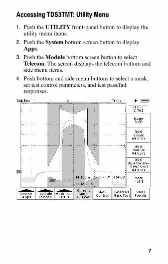
Accessing TDS3TMT: Utility Menu
1. Push the UTILITY front-panel button to display theutility menu items.
2. Push the System bottom screen button to displayApps.
3. Push theModule bottom screen button to selectTelecom. The screen displays the telecom bottom andside menu items.
4. Push bottom and side menu buttons to select a mask,set test control parameters, and test pass/failresponses.

8
Conventions
The following conventions apply to all TDS3TMTfunctions:
� You can perform multiple waveform mask testing byconnecting signals to all oscilloscope input channels.
� While in Telecom Mask test mode, the AUTOSET
front-panel button automatically sets the oscilloscopehorizontal, vertical, and trigger parameters, andpositions the waveform in the selected mask.
� Mask testing only works with live channels. It isrecommended that you turn off math and referencewaveforms while doing mask testing.

9
TDS3TMT Menu
Table 1: Utility Menu: Type = Apps, Module = Telecom
Bottom Side Description
Mask-Type(ITU-T)
None (Off)DS-0 Single 64 kb/sDS-0 Double 64 kb/sDS-0 Data Contra-directional 64 kb/s
DS-0 Timing 64 kb/sOld ”DS1” Rate1.544 Mb/s
G.703 DS11.544 Mb/s
E1 Symetric Pair2.048 Mb/s
E1 Coaxial Pair2.048 Mb/s
Clk Interface SymetricPair 2.048 Mb/s
Clk Interface CoaxialPair 2.048 Mb/s
”DS2” Rate SymetricPair 6.312 Mb/s
”DS2” Rate CoaxialPair 6.312 Mb/s
E2 8.448 Mb/s32.064 Mb/sE3 34.368 Mb/sOld ”DS3” Rate44.736 Mb/s
G.703 DS344.736 Mb/s
ITU-T standard masks. Eachmask sets the oscilloscopevertical, horizontal, andtrigger controls to acquirethat standard’s waveform.
After selecting a standard,push the AUTOSET front-panel button to position thewaveform in the mask.
The oscilloscope is set toedge trigger on waveforms(per ITU-T G.703 standard).

10
Table 1: Utility Menu: Type = Apps, Module = Telecom (cont.)
Bottom DescriptionSide
MaskType(T1.102)
None (Off)DS1 1.544 Mb/sDS1A 2.048 Mb/sDS1C 3.152 Mb/sDS2 6.312 Mb/sDS3 44.736 Mb/sSTS-1 Pulse51.84 Mb/s
ANSI T1.102 standardmasks. Each mask sets theoscilloscope vertical, hori-zontal, and trigger controls toacquire that standard’swaveform.
Mask None (Off) Turns off user mask.MaskType(Custom)
User Mask Sets the oscilloscope to usethe User mask.
Copy Std Mask ToUser Mask
Copies the selected ITU-T orT1.102 mask into the Usermask. Use the general pur-pose knob to select thestandard mask to load.
Save/Recall UserMask
Saves or recalls Usermasks.

11
Table 1: Utility Menu: Type = Apps, Module = Telecom (cont.)
Bottom DescriptionSide
CurrentMask
Status area that displays thename of the currently se-lected mask.
MaskControl
Highlight ViolationsOn Off
Turns on mask violationhighlighting. Waveforms thatviolate mask parametersleave highlighted points onthe mask that are the colorof the failing waveform.
Stop On ViolationOn Off
When set to On, the oscillo-scope stops mask testing onthe first occurrence of awaveform violation. Thisfunction overrules pass/failtests.
Lock Mask ToWaveformOn Off
Locks mask to waveform sothat the mask segmentsmove and redraw proportion-ally when changing thehorizontal or vertical scale orposition settings.
Autofit Search Radius Autofit repositions the wave-form using a spiral algorithmto attempt to fit the wave-form to a mask.

12
Table 1: Utility Menu: Type = Apps, Module = Telecom (cont.)
Bottom DescriptionSide
MaskControl
Vertical MarginPercentage(User mask only)
When enabled, adjusts theUser mask vertical marginsas a percent of the nominal(User mask only) as a percent of the nominalwaveform amplitude for themask standard.
Pass/FailMask
Pass/Fail Mask TestOn Off
When set to On, resets thestatus information and startsmask testing.Mask
Test Status: Displays pass/fail test statusinformation: the number ofwaveforms that have violatedthe mask per number ofwaveforms tested in thecurrent test, and the numberof failed tests per the totalnumber of tests run (if Re-peat on Completion is On).
If the number of waveformsthat fail exceeds the violationthreshold setting, status textchanges from Passing toFailing.
13
Table 1: Utility Menu: Type = Apps, Module = Telecom (cont.)
Bottom DescriptionSide
Pass/FailMaskTest
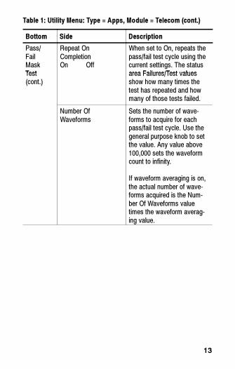
Repeat OnCompletionOn Off
When set to On, repeats thepass/fail test cycle using thecurrent settings. The statusarea Failures/Test valuesTest
(cont.)area Failures/Test valuesshow how many times thetest has repeated and howmany of those tests failed.
Number OfWaveforms
Sets the number of wave-forms to acquire for eachpass/fail test cycle. Use thegeneral purpose knob to setthe value. Any value above100,000 sets the waveformcount to infinity.
If waveform averaging is on,the actual number of wave-forms acquired is the Num-ber Of Waveforms valuetimes the waveform averag-ing value.

14
Table 1: Utility Menu: Type = Apps, Module = Telecom (cont.)
Bottom DescriptionSide
Pass/FailMaskTest
Violation ThresholdFor Failure
Sets how many failed wave-forms define a failed test.Use the general purposeknob to set the value.Test
(cont.) Pre-Test Delay Sets a time value that delaysthe start of a pass/fail test.Use the general purposeknob to set the value.
Polarity Sets the polarity of all activewaveform channels. Valuesare positive, negative, orboth. If set to Both, theoscilloscope tests the firsthalf of all active channelacquired waveforms in nor-mal (uninverted) mode, andthen inverts all active chan-nels and tests the secondhalf of acquired waveforms.
Beep On CompletionOn Off
When On, causes the oscil-loscope to emit a tone whenthe pass/fail test is complete.
Beep On FailureOn Off
When On, causes the oscil-loscope to emit a tone whenthe pass/fail test statuschanges from Passing toFailing.
15
Table 1: Utility Menu: Type = Apps, Module = Telecom (cont.)
Bottom DescriptionSide
Pass/FailMaskTest(cont.)
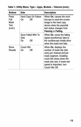
Hard Copy On FailureOn Off
When On, causes the oscil-loscope to send the screenimage to the hard copydevice when the pass/failtest status changes fromPassing to Failing.
Save Failed Wfm ToDiskOn Off
When On, saves the failingsignal waveform(s) data tothe oscilloscope media drivewhen the mask test fails.
ShowResults
Count HitsOn Off
When On, displays thenumber of mask hits (fail-ures) per channel and permask segment. Enablingcount hits slows down themask test rate; if mask testspeed is important, turnCount Hits Off.

16
Table 1: Utility Menu: Type = Apps, Module = Telecom (cont.)
Bottom DescriptionSide
ShowResults
Violations/Waveforms, ...
Displays pass/fail test statusinformation: the number ofwaveforms that have violatedthe mask per number ofwaveforms tested in thewaveforms tested in thecurrent test, and the numberof failed tests per the totalnumber of tests run (if Re-peat is On).
Segment 1 Hits. . .Segment 8 Hits
Status area that displays thenumber of hits for eachchannel on each mask seg-ment.
Mask Testing and Pass/Fail Testing.Mask testingmeans the detection and highlighting of mask segmentviolations. Pass/Fail testing is setting conditions for masktesting, such as the number of waveforms to test, howmany mask violations are allowed before failing a test,whether to repeat testing upon completion, what actionto perform at the completion of a test, and so on.
Turn Off Mask Testing. To turn off mask testing andremove the mask from the screen, set the mask standardto None.

17
Standards and Pulse Amplitudes. For those caseswhere a mask standard defines a valid pulse amplitude asbeing within a range of values, the TDS3TMT mask isdrawn for the maximum permitted amplitude.
For those cases where a mask standard does not definepulse amplitude, the TDS3TMT mask is drawn for anominal 1 V pulse.
Highlight Violations. Highlight Violations must be on inorder for the oscilloscope to perform mask comparisons.If Highlight Violations is off, the oscilloscope will notinform you of mask violations using highlighting or theStop On Violation command, and hits counting will notcount. Also, turning on pass/fail testing, Count Hits, orStop on Violation automatically turns on HighlightViolations.
Pass/Fail Testing: Averaging.When averaging is on,the oscilloscope first generates an averaged waveform,then the averaged waveform is compared to the mask.This means that the total number of waveforms acquiredis equal to the waveform averaging number times thenumber of waveforms being tested. For example, ifpass/fail Number of Waveforms is set to 500, andwaveform averaging is set to 8, then the total number ofwaveforms acquired for one pass/fail test cycle is500 x 8 = 4,000.
18
Saving Waveforms to Disk. The default saved file nameis TEKnnnnn.fff, where nnnnn is an incrementingnumber that usually starts at 00000, and fff is the fileformat (Internal, Spreadsheet, or Mathcad file format) asset in the SAVE/RECALL > Save Waveform to Filemenu. For internal file format waveforms (.isf), if morethan one waveform is being tested, look at the .isf filepreamble information at the top of the file to determinefrom which channel that waveform data came. Refer tothe TDS3000, TDS3000B, and TDS3000C SeriesProgrammer Manual for .isf file format information.
Proper Signal Termination.Make sure to correctlyterminate communication test signals. Tektronix offersoptional AMT75 adapters for correct communicationsignal termination.
Pass/Fail Testing: Polarity.When polarity is set to both,the oscilloscope tests the first half of all active channelacquired waveforms with positive polarity, and theninverts all active channels and tests the second half ofacquired waveforms.
Stop On Violation. If Stop On Violation is On, thepass/fail status area displays Violation if there is aviolation, regardless of the pass/fail test settings. In otherwords, Stop On Violation has a higher precedence thanpass/fail tests.

19
Running Mask Test Indefinitely. To run a mask testindefinitely while counting the number of violations, setNumber of Waveforms to infinity (∞).
Triggering. Selecting a mask standard automatically setstrigger parameters for that standard. However, to assignspecific trigger parameters to a mask (most likely for anew User mask), push the TriggerMENU button,selecting Comm, and selecting the mask standard to usefor triggering. The oscilloscope assigns the selectedstandard’s trigger parameters to the current mask.
Testing For Infrequent Errors. To automatically captureand save waveform violations that occur infrequentlyover long periods of time, set Pass/Fail testing Repeat toOn, Number of Waveforms to 1, and Hardcopy/Wfm OnFailure to On. You may also want to set UTILITY >Hard Copy > Options > Compression to ON tocompress the saved hardcopy data and thus store morefiles on the floppy disk. Compression is not available forwaveform (*.isf) format data.
20
On-Screen Mask Positions.Many of the mask standardshave their mask drawn on the right side of the graticuleto allow enough room to the left for acquiring sufficientserial trigger data.
When using the Lock Mask To Waveform feature, becareful not to move the mask too far left or else you maylose your serial trigger. Use Lock Mask To Waveformafter acquisitions have stopped to examine a maskviolation more closely.
To use Lock Mask to Waveform to make the mask fillmore of the screen, increase the acquisition record lengthby pushing ACQUIRE > Horizontal Resolution >Normal to set the record length to 10K points (note thatNormal mode only works with lock mode for horizontalsettings of 100 ns/div or faster). You can also use Zoomto examine a mask and waveform, provided that you panand zoom in such a way that there is enough space to theleft of the mask for the oscilloscope to detect the serialtrigger.

21
Autofit Key Points. The following are some Autofit-spe-cific key points:
� The Autofit radius defines the size of a square searchgrid radius of (2 ¢ radius + 1)¢ (2 ¢ radius + 1)pixels, centered on the waveform position. Autofitmoves the waveform using a spiral pattern, testing formask violations at each position. For example, thefollowing table represents a spiral pattern for a radiusvalue of 2, where the number represents the order ofthe waveform moves, and the position of the numberrepresents the position the waveform is offset relativeto the starting point (s). A radius of two attempts to fitthe waveform in 25 tries (start position plus 24).
9 10 11 12 13
24 1 2 3 14
23 8 s 4 15
22 7 6 5 16
21 20 19 18 17
� If pass/fail testing is used in conjunction with Autofit,the Autofit center point is reset at the beginning ofeach pass/fail test.
� Autofit is most appropriate when the waveform(s)being tested is already close to fitting inside the mask.

22
� When Autofit moves the waveform, it only movesthe location where the waveform is drawn on thedisplay. It does not change any of the underlyingvertical, horizontal, or trigger parameters used toacquire the waveform.
A consequence of this is that when moving thewaveform left (or right), the waveform points at theright (or left) edge of the screen will be blank if thehorizontal settings are such that the entire acquiredwaveform is displayed on screen. This is acceptablebecause those points are typically outside the maskregion.
� If the waveform is a significant distance from themask, AUTOSET should be used first to adjust thevertical, horizontal, and trigger parameters.
� When numerous waveforms are violating the maskby substantial amounts, thereby causing Autofit torun almost continuously, the instrumentresponsiveness is significantly degraded. This isanother reason why AUTOSET is more appropriatethan Autofit for waveforms which violate the maskby large amounts.

23
Automated Pass/Fail Testing Process. The recom-mended automated pass/fail testing process is:
1. Set the oscilloscope to default settings using theSAVE/RECALL-->Recall Factory Setup menu.
2. Set the Graticule type to Frame(DISPLAY-->Graticulemenu).
3. Select the mask standard.
4. Turn off all waveforms not being tested.
5. Connect the appropriate input signals.
6. Push the Autoset button.
7. Set Autofit to a reasonably small value, such as 4.
8. Set Polarity to Both.
9. Set the number of Waveforms to 100.
10.Run the pass/fail test.
11.Note the pass/fail test status (Passed or Failed) andtake appropriate action.
12.Connect new signals.
13.Repeat from step 10.

24
Telecom Pass/Fail Mask Test Example
In this example, you want to test an ITU-T telecomsignal that needs to meet the E1 Coaxial Pair 2.048 Mb/sstandard. You want to highlight any waveform maskerrors, as well as set up pass/fail testing to test 500waveforms, then stop.
Use the Telecom QuickMenu to set the TDS3TMT maskparameters as listed in the table. Connect the signal toCH 1 on the oscilloscope, then press the AUTOSETfront-panel button. After Autoset completes, press theRun Test side menu button to perform the pass/fail test.
Telecom QuickMenu
Menu Item Parameter Value
Standard Use buttons to scrollthrough mask stan-dard list
E1 Coax (ITU-T)2.048 Mb/s
Control Highlight OnControl
Average Off
Wfm Lock Off
Autofit On (≥1)

25
Telecom QuickMenu (cont.)
Menu Item ValueParameter
Pass/Fail Send hardcopy toprinter
Off (unchecked)
Send waveform to file Off (unchecked)
Beep on failure On (checked)
Beep on completion On (checked)
Repeat test Off (unchecked)
Waveforms 500
Threshold 1
Polarity Positive
Use the upper menu button to select a response, and thenuse the lower menu button to enable or disable theselected response. You can select and enable any com-bination of responses.