tcp/ipv4 and ethernet 10base-t/ 100base-tx … · frame instead of packet. some packets are...
TRANSCRIPT

IntroductionThe Internet changes the way we work and play by providing instant information and worldwide access to products and services. The Internet is a global network of computers that can communicate with each other using Internet Protocol Suite standards. Because of the Internet popularity and its ease of use there is a growing number of embedded products from cameras to instruments that are connected to the Internet. Designing these embedded products is challenging and time consuming without the right verification and debug tools.
The mixed signal oscilloscope (MSO) is the tool of choice to debug embedded systems that have a mixture of analog and digital signals. For quick verification and debugging the MSO4000B Series Oscilloscope with the DPO4ENET Serial Application Module captures and decodes TCP/IPv4/Ethernet protocol and data on 10BASE-T/100BASE-TX local area networks (LANs). The MSO4000B Series Oscilloscope provides embedded system visibility of time correlated analog signals, digital signals, parallel buses, serial buses and the LAN interface to the Internet.
All references to the MSO/DPO4000B with DPO4ENET in this application note refer to the MSO/DPO4000B Series Oscilloscope with the DPO4ENET Serial Application Module. The Internet example used in this application note is a laptop computer running Microsoft Internet Explorer (IE) that uses the Internet to control an instrument. In this case the instrument is a second MSO4104B that operates as an embedded web server.
This application note begins with an overall view of the operation of the Internet Protocol Suite which is the foundation of the Internet implementation. Next, the operation of each Internet Protocol layer is discussed. Throughout the application note the MSO/DPO4000B with DPO4ENET is used to show the examples of the protocol with its data. At the end of this application note is a section on working with Ethernet 10BASE-T and 100BASE-TX signals with the MSO/DPO4000B with DPO4ENET.
TCP/IPv4 and Ethernet 10BASE-T/ 100BASE-TX Debugging with the MSO/DPO4000B Series OscilloscopesApplication Note

Application Note
www.tektronix.com/ethernet2
Internet Protocol Suite The operation of the Internet is based on the Internet Protocol Suite. Protocols are rules and procedures that define the information format, the process of transmitting information and the process of receiving information. Internet Protocol Suite is organized into four layers of protocols: Application layer, Transport layer, Internet layer and Link layer1 (see Table 1). These layers use various protocol standards. The standards used in this application note are Hypertext Transfer Protocol (HTTP) for the Application layer, Transmission Control Protocol (TCP) for the Transport layer, Internet Protocol version 4 (IPv4) for the Internet layer and Ethernet 10BASE-T and 100BASE-TX for the Link layer. These protocol standards provide networking interoperability among different equipment on the Internet.
Figure 1 shows Microsoft Internet Explorer (IE) in the application layer requesting the web page from network device (oscilloscope). The request begins with the IE Hypertext Transfer Protocol2 (HTTP) client in the Application layer on the laptop. Each protocol layer encapsulates the information from the layer above it with its protocol. Therefore, TCP, IPv4 and
Ethernet 10BASE-T protocol information is added to the IE web page request as it progresses down through its Internet Protocol layers on the laptop.
On the bottom of Figure 1 the Ethernet 10BASE-T twisted pair wires carry the electrical signals between the laptop and oscilloscope. The MSO/DPO4000B with DPO4ENET captures the electrical signals and decodes the three lower protocol layers as is shown in the compressed bus waveform in the bottom of Figure 1.
Figure 1. Internet protocol layers communicate with same protocol layer on other network nodes and the layers above and below it.
Table 1. Internet Protocol Suite Layers.
Internet Layer Protocol
Application Hypertext Transfer Protocol (HTTP)
Transport Transmission Control Protocol (TCP)
Internet Internet Protocol version 4 (IPv4)
Link Ethernet 10BASE-T & 100BASE–TX

www.tektronix.com/ethernet 3
TCP/IPv4 and Ethernet 10BASE-T/100BASE-TX Debugging with the MSO/DPO4000B Series Oscilloscopes
In the oscilloscope each of protocol layers message information is decoded and processed as the web page request travels up the Internet protocol layers to the HTTP server in the Application layer. Upon receiving the web page request the oscilloscope HTTP server replies by sending a HyperText Markup Language (HTML) file to the laptop. This HTML file travels down the oscilloscope Internet protocol layers, across the twisted pair wires and up the laptop Internet protocol layers to the IE application. IE displays the oscilloscope HTML file upon receiving it (see Figure 2).
TCP can work with many applications at the same time. Figure 3 shows TCP having two ports to work with two different application types. In this case port 80 is for HTTP and port 20 is for File Transfer Protocol (FTP).
In Figure 3 the bottom three layers use a formatted unit of information called a packet. Ethernet standard uses the term frame instead of packet. Some packets are composed of a header field and a data field. Usually lower protocol packets encapsulate higher level packets in their data fields. For example, a TCP packet with an HTTP application message is in the IPv4 data field. The IPv4 packet is in an Ethernet 10BASE-T or 100BASE-TX frame data field (see Figure 3).
To quickly identify different packet fields the MSO/DPO4000B with DPO4ENET decode uses the following color codes. See Figure 4.
Start of an Ethernet frame is a green vertical bar
Ethernet Preamble (PRE) and Start of Frame Delimiter (SFD) are purple
Ethernet header is yellow
IPv4 header is white
TCP header is brown
Data is cyan
Ethernet Frame Check Sequence (FCS) is purple
End of Ethernet frame is a red vertical bar
Figure 2. Web display in Internet Explorer.
Figure 4. MSO/DPO4000B color coded decode bus display showing data encapsulation.
Figure 3. TCP ports to different application types and data encapsulation between layers.

Application Note
www.tektronix.com/ethernet4
Hypertext Transfer Protocol (HTTP)Starting at the top Application layer, HTTP is one of the core protocols of the World Wide Web. A web browser uses HTTP to obtain formatted information from HTTP servers. The web browser is a client and it uses HTTP to request HTML files, images, movies, forms, etc. from a HTTP server. The HTTP server can be a web site on a network server or an embedded systems device like a web camera or a instrument.
Both IE and the oscilloscope understand HTTP and HTML protocol and they successfully work together. Also, the IE HTTP client and the oscilloscope HTTP server are Application layers that know how to work with their Transport layers below them in order to communicate to the other device (see Figure 1).
Transmission Control Protocol (TCP)Transmission Control Protocol4 (TCP) is a widespread protocol used in the Transport layer of the Internet Protocol Suite. TCP reliably exchanges data between network nodes. TCP is responsible for guarantee packet delivery, proper packet sequencing, packet acknowledgment, avoidance of duplicate packet delivery and packet integrity.
The TCP packet contains a header with 10 fields plus an optional extension field. The TCP packet includes information on the port number, flags, sequencing numbers, etc. (see Table 2). The port number allows multiple connections between two network nodes. Different applications types use different ports between the Application layer and the TCP.
Table 2. TCP packet format.
Header Offset Field Name
0-15 bits Source port: 2 bytes
16-31 bits Destination port: 2 bytes
32-63 bits Sequence number: 4 bytes
64-95 bits Acknowledgment number: 4 bytes
96-99 bits Data offset: 4 bits
100-103 bits Reserved: 4 bits
104-111 bits Eight Flags: 8 bits
112-127 bits Window: 2 bytes
128-143 bits Checksum: 2 bytes
144-159 bits Urgent pointer: 2 bytes
160-… bits Options
Figure 5. In this Ethernet 10BASE-T acquisition the TCP packet starts with source port number 81.

www.tektronix.com/ethernet 5
TCP/IPv4 and Ethernet 10BASE-T/100BASE-TX Debugging with the MSO/DPO4000B Series Oscilloscopes
Internet Protocol (IPv4)Internet Protocol5 version 4 (IPv4) is used in the Internet Protocol Suite Internet layer. Computers and devices use IPv4 addresses to locate and talk to each other on the Internet. The IPv4 address identifies the network and a unique network node.
IPv4 transports packets from the source network node to the destination network node on the Internet. This works across network boundaries and uses gateways between networks. In order to accomplish this task IPv4 handles the addressing and packet routing.
IPv4 address is a logical address that is independent of the hardware addressing of the LAN and works with different LAN implementations. IPv4 maps the logical address to the hardware address. IPv4 address is unique and it can include a network number, subnet number and a network node number. IPv4 address is composed of four-bytes (32-bit) and is written in dot-decimal notation. Each byte is shown in decimal and is separated by periods. A byte ranges from 0 to 255 decimal.
The IPv4 packet contains header fields and a data section. The IPv4 fields are Protocol, IPv4 Source Address, IPv4 Destination Address, data fields, etc. (see Table 3).
Link LayerThe bottom layer in the Internet Protocol Suite is the Link layer which provides the physical interface between network nodes. The interface can be electrical wiring, optical fiber or wireless. Data is transferred between network nodes based on a physical hardware address.
A popular link layer implementation is Ethernet 10BASE-T and 100BASE-TX. Ethernet 10BASE-T and 100BASE-TX are supported by most computers. The popularity of 10BASE-T and 100BASE-TX and their decreasing hardware implementation cost has caused them to be incorporated in embedded systems such as the cameras, security systems, instruments, etc.
Table 3. IPv4 packet format.
Header Offset Field Name
0-3 bits Version
4-7 bits Internet Header Length (IHL)
8-13 bits Differentiated Services Code Point (DSCP)
14-15 bits Explicit Congestion Notification (ECN)
16-31 bits Total Length
32-47 bits Identification
48-50 bits Flags
51-63 bits Fragment Offset
64-71 bits Time To Live (TTL)
72-79 bits Protocol
80-95 bits Header Checksum
12-15 bytes IPv4 Source Address
16-19 bytes IPv4 Destination Address
20-23 bytes Options
20 or 24 bytes Data
Figure 6a. MSO/DPO4000B with DPO4ENET decodes IPv4 packets and triggers on IPv4 packet fields. This Ethernet 10BASE-T acquisition shows the first IPv4 field is version 4, the second field is Internet Header Length 5, etc.
Figure 6b. IPv4 protocol field is TCP which means a TCP message is in the IPv4 data field.
Application Note
www.tektronix.com/ethernet6
Ethernet The Ethernet frame is a basic unit of data transfer on the LAN and the frame flows in a one direction.
Ethernet frame is a sequence of seven fields. Ethernet frame includes information on the Ethernet source address, destination address, packet size, length/frame type and data (see Table 4). The Ethernet frame size has a minimum length in order for collision detection to work in half duplex mode.
The frame transmission begins with a Preamble (PRE) and the PRE is used by a 10BASE-T receiver for start-up synchronization. The PRE is at least seven bytes long and is an alternating pattern of ones and zeros (see Figure 7).
The PRE starts with one and ends with zero. The first PRE bit (one) may have phase violations or invalid amplitude since it is starting from zero volts. Also, some PRE implementations may have additional one-zero pairs beyond the required seven bytes.
100BASE-TX has the same PRE field for backward compatibility but does not need the PRE for receiver synchronization because the 100BASE-TX electrical encoding is different than 10BASE-T. The 10BASE-T signals are zero when the 10BASE-T frame is not transmitting. The 100BASE-TX transmits an idle signal between frames and never stops transmitting like 10BASE-T. Therefore, 100BASE-TX receiver always has a signal for keeping synchronization.
The Start-of-frame Delimiter (SFD) indicates the start of a frame after it and the SFD immediately follows the PRE. The SFD is the second part of the PRE. The SFD is one byte long with pattern of 10101011. The frame fields follow the SFD.
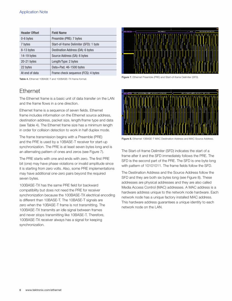
The Destination Address and the Source Address follow the SFD and they are both six bytes long (see Figure 8). These addresses are physical addresses and they are also called Media Access Control (MAC) addresses. A MAC address is a hardware address unique to the network node hardware. Each network node has a unique factory installed MAC address. This hardware address guarantees a unique identity to each network node on the LAN.
Table 4. Ethernet 10BASE-T and 100BASE–TX frame format.
Header Offset Field Name
0-6 bytes Preamble (PRE): 7 bytes
7 bytes Start-of-frame Delimiter (SFD): 1 byte
8-13 bytes Destination Address (DA): 6 bytes
14-19 bytes Source Address (SA): 6 bytes
20-21 bytes Length/Type: 2 bytes
22 bytes Data+Pad; 46-1500 bytes
At end of data Frame check sequence (FCS): 4 bytesFigure 7. Ethernet Preamble (PRE) and Start-of-frame Delimiter (SFD).
Figure 8. Ethernet 10BASE-T MAC Destination Address and MAC Source Address.

www.tektronix.com/ethernet 7
TCP/IPv4 and Ethernet 10BASE-T/100BASE-TX Debugging with the MSO/DPO4000B Series Oscilloscopes
MAC address is organized into groups of two hexadecimal digits. 10BASE-T and 100BASE-TX transmits the MAC address bytes from left-to-right with least significant bit in each byte first.
The Destination Address can contain a Multicast address representing a group of network nodes. All network nodes part of the multicast address will receive the frame. Also, all network nodes will receive a Broadcast address which is address of all one’s (FF:FF:FF:FF:FF:FF). In Figure 9 the MSO/DPO4000B with DPO4ENET captured a Broadcast and it is decode as an event table. The Event table can be saved for documentation and for analysis by other tools.
The IEEE Registration Authority allocates and registers Organizationally Unique Identifiers (OUI). The OUI is the first three bytes of the MAC address. The OUI is assigned to a manufacturer of Ethernet interfaces. For example, the OUI 08-00-11 is assigned to Tektronix, Inc. The manufacturer
uses the last three MAC address bytes to identify a specific Ethernet interface. Therefore, an Ethernet interface MAC address is unique on a LAN.
The Length/Type field is the number of Logical Link Control (LLC) bytes if equal or less than 1,500 (05DC hexadecimal). Length/Type is a type if it is greater than 1536 (0600 hexadecimal). For example, type 2,048 (0800 hexadecimal) is the Internet protocol as is shown in Figure 10 and type 33,024 (8100 hexadecimal) is Virtual LAN (VLAN).
The Ethernet frame data is 46 to 1500 bytes. If the data is less than 46 bytes the data field is filled with a pad to become 46 bytes long. This pad makes sure the total packet length is long enough to recognize a collision for a round trip delay of 50 microseconds.
The Frame Check Sequence (FCS) is four bytes long (32-bit) cyclic redundancy check (CRC) value used for error detection. The CRC includes Destination Address, Source Address, Length/Type, Data and Pad fields. The FCS MSB is transmitted first and the LSB is transmitted last.
An idle signal (TP_IDL) is transmitted when 10BASE-T packets are not being transmitted. At the end of the 10BASE-T FCS may be a start of idle (TP_IDL). A TP_IDL always starts with a one at the end of the FCS and stays one for two bit times (at least 250 ns for 10BASE-T, see Figure 10).
Figure 10. Ethernet 10BASE-T Length/Type (MAC Type) with the Internet protocol type 0800 hexadecimal. After the Length/Type is the Ethernet frame data field which contains the IPv4 packet.
Figure 11. 10BASE-T four byte FCS Frame check sequence (FCS) with TP_IDL signal at the end.
Figure 9. Ethernet broadcast address FF:FF:FF:FF:FF:FF from MAC address 00:D0:C9:B9:C8:0D. The second line of the Event table shows the IPv4 packet contains a UDP packet.

Application Note
www.tektronix.com/ethernet8
After the start of TP_IDL there are no transitions (differential voltage remains at 0 mV ± 50 mV) until the next Ethernet frame or link test signal. During TP_IDL the 10BASE-T link test is transmitted every 16 ms ±8 ms. The link test signal is a positive pulse 585 mV to 3.1V and it is a minimum of ~60 ns wide and a maximum of ~200 ns wide.
Between Ethernet frames are interframe gaps (IFG) of 96 bits. The 10BASE-T IFG is 9.6 µs and the 100BASE-TX IFG is 960 ns. When a network node transmits multiple frames it must wait for a period equal to the IFG between each frame before transmitting the next frame.
10BASE-TEthernet 10BASE-T defines a specific physical connection between networks nodes. 10BASE-T uses Category 3 (CAT3) cable or better with two unshielded twisted-pair (UTP) wires. These twisted-pair wires are referred to as the media in the IEEE specifications. One pair is for transmit and the other pair is for receive. Each pair is a differential signal. None of the cable wires are connected to ground at the network nodes.
10BASE-T Manchester CodeEthernet 10BASE-T is Manchester encoded data in which data and clock signals are combined to form a single self-synchronizing data stream. A transition always occurs in the middle of each bit and the bit cell period is 100 ns. The first half of the bit is the complement of the last half of the bit. As a result, 10BASE-T has no DC component.
The IEEE Std 802.3TM-2008 Manchester encoded data defines the middle bit rising edge as a logical one and the middle bit falling edge as a logical zero. In other words, a logical one is a high voltage at the end of the bit and a logical zero is a low voltage at the end of the bit (see Figure 13).
Figure 12. During 10BASE-T IDLE the link test pulse is transmitted every 16 ms ±8 ms.
Figure 14. Ethernet 10BASE-T Manchester encoded address with the least significant bit first in the byte.
Figure 13. Ethernet 10BASE-T Manchester 11000101 coding with a transition in the middle of each bit.

www.tektronix.com/ethernet 9
TCP/IPv4 and Ethernet 10BASE-T/100BASE-TX Debugging with the MSO/DPO4000B Series Oscilloscopes
An all ones burst or all zero burst is a 10 MHz waveform (see Figures 15 and 16). The difference between all ones and all zeros is the phase of the square wave which is very difficult to determine in the middle of a data stream. The MSO/DPO4000B with DPO4ENET saves your time by automatically decoding the Ethernet 10BASE-T Manchester coded signal after each acquisition.
Working with Ethernet 10BASE-TThe MSO/DPO4000B Series Oscilloscope with DPO4ENET Serial Application Module triggers, decodes and searches on TCP, IPv4 and Ethernet frame protocol on 10BASE-T and 100BASE-TX signals. Table 5 shows the recommend equipment configurations for 10BASE-T and 100BASE-TX signals.
The CAT5 cable does not have a ground reference signal. Therefore, a TDP0500 Differential Probe accesses 10BASE-T signals using a Fluke Networks 8-Wire In-Line Modular Adapter (10230100). AutoZero the TDP0500 probe before connecting it to 10BASE-T signals by attaching both probe inputs to the oscilloscope front panel Probe Comp ground. Next, select the TDP0500 4.25 V scale and AutoZero the probe. The TDP0500 D+ is connected to pin 1 and TDP0500 D- is connected to pin 2.
There are two methods to quickly check that the TDP0500 probe is connected correctly. The first method, the link test pulse is a solitary positive pulse when the 10BASE-T LAN is in the idle state. The link test pulse first goes positive (minimum 585 mV and maximum of 3.1 V) for minimum of 60 ns (Figure 18). In the idle state link test pulses repeat 16 ms ±8 ms and between the link pulses the signal is at 0 mV ± 50 mV (see Figure 12).
Figure 15. An Ethernet 10BASE-T Manchester code of all ones is a 10 MHz waveform.
Table 5. 10BASE-T and 100BASE–TX recommend equipment configuration.
Figure 16. An Ethernet 10BASE-T Manchester code of all zeros is a 10 MHz waveform. All zeros pattern is different from an all ones pattern by the phase offset.
Figure 17. Fluke 8-Wire In-Line Modular Adapter.
Ethernet Oscilloscope ProbeSerial Application
Module
10BASE-T100BASE-TX
MSO/DPO4104BMSO/DPO4054BMSO/DPO4034B
TDP0500 500 MHz Differential
ProbeDPO4ENET
Figure 18. Positive link pulse confirms the differential probe is correctly connected to the Ethernet 10BASE-T twisted pair.

Application Note
www.tektronix.com/ethernet10
The second method, at the end of a FCS there might be a TP_IDL signal that starts with a one and is one for 2-bit times (200 ns). Therefore, the TP_IDL signal is a minimum of 250 ns and is positive (see Figure 19).
The MSO/DPO4000 vertical scale is set so that differential signal fills the vertical display as much as possible without clipping the waveform. A good starting point is 500 mV/ division and you might need to adjust the vertical Fine Scale. The oscilloscope bus decoding requires a minimum of eight to ten samples for each bit period for successful decoding. Therefore, 100 MS/s is the slowest sampling rate used for decoding a clean 10BASE-T signal (see Table 6).
The Ethernet 10BASE-T frame without the PRE, SFD and TP_IDL has a maximum of 1,518 bytes (1.2144 ms) when not including a Virtual LAN (VLAN) tag header (four-bytes). The oscilloscope is set to 1M record length and the horizontal scale is set to 1 ms/division. As result, the Ethernet 10BASE-T signal is sampled at 100 MS/s and the acquisition time span is 10 ms which will capture the complete packet if it is at the maximum 1.2144 ms packet size.
The front panel blue Bus buttons are used to define an Ethernet 10BASE-T bus by entering the bus parameters which includes selecting 10BASE-T, differential probe, thresholds and turning on/off TCP/IPv4 decoding. A good starting point for 10BASE-T thresholds is the preset values 500 mV for logic high and -500 mV for logic low. The Low threshold is the same as the front panel Trigger Level and changing one will change the other. The oscilloscope is configured to trigger on SDF and is put in Single acquisition mode (see Figure 20).
Figure 19. Two bit positive TP_IDL signal at the end of the Ethernet 10BASE-T frame confirms the differential probe is correctly connected to the Ethernet 10BASE-T twisted pair.
Figure 20. Ethernet 10BASE-T frame acquisition triggered on SFD.
Table 6. Minimum sampling rate requirements to decode 10BASE-T and 100BASE–TX.
Ethernet Bit PeriodMinimum Scope Sampling Rate
Time Span at 20 M record length
10BASE-T 100 ns 100 MS/s 200 ms
100BASE-TX 8 ns 1 GS/s 20 ms

www.tektronix.com/ethernet 11
TCP/IPv4 and Ethernet 10BASE-T/100BASE-TX Debugging with the MSO/DPO4000B Series Oscilloscopes
In Figure 21 the cursors are used to measure the interframe gap (IFG) of 96 bits which is equal to 9.6 µs. Also, a collision occurred in the middle of the preamble (PRE) of the top 10BASE-T waveform and the start of the bottom 10BASE-T waveform. Both network nodes recognized the collision and stopped transmitting.
After the first collision the bottom channel waited for 12.68 µs before started transmitting and the top channel waited for 15.88 µs before transmitting that resulted in a second collision as shown in Figure 22. After the second collision the bottom 10BASE-T signal was successful in transmitting its packet.
100BASE-TXEthernet 100BASE-TX is part of the Fast Ethernet standards that carry traffic at the nominal rate of 100 Mbit/s over Category 5 (CAT5) or better cable. In the CAT5 cable 100BASE–TX uses one pair for transmission and another pair for collision detection and receive. 100BASE–TX operates in half-duplex or full-duplex mode just like 10BASE-T.
Figure 21. Ethernet 10BASE-T frame acquisition interframe gap is measured at 9.6 µs with the cursors and a collision between the two signals.
Figure 22. Ethernet 10BASE-T frame acquisition interframe gap is 12.68 µs on the bottom 10BASE-T waveform after the first collision. A second collision occurred on the right side of the display after the bottom channel started transmitting its PRE.

Application Note
www.tektronix.com/ethernet12
100BASE-TX 4B5B, Scrambling and MLT-3 CodeEthernet 100BASE-TX encoding is based on ANSI X3.263-1995 (TP-PMD) standard. The transmission goes through three transformations. First, the transmission is 4B5B binary encoded to prevent a string of zeros that may cause the receiver to lose clock synchronization lock. Second the transmission is scrambled to minimize electromagnetic emissions. Last the transmission in encoded with Multi-Level Transmit -3 (MLT-3) to reduce the high frequency content of the signal. These three transformations make it almost impossible to hand decode a 100BASE-TX signal.
4B5B binary encoding is used to prevent a long string of zeros resulting in no data edges for the receiver clock synchronization. See Table 7. 4B5B binary encoding transforms four bits into five bits with a data pattern of a maximum of one leading zero and a maximum of two trailing zeros. The bit rate changes from the 4B5B input of 100 Mbps (10 ns per bit) to 125 Mbps (8 ns per bit) at the output.
The four bit data uses 16 five bit output codes. This leaves 16 other output codes to be used for protocol. For example, see Table 8 that shows output codes definitions for IDLE (I), Control (J, K, T and R) and Transmit Error (H). The rest of the unused five bit output codes are undefined and are invalid codes.
Table 7. 100BASE–TX 4b5b encoding.
Table 8. 100BASE–TX symbols.
Hex Data Input 4b Output 5b
0 0000 11110
1 0001 01001
2 0010 10100
3 0011 10101
4 0100 01010
5 0101 01011
6 0110 01110
7 0111 01111
8 1000 10010
9 1001 10011
A 1010 10110
B 1011 10111
C 1100 11010
D 1101 11011
E 1110 11100
F 1111 11101
Symbols Description Output
I IDLE 11111
J Start #1 11000
K Start #2 10001
T End 01101
R Reset 00111
H Transmit Error 00100

www.tektronix.com/ethernet 13
TCP/IPv4 and Ethernet 10BASE-T/100BASE-TX Debugging with the MSO/DPO4000B Series Oscilloscopes
The 100BASE–TX link integrity is verified by the reception of the IDLE symbol which is transmitted between frames. Also, the IDLE symbol maintains receiver clock synchronization.
The 100BASE–TX Start-of-Stream delimiter (SSD) is before the Ethernet frame PRE and is the symbol sequence J followed by K. The 100BASE–TX End-of-Stream Delimiter (ESD) follows the Ethernet frame FCS and is the symbol sequence T followed by R. The H symbol is used to propagate receive errors.
After 4B5B encoding the transmission is scrambled to minimize electromagnetic emissions. The scrambled transmission results in different waveform patterns for the same data values being sent at different times. See Figures 23 and 24.
The Multi-Level Transmit-3 (MLT-3) encoding uses three voltage levels (three states). MLT-3 cycles consecutively through the states -1, 0, +1, 0, -1, 0, +1, 0, etc. Logic high causes a move to the next state and logic low results in staying in the same state.
The four bit input symbol rate is 100 Mbps (10 ns/bit) and the 4B5B output symbol rate is 125 Mbps (8 ns/bit). After MLT-3 encoding the maximum fundamental frequency is 31.25 MHz. See Figure 25.
For Unshielded Twisted Pair cable the MTL-3 differential signal is from 950 mV to 1050 mV.
Figure 24. 100BASE-TX scrambled waveform. Compare this waveform with Figure 23 which is the same data at a different time with a different waveform.
Figure 25. 100BASE-TX MLT-3 encoding maximum fundamental frequency is 31.25 MHz.
Figure 23. 100BASE-TX scrambled waveform. Compare this waveform with Figure 24 which is the same data at a different time with a different waveform.

Application Note
www.tektronix.com/ethernet14
Working with Ethernet 100BASE-TThe 100BASE-TX probing configuration is the same as 10BASE-T in the previous section. As is shown in Table 9 the minimum recommended sampling rate is 1 GS/s for 100BASE-TX. The MSO/DPO4000B maximum time span at 1 GS/s is 20 ms when the MSO/DPO4000B is configured for 20 Mpoint record length and 2.00 ms/division. The trigger is set to Ethernet 100BASE-TX Start of Frame (SFD) and a single acquisition was taken.
The MSO/DPO4000B Series Oscilloscopes all have up to a 20 Mpoint waveform record on all channels. This is over 20,000 full resolution screens of data. It takes over five and a half hours to scroll through a 20 Mpoint waveform at the rate of one full resolution screen (1,000 points) per second. MSO/DPO4000B Wave Inspector is a search and navigation function that simplifies the task of working with large acquisitions. The MSO/DPO4000B trigger and search functions are integrated in that the trigger settings are copied to search and the search settings are copied to trigger. In this case the Ethernet 100BASE-TX Start of Frame trigger setting is copied to the search. The Wave Inspector searched and marked all ten SFDs in the 20 Mpoint record in a few seconds. The SFD marks are the white hollow triangles above the waveforms in Figure 26. Notice that 100BASE-TX transmits a continuous IDLE symbol and the twisted pair wires are always active which makes it very difficult to visually find the packets in the 20 Mpoint acquisition without the marks. Now that the SFD has been found and marked, navigating between Start of Frame occurrences is as simple as pressing the Wave Inspector front-panel Previous and Next arrow buttons.
Table 9. MSO/DPO4000B Series Oscilloscopes with the DPO4ENET Serial Application Module 10BASE-T Triggering and Searching
Table 10. MSO/DPO4000B Series Oscilloscopes with the DPO4ENET Serial Application Module 100BASE-TX Triggering and Searching.
Figure 26. Ten Ethernet 100BASE-TX frames are marked at the SFD in the 20 ms acquisition. Navigation between the frames SFD is done simply with Wave Inspector front panel arrows buttons.
Start Frame Delimiter.
MAC Addresses.
Trigger on source and destination 48-bit addresses.
MAC Length/Type.
Trigger on ≤, <, =, >, ≥, ≠ a particular 16-bit value, or inside or outside of a range.
MAC Client Data.
Trigger on ≤, <, =, >, ≥, ≠ a particular data value, or inside or outside of a range. Selectable number of bytes to trigger on from 1 - 16. Byte offset options of don't care, 0 - 1499.
MAC Q-Tag Control Information.
Trigger on Q-Tag 32-bit value.
IP Header.
Trigger on IP header 4-bit value, Source Address, Destination Address.
TCP Header.
Trigger on Destination Port, Source Port, Sequence Number, and Ack Number.
TCP/IPv4 Client Data.
Trigger on ≤, <, =, >, ≥, ≠ a particular data value, or inside or outside of a range. Selectable number of bytes to trigger on from 1 - 16. Byte offset options of don't care, 0 - 1499.
End of Packet.
FCS (CRC) Error.
Start Frame Delimiter.
MAC Addresses.
Trigger on Source and Destination 48-bit address values.
MAC Q-Tag Control Information.
Trigger on Q-Tag 32-bit value.
MAC Length/Type.
Trigger on ≤, <, =, >, ≥, ≠ a particular 16-bit value, or inside or outside of a range.
IP Header.
Trigger on IP header 4-bit value, Source Address, Destination Address.
TCP Header.
Trigger on Destination Port, Source Port, Sequence Number, and Ack Number.
TCP/IPv4 Client Data.
Trigger on ≤, <, =, >, ≥, ≠ a particular data value, or inside or outside of a range. Selectable number of bytes to trigger on from 1 - 16. Byte offset options of don't care, 0 - 1499.
MAC Client Data.
Trigger on ≤, <, =, >, ≥, ≠ a particular data value, or inside or outside of a range. Selectable number of bytes to trigger on from 1 - 16. Byte offset options of don't care, 0 - 1499.
End of Packet.
Idle.
FCS (CRC) Error.

www.tektronix.com/ethernet 15
TCP/IPv4 and Ethernet 10BASE-T/100BASE-TX Debugging with the MSO/DPO4000B Series Oscilloscopes
MSO/DPO4000B Trigger & SearchThe MSO/DPO4000B Series Oscilloscopes with the DPO4ENET Serial Application Module provides a comprehensive set of trigger functions for Ethernet 10BASE-T and 100BASE-TX signals. Higher level trigger functions include TCP/IPv4 protocol and client data as is shown in Tables 9 and 10. Figure 27 shows a 100BASE-TX acquisition that triggered on the HTTP GET command in the TCP data field.
10BASE-T and 100BASE-TX Physical Layer ComplianceWithout proper signal fidelity system interoperability may be unreliable. With the wide range of operating conditions found in networking systems determining the impact of design variances on signal integrity performance is important. Testing Ethernet requires basic parametric measurements such as amplitude and rise time as well as jitter, mask tests and many others. Tektronix provides Ethernet 10BASE-T and 100BASE-TX electrical signal compliance testing with the TDSET3 Ethernet Compliance Test Software with the MSO/DPO5000 Series, DPO7000 Series and DPO/DSA/MSO70000 Series oscilloscopes.
The TDSET3 Ethernet Compliance Test Software provides a wide range of tests for debugging and validating the Ethernet 10BASE-T, 100BASE-TX and 1000BASE-T physical layers. TDSET3 offers one-button automatic testing with accurate normalization and disturber removal that ensures reliable results. Automatic jitter measurements eliminate user intervention for fast and reliable measurements. Mask auto-fit and locate hits minimize testing time (see Figure 28). Automatic pass/fail notification provides quick results and the report generator saves time documenting the test results (see Figure 29).
SummaryEthernet and related serial buses are industry standards and can be found in many of embedded designs today. Traditional manual decoding methods being used to decode these buses are time-consuming. Debugging and finding the cause of the design problems can be simplified with automated tools for triggering, decode and search.
The MSO/DPO4000B Series oscilloscope with the DPO4ENET Serial Application Module quickly captures and analyzes TCP/IPv4/Ethernet frame protocols on 10BASE-T and 100BASE-TX signals. These decoded protocols and waveforms are time correlated on the oscilloscope display with other serial/parallel buses, analog signals and digital signals to provide complete design visibility to quickly verify and debug an embedded system. The TDSET3 Ethernet Compliance Test Software with the appropriate oscilloscope offers comprehensive analog validation, compliance testing, and device characterization of the Ethernet 10BASE-T, 100BASE-TX and 1000BASE-T physical layers.
Figure 27. A 100BASE-TX acquisition that triggered on the HTTP “GET” command in the TCP data field.
Figure 28. 100BASE-TX template mask test based on IEEE Std 802.3-2008.
Figure 29. Pass/Fail status with detailed report.

ReferencesIETF RCFs are available at http://www.ietf.org/ and check to see what other RFCs are related to the one you are accessing.
1. IETF RFC-1122 Requirements for Internet Hosts -- Communication Layers.
2. IETF RFC-2616 Hypertext Transfer Protocol -- HTTP/1.1.
3. W3C HTML 4.01 Specification is at http://www.w3.org/TR/html401/.
4. IETF RFCs related to TCP are RFC 3168, RFC 2581, RFC 1122, RFC 793 and RFC 675.
5. IETF RFCs related to IPv4 are RFC 3260, RFC 3168, RFC 2474, RFC 1349 and RFC 791.
6. The Physical Layer Compliance Testing for 100BASE-TX (61W-17381-2) application note describes how TDSET3 Ethernet Compliance Test Software provides wide range of 100BASE–TX tests that ensure validation.
7. IETF RFC-1180 A TCP/IP Tutorial.
8. 10BASE-T and 100BASE–TX specifications are part of the IEEE Std 802.3TM-2008 Part 3: Carrier sense multiple access with Collision Detection (CSMA/CD) Access Method and Physical Layer Specifications. IEEE Std 802.3™- 2008 are located at http://standards.ieee.org/ getieee802/index.html
Copyright © 2010, Tektronix. All rights reserved. Tektronix products are covered by U.S. and foreign patents, issued and pending. Information in this publication supersedes that in all previously published material. Specification and price change privileges reserved. TEKTRONIX and TEK are registered trademarks of Tektronix, Inc. All other trade names referenced are the service marks, trademarks or registered trademarks of their respective companies.
12/10 EA/WWW 55W-26293-0
For Further InformationTektronix maintains a comprehensive, constantly expanding collection of application notes, technical briefs and other resources to help engineers working on the cutting edge of technology. Please visit www.tektronix.com
Contact Tektronix:ASEAN / Australasia (65) 6356 3900
Austria* 00800 2255 4835
Balkans, Israel, South Africa and other ISE Countries +41 52 675 3777
Belgium* 00800 2255 4835
Brazil +55 (11) 3759 7600
Canada 1 (800) 833-9200
Central East Europe, Ukraine and the Baltics +41 52 675 3777
Central Europe & Greece +41 52 675 3777
Denmark +45 80 88 1401
Finland +41 52 675 3777
France* 00800 2255 4835
Germany* 00800 2255 4835
Hong Kong 400-820-5835
India 000-800-650-1835
Italy* 00800 2255 4835
Japan 81 (3) 6714-3010
Luxembourg +41 52 675 3777
Mexico, Central/South America & Caribbean 52 (55) 56 04 50 90
Middle East, Asia and North Africa +41 52 675 3777
The Netherlands* 00800 2255 4835
Norway 800 16098
People’s Republic of China 400-820-5835
Poland +41 52 675 3777
Portugal 80 08 12370
Republic of Korea 001-800-8255-2835
Russia & CIS +7 (495) 7484900
South Africa +27 11 206 8360
Spain* 00800 2255 4835
Sweden* 00800 2255 4835
Switzerland* 00800 2255 4835
Taiwan 886 (2) 2722-9622
United Kingdom & Ireland* 00800 2255 4835
USA 1 (800) 833-9200
* If the European phone number above is not accessible, please call +41 52 675 3777
Contact List Updated 25 May 2010