tcp/ip internetworking chapter 8 updated january 2009 xu zhengchuan fudan university
TRANSCRIPT

TCP/IP Internetworking
Chapter 8Updated January 2009
XU Zhengchuan
Fudan University
8-2
Recap
• Single Networks (Subnets)
– Chapters 4 and 5 covered single LANs
– Chapters 6 and 7 covered residential Internet access and single WANs
• Internets– Connect multiple single networks using routers
– 70%-80% of internet traffic follows TCP/IP standards
– These standards are created by the IETF
– Chapter 10 looks in more detail at TCP/IP management
8-3
Figure 2-8: Hybrid TCP/IP-OSI Architecture
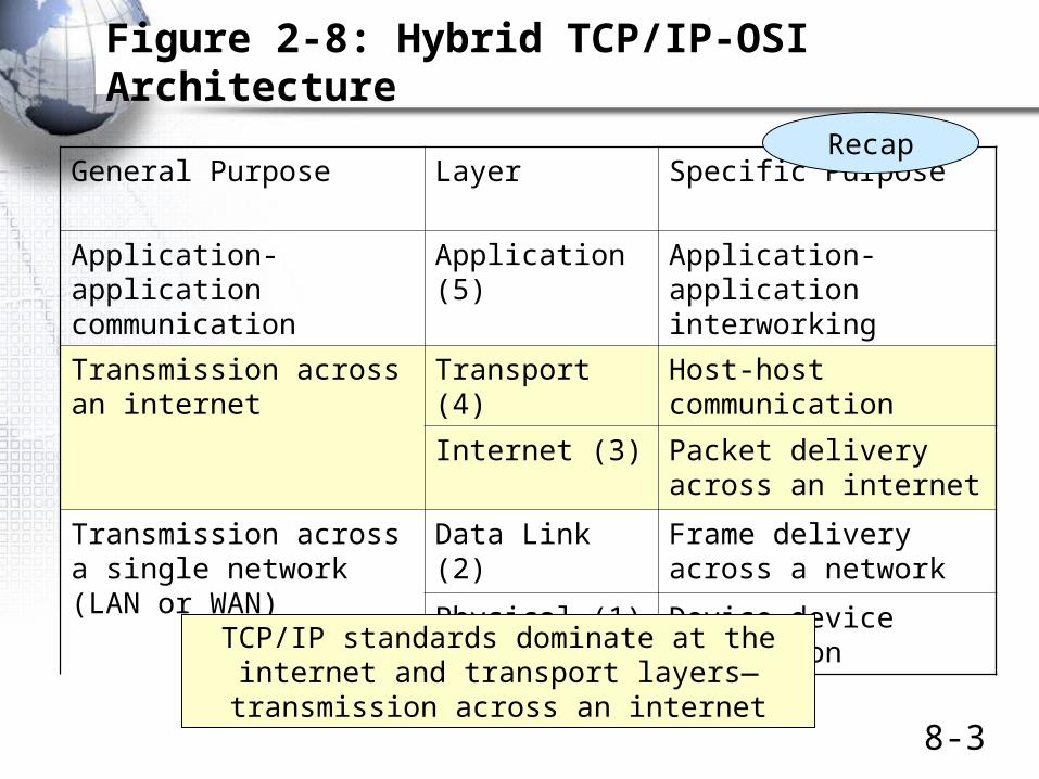
General Purpose Layer Specific Purpose
Application-application communication
Application (5) Application-application interworking
Transmission across an internet
Transport (4) Host-host communication
Internet (3) Packet delivery across an internet
Transmission across a single network (LAN or WAN)
Data Link (2) Frame delivery across a network
Physical (1) Device-device connection
Recap
TCP/IP standards dominate at theinternet and transport layers—transmission across an internet

8-4
Figure 2-11: Internet and Transport Layer, Cont.
Transport Layerend-to-end (host-to-host)
TCP is connection-oriented, reliableUDP is connectionless and unreliable
Internet Layer(usually IP)
hop-by-hop (host-router or router-router)connectionless, unreliable
Router 1 Router 2 Router 3
Client PCServer
Recap

8-5
Frames and Packets
• Messages at the data link layer are called frames
• Messages at the internet layer are called packets
• Within a single network, packets are encapsulated in the data fields of frames
FrameHeader
Packet(Data Field)
FrameTrailer
Recap

8-6
Frames and Packets
• In an internet with hosts separated by N networks, there will be:
– 2 hosts
– One packet (going all the way between hosts)
• One route (between the two hosts)
– N frames (one in each network)
Recap

8-7
Figure 2-21: Combining Horizontal and Vertical Communication
Int
App
DL
Trans
Phy
Int
Trans
IntInt
SourceHost
DestinationHost
Switch1
Switch2
Router1
Switch3
Router2
Transmission Control Protocol (TCP)Or User Datagram Protocol (UDP)
Internet Protocol(IP)
Recap
IP

8-8
Figure 8-1: Major TCP/IP Standards
5 ApplicationUser Applications
HTTP SMTPMany
OthersDNS
RoutingProtocols
ManyOthers
Supervisory Applications
TCP UDP4 Transport
IP3 InternetMPLS
ARP
None: Use OSI Standards2 Data Link
None: Use OSI Standards1 PhysicalInternetworking is done at the internet and transport layers.
There are only a few standards at these layers.We will look at the shaded protocols in this chapter.
ICMP

8-9
Figure 8-1: Major TCP/IP Standards, Continued
5 ApplicationUser Applications
HTTP SMTPMany
OthersDNS
RoutingProtocols
ManyOthers
Supervisory Applications
TCP UDP4 Transport
IP3 Internet ICMP ARP
None: Use OSI Standards2 Data Link
None: Use OSI Standards1 Physical At the application layer, there areuser applications and supervisory applications.
We will look at two TCP/IP application layer supervisory applications in this chapter.

• Page 348
• Test Your understanding
• 1

IP Addresses
32-Bit Strings
Dotted Decimal Notation for Human Reading(e.g., 128.171.17.13)

8-12
Figure 8-3: Hierarchical IP Address
128.171.17.13
Network Part (not always 16 bits)
Subnet Part (not always 8 bits)
Host Part (not always 8 bits)
Total always is 32 bits
UH Network (128.171)
CBA Subnet (17)Host 13
The Internet
Figure 8-3: Hierarchical IP Address
IP addresses are notsimple 32-bit numbers.
They usually have 3 parts.
Consider the example128.171.17.13

8-13
Hierarchical Addressing
• Hierarchical Addressing Brings Simplicity
– Phone System
• Country code-area code-exchange-subscriber number
• 01-808-555-9889
– Long-distance switches near the top of the hierarchy only have to deal with country codes and area codes to set up circuits
– Similarly, core Internet routers only have to consider network or network and subnet parts of packets

Router Operation

8-15
Figure 8-4: Border Router, Intrernal Router, Networks, and SubnetsFigure 8-4: Border Router, Internal Router, Networks, and Subnets
ISP Network60.x.x.x
Subnet 192.168.2.x
Subnet 192.168.3.x
Subnet192.168.1.xInternal
Router
BorderRouter
CorporateNetwork
192.168.x.x
Border routers connect different Internet networks(In this case, 192.168.x.x and 60.x.x.x).
An “x” indicates anything.

8-16
Figure 8-4: Border Router, Internal Router, Networks, and SubnetsFigure 8-4: Border Router, Internal Router, Networks, and Subnets
ISP Network60.x.x.x
Subnet 192.168.2.x
Subnet 192.168.3.x
Subnet192.168.1.xInternal
Router
BorderRouter
CorporateNetwork
192.168.x.x
Internal routers connect different subnets in a network.In this case, the three subnets are boxed in red:
192.168.1.x, 192.168.2.x, and 192.168.3.x.
8-17
Figure 8-5: Multiprotocol Routing
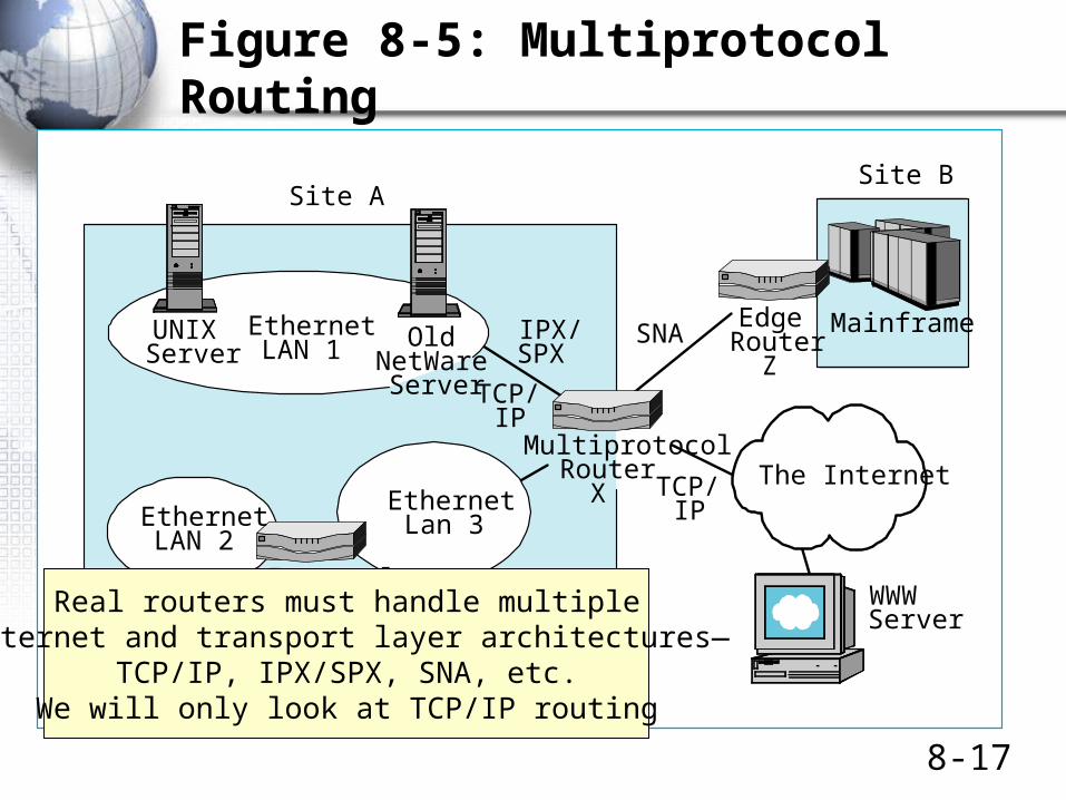
MultiprotocolRouter
X TCP/IP
TCP/IP
IPX/SPX
SNA
WWWServer
EdgeRouter
Z
Site ASite B
Mainframe
InternalRouter
Y
EthernetLAN 1
EthernetLAN 2
EthernetLan 3
The Internet
OldNetWareServer
UNIXServer
Figure 8-5: Multiprotocol Routing
Real routers must handle multipleinternet and transport layer architectures—
TCP/IP, IPX/SPX, SNA, etc.We will only look at TCP/IP routing

• Page 351
• Test Your understanding
• 2

8-19
Figure 8-6: Ethernet Switching Versus IP Routing
A1-44-D5-1F-AA-4CSwitch 1, Port 2 B2-CD-13-5B-E4-65
Switch 1, Port 7
Port 7 on Switch 2to Port 4 on Switch 3
Port 5 on Switch 1to Port 3 on Switch 2
Switch2
Switch1
Switching Table Switch 1
Port Station2 A1-44-D5-1F-AA-4C7 B2-CD-13-5B-E4-655 C3-2D-55-3B-A9-4F5 D4-47-55-C4-B6-9F5 E5-BB-47-21-D3-56
Ethernet Switching
Destination address is E5-BB-47-21-D3-56.Ethernet switches are arranged in a hierarchy.
So there is only one possible path between hosts.So only one row can match an Ethernet address.
Finding this row is very simple and fast.So Ethernet switching is inexpensive per frame handled.
One Correct Row

8-20
Figure 8-6: Ethernet Switching Versus IP Routing
Network60.x.x.x
Packet to 60.3.47.129
Router B
Router C
Interface1
Interface2
Network60.x.x.x
IP Routing
Network60.3.x.x
Route
123456
IP AddressRange
60.3.x.x128.171.x.x60.3.47.x10.5.3.x
128.171.17.x10.4.3.x
Metric
928622
Router A
Routing Table for Router A
Host60.3.45.129
Next-HopRouter
BBCB
LocalC
Routing
Matches
Host60.3.47.x
Because of multiple alternative routes in router meshes,routers may have several rows that match an IP address.
Routers must find All matches and then select the BEST ONE.This is slow and therefore expensive compared to switching.

8-21
Figure 8-7: The Routing Process
• Routing
– Processing an individual packet and passing it on its way is called routing
• Router ports are called interfaces
• Packet arrives in one interface
• The router sends the packetout another interface

8-22
Figure 8-7: The Routing Process
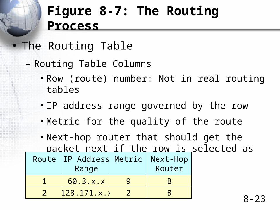
• The Routing Table
– Each router has a routing table that it uses to make routing decisions
– Routing Table Rows
• Each row represents a route for a RANGE of IP addresses—often a network or subnet
• All packets with addresses in this range are routed according to that row
RouteIP Address Range
Governed by the routeMetric
Next-HopRouter
1 60.3.x.x 9 B
8-23
Figure 8-7: The Routing Process
• The Routing Table
– Routing Table Columns
• Row (route) number: Not in real routing tables
• IP address range governed by the row
• Metric for the quality of the route
• Next-hop router that should get the packet next if the row is selected as the best match
Route IP AddressRange
Metric Next-HopRouter
1 60.3.x.x 9 B
2 128.171.x.x 2 B

8-24
Figure 8-7: The Routing Process
• A Routing Decision
– The router looks at the destination IP address in an arriving packet (in this case, 60.3.47.12).
– 1. The router determines which rows match (have an IP address range containing the packet’s destination IP address)
• The router must check ALL rows for possible matches
Route IP AddressRange
Metric Next-HopRouter
1 60.3.x.x 9 B
2 128.171.x.x 2 B
Arriving Packet60.3.47.12
Match
No Match

8-25
Figure 8-7: The Routing Process
• A Routing Decision
– 2. After finding all matches, the router then determines the BEST-MATCH row
• 2A. Selects the row with the LONGEST MATCH– 60.3.x.x has 16 bits of match– 60.3.47.x has 24 bits of match so is a better match
• 2B. If two or more rows tie for the longest match, router uses the METRIC column value
– If cost, lowest metric value is best– If speed, highest metric value is best– Etc.
8-26
Figure 8-7: The Routing Process
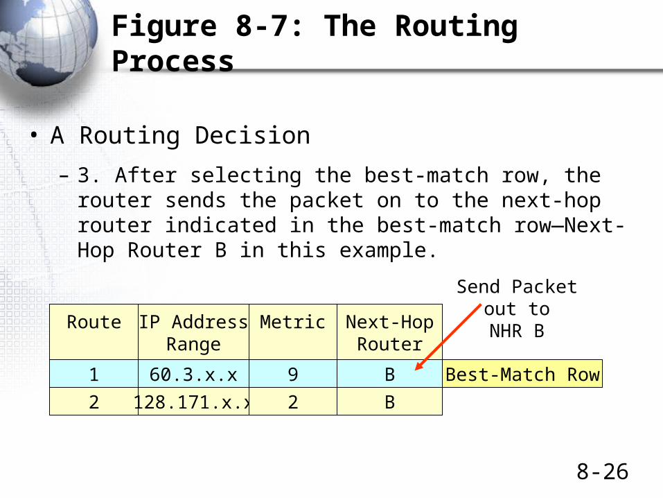
• A Routing Decision
– 3. After selecting the best-match row, the router sends the packet on to the next-hop router indicated in the best-match row—Next-Hop Router B in this example.
Route IP AddressRange
Metric Next-HopRouter
1 60.3.x.x 9 B
2 128.171.x.x 2 B
Best-Match Row
Send Packetout to
NHR B

A More Detailed Look at Routing Decisions
Box

8-28
Figure 8-8: Detailed Row-Matching Algorithm
• Routing Table
IP Address Range
Row Destination Mask … … …
1 10.7.3.0 255.255.255.0 … … …
2 … … … … …
3 … … … … …
Box
Actually, the table does not really have an “IP Address Range” column.Instead, it has two columns to indicate the IP address range:
Destination (an IP address) and a mask

8-29
Figure 8-8: Detailed Row-Matching Algorithm
• 1. Basic Rule of Masking
– Information Bit 1 0 1 0
– Mask Bit 1 1 0 0
– Result 1 0 0 0
• Where mask bits are one, the result gives the original IP address bits
• Where mask bits are zero, the result contains zeros
Box

8-30
Figure 8-8: Detailed Row-Matching Algorithm
• 2. Example
– Address (partial) 10101010 11001110
– Mask 11111000 00000000
– Result 10101000 00000000
Box

8-31
Figure 8-8: Detailed Row-Matching Algorithm
• 3. Common 8-bit Segment Values in Dotted Decimal Notation– Segment Decimal Value
00000000 0
11111111 255
• 4. Example– 255.255.255.0 is 24 ones followed by 8 zero
– 255.255.255.0 is also called /24 in “prefix notation”
Box

8-32
Figure 8-8: Detailed Row-Matching Algorithm
• Example 1: A Destination IP Address that is in the Range
• Destination IP Address of Arriving Packet 10.7.3.47
• Apply the Mask 255.255.255.0
• Result of Masking 10.7.3.0
• Destination Value 10.7.3.0
• Does Destination Value Match the Masking Result? Yes
• Conclusion Row 1 is a
match.
Row Destination Mask … … …
1 10.7.3.0 255.255.255.0 … … …
Box

8-33
Figure 8-8: Detailed Row-Matching Algorithm
• Example 2: A Destination IP Address that is NOT in the Range
• Destination IP Address of Arriving Packet 10.7.5.47
• Apply the Mask 255.255.255.0
• Result of Masking 10.7.5.0
• Destination Value 10.7.3.0
• Does Destination Value Match the Masking Result? No
• Conclusion Row 1 is NOT a
match.
Row Destination Mask … … …
1 10.7.3.0 255.255.255.0 … … …
Box

8-34
Figure 8-9: Interface and Next-Hop Router
• Switches
– A switch port connects directly to a single computer or another switch
– Sending the frame out a port automatically gets it to the correct destination
Frame
Box

8-35
Figure 8-9: Interface and Next-Hop Router
• Routers
– Router ports (interfaces) connect to subnets, which have multiple hosts and that may have multiple routers
– The packet must be forwarded to a specific host or router on that subnet
Subneton RouterInterface
IPPacket
Next-HopRouter
Host
Host
Box
Next-HopRouter

8-36
Figure 8-9: Interface and Next-Hop Router
RouterForwardingPacket
Figure 8-9: Interface and Next-Hop Router
IP Subnet onInterface (Port) 5
PossibleNext-HopRouter
PossibleDestinationHost
Packet must be sent toa particular host orrouter
Router A Router B
Packet to Router B out Interface 5
PossibleNext-HopRouter
Router C
Box
Best-match row has both an interface (indicating a subnet)and also a next-hop router value to indicate a host or router on the subnet.
(Not just a Next Hop Router Column)
Interface (port) Next-Hop Router
Next-Hop Router

• Page 353
• Test Your understanding
• 3
• Page 354
• Test Your understanding
• 5
• Page 357
• Test Your understanding
• 6
• Page 358
• Test Your understanding
• 7

Dynamic Routing Protocols
Routing Table Information
Dynamic Routing Protocol
8-39
Figure 8-10: Dynamic Routing Protocols
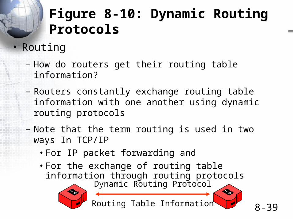
• Routing
– How do routers get their routing table information?
– Routers constantly exchange routing table information with one another using dynamic routing protocols
– Note that the term routing is used in two ways In TCP/IP
• For IP packet forwarding and
• For the exchange of routing table information through routing protocols
Routing Table Information
Dynamic Routing Protocol

• Page 364
• Test Your understanding
• 9

The Address Resolution Protocol (ARP)

8-42
Figure 8-12: Address Resolution Protocol (ARP)
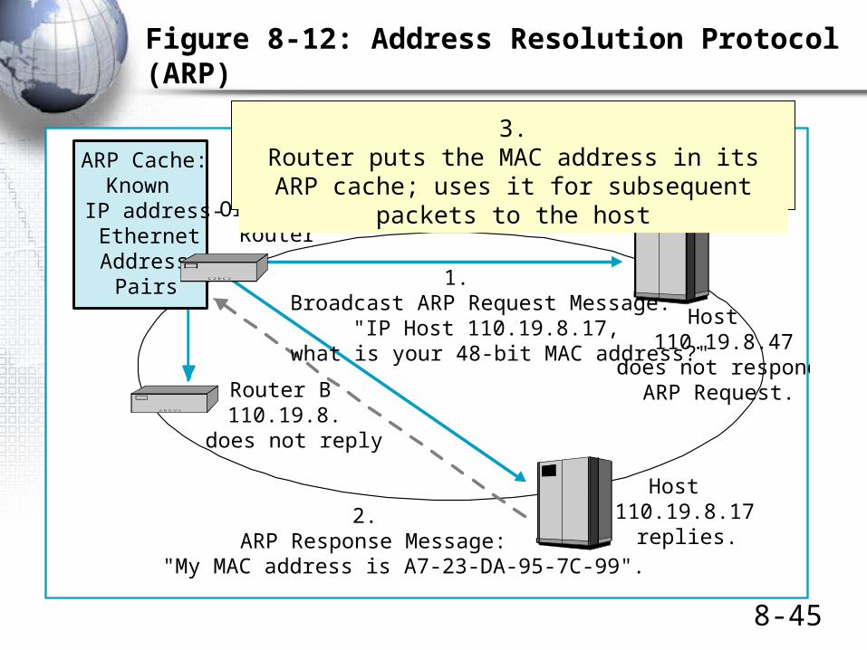
OriginatingRouter
Host110.19.8.47
does not respond toARP Request.
1.Broadcast ARP Request Message:
"IP Host 110.19.8.17,what is your 48-bit MAC address?"
Host110.19.8.17
replies.2.
ARP Response Message:"My MAC address is A7-23-DA-95-7C-99".
Figure 8-12: Address Resolution Protocol (ARP)
Router B110.19.8.
does not reply
ARP Cache:Known
IP address-EthernetAddress
Pairs
The Situation:The router wishes to pass the packet to the
destination host or to a next-hop router.The router knows the destination IP address of the target.
The router must learn the target’s MAC layer addressin order to be able to send the packet to the target in a frame.
The router uses the Address Resolution Protocol (ARP)
Packet
Frame

8-43
OriginatingRouter
Host110.19.8.47
does not respond toARP Request.
1.Broadcast ARP Request Message:
"IP Host 110.19.8.17,what is your 48-bit MAC address?"
Host110.19.8.17
replies.2.
ARP Response Message:"My MAC address is A7-23-DA-95-7C-99".
Figure 8-12: Address Resolution Protocol (ARP)
Router B110.19.8.
does not reply
ARP Cache:Known
IP address-EthernetAddress
Pairs
Figure 8-12: Address Resolution Protocol (ARP)
1: Router broadcasts ARP Request to all hosts and routers on the subnet.

8-44
OriginatingRouter
Host110.19.8.47
does not respond toARP Request.
1.Broadcast ARP Request Message:
"IP Host 110.19.8.17,what is your 48-bit MAC address?"
Host110.19.8.17
replies.2.
ARP Response Message:"My MAC address is A7-23-DA-95-7C-99".
Figure 8-12: Address Resolution Protocol (ARP)
Router B110.19.8.
does not reply
ARP Cache:Known
IP address-EthernetAddress
Pairs
Figure 8-12: Address Resolution Protocol (ARP)
This is theDestination host
2: ARP Reply sent by the host with the target IP address.
Other hosts ignore it.
8-45
OriginatingRouter
Host110.19.8.47
does not respond toARP Request.
1.Broadcast ARP Request Message:
"IP Host 110.19.8.17,what is your 48-bit MAC address?"
Host110.19.8.17
replies.2.
ARP Response Message:"My MAC address is A7-23-DA-95-7C-99".
Figure 8-12: Address Resolution Protocol (ARP)
Router B110.19.8.
does not reply
ARP Cache:Known
IP address-EthernetAddress
Pairs
Figure 8-12: Address Resolution Protocol (ARP)
3.Router puts the MAC address in its ARP cache;
uses it for subsequent packets to the host
• Page 367
• Test Your understanding
• 11

The Domain Name System (DNS)

8-48
Figure 8-14: Domain Name System (DNS) Hierarchy
(root)
cnn.commicrosoft.comhawaii.edu
.com .uk.ie.edu .net
Top-LevelDomainNames
Second-LevelDomainNames
Subnet Namecba.hawaii.edu
voyager.cba.hawaii.edu ntl.cba.hawaii.eduHost Names
Figure 8-14: Domain Name System (DNS) Hierarchy
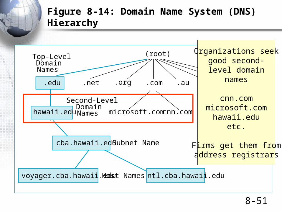
.nl.org .auA domain is a group of resources
under the control of an organization.
The domain name system is ageneral system for managing names.
It is a hierarchical naming system.
Queries to a DNS server can getInformation about a domain.

8-49
Figure 8-14: Domain Name System (DNS) Hierarchy
(root)
cnn.commicrosoft.comhawaii.edu
.com .uk.ie.edu .net
Top-LevelDomainNames
Second-LevelDomainNames
Subnet Namecba.hawaii.edu
voyager.cba.hawaii.edu ntl.cba.hawaii.eduHost Names
Figure 8-14: Domain Name System (DNS) Hierarchy
.nl.org .au
The highest level (0) is called the root.There are 13 DNS Root Servers.They point to lower-level servers.

8-50
Figure 8-14: Domain Name System (DNS) Hierarchy
(root)
cnn.commicrosoft.comhawaii.edu
.com .uk.ie.edu .net
Top-LevelDomainNames
Second-LevelDomainNames
Subnet Namecba.hawaii.edu
voyager.cba.hawaii.edu ntl.cba.hawaii.eduHost Names
Figure 8-14: Domain Name System (DNS) Hierarchy
.nl.org .au
Top-level domains aregeneric TLDs (.com, .net., .org, etc.) or
country TLDs (.ca, .uk, .ie, etc.)
8-51
Figure 8-14: Domain Name System (DNS) Hierarchy
(root)
cnn.commicrosoft.comhawaii.edu
.com .uk.ie.edu .net
Top-LevelDomainNames
Second-LevelDomainNames
Subnet Namecba.hawaii.edu
voyager.cba.hawaii.edu ntl.cba.hawaii.eduHost Names
Figure 8-14: Domain Name System (DNS) Hierarchy
.nl.org .au
Organizations seekgood second-level domain
names
cnn.commicrosoft.com
hawaii.eduetc.
Firms get them fromaddress registrars

8-52
Figure 8-14: Domain Name System (DNS) Hierarchy
(root)
cnn.commicrosoft.comhawaii.edu
.com .uk.ie.edu .net
Top-LevelDomainNames
Second-LevelDomainNames
Subnet Namecba.hawaii.edu
voyager.cba.hawaii.edu ntl.cba.hawaii.eduHost Names
Figure 8-14: Domain Name System (DNS) Hierarchy
.nl.org .au
Host names are the bottomof the DNS hierarchy.
A DNS request for a host namewill return its IP address.

• Page 370
• Test Your understanding
• 13
Dynamic Host Configuration Protocol (DHCP)
From Chapter 1

8-55
Figure 8-16: Dynamic Host Configuration Protocol (DHCP)
• DHCP Gives Each Client PC at Boot-Up:
– A temporary IP Address (we saw this in Chapter 1)
– A subnet mask
– The IP addresses of local DNS servers
• Better Than Manual Configuration
– If subnet mask or DNS IP addresses change, only the DHCP server has to be updated manually
– Client PCs are automatically updated when they next boot up

• Page 372
• Test Your understanding
• 15

The Internet Protocol (IP)
Versions 4 and 6

8-58
Figure 8-17: IPv4 and IPv6 Packets
IP Version 4 Packet
Version(4 bits)Valueis 4
(0100)
HeaderLength(4 bits)
Flags(3 bits)
Time to Live(8 bits)
Header Checksum(16 bits)
Diff-Serv(8 bits)
Total Length(16 bits)
Length in octets
Bit 0 Bit 31
Identification (16 bits)Unique value in each original
IP packet
Fragment Offset (13 bits)Octets from start of
original IP fragment’sdata field
Protocol (8 bits)1=ICMP, 6=TCP,
17=UDP
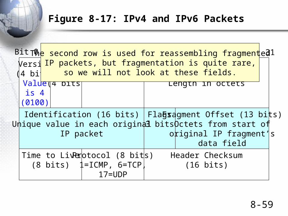
IPv4 is the dominant version of IP today.The version number in its header is 4 (0100).
The header length and total length field tell the size of the packet.
The Diff-Serv field can be used for quality of service labeling.(But MPLS is being used instead by most carriers)
8-59
Figure 8-17: IPv4 and IPv6 Packets
IP Version 4 Packet
Version(4 bits)Valueis 4
(0100)
HeaderLength(4 bits)
Flags(3 bits)
Time to Live(8 bits)
Header Checksum(16 bits)
Diff-Serv(8 bits)
Total Length(16 bits)
Length in octets
Bit 0 Bit 31
Identification (16 bits)Unique value in each original
IP packet
Fragment Offset (13 bits)Octets from start of
original IP fragment’sdata field
Protocol (8 bits)1=ICMP, 6=TCP,
17=UDP
The second row is used for reassembling fragmentedIP packets, but fragmentation is quite rare,
so we will not look at these fields.

8-60
Figure 8-17: IPv4 and IPv6 Packets
IP Version 4 Packet
Version(4 bits)Valueis 4
(0100)
HeaderLength(4 bits)
Flags(3 bits)
Time to Live(8 bits)
Header Checksum(16 bits)
Diff-Serv(8 bits)
Total Length(16 bits)
Length in octets
Bit 0 Bit 31
Identification (16 bits)Unique value in each original
IP packet
Fragment Offset (13 bits)Octets from start of
original IP fragment’sdata field
Protocol (8 bits)1=ICMP, 6=TCP,
17=UDP
The sender sets the time-to-live value (usually 64 to 128).Each router along the way decreases the value by one.
A router decreasing the value to zero discards the packet.It may send an ICMP error message.
The protocol field describes the message in the data field(1=ICMP, 2=TCP, 3=UDP, etc.)
The header checksum is used to find errors in the header.If a packet has an error, the router drops it.
There is no retransmission at the internet layer,so the internet layer is still unreliable.
8-61
Figure 8-17: IPv4 and IPv6 Packets
IP Version 4 Packet
Source IP Address (32 bits)
Bit 0 Bit 31
Destination IP Address (32 bits)
PaddingOptions (if any)
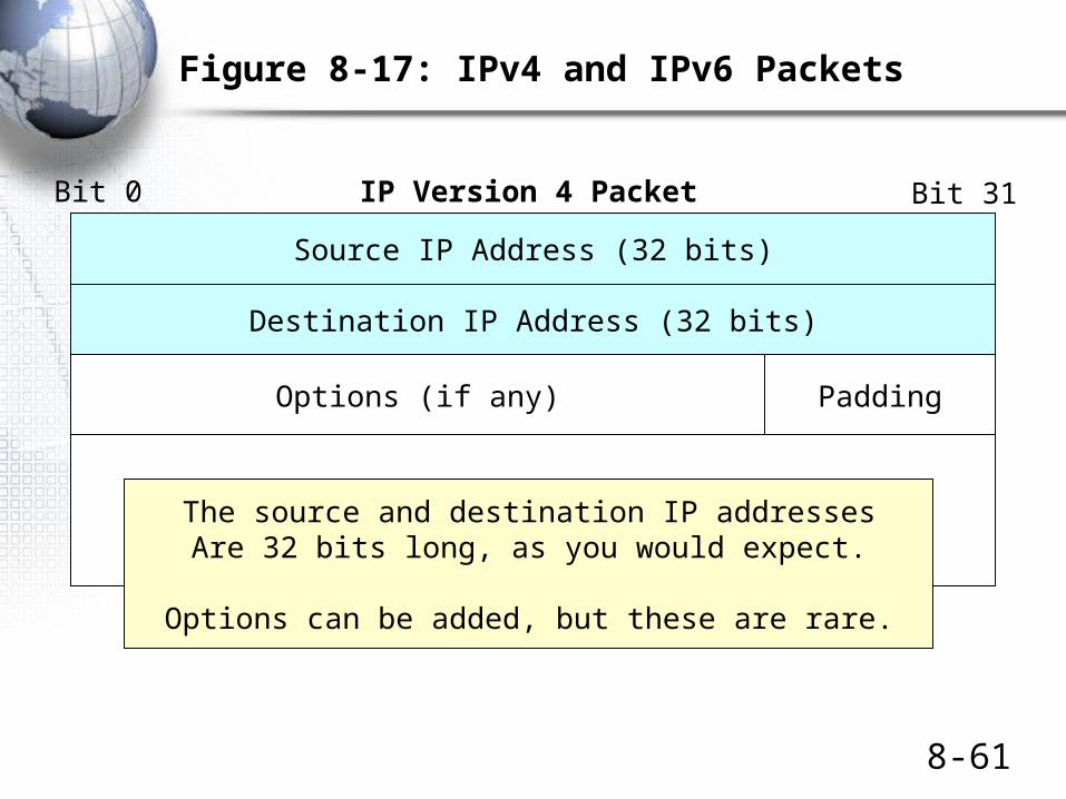
Data FieldThe source and destination IP addressesAre 32 bits long, as you would expect.
Options can be added, but these are rare.

8-62
Figure 8-17: IPv4 and IPv6 Packets
IP Version 6 Packet
Source IP Address (128 bits)
Bit 0 Bit 31
Hop Limit(8 bits)
Next Header(8 bits) Nameof next header
Payload Length(16 bits)
Version(4 bits)Valueis 6
(0110)
Diff-Serv(8 bits)
Flow Label (20 bits)Marks a packet as part of a specific flow
Destination IP Address (128 bits)
Next Header or Payload (Data Field)
IP Version 6 is the emergingversion of the Internet protocol.
Has 128 bit addresses foran almost unlimited number of IP addresses.
Needed because of rapid growth in Asia.
Also needed because of the explodingnumber of mobile devices

• Page 375
• Test Your understanding
• 16
• 17

The Transmission Control Protocol (TCP)

8-65
Figure 8-18: TCP Segment and UDP Datagram
TCP Segment
Window Size(16 bits)
Bit 0 Bit 31
Destination Port Number (16 bits)Source Port Number (16 bits)
Sequence Number (32 bits)
Acknowledgment Number (32 bits)
Urgent Pointer (16 bits)TCP Checksum (16 bits)
HeaderLength(4 bits)
Reserved(6 bits)
Flag Fields(6 bits)
Flag fields are one-bit fields. They include SYN, ACK, FIN,and RST.
The source and destination port numbersspecify a particular application on the
source and destination multitasking computers(Discussed later)
Sequence numbers are 32 bits long.So are acknowledgment numbers.

8-66
Figure 8-18: TCP Segment and UDP Datagram
TCP Segment
Window Size(16 bits)
Bit 0 Bit 31
Destination Port Number (16 bits)Source Port Number (16 bits)
Sequence Number (32 bits)
Acknowledgment Number (32 bits)
Urgent Pointer (16 bits)TCP Checksum (16 bits)
HeaderLength(4 bits)
Reserved(6 bits)
Flag Fields(6 bits)
Flags are one-bit fields.If a flag’s value is 1, it is “set”.
If a flag’s value is 0, it is “not set.”TCP has six flags
If the TCP Checksum field’s value is correct,The receiving process sends back an acknowledgment.

8-67
Figure 8-18: TCP Segment and UDP Datagram
TCP Segment
Window Size(16 bits)
Bit 0 Bit 31
Destination Port Number (16 bits)Source Port Number (16 bits)
Sequence Number (32 bits)
Acknowledgment Number (32 bits)
Urgent Pointer (16 bits)TCP Checksum (16 bits)
HeaderLength(4 bits)
Reserved(6 bits)
Flag Fields(6 bits)
For flow control (to tell the other party to slow down),The sender places a small value in the Window Size field.
If the Window Size is small, the receiver will have to stop transmittingafter a few more segments (unless it gets a new acknowledgment
extending the number of segments it may send.)

8-68
Figure 8-18: TCP Segment and UDP Datagram
TCP SegmentBit 0 Bit 31
PaddingOptions (if any)
Data Field
TCP segment headers can end with options.Unlike IPv4 options,
TCP options are very common.
If an option does not end at a 32-bit boundary,padding must be added.

The User Datagram Protocol (UDP)

8-70
Figure 8-18: TCP Segment and UDP Datagram
UDP DatagramBit 0 Bit 31
Source Port Number (16 bits) Destination Port Number (16 bits)
UDP Length (16 bits) UDP Checksum (16 bits)
Data Field
UDP messages (datagrams) are very simple.Like TCP, UDP has 16-bit port numbers.
The UDP length field allows variable-length application messages.If the UDP checksum is correct, there is no acknowledgment.
If the UDP checksum is incorrect, the UDP datagram is dropped.

8-71
Figure 8-19: TCP Connection Openings and Closings
• TCP is a connection-oriented protocol
– Each connection has a formal opening process
– Each connection has a formal closing process
– During a connection, each TCP segment is acknowledged
• (Of course, pure acknowledgments are not acknowledged)

8-72
Figure 8-19: TCP Connection Openings and Closings
SYN
SYN/ACK
ACK
Normal Three-Way Opening
A SYN segment is a segment in which the SYN bit is set.One side sends a SYN segment requesting an opening.The other side sends a SYN/acknowledgment segment.
Originating side acknowledges the SYN/ACK.

Figure 8.16: Transmission Control Protocol (TCP) Time Diagram
张三和李四之间要通过 Internet 互相通讯,由李四提供信息给张三访问。在真正建立通信通道之前,必须由 TCP 进行握手确认后才能建立可靠的网络连接。握手过程如下:1. 首先由张三向李四发出访问请求。如图中说述:张三对李四说“我可以访问你的网站吗?”这个请求在 TCP 协议的表达是张三向李四发出一个使用 TCP 协议的数据包,这个数据包带有张三同步标志位( SYN位)。所以这个数据包称为张三的 SYN 包;2. 当李四接收到张三的请求之后,如果他认为张三可以访问自己的信息,就会给张三一个明确的回应并询问“你可以访问我的网站的,听见吗?”这个回应会表现为 TCP 数据包带有李四的同步标志位( SYN )和对张三的回应标志位( ACK )。所以这个回应数据包被称为 SYN/ACK 包;3. 之后张三收到了李四的回应和询问,就对李四发出回答:“我听到了”。于是双发就建立起 TCP 可靠连接的数据通道了。这个张三对李四询问的回应带有 TCP 的回应标志位( ACK )。所以被称为 ACK 包。
8-74
Figure 8-19: TCP Connection Openings and Closings
FIN
ACK
FIN
ACK
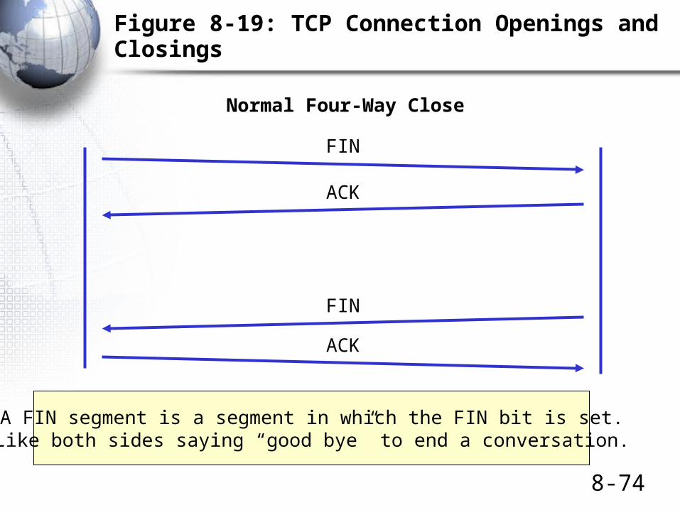
Normal Four-Way Close
A FIN segment is a segment in which the FIN bit is set.Like both sides saying “good bye” to end a conversation.

8-75
Figure 8-19: TCP Connection Openings and Closings
RST
Abrupt Reset
An RST segment is a segment in which the RST bit is set.A single RST segment breaks a connection.
Like hanging up during a phone call.There is no acknowledgment.

• Page 376
• Test Your understanding
• 18
• Page 379
• Test Your understanding
• 19

Port Numbers and Sockets in TCP and UDP

8-78
TCP and UDP Port Numbers
• Computers are multitasking devices
– They run multiple applications at the same time
– On a server, a port number designates a specific applications
Server
HTTP WebserverApplication
SMTP E-MailApplications
Port 80 Port 25

8-79
TCP and UDP Port Numbers
• Major Applications Have Well-Known Port Numbers– 0 to 1023 for both TCP and UDP– HTTP is TCP Port 80– SMTP is TCP Port 25
Server
HTTP WebserverApplication
SMTP E-MailApplications
Port 80 Port 25

8-80
TCP and UDP Port Numbers
• Clients Use Ephemeral Port Numbers– 1024 to 4999 for Windows Client PCs– A client has a separate port number for each connection
to a program on a server
Client
Port 4400Port 3270
WebserverApplication
on Webserver
E-MailApplication
on MailServer

8-81
Figure 8-20: Use of TCP (and UDP) Port Numbers
Client 60.171.18.22
Webserver1.33.17.13
Port 80
SMTP Server123.30.17.120
Port 25
A socket is anIP address, a colon, and a port number.
1.33.17.3:80123.30.17.120:25
128.171.17.13:2849
It represents a specific application (Port number)on a specific server (IP address)
Or a specific connection on a client.
Client PC128.171.17.13
Port 2849

8-82
Figure 8-20: Use of TCP (and UDP) Port Numbers
Client60.171.18.22
Webserver1.33.17.13
Port 80
Source: 60.171.18.22:2707Destination: 1.33.17.13:80
SMTP Server123.30.17.120
Port 25
This shows sockets for a clientpacket sent to a webserver application
on a webserver

8-83
Figure 8-20: Use of TCP (and UDP) Port Numbers
Client60.171.18.22
Webserver1.33.17.13
Port 80
Source: 60.171.18.22:2707Destination: 1.33.17.13:80
Source: 1.33.17.13:80Destination: 60.171.18.22:2707
SMTP Server123.30.17.120
Port 25
Sockets intwo-way
transmission

8-84
Figure 8-20: Use of TCP (and UDP) Port Numbers
Client60.171.18.22
Webserver1.33.17.13
Port 80
Source: 60.171.18.22:2707Destination: 1.33.17.13:80
Source: 1.33.17.13:80Destination: 60.171.18.22:2707
Source: 60.171.18.22:4400Destination: 123.30.17.120:25
SMTP Server123.30.17.120
Port 25Clients use a different ephemeralport number for different connections

• Page 381
• Test Your understanding
• 20-22
• Page 382
• Test Your understanding
• 23

Layer 3 Switches

8-87
Figure 8-21: Layer 3 Switches and Routers in Site Networks
Router
Ethernet WorkgroupSwitch
ToOtherSites
Layer 3Switch
L3
L3
Layer 3 switches arerouters.
Layer 3 switches arefaster and cheaper tobuy than traditionalrouters.
However, they areusually limited infunctionality.
They also areexpensive to manage.
They are typicallyused between
Figure 8-21: Layer 3 Switches and Routers in Site Internets
Ethernet WorkgroupSwitch
Layer 3Switch
Usually too expensive to replace workgroup switches.Usually too limited in functionality to replace border routers.
Replaces core switches in the middle.

• Page 384
• Test Your understanding
• 24-25

IP地址的分类
A 类、 B 类、 C 类地址 见本书 Module A 413 页和《电子商务原理》 69 页

IP Address Classes
• How large is the network part in an IP address?
• Today we use network masks to tell
• Originally, IP had address classes with fixed numbers of bits in the network part
– Class A: 8 bits (24 bits in local part)
– Class B: 16 bits (16 bits in local part)
– Class C: 24 bits (8 bits in local part)

Class A IP Address
• IP address begins with 0
• 7 remaining bits in network part
– Only 128 possible Class A networks
• 24 bits in local part
– Over 16 million hosts per Class A network!
• All Class A network parts are assigned or reserved
• 1.x.y.z ~ 127.x.y.z

Class B IP Address
• IP address begins with 10 (1st zero in 2nd position)
• 14 remaining bits in network part– Over 16,000 possible Class B networks
• 16 bits in local part– Over 65,000 possible hosts
• A good trade-off between number of networks and hosts per network
• Most have been assigned
• 128.x.y.z ~ 191.x.y.z
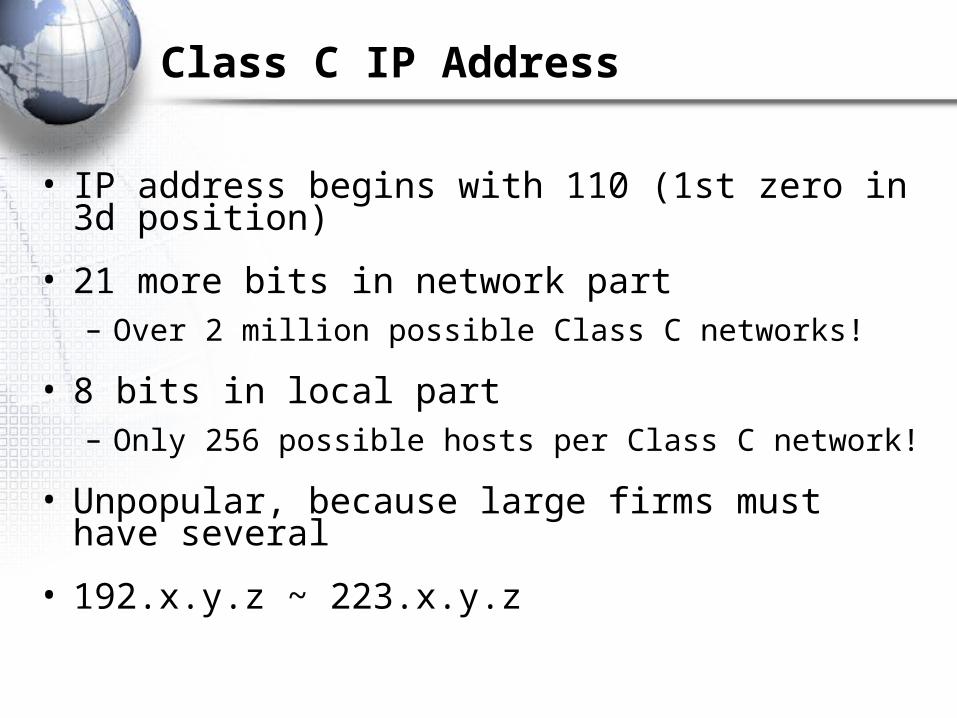
Class C IP Address
• IP address begins with 110 (1st zero in 3d position)
• 21 more bits in network part– Over 2 million possible Class C networks!
• 8 bits in local part– Only 256 possible hosts per Class C network!
• Unpopular, because large firms must have several
• 192.x.y.z ~ 223.x.y.z

Class D IP Address
• IP address begins with 1110
• Used for multicasting, not defining networks
– Sending message to group of hosts
– Not just to one (unicasting)
– Not ALL hosts (broadcasting)
– Say to send a videoconference stream to a group of receivers

私有网络 IP地址
RFC1579 推荐了用于私有网络的各类地址:A 类地址: 10.0.0.0 ~ 10.255.255.255
00001010.xxxxxxxx.xxxxxxxx.xxxxxxxx (24bits)
B 类地址: 172.16.0.0 ~ 172.31.255.255
10101100.0001xxxx.xxxxxxxx.xxxxxxxx (20bits)
C 类地址: 192.168.0.0 ~ 192.168.255.255
11000000.10101000.xxxxxxxx.xxxxxxxx (16bits)

Topics Covered
8-97
Topics Covered
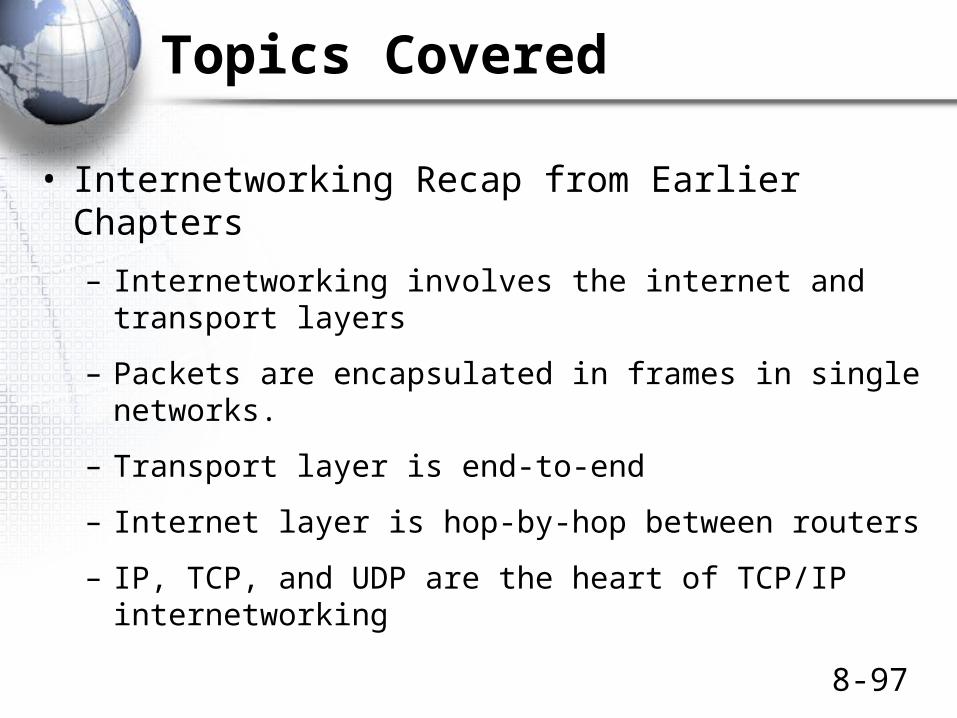
• Internetworking Recap from Earlier Chapters
– Internetworking involves the internet and transport layers
– Packets are encapsulated in frames in single networks.
– Transport layer is end-to-end
– Internet layer is hop-by-hop between routers
– IP, TCP, and UDP are the heart of TCP/IP internetworking
8-98
Topics Covered
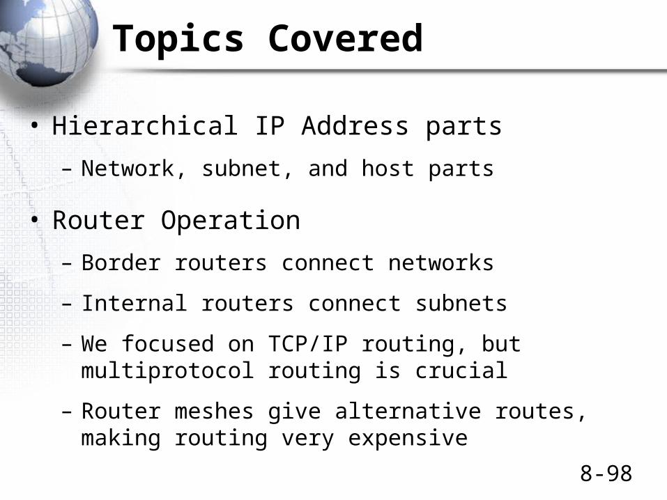
• Hierarchical IP Address parts
– Network, subnet, and host parts
• Router Operation
– Border routers connect networks
– Internal routers connect subnets
– We focused on TCP/IP routing, but multiprotocol routing is crucial
– Router meshes give alternative routes, making routing very expensive
8-99
Topics Covered
• Routing of Packets• Routing tables
• IP address range governed by a row—usually a route to a network or subnet
• Metric to help select best matches
• Next-hop router to be sent the packet next– Can be a local host on one of the router’s subnets
– Process
• Final all possible routes through row matching
• Select by length of match, then metric if tie
• Send out to next-hop router in the best-match row
8-100
Topics Covered
• Detailed Look at Routing Decisions
• IP address range– Destination– Mask– If the masked destination IP address in an arriving
packet matches the destination value, the row is a match
• Next-Hop Router– Interface– Next-hop router or destination host
Box

8-101
Topics Covered
• Dynamic Routing Protocols• Interior dynamic routing protocols within an
autonomous system– RIP, OSPF, EIGRP
• Exterior dynamic routing protocols between autonomous systems
– BGP
• Address Resolution Protocol
– Router knows the IP address of the next-hop router or destination host
– Must learn the data link layer address as well

8-102
Topics Covered
• Domain Name System (DNS)– General hierarchical naming system for the Internet

8-103
Topics Covered
• The Internet Protocol (IP)
– Detailed look at key fields
– Protocol field lists contents of the data field
– 32-bit IP addresses
– IPv4 is the current version
– IPv6 offers 128-bit IP addresses to allow many more IP addresses to serve the world

8-104
Topics Covered
• The Transmission Control Protocol (TCP)
– Sequence and acknowledgement numbers
– Flag fields that are set or not set
– Window size field allows flow control
– Options are common
– Three-way openings (SYN, SYN/ACK, and ACK)
– Four-way normal closings (FIN, ACK, FIN, ACK)
– One-way abrupt closing (RST)

8-105
Topics Covered
• The User Datagram Protocol (UDP)– Simple four-field header
• Port Numbers and Sockets in TCP and UDP– Applications get well-known port numbers on servers
– Connections get ephemeral port numbers on clients
– Socket is an IP address, a colon, and a port number
– This designates a specific application (or connection) on a specific server (or client)
• Layer 3 Switches– Fast, inexpensive, and limited routers

• 考试时间地点 :
– 地点: H6106 室– 时间: 6 月 30 日 ( 周二 ) 下午: 13:00 – 15:00
• 答疑需要么?
• 思源楼 708 室
• 周一上午 9:00-11:30 ?

2009 年春网络课试卷题型
• 一、判断题
• 二、选择题
• 三、简答题(简短文字或画图说明)
• 四、问答题 + 计算题