tce i / ii central electronic in trailers...
TRANSCRIPT

772
8
Annex
TCE

78
8.1 Abbreviations usedABS = Anti-Lock Braking System
CAN = Controller Area Network
DA = Drawbar Trailer
EBS = Elektronic Brake System
ECAS = (Electronic Controlled Air Suspension System) Electronic Air Suspension
FN – Nominal Level
Gateway = Data distributor to the corresponding systems
HA = Rear Axle
H/S = Raise and Lower
KWP = Key Word Protocol
LA = Lift Axle
VA = Front Axle
EEPROM = Non-permanent Memory
FPIO = Freely programmable Inlets & OutletsUnit
IVTM = Integrated Vehicle Tire Monitor = Reifendrucküberwachung
RAH = Ramp approach help
RFS = Reverse Light
RGE = Running Gear Equipment = concerning driving safety, e.g. chassis, tires, steering, suspension
RGE I/O-Extension = Running Gear Equipment Inlets & Outlets Extension
SA = Semitrailer
Abbreviations8 TCE

79
8.2 Overview Drawing for CustomerPage
Cabling Diagram - TCE 841 801 840 0 81TCE Terminal Telematic System 841 801 841 0 / ... 846 0 82 / 83TCE Terminal Lighting 841 801 842 0 / ... 845 0 84 / 85
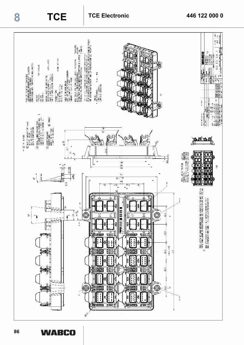
TCE Electronic 446 122 000 0 86
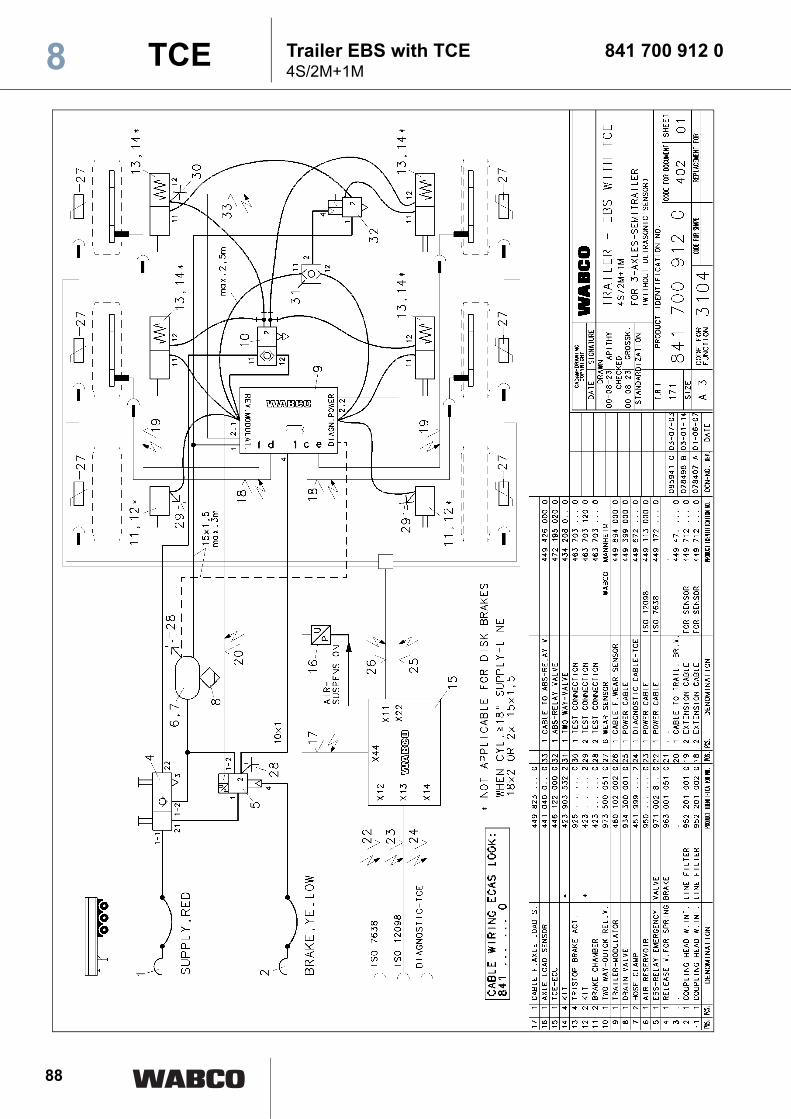
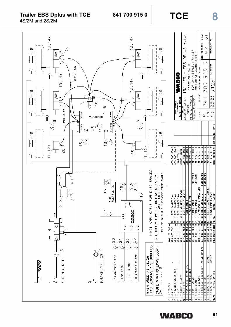
Braking systems 3 axle semitrailersTrailer EBS with TCE; 4S/2M and 2S/2M 841 700 910 0 87Trailer EBS with TCE; 4S/2M and 1M 841 700 912 0 88Trailer EBS with TCE; 4S/2M and 2S/2M 841 700 913 0 89Trailer EBS with TCE; 4S/2M and 2S/2M 841 700 914 0 90Trailer EBS with TCE; 4S/2M and 2S/2M 841 700 915 0 91Trailer EBS with TCE; 4S/2M and 2S/2M 841 700 916 0 92Trailer EBS Dplus with TCE; 4S/2M and 2S/2M 841 700 917 0 93Trailer EBS Dplus with TCE; 4S/2M and 2S/2M 841 700 918 0 94
TCE I / II ECAS Cabling DiagramSemitrailer 1 Height Sensor 841 801 847 0 95Semitrailer 1 Height Sensor with Lift Axle 841 801 848 0 96Semitrailer 1 Height Sensor with 2 Lift Axles 841 801 849 0 97Semitrailer 1 Height Sensor with Lift Axle Control 841 801 960 0 98Semitrailer 1 Height Sensor with Lift Axle 841 801 961 0 99Semitrailer 2 Height Sensors with 2 Lift Axles 841 801 962 0 100Semitrailer 2 Height sensors with axle load indication 841 801 963 0 101Semitrailer 1 Height Sensor with 2 Lift Axles 841 801 964 0 102Drawbar Trailer 2 Height sensors 841 801 965 0 103Semitrailer 1 Height Sensor, single circuit lift axle 841 801 966 0 104
CableTerminal X13 Supply to ISO 1185, ISO 3731, ISO 12098 (15-pin) 449 113 .. / 449 121 .. 105 / 106
449 123 .. / 449 311 .. 107 / 108Terminal X12 ABS / EBS supply to ISO 7638 (7-pin) 449 133 .. / 449 135 .. 109 / 110
449 172 .. / 449 272 .. 111 / 112449 333 .. / 449 335 .. 113 / 114
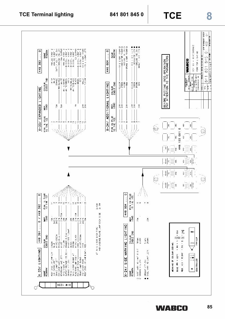
Terminal X32 Tire pressure control and Superstructure system CAN extensionCable for tire pressure monitoring 449 301 .. / 449 302 .. 115 / 116Cable for tire pressure monitoring 449 304 .. 117Terminal X23 Standard vehicle lightingCable for lighting carrier 449 391 .. / 449 392 .. 118 / 119Terminal X33 Extended lightingCable for additional lighting 449 393 000 0 120Terminal X22 Trailer EBSConnecting cable to EBS trailer modulator 449 394 000 0 121Connecting cable to EBS trailer modulator 449 399 000 0 122Terminal X 43 ECAS solenoid valveCable for solenoid valve 449 483 000 0 123Cable for solenoid valve with lift axle 449 484 000 0 124Cable for solenoid valve with lift axle 449 485 000 0 125Cable for solenoid valve with two lift axles 449 494 000 0 126Terminal X33 Extended lightingCable for tank vehicle 449 604 000 0 127
Overview Drawings for Customer 8TCE

80
Terminal X 41 ECAS control unitCable for two ECAS control units IRCU or RCU 449 634 000 0 128Cable for one ECAS control unit IRCU or RCU 449 635 000 0 129Cable for one ECAS control unit IRCU or RCU 449 654 000 0 131Cable for one ECAS control box 449 655 000 0 132Terminal X14 DiagnosisY-Diagnosis and warning light cable 449 644 000 0 130Cable with external round socket 449 672 000 0 133Terminal X31 Ultrasonic sensorsCable to the ultrasonic sensors 449 704 000 0 134Terminal X 42 Height sensor and battery boxCable for two height sensors and one battery box 449 804 000 0 135Cable for one height sensor and battery box 449 814 000 0 136Terminal X44 Pressure sensorCable for one pressure sensor 449 823 000 0 137Cable for two pressure sensors 449 824 000 0 138Terminal X11 Cable for brake lining wear sensorsBrake lining wear indicator for one axle (limit value indicator) 449 874 000 0 139Brake lining wear indicator for two axles (limit value indicator) 449 884 000 0 140Brake lining wear indicators for three axles (limit value indicator) 449 894 000 0 141Terminal X21 I/O type, extensionCable with open ends 449 902 000 0 142Cable with device socket 449 903 000 0 143Terminal X24 Side marking lampsCable to the side marking lamps (Pritax) 449 904 000 0 144
Components at the terminalX 11Wear indicator 12 480 036 145Wear indicator 12 480 038 146X 44Pressure sensor 441 040 007 0 147Pressure sensor 441 040 013 0 148Pressure sensor 441 040 015 0 149X 42Height sensor 441 050 012 0 150Battery box 446 156 090 0 / .. 094 0 154X 41ECAS control unit IRCU 446 056 202 0 151ECAS control box 446 156 000 0 153X 31Ultrasonic sensors 446 122 400 0 152X 14Diagnostic cable (6 m) toDiagnostic interface set 446 301 021 0 446 300 329 2 156X 43Lift axle control valve 463 084 010 0 1572. Lifting Axle solenoid valve 472 900 053 0 158ECAS solenoid valve 472 900 055 0 159ECAS solenoid valve 472 900 058 0 160ECAS solenoid valve with lift axle 472 905 111 0 161ECAS solenoid valve with lift axle or 472 905 114 0 1622. Lifting Axle solenoid valve (new) 472 880 001 0 163ECAS solenoid valve (new) 472 880 021 0 164ECAS solenoid valve (new) 472 880 030 0 165
Overview Drawings for Customer8 TCE

81
Wiring Diagram - TCE 841 801 840 0
2
8TCE

82
TCE Terminal Telematic System 841 801 841 08 TCE

83
TCE II - Terminal Telematic System 841 801 846 0
2
8TCE

84
TCE Terminal lighting 841 801 842 08 TCE
85
TCE Terminal lighting 841 801 845 0 8TCE
86
TCE Electronic 446 122 000 08 TCE

87
Trailer EBS with TCE 841 700 910 02S/2M and 4S/2M
TCE 8
2
88
Trailer EBS with TCE 841 700 912 04S/2M+1M
TCE8
2

89
Trailer EBS D with TCE 841 700 913 02S/2M and 4S/2M
TCE 8
2

90
Trailer EBS DO with TCE 841 700 914 04S/2M and 2S/2M
TCE8
2
91
Trailer EBS Dplus with TCE 841 700 915 04S/2M and 2S/2M
TCE 8
2
92
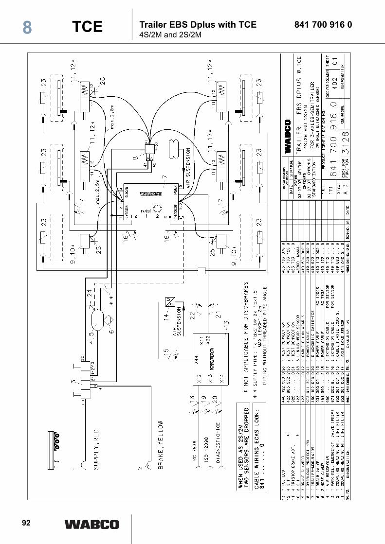
Trailer EBS Dplus with TCE 841 700 916 04S/2M and 2S/2M
TCE8
2

93
Trailer EBS Dplus with TCE 841 700 917 04S/2M and 2S/2M
TCE 8
2
94
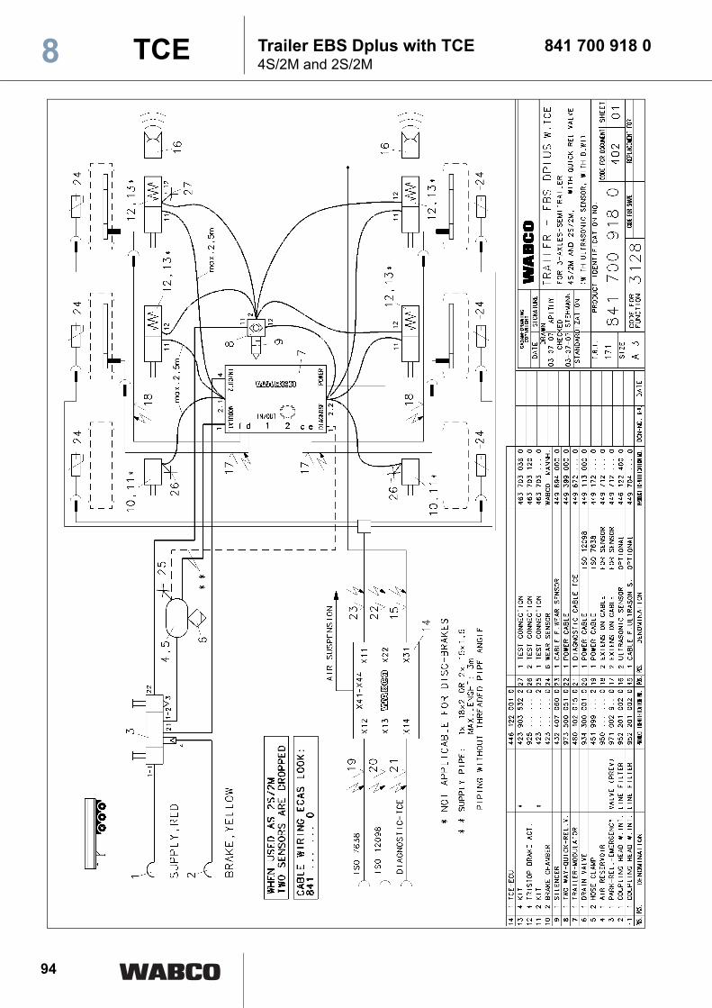
Trailer EBS Dplus with TCE 841 700 918 04S/2M and 2S/2M
TCE8
2
95
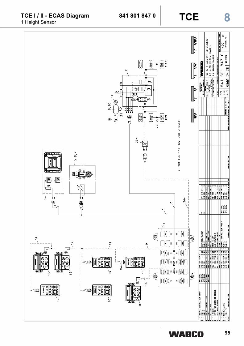
TCE I / II - ECAS Diagram 841 801 847 01 Height Sensor
TCE 8
2
96
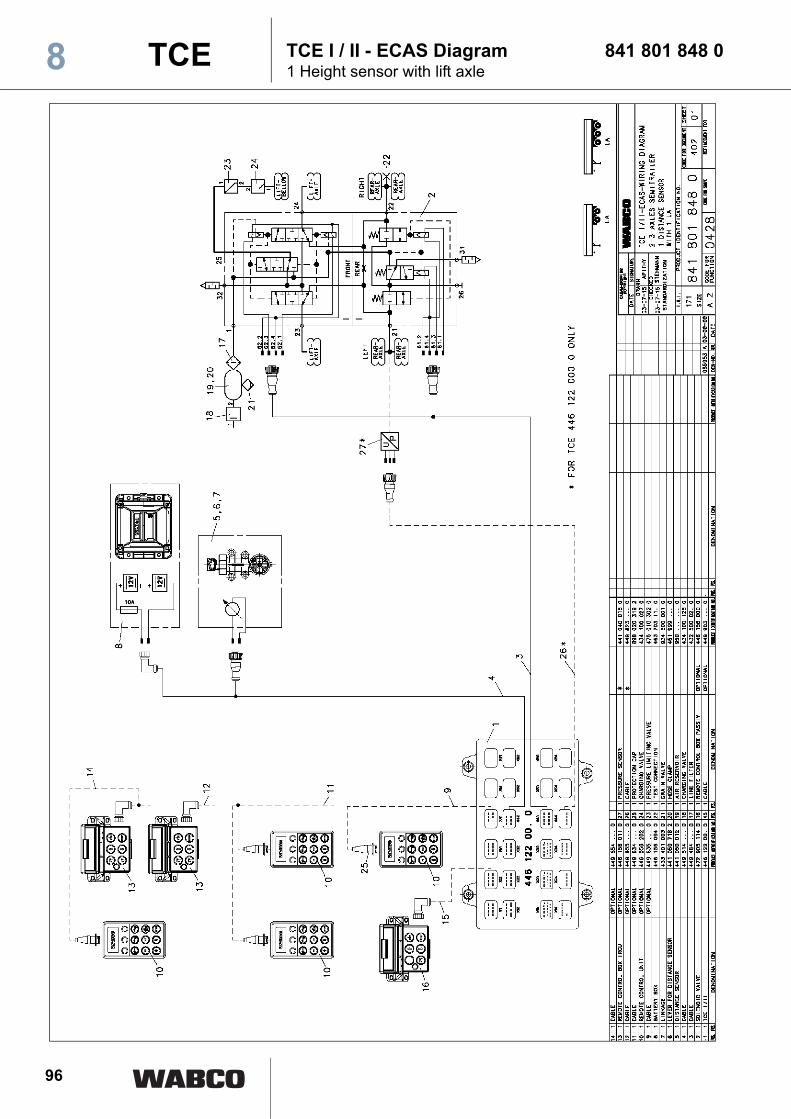
TCE I / II - ECAS Diagram 841 801 848 01 Height sensor with lift axle
TCE8
2

97
TCE I / II - ECAS Diagram 841 801 849 01 Height sensor with 2 lift axles
TCE 8
2

98
TCE I / II - ECAS Diagram 841 801 960 01 Height sensor with trailing axle control
TCE8
2

99
TCE I / II - ECAS Diagram 841 801 961 01 Height sensor with 1 lift axle
TCE 8
2
100
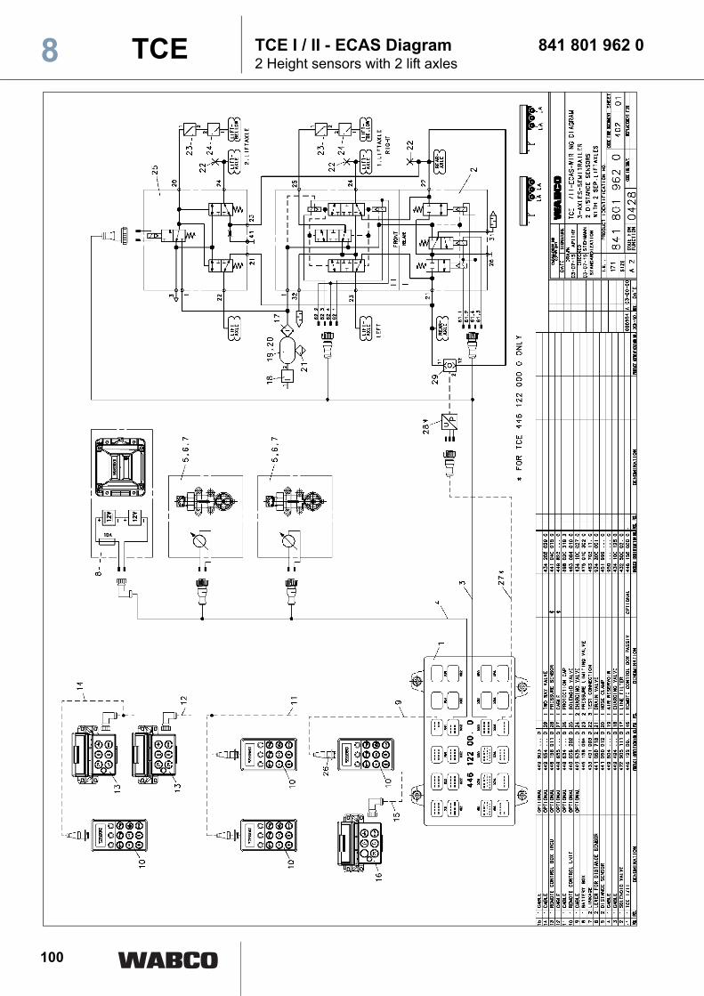
TCE I / II - ECAS Diagram 841 801 962 02 Height sensors with 2 lift axles
TCE8
2

101
TCE I / II - ECAS Diagram 841 801 963 02 Height sensors with axle load indication
TCE 8
2

102
TCE I / II - ECAS Diagram 841 801 964 01 Height sensor with 2 lift axles
TCE8
2
103
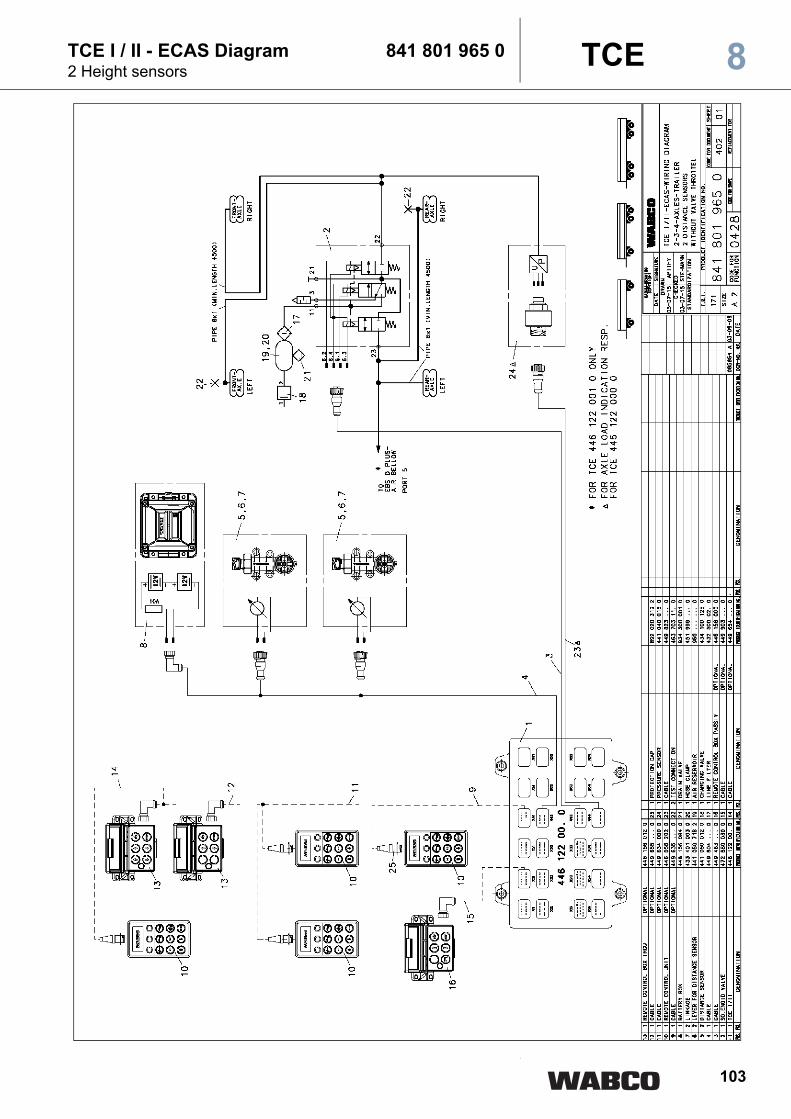
TCE I / II - ECAS Diagram 841 801 965 02 Height sensors
TCE 8
2
104
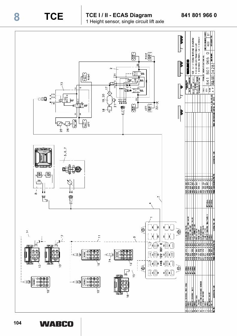
TCE I / II - ECAS Diagram 841 801 966 01 Height sensor, single circuit lift axle
TCE8
2

105
Supply cable with 449 113 000 0socket TCE 8
2
106
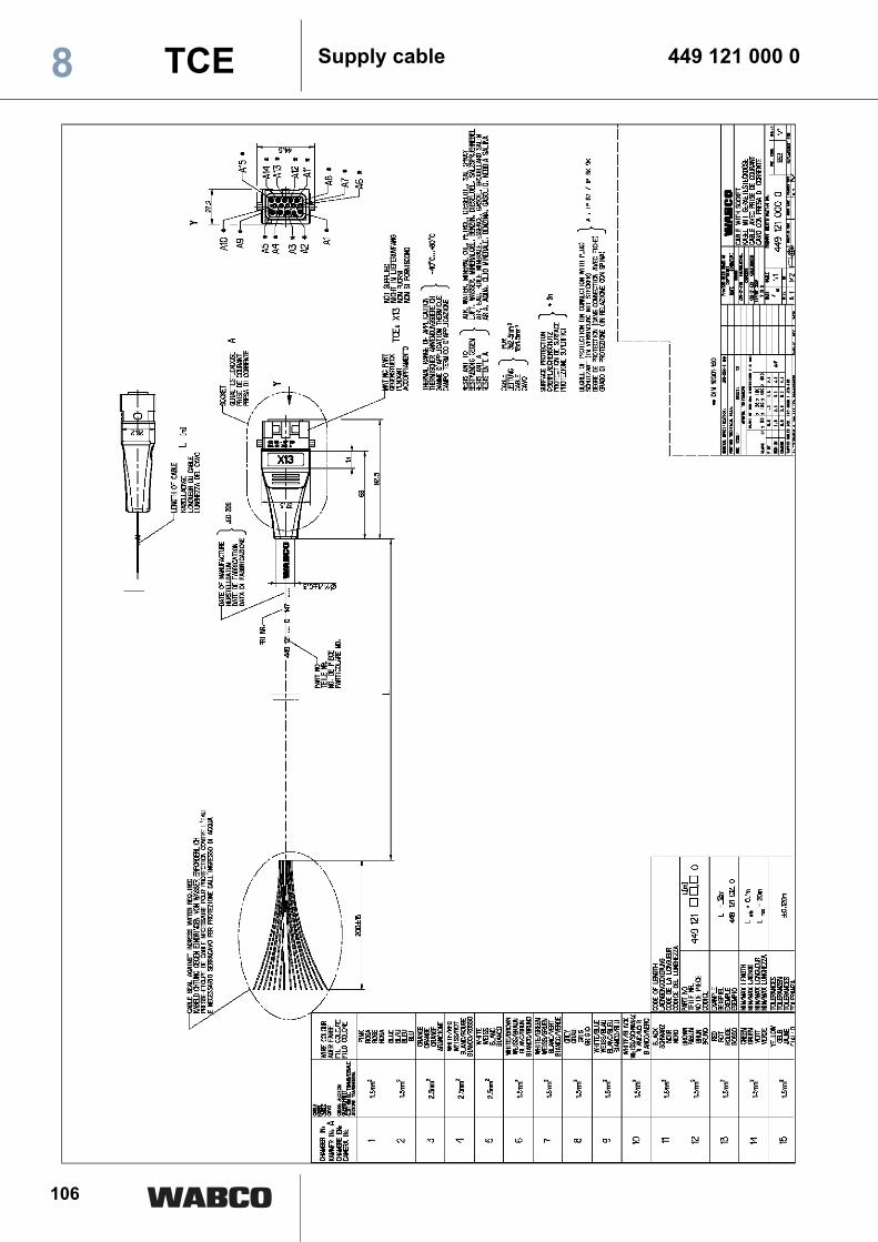
Supply cable 449 121 000 0TCE8
2
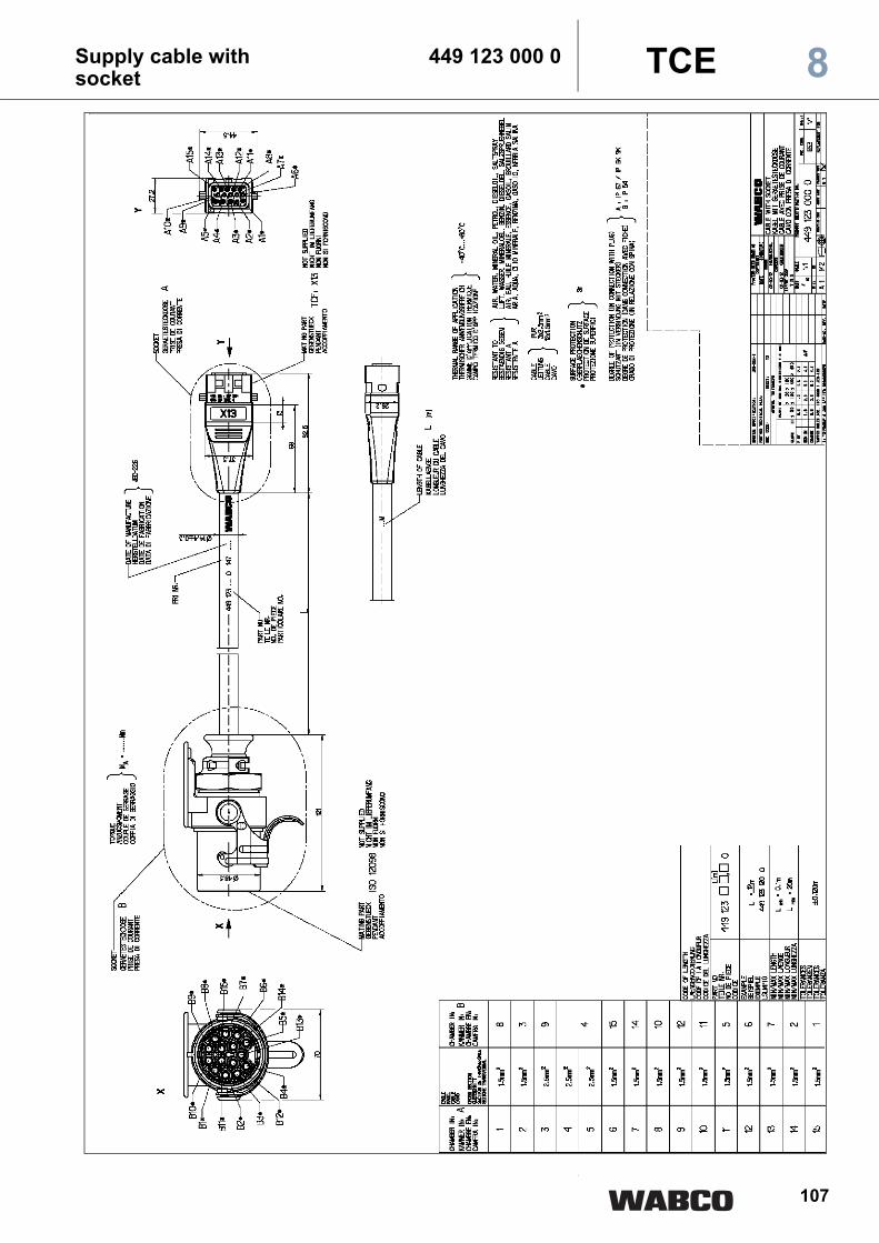
107
Supply cable with 449 123 000 0socket 8TCE
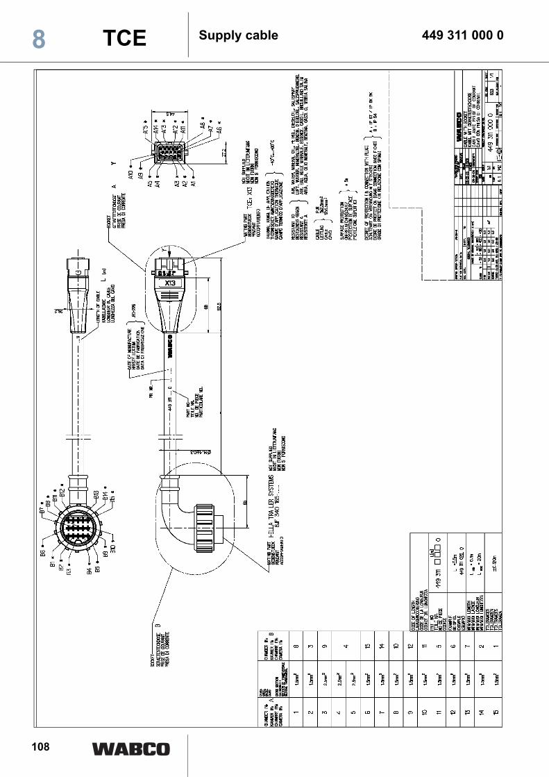
108
Supply cable 449 311 000 0TCE8
2

109
Supply cable with 449 133 000 0ABS-/EBS-socket TCE 8
2

110
Supply cable with 449 135 000 0Bayonet socket8 TCE

111
Supply cable with 449 172 000 0ABS-/EBS-socket 8TCE

112
Supply cable with 449 272 000 0ABS-/EBS-plug8 TCE
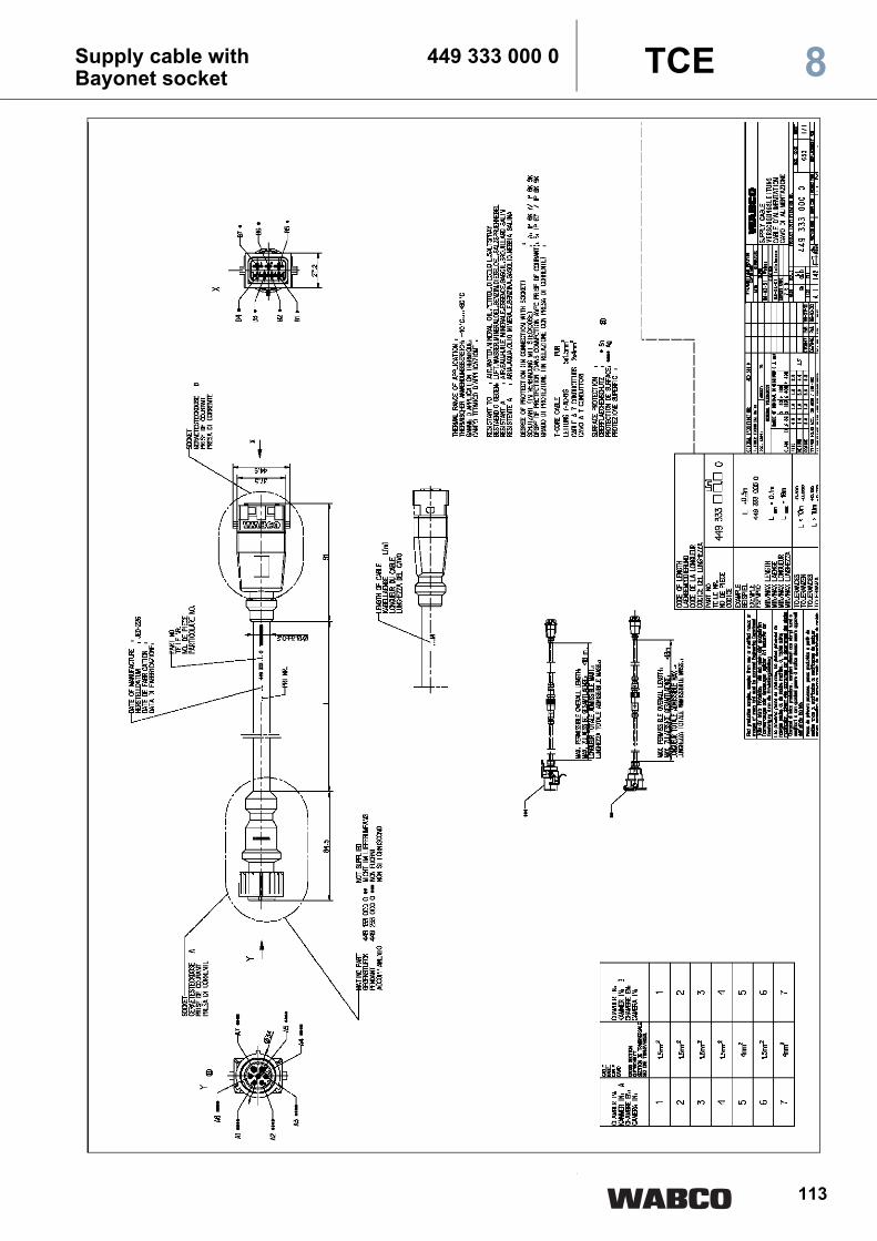
113
Supply cable with 449 333 000 0Bayonet socket 8TCE
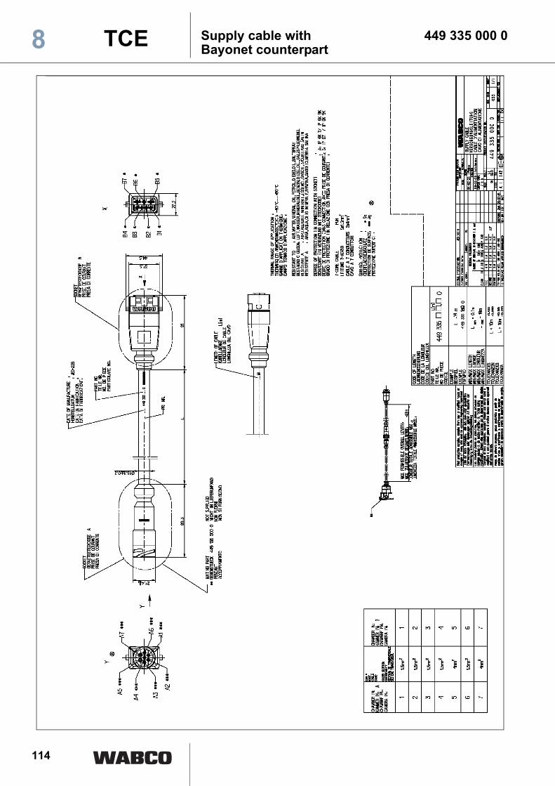
114
Supply cable with 449 335 000 0Bayonet counterpart8 TCE
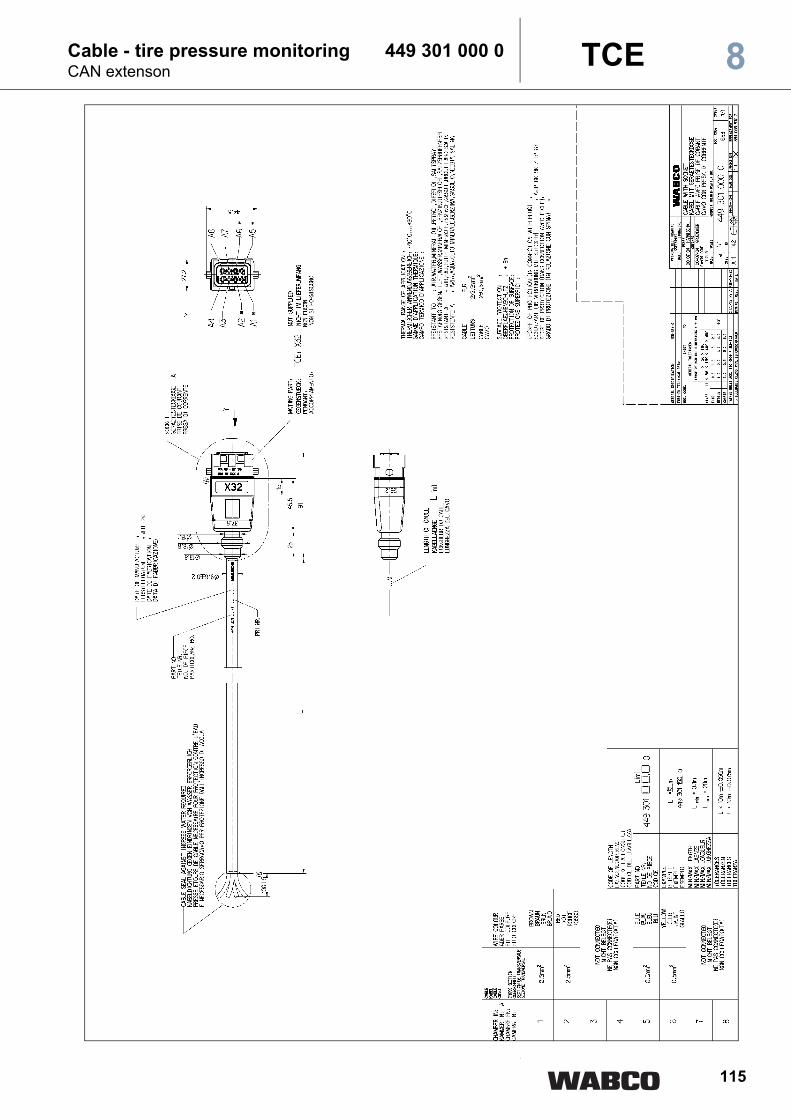
115
Cable - tire pressure monitoring 449 301 000 0CAN extenson 8TCE

116
Cable - tire pressure monitoring 449 302 000 08 TCE
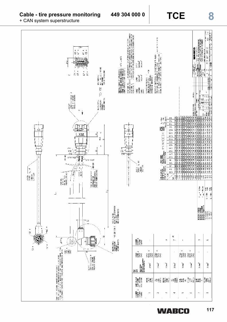
117
Cable - tire pressure monitoring 449 304 000 0+ CAN system superstructure 8TCE

118
Cable - tire pressure monitoring 449 391 000 08 TCE

119
Cable - tire pressure monitoring 449 392 000 0(Connection of lighting to underdrive protection) 8TCE
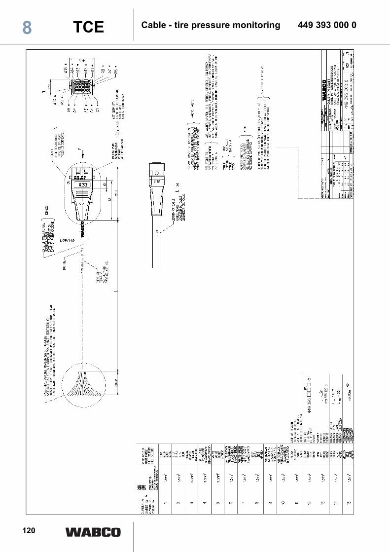
120
Cable - tire pressure monitoring 449 393 000 08 TCE
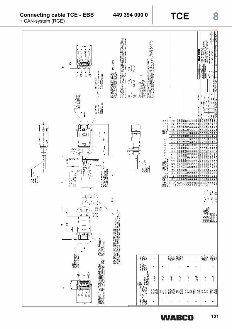
121
Connecting cable TCE - EBS 449 394 000 0+ CAN-system (RGE) 8TCE
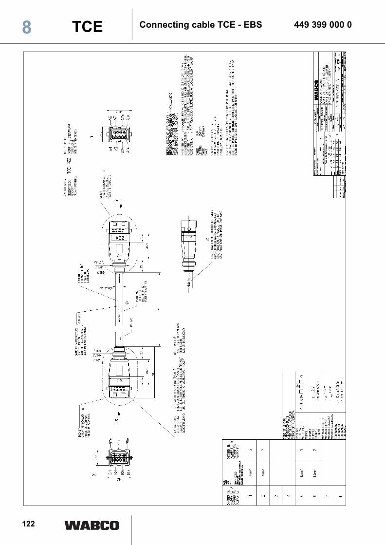
122
Connecting cable TCE - EBS 449 399 000 08 TCE
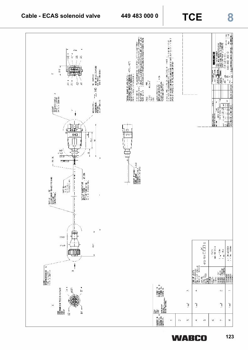
123
Cable - ECAS solenoid valve 449 483 000 0 8TCE

124
Cable - ECAS solenoid valve 449 484 000 0(1-/2- point control with lift axle)8 TCE

125
Cable - ECAS solenoid valve 449 485 000 0(1-/2- point control with lift axle) 8TCE
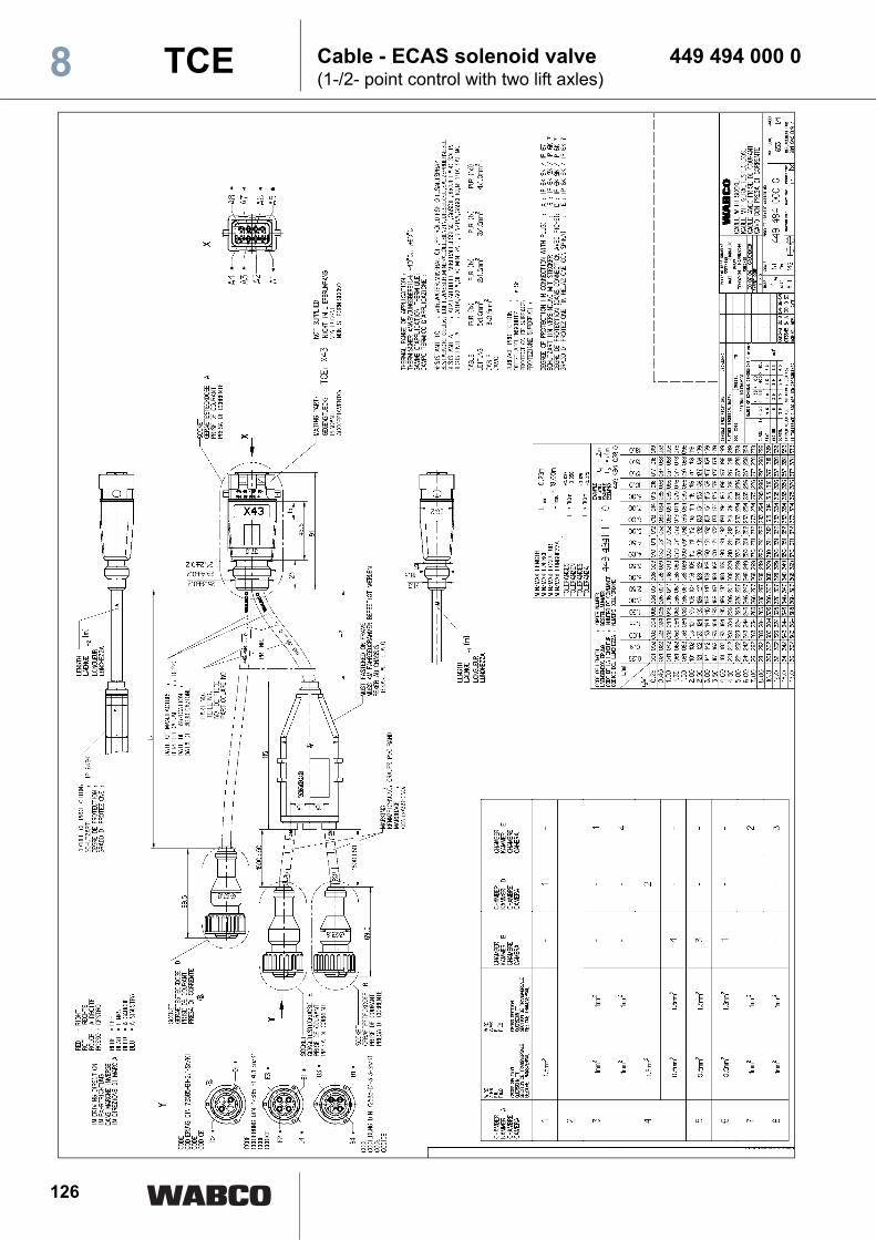
126
Cable - ECAS solenoid valve 449 494 000 0(1-/2- point control with two lift axles)8 TCE

127
Cable - tire pressure monitoring 449 604 000 0(Y cable for tank vehicles) 8TCE

128
Cable - ECAS control unit 449 634 000 0(Y cable for two control units)8 TCE

129
Cable - ECAS control unit 449 635 000 0 8TCE
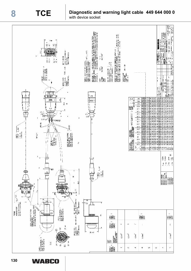
130
Diagnostic and warning light cable 449 644 000 0with device socket8 TCE
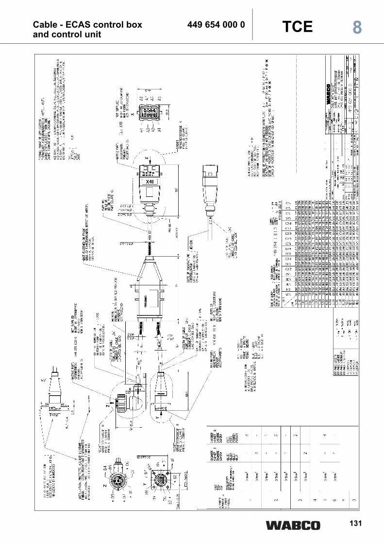
131
Cable - ECAS control box 449 654 000 0and control unit 8TCE

132
Cable - ECAS control box 449 655 000 08 TCE

133
Diagnostic cable with 449 672 000 0device socket 8TCE

134
Cable - ultra sonic sensors 449 704 000 0(Ramp approach help)8 TCE

135
Cable - ECAS height sensor 449 804 000 0(for two ECAS height sensors and one battery box) 8TCE

136
Cable - ECAS height sensor 449 814 000 0(for one ECAS height sensor and battery box)8 TCE

137
Cable - ECAS pressure sensor 449 823 000 0(for one pressure sensor) 8TCE

138
Cable - ECAS pressure sensor 449 824 000 0(for two pressure sensors) 8 TCE

139
Cable - brake lining wear 449 874 000 0indicator (limit value indicator) 8TCE
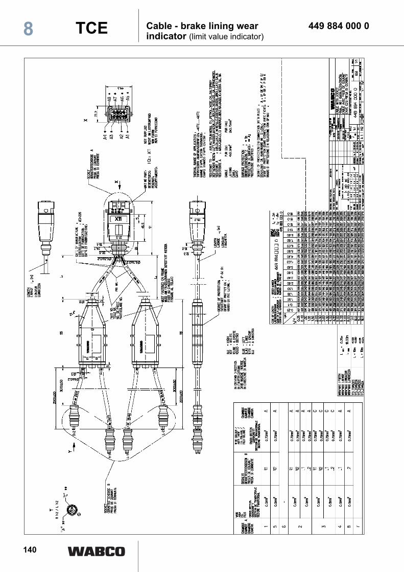
140
Cable - brake lining wear 449 884 000 0indicator (limit value indicator)8 TCE
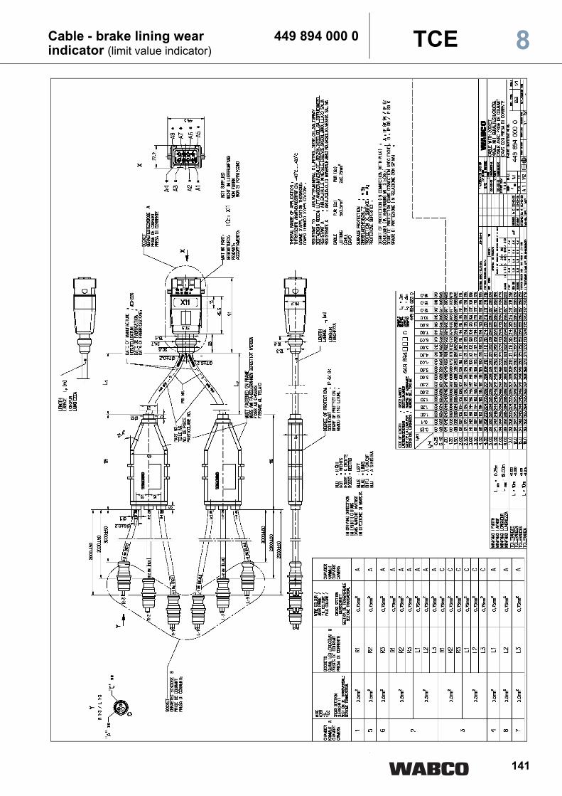
141
Cable - brake lining wear 449 894 000 0indicator (limit value indicator) 8TCE

142
Cable - extension 449 902 000 0(e.g. ECAS third control unit)8 TCE
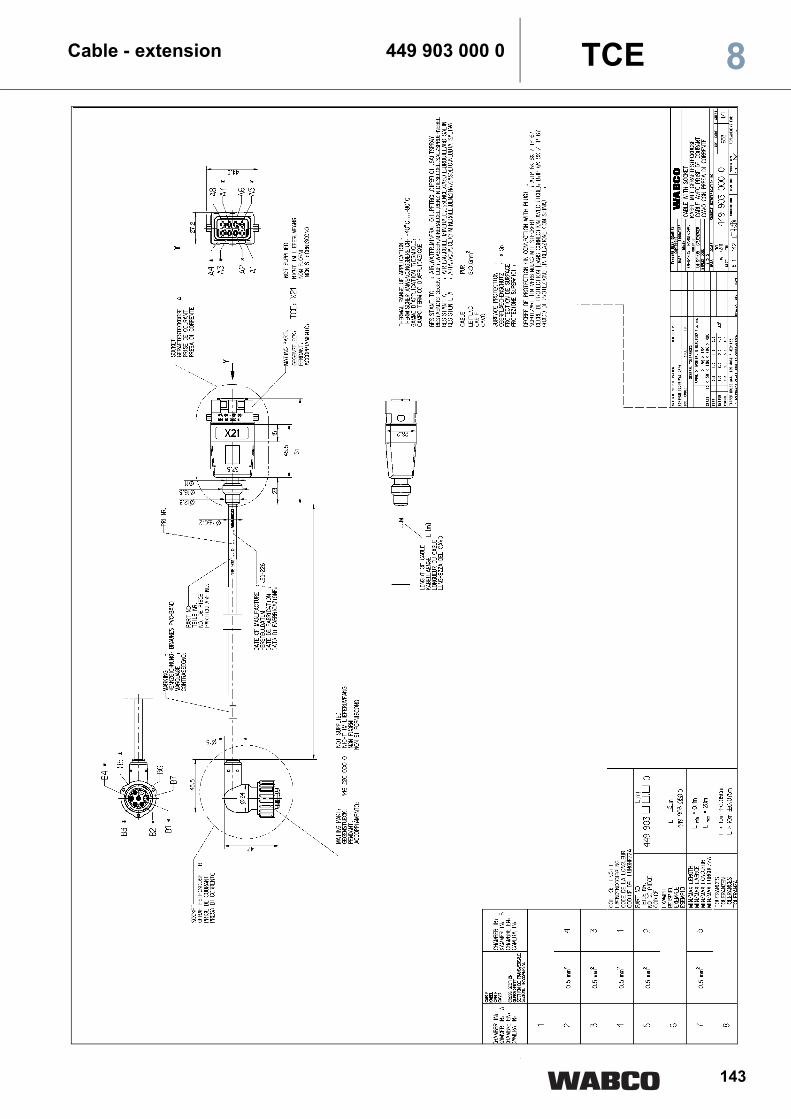
143
Cable - extension 449 903 000 0 8TCE
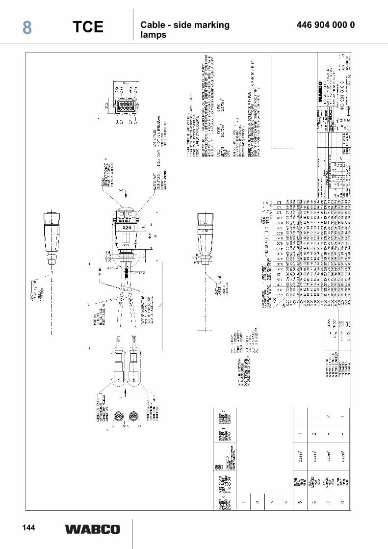
144
Cable - side marking 446 904 000 0lamps8 TCE
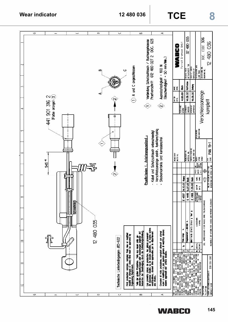
145
Wear indicator 12 480 036 8TCE
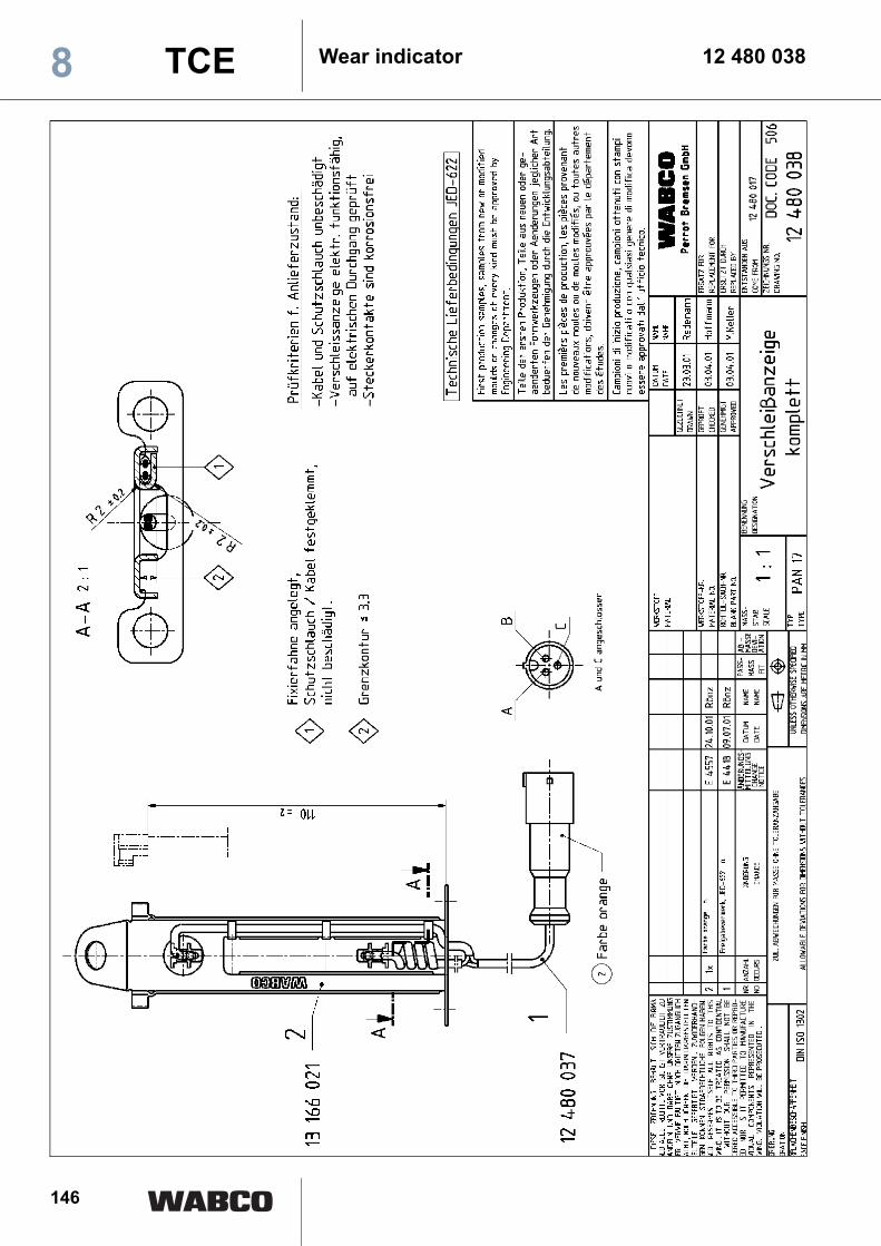
146
Wear indicator 12 480 0388 TCE
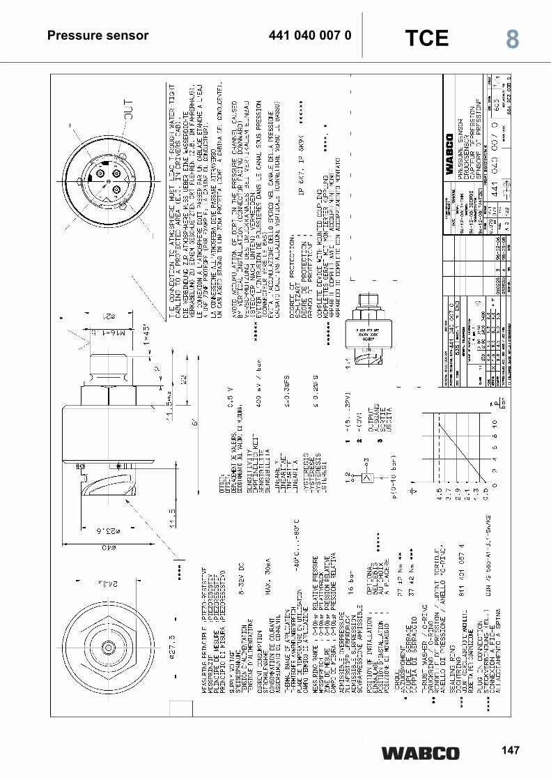
147
Pressure sensor 441 040 007 0 8TCE
148
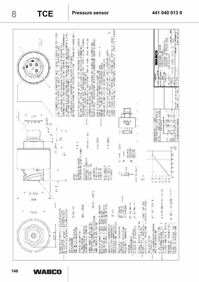
Pressure sensor 441 040 013 08 TCE

149
Pressure sensor 441 040 015 0 8TCE

150
Height sensor 441 050 012 08 TCE
151
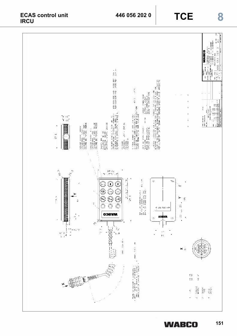
ECAS control unit 446 056 202 0IRCU 8TCE
152
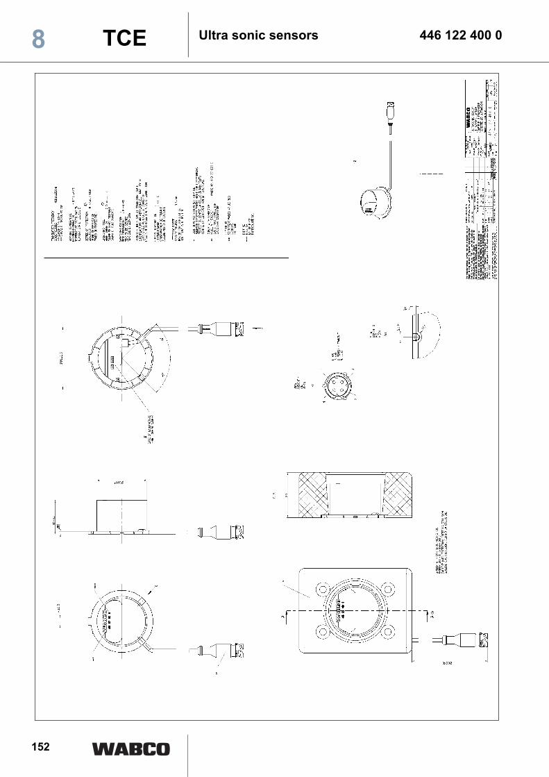
Ultra sonic sensors 446 122 400 08 TCE

153
Control box ECAS 446 156 000 0 8TCE

154
Battery box ECAS 446 156 090 0(without batteries)8 TCE

155
Battery box ECAS 446 156 094 0(without batteries) 8TCE

156
Diagnostic cable 446 300 329 2TCE8

157
Lift axle control valve 463 084 010 0 TCE 8
158
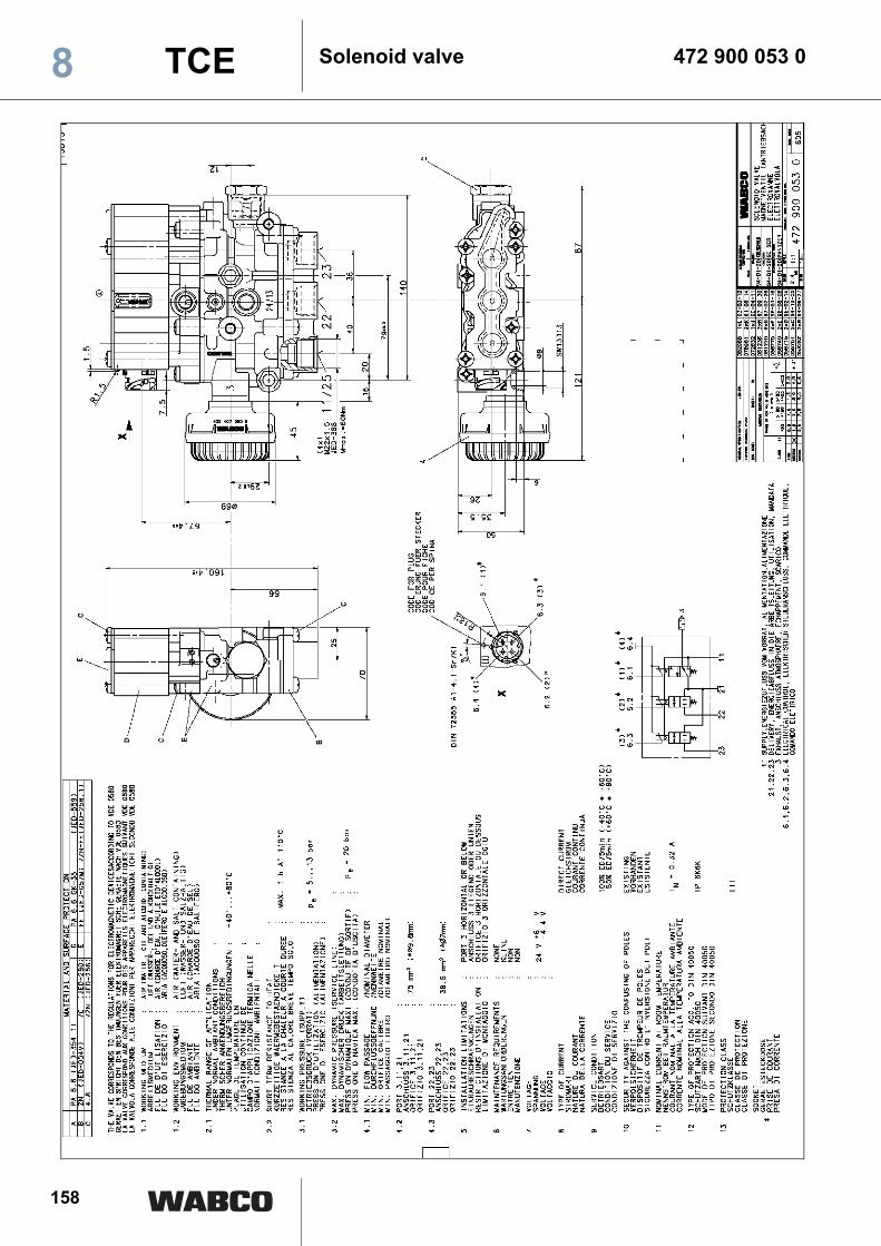
Solenoid valve 472 900 053 0TCE8

159
Solenoid valve 472 900 055 0 TCE 8
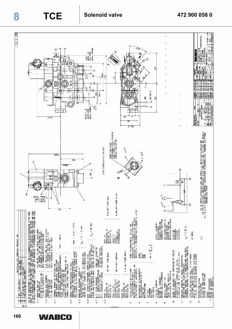
160
Solenoid valve 472 900 058 0TCE8

161
Solenoid valve 472 905 111 0 TCE 8

162
Solenoid valve 472 905 114 0TCE8

163
Solenoid valve 472 880 001 0 TCE 8
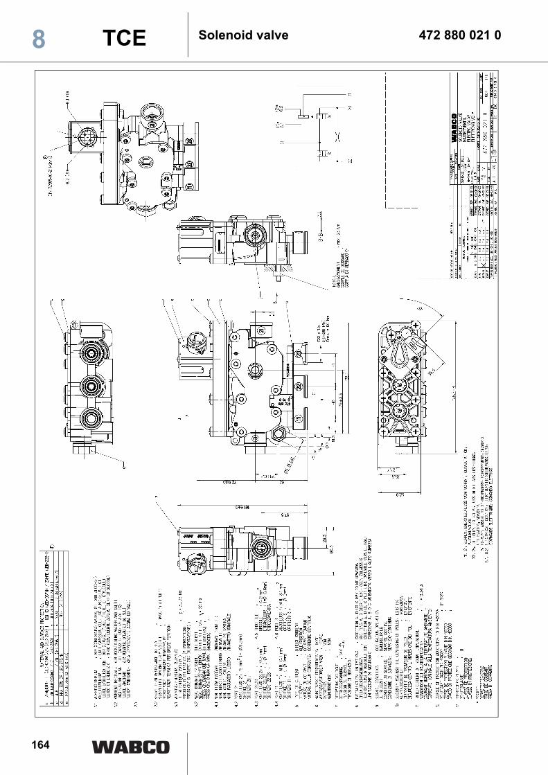
164
Solenoid valve 472 880 021 0TCE8

165
Solenoid valve 472 880 030 0 TCE 8

166
TCE8
2
What is required for TCE system startup?
Are all cables connected to EBS, TCE and the components and the plugs enclosed by the locking clip?
Utilize EBS modulator 480 102 002, connect pressure sensor and wear sensor to TCE and close plug connection at EBS.Utilize height sensor 441 050 012 0 and control unit 446 056 202 0.
Check whether all cables are suitably assigned in accordance with their color marking?
Are the Ohm loads of the lighting complied with (see plan 841 801 842 0)?
Are free terminals at TCE, EBS provided with caps?
Are cables before TCE ECU fixed in two wiring harnesses in a distance of 30 to 40 cm?
Vehicle must be completed.
Supply via 7-pin and 15-pin (resp. 2x7-pin) to be secured.
Are parameters and calibrating data available?
Start EBS PC diagnosis.
Start EBS system startup.
electr. outlets 1 + 2 must be active 'not available'.
Print protocol of system startup or save on PC.
Print system label and put it on the vehicle.
Start PC diagnosis.
Start system startup, select subsystems connected and to be checked and start system startup.
Print protocol of system startup or save on PC.
Print system label and put it on the vehicle.

167

168 2