tccs toyota computer controlled system
DESCRIPTION
DSDDDDTRANSCRIPT
training manual
VOLUME 1 STEP 3 /
TCCS (TOYOTA COMPUTER-CONTROLLED SYSTEM)
FOREWORD
This Training Manual has been prepared for the use of technicians employed by Toyota's overseasdistributors and dealers. This manual, "TCCS (Toyota Computer-Controlled System)", is Volume 1 ofthe thirteen Training Manuals which constitute Step 3 of the program of skills which all Toyota NewTEAM* technicians should master. It should also be used by the instructor in conjunction with theaccompanying Instruction Guide .
The titles of the New TEAM Step 3 Training Manuals are as follows :
VOL . TRAINING MANUALS VOL . TRAINING MANUALS
1 TCCS (Toyota Computer-Controlled System) 8 NVH (Noise, Vibration & Harshness )
2 Turbocharger & Supercharger 9 Fundamentals of Electronics
3 Diesel Injection Pump 10 CCS (Cruise Control System )
4 ECT ( Electronically-Controlled Transmission) 1 1 Car Audio Syste m
5 Full-Time 4WD 12 Automatic Air Conditioning Syste m
6 TEMS & Air Suspension 13 SRS Airbag & Seat Belt Pretensione r
7 ABS & Traction Control Syste m
It is not enough just to "know" or "understand" - you need to master each task so that you can doit . For this reason, theory and practice have been combined in this Training Manual . The top of eachpage is marked either with a Q symbol to indicate that it is a Theory page or a® symbol to indicatethat it is a Practice page .
Note that in regards to inspection and other procedures mentioned in the Practice section, thisTraining Manual contains only the main points to be learned ; please refer to the relevant RepairManual(s) for details .
The following notations often occur in this manual, with the meanings as explained :
A potentially hazardous situation which could result in injury to people may occur ifCAUTION
instructions are not followed .
NOTICE Damage to the vehicle or components may occur if instructions are not followed .
NOTE Notes or comments not included under the above two headings .
Information not required to pass the TEAM certification, but which may be useful t oREFERENCE
instructors and to trainess who wish to gain a deeper knowledge of the subject .
*TEAM : TEAM stands for 'Technical Education for Automotive Maste ry' , which is a training program divided into three stepsaccording to the technician's technical level . This program makes it possible for technicians to receive the appropriate training for theirlevel in a systematic manner so as to help them achieve the skills and efficiency of skilled technicians in the sho rtest possible time .

This Training Manual explains the TCCS engine control system based on the 4A-FE engine . However,representative engines other than the 4A-FE engine have sometimes been selected to explainmechanisms not found" on the 4A-FE engine . In this way, explanations of as many mechanisms aspossible have been included .
All information contained in this manual is the most up-to-date at the time of publication . However,we reserve the right to make changes without prior notice .
TOYOTA MOTOR CORPORATIO N
©1997 TOYOTA MOTOR CORPORATIONAll rights reserved . This book may not be repro-duced or copied, in whole or in part, without thewritten permission of Toyota Motor Corporation .

TABLE OF CONTENTSPage
ABBREVIATIONS AND ECU TERMINAL SYMBOL S
ABBREVIATIONS . . . . . . . . . . . . . . . . . . . . . . . . . . . . . . . . . . . 1
ECU TERMINAL SYMBOLS . . . . . . . . . . . . . . . . . . . . . . 2
OUTLINE OF TCC S
WHAT IS TCCS? . . . . . . . . . . . . . . . . . . . . . . . . . . . . . . . . . . . . 5
HISTORY OF TCCS ENGINE CONTROLSYSTEM . . . . . . . . . . . . . . . . . . . . . . . . . . . . . . . . . . . . . . . . . . . 6
SYSTEM DESCRIPTION . . . . . . . . . . . . . . . . . . . . . . . . . . 7
1 . Functions of engine control system . . . 8
2. Construction of engine controlsystem . . . . . . . . . . . . . . . . . . . . . . . . . . . . . . . . . . . . . . . . . . 10
3. Engine control system diagram . . . . . . . . . 1 2
ELECTRONIC CONTROL SYSTE M
GENERAL . . . . . . . . . . . . . . . . . . . . . . . . . . . . . . . . . . . . . . . . . . . . . . 13
POWER CIRCUITRY . . . . . . . . . . . . . . . . . . . . . . . . . . . . . . . . 15
1 . Engine without stepper motor typ eISC valve . . . . . . . . . . . . . . . . . . . . . . . . . . . . . . . . . . . . . . . 15
2. Engine with stepper motor typeISC valve . . . . . . . . . . . . . . . . . . . . . . . . . . . . . . . . . . . . . . . 16
VC CIRCUITRY . . . . . . . . . . . . . . . . . . . . . . . . . . . . . . . . . . . . . . 16
GROUND CIRCUITRY . . . . . . . . . . . . . . . . . . . . . . . . . . . . . 16
MANIFOLD PRESSURE SENSO R(VACUUM SENSOR) . . . . . . . . . . . . . . . . . . . . . . . . . . . 17
AIR FLOW METER . . . . . . . . . . . . . . . . . . . . . . . . . . . . . . . . . . 18
1 . Vane type . . . . . . . . . . . . . . . . . . . . . . . . . . . . . . . . . . . . . . 18
2 . Optical Karman vortex type . . . . . . . . . . . . . . 21
3 . Hot-wire type . . . . . . . . . . . . . . . . . . . . . . . . . . . . . . 21- 1
THROTTLE POSITION SENSOR . . . . . . . . . . . . . . . . 22
1 . On-off type . . . . . . . . . . . . . . . . . . . . . . . . . . . . . . . . . . . . 22
2 . Linear type . . . . . . . . . . . . . . . . . . . . . . . . . . . . . . . . . . . . 23
G AND NE SIGNAL GENERATORS . . . . . . . . . . . . 24
1 . In-distributor type . . . . . . . . . . . . . . . . . . . . . . . . . . . 24
2 . Cam position sensor type . . . . . . . . . . . . . . . . 27
3 . Separate type . . . . . . . . . . . . . . . . . . . . . . . . . . . . . . . . 28
WATER TEMPERATURE SENSOR . . . . . . . . . . . . . 30
INTAKE AIR TEMPERATURE SENSOR . . . . . . . 30
OXYGEN SENSOR (02 SENSOR) . . . . . . . . . . . 30- 1
1 . Zirconia element type . . . . . . . . . . . . . . . . . . . 30-1
2. Titania element type . . . . . . . . . . . . . . . . . . . . . . . . .32
LEAN MIXTURE SENSOR . . . . . . . . . . . . . . . . . . . . . . . . 33
Page
VEHICLE SPEED SENSOR . . . . . . . . . . . . . . . . . . . . . . . . 34
1 . Reed switch type . . . . . . . . . . . . . . . . . . . . . . . . . . . . 34
2 . Photocoupler type . . . . . . . . . . . . . . . . . . . . . . . . . . 34
3 . Electromagnetic pickup type . . . . . . . . . . . . 35
4. MRE type . . . . . . . . . . . . . . . . . . . . . . . . . . . . . . . . . . . . . . 36
STA SIGNAL . . . . . . . . . . . . . . . . . . . . . . . . . . . . . . . . . . . . . . . . . 38
NSW SIGNAL . . . . . . . . . . . . . . . . . . . . . . . . . . . . . . . . . . . . . . . . 38
A/C SIGNAL . . . . . . . . . . . . . . . . . . . . . . . . . . . . . . . . . . . . . . . . . . 39
ELECTRICAL LOAD SIGNAL . . . . . . . . . . . . . . . . . . . . 39
FUEL CONTROL SWITCH O RCONNECTOR . . . . . . . . . . . . . . . . . . . . . . . . . . . . . . . . . . . . . 40
EGR GAS TEMPERATURE SENSOR . . . . . . . . . . 40
VARIABLE RESISTOR . . . . . . . . . . . . . . . . . . . . . . . . . . . . . 41
KICK-DOWN SWITCH . . . . . . . . . . . . . . . . . . . . . . . . . . . . . 42
WATER TEMPERATURE SWITCH . . . . . . . . . . . . . 42
CLUTCH SWITCH . . . . . . . . . . . . . . . . . . . . . . . . . . . . . . . . . . 42
KNOCK SENSOR . . . . . . . . . . . . . . . . . . . . . . . . . . . . . . . . . . . . 43
HAC SENSOR . . . . . . . . . . . . . . . . . . . . . . . . . . . . . . . . . . . . . . . . 44
VAPOR PRESSURE SENSOR . . . . . . . . . . . . . . . . . . . . 44
TURBOCHARGING PRESSURE SENSOR . . . . 44
STOP LAMP SWITCH . . . . . . . . . . . . . . . . . . . . . . . . . . . . . 45
OIL PRESSURE SWITCH . . . . . . . . . . . . . . . . . . . . . . . . . 45
COMMUNICATIONS SIGNALS . . . . . . . . . . . . . . . . . 45
1 . Throttle opening angle signals . . . . . . . . . . 45
2 . Throttle opening angle signals fo rTRC system . . . . . . . . . . . . . . . . . . . . . . . . . . . . . . . . . . . 45
3. Cruise control systemcommunications signal . . . . . . . . . . . . . . . . . . . . 46
4. TRC system communications signal . . 46
5. ABS communications signal . . . . . . . . . . . . . 46
6. Intercooler system warning signal . . . . . 46
7 . EHPS system communication ssignal . . . . . . . . . . . . . . . . . . . . . . . . . . . . . . . . . . . . . . . . . . . . 47
8 . Engine speed signal . . . . . . . . . . . . . . . . . . . . . . . . 47
9 . Engine immobiliser syste mcommunications signal . . . . . . . . . . . . . . . . . . . . 47
DIAGNOSTIC TERMINAL(S) . . . . . . . . . . . . . .• .••••• 48
EFI (ELECTRONIC FUEL INJECTION )
GENERAL. . . . . . . . . . . . . . . . . . . . . . . . . . . . . . . . . . . . . . . . . . . . . . 49
TYPES OF EFI . . . . . . . . . . . . . . . . . . . . . . . . . . . . . . . . . . . . . . . . 52
1 . D-type EFI . . . . . . . . . . . . . . . . . . . . . . . . . . . . . . . . . . . . . 52
Z-L£ l. . . . . . . . . . . . . . . . . . . . . . . . . . . . . . . . . . . . . . . . . . . . . .
. II-080
9£1. . . . . . . . . . . . . . . indlno leulw ia3 ldn J0 3A 'Z
ti£L•••• suolioun} dwel „3NIJN3 )103H0„ L
££ """""""""' 1f1d1f10 lb'NIWa31l3n 8 0 dn (INb' dWt/l „ 3NIDN3 )103H0„
Z£ L"""' W31S AS 011SON OVIO 3O 3ldI0NI!!d
L C L . . . . . . . . . . . . . . . . . . . . . . . . . . . . . . . . . . . . . . . . . . . . ..lb'a3 N39SISONJtJI O
6Zl IN31S)lS 1Oa1N00 I V6Z l" * *"*'* " * . . . . . . . '*- ' W31S AS 10a1N00 St/
8Z L"""""""""""' VY31SAS 1081N00 SdH3
8Z VY31SAS 1O81N00 8 3Jab'H083dfl S
LZl VY31SAS 10a1N003Fif1SS3 8d 9 NI9at/H008!lfll
t,Z I. . . . . . . . . . . . . . . . . . . . . . . . . . . . . . . . . . . . . . . . . . . . . . . . . . .. SIA-1
ZZl Z adAl • Z
OZL . . . . . . . . . . . . . . . . . . . . . . . . . . . . . . . . . . . . . . . . . . L adAl • L
OZ l
L L LSlob'
VY31SAS AD S9 1. 1. """"""""""' 1N3WJOflf 3Nb'100 l3flj
9 L L"""""' W31S .lS 1 Oa1N00 d30-1f10 !!J3
9 L L"""""' Ia}uoo AeIaJ 4oin{o oi jau6eW • Z
5 L l. . . . . . . . . . . . . . . . . . . . . . . . . . . . . . . lojwoo }!o-3n0 L
5 L L-* VY31SAS 10lilN00 a3N011ION00 HIVt 'L l"""""""""""""" W31S.lS 108 1N00
831b'3H 8 0SN3S 3af11XIW Nb'31ti l l
. . . . . . . . . . . . . . . . . . . . . . . . . . . . . . . . . . . . . . . . . .. W31S.lS
10H1N00 a31d3H >:IOSN3S N3DA X0
til L""""W31SAS 1O!l1N00 d30-1f10 00 10 3
Ell
SIN3ISAS 1OalN00 a3H10
It/U31\139
I. L l""anIen OSI adAl ASA Iw Iuoo 110-u0 •V0 L l"' . . . anlen OSI adAl nOy loiluoo-Ain(] •E80l"' anlen OSI adA l pioualos A i e3oa •Z
90L"""""'anlen OSI adA l jo;ow jadda lS I.
90L""""""""" f103 3N10N3 30 SNOIl0Nf1 3
tlOl adA l ASA lo Jwoo };o-uO • t,VOL . . . . . . . . . . . . . . . . . . . . adAi n0</ lo jluoo-A jnO •E
ZOl"'. . . . . . . . . . . . . . . . . . . . adA1 ploualos Aj e3oa •Z
l0 L"' . . .' . . . . . . . . . . . . . . . . . . adAi jo1ow jaddaiS L
a6ed
L 0 l. . . . . . . . . . . . . . . . . . . . . . . . . . . . . . . . . . . . . . . . . . .
3 A lb'A OS I
66. . . . . . . . . . . . . . . . . . . . . . . . . . . . . . . . . . . . . . . . . . . . . . lb'H3N3 9
(10!l1N00 033dS 3101) OSI
86 •••••••••••••••• iuaw;snfpe 6uiwl3 uolllu6l Z
68. . . . . . . . . . . . . . . . . . . . . l 01 luoo 6ulwl3 uoliiu6l L
68 """"""""" f103 3NIJN3 d0 SNOIlONf13
88. . . . . . . . . . . . . . . . . . . . . . . . . . . . . . . . . . . . . . . . . . . . . . . SIG £
98. . . . . . . . . . . . . . . . . . . . . . . . . . . . . . . . . . . . wa3sAs Il0 ' Z
L ~8. . . . . . . . . . . . . . . . . . . . . . . . . . . . . . . . . . . . .
. SOOl J03Ajlmajlo uolllu6i leuol Juanuo0 • L
l-b8 . . . . . **'*** . . . . . . . . . . . . . . . AFJllflOalO NOIIINDIi ,8 . . . . . . . . . . . . . . . . . . . . . . . . . . . . . . . . . . . . . . . . . . . ltlNJIS 39I
E8. . . . . . . . . . . . . . . . . . . . . . . . . . . . . . . . . . . . . . . . .
. lb'N`JIS 19 I
E8 """"""' 1N3W39Oflf (3lJNb' DNIWI 1NOI11N9I l`dI11NI) 33DNb' ldb'HS>INb'!i0
L8 . . . . . Alilenb awlose6 pue 6ulwi l uo111u61 'Z
08. . . . . . . . . . . . . . . . . . . . . . . . . . . . . . . . . . . . . . . suol3lPuo o
6uluun i awu6a pue 6uiwil uol}1u61 • L
08. . . . . . . . . . . . . . . . . . . . . . . . . . . . . . . . . . . . . . . . . . . . . . lb'83N3`J
(30NVAOV )lat/dS OINOl110313) t/S 3
89 •••••••••• loi ;uoo uolleinp uolioaful and • Z
99. . . . . . . . . . . . . . . . . . . . . . . . . . . . . . . . . . . . . . . . . . . 6wwi l
uol ;oalw pue spo4iaw uolloalui land . L
99 """"""""" f103 3NIJN3 30 SNOIlONf13
99 . . . . . . . . . . . . . . . . . . . . . . . . . . . . . . . . . . . . . . . . . n I en J I b' Z99 . . . . . . . . . . . . . . . . . . . . . . . . . . . . . . . . . A o a 33ojP9 I 41' L
ti9 """"""""' W31Sl.S NOIlOf10NI HIVE9
. . . . . . . . . . . . . . . . . . . . . . . . . . . . . . . . . . . . . . . . Ajlmono
Z9
leoulaala J o loaful liels plo0
. . . . . . . . . . . . . . . . 4ollnns awll J010a1ul MISZ9
. . . . . . . . . . . . . . . . . . . . . . . . . . . 1 o30aful 1iels PIoO09 """"""""""' sP043ew anl J p J o33a 1 ul
69. . . . . . . . . . . . . . . . . . . . . . . . . . . . . . . . . . . . . . . . sioloafu I
89 . . . . . . . . . . . . . . . . . . . . . . . . . . . jo;eln6a j a inssaJ d
85. . . . . . . . . . . . . . . . . . . . . . . . . . . . jadwep uolleslnd
84. . . . . . . . . . . . . . . . . . . . . . . . . . . . . . . . . . . . . . . jaili} lend
99. . . . . . . . . . . . . . . . . . . . . . . . . . . loixuoo dwnd land
tr 5. . . . . . . . . . . . . . . . . . . . . . . . . . . . . . . . . . . . . dwnd le nd
E9. . . . . . . . . . . . . . . . . . . . . . . . . . . . . . . . . . . . . . .
0l
' 6
Z9 . . . . . . . . . . . . . 1=13 adAl-3 - Za6ed

Page
DIAGNOSTIC CODES . . . . . . . . . . . . . . . . . . . . . . . . . . . . . 138
FAIL-SAFE FUNCTIO N
FAIL-SAFE FUNCTION . . . . . . . . . . . . . . . . . . . . . . . . . . . . 14 5
BACK-UP FUNCTION
BACK-UP FUNCTION . . . . . . . . . . . . . . . . . . . . . . . . . . . . . . 14 7
TROUBLESHOOTIN G
GENERAL . . . . . . . . . . . . . . . . . . . . . . . . . . . . . . . . . . . . . . . . . . . . . . 149HOW TO CARRY OUTTROUBLESHOOTING . . . . . . . . . . . . . . . . . . . . . . . . . . 150
PRE-DIAGNOSTIC QUESTIONING . . . . . . . . . . . . . 152SYMPTOM CHART . . . . . . . . . . . . . . . . . . . . . . . . . . . . . . . . . 1 54
® CHECKING AND CLEARING DIAGNOSTICCODES
"CHECK ENGINE" LAMP CHECK . . . . . . . . . . . . . 159
OUTPUT OF DIAGNOSTIC CODES
1 . Normal mode . . . . . . . . . . . . . . . . . . . . . . . . . . . . . . . . . 15 9
2 . Test mode . . . . . . . . . . . . . . . . . . . . . . . . . . . . . . . . . . . . . 161CLEARING DIAGNOSTIC CODE . . . . . . . . . . . . . . . . 162
IS SYMPTOM SIMULATION . . . . . . . . . . . . . . . . . . . . . . . . . . . 163
® BASIC INSPECTION . . . . . . . . . . . . . . . . . . . . . . . . . . . . . . . . . . 167
INSPECTION AND ADJUSTMEN T
GENERAL . . . . . . . . . . . . . . . . . . . . . . . . . . . . . . . . . . . . . . . . . . . . . . 171IDLE SPEED AND IDLE MIXTURE . . . . . . . . . . . . . 172MANIFOLD PRESSURE SENSOR
(VACUUM SENSOR) . . . . . . . . . . . . . . . . . . . . . . . . . . . 175THROTTLE POSITION SENSO R
(LINEAR TYPE) AND THROTTL EBODY . . . . . . . . . . . . . . . . . . . . . . . . . . . . . . . . . . . . . . . . . . . . . . . 177
DISTRIBUTOR (G AND NE SIGNALS) . . . . . . . . 180INTAKE AIR TEMPERATURE SENSOR . . . . . . . 181FEEDBACK CORRECTION . . . . . . . . . . . . . . . . . . . . . . . 182Models with oxygen senso r
(02 sensor) . . . . . . . . . . . . . . . . . . . . . . . . . . . . . . . . . . . . 182Models with lean mixture sensor . . . . . . . . . . . 183
VARIABLE RESISTOR . . . . . . . . . . . . . . . . . . . . . . . . . . . . . 184ISC VALVE
(DUTY-CONTROL ACV TYPE) . . . . . . . . . . . . . . 186
Page
APPENDIX
ENGINE CONTROL SYSTE MSPECFICATION CHART . . . . . . . . . . . . . . . . . . . . . . . . 188
DELETED FOR NEW EDITIO N
. . . . . . . . . . . . . . . . . . . . 118, 119, 125, 126, 141 to 144,166 and 174

ABBREVIATIONS AND ECU TERMINAL SYMBOLS - Abbreviations4
ABBREVIATIONS AND ECU TERMINAL SYMBOLS
ABBREVIATION S
ABS Anti-Lock Brake System
ABV Air Bypass Valve
AC Alternating Current
A/C Air Conditione r
ACIS Acoustic Control Induction System
ACV Air Control Valve
Al Air Injection
AS Air Suction
ASV Air Switching Valve
A/T Automatic Transmission
BTDC Before Top Dead Center
CA Crankshaft Angl e
CALIF California
CCS Cruise Control System
CO Carbon Monoxid e
DIS Direct Ignition System
DLI Distributorless Ignition
EC European Countrie s
ECT Electronically-Controlled Transmission
ECU Electronic Control Unit
EFI Electronic Fuel Injection
EGR Exhaust Gas Recirculation
EHPS Electro-Hydraulic Power Steering
ESA Electronic Spark Advance
FED. Federal
GEN. General Countries
HAC High-Altitude Compensation
HC Hydrocarbo n
HIC Hybrid Integrated Circui t
IIA Integrated Ignition Assembly
ISC Idle Speed Contro l
LED Light Emitting Diode
LS Lean Mixture Sensor
MRE Magnetic Resistance Element
M/T Manual Transmission
NOx Oxides of Nitrogen
OC Oxidation Catalyst
OD Overdrive
02 Oxygen
PS Power Steering
SCV Swirl Control Valve
SST Special Service Tool
SW Switch
TCCS Toyota Computer-Controlled System
TDC Top Dead Cente r
TDCL *1 Toyota Diagnostic CommunicationLink or Total DiagnosticCommunication Link
TEMS Toyota Electronically-ModulatedSuspension
Tr Transistor
TRC*2 Traction Contro l
T-VIS Toyota-Variable Induction System
TWC Three-Way Catalyst
U.S. United States
VSV Vacuum Switching Valve
w/ With
w/o Without
4WD 4-Wheel-Driv e
In vehicles sold at Lexus dealers in the U.S . andCanada, this is called the "Total DiagnosticCommunication Link" . In Toyotas sold in othercountries, and in Toyotas sold at Toyota dealersin the U.S . and Canada, it is called the "ToyotaDiagnostic Communication Link" . In thismanual, it is called the "Toyota DiagnosticCommunication Link" .
*2 In the U .S . and Canada, this is abbreviated toTRAC.
/-- iw 1 c
Abbreviations in accordance with SAE terms
are used for vehicles sold in the U .S .A . and
Canada. Refer to the Repair Manual for dif-
ferences between SAE terms and Toyota
terms .
Example :
ECM Engine Control Module
(= Engine ECU )
ECT Engine Coolant Temperature
(= THW)
1

ABBREVIATIONS AND ECU TERMINAL SYMBOLS - ECU Terminal Symbol s
ECU TERMINAL SYMBOL S
SYMBOL MEANING
ABS Anti-Lock Brake System
ACC1 Acceleration Signal No . 1(fromThrott le Position Sensor)
ACC2 Acceleration Signal No . 2 (fromThrottle Position Sensor)
A/C Air Conditione r
ACMG Air Conditioner Magnetic Clutch
ACT Air Conditioner Cut-Off
Al Air Injection
AS Air Suctio n
A/D Auto Drive (Cruise Control System)
+B Battery+B1 Battery No. 1
BATT Batte ryBF Batte ry Fail Safe
BRK Brake
DFG Defogger
E01 Ea rth No. 01 (Ground)
E02 Earth No. 02 (Ground)
E1 Earth No. 1 (Ground)
E2 Earth No. 2 (Ground )
ECT Electronically-Controlled Transmission
ELS Electrical Load Signal
EGR Exhaust Gas Recirculation
FC Fuel Pump Contro l
FP Fuel Pump Control Relay
FPU Fuel Pressure-U p
FS Fail-Safe Relay
G Group (Crankshaft Angle Signal )
G1 Group No. 1 (Crankshaft Angle Signal)
G2 Group No. 2 (Crankshaft Angle Signal)
G- Group Minus (-)
HAC High-Altitude Compensatio n
HT Heater (for Oxygen Sensor or LeanMixture Sensor )
IDL Idle Switch (in Throttle PositionSensor )
IGDA Ignition Distribution Signal A
IGDB Ignition Distribution Signal B
IGF Ignition Failure (Confirmation) Signal
IGSW Ignition Switch
IGT Ignition Timing Signal
SYMBOL MEANIN G
ISC1 Idle Speed Control Signal No . 1
ISC2 Idle Speed Control Signal No . 2
ISC3 Idle Speed Control Signal No . 3
ISC4 Idle Speed Control Signal No . 4
KD Kick-Down
KNK Knock Sensor
KS Karman Signa l
L7 Throttle Valve Opening Signal No . 1
L2 Throttle Valve Opening Signal No . 2
L3 Throttle Valve Opening Signal No . 3
LP Lamp
LS Lean Mixture Sensor
LSW Lean Burn Switch
M-REL EFI Main Relay
N/C Neutral Clutch Switch
NE Number of Engine RevolutionsSigna l
NE- Number of Engine RevolutionsSignal Minus (- )
NEO Number of Engine RevolutionsSignal Outpu t
No.10 (for Injectors)
No.20 (for Injectors )
NSW Neutral Sta rt Switch
OX Oxygen Sensor
OX + Oxygen Sensor ~+
OIL Oil Pressure
OD Overdrive
PS Power Steering
PSW Power Switch (in Throttle PositionSensor )
PIM Pressure, Intake Manifol d
R-P Regular or Premium Gasoline Signal
RSC Rota ry Solenoid Valve Close d
RSO Rota ry Solenoid Valve Open
SCV Swirl Control Valv e
SPD Vehicle Speed
SP2 Vehicle Speed No . 2
SP2- Vehicle Speed No . 2 Minus (-)
STA Sta rter
STJ Cold Sta rt Injecto r
2

ABBREVIATIONS AND ECU TERMINAL SYMBOLS - ECU Terminal Symbol s
SYMBOL MEANING
STP Stop Lamp Switch
T Test Termina l
TE1 Test Terminal, Engine No . 1
TE2 Test Terminal, Engine No . 2
THA Thermo, Intake Ai r
THG Thermo, Exhaust Gas
THW Thermo, Wate r
TR Traction Contro l
T-VIS Toyota-Variable Induction System
TSW Water Temperature Switch
VAF Voltage, Air-Fuel Ratio Control
VB Voltage, Battery
VC Voltage, Constant
VF Voltage, Feedbac k
VG Voltage, Gram Intake Air
V-ISC VSV Type Idle Speed Control
VS Voltage, Slide Signa l
VSH Voltage, Sub-Throttle Angle
VTA Voltage, Throttle Angle
VTH Voltage, Throttle Angl e
W "CHECK ENGINE" Warning Lamp
WIN Warning Lamp, Intercooler
F4$
3

b
OW3W

OUTLINE OF TCCS - What is TCCS ?
OUTLINE OF TCCS
WHAT IS TCCS ?"TCCS" (Toyota Computer-Controlled System) is
the general name for a system which exercises
comprehensive and highly precise control of the
engine, drive train, brake system, and other
systems by means of an ECU* (electronic control
unit), at the heart of which is a microcomputer .
Previously, TCCS was used as an engine control
system for only EFI (electronic fuel injection),
ESA (electronic spark advance), ISC (idle speed
control), diagnosis, etc .
Later, control systems utilizing other separate
ECUs were developed and adopted for the
control of systems other than the engine also .
Currently, the term "TCCS" has come to mean a
comprehensive control system which incorpo-
®
rates control systems controlled by various ECUs
to ensure basic vehicle performance, not only
running, turning and stopping .
*At Toyota, a computer which controls each
type of system is called an "ECU" .
REFERENCE
On some vehicle models, the ECT has its own
ECU, called the "ECT ECU" . (The ECU for
engine control is called the "Engine ECU" in
this case .) On models in which the ECT does
not have its own separate ECU, the ECT uses
the ECU for engine control, which is then
called the "Engine and ECT ECU" .
TCCS
CONCEPTUAL DIAGRAM OF TCCS
This manual explains the TCCS type engine
control system . For details concerning other
systems (ECT, ABS, TEMS, etc .), please refer to
the training manual for each individual system .
OHP 1
In addition, this manual assumes that you have
mastered the contents of the manual for Step 2,
vol . 5 (EFI) . If you have not, please read that
manual carefully before beginning this one .
5

11 OUTLINE OF TCCS - History of TCCS Engine Control Syste m
HISTORY OF TCCS ENGINE CONTROL SYSTE M
The ECU used for conventional EFI in export
models beginning in 1979 was the analog circuit
type, which controlled the injection volume
based on the time required for a capacitor to be
charged and discharged .
The microcomputer-controlled type was added
beginning in 1981 . That was the beginning of the
engine control system using TCCS . Now,
however, the TCCS engine control system not
only controls EFI, but also ESA, which controls
ignition timing ; ISC, which controls the idlespeed, and other such advanced systems; as
well as the diagnostic, fail-safe, and back-up
functions .
CYL.
ARR .ENGINE MODELS
1980 1985 1990 199 5
K series ( 4K-E) -- ~
E series ( 3E-E) [2E-E, 4E-FE, 5E-FE ]
A series (4A-GE, 4AG-ZE )
[4A-FE, 5A-FE, 7A-FE ]
L4
S series ( 2S-E )
(1 S-i, 1S-E, 2S-E) 1 3S-FE, 5S-FE ,
3S-GE, 3S-GTE ]
R series ( 22R-E )
(22R-TE) [22R-E] ~
Y series ( 3Y-E )
[4Y-E ]
RZ series [1RZ-E, 2RZ-E, 2RZ-FE, 3RZ-FE 1TZ series [2TZ-FE, 2TZ-FZE] ~
G series ( 1G-E)[1G-FE ]
(1G-GE)
-----~
~
L6
M series (4M-E, 5M-E, 5M-GE )
(5M-GE, 6M-GE, 7M-GE, 7M-GTE )
JZ series [2JZ-GE, 2JZ-GTE] ~
F series (3F-E) ~
FZ series [ 1 FZ-FE ]
V6VZ series (2VZ-FE)[3VZ-E, 3VZ-FE, 5VZ-FE ]
MZ series [1 MZ-FE]
V8 UZ series [1UZ-FE ]
INTAKE AIR SENSING DEVICES
Vane type air flow meter -
Manifold pressure (vacuum) senso r
Optical Karman vortex type air flow mete r
Hot-wire type mass air flow meter -
1 : No longer in production models
I I : Current product models
---~ : EFI (EFI control only )
TCCS (EFI, ESA, ISC, Diagnosis, etc )
6

OUTLINE OF TCCS - System Description
SYSTEM DESCRIPTIO N
The functions of the engine control system In addition, there are auxiliary engine control
include EFI, ESA, and ISC, which control basic devices on the engine, such as the OD cut-off con-
engine performance ; a diagnostic function, trol system, intake air control system, and others .
which is useful when repairs are made ; and fail- These functions are all controlled by the Engine
safe and back-up functions, which operate when ECU .
any of these control systems malfunction .
Manifold pressuresensor
Fuel pum p
Knock sensor
Distributor ,(and ignite r
Water temp . sensor
"E
Ignition switch
Circuit opening relay
Engine EC U
Variable resistor '
Check connector
Idle speed controlvalve
Intake air temp . senso r
"Applicable only to General Country specification vehicles without oxygen sensor .
LAYOUT OF ENGINE CONTROL SYSTEM COMPONENTS(COROLLA 4A-FE ENGINE FOR EUROPE Apr ., 1992)
7
0 OUTLINE OF TCCS - System Descriptio n
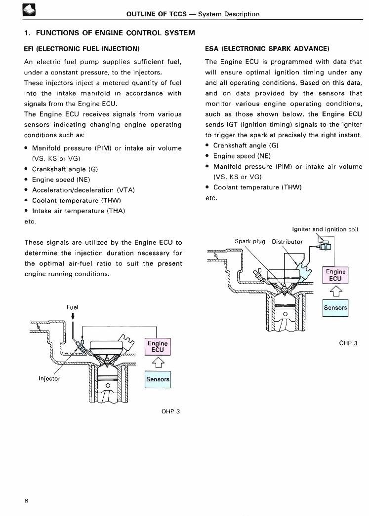
1 . FUNCTIONS OF ENGINE CONTROL SYSTE M
EFI (ELECTRONIC FUEL INJECTION )
An electric fuel pump supplies sufficient fuel,
under a constant pressure, to the injectors .
These injectors inject a metered quantity of fuel
into the intake manifold in accordance with
signals from the Engine ECU .
The Engine ECU receives signals from various
sensors indicating changing engine operating
conditions such as :
• Manifold pressure (PIM) or intake air volume
(VS, KS or VG )
• Crankshaft angle (G)
• Engine speed (NE )
• Acceleration/deceleration (VTA)
• Coolant temperature (THW )
• Intake air temperature (THA)
etc .
ESA (ELECTRONIC SPARK ADVANCE )
The Engine ECU is programmed with data that
will ensure optimal ignition timing under any
and all operating conditions . Based on this data,
and on data provided by the sensors that
monitor various engine operating conditions,
such as those shown below, the Engine ECU
sends IGT (ignition timing) signals to the igniter
to trigger the spark at precisely the right instant .
• Crankshaft angle (G )
• Engine speed (NE)
• Manifold pressure ( PIM) or intake air volume
(VS, KS or VG )
• Coolant temperature (THW)
etc .
Igniter and ignition coi l
These signals are utilized by the Engine ECU to
determine the injection duration necessary for
the optimal air-fuel ratio to suit the present
engine running conditions .
Fue l
+
EngineECU
Sensors
OHP 3
Sensors
OHP 3
8

OUTLINE OF TCCS - System Description
ISC (IDLE SPEED CONTROL )
The Engine ECU is programmed with target
engine speed values to respond to different
engine conditions such as :
• Coolant temperature (THW)
• Air conditioner on/off (A/C)
etc .
Sensors transmit signals to the Engine ECU,
which, by means of the ISC valve, controls the
flow of air through the throttle valve bypass and
adjusts the idle speed to the target value .
ISC valve
DIAGNOSTIC FUNCTION
The Engine ECU is constantly monitoring the
signals that are input to it from the various
sensors . If it detects any malfunctions in the
input signals, the Engine ECU stores data on the
malfunction in its memory and lights the
"CHECK ENGINE" lamp . When necessary, it
displays the malfunction by lighting the "CHECK
ENGINE" lamp, displaying on a tester* or output-
ting a voltage signal .
* OBD-II scan tool or TOYOTA hand-held teste r
"CHECK ENGINE" lamp
OHP 4
Sensors
OHP 4
FAIL-SAFE FUNCTIO N
If the signals input to the Engine ECU are
abnormal, the Engine ECU switches to standard
values stored in its internal memory to control
the engine. This makes it possible to control the
engine so as to continue more-or-less normal
vehicle operation .
BACK-UP FUNCTIO N
Even if the Engine ECU itself becomes partially
inoperative, the back-up function can continue to
execute fuel injection and ignition timing
control . This makes it possible to control the
engine so as to continue more-or-less normal
vehicle operation .
OTHER CONTROL SYSTEM S
In some engines, the OD cut-off control system,
intake air control system, and some other aux-
iliary systems are also controlled by the Engine
ECU .
9

® OUTLINE OF TCCS - System Descriptio n
2. CONSTRUCTION OF ENGINE CONTROL SYSTE M
BLOCK DIAGRAM
The engine control system can be broadly The sensors and actuators which form the basis
divided into three groups : the sensors, the of an engine control system used in an engineEngine ECU and the actuators. with an oxygen sensor are shown below.
SENSOR S
MANIFOLD PRESSURE I I I I EFISENSOR (D-TYPE EFI )
AIR FLOW METER*2(L-TYPE EFI )
DISTRIBUTOR----------------------------• Crankshaft angle signa l• Engine speed signa l
WATER TEMP . SENSO R
INTAKE AIR TEMP . SENSO R
THROTTLE POSITION SENSO R
• Idling signa l• Throttle position signa l
IGNITION SWITCH(ST TERMINAL )
• Starting signa l
VEHICLE SPEED SENSO R
OXYGEN SENSO R
VARIABLE RESISTOR- 3
NEUTRAL START SWITC H
TAILLIGHT &DEFOGGER RELAY S
AIR CONDITIONE R
KNOCK SENSO R
CHECK CONNECTOR
OXYGEN SENSOR HEATERCONTRO L
OXYGEN SENSOR HEATE R
FUEL PUMP CONTRO L
CIRCUIT OPENING RELAY
CHECK ENGINE LAMP(Diagnostic code display )
PIM ~10
VS, KS #20or VG
G
NE
THW
THA
ID L
TA
STA
SPD
OX
VAF
NSW
ELS
A/C
KN K
TE
TE
IGT
IG F
ISC
RSCENGINE IRSO IECU
H T
FC
W
BATT I 1 +13BATTERY I I EFI MAIN RELA Y
* 1* 2
*3
Actuators only related profoundly to the engine control are shown here .
Although a D-type EFI is shown in the above figure and a L-type EFI sensor is also shown for reference .
Applicable only to General Country specification vehicles without oxygen sensor .
ACTUATORS* '
NO .1 AND 3 INJECTOR S
NO .2 AND 4 INJECTOR S
ESA
IGNITE R
iIGNITION COIL
iDISTRIBUTO R
tSPARK PLUG S
ISC
IDLE SPEED CONTROL VALV E
COROLLA 4A-FE ENGINE FOR EUROPE (Apr., 1992)
10
OUTLINE OF TCCS - System Description
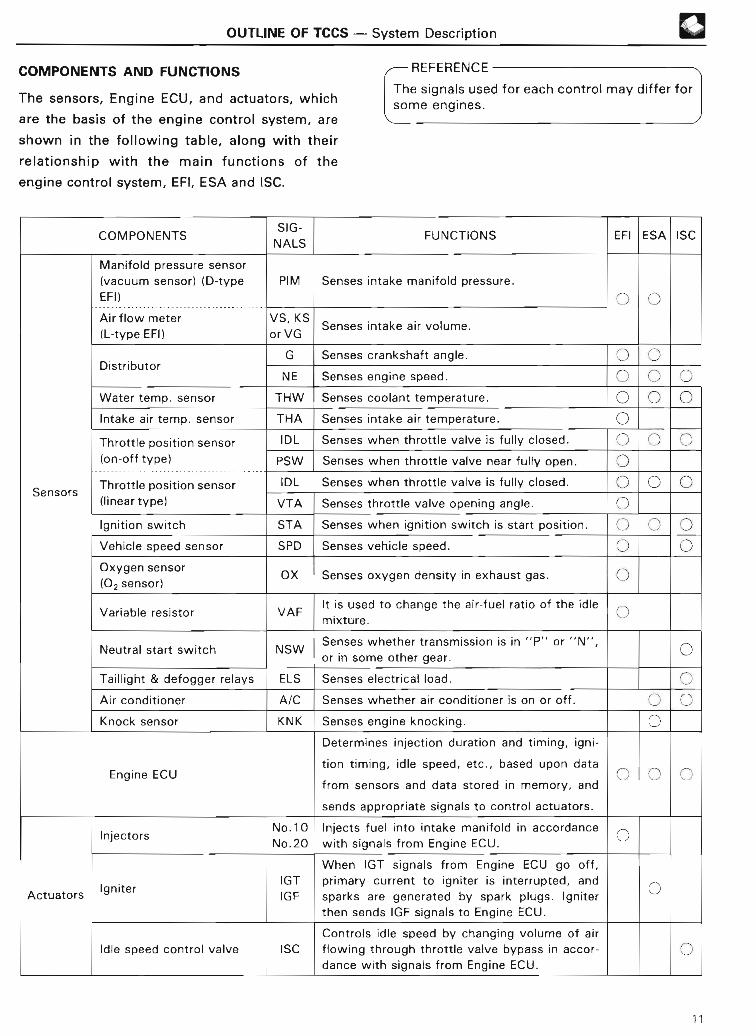
COMPONENTS AND FUNCTION S
The sensors, Engine ECU, and actuators, which
are the basis of the engine control system, are
shown in the following table, along with their
relationship with the main functions of the
engine control system, EFI, ESA and ISC .
®
REFERENCE
The signals used for each control may differ forsome engines .
COMPONENTSSIG-
FUNCTIONS EFI ESA IS CNAL S
Manifold pressure senso r
( vacuum sensor) ( D-type PIM Senses intake manifold pressure .
EFI )
Air flow meter VS, KS Senses intake air volume .(L-type EFI) or VG
G Senses crankshaft angle .Distributor
NE Senses engine speed .
Water temp . sensor THW Senses coolant temperature .
Intake air temp . sensor THA Senses intake air temperature .
Throttle position sensor IDL Senses when throttle valve is fully closed .
(on-off type) PSW Senses when throttle valve near fully open .
Throttle position sensor IDL Senses when throttle valve is fully closed .Sensors
( linear type) VTA Senses throttle valve opening angle .
Ignition switch STA Senses when ignition switch is start position .
Vehicle speed sensor SPD Senses vehicle speed .
Oxygen sensor OX Senses oxygen density in exhaust gas .(02 sensor)
It is used to change the air-fuel ratio of the idl eVariable resistor VAF
mixture .
Senses whether transmission is in "P" or "N" ,Neutral start switch NSW
or in some other gear .
Taillight & defogger relays ELS Senses electrical load .
Air conditioner A/C Senses whether air conditioner is on or off .
Knock sensor KNK Senses engine knocking .
Determines injection duration and timing, igni -
tion timing, idle speed, etc., based upon dat aEngine ECU
from sensors and data stored in memory, an d
sends appropriate signals to control actuators .
No .10 Injects fuel into intake manifold in accordanc eInjectors
No .20 with signals from Engine ECU .
When IGT signals from Engine ECU go off ,
IGT primary current to igniter is interrupted, an d
ActuatorsIgniter
IGF sparks are generated by spark plugs . Ignite r
then sends IGF signals to Engine ECU .
Controls idle speed by changing volume of ai r
Idle speed control valve ISC flowing through throttle valve bypass in accor -
dance with signals from Engine ECU .
11

a OUTLINE OF TCCS - System Description
3 . ENGINE CONTROL SYSTEM DIAGRAM
Neutral startswitch
~
~Check connecto r
Pressure regulator /
Injector
Circuit opening
relay
Fuel pump
Speed
sensor
J
Combinationmete r
Fuel tank
Air
conditioner
amplifier
i f
Engine EC U
Distributor andignite r
Knock
sensor
Variableresistor *
Oxygen sensor
(02 sensor)
/
r
Water temp . sensor
Battery
TWC
*Applicable only to General Country specification vehicles without oxygen sensor .
COROLLA 4A-FE ENGINE FOR EUROPE (Apr ., 1992)
Taillight relay
Defogger relay
r-o~ Ignition switch
CHECK~ ENGINE "
~ lamp
12
ELECTRONIC CONTROL SYSTEM - Genera l
ELECTRONIC CONTROL SYSTE M
GENERAL
The engine control system can be divided into
three groups: sensors (and the signals output by
them), the ECU, and actuators . This section
describes only the sensor (signal) systems.
ECU functions are divided into EFI control, ESA
control, ISC control, diagnostic function, fail-safe
function, back-up function and others . Each of
these functions is covered in a separate section
of this manual .
Actuator functions are also covered in a
separate section .
411
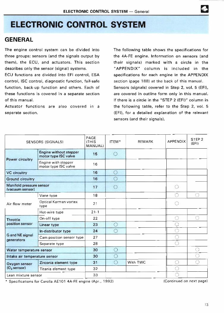
The following table shows the specifications for
the 4A-FE engine . Information on sensors (and
their signals) marked with a circle in the
"APPENDIX" column is included in the
specifications for each engine in the APPENDIX
section (page 188) at the back of this manual .
Sensors (signals) covered in Step 2, vol . 5 (EFI),
are covered in outline form only in this manual .
If there is a circle in the "STEP 2(EFI)" column in
the following table, refer to the Step 2, vol . 5
(EFI), for a detailed explanation of the relevant
sensors (and their signals) .
SENSORS (SIGNALS)PAG E(THI SMANUAL)
ITEM REMARK APPENDIX STEP 2(EFI )
Engine without steppe rmotor type ISC valve
15 0
Power circuitryEngine with steppe rmotor type ISC valve
1 6
VC circuitry 16 0Ground circuitry 16 0Manifold pressure senso r(vacuum sensor)
17 0
Vane type 1 8
Air flow meterOptcal Karman vorte xtype 2 1
Hot-wire type 21- 1
Throttle On-off type 22
position sensor Linear type 23 0
In-distributor type 24G and NE signa l
eneratorsCam position sensor type 27
gSeparate type 28
Water temperature sensor 30
Intake air temperature sensor 30
Oxygen sensor Zirconia element type 31 With TWC
(02 sensor) Titania element type 3 2
Lean mixture sensor 3 3
` Specifications for Carolla AE101 4A-FE engine (Apr ., 1992) (Continued on next page )
13
ELECTRONIC CONTROL SYSTEM - Genera l
SENSORS (SIGNALS)PAG E(THIS ITEM* REMARK APPENDIX STEP 2
MANUAL) (EFI )
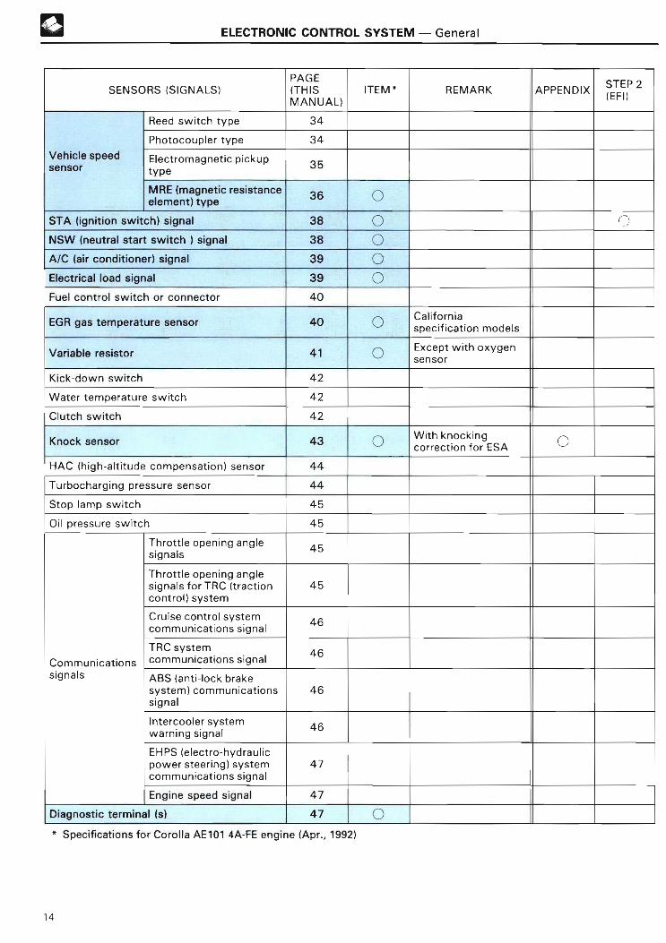
Reed switch type 34
Photocoupler type 34
Vehicle speed Electromagnetic pickup3 5sensor type
MRE (magnetic resistance36 ~
element) type
STA (ignition switch) signal 38 J ~
NSW (neutral start switch 1 signal 38
A/C (air conditioner) signal 39 0Electrical load signal 39 0Fuel control switch or connector 40
EGR gas temperature sensor 40 r~ Californi aspecification model s
Variable resistor 41 C Except with oxyge n
senso r
Kick-down switch 42
Water temperature switch 42
Clutch switch 42
Knock sensor 43With knockingcorrection for ES A
HAC (high-altitude compensation) sensor 44
Turbocharging pressure sensor 44
Stop lamp switch 45
Oil pressure switch 45
Throttle opening angle45
signal s
Throttle opening angl esignals for TRC (traction 4 5control) syste m
Cruise control system4 6
communications signa l
TRC system4 6
Communications communications signa l
signals ABS (anti-lock brak esystem) communications 4 6signa l
Intercooler system4 6
warning signa l
EHPS lelectro-hydrauli cpower steering) system 4 7communications signa l
Engine speed signal 4 7
Diagnostic terminal (s) 4 7
• Specifications for Corolla AE101 4A-FE engine (Apr ., 1992 )
14

ELECTRONIC CONTROL SYSTEM - Power Circuitry
POWER CIRCUITRY
This circuitry supplies power to the Engine ECU,
and includes the ignition switch and the EFI main
relay. There are two types of this circuitry in
use. In one, current flows directly from the
ignition switch to the EFI main relay coil to
operate the EFI main relay (the type without the
stepper motor type ISC valve) . In the other, the
Engine ECU operates the EFI main relay directly
ELECTRICAL CIRCUITR Y
EFI fuse
(the type with the stepper motor type ISC Battery
valve) .
1 . ENGINE WITHOUT STEPPER MOTORTYPE ISC VALV E
The following diagrams show the type in which
the EFI main relay is operated directly from the
ignition switch. When the ignition switch is
turned on, current flows to the coil of the EFI
main relay, causing the contacts to close . This
supplies power to the +B and +B1 terminals of
the Engine ECU . Battery voltage is supplied at
all times to the BATT terminal of the Engine ECU
to prevent the diagnostic codes and other data
in its memory from being erased when the
ignition switch is turned off .
There are two types of circuitry for the type
without a stepper motor, depending on the
vehicle model .
To stop lamp switc h
STOP fuse
Battery
* Some models only
®
Engine EC U
BATT
OHP 7
Engine ECU
OHP 7
15

ELECTRONIC CONTROL SYSTEM - Power Circuitry, VC Circuitry, Ground Circuitry
2 . ENGINE WITH STEPPER MOTOR TYPEISC VALVE
The diagram below shows the type in which the
EFI main relay is operated from the Engine ECU .
In engines with the stepper motor type ISC
valve, since initial set control is carried out
when the ignition switch is turned off, power is
supplied to the Engine ECU for this purpose for
approximately 2 seconds after the ignition
switch is turned off . (For further details, see
page 105.) When the ignition switch is turned on,
battery voltage is supplied to the IGSW terminal
of the Engine ECU, and the EFI main relay
control circuitry in the Engine ECU sends a signal
to the M-REL terminal of the Engine ECU,
turning on the EFI main relay . This signal causes
current to flow to the coil, closing the contacts
of the EFI main relay and supplying power to the
+B and +B1 terminals of the Engine ECU . Battery
voltage is supplied at all times to the BATT
terminal of the Engine ECU to prevent the
diagnostic codes and other data in its memory
from being erased when the ignition switch is
turned off .
ELECTRICAL CIRCUITR Y
EFI fus e
Battery
Engine ECU
ELECTRICAL CIRCUITRY
Engine ECU
Some models only OHP 8
1 Outputs 5 V from the 5-V constant-voltage
circuit .
2 Outputs 5 V from the 5-V constant-voltag e
circuit through a resistor .
~ NOTE
When the VC circuit is open or shorted, each of
the sensors using the 5 V constant voltage of
the VC is no longer activated .
In addition, since the microprocessor will no
longer be activated when the VC circuit is
shorted, the engine ECU will not operate . As a
result, the engine will stall .
GROUND CIRCUITRY
The Engine ECU has the following three types of
basic ground circuitry :
• El terminal, which grounds the Engine ECU .
• E2 terminal, which grounds the sensors .
• E01 and E02 terminals, which ground the drive
circuits for the injectors or ISC valve, etc .
These ground circuits are connected inside the
Engine ECU as shown in the following diagram .
ELECTRICAL CIRCUITRY
VC CIRCUITRY
Some models onlyOHP 7 Engine ECU
/I -E2
The Engine ECU generates a constant 5 volts to
power the microprocessor from the battery
voltages supplied to the +B and +B1 terminals .
The Engine ECU supplies this 5 V of power to the
sensors through circuitry like that shown below .
To sensors .
El
To ground E01
OHP 8
E02
16

ELECTRONIC CONTROL SYSTEM - Manifold Pressure Sensor (Vacuum Sensor )
MANIFOLD PRESSURE SENSOR(VACUUM SENSOR )
The manifold pressure sensor is used with D-
type EFI for sensing the intake manifold
pressure.
This is one of the most important sensors in D-
type EFI .
By means of an IC built into this sensor, the
manifold pressure sensor senses the intake
manifold pressure as a PIM signal . The Engine
ECU then determines the basic injection duration
and basic ignition advance angle on the basis of
this PIM signal .
Intake manifold pressure OHP 9
A change in the intake manifold pressure causes
the shape of the silicon chip to change, and the
resistance value of the chip fluctuates in
accordance with the degree of deformation .
This fluctuation in the resistance value is
converted to a voltage signal by the IC built into
the sensor and is then sent to the Engine ECU
from the PIM terminal as an intake manifold
pressure signal . The VC terminal of the Engine
ECU supplies a constant 5 volts as a power
source for the IC .
(V)
4
~
rn
3
OHP 9
fIntake manifold pressure
OPERATION AND FUNCTION
OHP 9
A silicon chip combined with a vacuum chamber
maintained at a predetermined vacuum is
incorporated into the sensor unit . One side of
the chip is exposed to intake manifold pressure
and the other side is exposed to the internal
vacuum chamber .
Engine EC U
0 20 60 100 kPa (abs)(760, 29 .9) (610, 24 .0) (310, 1 2 .2) (10, 0 .4) (mmHg ,
in .Hg
Intake manifold pressure [vacuum] )
ELECTRICAL CIRCUITR Y
Manifold pressure
sensor
15 V
R
IC
VC
PI M
E2
E l
To intake manifold
Silicon chip
/
OHP 10
17

®
NOTE
ELECTRONIC CONTROL SYSTEM - Manifold Pressure Sensor (Vacuum Sensor),Air Flow Mete r
The manifold pressure sensor uses the
vacuum in the vacuum chamber that is built
into it . The vacuum in this chamber is close to
a perfect vacuum, and is not influenced by the
changes in atmospheric pressure that occur
due to changes in altitude .
The manifold pressure sensor compares the
intake manifold pressure to this vacuum, and
outputs a PIM signal which is not influenced
by changes in atmospheric pressure .
This permits the ECU to keep the air-fuel ratio
at the optimal level even at high altitudes .
AIR FLOW METE R
The air flow meter is used with L-type EFI for
sensing the intake air volume .
In L-type EFI, this is one of the most important
sensors. The intake air volume signal is used t o
calculate the basic injection duration
ignition advance angle .
The following three types of air flow
used :
Vane typeVolume air flow -Fmeter
and basic
meter are
L Optical Karman vortex type
Mass air flow _ Hot-wire typemete r
Perfect Atmospheri cvacuum pressure
p 101.3 200 kPa(0, 0) (760, 29.9) (1500, 59 .1) (mmHg,
. . . . . . . . . in .Hg)Absolute pressur e
101 .3(760, 29 .9 )
Vacuum
0(0, 0 )
Vacuum
0(0, 0 )
(sea level )
(high altitude)
OHP 10
1 . VANE TYPE
There are two types of vane type air flow meter .
These differ in the nature of their electrical
circuitry, but the components for the two types
are the same .
This type of air flow meter is composed of many
components, as shown in the following
illustration :
Potentiomete r
Slide r
Return spring
Idle mixtureadjusting screw
Bypass passage
Measuring plateOHP 1 1
18
ELECTRONIC CONTROL SYSTEM - Air Flow Meter
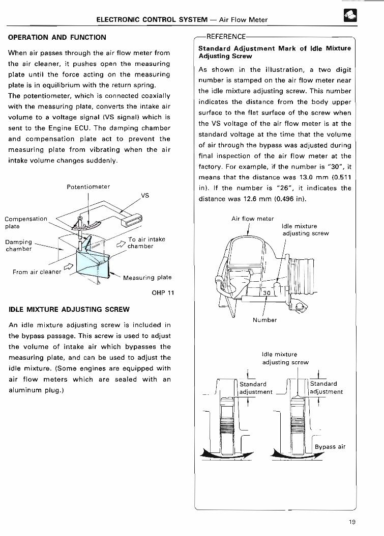
OPERATION AND FUNCTIO N
When air passes through the air flow meter from
the air cleaner, it pushes open the measuring
plate until the force acting on the measuring
plate is in equilibrium with the return spring .
The potentiometer, which is connected coaxially
with the measuring plate, converts the intake air
volume to a voltage signal (VS signal) which is
sent to the Engine ECU . The damping chamber
and compensation plate act to prevent the
measuring plate from vibrating when the air
intake volume changes suddenly .
Potentiometer
OHP 1 1
IDLE MIXTURE ADJUSTING SCREW
An idle mixture adjusting screw is included in
the bypass passage . This screw is used to adjust
the volume of intake air which bypasses the
measuring plate, and can be used to adjust the
idle mixture. (Some engines are equipped with
air flow meters which are sealed with an
aluminum plug .)
®
REFERENCE
Standard Adjustment Mark of Idle MixtureAdjusting Scre w
As shown in the illustration, a two digit
number is stamped on the air flow meter near
the idle mixture adjusting screw. This number
indicates the distance from the body upper
surface to the flat surface of the screw when
the VS voltage of the air flow meter is at the
standard voltage at the time that the volume
of air through the bypass was adjusted during
final inspection of the air flow meter at the
factory. For example, if the number is "30", it
means that the distance was 13.0 mm (0 .511
in) . If the number is "26", it indicates the
distance was 12 .6 mm (0 .496 in) .
Air flow meter
Idle mixtureadjusting screw
Idle mixture
adjusting screw
19

®
VS SIGNAL
ELECTRONIC CONTROL SYSTEM - Air Flow Mete r
There are two types of vane type air flow meter,
which differ in the nature of their electrical
circuitry . In one type, the VS voltage falls when
the air intake volume becomes large and in the
other type, the VS voltage rises when the air
intake volume becomes large .
1 Type 1
The Engine ECU has a built-in constant-voltage
circuit, which supplies a constant 5 V to the VC
terminal of the air flow meter . Consequently,
the output voltage at the VS terminal will
always indicate the exact opening angle of the
measuring plate, and therefore, the exact intake
air volume.
Fuel pump switchPotentiometer
FC E1 E2 VC E2(E1) (FC)
~a~n~a~ff ;o-ts a
v
VS
OHP 12
f 2 ) Type 2
This type of air flow meter is supplied with
ba ttery voltage from the VB terminal .
This type of air flow meter does not have a
constant voltage (5 V) supplied from the Engine
ECU, so the voltage determined by the ratio of
the resistances of the resistor between VB and
VC and the resistor between VC and E2 is input
to the Engine ECU via the VC terminal .
As a result, even when the VS voltage is
affected by fluctuations in the ba ttery voltage,
the Engine ECU, by executing the following
calculation, can detect the intake air volume
accurately:
Intake air volume =
VB - E2 VB - E2(VC - E2) - (VS - E2) VC - VS
For fu rther details, see Step 2, vol . 5 (EFI) .Fuel pump switch Potentiomete
r
Voltage of battery
THA
AVC " E 2
5 .0-i
Voltage (V)
VC H E2
VS H E2
0 1
Measuring plate opening angle
(intake air volume)OHP 1 2
20
Voltage (V)
OHP 1 2
VBHE2
VS H E2
0
Measuring plate opening angl e
(intake air volume) OHP 12

ELECTRONIC CONTROL SYSTEM - Air Flow Meter
2 . OPTICAL KARMAN VORTEX TYPE
This type of air flow meter directly senses the
intake air volume optically. Compared to the
vane type air flow meter, it can be made smaller
and lighter in weight . The simplified construction
of the air passage also reduces inlet resistance .
This air flow meter is constructed as shown in
the following illustration :
Mirror LED Leaf spring
From
W~'M
I To airair moo, Karman ♦ intakecreaner ~9 vn.toYO~ chambe r
Pressure-directin
Mirro r
~ Pressure~ directing ape rture
OHP 1 3
Vortex / ___ . . 9 Phntntrancictn r
generator OHP 1 3
OPERATION AND FUNCTIO N
A pillar (called the "vo rtex generator") placed in
the middle of a uniform flow of air generates a
vortex called a "Karman vo rtex" down-stream
of the pillar .
The frequency "f" of the Karman vortex thus
generated, the velocity of the air "V" and the
diameter of the pillar "d" have the following
relationship :
f - K x d
®
of a piece of thin metal foil (called a "mirror") to
the pressure of the vortexes and optically
detecting the vibrations of the mirror by means
of a photocoupler (an LED combined with a
phototransistor) .
LED
r=^
Phototransisto r
Vortex -generato r
The intake air volume (KS) signal is a pulse
signal like that shown below . When the intake
air volume is low, this signal has a low
frequency. When the intake air volume is high,
this signal has a high frequency .
High
Voltagesigna l
LowLow
Intake air volumeHigh
OHP 1 3
ELECTRICAL CIRCUITR Y
Air flow meter
Pillar (vo rtex generator )
KARMAN VORTEXOHP 1 3
Utilizing this principle, the frequency of the
vortexes generated by the vortex generator is
measured, making it possible to determine the
air flow volume .
Vortexes are detected by subjecting the su rface
Phototransistor
Engine EC U
OHP 13
21

4
3 . HOT-WIRE TYPE
ELECTRONIC CONTROL SYSTEM - Air Flow Meter
Instead of measuring intake air volume in the man-
ner of other air flow meters, a hot-wire type air
flow meter measures intake air mass directly .
The structure is both compact and lightweight . In
addition, there is only a low level of intake
resistance by the sensor .
Having no mechanical functions it offers a
superior durability .
Thermisto r
F~ REFERENCE
A hot-wire type air flow meter as shown below
is used on some models .
OPERATION AND FUNCTION
Current flows to the hot-wire (heater) causing it
to be heated . When air flows through the wire,
the hot-wire is cooled corresponding to the intake
air mass . By controlling the current flowing to the
hot-wire in order to keep the hot-wire temperature
constant, that current becomes proportional to in-
take air mass. Intake air mass can then be
measured by detecting that current . In case of
hot-wire type air flow meters, this current is con-
verted into a voltage that is then output to the
Engine ECU .
Hot-wire (heater) *
*Constant temperature
ThermistorIntake air mass --- (g/sec .)

ELECTRONIC CONTROL SYSTEM - Air Flow Mete r
In an actual air flow meter, a hot-wire is incor-
porated into the bridge circuit . This bridge circuit
has the characteristic of the potentials at points A
and B being equal when the product of resistance
along the diagonal line is equal ([Ra + R3] • R1 =
Rh • R2) . When the hot-wire (Rh) is cooled by in-
take air, resistance decreases resulting in the for-
mation of a difference between the potentials of
points A and B . An operational amplifier detects
this difference and causes a rise in the voltage ap-
plied to the circuit (increases the current flowing
to the hot-wire (Rh)) . When this is done, the
temperature of the hot-wire (Rh) again rises
resulting in a corresponding increase in resistance
until the potentials of points A and B become
equal (the voltages of points A and B become
higher) . By utilizing the properties of this type of
bridge circuit, the air flow meter is able to
measure intake air mass by detecting the voltage
at point B . Moreover, in this system, the
temperature of the hot-wire (Rh) is continuously
maintained at a constant temperature higher than
the temperature of the intake air by using the ther-
mistor (Ra) .
Consequently, since intake air mass can be
measured accurately even if intake air
temperature changes, it is not necessary for the
Engine ECU to correct the fuel injection duration
for the intake air temperature . In addition, when
air density decreases at high altitudes, the cooling
capacity of the air decreases in comparison with
the same intake air volume at sea level . As a
result, the amount of cooling of the hot-wire is
reduced . Since the intake air mass detected will
also decrease the high-altitude compensation cor-
rection is not necessary .
®
Diagram Indicating Principle of Electrical Circuitry
Air flow meter
EngineEC U
REFERENCE
The voltage (V) required to raise the
temperature of the hot-wire (Rh) by the amount
of AT from the intake air temperature remains
constant at all times even if the intake air
temperature changes . In addition, the coolin g
capacity of the air is always proportional to the
intake air mass . Consequently, if the intake air
mass remains the same, the output of the air
flow meter will not change even if there is a
change in intake air temperature .
Hot-wire (Rh) temperature
20°C+ AT --
0°C+OT --
20°C
0°C
vIntake air temperatur e
NOTE
An intake air temperature sensor is not required
for the measurement of intake air mass due to
the properties of a hot-wire type air flow meter .
However, since intake air temperature is re-
quired for other electronic control systems of
the engine, the hot-wire type air flow meter has
the built-in intake air temperature sensor .

ELECTRONIC CONTROL SYSTEM - Throttle Position Senso r
THROTTLE POSITION SENSO R
The throttle position sensor is mounted on the
throttle body . This sensor converts the throttle
opening angle to a voltage and sends it to the
Engine ECU as the thrott le opening angle signal .
The IDL signal is used mainly in fuel cut-off
control and ignition timing corrections and the
VTA or PSW signal is used mainly for increasing
the fuel injection volume to increase engine
output .
There are two types of throttle position sensor,
as follows :
• On-off type
• Linear type
1 . ON-OFF TYPE
This type of throttle position sensor detects
whether the engine is idling or running under a
heavy load by means of the idle (IDL) contact or
power (PSW) contact .
Other terminals or contacts can also be used to
perform other functions, depending on the type
of engine. These include: the lean burn switch
(LSW) contact, for lean burn correction; the L1,
L2, and L3 terminals for control of the ECT ; the
ACC1 and ACC2 terminals for sensing
acceleration ; etc. For further details, see Step 2,
vol . 5 (EFI) .
1 2-contact type
2 3-contact type
3 With L1, L2 and L3 terminal s
IDL
4 With ACC1 and ACC2 terminal s
ACC2
ELECTRICAL CIRCUITRY (2-CONTACT TYPE )
PSW ~
E
IDL
IDL H EOn
Off
PSW H E ' Off~
On
i IThro ttle valve ---) Open
OHP 14
OHP 1 4
22

ELECTRONIC CONTROL SYSTEM - Throttle Position Senso r
2 . LINEAR TYPE
This sensor is composed of two sliders (at the
tips of which are mounted the contacts for the
IDL and VTA signals, respectively) .
A constant 5 V is applied to the VC terminal
from the Engine ECU . As the contact slides along
the resistor in accordance with the throttle valve
opening angle, a voltage is applied to the VTA
terminal in proportion to this angle .
When the throttle valve is closed completely,
the contact for the IDL signal connects the IDL
and E2 terminals .
The VTA and IDL output signals are as shown in
the table below.
Slider (contact forVTA signal)
OHP 1 5
(V)5-12fi
}
Idling
Closed ~- Thrott le valve --~ Open
OHP 15
ELECTRICAL CIRCUITRY
OHP 1 5
*Depending on the model, this circuitry may
include both resistors Ri and R2, Ri only, or R2
only .
NOTE
Recent linear type throttle position sensors in-
clude models without an IDL point and the
model with an IDL point but its terminal is not
connected to the Engine ECU . In these models,
the Engine ECU detects idling condition perfor-
ming learned control by using the VTA signal .
23

0 ELECTRONIC CONTROL SYSTEM - G and NE Signal Generators
G AND NE SIGNAL GENERATOR S
The G and NE signals are generated by the
timing rotors or signal plates and the pickup
coils . These signals are used by the Engine ECU
to detect the crankshaft angle and engine speed .
These signals are very important not only for the
EFI system but also for the ESA system .
The sensors which generate these signals can be
divided into the following three types depending
on their installation position, but their basic
construction and operation are the same :
• In-distributor type
• Cam position sensor type
• Separate type
1 . IN-DISTRIBUTOR TYPE
The conventional governor advance and vacuum
advance mechanisms have been eliminated in
the distributor used with the TCCS engine
control system, since spark advance is controlled
electronically by the Engine ECU . The distributor
in the engine control system contains the timing
rotors and pickup coils for the G and NE signals .
The number of teeth on the rotor and the
number of pickup coils differ depending on the
engine. Below, we will explain the construction
and operation of the G and NE signal generators
that use a single pickup coil and a 4-tooth rotor
for the G signal, and a single pickup coil and 24-
tooth rotor for the NE signal .
G SIGNAL
The G signal informs the Engine ECU of the
standard crankshaft angle, which is used to
determine the injection timing and ignition
timing in relation to the TDC (top dead center) of
each cylinder .
The components of the distributor used to
generate these signals are as follows :
1) The G signal timing rotor, which is fixed to
the distributor shaft and turns once for
every two rotations of the crankshaft .
2) The G pickup coil, which is mounted on the
inside of the distributor housing .
The G signal timing rotor is provided with four
teeth which activate the G pickup coil four times
per each revolution of the distributor shaft,
generating the waveforms shown in the chart
shown below . From these signals, the Engine ECU
detects when each piston is near TDC (ex-
ample : BTDC10°CA*) .
" Depending on engine models .
1 turn of timing roto r
1800 CA (crankshaft angle )
G signal
OHP 1 6
24

ELECTRONIC CONTROL SYSTEM - G and NE Signal Generator s
NE SIGNAL
The NE signal is used by the Engine ECU to
detect the engine speed . NE signals are
generated in the pickup coil by the timing rotor
in the same way as with the G signal . The only
difference is that the timing rotor for the NE
signal has 24 teeth . It activates the NE pickup
coil 24 times per each revolution of the
distributor shaft, generating the waveforms
shown in the chart . From these signals, the
Engine ECU detects the engine speed as well as
each 30° change in the engine crankshaft angle .
NE signal timing rotor
OHP 1 6
NE signal
1/2 turn of timing rotor
ELECTRICAL CIRCUITRY, AND G AND NESIGNAL WAVEFORMS
1 G signal (1 pickup coil, 4 teeth)
NE signal ( 1 pickup coil, 24 teeth )
Engine EC U
NE signal
OHP 171800 CA
OHP 1 7
(2) G signal (1 pickup coil, 2 teeth)
NE signal (1 pickup coil, 24 teeth )
Engine ECU
OHP 1 7
U U rrur 1 r30° CA
rrr
OHP 16G signa l
NE signal
180° CA OHP 17
25

ELECTRONIC CONTROL SYSTEM - G and NE Signal Generator s
3 G1 and G2 signals (2 pickup coils, 1 tooth) 5 G signal (1 pickup coil, 1 tooth)
NE signal (1 pickup coil, 24 teeth )
Engine EC U
OHP 1 8
FG1 signal '~
G2 signal
720° CA
I
NE signal (1 pickup coil, 4 teeth )
Engine ECU
OHP 19
G signa l
NE signa l
NE signalIVU UU
180° CA OHP 18
4 NE signal (1 pickup coil, 4 teeth)
Engine ECU
M1
Igniter
a
-1\
OHP 18
NE signal
180° CA
OHP 18
180 0
6~ NE signal (2 pickup coils, 4 teeth )
Engine EC U
NE signal
180° CA
~
720° CA
OHP 1 9
OHP 1 9
OHP 1 9
This type of circuit has two NE pickup coils
connected in series . This is for the purpose of
preventing noise in the NE signal during
operation of the ignition coil .
26
ELECTRONIC CONTROL SYSTEM - G and NE Signal Generators
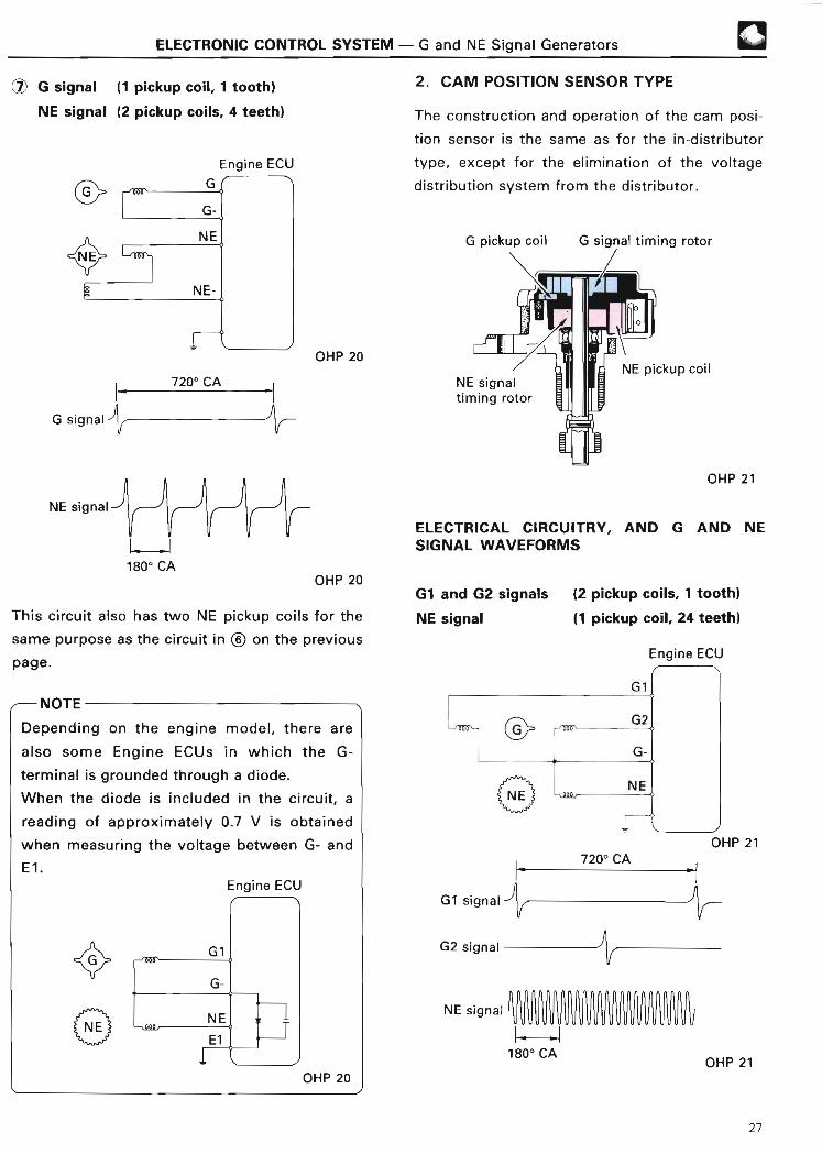
7 G signal (1 pickup coil, 1 tooth)
NE signal (2 pickup coils, 4 teeth )
Engine ECU
2 . CAM POSITION SENSOR TYP E
The construction and operation of the cam posi-
tion sensor is the same as for the in-distributor
type, except for the elimination of the voltage
distribution system from the distributor .
G pickup coil G signal timing rotor
NE signal--'
7200 CA
~. yi1800 CA
j
OHP 2 0
OHP 20
This circuit also has two NE pickup coils for the
same purpose as the circuit in © on the previous
page .
~-- NOTE
Depending on the engine model, there are
also some Engine ECUs in which the G-
terminal is grounded through a diode.
When the diode is included in the circuit, a
reading of approximately 0.7 V is obtained
when measuring the voltage between G- an d
El .Engine ECU
OHP 20
NE signaltiming rotor
NE pickup coil
OHP 2 1
ELECTRICAL CIRCUITRY, AND G AND NESIGNAL WAVEFORM S
G1 and G2 signals (2 pickup coils, 1 tooth)
NE signal (1 pickup coil, 24 teeth )
Engine ECU
Gl f
Lml-
G1 signa l
G2 signal -
NE signal 11--.11800 CA
G2
NE I
OHP 2 1
720° CA
VOHP 21
27

a ELECTRONIC CONTROL SYSTEM - G and NE Signal Generator s
3 . SEPARATE TYPE
Compared to the other types, the separate type
G and NE signal generator differs in the sensor
installation position, as shown in the following
illustration . However, the basic function is the
same.
G pickupcoil (G2)
G pickupcoil (G1 )
NE pickup coil
OHP 22
Rotation of the G signal plate on the camshaft
and the NE signal plate on the crankshaft alters
the air gap between the projection(s) of the
plate and the G pickup coil and the NE pickup
coil . The change in the gap generates an
electromotive force in the pickup coil . This
creates the G and NE signals .
L I IIIIIII Illr .,d,l,„JL~ _
I
G PICKUP COI L
NE PICKUP COIL
G SIGNAL
The G1 signal informs the Engine ECU of the
standard crankshaft angle, which is used to
determine the injection timing and ignition
timing in relation to compression TDC of cylinder
No . 6. The G2 signal conveys the same
information for cylinder No . 1 .
The sensors that generate these signals consist
of a signal plate, which is fixed to the camshaft
timing pulley and turns once per every two
rotations of the crankshaft; and a pickup coil for
the G signal, which is fitted to the distributor
housing .
The G signal plate is provided with a projection
which activates the G pickup coil once per each
rotation of the camshaft, generating waveforms
like those shown in the following chart . From
these signals, the Engine ECU detects when the
No . 6 and No . 1 pistons are near their
compression TDC .
Camshaft timingpulley
G1 signa l
G2 signal
A
G pickup coi l
3600 CA
NNo . 1 cylindernear TDCcompression
Camshaft
OHP 22
No. 6 cylindernear TDCcompressio n
OHP 22
No . 6 cylindernear TDCcompression
28

ELECTRONIC CONTROL SYSTEM - G and NE Signal Generators
NE SIGNAL
F*1ELECTRICAL CIRCUITRY, AND G AND NESIGNAL WAVEFORMS
The NE signal is used by the Engine ECU to
detect the engine speed . The Engine EC U
determines the basic injection duration and basic G1 signal (1 pickup coil, 1 tooth)
ignition advance angle by these signals . NE G2 signal (1 pickup coil, 1 tooth)
signals are generated in the NE pickup coil by NE signal ( 1 pickup coil, 12 teeth )
the NE signal plate like the G signals . The only
difference is that the signal plate for the NE
signal has 12 teeth instead of just one .
Therefore, 12 NE signals are generated per each
engine revolution .
From these signals, the Engine ECU detects the
engine speed as well as each 30° change in the
crankshaft angle .
Engine ECU
OHP 23
NE pickup coil
rfimmimlii~
OHP 22
One rotation of NE signal plat e
NE signal
h I 1
~r~rrur~ ri ~► - 30° CA
irr
OHP 22
FG1 signa l
G2 signa l
NE signal
1800 CA
7200 CA
J
OHP 23
29

❑ ELECTRONIC CONTROL SYSTEM - G and NE Signal Generator s
© G signal (1 pickup coil, 1 tooth)
NE signal (1 pickup coil, 36 minus 2 teeth )
Engine ECU
e~N(NE
This type of NE signal is able to detect both
engine speed and crankshaft angle at the portion
of two teeth missing . It is unable, however, to
distinguish between the TDC of the compression
stroke and that of the exhaust stroke . The G
signal is used for this purpose .
,,-- REFERENC E
4A-FE engine which applies the Engine ECU
made by Bosch uses G signal generator of the
hall element type .
Holl element will generate electromotive force
in proportion to the changes of the magnetic
flux .
I
G signa l
NE signalYYVV W Y
720°CA
360°CA
V_I L --I L10°CA 30°CA
7
VVVYYVYYVVYVVY YtlYYVVVYYVYYYVVVYVYYYVYVYVYtlYYYY YVVVVYtlVVYVVY
/
NOTE
The G signal timing rotor of the above described type in Z) is integrated into a single unit with the cam-
shaft, while the NE signal timing rotor is integrated into a single unit with the crankshaft timing pulley .
Also, the G signal generator is located in the distributor depending on the engine models .
Camshaft
A~B R A A ~ a 0 ~ I
G pickup coi l
Cylinder head
NE signal timing rotor

ELECTRONIC CONTROL SYSTEM- Water Temperature Sensor,
Intake Air Temperature Sensor ®
WATER TEMPERATURE INTAKE AIR TEMPERATURESENSOR SENSOR
This sensor detects the coolant temperature by This sensor detects the temperature of the
means of an internal thermistor . intake air by means of an internal thermistor .
~
Thermistor
OHP 24
,4) For L-type EF I
(vane type )
-20 0 20 40 60 80 100 120(-4) (32) (68)(104)(140)(176)(212) ( 248)
Temperature °C (°F) OHP 24
ELECTRICAL CIRCUITRY
Engine ECU
Thermisto r
(1) For D-type EF I
(optical Karman vortex type )
Air flow mete r
Water temperaturesensor(intake air temperature sensor)
OHP 24
OHP 25
Intake airtemp. sensor
OHP 25
30

®
(hot-wire type)
Intake Air Temperature Sensor,ELECTRONIC CONTROL SYSTEM - Oxygen Sensor (Oz Sensor )
ELECTRICAL CIRCUITR Y
The electrical circuitry of the intake air
temperature sensor is basically the same as that
of the water temperature sensor . See the
diagram for the electrical circuitry of the water
temperature sensor .
OXYGEN SENSOR (02 SENSOR )
In order for engines equipped with the TWC(three-way catalytic converter) to achieve thebest purification performance, it is necessary forthe air-fuel ratio to be kept within a narrowrange near the theoretical (stoichiometric) air-fuel ratio .
The oxygen sensor senses whether the air-fuelratio is richer or leaner than the theoretical air-fuel ratio . It is located in the exhaust manifold,in the front exhaust pipe, etc . (This differsdepending on the engine model . )
The following types of oxygen sensor are used ;
they differ mainly in the material used for the
element :
• Zirconia element type• Titania element typ e
1 . ZIRCONIA ELEMENT TYP E
This oxygen sensor consists of a element madeof zirconium dioxide (Zr02, a kind of ceramic) .This element is coated on both the inside andoutside with a thin layer of platinum. Ambientair is introduced into the inside of the sensor,and the outside of the sensor is exposed toexhaust gases .
I Flang e
= Platinum
L- Zirconia element
Platinu m
Protectivecover

ELECTRONIC CONTROL SYSTEM - Oxygen Sensor (02 Sensor )
OPERATION
If the oxygen concentration on the inside surfaceof the zirconia element differs greatly from thaton the outside surface at high temperatures(400°C [752°F] or higher), the zirconia elementgenerates a voltage, which acts as an OX signal
to the Engine ECU, keeping it informed at alltimes about the concentration of oxygen in theexhaust gas .
When the air-fuel mixture is lean, there is a lotof oxygen in the exhaust gas, so there is littledifference between the oxygen concentrationinside and outside the sensor element . For thisreason, the voltage generated by the zirconiaelement is low (close to 0 V) . Conversely, if theair-fuel mixture is rich, the oxygen in theexhaust gas almost disappears . This creates a
large difference in the oxygen concentrationsinside and outside the sensor, so the voltagegenerated by the zirconia element is compara-tively large (approximately 1 V) .
Theoretical
air-fuel ratio
®
,,-- NOTE
Even if the oxygen sensor is normal, if the out-
side of the oxygen sensor is contaminated with
mud, etc ., it could prevent outside air from get-
ting into the oxygen sensor . The difference bet-
ween the oxygen concentrations in the outside
air and the exhaust gas will fall, so the oxygen
sensor will always be sending a lean signal to
the ECU .
ELECTRICAL CIRCUITRY
Engine ECU
Oxygensensor
OHP 26
>
m
M No air Much airo into into> exhaustga exhaustgas.. .DCL
O
i\
0Richer Air-fuel Leaner OHP 26(no air) ratio (much air )
The platinum (with which the element is coated)operates as a catalyst, causing the oxygen andthe CO (carbon monoxide) in the exhaust gas toreact with each other. This decreases theoxygen volume and increases the sensitivity ofthe sensor .Based on the signal output by this sensor, theEngine ECU increases or reduces the injectionvolume to keep the air-fuel ratio at a constantvalue near the theoretical air-fuel ratio .Some zirconia oxygen sensors are provided witha heater which heats the zirconia element. Theheater is also controlled by the ECU . When theintake air volume is low (that is, when thetemperature of the exhaust gas is low), currentflows to the heater to heat the sensor .For further details, see page 114 .
31

ELECTRONIC CONTROL SYSTEM - Oxygen Sensor (02 Sensor )
2. TITANIA ELEMENT TYPE
This oxygen sensor consists of a semiconductor
element made of titanium dioxide (Ti02, which
is, like Zr02, a kind of ceramic) . This sensor uses
a thick film type titania element formed on the
front end of a laminated substrate to detect the
oxygen concentration in the exhaust gas .
Protectivecover
OHP 27
OPERATION
The properties of titania are such that its
resistance changes in accordance with the
oxygen concentration of the exhaust gas . This
resistance changes abruptly at the boundary
between a lean and a rich theoretical air-fuel
ratio, as shown in the following graph . The
resistance of titania also changes greatly in
response to changes in temperature. A heater is
therefore built into the laminated substrate to
keep the temperature of the element constant .
xT
Theoretical8i air-fuel rati o
~U
V
No airintoexhaust gass
Much airintoexhaustgass
Richer a Air-fuel c* Leaner(no air) ratio ( much air) OHP 27
This sensor is connected to the Engine ECU, as
shown in the following circuit diagram. A 1V
potential is supplied at all times to the OX ±i
terminal by the Engine ECU . The Engine ECU has
a built-in comparator* which compares the
voltage drop at the OX terminal (due to the
change in resistance of the titania) to a
reference voltage (0 .45 V). If the result shows
that the OX voltage is greater than 0 .45 V (that
is, if the oxygen sensor resistance is low), the
Engine ECU judges that the air-fuel ratio is rich .
If the OX voltage is lower than 0 .45 V (oxygen
sensor resistance high), it judges that the air-
fuel ratio is lean .*See page 37 for details on the comparator .
ELECTRICAL CIRCUITRY
Engine ECU
Check
connector
OX~+
OX
OHP 2 7
1 V
0.45 V
32

ELECTRONIC CONTROL SYSTEM - Lean Mixture Senso r
LEAN MIXTURE SENSOR
The lean mixture sensor is constructed inbasically the same way as the zirconia elementtype oxygen sensor, but its use differs .
Theoretical
air-fuel ratio
Engine EC U
Heate r
Protectivecover
OPERATIONThe zirconia element type oxygen sensoroperates on the principle that a voltage will begenerated if the difference in the oxygenconcentration inside and outside the sensor isgreat .
In the lean mixture sensor, however, a voltageapplied to the zirconia element when thetemperature is high (650°C [1202°F] or greater),results in a current flow with a value which isproportional to the oxygen concentration in the
exhaust gas .
In other words, when the air-fuel mixture is rich,there will be no oxygen in the exhaust gas, sono current will flow through the zirconia
element. When the air-fuel mixture is lean, on
the other hand, there will be a lot of oxygen inthe exhaust gas and the amount of currentflowing through the zirconia element will belarge, as shown in the following graph .
The lean mixture sensor has been adopted toassure that the air-fuel ratio is kept within apredetermined range, thereby improving fueleconomy as well as drivability .
This sensor also comes with a heater to heat the
zirconia element . The heater is controlled in the
same way as the heater of the oxygen sensor .
For further details, see page 114 .
ELECTRICAL CIRCUITR Y
Lean
mixturesensor
OHP 28
REFERENCE
When the air-fuel mixture is extremely lean(about 20:1), combustion will be accompaniedby reductions in NOx (oxides of nitrogen), CO,and HC (hydrocarbon gas), as shown in the
graph below . This is a good thing up to a
point . However, if the air-fuel mixture is toolean, not only will HC concentrations
increase, but the engine will lose power
and/or misfire .
CO HC(%) I (PPM
12 ~
8 d
4
600
400
20 0
0
\ \HC\
\ \~
CO\
\
NOx
❑
NOx
(PPM)
300 0
2000
1000
10 12 14 16 18 20 220
Richer-Air-fuel ratio~Leaner
OHP 28
33

ELECTRONIC CONTROL SYSTEM - Vehicle Speed Senso r
VEHICLE SPEED SENSOR
This sensor senses the actual speed at which the
vehicle is traveling . It outputs an SPD signal,
which is used mainly to control the ISC system,
and to control the air-fuel ratio during
acceleration, deceleration, etc .
There are four types of speed sensor :
• Reed switch type
• Photocoupler typ e
• Electromagnetic pickup typ e
• MRE (magnetic resistance element) typ e
1 . REED SWITCH TYP E
This sensor is mounted in the analog
combination meter. It contains a magnet which
is rotated by the speedometer cable, turning the
reed switch on and off. The reed switch goes on
and off four times each time the speedometer
cable rotates once .
The magnet has the polarities shown in the
figure below. The magnetic force at the four
areas of transition between the N and S poles of
the magnet opens and closes the contacts of the
reed switch as the magnet rotates .
Q To speedometer cabl e
OHP 29
ELECTRICAL CIRCUITRYEngine ECU
2 . PHOTOCOUPLER TYPE
This sensor is mounted in the combination
meter. It includes a photocoupler made from an
LED, which is aimed at a phototransistor . The
LED and phototransistor are separated by a
slotted wheel, which is driven by the
speedometer cable . The slots in the slotted
wheel generate light pulses as the wheel turns,
with the light emitted by the LED divided into 20
pulses for each revolution of the cable . These 20
pulses are converted to four pulses by the digital
meter computer, then sent as signals to the ECU .
Slo ttedwheel
OHP 29
ELECTRICAL CIRCUITR Y
+B
Combinationmeter Pulse
Phototransistor
conversio ncircuit
Engine EC U
OHP 29
34 OHP 29

ELECTRONIC CONTROL SYSTEM - Vehicle Speed Senso r
3 . ELECTROMAGNETIC PICKUP TYP E
This sensor is fitted to the transmission and
detects the rotational speed of the transmission
output shaft .This sensor consists of a permanent magnet, a
coil, and a core. A rotor with four teeth is
mounted on the transmission output shaft .
Rotor
N S i Magnet
OHP 3 0
+V
OHP 30
0
-V
ELECTRICAL CIRCUITRY
OHP 3 0
Engine ECU
OHP 3 0
OPERATION
When the transmission output shaft rotates, the
distance between the core of the coil and the
rotor increases and decreases because of the
teeth .
The number of lines of magnetic force passing
through the core increases or decreases
accordingly, and AC (alternating current) voltage
is generated in the coil .
Since the frequency of this AC voltage is
proportional to the rotational speed of the rotor,
it can be used to detect the vehicle speed .
OHP 3 0
®
Coil Core Speed sensor
35

F* ELECTRONIC CONTROL SYSTEM - Vehicle Speed Senso r
4 . MRE (MAGNETIC RESISTANCEELEMENT) TYPE
This sensor is mounted on the transmission or
the transfer and is driven by the drive gear of
the output shaft .
Speed sensor OHP 3 1
This sensor consists of an HIC (hybrid integrated
circuit) with a built-in MRE (magnetic resistance
element) and a magnetic ring .
OHP 3 1
OPERATION
The resistance value of the MRE changes accor-
ding to the direction of the lines of magnetic force
applied to it .
Thus, the direction of the lines of magnetic force
is changed by the rotation of the magnet fitted to
the magnetic ring with the result that the output
of the MRE becomes an alternating waveform as
shown in the illustration on the above right .
The comparator in the speed sensor converts the
alternating waveform into a digital signal, which
is then inverted by the transistor before being
sent to the combination meter, as shown in the
illustration at right above .
The frequency of the waveform is in accordance
with the number of poles of the magnet fitted to
the magnetic ring . There are two types of
magnetic ring (depending on the vehicle model) :
the type with twenty magnetic poles, and the
type with four magnetic poles . The 20-pole type
generates a 20-cycle waveform (i .e., twenty
pulses for each rotation of the magnetic ring),
while the 4-pole type generates a 4-cycle
waveform .Constant voltage circuit , + B
20-POLE TYPE SPEED SENSO R
Magnetic ring(rotating )
MRE output
N S N
Comparator 1output 0
Speed 12 V~sensor 0 Voutput
OHP 3 1
In the 20-pole type, the frequency of the digital
signal is converted from twenty pulses for each
revolution of the magnetic ring to four pulses by
the pulse conversion circuit in the combination
meter, then the signal is sent to the Engine ECU .
(See electrical circuitry at right . )
In the case of the 4-pole type, there are two
different kinds: in one type, the signal from the
speed sensor passes through the combination
meter before going to the Engine ECU ; in the
other type, this signal goes directly to the
Engine ECU without passing through the
combination meter. (See electrical circuitry at
right . )
36

ELECTRONIC CONTROL SYSTEM - Vehicle Speed Senso r
The output circuitry of the speed sensor differs
depending on the vehicle model . As a result, the
output signal also differs depending on the
model : one type is the output voltage type and
the other is the variable resistance type .
The types of MRE-type speed sensor presently
used by Toyota are shown in the following table .
(As of Mar., 1991 )
TYPE OF TYPE OF SIGNALMAGNETIC RIN G
C 20-pole type(20 pulses/rev .) Output voltage typ e
5-12V)(0V H
4-pole type30, (4 pulses/rev .) Variable resistanc e
type (0 12 H -)
REFERENCE
Comparator
The comparator circuit selects either of the
two input voltages as the reference voltage
and then compares the reference voltage with
the other input voltage to judge which is
larger or smaller. If input voltage 'B` is taken
as the reference voltage in the example
circuit shown below, the relationship between
the input and the output becomes as follows :
Output
OHP 32
INPUT OUTPUT
A> B Hi (1 )
A < B Lo (0 )
OHP 3 2
The speed sensor uses this function to convert
the alternating waveform into a digital signal :
1
OHP 32
ELECTRICAL CIRCUITRY
-11-` 20-pole type ( output voltage type)
®
20 pulses 4 pulses Engine ECU
Speed Combination nsensor 111111111111 mete r
4-pole type (output voltage type )
4 pulses 4 pulsesSpeed Combinatio nsensor -1 LJL meter
Input circui t
C 4-pole type (variable resistance type)
OHP 33
Engine ECU
OHP 3 3
OHP 3 3
37

ELECTRONIC CONTROL SYSTEM - STA Signal, NSW Signa l
STA (STARTER) SIGNA L
This signal is used to judge if the engine is being
cranked . Its main function is to allow the Engine
ECU to increase the fuel injection volume during
cranking. As can be understood from the figure
below, the STA signal is voltage the same
voltage as that supplied to the starter motor .
ELECTRICAL CIRCUITRY
Ignition (M/T)switch
Engine ECU
OHP 34
NSW (NEUTRAL STARTSWITCH) SIGNAL
In vehicles with an automatic transmission or
transaxle, this signal is used by the Engine ECU
to determine whether the shift lever is in the
"P" or "N" position, or in some other position .
The NSW signal is used mainly in controlling the
ISC system .
ELECTRICAL CIRCUITRY
Engine ECU
OHP 34
REFERENCE
1 . The Engine ECU judges whether the
engine is cranking based on the STA
signal. There are also engines which use
the NE signal to judge the engine running
conditions during starting .
2 . In some engine models, if the STA signal
is input while the engine is running, it
could result in the engine stalling .
1 . When the ignition switch is in the START
position, ba ttery voltage is supplied to the
NSW terminal .
2 . When the ignition switch is in a position
other than START, and the neutral sta rt
switch is open ( i .e ., the transmission is in
"L", "2", "D" or "R"), the voltage at the
NSW terminal is high .
3 . When the ignition switch is in a position
other than START, and the neutral sta rt
switch is closed (i .e ., the transmission is in
"P" or " N"), the voltage at the NSW
terminal is low due to the electrical load
at the sta rter motor, etc .
38

ELECTRONIC CONTROL SYSTEM - A/C Signal, Electrical Load Signa l
A/C (AIR CONDITIONER)SIGNAL
This signal senses when the air conditioner
magnetic clutch is on or air conditioner switch is on .
This signal is used to control the ignition timing
during idling, and to control the ISC system, the
fuel cut-off speed, and other functions .
ELECTRICAL CIRCUITRY
Engine ECU
ELECTRICAL LOAD SIGNAL
1*
This signal detects when the head lamps, rear
window defogger, etc., are on .
Depending on the vehicle model, the circuitry for
this signal can have a number of electrical load
signals which are brought together and input
into the Engine ECU as a single signal, as shown
in the following electrical circuit, or it can have
each signal input to the Engine ECU separately .
This signal is used for control of the ISC system .
ELECTRICAL CIRCUITR Y
A/Cmagneticclutch
C
OHP 34
A/Camplifie r
A/Cswitch
0A/C
Engine ECU
Engine EC U
OHP 34
39
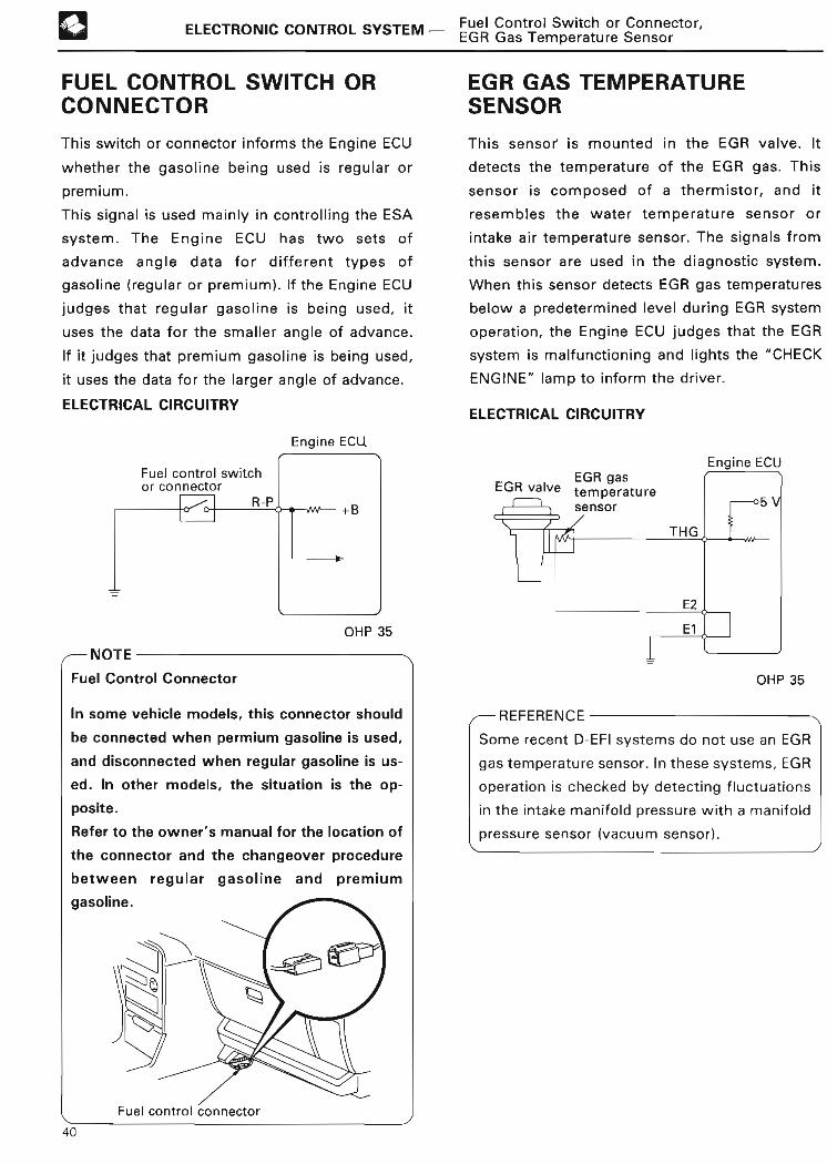
13 ELECTRONIC CONTROL SYSTEM - Fuel Control Switch or Connector,EGR Gas Temperature Senso r
FUEL CONTROL SWITCH ORCONNECTOR
EGR GAS TEMPERATURESENSOR
This switch or connector informs the Engine ECU
whether the gasoline being used is regular or
premium .
This signal is used mainly in controlling the ESA
system . The Engine ECU has two sets of
advance angle data for different types of
gasoline (regular or premium) . If the Engine ECU
judges that regular gasoline is being used, it
uses the data for the smaller angle of advance .
If it judges that premium gasoline is being used,
it uses the data for the larger angle of advance .
ELECTRICAL CIRCUITRY
Engine ECU
This sensor is mounted in the EGR valve . It
detects the temperature of the EGR gas. This
sensor is composed of a thermistor, and it
resembles the water temperature sensor or
intake air temperature sensor . The signals from
this sensor are used in the diagnostic system .
When this sensor detects EGR gas temperatures
below a predetermined level during EGR system
operation, the Engine ECU judges that the EGR
system is malfunctioning and lights the "CHECK
ENGINE" lamp to inform the driver .
ELECTRICAL CIRCUITRY
Engine ECU
OHP 35
INOTE
Fuel Control Connecto r
In some vehicle models, this connector should
be connected when permium gasoline is used,
and disconnected when regular gasoline is us-
ed . In other models, the situation is the op-
posite .
Refer to the owner's manual for the location of
the connector and the changeover procedure
between regular gasoline and premiu m
gasoline .
Fuel control connector
OHP 35
REFERENCE
Some recent D-EFI systems do not use an EGR
gas temperature sensor . In these systems, EGR
operation is checked by detecting fluctuations
in the intake manifold pressure with a manifold
pressure sensor (vacuum sensor) .\1
40

ELECTRONIC CONTROL SYSTEM - Variable Resisto r
VARIABLE RESISTO R
This resistor is provided in D-type EFI systems and
L-type EFI with optical Karman vortex type air
flow meter or hot-wire type air flow meter which
are not equipped with an oxygen sensor . It is used
to change the air-fuel ratio of the idle mixture .
OHP 35
Turning the idle mixture adjusting screw
clockwise moves the contacts inside the resistor,
raising the VAF terminal voltage . Conversely,
turning the screw counterclockwise lowers the
VAF terminal voltage .
When the VAF terminal voltage rises, the Engine
ECU increases the injection volume slightly,
making the air-fuel mixture a little richer .
ELECTRICAL CIRCUITRY
Engine ECU
OHP 35
®
NOTE
It is usually not necessa ry to adjust the idle
mixture in most models, provided that the
vehicle is in good condition . However, if it
does become necessary to do so, always use
a CO meter. If a CO meter is not available, it
is best not to attempt to adjust the idle
mixture if at all possible .
1
1 . In the vane type air flow meter, the idle mix-
ture can be adjusted by turning the idle mix-
ture adjusting screw in the air flow meter .
(Some engines are equipped with air flow
meters which are sealed with an aluminum
plug . )
REFERENCE
Idle mixtureadjusting screw
In D-type EFI systems and L-type EFI with
optical Karman vortex type air flow meter
or hot-wire type air flow meter with an ox-
ygen sensor, the ECU uses the signals from
the oxygen sensor to correct the air-fuel
ratio of the idle muxture, so there is no
separate device for adjusting the idle mix-
ture .
41

13ELECTRONIC CONTROL SYSTEM - Kick-down Switch ,
Water Temp . Switch, Clutch Switc h
KICK-DOWN SWITCH* WATER TEMPERATUR E
The kick-down switch is fitted to the floor panelSWITC H
directly under the accelerator pedal . When the This switch sends signals to the Engine ECU
accelerator pedal is depressed beyond the full when the engine is about to overheat . When the
throttle opening level, the kick-down switch Engine ECU receives this signal, it controls the
turns on and sends a KD signal to the ECU . This EFI system and air conditioner cut-off control
KD signal is used for power enrichment. system in order to lower the fuel combustion
*This switch is also called the "full throttle
switch" in other manuals .
~- -~
temperature.
ELECTRICAL CIRCUITRY
Engine EC U
Accelerato r
e----peda l
Kick-down switch OHP 36
ACCELE- Kick-dow nRATOR
switc h
PEDAL
~ .r
Accelerato r
ITEM peda l
THROTTLE Fully Fully FullyVALVE closed opened opened
KICK-DOWNSWITCH Off Off On
OHP 3 6
CLUTCH SWITCH
The clutch switch is located under the clutch
pedal, and is used to detect whether or not the
clutch has been applied . This signal is used
mainly to control the fuel cut-off engine speed
(See page 78), thereby reducing emissions .
ELECTRICAL CIRCUITRY
Engine ECU
ELECTRICAL CIRCUITRY
Engine ECU
OHP 3 6
OHP 3 6
42

ELECTRONIC CONTROL SYSTEM - Knock Senso r
KNOCK SENSOR
The knock sensor is mounted on the cylinder
block and detects knocking in the engine .
Low- Frequency - High
ELECTRICAL CIRCUITRYOHP 37
Engine ECUOHP 37
When engine knocking occurs, the Engine ECU
uses the KNK signal to retard the ignition timing
in order to prevent the knocking .
This sensor contains a piezoelectric element
which generates a voltage when it becomes
deformed as a result of cylinder block vibration
due to knocking .
Diaphrag m
AM l
Piezoelectric element
OHP 37
Since the engine knocks at a frequency of
approximately 7 kHz, the voltage output by the
knock sensor is at its highest level at about that
frequency .
There are two types of knock sensor . One type
generates high voltages over a narrow range of
vibration frequencies, while the other type
generates high voltages over a wide range of
vibration frequencies .
OHP 37
REFERENCE
The Engine ECU judges whether the engine is
knocking by measuring whether the KNK
signal voltage has peaked above a certain
voltage level or not . When the Engine ECU
judges that the engine is knocking, it retards
the ignition timing . When the knocking stops,
the ignition timing is advanced again after a
predetermined period of time .
Strong
Ignition
Weak
Ignition
KNK SIGNAL
Time-
43

ELECTRONIC CONTROL SYSTEM - HAC Sensor, Vapor Pressure Sensor,Turbocharging Pressure Senso r
HAC (HIGH-ALTITUDECOMPENSATION) SENSOR
The HAC sensor senses changes in the at-
mospheric pressure . Its construction and opera-
tion are the same as those of the manifold
pressure sensor (See page 17) .
This sensor can be mounted either in the Engine
ECU, or in the passenger compartment separately
from the Engine ECU . Currently, the type
mounted in the Engine ECU is used the most .
When driving at high altitudes, there is not only a
decrease in the atmospheric pressure, but also a
drop in the density of the intake air . As a result,
the air-fuel ratio deviates toward the rich side in
engines with L-type EFI (excluding hot-wire type
air flow meters) . The HAC sensor corrects for
these deviations in the air-fuel ratio .
ELECTRICAL CIRCUITR Y(type with sensor mounted separately )
HAC sensor Engine ECU
TURBOCHARGING PRESSURESENSO R
The turbocharging pressure sensor senses the
turbocharging pressure ( intake manifold
pressure) . Its construction and operation are the
same as those of the manifold pressure sensor
(See page 17) .
If the turbocharging pressure becomes
abnormally high, the Engine ECU cuts off the
supply of fuel to protect the engine .
Silicon chi p
f intake manifold pressureOHP 38
(V)
5
4
3
t Atmospheric pressure OHP 38
VAPOR PRESSURE SENSO R
Basic operation and construction is the same as
that of a manifold pressure sensor or turbocharg-
ing pressure sensor . Output characteristics differ,
however, to enable the detection of small
changes in vapor pressure .
(V )
44
5
4
3
2
1 k0 1
-3 . 5(-26)
Atmospheric pressur e
0 +1 .5(0) (+11)
Pressure
kPa
(mmHg)
2
1
0 13 100 200 kPa(100, 3 .9) (750, 29 .5) (1500, 59.1) (mmHg, in .Hg)
Turbocharging pressure (absolute pressure)
OHP 38
ELECTRICAL CIRCUITRY
Turbochargingpressure sensor Engine ECU

ELECTRONIC CONTROL SYSTEM- Stop Lamp Switch, Oil Pressure Switch,
Communications Signal s
STOP LAMP SWITC H
This signal is used to detect when the brakes
have been applied . The STP signal voltage is the
same as the voltage supplied to the stop lamps,
as seen in the diagram below .
The STP signal is used mainly to control the fuel
cut-off engine speed . (The fuel cut-off engine
speed is reduced slightly when the vehicle is
braking . )
ELECTRICAL CIRCUITR Y
~Stop lampswitch
STP or BR K
Lamp failure;relay'
- -
Engine ECU
Stop lamps L _____J* Some vehicle models only
OHP 3 9
OIL PRESSURE SWITC H
This signal is used to judge whether the engine
oil pressure is low or high . The oil pressure
signal is used mainly in controlling the ISC
system .
ELECTRICAL CIRCUITRY
COMMUNICATIONS SIGNALS
©
Communications signals are signals that are sent
between different ECUs to make it possible for
them to coordinate their operations .
These communications signals are explained
below .
1 . THROTTLE OPENING ANGLE SIGNAL S
The throttle opening angle (VTA) signal from the
throttle position sensor is processed by the
Engine ECU, then sent to the ECT ECU,
Suspension ECU, etc ., as combinations of the L1,
L2, and L3 signals .
ELECTRICAL CIRCUITR Y
ECT ECU Engine ECU
OHP 39
2 . THROTTLE OPENING ANGLE SIGNALSFOR TRC (TRACTION CONTROL)SYSTEM
These signals are the throttle opening angle
(VTA1 and VTA2) signals which are input from
the main and sub thro ttle position sensors, then
passed on by the Engine ECU to the TRC ECU .
ELECTRICAL CIRCUITRY
TRC ECU Engine EC U
VTH VTH
VSH VSH
01VTA 1
OHP 39
45

ELECTRONIC CONTROL SYSTEM - Communications Signal s
3 . CRUISE CONTROL SYSTEMCOMMUNICATIONS SIGNA L
This signal is the ignition timing retard request
signal that is sent from the Cruise Control ECU
to the Engine ECU .
ELECTRICAL CIRCUITRY
OHP 40
4 . TRC SYSTEM COMMUNICATIONSSIGNAL
This signal is sent from the TRC ECU to the
Engine ECU to inform it that traction control is in
operation . When the TRC ECU outputs the TR
signal, the Engine ECU executes various types of
corrections related to traction control, such as
retarding the ignition timing .
ELECTRICAL CIRCUITR Y
TRC ECU Engine EC U
OHP 40
5 . ABS (ANTI-LOCK BRAKE SYSTEM)COMMUNICATIONS SIGNA L
This signal detects when the ABS system is
operating . It is used in fuel cut-off control to
reduce the effectiveness of engine braking as
necessary .
ELECTRICAL CIRCUITR Y
ABS ECU Engine EC U
OHP 4 0
6. INTERCOOLER SYSTEM WARNINGSIGNAL
When trouble occurs in the intercooler system in
vehicles equipped with a turbocharging system
having a water-cooled type intercooler, the
Intercooler ECU sends this signal to the Engine
ECU, which lights the "CHECK ENGINE" lamp .
ELECTRICAL CIRCUITR Y
IntercoolerECU Engine EC U
OHP 40
46

ELECTRONIC CONTROL SYSTEM - Communications Signal s
7 . EHPS (ELECTRO-HYDRAULIC POWERSTEERING) SYSTEM COMMUNICA-TIONS SIGNAL
When the engine coolant temperature or the
engine speed is extremely low, the load on the
alternator could become excessive when the
vane pump motor of the EHPS is driven .
To prevent this, the Power Steering ECU sends
this signal to the Engine ECU, which therefore
causes the ISC to increase the engine speed .
ELECTRICAL CIRCUITR Y
Power Steering ECU Engine EC U
OHP 4 1
REFERENCE
EHPS is a type of power steering in which the
vane pump is driven by an electric motor .
8 . ENGINE SPEED SIGNAL
This is the NE signal, which is input to the
Engine ECU, then undergoes waveform shaping
and is output to the TRC ECU, etc .
ELECTRICAL CIRCUITR Y
TRC ECU Engine ECU
OHP 41
9 . ENGINE IMMOBILISER SYSTEM COM-MUNICATIONS SIGNA L
The Engine ECU generates a rolling code based on
certain parameters, and sends it to the
Transponder Key ECU ( IMO terminal) .
Upon receiving the rolling code from the Engine
ECU, the Transponder Key ECU converts the roll-
ing code according to certain parameters, and
sends it to the Engine ECU (IMI terminal) .
If the correct signal is not sent by the Transponder
Key ECU, the Engine ECU will prohibit fuel injec-
tion and IGT signal, thus disabling the engine .
ELECTRICAL CIRCUITR Y
Transponder
Key ECU
EFII IMO
Engine ECU
EFIO IMI
47

ELECTRONIC CONTROL SYSTEM - Diagnostic Terminal (S )
DIAGNOSTIC TERMINAL(S )The T or TE1 terminal is located in the checkconnector in the engine compartment and theTE1 and TE2 terminals are located in the TDCL(Toyota diagnostic communication link) in thepassenger compartment ( located under theinstrument panel) .
I Check connecto r
,
OHP 41
NOTE
OBD-II compatible engines of vehicles sold in
the U .S.A . and Canada are equipped with a
DLC3 in addition to the check connector
(DLC1 ; Data Link Connector 1) and TDCL
(DLC2) . Consequently, it does not have a TE2
terminal of DLC1 or TE2 or TE1 terminal of
DLC2 . In addition, in case of reading diagnostic
codes, the tester for exclusive use* must be
connected to DLC3 .
For further details, see page 137-2 .
OBD-II scan tool or TOYOTA hand-hel d
teste r
TDCL
OHP 4 1
When these terminals are connected with the E1terminal, diagnostic codes for either the normalmode or the test mode can be read from theblinking of the "CHECK ENGINE" lamp in thecombination meter. For fu rther details, see page159 .
ELECTRICAL CIRCUITRY
Check connecto r
ElEngine ECU
OHP 4 1
REFERENCE
1 . The TDCL is provided in some vehicl emodels equipped with the TCCS typeengine control system .
2 . In some vehicle models, the TE2 terminalis located in the check connector .
DLC 3
ELECTRICAL CIRCUITR Y
48
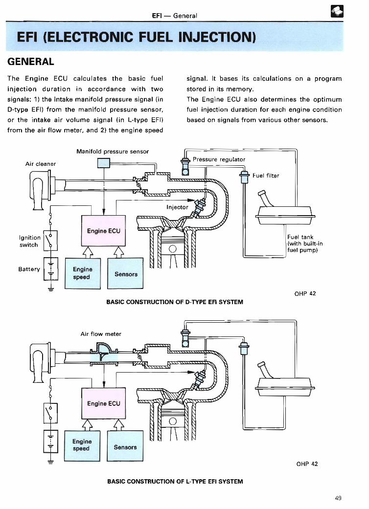
EFI - Genera l
EFI (ELECTRONIC FUEL INJECTION )
GENERAL
The Engine ECU calculates the basic fuel signal . It bases its calculations on a program
injection duration in accordance with two stored in its memo ry .
signals : 1) the intake manifold pressure signal (in The Engine ECU also determines the optimum
D-type EFI) from the manifold pressure sensor, fuel injection duration for each engine condition
or the intake air volume signal (in L-type EFI) based on signals from various other sensors .
from the air flow meter, and 2) the engine speed
Air cleanerPressure regulato r
Manifold pressure senso r
Engine EC U
Engine
speed Sensors
Fuel filter
Fuel tank(with built-infuel pump )
OHP 42
BASIC CONSTRUCTION OF D-TYPE EFI SYSTE M
Engine EC U
Enginespeed Sensors
BASIC CONSTRUCTION OF L-TYPE EFI SYSTEM
49

EFI - Genera l
The following table shows the specifications for their differences only are covered . If there is athe 4A-FE engine. Items marked with a circle in circle in the "STEP 2 (EFI)" column in the
the "APPENDIX" column are included in the following table, refer to the Training Manual for
specifications for each engine in the APPENDIX Step 2, vol . 5 (EFI), for a detailed explanation forsection (page 188) in the back of this manual . the relevant items.
Those items covered in Step 2, vol . 5 (EFI), are
covered in outline form only in this manual, o r
PAG EEFI (ELECTRONIC FUEL INJECTION) (THIS ITEM REMARK APPENDIX STEP 2
MANUAL) (EFI )
D-type EFI (manifold52 0
T f EFIpressure control type )
ypes oL-type EFI (air flow control
52type)
Fuel In-tank type 54 0pump In-line type 54
On-off control (by ECU) 55 J
On-off control (by fuel pump56switch )
Fuel pump By engine EC Ucontrol On-off with fuel pump
5 7control control relay an d
with resisto r
speed By engine EC Ucontrol with fuel pump 57
EC U
Fuel filter 58 0EPulsation damper 58
Pressure Normal type 58 0regulator Pressure-up control system 58
Injectors 59 0High-resistance 60 O
Injector Voltage- injectors
drive control Low-resistancemethod injectors 60
Current control 6 1
Cold start injector 62
Start injector time switch 62
Cold start Controlled by start injector63
injector time switc h
electrica lcircuitry Controlled by ECU 63
Throttle body 65 0Airinduction Air Wax type 6 5system valve Bi-metal type 6 5
* Specifications for Corolla 4A-FE engine (Apr ., 1992) (Continued on next page )
50

EFI - Genera l
PAGE STEP 2EFI (ELECTRONIC FUEL INJECTION) (THIS ITEM* REMARK APPENDIX
(EFI )MANUAL )
Simultaneous 66
Fuel 2 groups 66 ~ iinjectionmethods 3 groups 6 7
and 4 groups 6 7injectiontiming Independent 6 7
For 1 S-i 6 7
Start injection control 70 ~
Basic For D-type EFI 7 1injectionduratio ncontrol For L-type EFI 7 2
Intake air temp. correction 72
After-start enrichment 73
U Warm-up enrichment 73 ~
Power enrichment 74 0
Air-fuel Acceleratio n
o ratio enrichment 74 0
C correction correction0 during Deceleration
74c transition lean correctio n0~ After- Air fuel Oxygen sensor 75 ~ With TW C
start:3 ratio n-0 injection feedback Lean mixture 7 5o control correction senso r
~ CO emission control 76 ~ Except with oxyge n
~ correction senso r
Idling stability 77 0LL correctio n
High-altitude com-77
pensation correctio n
During 78 0deceleration
Fuel At high engine 78 0cut-off speed s
At high vehicle 7 8speeds
Voltage correction 79 0
* Specifications for Corolla 4A-FE engine (Apr ., 1992)
51

0
TYPES OF EFI
EFI - Types of EF I
EFI systems can be divided into two types
according to the method used to sense the
volume of intake air :
1 . D-TYPE EFI (MANIFOLD PRESSURECONTROL TYPE )
This type measures the strength of the vacuum
in the intake manifold, thereby sensing the
volume of air by its density .
Ai r
INTAKE MANIFOL D
MANIFOLDPRESSURE SENSO R
1I/ Fi
Detectionof intakemanifoldpressure
ENGIN E
Engine speed
I
Fuel
AIR FLOW METE R
INTAKE MANIFOL D
ENGIN E
Engine spee d
ENGINE ECU
Injection
INJECTOR
Injection volume &-- Fuelcontrol
OHP 43
Vane type
ENGINE ECUInjection volume control
OHP 43
MANIFOLD PRESSURE SENSOR
OHP 43
2 . L-TYPE EFI (AIR FLOW CONTROLTYPE )
This type directly senses the amount of air
flowing into the intake manifold by means of an
air flow meter . Hot-wire type
AIR FLOW METE R
Injection
INJECTOR
Optical Karman vortex type
Detection ofintakeair volume
OHP 43
OHP 43
52

EFI - Fuel System
FUEL SYSTEM
Fuel pumped out of the fuel tank by the fuel
pump passes through the fuel filter, then is sent
to the injectors . The fuel pressure at the
injectors is maintained at a constant high level
(285 kPa [2 .9 kgf/cm2; 41 .2 psi] or 250 kPa [2 .55
kgf/cmz; 35 .5 psi], depending on the engine
model), which is greater than the intake
manifold pressure . When fuel is injected, the
fuel pressure in the fuel line changes slightly .
Some engines are equipped with a pulsation
damper to prevent this from occurring . One
injector is mounted in front of each cylinde r
Injector s
------»--------T
r-REFERENC E
1 . Multi-point Injectio n
Each cylinder has its own injector, and
fuel is injected in front of the intake ports
near the cylinders. This is the method
used in most EFI engines .
Xb
Solenoidresistor*
(except in the case of the single-point injector
for the 1S-i engine), and the amount of fuel
injected is controlled by the length of time
current is sent to the injectors .
A single cold start injector is also mounted in the
intake chamber to improve startability in cold
weather . (This system is not included in some
engines . )
The injection duration of the cold start injector is
controlled by a start injector time switch . (In
some engines, it is controlled by both the ECU
and the start injector time switch . )
lCPressureregulato r
Cold startinjector *
2. Single-point Injection (Central Injection)
The single injector is mounted in the
throttle body and fuel is injected at this
point into the intake air stream . This
method is used in the 1S-i engine only .
53
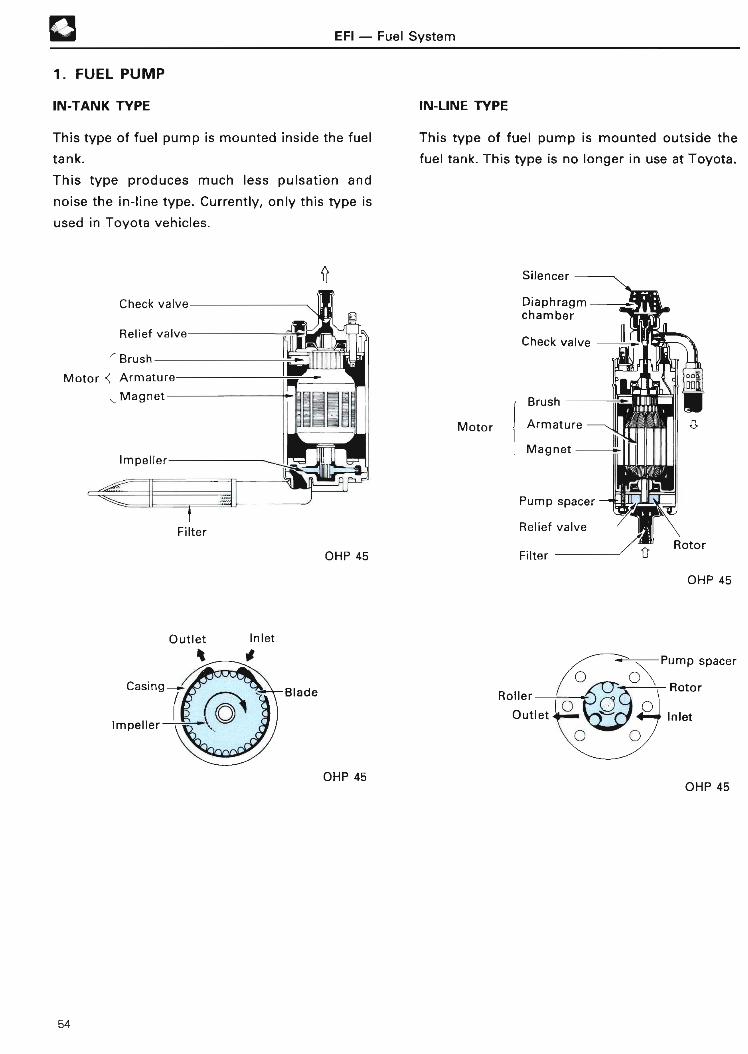
0 EFI - Fuel Syste m
1 . FUEL PUM P
IN-TANK TYPE IN-LINE TYPE
This type of fuel pump is mounted inside the fuel This type of fuel pump is mounted outside the
tank. fuel tank. This type is no longer in use at Toyota .
This type produces much less pulsation and
noise the in-line type . Currently, only this type is
used in Toyota vehicles .
OHP 45
Motor
Silencer
Diaphragm -chambe r
Check valve -
Brush
Armature
Magnet
Pump space r
Relief valv e
Filter
Mj5LX]TER--A0 0
Roto r
OHP 45
Outlet Inlet
t - it
Casing
Impeller
Blade
OHP 45OHP 4 5
54

EFI - Fuel Syste m
2 . FUEL PUMP CONTRO L
The fuel pump in a vehicle equipped with an EFI
engine operates only when the engine is
running. This is to prevent fuel from being
pumped to the engine when the ignition switch
is on but the engine is stopped .
The following types of fuel pump control are in
use at present :
On-offcontro l
Fuel pumpcontrolmethod
LI On-of fL control
withspeedcontrol
By Engine ECU
By fuelpump switch
By Engine ECU,fuel pump controlrelay and resistor
By Engine ECUand fuel pumpEC U
ON-OFF CONTROL (BY ENGINE ECU) *
1) Engine cranking
When the engine is cranking, current flows from
the IG terminal of the ignition switch to the Li
coil of the EFI main relay, turning the relay on .
At the same time, current flows from the ST
terminal of the ignition switch to the L3 coil of
the circuit-opening relay, turning it on to operate
the fuel pump.
Battery
The starter operates next and the engine begins
to crank, at which point the Engine ECU receives
an NE signal . This signal causes the transistor
inside the Engine ECU to go on, and current
therefore flows to the L2 coil of the circuit-
opening relay .
~2 Engine started
After the engine sta rts and the ignition switch is
returned from the START position ( ST terminal)
to the ON position (IG terminal), current flowing
to the L3 coil of the circuit-opening relay is cut
off . However, current continues to flow to the L :
coil, while the engine is running, due to the
transistor inside the Engine ECU being on . As a
result, the circuit-opening relay stays on,
allowing the fuel pump to continue operating .
($) Engine stopped
When the engine stops, the NE signal to the
Engine ECU stops . This turns off the transistor,
thereby cutting off the flow of current to the L2
coil of the circuit-opening relay . As a result, the
circuit-opening relay turns off, turning off the
fuel pump.
D-EFI systems and L-type EFI with optical Kar-
man vortex type air flow meter or hot-wire
type air flow meter .
55

❑~►
REFERENCE
Circuit-opening Relay
EFI - Fuel System
The resistor R and the capacitor C in the
circuit-opening relay are for the purpose of
preventing the relay contacts from opening
when current stops flowing in coil L2 due to
electrical noise (fuel pumps controlled by the
ECU) or to sudden drops in the intake ai r
ON-OFF CONTROL (BY FUEL PUMP SWITCH) *
~) Engine cranking
When the engine is cranking, current flows from
the IG terminal of the ignition switch to the Li
coil of the EFI main relay, turning the relay on .
Current also flows from the ST terminal of the
ignition switch to the La coil of the circuit-
opening relay, turning it on to operate the fuel
pump. After the engine starts, the cylinders
begin drawing in air, causing the measuring
plate inside the air flow meter to open . This
turns on the fuel pump switch, which is
connected to the measuring plate, and current
flows to the Lz coil of the circuit-opening relay .
~2 Engine sta rted
After the engine sta rts and the ignition switch is
turned from START back to ON, current flowing
volume ( fuel pumps controlled by fuel pump
switch) .They also serve to prevent sparks from being
generated at the relay contacts .
On some recent models, an L3 coil is not
provided in the circuit-opening relay.
to the La coil of the circuit-opening relay is cut
off. However, current continues to flow to the Ls
coil, while the engine is running, due to the fuel
pump switch inside the air flow meter being on .
As a result, the circuit-opening relay stays on,
allowing the fuel pump to continue operating .
~3 Engine stopped
When the engine stops, the measuring plate
completely closes and the fuel pump switch is
turned off. This cuts off the flow of current to
the Ls coil of the circuit-opening relay . As a
result, the circuit-opening relay goes off and the
fuel pump stops operating .
L-type EFI with vane type air flow meter .
Check (m pT~ Circuit-opening rela yconnector
Battery
2P fuel pump check connector (someengines only)
- IN
OHP 46
56
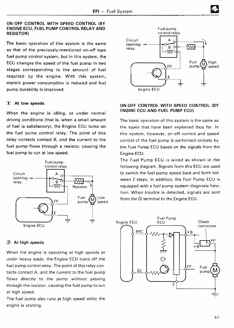
EFI - Fuel Syste m
ON-OFF CONTROL WITH SPEED CONTROL (BYENGINE ECU, FUEL PUMP CONTROL RELAY ANDRESISTOR )
The basic operation of this system is the same
as that of the previously-mentioned on-off type
fuel pump control system, but in this system, the
ECU changes the speed of the fuel pump in two
stages corresponding to the amount of fuel
required by the engine . With this system,
electric power consumption is reduced and fuel
pump durability is improved .
~ At low speeds
When the engine is idling, or under normal
driving conditions (that is, when a small amount
of fuel is satisfactory), the Engine ECU turns on
the fuel pump control relay. The point of this
relay contacts contact B, and the current to the
fuel pump flows through a resistor, causing the
fuel pump to run at low speed .
Fuel pumpcontrol relay
Engine EC U
c?i At high speed s
When the engine is operating at high speeds or
under heavy loads, the Engine ECU turns off the
fuel pump control relay . The point of this relay con-
tacts contact A, and the current to the fuel pump
flows directly to the pump without passing
through the resistor, causing the fuel pump to run
at high speed .
The fuel pump also runs at high speed while the
engine is starting .
Fuel pumpcontrol relay
Engine ECU
FuelFP pump
®
Highspeed
ON-OFF CONTROL WITH SPEED CONTROL (BYENGINE ECU AND FUEL PUMP ECU )
The basic operation of this system is the same as
the types that have been explained thus far . In
this system, however, on-off control and speed
control of the fuel pump is performed entirely by
the Fuel Pump ECU based on the signals from the
Engine ECU .
The Fuel Pump ECU is wired as shown in the
following diagram . Signals from this ECU are used
to switch the fuel pump speed back and forth bet-
ween 2 steps . In addition, the Fuel Pump ECU is
equipped with a fuel pump system diagnosis func-
tion . When trouble is detected, signals are sent
from the DI terminal to the Engine ECU .
57

3 . FUEL FILTER
EFI - Fuel Syste m
The fuel filter filters out dirt and other foreign
particles from the fuel .
Out
Q
Q
I n
4. PULSATION DAMPER
OHP 48
The pulsation damper absorbs variations in fuel
line pressure by means of a diaphragm .
Delive ry pipeOHP 48
REFERENCE
In the 4A-FE engine and some other engine
models, the pulsation damper is no longer
necessary because the fuel line has been
simplified .
5 . PRESSURE REGULATOR
The pressure regulator regulates the fuel
pressure to the injectors in accordance with the
intake manifold pressure .
4
To fuel return hos e
PRESSURE-UP CONTROL SYSTEM
OHP 48
In some engines, the fuel pressure is increased by
the Engine ECU when the temperature of the
coolant or ambient temperature of the engine is
too high during engine cranking . The Engine ECU
causes more air to be drawn into the chamber of
the pressure regulator to increase the fuel
pressure . This prevents vapor lock at high engine
temperatures in order to help the engine start
when it is warm .
Fromdelive ry~>pipe
Some models only OHP 48
58

EFI - Fuel System
If the engine is cranked when the coolant
temperature is 100°C (212°F) or higher, the
Engine ECU turns on the VSV (the exact
temperature depends on the engine model) .
When the VSV goes on, atmospheric air is
introduced into the diaphragm chamber of the
pressure regulator, causing the fuel pressure to
become higher than that under normal engine
operating conditions . After the engine is started,
the VSV remains on for about two minutes .
There are some engine models in which a water
temperature sensor (THW) is used instead of a
water temperature switch (TSW) .
There are also engines in which other signals
besides the coolant temperature are used in
pressure-up control . These signals include the
intake air temperature (THA) signal, the intake
air volume (VS or PIM) signal, and the engine
speed (NE) signal .
101 .3
(1 kgf/cmz )
0
NOTE
1 . On some recent models, intake manifold
pressure is not connected to the pressure
regulator .
Fuel pressure is always maintained at a con-
stant pressure higher than the atmospheric
pressure . As a result, changes in injection
volume caused by intake manifold pressure
are corrected by the Engine ECU .
VSV: on
OHP 48
2 . In addition to the models described in 1
above, there are also models in which the
pressure regulator is provided in the fuel
tank . Since there is no fuel return pipe, it
becomes difficult for air bleed once it has
entered the fuel pipe . It is for this reason
that more time is required to start the
engine after the fuel fiiter or similar compo-
nent has been replaced .
6. INJECTORS
The injector is an electromagnetically-operated
nozzle which injects fuel in accordance with
signals from the ECU .
Inlet
4
SIDE-FEED TYPE TOP-FEED TYPE
OHP 49
,,-- wv IInternal Resistance of Injector
There are two types of injector, which differ in
their internal resistance level :
• High-resistance type: approx . 13 .8 Q
• Low-resistance type : approx. 1 .5 ^- 3 Sd
59

EFI - Fuel System
7 . INJECTOR DRIVE METHOD S
There are two injector drive methods . One is the
voltage control method, and the other is the
current control method .
High-resistanceinjectors(Most engines )
Voltagecontro l
Injectordrivemethod
Low-resistanceinjectors(Some engines)
VOLTAGE CONTROL METHOD FOR LOW-RESISTANCE INJECTORS
The electrical circuitry for this type of injector,
as well as its operation, are basically the same
as for the high-resistance injector, but since a
low-resistance injector is used, a solenoid
resistor is connected between the ignition
switch and the injectors .
The electrical circuitry for simultaneous injection
(See page 66) is shown below .
Ignition switch
Currentcontrol
Low-resistance injectors(No longer in use )
VOLTAGE CONTROL METHOD FOR HIGH-RESISTANCE INJECTOR S
Battery voltage is applied to the injectors
directly via the ignition switch .
When the transistor (Tr) in the Engine ECU goes
on, current flows from terminals No . 10 and No.
20 to E01 and E02. While the Tr is on, current
flows through the injectors and fuel is injected .
The electrical circuitry for simultaneous injection
(See page 66) is shown below.
Ignition switch
OHP 49
OHP 49
60
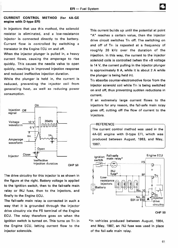
EFI - Fuel Syste m
CURRENT CONTROL METHOD (for 4A-GEengine with D-type EFI)
In injectors that use this method, the solenoid
resistor is eliminated, and a low-resistance
injector is connected directly to the battery.
Current flow is controlled by switching a
transistor in the Engine ECU on and off .
When the injector plunger is pulled in, a heavy
current flows, causing the amperage to rise
quickly . This causes the needle valve to open
quickly, resulting in improved injection response
and reduced ineffective injection duration.
While the plunger is held in, the current is
reduced, preventing the injector coil from
generating heat, as well as reducing power
consumption .
On
Injection Offsignal ~
Voltage 12 V, 20kHzwaveform
0V i
~CT
B AAmperagewaveform
®
This current builds up until the potential at point
"A" reaches a certain value, then the injector
drive circuit switches Tri off . The switching on
and off of Tr, is repeated at a frequency of
roughly 20 kHz over the duration of the
injection . In this way, the current to the injector
solenoid coils is controlled (when the +B voltage
is 14 V, the current pulling in the injector plunger
is approximately 8 A, while it is about 2 A while
the plunger is being held in) .
Tr2 absorbs counter-electromotive force from the
injector solenoid coil while Tri is being switched
on and off, thus preventing sudden reductions in
current .
If an extremely large current flows to the
injectors for any reason, the fail-safe main relay
goes off, cutting off the flow of current to the
injectors .
REFERENCE
The current control method was used in the
4A-GE engine with D-type EFI, which was
produced between August, 1983, and May,
1987 .
Ineffectiveinjection duration
OHP 50
The drive circuitry for this injector is as shown in
the figure at the right . Battery voltage is applied
to the ignition switch, then to the fail-safe main
relay or INJ fuse, then to the injectors, and
finally to the Engine ECU .
The fail-safe main relay is connected in such a
way that it is grounded through the injector
drive circuitry via the FS terminal of the Engine
ECU . The relay therefore goes on when the
ignition switch is turned on . This turns on Tr, in
the Engine ECU, letting current flow to the
injector solenoids .
IgnitionFail-safe
switch main relay* Engine EC U
OHP 50
*In vehicles produced between August, 1984,
and May, 1987, an INJ fuse was used in place
of the fail-safe main relay .
61
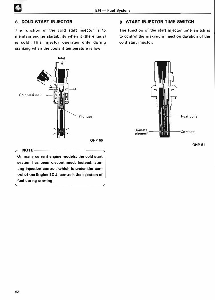
EFI - Fuel Syste m
8. COLD START INJECTOR 9 . START INJECTOR TIME SWITC H
The function of the cold start injector is to The function of the start injector time switch is
maintain engine startability when it (the engine) to control the maximum injection duration of the
is cold . This injector operates only during cold start injector .
cranking when the coolant temperature is low .
Inlet
Plunger
Bi-metalelement
OHP 50
NOTE
On many current engine models, the cold start
system has been discontinued . Instead, star-
ting injection control, which is under the con-
trol of the Engine ECU, controls the injection of
fuel during starting .
Heat coils
Contact s
OHP 5 1
62

EFI - Fuel Syste m
10. COLD START INJECTOR ELECTRICALCIRCUITRY
CONTROLLED BY START INJECTOR TIMESWITCH
When the engine is cranked while the engine
coolant temperature is low, the duration of cold
start injector operation is controlled by the start
injector time switch .
ST terminal
CONTROLLED BY ECU (STJ CONTROL )
In order to improve startability when the engine
is cold, the injection duration of the cold start
injector is controlled not only by the start
injector time switch but also by the Engine ECU
in accordance with the coolant temperature .
Control of the injection duration of the cold start
injector continues to be carried out by the start
injector time switch, as shown by shaded area A
in the figure below, but control is also exercised
by the Engine ECU, as shown by shaded area B
in the figure .
Engine ECU
STA STA
OHP 5 1
I
-20 0 20 40 60(-4) (32) (68) (104) (140 )
Coolant temperature °C (°F )
On or off depending on engine model
OHP 51
UNN
C 6-0co
4-C0
a0
i 2--S
0
STJ I I STA
A, B
-20 0 20 40 6 0(-4) (32) (68) (104) (140)
Coolant temperature °C (°F )
A: Controlled by start injector time switch
B: Controlled by EC U
A, B: Controlled by sta rt injector time switch andECU
OHP 5 1
63

aAIR INDUCTION SYSTEM
EFI - Air Induction Syste m
This system supplies the air necessary for
combustion to the cylinders . Air passes through
the air cleaner, then through the air flow meter
(in L-type EFI only), the throttle body, the air
intake chamber, and the intake manifold, then is
fed into each cylinder. In an EFI engine,
releasing the accelerator pedal closes the
throttle valve fully, so during idling or fast
idling, air bypasses the throttle valve and is
taken directly into the cylinders via the bypass
passage in the throttle body or ISC valve .
AIRCLEANER
AIR FLOWMETER(L-type EFI)
THROTTLEBODY
AIR VALVEand/o r
ISC VALVE
Air cleane r
N
When the coolant temperature is low, the air
valve opens and air passes through it (in
addition to passing through the throttle body as
usual) and enters the air intake chamber. This
extra air raises the idle speed to aid in engine
warm-up .
In engines equipped with some types of ISC
valves, the above is performed not by an air
valve, but by the ISC valve . Please refer to the
section on the ISC system (see page 99) .
AIR INTAKECHAMBER
INTAKEMANIFOLD
Thrott le bodyBypass passage Idle speed adjusting screw
Air valve
D - TYPE EFI (engine without ISC valve )
Air flow meter
N
Airintakechambe r
4 r OHP 52
CYLINDER S
Idle speed adjusting screw(Some models only )
L -TYPE EFI (engine with ISC valve)
OHP 52
64

EFI - Air Induction Syste m
1 . THROTTLE BODY
The throttle body consists of the throttle valve,
which controls the intake air volume during
normal engine operation, a bypass passage
through which a small volume of air passes
during idling, and a throttle position sensor
which detects the opening angle of the throttle
valve . Some throttle bodies are also equipped
with a dashpot which causes the throttle valve
to return gradually when it is closed or with a
wax type air valve .
During idling, the throttle valve is fully closed .
As a result, intake air flows through the bypass
passage into the air intake chamber .
The engine speed during idling can be adjusted
by the idle speed adjusting screw, which
increases or decreases the volume of air passing
through the bypass passage. (See the illustration
of the wax type air valve at right . )
NOTE
The idle speed adjusting screw adjusts the
idle speed, just as the throttle adjusting
screw does on a carburetor .
In engines equipped with a stepper motor
type or rotary solenoid type ISC valve, the
volume of air flowing through the bypass
passage is controlled by the ISC valve .
Therefore, in some engines, the idle speed
adjusting screw is set to the fully-closed
position at the factory, while in others, an
idle adjusting screw is not provided .
2 . AIR VALVE
The air valve controls the engine idling speed
when the engine is cold .
Some engines equipped with an ISC valve do
not use this air valve . (For further details on the
ISC valve, see page 99 . )
WAX TYPE
The wax type air valve consists of a thermo
valve and a gate valve .
The thermo valve is filled with thermo wax . The
volume of this wax changes according to the
coolant temperature . The wax type air valve
utilizes these characteristics of the thermo wax
to open and close the gate valve in order to
control the engine idling speed .
Idle speed adjusting scre w
Bypass passag e
Coolant
Thrott levalve
BI-METAL TYPE
OHP 53
The bi-metal type air valve consists of a bi-
metal element, a heat coil, and a gate valve .
Current flows simultaneously to the heat coil
and the fuel pump. This heats the element,
causing it to change shape . This in turn causes
the gate to close gradually .
Heat coil (ja To air intakeBi-metal \ IP~ chamberelement
Gate valve
From air cleaner OHP 53
65
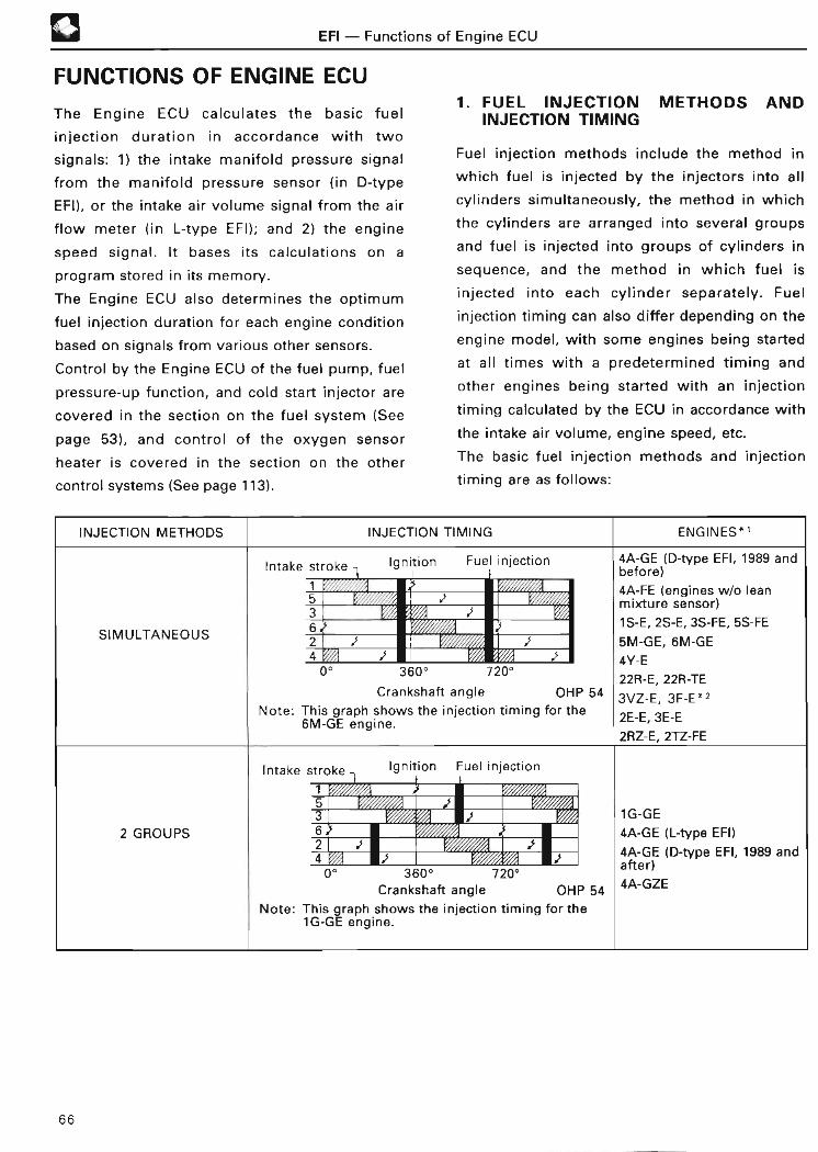
EFI - Functions of Engine EC U
FUNCTIONS OF ENGINE EC U
The Engine ECU calculates the basic fuel
injection duration in accordance with two
signals : 1) the intake manifold pressure signal
from the manifold pressure sensor (in D-type
EFI), or the intake air volume signal from the air
flow meter (in L-type EFI) ; and 2) the engine
speed signal . It bases its calculations on a
program stored in its memory .
The Engine ECU also determines the optimum
fuel injection duration for each engine condition
based on signals from various other sensors .
Control by the Engine ECU of the fuel pump, fuel
pressure-up function, and cold start injector are
covered in the section on the fuel system (See
page 53), and control of the oxygen sensor
heater is covered in the section on the other
control systems (See page 113) .
1 . FUEL INJECTION METHODS ANDINJECTION TIMING
Fuel injection methods include the method in
which fuel is injected by the injectors into all
cylinders simultaneously, the method in which
the cylinders are arranged into several groups
and fuel is injected into groups of cylinders in
sequence, and the method in which fuel is
injected into each cylinder separately . Fuel
injection timing can also differ depending on the
engine model, with some engines being started
at all times with a predetermined timing and
other engines being started with an injection
timing calculated by the ECU in accordance with
the intake air volume, engine speed, etc .
The basic fuel injection methods and injection
timing are as follows :
INJECTION METHODS INJECTION TIMING ENGINES* '
Intake stroke Ignition Fuel injection 4A-GE (D-type EFI, 1989 an dbefore )
4A-FE ( en ines w/o lea ng5 ' mixture sensor )3 3
S 63 1S-E, 2S-E, 3S-FE, 5S-F ESIMULTANEOU
2 t t 5M-GE, 6M-GE4 4Y- E0° 360° 720` 22R-E, 22R-TE
Crankshaft angle OHP 54 3VZ-E, 3F-E* 2Note : This graph shows the injection timing for the 3E-E2E- E6M-GE engine . ,
2RZ-E, 2TZ-FE
Intake stroke - Ignition Fuel injectio n
~T.
5 t3 1G-GE
2 GROUPS 6 4A-GE ( L-type EFI )2 3 3 d4 ' 4A GE (D type EFI, 1989 a n. )ft0° 360° 720°
e ra
Crankshaft angle OHP 54 4A-GZE
Note: This graph shows the injection timing for th e1G-GE engine .
66

EFI - Functions of Engine ECU 13INJECTION METHODS INJECTION TIMING ENGINES* '
Intake stroke Ignition Fuel injectio n
153 7M-GE
3 GROUPS 6 7M-GTE
4 i s 2VZ-FE
0° 3600 7200Crankshaft angle OHP 54
Note : This graph shows the injection timing for th e7M-GE engine.
Intake stroke Ignition Fuel injectio n
1 f8 i i 1_ 01 14 i i
4 GROUPS 3 j 1UZ-FE6 i f
5 S f72 i
0° 360° 720° 1080°Crankshaft angle OHP 54
Intake stroke Ignition Fuel injectio n
INDEPENDENT3S-G E
SEQUENTIAL)3S-GTE
( 2 4A-FE (engines w/lea n
0° 360° 720° 1080°
Crankshaft angle
OHP 54
mixture sensor )
FOR 1S-i
Intake stroke i Ignition Fuel injectio n
1 t
34
2 t
S- i
0` 360° 720° 1080°
Crankshaft angle OHP 54
1 Applicable engines were manufactured in September 1991 .
Refer to the respective engine Repair Manuals or Electrical Wiring Diagrams for later changes and addi-
tions .
2 The fuel injection volume in the 3F-E engine is controlled separately for the front three cylinders and the
rear three cylinders . However, since fuel is injected into the front and rear cylinders once each time the
crankshaft turns, injection is simultaneous .
,-- NOTE
There are some engines in which basic fuel injection methods and the injection method employed during
starting are different .
67

® EFI - Functions of Engine EC U
2 . FUEL INJECTION DURATION CONTRO L
The actual fuel injection duration is determined
by two things: 1) the basic injection duration,
which is, in turn, determined by the intake air
volume and the engine speed ; and 2) various
corrections based on signals from the various
sensors. (During engine starting [cranking],
however, fuel injection duration is determined
differently, because the amount of intake air i s
r- Sta rt ing injection contro l
Fuel injection
duration control
' After-sta rt injection control
not stable during cranking . See page 70 for more
details .) Corrections differ depending on the
engine model, because each respective engine
has its own characteristics to take into
consideration.
The following table shows the main controls that
make up fuel injection control :
Basic injection duration control
Intake air temp . correction
Voltage correctio n
Basic injection duration contro l
Injectioncorrections
Voltage correctio n
,,-- REFERENC E
Fuel injection duration control consists of syn-
chronous injection, in which injection is per-
formed at a predetermined crankshaft angle as
described above as well as asynchronous injec-
tion in which injection is performed irrespective
of the crankshaft angle .
Asynchronous injection consists of starting in-
jection control in which injection is performed
only once during cranking and acceleration in-
jection in which injection is performed only
once during acceleration .
Synchronous
F injectio n
Fuelinjectiondurationcontrol
Asynchronous
injection
Intake air temp . correction
After-start enrichment
Warm-up enrichment
Air-fuel ratio correction during
transition
Power enrichment
Air-fuel ratio feedbackcorrectio n
CO emission control correction
Idling stability correction
High-altitude compensation
correction
Fuel cut-off
Starting injection~ contro l
_After-start injectioncontrol
rStarting injection contro l
L Acceleration injectioncontro l
68

EFI - Functions of Engine EC U
The relationship between fuel injection duration
control and the major signals from each sensor is
shown in the following table :
®
REFERENCE
The signals used for each type of control may
differ depending on the engine model .
N
SIGNALS w w
0 _J a. P: z W a- CC U) 7h
HL LU_J (LM V) x v) cc~
w DxN
w wxa d=
¢~ H C7 p
za ?d x u
FUEL INJECTION DURATION CONTROL m Neu 0 0 U_ ( L;oZ 0 w M N
j= N
a s
Starting injection control 0 0 0 0 0
Basic injection For D-type EFI 0 0duration control For L-type EFI 0 11 0
Intake air temp . correction 0
After-sta rt enrichment 0 0
Warm-up enrichment 0
Power enrichment 0 0 0 0
Acceleratio nAir-fuel ratio enrichment 0 0 0 0 0 0correction correctio n
during Deceleratio ntransition lean 0 0 0 0 0 0
After-sta rt correctio n
injection control Air-fuel Oxygen 042 ratio senso r
feedback Lean mixture 0correction senso r
CO emission contro lcorrection * O O
Idling stability correction 0 0
High-altitude compensation 0correctionDuringdeceleration O 0 O 0
Fuel cut-off At highengine 0speeds
At highvehicle 0speed s
Voltage correction -To-* Only engines without oxygen sensor or lean mixture sensor .
69

START INJECTION CONTROL
EFI - Functions of Engine EC U
During engine starting, it is difficult for the
manifold pressure sensor (for D-type EFI) or the
air flow meter (for L-type EFI) to accurately
sense the manifold pressure or the amount of air
being taken in, due to large fluctuations in
engine speed . For this reason, the Engine ECU
selects from its memory a basic injection
duration that is suitable for the coolant
temperature and engine speed, regardless of in-
take manifold pressure or intake air volume . It
then adds to this an intake air temperature correc-
tion (See page 72) and a voltage correction (See
page 79) to obtain the actual injection duration .
When the weather is cold, the cold start
injection system operates in order to improve
startability (See page 63) .
Basic injection durationduring sta rt in g
• THW
OHP 55Injection signal during start ing
Low
---- On some models, injectionduration increases a s
•N E
Intake air temperaturecorrection
•THA
Voltage correction
• +B
20(68)
Coolant temperature °C (°F)
High
OHP 55
-RELEVANT SIGNALS
• Crankshaft angle (G)
• Engine speed (NE )
• Coolant temperature (THW)
• Intake air temperature (THA)
• Battery voltage (+B )
REFERENCE
In some engine models, the starter (STA)
signal is also used to inform the Engine ECU
that the engine is being cranked .
70

EFI - Functions of Engine ECU
AFTER-START INJECTION CONTRO L
When the engine is running at a more-or-less
steady speed above a predetermined rpm, the
Engine ECU determines the injection signal
duration as explained below :
Injection signal duration = basic injection
duration x injection correction* + voltage
correction
*Injection correction is the sum and product of
various correction coefficients .
Basic injection duration
• VS, KS, VG or PI M
• N E
Injection corrections
• TH W
• THA
• PSW or VTA
• Other s
Voltage correction
• +B
Actual injection duratio n
Injection signal
OHP 55
1 Basic injection duration
FOR D-TYPE EF I
This is the most basic injection duration, and is
determined by the manifold pressure (PIM
signal) and the engine speed (NE signal) . The
internal memory of the Engine ECU contains
data on various basic injection durations for
various manifold pressures and engine speeds .
-RELEVANT SIGNALS
• Intake manifold pressure (PIM)
• Engine speed (NE )
REFERENCE
Since the intake efficiency varies depending on
the valve clearance, the intake air volume may
vary even if the intake manifold pressure stays
the same .
Therefore, in D-type EFI, when the valve
clearance varies, the air-fuel ratio of the air-fuel
mixture will change slightly .
• Since engines equipped with an oxygen sen-
sor correct injection duration according to
the air-fuel ratio feedback correction, the
air-fuel ratio is always maintained at the op-
timal level .
• In engines which are not equipped with an
oxygen sensor, the air-fuel ratio is adjusted
by a variable resistor (See page 41) .
71

0FOR L-TYPE EFI
EFI - Functions of Engine EC U
This is the most basic injection duration, and is
determined by the volume of air being taken in
(VS, KS or VG signal) and the engine speed (NE
signal) . The basic injection duration can be ex-
pressed as follows :
Basic injection Intake air volumeduration =K x Engine speed
where K : correction coefficient
-RELEVANT SIGNAL S
• Intake air volume (VS, KS or VG)
• Engine speed (NE)
2 Injection corrections
The Engine ECU is kept informed of engine
running conditions at each moment by means of
signals from various sensors. It then makes
various corrections in the basic injection
duration based on these signals .
INTAKE AIR TEMPERATURE CORRECTIO N
The density of the intake air will change
depending on its temperature. For this reason,
the Engine ECU must be kept accurately
informed of the intake air temperature (by
means of the intake air temperature sensor) so
that it can adjust the injection duration to
maintain the air-fuel ratio that is currently
required by the engine. For this purpose, the
ECU considers 20°C (68°F) to be the "standard
temperature" and increases or decreases the
amount of fuel injected depending upon whether
the intake air temperature falls below or rises
above this temperature .
This correction results in an increase or decrease
in the injection volume by a maximum of about
10% (for the Karman vortex type air flow meter,
this is about 20%) .
In case of hot-wire type air flow meters, since
the air flow meter itself outputs a signal that is
corrected by the intake air temperature, the in-
take air temperature correction is not
necessary .
,,- ivv I r-
Low 20 High(68 )
Intake air temperature °C (°F )
-RELEVANT SIGNAL
• Intake air temperature (THA)
OHP 55
72

EFI - Functions of Engine EC U
AFTER-START ENRICHMENT
Immediately after starting (engine speed above
a predetermined rpm), the Engine ECU causes an
extra amount of fuel to be supplied for a
predetermined period to aid in stabilizing engine
operation . The initial after-start enrichment
correction is determined by the coolant
temperature, and the amount gradually falls
thereafter at a certain constant rate .
When the temperature is extremely low, this
enrichment roughly doubles the injection
volume.
1 .0 r -------------------------------
0 *Low ~ (6 OA- High
Coolant temperature °C (°F)
Depending on the engine models .
-RELEVANT SIGNALS
• Engine speed (NE )
• Coolant temperature (THW)
OHP 56
REFERENCE
In some engine models, the starter (STA)
signal is used as a condition for beginning this
correction .
WARM-UP ENRICHMENT
❑
Since fuel vaporization is poor when the engine
is cold, the engine will run poorly if a richer fuel
mixture is not supplied .
For this reason, when the coolant temperature is
low, the water temperature sensor so informs
the Engine ECU, which increases the amount of
fuel injected to compensate until the coolant
temperature reaches the predetermined
temperature .
When the temperature is extremely low, this
enrichment roughly doubles the injection
volume.
Low- 60" ~High(140 )
Coolant temperature °C (°F )
Depending on the engine models .
-RELEVANT SIGNA L• Coolant temperature (THW)
OHP 56
REFERENCE
In some engine models, the amount of this
enrichment changes slightly when the IDL
signal goes on or off, and it also changes in
accordance with the engine speed .
73

®
POWER ENRICHMENT
EFI - Functions of Engine EC U
When the engine is operating under a heavy
load, the injection volume is increased in
accordance with the load in order to ensure
proper engine operation .
Methods for sensing whether the engine is
operating under a heavy load differ depending
on the engine model . In some engines, it is
determined by the throttle valve opening angle,
while in other engines, it is determined by the
intake air volume . This enrichment increases the
injection volume by 10 to 30% .
-RELEVANT SIGNAL S
• Throttle position (PSW or VTA )
• Intake manifold pressure ( PIM) or intake air
volume (VS, KS or VG)
• Engine speed (NE )
(_REFERENCE1 . In some engine models, the amount of
increase also differs in accordance with
the coolant temperature .
2 . In some engine models, when the coolant
temperature is high, the fuel injection
amount is increased to lower the exhaust
gas temperature and to prevent the
engine from overheating .
3 . In some engine models, the kick-down
switch (KD) signal is used as a condition
for begining this correction .
AIR-FUEL RATIO CORRECTION DURINGTRANSITION S
A "transition" is the moment when the engine
rpm changes, either during acceleration or
deceleration . During a transition, the injection
volume must be increased or decreased to
assure proper engine pe rformance .
a . Acceleration Enrichment Correctio n
When the Engine ECU detects engine
acceleration based on signals from the
various sensors, it increases the injection
volume to improve acceleration
performance .
The initial correction value is determined by
the coolant temperature and the rate of
acceleration . The amount gradually
decreases from that point .
b. Deceleration Lean Correctio n
When the ECU detects engine deceleration,
it decreases the injection volume as
necessary to prevent over-rich injection
during deceleration .
-RELEVANT SIGNAL S
• Intake manifold pressure ( PIM) or intake air
volume (VS, KS or VG )
• Engine speed (NE )
• Vehicle speed (SPD )
• Throttle position (IDL, PSW or VTA)
• Coolant temperature (THW )
74

EFI - Functions of Engine ECU
AIR-FUEL RATIO FEEDBACK CORRECTIO N
a . Oxygen Senso r
The Engine ECU corrects the injection duration
based on the signals from the oxygen sensor to
keep the air-fuel ratio within a narrow range
near the theoretical air-fuel ratio . (This is called
a "closed-loop" operation . )
In order to prevent overheating of the catalyst
and assure good engine operation, air-fuel ratio
feedback does not occur under the following
conditions (open-loop operation) :
• During engine sta rt in g
• During after-start enrichment
• During power enrichmen t
• When the coolant temperature is below a
predetermined leve l
• When fuel cut-off occurs
• When the lean signal continues longer than a
predetermined tim e
The ECU compares the voltage of the signals
sent from the oxygen sensor with a
predetermined voltage . If the voltage of a signal
is higher than that voltage, it judges the air-fuel
ratio to be richer than the theoretical air-fuel
ratio and reduces, at a constant rate, the amount
of fuel injected . If the voltage of a signal is
lower, it judges that the air-fuel ratio is leaner
than the theoretical air-fuel ratio, and increases
the amount of fuel injected .
The correction coefficient used by the ECU
varies over a range of 0 .8 to 1 .2, and is 1 .0
during an open loop operation .
High
(rich)
RELEVANT SIGNAL
~Oxygen sensor (OX)
OHP 56
Two oxygen sensors are used on some models .
Even if the signal of the main oxygen sensor
changes over time, the air-fuel ratio can be main-
tained within a narrow range near the theoretical
air-fuel ratio by using a sub oxygen sensor . In addi-
tion, catalyst deterioration can be also detected
by comparing the signals of the two oxygen sen-
sors .
Catalytic converte r
Decreased Increased
OHP 56
Engine ECU
75

NOTE
Air-fuel ratio learned control ;
EFI - Functions of Engine EC U
When engine condition changes over time, the
air-fuel ratio that is created from basic injection
duration calculated by the Engine ECU deviates
from the theoretical air-fuel ratio . When this
happens, time is required for the air-fuel ratio to
return to the theoretical air-fuel ratio by air-fuel
ratio feedback correction . The deviation may
also exceeds the correction range of air-fuel
ratio feedback correction .
Consequently, the Engine ECU remembers the
central value of the correction ratio and cor-
rects the amount of deviation from the central
value (a) for basic injection duration . This func-
Correctionratio
1 . 2
1 . 0
0.8Lean mixture
Normalcondition
b. Lean Mixture Senso r
The ECU corrects the injection duration based on
signals from the lean mixture sensor to keep the
air-fuel ratio within the "lean" range . (This is
called a "closed-loop" operation . )
In order to prevent overheating of the catalyst
and assure good engine operation, air-fuel ratio
feedback does not occur under the following
conditions (open-loop operation) :
• During engine startin g
• During after-start enrichment
• During power enrichmen t
• When the coolant temperature is below a
predetermined leve l
• When fuel cut-off occurs
tion is referred to as air-fuel ratio learned con-
trol, and the value remembered by the Engine
ECU is referred to as the learned value .
As a result of this learned control, air-fuel feed-
back correction is constantly able to correct
the central value of the correction ratio with a
value of 1 .0 .
This enables the air-fuel ratio to return rapidly
within a narrow range near the theoretical air-
fuel ratio . Furthermore, learned control is per-
formed when feedback correction is being per-
formed .
Central feedback valu e
Over lifetime
The ECU determines the target air-fuel ratio
based on signals from the sensors . It then
converts this ratio to an electric current and
compares this current with the current from the
lean mixture sensor . If the current from the lean
mixture sensor is larger than the target current,
it judges the air-fuel ratio to be leaner than the
target air-fuel ratio and increases the amount of
fuel injected . If the current from the lean
mixture sensor is smaller, it judges that the air-
fuel ratio is richer than the target air-fuel ratio,
and reduces the amount of fuel injected .
The correction coefficient used by the ECU
varies over a range of 0 .8 to 1 .2, and is 1 .0
during an open-loop operation .76

EFI - Functions of Engine EC U
LSsigna l
Correctionratio
Decreased Increased
Engine ECU
Large
Targetcurrent
Smal l
OHP 57
❑
Idlemixtureadjustincscrew
OHP 5 7
D-type EFI without oxygen senso rL-type EFI without oxygen sensor but with op-tical Karman vortex type air flow meter orhot-wire type air flow mete r
The ECU also reduces CO emissions bycontrolling the injection volume in accordancewith the engine speed .
RELEVANT SIGNA L
• Lean mixture sensor (LS)
OHP 57
CO EMISSION CONTROL CORRECTION
(D-type EFI'' and L-type EFI'z )
The injection volume can be adjusted by
manually adjusting the variable resistor (See
page 41) . This can be used to adjust the volume
of CO emissions .
RELEVANT SIGNALS• Variable resistor (VAF)• Engine speed (NE )
NOTICEIt is usually not necessary to adjust the idlemixture in most models, provided that thevehicle is in good condition . However, if itdoes become necessa ry to do so, always usea CO meter . If a CO meter is not available, itis best not to attempt to adjust the idlemixture if at all possible .
REFERENCE
When the voltage of the terminal VAF is 0.1 V
or less or 4 .9 V or more, the Engine ECU discon-
tinues CO emission control correction .
Variable resistor
77
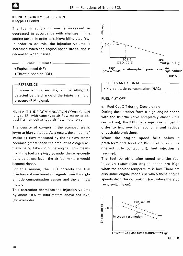
IDLING STABILITY CORRECTION(D-type EFI only)
EFI - Functions of Engine ECU
The fuel injection volume is increased or
decreased in accordance with changes in the
engine speed in order to achieve idling stability .
In order to do this, the injection volume is
increased when the engine speed drops, and is
decreased when it rises .
RELEVANT SIGNALS
• Engine speed (NE )
• Thrott le position (IDL)
REFERENCE
In some engine models, engine idling is
detected by the change of the intake manifold
pressure (PIM) signal .
HIGH-ALTITUDE COMPENSATION CORRECTION(L-type EFI with vane type air flow meter or op-tical Karman voltex type air flow meter only )
The density of oxygen in the atomosphere is
lower at high altitudes . As a result, the amount of
intake air flow measured by the air flow meter
becomes greater than the amount of oxygen ac-
tually being taken into the engine . This means
that if the fuel were injected under the same condi-
tions as at sea level, the air-fuel mixture would
become richer .
For this reason, the ECU corrects the fuel
injection volume based on signals from the high-
altitude compensation sensor and the air flow
m ete r .
This correction decreases the injection volume
by about 10% at 1000 meters above sea level
(for example) .
101 .3 kPa( 760, 29.9) (mmHg, in . Hg)
(low altitude) -Atmospheric pressure , Lowaltitude )
OHP 58
-RELEVANT SIGNA L
• High-altitude compensation (HAC )
FUEL CUT-OF F
a . Fuel Cut-Off during Deceleration
During deceleration from a high engine speed
with the throttle valve completely closed (idle
contact on), the ECU halts injection of fuel in
order to improve fuel economy and reduce
undesirable emissions.
When the engine speed falls below a
predetermined level or the throttle valve is
opened (idle contact off), fuel injection is
resumed .
The fuel cut-off engine speed and the fuel
injection resumption engine speed are high
when the coolant temperature is low . There are
also some engine models in which these engine
speeds drop during braking (i .e ., when the stop
lamp switch is on) .
2,000
Low-Coolant temperature - High
OHP 58
78

EFI - Functions of Engine EC U
-RELEVANT SIGNALS
• Throttle position (IDL)
• Engine speed (NE )
• Coolant temperature (THW)
• Stop lamp switch (STP )
- REFERENC E
1 . In some manual transmission models, the
clutch switch (N/C) signal is also used as a
condition for fuel cut-off .
2 . There are some models in which the fuel
will be cut off when the injection volume
during deceleration falls below the predeter-
mined level even if the throttle valve is not
completely closed (idle contact off) .i
b . Fuel Cut-Off at High Engine Speed s
To prevent engine over-run, fuel injection is
halted if the engine speed rises above a
predetermined level . Fuel injection is resumed
when the engine speed falls below this level .
RELEVANT SIGNA L
• Engine speed (NE )
c. Fuel Cut-Off at High Vehicle Speed s
In some vehicles, fuel injection is halted if the
vehicle's speed exceeds a predetermined level .
Fuel injection resumes after the speed drops
below a predetermined level .
- RELEVANT SIGNAL
• Vehicle speed (SPD )
IYV I C
The Engine ECU also performs various other
corrections in addition to these (page 72 to
79) .
3 Voltage correction
There is a slight delay between the time that the
Engine ECU sends an injection signal to the
injectors and the time that the injectors actually
open. This delay becomes longer the more the
voltage of the battery drops . This means that
the length of time that the injector valves
remain open would become shorter than that
calculated by the ECU, causing the actual air-
fuel ratio to become higher (i .e ., leaner) than
that required by the engine, if this were not
prevented by voltage correction .
In voltage correction, the ECU compensates for
this delay by lengthening the duration of the
injection signal by a period corresponding to the
length of the delay . This corrects the actual
injection period so that it corresponds with that
calculated by the ECU . (The amount of this
correction value depends on the engine model . )
Voltage correctio n
Off
Open
ClosedInjectoractually open
OHP 6 8
0I
----------------------------
Standard operatingdelay time
Low- 14-High
Batte ry voltage (V)
OHP 58
RELEVANT SIGNA L
• Battery voltage (+B)
Injectionsigna l
~
79

l-6L
OW3W

ESA - Genera l
ESA (ELECTRONIC SPARK ADVANCE )
GENERAL
®
The ESA (electronic spark advance) system is a mechanical advancer) controls the ignition
system in which an ECU (rather than a timing of the ignition system .
Igniter
Ignition coi l
OHP 59
BASIC CONSTRUCTION OF ES A
1 . IGNITION TIMING AND ENGINE RUNNING CONDITION S
In order to maximize engine output efficiency,
the air-fuel mixture must be ignited when the
maximum combustion pressure occurs ; that is, at
about 10° after TDC (top dead center) .
However, the time from ignition of the air-fuel
mixture to the development of maximum
combustion pressure varies depending on the
engine speed and the manifold pressure ; ignition
must occur earlier when the engine speed is
higher and later when it is lower. In con-
ventional EFI, the timing is advanced
retarded by a governor advancer in
distributor .
Furthermore, ignition must also be advanced
when the manifold pressure is low (i .e ., when
there is a strong vacuum) . In conventional EFI,
this is achieved by the vacuum advancer in the
distributor .
However, optimal ignition timing is also affected
by a number of other factors besides engine
speed and intake air volume, such as the shape
of the combustion chamber, the temperature
inside the combustion chamber, etc . For this
reason, governor and vacuum advancers cannot
provide ideal ignition timing for the engine . In
the ESA system, the engine is provided with
nearly ideal ignition timing characteristics .
The ESA works as follows: the ECU determines
ignition timing from its internal memory, which
contains the optimal ignition timing data for
each engine running condition, then sends the
appropriate ignition timing signal to the igniter .
Since the ESA always ensures optimal ignition
timing, both fuel efficiency and engine power
output are maintained at optimal levels .
and
the
80

® ESA - Genera l
2 . IGNITION TIMING AND GASOLINEQUALITY
ESA
Governor advance r
Engine speed - High
ADVANCING BY ENGINE SPEE D
Ideal ignitio n
Manifold vacuum - Hig h
VACUUM ADVANCIN G
timing
I
ESA
OHP 59
Vacuum advance r
OHP 59
In some engine models, two ignition timing
advance patterns, according to the fuel octane
rating ( premium or regular), are stored in the
ECU . The ignition timing can be changed to match
the gasoline being used (premium or regular) by
operating the fuel control switch or connector
(See page 40) .
In some engine models, this is done automatically
by the Engine ECU's fuel octane judgement fun-
ction (See page 116) .
81

ESA - Genera l
The following table shows the specifications for
the 4A-FE engine. Items marked with circles in
the "APPENDIX" column are included in the
specifications for each engine in the APPENDIX
section (page 188) in the back of this manual .
In addition, for those items with circle in the
"STEP 2 (IGNITION)" column in the following
table, refer to the Step 2, vol . 3 (IgnitionSystem) manual for a detailed explanation of
the relevant items .
ESA (ELECTRONIC SPARK ADVANCE)PAG E(THIS ITEM REMARK APPENDIX STEP 2MANUAL) (IGNITION )
Crankshaft angle ( initial ignition timing83 ~ )angle) judgement `
IGT (ignition timing) signal 83 0IGF (ignition confirmationl signal 84 0
Conventional ignition circuitry85 0for TCC S
Ignitioni i
DLI (distributorless ignition) 86rcu tryc system
DIS (direct ignition system) 88
Starting ignition control 91 )
Basic ignition advance angle 9 2
Warm-up correction 93 0Over-temperature correction 9 3
Stable idling correction 94 0EGR correction 94 0 With EGR
0 Air-fuel ratio feedback 95 With oxygen sensorw correctio n(D
Knocking correction 95 With knock senso r
C Torque control correction 9 6
0 Transition correction 97 ~NC
Cruise control correction 9 7.~
"C a) U Traction control9 7LL correction
ACIS (acoustic contro l
0 a) induction system) 9 7correction
Intercooler failure 9 7correction
Maximum and minimum 97 ~advance angle contro l
Ignition timing adjustment 98 ~
"Specifications for Corolla 4A-FE engine (Apr ., 1992)
82

W
Point A,'
CRANKSHAFT ANGLE (INITIALIGNITION TIMING ANGLE)JUDGEMENT
The ECU judges that the crankshaft has reached
5°, 7° or 10° BTDC (depending on the engine
model) when it receives the first NE signal (point
iB) in the illustration below) following a G signal
(point
This angle is known as the "initial ignition timing
angle" .
TIMING ROTOR POINT A . POINT B '
Gsigna l
G SIGNALTIMING ROTORAND G PICKU PCOIL
------------------- -----5',7' or 10° BTD C
TDC -.4NE SIGNAL
-NETIMING ROTORAND NE PICKUP
l
COIL
OHP 60
Point (B;)
NE
ESA - Crankshaft Angle ( Initial Ignition Timing Angle) Judgement, IGT Signa l
50 , 7° or 100 BTDC
,, ,Ignitio n
r
A ,
i
I-J
IGT (IGNITION TIMING) SIGNAL
IGT ~ -J `---~
IGT with initial ignition timing
IGT with timing advancedOHP 60
The Engine ECU sends an IGT signal to the
igniter based on signals from each sensor so as
to achieve the optimal ignition timing . This IGT
signal goes on just before the ignition timing
calculated by the microprocessor, then goes off.
The spark plug fires at the point when this signal
goes off.
TDC TDC TDC
r~Ignition
-r-ki
IGTJ~
180° (4 cylinders)120° (6 cylinders)
Ignition
~-fVTDC
IGTAdvanceangle TInitial ingnition timing 5°, 7° or 10°BTDC(depending on engine model)
OHP 6 1
83

ESA - IGF Signa l
IGF (IGNITION CONFIRMATION) SIGNAL
74The counter-electromotive force that is whether ignition actually occurred or not .
generated when the primary current is This signal is used for diagnosis (See page 131)
interrupted causes this circuit to send an IGF and the fail-safe function (See page 145) .
signal to the ECU, which detects by this signa l
Ignitioncoi l
Ignitionswitch
Battery
IGF signalII
generation
circui t
0a IGT-~ 2 Ignition.. r rnntrnl
circuit
II h II N ~
I- >
OHP 6 1
~ NOTE
In some recent models, the IGF signal is generated according to the primary current value . In these
models, IGF is switched on when IGT is on, and IGF is switched off when the primary current exceeds the
predetermined value .
FOR RECENT MODEL S
ONIGT OF
F
Primary ------~ -current 0
IGF ON
OFF
IGF-►
FOR PREVIOUS MODEL S
IGT
ON
OFF ~ I *
Primary 12 Vvoltage 0
ONIGF
OF F
* The counter-electromotive forc e
Igniter Engine ECU
84

IGNITION CIRCUITRY
ESA - Ignition Circuitry
The operation of the ignition system in TCCS is The types of ignition system in TCCS can be dif-
basically the same as the operation of the ferentiated by the method used to distribute cur-
ignition system in conventional EFI, except that rent to the spark plugs : either the conventionalthe igniter in the latter is turned on and off type, in which a distributor is used, or DLIdirectly by the signal generator . (distributorless ignition) and DIS (direct ignitio n
Signal
generator
Distributo r
IgnitionIgniter coi l
CONVENTIONAL EFI
Sparkplug s
OHP 62
In the TCCS, the signals from the signal
generator first pass through the ECU befor e
going to the igniter .
Signal Spark
generator Distributor plugsIgnition , . I
Igniter coi l
~ ~ _VvIGT
TCCS
ECU
OHP 62
system), in which no distributor is used .
In this section, we will explain the operation of
both the conventional ignition system used in
TCCS, and the DLI and DIS . For an explanation of
the operation of the ignition system for the con-
ventional EFI, refer to Step 2, vol .3 (Ignition
System) .
REFERENCE
An igniter is included in the Engine ECU of the
4A-FE engine made by Bosch .
1 . CONVENTIONAL IGNITION CIRCUITRY FOR TCC S
The microprocessor in the ECU determines the
ignition timing based on the G(G1 and G2) and
NE signals, as well as on signals from each
sensor. After determining the ignition timing,
the ECU sends an IGT signal to the igniter .
When the IGT signal goes off, transistor Tr2 in
the igniter goes off . As a result, the primary
current to the ignition coil is interrupted, causing
a high voltage (of approx . 20 to 35 kV) to be
generated by the secondary coil in the ignition
coil . This in turn causes sparks to be generated
by the spark plugs .
The igniter incorporates the following circuitry in
order to deliver a stable secondary voltage and
assure system reliability :

ESA - Ignition Circuit ry
DWELL ANGLE CONTROL CIRCUIT
This circuit controls the length of time during
which Tr2 is on, in order to assure the proper
secondary voltage .
/-- IYV I C
A dwell angle control circuit is provided in the
Engine ECU in recent engines . The igniter starts
the flow of primary current when the IGT signal
is on and stops that current when it is off . The
Engine ECU lengthens the dwell angle by advan-
cing the timing by which the IGT signal is
switched on when engine speed increases .
IGF SIGNAL GENERATION CIRCUIT
®
This circuit generates the IGF signal and sends it
to the ECU.
LOCK-UP PREVENTION CIRCUIT
This circuit forces Tr2 to go off if it locks up (that
is, if current flows continuously for a period
longer than a predetermined period), in order to
protect the ignition coil and Tr2 .
OVER-VOLTAGE PREVENTION CIRCUIT
This circuit forces Tr2 to go off if the power
supply voltage becomes too high, in order to
protect Tr2 and the ignition coil .
Ignitioncoil \
Ignitionswitc h
Battery
IlkMicro-
processor
Inputcircuit
Senso r
G
NE
OHP 62
85

ESA - Ignition Circuit ry
2 . DLI (DISTRIBUTORLESS IGNITION) SYSTE M
DLI is an electronic spark distribution system
which distributes high voltages directly from the
ignition coils to the spark plugs without the need
of a conventional distributor . It differs from the
conventional type of ignition system as shown
below :
Spark
Distributor plugs
ECU
DLI SYSTEM
Ignitioncoil s
Ignitionswitch
Battery
OHP 63
Drivecircu i
Drivecircuit
Drivecircuit
OHP 63
CONVENTIONAL IGNITION CIRCUITRY FOR TCC S
Engine EC U
Input
circuit
Dwell anglecontrolcircuit
Y
V
V
~a
OHP 63
In the DLI, the igniter is connected to the Engine
ECU as shown in the figure above . There are
three ignition coils : one for cylinders No . 1 and
No . 6, one for cylinders No. 2 and No. 5, and one
for cylinders No . 3 and No . 4. The ECU sends
cylinder identification signals (IGDA and IGDB)
and the IGT signal to the igniter in accordance
with the G 1, G2 and NE signals from the cam posi-
Igniter
tion sensor which detects the crankshaft angle,
engine speed and various sensors .
The igniter distributes the primary current to the
three ignition coils based on these signals . For
this reason, the spark plugs in cylinders No . 1
and No . 6 fire simultaneously, as do those in
cylinders No. 2 and No. 5 and cylinders No . 3
and No. 4. In other words, each spark plug is
ignited two times in one cycle .
86
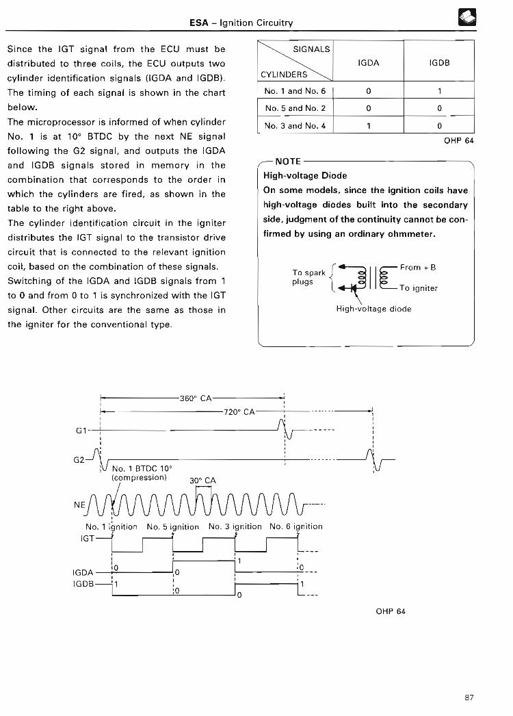
ESA - Ignition Circuitry
Since the IGT signal from the ECU must be
distributed to three coils, the ECU outputs two
cylinder identification signals (IGDA and IGDB) .
The timing of each signal is shown in the chart
below.
The microprocessor is informed of when cylinder
No. 1 is at 100 BTDC by the next NE signal
following the G2 signal, and outputs the IGDA
and IGDB signals stored in memory in the
combination that corresponds to the order in
which the cylinders are fired, as shown in the
table to the right above .
The cylinder identification circuit in the igniter
distributes the IGT signal to the transistor drive
circuit that is connected to the relevant ignition
coil, based on the combination of these signals .
Switching of the IGDA and IGDB signals from 1
to 0 and from 0 to 1 is synchronized with the IGT
signal . Other circuits are the same as those in
the igniter for the conventional type .
3600 CA
720° CA
G1
G2No. 1 BTDC 10 '(compression)
0
SIGNALS
CYLINDERS
IGDA IGDB
No . 1 and No . 6 0 1
No. 5 and No . 2 0 0
No. 3 and No . 4 1 0
OHP 64
/-IVV 1 C
High-voltage Diode
On some models, since the ignition coils have
high-voltage diodes built into the secondary
side, judgment of the continuity cannot be con-
firmed by using an ordinary ohmmeter .
To spar kplugs
From + B
LTo ignite ruHigh-voltage diod e
No . 1 ignition No . 5 ignition No . 3 ignition No . 6 ignitio n
IGT
,0Ir
OHP 64
87

3 . DIS (DIRECT IGNITION SYSTEM)
ESA - Ignition Circuitry
Similar to DLI, DIS is the system to distribute the high voltage directly to the spark plugs from ignition coils
without using a distributor . There are various types of current DIS systems, including those in which an igni-
tion coil is provided for each cylinder and those in which an ignition coil is provided for every two cylinders
(See Step 2, Vol . 3, "Ignition System") . The electrical circuitry shown here is for the type in which an igni-
tion coil is provided for each cylinder .
Igniter Engine ECU
Constantvoltagecircuit
Ignitionswitch
Battery
I
i iSpark Ignition
plugs coils
U
U
a)>
~
GT
GT
IGT z
GT o
Lock
preventioncircui t
Constancurrentcontrolcircuit
Dwell anglecontrolCircui t
Ignitiondelecting
circuit
F-•ITACH, lGFsignal outpucircuit
O
•TACH
2JZ-GTE ENGINE (May, 1993)
Control by the Engine ECU is basically the sam e
as that of an ordinary ESA . The difference is tha t
the Engine ECU has the same number of IGT IGT,ON
OFF ~signals as the number of ignition coils . IGT signals ON
are then sent to the igniter according to the igni-IGT5
OF F
tion sequence .IGT 3
IGT 6
IGT 2
IGT4
ON
OF F
ON
OF F
ON
OFF
ON
OF F
IGF* ONOFF
0mmmU0a
N E
Sensors
l
*The IGF signals in DIS is normally HI (ON) ,and turns to LO (OFF) during ignition .
IGF
88

ESA - Functions of Engine ECU
FUNCTIONS OF ENGINE ECU1 . IGNITION TIMING CONTRO L
Ignition timing control consists of two basic controls :
• Sta rt ing ignition contro l
When the engine is cranking, ignition occurs at a
certain fixed crankshaft angle, regardless of
engine operating conditions. This is called
"initial ignition timing angle" .
Initial ignition timing angl e
OHP 65
Initial ignition timing angl e
!4 01Actual ignition timing
OHP 6 5
REFERENCE
Note that, in after-start ignition control, each
type of correction differs depending on the
engine model .
Ignitiontimingcontrol
Starting ignition control Initial ignition timing angl e
Initial ignition timing angle
Basic ignition advance angl e
After-sta rt ignition control
• After-start ignition contro l
Various corrections are added to the initial
ignition timing angle and the basic ignition
advance angle during normal operation .
Correctiveignitionadvancecontrol
Warm-up correction
Over-temp. correction
Stable idling correction
EGR correction
Air-fuel ratio feedback correction
Knocking correction
Torque control correction
Other correction
Maximum and minimumadvance angle control
89

ESA - Functions of Engine ECU
The relationship between the major controls the REFERENC E
make up ignition timing control and the major The signals used for certain controls may
signals from each sensor is shown in the differ depending on the engine .
following table .
LLW
W
0 JxU
SIGNALS o d J P: (D 0 ~ U) LU ~ SeO O
~ > ZD (L LL Cn ¢ (n U) _j O~V
0Z
~ LLQ"'Z
ga z _Jz~ z
~ a OW(D H!
~ OQ ~
~Za Z0
j
~
u. O
IGNITION TIMING CONTROL Y O QF ~m a ~>
_J> C7 Z = CL
a
Z> O
V)O ~
0
Sta rt ing ignition control 0 0Basic ignition advance angle 0 0 0 0 0
~C Warm-up correction 0 0 0~ Over-temperature correction 0MC Stable idling correction 0 0 00YE
EGR correction 0 0 0 0 0t m_
~> Air-fuel ratio feedback correction 0 0 0m ° Knocking correction 0rooU c~ Torque control correction* 0 0 0 0
Torque control correction also uses the vehicle speed (SP2) signal . This signal is used to control the ECT . For furtherdetails, see Step 3, vol . 4 (ECT) .
90

ESA - Functions of Engine ECU
STARTING IGNITION CONTRO L
Starting ignition control is carried out once
immediately after input of the NE signal
following the G(G1 or G2) signal . This ignition
timing is called "initial ignition timing angle" .
For further details, see page 83.
During sta rt ing, when the engine speed is still
below a specified rpm (usually around 500 rpm),
since the intake manifold pressure (PIM) signal
or the intake air volume (VS, KS or VG) signal is
unstable, the ignition timing is fixed at the initial ig-
nition timing (which differs depending on the
engine model) . This initial ignition timing is set
directly by the back-up IC in the Engine ECU .
FRELEVANT SIGNALS
Crankshaft angle (G)
Engine speed (NE )
REFERENCE
In some engine models, the starter (STA)
signal is also used to inform the ECU that the
engine is being cranked.
Engine EC U
NE '""""
Initial ignition timing anglel signal generation circuit
11
AFTER-START IGNITION CONTRO L
After-start ignition control is carried out during
normal operation .
The various corrections (which are based on
signals from the relevant sensors) are added to
the initial ignition timing angle and to the basic
ignition advance angle (which is determined by
the intake manifold pressure signal or the intake
air volume signal, and by engine speed signal) :
Ignition timing = initial ignition timing angle
+ basic ignition advance angl e
+ corrective ignition advance
angle
During normal operation of after-start ignition
control, the ignition timing (IGT) signal
calculated by the microprocessor is output
through the back-up IC .
Engine ECU
OHP 65
IGTJUL
OHP 65
91

T Basic ignition advance angle
ESA - Functions of Engine EC U
The basic ignition advance angle in the ESA
system corresponds to the vacuum advance and
governor advance angles in conventional EFI .
Data on the optimal basic ignition advance angle
(which correspond to the engine speed and
intake manifold pressure or intake air volume)
are held in the memory of the Engine ECU .
IDLE CONTACT CLOSED (ON )
The ignition timing is advanced in accordance
with the engine speed when the idle contact
closes .
omCC ~
U C- f0
>COc om
Low-Engine speed
-RELEVANT SIGNALS
• Thrott le position (IDL)
• Engine speed (NE)
High
OHP 6 6
REFERENCE
In some engine models, the basic ignition ad-
vance angle changes (as shown by the dotted
line in the graph above) depending on whether
the air conditioner is on or off .
In addition, there are also models in which the
advance angle is "0" at the time of the stan-
dard idle speed .\1 i
IDLE CONTACT OPEN (OFF )
The Engine ECU determines the basic ignition
advance angle based on data stored in its
memory, and based on the intake manifold
pressure (or the intake air volume) and engine
speed .
In some engine models, two types of basic
ignition advance angle data are stored in
memory. One or the other of these two sets of
data is then used, depending on the fuel octane
rating (premium or regular) .
The driver can select the data to be used by
setting the fuel control switch or connector to
match the octane rating of the gasoline used .
In vehicles equipped with the fuel octane
judgment capability, the relevant data are
accessed automatically in accordance with the
knock (KNK) signal from the knock sensor (Se e
page 116) .
RELEVANT SIGNALS
• Intake manifold pressure (PIM) or intake air
volume (VS, KS or VG )
• Engine speed (NE )
• Throttle position (IDL )
• Fuel control switch or connector (R-P )
• Engine knocking (KNK)J
92

ESA - Functions of Engine ECU 4W~2 Corrective ignition advance contro l
WARM-UP CORRECTIO N
The ignition timing is advanced to improve
drivability when the coolant temperature is low .
In some engine models, this correction changes
the advance angle in accordance with the intake
manifold pressure or the intake air volume .
The ignition timing angle is advanced by
approximately 15° by this correction during
extremely cold weather .
OVER-TEMPERATURE CORRECTIO N
To prevent knocking and overheating, the
ignition timing is retarded when the coolant
temperature is extremely high .
The ignition timing angle is retarded a maximum
of approximately 5° by this correction .
0
-5
110*(230)
Coolant temperature °C ('F )*Depending on the engine models .
60*(140 )
Coolant temperature 'C ('F)*Depending on the engine models .
OHP 66
-RELEVANT SIGNAL S
• Coolant temperature (THW )
• Intake manifold pressure (PIM) or intake air
volume (VS, KS or VG )
REFERENCE
In some engine models, the throttle position
(IDL) signal or the engine speed ( NE) signal is
used as the relevant signal for this correction .
RELEVANT SIGNAL
Coolant temperature (THW)
OHP 66
REFERENCE
In some engine models, the following signals
are also used for this correction .
• Intake manifold pressure ( PIM) signal or
intake air volume (VS, KS or VG) signa l
• Engine speed (NE) signa l
• Throttle position (IDL) signal
etc .
93

ESA - Functions of Engine EC U
STABLE IDLING CORRECTIO N
When the engine speed during idling has fluc-
tuated from the target idle speed, the Engine ECU
adjusts the ignition timing to stabilize the engine
speed .
The ECU is constantly calculating the average
engine speed. If the engine speed falls below
the target speed, the ECU advances the ignition
timing by a predetermined angle . If the engine
speed rises above the target speed, the ECU
retards the ignition timing by a predetermined
angle. The ignition timing angle is changed a
maximum of approximately ±5° by this
correction.
This correction is not executed when the engine
exceeds a predetermined speed .
O f_
Difference from target idle speed
OHP 66
-RELEVANT SIGNALS
• Engine speed (NE )
• Throttle position (IDL)
• Vehicle speed (SPD )
REFERENCE
1 . In some engine models, the advance angl e
changes depending on whether the air
conditioner is on or off .
2 . In some engine models, this correction only
operates when the engine speed is below
the target engine speed .
EGR CORRECTIO N
When the EGR is operating and the IDL contact
is off, the ignition timing is advanced according
to the volume of the intake air and the engine
speed to improve drivability.
-RELEVANT SIGNAL S
• Intake manifold pressure ( PIM) or intake air
volume (VS, KS or VG )
• Engine speed (NE)
• Thrott le position (IDL and PSW or VTA)
94

ESA - Functions of Engine EC U
AIR-FUEL RATIO FEEDBACK CORRECTION(engines with oxygen sensor )
During air-fuel ratio feedback correction, the
engine speed varies according to the increase or
decrease in the fuel injection volume . The
engine is especially sensitive to changes in the
air-fuel ratio when it is idling, so stable idling is
ensured by advancing the ignition timing at this
time in order to match the fuel injection volume
of air-fuel ratio feedback correction .
The ignition timing angle is advanced a
maximum of approximately 5° by this correction .
This correction is not executed while the vehicle
is being driven .
-RELEVANT SIGNALS
• Oxygen sensor (OX)
• Thro tt le position (IDL)
• Vehicle speed (SPD)
KNOCKING CORRECTION
a
If engine knocking occurs, the knock sensor
converts the vibrations created by the knocking
into voltage signals and sends them to the
Engine ECU .
Distributo r
Spark plug
Igniter & coi l
Sensor
Engine EC U
wEngine knockingcorrectio n circuitry
OHP 67
The ECU judges whether the strength of the
knocking is at one of three levels, strong,
medium or weak, according to the strength of
the KNK signals, and changes the corrective
ignition retard angle accordingly . In other words,
if the knocking is strong, the ignition timing is
retarded a lot, while if knocking is Weak, it is
retarded only a li tt le .
When engine knocking stops, the ECU stops
retarding and begins advancing the ignition
timing by fixed angles a li tt le at a time .
This ignition timing advance continues until
engine knocking recurs, at which point the
ignition timing is again retarded .
The ignition timing angle is retarded a maximum
of approximately 10° by this correction .
Retarding of the ignition timing during knocking
is carried out within the knocking correction
range . In some engines, this means when the
engine is operating under a heavy load (vacuum
below approx. 26.7 kPa [200 mmHg, 7 .9 in .Hg]),
while in other engines, it covers vi rtually the full
engine load range .
95

ESA - Functions of Engine EC U
The ECU feeds back signals from the knock TORQUE CONTROL CORRECTIO Nsensor to correct the ignition timing as shown
below.
ENGINE KNOCKING
OCCURS
TIMING
ADVANCED
TIMING
RETARDE D
ENGINE KNOCKING
STOPS
OHP 67
Weak Engine knocking Strong
OHP 67
-RELEVANT SIGNAL -
• Engine knocking (KNK)
In the case of vehicles equipped with the ECT
(electronically-controlled transmission), each
clutch and brake in the planetary gear unit of the
transmission or transaxle generates shock to
some extent during shifting . In some models,
this shock is minimized by delaying the ignition
timing when gears are up- or down-shifted .
When gear shifting starts, the Engine ECU
retards the engine ignition timing to reduce the
engine torque .
As a result, the shock of engagement of the
clutches and brakes of the planetary gear unit is
reduced and the gear shift change is performed
smoothly .
The ignition timing angle is retarded a maximum
of approximately 200 by this correction .
This correction is not performed when the
coolant temperature or battery voltage is below
a predetermined level .
-RELEVANT SIGNALS
• Engine speed (NE)
• Thrott le position (VTA )
• Coolant temperature (THW)
• Ba ttery voltage (+B)
96

ESA - Functions of Engine EC U
OTHER CORRECTIONS
Engines have been developed with the following
corrections added to the ESA system (in addition
to the various corrections explained so far), in
order to adjust the ignition timing with
extremely fine precision .
a . Transition Correctio n
During the transition (change) from deceleration
to acceleration, the ignition timing is either
advanced or retarded temporarily in accordance
with the acceleration .
b . Cruise Control Correction
When driving downhill under cruise control, in
order to provide smooth cruise control operation
and minimize changes in engine torque caused
by fuel cut-off due to engine braking, a signal is
sent from the Cruise Control ECU to the Engine
ECU to retard the ignition timing .
c. Traction Control Correctio n
This retards the ignition timing, thus lowering
the torque output by the engine, when the
coolant temperature is above a predetermined
temperature and the traction control system is
operating .
d . ACIS (Acoustic Control Induction System)Correction
When the engine speed rises above a
predetermined level, the ACIS operates . At that
time, the Engine ECU advances the ignition
timing simultaneously, thus improving output .
See page 120 for details on the ACIS .
e. Intercooler Failure Correctio n
This correction retards the ignition timing if the
intercooler fail signal goes on .
MAXIMUM AND MINIMUM ADVANCE ANGLECONTRO L
If the ignition timing (initial ignition timing +
basic ignition advance angle + corrective ignition
advance angle) becomes abnormal, engine
operation will be adversely affected .
To prevent this, the Engine ECU controls the
actual ignition angle (ignition timing) so that the
sum of the basic ignition advance angle and
corrective ignition advance angle cannot be
greater or less than certain values .
These values are :
MAX. ADVANCE ANGLE 350 -450
MIN . ADVANCE ANGLE -10° - 0°
Advance angle = Basic ignition advance angl e
+ corrective ignition advance
angle
97

ESA - Functions of Engine EC U
2 . IGNITION TIMING ADJUSTMENT
The angle to which the ignition timing is set
during ignition timing adjustment is called the
"standard ignition timing ." It consists of the
initial ignition timing (See page 83), plus a fixed
ignition advance angle (a value that is stored in
the ECU and output during timing adjustment
regardless of the corrections, etc ., that are used
during normal vehicle operation) .
Initial ignition timing angl e
Fixed ignition advanceangle
Standard ignitiontiming angle OHP 68
Ignition timing adjustment is carried out as
follows :
1) Set the standard ignition timing by
connecting terminal Ti (or TEi) of the check
connector or TDCL with terminal Ei, with the
idle contacts on . This will cause the standard
ignition timing signal to be output from the
back-up IC in the same way as during after-
start ignition control (See page 91) .
Check connectorTorTE1 E l
TDCL
OHP 68
SST El TE1
OHP 68
The standard ignition timing differs
depending on the engine model, as shown in
the following table . When tuning up the
engine, refer to the repair manual for the
relevant engine .
FIXEDENGINE
INITIALIGNITION
STANDAR D
IGNITION IGNITIONMODEL ADVANC E
TIMING TIMIN GANGLE
Type 1 100 BTDC 0° BTDC 100 BTDC
Type 2 5° BTDC 50 BTDC 10° BTDC
Type 3 70 BTDC 0° BTDC 7° BTDC
OHP 68
2) If the standard ignition timing is not as
specified above, adjust it .
/.-- NOTE
1 . Even if terminal T1 or TE1 and terminal E1
are connected, the ignition timing will not
be fixed at the standard ignition timing
unless the idle contacts are on .
2. Since the G and NE signal generators are fix-
ed in recent models, there are cases in
which ignition timing cannot be adjusted .
98

ISC - Genera l
ISC (IDLE SPEED CONTROL)
GENERAL
The ISC system controls the idle speed by means
of the ISC valve to change the volume of air
flowing through the throttle valve bypass in
accordance with signals from the ECU.
There are four types of ISC valve, as follows :
• Stepper motor typ e
• Rota ry solenoid type
• Duty-control ACV (air control valve) type
• On-off control VSV (vacuum switching valve)
type
Air cleaner
Iri
Ignitionswitch
Battery I i~
Engine ECU
Sensors
BASIC CONSTRUCTION OF ISC
®
The control functions in the ISC system differ
depending on the engine.
The power steering idle-up mechanism is
controlled by a separate idle-up device (see Step
2, vol . 11 ["Steering System"] for more details) .
Since the volume of air passed through the duty-
control ACV type ISC valve and the on-off
control VSV type ISC valve is small, a separate
air valve for controlling the greater amount of
air needed during cold starting is also provided .
See page 65 for details on this air valve .
OHP 69
99

® ISC - Genera l
The following table shows the specifications for specifications for each engine in the APPENDIX
the 4A-FE engine . Items with circles in the section (page 188) at the back of this manual .
"APPENDIX" column are included in th e
PAG E
ISC (IDLE SPEED CONTROL) (THIS ITEM REMARK APPENDIXMANUAL)
Stepper motor type 10 1
Rotary solenoid type 102ISC valve
Duty-control ACV type 104
On-Off control VSV type 104
Starting set-up 10 5
After-start control 106
Warm-up (fast-idle) control 106Stepper
Feedback control 107motor type
ISC valve Engine speed change 107estimate contro l
Electrical load idle-up 107contro l
Other controls 107
Start ing control 108 ~
Warm-up (fast-idle) 108o Rotary contro lsolenoid
Feedback control 108 L7type ISCvalve Engine speed change 109
estimate contro l
Other controls 109
Starting control 11 0
Duty-control Feedback control 11 0ACV type Engine speed change 1 1 0ISC valve estimate contro l
Constant duty control 11 0
On-off control VSV type ISC valve 11 1
*Specifications for Carolla AE101 4A-FE engine (Apr ., 1992 )
100

ISC - ISC Valve
ISC VALVE
1 . STEPPER MOTOR TYPE
The ISC valve is mounted on the air intake
chamber or throttle body. In order to control the
speed at which the engine idles, it increases or
decreases (based upon signals from the Engine
ECU) the amount of intake air that is allowed to
bypass the throttle valve .
The idle speed adjusting screw* is set to the fully
closed position at the factory, because the idle
speed is controlled by the ISC valve .
The use of the idle speed adjusting screw has
been discontinued in recent models .
Air flow meterIdle speed adjusting screw *
EngineECU
ISCvalve
Thro tt le valve
To cylinder s
OHP 70
CONSTRUCTIO N
A stepper motor is built into the ISC valve. This
motor rotates the rotor clockwise or
counterclockwise, moving the valve in or out .
This in turn increases or decreases the clearance
between the valve and valve seat, regulating
the amount of air that is allowed to pass
through . The ISC valve has 125 steps from the
fully closed to the fully open position .
Since the air flow capacity of the stepper motor
type ISC valve is large, it is also used for
controlling fast idle . It is not necessary to use it
in combination with an air valve .
Rotor
Stator
®
To air intake♦ chamber
Valve seat
Valve shaft
Stopper plat e
OHP 70
itFrom air flow mete r
Small - Number of steps-Large
OHP 7 0
• Rotor . . . constructed of a 16-pole perma-
nent magnet . (The number of poles
differs depending on the engine . )
• Stator . . . two sets of 16-pole cores, each of
which is staggered by half a pitch
in relation to the other . Two coils
are wound around each core, each
coil being wound in opposite
directions . (The number of poles
differs depending on the engine . )
OHP 7 0
OPERATIO N
Current flows through one of the four coils of
the stator in turn in accordance with the output
from the ECU . The flow of current in coil S1 is as
shown in the following illustration :
101

©
S1
131S3
S2
B2
S4
Coils Stato r
Pole pa tternof stator
N
MOVEMENT OF VALVE
ISC - ISC Valve
I1
OHP 7 1
The valve shaft is screwed into the rotor. The
shaft is prevented from turning by means of a
stopper plate, so it moves in and out as the rotor
rotates. This controls the clearance between the
valve and valve seat, decreasing or increasing it
to regulate the amount of air allowed through
the bypass .
ROTATION OF ROTO R
The direction of rotation of the rotor is reversed
by changing the order in which current is
allowed to pass through the four coils . If the
stator and rotor are the 16-pole type, the rotor is
rotated about 11° (1/32 of a revolution) each
time current passes through the coils .
When the rotor rotates one step, the positional
relationship shown in the figure below develops,
and the stator coils become excited . Since the N
poles tend to be attracted to the S poles in the
stator and rotor, and since like poles in the
stator and rotor tend to repel each other, the
rotor rotates one step .
Stato r
RotorV..(_C.!!!_!'
Stato r
Rotor
102
N
1IN
S
s
S
1 1S
N
N
S
N
N
~- 1/32 revolution
s
_L > Repulsion
t* Attraction
S
S
N S
OHP 71
2. ROTARY SOLENOID TYPE
The ISC valve is mounted on the throttle body,
and intake air that bypasses the throttle valve
passes through it .
The ISC valve is operated by signals from the
Engine ECU, and controls the amount of intake
air that is allowed to bypass the throttle valve .
Although older models still had an idle speed ad-
justing screw, its use has been discontinued in re-
cent models .
Airintake
Thrott le valve chambe r
To cylinde r
OHP 7 2
The ISC valve is a small, lightweight rotary
solenoid type valve .
Since the air flow capacity of the rotary solenoid
type ISC valve is high, it is also used for
controlling fast idle . It is not necessary to use it
in combination with an air valve .

ISC - ISC Valve
Bypass air passag e
A'
OHP 7 2
From To air intakeair cleaner chambe r
~ L~
;~
Bypass po rtO
~
Valveup
✓ alve
Cross-section A-A'
OHP 72
• Permanent magnet
Located at the end of the valve shaft, the
cylindrical permanent magnet rotates when
its two poles are repelled by the magnetism
exe rted by coils Ti and T2 .
• Valve
Anchored to the midsection of the valve
shaft, the valve controls the amount of air
passing through the bypass port, revolving
on the shaft together with the permanent
magnet .
®
• Coils (Ti and T2 )
Opposing each other and surrounding the
permanent magnet, the two coils act as
electromagnets that exert north-polarity
magnetic force on the sides facing the
permanent magnet when the ECU generates
a duty signal . The ECU thus causes the
permanent magnet to rotate, controlling the
magnetic intensity of the field produced by
the coils .
• Bimetallic strip assembl y
The bimetallic strip, similar to the one found
in a regular carburetor assembly, detects
changes in coolant temperature via the valve
body.
The guard attached to one end of the
bimetallic strip senses the position of the
valve shaft lever running through the notch
in the guard : the lever will not trigger
bimetallic strip operation as long as the ISC
system is operating normally, i .e ., as long as
the bimetallic strip does not contact the
notched section on the guard . This
mechanism acts as a fail-safe device that
prevents the engine from running at
excessively high or low speeds due to a
defect in the ISC system's electrical circuitry .
Coil T2
Valve shaft
' Bimetal strip
OHP 72
103

aNOTE -
Duty Ratio
ISC - ISC Valv e
The "duty ratio" is the ratio of the interval
during which current flows to the interval
during which current does not flow in one
cycle of a signal . The figure below shows the
time in one cycle during which current flows
and does not flow .
A: Current flows (on )
B: Current does not flow (off )
(On )1
0(Off) B
Duty ratio (% )
= A+AB x 100
1 cycl e
LOW DUTY RATIO HIGH DUTY RATIO(On) (On)1 n n n 1
0 ~
(Off)
~ 0 J U u U
(Off)OHP 73
3 . DUTY-CONTROL ACV TYPE
The construction of this type of ISC valve is as
shown in the following figure . While current
flows according to signals from the Engine ECU,
the coil becomes excited and the valve moves .
This changes the gap between the solenoid
valve and the valve body, controlling the idle
speed. (Note, however, that the fast-idle speed
is controlled using an air valve . )
From air cleaner
♦
♦To air intake chambe r
OHP 73
In actual operation, current to the coil is
switched on and off each 100 msec ., so the
position of the solenoid valve is determined by
the proportion of time that the signal is on as
compared to the time it is off (i .e ., by the duty
ratio) . In other words, the valve opens wider the
longer current flows to the coil .
4 . ON-OFF CONTROL VSV TYPE
The construction of this type of ISC valve is as
shown in the figure below . Signals from the
Engine ECU cause current to flow to the coil .
This excites the coil, which opens the valve,
increasing the idle speed by approximately 100
rpm . (Fast-idle speed is controlled using an air
valve .)
Solenoid coil
From aircleaner
~ To air intakechambe r
OHP 73
104

ISC - Functions of Engine EC U
FUNCTIONS OF ENGINE EC U
1 . STEPPER MOTOR TYPE ISC VALVE
This type of ISC valve is connected to the Engine opening angle and vehicle speed signals that the
ECU as shown in the following diagram . Target engine is idling, it switches on Tr, to Tr4, in that
idling speeds for each coolant temperature and order, in accordance with the output of those
air conditioner operating state are stored in the signals . This sends current to the ISC valve coil,
ECU's memory. until the target idling speed is reached.
When the ECU judges from the throttle valv e
Engine ECU
BATT
Battery
EFI main relayr- Microprocesso r
flB+ *
IIbIIx--I
Ignition switch
-REL
IGSW
E1
Main relaycontrol circui t
\1
* Some models onl y
STARTING SET-UP
When the engine is stopped (no NE signal to the
ECU), the ISC valve opens fully (to the 125th
step) to improve sta rtability when the engine is
resta rted .
• Main Relay (ISC Valve Set-up) Contro l
The supply of power to the ECU and ISC
valve must be continued for a few moments,
even after the ignition switch is turned off,
in order to allow the ISC valve to be set up
(fully opened) for the next engine start-up .
Therefore, the ECU outputs 12 V from the M-
REL terminal until the ISC valve is set up, in
order to keep the main relay on . Once set-up
is complete, it cuts off the flow of current to
the main relay coil .
OHP 74
CONDITIONSCURRENT TOMAIN RELAY
Ignition switch on ON
Ignition switch off O N(ISC valve set-up is Icomplete) OF F
RELEVANT SIGNAL
-*Engine speed (NE )
/-NOTE
Stepper motor type ISC valves will enter a hold
state when the power is interrupted . As a
result, they are stopped at the position where
they were when the power was interrupted .
105

ISC - Functions of Engine EC U
AFTER-START CONTRO L
Due to the previous set-up of the ISC valve, the
amount of air passing through the ISC valve
during starting is the maximum amount possible .
This allows the engine to start easily .
However, after the engine has started, its speed
would rise too high if the ISC valve were kept
fully open, so when the engine reaches a certain
speed (this speed being determined by the
temperature of the coolant) during or after
starting, the ECU begins sending signals to the
ISC valve, causing it to close from step 125 (fully
open) to a point determined by the coolant
temperature .
For example, if the coolant temperature is 20°C
(68°F) during starting, the ISC valve will
gradually close from the fully-open position
(step 125, or point A) to point B when engine
speed reaches the predetermined level .
125A
A-B: After-sta rt contro l
20(68 )
Coolant temperature °C (°F )
RELEVANT SIGNALS• Engine speed (NE )
• Coolant temperature (THW)
• Throttle position (IDL )
• Vehicle speed (SPD)
OHP 75
WARM-UP (FAST-IDLE) CONTRO L
As the coolant warms up, the ISC valve
continues to gradually close from the point to
which it closed during starting . When the coolant
temperature reaches about 80°C (176°F), fast-
idle control by the ISC valve ends .
125A
---------- -------------\ A-B: After-sta rt contro l
B-C: Warm-up contro l
20 80(68) (176)
Coolant temperature °C (°F)
OHP 75
r-- RELEVANT SIGNALS
Engine speed (NE )Coolant temperature (THW)
Throttle position (IDL)
Vehicle speed (SPD )
106

ISC - Functions of Engine ECU
FEEDBACK CONTROL
Feedback control is carried out when the idle
contact is on, the vehicle speed is below a
predetermined speed, and the coolant
temperature is about 80°C (176°F) .
If the difference between the actual engine
speed and the target speed stored in the
memory of the ECU is more than 20 rpm, the
ECU sends a signal to the ISC valve, telling it to
increase or decrease the volume of air passing
through the bypass passage so that the actual
engine speed will match the target speed .
125A-B: After-sta rt control
B-C : Warm-up control
C-D: Feedback control
11kENGINE SPEED CHANGE ESTIMATE CONTRO L
Immediately after the neutral start switch or air
conditioner switch is operated, the engine load
also changes . To prevent the engine speed from
changing because of this, the ECU sends signals
to the ISC valve to open or close it by a fixed
amount before changes in the engine speed can
occur .
- RELEVANT SIGNALS
• Engine speed (NE )
• Neutral sta rt switch (NSW)
• Thrott le position (IDL)
• Vehicle speed (SPD)
• Air conditioner (A/C )
ELECTRICAL LOAD IDLE-UP CONTROL
20 80(68) (176)
A------------------ ----------------
Coolant temperature °C (°F) OHP 75
Target speeds also differ depending on engine
conditions, such as whether the neutral start
switch is on or off, and whether the air
conditioner switch is on or off .
NOTE
Stepper motor type ISC valves also control idle
up of the air conditioner.
RELEVANT SIGNALS• Engine speed (NE)
• Throttle position (IDL)
• Vehicle speed (SPD )
• Coolant temperature (THW)
• Air conditioner (A/C )
• Neutral sta rt switch (NSW)
Since the generating capacity of the alternator in-
creases when an electrical load is applied, the
Engine ECU opens the step position by a certain
number of steps in order to increase the idle speed
when there has been a voltage drop at the + B ter-
minal or IGSW terminal or when a signal has been
applied to the LP terminal, DFG terminal or ELS ter-
minal .
RELEVANT SIGNALS
• Electrical load (LP, DFG, or ELS)
• Engine speed (NE)
• Throttle position (IDL)
• Vehicle speed (SPD )
OTHER CONTROLS
In addition to the above controls, some engines
are also provided with a control in which the ISC
valve operates like a dashpot during
deceleration, and a control in which the ISC
valve opens slightly when the oil pressure
switch goes on .
107
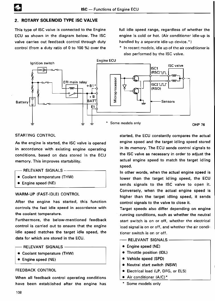
ISC - Functions of Engine ECU
2. ROTARY SOLENOID TYPE ISC VALV E
This type of ISC valve is connected to the Engine
ECU as shown in the diagram below. The ISC
valve carries out feedback control through duty
control (from a duty ratio of 0 to 100 %) over the
Battery
full idle speed range, regardless of whether the
engine is cold or hot. (Air conditioner idle-up is
handled by a separate idle-up device .* )
In recent models, idle up of the air conditioner is
also performed by the ISC valve .
OHP 76
STARTING CONTRO L
As the engine is started, the ISC valve is opened
in accordance with existing engine operating
conditions, based on data stored in the ECU
memory. This improves startability .
- RELEVANT SIGNAL S
• Coolant temperature (THW)
• Engine speed (NE)
WARM-UP (FAST-IDLE) CONTRO L
After the engine has started, this function
controls the fast idle speed in accordance with
the coolant temperature .
Fu rthermore, the below-mentioned feedback
control is carried out to ensure that the engine
idle speed matches the target idle speed, the
data for which are stored in the ECU .
FRELEVANT SIGNALS
Coolant temperature (THW)
Engine speed (NE )
FEEDBACK CONTROL
When all feedback control operating conditions
have been established after the engine has
started, the ECU constantly compares the actual
engine speed and the target idling speed stored
in its memory . The ECU sends control signals to
the ISC valve as necessa ry in order to adjust the
actual engine speed to match the target idling
speed .
In other words, when the actual engine speed is
lower than the target idling speed, the ECU
sends signals to the ISC valve to open it .
Conversely, when the actual engine speed is
higher than the target idling speed, it sends
control signals to the valve to close it .
Target speeds also differ depending on engine
running conditions, such as whether the neutral
start switch is on or off, whether the electrical
load signal is on or off, and whether the air condi-
tioner switch is on or off .
RELEVANT SIGNALS
• Engine speed (NE)
• Throttle position (IDL)
• Vehicle speed (SPD)
• Neutral sta rt switch (NSW)
• Electrical load (LP, DFG, or ELS)
• Air conditioner (A/C) *
* Some models onl y
108
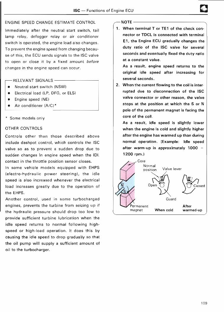
ISC - Functions of Engine EC U
ENGINE SPEED CHANGE ESTIMATE CONTROL
Immediately after the neutral start switch, tail
lamp relay, defogger relay or air conditioner
switch is operated, the engine load also changes .
To prevent the engine speed from changing becau-
se of this, the ECU sends signals to the ISC valve
to open or close it by a fixed amount before
changes in the engine speed can occur .
RELEVANT SIGNALS
Neutral start switch (NSW)
Electrical load (LP, DFG, or ELS )
• Engine speed (NE )
• Air conditioner (A/C) *
* Some models onl y
OTHER CONTROL S
Controls other than those described above
include dashpot control, which controls the ISC
valve so as to prevent a sudden drop due to
sudden changes in engine speed when the IDL
contact in the throttle position sensor closes .
In some vehicle models equipped with EHPS
(electro-hydraulic power steering), the idle
speed is also increased whenever the electrical
load increases greatly due to the operation of
the EHPS .
Another control, used in some turbocharged
engines, prevents the turbine from seizing up if
the hydraulic pressure should drop too low to
provide sufficient turbine lubrication when the
idle speed returns to normal following high-
speed or high-load operation . It does this by
causing the idle speed to drop gradually so that
the oil pump will supply a sufficient amount of
oil to the turbocharger .
®
~ 1 V V 1 C
1 . When terminal T or TE1 of the check con-
nector or TDCL is connected with terminal
E1, the Engine ECU gradually changes the
duty ratio of the ISC valve for several
seconds and eventually fixed the duty ratio
at a constant value .
As a result, engine speed returns to the
original idle speed after increasing for
several seconds .
2. When the current flowing to the coil is inter-
rupted due to disconnection of the ISC
valve connector or other reason, the valve
stops at the position at which the S or N
pole of the permanent magnet is facing the
core of the coil .
As a result, idle speed is slightly lower
when the engine is cold and slightly higher
after the engine has warmed up than during
normal operation . (Example : Idle speed
after warm-up is approximately 1000 -
1200 rpm. )
Core
Normalposition Valve lever
n. W/
Guard
Permanent Aftermagnet When cold warmed-up
109
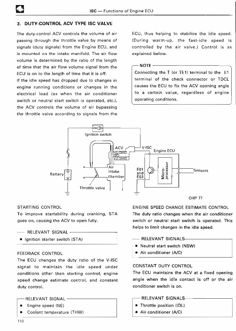
❑ ISC - Functions of Engine ECU
3 . DUTY-CONTROL ACV TYPE ISC VALVE
The duty-control ACV controls the volume of air
passing through the throttle valve by means of
signals (duty signals) from the Engine ECU, and
is mounted on the intake manifold . The air flow
volume is determined by the ratio of the length
of time that the air flow volume signal from the
ECU is on to the length of time that it is off .
If the idle speed has dropped due to changes in
engine running conditions or changes in the
electrical load (as when the air conditioner
switch or neutral start switch is operated, etc .),
the ACV controls the volume of air bypassing
the throttle valve according to signals from the
Battery
ECU, thus helping to stabilize the idle speed .
(During warm-up, the fast-idle speed is
controlled by the air valve .) Control is as
explained below .
NOTE
Connecting the T (or TE1) terminal to the El
terminal of the check connector or TDCL
causes the ECU to fix the ACV opening angle
to a certain value, regardless of engine
operating conditions .
OHP 77
STARTING CONTRO L
To improve startability during cranking, STA
goes on, causing the ACV to open fully .
RELEVANT SIGNA L
• Ignition starter switch (STA )
FEEDBACK CONTRO L
The ECU changes the duty ratio of the V-ISC
signal to maintain the idle speed under
conditions other than starting control, engine
speed change estimate control, and constant
duty control .
-RELEVANT SIGNAL
• Engine speed (NE )
• Coolant temperature (THW)
ENGINE SPEED CHANGE ESTIMATE CONTROL
The duty ratio changes when the air conditioner
switch or neutral start switch is operated . This
helps to limit changes in the idle speed .
- RELEVANT SIGNAL S
• Neutral sta rt switch (NSW)
• Air conditioner (A/C )
CONSTANT DUTY CONTROL
The ECU maintains the ACV at a fixed opening
angle when the idle contact is off or the air
conditioner switch is on .
RELEVANT SIGNALS
• Throttle position (IDL)
• Air conditioner (A/C )
110

ISC - Functions of Engine EC U
4. ON-OFF CONTROL VSV TYPE ISC VALV E
The Engine ECU sends signals to the VSV, in
accordance with signals from various sensors, to
cause the engine to idle at the appropriate
speed .
Battery
During warm-up, the fast-idle speed is
controlled by the air valve .
The following diagram shows one example of
connections between the VSV and ECU .
CONDITIONS FOR VSV OPERATION
a . Off to On
• When the engine is cranking and immediately
after starting.
• When engine speed falls below a
predetermined rpm (depending on the neutral
sta rt switch signal) with the idle contact on* .
• Several seconds after shifting from "P" or
"N" into any other range with the idle contact
on (A/T vehicles) .*
• The light control switch is turned on .
• The rear window defogger switch is turne d
on .
* The VSV stays off under this condition if check
terminals T or TE1 is connected to El .
However, if the light control switch or rear win-
dow defogger switch is turned on, the VSV
goes on .
OHP 78
b . On to Off
• When a predetermined period of time has
elapsed after the engine has started .
• When engine speed rises above a
predetermined rpm (depending on the neutral
start switch signal) with the idle contact on
and the A/C magnetic clutch disengaged .
• After a set time has elapsed after the
transmission is shifted from "P" or "N" into
any other range and the engine speed is
above a predetermined rpm with the idle
contact on and the A/C magnetic clutch
disengaged (A/T vehicles) .
• The light control switch is turned off.
• The rear window defogger switch is turned
off .
111

W
NOTE
ISC - Functions of Engine EC U
Learned Contro l
Besides the previously mentioned control, learn-
ed control is also used for control of the ISC
valve .
Normally, the Engine ECU controls the idle
speed by changing the ISC valve position .
However, since the engine's running condi-
tions change over time, the idle speed also
changes (even though the valve positions re-
main the same) .
So through feedback control, the Engine ECU
outputs ISC signals to return the idle speed to
the target level . The ISC valve position when
the target speed is reached is stored in back-up
memory, and is used thereafter in idling . This is
known as learned control .
If all power to the Engine ECU is cut off due to
the EFI fuse or STOP fuse being removed or a
battery cable being disconnected, the learned
value stored in back-up memory will be erased .
Therefore, when the engine is restarted, the
ISC valve position is set at the initial value
stored in memory .
At this time, the idle speed may not be the
same as the target speed, but when the engine
warms up and feedback control starts, it will
gradually approach the target speed .
112

OTHER CONTROL SYSTEMS - Genera l
OTHER CONTROL SYSTEM S
GENERAL
Some TCCS type engine control systems include As with the systems described up to this point,
not only the EFI, ESA, and ISC systems these systems are controlled by the Engine ECU .
explained so far, but also (depending on the The following table shows the specifications for
engine model) the systems explained in the the 4A-FE engine .
following pages .
SYSTEMSPAG E(THI SMANUAL)
ITEM" REMAR K
ECT OD cut-off control system 11 4
Oxygen sensor heater control system 114 O
Lean mixture sensor heater control system 11 4
Cut-off control 115 L~Air conditione rcontrol system Magnetic clutc h
relay control11 5
EGR cut-off control system 116 With EG R
Fuel octane judgment 11 6SCV (swirl control valve) system 11 7
ACIS (acoustic control Type 1 120
induction system) Type 2 122
T-VIS (Toyota-variable induction system) 124
Turbocharging pressure control system 12 7
Supercharger control system 12 8
EHPS (electro-hydraulic power steering )control system
12 8
AS (air suction) control system 12 9
Al (air injection) control system 12 9
* Specifications for Corolla 4A-FE engine (Apr ., 1992)
113
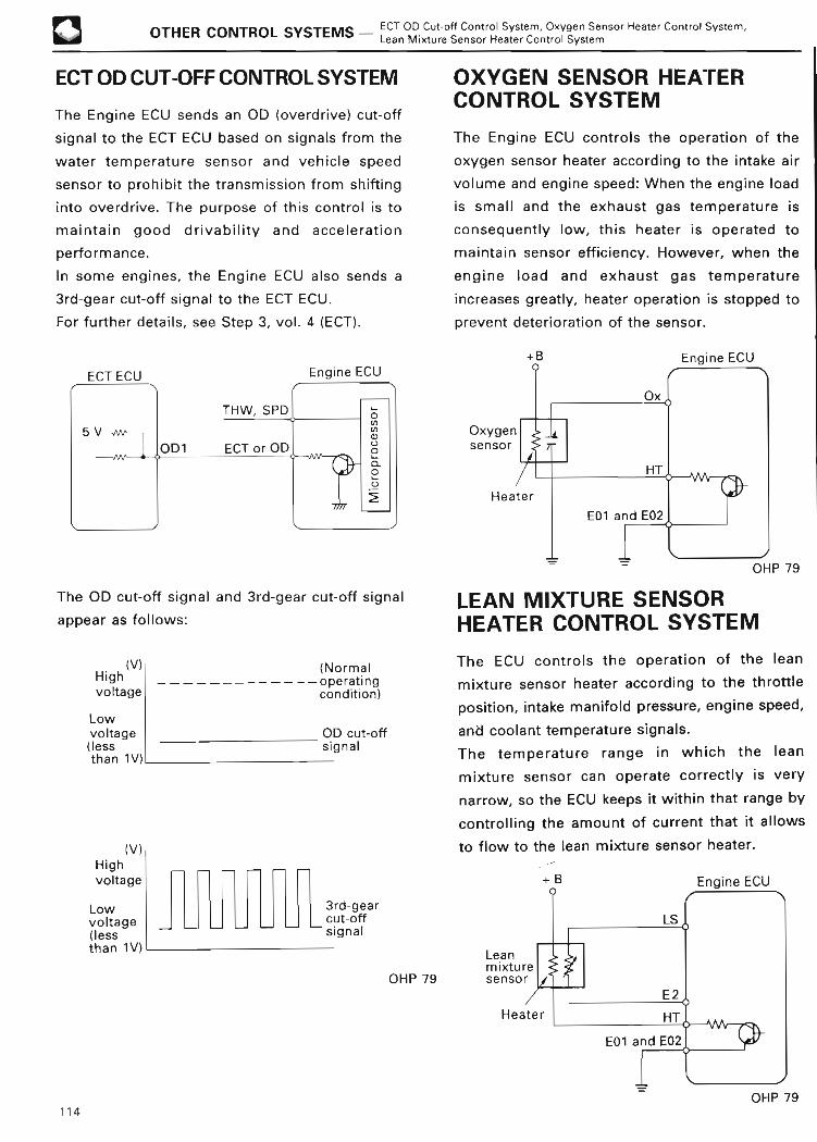
13OTHER CONTROL SYSTEMS - ECT OD Cut-off Control System, Oxygen Sensor Heater Control System,
Lean Mixture Sensor Heater Control Syste m
ECT OD CUT-OFF CONTROL SYSTEM
The Engine ECU sends an OD (overdrive) cut-off
signal to the ECT ECU based on signals from the
water temperature sensor and vehicle speed
sensor to prohibit the transmission from shifting
into overdrive. The purpose of this control is to
maintain good drivability and acceleration
performance .
In some engines, the Engine ECU also sends a
3rd-gear cut-off signal to the ECT ECU .
For fu rther details, see Step 3, vol . 4 (ECT) .
ECT ECU Engine ECU
OXYGEN SENSOR HEATERCONTROL SYSTE M
The Engine ECU controls the operation of the
oxygen sensor heater according to the intake air
volume and engine speed : When the engine load
is small and the exhaust gas temperature is
consequently low, this heater is operated to
maintain sensor efficiency . However, when the
engine load and exhaust gas temperature
increases greatly, heater operation is stopped to
prevent deterioration of the sensor.
Engine EC U
Oxygen
sensor
Heater
HT
E01 and E02
JOHP 7 9
The OD cut-off signal and 3rd-gear cut-off signal
appear as follows :
(V)Hig hvoltag e
Lowvoltage(lessthan 1V )
(V)Hig hvoltage
Lowvoltage(lessthan 1V)
(Normaloperatingcondition )
OD cut-offsigna l
L3rd-gearcut-offsignal
OHP 79
LEAN MIXTURE SENSORHEATER CONTROL SYSTE M
The ECU controls the operation of the lean
mixture sensor heater according to the throttle
position, intake manifold pressure, engine speed,
and coolant temperature signals .
The temperature range in which the lean
mixture sensor can operate correctly is very
narrow, so the ECU keeps it within that range by
controlling the amount of current that it allows
to flow to the lean mixture sensor heater .
114 OHP 79

OTHER CONTROL SYSTEMS - Air Conditioner Control System 0AIR CONDITIONER CONTROL SYSTE M
1 . CUT-OFF CONTROL 2 . MAGNETIC CLUTCH RELAYCONTRO L
The Engine ECU sends a signal (ACT) to the air
conditioner amplifier to disengage the air
conditioner compressor magnetic clutch in order
to stop operation of the air conditioning at
certain engine speeds, intake manifold pressures
(or intake air volumes), vehicle speeds and
throttle valve opening angles .
The air conditioner is turned off during quick
acceleration from low engine speeds (depending
on the vehicle speed, throttle valve position, and
intake manifold pressure or intake air volume) .
This helps maintain good acceleration
performance .
The air conditioner is also turned off when the
engine is idling at speed below a predetermined
rpm . This prevents the engine from stalling .
In some engine models, magnetic clutch
operation is also delayed for a predetermined
length of time after the air conditioner switch is
turned on. During this time, the Engine ECU
opens the ISC valve to offset the drop in the
engine speed due to the operation of the air
conditioner compressor . This prevents the idle
speed from dropping .
This latter control function is called the "air
conditioner compressor delay control" .
+B
This air conditioner control function differs from
the previously-mentioned type in that the
Engine ECU controls the magnetic clutch relay
directly .
When the Engine ECU detects the air conditioner
(A/C) signal from the air conditioner control
assembly, but does not detect the requisite air
conditioner cut-off conditions from various
sensors (see cut-off control to the left), this ECU
outputs a magnetic clutch (ACMG) signal to the
magnetic clutch relay, turning it on . As a result,
the magnetic clutch goes on and the air
conditioner compressor operates .
This air conditioner control function is also
provided with an air compressor delay control .
The operation of this is the same as that in th e
air conditioner cut-off control function .
+B
OHP 80
OHP 80115

© OTHER CONTROL SYSTEMS - EGR Cut-off Control System, Fuel Octane Judgmen t
EGR CUT-OFF CONTROLSYSTEM
This system actuates the VSV, which therefore
causes atmospheric air instead of intake
manifold vacuum to act on the EGR (exhaust gas
recirculation) vacuum modulator . This shuts off
the EGR to maintain drivability when the engine
coolant is cold or during high-speed driving etc .
OPERATION
The Engine ECU actuates the VSV, shutting off
the EGR when the coolant temperature is below
a predetermined temperature or when the
engine speed is above a set speed (roughly
4,000 to 4,500 rpm), to maintain drivability . The
ECU also actuates the VSV to shut off the EGR
when the intake air volume is above a
predetermined level or when the fuel cut-off
function is on in order to maintain EGR valve
durability .Thrott le valv e
lEGR vsv
~-.n, .+~ ~ i ~ . .,~
EGR valve
Airintakechamber
iSensors Exhaust gas
EGR ' ECU
S
Battery
OHP 8 1
REFERENCE
Some recent models use stepper motor type
EGR valves . An EGR vacuum modulator and
VSV are not provided in this system . The
Engine ECU controls EGR volume and cut-off .
In addition, when current is not applied to the
EGR valve, the valve is fully closed by the force
of a return spring .
Exhaust gas
FUEL OCTANE JUDGMEN T
The Engine ECU in some engine models
determines the octane rating of the gasoline
being used (whether it is "premium" or
"regular") according to engine knocking signals
from the knock sensor .
OPERATIO N
The ECU judges whether the gasoline is
"premium" or " regular" based on the retard
angle of the ignition timing, which is determined
by the strength of engine knocking when the
coolant temperature is above a predetermined
temperature . It judges the gasoline to be
"regular" when the engine knocks severely an d
the retard angle is larger than a predetermined
value. It judges the gasoline to be "premium"
when the engine knocks only mildly and the
retard angle is smaller than a predetermined
value . The ECU stores the result of this
judgment until it judges that the octane rating of
the gasoline has changed .
116

OTHER CONTROL SYSTEMS - SCV System
SCV (SWIRL CONTROL VALVE) SYSTE M
The intake port has been divided longitudinally
into two passages as shown in the following
illustration .
The swirl control valve, which is opened and
closed by the intake manifold vacuum, is
mounted in passage ;A .
Exhaust valve
Swirl control ~ Intake valv evalve (closed)
®
When the engine is running under a light load or
below a certain rpm, this valve closes, creating a
powerful swirl . This increases combustion
efficiency, thereby improving fuel economy .
Under a heavy load or over a certain rpm, the
valve opens, increasing intake efficiency, and
thus improving engine output .
A swirl control valve is provided in the intake
port of each cylinder .
Swirl control lin k
Intakeport
Passage B
Passage B
OHP 82
OHP 82
Thrott lepositionsensor
Manifol d
pressure
sensor valve
Swirl control valve OHP 82
117

rr
ACIS (ACOUSTIC CONTROL INDUCTION SYSTEM )
The ACIS changes the effective length of the here for convenience "Type 1" and "Type 2" .
intake manifold in order to increase air intake They differ both in their basic design and in the
efficiency. There are two types of ACIS, called number of air control valves used .
1 . TYPE 1
GENERAL
This type of ACIS has only one air control valve. distributor. This air control valve is opened and
This is located in the air intake chamber and is closed by the Engine ECU via a VSV and an
used to increase the intake efficiency of the air actuator .
supplied to the cylinders . It does this in response This makes it possible to improve engine
to changes in the throttle opening (VTA) signal performance at both low and high engine
sent from the throttle position sensor, and the speeds .
engine speed (NE) signal sent from the
Thrott le valve Air control valv e
Distributo r
e1Z 11
F
VTA N E
Engine ECU 4Actuator
OHP 8 4
Vacuum tan k
Vs V~
a~ b tf664@
Air control valve Air control valveclosed
OTHER CONTROL SYSTEMS - ACI S
Air contro l\valve
Actuator
VsVVacuumtank OHP 84
Thrott lepositionsenso r
Low Engine speed ~ High
OHP 8 4
120
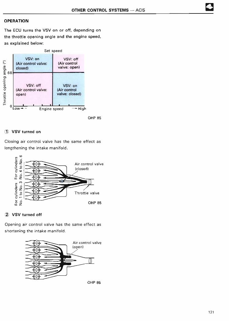
OTHER CONTROL SYSTEMS - ACI S
OPERATIO N
The ECU turns the VSV on or off, depending on
the throttle opening angle and the engine speed,
as explained below :
Set spee d
VSV: on
(Air control valve:
closed )
VSV: off(Air control valve:open)
Low-
VSV: off
(Air contro lvalve : open )
VSV: on(Air contro lvalve: closed )
Engine speed - High
OHP 85
1! VSV turned on
Closing air control valve has the same effect as
lengthening the intake manifold .
OHP 85
2, VSV turned off
Opening air control valve has the same effect as
shortening the intake manifold .
(open )Air control valv e
OHP 85
121

2 . TYPE 2
GENERAL
OTHER CONTROL SYSTEMS - ACI S
In this type of ACIS, the air control valves are
located in front of the No. 2 air intake chamber .
By opening and closing these valves i n
No. 2 ai r
intake chamber
OHP 86
(Po
OHP 87
Cross section A-A'
No. 1 air intake chamber
Air control valves
Vacuum tan k
P
Fro mair [-->cleaner
Intakemanifold
accordance with engine running conditions, the
same effect as lengthening or shortening the
intake manifold (as in Type 1) can be obtained.
Aircontrolvalve s
Combustionchamber
Vs V
Actuator Engine
ECU
Engine spee d
OHP 86
122

OTHER CONTROL SYSTEMS - ACI S
OPERATION
1 Low and medium speeds (below set speed)
The ECU turns the VSV on when the engine is
running at low to medium speeds . Therefore, the
vacuum (supplied by the vacuum tank) causes
the actuator to close the air control valves fully .
By closing the air control valves, the same effect
as lengthening the intake manifold is obtained .
This improves intake efficiency in the low- and
medium-speed ranges .
Throttle valve Air control
No. 1 air intake valve (closed)chamber
1-Z No. 2 ai ra~intak e
chamber
OHP 87
2 High speed (above set speed)
When the engine speed rises above the
predetermined speed, the ECU turns the VSV off
and the atmospheric air acts directly upon the
actuator. Therefore, the spring damper causes
the actuator to open the air control valves fully .
By opening the air control valves, the same
effect as shortening the intake manifold is
obtained. This shifts the peak intake efficiency
to the high engine speed range, improving
output in the high-speed range .
OHP 87 1 23
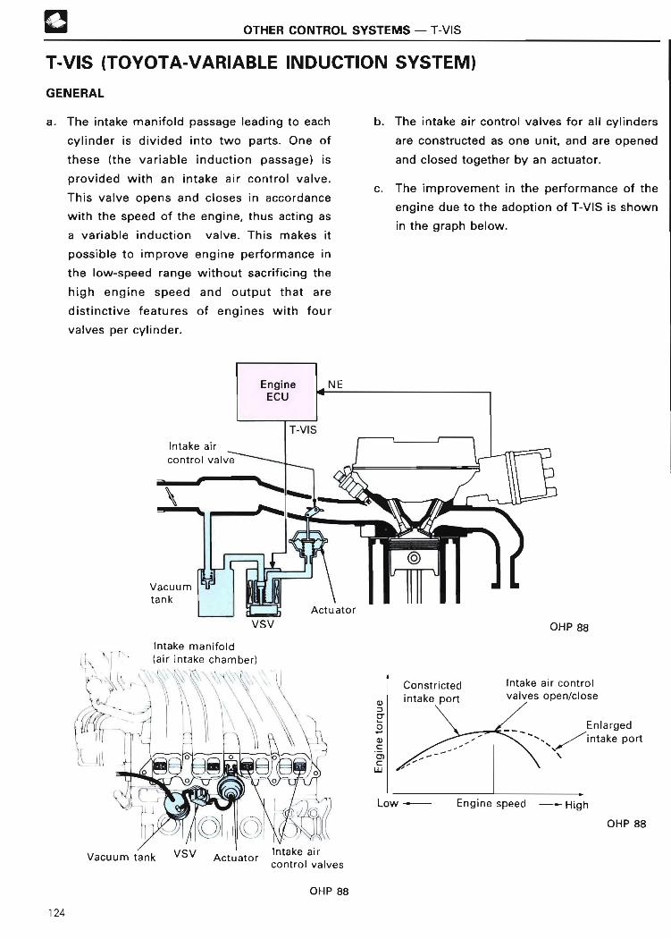
OTHER CONTROL SYSTEMS - T-VI S
T-VIS (TOYOTA-VARIABLE INDUCTION SYSTEM )
GENERAL
a . The intake manifold passage leading to each
cylinder is divided into two parts. One of
these (the variable induction passage) is
provided with an intake air control valve .
This valve opens and closes in accordance
with the speed of the engine, thus acting as
a variable induction valve . This makes it
possible to improve engine performance in
the low-speed range without sacrificing the
high engine speed and output that are
distinctive features of engines with four
valves per cylinder .
VSV
Intake manifold
(air intake chamber)
T-VIS
b. The intake air control valves for all cylinders
are constructed as one unit, and are opened
and closed together by an actuator .
c . The improvement in the pe rformance of the
engine due to the adoption of T-VIS is shown
in the graph below .
OHP 88
Low Engine speed --- High
OHP 88
OHP 88
EngineEC U
124

OTHER CONTROL SYSTEMS - Turbocharging Pressure Control Syste m
TURBOCHARGING PRESSURE CONTROL SYSTEM
The Engine ECU turns the VSV on and off* to This maximizes engine performance and
control the turbocharging pressure in accordance maintains engine durability, as well as
with the type of gasoline being used (regular or suppressing knocking under all engine running
premium), the coolant temperature, intake air conditions, including warm-up, irrespective of
temperature, intake air volume, and engine the gasoline octane rating .
speed . The VSV is controlled with the duty ratio in
some models .
Turbocharge r
OPERATION
The VSV is turned on by the ECU to increase the The VSV does not turn on unless all of the abov e
turbocharging pressure when the fuel is judged
to be premium by the fuel octane judgment
function (See page 116), and when the coolant
temperature and intake air temperature are
within a predetermined temperature, and the
intake air volume is above a predetermined
level .
conditions are met, even when premium
gasoline is used .
REFERENCE
For a detailed explanation of the construction
and operation of the turbocharger, see Step 3,
l .. 2 (Turbocharger and Supercharger) .vo
127

OTHER CONTROL SYSTEMS - Supercharger Control System, EHPS Control Syste m
SUPERCHARGER CONTROLSYSTEM
The Engine ECU controls the supercharger relay,
thus turning the supercharger magnetic clutch on
and off. It also controls supercharger operation
by controlling the supercharger bypass valve
(stepper motor type) .
In addition, the ECU controls the ACV to reduce
supercharger oil consumption .
Suspercharger bypas svalve (stepper motor type)
Engine EC U
AB,, A8 z
+B AC V(Air controlvalvel
Intercooler AB3, AB4Supercharge r
magnetic clutc hrela y
Supercharge r
+ B
Supercharger magneticclutch ACV
D
0
REFERRENCE
In previous models, VSV and ABV (air bypass
valve) have been used instead of a super-
charger bypass valve .
For a deteiled explanation of the construction
and operation of the supercharger, see Step 3,
vol . 2 (Turbocharger and Supercharger) .
SMC
Drive pully
EHPS (ELECTRO-HYDRAULICPOWER STEERING) CONTROLSYSTEM
In vehicles equipped with the EHPS, when the
engine coolant temperature or the engine speed
is very low, the load on the alternator is
increased when the vane pump motor of the
EHPS is driven . This condition makes it easier for
poor engine startability or engine stalling to
occur. To prevent this, the vane pump motor is
stopped during cold starting or when the engine
speed is extremely low .
PS ECU Engine EC U
OHP 90
REFERENCE
EHPS is a type of power steering in which the
vane pump is driven by an electric motor .
128

OTHER CONTROL SYSTEMS - AS Control System, Al Control Syste m
AS (AIR SUCTION) CONTROLSYSTE M
The AS system is operated by the ECU when
exhaust emissions tend to increase ; e.g., when
the engine is cold and during deceleration .
Under other operating conditions, this system
does not operate to prevent overheating of the
TWC (three-way catalyst) .
4
Al (AIR INJECTION) CONTROLSYSTE M
The Al system is operated by the ECU when
exhaust emissions tend to increase ; e .g ., when
the engine is cold and during deceleration .
Under other conditions, this system does not
operate to prevent overheating of the TWC .
OPERATION *
OPERATION *
The ECU switches on the VSV for the AS system
and operates the AS system when all of the
following conditions are met :
a . Engine col d
• Coolant temperature below 35°C (95°F)
• ER power enrichment not operating .
• Engine speed below a predetermined level .
b . Deceleratio n
• Coolant temperature above 35°C (95°F )
• IDL contact closed (accelerator pedal com-
pletely released . )
• Engine speed between about 1000 and 3000
rpm .
* Depending on the engine models .
VSV
Reed valver
VSV
OHP 9 1
From air cleaner
AS valve
When it is activated by the ECU, the VSV
introduces intake manifold vacuum into the ASV
(air switching valve) diaphragm chamber .
This causes the air discharged by the air pump to
pass through the check valve and be injected
into the cylinder head's exhaust port. If the
supply of current to the VSV is stopped,
atmospheric air is introduced into the ASV's
diaphragm chamber and the passage to the air
injection exhaust port is closed off, resulting in
the discharged air pushing against the spring
inside the ASV and being discharged outside
through the silencer .
* Depending on the engine models .
From air cleaner
129

11 OTHER CONTROL SYSTEMS - Al Control System
REFERENCE
There are some recent models in which the
Engine ECU sends the vehicle speed signal or
engine speed signal to combination meter . The
combination meter then operates the
speedometer and tachometer based on these
signals .
130

DIAGNOSIS - Genera l
DIAGNOSIS
GENERAL
The ECU contains a built-in diagnostic system .
Depending on the vehicle model, the diagnostic
system has a normal mode only, or it can have a
normal mode and a test mode .
In the normal mode, the ECU (which is
constantly monitoring most sensors) lights the
"CHECK ENGINE" lamp when it detects a
malfunction in certain sensors or their circuitry .
At the same time, the ECU registers the system
containing the malfunction in its memory . This
information is retained in memory even after the
ignition switch is turned off . When the vehicle is
brought into the shop because of trouble in the
engine control system, the contents of the
memory may be checked to identify the
malfunction .
"CHECK ENGINE"lamp
OHP 92
The "CHECK ENGINE" lamp does not light when
certain malfunctions are detected (See pages
138 to 140), because those malfunctions would
not cause any major trouble such as engine
stalling .
After a malfunction is corrected, the "CHECK
ENGINE" lamp turns off . However, the ECU
memory retains a record of the system in which
the malfunction occurred .
®
In most engines, the contents of the diagnostic
memory can be checked by connecting terminal
T or TE1 with El of the check connector or TDCL
(Toyota diagnostic communication link) and
counting the number of times the "CHECK
ENGINE" lamp blinks .
OHP 92
,- -rvv 1 rIn the case of OBD-II used for vehicles sold in
the U .S .A. and Canada, an OBD-II scan tool or
TOYOTA hand-held tester is required to read
diagnostic codes (See page 137-2) .
In some older model engines, the contents of the
diagnostic memory can be checked by
connecting a service wire to terminals T and El
of the check connector and an analog voltmeter
to terminals VF and El of the EFI service
connector, then checking the voltage
fluctuations .
In recent models, a test mode function has been
added to the functions of the diagnostic system
for the purpose of detecting intermittent problems
(such as poor contact) which are difficult to
detect in the normal mode .
CHECK7ENGIN E~
131
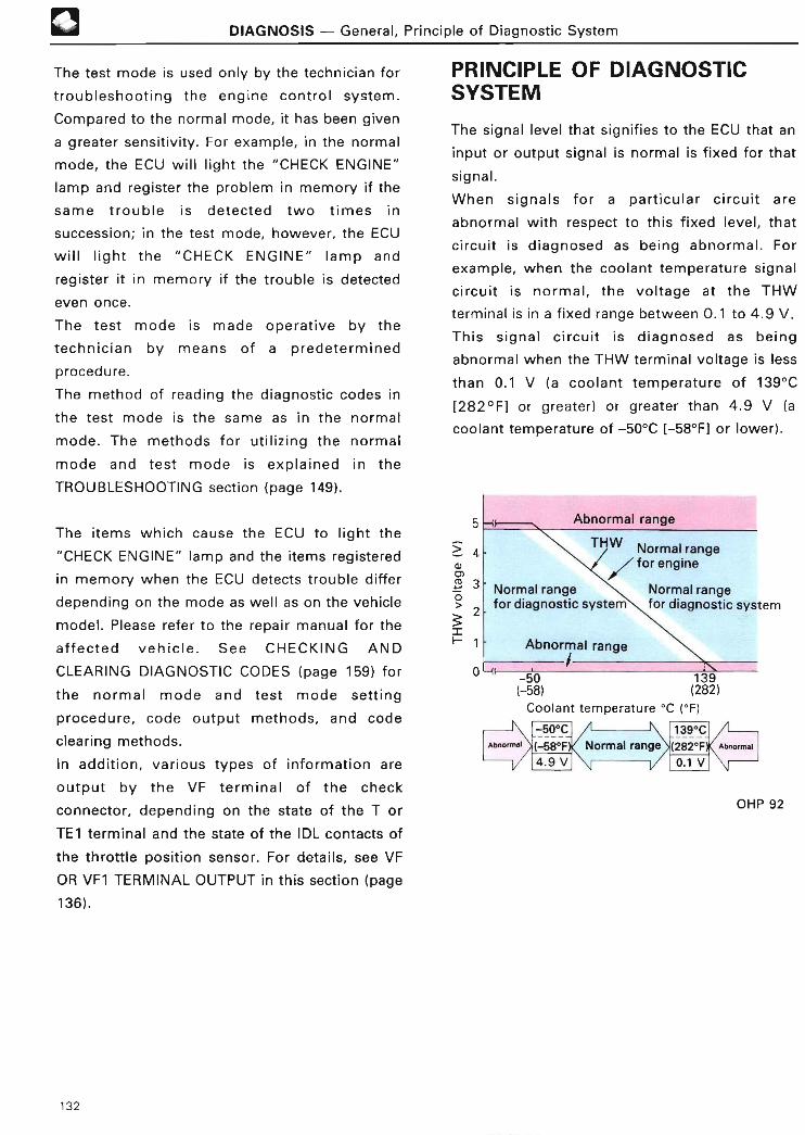
0 DIAGNOSIS - General, Principle of Diagnostic Syste m
The test mode is used only by the technician for
troubleshooting the engine control system .
Compared to the normal mode, it has been given
a greater sensitivity . For example, in the normal
mode, the ECU will light the "CHECK ENGINE"
lamp and register the problem in memory if the
same trouble is detected two times in
succession ; in the test mode, however, the ECU
will light the "CHECK ENGINE" lamp and
register it in memory if the trouble is detected
even once.
The test mode is made operative by the
technician by means of a predetermined
procedure .
The method of reading the diagnostic codes in
the test mode is the same as in the normal
mode. The methods for utilizing the normal
mode and test mode is explained in the
TROUBLESHOOTING section (page 149) .
The items which cause the ECU to light the
"CHECK ENGINE" lamp and the items registered
in memory when the ECU detects trouble differ
depending on the mode as well as on the vehicle
model . Please refer to the repair manual for the
affected vehicle . See CHECKING AND
CLEARING DIAGNOSTIC CODES (page 159) for
the normal mode and test mode setting
procedure, code output methods, and code
clearing methods .
In addition, various types of information are
output by the VF terminal of the check
connector, depending on the state of the T or
TE1 terminal and the state of the IDL contacts of
the throttle position sensor . For details, see VF
OR VF1 TERMINAL OUTPUT in this section (page
136) .
PRINCIPLE OF DIAGNOSTICSYSTEM
The signal level that signifies to the ECU that an
input or output signal is normal is fixed for that
signal .
When signals for a particular circuit are
abnormal with respect to this fixed level, that
circuit is diagnosed as being abnormal . For
example, when the coolant temperature signal
circuit is normal, the voltage at the THW
terminal is in a fixed range between 0 .1 to 4 .9 V .
This signal circuit is diagnosed as being
abnormal when the THW terminal voltage is less
than 0.1 V (a coolant temperature of 139°C
[282°F] or greater) or greater than 4 .9 V (a
coolant temperature of -50°C [-58°F] or lower) .
5 ~+r Abnormal rang e
4 THW Normal range/ for engin e
Normal range /( Normal rang efor diagnostic system for diagnostic syste m
3
2
1
0' -~ ~
Abnormal rangei
-50 139(-58) (282 )
Coolant temperature °C (°F )
-50°C~ / r ~
~(-58°F~/ Normal range
139°C
(282°F Abnormal
4.9 V
OHP 92
132

DIAGNOSIS - "CHECK ENGINE" Lamp and VF or VF1 Terminal Outpu t
"CHECK ENGINE" LAMP AND VF OR VF1 TERMINAL OUTPU T
The "CHECK ENGINE" ►amp and the output
voltage of the VF or VF1 terminal have the
following functions which differ depending on
the state of the T, TE1 or TE2*5 terminal (of-the
check connector or TDCL) and the idle contact in
the throttle position sensor .
TorTE1 TE2+5 IDL "CHECK ENGINE" LAMP VF or VF1 TERMINAL OUTPU TTERMINAL TERMINAL CONTACT
5 VIncreased injectio nvolum e
3 .75 VIncreased injectio n
Off volum e
Norma l• Bulb check function 5 V2 ---------------------- -------- -
(en ne stopped )9i Results of air-fuel . Air-fuel ratio feedbac kOff
• Warning display function ratio learned control 1 correction stopped * z(open)
with normal mode sed injectio nOff (engine operating) 1 .25 V
Dolum e(open)
Decreased injectio nOn volum e
0 V --- ------ - - --- -- - ------- -Air-fuel ratio feedbac kcorrection stopped + 2
On Off• Bulb check function
( TE2 and El ( engine stopped )di l f ii• W i ECU dEsp unct o narn ng ay ng ne at a
terminalsO test modewit h
connected) n( engine operating)
Results of oxygen sen- 5 V Rich signa l
i l isor s gna process ng
0 VLean signal or openloo p
operation * 4
Diagnostic code display function ---------------------------- ------- --- ---------------------------------- -Off with normal mode *' 5V Feedback correction no t
OffResults of lean mix- o r
5 V2taking plac e
On ture sensor signal pro- .(open )
IT or TE1 cessing
0 VFeedback correctio n
and E1 taking plac e
terminal s
connected) 5 V Norma l
l f di iOn Resu ts o agnost c
0 V Malfunction code store d
On Off(TE2 and E1 Diagnostic code display function ECU dE i at ang n eterminals
connected)On
with test mod e
*t Some systems have five levels, as shown here, while other systems have only three levels (0 V, 2 .5 V and 5 V) .`2 The VF or VF1 terminal output when air-fuel ratio feedback correction is not being carried out is either 0 V or 2 .5 V,
depending on the vehicle .
*3 Some models do not display diagnostic codes when the idle contact are off .
*4 "Open-loop operation" refers to the state in which the oxygen sensor signal is not being used for control (See
page 75) .
50n1y models having a test mode .
133

DIAGNOSIS - "CHECK ENGINE" Lamp and VF or VF1 Terminal Outpu t
1 . "CHECK ENGINE" LAMP FUNCTION S
LAMP CHECK FUNCTION (T or TE1 terminal off )
The "CHECK ENGINE" lamp goes on when the
ignition switch is turned on to inform the driver
that it has not burnt out . It goes out again when
the engine speed reaches 500 rpm . (The engine
speed may differ in some engine models . )
Bulb burnout
~*c 500 rpm1 -
About
LcK About 200 rpm OHP 9 3
WARNING DISPLAY FUNCTION IT or TE1terminal off)
When trouble occurs and the ECU has detected its
occurrence in one of the input/output signal cir-
cuits connected to the ECU (that is, one of those
marked "ON" in the "CHECK ENGINE" LAMP col-
umn of the table on page 138), the "CHECK
ENGINE" lamp goes on to aleart the driver . The
lamp goes off when conditions are restored to nor-
mal. (This occurs only at an engine speed of 500
rpm or higher) .
DIAGNOSTIC CODE DISPLAY FUNCTION (T orTE1 terminal on )
If the T or TE1 terminal is connected to the El
terminal (after the ignition switch is turned on),
diagnostic codes are displayed in order from the
smallest to the largest code, with the number of
times the "CHECK ENGINE" lamp blinks
indicating the malfunction code number.
In some engines, a test mode has been provided
which makes the diagnostic system more
sensitive. This system is also provided with a
TE2 terminal in the TDCL or check connector .
See CHECKING AND CLEARING DIAGNOSTIC
CODES (page 159) for the normal mode and test
mode setting procedure and the code output
methods .
REFERENCE
Super Monitor Display
When the results of a diagnostic output from
the warning lamp terminal (terminal W) are
displayed on a super monitor, the diagnostic
code display will not appear on the monitor, if
the injection signal is input to the Super
Monitor ECU by the Engine ECU even once .
+ B Super MonitorEngine ECU ~z EC U
Switches
J
2-TRIP DETECTION LOGI C
Some diagnostic codes, such as codes 21 and 25
(See page 138), use "2-trip detection logic" .
With this logic, when a malfunction is first
detected, it is temporarily stored in ECU memory .
If the same malfuntion is detected again, this se-
cond detection causes the "CHECK ENGINE"
lamp to light up . (However, the ignition switch
must be turned off between the 1 st time and 2nd
time) .
1st malfunctiondetection(temporaril yrecorded )
IG SWon
2nd malfunctiondetection(warninglight lights up )
Drivingpattern
IG SW IG SW IG SWoff on off
OHP 9 3
In the test mode, the "CHECK ENGINE" lamp
lights up the 1st time a malfunction is detected .
134

DIAGNOSIS - "CHECK ENGINE" Lamp and VF or VF1 Terminal Outpu t
DIAGNOSTIC MODE AND "CHECK ENGINE"LAM P
The diagnostic mode (normal or test) and the See CHECKING AND CLEARING DIAGNOSTIC
output of the "CHECK ENGINE" lamp can be CODES (page 159) for the normal mode and test
selected by changing the connections of the T or mode setting procedure and the code output
TE1, TE2 and El terminals on the check methods .
connector or TDCL, as shown in the table below .
T OR TE1 AND El TE2 AND El DIAGNOSTIC"CHECK ENGINE" LAM P
TERMINALS TERMINALS MODE
Open Normal Warns driver of malfunctio nOpen
Connected Test Notifies technician of malfunctio n
Open NormalOutputs diagnostic results (nature of malfunction), b ynumber of times lamp blinks .
Connected
Connected TestOutputs diagnostic results (nature of malfunction), bynumber of times lamp blinks .
135

DIAGNOSIS - "CHECK ENGINE" Lamp and VF or VF1 Terminal Outpu t
2 . VF OR VF1 TERMINAL OUTPUT
OUTPUT OF AIR-FUEL RATIO FEEDBACKCORRECTION (T, TE1 or TE2 terminal off )
The air-fuel ratio feedback correction amount is
output in three or five levels from the VF or VF1
terminal of the check connector. When the value
is normal, the output is constant at 2 .5 V, but
when the output is greater than 2.5 V, it
indicates that feedback correction is on increase
side, while an output lower than 2 .5 V indicates
that feedback correction is on decrease side .
Increasing 5 .0 V
3 .75 V
2.5 V
1 .25 V
Decreasing 0V
OHP 9 3
On engines which include a vane type air flow
meter, when the VF voltage is other than 2 .5 V,
this voltage can be adjusted by tightening the
idle mixture adjusting screw on the air flow
m ete r .
The VF or VF1 terminal output when air-fuel
ratio feedback correction is not being performed
is either 0 V or 2.5 V, depending on the vehicle
model .
Some vehicle models also have a VF2 terminal .
In V-type engines with a VF2 terminal, the VF1
terminal outputs information on the left bank
cylinders and the VF2 terminal outputs
information on the right bank cylinders .
In in-line 6-cylinder engines with a VF2 terminal,
the VF1 terminal outputs information on the No.
1 to No. 3 cylinders, and the VF2 terminal
outputs information on the No . 4 to No. 6
cylinders .
TE1 . When adjusting the idle mixture adjusting
screw, turn it slowly, a little at a time . If
this screw is turned too quickly, air-fuel
ratio feedback correction will be halted
and you will not be able to adjust the VF
voltage .
2. In vehicles in which the idle mixture
adjusting screw is sealed, the ECU
automatically adjusts the idle mixture .
Therefore, it is not necessary to adjust
the idle mixture .
-REFERENCE
VF or VF1 Terminal Voltag e
When measured on an oscilloscope, the
output waveform of the VF or VF1 terminal
voltage has a constant period of
approximately 32 msec (depending on the
engine model), as shown in the figure below .
4 V
2 V
0V
20 msec.
I I I __1
+---i
32 msec.
When a voltmeter is used to measure the
value, a virtually constant value is displayed .
136

DIAGNOSIS - "CHECK ENGINE" Lamp and VF or VF1 Terminal Outpu t
OXYGEN SENSOR SIGNAL OUTPUT IT or TE1terminal on, TE2 terminal off, idle contact off )
To read the output of the oxygen sensor,
connect terminal T or TE1 with terminal El, with
the idle contact off . Then measure the voltage at
the VF or VF1 terminal . (The output from this
terminal is not the actual signal that is output by
the oxygen sensor, but a signal that has been
digitalized by the ECU for easier reading . )
This signal is 5 V when the input signal from the
oxygen sensor is higher than the comparison
voltage set by the ECU, and is 0 V when the
input signal is lower than the comparison
voltage or during an open-loop operation .
Comparisonvoltage
0V(lean )
VF or VF1terminalvoltage
OHP 93
When using a voltmeter to check air-fuel ratio
feedback correction, first warm up the oxygen
sensor by warming up the engine, then, while
maintaining engine speed at 2,500 rpm to keep
the idle contact off, measure the VF voltage .
(See page 182 for the method of outputting this
signal . )
LEAN MIXTURE SENSOR SIGNAL OUTPUT(T or TE1 terminal on, TE2 terminal off, idlecontact off )
This signal is 0 V while air-fuel ratio feedback
correction is taking place, and 2 .5 V or 5 V when
air-fuel ratio feedback correction is not taking
place . (See page 183 for the method of
outputting this signal .)
DIAGNOSIS OUTPUT (T or TE1 terminal on, TE2terminal off, idle contact on )
J Output of result s
Connecting the T or TE1 terminal to the El
terminal causes the ECU (VF or VF1 terminal) to
signal whether there are any data in the
diagnostic memory or not . If all the diagnostic
results are normal, a 5 V signal will be output,
but if any malfunction codes are stored in
memory, a 0 V signal will be output (that is, the
voltage at the VF or VF1 terminal will fall to
zero) .
~2 Diagnostic code number outpu t
In older model engines, diagnostic results are
read by connecting an analog voltmeter to the
VF terminal and counting the number of
oscillations of the needle of the voltmeter . This
number corresponds to the trouble code number,
which can then be looked up to identify the
trouble .
See the relevant repair manual concerning the
output method for the diagnostic codes and
display format .
137

141 DIAGNOSIS - "CHECK ENGINE" Lamp and VF or VF1 Terminal Outpu t
ENGINE ECU DATA OUTPUT (TE2 terminal on )
In engines having a test mode for diagnosis, the
Engine ECU has the function to output data
calculated according to signals from each sensor .
Output data accounts for a portion of input data
from sensors and output data to actuators . Since
the data is output in the form of serial communica-
tions, it cannot be read without using a TOYOTA
hand-held tester, DIAGNOSIS READER or
DIAGNOSIS MONITOR .
Refer to the Repair Manual or the Handling
Manual of a TOYOTA hand-held tester,
DIAGNOSIS READER or DIAGNOSIS MONITOR
for information on the reading procedure and out-
put parameters .
~ REFERENCE
I Serial Communication :
Serial communication is one of digital com-
munication . One piece of data is sent by com-
bining high (1) and low (0) signals for each unit
time (t) .
Multiple pieces of data can be sent with a
single communication line .
Hig h
Low J
t' t2 t3 /
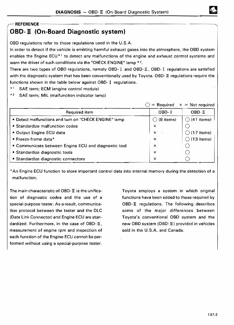
DIAGNOSIS - OBD-I[ (On-Board Diagnostic System )
FOREFERENCE
BD- If (On-Board Diagnostic system )
OBD regulations refer to those regulations used in the U .S .A.
In order to detect if the vehicle is emitting harmful exhaust gases into the atmosphere, the OBD system
enables the Engine ECU *' to detect any malfunctions of the engine and exhaust control systems and
warn the driver of such conditions via the "CHECK ENGINE" lamp * z .
There are two types of OBD regulations, namely OBD- I and OBD-I[ . OBD- I regulations are satisfied
with the diagnostic system that has been conventionally used by Toyota. OBD-II regulations require the
functions shown in the table below against OBD- I regulations .
* i
*zSAE term ; ECM (engine control module)
SAE term ; MIL (malfunction indicator lamp)
0= Required . x = Not required
Required item OBD- I OBD-II
• Detect malfunctions and turn on "CHECK ENGINE" lamp 0 (8 items) 0 (41 items)
• Standardize malfunction codes x 0• Output Engine ECU data x 0 (17 items)
• Freeze-frame data* x 0 (13 items )
• Communicate between Engine ECU and diagnostic tool x 0• Standardize diagnostic tools x 0• Standardize diagnostic connectors x 0
*An Engine ECU function to store important control data into internal memory during the detection of a
malfunction .
The main characteristic of OBD-II is the unifica-
tion of diagnostic codes and the use of a
special-purpose tester . As a result, communica-
tion protocol between the tester and the DLC
(Date Link Connector) and Engine ECU are stan-
dardized . Furthermore, in the case of OBD-II,
measurement of engine rpm and inspection of
each function of the Engine ECU cannot be per-
formed without using a special-purpose tester .
Toyota employs a system in which original
functions have been added to those required by
OBD-II regulations. The following describes
some of the major differences between
Toyota's conventional OBD system and the
new OBD system (OBD-II) provided in vehicles
sold in the U .S.A. and Canada .

4 DIAGNOSIS - OBD-II (On-Board Diagnostic System )
Conventional OBD New OBD (OBD-II )
CHECK ENGINE When a proble mLAMP has been detected Lights Lights or blinks
When the proble mhas been solved Goes off after about 5 seconds Goes off after 2 or 3 trip s
DIAGNOSTIC Code 2 digits ( e .g . : 25, 31) 5 digits (e .g . : P0120 )CODE
Reading operation Connection of terminal TE 1and terminal E l
Code display "CHECK ENGINE" lamp blink s
Code clearing*' Removal of memory fuseOBD-II scan tool o rTOYOTA hand-held teste r
ENGINE ECU Reading operation Connection of terminal TE 2DATA and terminal E l
Reading DIAGNOSIS REDER, DIAGNOSI S
instruments MONITOR, or TOYOTA hand-hel dteste r
Output terminal Terminal VF Terminal SDL* 2
CommunicationSlow (about 1 .5 seconds) Fast ( about 0 .05 to 1 .0 seconds )rate
Data display Few Man yitems
Data displaymethod Toyota standard SAE standard
ACTIVE TEST*3 Not available Available ( performed using a nOBD-II scan tool or TOYOT A
FREEZE-FRAM DATA Not available hand-held tester )
* i
+ z
•3
In the case of a new OBD (OBD-II), diagnostic codes can also be cleared by removing the memory fuse in thesame manner as the conventional OBD .SDL; The communication terminal between the Engine ECU and the TOYOTA hand-held tester use the VPW
(Variable Pulse Width) system in accordance with the SAE J1850 requirements .Actuators (injector, ISC valve, etc .) are operated by sending a signal from the tester to the Engine ECU .

DIAGNOSIS - OBD-I[ (On-Board Diagnostic System )
Conventional OBD New OBD (OBD-I[ )
CHECKCHECK W E1 OX1 CC2 IG- TE1 E l
CONNECTORCONNECTOR TEl
O(DLC) AND
(DLC 1 )TER MINAL
tM
FP D(Only those CC
related to the +B lJ CDEngine ECU)
VF1 VF2TE2OX2 TT + B
TDCLECT W
(DLC2)
EN G
TT
E1 TE2 TE1 E l
DLC3BATT SDL* '
?CG*3
SDL; The communication terminal between the Engine ECU and the TOYOTA hand-held tester use the VPW
(Variable Pulse Width) system in accordance with the SAE J1850 requirements .
*zSG ; Signal graund*3CG ; Chassis graund

DIAGNOSIS - Diagnostic Code s
DIAGNOSTIC CODE SThe "CHECK ENGINE" lamp lights up when trou-
ble occurs. It goes off again 5 seconds after the
relevant system is restored to normal .
(Remember, however, that when the engine
speed is lower than 500 rpm, the lamp may light
up for the bulb burnout check . )
If two or more problems have occurred and are
stored in memory, the malfunction codes will be
displayed in order from the smallest code.
Code numbers and their meanings for the 4A-
FE engine (Corolla AE101 for Europe) are as
shown in the following table .
Diagnostic items and the meanings of the
malfunction codes differ depending on the
engine model . For details, see the Repair
Manual for the relevant engine .
(As Feb ., 1992 )
C E NGINE ""C HCODE
NUMBER OF TIME S"CHECK ENGINE" LAMP CIRCUITRY
LA~ P
DIAGNOSIS 2
NO . BLINKS NORMAL TEST (MEANING OF TROUBLE CODE) TROUBLE AREA MEMOR Y
MODE MODE
- J Ll LI LI LI LJ LI LI L Normal - - Output when no other code is recorded . - -
• No "NE" signal to ECU within 2 seconds• Open or short in NE, G
after engine is cranked .circuit
12 RPM signal ON N .A . • No "G" signal to ECU for 3 seconds when• IIA 0
the engine speed is between 600 rpm and• Open or short in STA
4000 rpm . circuit• ECU
ON N .A .No "NE" signal to ECU when the engin espeed is above 1 500 rpm .
• Open or short in NE circui t13
n n n n RPM signal No "G" signal to ECU while "NE" signal is • IIA 0N .A . ON input 4 times to ECU when engine speed is • EC U
between 500 rpm and 4000 rpm .
• Open or short in IGF or IG T
14 n UJ jL_ Ignition signal ON N .A . No " IGF" signal to ECU 4 times in succession . circuit from igniter to ECU O• Ignite r
• ECU
• Open or sho rt in heate r
N .A . Open or short circuit in oxygen sensor heater circuit of oxygen senso rwire (HT) . • Oxygen sensor heater
rI Oxygen • ECU
21 n n sensor OFF During air-fuel ratio feedback correction, Ocircuit output voltage of oxygen sensor remains
• Open or short in oxyge n
ON between 0 .35 V and 0 .7 V continuously for asensor circuit
ce rt ain period . • Oxygen senso r
" (2 trip detection logic) • EC U
• Open or short in wate r
22 n n n n Water temp .ON ON
Open or sho rt circuit in water temp . sensor temp . sensor circuitsensor signal signallTHWI . • Water temp . sensor 0
• ECU
Intake air• Open or short in intake ai r
24 temp . sensor OFF ONOpen or sho rt circuit in intake air temp . sensor temp . circuit 0
signalsignal ( THA) . • Intake air temp . senso r
• ECU
• Engine ground bolt loose
• Open in E1 circui t
Oxygen sensor output is less than 0 .45 V for• Open in injector circuit
25 J U LJ I.J IJ U LJ LAir-fue lratio lean OFF ON at least 90 secs . or more when oxygen sensor
• Fuel line pressure
(Injector blockage, etc .) 0malfunction is warmed up (racing at 2,000 rpm) .3*3 (2 trip detection logic) • Open or short in oxyge n
sensor circuit• Oxygen senso r
• Ignition syste m
Vacuum• Open or short in vacuu m
31 n n n n sensor ON ON Open or short circuit in manifold pressure sen- sensor circuitO
signalsor signal (PIM) . • Vacuum senso r
• EC U
138

DIAGNOSIS - Diagnostic Code s
"CHECK ENGINE" , z
CODENUMBER OF TIME S_ " UITRY
LAMP" DIAGNOSIS TROUBLE AREA MEMORYNO . CHECK ENGINE LAMP CIRC
NORMAL TEST (MEANING OF TROUBLE CODE )BLINKS
MODE MODE
Throttle • Open or short in throttl enn r
Jnn ULI LI LJ L position OFF ONOpen or short circuit in throttle position position sensor circuit 041 --
sensor sensor signal (VTA ) . • Throttle position senso r
signal • EC U
OFF N A No "SPD" signal to ECU for 8 seconds whe n. .
vehicle is running . • Open or short in vehiclerI rI fl rl r1 f1 Vehicle speed speed sensor circuit Q, •
42 J ll lJ ll LJ U L- sensor signal • Vehicle speed senso r
N A OFFNo "SPD" signal input to ECU after ignition • EC U. .switch is turned on .
• Open or short in starte r
43nn~7n nn n
J LI LI u L~ u U L Starter signal N .A . OFFNo "STA" signal input to ECU after ignition
signal circui t• Open or short in IG SW or x
switch is turned on .main relay circui t
• ECU
• Open or sho rt in knoc kWith engine speed between 1,200 rpm and sensor circui t
52 ~Knock sensor
ON N .A . 6,000 rpm, signal from knock sensor is not • Knock sensor (looseness, 0signal input to ECU for certain period . ( KNK) etc . )
• ECU
Displayed when A/C is ON, IDL contact OFF or~ A/C switch syste m
Switch"R", "D", "2", or "L" rang eshift lever is in
Throttle position senso r
51's ~_ condition N .A . OFFand STA is OFF with the check terminals El IDL circuit x
signals and TE1 connected at test mode . • Accelerator pedal, cabl e
• ECU
+ 1
* 2
* 3
*4
5
"ON" displayed in the diagnosis mode column indicates that the "CHECK ENGINE" lamp is lighted up
when a malfunction is detected . "OFF" indicates that the "CHECK ENGINE" lamp does not light up dur-
ing malfunction diagnosis, even if a malfunction is detected . "N .A ." indicates that the item is not includ-
ed in malfunction diagnosis .
Lighting of the "CHECK ENGINE" lamp varies depending on engine models and the destinations .
" 0" in the memory column indicates that a diagnostic code is recorded in the ECU memory when a
malfunction is detected . " x" indicates that a diagnostic code is not recorded in the ECU memory even
if a malfunction is detected . Accordingly, output of diagnostic results in normal or test mode is perform-
ed with the ignition switch ON .
"2 trip detection logic" (See page 134) is only active at the normal mode .
Not stored in memory at the test mode .
IDL contact off is not detected until after the engine starts .
139

DIAGNOSIS - Diagnostic Codes
ncrcnicrv%,c
Examples of diagnostic codes of OBD-II com- OBD-II system has a check mode function in
patible engines in vehicles sold in the U .S.A . which detection of a problem has greater sen-
and Canada are show below . In the same sitivity than the normal mode .manner as the conventional OBD system, th e
• Camry 1 MZ-FE engine (1994 model year )
COD ENO CIRCUITRY
"CHECKENGINE"
DIAGNOSISTROUBLE AREA MEMOR Y.
LAMP • ~(MEANING OF TROBLE CODE )
P0100Mass air flow circuit ON Open or short in mass air flow meter circuit with • Open or short in mass air flow meter circuit
malfunction engine speed 4,000 rpm or less• Mass air flow meter 0• ECU
Conditions a) and b) continue with engine spee dMass air flow circuit 900 rpm or less :
P0101 range/performance ON (2 trip detection logic) `3 • Mass air flow meter 0problem a) Closed throttle position switch : ON
b) Mass air flow meter output > 2 .2 V
• Open or short in intake air temp . senso r
P0110Intake air temp . circuit
lf i ON Open or short in intake air temp . sensor circuitcircuit O
ma unct on • Intake air temp . senso r• ECU
• Open or short in engine coolant temp .
P0115Engine coolant temp . ON Open or short in engine coolant temp . sensor sensor circuitcircuit malfunction circuit • Engine coolant temp . sensor
O
• ECU
Engine coolant temp . 20 min . or more after starting engine, engin e
P0116 circuitrange/ ONcoolant temp . sensor value is 30°C (86°F) of • Engine coolant temp . sensor 0
performance problemless • Coolant syste m(2 trip detection logic)' 3
+ 1
* 2
*3
"ON" displayed in the diagnosis mode column indicates that the "CHECK ENGINE" warning light is
lighted up when a malfunction is detected .
"0" in the memory column indicates that a diagnostic code is recorded in the ECU memory when a
malfunction is detected . Accordingly, output of diagnostic results in normal or test mode is perform-
ed with the ignition switch ON .
" 2 trip detection logic" (See page 134) .
140
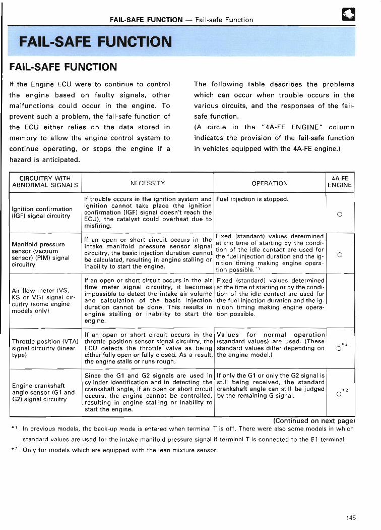
FAIL-SAFE FUNCTION - Fail-safe Function
FAIL-SAFE FUNCTIO N
FAIL-SAFE FUNCTIO N
If the Engine ECU were to continue to control
the engine based on faulty signals, other
malfunctions could occur in the engine . To
prevent such a problem, the fail-safe function of
the ECU either relies on the data stored in
memory to allow the engine control system to
continue operating, or stops the engine if a
hazard is anticipated .
®
The following table describes the problems
which can occur when trouble occurs in the
various circuits, and the responses of the fail-
safe function .
(A circle in the "4A-FE ENGINE" column
indicates the provision of the fail-safe function
in vehicles equipped with the 4A-FE engine . )
CIRCUITRY WITH 4A-F E
ABNORMAL SIGNALS NECESSITY OPERATION ENGIN E
If trouble occurs in the ignition system and Fuel injection is stopped .
Ignition confirmationignition cannot take place (the ignition
't reach th econfirmation [IGF] signal doesn 0(IGF) signal circuit ry ECU), the catalyst could overheat due t omisfiring .
If an open or sho rt circuit occurs in theFixed (standard) values determine dat the time of starting by the condi -Manifold pressure intake manifold pressure sensor signal tion of the idle contact are used fo rsensor (vacuum circuit ry , the basic injection duration cannot the fuel injection duration and the ig- 0
sensor) (PIM) signal be calculated, resulting in engine stalling or nition timing making engine opera-circuit ry inability to sta rt the engine .tion possible .
If an open or sho rt circuit occurs in the air Fixed (standard) values determine dflow meter signal circuitry, it becomes at the time of starting or by the condi -
Air flow meter (VS ,Air impossible to detect the intake air volume tion of the idle contact are used fo ror VG) signal cir- and calculation of the basic injection ig -the fuel injection duration and the ig -cuitry Isome engine duration cannot be done . This results in nition timing making engine opera -
models only )models stalling or inability to sta rt the tion possible .engine .
If an open or sho rt circuit occurs in the Values for normal operatio n
Thrott le position (VTA) thrott le position sensor signal circuit ry , the (standard values) are used . (These Z
signal circuit ry (linear ECU detects the throttle valve as being standard values differ depending on0
type) either fully open or fully closed . As a result, the engine model . )the engine stalls or runs rough .
Since the G1 and G2 signals are used in If only the G1 or only the G2 signal i s
cylinder identification and in detecting the still being received, the standar dEngine crankshaft crankshaft angle, if an open or sho rt circuit crankshaft angle can still be judge dangle sensor (G1 and occurs, the engine cannot be controlled, by the remaining G signal . 0G2) signal circuit ry resulting in engine stalling or inability to
sta rt the engine .
. 1
•2
(Continued on next page )In previous models, the back-up mode is entered when terminal T is off . There were also some models in which
standard values are used for the intake manifold pressure signal if terminal T is connected to the El terminal .
Only for models which are equipped with the lean mixture sensor .
145

0 FAIL SAFE FUNCTION - Fail-safe Function
CIRCUITRY WITH 4A-F EABNORMAL SIGNALS NECESSITY OPERATION ENGIN E
• Water temp .If an open or sho rt circuit occurs in the Values for normal operatio n
sensor (THW)water temperature or intake air (standard values) are used . These
signal circuit ry temperature signal circuitry the ECU standard values differ depending o nassumes that the temperature is below engine characteristics, but generally ,
• Intake air temp . -50°C (-58°F) or higher than 139°C (274°F) . a coolant temperature of 80°C 0sensor (THA) This results in the air-fuel ratio becoming (176°F) and an intake ai r
signal circuit ry too rich or too lean, which results in engine temperature of 20°C (68°F) are used .stalling or the engine running rough .
If the cover of the lean mixture sensor Air-fuel ratio feedback correction i sbecomes fouled with carbon, the ECU stopped .
Lean mixture sensor cannot detect the correct oxygen 0 .(LS) signal circuit ry concentration in the exhaust gas, so i t
cannot keep the air-fuel ratio at theoptimal level .
• Knock sensorIf an open or sho rt circuit occurs in the The corrective retard angle is set t o
(KNK) signalknock signal circuit ry , or if trouble occurs in the maximum value .
circuitrythe knock control system inside the ECU,whether knocking occurs or not, ignitio n
• Knock controltiming retard control will not be carried out
systemby the knock control system . This couldresult in damage to the engine .
If an open or sho rt circuit occurs in the HAC Values for normal operatio n
High-altitude sensor signal circuitry, the high-altitude (standard values) are used . The
compensatior sensorcompensation correction will be either the standard atmospheric pressur e
(HAC) signal circuit ry maximum or the minimum value . This will value is 101 kPa (60 mmHg, 29 . 9cause the engine to run poorly or reduce in.Hg) .drivability .
TurbochargingAbnormal increases in the turbocharging Fail-safe stops engine by stoppin g
pressure (PIM) signal pressure or intake air volume, as well as fuel injection.
circuit ry other factors, may cause damage to th eturbocharger or engine .
Transmission controlIf trouble occurs in the microprocessor for Torque control correction (See page
signal transmission control, the transmission will 96) by the ESA is stopped .not operate properly .
If the amount of coolant supplied to the The ignition timing is retarded by 2° .intercooler is insufficient, its coolin g
Intercooler ECU (WIN)capacity will drop. This will cause th e
signal circuit ry temperature of air taken into the cylindersto rise . As a result, the temperature of th egas inside the combustion chamber wil lrise even higher, making it easy fo rknocking to occur .
*Only for models which are equipped with the lean mixture sensor .
146

BACK-UP FUNCTION - Back-up function
BACK-UP FUNCTIO N
BACK-UP FUNCTIO N
The back-up function is a system which switches
to the back-up IC for fixed signal control* if
trouble occurs with the microprocessor inside
the ECU . This allows the vehicle to continue
operating, though it assures the continuation of
l
Engine ECU
Back-up I C
STA :::=IDL
Malfunctionmonitor
only basic functions ; normal performance cannot
be maintained .
*Control by the back-up IC in which the IC uses
preprogrammed data to control the ignition
timing and fuel injection duration .
Microprocesso r
*Injectionsignal
0-O
Varioussignal s
*Ignitio ntimingsignal
IGT Xnk 1 o,zo -&-
OPERATIO N
The ECU switches to the back-up mode when the
microprocessor stops outputting the ignition tim-
ing (IGT) signal .
When the ECU switches to the back-up mode, fix-
ed values* are substituted for fuel injection dura-
tion and ignition timing and as a result, engine
operation is maintained . The back-up IC sets the
fixed values* according to the condition of the
STA signal and the idle contact . At the same time,
it lights the "CHECK ENGINE" lamp to inform the
driver .
(Codes are not output in this case, however . )
*These values differ depending on the engine
model .
In addition, on some recent models, when the
back-up mode is entered, the engine is stopped by
interrupting fuel injection .
/__ NOT E
In the case of conventional D-type EFI, when
the intake manifold pressure (PIM) signal was
open or short circuited, the microprocessor for-
cibly switched to the back-up mode by interrup-
ting the ignition timing (IGT) signal . More
recently, however, fixed values for fuel injec-
tion duration and ignition timing are contained
within the microprocessor . As a result, when a
problem like that described above occurs, the
microprocessor controls the engine with a fail
safe function .
147

8b l
OW3W
TROUBLESHOOTING - General
TROUBLESHOOTING
GENERAL
The TCCS engine control system is a very
complicated system requiring a high level of
technical knowledge and expertise to
troubleshoot successfully .
However, the basics of troubleshooting are the
same whether an engine is equipped with a
TCCS engine control system or it is a carbureted
engine. In particular, you must look for:
• An appropriate air-fuel mixture• A high compression pressure• Correct ignition timing and powerful sparks
Making effective use of the diagnostic system
( See page 131) and taking into careful
consideration the three items mentioned above
will eliminate the complexities involved in
troubleshooting vehicles with TCCS .
It is also ve ry important to follow the correct
procedures at all times . This section explains the
general procedures and concepts involved in
troubleshooting, from the point when the vehicle
is brought into the se rvice shop until the trouble
is found and repaired and the confirmation test
performed .
For correct troubleshooting procedures for a
particular engine, see the Repair Manual for that
engine model .
149
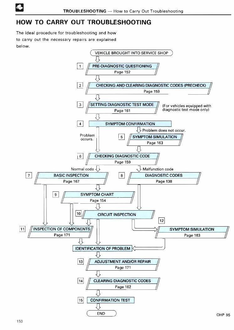
TROUBLESHOOTING - How to Carry Out Troubleshooting
HOW TO CARRY OUT TROUBLESHOOTIN G
The ideal procedure for troubleshooting and how
to carry out the necessary repairs are explained
below .
C VEHICLE BROUGHT INTO SERVICE SHO P
1 PRE-DIAGNOSTIC QUESTIONING
Page 15 2
2 CHECKING AND CLEARING DIAGNOSTIC CODES (PRECHECK)
Page 15 9
SETTING DIAGNOSTIC TEST MODE (For vehicles equipped with
Page 161 diagnostic test mode only )
4
Problemoccurs .
6
Problem does not occur .
SYMPTOM SIMULATIO N5
,aCHECKING DIAGNOSTIC CODE
Page 15 9
Normal code ~ Malfunction cod e
9
[L
~
7
INSPECTION OF COMPONENTS//Page 17 1
BASIC INSPECTION
Page 167
CIRCUIT INSPECTION
i3 DIAGNOSTIC CODES
Page 13 8
SYMPTOM CHART
Page 15 4
V
IDENTIFICATION OF PROBLEM
13
14
Page 163
71 2
~ SYMPTOM SIMULATION
Page 16 3
ADJUSTMENT AND/OR REPAIR
Page 17 1
,aCLEARING DIAGNOSTIC CODES
Page 16 2
`c~15 CONFIRMATION TEST
,aC END
SYMPTOM CONFIRMATION
OHP 95
150

TROUBLESHOOTING - How to Carry Out Troubleshooting
PRE-DIAGNOSTIC QUESTIONIN G
Refering to the Pre-diagnostic Questioning
Checksheet, ask the customer about the
problem in as much detail as possible .
CHECKING AND CLEARING DIAGNOSTIC
CODES (PRECHECK )
Before confirming the symptoms, check the
diagnostic code in the normal mode and
make a note of any malfunction codes dis-
played, then clear the codes .
3 SETTING DIAGNOSTIC TEST MOD E
(for vehicles equipped with diagnostic test
mode . )
In order to find the cause of the problem
more quickly, set the system in the
diagnostic test mode .
SYMPTOM CONFIRMATIO N
Confirm the symptoms of the problem .
SYMPTOM SIMULATION
If the symptoms do not reappear, use the
symptom simulation method to reproduce
them .
CHECKING DIAGNOSTIC COD E
Check the diagnostic codes. If the normal
code is output, proceed to step ❑~ . If a mal-
function code is output, proceed to ste p
BASIC INSPECTION
8
Carry out a basic inspection, such as an ig-
nition spark check, fuel pressure check, etc .
8 DIAGNOSTIC CODES
If a malfunction code was output in step 6check the trouble area indicated by the
diagnostic code chart .
1 1
1 2
1 3
15
SYMPTOM CHART
If a trouble was not confirmed in step ❑
perform troubleshooting according to the in-
spection items in the symptom chart .
CIRCUIT INSPECTIO N
Proceed with the diagnosis of each circuit
between the ECU and the component in
accordance with the inspection items
confirmed in step ® or step ❑ . Determine
whether the cause of the trouble is in the
sensors, the actuators, the wire harness or
connector, or the ECU.
INSPECTION OF COMPONENTS
Inspect the problematic components .
SYMPTOM SIMULATION
If the cause of the trouble is momentary
(intermittent) interruptions or shorts, pull
gently on the wire harness, connectors, and
terminals, and shake them gently to isolate
the place where the trouble is occurring due
to poor contact .
ADJUSTMENT AND/OR REPAI R
After the cause of the trouble is located, per-
form the necessary adjustment or repair .
CLEARING DIAGNOSTIC CODES
Clear the diagnostic codes .
CONFIRMATION TEST
After completing the adjustment or repairs,
check to see whether the trouble has been
eliminated, and perform a test drive to make
sure the entire engine control system is
operating normally and that the diagnostic
code displayed is the normal code .
151

TROUBLESHOOTING - Pre-diagnostic Questioning
PRE-DIAGNOSTIC QUESTIONING (PDQ)
When carrying out troubleshooting, it is impor- • Who noticed the problem ?
tant that the technician remember to confirm the - With whom the problem most commonly
symptoms of the problem accurately and objec- occur s
tively, without preconceptions . (This means, for• What?
example, not to just guess about the cause o f
the problem, no matter how much experience - Vehicle model
- System in which problem has occurredthe technician is basing his judgement on, but t o
carry out the troubleshooting step by step, ac- • When?
cording to the directions given here .) - Date(s)
No matter how experienced the technician, if -Time(s)
troubleshooting is attempted before the - Frequency of occurrence
symptoms have been confirmed, repairs will fai l
or a mistaken judgment will lead to the wrong• Where7
repairs being performed. - Type of road/terrain
As long as the symptoms of the problem are • How? Under what conditions?
manifesting themselves at the time the vehicle - Engine running conditions
is brought into the service shop, they can be - Driving conditions
confirmed right away. However, when the - Weathe r
symptoms fail to manifest themselves, the • Whydid customer bring vehicle in?
technician must deliberately try to reproduce- Symptoms
them. For example, a problem that occurs onl y
when the vehicle is cold or the occurrence of A sample of a PDQ Checksheet is shown on the
vibration from the road surface during driving following page .
cannot be confirmed when the engine is warmed
up or while the vehicle is sitting still, because
the conditions under which the trouble occurred
cannot be reproduced under such circumstances .
Therefore, when attempting to ascertain what
the symptoms are, it is extremely important to
ask the customer about the problem and the
conditions under which they occurred .
IMPORTANT POINTS IN PD Q
The six items shown below are especially impor-
tant points to remember when carrying out Pre-
diagnostic Questioning .
Information on past problems (even if they are
thought to be unrelated to the present problem)
and the repair history of the vehicle will also
help in many cases, so as much information as
possible should be gathered and its relationship
with the symptoms should be correctly
asce rtained for reference in troubleshooting .
152

TROUBLESHOOTING - Pre-diagnostic Questioning
PRE-DIAGNOSTIC QUESTIONING CHECKSHEETInspector's
Name :
Customer'sModel and model yea r
name
Driver's name Frame no .
Date vehicleEngine mode l
brought in
License no. Odometer readingkmmiles
❑ Engine does ❑ Engine does not crank ❑ No initial combustion ❑ Incomplete combustio nnot start
❑ Difficult to ❑ Engine cranks slowl ystart ❑ Other
E ❑ Poor idling ❑ No fast idle ❑ Idling speed : ❑ High ❑ Low ( rpm)❑ Rough idling ❑ Other
C LE ❑ Poor ❑ Hesitation ❑ Backfiring ❑ Afterfiring (muffler explosions) ❑ Surgin g
driveability ❑ Knocking ❑ Other
❑ Soon after sta rting ❑ After accelerator pedal is depresse d❑ Engine stalls ❑ After accelerator pedal is released ❑ During A/C operatio n
❑ Shifting from "N" to "D" ❑ Other
❑ Others
Datels) of problemoccurrence
Frequency of problem ❑ Constant ❑ Sometimes (times per day/month) ❑ Once onlyoccurrence ❑ Other
Weather ❑ Clear ❑ Cloudy ❑ Rainy ❑ Snowy ❑ Various/othe r
o m Outdoor ❑ Hot ❑ Warm ❑ Cool ❑ Cold (approx . _°C /_°F)~ temperatur eE
Place /road ❑ Highway ❑ Suburbs ❑ Inner city ❑ Uphill ❑ Downhil l
W ~ conditions ❑ Rough road ❑ OtherN VC
« E Engine temp . ❑ Cold ❑ Warming up ❑ Normal ❑ Othere
~ o ❑ Sta rting ❑ Just after sta rt ing ❑ Idling ❑ Racin gcg a Engine operation ❑ Driving ❑ Constant speed ❑ Acceleration ❑ Deceleration
❑ Other
Condition of "CHECK ENGINE" lamp ❑ Always on ❑ Flickers ❑ Does not light up
1st time ( precheck) ❑ Normal code ❑ Malfunction code(s) (Diagnostic codecheck 2nd El Normal mode ❑ Normal code El Malfunction code(s) (
time ❑ Test mode
153
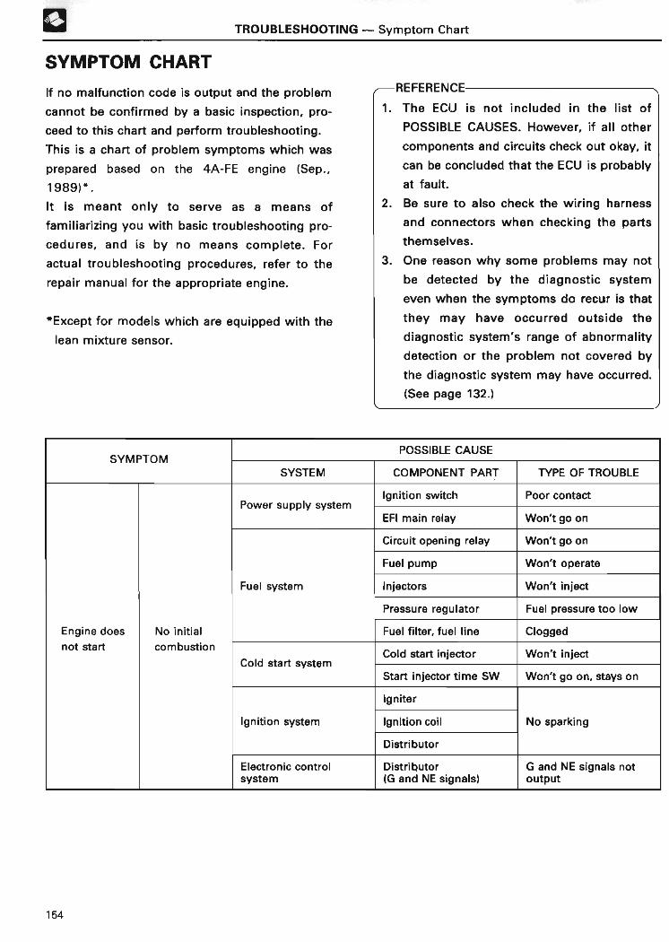
SYMPTOM CHART
TROUBLESHOOTING - Symptom Chart
If no malfunction code is output and the problem
cannot be confirmed by a basic inspection, pro-
ceed to this cha rt and pe rform troubleshooting .
This is a cha rt of problem symptoms which was
prepared based on the 4A-FE engine (Sep .,
1989)* .
It is meant only to serve as a means of
familiarizing you with basic troubleshooting pro-
cedures, and is by no means complete . For
actual troubleshooting procedures, refer to the
repair manual for the appropriate engine .
*Except for models which are equipped with the
lean mixture sensor .
REFERENCE
1 . The ECU is not included in the list o f
POSSIBLE CAUSES . However, if all other
components and circuits check out okay, it
can be concluded that the ECU is probably
at fault .
2 . Be sure to also check the wiring harness
and connectors when checking the parts
themselves .
3. One reason why some problems may not
be detected by the diagnostic system
even when the symptoms do recur is that
they may have occurred outside the
diagnostic system's range of abnormality
detection or the problem not covered by
the diagnostic system may have occurred .
(See page 132 . )
SYMPTOMPOSSIBLE CAUS E
SYSTEM COMPONENT PART TYPE OF TROUBLE
Power su l s stemIgnition switch Poor contact
pp y yEFI main relay Won't go o n
Circuit opening relay Won't go o n
Fuel pump Won't operate
Fuel system Injectors Won't inject
Pressure regulator Fuel pressure too low
Engine does No initial Fuel filter, fuel line Clogged
not sta rt combustion
Cold sta rt s stemCold sta rt injector Won't inject
ySta rt injector time SW Won't go on, stays o n
Igniter
Ignition system Ignition coil No sparking
Distributo r
Electronic contro lsystem
Distributo r(G and NE signals)
G and NE signals no toutput
154
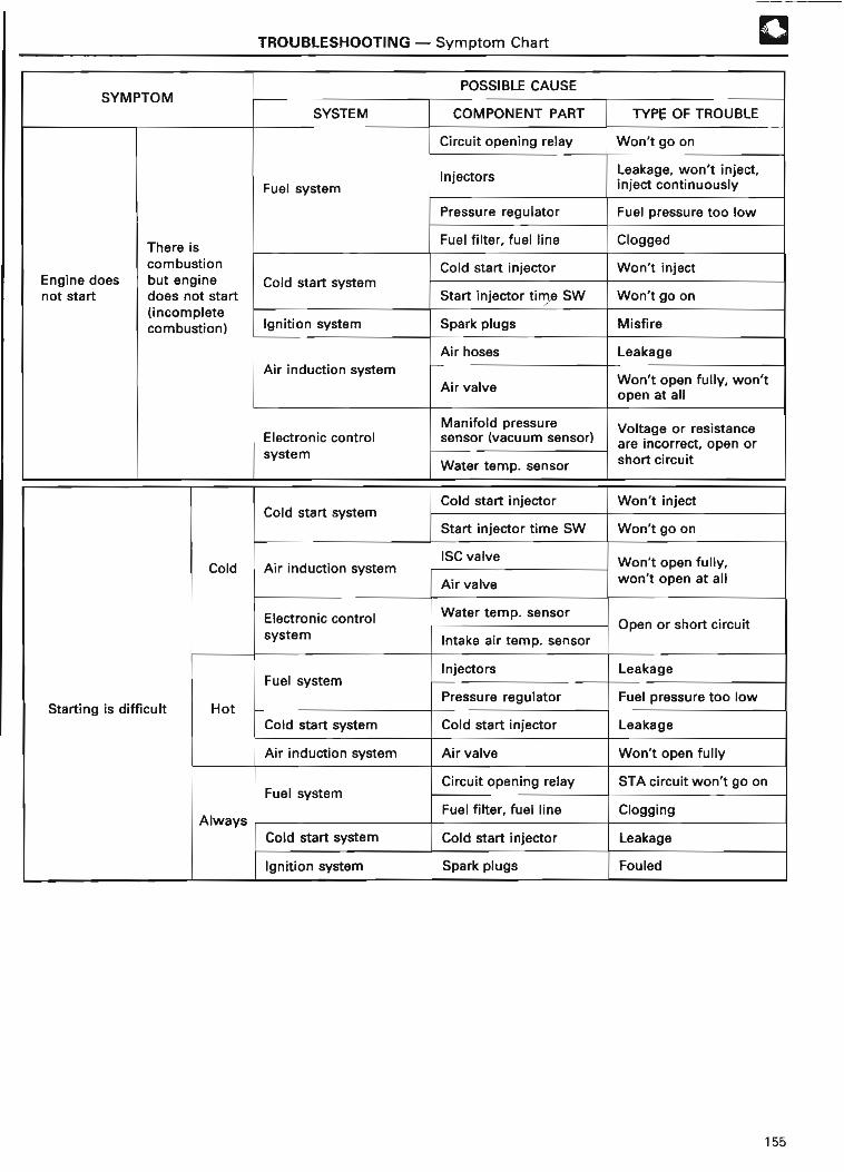
SYMPTOM
Engine doesnot start
There iscombustionbut enginedoes not start(incompletecombustion )
Start ing is difficult
Col d
Hot
Always
TROUBLESHOOTING - Symptom Chart
SYSTEM
Fuel syste m
Cold sta rt system
POSSIBLE CAUS E
COMPONENT PART
Circuit opening rela y
Injectors
Pressure regulator
Fuel filter, fuel lin e
Cold sta rt injector
Sta rt injector time SW
Ignition syste m
Air induction system
Electronic control
system
Cold sta rt system
Air induction syste m
Electronic controlsystem
Fuel syste m
Cold sta rt system
Air induction syste m
Fuel syste m
Cold start syste m
Ignition system
Spark plugs
Air hose s
Air valve
Manifold pressuresensor (vacuum sensor )
Water temp . sensor
Cold start injector
Start injector time SW
ISC valve
Air valve
Water temp. sensor
Intake air temp . sensor
Injectors
Pressure regulator
Cold sta rt injector
Air valve
Circuit opening relay
Fuel filter, fuel lin e
Cold sta rt injector
Spark plugs
TYPE OF TROUBLE
Won't go on
Leakage, won't inject,inject continuousl y
Fuel pressure too low
Clogged
Won't inject
Won't go on
Misfire
Leakage
Won't open fully, won'topen at al l
Voltage or resistanceare incorrect, open orshort circuit
Won't inject
Won't go o n
Won't open fully,won't open at al l
Open or sho rt circui t
Leakage
Fuel pressure too low
Leakage
Won't open full y
STA circuit won't go o n
Clogging
Leakage
Fouled
155

❑+~ TROUBLESHOOTING - Symptom Chart
POSSIBLE CAUS ESYMPTOM
SYSTEM COMPONENT PART TYPE OF TROUBLE
Ai induction s stemISC valve Won't open fully,
r yAir valve
won't open at al l
t id lN fas eoElectronic control Water temp. sensor Open or sho rt circuitsystem
Cold sta rt system Cold sta rt injector Leaking
Thrott le body Won't close full y
Air induction system ISC valveen continuous lSta s o yy p
Idle speed too Air valve
high Manifold pressuresensor (vacuum sensor) Voltage or resistanc e
are incorrectElectronic control Water temp . sensor
system Throttle position sensor Idle contact won't go on
Air conditioner switch Stays on continuousl y
Air induction system ISC valve Stays closed
Rough idlingManifold pressure
Voltage or resistanceIdle speed too sensor (vacuum sensor) are incorrect, open o rlow Electronic control short circuit
system Neutral sta rt switchWon't o ong
Air conditioner switc h
Fuel pump Malfunctioning
Fuel s stemInjectors Won't inject
yPressure regulator Malfunctioning
Fuel filter, fuel line Clogge d
Thrott le body Air suction
Air induction system ISC valveMalfunctioning
Air valveUnstable idling
Igniter Malfunctionin g
Ignition system Ignition coil (poor contact)
Spark plugs Misfir e
Manifold pressureMalfunctioning
Electronic control sensor (vacuum sensor )
system Thrott le position sensor Idle contact won't go o n
Oxygen (02) sensor Malfunctionin g
156

TROUBLESHOOTING - Symptom Chart
SYMPTOMPOSSIBLE CAUS E
SYSTEM COMPONENT PART TYPE OF TROUBLE
Fuel pump Drop in flow volum e
l tFInjectors Drop in injection volum e
emue sysPressure regulator Fuel pressure too low
Fuel filter, fuel line Clogged
Igniter MalfunctioningHesitatesduring Ignition system Ignition coil (poor contact )
acceleration Spark plugs Misfire
Manifold pressuresensor (vacuum sensor)
e or resistanc eVolta
Electronic controlWater temp. sensor
gare incorrect, open o r
system Intake air temp. sensorshort circui t
Thrott le position sensor
Oxygen (02) sensor Malfunctioning
Fuel pump Drop in flow volume
lF tInjectors Drop in injection volume
emue sysPressure regulator Fuel pressure too lo w
Poor drivability Fuel filter, fuel line Clogged
Igniter Malfunctionin g
Ignition system Ignition coil(poor contact )
Backfiring Spark plugs Misfire
Manifold pressuresensor (vacuum sensor)
Electronic controlWater temp . sensor Voltage or resistance
system Intake air temp . sensor are incorrect
Thrott le position senso r
Oxygen (02) sensor Malfunctionin g
Fuel system Injectors Leakage
Cold start systemCold sta rt injector Leakage, inject s
continuously
Sta rt injector time SW Stays on continuousl y
Afterfiring(muffler
Manifold pressuresensor (vacuum sensor)
Voltage or resistanceexplosions)
Electronic controlWater temp . sensor are incorrect
system Intake air temp . sensor
Throttle position sensor Idle contact won't go on
Oxygen (02) sensor Malfunctioning
157
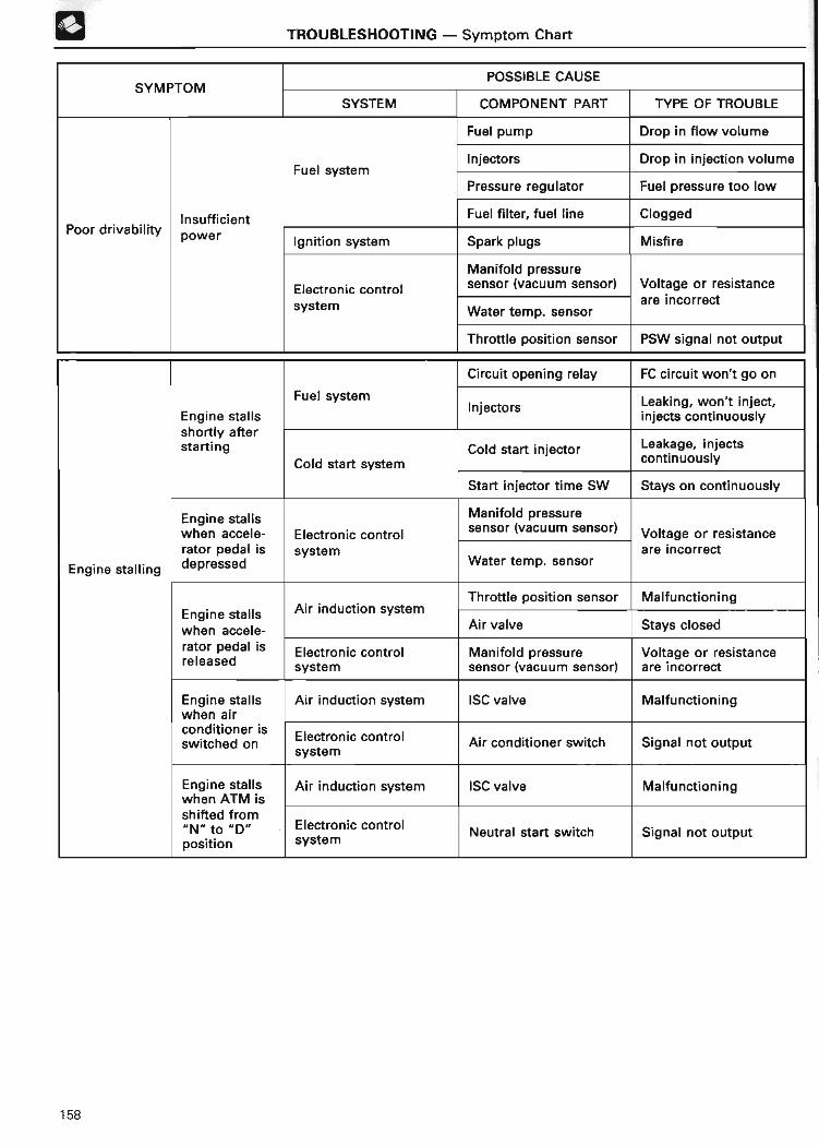
0 TROUBLESHOOTING - Symptom Chart
POSSIBLE CAUSESYMPTOM
SYSTEM COMPONENT PART TYPE OF TROUBLE
Fuel pump Drop in flow volum e
Injectors Drop in injection volum eFuel s stemy
Pressure regulator Fuel pressure too low
Insufficient Fuel filter, fuel line CloggedPoor drivability power Ignition system Spark plugs Misfire
Manifold pressure
Electronic control sensor (vacuum sensor) Voltage or resistanc e
system Water temp. sensorare incorrect
Thro ttle position sensor PSW signal not outpu t
Circuit opening relay FC circuit won't go o n
Fuel systemInjectors Leaking, won't inject ,
Engine stalls injects continuousl yshort ly aftersta rt ing Cold sta rt injector Leakage, inject s
Cold sta rt system continuousl y
Sta rt injector time SW Stays on continuously
Engine stalls Manifold pressure
when accele- Electronic controlsensor (vacuum sensor) Voltage or resistanc e
rator pedal is system are incorrect
Engine stalling depressed Water temp. senso r
Thrott le position sensor MalfunctioningAir induction s stemEngine stalls y
when accele- Air valve Stays closed
rator pedal is Electronic control Manifold pressure Voltage or resistanc ereleased system sensor (vacuum sensor) are incorrect
Engine stalls Air induction system ISC valve Malfunctioningwhen ai rconditioner i sswitched on
Electronic control Air conditioner switch Signal not outputsystem
Engine stalls Air induction system ISC valve Malfunctionin gwhen ATM isshifted fro m"N" to "D" Electronic control Neutral sta rt switch Signal not outpu tposition syste m
158
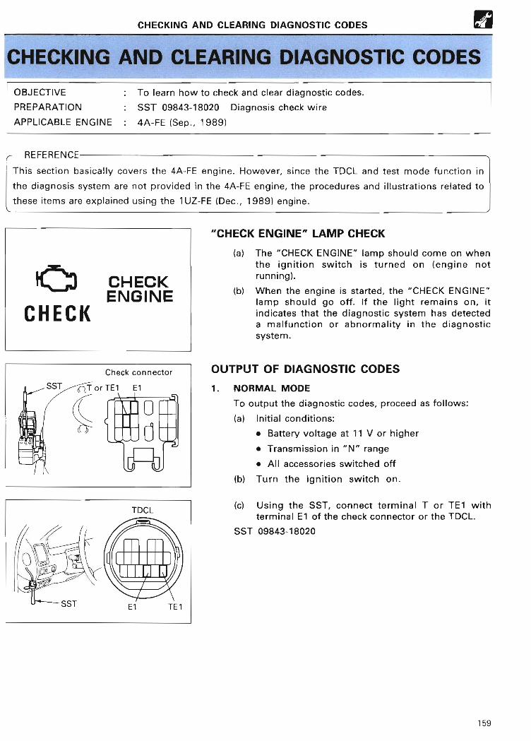
CHECKING AND CLEARING DIAGNOSTIC CODES ®
CHECKING AND CLEARING DIAGNOSTIC CODE S
OBJECTIVE : To learn how to check and clear diagnostic codes .
PREPARATION : SST 09843-18020 Diagnosis check wire
APPLICABLE ENGINE : 4A-FE (Sep ., 1989 )
/--- n~r~nuM ~~ --
This section basically covers the 4A-FE engine . However, since the TDCL and test mode function in
the diagnosis system are not provided in the 4A-FE engine, the procedures and illustrations related to
these items are explained using the 1 UZ-FE (Dec ., 1989) engine .
C~3 CHECKENGIN E
CHECK
Check connecto r
SST or TE1 El
0
TDC L
1 L
SST El TE1
"CHECK ENGINE" LAMP CHECK
(a) The "CHECK ENGINE" lamp should come on whenthe ignition switch is turned on (engine notrunning) .
(b) When the engine is started, the "CHECK ENGINE"lamp should go off . If the light remains on, itindicates that the diagnostic system has detecteda malfunction or abnormality in the diagnosticsystem.
OUTPUT OF DIAGNOSTIC CODES
1 . NORMAL MODE
To output the diagnostic codes, proceed as follows :
(a) Initial conditions :
• Battery voltage at 11 V or higher
• Transmission in "N" range
• Ail accessories switched off
(b) Turn the ignition switch on .
(c) Using the SST, connect terminal T or TE1 withterminal El of the check connector or the TDCL .
SST 09843-18020
159

n CHECKING AND CLEARING DIAGNOSTIC CODE S
CHECKENGINE~
CHECK ~ ~~
1 sec
O n
Off
0.5 sec 1 .5 se c
Start
4.5 sec 2.5 4.5 se c, ~
~lnsec~ ~
Off OI I2'eC
u u Repeat
Code 12 Code 3 1
One cycl e
SST
160
(d) Read the diagnostic code as indicated by thenumber of flashes of the "CHECK ENGINE" lamp .
DIAGNOSTIC CODES
(1) Normal code indicatio n
• The lamp will alternately blink on and off 2times per second .
(2) Malfunction code indicatio nAs an example, the blinking pa tterns for codes 12and 31 are as shown in the illustration at left .
• The lamp will blink the number of times equalto the malfunction code .It will go off for a longer period as follows :ri Once between the first and second digit of
the same code, 1 .5 seconds .`2) Once between one code and the next
code, 2 .5 seconds .3i Once between all malfunction codes, 4 .5
seconds .
NOTE :
• The diagnostic code series will be repeated a slong as check connector terminals T or TE1 andE1 are connected .
• In the event of a number of malfunction codes,indication will begin from the small value andcontinue in order to the larger value (s) .
• When the automatic transmission is in the "D","2", "L" or "R" range, or when the air condi-tioner is on, or when the accelerator pedal isdepressed, code "51" (switch condition signal)will be output, but this is normal .
(e ) After the diagnostic code check, remove the SSTfrom the check connector or the TDCL .
SST 09843-18020

SST
0 .13 sec
CHECKING AND CLEARING DIAGNOSTIC CODE S
0~~~~~~h
N I I
El TE2
l u
2. TEST MOD E
To output the diagnostic codes, proceed as follows :
(a) Initial conditions :
• Battery voltage at 11 volts or highe r
• Throttle valve fully closed (idle contact closed)
• Transmission in "N" rang e
• All accessories switched off
(b) Turn the ignition switch off.
(c) Using the SST, connect terminal TE2 with terminalEl of the TDCL .
SST 09843-1802 0
(d) Turn the ignition switch on .
NOTE : To confirm that the test mode is operating,see whether the "CHECK ENGINE" lamp blinkswhen the ignition switch is turned on .This blinking cycle is faster than blinking cycle ofnormal code.
(e) Start the engine .
(f) Simulate the conditions of the malfunctiondescribed by the customer .
If the diagnostic system detects a malfunction, the"CHECK ENGINE" lamp will go on .
(g) After performing a road test, connect terminal TE1with terminal El of the TDCL using the SST.
SST 09843-1802 0
(h) Read the diagnostic code as indicated by thenumber of times the "CHECK ENGINE" lampblinks .
NOTE : The method used to read the diagnosticcode is the same as in the normal mode .
(i) After completing this check, remove the SSTs fromthe TDCL .
SST 09843-18020
NOTE :
• The test mode will not start if terminals TE2 an dEl are connected after the ignition switch isturned on .
• If the engine is not cranked, diag . code "43"(starter signal) will be output, but this is normal .
• When the automatic transmission is in the "D" ,"2", "L" or "R" range, or when the air con-ditioner is on, or when the accelerator pedal isdepressed, code "51" (switch condition signal)will be output, but this is normal .
161

STOP(1 5A)
CHECKING AND CLEARING DIAGNOSTIC CODE S
CLEARING DIAGNOSTIC COD E
(a) After the trouble is repaired, the diagnostic coderetained in memory by the Engine ECU must becleared by removing the STOP (15 A) fuse or EFI(15 A) fuse for 10 seconds or longer, depending onthe ambient temperature (the lower thetemperature, the longer the fuse must be left out)with the ignition switch off .
NOTE :
• Clearing the memory can also be done byremoving the ba ttery cable from the negativeterminal, but in this case other memo ry systems(radio, clock, etc .) will also be cleare d
• If it is necessa ry to work on engine componentsrequiring removal of the cable from the batteryterminal, a check must first be made to see ifany diagnostic codes have been recorded .
(b) After clearing the memory, pe rform a road test toconfirm that a "normal" code can now be read .
If the same diagnostic code as before appears, itindicates that the trouble has not been completelyremedied .
162

SYMPTOM SIMULATION
SYMPTOM SIMULATIO N
The most difficult problems in troubleshooting
are intermittent problems: that is, problems
about which the customer has a complaint, but
which do not occur or cannot be comfirmed in
the service shop . Intermittent problems often
include complaints about the "CHECK ENGINE"
lamp going on and off erratically .
To ensure accurate diagnosis of such problems,
ask the customer to provide as much information
as possible .
To do this, question the customer closely about
the problem, using the Pre-diagnostic
Questioning Checksheet, then try to reproduce
the problem on the customer's vehicle .
The symptom simulation methods (applying
vibration, heat, or humidity) described below are
effective ways of reproducing the symptoms for
problems of this nature.
OBJECTIVE To learn how to reproduce intermi ttent problems
PREPARATIO N
APPLICABLE ENGIN E
1
Terminals have sprea d
VIBRATION METHOD: When vibration seems to be the major cause .
CONNECTORS
Gently shake the connectors vertically and hori-
zontally and pull on them :
(a) Are they loose ?
(b) Does the wire harness have enough slack?
Watch especially for :
• Dirty terminals• Loose contact due to spreading of terminals
163

Wt SYMPTOM SIMULATION
VIBRATION METHOD (cont'd) : When vibration seems to be the major cause.
WIRE HARNES S
Gently wiggle the wire harness vertically an d~ r
horizontally . Connector joints and places where wir e
harnesses pass through the body are the major area s
to be checked .
Gently wiggl e
Gently tap PARTS AND SENSORS
Gently tap the part or sensor in question with you r
finger .
NOTE R b h l i: emem er t at app y ng too much shock to a
J~~ JJ l relay may cause it to open, making it appear that it i s
the relay that is at fault when there is really nothin g
wrong with it at all .
::2] HEAT METHOD: When the malfunction seems to occur when the suspec tarea is heated .
Using a hair dryer, heat the component that is the
likely cause of the malfunction .Malfunc -tions NOTICE :
D h °C• o not eat any component to more than 60
(140°F) ( temperature limit at which the componen t
can be safely touched with the hand) .
• Never open an ECU and apply heat directly to th e
parts inside it .
3 WATER SPRAY METHOD: When the malfunction seems to occur on a rainy
day or under conditions of high humidity .
Change the temperature and ambient humidity b y
spraying water onto the vehicle .
NOTICE :
• Never spray water directly into the engin e
compartment; spray it onto the front of the radiator
through the grill .
• Never let water come in direct contact wit h
electronic components .
NOTE :
• If a vehicle is subject to water leakage, the leaking
water may get into an ECU . When testing a vehicl e
with a water leakage problem, special caution must
be used.
164
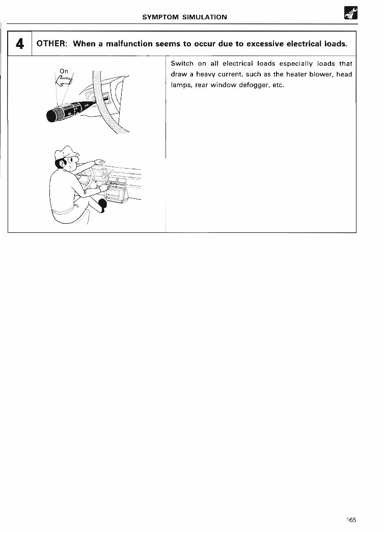
SYMPTOM SIMULATION ®
4 OTHER : When a malfunction seems to occur due to excessive electrical loads .
Switch on all electrical loads especially loads thatOn draw a heavy current, such as the heater blower, hea d
I i lamps, rear window defogger, etc .
Irv,
,-~,:.----.=~~`_,?
165

W BASIC INSPECTIO N
BASIC INSPECTIO N
When the "normal" code is displayed during thediagnostic code check, troubleshooting should beperformed in the correct order for all possiblecircuits considered to be the causes of theproblems .
NO ) Go to step
OBJECTIVE . To learn how to carry out basic inspection of the engine .
PREPARATIONS .• SST 09843-18020 Diagnosis check wire
• Engine tune-up tester (tachometer, timing light)
APPLICABLE ENGINE : 4A-FE* (Sep ., 1989 )
*Except Carina 11 (AT 17 1) with lean mixture senso r
1 Is battery voltage 11 V or more when engine is stopped?
NO j Charge or replace battery .
2 Does engine crank?
NO ) Go to Symptom Cha rt (see page 154) .
3
0
0 Visually check to see whether the air cleane r
Does engine sta rt?
Check air filter .
NOTE
In many cases, carrying out the basic engine
check shown in the following flow chart will
allow you to locate the cause of the problemquickly and efficiently . For this reason, it is
essential to perform this inspection beforetroubleshooting engine problems .
8
Remove the air filter .
element is excessively dirty, oily or damaged .
If necessary, clean the element withcompressed air : first blow from the insidethoroughly, then blow off the outside of theelement .
N G ~ Replace air cleaner element .
Procedure 0 Check or inspectio n
167

BASIC INSPECTIO N
5 Is air leaking into air intake system?
Check idle speed .
Tachometer
•m
Check for air leaking into the air intake system.
If the engine oil dipstick, oil filler cap or PCVhose, etc. is loose or missing, air can leak intothe air intake system, causing the air-fuelmixture to become too lean .
No air leaking into the air intake systembetween the air flow meter and the cylinderhead .
N G Repair air leakage .
( 1) Shift the transmission into the " N" range.(2) Warm up the engine to its normal operating
temperature .(3) Switch off all accessories .(4) Switch off the air conditioner .(5) Connect a tachometer test probe to the IG
e terminal of the check connector .
0 Check the idle speed.
O K
NO 1I LE
Idle speed: 800 rpm (cooling fan off )
• NEVER allow the tachometer test probe totouch ground as it could result in damage tothe igniter and/or ignition coil .
• As some tachometers are not compatiblewith this ignition system, we recommendthat you confirm the compatibility of yourunit before use .
N G Adjust idle speed.
7 Check ignition timing .
~ (1) Connect the timing light to the engine .
®(2) Run the engine at an idle.
SST~~ (3) Using the SST, connect terminal TE1 wit hEl terminal El of the check connector .
SST 09843-1802 0
TE1*
Check co
_
nnecto
168

BASIC INSPECTIO N
7 Check ignition timing (cont'd) .
© Check the ignition timing using a timing light .
•m Ignition timing : 10° BTDC (engine idling )
Transmission in the "N" range .
Pr ~ ~
r~~'~ . TI✓ ~ .d_
, L✓ ,' ~ iy
FURTHER CHECK
0 Disconnect the SST .
SST SST 09843-18020
0 Use a timing light to check whether the ignitio ntiming advances properly .
Ignition timing : the timing mark moves no morethan 5° on each side of the 10° mark.
Transmission in the "N" range .
OK NG Adjust ignition timing .
Go to Symptom Chart (See page 154) .
169

BASIC INSPECTION W
8 Check fuel pressure .
~ (1) Be sure that there is enough fuel in th etank .
~(2) Turn the ignition switch on .
SST (3) Using the SST, connect terminal +B witho p
6E6iterminal FP of the check connector .
SST 09 3FP + g 84 -1802 0
'- 0 Check if there is pressure in the hose from theCheck fuel filter by pinching the hose with you rconnector fingers.
~ You should hear the sound of fuel passin gthrough the fuel return hose .
M3 Fuel pressure can be felt .
~~
OK NG Repair EFI system . (See Step 2, vol . 5, "EFI" . )
Check for sparks .
Repair ignition system . (See Step 2, vol. 3~N G "Ignition System" . )
Go to Symptom Chart (See page 154) .
170
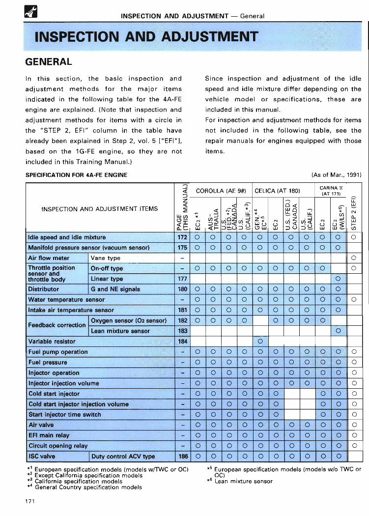
W INSPECTION AND ADJUSTMENT - Genera l
INSPECTION AND ADJUSTMEN T
GENERAL
In this section, the basic inspection and
adjustment methods for the major items
indicated in the following table for the 4A-FE
engine are explained . (Note that inspection and
adjustment methods for items with a circle in
the "STEP 2, EFI" column in the table have
already been explained in Step 2, vol . 5("EFI"],
based on the 1G-FE engine, so they are not
included in this Training Manual . )
SPECIFICATION FOR 4A-FE ENGINE (As of Mar., 1991 )
? COROLLA (AE 9#) CELICA (AT 180) ~AT NA ; i
INSPECTION AND ADJUSTMENT ITEMSzaCC
LU u)
Q =d F
UW
I Q
Z) =QF
a# 0
N ~~LL
"LL
Q7 V
*
I( 7 WUW
o aLL Q
NaZ) U
-LL
6 a=i UUW
~
U J>W?
wC14
HU)Idle speed and idle mixture 172 0 0 0 0 0 0 0 0 0 0 0Manifold pressure sensor (vacuum sensor) 175 0 0 0 0 0 0 0 0 0 0Air flow meter Vane type - 0Throttle positio n
d On-off type - 0 0 0 0 0 0 0 0 0 0sensor a nthrottle body Linear type 177 0Distributor G and NE signals 180 0 0 0 0 0 0 0 0 0 0Water temperature sensor - 0 0 0 0 0 0 0 0 0 0 0Intake air temperature sensor 181 0 0 0 0 0 0 0 0 0 0
Feedback correctionOxygen sensor ( O2 sensor) 182 0 0 0 0 0 0 0 0Lean mixture sensor 183 0
Variable resistor 184 0Fuel pump operation - 0 0 0 0 0 0 0 0 0 0 0Fuel pressure - 0 0 0 0 0 0 0 0 0 0 0Injector operation - 0 0 0 0 0 0 0 0 0 0 0Injector injection volume - 0 0 0 0 0 0 0 0 0 0 0Cold sta rt injector - 0 0 0 0 0 0 0 0 0Cold sta rt injector injection volume - 0 0 0 0 0 0 0 0 0Sta rt injector time switch - 0 0 0 0 0 0 0 0 0Air valve - 0 0 0 0 0 0 0 0 0 0 0EFI main relay -
0 0 0 0 0 0 0 0 0 0 0
Circuit opening relay - 0 0 0 0 0 0 0 0 0 0 O
ISC valve Duty control ACV type 186 0 0 0 0 0 0 0 0 0 0
* 1 European specification models ( models w/TWC or OC)*2 Except California specification models*3 California specification model s*4 General Country specification models
Since inspection and adjustment of the idle
speed and idle mixture differ depending on the
vehicle model or specifications, these are
included in this manual .
For inspection and adjustment methods for items
not included in the following table, see the
repair manuals for engines equipped with those
items .
*5 European specification models (models w/o TWC orOC )
*6 Lean mixture senso r
171

INSPECTION AND ADJUSTMENT - Idle Speed and Idle Mixture
IDLE SPEED AND IDLE MIXTUR E
OBJECTIVE : To learn the procedure for inspecting and adjusting the idle speed and idle
mixture .
PREPARATIONS : • SST 09843-18020 Diagnosis check wire
• Tachometer • CO meter
APPLICABLE ENGINE : 4A-FE ( Sep., 1989 )
1 . INITIAL CONDITIONS(a) Air cleaner installed(b) All pipes and hoses of the air induction system
connected(c) All vacuum lines connected
NOTE: All vacuum hoses for the EGR system, etc .,should be properly connected .
(d) All accessories switched off
(e) EFI system wiring connectors securely connected(f) Ignition timing correctly set(g) Transmission in "N" range
2. WARM UP ENGINEAllow the engine to reach its normal operatingtemperature .
3. CONNECT TACHOMETE RConnect the test probe of a tachometer to the IG ~terminal of the check connector.
NOTICE :• NEVER allow the tachometer terminal to touch
ground as it could result in damage to the igniterand/or ignition coil .
• As some tachometers are not compatible with thisignition system, we recommend that you confirmthe compatibility of your unit before use .
4. CHECK AIR VALVE OPERATION
5. CHECK AND ADJUST IDLE SPEE D(a) Race the engine at 2,500 rpm for about 90 seconds .(b) Using the SST, connect terminal T or TE1 with
terminal El of the check connector .
SST 09843-18020(c) Check the idle speed .Idle speed (cooling fan off) :
2WD (Federal U.S. and Canada) 700 rpmOthers 800 rpm
If not as specified, adjust the idle speed by turning theidle speed adjusting screw.
NOTE: For Federal U .S. and Canada 2WD manualtransmission vehicles with the Daytime Running LightSystem, the idle speed should rise to 800 rpm .
172
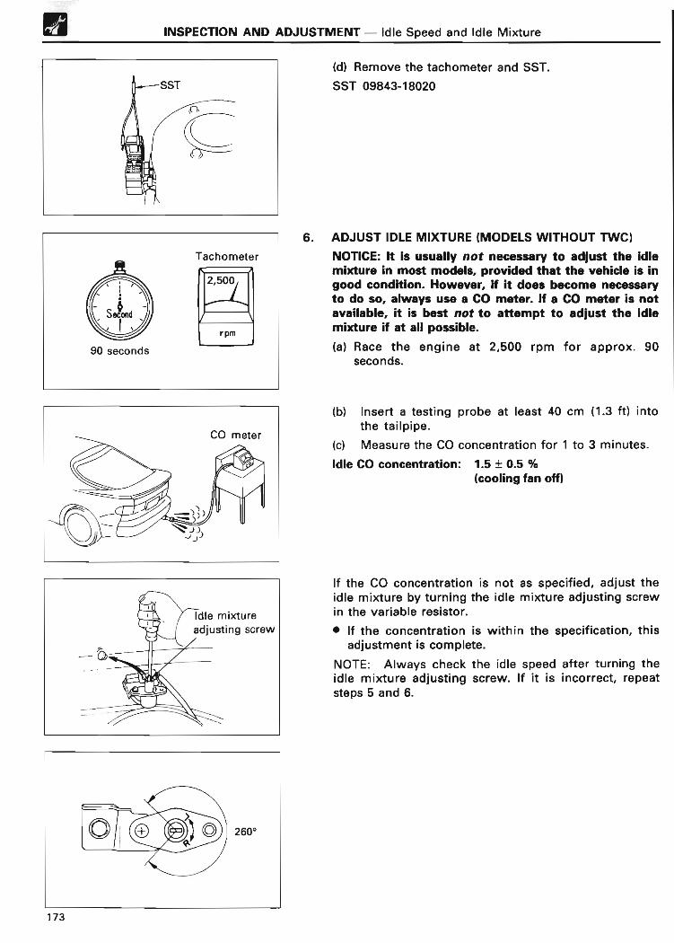
W INSPECTION AND ADJUSTMENT - Idle Speed and Idle Mixtur e
(d) Remove the tachometer and SST.
SST 09843-1802 0
6. ADJUST IDLE MIXTURE (MODELS WITHOUT TWC)
NOTICE: It is usually not necessa ry to adjust the idlemixture in most models, provided that the vehicle is ingood condition . However, if it does become necessa ryto do so, always use a CO meter. If a CO meter is notavailable, it is best not to attempt to adjust the idlemixture if at all possible .(a) Race the engine at 2,500 rpm for approx. 90
seconds .
(b) Insert a testing probe at least 40 cm (1 .3 ft) intothe tailpipe .
(c) Measure the CO concentration for 1 to 3 minutes .
Idle CO concentration : 1 .5 ± 0.5 %(cooling fan off )
If the CO concentration is not as specified, adjust theidle mixture by turning the idle mixture adjusting screwin the variable resistor .
• If the concentration is within the specification, thisadjustment is complete .
NOTE: Always check the idle speed after turning theidle mixture adjusting screw . If it is incorrect, repeatsteps 5 and 6 .
173

INSPECTION AND ADJUSTMENT - Manifold Pressure Sensor (Vacuum Sensor )
MANIFOLD PRESSURE SENSOR (VACUUM SENSOR)
OBJECTIVE To learn the procedure for inspecting the manifold pressure sensor (vacuum
sensor) .PREPARATIONS .• Voltmeter (also called "circuit tester" or "multi-tester")
• Mityvac ( hand-held vacuum pump )
APPLICABLE ENGINE : 4A-FE* (Sep ., 1989 )
*Except Carina 11 (AT 171) with lean mixture senso r
Vacuum chamber
E2
PIM
VC
~
From intake manifold
INSPECTION OF MANIFOLD PRESSURE SENSOR(VACUUM SENSOR )
1 . CHECK POWER SOURCE VOLTAGE OF MANIFOLDPRESSURE SENSO R
(a) Disconnect the manifold pressure sensor connector .
(b) Turn the ignition switch on .
(c) Using a voltmeter, measure the voltage betweenterminals VC and E2 of the manifold pressure sensorconnector .
Voltage: 4 - 6 V
2. CHECK POWER OUTPUT OF MANIFOLD PRESSURESENSOR
(a) Turn the ignition switch on .
(b) Disconnect the vacuum hose at the intake chamberside .
(c) Connect a voltmeter to terminals PIM and E2 of theECU, and measure and record the output voltageunder the ambient atmospheric pressure .
(d) Using a Mityvac (hand-held vacuum pump), applyvacuum to the manifold pressure sensor inincrements of 13 .3 kPa (100 mmHg, 3 .94 in.Hg) untilthe vacuum reaches 66.7 kPa (500 mmHg, 19 .69in.Hg) .
175

®
2WD
Voltmeter
v
O
4WD
INSPECTION AND ADJUSTMENT - Manifold Pressure Sensor (Vacuum Sensor )
ECU PIM
~ooooo000 ❑❑aoooaoooooy~o~
U-E2
; i mr~dno~j 11 _ :_]~ ~0 ❑
(e) Measure the voltage drop at each stage .
Voltage drop
APPLIED 13 .3 26 .7 40 .0 53.3 66 7VACUUM
.
kPag
100(
20( 0 ) 30( 1)
400( ) ( ~ )\ in .Hg J 3 .94 J 7 .8 7 11 .8 15. 5 19 69
Voltagedrop (V) 0.3-0.5 0.7-0.9 1 .1 -1 .3 1 .5-1 .7 1.9-2. 1
176
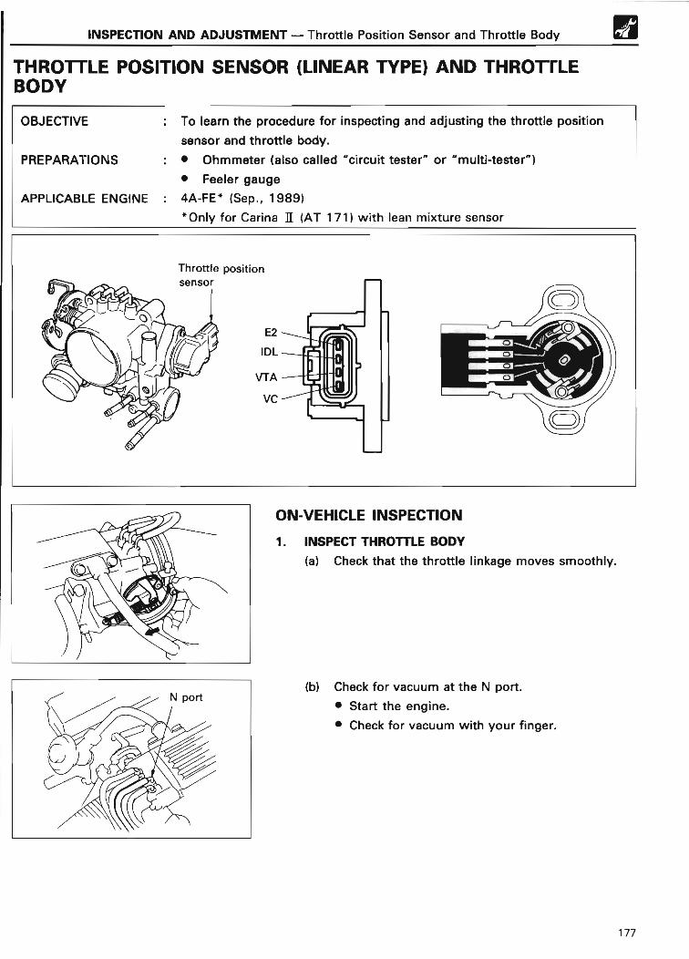
INSPECTION AND ADJUSTMENT - Throttle Position Sensor and Throttle Body
THROTTLE POSITION SENSOR (LINEAR TYPE) AND THROTTLEBODY
OBJECTIVE : To learn the procedure for inspecting and adjusting the throttle position
sensor and throttle body .
PREPARATIONS :• Ohmmeter (also called "circuit tester" or "multi-tester")
• Feeler gauge
APPLICABLE ENGINE : 4A-FE* (Sep ., 1989 )
*Only for Carina 11 (AT 171) with lean mixture senso r
ON-VEHICLE INSPECTION
®
1 . INSPECT THROTTLE BOD Y
(a) Check that the throttle linkage moves smoothly .
(b) Check for vacuum at the N po rt .
• Sta rt the engine .
• Check for vacuum with your finger .
177
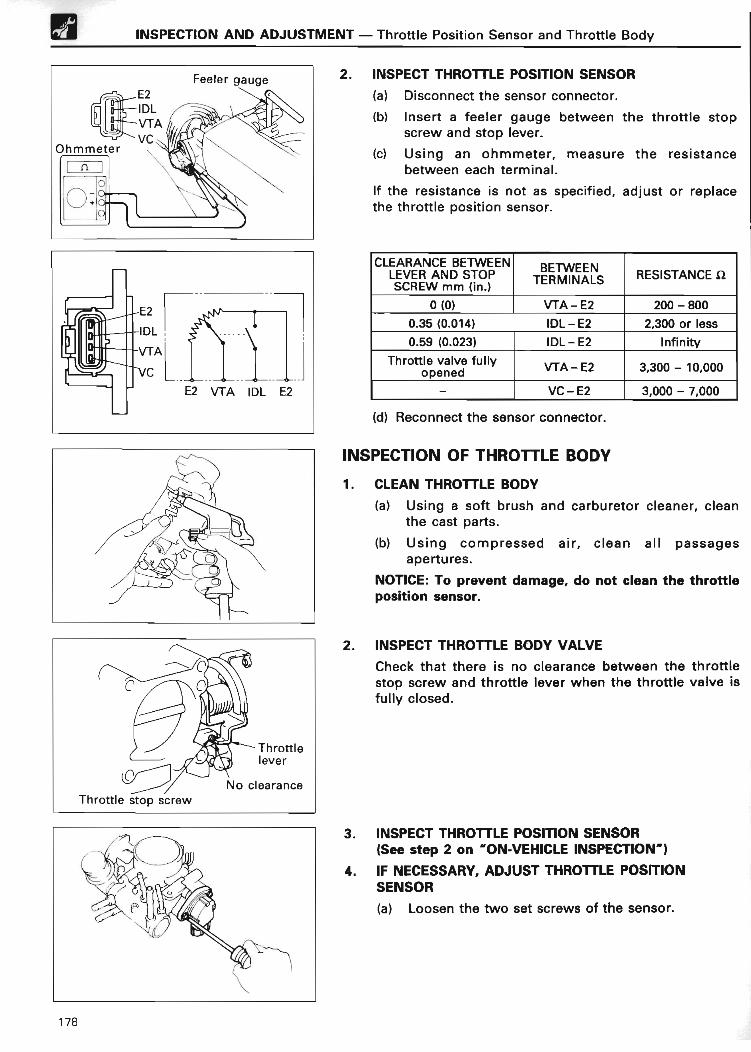
W INSPECTION AND ADJUSTMENT - Throttle Position Sensor and Throttle Bod y
E2
IDL
VTA
E2 VTA IDL E2
2. INSPECT THROTTLE POSITION SENSOR
(a) Disconnect the sensor connector .
(b) Insert a feeler gauge between the throttle stopscrew and stop lever.
(c) Using an ohmmeter, measure the resistancebetween each terminal .
If the resistance is not as specified, adjust or replacethe throttle position sensor.
CLEARANCE BETWEEN BETWEENLEVER AND STOP TERMINALS RESISTANCE S2SCREW mm (in . )
0(0) VTA - E2 200 - 800
0.35 (0 .014) IDL - E2 2,300 or less
0.59 (0 .023) IDL - E2 Infinit y
Throttle valve full yopened y fA-E2 3,300 - 10,00 0
- VC-E2 3,000 - 7,00 0
(d) Reconnect the sensor connector .
INSPECTION OF THROTTLE BODY
1 . CLEAN THROTTLE BOD Y
(a) Using a soft brush and carburetor cleaner, cleanthe cast parts .
(b) Using compressed air, clean all passagesapertures .
NOTICE: To prevent damage, do not clean the throttleposition sensor .
2. INSPECT THROTTLE BODY VALV E
Check that there is no clearance between the throttlestop screw and throttle lever when the throttle valve isfully closed .
3 . INSPECT THROTTLE POSITION SENSOR(See step 2 on "ON-VEHICLE INSPECTION" )
4. IF NECESSARY, ADJUST THROTTLE POSITIONSENSOR
(a) Loosen the two set screws of the sensor .
178
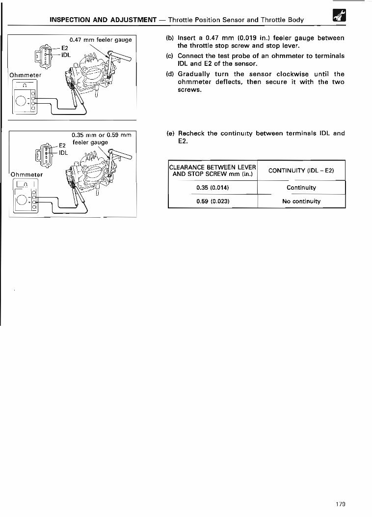
INSPECTION AND ADJUSTMENT - Throttle Position Sensor and Throttle Body W
(b) Insert a 0 .47 mm (0 .019 in .) feeler gauge betweenthe throttle stop screw and stop lever.
(c) Connect the test probe of an ohmmeter to terminalsIDL and E2 of the sensor .
(d) Gradually turn the sensor clockwise until theohmmeter deflects, then secure it with the twoscrews .
(e) Recheck the continuity between terminals IDL andE2 .
CLEARANCE BETWEEN LEVERCONTINUITY (IDL - E2 )
AND STOP SCREW mm (in . )
0 .35 (0 .014) Continuity
0.59 (0 .023) No continuity
179
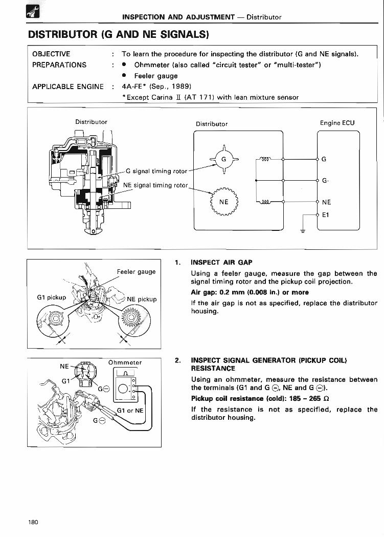
INSPECTION AND ADJUSTMENT - Distributo r
DISTRIBUTOR (G AND NE SIGNALS )
OBJECTIVE . To learn the procedure for inspecting the distributor (G and NE signals) .
PREPARATIONS :• Ohmmeter (also called "circuit tester" or "multi-tester" )
• Feeler gauge
APPLICABLE ENGINE : 4A-FE* (Sep ., 1989)
*Except Carina II (AT 171) with lean mixture senso r
1 . INSPECT AIR GAP
Using a feeler gauge, measure the gap between thesignal timing rotor and the pickup coil projection .
Air gap: 0.2 mm (0.008 in .) or more
If the air gap is not as specified, replace the distributorhousing .
2. INSPECT SIGNAL GENERATOR (PICKUP COIL)RESISTANC E
Using an ohmmeter, measure the resistance betweenthe terminals (G1 and G G, NE and G 6) .
Pickup coil resistance (cold) : 185 - 265 S2
If the resistance is not as specified, replace thedistributor housing.
180

INSPECTION AND ADJUSTMENT - Intake Air Temperature Senso r
INTAKE AIR TEMPERATURE SENSO R
OBJECTIVE To learn the procedure for inspecting the intake air temperature sensor .
PREPARATION . Ohmmeter ( also called "circuit tester" or "multi-tester" )
APPLICABLE ENGINE 4A-FE (Sep ., 1989 )
Thermistor
-20 0 20 40 60 80 100 120(-4) (32) (68) (104) (140) (176) (212) (248 )
Temperature °C (°F)
W
INSPECTION OF INTAKE AIR TEMPERATURE SENSO R
Using an ohmmeter, measure the resistance betweenthe terminals .
Resistance: Refer to the chart above.
If the resistance is not as specified, replace the sensor .
181
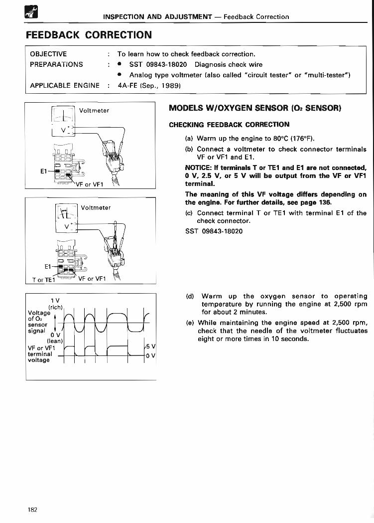
INSPECTION AND ADJUSTMENT - Feedback Correction
FEEDBACK CORRECTION
OBJECTIVE : To learn how to check feedback correction.
PREPARATIONS : • SST 09843-18020 Diagnosis check wir e
• Analog type voltmeter ( also called "circuit tester" or "multi-tester")
APPLICABLE ENGINE : 4A-FE ( Sep., 1989)
MODELS W/OXYGEN SENSOR (02 SENSOR)
CHECKING FEEDBACK CORRECTIO N
(a) Warm up the engine to 80°C (176°F) .
(b) Connect a voltmeter to check connector terminalsVF or VF1 and E1 .
NOTICE: If terminals T or TE7 and E7 are not connected,0 V, 2.5 V, or 5 V will be output from the VF or VF1terminal .
The meaning of this VF voltage differs depending onthe engine . For fu rther details, see page 136 .
(c) Connect terminal T or TE1 with terminal El of thecheck connector .
SST 09843-18020
(d) Warm up the oxygen sensor to operatingtemperature by running the engine at 2,500 rpmfor about 2 minutes .
(e) While maintaining the engine speed at 2,500 rpm,check that the needle of the voltmeter fluctuateseight or more times in 10 seconds.
182

INSPECTION AND ADJUSTMENT - Feedback Correction
MODELS W/LEAN MIXTURE SENSOR
CHECKING FEEDBACK CORRECTIO N
(a) Warm up the engine to 80°C (176°F) .
(b) Connect a voltmeter to check connector terminalsVF or VF1 and El .
(c) Connect terminal T or TE1 with terminal El of thecheck connector.
SST 09843-18020
(d) Warm up the lean mixture sensor to operatingtemperature by running the engine at idle for atleast 10 minutes .
(e) To start feedback correction, race the engine at3,500 rpm, then repeat 20 seconds later.
(f) While the maintaining engine speed at 1,500 rpm,check the VF terminal voltage .
0 V: Air-fuel ratio feedback correction istaking place
2.5 V or 5 V : Air-fuel ratio feedback correction isnot taking place
183

INSPECTION AND ADJUSTMENT - Variable Resisto r
VARIABLE RESISTO R
OBJECTIVE : To learn the procedure for inspecting the variable resistor.PREPARATION : Volt- and ohmmeter (also called "circuit tester" or "multi-tester")
APPLICABLE ENGINE : 4A-FE (Sep ., 1989)
INSPECTION OF VARIABLE RESISTOR
1 . INSPECT VOLTAGE OF VARIABLE RESISTO R
(a) Using a voltmeter, measure the voltage betweenECU terminals VC and E2 .
Voltage: 4 - 6 V
(b) Measure the voltage between ECU terminals VAFand E2 while slowly turning the idle mixtureadjusting screw, first fully counterclockwise, thenfully clockwise .
184
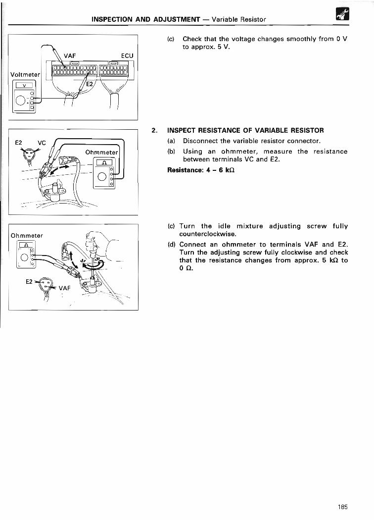
Voltmeter
Ov
00
+o0
E2
-4-,~JIJJC_ii7~C_~i~r_n,r~poo
(c) Check that the voltage changes smoothly from 0 Vto approx. 5 V .
2 . INSPECT RESISTANCE OF VARIABLE RESISTOR
(a) Disconnect the variable resistor connector .
(b) Using an ohmmeter, measure the resistancebetween terminals VC and E2 .
Resistance: 4 - 6 kS2
(c) Turn the idle mixture adjusting screw fullycounterclockwise .
(d) Connect an ohmmeter to terminals VAF and E2 .Turn the adjusting screw fully clockwise and checkthat the resistance changes from approx . 5 kS2 to052.
185
INSPECTION AND ADJUSTMENT - Variable Resistor
ECU
O00 000ooooory
❑ooooo000000~
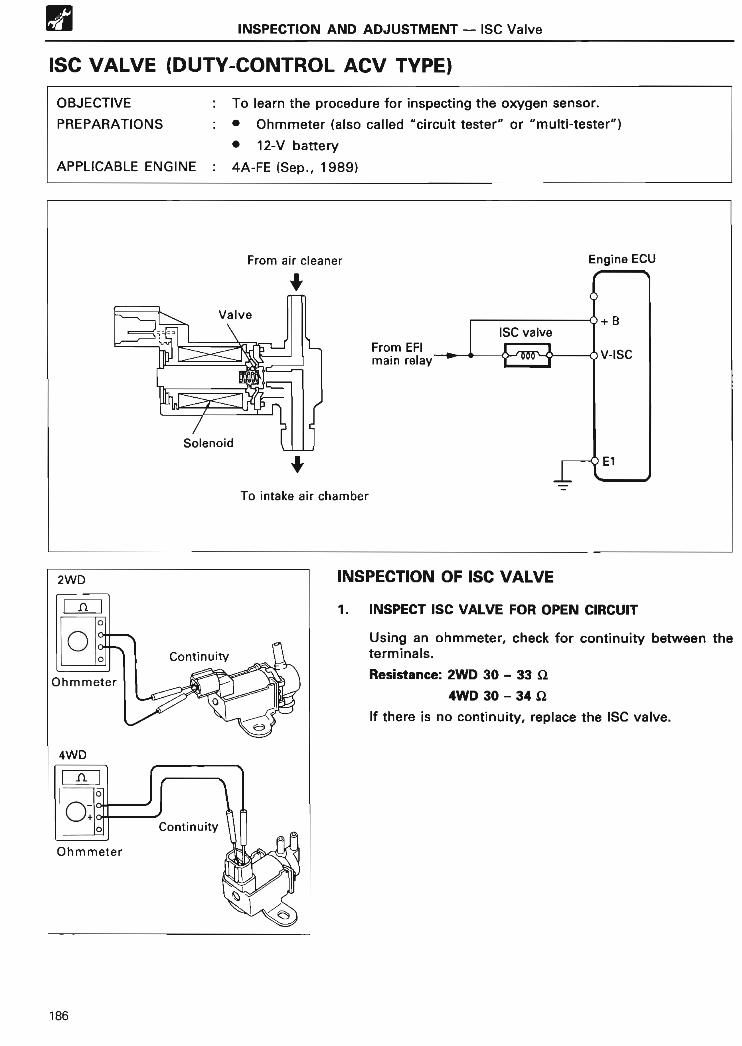
W INSPECTION AND ADJUSTMENT - ISC Valve
ISC VALVE (DUTY-CONTROL ACV TYPE )
OBJECTIVE : To learn the procedure for inspecting the oxygen sensor .
PREPARATIONS . • Ohmmeter ( also called "circuit tester" or "multi-tester")
• 12-V battery
APPLICABLE ENGINE : 4A-FE (Sep ., 1989)
INSPECTION OF ISC VALVE
1 . INSPECT ISC VALVE FOR OPEN CIRCUIT
Using an ohmmeter, check for continuity between theterminals .
Resistance: 2WD 30 - 33 S2
4WD 30 - 34 12
If there is no continuity, replace the ISC valve .
186

INSPECTION AND ADJUSTMENT - ISC Valve
2 . INSPECT ISC VALVE FOR GROUNDING
W
Using an ohmmeter, check that there is no continuitybetween each terminal and body.
If there is continuity, replace the ISC valve .
3 . INSPECT ISC VALVE OPERATION
(a) Check that air does not flow from pipe E to pipe F .
(b) Apply battery voltage across the terminals .
(c) Check that air flows from pipe E to pipe F .
If operation is not as specified, replace the ISC valve .
187

APPENDIX
ENGINE CONTROL SYSTEM SPECIFICATION CHART
ENGINE ENGINEG SIGNALS THROTTLE FUEL FEEDBACK
ELECTRONIC
SPARK KNOCKIDLE SPEE DCONTROL VALV E
MODELCONTROL
1 NE SIGNAL•2 POSITIONPATTERNIN T ON EC
ADVANCE CONTROL AND/O RCONTROL'S AIR VALV E
1UZ-FE TCCSL-EF I
(KS)
G1, G2 (1 )NE (12) Linear type 4 groups
With o rWithout
With With Stepper moto r
L-EFI
jIndependent
j j(VG) (Sequential )
3VZ-FE TCCSL-EFI G1, G2 (1) Linear typeype
With or With With Stepper moto r( ~VS) NE (24) (Sequential) Withou t
3VZ-E TCCSL-EF I
VSG1, G2 (1 )
NE (24) Linear type Simultaneous With With With Thermo wax ai r(L ) valve
5VZ-FE TCCS L-EFI G(1) Linear type Independent With With (DIS) With Rotary solenoi d(VG) NE (36-2) (Sequential) valve
1 MZ-FE TCCSL-EFI G(1 )
Linear type Independent With or With (DIS) WithRotary solenoi d
(VG) NE (36-2 ) (Sequential) Without valve
2JZ-GE TCCSL-EF I(KSI
G1, G211 1NE (24)
Linear type (Sequential) With With With Stepper moto r
D-EFI
j jWith or
j(PIM) Without
j 3 groups Without j j j
L-EFI G1,G2(1 )NE 1241
IndependenthW(VG) NE2 (36-2) (Sequential) it T
2JZ-GTE TCCSL-EF I(VG )
G1, G2 ( 1 )NE (12) Linear type
Independen t
(Sequential)With With (DIS) With Stepper moto r
1G-FE EFIL-EF I1 SVS)
Without IDL, TL, PSW Simultaneous Without Without WithoutThermowaxai r
valve
3S-FE TCCSL-EFI G (4) Linear type or
SimultaneousWith or With Without
Rotary solenoi d( l,VSI NE (24 ) IDL, E, PSW Without valve
D-EFIIDL, E PSW T Without t VSV & Therm o
(PIM) ,wax air valv e
G (1) Linear type 2 groups With or With Rotary solenoi dNE (4) Without valve
j NE (4) j Simultaneous With j j t
Gil)j
Independent
j 1NE (36-2) (Sequential )
3S-GE TCCSL-EFI G1, G2 (1)
Linear typeIndependent With or With Without VSV & Therm o
( ( ,VS) NE (24) (Sequential) Without wax air valve
1 ? With Rotary solenoidvalve
D-EFI j
Tj j j j j
(PIM )
" For notes, see page 190 .
188

ENGINE ENGINE G SIGNALS THROTTLE FUEL FEEDBACKELECTRONICSPARK KNOCK
IDLE SPEEDCONTROL VALVE
MODELCONTROL
.NESIGNAL2
POSITION INJECTION CORREC-ADVANCE CONTROL AND/OR
SYSTEM" SENSOR*3 PATTERN TION*4CONTROL`5 AIR VALV E
3S-GTE TCCSL-EFI G1, G2 (1)
Linear typeIndependen t
iS l) With With WithRotary solenoi d
valv e( (,VS) NE ( 24) equent a(
D-EFI ? j(PIM )
5S-FE TCCSD-EFI G (4) Linear type
SimultaneousWith o r
Wi hWith Without
Rotary solenoidl( PIM) NE (24) or IDL, E, PSW t out v eva
G(1)Linear type 2 groups r Wit h
NE (4)
G1, G2 ( 1 ) Independent With jNE (24) (Sequential )
G(1 )j rNE (36-2 )
4A-FE TCCSD-EFI G (4) IDL E PSW Simultaneous
With orWith Without
ACV & Therm o
( PIM) NE (24), ,
Without wax air valve
G1 , G2(1) Linear t pe o rD
I
Independent With (Lean
j jNi (24) EL LSW(Sequential) mix . sensor)
j Linear type j t Rotary solenoidvalve
G(1)2 groups
With or T With or
NE (4) Without Withou t
j*6G (1
~ j With j With jNE (36 2)
Independen t(Sequential )
5A-FE TCCSD-EFI NE ( 4) Linear type Simultaneous With With With
Rotary solenoi dl(PIM) va v e
7A-FE TCCSD-EFI G (1) Linear type 2 groups With With With
Rotary solenoi dl v( PIM) NE (4) va e
G ( 1) Independent t
NE (36-2) ( Sequential )
2E-E TCCSD-EFI
NE (4) IDL E PSW Simultaneous With With WithoutThermo wax ai r
(PIM) , , valve
4E-FE TCCSD-EF I(PIM)
NE (4) IDL, E, PSW Simultaneous With With WithoutACV & Therm owax air valve
j Li t j With or Rotary solenoi dnear ype
Without valve
5E-FE TCCSD-EFI G (1) Linear type 2 groups With With Without
ACV & Therm o
(PIM) NE ( 4) wax air valve
j NE (4) j Simultaneous j t j Rotary solenoi dvalv e
C' (1) j 2 groups j With (DIS) WithNE (36-2 )
* For notes, see page 190 .
189

ENGINE ENGINE G SIGNALS THROTTLE FUEL FEEDBACKELECTRONIC
SPARK KNOCKIDLE SPEE DCONTROL VALV E
MODELCONTRO L
' , NESIGNAL+zPOSITION
•INJECTION CORREC-
ADVANCE CONTROL AND/ORSYSTEM SENSOR 3 PATTERN TION'0'CONTROL S AIR VALV E
1 FZ-FE TCCSL-EF I
((,VS)G1, G2 (1 )
NE (24) Linear typeIndependen t(Sequential) With With With Stepper motor
G (1 I With orT 1 1NE (41 Without
L-EFIi ? i ? ? 1(VG)
G1,G2 ( 1 )? NE (24) t With ? i ?
NE2 (36-2 )
1 RZ-ETCCS
D-EFINE (4) IDL E PSW Simultaneous With With With or Thermo wax ai r
2RZ-E (PIM) , ,Without valv e
2RZ-FETCCS
L-EFI G(1) Linear type 2 groups With With With Rotary solenoi d3RZ-FE (VG) NE (36-2) valv e
2TZ-FE TCCSL-EFI G1, G2 (1)
Linear type SimultaneousWith or
With WithRotary solenoi d
I~,VSI NE(24) Without valv e
2TZ-FZE TCCS L-EFI G(1 ) Linear type 2 groups With With With Rotary solenoi d(VG) NE (36-2) valv e
22R-E EFIL-EF I
(1'VS)Without IDL, TL, PSW Simultaneous Without Without Without
Bi-metali la r va v e
TCCS ? NE (4) Linear type 1 With With WithBi-metal or Therm o
wax air valve
4Y-E TCCSL-EFI
NE (4) IDL, E, PSW Simultaneous With With WithoutVSV & Bi-meta l
(1VS ) air valv e
1
2
• 3
•a
• 5
.s
The " ~ VS" means the type 1 air flow meter, while the "? VS" means the type 2 air flow meter .For further details, see page 20 .
The numbers in the parentheses indicate the number of rotor teeth .Linear type throttle position sensor generally has IDL and VTA terminals .However, there are cases on some models that they do not use its circuit even if they have IDL terminal or they donot have IDL terminal itself .
02 sensor is used for the engines equipped with a feedback correction .The member of 02 sensor differs depending on the engine models and destinations .Fuel control switch or connector and fuel octane judgement are equipped on some models .Engine ECU made by Bosch is used .
190

0
TOYOTA11QUALITY SERVICE
OVERSEAS SERVICE DIVISION
TOYOTA MOTOR CORPORATION
PRINTED IN JAPAN [c]
9109-N2-9710 NAME