tb-1 - pro-cut usa · let’s start at the beginning... disc brakes are designed to slow or stop a...
TRANSCRIPT

TRAINSMART Training Booklet
PREPARED UNDER THE DIRECTION— OF —
PRO-CUT ROTOR MATCHING SYSTEMS
UNITED STATES OF AMERICANEW HAMPSHIRE : 2015
FOR FREE DISTRIBUTION BY THE SUPERINTENDENT OF DOCUMENTS
TB-1

PG2
Welcome to TrainSmart
www.PROCUTUSA.com
Welcome to the Pro-Cut online training module. Here you will learn not only how to use a Pro-Cut, but WHY!
Over time and after thousands of miles, pads and rotors wear out. Replac-ing the pads and rotors can be a relatively simple and inexpensive task. However, servicing rotors properly requires skilled hands, precision equip-ment and practice. This Pro-Cut TrainSmart course will explain the skills required to eliminate lateral run-out, and produce superb rotor surfaces using the Pro-Cut Rotor Matching System.
Since 1997, Pro-Cut has been named the required, essential or approved brake lathe for dealership service departments by almost every domes-tic, European and Asian vehicle manufacturer. More recently, Pro-Cut has been named an essential tool for many national service chains as well. That’s your assurance of the quality results you can anticipate now that this machine is in your shop.Please follow along as we take you through the proper and safe use of the latest machines from Pro-Cut!

PG4
Lateral Run-Out (LRO): The amount of “wobble” in a rotor. Also known as the side to side movement as a rotor completes one revolution. In order to be properly measured, the rotor must be properly torqued and the mating surfaces must be clean and free of debris. The lateral run-out specification for each vehicle varies depending on how much the caliper piston retracts when your foot is off the brake pedal. If the amount of run-out exceeds the amount the piston retracts, then the brake pad will make contact with the brake rotor once each side per revolution. Over time, this scuffing will either build up material on the high spot of the rotor, as in the case of many ceramic pads, or remove material from the high spot of the rotor, as in the case of more abrasive metallic pads. This results in what is called Disc Thickness Variation.
Disc Thickness Variation (DTV): The amount by which the brake rotor’s thickness varies when measuring with a micrometer in 4-6 different locations around the rotor. DTV is usually a symptom of excess LRO causing the rotor to scuff the brake pads each rotation of the rotor. It can take anywhere from 3,000-7,000 miles until the DTV is great enough to be felt in the brake pedal and/or steering wheel. Re-member your rotor is making one complete revolution for each revolution of the tire – that’s a significant amount of DTV inducing contact with the pads if the LRO is higher than manufacturer’s specification!
Roughness Average (Ra): This figure represents the average height of the bumps on the rotor. With sharp cutting tips and a lathe in good working order, the Pro-Cut should leave a Ra between 30-60 micro-inches on a rotor surface after the cut. Providing a good Ra will help to reduce brake noise and bed the brake pads in quicker.
Rotor Matching: The process of match-machining a rotor on a car’s hub with a Pro-Cut lathe. You are matching that particular rotor to that particular hub in that position (or phase). The rotor is considered “matched” because the patented computerized compensation system of the Pro-Cut lathe will ensure that the LRO is at or below minimum spec of .001” and that the DTV is removed by the sub-sequent machining process. This will provide the customer with a longer lasting smoother brake job.
Lesson No. 1 : Terms

www.PROCUTUSA.com
Let’s start at the beginning...
Disc brakes are designed to slow or stop a vehicle’s wheel from rotating. Science has proved that disc brakes are much more efficient in slowing a vehicle when compared to drum brakes. Most vehicles are now coming with disc brakes on the front and rear axles. You will only occasionally see drums on the rear axle in the 21st century.
Discs, or rotors as they are more commonly known in the US, are generally made of cast iron. In some high-end models they’re ceramic or drilled and or slotted. The rotors are attached to the wheel hub. Friction material or brake pads are mounted inside the brake caliper. The caliper squeezes the brake pads against the spinning rotor when hydraulic pressure from the brake pedal is applied.
The area of contact between the pads and the rotor must be within precise speci-fications for the whole system to work properly.
Pads must be above their minimum thickness and have a good surface quality.
The rotor must also be within certain specifications.
Lesson No. 2 : How Brakes Work

PG6
One specification that is almost never measured during a brake job is Lateral Run-out.
Virtually every vehicle manufacturer requires the lateral run-out to be at or below .002” before that vehicle rolls out the shop or off the assembly line. That’s half the thickness of a US dollar bill of lateral motion allowed! As modern vehicles employ traction control, skid control, and more sophisticated methods of controlling the braking system, the lateral run-out spec becomes even more critical.
How is this measured?
· A dial indicator
How do you ensure that the rotor is within manufacturer spec?
· By clamping the rotor to the hub with even torque and measuring with the dial indicator
If the rotor is out of spec (above .002” in most cases) you have a couple of choices:
· Phase matching – which means to try the rotor in more positions, or phases, to determine if there is a better match. This requires loosening the nuts and re-tight-ening each time, and re-measuring. Unfortunately, if you can’t find a position where the lateral run-out is below spec, then you will need to employ a different method. In addition, if the rotor needs resurfacing, then you will still have to per-form that function separately.
· By using a Pro-Cut Rotor Matching lathe, you can match the rotor to the hub in any phase in less than 9 minutes and that includes the resurfacing process!
Lesson No. 3 : The Forgotten Spec
Pro-Cut 30-700B Shown

www.PROCUTUSA.com
Using the Pro-Cut lathe, you should be focused on two primary goals:
· Limiting the lateral run-out, as measured on the pad mating surface of the rotor, to .002” or less, which is half the thickness of a dollar bill. Nissan and Infiniti ve-hicles limit run-out to half of that, .001” when measured on the outside edge of the rotor!
· A flat, smooth, clean surface finish, with no thickness variation and a Ra of be-tween 30 and 60 micro-inches.
Why are these goals critical?
· Lateral run-out greater than specification is the primary cause of thickness vari-ation that leads to brake pedal pulsation.
· Also, a rough surface finish will cause brake noise and a potential customer com-plaint.
Lastly, clean the rotors!
· Don’t use brake clean, it is designed to remove grease and will actually bed the brake machining dust into the rotor, literally changing the very specific formulation of the brake pad which could lead to brake noise.
· Do use a little soap and water with white paper towels! Soap acts as a surfactant and actually helps lift the machining dust from the pores of the rotor giving the new pads the best possible surface for rapid break in and best pedal feel.
Lesson No. 4 : Goals

PG8
Safety First!
IMPORTANT SAFETY INSTRUCTIONS
The 9.2 DRO Rotor Matching System is a precision instrument which requires close attention while in operation. It will provide many years of service if it is op-erated safely. Basic Safety precautions should always be followed, including the following:
· Read all instructions· Care must be taken as burns can occur from touching hot parts.· Do not operate equipment with a damaged cord or if the equipment has been dropped or damaged - until it has been examined by a qualified service person.· Do not let a cord hang over the edge of the table, bench, counter or come in contact with hot manifolds or moving fan blades.· If an extension cord is necessary, a cord with a current rating equal to or more than that of the equipment should be used. Cords rated for less current than the equipment may overheat. Care should be taken to arrange the cord so that it will not be tripped over or pulled· Always unplug equipment from electrical outlets when not in use. Never use the cord to pull the plug from the outlet. Grasp the plug and pull to disconnect.· Let equipment cool completely before putting away. Loop cord loosely around equipment when storing.· To reduce the risk of fire, do not operate equipment in the vicinity of open con-tainers of flammable liquids (gasoline).· Adequate ventilation should be provided when working on operating internal combustion engines.· Keep hair, loose clothing, fingers, and all parts of the body away from moving parts.· To reduce the risk of electric shock, do not use on wet surfaces or expose to rain.· Use only as described in this manual. Use only manufacturer’s recommended attachments.· ALWAYS WEAR SAFETY GLASSES. Everyday eyeglasses only have impact resis-tant lenses. THEY ARE NOT SAFETY GLASSES.
Lesson No. 5 : Proper Vehicle Setup

www.PROCUTUSA.com
Pro-Cut Rotor Matching lathes can be used on vehicles as small as Smart Cars up to and including medium duty trucks such as the Ford F750 with appropriate adapters and techniques. While the basic procedure for matching rotors is the same across all vehicle platforms, there are some vehicles that require special pro-cedures, and all require the training and skill needed to operate the correct lifting device safely before attempting to remove wheels for this procedure.
General set up for most vehicles on twin post lifts:
· Vehicle in neutral· Parking brake disengaged· Traction control disengaged· Center line of hub waist high. This is a generic recommendation that may depend more specifically on which model lathe and trolley combination you have.
Special Set up procedures for some vehicles:
· Hybrid cars with regenerative braking – see manufacturers procedures for on-car lathe use· Locking rear axles – ¾ ton GM pick-ups mostly – axle shaft may need to be re-moved; indexing is usually not required as they are typically symmetrical.· Posi traction or AWD cars/trucks with tight viscous coupling – drive shaft may need to be disconnected at rear universal joint if resistance is too great. Be certain to index driveshaft with crayon provided in tool kit to reinstall in correct position.· In some rare cases, such as the front of a Nissan Rogue, the angle of the CV shaft and joints when suspended on a lift is so great as to create a bind in the driveline of the vehicle making it difficult for the lathe to compensate properly. In this case you can carefully support the front control arms with a jack stand to relieve some stress on the axle shaft and CV joints.
For more specifics on vehicle set up or if you are uncertain for any reason of cor-rect set up, please call the Pro-Cut Service Department at 800-543-6618, option #2, from 8am to 5pm EST, M-F, or call your local Rep.
Lesson No. 5 : Proper Vehicle Setup Continued...
PG10
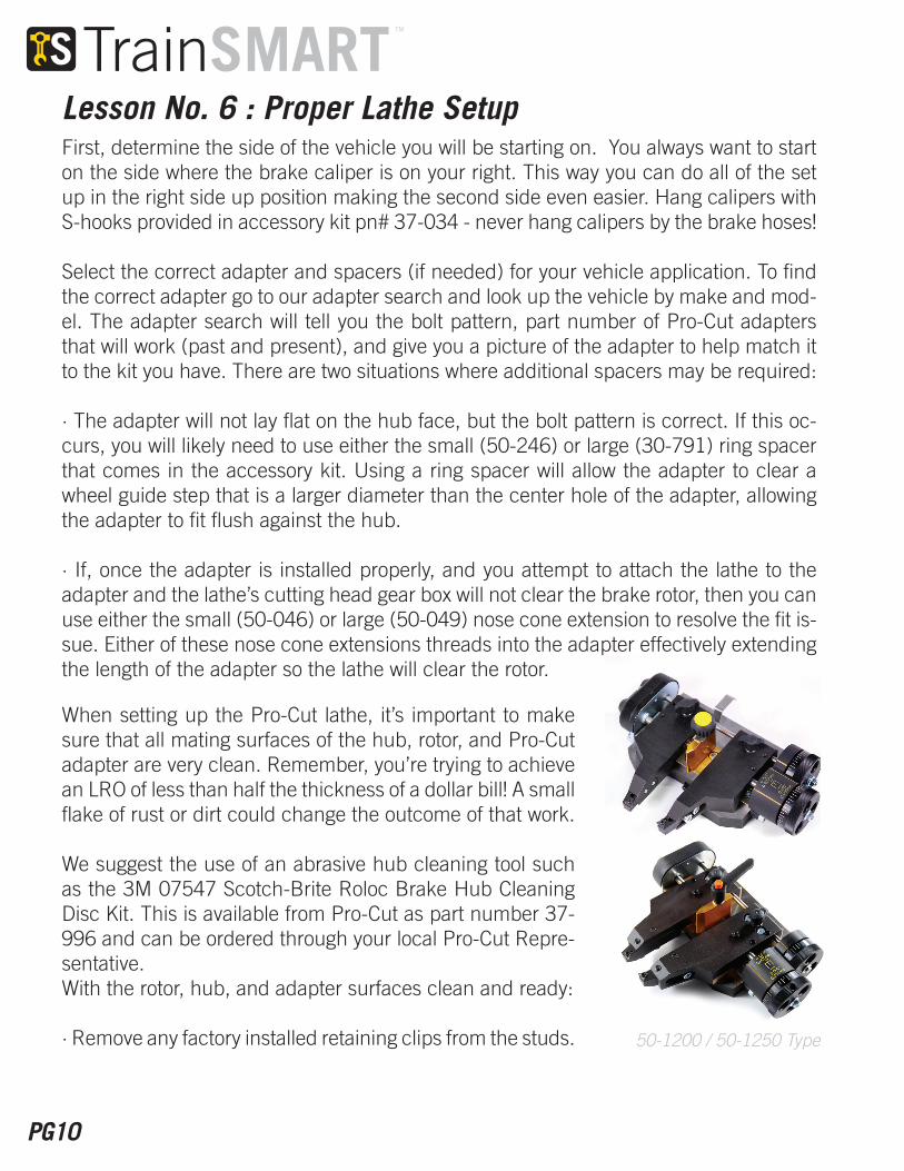
First, determine the side of the vehicle you will be starting on. You always want to start on the side where the brake caliper is on your right. This way you can do all of the set up in the right side up position making the second side even easier. Hang calipers with S-hooks provided in accessory kit pn# 37-034 - never hang calipers by the brake hoses!
Select the correct adapter and spacers (if needed) for your vehicle application. To find the correct adapter go to our adapter search and look up the vehicle by make and mod-el. The adapter search will tell you the bolt pattern, part number of Pro-Cut adapters that will work (past and present), and give you a picture of the adapter to help match it to the kit you have. There are two situations where additional spacers may be required:
· The adapter will not lay flat on the hub face, but the bolt pattern is correct. If this oc-curs, you will likely need to use either the small (50-246) or large (30-791) ring spacer that comes in the accessory kit. Using a ring spacer will allow the adapter to clear a wheel guide step that is a larger diameter than the center hole of the adapter, allowing the adapter to fit flush against the hub.
· If, once the adapter is installed properly, and you attempt to attach the lathe to the adapter and the lathe’s cutting head gear box will not clear the brake rotor, then you can use either the small (50-046) or large (50-049) nose cone extension to resolve the fit is-sue. Either of these nose cone extensions threads into the adapter effectively extending the length of the adapter so the lathe will clear the rotor.
Lesson No. 6 : Proper Lathe Setup
50-1200 / 50-1250 Type
When setting up the Pro-Cut lathe, it’s important to make sure that all mating surfaces of the hub, rotor, and Pro-Cut adapter are very clean. Remember, you’re trying to achieve an LRO of less than half the thickness of a dollar bill! A small flake of rust or dirt could change the outcome of that work.
We suggest the use of an abrasive hub cleaning tool such as the 3M 07547 Scotch-Brite Roloc Brake Hub Cleaning Disc Kit. This is available from Pro-Cut as part number 37-996 and can be ordered through your local Pro-Cut Repre-sentative.With the rotor, hub, and adapter surfaces clean and ready:
· Remove any factory installed retaining clips from the studs.

www.PROCUTUSA.com
When attaching the machine to the adapter, both the face of the adapter and the face of the lathe flange should be flush against each other so there is no space between them. You’ll know you have it right if the draw bar knob spins in freely by hand as an oil filter would.
Due to the self-compensating design of our lathes, the trolley must not be in a bind either on the floor or in either the vertical or camber shock travel range. Put another way, not all the way topped or bottomed out, and not all the way cambered forward or back.
In the event you are having trouble connecting the lathe to the adapter, adjust the height and camber of the lathe by holding the handles on the lathe. Do not try to hold the lathe by the solenoid or any sensitive electronics. The vertical and camber shocks are designed to work with the handles on the lathe to give you the range you need to attach the lathe correctly. If you are outside the range of the trolley, then adjust the lift. Tighten the draw-bar by hand only.
Center the cutting head over the rotor using one of the following methods:Removable cutting head models (50-238): Be certain that the cutting head is pulled squarely into the dovetail before bolting down with a 6mm T-handle provided in the tool kit.Speed-Lock machines (50-220): Slide, center, and lock using lateral lock lever.G2X Cutting heads (50-1200, 50-1250) Slide, center, and lock using lateral lock lever.
Next, mount the adapter and select the best nuts for the appli-cation. Some wheel nuts will not fit well with the Pro-Cut adapt-ers, and you may need to use the nuts provided in either the 50-179 kit that comes with every lathe, or the optional Pro-Cut 50-175 Speed Nut kit.
Lesson No. 6 : Proper Lathe Setup Continued...
For nuts from the vehicle or the 50-179 kit, evenly tighten all nuts in a star pattern by hand to no more than 25-30 ft. lb. Do not use an air operated impact gun! The torque is too high and could damage the adapter.
For nuts provided in the 50-175 Speed Nut kit, use a 12V or less, battery operated, ¼” drive impact gun. Only 12V or less impact guns will provide the correct amount of torque to pro-tect the adapters from damage. Even torque is important and you must tighten in a star pattern!
50-220 Type
50-238 Type

PG12
Center the cutting head over the rotor using one of the following methods:
· Removable cutting head models (50-238): Be certain that the cutting head is pulled squarely into the dovetail before bolting down with a 6mm T-handle provid-ed in the tool kit.
· Speed-Lock machines (50-220): Slide, center, and lock using lateral lock lever.G2X Cutting heads (50-1200, 50-1250) Slide, center, and lock using lateral lock lever.
Next, set up the stop cam by rolling the cutting tips in with the clutch knob to about an 1/8th of an inch from the outer edge of the rotor. Then loosen the thumb screw on the stop cam and slide on the rail until it is just to the left of the stop button on the micro-switch. The automatic shut-off will only work if the stop cam is set up properly. Failure to do so could cause damage to the lathe.
Now index the tips just off the face of the rotor by rolling the cutting head (with the clutch knob) so the cutting tips are over the rotor and wind in the tool arm dial knobs until the cutting tips are just clear of the rotor face.
Now select the correct position rotationally for the cutting process. The correct po-sition is where there are no obstructions that the tool arms will encounter when you wind them in to the start position on the inside edge of the rotor, and where there is enough room to install the correct silencer for that rotor type. Rotate the lathe on the trolley by loosening the disc-lock lever and re-tightening. Do not overtighten.
Start the machine (turn the motor on) and push the START button to compensate the machine for LRO. If for any reason the machine does not show green lights within 60-90 seconds or less, stop and recheck the setup. Newer machines will “time” out automatically after 90 seconds if compensation is not successful.
Lesson No. 6 : Proper Lathe Setup Continued...

www.PROCUTUSA.com
Make sure:
· The adapter fits correctly and the lug nuts are tightened correctly.
· The car is in neutral and traction control is off.
· Any factory retaining clips are removed from the studs.
· The caliper on the opposite side is removed and the rotor is tightened evenly with at least 2 nuts.
· The face of the flange is flush with the face of the adapter.
· The wheels of the trolley are not jammed in any way blocking free motion of the trolley.
· The trolley shock is not all the way topped or bottomed out – there should be some range of motion left in the shock to allow the lathe to compensate freely.
· Emergency brake is disengaged.
Lesson No. 6 : Proper Lathe Setup Continued...

PG14
With the machine compensated for LRO begin the machining process with the scratch cut.
Lesson No. 7 : Machining
Your goal with the scratch is to reference the thinnest part of the rotor, as you will add your cut depth to this point. Measur-ing the rotor with a micrometer should al-ways be part of the job and if you measure from outside to inside in 3 places you will also be able to see if the rotor has taper as well as whether the rotor has enough material left to be machined and still be above minimum specification. Generally you will be removing at least .004” per side, or .008” total from the rotor beyond your scratch depth.
Inspecting the brake pads will also give you an idea whether the rotor may be worn in an irregular fashion and will give you a clue to how much material you may need to remove to complete the job effectively.
If there are gouges in the rotor, use the deepest gouge as the reference point. If there is a buildup of rust, knock off as much as possible before proceeding with the cut.
With the cutting head centered over the rotor and the tool arms separated enough to clear the rotor, wind the cutting head in to about ¼” over the outer edge of the rotor surface and make a light scratch cut on both sides. Start on the inner side of the rotor first and then on the outer side as you can hear the rear scratch but can’t see it. Snug the tool arm lock knob, and zero set the dials so you have a reference point for the rotor face, then loosen the knob and back off the tool arms 4 lines per side (.010”).
Next roll the tool arms to the middle of the rotor and bring the dials back to zero. If the rotor is evenly thick from outside to inside, then your cutting tips will touch the rotor at exactly zero. If that’s not the case and the tips touch the rotor before you hit zero, then the rotor is getting thicker to the inside. If you have to dial the knobs beyond zero, then the rotor is getting thinner to the inside and you should re-set zero at this new thinner scratch reference point. Back off the tool arms and wind them in to 1/8th of an inch from the start point of your cut on the inside of the rotor.

www.PROCUTUSA.com
Repeat the scratch test to see if the cutting tips touch the rotor at zero, if not, es-tablish a new zero reference point and wind the tips in to the starting point paying particular attention to not hitting any obstructions like the hat of the rotor on the outside or the caliper bracket on the inside. Contact between the cutting tips and anything other than the rotor could damage the lathe or the rotor.
Pro-Cut lathes are considered single-pass machines. That means you do not need to first make a rough cut and then a finish like many bench lathes.
There are now two types of cutting tips offered by Pro-Cut: the standard carbide tip (50-742), and the optional polycrystalline cubic boron nitride (or PCBN) cutting tip (50-743). The standard carbide tip (50-742) gives an excellent surface finish that is approved by all OEMs and should last 7-10 cuts per corner when used properly.
The PCBN tip offers even better surface finish results and significantly longer life when used properly. All Pro-Cut lathes use a positive rake cutting tip that works best when used at a cutting depth of no less than .0025” and no more than .020” per side. All of our tips will have 1 dot 2 dot 3 dot corner reference marks. Always start with corner 1 and rotate the two tips in unison. Dots must always be facing up.
It’s important not to be shy with your cut so that you can be efficient with your time. However, if you’ve followed the scratch cut reference procedure properly, you should only ever need to cut at a depth of .004” to .006” per side to accom-plish a superior finish.
Lesson No. 7 : Machining Continued...

PG16
The depth of cut you select is determined by several factors including:
Type of brake rotor
Standard size vented rotor on car or light truck: .004” to .020”
Thin solid rear rotors on cars: .0025” to .0075”
Drilled,Slotted, or dimpled performance rotors: .0025” to .005”
NOTE- See TSB#9 for more info on cutting these rotors
Large medium duty truck rotors when using reach plate: .0025” to .0075”
The amount of DTV
Taper of the rotor
Rust build-up
Gouges in the rotor surface
Lastly and most importantly, the rotors minimum allowable thickness or “machine to” specification must be adhered to!
Lesson No. 7 : Machining Continued
On the Speed Lock cutting head, each line on the knob represents .0025”. There is a stationary refer-ence line for you to use when setting the cut depth. On the G2X cutting head, each line on the knob represents .001”.
Once your depth of cut is dialed in, lock the tool arm lock knob(s) and shut off the machine using either the micro-switch by the cutting head, or the main on/off switch on the electrical box. This is the last chance to double check set up before starting the cut.

www.PROCUTUSA.com
One last time, with the machine off check the following:
· Tool arm lock levers or knobs (depending on model) should be tight
· Cutting head lateral slide lock knob should be tight
· Stop cam is in position
· Check to make sure drawbar is tight
· Depress clutch knob for cutting head feed
· Check disc-lock lever on trolley to make sure it’s snug (do not overtighten)
· Install correct silencer/chip deflector (3 types depending on rotor type)
· 50-703 standard – for regular size vented rotors on cars and small trucks
· 50-754 Solid Rotor style – for thin, solid rear rotors on cars. Has thick blocks and is designed to lay flat on a thin rotor and has 2 position clip to exert additional pressure.
· 50-744 large rotor style – for large cars and trucks up through medium duty. Has thicker wire, heavier spring, and thicker blocks and is designed to lay flat on thicker rotors.
· All silencers/chip deflectors should be installed completely over the rotor with the grooves in the blocks over the cutting tip screw heads and the spring behind the cut-ting head lateral lock lever or knob.
· Position chip tray under the cutting action.
· Start the motor and stand clear of the lathe.
Note: Pro-Cut cutting tips should be the only cutting tips used in the lathe. They cannot be flipped upside down, but can be switched side to side.
Lesson No. 7 : Machining Continued...
PG18
The finished surface, by virtue of the off-center design of the Pro-cut adapter threaded center hole, does not require non-directional finish sanding. The design allows the cutting tips to travel in an orbital motion. This eliminates the tendency that bench lathes have to cut a record groove, or a continuous pattern into the rotor that can cause brake noise.
Lastly, wash and dry your rotors! Use a spray bottle with warm water with a few drops of dish soap and white paper towel!
· Do not use shop rags!
· Do not use Brake Clean!
The smoother the surface, the less potential for a “growl” or other unwanted brake noises! Reduce the chances of a comeback!
Matching the rotor on the second side:
When the cut is complete on the first side and the lathe is shut off by the stop cam, carefully remove the lathe from the vehicle by loosening the drawbar. Use caution as to not crash the cutting tips into any parts of the vehicle as you remove.
Now either install at least two nuts on the rotor you’ve just matched on the first side, or index the rotor to the hub with the crayon from the tool box and remove rotor to make sure it won’t fall on the floor when you start the machine on the opposite side. If you don’t take this step then you will undo the perfect rotor/hub match you just created.
Now rotate the clutch knob counter clockwise, so the stop cam is not in contact with the micro-switch. Next, open both tool arms enough so they will clear the rotor on the second side that has yet to be cut. Remove the adapter and re-install on the second side carefully following all cleaning procedures mentioned previously.
Loosen the disc-lock lever on the trolley and rotate the lathe so the cutting arms will feed in where the caliper was. Attach the lathe and follow all instructions as the same as the first side. The second side should take you even less time as the cutting head and stop cam are already set up.
Lesson No. 8 : Off-Center Design and Second Side Off Center Design
www.PROCUTUSA.com
At this point you have completed two critical tasks:
· Matched the rotor to the hub by taking into account the imperfect nature of the hub and the stacked tolerances from the hub and other components, thereby eliminating a potential pulsation comeback.
· Given the braking surface a new, clean, flat finish that is ready to be mated to the friction material.
Now you must be absolutely certain that you DO NOT jeopardize the fine job you just finished! To complete the job correctly the following MUST be done properly:
· If for any reason you must remove the rotor after completing the match-machin-ing process with the PFM lathe, be sure to match-mark the rotor to the hub with a crayon so you can replace the rotor in that same position. Failure to do this will re-sult in a complete undoing of the LRO correction you just finished! For this reason it’s always preferable to use the PFM last after all other suspension/hub/axle work is compete, and the wheels are ready to go back on the vehicle.
· The lug nuts for the wheels must be torqued to manufacturers’ specifications and in a star pattern order. DO NOT use an impact gun without the proper TorqStik or a torque wrench. Uneven torque will cause the rotor to deflect and will actually induce LRO and cause the undoing of the nearly perfect brake job you just per-formed!
Test drive the vehicle and follow brake pad manufacturer’s recommendations for bed in of new friction material.
Lesson No. 9 : Final Steps

PG20
As with any repair job, you should take pride in what you have accomplished.
Take all the small but necessary steps to return the vehicle to its owner in perfect shape. Make sure you’ve solved the problem that the owner brought the vehicle in for in the first place. And be confident in the work you have just done because your customer is relying on the quality of your service.
Lesson No. 10 : Conclusion & Lathe Maintenance
The Pro-Cut Rotor Matching System is designed to perform exceptionally well, quickly and efficiently. Like any tool, however, it relies on skilled, trained hands and an attentive mind to do its job correctly. That’s where your talents come in!

www.PROCUTUSA.com
