tauhiduzzaman_vedhuis(2014)
TRANSCRIPT

Eg
MM
a
ARRAA
KMTSSSP
1
ptapwAcas
rmaor
0h
Precision Engineering 38 (2014) 481–491
Contents lists available at ScienceDirect
Precision Engineering
jo ur nal ho me p age: www.elsev ier .com/ locate /prec is ion
ffect of material microstructure and tool geometry on surfaceeneration in single point diamond turning
. Tauhiduzzaman, S.C. Veldhuis ∗
cMaster Manufacturing Research Institute, McMaster University, 1280 Main Street West, Hamilton, ON, Canada L8S 4L7
r t i c l e i n f o
rticle history:eceived 17 June 2013eceived in revised form 29 October 2013ccepted 8 January 2014vailable online 21 January 2014
eywords:aterial microstructure
ool nose radiusize effectingle point diamond turning (SPDT)urface roughnessroductivity
a b s t r a c t
There is a strong desire in industry to improve surface finish when performing ultra-precision, singlepoint diamond turning (SPDT) to reduce the amount of post process polishing required to meet finalproduct specifications. However there are well known factors in SPDT which limit achievable surfacefinish. This paper focuses on the role of material microstructure, including grain boundary density andthe presence of inclusions, as well as tool design on surface roughness using the concept of size effect. Sizeeffect can be described as an interplay between the material microstructure dimension and the relativesize of the uncut chip thickness with respect to the cutting edge radius. Since one of the controllableparameters in size effect is grain size and dislocation density, controlled studies were performed onsamples whose microstructure was refined by mechanical strain hardening through rolling and a frictionstir process (FSP). The use of the ultra-fine grained workpiece prepared using an FSP was observed toreduce side flow as well as grain boundary and inclusion induced roughness. The role of tool geometryon material induced roughness was investigated using a tool with a rounded primary cutting edge and
a flat secondary edge. The use of the flat secondary edge was observed to improve surface finish whenmachining a flat surface. This improvement was primarily attributed to a reduction in side flow andmaterial microstructural effects. By combining these approaches an average surface roughness Ra valueof 0.685 nm was achieved when SPDT a flat surface. Furthermore the custom tool has the potential tosignificantly improve the productivity of SPDT by allowing for a much higher feed rate while still achievinga high quality surface finish.. Introduction
Ultra precision, single point diamond turning (SPDT) is a veryromising tool based machining technology which can be used forhe manufacture of computer disks and optical components as wells precision molds [1]. The main feature of SPDT is its ability toroduce high quality surface finishes on the order of nanometershile meeting tight form tolerances on the order of micrometers.chieving a further improvement in surface finish for this pro-ess represents significant value for this industry as it reduces themount of subsequent polishing work that is required to meet finalurface finish requirements.
In a turning operation, the measured peak-to-valley (PV) surfaceoughness usually equals or exceeds the geometrically based esti-ate (Rth) found using f2/(8R�), where f is the feed rate (mm/rev)
nd R� is the tool nose radius. However, below some limiting valuef f, PV is effectively independent of f and may even increase as f iseduced further [2–5].
∗ Corresponding author. Tel.: +1 905 525 9140x27044; fax: +1 905 572 7944.E-mail address: [email protected] (S.C. Veldhuis).
141-6359/$ – see front matter © 2014 Elsevier Inc. All rights reserved.ttp://dx.doi.org/10.1016/j.precisioneng.2014.01.002
© 2014 Elsevier Inc. All rights reserved.
For traditional machining applications Childs et al. [2] observedthe dependency of surface roughness on the workpiece microstruc-ture when machining 0.45% carbon steel. A similar observation forultra-precision machining has been reported by Lucca et al. [6]and Furukawa and Moronuki [7]. They identified material swelling,which is a combination of material side flow, burnishing and elas-tic recovery as a significant contributor to surface finish effects. Fortraditional machining Sata et al. [8] observed that the amount ofswelling is higher for softer and more ductile materials and com-pared this finding to an observation made in an earlier publicationwhen micro turning brass and steel. The primary reason providedin the literature [9,10] for this higher peak to valley roughnesswas material side flow, which is based on the concept of mini-mum chip thickness. This concept states that below a minimumvalue of uncut chip thickness no chip will form but rather materialwill be squeezed out of the cutting zone. This concept was sug-gested by Sokolowski in 1955 [5]; however, the role of materialmicrostructure and tool nose radius at the scale used in ultra-
precision machining, were not considered at that time.Another important aspect of SPDT is the anisotropic natureof the polycrystalline metals, like aluminum, that are typicallymachined. To et al. [11] have shown from their SPDT experiments
4 recisi
twircngt6ieimbwo
S
1234
ItitT[ac
r5s1aoutetwmoaztftidditwrttctraeo
82 M. Tauhiduzzaman, S.C. Veldhuis / P
hat there is a dependency of cutting force and surface roughnessith crystal orientation. Furukawa and Moronuki [7] did some early
nvestigations on polycrystal, single crystal and amorphous mate-ials and concluded that the anisotropy of crystalline materialsannot be neglected in SPDT as they may induce several tens ofanometers of additional surface roughness. They also altered therain size of aluminum alloys by re-crystallizing them at variousemperatures to achieve grain sizes on the order of 160, 270 and20 �m; however, no conclusions were drawn in relation to the
mportance of grain size and its impact on surface roughness. How-ver they did report a strong fluctuation of approximately 2 timesn the cutting forces at the grain boundaries when machining alu-
inum alloys (4% magnesium) leading to the conclusion that grainoundaries have an effect on the cutting force. To date no studiesere found that specifically address the influence of grain boundary
n surface generation in SPDT.As outlined in [12] it is generally agreed that surface finish in
PDT is primarily affected by four factors:
. tool geometry (nose radius, machining parameters),
. relative vibration between tool-workpiece,
. material properties and microstructure and
. tool cutting edge quality.
n the current study the strong influence of material microstruc-ure has been observed over a wide range of feed rates. In additiont has been observed that a small defect in the material microstruc-ure can dominate over other variables in the roughness profile.hus the focus of this article is on relating the relative size effect5] between the cutting mechanism and material microstructurend their impact on surface finish. The role tool geometry plays inombination with workpiece microstructure was also studied.
In SPDT, it is very difficult to further improve the cutting edgeadius (Rˇ) of the diamond tools, which is typically in the range of0 nm [6,7,9,13–15] as well as the positional accuracy and dynamictability of the machine tools, which are already on the order of
nm–10 nm [9,16,17]. However for an oblique SPDT operation with round nose tool the size effect is inevitable due to the variationf the uncut chip thickness along the cutting edge of the tool. Thencut chip thickness varies from a maximum near the middle ofhe chip to effectively zero at the tool tip [18]. Thus, it is appar-nt that the effect of the cutting edge radius dominates near therailing edge of the tool. This is the most critical region as this ishere the final surface is being generated on the workpiece. Duringachining, small material defects in the form of voids, dislocations
r inclusions play a very important role in chip formation due to size dependent effect. When considering the size of the cuttingone for SPDT in comparison to the dominant microstructural fea-ures, the material moving through this critical region can be almostree of material defects. From the theory of plasticity [19] appliedo metal cutting, defects in front of the tool are required to facil-tate plastic deformation and chip formation. With an increase inislocation density, the resistance to dislocation motion by otherislocations becomes more pronounced and results in an increase
n the apparent hardness of the material coupled with a loss of duc-ility [20] in the cutting zone. However, when there is a materialith limited defects, minimal plastic flow is present and the mate-
ial behaves elastically to the point of fracture [5,21]. This implieshat for very small uncut chip thicknesses the material removal is athe atomistic level and thus elastic spring back and plastic side flowan occur. Again, during plastic deformation, it may not be the casehat dislocations traverse grain boundaries during deformation;
ather, a stress concentration ahead of a slip plane in one grain mayctivate sources of new dislocations in an adjacent grain. This mayxplain the observation of Furukawa and Moronuki [7] where theybserved an increase in cutting force at a grain boundary comparedon Engineering 38 (2014) 481–491
to cutting within the grains. While machining Al–Mg alloy with aflat end diamond tool Nishiguchi et al. [22] observed severe tearingon the machined surface at certain orientations and concluded thatthose tears were generated mostly at the grain boundaries.
According to Kishawy and Elbestawi [10] material side flow wasmore pronounced when using a larger nose radius tool in conven-tional machining. This conclusion is in agreement with the studyperformed by Moriwaki [18] on the SPDT of copper. For diamondturning performed with a larger nose radius tool, a greater amountof the chip will have a thickness less than the minimum chip thick-ness needed for cutting. This will lead to an increase in the plowingforce and will lead to increased material side flow. In analyzing thechip morphology, the authors [10] also noticed that an increasein the tool nose radius increased the chip edge serration. In addi-tion, the variation in the chip velocity facilitates the nonuniformdisplacement along the chip width and, hence, further promoteschip edge serration. Chip edge serration indicates that some part ofthe material is being left behind on the machined surface and willbecome a signature of side flow on the freshly machined surfaceand so increase the roughness of the surface. However, no workhas been found outlining the effect of tool geometry on side flowin SPDT.
The main objective of this study is to understand the relation-ship between material microstructure and cutting tool geometryon surface finish during SPDT. This knowledge could be used toreduce the post processing required to meet the tight surface fin-ish values needed for some high end applications. In this study99.87% aluminum was mechanically strain hardened to refine themicrostructure and to increase the dislocation density. This wasdone by rolling the material to reduce its thickness and in addi-tion to this technique an ultra-fine grain structure was producedon the surface of the workpiece using a friction stir process (FSP).SPDT experiments were also performed with different tool geome-tries in an effort to better understand the relationship between toolgeometry and material microstructure and their impact on surfacefinish. A new tool design has been proposed with a flat secondaryedge that restricts side flow in the direction of the final surfacebehind the tool by avoiding chip thinning in this region. These tworefinements are combined and their impact on surface finish is alsooutlined.
2. Experimental setup
The experiments were conducted on a multi axis Precitech 700Gultra precision machine tool. Single crystal diamond tools wereused to perform a face turning operation and the tool was pos-itioned on the rotary axis placed on top of a linear axis to providefeed. The tools had a cutting nose radius of 1.50 and 0.50 mm. A spe-cially designed tool which combined a 0.50 mm nose radius witha 0.50 mm long flat secondary region was also tested. To get thebest outcome from the flat end tool, it is important to keep the flatend of the tool parallel to the workpiece. This was achieved in twosteps with the help of the rotary axis on the machine, which hasa positional accuracy of 0.0001◦. In step 1, a plunge cut (groove)is made on a carefully mounted and machined rotating workpiece.The groove was then measured using a Zygo Newview 5000 whitelight interferometer (WLI) to estimate the angle of tilt of the flatedge of the tool with respect to the flat workpiece surface. This mea-sured value was then used to adjust the rotary axis of the machineto align the flat of the tool to the workpiece surface. In step 2, cuts
were made on the workpiece at a higher feedrate (30 �m/rev) andagain the resulting surface was measured using a WLI to fine tunethe angle of the flat section of the tool. Step 2 was repeated untilthe desired alignment was achieved.
M. Tauhiduzzaman, S.C. Veldhuis / Precision Engineering 38 (2014) 481–491 483
Table 1Cutting parameters.
Workpieces (99.87% aluminum) Cutting tools (diamond) RPM Depth of cut (�m) Feed rate (�m/rev)
I. Furnace cooled (23HV) I. 1.5 mm nose radius 1000 2 50, 20, 10, 5, 3, 1, 0.8,0.6, 0.4 and 0.2
II. 54% strain hardened (29HV) II. 0.5 mm nose radiusm
afwcAveuDdcsSooiotsoacCt
3
rt
12
3
wTt
TC
a 1.5 mm nose radius tool. This comparison was done to showthat material side flow dominates when the material is not strain
III. 82% strain hardened (54HV) III. 0.5 mm nose radius and 0.5 msecondary flat edge
IV. Ultrafine grained structure (78HV)
Furnace cooled and strain hardened 99.87% pure aluminumnd ultra-fine grained 99.87% aluminum samples, prepared by ariction stir process, were used as workpiece materials. All theorkpieces were 100 mm in diameter and mounted on a vacuum
huck using a dial indicator to keep the eccentricity within ±1 �m. WLI was used to measure the surface roughness. All roughnessalues reported were completed at 400× magnification with a lat-ral resolution of 0.56 �m with no filtering. Vegetable oil mist wassed for lubrication and to aid chip removal from the cutting zone.ifferent combinations of tool and workpiece were studied underifferent feed rates with surface roughness values reported. Theutting parameters and workpiece materials used in this study arehown in Table 1. Chips were collected and then observed under acanning Electron Microscope (SEM). Tool condition was assessedptically under 800× magnification after each pass to ensure nobservable wear was present on the rake face and then observedn a SEM at the end of the study to ensure no tool wear or stickingf aluminum was observable on the cutting edge. Table 2 showshe chemical composition of the aluminum workpiece used in thistudy. Ultra-fine grains were produced using a friction stir processn a Fadal CNC milling machine at 400 RPM, 68 mm/min feed ratend 3.05 mm depth of penetration with chilled air directed at theontact zone. Micro hardness data was collected using a CLEMEXMT 5.0 micro-indentation tester at 25 gf load with 10 s of dwellime and the values are reported in Table 1.
. Results and discussion
The issue of side flow, anisotropy and grain boundary inducedoughness during surface generation is addressed in this study fromwo fundamental directions for the SPDT process:
. Workpiece material considerations and
. Tool geometry considerations
.1. Workpiece material considerations
Initially, a furnace cooled 99.87% aluminum alloy was turnedith a 1.5 mm nose radius diamond tool at different feed rates.
he measured surface roughness value was observed to be higherhan the theoretical predicted value based on the equation: f2/(8Rε).
able 2hemical composition of 99.87% aluminum alloy.
Element Composition (%)
Aluminum 99.8746Chromium 0.00029Copper 0.01102Iron 0.0418Magnesium –Manganese –Nickel 0.00109Silicon 0.00756Strontium (Sr) 0.00294Tin (Sn) 0.01307Titanium 0.00493Zinc 0.0427
Fig. 1. Surface finish defects (feed 20 �m/rev, Furnace cooled 99.87% Al. 1.5 mm R�).
Preliminary analysis performed using SEM images of the surface,typical example shown in Fig. 1, determined that this is primarilydue to plastic side flow, as well as grain boundary and materialinclusion induced roughness.
Initial efforts were made to reduce the surface roughness byengineering the original furnace cooled material by strain harden-ing using cold rolling to achieve a 54% reduction in thickness. Thiswas done to increase the number of active slip planes by increasingthe dislocation density in the material. Machining results showedthat strain hardening improved the surface roughness by reduc-ing the peak to valley roughness primarily by reducing plastic sideflow and spring back (swelling effect). This can be seen in Fig. 2,which shows the measured peak to valley (PV) height and super-imposed simulated surface profile (Rth) for a 20 �m feed rate using
hardened. A relatively high feed rate of 20 �m was used to aidin resolving the individual feed marks on the WLI. This observed
Fig. 2. Comparison of surface finish (WLI data).

484 M. Tauhiduzzaman, S.C. Veldhuis / Precision Engineering 38 (2014) 481–491
nd d)
icpmm
iwh
Fig. 3. Chip investigation: edge serration (a and b) and back free surface (c a
mprovement in PV roughness was attributed to the higher dislo-ation density associated with the strain hardening process. Thisrocess results in an increased material hardness which makes theaterial prone to fracture as opposed to plastically deform whenachined.
Chip edge serration is also a sign of material side flow or plow-ng. Fig. 3(a) shows that edge serration was increased when theorkpiece was not strain hardened as compared to the 54% strainardened alloy. This is shown in Fig. 3(b) near the trailing edge
Fig. 4. Effect of grain boundary and inclusion in surface generation (wo
comparison for furnace cooled and 54% cold rolled 99.87% aluminum alloys.
of the tool. This is because the material at the trailing edge of thetool is subjected to high stress that causes tearing of the weakestsection of the chip [10,21]. However, strain hardening introducesdislocations and a high density of dislocations reduces the serra-tion of the chip and allows the material to fracture. In this case
the generated surface was closer to the value predicted by the toolgeometry alone. In machining operations, the back or free surfaceof the chips shows a lamella structure which is a sign of a shear-ing process taking place. The deck of card model is based on thisrkpiece: furnace cooled 99.87% aluminum; 1.5 mm R�; 5 �m/rev).
recisi
owaFs
baepdtariotpftf
M. Tauhiduzzaman, S.C. Veldhuis / P
bservation [5]. However, the spacing between active slip planesas higher in chips collected from the furnace cooled aluminum
lloy than the strain hardened aluminum alloy as can be seen inig. 3(c) and (d) respectively suggesting that there were more activelip planes when the material was strain hardened.
Moreover, the furnace cooled aluminum shows strong grainoundary induced roughness as compared to a strain hardenedlloy at lower feed rates. This is primarily because a strain hard-ned alloy has a higher dislocation density that acts as a source oflastic deformation in the adjacent grain in the cutting and feedirection. Fig. 4(a) shows that the surface roughness generated byhe grain boundary while machining a furnace cooled aluminumlloy at 5 �m/rev feed rate is approximately 30 nm. This is rep-esented by line 2 in Fig. 4(b). It has also been observed that thenclusions that are inherent in the alloy can generate the formationf dimples on the surface and a localized surface roughness fea-ure that dominates over all the other factors described up to this
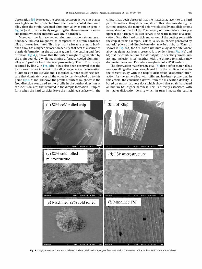
oint. Fig. 4(c) and (d) shows the profile of surface roughness in theeed direction compared to the profile in the cutting direction athe inclusion sites that resulted in the dimple formation. Dimplesorm when the hard particles leave the machined surface with theFig. 5. Chips, microstructure and machined surface produced at 1 �m/rev
on Engineering 38 (2014) 481–491 485
chips. It has been observed that the material adjacent to the hardparticles in the cutting direction pile up. This is because during thecutting process, the material deforms plastically and dislocationsmove ahead of the tool tip. The density of these dislocations pileup near the hard particle as it serves to seize the motion of a dislo-cation. Once this hard particle moves out of the cutting zone withthe chip, it forms a dimple. Peak-to-valley roughness generated bymaterial pile-up and dimple formation may be as high as 75 nm asshown in Fig. 4(d) for a 99.87% aluminum alloy at the site wherealloying elemental iron is present. It is evident from Fig. 4(b) and(d) that the combinations of material pile up near the grain bound-ary and inclusion sites together with the dimple formation maydominate the overall PV surface roughness of a SPDT surface.
The observation made by Sata et al. [8] that a softer material hasmore swelling effect can be explained from the results obtained inthe present study with the help of dislocation–dislocation inter-action for the same alloy with different hardness properties. In
this article, the conclusion drawn from the dislocation density isbased on micro hardness data which shows that strain hardenedaluminum has higher hardness. This is directly associated withits higher dislocation density which in turn impacts the cuttingfeed rate with 1.5 mm nose radius tool for 99.87% aluminum alloys.

486 M. Tauhiduzzaman, S.C. Veldhuis / Precision Engineering 38 (2014) 481–491
ptc
tAimo9itwpttsrsmtwna[asetbimebsdtaeaww
h
TE
Fig. 6. Effect of tool nose radius on chip thinning.
rocess. Thus, strain hardening improves surface finish by changinghe flow of the material through the cutting zone both promotingutting and reducing side flow.
It has been observed that further refining of the grain struc-ure takes place under the severe stress associated with machining.
clear observation of sub-grain formation during strain harden-ng and refinement of sub-grains [23] has been observed after
achining. There is also a measurable increase in micro hardnessn the machined surface. Micro hardness of 54% strain hardened9.87% aluminum is 29HV while the hardness in the surface region
ncreases to 36HV after it is machined. This increase is attributedo the micro extrusion process that occurs during machininghere a thin layer of the machined surface undergoes severelastic deformation because of the size effect and organizes itselfhrough further grain refinement. This observation has promptedhe authors to look for processes which further refine the graintructure of the workpiece. The objective for this further grainefinement was to bring the material microstructure into a refinedtate before machining to realize the enhancement observed afteraking a first pass. Thus furnace cooled 99.87% aluminum was fur-
her strain hardened by a thickness reduction of 82%. The resultsill be discussed in the next section. In addition to further rolling,ew techniques for grain refinement of bulk materials have beendopted by Valiev et al., using severe plastic deformation processes24–26]. However, nanostructured materials have found limitedpplication as a result of the high cost of preparation and themall achievable dimensions of the final product [27]. Recently Sut al., reported that the friction stir process (FSP) can be adoptedo produce bulk ultra-fine grains [27,28]. In this study the FSP haseen developed by adapting the friction stir welding process. FSP
s a thermo-mechanical process, which is typically performed on ailling machine [29] and according to Rajeswari [30], FSP param-
ters play a vital role in defining the resulting grain size. It haseen observed that a lower rotational speed and a higher travelingpeed have the potential to further reduce the grain size. Thus, nineifferent single pass combinations of RPM, feed and depth of pene-ration were tried before reaching a FSP condition which produced
surface with low void formation and ultra-fine grains. These twofforts are correlated with the chip morphology shown in Fig. 5(a)nd (b). These figures indicate a reduction of chip edge serration
ith a percentage increase of strain hardening. This is in agreementith the previous observation made regarding Fig. 3(a) and (b).However, the microstructure shown in Fig. 5(c) for an 82% strainardened sample of 99.87% pure aluminum indicates an increased
able 3ffective maximum uncut chip thickness under which surface generates.
Feed rate (�m) 1.5 mm nose radius (nm) 0.5 mm nose radius (nm)
20 266 80210 67 201
5 16.5 503 6 181 0.7 20.8 0.4 1.280.6 0.24 0.720.4 0.12 0.320.2 0.02 0.08
Fig. 7. Effect of material microstructure and tool geometry on surface quality.
intensity of micro porosity in the form of voids generated throughexcessive plastic deformation. This micro porosity was found tonegatively impact the surface generation and thus did not providea better surface finish. This is attributed to the inherent defectsinduced by the severe mechanical strain hardening process. Ithas been observed that micro fractures that are present on themachined surface are the underlying cause of the deterioration inthe surface finish in this case. Fig. 5(e) shows a micro scaled voidproduced from the machining operation on the 82% strain hard-ened alloy. It is believed that the material failed by ductile tearingthrough void formation and coalescence due to the stress generatedby the cutting process. This phenomenon of ductile tearing has been
introduced by Subbiah [31] while doing experiments on aluminumto validate Atkins [32] model for metal cutting. This suggests that ahigh degree of strain hardening may not be suitable to improve sur-face finish, even though it may improve aspects of machinability.
M. Tauhiduzzaman, S.C. Veldhuis / Precision Engineering 38 (2014) 481–491 487
arden
Cmcwntfiviwaot
3
r
Fig. 8. Chip produced from 54% strain h
onversely, Fig. 5(d) shows the ultra-fine grained 99.87% pure alu-inum microstructure produced by FSP. Under these processing
onditions FSP produced a surface layer which is almost defect freeith an average grain size of less than 1 �m. It is interesting toote from Fig. 5(f) that with bulk grain refinement resulting fromhe use of the FSP, side flow is completely eliminated and 1 �meed marks are visible under high magnification SEM when machin-ng under specific RPM conditions [33] which serve to isolate theibration induced tool overlaps typically seen when SPDT. Interest-ngly the 1 �m feed marks are not visible for any other workpieces
hen using the same cutting parameters and techniques. This isttributed to the lack of side flow which promotes the diffractionf light from the surface and leads to a rainbow like appearance onhe surface of the part.
.2. Engineering the cutting tool
It is well understood from the kinematic equation of surfaceoughness that with an increase in tool nose radius, the peak to
ed alloy with different tool geometries.
valley surface roughness will decrease. This statement is generallyvalid up to a point. It has been observed that nose radius does nothave any significant influence on surface roughness below somelimiting value of feed rate. The measured PV value deviates morefrom the theoretical roughness value (Rth) as the tool nose radiusincreases [34]. The limiting value depends on nose radius, feed rate,workpiece material properties and relative tool workpiece vibra-tion. Considering only the material properties, it has been observedthat surface roughness may even become higher with a larger noseradius tool. When using a larger nose radius, severe chip thinningtakes place as opposed to when a smaller nose radius tool is used.The impact this has when using a round nose tool is schematicallyshown in Fig. 6 for a 1.5 and 0.5 mm nose radius tools for 20 �mnominal depth and a 20 �m/min feed rate. The schematic is drawnto scale and a magnified view of the cutting zone is highlighted.This analysis is an extension of the results shown in Table 3 where
effective geometric uncut chip thickness under which surface isgenerating is tabulated for 1.5 and 0.5 mm nose radius tool for 2 �mnominal depth of cut for different feed rates.
488 M. Tauhiduzzaman, S.C. Veldhuis / Precision Engineering 38 (2014) 481–491
bs90smatFpaostiTsnaotwnitb
fcF21cia
s1eToubtcca
0
50
100
150
200
250
300
0.1 1 10 100
Rou
gh
nes
s (n
m)
Feed rate (µ m/rev)
Furnace co oled 99.87 % al uminum
0
50
100
150
200
250
300
0.1 1 10 100
Rou
ghnes
s (n
m)
Feed rate (µ m/rev)
54% co ld rol led 99.87% alu minum
PV (1.5mm Rε)
PV (0.5mm Rε)
Rth (0.5mm Rε)
Rth (1.5mm Rε)
PV (0.5 mm Flat and Rε)
(a)
PV (1.5m m Rε)
PV (0.5mm Rε)
Rth (0.5mm Rε)
Rth (1.5mm Rε)PV (0.5 mm Flat and Rε)
(b)
0
50
100
150
200
250
300
0.1 1 10 100
Rou
ghnes
s (n
m)
Feed rate (µ m/rev)
FSP 99.8 7% alumin um
PV (1.5mm Rε)
PV (0.5mm Rε)
Rth (0.5mm Rε)
Rth (1 .5mm Rε)PV (0.5mm Flat an d Rε)
(c)
Fig. 9. Summary of tool geometries.
Fig. 7 provides a comparison of optical surface finish qualityased on low magnification (0.5×; scale: 5 mm) optical micro-copic images of the machined surfaces of furnace cooled and FSP9.87% aluminum alloys. Machining was done with 1.5 mm and.5 mm nose radius tool at a feed rate of 50 �m/rev. Fig. 7(a) clearlyhows the anisotropic nature of the furnace cooled 99.87% alu-inum alloy when machined with a 0.5 mm nose radius tool. This
nisotropic appearance is not present in Fig. 7(b) and (c) wherehe microstructure and tool geometry was changed respectively.ig. 7(b) represents a surface generated with the same cuttingarameters; however, the workpiece is the ultra-fine grained FSPluminum sample. By comparing Fig. 7(a) with Fig. 7(b) one canbserve that the grain refinement and increase in dislocation den-ity changes the cutting physics in SPDT due to the size effect andhe material starts behaving as a bulk material due to the closenessn size between the cutting edge and the material microstructure.he reason the anisotropy is not visible in the furnace cooled alloyhown in Fig. 7(c) is due to the chip thinning effect, as a largerose radius (1.5 mm) tool is used in this case. This observation is ingreement with the observation made by Moriwaki [18] where hebserved that during orthogonal flycutting at a higher uncut chiphickness, the surface integrity is influenced by crystal orientation;hich however, have minimum effect at smaller uncut chip thick-ess. In oblique cutting with a larger nose radius tool, this influence
s reduced due to more chip thinning near the trailing edge of theool. This reduces the effective uncut chip thickness and results inetter surface quality.
However, severe chip thinning results in more side flow at lowereed rates as material entering into the smaller thin section of thehip will have less stress concentrating defects to produce the chip.ig. 8(a) and (b) shows chips produced from two different tools at0 �m/rev feed rate and Fig. 8(c) and (d) shows chips produced at
�m/rev feed rate from the 54% strain hardened alloy. It can be con-luded from Fig. 8(a–d) that a larger nose radius tool always resultsn more edge serration of the chip and edge serration increases with
reduction in feed rate.This was considered when designing the special tool with the
econdary flat edge. Previously used flat end tools had a length of.2 mm and a pointed corner and were primarily used to study theffect of orientation angle between the tool and workpiece [35].he motivation of the current work was to address the side flowf the material at the trailing edge of the tool. The idea was tose the flat edge of the tool to close off the area for material toe squeezed and so avoid side flow. The flat secondary edge of the
ool has a 0.5 mm length to provide sufficient tool material at theutting edge to have the strength needed at the tool tip to supportutting loads. Cutting edges of all the three tools used in this studyre shown superimposed on one another in Fig. 9. The theoreticalFig. 10. Comparison of PV and Rth roughness values for tool geometries andmicrostructures of 99.87% aluminum alloys.
surface roughness with this custom tool in fact is 0 nm, until thefeed rate exceeds the length of the flat secondary edge of the toolwhich is 500 �m in this case. Remaining roughness is then dueto tool alignment issues and vibration. The nature of the contactbetween the flat section of the tool and the workpiece also couldprovide extra process damping which would serve to reduce thevibration induced roughness component of the surface finish. Thedynamic response of the flat edge tool is currently under furtherinvestigation. Fig. 8(e) shows the chip produced using a flat endtool on a 54% strain hardened aluminum alloy. It can be seen fromFig. 8(e) that the flat end tool is capable of producing an excep-tionally smooth chip surface which corresponds to the smoothworkpiece surface produced.
3.3. Combined effect of material microstructure and toolgeometry
Peak to valley roughness graphs (semi-log) are shown inFig. 10(a–c) for the furnace cooled, 54% strain hardened and FSPaluminum samples respectively for different tool geometries andfeed rates. As expected, the flat end tool gives the best surface

recisi
ritbitnawr
theem(eo
at
M. Tauhiduzzaman, S.C. Veldhuis / P
oughness for all of the combinations. It is interesting to note thatn the case of the furnace cooled alloy, roughness is higher withhe larger round nose radius tool which contradicts the predictionsased on the kinematically based trend as shown in Fig. 10(a) but
s consistent with the chip thinning effects discussed earlier. Inhe case of the 54% strain hardened aluminum alloy, both roundose tools show similar performance. Finally, in the case of the FSPlloy, the roughness pattern matches the kinematically based trendhere a larger round nose radius tool produces a better surface
oughness.It is worth mentioning that the flat end tool not only improves
he surface finish, but also the productivity by allowing for muchigher feed rates. For example the roughness achieved with the flatnd tool at 20 �m/rev cannot be achieved with a round nosed toolven at 0.2 �m/rev. From this study it has been observed that theinimum average surface roughness achieved was Ra: 0.685 nm
PV: 3.955 nm) using a combination of the FSP alloy and the flatnd tool at 0.4 �m/rev. Fig. 11(a) shows the WLI generated image
f the surface.Material anisotropy was not observable in the case of the FSPlloy because of the relative size of the grains and the uncut chiphickness so the FSP material behaved like a bulk isotropic material.
Fig. 11. Effect of microstructure in surface generation
on Engineering 38 (2014) 481–491 489
Moreover, the FSP resulted in the absence of large grain boundariesand related defects as shown in Fig. 5(d). Strain hardening due torolling does refine the grains and promote sub-grain formation;however, the elongated grains still remain in the microstructure.In this case tearing marks are observed at the grain boundarieson the larger grained alloys while machining with the flat endtool. It has been observed in Fig. 4 that the round nose toolcaused material to pileup at the grain boundary. For the case ofthe flat end tool the trailing edge of the tool was able to addressthe pile up of material and effectively remove it. Because of theanisotropic nature of the material, the tool cannot always cut thematerial. Instead, the material comes out as a torn section thatgenerates irregularities on the surface. Such tearing at the grainboundaries are prominent in soft alloys as shown in Fig. 11(c)and less with the cold rolled sample shown in Fig. 11(d) and notobservable for the FSP sample shown in Fig. 11(b) and (e). Sim-ilar observations were made by other researchers [35]. The WLIintensity map in Fig. 11(a) and SEM image in Fig. 11(e) with labels
showing grain size show the FSP surface machined with the flatend tool showing no visible defects optically at 400× which isshown in Fig. 11(b) and at 7500× with an SEM image shown inFig. 11(e).with flat end tool on 99.87% aluminum alloys.

4 recisi
4
tmsrctmtrcdwmeocAofsetbasdrsnt5fihfrtiwitaasTHwtaamsiaui
sTtante
[
[
[
[
[
[
[
[
[
[
[York: John Wiley & Sons, Inc.; 1997.
[21] Shaw MC. Precision finishing. CIRP Ann Manuf Technol 1995;44(1):343–8.
90 M. Tauhiduzzaman, S.C. Veldhuis / P
. Conclusions
In this study, effort has been made to understand and improvehe achievable surface roughness by engineering the workpiece
aterial and the geometry of the diamond cutting tool. Our analysishowed that under a wide range of machining conditions mate-ial side flow, grain boundaries and inclusions can be significantontributors to a poor surface finish. Thus, the main objective ofhis study was to understand the relationship between workpiece
aterial microstructure and the role of the cutting tool geome-ry on material side flow, grain boundary and inclusion inducedoughness in the SPDT process. Enhancing surface finish is of criti-al importance for reducing the cost and improving the quality ofiamond turned components. Dislocation density of the materialas found to impact side flow by facilitating the fracture of theaterial during chip formation. In the SPDT operation, strain hard-
ning and ultra-fine grain refinement using a FSP was performedn 99.87% pure aluminum alloy to facilitate chip formation and wasompared with the surface produced on the furnace cooled alloy.
series of mechanical, optical and cutting tests were performedn all the workpiece materials and chips. Cutting tests were per-ormed with round nosed tools (1.5 and 0.5 mm nose radius) and apecially designed flat end tool (0.5 mm nose radius and 0.5 mm flatnd) was tested while changing the feed rate from 20 �m/rev downo 0.2 �m/rev. Material side flow induced roughness was reducedy strain hardening. Chip edge serration at the trailing edge was
minimum with the strain hardened alloy. This was taken as aign of enhanced machinability that could be related to the higherislocation density associated with the cold rolled and FSP mate-ials. Again, grain boundary and inclusions induced roughness wasevere and was the determinant factor for overall surface rough-ess in the furnace cooled alloy when machined with a round noseool. The round nose tool gives promising surface roughness with4% strain hardened aluminum alloy followed by the FSP ultra-ne grained aluminum alloy; however, the use of the 82% strainardened alloy produced voids, fractures and pitting in the final sur-
ace so that the furnace cooled alloy produced the poorest surfaceoughness. Plowing was entirely eliminated when machining withhe FSP alloy and is attributed to its high dislocation densities andts ultra-fine grain structure. Because of this reason, rainbow colors
ere observed even at 1 �m feed rate due to the diffraction of lightnduced by the periodic nature of the machining grooves. In regardo the tool geometry, it has been observed that nose radius playsn important role at lower feed rates. Irrespective of the feed rates,
larger nose radius tool produces poorer surface roughness than amaller nose radius tool when machining the furnace cooled alloy.his is attributed to chip thinning and its associated size effects.owever, roughness is comparable for different round nose toolshile machining a 54% strain hardened alloy. Cutting tests showed
hat chip thinning and the size effect were reduced when machiningn ultra-fine grained alloy and the larger nose radius tool produced
better surface roughness, which is in agreement with the kine-atic surface roughness prediction. In a test run of 50 �m feed rate,
evere deterioration of surface quality was observed when machin-ng the furnace cooled alloy with a 0.5 mm nose radius tool. This wasttributed to the size effect. Surface quality was then improved bysing an ultra-fine grained material prepared by a FSP and then by
ncreasing the tool nose geometry.Based on the above observations, a tool was designed with a
harp nose radius and a flat secondary edge to eliminate side flow.he specially designed tool provided the best surface finish for allhe cases studied. However, some tearing at the grain boundary
long the cutting direction was observed while machining the fur-ace cooled and the 54% strain hardened alloy with the flat edgeool. This is believed to be due to the successive passes of the flatnd over the hard grain boundaries. Defects generating from the[
[
on Engineering 38 (2014) 481–491
grain boundaries while using the flat end tool were completelyeliminated when the ultra-fine grained alloy was used. Average sur-face roughness (Ra) values of less than 1.0 nm have been repeatedlyproduced without any visible defects using this combination of cus-tom tool and specially prepared workpiece across a range of feedrates. Moreover, the flat end tool was found to effectively increasethe productivity substantially when generating a planar surface.Finally, the best surface finish generated in this study has an averagesurface roughness: 0.685 nm (peak-to-valley roughness: 3.955 nm)on a friction stirred ultra-fine structured 99.87% aluminum using adiamond tool with a flat secondary cutting edge.
Acknowledgments
The authors would like to thank the Natural Sciences and Engi-neering Research Council of Canada (NSERC), the Ontario Centers ofExcellence (OCE) and B-Con Engineering for their financial supportof this research.
References
[1] G. Chapman. Ultra-Precision Machining Systems: An Enabling Technologyfor Perfect Surfaces, Moore Nanotechnology Systems LLC, Winchester Street,Keene, NH 03431, USA. Available: http://www.nanotechsys.com/technology/
[2] Childs THC, Dornfeld D, Lee D-E, Min S, Sekiya K, Tezuka R, Yamane Y. Theinfluence of cutting edge sharpness on surface finish in facing with round nosedcutting tools. CIRP J Manuf Sci Technol 2008;1(2):70–5.
[3] Childs THC, Sekiya K, Tezuka R, Yamane Y, Dornfeld D, Lee D-E, Min S, WrightPK. Surface finishes from turning and facing with round nosed tools. CIRP AnnManuf Technol 2008;57(1):89–92.
[4] Liu K, Melkote SN. Effect of plastic side flow on surface roughness in micro-turning process. Int J Mach Tools Manuf 2006;46(14):1778–85.
[5] Shaw MC. Metal cutting principles. New York: Oxford University Press; 2005.[6] Lucca DA, Seo YW, Rhorer RL, Donaldson RR. Aspects of surface gener-
ation in orthogonal ultraprecision machining. CIRP Ann Manuf Technol1994;43(1):43–6.
[7] Furukawa Y, Moronuki N. Effect of material properties on ultra precise cuttingprocesses. CIRP Ann Manuf Technol 1988;37(1):113–6.
[8] Sata T, Li M, Takata S, Hiraoka H, Li CQ, Xing XZ, Xiao XG. Analysis of surfaceroughness generation in turning operation and its applications. CIRP Ann ManufTechnol 1985;34(1):473–6.
[9] Dornfeld D, Min S, Takeuchi Y. Recent advances in mechanical micromachining.CIRP Ann Manuf Technol 2006;55(2):745–68.
10] Kishawy HA, Elbestawi MA. Effects of process parameters on material side flowduring hard turning. Int J Mach Tools Manuf 1999;39(7):1017–30.
11] To S, Lee WB, Chan CY. Ultraprecision diamond turning of aluminium singlecrystals. J Mater Process Technol 1997;63(1–3):157–62.
12] Sohn A, Lamonds L, Garrard K. Modeling of vibration in single-point diamondturning. In: Proceedings of the ASPE, American Society for Precision Engineer-ing, 21st annual meeting. 2006.
13] Ng CK, Melkote SN, Rahman M, Senthil Kumar A. Experimental study ofmicro- and nano-scale cutting of aluminum 7075-T6. Int J Mach Tools Manuf2006;46(9):929–36.
14] Liu X, Devor RE, Kapoor SG, Ehmann KF. The mechanics of machining at themicroscale: assessment of the current state of the science. J Manuf Sci Eng2004;126(4):666.
15] Chan KC, Cheung CF, Ramesh MV, Lee WB, To S. A theoretical and experimentalinvestigation of surface generation in diamond turning of an Al6061/SiCp metalmatrix composite. Int J Mech Sci 2001;43(9):2047–68.
16] Byrne G, Dornfeld D, Denkena B. Advancing cutting technology. CIRP Ann ManufTechnol 2003;52(2):483–507.
17] Corbett J, McKeown PA, Peggs GN, Whatmore R. Nanotechnology: inter-national developments and emerging products. CIRP Ann Manuf Technol2000;49(2):523–45.
18] Moriwaki T. Machinability of copper in ultra-precision micro diamond cutting.CIRP Ann Manuf Technol 1989;38(1):115–8.
19] Gurson AL. Continuum theory of ductile rupture by void nucleation andgrowth: Part I – Yield criteria and flow rules for porous ductile media. TransASME 1977;99:2–15. Available at: http://imechanica.org/files/Gurson’smodelASME.pdf
20] William J, Callister D. Materials science and engineering an introduction. New
22] Nishiguchi T, Maeda Y, Masuda M, Sawa M, Uehara K. Mechanism of microchip formation in diamond turning of Al–Mg alloy. CIRP Ann Manuf Technol1988;37(1):117–20.
23] Sedlácek R, Blum W, Kratochvíl J, Forest S. Subgrain formation during deforma-tion: physical origin and consequence. Metall Mater Trans 2002;33A:319.

recisi
[
[
[
[
[
[
[[[
[
M. Tauhiduzzaman, S.C. Veldhuis / P
24] Valiev R. Nanostructuring of metals by severe plastic deformation for advancedproperties. Nat Mater 2004;3:511–6.
25] Valiev RZ, Alexandrov IV. Nanostructured materials from severe plastic defor-mation. Nanostruct Mater 1999;12(1–4):35–40.
26] Valiev RZ. Bulk nanostructured materials from severe plastic deformation. ProgMater Sci 2000;45(2):103.
27] Su JQ. A new route to bulk nanocrystalline materials. J Mater Res2003;18(8):1758.
28] Su J-Q, Nelson TW, Sterling CJ. Grain refinement of aluminum alloys by frictionstir processing. Philos Mag 2006;86(1):1–24.
29] Mishra RS, Mahoney MW, McFadden SX, Mara NA, Mukherjee AK. High strainrate superplasticity in a friction stir processed 7075 Al alloy. Scr Mater2000;42:163–8.
[
[
on Engineering 38 (2014) 481–491 491
30] Itharaju RR (Thesis) Friction stir processing of aluminum alloys; 2004.31] Subbiah S (Thesis) Some investigations of scaling effects in micro-cutting; 2006.32] Atkins AG. Modelling metal cutting using modern ductile fracture mechan-
ics: quantitative explanations for some longstanding problems. Int J Mech Sci2003;45(2):373–96.
33] Meyer PA, Veldhuis SC, Elbestawi MA. Predicting the effect of vibration on ultra-precision machining surface finish as described by surface finish lobes. Int JMach Tools Manuf 2009;49(15):1165–74.
34] Sugano T, Takeuchi K, Yoshida Y. Diamond turning of an aluminum alloy formirror. Ann CIRP 1987;36(1):17–20.
35] Masuda M, Maeda Y, Nishiguchi T, Sawa M, Ikawa N. A study on diamond tur-ning of Al–Mg alloy – generation mechanism of surface machined with worntool. CIRP Ann Manuf Technol 1989;38(1):111–4.