tate oard s p o n a u ust s - · pdf file3 lined trench as secondary containment for piping 6...
TRANSCRIPT

STATE WATER RESOURCES CONTROL BOARD’SPANEL ON THE
LEAK HISTORY OF NEW AND UPGRADED USTSYSTEMS
UPGRADED UST RELEASE SITE EVALUATION CASE STUDIES
(UST Team 2 Report)
JANUARY 1999
PARTICIPATING TEAM 2 MEMBERS
Mr. Dave Camille - Tosco Marketing CompanyMr. Cris Hamilton - County of Sacramento Environmental Management Department
Mr. Jim Jones - South Lake Tahoe Public Utility DistrictMr. Chris Steck - City of Mountain View, Fire Department
Ms. Cris Tulloch - Santa Clara Valley Water DistrictMr. Steve Welge - Fillner Construction
Mr. Chris Winsor - ARCO Products
CALIFORNIA STATE WATER RESOURCES CONTROL BO A R D
Mr. Allan Patton, Advisory Panel ChairpersonMs. Shahla Farahnak, P.E., Project Lead and UST Workgroup Chairperson
Ms. Mary Drewry, Project Assistant

Upgraded UST Release Site Evaluation Case Studies
2/16/99
TABLE OF CONTENTS
I. EXECUTIVE SUMMARY 3
II. BACKGROUND 4
III. FINDINGS AND RECOMMENDATIONS 5
Findings 51 All Tanks 52 Sumps 53 Lined Trench as Secondary Containment for Piping 64 Secondarily Contained Piping 65 Single Wall Piping 66 Dispenser Area 77 Leak Detection 78 Installation 79 Enforcement 7
Recommendations 71 All Tanks 72 Sumps 73 Line Trenches as Secondary Containment for Piping 84 Secondarily Contained Piping 85 Single Wall Piping 86 Dispenser Area 87 Leak Detection 88 Installation 89 Enforcement 8
APPENDIX I 9
APPENDIX II 44

Upgraded UST Release Site Evaluation Case Studies
2/16/99 3
I. EXECUTIVE SUMMARYThe Upgraded UST Release Site Evaluation Case Studies Team’s task was to evaluateupgraded UST sites where Methyl tertiary Butyl Ether (MTBE) was present in thesubsurface, for the purpose of determining site specific factors resulting in a release ofMTBE. Local Oversight Program and Implementing Agency files for approximately 26sites were reviewed and 22 of these sites were visited. Upon investigation of specificfacilities, most releases appear to be fuel system leaks. Some of the apparent causes ofleaks are faulty installations, poor maintenance, upgrades that do not fully comply withthe regulatory requirements and poor facility operation practices. Very few sites showevidence of MTBE contamination only. Therefore, it is unlikely that MTBE is escapingfuel systems without a general leak in the system. In a few cases MTBE was the onlyconstituent found. This may be due to the physical properties of MTBE; it is watersoluble and does not easily adhere to soil particles. Other gasoline constituents, on theother hand, are not generally water soluble, adhere strongly to soil particles, and degradeeasily in an oxygen rich environment. As a result, MTBE may move more rapidly andfarther from the leak source, and be detected in monitoring wells ahead of other gasolineconstituents.
Improvements in management of UST programs are needed. Detailed and regularinspections of current UST systems by qualified agency or third party inspectors couldresult in the identification of some of these problems and enable correction of thedeficiencies. More intense scrutiny of installations by qualified regulators or qualifiedthird party inspectors would increase the probability that UST systems are properlyinstalled. Stricter guidelines to insure installation contractors are properly qualified toinstall UST systems could decrease the incidence of improperly installed systems.Existing State requirements are inadequate because they do not ensure that installationpersonnel have been trained for specific products. Many manufacturers, primarily tankand piping manufacturers, offer training in the proper installation of their products. Localregulatory agencies should verify that installation personnel have been properly trained inthe product manufacturer specifications prior to installation of the system.
The UST regulations appear to be adequate for the design and construction of newsystems. However, the requirements for upgrading existing systems, may allow for lesseffective systems to remain in use. A properly maintained and operated fully doublewalled or secondarily contained system is less likely to allow a release into theenvironment than a single wall system.
The scope of work for this team was limited to review of UST release sites where MTBEand other gasoline constituents were detected. No budget was allocated for the projectand no actual testing was conducted by the team. The sample population used to conductthis survey of upgraded and new tanks was heavily biased because only facilities whichexperienced a prior release were addressed. As a result, at many of the sites it was notpossible to determine if the release was from a previously removed system or the existingsystem which meets the 1998 upgrade requirements. Based on this fact alone the teamrecommends that an evaluation be conducted of UST systems on sites that have not
Upgraded UST Release Site Evaluation Case Studies
2/16/99 4
experienced a prior leak. This new study would reduce the amount of unknowns at a siteand thus give a more objective view of the UST system.
II. BACKGROUNDThe task of this team was to confirm or deny the ability of UST systems, that arecompliant with the 1998 deadline requirements, to adequately contain the product theyare storing, oxygenated fuel, and more specifically, to look at each component of thesystem and assess if it is functioning as designed, as installed, and as operated.
In general, there are three types of UST systems that comply with the regulations asmeeting the 1998 deadline standards: double wall systems, single wall systems, andhybrid systems, the latter being a combination of the first two. A double wall system is anew system installed after July 1, 1987 and is comprised of a secondarily containedtank(s) and secondarily contained piping. Currently, some new systems upgraded orinstalled prior to 1995 do not include secondary containment for the dispenser area.Trench lined product piping systems that were used early on, around 1985 to 1989, alsofit into the double walled category. Double walled systems are monitored with sensorsthat detect liquid or vapor that has collected in the interstitial space between the primaryand secondary containment of the tank and piping. A sensor is also required in thedispenser pan. Single wall systems were typically installed prior to 1984 and have asingle wall tank(s) with single wall piping. A single wall system storing petroleum that isconstructed of fiberglass reinforced plastic (FRP) meets the 1998 standards with theaddition of striker plates, a spill container, and an overfill prevention device. However, asingle wall steel tank storing a petroleum product will need replacement or require liningor an internal bladder and cathodic protection, along with the previously mentionedupgrades for FRP tanks. A typical single walled tank system with pressurized lines ismonitored by a combination of the following: Automatic Tank Gauge (ATG) orStatistical Inventory Reconciliation (SIR) and an Electronic Line Leak Detector (ELLD)with the capability of shutting down the turbine if a leak of 3 gph is detected or thesystem malfunctions or is disconnected. In addition, monthly (0.2 gph) and annual (0.1gph) piping integrity tests must be performed. A hybrid system, installed between 1984and July 1, 1987, consists of a double wall tank(s) with single wall piping. The tank ismonitored with a sensor that detects liquid or vapor that has collected in the interstitialspace between the primary and secondary containment of the tank. The single wallpressurized piping is monitored with an ELLD as described above.
The following approach and general considerations were used to evaluate the USTsystem included in the study:
1. UST systems included for possible consideration met the 1998 upgrade regulationsand had a history of MTBE detected at the site. These were identified in variousways, by local agencies that implement the UST program, volunteers working on thepanel, utility districts, and other public entities. A few of the sites evaluated came
Upgraded UST Release Site Evaluation Case Studies
2/16/99 5
from investigations initiated following the discovery of releases while installingelectrical upgrades.
2. The evaluation included reviewing case files and visiting sites to attempt to identifyspecific problems associated with the UST system.
3. The sites were already being monitored for MTBE and other gasoline constituentswhich allowed members to establish contaminant trends over time. An increasingconcentration suggested a possible release. However, review of this data could notalways provide a definitive answer to whether the release was due to the new USTsystem or an old UST system previously removed from the site.
4. Once a potential site was selected, the local agency was contacted and asked toprovide information relating to the design, installation, and operation of the USTsystem. The file information was evaluated for 1998 deadline compliance, evidenceof an ongoing release, and other possible problems that might indicate the system wasleaking or had leaked.
5. If the results of the evaluation met the upgrade and MTBE detection criteria then asite inspection was conducted to verify the UST system components and, if possible,identify leak sources.
III. Findings and RecommendationsDesign, installation, and operation/maintenance of the UST system components wereinvestigated and evaluated. For the purpose of this report, the findings have beensummarized under the specific system components or activity where weaknesses orproblems were identified.
Findings
1 All TanksDue to the lack of an allocated budget for testing or unearthing of tanks, the team had nomeans to identify leaks associated with the secondary containment of double wall tanks.However, a Lower Explosive Limit (LEL) meter was used to test the annular space of sixUSTs. Of these six USTs, three were found to have a high reading of flammable vapors.
2 SumpsTurbine sumps were visually inspected at each facility (13 sites had sumps installed) andwere identified as one of the potential problem areas of double wall UST systems. Thepurpose of the turbine sump is to capture leakage from the primary piping carried to thesump, by way of gravity, via the secondary containment piping or from the turbine itself.If the sump is not liquid tight the product can be released into the environment and not bedetected by the monitoring system. Another problem resulting from leaking sumps iswater intrusion. At six sites (# 1, 5, 7,13, 15, 23) sumps were observed to contain waterand/or product. Build up of water in sumps is another complication that leads to falsealarms and bypassing or disabling of monitoring systems. Five sites (#1, 7, 13, 15, 23)were observed to have the probes pulled up because of water intrusion. If the monitoringsystem is not properly operated, leaks from primary piping or turbines may go

Upgraded UST Release Site Evaluation Case Studies
2/16/99 6
undetected. Therefore, proper installation, maintenance and monitoring of the sumps iscrucial to the containment and detection of leaks. Out of 13 sites that required sumps,nine sites ( #1, 3, 5, 6, 7, 8, 10, 18, 23) were identified as having sumps which wereimproperly installed. Of these nine sites, five (#3, 7, 8, 10, 23) had penetration fittingswere either improperly installed or completely missing. Current installation guidelinesrequire sumps to be inspected during installation. There are no requirements to testsumps after the initial testing. The fact that nine of the systems were not properlyconnected may result from lack of proper installation inspection (i.e., the sump may havenever been tested to see that it was liquid tight). Another possibility is that damage orfailure may have occurred some time after the initial installation and testing.
3 Lined Trench as Secondary Containment for PipingThe integrity and design of secondary containment for piping systems with lined trenchesare not easily evaluated because the end points of the liner are difficult to locate withoutremoving surface features. Testing usually consists of filling the liner with water orremoving surface features, and performing a visual inspection. Of the three sites wheretrench liners were known to exist, two (#8, 10) were improperly designed/installed andtwo sites (#10, 11) were improperly monitored. If a leak develops in the primary pipingit may not be detected if the trench liner is improperly designed, monitored or leakingitself. Additionally, water intrusion into a trench system at one site (#11) causednuisance problems that may have resulted in bypassing the monitoring system, similar toproblems with turbine sumps.
4 Secondarily Contained PipingDue to the lack of an allocated budget for testing or unearthing of UST systems, the teamhad no means to identify leaks associated with the secondary containment of double wallpiping. Fourteen sites were identified as having integral secondarily contained piping.One system which was reviewed and visited (site #3) utilized non-fiberglass secondarypiping (i.e., non bonded systems connections) utilizing hose clamp connections whichmay not remain liquid tight. In addition, several members of the team have beeninvolved with inspecting sites where similar materials and method of construction havebeen used. This knowledge coupled with the team’s work has prompted a concern for theability of systems with hose clamp connections to remain liquid tight after installation.
5 Single Wall PipingThe team visited four single wall systems. Single wall fiberglass piping was found joinedwith steel unions (sites #17, 18) and some piping systems were put together withinadequate epoxy (site #18) and in one case (site #17) silicon caulking was used insteadof epoxy. Evidence was found that piping systems were installed with epoxies that werenot compatible with the piping material (sites #17, 18, 22). Additionally, gaskets withinflexible connectors where found to leak when allowed to dry out prior to being placedback into service (site #3). A majority of all single wall systems were installed prior to1984. At this time most communities did not have programs for regulating USTs. As aresult, standards for installation of these systems and inspections for their constructionand tightness may have been non-existent or inadequate.

Upgraded UST Release Site Evaluation Case Studies
2/16/99 7
6 Dispenser AreaTen sites were observed to have dispenser area secondary containment (dispenser pans).Connections beneath dispensers were found to be leaking at 12 facilities. At 6 of thesefacilities (sites # 6, 7, 8, 10, 11, 22) the leaks were directly discharged to the environmentdue to the lack of dispenser containment. At 6 facilities (sites # 3, 4, 5, 9, 16, 19, 23)dispenser containment was adequate to contain the release. Dispenser pans are a part ofthe secondary containment requirements for new UST facilities (after 1987). However,due to problems with interpretation of this requirement, many systems were installed orupgraded prior to August of 1995 without dispenser containment. After 1995clarification was issued by the State Board which stated that all new systems must installdispenser containment. In addition, the Board has given guidance suggesting that localagencies require facilities to install dispenser containment, for those not already incompliance, anytime concrete is broken in the area. As a result, a portion of the “new”UST population has not yet installed dispenser pans.
7 Leak DetectionFor the leaking single wall piping systems discussed above (site # 17, 18, 22), the leakdetection method or the integrity test used did not detect the leak. This was evidenced bythe contamination found along the piping run. A possible answer for this problem maybe that the leak threshold of the on-site monitoring equipment or third party testingequipment is not capable of detecting a very small release. Over time even a very smallleak can contribute to an environmental problem. Improper operation or maintenance ofthe monitoring systems and disabling or ignoring alarms may also result in leaks goingundetected (site #3).
8 InstallationMany of the problems with the UST systems appear to be a result of improper installationor poor maintenance. Many of the problems found with the UST systems may have beendiscovered during a thorough installation inspection, by either a local agency or a thirdparty (sites #1, 3, 7, 10, 11, 17, 22, 23).
9 EnforcementIn some circumstances, local agency inspections had identified deficiencies in monitoringissues such as line and tank testing, but follow-up enforcement did not occur.
Recommendations
1 All TanksFurther appropriately funded study is needed to evaluate the integrity/compatibility ofdouble walled tanks.
2 SumpsState regulations/guidance for proper installation and periodic inspection of sumps shouldbe developed.

Upgraded UST Release Site Evaluation Case Studies
2/16/99 8
3 Line Trenches as Secondary Containment for PipingRequire that all secondary trench lined systems be properly maintained, monitored andperiodically tested for tightness.
4 Secondarily Contained PipingRequire that all secondary containment systems, regardless of type, be properlymaintained, monitored, and periodically tested for tightness.
5 Single Wall PipingAll single wall systems should be investigated to ensure that they were properly installed.
6 Dispenser AreaDevelop a phase-in approach to ensure dispenser containment is properly installed,maintained and periodically inspected at all facilities. The phase-in approach may takeinto account site specific risk factors.
7 Leak DetectionDevelop better testing methodologies for single wall piping systems. If bettermethodologies cannot be developed or utilized, all single wall piping systems should beevaluated for replacement using a phase-in approach that may take into account sitespecific risk factors. Stricter enforcement of monitoring system regulations may helpinsure monitoring systems are properly operated and maintained.
8 InstallationEnsure that all UST systems are properly inspected during installation by trainedinspectors and regularly maintained by trained and qualified owners and operators. Inaddition, UST facilities should be inspected during all phases of installation and atregularly intervals during operation.
9 EnforcementEnsure that non-compliance is followed by appropriate enforcement. Ensure that localagencies have a mechanism in place to cite, fine, or otherwise easily enforce compliancerequirements.

Upgraded UST Release Site Evaluation Case Studies Site Summaries
2/16/99 9
Appendix I
Site Summaries

Upgraded UST Release Site Evaluation Case Studies Site Summaries
2/16/99 10
Lead Agency: County of El DoradoSite Address: South Lake Tahoe, CA
Existing UST System Components:System type: PressureTanks: Double wall FRP Owens Corning (2@10,000) installed 9/28/85Piping: Double wall flex, Total Containment, Enviroflex installed in 5/93Dispenser Containment: yes, Total Containment deep boxesSump: yes, Total ContainmentSpill: Yes, OPWOverfill: Yes, OPW SO61 drop tubeStriker Plate: yesVapor Recovery: Stage I - coaxial, Stage II - balance
Compliance Monitoring:• Upgrades were done in 1993 by Fillner. At this time sumps and dispenser containment was installed
although there are no sensors in the dispenser pans.• Tidel EMS-3000 for interstitial monitoring tanks and sumps.• There is a copy of a tank test in the file but it was done on 9/5/97. This was before the two consecutive
fails.• Although it is not required for a double wall tank, they are also using SIR, Simmons, and failed the
months of 12/97 , 1/98, and 2/98. There is a tank test by ProTank on 4/3/98 that gave the system apass for both the tank and the piping.
• Monitor certification form completed on 9/5/98 verified that there are 3 interstitial monitors.• There are Red Jacket and Vaporless MLLD on the piping.• No monitoring plan is available for the facility
Site Visit: (10/5/98)
• This site does not have any visual evidence of leaks.• No sensors were found in the dispenser containment.• Turbine sump were dirty but had no visual evidence of leaking.
Site Investigation:• Soil sampling was done at the site in 1993 when the sumps and dispenser pans were installed. No
Detect was the result for all the analytes.• No Unauthorized Release Form for this site to date.• On June 18, 1998 a Notice to Submit Workplan for Site Investigation was issued by the Regional
Board. This action was initiated when 377 ppb MTBE was found in a monitoring well up gradient tothe site at a former Rotten Robbie station. This site had always been ND for MTBE and the facilityhad just recently reported a release based on a fail on their SIR (dates above).
• A report will be sent to the Regional Board by October 1, 1998 that identifies probable leaks.
Action:The report by Fluor Daniel GTI (9/28/98) found some MTBE and very low levels of Benzene at 0.384 ppband THPg at 31 ppb in the soil. In the ground water higher levels of MTBE at 212 ppb, Benzene at 170ppb and THPg at 2.1 ppb were detected. The report suggests that a further study of the site be conducted.
Conclusions:• This site meets the 1998 deadline standards.• The team had no means of evaluating the tanks at this site.• From the site investigation there were no visible signs of a release from the current system.• The agency might consider requiring turbine shutdown at this facility since compliance for piping
integrity testing seems to be an enforcement issue.

Upgraded UST Release Site Evaluation Case Studies Site Summaries
2/16/99 11
Lead Agency: County of El Dorado, Regional Water Quality Control Board, R6,South Tahoe Public Utility District
Site Address: Meyers, CA 95501
Existing UST System Components:System type: PressureTanks: Double wall steel FPR clad tanks. 2 (compartmentalized) @ 20,000 Joor - installed on 7/24/96Piping: primary piping fiberglass-Ameron, secondary containment Total Containment-blue HDPE puttogether with clamps.Dispenser Containment: yes, Bravo Box with floatsSump: yes, Western FiberglassSpill: yes, type unknownOverfill: Yes, mechanical float valve in fill tubeStriker Plate: yesVapor Recovery: type unknown
Compliance Monitoring:• EBW Auto Stick is being used to monitor the interstitial space and the turbine sumps.• Red Jacket LLD, XLP• Repairs are reported to have been done to the regular piping without permit from the local agency.• No monitoring plan is available for the facility• No piping integrity tests were available for the site although the piping system does not have shutdown
a 3 gph leak. Site Visit (8/11/98)
• At the time of the team visit the monitoring system was found to be turned off at the breaker and whenturned back on was not functional. Therefore, the team was unable to verify the components of themonitoring system. The system is listed as having automatic shut off.
• Both the premium and the diesel were not dispensing product (paper bags over the nozzles).• The diesel dispenser pan had both product and water in it and the float switch in the box had not
triggered the shear valve. Upon inspection with a flashlight we could see that product was leakingfrom the dispenser piping above the shear valve.
• The was no key available for the other dispensers, the key had broken off in the lock.• The turbine sumps were inspected and the premium sump had a mixture of water and product.
Apparently there is a leak in the primary piping. The sensor was pulled up so that the alarm would notgo off.
• There was no significant amount of liquid present in the regular turbine sump. This may be due to asuspected leak in the secondary piping.
Site Investigation:• There was also a complaint filed about dumping of product at the site on (3/15/94)• There are two Unauthorized Release Forms (UFR) for this site. The first was for the tank removal
(7/26/96) and the second was a leaking diesel pump on the old system (2/16/96)• A leak was detected by the monitoring equipment and confirmed by a piping tightness test. It was
found to be a Flextite flex connection under the dispenser pan on the regular unleaded line. Thesecondary containment was not tested during investigation of the leak and not tested after the leak wasrepaired.
• Product in the sump was detected after the repairs had been made. The lines were tested again and aleak in the secondary containment was found in addition to a leak in the unleaded plus line.
• We have copies from a on site investigation but it provides no date. GPT-1-14 at 2,800ppb, GPT-21-22 at 3,900ppb, GPT-29-22 at 3,500ppb (these are the highest readings)
• Lahontan Regional Board is currently in charge of remediation that had been implemented in order tocontain the plume.
Upgraded UST Release Site Evaluation Case Studies Site Summaries
2/16/99 12
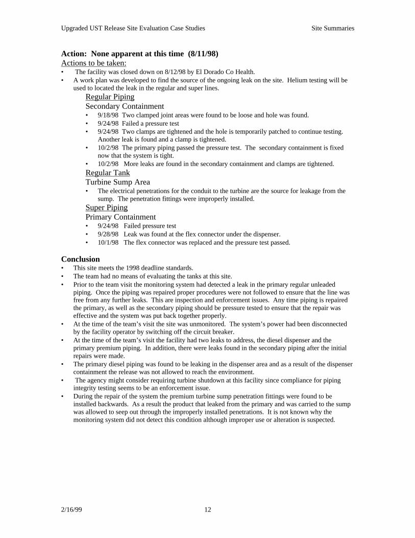
Action: None apparent at this time (8/11/98) Actions to be taken:
• The facility was closed down on 8/12/98 by El Dorado Co Health.• A work plan was developed to find the source of the ongoing leak on the site. Helium testing will be
used to located the leak in the regular and super lines.Regular PipingSecondary Containment• 9/18/98 Two clamped joint areas were found to be loose and hole was found.• 9/24/98 Failed a pressure test• 9/24/98 Two clamps are tightened and the hole is temporarily patched to continue testing.
Another leak is found and a clamp is tightened.• 10/2/98 The primary piping passed the pressure test. The secondary containment is fixed
now that the system is tight.• 10/2/98 More leaks are found in the secondary containment and clamps are tightened.Regular TankTurbine Sump Area• The electrical penetrations for the conduit to the turbine are the source for leakage from the
sump. The penetration fittings were improperly installed.Super PipingPrimary Containment• 9/24/98 Failed pressure test• 9/28/98 Leak was found at the flex connector under the dispenser.• 10/1/98 The flex connector was replaced and the pressure test passed.
Conclusion• This site meets the 1998 deadline standards.• The team had no means of evaluating the tanks at this site.• Prior to the team visit the monitoring system had detected a leak in the primary regular unleaded
piping. Once the piping was repaired proper procedures were not followed to ensure that the line wasfree from any further leaks. This are inspection and enforcement issues. Any time piping is repairedthe primary, as well as the secondary piping should be pressure tested to ensure that the repair waseffective and the system was put back together properly.
• At the time of the team’s visit the site was unmonitored. The system’s power had been disconnectedby the facility operator by switching off the circuit breaker.
• At the time of the team’s visit the facility had two leaks to address, the diesel dispenser and theprimary premium piping. In addition, there were leaks found in the secondary piping after the initialrepairs were made.
• The primary diesel piping was found to be leaking in the dispenser area and as a result of the dispensercontainment the release was not allowed to reach the environment.
• The agency might consider requiring turbine shutdown at this facility since compliance for pipingintegrity testing seems to be an enforcement issue.
• During the repair of the system the premium turbine sump penetration fittings were found to beinstalled backwards. As a result the product that leaked from the primary and was carried to the sumpwas allowed to seep out through the improperly installed penetrations. It is not known why themonitoring system did not detect this condition although improper use or alteration is suspected.

Upgraded UST Release Site Evaluation Case Studies Site Summaries
2/16/99 13
Lead Agency: County of El DoradoSite Address: Meyers, CA
Existing UST System Components:System type: PressureTanks: Double wall FRP 3 @ 10,000 & 1 @ 6,000 installed on 10/20/90. XerxesPiping: Double wall FRP was installed in 1990 and again in 10/96. At this time it is not know why therelatively new piping needed to be replaced.Dispenser Containment: Yes, Western Fiberglass, deep box, with Beaudreaus installed in 10/96 when thesecond round of DW FRP went in 1996.Sump: Yes, Western Fiberglass, FRPSpill: Yes, OPW, 2100, 5 gallonOverfill: Yes, OPW 61SO drop tube and a ball float valve.Striker Plate: YesVapor Recovery: coaxial
Compliance Monitoring:• Facility Inspection report filled out for 7/2/97 and 8/11/98.• No monitoring plan is available for the facility• An EBW Autostick sensor is used to monitor the interstitial space and the turbine sump for the piping.
(There are currently no sensors in the dispenser pans and this deficiency was noted on the inspectionreport on 8/11/98).
• The inspection sheet indicates that the sump sensors are not programmed to perform shutdown for thepump in the event of a release yet there have been no annual piping tightness tests submitted since theinstall in 1990. There was no indication of a piping tightness test done when the new DW piping andthe dispenser pans were installed.
Site Visit: 10/1/98• The facility has excellent housekeeping practices except for their diesel dispenser used by the public
agencies.• Beaudreau sensors have been installed in the dispenser pans.• The dispenser pans were clean and dry although the piping under most of the dispenser (Wayne
dispensers) was visibly wet. This may have been where the leaking originated prior to the installationof the dispenser pans.
• All the turbine sumps were clean, dry and the sensors were working.• There is no visible evidence of a leak at this site.
Site Investigation:• MTBE found in the municipal wells in the are prompted the investigation. Site investigation found
MTBE in the ground water below the site.• An Unauthorized Release Form was file in 1998 but release was supposedly from old tanks found at
closure, 4 SW steel tar wrapped. The date on leak discovered is 9/12/90. The analysis at the time ofremoval did not detect any gasoline constituents only diesel and oil & grease.
• A new Unauthorized Release Form was submitted stating that the old tanks must have leaked whenthere was no apparent investigation into the new tank system. No sampling was done, in order toconfirm this assumption, when the dispenser pans were installed. Sampling might have picked up thecontamination that currently existed.
• In 1998 GP1 MTBE - soil 4-6’ 180 ppb and 14-16’ 18 ppb 2/18/98 near the pump islands.• In 1998 GP3 MTBE - soil 14-16’ 71 ppb 60’ north of GP3.
Action:Installation of dispenser pan sensors is in progress.
Upgraded UST Release Site Evaluation Case Studies Site Summaries
2/16/99 14
Conclusions:• This site meets the 1998 deadline standards.• The team had no means of evaluating the tanks at this site.• The agency might consider requiring turbine shutdown at this facility since compliance for piping
integrity testing seems to be an enforcement issue.• From the site investigation there were no visible signs of a release from the current system.• It is believed that the high levels of MTBE may have come from the dispenser piping prior to the
installation of dispenser containment.
Upgraded UST Release Site Evaluation Case Studies Site Summaries
2/16/99 15
Lead Agency: El Dorado CoSite Address: South Lake Tahoe, CA
Existing UST System Components:System type: PressureTanks: Double wall steel clad FRP compartmentalized 12,000/8,000, installed on 10/15/96, ModernWeldingPiping: Double wall flexible installed on 10/15/96, EnviroflexDispenser Containment: yes, Western FiberglassSump: yes, Total ContainmentSpill: yes, Emco Wheaton 6 gallonOverfill: Yes, OPW 61SO drop tubeStriker Plate: yesVapor Recovery: Healy
Compliance Monitoring:• No monitoring plan available for the facility, Interstitial monitor Incon TS1000 EFI is listed.• Tank tightness testing by Tanknology NDE Vacutest on 8/23/97• Piping tightness testing by Tanknnology on 8/23/97• Install sheet says that the system has auto shutdown for the turbines.• No inspection since installation in 10/96• No annual maintenance of monitoring equipment• Vaporless LD2000 MLLD in use.• A report from TerraVac on July 20, 1998 gives details on the status of the UST system. This report
suggests that the system was improperly installed and not properly maintained and operated.• The report states:
♦ The dispenser pans contained 25 to 40 gallons of water and sludge. Piping penetrations maybe the culprit here.♦ The piping does not flow back towards the piping sump.♦ One of the dispenser pans was grossly deformed. The product-pipe test collars were still inplace and tightly fastened, showed deterioration, and were improperly installed.♦ Levels of MTBE in the liquid sampled from the turbine sumps and dispenser pans are asfollows: M-1 and 2 are 23,000 and 22,000 respectively and D-1 through 5/6 are 11,000, 35,000,89,000, and 44,000 respectively.♦ The vapor system would not pass initial testing and was repaired.♦ Maintenance records could not be located at the site.♦ The current filters are not dated and maintenance records could not be located by the stationattendant. Filter changing records were not available.
Site Visit (10/5/98)• This site has experienced problems associated with high ground water.
• Housekeeping practices at this facility were not good.• The Enviroflex piping was joined together with clear small plastic tubing connecting the pipe
interstices in the dispenser pans only. The secondary was open in the turbine sumps (at the tanks).Any leaks in the primary pipe should flow back to the turbine sumps. The liquid would accumulate inthe turbine sumps until the liquid sensor detected the liquid, and set off the alarm.
• Liquid (a mix of water and fuel or only water) was visible in sumps and the sensors had been pulled upso that the alarm would not go off.
• To verify that the alarm was functional it was placed in the liquid in the bottom of the sump and it didgo off with a visual and audible alarm. Neither of the turbines were running so it was not possible, atthat time, to tell if the system had shutdown for the turbine.
• The dispenser pans were not equipped with sensors.

Upgraded UST Release Site Evaluation Case Studies Site Summaries
2/16/99 16
• The dispenser pan and piping looked as if it had leaked in the past. There was a build up of debris inthe bottom of the pan that appeared to have been wet a some point.
Site Investigation:• Tanks were removed on 9/9/91 and it is not clear why there were no tanks at the site from 1991 until
1996.• UFR was filled out in 1991 due to the tank closure.• MTBE was first discovered on the site from sampling analysis in February 1997.• The most current monitoring results are from 12/97 and describe injecting diluted 10% hydrogen
peroxide into the wells and the reduction of MTBE as a result.• On June 26, 1998 the Regional Board issued a Notice to Immediately Conduct Remedial Activities at
the site. A work plan was requested to describe the actions employed to determine if the dispensers arepotential leak sources.
Action:none other than listed above
Conclusions:• This site meets 1998 deadline standards.• The team had no means of evaluating the tanks at this site.• There is no information in the files to suggest that any work has been done on this system since the
7/20/98 evaluation by TerraVac.• This site has in the past and was, at the time of the team visit, bypassing the monitoring system by
elevating the sensors in the turbine sumps. This is an enforcement issue.• In the turbine sumps, the piping and the turbine should be considered potential leak sources and
evaluated as such.• The dispenser area should be investigated as a potential leak source.

Upgraded UST Release Site Evaluation Case Studies Site Summaries
2/16/99 17
Lead Agency: El Dorado CoSite Address: South Lake Tahoe, CA
Existing UST System Components:System type: PressureTanks: Double wall steel clad with FRP, 1@ 10,000 and 1@ 8,000 installed on 9/89, TruscoPiping: Double wall FRP installed on 10/89, AO Smith (see comments under site visit below).Dispenser Containment: noneSump: yes, FRP with no penetration fittings only caulk. The cover for the sump is the wrong size.Spill: yes, found to be defective but replaced on 8/14/98Overfill: Yes, OPWStriker Plate: yesVapor Recovery:
Compliance Monitoring:• No Monitoring plan in the file, Interstitial monitor Universal, Leak Alert• Contract upgrade progress report for 8/12,13,14/98
• Report suggests that the double wall piping does not currently terminate in the sump.• The sumps will be lake tested.• Overfill will be replaced.• Spill buckets will be replaced.• Shutdown of the sump sensor could not be confirmed by the contractor.• Contractor was to check the monitoring system.• Install fill sumps.
• From the inspection on 5/29/98 the alarms were not operating (turned off or not functional?) Theprobes in the turbine sumps were disconnected.
• A tank and piping test was performed by Champion on 5/8/98, Pass
Site Visit 10/1/98• Very bad housekeeping practices at this facility.• The installation is also a source of problems.
The Sump• The piping, at the time of the visit, terminates in the turbine sump. This may have been a major
source of leakage if there were or are any piping problems.• There are no penetration fittings on the sumps and caulking is used to seal the penetrations.• At the time of the re-inspection the sumps were said to have held water.• The sump covers are the wrong size.• The electrical conduit has been sealed with caulk and as a result of an incorrectly screwed on
....and the box is full of water.• Dispensers have no pans. In all four dispensers it is impossible to tell by visual inspection whether the
system is DW. In one dispenser there is a boot visible but it is still impossible to see the secondarycontainment.
• One dispenser was leaking product, the piping was wet and the ground stained.• The cement around the dispensers was stained and look as if the hoses may have leaked. The staining
may be due to the carelessness of the person filling the vehicle’s tank and spilling fuel on thepavement.
• The monitoring system was functioning although there is no turbine shutdown, no ELLD, and noevidence of annual piping tests.
• The spill containment and the overfill protection devices have been fixed and appear to be in workingorder.
Site Investigation:

Upgraded UST Release Site Evaluation Case Studies Site Summaries
2/16/99 18
• UFR was reported on 11/30/89 as a loose fitting detected at the tank closure.• UFR was reported on 1/31/97 as an unknown source discovered by subsurface monitoring.• MTBE was first discovered on the site from sampling analysis in 3/25/96.• On June 15, 1997 a Cleanup and Abatement Order was issued as a result of MTBE contaminating
wells in the area. The facility owner/operator was to conduct quarterly monitoring, identify the causeof the gasoline constituents in the ground water, stop the release, define the plume, and implement acorrective action plan to clean up the area.
• The problem was found to be a defective overfill device and spill bucket. There may have beenmultiple events but this cannot be confirmed.
• Ground water monitoring was done on 4/18/98 and yielded an all time high level of MTBE at the siteof 1,230,000 ppb. The recovery well that this sample was taken from was found to have 9.25 feet offloating product.
Action:none at this time
Conclusion:• This site meets 1998 deadline standards.• The team had no means of evaluating the tanks at this site.• Work has been completed on the turbine sumps at the site but it appears to be of an inferior quality.
This is an installation issue as well as an enforcement issue• The site lacks dispenser containment and as a result product has come in contact with the environment
through bad housekeeping practices or leaking dispenser piping. Installation of dispenser containmentat this site would prevent further contamination from the dispenser piping.
• The secondary piping does not visibly terminate in the dispenser area and until recently the secondarypiping had not terminated in the turbine sump. This may have contributed to the level ofcontamination at the site. These are installation and enforcement issues.

Upgraded UST Release Site Evaluation Case Studies Site Summaries
2/16/99 19
Lead Agency: El Dorado CoSite Address: South Lake Tahoe, CA
Existing UST System Components:System type: PressureTanks: Double wall FRP (3@ 12,000) installed on 9/95Piping: Double wall FRP installed on 9/95Dispenser Containment: yes, Bravo Boxes (float switches)Sump: yes, fiberglassSpill: yes, appear to be 3 gallon not 5 gallonOverfill: Yes, ball float and the TLS-350 showed an overfill electronic alarmStriker Plate: yesVapor Recovery: coaxial - EMCO Wheaton, assist
Compliance Monitoring:• Tank & piping tightness testing by NDE Alert 1000 11/10/95 at install, pass.• There is no monitoring plan available for the site.• There is no evidence of any type of annual equipment inspection or piping tightness testing for the
facility.
Site Visit (8/2/98)• All of the dispenser pans’ floats were out of adjustment. Even though there was standing water in
most of the containment box sumps the float switch had not tripped the shear valve.• Two out of the three turbine sumps had over 4” of standing water. It could not be determined (at this
time) if this was due to groundwater or runoff from the pavement.• The turbine sump sensors had been pulled up off the bottom of the sump so that the water in the sumps
would not activate the alarms.• The amount of corrosion on the bolts on the manway covers suggests that they have not been
removed for a long time.• The time of year, September, would indicate that the sump may have accumulated water from
washing off the pavement and not rain water, yet the pavement appears to be sloped away from thecovers. September would also find ground water at its lowest point of the year.
• The test boots on the secondary piping in the turbine sump were still on. These boots should have beenslid back off the secondary after the piping had been tightness tested (11/10/95).
• The Veeder Root TLS-350 was not giving the proper responses, no alarm history could be brought upand we were unable to verify the number of interstitial sensors hooked up to the system (programmingmay be incomplete) and if the system was capable of turbine shutdown. From the records, it wouldappear is if they should have shutdown since they have not submitted a piping tightness test sinceinstallation of the piping. Since there is no monitoring plan for the facility we were unable to make adetermination on the issue.
• General housekeeping at the site was very good.
Site Investigation:• This site is one of three in the area, Meeks Lumber and The Muffler Palace, that may be responsible
for an ongoing problem in the area. This problem was first discovered in 1984 by South Tahoe PublicUtility District (STPUD).
• The site investigation was prompted by a nuisance report on 5/16/84, URF filed.• Because of what STPUD called a lack of effective containment of the plume, a site hydrogeological
investigation was started by STPUD in 1992.• A Cleanup and Abatement Order was issued on January 1, 1985. The tanks tested tight but the turbine
was found to be leaking.• The UST system was removed in October of 1995 because they were believed to be hindering the
progress at the site. Although, at removal the tanks appeared intact, however, the contractor did notcarefully excavated the piping as requested by the RB and it was difficult to determine if the piping

Upgraded UST Release Site Evaluation Case Studies Site Summaries
2/16/99 20
was the source of the leak.• MTBE monitoring started as early as 4/10/95 although there is only intermittent sampling for the
oxygenate.• The highest level of MTBE found on 4/2/98 is in MW3 located adjacent to the tank pit, 2084 ppb (áá
by 2004 ppb for the last quarters report) with TPHg at 2200 ppb (á), Benzene at 19.8(á), Toluene at3.7 ppb (â) and Xylene at 22.6 ppb (â). Ground water fluctuation varies seasonally, depth to waterfrom 1.83 to 12.00 feet.
• Draft work plan due on 5/12/97 initiated from a Cleanup and Abatement Order.• On 6/26/97 an amended work plan was implemented.
Action:• Currently, there is an air sparge/soil vapor extraction system in place. Additionally, hydrogen peroxide
injection has been used at the site. The report concludes that due to a malfunctioning pump the effectof the hydrogen peroxide on the hydrocarbons will most likely not show in the second quartermonitoring report.
Conclusions:• This site meets the 1998 deadline standards.• The team had no means of evaluating the tanks at this site.• Liquid in the secondary containment is a problem in the turbine sumps and dispenser containment.
Because of the water intrusion the monitoring devices in both location were altered and not functioningas designed. This is an enforcement issue as well as an installation issue.
• The source of water intrusion, from ground water or surface water, should be determined and effortsmade to correct the problem. This are an enforcement and an installation issues.
• The test boots must always be removed from the secondary piping after a piping tightness test so thatthe system can function as designed. If the boots remain on any release will build up in between theprimary and secondary piping and back up into the dispenser area that may not have secondarycontainment.
• The agency might consider requiring turbine shutdown at this facility since compliance for pipingintegrity testing seems to be an enforcement issue.
• The monitoring console was unable to give general information or an alarm history and there is noevidence of an annual maintenance check for the facility. This is an enforcement issue.
• This site has in the past and was at the time of the team visit bypassing the monitoring system byelevating the sensors in the turbine sumps. This is an enforcement issue.
Upgraded UST Release Site Evaluation Case Studies Site Summaries
2/16/99 21
Lead Agency: El Dorado Co.Site Address: South Lake Tahoe, CA
Existing UST System Components:System type: PressureTanks: Single wall bare steel (tar wrap), 4 @ 12,000 with 2 being manifolded, that were installed in 1983.The tanks were lined by Chadborn in early August of 1994 and an impressed current system was installed.Piping: Single wall FRP, A.O Smith, Red Thread, vent lines steel, vapor recovery FRP(only two observedat the site).Dispenser Containment: noneSump: noneSpill: YesOverfill: Yes, fill tube mechanical floatStriker Plate: Should have been installed when the tank was lined.Vapor Recovery: Stage I -coaxial, Stage II -balance system
Compliance Monitoring:• No documentation supporting the structural integrity of the tank, the lining certification, and the
impressed current system could be found in the files. There is documentation stating that there was anultrasonic and a visual inspection conducted by William D. Clark, PE and a cathodic protectioncertification by Daniel Chadborn.
• Monitoring listed as Veeder Root TLS 350, ATG and LLD.• Facility inspection done on 4/14/93.• Line tightness test done on 4/28/94 by Horizon with Arizona Instrument equipment.• Facility inspection done on 5/14/97• No monitoring test results have been submitted since 4/94.• No groundwater quarterly monitoring reports have been submitted since 9/95.
Site Visit (9/2/98)The team arrived at the site at 10:00 am to witness the removal of four single wall steel tanks that had beenlined in the early 1988. One tank was sitting up higher than the other four tanks and over half wayexposed. The other three tanks were only partially exposed with their ends still buried.• The fumes from the excavation were strong and the soil was discolored and appeared to be wet
particularly in the fill and turbine areas.• Pieces of the lining material were laying around and seemed to be quite thin although they may have
been from the manways that were pulled off or the top of the tank. A sample of the lining wasexamined and it appeared to be brittle and thin, approximately 62 mils (1/16 of an inch). The NLPAStandard 631 states that the lining should have a minimum thickness of 100 mils and an averagethickness of 125 mils.
• A piece of the SW FRP piping was recovered and appears to have been leaking due to the varnishedlook along with a break in the fibers.
• At one dispenser it did not appear that all gasoline products had been piped with vapor return. Thelines were not manifolded at this dispenser so that only phase 2 was available for the premium.
• The tanks were stained at the turbine and fill ends. It looked as if the turbines had been leaking for along period of time.
• As a result of the removal taking longer than expected, the team was only able to witness one tankcoming out of the pit. The tank was tar wrapped and some of it was still intact. The tank had somepitting and corrosion but no holes could be identified.
Site Investigation:• URF filed in 3/17/87, leak discovered on 10/11/83 and recorded as a structural failure of the tank.• There are 11 monitoring wells at the site, 1 vapor extraction well and 3 dual sparge wells.• The facility report filled out by the LA says that they notices an area of collapsed asphalt on 5/13/98• The permit for this facility was revoked by the LA on 8/13/98. The facility is scheduled to pull the
Upgraded UST Release Site Evaluation Case Studies Site Summaries
2/16/99 22
tanks and replace them starting on 9/2/98.
Action:A new system is being installed
Conclusions:• This site meets 1998 deadline standards.• The team had no means of evaluating the tanks at this site other than a limited visual inspection of the
first tank that came out of the ground during the removal.• From the wet look of the soil and odor emanating from the UST system it was apparent that the system
had been leaking in both the turbine sump and dispenser area.

Upgraded UST Release Site Evaluation Case Studies Site Summaries
2/16/99 23
Lead Agency: Sacramento CoSite Address: Sacramento, CA
Existing UST System Components:System type: PressureTanks: Double wall FRP (2@10,000 and 1@12,000) Xerses as per TOSCO. All three tanks containgasoline.Piping: Double wall FRP with flex joints in sumpDispenser Containment: yes, fiberglass, without sensorsSump: yesSpill: yesOverfill: Yes, drop tubeStriker Plate: not present or observed to beVapor Recovery: VaporVac system, Assist, Wayen
Compliance Monitoring:• Veeder Root continuous interstitial monitor, TLS 350• Vaporless LD2000 and Red Jacket FX1, MLLD, the last maintenance was on 5/6/98, pass.• Facility maintenance was on 5/6/98 by Triangle Environmental• Vapor system was tested on 2/23/97, pass.
Site Visit (10/26/98)• Dispenser pans are dry and clean. Some of the piping under the dispenser appears to be seeping but
not enough that there is any accumulation in the pans. The piping is hard piped into the dispenser witha short flex joint connecting to the piping below the shear valve.
• The dispenser pans are not monitored. The pans have been wired but there are no sensors present orany records suggesting the pans are visually inspected on a daily basis.
• The turbine sump also appear clean and dry. There were vapors present when the covers were takenoff. This may be attributed to the vapor system.
• There are portions of the asphalt that look as if there could have been a spill. Dave will check the highlevel alarm history to see if this may have been a problem.
• Overall, this system appears to be tight and the facility is clean.
Site Investigation:• New tanks were installed in 1987.• Nine (9) monitoring wells, three (3) vapor extraction wells, and one (1) air sparging point installed at
the site in 1987.• Fiber trench was removed and the double wall piping was installed in 1996.• MTBE has been tested for at the site since 12/1/95 in MW 1 and MW2. There has been an increasing
trend with a few dips. The high being 6100 ppb in MW2 on 12/18/97 and a low of 37 ppb in MW 2 on9/4/96.
• The release of MTBE is associated with TPH and both.• The latest quarterly monitoring well reports show a rise in MTBE levels of MW1 & MW2.
Action:none to date
Conclusion:• This site meets 1998 deadline standards.• The team had no means of evaluating the tanks at this site.• Sensors should be installed in the dispenser pans.• From the site investigation there were no visible signs of a release from the current system.

Upgraded UST Release Site Evaluation Case Studies Site Summaries
2/16/99 24
Lead Agency: Sacramento CoSite Address: Folsom, CA
Existing UST System Components:System type: PressureTanks: Single wall FRP 3@10,000, installed on 1982, Owens CorningPiping: Single wall FRP installed 1982Dispenser Containment: noSump: yes, but not liquid tightSpill: yesOverfill: YesStriker Plate: yesVapor Recovery:
Compliance Monitoring:• Automatic Tank Gauging done at site with a Ronan X76 ETM• Red Jacket LLD were used to monitor the single wall piping.• Annual tank tightness test done by TankTek 8/13/98• Annual piping tightness test done by Tanknology NDE on 2/16/98, 2/20/97, 3/31/96
Site Visit (at the time of removal 01/98)
• Piping was tested tight but when excavation of the area was conducted to install the upgrades thepiping fell apart at the joints.
• Soil contamination was present at the dispensers, which was later confirmed by testing.• As a result, the piping was replaced with double wall FRP piping and dispenser pans.
Site Investigation:• The site experienced a piping leak in 1988 that prompted remediation work at the site.• In May of 1998 the site was upgraded by the addition of dispenser pans and turbine sumps. During
this non required upgrade work inferior piping and contamination were found.• Soil sampling results from EPA 8020 indicated that the piping under the dispenser had been leaking T-
1 at 6.4 ppm MTBE.• MTBE was also found to be present in the ground water at the site in January 1998 after sampling was
done in a monitoring well adjacent to the tank. In soil at a depth of 16 feet, 0.86 ppm, and at a depth of31 feet, 2.6 ppm. In groundwater at a depth of 18.11 feet, 4.7 ppm.
Action:none other than listed above
Conclusion:• This site meets 1998 deadline standards.• The team had no means of evaluating the tanks at this site.• The site was not properly inspected at the time of installation which lead to the inferior quality of the
system’s construction. These are installation and enforcement issues.• The site lacks dispenser containment and as a result product has come in contact with the environment
through bad housekeeping practices or leaking dispenser piping. Installation of dispenser containmentat this site would prevent further contamination from the dispenser piping.
Upgraded UST Release Site Evaluation Case Studies Site Summaries
2/16/99 25
Lead Agency: Sacramento CoSite Address: Sacramento, CA
Existing UST System Components:System type: PressureTanks: Single wall FRP 3@10,000, installed in 1982, Owens CorningPiping: Single wall FRPDispenser Containment: noneSump: noneSpill: yes, 1982Overfill: noneStriker Plate: yesVapor Recovery:
Compliance Monitoring:• Ronan X76 ATG• Red Jacket mechanical line leak detector on the single wall piping.• Annual line tightness testing on 7/29/97 (PetroTite) pass, 4/7/97 (Tanknology-NDE) pass, 3/1/96
(NDE) pass, 3/31/94 (NDE) pass.• Using MIR as a leak detection method in 1995.• The regular unleaded tank failed a tightness test in 1988. Site Visit (at the time of removal 5/12/98)The removal was prompted by evidence of leakage
when the piping was exposed to perform electrical upgrade work.• Two piping joints came apart when the excavated piping was moved and both had evidence of leakage
into the soil. The two types of FRP piping were incorrectly installed with incompatible epoxies.• There was also evidence of product leakage below one of the dispensers that had a combination of
steel unions and fiberglass at the dispenser hook up. The steel unions, not intended for burial, shouldnever have been used in this type of application.
Site Investigation:• Soil contamination was present at the dispensers and along one of the piping runs, which was later
confirmed by testing.• The five soil samples collected beneath dispensers contained TPPH, benzene and MTBE at
concentrations ranging from ND to 1200 ppm, ND to 4.1 ppm, and ND to 120 ppm respectively.• The soil samples were analyzed for MTBE using EPA Method 8260.
Action:The single wall piping was replaced with double wall FRP piping
Conclusion:• This site meets 1998 deadline standards.• The team had no means of evaluating the tanks at this site.• The site was not properly inspected at the time of installation which lead to the inferior quality of the
system’s construction. These are installation and enforcement issues.• The site lacks dispenser containment and as a result product has come in contact with the environment
through bad housekeeping practices or leaking dispenser piping. Installation of dispenser containmentat this site would prevent further contamination from leaking dispenser piping.

Upgraded UST Release Site Evaluation Case Studies Site Summaries
2/16/99 26
Lead Agency: Sacramento Co.Site Address: Sacramento, CA
Existing UST System Components:System type: PressureTanks: Single wall FRP 3@ 12,000 and 1@ 500 installed in 1983, the 2 Regular tanks are manifoldedPiping: Single wall FRP installed in 1983Dispenser Containment: noSump: no,Spill: yes, type unknownOverfill: noneStriker Plate: yesVapor Recovery:
Compliance Monitoring:• Automatic Tank Gauging done at site with a type unknown• Red Jacket and Vaporless Mechanical Line Leak Detectors were used to monitor the single wall piping• Annual tank and piping tightness test done by Triangle Environmental 10/6/97, 10/14/96, 9/21/95.
Site Visit (at the time of removal)• The piping was found to be inferior quality at the facility. There were three different types of piping
found: Ameron, Smith , and steel piping and fittings. These piping types were not installed as requiredby the manufacturer.
• As a result, this site will be re-piped and turbine sumps and dispenser pans will be installed.
Site Investigation:• During a precision tank test on March 19, 1987 approximately 2,600 gallons of fuel was accidentally
released to the subsurface.• Due to the date of release it can be assumed that the fuel did not contain MTBE. Therefore, any
MTBE found at the site would be from a new and ongoing release.• The latest quarterly monitoring report for the site shows increasing levels of MTBE. At MW1, during
the last year, MTBE has gone from 4,800 to 11,000 ppb. In MW3 all other gasoline constituents haveshown decreases while the MTBE shows an increase, currently 57,000 ppb. It appears that all resultshave been from EPA 8020 not 8260.
Action:• New piping has been installed.
Conclusion:• This site meets 1998 deadline standards except for an overfill device.• The team had no means of evaluating the tanks at this site.• The site was not properly inspected at the time of installation which lead to the inferior quality of the
system’s construction. These are installation and enforcement issues.• The site lacks dispenser containment and as a result product has come in contact with the environment
through bad housekeeping practices or leaking dispenser piping. Installation of dispenser containmentat this site would prevent further contamination from the dispenser piping.
• The high level of MTBE in MW1 near the tanks by be due to the lack of a turbine sump or may befrom the tank itself. A closer look at the tank may be necessary to rule out further contamination.
Upgraded UST Release Site Evaluation Case Studies Site Summaries
2/16/99 27
Lead Agency: City of San Jose Fire Dept.SCVWD
Site Address: San Jose, CA
Existing UST System Components:System type: PressureTanks: Double wall, FRP (2@ 10,000) Owens Corning installed in 4/1/88Piping: Fiber trench installed on 4/1/88 and permitted as a DW system.Dispenser Containment: unknown, type unknownSump: unknown, type unknownSpill: yes, type unknownOverfill: could not verify, type unknownStriker Plate: unknownVapor Recovery: type unknown
Compliance Monitoring:• The tank/piping is monitored with a Pollulert FD-102 and a Veeder Root TLS-250, ATG is used for
inventory.• On the service station monitoring system certification (7/10/96) the piping is recorded as SW and not a
trench system.• Piping tightness test was done 7/10/96 by NDE and passed• No monitoring was found in the trenches.• Site is currently monitored with a Gilbarco system.• Could not verify dispenser containment by the trench.
Visit on 9/17/98• The site was missing a number of the required components to meet the 1998 upgrade requirements.• In addition , the monitoring system had been changed out without notification or inspection by the
local and the site appeared to be poorly maintained in general.• The annular space of the super tank was tested with a LEL meter and it registered as 30%.• No monitors were found in the trench system.• The site was being partially monitored by a Gilbarco system. Site Investigation:• URF was filed for a release on 1/8/86. The cause of the leak was a structural failure at closure. The
agency records show the tanks were installed on 4/1/88?• Free product was detected in a Pollulert well located adjacent to the UST on June 30, 1987. Three
borings and four monitoring wells were installed at the site in July 1997. Soil and ground watercontamination was detected. The site has been on a quarterly ground water sampling program sinceAugust 1987. The UST were removed in February 1988. Measurable thickness of free product hasbeen detected in MW3 on three separate monitoring events. But, measurable free product thickness’have not been detected at the site since September 17, 1990.
• In May 1991 three additional wells (MW5, 6, & 7) and two borings (B8 & 9) were drilled.Hydrocarbons were detected in soil samples collected during the drilling of the borings and wells.Dissolved hydrocarbons were detected in MW6. Several well samples were analyzed for the presenceof MTBE in 1992. Up to 1400 ppb was detected.
• The installation of the remediation system was completed by the end of December 1992 andoperational by February 1993.
• Quarterly MTBE testing began on 1/5/96 with high levels of MTBE present in MW1, 2, 3, & 7 andRW1.
• The highest and current level of MTBE is on 3/24/98 of 72,000 ppb in GW in MW2 (in the tank pitarea).
• The ground water flow is to the NW.
Upgraded UST Release Site Evaluation Case Studies Site Summaries
2/16/99 28
• Depth to water is 4.98 feet minimum, 18.74 feet maximum, and currently 6.84 feet.
Action:None at this time
Conclusion:
• All of the system components could not be verified.• The site inspection did not reveal any obvious leaks. However, it does not appear that the trench is
being properly monitored.• Contaminant concentrations indicate that there may be two source locations. Current isoconcentration
contours depict the UST area as the most likely source. Since the trench system likely drains back tothe tank area it is not possible to conclude that the tanks themselves are a source of a recent release.1988 concentrations depict one of the fueling islands as a likely source area.
• MTBE concentration trends indicate that a gasoline release has occurred since the current UST systemwas installed in 1988.
Upgraded UST Release Site Evaluation Case Studies Site Summaries
2/16/99 29
Lead Agency: City of San Jose Fire Dept.SCVWD
Site Address: San Jose, CA
Existing UST System Components:System type: PressureTanks: single wall FRP (1 Regular @ 12,000, 1 Premium @ 10,000, 1 Plus unleaded @ 6,000, 1 DW FRPwaste oil @ 1,000) installed in 1/1/83Piping: Fibertrench installed 1/1/83Dispenser Containment: no, currently installingSump: yes, part of the fiber trench systemSpill: yesOverfill: noStriker Plate: unknown, type unknownVapor Recovery: Vaporvac
Compliance Monitoring:• The tank is monitored with an ATG, Veeder Root TLS-250• The piping is listed as a lined trench and seems to be monitored as a double wall system. The
monitoring for the secondary space, the trench, is listed as Red Jacket PPM 2000 which is not in theLG113. A MLLD Red Jacket XLD monitors the primary piping. The system is said to have autoshutdown. Since this is a double wall system it needs to be monitored as such and need sensors in thetrenches. The notes from the file indicate that it may have sump sensors. There appears to be an ongoing problem with water in the piping trenches at this site. There are records of numerous sightingsfor water in the trenches and sensors that are not working.
• There is a URF on file for a structural failure of the waste oil tank on 3/31/89. The files indicate thatthere was a waste oil tank removed on 12/8/88.
• Water in sumps and in alarm on 7/7/95.• Piping tightness test was done 6/12//95 by Tanknology and passed• Based on Local Agency records, Red Jacket leak detectors failed in 1994 and 1995. The site has also
been found to be in alarm on several inspections. The alarm condition was presumably due to waterinfiltration in sumps and lined trenches.
Site Visit on 9/18/98• When the team arrived the station was in the process of making upgrades that were not required under
the 1998 deadline. This made it difficult to assess the system.• Turbine sumps and dispenser pans, separate from the trench system, were being installed.• The tank top fittings were corroded. This follows when considering there is a water intrusion problem
at the site.• No evidence of monitoring for the trench system was found during the inspection. Site Investigation:• Site investigation appears to have begun at this site due to the removal of a waste oil tank in late 1988.
An URF was issued for the waste oil tank on 6/16/89. A gasoline release has never been reported.• In March 1989 a soil vapor survey was conducted. The contractor determined that the isoconcentration
contours depicted two release areas: north of the westerly pump island (upgradient of RW-1) andbetween the tank and eastern pump islands (upgradient of MW-1).
• Three groundwater monitoring wells were installed in January 1990. Up to 10 ppb benzene wasdetected in groundwater during the first sample event. However, free product was detected in MW-1in August 1992. TPHG and benzene concentrations in the source area wells continue to be elevated.
• The first MTBE analyses were conducted in November 1993. 10,000 ppb MTBE was detected in RW-1.
• Records indicate that regular testing for MTBE began on 5/23/95 with MTBE present in MW1, 2, 3, 4,6 & 7 and RW1 up to 20,000 ppb in MW-1.
• The highest and current level of MTBE is on 8/8/97 of 120,000 ppb in RW1 (dispenser island area).
Upgraded UST Release Site Evaluation Case Studies Site Summaries
2/16/99 30
High BTEX and TPH levels are also present in the well.• The ground water flow is to the NW at a gradient of 0.0100 on 11/24/97. Action: None at this time Conclusion:• This site appeared to meet the 1998 deadline standards except for the overfill device. The current
upgrade of dispenser containment is not required under the 1998 deadline• The team had no means of evaluating the tanks at this site.• It is difficult to determine if the trenches or the rest of the UST system were being properly monitored.• The facility has had repeated problems with monitoring equipment and water intrusion into sumps and
trenches. This is be an installation, monitoring, and an enforcement issue.• Based on contaminant trends and inspection records it appears that a gasoline release has occurred
from the system in use from 1983 to 1998 and was not detected or reported.
Upgraded UST Release Site Evaluation Case Studies Site Summaries
2/16/99 31
Lead Agency: City of San Jose Fire Dept.SCVWD
Site Address: San Jose, CA
Existing UST System Components:System type: PressureTanks: Double wall FRP (1@ 10,000, 2@ 8,000, 1@ 1,000) installed in 1/1/96Piping: Double wall FRP installed 1/1/96Dispenser Containment: yesSump: yesSpill: yesOverfill: yesStriker Plate: unknownVapor Recovery: type unknown
Compliance Monitoring:• The tank is monitored with a Veeder Root TLS-350• Piping tightness test was done 12/1/97 by Triangle Environmental and passed
Site Visit on 9/17/98• This site appeared to be a model site with all of the 1998 required upgrades in place. The following
observations were made during the site visit:• An active dispenser leak that was being captured by the dispenser pan was discovered during the visit.• The power light on the TLS was burned out. It was replaced during the inspection. Site Investigation:• Tanks replaced in July 1985, free product observed in tank pit.• Seven monitoring wells were installed between 1986 and 1989.• Groundwater monitoring began in 1986. Between 25,000 ppb and 50,000 ppb TPHG and 4200 to
13,000 ppb benzene were detected in MW-1, 2 and 3. Benzene concentrations have reducedsignificantly since then. However, TPHG concentrations remain within historic ranges in MW-2 andMW-3.
• MTBE analyses began in 1993 in most wells. The highest concentration detected in 1993 was 23,000ppb in MW-3. Concentrations in this well have remained within historic ranges. MW-1 has containedless than 1000 ppb except for one event. Concentrations in MW-2 increased by an order magnitudefrom 1993 (3600 ppb) to 1995 (20,000 ppb) to a high of 24,000 ppb in 1996. The highestconcentration of MTBE detected at the site was 54,000 ppb in MW-6 in November 1995.Concentrations of MTBE in MW-6 remained above 10,000 until the last monitoring event in July 1998when a low of 150 ppb was detected.
• URF filed on 2/5/96 during the removal of piping the contamination was found.
Action:None at this time Conclusion:• The current system meets the 1998 upgrade requirements.• The team had no means of evaluating the tanks at this site.• The site inspection revealed a dispenser leak that was captured by the dispenser containment.
However, it is unclear whether the dispenser was being properly monitored or if the leak was detectedby the monitoring system prior to the inspection.
• There is no evidence of a release to the environment from the current system. There is evidence that a

Upgraded UST Release Site Evaluation Case Studies Site Summaries
2/16/99 32
release occurred from the previous piping system. It is likely that the release was stopped when thepiping was replaced in 1996.

Upgraded UST Release Site Evaluation Case Studies Site Summaries
2/16/99 33
Lead Agency: City of San Jose Fire Dept.SCVWD
Site Address: San Jose, CA
Existing UST System Components:System type: PressureTanks: Double wall, FRP (3@ 10,000) Xerxes installed in 12/1/95Piping: Double wall, FRP, A o SmithDispenser Containment: Yes, Brovo BoxSump: yes, fiberglass andSpill: yes, 25 gallon fiberglassOverfill: yes, drop tubeStriker Plate: assume yes because of the age the tankVapor Recovery: type unknown
Compliance Monitoring:• Last tank test was done at installation• Tank is monitored using a Veeder Root TLS 350 and appears to be functioning properly.• Piping is monitored with a sump sensors and Red Jacket FX2V Site Visit on 9/18/98• The facility is very well maintained.• The sumps were well constructed and appear to drain well around the collar into the backfill with no
liquid present in the sumps.• The dispenser pans are all dry and there is no evidence of leaking.
Site Investigation:• Four monitoring wells were installed in 1995 as part of a site assessment• URF was filed on 1/23/96 when contamination was detected during tank replacement. Up to 3800
ppm TPHG was detected in soil.• The highest concentrations detected in groundwater in 1995 were 80,000 ppb TPHG and 6900 ppb
benzene in MW-2 (destroyed ’95). TPHG concentrations in wells MW-3, MW-4 and MW-5 haveremained around 1000 ppb or less except at MW-5 and benzene has been below 100 ppb except atMW-5 during 3 events. TPHG and benzene concentrations are generally declining.
• MTBE analyses have been conducted since the monitoring wells were installed. The highestconcentration was detected in MW-2 at 21,000 ppb. MTBE concentrations in MW-3 and MW-4 havefluctuated, but have remained within historic ranges except for a recent decline which was mostsignificant in MW-4. MTBE concentrations were also declining in MW-5 until the most recent event.A verbal report indicates that concentrations in MW-5 have risen from a few hundred ppb to 18,000ppb MTBE. In addition, 5500 ppb TAME was detected in this well during the last event. TAME wasalso detected at 140 ppb and 38 ppb in MW-3 and MW-4 respectively.
Action:
None at this time Conclusion:• The current system meets the 1998 upgrade requirements.• The team had no means of evaluating the tanks at this site.• The inspection did not reveal any evidence of a current or recent release from the current 1998
compliant system.• Until the most recent monitoring event it appeared that the release from the previous UST system (last
operated by Exxon) was the source of MTBE, since most wells showed declining concentrations ofmost contaminants. However, due to the sudden spike of MTBE and the high detection of TAME ( A

Upgraded UST Release Site Evaluation Case Studies Site Summaries
2/16/99 34
Chevron exclusive product) it appears that a release has occurred since the new system was installed.

Upgraded UST Release Site Evaluation Case Studies Site Summaries
2/16/99 35
Lead Agency: City of San Jose Fire Dept.SCVWD
Site Address: San Jose, CA
Existing UST System Components:System type: PressureTanks: Double wall steel FRP clad (1@ 12,000, 1 @ 7,000, 1 @5,000) Modern Welding stalled in3/31/97.Piping: Double wall flex (Enviroflex) installed 3/31/97Dispenser Containment: unknown, type unknownSump: yes, type unknownSpill: yes, type unknownOverfill: yes, type unknownStriker Plate: yesVapor Recovery: Stage I - Dual, Stage II - Balanced
Compliance Monitoring:• The tank is monitored with an interstitial sensor and EBW Autostick II• There are no records of a tank test for the new system.
Site Visit on 9/16/98
• This site appeared to be a model site with all of the required 1998 upgrades in place. The followingobservations were made during the site visit:
• A 60% LEL was noted in the unleaded annular, while a 20% LEL was noted in the split tank annular.• No other problems were noted with any of the other components inspected during our visit. Site Investigation:• There is a URF for a release discovered on 7/20/83 due to contamination detected during installation of
ten groundwater monitoring wells and was attributed to structural failure of a tank.• Free product was measured periodically beginning in 1983.• In 1994 a soil vapor and free product removal system was operated• In May 1996 the USTs, piping and dispensers were removed. Over 1000 cubic yards of soil was over-
excavated. Up to 5.8 ppm MTBE was detected in the verification soil samples.• Monitoring for MTBE began in some wells in October 1996. 4000 ppb MTBE was detected in one
well (B-7). Since then, two quarters of MTBE sampling has been conducted for most wells. The sitehas a high MTBE level of 29,000 ppb in MW5 on 8/14/97, method 8240 used for analysis. No sampleresults have been provided since. Analytical data from 1993 to present indicates that benzene levelscontinue to be high in many wells.
Action: None at this time Conclusion:• The current system meets the 1998 upgrade requirements• The team had no means of evaluating the tanks at this site.• There was no evidence discovered during the inspection that a release to the environment from the
current system has occurred. However, high LEL levels were observed in the interstitial space of thetanks. The cause of these high LEL levels is unknown.
It is likely that the MTBE contamination is a result from a release from the previous system.
Upgraded UST Release Site Evaluation Case Studies Site Summaries
2/16/99 36
Lead Agency: City of San Jose Fire Dept.SCVWD
Site Address: San Jose, CA
Existing UST System Components:System type: PressureTanks: Double wall, wet wall, FRP (3@ 10,000) Owens Corning installed in 1985Piping: Double wall system, fiber trench installed in 1985Dispenser Containment: none (unless the trench system was extended to include the dispenser area)although the site is scheduled to have dispensers installed in October.Sump: yes but not attached to the tank (dirt, water, and product in sight), corrugated metal drainpipeSpill: yes, 5 gallon metal not cathodically protectedOverfill: Yes, drop tubeStriker Plate: assume yes because of the age the tankVapor Recovery: Balance
Compliance Monitoring:• The piping is being monitored with sensors placed along the trench and a Veeder Root WPLLD on the
FRP.• The tank is wet wall with the old Ping-Pong balls that will need to be replaced.• Piping tightness test was done 4/2/98 by NDE and passed
Site Visit on 9/18/98• There is a fiber trench system at this site and therefore many unknowns when it comes to determining
the status of the system. It is impossible to tell from a visual inspection of the sump if the trench isfiberglassed to the outside of the sump. Likewise, it is impossible to tell how far under the dispenserthe trench extends. Most facilities and local agencies do not have as built plans available forinspection.
• At this facility the sump is made of a metal corrugated drainpipe and the trench is most likely notfiberglassed to it. Although the system could be engineered to drain to another point it is impossible totell at this time. The trench is monitored with float sensors and the site has had ongoing problems withwater getting in to the trench system.
• From observation this system meets the requirements for an upgraded system except that the spillbuckets and sumps are not cathodically protected. Even so, the site is experiencing an ongoing leakfrom the system.
• One location where the system was leaking, at the time of our site visit, was the piping under adispenser. The piping was wet and the gravel underneath is visibly stained. If this is a truly asecondarily contained system the leak should have been detected by the trench sensors.
• The owner of the station, Equilon, intends to abandon their trench system because of problemsexperienced due to infiltration of water.
• Due to the use of a Veeder Root Simplicity Communication System in use at the site it was impossibleto check alarm history, only inventory was available at the time.
Site Investigation:• Spill Report Form filed on 2/12/86 based on soil contamination detected at the time of tank removal.• URF was filed for a release on 10/2/86. The cause of the leak was a structural failure. The tanks were
reportedly installed on 1/1/86.• A groundwater monitoring well (MW-1) appears to have been installed in 1985 or 1986. Two
groundwater-monitoring wells were also installed in 1989. However, groundwater-monitoring recordsdon’t begin until the first quarter of 1990.
• TPHG concentrations were below 1000 ppb until 1993, when they increase to concentrations in excessof 10,000 ppb in MW-1. The highest concentration of TPHG was detected in 1996 at 78,000 ppb.While there appears to be some correlation between TPHG (and benzene) concentrations andgroundwater elevations, one of the lowest concentrations detected (1992) was from the same

Upgraded UST Release Site Evaluation Case Studies Site Summaries
2/16/99 37
groundwater elevation as that of the highest concentration detected in 1996.• MTBE testing began on 7/17/96 with 48,000 ppb of MTBE present in MW1. The highest and current
level of MTBE is on 4/6/98 of 280,000 ppb in GW.• The results of a soil and water investigation performed in April 1998 indicate that the soil down
gradient of the UST system contained MTBE and very little TPHG or benzene. The highestconcentration of TPHG and benzene in groundwater were detected upgradient of the tanks, but down-gradient of the dispensers. The consultant has suggested that based the results of the investigationthere appears to be two separate releases.
• The ground water flow is to the NW at a gradient of 0.0090.• Depth to water is 7.1 feet minimum, 17.91 feet maximum, and currently 7.68 feet. However,
groundwater elevations in MW-1 have not exceeded 5 feet of change in over 7 years of gauging. Action: None at this time Conclusion:• On paper, the site meets the 1998 upgrade requirements.• The team had no means of evaluating the tanks at this site.• Under the current regulations, this facility is not required to have dispenser containment and it is not
known if the trench is protecting this area.• It appears from the site inspection and investigation results that there has been a release from the
nominally 1998 compliant UST system. The dispenser piping may be one of the release sources.However, the release was not apparently detected by the monitoring system.
• The recent or ongoing leak at the station indicates one of three possibilities: 1) the trench does notextend underneath the dispenser area; 2) the trench does extend under the area but is not product tightand the gasoline is escaping into the environment, or 3) the trench does extend underneath the area butthe leak is not large enough to be picked up by the leak detection equipment.
Upgraded UST Release Site Evaluation Case Studies Site Summaries
2/16/99 38
Lead Agency: City of San Jose Fire Dept.SCVWD
Site Address: San Jose, CA
Existing UST System Components:System type: PressureTanks: Double wall steel clad (2@ 12,000, 1@ 520) Modern Welding installed in 1/2/90Piping: Fiber trench system installed 1990Dispenser Containment: noneSump: yes, fiberglassSpill: yes, steel but not in contact with the backfill.Overfill: yes, drop tubeStriker Plate: A reference indicates that Modern Welding did not install striker plates in their tanks until8/90. Apparently this tank was not manufactured with one and may need to have one installed to meet theupgrade requirements.Vapor Recovery: type unknown
Compliance Monitoring:• The tank is monitored with a Universal Sensor Devices, Inc. LA-08 Piping tightness test was done
4/26/96• This site has fiber trench and seems to be monitored as a double wall system with a sump sensor and
mechanical line leak detectors (Vaporless LD2000).• The monitoring system at this site is not functional.• There is no emergency shut off.
Site Visit (9/18/98)• According to the local agency, the facility had not been operating since 1996. When the team arrived,
the station appeared to be reopened although the operator/owner had not contacted the local agency todo so. It also appears as if work has been done at this site although the local agency had not beennotified. This would mean that the repairs or upgrades have not been verified or inspected by the localagency.
• There is a fiber trench system at this site and therefore many unknowns when it comes to determiningthe status of the system. It is impossible to tell from a visual inspection of the sump if the trench isfiberglassed to the outside of the sump. Likewise, it is impossible to tell how far under the dispenserthe trench extends. Most facilities and local agencies do not have as built plans available forinspection.
The following are the observations from the site visit:• In the regular sump:
• There was no cap on the sump.• It was impossible to tell whether the trench terminated in the sump. The penetrations were
sealed so it is assumed that the intention is not to have the trench drain into the sump.• The sump sensor was not functioning.
• In the super sump:• The sump is not sealed at the penetrations and very clean looking pea gravel is in the bottom
of the sump. It looked is if work had recently been done on the sump.• Again it was impossible to verify that the trench was connected to the sump where monitoring
would take place.• The dispenser area was a source of concern. The piping was leaking above the shear valve and there
are oil filters sitting upside down in the backfill.• The team was unable to verify how far the trench system extended and if the dispenser area was
protected Site Investigation:

Upgraded UST Release Site Evaluation Case Studies Site Summaries
2/16/99 39
• URF was filed for a release on 2/6/85. The cause of the leak was a structural failure discovered at thetank closure.(Agency records indicate that leak was discovered during pump island work and productwas detected in soil).
• URF filed 3/7/90. Filed based on contamination discovered at time of tank removal. In addition, 50gallons of product was spilled when a fiberglass tank ruptured upon removal. Significantconcentrations of petroleum hydrocarbons were detected at 14’ and 21’ below ground surface (bgs) insoil. However, three soil borings drilled at the tank pit 3 months later did not detect any significantconcentrations until approximately 30’ bgs, indicating that an older release may have migrated throughthe permeable soils from 10’ to 30’ bgs.
• Groundwater was not encountered in borings drilled to a maximum depth of 80’ bgs in 1990 or 1991.However, groundwater was encountered in 1992. Grab groundwater samples were collected duringdrilling and contained up to 29,000 ppb TPHG and 1100 ppb benzene.
• Vapor extraction wells were installed in 1994. Groundwater samples were collected from these wellsand contained up to 69,000 ppb TPHG and 13,000 ppb benzene.
• Regular monitoring of the wells did not begin until 1997 and is being conducted semiannually. TPHGand benzene concentrations remain high in the source area wells. BTEX and TPHG were all highduring the 4/18/97 and 9/19/97 reports. The highest TPH was 100,000 ppb on 9/19/97 but is currently81,000 ppb. The highest Benzene was 13,000 ppb on 7/17/94 but is currently 9,600 ppb.
• MTBE was first detected, but not quantified, in well PMW4 in November 1995. MTBE concentrationsin VE2 increased by an order of magnitude between September 1997 and March 1998 sampling events.The highest and current level of MTBE is 73,000 ppb detected on 6/1/98 in VE-2. The MTBEconcentrations in the other source area well (VE-1) have remained above 30,000 ppb since April 1997.Increasing concentrations are also being observed in PMW-4 near the dispensers.
• Depth to water is 33.91 feet minimum, 38.2 feet maximum, and currently 33.96 feet.• A report suggests that there does not appear to be a correlation between ground water levels and
MTBE concentrations, however, there are relatively fewer MTBE analyses than ground watermonitoring data.
• A source area investigation was performed in October 1998. The only soil contamination detectedabove a depth of 30 feet was located approximately 30 feet from the dispensers and USTs. A site plandepicting the product line locations was not available. It is possible that this soil sample location isnear a bend in a product line. However, significant contamination was not detected.
Action: None at this time Conclusion:• This site meets the 1998 deadline standards• It is difficult to determine if the trenches or the rest of the UST system are being properly monitored.• Water in the secondary containment is a problem in the turbine sumps. Because of the water intrusion
the monitoring devices were altered, pulled up so they did not come in contact with the liquid. This isan enforcement issue as well as an installation issue.
• There was a leak observed in the dispenser. It is difficult to determine whether dispenser pans arepresent to capture and detect a release.
• Based on site observations there is potential for releases to go undetected. However, based on therecent soil investigation, there is no evidence of a ongoing or recent release from the current compliantUST system.
• The source of increasing MTBE concentrations in groundwater appears to be from trapped residualcontamination in soil at 30 to 35 feet, probably from a release from the previous UST system.
Upgraded UST Release Site Evaluation Case Studies Site Summaries
2/16/99 40
Lead Agency: City of San Jose Fire Dept.SCVWD
Site Address: San Jose, CA
Existing UST System Components:System type: PressureTanks: Double wall steel FRP clad (1@ 12,000, 2@ 10,000, 1@ 520) Modern Welding stalled in 1/1/87Piping: Double wall FRP installed 1994 (replaced the fibertrench)Dispenser Containment: unknown, type unknownSump: yes, type unknownSpill: yes, type unknownOverfill: yes, type unknownStriker Plate: yesVapor Recovery: Stage I - Dual, Stage II - Balanced
Compliance Monitoring:• The tank is monitored with a Veeder Root TLS-350. The TLS-350 did not have a printer so none of the
monitoring history for the site could be determined• Maintenance equipment check was done 9/10/96 by Triangle Environmental and passed interstitial
sensors, vapor recovery, and MLLD.
Site Visit on 9/16/9 This site appeared to be a model station with all of the 1998 required upgrades in place. The followingobservations were made during the site visit:• There was liquid, presumably water, in both of the gasoline STP sumps that had been left from failed
lake tests performed on both sumps the previous week by an outside contractor.• The sump probes had been raised up to keep them out of alarm and were still in that position during
our inspection.• 10% LEL reading in the diesel annular. The cover for the super annular was frozen and could not be
removed for testing purposes. Site Investigation: 1987 - piping replaced with fiber line trenches - no release detected 1987 - 1 double walled tank installed (premium) 1990 - 2 tanks replaced with double walled tanks- up to 0.13 ppb benzene in soil beneath former tanks. 1991 - case closed 1994 - piping replaced with double walled/ No soil samples per LA• URF filed on 1/20/98 as a result of subsurface investigation conducted in response to detection of
MTBE in a nearby municipal supply well. New case opened.• High MTBE concentration 140,000 ppb in February 1998 at MW-6 at the north end of the tank pit.
Concentrations have declined to 11,000 ppb in August 1998 at MW-6. The monitoring well is nowconnected to remediation system and is no longer monitored. MTBE concentrations in MW-5 on thesouth end of the tank pit have increased from 20,000 ppb in March 1998 to 120,000 ppb in August1998. This well was also connected to the remediation system. Some benzene and TPHG have beendetected in these wells, up to 610 ppb and 740 ppb, respectively. Most other wells have MTBE onlycontamination.
• Significant concentrations of MTBE were also detected in soil (up to 100 ppm) around the tank pit in1998 and little to no TPHG or BTEX.
• A soil vapor extraction system was started in May 1998 and may be assisting in loweringconcentrations in some of the wells. Over 1500 lbs of MTBE as vapor have been removed. Inaddition, a groundwater extraction system has also been started at the site.
Action:None at this time
Upgraded UST Release Site Evaluation Case Studies Site Summaries
2/16/99 41
Conclusion:• The current system meets the 1998 upgrade requirements.• The team had no means of evaluating the tanks at this site.• Water in the secondary containment is a problem in the turbine sumps. Because of the water intrusion
the monitoring devices were altered, pulled up so they did not come in contact with the liquid. This isan enforcement issue as well as an installation issue.
• There was no evidence of a current or recent release at the time of inspection. However, it appears thatthe sumps may not be liquid tight.
• Based on the system upgrade history and investigation results it appears that a release from the upgradecompliant system has occurred and gone undetected. It is possible that the release occurred while thefibertrench system was in use. However, the significant amount of MTBE removed by the remediationsystem indicates that a more recent release may have occurred.

Upgraded UST Release Site Evaluation Case Studies Site Summaries
2/16/99 42
Lead Agency: City of San Jose Fire Dept.SCVWD
Site Address: San Jose, CA
Existing UST System Components:System type: PressureTanks: Double wall, FRP clad steel (2@ 12,000) Modern Welding installed in 12/1/89Piping: Double wall FRP installed on 12/1/89, type unknownDispenser Containment: unknown, type unknownSump: yes, type unknownSpill: yes, type unknownOverfill: Yes, type unknownStriker Plate: unknownVapor Recovery: type unknown
Compliance Monitoring:• DW system is monitored with a Veeder Root TLS-350• Piping is also equipped with a Red Jacket MLLD.• System has auto shutdown (not confirmed).• Piping tightness test was done 1/8/98 by Triangle Environmental, Inc. and passed.
Site Visit on 9/17/98• This site appeared to be a model site with all of the 1998 required upgrades in place. The following
observations were made during the site visit:• The LEL of both annular spaces was well over the 100% level.• There was liquid in the super STP sump and the probe had been raised up above the height of the
liquid.• The power light on the TLS was burned out. We replaced it during the inspection Site Investigation:• URF was filed for a release on 12/4/89. The cause of the leak was a structural failure and this was
discovered at the time of removal of the old tanks.• Three groundwater monitoring wells were installed in July 1990. Three additional wells were installed
in December 1990. In 1992, the last three 2 wells were installed.• Groundwater monitoring records begin in the third quarter of 1990.• TPHG and benzene concentrations increased significantly within the first few sampling events. By
June of 1992, TPHG concentrations had increased to 51,000 ppb and benzene up to 6600 ppb in MW-2near the tank field. The source area wells depict steady TPH concentrations over time. Slightlyincreasing trend is seen with benzene concentrations in the two source wells (MW-2 and MW-3).
• MTBE testing began in April 1996 with MTBE present in MW1, 2, 3, 4, 5, & 6. (The laboratory notedthe presence of MTBE as early as September 1995, but it was not quantified). Up to 290 ppb wasdetected when MTBE testing began in April 1996. Within two quarters, MTBE concentrations nearthe tank increased to 33,000 ppb. MTBE concentrations in the other wells have remained below 1000ppb.
• The highest and current level of MTBE is on 6/30/98 of 75,000 ppb in MW3 (tank pit area), 8260 wasused to confirm. Elevated concentrations of BTEX and TPH are present and within historic ranges.
• The ground water flow is to the south at a gradient of 0.002. The groundwater gradient has beenprimarily south to southwest. The groundwater elevations in MW-3 have risen 10 feet sincegroundwater monitoring began. However, there are no observed correlation between depth to waterand concentrations except for MTBE concentrations in MW-6 appear to be inversely related. Inaddition, an inverse correlation can also be observed between elevations in MW2 and MW-5 relative toTPH concentrations.
Action:

Upgraded UST Release Site Evaluation Case Studies Site Summaries
2/16/99 43
None at this time
Conclusion:• The site meets the 1998 upgrade requirements.• The inspection results (high LEL and liquid in sumps) indicate the system may not be operating as
designed.• The team had no means of evaluating the tanks at this site.• Water in the secondary containment is a problem in the turbine sumps. Because of the water intrusion
the monitoring devices were altered, pulled up so they did not come in contact with the liquid. This isan enforcement issue as well as an installation issue.
• The subsurface monitoring data indicates that residual contamination from the release reported in 1989has not been removed, resulting in continued high TPHG concentrations. The increases in MTBEconcentrations would indicate that a more recent release from the upgrade compliant system has alsooccurred.

Upgraded UST Release Site Evaluation Case Studies
2/16/99 44
Appendix IISite Information