task-oriented viewpoint planning for free-form non-rigid
TRANSCRIPT

Thesis proposal
Task-oriented viewpoint planningfor free-form non-rigid objects
Sergi Foix Salmeron
DirectorGuillem Alenya, Ph.D.(IRI)
Co-DirectorCarme Torras, Ph.D.(IRI)
Doctorat en Automatica, Robotica i Visio
July 15, 2012

Contents
1 Introduction 2
2 Objectives and scope 42.1 Objectives . . . . . . . . . . . . . . . . . . . . . . . . . . . . . . . . . . . . . . . . 42.2 Scope . . . . . . . . . . . . . . . . . . . . . . . . . . . . . . . . . . . . . . . . . . 4
3 Previous Work 53.1 ToF Cameras . . . . . . . . . . . . . . . . . . . . . . . . . . . . . . . . . . . . . . 53.2 Sensor view planning . . . . . . . . . . . . . . . . . . . . . . . . . . . . . . . . . . 6
4 Workplan & expected contributions 64.1 Task 0: Background research . . . . . . . . . . . . . . . . . . . . . . . . . . . . . 64.2 Task 1: Sensor’s uncertainty characterization . . . . . . . . . . . . . . . . . . . . 74.3 Task 2: Modelling under uncertainty . . . . . . . . . . . . . . . . . . . . . . . . . 104.4 Task 3: Active sensing for 3D modelling of rigid objects . . . . . . . . . . . . . . 124.5 Task 4: Vantage point for disambiguation purposes . . . . . . . . . . . . . . . . . 154.6 Task 5: Task-oriented active sensing of complex objects (plants) . . . . . . . . . 18
5 Resources 19
6 Publications 20
7 Bibliography 21
1

1 Introduction
In robotics, sensor viewpoint planning tries to exploit the process of modifying the pose ofa sensor to acquire a new view of the scene. All tasks requiring multiple views (modelling,recognition, inspection, feature discovery...) can be interpreted as information gain processes,since an increment of information is expected with every new view. Although this informationhas been classically used for geometrical modelling under Next-Best-View (NBV) approaches,it should not be limited to them. Specially when dealing with unknown scenarios, the systemshould be able to decide new actions based only on the available information, the task-relatedgoal and the expected reward of executing the selected next action. In such scenarios, theabilities to explicitly measure the gain of each action and to wisely choose a strong-relatedinternal representation are crucial. A general and formal definition of active sensor planning, oralso briefly known as active sensing, was stated by Bajcsy [6] in the late eighties as: “a problemof controlling strategies applied to the data acquisition process which will depend on the currentstate of the data interpretation and the goal or task of the process”.
Active sensing systems are composed by three distinctive elements:, a vision system, a po-sitioning system, and a view planner. The vision system, in our case a Time-of-Flight (ToF)3D camera, is the one in charge of providing raw data from the environment. The positioningsystem, a 7 Degrees-of-Freedom (DoF) robotic manipulator in our case, is in charge of changingthe camera’s point of view according to the view planner’s decision. Finally, the view planner isthe core of the active sensing approach, the one that processes the incoming data and decideswhere the camera must be placed, and which must be its parametrization to succesfully achievethe goal of the task. Figure 1 shows two different examples of active sensing setups.
(a) 3D object modelling setup (b) Plant monitoring setup
Figure 1: Examples of two of the different active sensing setups used during this research. (a)High precision Kuka KR16 manipulator with a SR4000 ToF camera. (b) WAM manipulator withPMD CamBoard ToF camera and chlorophyll meter tool.
Active sensing tasks can be classified depending on different criteria, such as, the type ofsensor used, the type of data representation, the goal of their tasks, or as it has been commonlycategorized, depending on their previous knowledge of the scene. Based on the latter, tasks aredivided as: model-based, non-model-based and partial-model-based. The classification is quitestraightforward, model-based tasks are those that need an a priori complete knowledge of theobject of interest, while non-model-based tasks are those who do not need it or they just cannot have it. And finally, partial-model-based tasks are those that can only be optimally fulfilledif elemental task-oriented guidance is provided. Figure 2 shows the different active sensing tasksbased on this structure.
2

Figure 2: Classification of active sensing tasks depending on the knowledge of the scene.
Multiple requirements must be considered before the development of an active sensing system.Scott et al. [50] presented on their survey a set of requirements with the purpose of evaluatingand posteriorly comparing the different object reconstruction planning algorithms. The biggerthe number of requirements satisfied by the system, the higher the robustness and reliability.
It is important to mention here that at the time of the defense of this thesis proposal, alarge part of the research has already been accomplished and, consequently, its results published.When required, the corresponding work will be properly introduced and referenced.
Table 1: Comparison of reconstruction planning algorithms [7, 13, 37, 38, 42, 43, 44, 53, 57, 59].Where [Y] means requirement satisfied, [N] not satisfied, [P] partially satisfied, [?] uncertain and[-] not applicable.
3

2 Objectives and scope
2.1 Objectives
The main goal of the proposed thesis is to develop new vantage point decision-making algorithmsfor 3D-sensor-based real exploratory tasks over partially modelled free-form complex scenes underan information-gain paradigm. Therefore, this thesis will study new ways to generate goal-driven vantage points for complex task solving further than the classical 3D modelling task.Nevertheless, a previous deep study of the classical 3D object modelling task, commonly knownas NBV planning, will be necessary to strongly establish the basis of the new approach.
To successfully complete the overall research the following tasks should be fulfilled:
1. Characterize ToF camera uncertainty and constraints. To efficiently accomplishthe goal in a real robotic task, with real sensors and actuators, entails to efficiently dealwith perception and action uncertainties. Therefore the main objective in this task is todefine a methodology to calibrate and characterize ToF camera measurements.
2. Improve data registration by profiting from sensor characterization. High leveltask fulfillment require a correct understanding of high level perception entities. The 3Dmodelling task, as simple as multiple point clouds registration, is viewed as the lowest leveltask for exploration purposes.
3. Define an information-gain approach as a task-based criterion for active sens-ing. Exploring the world is nothing but to gain knowledge of it by gathering new data.Therefore it seems adequate to use an information-gain goal-driven approach as the basisfor exploration tasks.
4. Validate the approach by applying it to classical 3D modelling for free-formrigid objects. By representing the unexplored scene as a voxelized 3D space, 3D objectmodelling can be seen as the task of prunning empty volumes and tagging occupied ones.An information-gain approach seems ideal for optimally searching the space, not re-visitingalready seen views and allowing self-termination.
5. Study the extraction of higher level 3D entities (visual/3D features) for thepurposes of determining those that synthesize a specific task-oriented goal.Once the complexity of the task increases, raw data by its own is not helpful anymore andhigher level 3D entities must be determined in order to achieve the task’s goal.
6. Validate the approach by extending it to task-oriented active sensing of complexobjects. We will concentrate on plants: they are free-form, difficult to characterize andchange over time. Examples of such complex tasks are: finding the area of a leaf, countingthe number of leaves, or finding the best probing point for chlorophyll measurement.
2.2 Scope
As it has been presented in the previous section, the scope of this thesis goes beyond simple 3DNBV modelling and tries to extend 3D active sensing current methodology by including the goalof exploratory tasks into the decision-making process. Active sensing is too wide for covering allits topics, so to adequately complete the proposed research, the PhD thesis scope will focus on:
1. 3D ToF cameras, and RGB camera when needed, as vision system. The methodology canbe easily adapted to other technologies. For instance, the use of RGB-D cameras, such
4

as Kinect. However, this type of cameras are not suitable for this research, due to theirlimitation in close depth range and its incapability to measure in outdoor settings underthe presence of sunlight.
2. Robotic manipulator as positioning system. This way the camera can be placed at any posein space. The only constraint is the robot’s working space. Since our aim is monitoringmedium sized plants, this constraint is not a big drawback. If a wider working space wouldbe needed, the possibility of adding a revolving plate would be considered.
3. Information-gain as a general decision-making approach for task-oriented active sensing.
3 Previous Work
3.1 ToF Cameras
ToF cameras are a relatively new type of sensor that deliver 3-dimensional imaging at a highframe rate, simultaneously providing intensity data and range information for every pixel (seethe current commercial ToF cameras in Fig. 3). Despite the number of pixels in the images is stillsmall (i.e 176×144 in Swissranger SR3000 and SR4000 cameras, and 204×204 in PMD CamCubecamera) and noise in the depth values can not yet be completely removed after calibration, ToFimaging has rapidly shown a great potential in numerous scientific domains. During the last 2decades multiple contributions have appeared on diverse fields, such as robot navigation, obstacleavoidance, human-machine interfaces, or object modelling among others.
(a) SR4000, 176x144 (b) O3D100, 64x48 (c) CamCube 2.0, 204x204 (d) CamBoard, 200x200
Figure 3: Current commercial lock-in ToF cameras. (a) Mesa Imaging AG c© [2]. (b) Ifmelectronic c© [1].(d-e) PMD[Vision] R© [3]. Particularities of each solution include the use byCanestaVisionTM of square modulated waves [25], the use of a smart pixel - photonic mixerdevice (PMD) for simultaneous wave sensing and mixing by PMD[Vision] R© [58], and the ad-dition by Mesa Imaging AG c© of a coded binary sequence (CBS) modulation for multi-cameraoperation on SR4000 new models.
A competing sensing technology for active sensing tasks is lidar scanning, due to its precision,but which requires mobile parts to aggregate linear readings into full 3D scans with the subsequentdetriment in frame rate. Stereo vision systems have also been used for such purposes, but requireobjects to be textured. On the contrary, ToF cameras offer registered depth-intensity imagesat high frame rate. Additionally, they offer other technical advantages, such as robustness toillumination changes, low power consumption and low weight. RGB-D camera also provide suchadvantages but, as it has been commented before, are incapable of working under sun conditionsand they are not built for close range applications. Deeper information about ToF cameras andtheir applications can be found in Foix et al. [20, 22]
5

3.2 Sensor view planning
Sensor view planning has been commonly used for the tasks of precise geometrical model con-struction and object recognition (see the reviews [45, 50]), and to a lesser extent for the optimalsegmentation of particular object characteristics [36, 48] and to exploit sensor features to easilydetect occlusions, formerly using a laser [38] and more recently with a ToF sensor by Foix etal. [19].
These algorithms can be classified according to the constraints they impose on the type ofobjects that can handle, the sensors they use, the restrictions of the sensor positioning system,and more important, the decision-making strategy and the symbolic object representation theyused. In [49] objects are represented statistically by multidimensional receptive field histograms,and the camera is controlled by making hypotheses on the salient points of the previously learnedobjects and then moving to the most discriminative viewpoint. In [15] reinforcement learning isused to associate the current state with camera actions and their corresponding reward. Here themodel is a particle representation, and it is updated with new sensor readings with the Conden-sation algorithm. Earlier, this mapping between camera actions and new information was codedusing entropy maps [5] and information-gain optimizations [17]. Other approaches to viewpointselection include probabilistic reasoning [46] and Bayesian networks [33]. More recently, a boost-based algorithm to combine different appearance estimators [27] has been proposed to computethe next view in a rotating object framework.
All the previous algorithms require some degree of training. When training is not applicableor too expensive, approaches using information-gain measures are a good alternative. In suchapproaches, two steps can be clearly distinguished: the generation of a set of viewpoint candidatesand the ranking of such candidates by evaluating the expected information gain of each action.Again, for viewpoint generation, the internal representation of the environment model plays animportant role. Surface-based methods provide a set of viewpoints based on the location of jumpedges [39], the trend of a contour [34] or the fitting of a parametric surface representation [4].Volumetric methods provide viewpoints using the information of visited and non-visited portionsof the workspace, and generally encode this space using voxel representations (or, more efficiently,octrees).
Information gain has been used before as viewpoint selection criterion in classical objectmodelling works [14], where the sensor uncertainty is modelled using only the viewing directionand is considered uniform for all the acquired points. While some approaches require some degreeof overlap to match consecutive sensor readings, other methods do not (see [10] for a review) andconsider this to be a positive feature. This is true for precise sensors, and for precise positioningsystems, but it is not so when considering noisy sensors, specially when sensor readings havedifferent uncertainties depending on their position on the image, as it is here the case with ToFcameras.
4 Workplan & expected contributions
The following is a description of the complete research work planning divided by tasks and also,their expected contributions at their accomplishment. A substantial subset of the tasks has beenalready fulfilled and, consequently, a detailed description of their contributions will be given.
4.1 Task 0: Background research
The PhD candidate holds an Industrial Technical Engineering degree in Electronics (specializedin Automatic Control) from the Universitat Politecnica de Catalunya (UPC), a BEng(Honors)
6

Communication and Electronic Engineering degree from Northumbria University, a MSc(Merit)Intelligent Systems from Sunderland University and a MSc Automatic Control and Roboticsfrom UPC. Some of the most relevant studied topics related to this thesis are:
• Vision and intelligent robots (MSc IS)
• Intelligent systems programming (MSc IS)
• Advanced computer vision (MSc ACR)
• Mobile robotics and navigation (MSc ACR)
• Planning in robotics (MSc ACR)
• Pattern recognition (MSc ACR)
After coursing the MSc ACR at UPC, the candidate enrolled in the doctorate program Au-tomatica, Robotica i Visio at UPC where this thesis proposal has been submitted.
4.2 Task 1: Sensor’s uncertainty characterization
The first goal of this thesis is to study the applicability and feasibility of ToF cameras for activesensing purposes and to exhaustively characterize their uncertainty and constraints. The stateof the art of the employment of ToF cameras in the field of robotics will be reviewed, payingspecial attention to those articles based on close range applications. At the same time, and forthe sake of characterizing systematic and non-systematic errors on ToF cameras, a full review ofthe literature will be carried out. That will allow to apply proper depth calibration and correctlyparametrize the sensor depending on the task and the scene. But more importantly, it will granta model of the sensor’s uncertainty that will let him apply information-gain approaches.
Since this task has already been fulfilled, a summary of the achieved contributions is presented:
Applicability of ToF cameras in robotics
The distinctive characteristics of ToF cameras have proved to give important advantages inseveral fields. We can classify the wide range of applications where ToF sensors are used byconsidering their scenario of application, yielding scene-related tasks, object-related tasks andapplications involving humans.
1. Scene-related tasks. This kind of applications deal with tasks involving scenes thatcontain objects like furniture and walls. Observe that the expected range of distances tothese objects is relatively wide. A usual framework in these applications is to install thecamera on a mobile robot and use it for robot navigation and mapping. One of the areaswhere ToF sensors are adequate is in obstacle avoidance, because the detection region isnot only horizontal (like in laser scanners) but also vertical, allowing to detect obstacleswith complex shapes. Clearly, the most appreciated characteristic of ToF sensors here isthe high frame rate. Some applications also benefit from the metric information obtainedwith depth images.
2. Object-related tasks. ToF cameras have also been successfully used for object and smallsurface reconstruction, where the range of distances is small. It is expected that someover-saturation problems occur when acquiring depth images. Contrarily, as the range ofdepths is short, some calibration processes can be simplified. In general the scenario forthese applications involves a robotic manipulator or a human-like robot with the task ofmodeling the object shape.
7

3. Applications involving humans. One of the areas where the use of ToF cameras ismost active is in human activity recognition and man-machine interaction. A recent sur-vey on ToF sensors with special attention to 3D graphics and realism has been recentlypresented [32]. Here, the focus is on technologies appropriate for man-machine interaction.One important characteristic of ToF cameras appreciated in this area is their being a non-invasive technology, contrary to the widely extended use of special gloves, artificial marks,special skin color or special attached devices. ToF camera also offers the advantaged thatno special background is needed.
Characterization of ToF cameras
Here, a classification and characterization of the different errors is presented. Depth measure-ments with ToF cameras face the appearance of both systematic and non-systematic errors.Generally, systematic errors can be managed by calibration and non-systematic ones by filtering.
1 2 3 4 5
−0.1
−0.05
0
0.05
0.1
0.15Wiggling effect at multiple ITs
Real distance in meters
Offset dis
tance in m
ete
rs
(a)
−0.5 0 0.50.8
0.85
0.9
0.95
1
1.05
1.1
IT: 2ms
X(m)
Z(m
)
(b) 2ms IT
−0.5 0 0.50.8
0.85
0.9
0.95
1
1.05
1.1
IT: 4ms
X(m)
Z(m
)
(c) 4ms IT
−0.5 0 0.50.8
0.85
0.9
0.95
1
1.05
1.1
IT: 8ms
X(m)
Z(m
)
(d) 8ms IT
(e) (f) (g)
Figure 4: Systematic errors. a) Depth distortion offset (Wiggling effect). b-d) Integration-time-related error. e) Built-in pixel-related error. f) Amplitude-related error. g) Temperature-relatederror (Figure extracted from Kahlmann et al. [29]).
Systematic errors
1. Depth distortion appears as a consequence of the fact that the emitted infrared light can notbe generated in practice as theoretically planned (generally sinusoidal) due to irregularitiesin the modulation process. This type of error produces an offset that depends only on themeasured depth for each pixel. Usually, the error plotted against the distance follows asinusoidal shape1 (see Fig. 4(a)). This error is sometimes referred to as wiggling or circularerror.
2. Integration-time-related error. Integration time (IT) can be selected by the user. It hasbeen observed that for the same scene different IT cause different depth values in the entirescene (see Fig. 4(b-d)). The main reason for this effect is still a subject of investigation.
1This has been explained by means of perturbations on the measured signal phase caused by wrapping of oddharmonics contained in the emitted reference signal [35].
8
3. Built-in pixel-related errors arise from two main sources. On the one hand, errors dueto different material properties in CMOS-gates. This produces a constant pixel-relateddistance offset, leading to different depths measured in two neighbour pixels correspondingto the same real depth. On the other hand, there are latency-related offset errors due tothe capacitor charge time delay during the signal correlation process. This can be observedas a rotation of the image plane, i.e. a perpendicular flat surface is viewed with a wrongorientation (see Fig. 4(e)).
4. Amplitude-related errors occur due to low or overexposed reflected amplitudes. Depthaccuracy is highly related to the amount of incident light. The higher the reflected ampli-tudes, the higher the depth accuracy. Low amplitude appears more often in the border ofthe image as the emitted light power is lower than in the center, leading to overestimatingdepth (see Fig. 4(f)). Contrarily, when the object is too close to the camera or integrationtime has been chosen too high, saturation can appear and depth measurements will not bevalid.
5. Temperature-related errors happen because internal camera temperature affects depth pro-cessing, explaining why some cameras include an internal fan. Depth values suffer from adrift in the whole image until the temperature of the camera is stabilised (see Fig. 4(g)).
(a) (b) (c) (d)
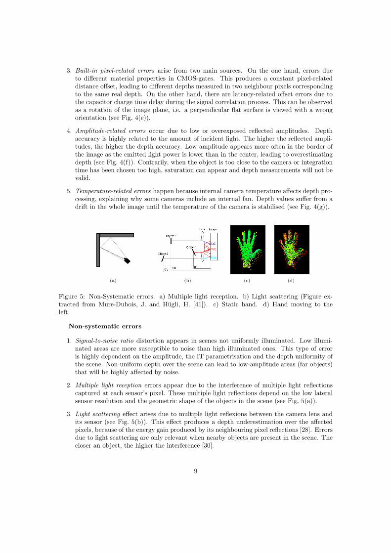
Figure 5: Non-Systematic errors. a) Multiple light reception. b) Light scattering (Figure ex-tracted from Mure-Dubois, J. and Hugli, H. [41]). c) Static hand. d) Hand moving to theleft.
Non-systematic errors
1. Signal-to-noise ratio distortion appears in scenes not uniformly illuminated. Low illumi-nated areas are more susceptible to noise than high illuminated ones. This type of erroris highly dependent on the amplitude, the IT parametrisation and the depth uniformity ofthe scene. Non-uniform depth over the scene can lead to low-amplitude areas (far objects)that will be highly affected by noise.
2. Multiple light reception errors appear due to the interference of multiple light reflectionscaptured at each sensor’s pixel. These multiple light reflections depend on the low lateralsensor resolution and the geometric shape of the objects in the scene (see Fig. 5(a)).
3. Light scattering effect arises due to multiple light reflexions between the camera lens andits sensor (see Fig. 5(b)). This effect produces a depth underestimation over the affectedpixels, because of the energy gain produced by its neighbouring pixel reflections [28]. Errorsdue to light scattering are only relevant when nearby objects are present in the scene. Thecloser an object, the higher the interference [30].
9

4. Motion blurring, present when traditional cameras are used in dynamic environments,appears also with ToF cameras. This is due to the physical motion of the objects or thecamera during the integration time used for sampling (see Fig. 5(c-d)).
Conclusions
This task has contributed to facilitate the evaluation of ToF cameras for robotic purposes and, inthe case of being suitable for an application, to easily identify their advantages, drawbacks andconstraints [20]. Also, thanks to the ToF camera characterization, a better depth measurementestimation can be achieved by using this information to develop new calibration and filteringalgorithms [22].
4.3 Task 2: Modelling under uncertainty
In order to understand a previously unknown real scene, a model of it should be build. Takinginto account the uncertainty of the sensor’s measurements into the 3D data registration processis a key point for correctly build such a model. The use of uncertainty reduction approaches,such as view-based SLAM can dramatically help to improve the 3D registration process if apre-defined and closed-loop viewpoint trajectory is performed. During this task, efforts will beconcentrated on studying and developing a method for propagating the sensor’s uncertainty tothe sensor’s pose through a point cloud registration process and to apply view-based SLAM forimproving the 3D model.
This task has already been fulfilled. Therefore, a summary of the achieved contributions ishere presented:
3D Modeling under an uncertainty reduction approach
Data fusion for scene or model augmentation has been typically addressed by error minimizationmethods, such as bundle adjustment [55] or structure from motion [16]. These approaches areoften not suitable for real time computation given their iterative nature. Recursive state esti-mation (e.g., SLAM) is a more suitable choice. The classical EKF-based approach to SLAM forfeature-based scene augmentation is also not viable for real time modeling since it requires thecomputation of fully correlated covariances at each step [18]. The proposal is to use a view-basedinformation-form SLAM method that a) does not maintain a large number of feature estimates,but only a reduced number of pose estimates, and b) is efficiently computed in information form,exploiting the sparsity of such filtering representation [26]. Advantage is taken of the fact thatthe first and last images in a circular sequence around an object overlap. This allows to imposethe loop-closure constraint.
The point cloud registration method used in this approach is based on the well-known ICPalgorithm [8, 11, 60], and its variants [40, 47]. The probabilistic data fusion mechanism used inthis work requires first order approximations of error propagation. That is, covariance estimatesof sensor uncertainty must be propagated through the ICP cost function to compute relativepose covariance estimates between the two generative viewpoints.
The decision of using one cost function or another plays an important role during errorpropagation, since its derivatives need to be computed. In its simplest form, given a set ofmatching points from two consecutive point clouds mi = (a, b), the ICP cost function takes theform
ε(mi,xi) =∑
||xi(b)− a||2. (1)
10

An accurate covariance approximation can be computed using a Monte Carlo simulation, butthis is a time-consuming solution and, since speed of execution is really a needed characteristic,finding a closed-form solution is desirable.
Given that the ICP algorithm is basically a cost function minimization procedure, an implicitfunction between input (point clouds) and the output (the pose) is defined by the minimizationprocess [12]. Albeit the implicit function can not be explicitly known, its Jacobian matrix canbe computed. Consequently, the estimated covariance matrix can be computed using the usualfirst-order approximation of an explicit function
Σi = ∇f Σs ∇fT, (2)
where ∇f is the explicit function’s Jacobian matrix, Σs the sensor covariance matrix and Σi thecomputed relative pose covariance matrix.
The Jacobian matrix of the ICP implicit function can be computed by means of the implicitfunction theorem. In our case, for an unconstrained minimization problem, the Jacobian matrixbecomes
∇f =
(
∂2ε
∂x2i
)−1∂2ε
∂mi ∂xi
. (3)
Since the approach uses the point to point Euclidean distance error as a cost function in theregistration process, the application of the implicit function theorem is straightforward. It isimportant to notice however that this type of approximation propagates the error from sensormeasurements to the sensor’s relative pose. Therefore, the parametrization of the cost functionwill have to include the real sensor measurements as its only input variables. For instance, if apoint-to-plane ICP algorithm is used, its point-to-plane function will have to be accommodatedinto the implicit function and derived consequently. It is not correct to pre-compute the virtualpoint of the plane correspondence and then apply a point-to-point cost function.
(a) Robot trajectory after all ICP results are aggre-gated
(b) Revised robot trajectory after the loop is closedwith the view-based SLAM method
Figure 6: Robot pose trajectory. Frame a) shows the calculated trajectory and uncertainty esti-mates after all ICP results are aggregated, but before the loop is closed. Each pose accumulatesthe estimated error from the previous pose. Frame b) once the loop is closed, uncertainty isreduced and the complete trajectory is corrected.
Conclusions
As a contribution, this task has achieved to improve 3D object modelling by propagating sen-sor’s uncertainty through a point cloud registration process. Iterative point cloud registration
11

algorithms, such as Iterative Closest Point (ICP), smoothly refine previous coarse registrationwithout taking into account the measurement uncertainty. This new approach significantly im-proves the overall 3D model once a loop-closure is achieved [19].
Fig. 6 shows the estimated robot trajectories for the cases of ICP relative pose aggregation,and SLAM-based loop closure. After closing the loop, the final trajectory (blue) is closer toa circular shape than not the one achieved purely from accumulating ICP motion estimates(red). The red trajectory tends to describe the typical spiral shape characteristic from erroraccumulation.
4.4 Task 3: Active sensing for 3D modelling of rigid objects
This task contains both tasks 3 and 4 from Section 2.1. Pre-defined trajectories constrain task’sversatility. Since the goal is to actively plan our next vantage point based on the current state ofthe data interpretation and the goal of the task, a more dynamic system should be implemented.Therefore, it is necessary to find a task-based criterion for generating multiple vantage points sothey can wisely be evaluated by an information-gain decision-making algorithm. For instance, aperfect match for 3D object modelling tasks is a combination of a shape-based viewpoint plannerand a viewpoint information-gain-based evaluation. During the development of this task, a stayat the German Aerospace Center (DLR) has been carried out under the supervision of MichaelSuppa and Stefan Fuchs where the studies have been focused on:
Task 3.1 Reviewing the current active sensing techniques for 3D object modelling (Next-Best-View algorithms). Special attention will be paid to:
1. Shape-based viewpoint planning techniques.
2. Information-gain-based evaluation methods.
Task 3.2 Combining shape-based viewpoint planning techniques with information-gain-basedevaluation for optimal 3D object modelling.
Task 3.3 Learning and applying depth calibration and filtering techniques over ToF camerasmeasurements.
Since this task has already been fulfilled, a summary of the achieved contributions is herepresented:
Shape-based viewpoint planner
In order to determine a new vantage point accordingly to the information gain, a search spaceconsisting of multiple viewpoints (possible sensor positions and orientations) is required as input.Since the workspace around an object features an infinite number of views, many authors reducethe search space by sampling candidate views around an approximate sphere or cylinder [7, 43,56]. Their candidate views always point to the center of their figures and, consequently, thesensor can not be positioned in a way that achieves optimal modeling results.
In this work, the Viewpoint Estimator [34] algorithm is used. This algorithm generatesviewpoints by detecting boundary trends in a triangular mesh. It works as follows. Once new3D data are acquired, a triangular mesh is reconstructed in a real-time stream as suggested by [9].A quadratic patch is then fitted to each boundary region and new viewpoints, perpendicular tothose patches, are then generated. Therefore, the search space is not limited to a set of pre-defined poses over a sphere or cylinder but it allows for any position and orientation. Dependingon their position, relative to the sensor, the detected boundaries are classified as left, right, top
12

(a) Boundary classification (b) Quadratic patch fitting
Figure 7: Example of two boundaries obtained from a partial camel mesh, which are classifiedas left boundaries. A region growing is performed in order to fit a quadratic patch.
and bottom. In their work, the next viewpoint was chosen heuristically by first going throughthe left, then right, top and bottom boundaries. Figure 7 shows an example of two boundariesclassified as left and the subsequent region growing, which is used to fit a quadratic patch.
Information-gain-based evaluation method
In Information Theory, information gain is a probabilistic measure of how significant a newstate estimate of the environment is. The concept of information gain is equivalent to the one ofuncertainty or entropy reduction. Entropy, as defined by [51], is computed as:
H(x) = −∑
X
p(x) log p(x), (4)
where X is a finite set of values of a discrete random variable x that has p(x) as probabilitydistribution function. For a n multivariate Gaussian distribution with covariance matrix Σ,entropy can be computed as:
H(x) =1
2log((2π)n|Σ|). (5)
As [52] already pointed out, using the determinant over all possible measurements for computingthe information gain is computationally expensive. Based on his work, our approach uses thetrace of the covariance matrix instead of its determinant and, therefore, efficiently computes theoverall gain. This is possible thanks to having the same representation units for all the observablefeatures and, consequently, avoiding scalability problems. Finally, and despising the constants,the entropy of a discrete random variable can be efficiently computed as:
H(x) =
3n∑
i=0
log(Σii). (6)
13

Scene Representation: 3D Occupancy Grid
A 3D occupancy grid is a map of a 3D space represented by a set of random variables, whichare uniformly distributed on a discrete grid. These random variables are binary and specifywhether each of the grid cells is occupied or free. Usually occupancy grid maps are used forbuilding a consistent map after solving the SLAM problem, since they assume exact robot’s poseinformation [54]. In a different way, our approach does not use the occupancy grid map as a finalresult but as a tool to evaluate the information gain of multiple possible view poses.
Our 3D occupancy grid map is based on a probabilistic voxel space defined by a multireso-lution octree structure. All 3D grid cells, also called voxels, have associated a covariance matrixdepending on all the history of measurements. At the same time, each voxel is defined by threepossible occupancy types: occupied, free or unknown. By using the covariance matrix as anuncertainty voxel-related measurement, our approach can optimally obtain the information gaintaking into account the orientation of the sensor. This is an important feature when using anoisy sensor such as a ToF camera, since the error is usually bigger on one component.
(a) (b) (c) (d) (e) (f)
Figure 8: Graphical interpretation through ellipsoids of the covariance reduction inside a voxel.Figure a) shows two independent simulated readings of a point in space, which are taken tobe perpendicular for clarity. Figure d) shows the a priori uncertainty of an unknown voxelrepresented as a covariance matrix and visualized as a sphere inscribed inside the voxel cube.Pairs of figures (b-e) and (c-f) show how the covariance of a voxel gets updated after combiningone or both readings, respectively.
Expected Gain Using an Occupancy Grid
Initially, all voxel states are set to unknown, state with the highest uncertainty. Once new sensordata are obtained, the states of all voxels intersected by a ray are updated. Depending on whethera voxel is crossed by a ray-trace or whether it encloses a new measurement, the voxel state isset to free or to occupied, respectively. Also, each occupied voxel is assigned its measurementcovariance matrix Σi in order to posteriorly compute the information gain of new viewpoints. Ifthe voxel was previously defined occupied, both the new covariance and the former are combinedas shown in Fig. 8 by
(Σi)−1 = (Σt−1
i)−1 + (Σt
i)−1. (7)
Only voxels with unknown and occupied states would be considered for estimating the infor-mation gain, since free voxels do not provide any information. The reason for this behaviouris to minimize the effect of non-filtered noise and possible miss-readings due to non-systematicToF camera errors. Once the viewpoint estimator recommends a set of n viewpoints, their ex-pected information gain (IG) is computed. Every viewpoint is simulated by ray-tracing fromthe sensor’s pose to the occupancy grid. Each colliding ray updates the corresponding voxel’s
14

covariance matrix and a copy is kept in memory as a sparse matrix
A =
Σ0 0 · · · 0
0 Σ1. . .
......
. . .. . . 0
0 · · · 0 Σn
. (8)
Finally, the overal expected information gain is computed as
IG =
3n∑
i=0
log(Aii), (9)
Conclusions
The achievement of this task has contributed to extend information-gain decision-making as atask-based criterion for active sensing [23]. Active view planning is viewed as a space characteri-zation task whose goal is to answer the question: where should the sensor be placed for locatingspecific characteristics? Because it involves spatial characteristics (or at least located in space),the proposed approach uses a voxelized space where each voxel contains a complete 3×3 covari-ance. This representation allows to account not only for exploration (unknown areas) but alsofor refinement, that is, the information gain of seeing characteristics again from a different pointof view.
4.5 Task 4: Vantage point for disambiguation purposes
Once shape-based viewpoint planning techniques have been satisfactorily tested for raw 3D dataexploration purposes (modelling), higher level features can be abstracted from the scene, andconsequently more complex tasks can be achieved. For instance, an incremental step towardsactive sensing would be the computation of a vantage point for disambiguation purposes. Ambi-guity into a scene appears when, after feature model fitting evaluation, low confident values arereturned or also when specific 3D features are detected. Vantage point planning strategies arethen necessary to add new information into the system and therefore clarify its perception.This task can be divided in two sub-tasks:
Task 4.1 Improve scene segmentation by combining color/intensity images with model-basedfitting and depth data.
Task 4.2 Review of 3D feature extraction algorithms. If needed, develop new features for spe-cific plant structure disambiguation purposes.
This is the last completed task, and these are the achieved contributions:
Scene segmentation
Here it is presented a novel algorithm for the segmentation of dense color images into surfacepatches using sparse depth data, acquired using either ToF or stereo techniques. The color imagesare segmented at different resolutions, 3D surfaces are then fitted to the color-segment areasusing sparse depth data, and a new segmentation is found by minimizing the total fitting errorwhile giving preference to segments at lower resolutions. The method has been demonstratedto segment a variety of images of domestic objects and plants into their composite surfaces and
15

shown to be applicable to different kinds of depth information, i.e., ToF and stereo. The methodshowed robust results for the given parameter set and also was demonstrated to work well forimages of plants that contain many depth layers, occlusions, and leaf boundaries of weak contrast.
(a) (b) (c)
(d) (e) (f)
Figure 9: Segmentation results for plants. (a-d): Original color image together with an exemplarycandidate segment boundary (marked in red) (see text). (b-e): Initial ToF sparse depth plottedtogether with final segment boundaries. (c-f): Fitted depth using segment surface models plottedtogether with the final segment boundaries.
Plant images are challenging because they contain many depth layers and occlusions, causedby overlapping leaves, and weak contrast boundaries separating adjacent leaves. The resultsare presented in Fig. 9. In the left panels, the original color images are shown. In the middlepanels, final segment boundaries (after region growing) are presented together with the initialdepth data. In the right panels, the final fitted depths are shown together with the final segmentboundaries. Even though plants exhibit complicated shapes and have many occlusions, mostof the main surfaces have been found, often corresponding to leaves or at least part of leaves,and curved shapes could be modelled correctly in most cases (for example the large leaf at thebottom in Fig. 9(a)). Basic segment properties such as mean color, size, and mean fitting errorare computed, and, based on these criteria, candidate segments (e.g. for robot manipulation)are selected representing leaf structures. An exemplary candidate segment has been marked redfor each plant (Fig. 9, left panels). Also the center point of the segments has been marked red.
Features for disambiguation
Here, a novel method to efficiently estimate a new vantage point for improving plant monitoring ispresented. The method takes advantage of jump-edge flying points, typical erroneous data froma ToF camera, for finding a suitable solution to two common monitoring tasks, getting a betterview of an occluded target leaf and resolving ambiguity in the number of leaves. The methodcan be executed in real-time since it does not use any cost function minimization approach orany complex leaf model fitting but a geometrical approach and a simple planar leaf model.
Jump-edge measurements are a consequence of false measurements and therefore generallyfiltered from the data sets [24, 28, 31], even the new Kinect sensor filters internally these type of
16

misreadings. But, for the proposed monitoring tasks, the appearance of these false measurementsare indicative of possible model misinterpretation or object occlusion. Figure 10(a) shows aschematic representation of how such a vantage point is computed.
45o
NBV
plane 1
plane 2
jump
edge
current
view
(a) 2D new vantage point schematicrepresentation
(b) Jump-edge points (Blue)
Figure 10: False depth measurements (jump-edge points) detection helps to compute the nextviewpoint to uncover occluded leaves and to disambiguate the number of observed leaves. Figure(a) shows the 2D schematic representation of the algorithm. Figure (b) shows, in blue, the 3Djump-edge points.
(a) (b) (c) (d)
(e) (f) (g) (h)
Figure 11: Scene containing a detected leaf occlusion. Top row shows the scene before applyingthe vantage point algorithm, images (a-d). Bottom row shows the scene observed from the newviewpoint, images (e-h).
Figure 11 shows the resulting data of a scene where an occlusion of a leaf is clearly identified.By executing the jump-edge filter over the 3D data, the countours of each leaf are extracted(Fig. 11(b)). At the same time, the plane segmentation process provides the estimation of the
17

different planes (Fig. 11(c)). Figure 11(d) shows, in a 3D rotated view, the extracted jump-edgepoints that fall just in the frontier between both leaves. These points are the ones that allowus to compute the vantage point whose result is displayed at the bottom row of Fig. 11. Bycomparing the image pairs Fig. 11(a, e) and Fig. 11(c, g), it can be seen by moving the camerato the computed vantage point the overall perception of the occluded leaf surface is significallyimproved.
Conclusions
The completion of this task has contributed to develop novel algorithms for leaf segmentationand task-related 3D feature extraction for initial active sensing purposes [21]. The identificationof the different parts of a plant and the detection of significant spatial features will provide thenecessary clues for solving higher complexity active sensing tasks.
4.6 Task 5: Task-oriented active sensing of complex objects (plants)
This task is dedicated to build a unified framework for complex task-oriented active sensing drivenby a 3D-space-based information-gain goal. This research aims to define a set of exploratorycomplex tasks over plants that profit from this approach. Tasks will be such as: what is theoverall occupied space of a plant, what is its topology or which is the best leaf for probing onthe plant. During this stage the studies will also focus on how to extend the use of ToF camerasunder different illumination situations in order to cover as many as possible plant’s location, suchas outdoor (where sun light distorts the readings) or indoor (where light is under control).
Task 5.1 Detect external illumination and control camera parameters for depth acquisitionimprovement.
Task 5.2 Unify the task-oriented active sensing approach.
1. Describe and characterize exploratory tasks over plants.
2. Build task-related cost functions to partially pre-model the scene.
Expected contributions
At the end of the execution of this task, it is expected to have finished all the experimental workand to have developed a unified framework for task-oriented active sensing based on 3D-space-based information-gain.
Task 6: Compilation of results
Task 6 is assigned to the final duty of gathering together the experimental data and analysingthe overall results in order to let the author write down and submit his PhD thesis.
Figure 12 presents the schedule for the tasks described through Sections 4.1 to 4.6 in aGantt chart that spans over three years, in this, T stands for a three months period, so that T1represents the first three months of a year. The tasks already attained are shown with crosshatchpoints.
18

2008 2009 2010 2011 2012 2013
T3T4T1T2T3T4T1T2T3T4T1T2T3T4T1T2T3T4T1T2
PhD Formation Period
Task 1
ToF cam. applicability
ToF cam. characterization
Task 2
Point cloud registration
Uncertainty propagation
Task 3
ToF cam. calibration
Combined active sensing
Stay at DLR
Task 4
Color+depth segmentation
3D features for active sensing
Task 5
Active sensor parametrization
Unified task-oriented approach
Task 6
Compilation of results
Writing
Public defense
Figure 12: Workplan of the proposed thesis
5 Resources
Except for a 6 months stay at the German Aerospace Center (DLR), all the work has been andwill be developed under the framework of the Perception and Manipulation sub-line at the Institutde Robotica i Informatica Industrial (UPC-CSIC) from Barcelona. Funding has been obtainedfrom several projects at European, National and Regional level, such as: PACOPLUS (IST-FP6-
19

IP-027657), PAU (DPI2008-06022), GARNICS (FP7-247947), SGR ROBOTICA (2009SGR155)and PAU+(DPI2011-27510). The author is financed by a JAEPredoc grant provided by theSpanish Council of Scientific Research (CSIC).
6 Publications
In this section, the reader can find the complete list of accepted and submitted publications sincethe beginning of the PhD:
Journals
1. S. Foix, S. Kriegel, S. Fuchs, G. Alenya and C. Torras. “Explicit modelling of ToF camerauncertainty to improve complex 3D shape acquisition”, submitted to a journal.
2. G. Alenya, B.Dellen, S. Foix and C. Torras. “Leaf segmentation from ToF data for robotizedplant probing,” IEEE Robotics and Automation Magazine, to appear in 2012.
3. S. Foix, G. Alenya and C. Torras. “Lock-in time-of-flight (ToF) cameras: a survey,” IEEESensors Journal, 11(9): 1917-1926, 2011.
Conferences and workshops
1. W. Kizma, S. Foix and G. Alenya. “Plant leaf analysis using Time of Flight camera undersun, shadow and room conditions,” Paper submitted, 2012.
2. S. Foix, S. Kriegel, S. Fuchs, G. Alenya and C. Torras. “Information-gain view planningfor free-fom object reconstruction with a 3D ToF camera,” International Conference onAdvanced Concepts for Intelligent Vision Systems, 2012.
3. B. Dellen, G. Alenya, S. Foix and C. Torras. “Segmenting ToF data into surface patches forrobotized leaf probing,” accepted at IEEE IROS Workshop on agricultural robotics, 2012,Algarve, Portugal.
4. S. Foix, G. Alenya and C. Torras. “Towards plant monitoring through next best view,”14th International Conference of the Catalan Association for Artificial Intelligence, 2011,Lleida, in Artificial Intelligence Research and Development, Vol 232 of Frontiers in ArtificialIntelligence and Applications, pp. 101-109, IOS Press.
5. B. Dellen, G. Alenya, S. Foix and C. Torras. “Segmenting color images into surface patchesby exploiting sparse depth data,” IEEE Workshop on Applications of Computer Vision,2011, Kona, Hawaii, pp. 591-598.
6. S. Foix, G. Alenya, J. Andrade-Cetto and C. Torras. “Object modelling using a ToF cameraunder an uncertainty reduction approach,” IEEE International Conference on Robotics andAutomation, 2010, Anchorage, pp. 1306-1312.
7. B. Dellen, G. Alenya, S. Foix and C. Torras. “3D object reconstruction from Swissrangersensor data using a spring-mass model,” 4th International Conference on Computer VisionTheory and Applications, 2009, Lisboa, pp. 368-372, 2009, INSTICC Press.
20

Technical reports
1. S. Foix, G. Alenya and C. Torras. “Exploitation of time-of-flight (ToF) cameras,” TechnicalReport IRI-TR-10-07, Institut de Robotica i Informatica Industrial, CSIC-UPC, 2010.
7 Bibliography
[1] 3D vision sensors, http://www.ifm.com. Ifm electronic gmbh, 2009.
[2] SR-Cameras, http://www.mesa-imaging.ch. MESA Imaging AG, 2009.
[3] PMD-Cameras, http://www.pmdtec.com. PMDTechnologies GmbH, 2009.
[4] G. Alenya, B. Dellen, and C. Torras. 3d modelling of leaves from color and tof data forrobotized plant measuring. In Proc. IEEE Int. Conf. Robot. Automat., pages 3408–3414,Shanghai, May 2011.
[5] T. Arbel and F. P. Ferrie. On the sequential accumulation of evidence. Int. J. Comput.Vision, 43(3):205–230, 2001. doi: 10.1023/A:1011187530616.
[6] R Bajcsy. Active perception. Proc. IEEE, 76:966–1005, 1988.
[7] J. E. Banta, L. M. Wong, C. Dumont, and M. A. Abidi. A next-best-view system forautonomous 3-D object reconstruction. IEEE Trans. Syst., Man, Cybern. A, 30(5):589–598,Sep. 2000.
[8] P.J. Besl and N.D. McKay. A method for registration of 3D shapes. IEEE Trans. PatternAnal. Machine Intell., 14(2):239–256, Feb. 1992.
[9] Tim Bodenmuller. Streaming surface reconstruction from real time 3D measurements. PhDthesis, Technische Universitat Munchen (TUM), 2009.
[10] S. Chen, Y. Li, J. Zhang, and W. Wang. Active sensor planning for multiview vision tasks.Springer-Verlag, Berlin Heidelberg, 2008.
[11] Y. Chen and G. Medioni. Object modeling by registration os multiples ranges images. InProc. IEEE Int. Conf. Robot. Automat., volume 3, pages 2724–2729, Sacramento, Apr. 1991.
[12] J.C. Clarke. Modelling uncertainty: A primer. Technical Report 2161/98, University ofOxford. Dept. Engineering science, 1998.
[13] C. I. Connolly. The determination of next best views. In Proc. IEEE Int. Conf. Robot.Automat., volume 2, pages 432–435, St. Louis, Mar. 1985.
[14] B. Curless and M. Levoy. A volumetric method for building complex models from rangeimages. In Computer Graphics. Proc. ACM SIGGRAPH Conf., pages 303–312, New York,Aug. 1996. ACM Press.
[15] F. Deinzer, C. Derichs, and H. Niemann. A framework for actively selecting viewpoints inobject recognition. Int. J. Pattern Recogn. Artif. Intell., 23(4):765–799, 2009.
21

[16] F. Dellaert, S.M. Seitz, C.E. Thorpe, and S. Thrun. Structure from motion without cor-respondence. In Proc. 14th IEEE Conf. Comput. Vision Pattern Recog., volume 2, pages557–564, Hilton Head, SC, Jun. 2000.
[17] J. Denzler and C.M. Brown. Information theoretic sensor data selection for active objectrecognition and state estimation. IEEE Trans. Pattern Anal. Machine Intell., 24(2):145–157,2002. doi: 10.1109/34.982896.
[18] M. W. M. G. Dissanayake, P. Newman, S. Clark, H. F. Durrant-Whyte, and M. Csorba. Asolution to the simultaneous localization and map building (SLAM) problem. IEEE Trans.Robot. Automat., 17(3):229–241, Jun. 2001.
[19] S. Foix, G. Alenya, J. Andrade-Cetto, and C. Torras. Object modeling using a ToF cameraunder an uncertainty reduction approach. In Proc. IEEE Int. Conf. Robot. Automat., pages1306–1312, Anchorage, May 2010.
[20] S. Foix, G. Alenya, and C. Torras. Exploitation of Time-of-Flight (ToF) cameras. TechnicalReport IRI-DT-10-07, IRI, UPC, 2010.
[21] S. Foix, G. Alenya, and C. Torras. Towards plant monitoring through next best view. InProc. 14th Int. Conf. Cat. Assoc. Artificial Intelligence, Lleida, Oct. 2011.
[22] S. Foix, G. Alenya, and C. Torras. Lock-in Time-of-Flight (ToF) cameras: a survey. IEEESensors J., 11(9):1917–1926, Sep. 2011.
[23] S. Foix, S. Kriegel, S. Fuchs, G. Alenya, and C. Torras. Information-gain view planningfor free-form object reconstruction with a 3D ToF camera. In Internatial Conference onAdvanced Concepts for Intelligent Vision Systems, Sep. 2012.
[24] S. Fuchs and S. May. Calibration and registration for precise surface reconstruction withtime of flight cameras. Int. J. Int. Syst. Tech. App., 5(3-4):274–284, 2008. ISSN 1740-8865.doi: http://dx.doi.org/10.1504/IJISTA.2008.021290.
[25] S.B. Gokturk, H. Yalcin, and C. Bamji. A time-of-flight depth sensor - system description,issues and solutions. In Proc. IEEE CVPR Workshops, pages 35–35, Washington, D. C.,June 2004. doi: 10.1109/CVPR.2004.17.
[26] V. Ila, J. M. Porta, and J. Andrade-Cetto. Information-based compact Pose SLAM. IEEETrans. Robot., 26(1):78–93, Feb. 2010.
[27] Z. Jia, Y. Chang, and T Chen. A general boosting-based framework for active objectrecognition. In Proc. British Machine Vision Conf., pages 46.1–46.11. BMVA Press, Sep.2010. doi: 10.5244/C.24.46.
[28] T. Kahlmann and H. Ingensand. Calibration and development for increased accuracy of 3Drange imaging cameras. J. Appl. Geodesy, 2(1):1–11, 2008. doi: 10.1515/JAG.2008.001.
[29] T. Kahlmann, F. Remondino, and H. Ingensand. Calibration for increased accuracy of therange imaging camera SwissrangerTM . In ISPRS Commission V Symposium, pages 136–141,Dresden, Sep. 2006.
[30] W. Karel. Integrated range camera calibration using image sequences from hand-held oper-ation. In Proc. ISPRS Conf., volume 37, pages 945–952, Beijing, Jul. 2008.
22

[31] W. Karel, P. Dorninger, and N. Pfeifer. In situ determination of range camera qualityparameters by segmentation. In Proc. 8th Int. Conf. on Opt. 3D Meas. Tech., pages 109 –116, Zurich, July 2007.
[32] A. Kolb, E. Barth, R. Koch, and R. Larsen. Time-of-flight sensors in computer graphics. InEurographics (State-of-the-Art Report), pages 119–134, 2009.
[33] Bjorn Krebs, M. Burkhardt, and Bernd Korn. Handling uncertainty in 3d object recognitionusing bayesian networks. In H. Burkhardt and B. Neumann, editors, Proc. 5th EuropeanConf. Comput. Vision, volume 2 of Lect. Notes Comput. Sci., pages 782–795, Freiburg, Jun.1998.
[34] S. Kriegel, T. Bodenmuller, M. Suppa, and G. Hirzinger. A surface-based next-best-viewapproach for automated 3D model completion of unknown objects. In Proc. IEEE Int. Conf.Robot. Automat., pages 4869–4874, Shanghai, May 2011.
[35] R. Lange. 3D time-of-flight distance measurement with custom solid-state image sensors inCMOS/CCD-technoloty. PhD thesis, Univ. Siegen, Germany, 2000.
[36] C.B. Madsen and H.I. Christensen. A viewpoint planning strategy for determining trueangles on polyhedral objects by camera alignment. IEEE Trans. Pattern Anal. MachineIntell., 19(2):158 –163, Feb. 1997. doi: 10.1109/34.574798.
[37] N. Massios and R. Fisher. A best next view selection algorithm incorporating a qualitycriterion. In J. N. Carter and M. S. Nixon, editors, Proc. British Machine Vision Conf.,pages 780 – 789, Southampton, 1998.
[38] J. Maver and R. Bajcsy. Occlusions as a guide for planning the next view. IEEE Trans.Pattern Anal. Machine Intell., 15(5):417–433, May 1993.
[39] S. May, D. Droeschel, D. Holz, S. Fuchs, E. Malis, A. Nuchter, and J. Hertzberg. Three-dimensional mapping with time-of-flight cameras. J. Field Robotics, 26(11-12):934–965,Nov.-Dec. 2009. doi: 10.1002/rob.20321.
[40] J. Minguez, L. Montesano, and F. Lamiraux. Metric-based iterative closest point scanmatching for sensor displacement estimation. IEEE Trans. Robot., 22(5):1047–1054, Oct.2006.
[41] J. Mure-Dubois and H. Hugli. Real-time scattering compensation for time-of-flight camera.In Proc. 5th Int. Conf. Comput. Vision Systems, Bielefeld, March 2007. doi: 10.2390/biecoll-icvs2007-167.
[42] D. Papadopoulos-Orfanos and F. Schmitt. Automatic 3-d digitization using a laserrangefinder with a small field of view. In Proc. Int. Conf. Recent Advances in 3D Digi-tal Imag. and Model., Otawa, May 1997.
[43] R. Pito. A solution to the next best view problem for automated surface acquisition. IEEETrans. Pattern Anal. Machine Intell., 21(10):1016–1030, Oct. 1999. ISSN 0162-8828. doi:10.1109/34.799908.
[44] M.K. Reed and P.K. Allen. A robotic system for 3d model acquisition from multiple rangeimages. In Proc. IEEE Int. Conf. Robot. Automat., pages 2509 – 2514, Albuquerque, Apr.1997.
23

[45] S. Dutta Roy, S. Chaudhury, and S. Banerjee. Active recognition through next view plan-ning: A survey. Pattern Recogn., 37(3):429–446, 2004.
[46] S.D. Roy, S. Chaudhury, and S. Banerjee. Recognizing large 3-d objects through next viewplanning using an uncalibrated camera. In Proc. IEEE Int. Conf. Comput. Vision, volume 2,pages 276–281, Vancouver, Canada, Jul. 2001. doi: 10.1109/ICCV.2001.937636.
[47] S. Rusinkiewicz and M. Levoy. Efficient variants of the ICP algorithm. In Proc. 3rd Int.Conf. 3D Digital Imaging Modeling, pages 145–152, Quebec, May 2001.
[48] A. Saxena, L. Wong, and A. Y. Ng. Learning grasp strategies with partial shape information.In Proc. 23th AAAI Conf. on Artificial Intelligence, pages 1491–1494, Chicago, Jul. 2008.
[49] B. Schiele and J.L. Crowley. Transinformation for active object recognition. In Proc. IEEEInt. Conf. Comput. Vision, pages 249 –254, Bombay, Jan. 1998.
[50] W. R. Scott and G. Roth. View planning for automated three-dimensional object recon-struction and inspection. ACM Computing Surveys, 35(1):64–96, Mar. 2003.
[51] C. E. Shannon. A mathematical theory of communication. Bell Syst. Tech. J., 27:379–423,1948.
[52] R. Sim. Stable exploration for bearings-only SLAM. In Proc. IEEE Int. Conf. Robot.Automat., pages 2422–2427, Barcelona, Apr. 2005.
[53] G. Tarbox and S. Gottschlich. Planning for complete sensor coverage in inspection. Comput.Vis. Image Und., 61(1):84 – 111, Jan. 1995.
[54] S. Thrun, W. Burgard, and D. Fox. Probabilistic Robotics. MIT Press, Cambridge, 2005.
[55] B. Triggs, P.F. McLauchlan, R.I. Hartley, and A.W.Fitzgibbon. Bundle adjustment - Amodern synthesis. In Proc. Int. Workshop on Vision Algorithms, volume 1883 of Lect.Notes Comput. Sci., pages 153–177, Corfu, Sep. 1999.
[56] J. I. Vasquez-Gomez, E. Lopez-Damian, and L. E. Sucar. View planning for 3D objectreconstruction. In Proc. IEEE/RSJ Int. Conf. Intell. Robots Syst., pages 4015–4020, St.Louis, USA, Oct. 2009.
[57] P. Whaite and F. P. Ferrie. Autonomous exploration: Driven by uncertainty. IEEE Trans.Pattern Anal. Machine Intell., 19(3):193–205, Mar. 1997.
[58] Z. Xu, R. Schwarte, H. Heinol, B. Buxbaum, and T. Ringbeck. Smart pixel - photonic mixerdevice (PMD) / New System Concept of a 3D-imaging-on-a-chip. In Proc. 5th Int. Conf.Mechatronics and Machine Vision in Practice, pages 259–264, Nanjing, Sep. 1998.
[59] X. Yuan. A mechanism of automatic 3D object modeling. IEEE Trans. Pattern Anal.Machine Intell., 17(3):307–311, Mar. 1995. doi: 10.1109/34.368196.
[60] Z. Zhang. Iterative point matching for registration of free-form curves and surfaces. Int.J. Comput. Vision, 13:119–152, 1994.
24