task 1: product definition - eup network · 2020-03-06 · contact bio intelligence service s.a.s....
TRANSCRIPT
Contact BIO Intelligence Service S.A.S.
Shailendra Mudgal – Jonathan Bain
℡ +33 (0)1 53 90 11 80
European Commission DG ENTR
Preparatory Study for Eco-design
Requirements of EuPs [Contract N° S12.515749]
Lot 1
Refrigerating and freezing equipment: Service cabinets, blast cabinets, walk-in cold rooms, industrial process
chillers, water dispensers, ice-makers, dessert and beverage machines,
minibars, wine storage appliances and packaged condensing units
Task 1: Product definition
Final Report
May 2011
2
European Commission, DG ENTR
Preparatory Study for Eco-design Requirements of EuPs
ENTR Lot 1: Refrigerating and freezing equipment – Task 1
May 2011
Project Team
BIO Intelligence Service
Mr. Shailendra Mudgal
Mr. Benoît Tinetti
Mr. Jonathan Bain
Mr. Raul Cervantes
Mr. Alvaro de Prado Trigo
Disclaimer:
The project team does not accept any liability for any direct or indirect damage resulting from
the use of this report or its content.
This report contains the results of research by the authors and is not to be perceived as the
opinion of the European Commission. The European Commission is not responsible for any use
that may be made of the information contained therein.

May 2011
European Commission, DG ENTR
Proposal for Preparatory Study for Eco-design Requirements of EuPs
ENTR Lot 1: Refrigerating and freezing equipment – Task 1
3
Contents
1. Task 1: Definition ............................................................................................................ 11
1.1. Introduction ................................................................................................................... 11
1.1.1. Refrigeration market diversity ................................................................................................. 12
1.1.2. Institutional and other actors for standards and legislation .................................................... 12
1.1.2.1 EU level................................................................................................................................. 13
1.1.2.2 MS level ................................................................................................................................ 14
1.1.2.3 Third country standards organisations ................................................................................ 15
1.1.2.4 Other actors ......................................................................................................................... 16
1.1.3. Basic concepts of refrigeration ................................................................................................. 16
1.1.3.1 Cooling (or refrigeration) load ............................................................................................. 17
1.1.3.2 Vapour-compression cycle ................................................................................................... 18
1.1.3.3 Absorption cycle ................................................................................................................... 18
1.1.3.4 Total energy consumption (TEC) .......................................................................................... 19
1.1.3.5 Refrigerants .......................................................................................................................... 19
1.1.3.6 Refrigeration systems .......................................................................................................... 20
1.1.3.7 Efficiency measurement ....................................................................................................... 20
1.1.3.8 Insulation properties ............................................................................................................ 21
1.2. Product definitions ......................................................................................................... 22
1.2.1. Service cabinets ........................................................................................................................ 22
1.2.1.1 General product definition ................................................................................................... 22
1.2.1.2 Existing product definitions ................................................................................................. 22
1.2.1.3 Product description .............................................................................................................. 24
1.2.1.4 Functional unit and performance parameter ...................................................................... 25
1.2.1.5 Service cabinet classification and scope for the study ......................................................... 26
1.2.2. Blast cabinets............................................................................................................................ 28
1.2.2.1 General product definition ................................................................................................... 28
1.2.2.2 Existing product definitions ................................................................................................. 28
1.2.2.3 Product description .............................................................................................................. 28
1.2.2.4 Functional unit and performance parameter ...................................................................... 30
1.2.2.5 Blast cabinets’ classification and scope for the study .......................................................... 31
1.2.3. Walk-in cold rooms................................................................................................................... 33
1.2.3.1 General product definition ................................................................................................... 33
1.2.3.2 Existing product definitions ................................................................................................. 33
1.2.3.3 Product description .............................................................................................................. 34
1.2.3.4 Functional unit and performance parameter ...................................................................... 36
4
European Commission, DG ENTR
Preparatory Study for Eco-design Requirements of EuPs
ENTR Lot 1: Refrigerating and freezing equipment – Task 1
May 2011
1.2.3.5 Walk-in cold rooms’ classification and scope for the study ................................................. 36
1.2.4. Process chillers .......................................................................................................................... 40
1.2.4.1 General product definition ................................................................................................... 40
1.2.4.2 Existing product definitions .................................................................................................. 40
1.2.4.3 Product description .............................................................................................................. 42
1.2.4.4 Functional unit and performance parameter ....................................................................... 47
1.2.4.5 Chiller classification and scope for the study ....................................................................... 48
1.2.5. Remote condensing units ......................................................................................................... 52
1.2.5.1 General product definition ................................................................................................... 52
1.2.5.2 Existing product definitions .................................................................................................. 53
1.2.5.3 Product description .............................................................................................................. 53
1.2.5.4 Functional unit and performance parameter ....................................................................... 55
1.2.5.5 Remote condensing units classification and scope for the study ........................................ 55
1.2.6. Prodcom definitions .................................................................................................................. 58
1.3. Product test standards, their development and other standards ...................................... 60
1.3.1. Service cabinets ........................................................................................................................ 60
1.3.1.1 EN ISO 23953:2005 (under revision) .................................................................................... 61
1.3.1.2 EN 441:1995 ......................................................................................................................... 63
1.3.1.3 DE DIN 18872 (draft standards in progress) ......................................................................... 66
1.3.1.4 ANSI/AHRI 1200-2008 (US) ................................................................................................... 66
1.3.1.5 US ASHRAE Standard 72-2005 .............................................................................................. 70
1.3.1.6 CAN/CSA-C827-98 (R2008) ................................................................................................... 70
1.3.1.7 Comparison of volume measurement methods .................................................................. 71
1.3.1.8 Testing and protocols ........................................................................................................... 72
1.3.2. Blast cabinets ............................................................................................................................ 75
1.3.2.1 EN 328:1999 ......................................................................................................................... 75
1.3.2.2 EN 327:2000 ......................................................................................................................... 75
1.3.2.3 DE DIN 8953/8954 ................................................................................................................ 75
1.3.3. Walk-in cold rooms ................................................................................................................... 75
1.3.3.1 Introduction ......................................................................................................................... 75
1.3.3.2 European Technical Approval Guideline (ETAG) 021 and 016 ............................................. 76
1.3.3.3 EN 14509:2006 ..................................................................................................................... 80
1.3.3.4 EN 13164:2009-02 and EN 13165:2009-02 .......................................................................... 80
1.3.3.5 EN 12664:2001, EN 12667:2001 and EN 12939:2001 .......................................................... 81
1.3.3.6 ISO 12567-1:2010 ................................................................................................................. 81
1.3.3.7 EN ISO 6946:2007 ................................................................................................................. 82
1.3.3.8 EN 12114:2000 ..................................................................................................................... 82

May 2011
European Commission, DG ENTR
Proposal for Preparatory Study for Eco-design Requirements of EuPs
ENTR Lot 1: Refrigerating and freezing equipment – Task 1
5
1.3.3.9 BS EN 4376-1:1991 ............................................................................................................... 83
1.3.3.10 Agreement on the international carriage of perishable foodstuffs (ATP)............................ 83
1.3.3.11 PAS 57:2003 ......................................................................................................................... 84
1.3.3.12 AHRI 1251 (SI) (and AHRI 1250 (I-P)) .................................................................................... 86
1.3.3.13 US test procedures for walk-in coolers and freezers ........................................................... 87
1.3.3.14 US DOE proposed test procedures for walk-in coolers and freezers ................................... 87
1.3.4. Process chillers ......................................................................................................................... 94
1.3.4.1 EN 14511:2007 ..................................................................................................................... 94
1.3.4.2 EN 15218:2006 ..................................................................................................................... 95
1.3.4.3 prEN 14825 ........................................................................................................................... 95
1.3.4.4 AHRI 550/590-2003 .............................................................................................................. 96
1.3.4.5 ANSI/AHRI 560-2000 ............................................................................................................ 99
1.3.4.6 CAN/CSA-C743-09 .............................................................................................................. 102
1.3.4.7 AS/NZS 4776: 2008 ............................................................................................................. 103
1.3.5. Remote condensing units ....................................................................................................... 103
1.3.5.1 EN 13771:2003/ EN 13771:2007 ........................................................................................ 103
1.3.5.2 EN 13215:2000 ................................................................................................................... 103
1.3.5.3 ASHRAE Standard 23-2005 ................................................................................................. 104
1.3.5.4 ISO/R 916:1968 .................................................................................................................. 104
1.3.6. Standards related to the design, use and safety of products ................................................ 105
1.3.6.1 EU EN 631-1:1993 – Gastronorm ....................................................................................... 105
1.3.6.2 EN 1672:1997 Food processing machinery hygiene requirements .................................... 105
1.3.6.3 EN ISO 14159:2002 ............................................................................................................. 105
1.3.6.4 EN 60335-2-24:2010 .......................................................................................................... 106
1.3.6.5 EN 12464-1:2004 ................................................................................................................ 107
1.3.6.6 FR NF AC D40-003:2006 ..................................................................................................... 107
1.3.6.7 DE VDMA 11499 Operation and use of refrigerated display cabinets ............................... 109
1.3.6.8 DE VDMA 24247 Energy efficiency of refrigerating systems.............................................. 109
1.3.6.9 US NSF/ANSI 7:2009 ........................................................................................................... 109
1.3.7. Standards affecting the use of refrigerants ........................................................................... 110
1.3.7.1 EU EN 378:2009 .................................................................................................................. 110
1.3.7.2 DE VDMA 24020 Operational requirements for refrigerating systems ............................. 111
1.3.7.3 US ASHRAE Standard 34-2008 ............................................................................................ 111
1.3.8. Summary of existing standards .............................................................................................. 111
1.3.8.1 Service cabinets.................................................................................................................. 112
1.3.8.2 Blast cabinets ..................................................................................................................... 112
1.3.8.3 Walk-in cold rooms ............................................................................................................ 113

6
European Commission, DG ENTR
Preparatory Study for Eco-design Requirements of EuPs
ENTR Lot 1: Refrigerating and freezing equipment – Task 1
May 2011
1.3.8.4 Process chillers ................................................................................................................... 114
1.3.8.5 Remote condensing units ................................................................................................... 114
1.4. Existing legislation and voluntary agreements ............................................................... 115
1.4.1. Service cabinets ...................................................................................................................... 116
1.4.1.1 UK ECA incentive scheme for plug-in commercial service cabinets ................................... 116
1.4.1.2 US DOE MEPS ..................................................................................................................... 117
1.4.1.3 US CEC MEPS ...................................................................................................................... 118
1.4.1.4 Canada CAN/CSA-C827-98 Energy performance standard for food service refrigerators
and freezers 119
1.4.1.5 Australia/New Zealand refrigerated display cabinets MEPS .............................................. 120
1.4.1.6 US Energy Star voluntary programme for commercial solid door refrigerators and
freezers 121
1.4.1.7 US CEE Commercial Kitchens Initiative............................................................................... 122
1.4.1.8 US AHRI certification programme for commercial refrigerated display merchandisers
and storage cabinets ................................................................................................................................ 122
1.4.2. Blast cabinets .......................................................................................................................... 123
1.4.2.1 FR commercial food preparation hygiene requirements law of 29/09/1997 .................... 123
1.4.2.2 UK Department of Health Guidelines ................................................................................. 123
1.4.2.3 Austrian Hygiene Certificate Guideline .............................................................................. 123
1.4.3. Walk-in cold rooms ................................................................................................................. 123
1.4.3.1 US minimum requirements for walk-in cold rooms and walk-in freezers .......................... 123
1.4.3.2 UK ECA incentive scheme for cellar cooling equipment .................................................... 125
1.4.3.3 PQS Quality Assurance protocol E01/CR/FR-VP2 ............................................................... 127
1.4.3.4 ATP agreement on the international carriage .................................................................... 128
1.4.4. Process chillers ........................................................................................................................ 131
1.4.4.1 EU EUROVENT certification programme for liquid chilling packages ................................. 131
1.4.4.2 UK ECA incentive scheme for packaged chillers (only for High temperature- Air
conditioning) 134
1.4.4.3 US ASHRAE 90.1-2007 ........................................................................................................ 136
1.4.4.4 CAN CSA-C743-09 performance standard for packaged water chillers ............................. 136
1.4.4.5 Australia/New Zealand water chillers MEPS ...................................................................... 137
1.4.5. Remote condensing units ....................................................................................................... 138
1.4.5.1 UK ECA incentive scheme for air-cooled condensing units ................................................ 138
1.4.6. EU environmental legislations ................................................................................................ 140
1.4.6.1 European Directive 2002/96/EC on Waste Electrical and Electronic Equipment (WEEE) .. 140
1.4.6.2 European Directive 2002/95/EC on the Restriction of the use of certain Hazardous
Substances in electrical and electronic equipment (RoHS) ..................................................................... 140
1.4.7. Legislation related to refrigerant fluids .................................................................................. 141
1.4.7.1 European Regulation N°2037/2000 on Ozone Depleting Substances (ODS) ..................... 141

May 2011
European Commission, DG ENTR
Proposal for Preparatory Study for Eco-design Requirements of EuPs
ENTR Lot 1: Refrigerating and freezing equipment – Task 1
7
1.4.7.2 European Regulation N° 842/2006 on certain fluorinated greenhouse gases ................... 142
1.4.7.3 DK statutory order 552....................................................................................................... 143
1.4.7.4 Austria Ordinance No 447/2002 ........................................................................................ 143
1.4.7.5 Norway - Tax and refund scheme for imported HFCs ........................................................ 143
1.4.8. Energy-efficiency and use legislation ..................................................................................... 144
1.4.8.1 EuP TREN Lot 13 – Legislation related to household refrigerating appliances .................. 144
1.4.8.2 EuP TREN Lot 11 – Electric motors ..................................................................................... 145
1.4.8.3 Legislation related to the lighting system .......................................................................... 147
1.4.8.4 Legislations related to tertiary and domestic lighting........................................................ 147
1.4.8.5 European Directive on Electromagnetic Compatibility (ECM) 2004/108/EC ..................... 147
1.4.8.6 European Directive on construction products 89/106/EEC ............................................... 147
1.4.9. Health and safety legislation .................................................................................................. 148
1.4.9.1 European Directive 95/16/EC on Machinery, amended by 2006/42/EC ........................... 148
1.4.9.2 European Directive 2001/95/EC on General Product Safety ............................................. 149
1.4.9.3 European Directive 73/23/EEC on Low Voltage Equipments (LVD) ................................... 149
1.4.9.4 Pressure Equipment Directive (PED) 1997/23/EC .............................................................. 149
1.4.9.5 European Directive 98/83/EC on quality of water ............................................................. 149
1.4.9.6 Hazard Analysis Critical Control Point (HACCP) .................................................................. 150
1.4.9.7 Summary of temperature and time constraints for cooked foodstuff .............................. 150
1.4.10. Other voluntary agreements ........................................................................................... 150
1.4.10.1 EUROVENT certification programmes for refrigeration components ................................ 150
1.4.10.2 ASERCOM certification of refrigerant compressors ........................................................... 150
1.4.10.3 DK demanufacture of refrigeration equipment ................................................................. 150
1.4.11. Summary of existing legislation and voluntary measures ............................................... 151
1.4.11.1 Service cabinets.................................................................................................................. 151
1.4.11.2 Blast cabinets ..................................................................................................................... 154
1.4.11.3 Walk-in cold rooms ............................................................................................................ 154
1.4.11.4 Process chillers ................................................................................................................... 155
1.4.11.5 Remote condensing units ................................................................................................... 155
1.5. Conclusions for Task 1 ................................................................................................... 157
ANNEXES ............................................................................................................................... 158
Annex 1-1: Additional standards related to refrigeration and freezing equipment ...................... 160
1.6. EN 153:2006 ................................................................................................................. 160
1.7. EN ISO 15502:2005 (corrigendum 1:2007) ...................................................................... 161
1.8. EN 28960:1993 (ISO 8960:1991) ..................................................................................... 164
1.9. ANSI/ARI 420-2008 ....................................................................................................... 164
1.10. ANSI/ARI 530-2005 ....................................................................................................... 165

8
European Commission, DG ENTR
Preparatory Study for Eco-design Requirements of EuPs
ENTR Lot 1: Refrigerating and freezing equipment – Task 1
May 2011
1.11. ANSI/ARI 520-2004 ....................................................................................................... 165
1.12. ANSI/ARI 540-2004 ....................................................................................................... 165
1.13. ISO 5149:1993 ............................................................................................................... 168
1.14. ATP agreement ............................................................................................................. 169
1.14.1. Introduction ..................................................................................................................... 169
1.14.2. Definitions ........................................................................................................................ 169
1.14.3. Requirements ................................................................................................................... 169
1.14.4. Test methods and procedures (Annex 1, Appendix 2 of the agreement) ....................... 171
1.14.4.1 Definitions and general principles (Section 1) .................................................................... 171
1.14.4.2 Insulating capacity of equipment (Section 2) ..................................................................... 171
1.14.4.3 Effectiveness of thermal appliances [applications] of the equipment (Section 3) ............. 172
1.14.4.4 Procedure for measuring the effective refrigerating capacity of unit when evaporator
is free from frost (Section 4) .................................................................................................................... 172
1.14.4.5 Checking the insulating capacity of equipment in service (Section 5) ............................... 173
1.14.4.6 Verifying the effectiveness of thermal appliances of equipment in service (Section 6) .... 174
1.14.5. Compliance and enforcement .......................................................................................... 175
1.15. Other related standards ................................................................................................ 177
Annex 1-2: Summary of data for selection of the Base Cases ...................................................... 179
Annex 1-3: Summary of data for minibars .................................................................................. 184
Annex 1-4: Summary of data for wine storage appliances .......................................................... 186
Annex 1-5: Summary of data for dessert and beverage machines ............................................... 188
1.15.1.1 General product definition ................................................................................................. 188
1.15.1.2 Existing product definitions ................................................................................................ 188
1.15.1.3 Product description ............................................................................................................ 188
1.15.1.4 Functional unit and performance parameter ..................................................................... 188
1.15.1.5 Dessert and beverage machine classification and preliminary scope for the study .......... 189
Annex 1-6: Summary of data for water dispensers ..................................................................... 190
1.15.1.6 General product definition ................................................................................................. 190
1.15.1.7 Existing product definitions ................................................................................................ 190
1.15.1.8 Product description ............................................................................................................ 190
1.15.1.9 Functional unit and performance parameter ..................................................................... 191
1.15.1.10 Water dispenser classification and water dispensers included in the scope ..................... 191
Annex 1-7: Summary of data for ice-makers .............................................................................. 194
1.15.1.11 General product definition ................................................................................................. 194
1.15.1.12 Existing product definitions ................................................................................................ 194
1.15.1.13 Product description ............................................................................................................ 194

May 2011
European Commission, DG ENTR
Proposal for Preparatory Study for Eco-design Requirements of EuPs
ENTR Lot 1: Refrigerating and freezing equipment – Task 1
9
1.15.1.14 Functional unit and performance parameter .................................................................... 196
1.15.1.15 Ice-maker classification and ice makers in the scope of the study .................................... 196
Annex 1-8: Other information ................................................................................................... 204
Glossary.................................................................................................................................... 208

10
European Commission, DG ENTR
Preparatory Study for Eco-design Requirements of EuPs
ENTR Lot 1: Refrigerating and freezing equipment – Task 1
May 2011

May 2011
European Commission, DG ENTR
Proposal for Preparatory Study for Eco-design Requirements of EuPs
ENTR Lot 1: Refrigerating and freezing equipment – Task 1
11
1. Task 1: Definition
1.1. INTRODUCTION
Task 1 provides a technical description of all products, including the suggested
functional unit, and preliminary data on energy consumption.
The product definitions are based in particular on definitions available from
external sources (e.g. EU trade statistics, existing standards and regulations,
voluntary initiatives, the industry, and dictionaries). Key technical parameters
impacting the environmental performance of the product are identified as a basis
for further analysis in the next steps of the study. Harmonised test standards and
additional sector-specific procedures for product-testing are identified and
discussed. Finally, Task 1 presents any relevant legislation, voluntary agreements,
and labelling initiatives at EU level, in Member States, and in third countries.
The Ecodesign Directive (2005/32/EC) is expected to improve the environmental
performance of major refrigerating and freezing equipment in the EU through
ecodesign. In this context, a first preparatory study (TREN Lot 121) was conducted
during 2006-07, focussing on refrigerated display cabinets (both remote and plug-
in), beverage coolers, ice-cream freezers, and cold vending machines. Commercial
refrigeration equipment and additional industrial refrigeration equipment, not
covered by TREN Lot 12 will be covered by this study, namely:
• service cabinets;
• blast cabinets;
• walk-in cold rooms;
• process chillers;
• water dispensers;
• ice-makers;
• dessert and beverage machines;
• minibars;
• wine storage appliances; and
• remote condensing units.
This study aims at proposing solutions to improve the energy performance of
these product categories and reduce their environmental impacts during their life-
cycle.
As in all Ecodesign preparatory studies, a common and coherent methodology2 is
used to analyse the environmental impact and improvement potential of the
products, and ecodesign options are analysed from a life cycle cost perspective.
This methodology consists of seven main tasks, conducted in an iterative manner
to allow integration of new information throughout the project.
1 BIO Intelligence Service, Ecodesign Preparatory Study TREN Lot 12, Final Report, European
Commission (DG TREN), 2007. Available at: www.ecofreezercom.org/documents_1.php 2 VHK, Methodology for Ecodesign of Energy-using Products (MEEuP), Final Report, European
Commission (DG ENTR), 2005. Available at: ec.europa.eu/enterprise/eco_design/finalreport1.pdf

12
European Commission, DG ENTR
Preparatory Study for Eco-design Requirements of EuPs
ENTR Lot 1: Refrigerating and freezing equipment – Task 1
May 2011
At an interim stage of the project, a matrix of data was developed to prioritise
product groups from the list described above. This information was drawn from
the literature and stakeholder input, and was distributed to stakeholders for
comment. The matrix is described in annex 1-2, and the following product groups
were selected in light of their significant potential for improvement through
ecodesign and subsequent reduction of environmental impacts across the EU.
These product groups were:
• service cabinets;
• blast cabinets;
• walk-in cold rooms;
• process chillers; and
• packaged remote condensing units.
The information relating to the remaining product groups is summarised in
annexes 1-3 to 1-7.
1.1.1. REFRIGERATION MARKET DIVERSITY
Refrigeration products covered in ENTR Lot 1 span a large range of applications
and the products are used in diverse environments such as supermarkets,
restaurants, hotels, pubs, cafés and industrial facilities. These products are
estimated to consume a significant proportion of electricity in the EU (as an
example, in the UK this is around 3% of total energy consumption and 1% of total
greenhouse gas emissions3). Moreover, they may cause other negative
environmental impacts during their life-cycle due to their material content, such as
refrigerants and insulating agents.
When designing such appliances to reduce the impacts related to climate change
and global warming, manufacturers usually focus on the energy requirement of
the appliance and on the choice of the refrigerant (e.g. HFCs, which are being
replaced by alternatives). Many such initiatives for a more environmentally-
friendly design may derive from various sources, such as national and international
regulations, financial incentives and manufacturers’ commitment towards the
environment. The end-user, although conscious of the energy performance of
these products (as they directly affect their electricity bills), is not always
influenced by environmental performance during their purchase decision.
1.1.2. INSTITUTIONAL AND OTHER ACTORS FOR STANDARDS AND LEGISLATION
Standards, legislation (such as Minimum Energy Performance Standards, MEPS)
and voluntary agreements related to the products covered by ENTR Lot 1 and
discussed in Task 1 have been developed at EU level, in individual MS, and in
several third countries.
3 Refrigeration Road Map. An action plan for the retail sector. Carbon Trust, 2010
May 2011
European Commission, DG ENTR
Proposal for Preparatory Study for Eco-design Requirements of EuPs
ENTR Lot 1: Refrigerating and freezing equipment – Task 1
13
1.1.2.1 EU level
The approach defined in the European Council (EC) Resolution of May 1985,
introduced, among other things, a clear separation of responsibilities between the
EC legislator and the European Standards Bodies (CEN4/CENELEC5) in the legal
framework allowing for the free movement of goods6:
• EC Directives define the "essential requirements", e.g., protection of
health and safety, which goods must meet when they are placed on the
market.
• The European standardisation bodies have the task of drawing up the
corresponding technical specifications meeting the essential requirements
of the directives; compliance with the standard will provide a presumption
of conformity with requirements of the directive. Such specifications are
referred to as "harmonised standards".
� European standards
European standards, denoted by prefix “EN”, are adopted by CEN, CENELEC or ETSI
and imply an obligation to implement an identical national standard and to
withdraw any conflicting national standards7. Such standards may also be issued
by an international standardisation organisation such as the International
Organisation for Standardisation (ISO) and the International Electrotechnical
Commission (IEC) and are recognised at both the international and EU levels (this
includes international standards that have been adopted by European Standards
Bodies, for example, “EN ISO” or “EN IEC” standards).
CEN/CENELEC internal regulations define a standard as a document, established by
consensus and approved by a recognised body that provides, for common and
repeated use, rules, guidelines or characteristics for activities or their results,
aimed at the achievement of the optimum degree of order in a given context.
Standards should be based on consolidated results of science, technology and
experience, and aimed at the promotion of optimum community benefits.
� European Organisation for Technical Approvals (EOTA)
The European Organisation of Technical Approvals (EOTA), which groups together
the national approvals bodies, can draw up technical approvals guidelines in
respect of a construction product or family of construction products, acting on a
mandate from the Commission and after consulting the Standing Committee on
Construction8, in the context of Directive 89/106/EEC on construction products
(§1.4.8.6). European technical approvals are used to assess the suitability of a
product for its intended use in cases where there is no harmonised standard, no
recognised national standard and no mandate for a European standard and where
the Commission feels, after consulting the Member States within the Standing
Committee on Construction, that a standard cannot or cannot yet be prepared.
4 European Committee for Standardisation: www.cen.eu
5 European Committee for Electrotechnical Standardisation: www.cenelec.eu
6 European Commission website:
ec.europa.eu/comm/enterprise/newapproach/standardization/harmstds/index_en.html 7 European Committee for Standardisation: www.cenorm.be/cenorm/index.htm
8 ec.europa.eu/enterprise/sectors/construction/documents/legislation/cpd/index_en.htm

14
European Commission, DG ENTR
Preparatory Study for Eco-design Requirements of EuPs
ENTR Lot 1: Refrigerating and freezing equipment – Task 1
May 2011
� European Federation of Catering Equipment Manufacturers (EFCEM)
EFCEM represents manufacturers of commercial kitchen equipment and includes
the key European national associations in its membership. The federation is active
in the formulation of standards for the industry and through its meetings seeks to
identify and act on issues of common interest.
� EUROVENT certification programme (EUROVENT)
The EUROVENT programme is a voluntary minimum performance and labelling
scheme which includes components, and products similar to the products within
the scope of ENTR Lot 1.
� Association of European Refrigeration Compressor and Control
Manufacturers (ASERCOM)
ASERCOM has established a certification scheme for the performance of
refrigeration compressors which aims at helping buyers to select their products
based on performance criteria.
1.1.2.2 MS level
Several EU Member States have also developed relevant standards and legislation
which are used internationally, such as France (FR), Germany (DE), Denmark (DK)
and the UK.
� Normes Française (FR NF)
In France, the national standards body, NF, develops various standards, including
those related to refrigeration and freezing equipment.
� Verband Deutscher Maschinen- und Anlagenbau (DE VDMA)
The German Engineering Federation, VDMA, is one of the key service provider
associations in Europe and offers the largest engineering industry network in
Europe. It is involved in the development of standards relating to refrigeration and
freezing equipment and systems.
� Enhanced Capital Allowance Scheme9 (UK ECA)
The UK ECA scheme was designed to encourage businesses to invest in energy
saving equipment allowing business to claim 100% first year capital allowance in
such investments10. Enhanced Capital Allowances (ECAs) can only be claimed on
energy-saving products listed in the Energy Technology List (ETL) that meet the
relevant criteria for their particular technology group. Energy using appliances
under this program include packaged chillers and commercial service cabinets
(plug-in only).
The ETL is divided into two parts:
• the Energy Technology Criteria List which contains details of the energy-
saving criteria that must be met for each of the technology classes; and
• the Energy Technology Product List which contains a list of products that
have been certified as meeting those standards.
9 ECA website: www.eca.gov.uk
10 ECA website: www.eca.gov.uk/etl/about/What+equipment+is+eligible.htm

May 2011
European Commission, DG ENTR
Proposal for Preparatory Study for Eco-design Requirements of EuPs
ENTR Lot 1: Refrigerating and freezing equipment – Task 1
15
� Market Transformation Programme11
(UK MTP)
The UK’s MTP was launched following a consultation paper12 issued by the
Environment & Business Division, in October 1997 and supports the development
and implementation of UK Government policy on sustainable products.
Domestic or commercial appliances including commercial refrigeration (liquid
chillers, service cabinets, cold rooms, cellar cooling equipment, ice-making
machines, refrigerated display cases, and refrigerated vending machines).
Please see annex 1-8 for more information on this programme.
1.1.2.3 Third country standards organisations
In the USA, several organisations are involved in the development of standards
which are relevant to Lot 1.
� Air-Conditioning, Heating, and Refrigeration Institute (AHRI)
The AHRI is the trade association representing manufacturers of air conditioning,
heating, and commercial refrigeration equipment. It also develops industry
standards and voluntary certification programs (AHRI performance certification
programs) for refrigeration equipment. The ARI standards mainly aim at measuring
the energy performance of the refrigeration appliances and of their components.
� American National Standards Institute (ANSI)
The ANSI is the American National Standards Institute that oversees the creation,
promulgation and use of norms and guidelines as well as accrediting programs that
assess conformance to standards. The ANSI standards mainly aim at enhancing
“the global competitiveness of U.S. business and the American quality of life”13.
� American Society of Heating, Refrigerating, and Air-conditioning Engineers
(ASHRAE)
This association develops standards for refrigeration appliances, heating
appliances, ventilation and air conditioning. They are also in charge of promoting
sustainability through research, publications and education.
� US Department of Energy (US DOE)
The US Energy Policy Act of 2005 prescribes new and amended energy
conservation standards and test procedures that apply to commercial refrigeration
equipment. The US Energy Independence and Security Act of 2007, enacted on 19
December 2007, establishes energy conservation standards for certain consumer
products and commercial and industrial equipment, including walk-in cold rooms
and walk-in freezers.
Final responsibility for the appliance of energy standards in policy measures
resides with the US DOE.
� California Energy Commission (US CEC)
11
MTP website: www.mtprog.com 12
Department of the Environment, Transport and the Regions.Energy Efficient Consumer Products: A
‘Market Transformation’ Strategy for More Sustainable Consumption, 1997 13
Website: www.ansi.org/standards_activities/overview/overview.aspx

16
European Commission, DG ENTR
Preparatory Study for Eco-design Requirements of EuPs
ENTR Lot 1: Refrigerating and freezing equipment – Task 1
May 2011
The US CEC adopted the California Appliance Efficiency Regulation, which became
effective 29th December2007. It was reviewed in 2009 and the document CEC-400-
2009-013 was produced.
The California Appliance Efficiency Regulation14 includes energy efficiency levels
for the following types of new appliances (within the scope of ENTR Lot 1):
automatic commercial ice-makers, refrigerators and freezers with doors (i.e.
service cabinets), walk-in refrigerators and freezers, and water dispensers. The
Regulation excludes certain refrigeration appliances with a volume exceeding 85
ft3 (2.4 m3) and automatic commercial ice-makers with a harvest rate lower than
50 lbs (22.7 kg)/24 hours or greater than 2,500 lbs. (1,134 kg)/24 hours.
� US Energy Star labelling programme
Energy Star is a joint program of US DOE and the US Environmental Protection
Agency. It is a scheme to promote energy efficiency, through setting minimum
performance standards and providing a label to those products that qualify,
allowing end-users to identify energy efficient products.
� Canada
In Canada, the standards organisation involved in standards development is the
Canadian Standards Association (CAN CSA).
Canadian Energy Efficiency Regulations set technical requirements for various
classes of Energy-using Products, including commercial refrigeration under which
products are separated into different product categories. Canadian regulations
affect products such as chillers, service cabinets, water and beverage dispensers
and ice-makers.
� Australia/New Zealand
In Australia and New Zealand, the organisations involved in the development of
standards are Standards Australia and Standards New Zealand (AS/NZS).
The MEPS programmes are mandatory in Australia by state government legislation
and regulations which give force to the relevant Australian Standards. Regulations
specify the general requirements for MEPS for appliances, including offences and
penalties if a party does not comply with the requirements.
1.1.2.4 Other actors
Many other actors are involved in the refrigerant market including, for example,
those that draft legislation for health and safety (for example, to maintain food
quality, maximum refrigeration storage temperatures are defined) and develop
voluntary schemes related to maintenance.
1.1.3. BASIC CONCEPTS OF REFRIGERATION
This section aims to facilitate the understanding of refrigeration technology. It
introduces the basic refrigeration concepts, provides a description of the two main
types of refrigeration cycles used in commercial refrigeration equipment, and the
fundamental components required. The design of any cooling appliance follows
some basic principles of thermodynamics:
14
Website: www.energy.ca.gov/appliances/2009regulations/

May 2011
European Commission, DG ENTR
Proposal for Preparatory Study for Eco-design Requirements of EuPs
ENTR Lot 1: Refrigerating and freezing equipment – Task 1
17
• Heat naturally flows from high to low temperature points.
• Energy in the form of heat is necessary to vaporise15 a liquid. During an
evaporation process, the liquid absorbs heat from its surroundings, thus
cooling its surroundings. Contrarily, a substance releases heat to its
surroundings during a condensation process16.
• The evaporating and condensing temperatures of a substance are
correlated with the pressure. If the pressure of a substance decreases, its
evaporating and condensing temperature will also decrease.
1.1.3.1 Cooling (or refrigeration) load
The cooling load (also called refrigeration load) is the total amount of heat that
must be removed by an appliance (or a refrigeration system) in order to maintain a
desired constant temperature. It is one of the factors that determine the energy
consumption of an appliance, along with system efficiency: the lower the cooling
load is, or the greater the system efficiency is, the smaller its energy consumption.
The cooling load is influenced not only by the desired temperature inside the
appliance, but for example by possible heat gains from the external environment
and operating components inside the appliance (e.g. fan motors, compressor
motor, or lighting).
The energy consumption of refrigerator will depend also on the type of foodstuff
to be cooled down. Food with highly water content will require more energy to be
cooled than lower water content foodstuff. These products tend to have higher
specific heat capacities17.
15
Phase transition from liquid to gas 16
Phase transition from gas to liquid
17 http://www.engineeringtoolbox.com/specific-heat-capacity-food-d_295.html
18
European Commission, DG ENTR
Preparatory Study for Eco-design Requirements of EuPs
ENTR Lot 1: Refrigerating and freezing equipment – Task 1
May 2011
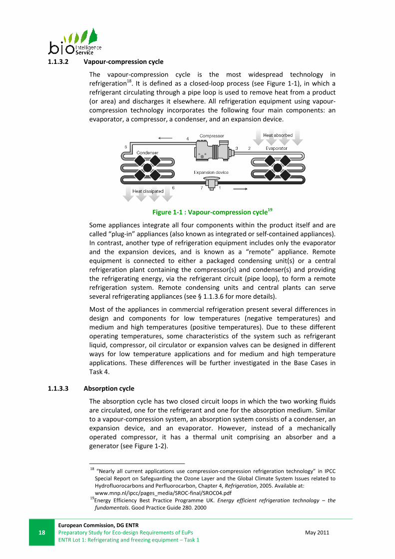
1.1.3.2 Vapour-compression cycle
The vapour-compression cycle is the most widespread technology in
refrigeration18. It is defined as a closed-loop process (see Figure 1-1), in which a
refrigerant circulating through a pipe loop is used to remove heat from a product
(or area) and discharges it elsewhere. All refrigeration equipment using vapour-
compression technology incorporates the following four main components: an
evaporator, a compressor, a condenser, and an expansion device.
Figure 1-1 : Vapour-compression cycle19
Some appliances integrate all four components within the product itself and are
called “plug-in” appliances (also known as integrated or self-contained appliances).
In contrast, another type of refrigeration equipment includes only the evaporator
and the expansion devices, and is known as a “remote” appliance. Remote
equipment is connected to either a packaged condensing unit(s) or a central
refrigeration plant containing the compressor(s) and condenser(s) and providing
the refrigerating energy, via the refrigerant circuit (pipe loop), to form a remote
refrigeration system. Remote condensing units and central plants can serve
several refrigerating appliances (see § 1.1.3.6 for more details).
Most of the appliances in commercial refrigeration present several differences in
design and components for low temperatures (negative temperatures) and
medium and high temperatures (positive temperatures). Due to these different
operating temperatures, some characteristics of the system such as refrigerant
liquid, compressor, oil circulator or expansion valves can be designed in different
ways for low temperature applications and for medium and high temperature
applications. These differences will be further investigated in the Base Cases in
Task 4.
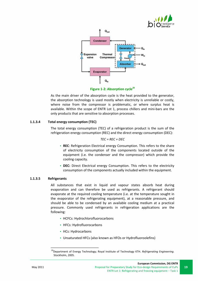
1.1.3.3 Absorption cycle
The absorption cycle has two closed circuit loops in which the two working fluids
are circulated, one for the refrigerant and one for the absorption medium. Similar
to a vapour-compression system, an absorption system consists of a condenser, an
expansion device, and an evaporator. However, instead of a mechanically
operated compressor, it has a thermal unit comprising an absorber and a
generator (see Figure 1-2).
18
“Nearly all current applications use compression-compression refrigeration technology” in IPCC
Special Report on Safeguarding the Ozone Layer and the Global Climate System Issues related to
Hydrofluorocarbons and Perfluorocarbon, Chapter 4, Refrigeration, 2005. Available at:
www.mnp.nl/ipcc/pages_media/SROC-final/SROC04.pdf 19
Energy Efficiency Best Practice Programme UK. Energy efficient refrigeration technology – the
fundamentals. Good Practice Guide 280. 2000
May 2011
European Commission, DG ENTR
Proposal for Preparatory Study for Eco-design Requirements of EuPs
ENTR Lot 1: Refrigerating and freezing equipment – Task 1
19
Figure 1-2: Absorption cycle20
As the main driver of the absorption cycle is the heat provided to the generator,
the absorption technology is used mostly when electricity is unreliable or costly,
where noise from the compressor is problematic, or where surplus heat is
available. Within the scope of ENTR Lot 1, process chillers and mini-bars are the
only products that are sensitive to absorption processes.
1.1.3.4 Total energy consumption (TEC)
The total energy consumption (TEC) of a refrigeration product is the sum of the
refrigeration energy consumption (REC) and the direct energy consumption (DEC):
TEC = REC + DEC
• REC: Refrigeration Electrical energy Consumption. This refers to the share
of electricity consumption of the components located outside of the
equipment (i.e. the condenser and the compressor) which provide the
cooling capacity.
• DEC: Direct Electrical energy Consumption. This refers to the electricity
consumption of the components actually included within the equipment.
1.1.3.5 Refrigerants
All substances that exist in liquid and vapour states absorb heat during
evaporation and can therefore be used as refrigerants. A refrigerant should
evaporate at the required cooling temperature (i.e. at the temperature sought in
the evaporator of the refrigerating equipment), at a reasonable pressure, and
should be able to be condensed by an available cooling medium at a practical
pressure. Commonly used refrigerants in refrigeration applications are the
following:
• HCFCs: Hydrochlorofluorocarbons
• HFCs: Hydrofluorocarbons
• HCs: Hydrocarbons
• Unsaturated HFCs (also known as HFOs or Hydrofluoroolefins)
20
Department of Energy Technology; Royal Institute of Technology KTH. Refrigerating Engineering.
Stockholm, 2005.

20
European Commission, DG ENTR
Preparatory Study for Eco-design Requirements of EuPs
ENTR Lot 1: Refrigerating and freezing equipment – Task 1
May 2011
• NH3: Ammonia
• CO2: Carbon dioxide
Refrigerants have widely varying properties and impacts and, due to the significant
environmental impact of certain refrigerant types, can be heavily regulated during
manufacture, use and disposal. Refrigerants will be assessed in detail in Task 4,
covering the above issues, as well as their performance and environmental impact.
1.1.3.6 Refrigeration systems
As described in § 1.1.3.2, a remote refrigeration system consists of remote
refrigerating equipment connected either to packaged condensing unit(s) or to a
central plant, via the refrigerant circuit.
Refrigeration system components can have a great impact on the performance of
refrigeration products, and many have specific standards, tests and specifications
to ensure their own quality and performance.
Four main configurations exist for remote refrigeration systems:
• direct expansion system;
• indirect expansion system or secondary refrigerant loop;
• distributed system;
• cascade system with two superposed refrigerant cycles.
Absorption based central refrigeration systems are less common, but in principle
similar configurations are possible. The only difference would be that the
compressor of the vapour-compression cycle is then replaced by the absorber and
generator of the absorption cycle.
A technical annex to this report, based on literature review and stakeholder
consultation, describes the various remote vapour-compression refrigeration
systems, analyses their market, and assesses their respective environmental
impacts, energy consumption and potential for improvement.
1.1.3.7 Efficiency measurement
The efficiency or performance of refrigeration systems indicators are normally the
relation between the energy input and the cooling capacity (output) or unit of
internal storage volume. The units commonly used are21:
• Coefficient Of Performance (COP): defined as the cooling capacity
divided by the energy input to the compressor, where higher
numbers indicate more efficient equipment. This number does not
have a unit of measurement.
• Energy Efficiency Ratio (EER): this value is defined as the ratio of
net cooling capacity (Btu/h22) to the total electricity input watt hour
(Wh). Higher values indicate more efficient equipment.
21
Source: www.engineeringtoolbox.com/cop-eer-d_409.html
22 1 BTU/h = 2.931x10
-4 kW

May 2011
European Commission, DG ENTR
Proposal for Preparatory Study for Eco-design Requirements of EuPs
ENTR Lot 1: Refrigerating and freezing equipment – Task 1
21
• Energy Efficiency Index (EEI): used to compare performance of
service cabinets per unit of storage volume, this is calculated from
the total energy consumption per 48 hours, divided by the net
internal volume of the product (kWh/48hrs/m3).
• The performance of equipment can be also evaluated by the ratio
of energy consumption aggregated over a period of time with a
characteristic dimension of the equipment or physical capacity
(volume) (m3, litre, and kg).
1.1.3.8 Insulation properties
The thermal transmission, or thermal resistance, properties of insulating
components can be described using the following factors:
• Lambda (λ) – thermal conductivity. This represents the thermal
transmission through a fixed thickness of a material, in W per
metre, considering a one degree temperature difference across the
material (λ = W/m.K). In the US, it is known as the "K factor”. In the
EU producers must declare the aged value, or λdesign (also termed
“lambda 90/90”). As ageing has a detrimental impact on insulation
material, the aged λ value will be greater than direct λ value.
• U value - thermal transmittance. This represents the thermal
transmission through a unit of surface area, in W per square metre,
considering a one degree temperature difference across the
material (U = W/m2.K).
� In the context of buildings it can also represent the overall
heat transfer coefficient (an averaged thermal
conductance in W/m2.K), and the terminology used in this
context can be the “K value”. In testing of mobile
refrigeration, the terminology used for this factor is “K
coefficient” (an averaged thermal transmission for the
insulating box in W/m2.K) (§1.14. ).
• R value – thermal resistance value. This represents the thermal
resistance of a material, and is the inverse of the thermal
conductivity, λ, multiplied by the thickness (R = m2.K/W). The
conversion between SI and US units of R-value is 1 h.ft².°F/Btu =
0.176110 K.m²/W.

22
European Commission, DG ENTR
Preparatory Study for Eco-design Requirements of EuPs
ENTR Lot 1: Refrigerating and freezing equipment – Task 1
May 2011
1.2. PRODUCT DEFINITIONS
This section aims to define the terminology for the products covered in ENTR Lot
1. Firstly, detailed information is provided on the technical description and precise
definition for each product category. An initial classification of products is based
on their function. This also includes a discussion23 of the technical features (such as
components and design) which play a significant role in the energy consumption
and other life-cycle environmental impacts caused by different products.
PRODCOM definitions related to commercial refrigeration appliances are then
described to evaluate whether or not the product classifications match the
database categories, and hence if this information can be added to the market
analysis.
1.2.1. SERVICE CABINETS
1.2.1.1 General product definition
Professional service cabinets are designed for the storage, but not the sale, of
chilled and frozen foodstuff. A professional service cabinet is a refrigerated
enclosure (with a gross internal volume of around 100 to 2 000 litres24) containing
goods which are accessible via one or more doors and/or drawers. The sizes of the
products are typically based on the Gastronorm standard (see §1.3.6.1) and are
used in a commercial environment.
“Commercial” refrigerators and freezers are related to the supermarket sector,
whereas “professional” refrigerators and freezers are related to a different
market: restaurants, hospitals, canteens, supermarket (i.e. locations not in direct
contact with the public). The main difference is not related to installation
environment, but to the user: a “commercial” refrigerator is used by a customer,
and will display produce, while a “professional” refrigerator is used by trained
staff, and will store the produce before use. Hence the terminology “professional”
is inferred when discussing service cabinets in ENTR Lot 1. Frequently existing
definitions refer to “commercial” service cabinets, when in fact “professional” use
of the products is relevant, therefore it is noted that terminology varies for
identical products.
1.2.1.2 Existing product definitions
Below is a list of definitions provided by existing schemes.
� UK ECA
Professional service cabinets have been defined under the ECA scheme Energy
Technology List (ETL) as “products that are specifically designed to store, but not
23
Such technical analysis will be further detailed in the subsequent Tasks (4-6) for products
prioritised in Task 1.4 24
Gross internal volume should be differentiated from net (internal) volume – gross volume is is
defined as the volume within the inside walls of the cabinet without internal fittings and with all
doors (and drawers) closed, while net volume is measured using different methodologies, defined
with test standards. Please see §1.3.1.7 for further details.

May 2011
European Commission, DG ENTR
Proposal for Preparatory Study for Eco-design Requirements of EuPs
ENTR Lot 1: Refrigerating and freezing equipment – Task 1
23
to display, chilled and frozen foodstuffs”,however, they are referred to as
“commercial”. The scheme covers three categories of product, as described below.
Table 1-1: UK ECA product categories
Type Gross internal volume (litres)*
Single door commercial service cabinets 400 and 600 (+/- 15%)
Double door commercial service
cabinets 1,300 (+/- 15%)
Under counter and counter commercial
service cabinets with solid doors or
drawers
150 to 800 (+/- 15%)
*Gross internal volume is defined as the volume within the inside walls of the cabinet without
internal fittings and with all doors (and drawers) closed.
To be considered under the scheme, service cabinets must also fulfil the following
criteria:
• they are designed to store chilled or frozen foodstuffs, whilst maintaining
them within prescribed temperature limits;
• they are fitted with solid-faced lids, drawers or doors that:
o are normally kept closed, but can be opened to access the
contents;
o obscure the contents of the cabinet from view when closed;
o enable users to access the contents of any part of the interior
without stepping into the refrigerated space; and
• they are a “plug-in” type cabinet with an integral refrigeration system (as
opposed to “remote” equipment with remotely located condensing unit).
The UK ECA scheme does not include remote type refrigerated service cabinet or
display cabinets, or cabinets with transparent doors, even if designed for storage.
� US Energy Star
The Energy Star energy efficiency scheme defines a service cabinet as a
“refrigerator, freezer, or refrigerator-freezer for storing food products or other
perishable items at specified temperatures and designed for use by commercial or
institutional facilities.”25 Although the standard refers to “commercial” use, due to
the fact that it refers to storage of foodstuff and solid doors, rather than display
and transparent doors, the products are in fact intended for professional use.
This scheme distinguishes products on the basis of operating temperature and
cabinet design.
On the basis of operating temperature, a “refrigerator” is defined as a cabinet
designed for storing items between 0°C and +4°C and a “freezer” refers to a
cabinet designed for storing items below 0°C. A “refrigerator-freezer” is defined as
a cabinet comprising more than one compartment, at least one of which is a
refrigerator and at least one of which is a freezer.
25
US Energy Star program requirements for commercial sold door refrigerators and freezers:
www.energystar.gov/index.cfm?fuseaction=find_a_product.showProductGroup&pgw_code=CRF

24
European Commission, DG ENTR
Preparatory Study for Eco-design Requirements of EuPs
ENTR Lot 1: Refrigerating and freezing equipment – Task 1
May 2011
These products can then be classified on the basis of cabinet design:
• reach-in: an upright commercial, self-contained refrigeration cabinet with
hinged, solid doors.
• horizontal: an upright commercial, self-contained refrigeration cabinet with
or without a worktop surface which has hinged, solid doors.
• roll-in or roll-through cabinet: an upright, self-contained commercial
refrigeration cabinet with hinged, solid doors that allows wheeled racks of
products to be rolled into or through the refrigerator or freezer.
• pass-through cabinet: an upright commercial, self-contained refrigeration
cabinet with hinged, solid doors on both the front and rear of the
refrigerator or freezer.
That said, the Energy Star scheme does not differentiate minimum performance
standards by these categories.
The scheme differentiates by size, operation temperature and product orientation
(vertical and chest), and includes remote type refrigerated service cabinets only.
1.2.1.3 Product description
Service cabinets are closed cabinets designed for the storage of foodstuffs and
that have at least one door, drawer or lid. Different configurations are available on
the market and some are shown in Figure 1-3. They are largely used in food-
service establishments, such as restaurants, hotels and cafeterias. A very small
fraction of “professional” service cabinets contain glass in their doors, drawers or
lids (as opposed to “commercial” service cabinets that display food and hence
frequently incorporate glass)26.
If the operation temperature is below 0°C, the unit is called a freezing service
cabinet, whereas when operation temperature is equal to or above 0°C the unit is
known as a refrigerated service cabinet. Some service cabinets may have a design
in which there are two or more compartments operating at different
temperatures, one above 0°C and the second one at temperatures below 0°C.
Analysis based on major EU manufacturers’ catalogue data, existing definitions
presented above, and previous studies on commercial refrigeration, shows that
the majority of service cabinets rely on compression technology (approximately
99%) and are mostly plug-in appliances (approximately 98%): i.e. all components
supporting the refrigeration cycle are included in the cabinet27. More detailed data
on the market composition is provided in Task 2.
26 Source: Foster
27 Source : replies to the 1st ENTR Lot 1 stakeholder questionnaire

May 2011
European Commission, DG ENTR
Proposal for Preparatory Study for Eco-design Requirements of EuPs
ENTR Lot 1: Refrigerating and freezing equipment – Task 1
25
Figure 1-3: Configurations of service cabinets
The majority of the market is for chilled or frozen upright cabinets with one or two
doors (between 400 and 600 litres for single door cabinets and 1,300 litres for
double door cabinets) or horizontal units with up to four doors (150 to 800 litres).
According to stakeholder feedback and product technical specifications, the
energy consumption for service cabinets varies depending on their function and
size, but an average product of 600 litres gross might consume 2000 kWh per
year28, while a freezer service cabinet of the same internal volume could consume
approximately double to triple this figure. Stakeholders stated that the dominant
model is an upright plug-in refrigerator, of approximately 600 litres.
Table 1-2: Specifications of service cabinets
Configuration Operation
temperature
Number of doors
/ drawers / lids
Approx. net volume,
V (litres)*
Vertical
Refrigerator 1 400 < V < 700
2+ 700 < V < 1500
Freezer 1 400 < V < 700
2+ 700 < V < 1500
Horizontal Refrigerator 1+ 150 < V < 800
Freezer 1+ 150 < V < 800
Chest Freezer 1+ 300 < V < 800
*Measured according to EN 441
The size of this equipment is often based on the Gastronorm standard sizes (see §
1.2.1.3).
1.2.1.4 Functional unit and performance parameter
The function of a service cabinet is to maintain products contained inside the
refrigerated space at a temperature below a pre-determined maximum, under
specific conditions (climate classes). The energy consumption under these
28
Source: Electrolux

26
European Commission, DG ENTR
Preparatory Study for Eco-design Requirements of EuPs
ENTR Lot 1: Refrigerating and freezing equipment – Task 1
May 2011
conditions is measured then this value is related to the internal net volume of the
machine (energy efficiency index).
The functional unit for service cabinets is a unit of storage volume (litres),
maintained at a specified temperature. The primary performance parameter is
defined as the electricity consumption per unit of storage volume in
kWh/litres/year.
1.2.1.5 Service cabinet classification and scope for the study
A classification is proposed for service cabinets to be included in the scope of the
study and is illustrated below.
Service
cabinets 1
Refrigerators
Freezers
Vertical
Horizontal
Open-top
preparation
counter2
Refrigerator-
freezers
Vertical
Horizontal
Chest 3
Vertical
Horizontal
2-door (or more)4
1-door4
as for vertical refrigerators
out of
scope
as for vertical refrigerators
as for horizontal
refrigerators
as for horizontal
refrigerators
2-door (or more)4
1-door4
1 – Professional products, either plug-in or remote
2 – Also known as ‘saladettes’, this product configuration is not included in the scope of ENTR Lot 1
due to different functionality
3 – Freezers and 1-door only
4 – Or with a combination of drawers
Figure 1-4: Service cabinet classification
This is based on stakeholder feedback and the similarities in definitions specified in
the product description summaries above (UK ECA29
and US Energy Star). Both
remote (although rare) and plug-in service cabinets are included in the scope of the
present study.
Some stakeholders stated that the scope of the product group covered should
exclude equipment with glass doors, drawers or lids, and that almost all
“professional” service cabinets have only solid doors (glass doors for “commercial”
service cabinets are covered in TREN Lot 12, but not those in “professional” service
cabinets). With the recent distinction in terminology in ENTR Lot 1 between
“professional” and “commercial” service cabinets, the exclusion from ENTR Lot 1 of
29
Source: ECA Energy technology criteria list 2009 – Refrigeration equipment. Commercial service
cabinets. 2009

May 2011
European Commission, DG ENTR
Proposal for Preparatory Study for Eco-design Requirements of EuPs
ENTR Lot 1: Refrigerating and freezing equipment – Task 1
27
“professional” service cabinets with glass doors, drawers or lids could create a
loophole in regulation.
Open-top preparation tables are considered out of scope, as they are usually
distinguished as a different product in standards definitions, and stakeholders
commented that their functionality (they have openings in the product shell to cool
storage trays, provide short-term storage and have frequent door openings – they
are also often not based on Gastronorm sizes) varies from service cabinets (which is
sealed equipment, providing longer-term storage and with fewer door openings). In
addition, they often include features that can impair refrigeration efficiency, e.g.
they can offer a base for the end-user to add a char-grill, griddle or grilling top30.
The following table describes some of the main differentiating criteria related to the
product group, which may impact on energy consumption.
Table 1-3: Specifications of service cabinets
Categorisations Explanation Notes
Operation
Temperature
Differentiating technical and
refrigerant requirements at low
freezing and high/medium
refrigeration temperature
Temperature will influence energy
consumption, which will be higher
for freezing compared to
refrigeration
Climate class
The climate class reflects the ambient
conditions, which can influence the
choice of the refrigerant, as well as
the performance
-
Volume
Fairly standard sizes, with some
variability, based around modular
units
Size ranges linked to configuration
Evidence that relationship with
energy efficiency is non-linear
Configuration
Vertical, horizontal, chest
Reach-in, roll-in and pass-through
options
Preparation counters
Open service counters such as pizza
preparation tables with refrigeration
units may be considered for
exclusion due different functionality.
Location of
condensing unit
Plug-in, remote condensing unit or
remote central plant
Influences ambient temperature -
climate zones (air-on temperature)
northern/southern EU relevant for
remote
Remote type very rare
Number of doors Can be a variety of combinations,
usually based around modular units. -
Door type Solid or transparent Transparent covered in TREN Lot 12
as display cabinets
Drawers Some horizontal include drawers,
based around modular units
Door-type model could be used as a
proxy for calculating energy
consumption
Condenser type Water, air, evaporative
Stakeholder feedback has
determined that most of the market
is air cooled
Refrigerant
The choice of refrigerant depends on
the operation temperature, ambient
temperature, refrigeration system
type
The most commonly used
refrigerants are R134a and R404a
Glass Rarely used Although rarely used, glass has a
much greater U-value, hence its use
30
Source: Foster Refrigeration

28
European Commission, DG ENTR
Preparatory Study for Eco-design Requirements of EuPs
ENTR Lot 1: Refrigerating and freezing equipment – Task 1
May 2011
will increase thermal infiltration and
increase heat load on the
refrigeration system
1.2.2. BLAST CABINETS
1.2.2.1 General product definition
Blast cabinets use a blast of cold air to bring down the temperature of hot food
rapidly so it can be stored safely avoiding bacteria growth, and can be chilled or
frozen.
1.2.2.2 Existing product definitions
� California Energy Commission (CEC)
According to CEC Appliance efficiency Regulations31 (CEC-400-2009-013), blast
cabinets, otherwise named blast chillers, are defined as machines that are able to
decrease foodstuff’s temperature from +140°F to +40°F (+60°C to +4°C) within 4
hours. However, the regulation does not go into further detail for this definition
since this kind of appliance is not included within its scope.
� FR AC D 40-003
The Equipment for collective restaurant – refrigerating equipment. General design
and construction rules for ensuring hygiene in use defines blast equipment as
appliances which are used to rapidly decrease the temperature of foodstuff below
+10°C in the case of chilling and below -18°C in the case of freezing. They exist in
different configurations, only chilling, only freezing and a combination of the two.
1.2.2.3 Product description
Blast cabinets are similar in construction to service cabinets. However, they rely on
relatively larger refrigeration systems in comparison to service cabinets, some even
using up to two compressors per cabinet. Blast cabinets also contain additional fans
which blast cold air over food to cool it rapidly. A typical blast refrigerator is shown
below in Figure 1-5. Under the scope of this study, blast walk-in rooms and
continuous-process blast equipment will not be included. For both machine types,
the use patterns differ from those of blast cabinets.
31
Source: California Energy Commission. 2009 Appliance Efficiency Regulations. CEC-400-2009-013.
2009

May 2011
European Commission, DG ENTR
Proposal for Preparatory Study for Eco-design Requirements of EuPs
ENTR Lot 1: Refrigerating and freezing equipment – Task 1
29
Figure 1-5: Typical blast refrigerator/freezer
In the market, there exist other configurations of blast equipment. These are
referred to as pass-through and trolleys units. In this case, cars or trolleys are used
to organise the foodstuff before it goes into the equipment. The capacity of this
equipment is higher, but, as was mentioned by stakeholders, their efficiency is
lower because of their need to cool down the trolley itself, among other reasons.
Glass-door equipment has not been identified in industry catalogues.
All fresh food products contain a natural bacterial load which, under favourable
ambient conditions (temperature and humidity), multiplies, increasing the risk of
illness and cross contamination with other food. The most dangerous temperature
range occurs between +35°C and +65°. Blast cabinets are designed to lower the
temperature at the centre of the pre-cooked food product as quickly as possible,
to avoid prolonging the period at which food temperature is within this range. This
not only prevents bacterial load from reaching dangerous levels, it also prolongs
the shelf-life of the product. Energy efficiency is therefore not often a priority for
the average product.32
The increase of energy consumption is not linear with the capacity. For larger sizes
of equipment, more non-foodstuff material will require cooling as well, and hence,
the efficiency decreases. An approximate relation between size and energy
consumption is shown in the table below.
Table 1-4: Energy consumption per equipment capacity for chilling and freezing
cycle reach-in (R) configuration33
Size Number of
trays (GN 1/1)
Average food
stuff capacity
(kg)
Approximate
energy
consumption
(kWh/chilling
cycle)
Approximate
energy
consumption
(kWh/freezing
cycle)
Small R 1-3 3-9 1 - 2 1.5-4
Medium R 5-10 15-30 1 - 4 5.5
Large R 12-15 36-45 2 - 5 5.5-11
Extra-large R > 16 > 48 > 6 > 9
Note: average capacity per GN 1/1 tray: 3-3.5kg of foodstuff
The size of equipment trays is normally determined according to Gastronorm
standard sizes (see § 1.2.1.3). It is estimated that each GN 1/1 tray has a capacity
of 3 to 3.5kg of foodstuff (as referred in NF AC D40-003, see $ 1.3.6.5).
The size classification for trolley using equipment (roll-in and pass-through) is
given in Table 1-5 below.
Table 1-5: Size description of trolley (T) equipment (roll-in and pass-through)
Size Number of trays
(GN 1/1) Trolleys
Average food stuff
capacity (kg)
32
Based on brochures and direct feedback of stakeholders
33 Stakeholders feedback

30
European Commission, DG ENTR
Preparatory Study for Eco-design Requirements of EuPs
ENTR Lot 1: Refrigerating and freezing equipment – Task 1
May 2011
Small T 10 – 30 1 – 3 30 – 90
Medium T 90 – 50 4 – 5 91 – 150
Large T 60 – 80 6 – 8 151 – 240
Testing of blast cabinets has limitations regarding the amount of food that has to
be cooked and heated. Stakeholders stated that a limitation of 60kg of foodstuff as
maximum quantity to be processed and tested. Limitations are related to the
cooling process itself and costs of the process.
1.2.2.4 Functional unit and performance parameter
The functional unit for blast cabinets can be defined as one kg of food (referred to
in this case as the testing material specified in NF AC D 40-003) cooled in a specific
cycle (kg/cycle) occupying a specific volume; the cycle defining the temperature
change and duration of cooling.
The use of mashed potatoes as referred in NF AC D 40-033 would overcome the
problems of heat resistance typical of other measurement loads, as stated by
stakeholders. Also, the reason why considering only the mixture of mashed
potatoes is to harmonize the material, as other foodstuff specific heat capacity can
change the results.
The performance of blast cabinets can therefore be defined as the net weight of
foodstuff that the cabinet can cool down at a certain temperature within a certain
period of time in certain conditions (e.g. ambient conditions, operating
conditions). The primary performance parameter can therefore be defined as the
electricity consumption per unit of foodstuff (referred to the testing material as
per NF AC D 40-003) refrigerated/frozen weight in kWh/kg within the fixed cooling
or freezing cycle.
Typical operating cycles include34:
• Cooling cycle: 90mins to 110mins for a specified mass of food (normally
the manufacturer’s declared unit capacity) with starting temperatures
ranging from +60°C to +90°C and finishing temperatures ranging from
+2°C to +10°C, satisfying European food safety standards and regulations.
• Freezing cycle: 240mins for a specified mass of food (normally the
manufacturer’s declared unit capacity) with starting temperatures ranging
from +60°C to +90°C and finishing temperatures ranging from -10°C to -
20°C, satisfying European food safety standards and regulations.
• Many appliances will sound an alarm to signal that the cooling/freezing
cycle has finished and then continue to maintain the final temperature for
the food, essentially operating then as a service cabinet until the operator
removes the food.
These appliances are available both in plug-in and remote configurations.
For plug-in blast refrigerators/freezers, the electricity consumption is
straightforward to assess: it is the total amount of electricity consumed by the
appliance.
34
Figures based on product technical specifications and existing product definitions

May 2011
European Commission, DG ENTR
Proposal for Preparatory Study for Eco-design Requirements of EuPs
ENTR Lot 1: Refrigerating and freezing equipment – Task 1
31
Remote blast refrigerators/freezers (i.e. units where the compressor and the
condenser are located outside the appliance) operate within a broader system.
Therefore, the following should be distinguished:
• the electricity consumption of the remote blast cabinet itself (containing
only the evaporator and the expansion device);
• the electricity consumption arising from the remote system (condensing
unit and piping system), to which the blast cabinet is connected, and
which delivers the refrigerating energy. This remote system may serve
several refrigerating appliances.
Currently there is no standardised way of calculating the electricity consumption
of remote blast cooling devices. However, the ISO 23953 related to remote display
cabinets can provide insights for developing a possible method.
In the ISO 23953 standard on refrigerated display cabinets, the energy
consumption is given by the total energy consumption in kilowatt hours per 24-
hour period (TEC). The means to calculate TEC for remote refrigerated display
cabinets is discussed in § 1.2.1.4.
1.2.2.5 Blast cabinets’ classification and scope for the study
This section provides a classification for blast cabinets to be included in the scope
of the study. Blast cabinets are produced according to the final operation
temperature required and the time to reach this requirement and the capacity of
food (by weight) that they can cool in this time35 as well as the overall orientation
of the product (reach-in, roll-in and pass-through).
Freezers 2
Refrigerators 2
Refrigerator /
freezers 2
Blast
cabinets
Plug-in
Remote
as above
as below
Capacity3
Roll-in/trolleys1
Cabinets/reach-in
Pass-through as above
as below
1 – Small Roll-in equipment is can be found in Plug-in configuration (normally up to 60kg or 90kg),
bigger units in remote configuration
2 – For large equipments (from around 60kg or 90kg) remote configuration represents 90% of sales
3 – Lower capacities correspond to reach-in equipment, being from 3kg to 100kg. Pass-though and
roll-in equipment capacity varies from around 30kg to 240kg (described in Table 1-4 and Table 1-5)
Figure 1-6: Blast cabinet classification
Figure 1-6 illustrates the categorisation for blast cabinets including the main
energy influencing parameters. Blast cabinets are characterised first by the
structure of the equipment (roll-in, cabinet or pass-through), then by the
35
Source: www.hennypenny.com/

32
European Commission, DG ENTR
Preparatory Study for Eco-design Requirements of EuPs
ENTR Lot 1: Refrigerating and freezing equipment – Task 1
May 2011
operation temperature (chiller, freezer or chiller-freezer), and finally by capacity
(kg, m3, etc). If required, they can also be characterised by the location of the
condensing unit in the arrangement (plug-in or remote – either packaged remote
or connected to a central plant).
Table 1-6: Specifications of blast cabinets Categorisations Explanation Notes
Capacity
Technical specification and energy will
depend on the capacity of the
equipment. It can vary from 3kg to 100kg
in the case of reach-in equipment or from
30kg to 240kg in the case of trolley
equipment
Since safety requirements
demand a specific target
temperature in a specific time,
the unit will consume more or
less energy according to the load
Larger equipment is less
common in the market
Configuration Roll-in equipment and pass-through are
typically larger appliances than reach-in
Roll-in and pass-through energy
efficiency is generally lower than
reach-in. However this is
compensated by the fact that
most trolley equipment is
remote
Operation
temperature
European equipment is typically used in
for a chilling function. Its energy
consumption is lower than equipment in
freezing operation
Freezing equipment has almost been
phased-out in some markets, but is still in
production in others.
Chilling/freezing (combination models).
Several stakeholders estimate that this
equipment is rarely used in freezing
cycles; however, their energy
consumption is similar to a freezer in this
function
Energy consumption testing will
be influenced by the ambient
conditions, and the functioning
of the equipment
Arrangement to be considered
within the testing methodology
Climate class
The climate class reflects the ambient
conditions, which can influence the
choice of the refrigerant, and the
performance as well
Two main climate zones could be
distinguished in the EU-27:
around +11°C for northern
Europe and around +15°C for
southern Europe
Location of
condensing unit
Plug-in, equipment with integral
condensing unit
Remote, connected to a central plant or
exterior condensing unit.
Influences ambient temperature
- climate zones (air-on
temperature) northern/southern
EU relevant for remote
Condenser type Water (rarely found), air, evaporative
(rarely found)
Stakeholder feedback has
determined that most of the
market is air-cooled
Refrigerant
The choice of refrigerant depends on the
operation temperature, ambient
temperature, refrigeration system type
The most commonly used
refrigerants is R404a
Both remote condensing and plug-in blast cabinets are included in the scope of the
present study. While stakeholder estimates predict that a great majority (85%) of
the market is dedicated to plug-in blast cabinets, remote condensing units are still
considered a subcategory of blast cabinets in this study.

May 2011
European Commission, DG ENTR
Proposal for Preparatory Study for Eco-design Requirements of EuPs
ENTR Lot 1: Refrigerating and freezing equipment – Task 1
33
Typically, blast cabinets are sold to consumers according to the final operating
temperature required, the time to reach this requirement and the capacity of food
(by weight) that they can cool in this time36.
Classification beyond these parameters could be done by type of condensing
coolant used (water, air, evaporative), however stakeholder feedback has
determined that this is not relevant as most of the market is air cooled.
1.2.3. WALK-IN COLD ROOMS
1.2.3.1 General product definition
According to the definition provided in the International Dictionary of
Refrigeration, a cold room is a room or cabinet maintained by a refrigerating
system at a temperature lower than ambient temperature. Walk-in cold rooms are
insulated rooms that provide refrigerated storage for a variety of items (mainly
foodstuff, but also flowers, etc.). They may exist as refrigerators or freezers. Walk-
in cold rooms with both a refrigerating and freezing compartment are normally
referred to as “dual compartment” and have two separate refrigeration systems.
1.2.3.2 Existing product definitions
� UK Defra
According to the UK Defra, a walk-in cold room is defined as follows:
“A walk-in cold store is an insulated enclosure with similar operational principles to
any refrigerator, but capable of storing significantly more goods. Generally, they
are fabricated on site and are a customised product, although the prefabricate
market is growing in size. Refrigeration is delivered through a forced-air
evaporator located in the cooled space, coupled to a condensing unit located
externally”.
� EU EOTA
The EOTA’s definition, presented in the European Technical Approval (ETA) and
implemented by the European Technical Approval Guidelines 021 (ETAG 021) for
cold rooms covers prefabricated cold storage room kits and cold storage building
enclosure and building kits. According to ETA, kits within the scope are those
constructed with insulating panels (sandwich type with insulation core) designed
to perform store products at temperatures from below +15°C to above -40°C.
Under appropriate maintenance a walk-in cold room kit should last 10 years.
� US DOE
The US statutory definition of walk-in coolers and freezers:
“The terms “walk-in cooler‘ and “walk-in freezer’ mean an enclosed storage space
refrigerated to temperatures, respectively, above, and at or below 32 degrees
Fahrenheit [0°C] that can be walked into, and has a total chilled storage area of
less than 3,000 square feet.” [(42 U.S.C. 6311(20)(A))]
The definition excludes:
36
Source: www.hennypenny.com/

34
European Commission, DG ENTR
Preparatory Study for Eco-design Requirements of EuPs
ENTR Lot 1: Refrigerating and freezing equipment – Task 1
May 2011
“products designed and marketed exclusively for medical, scientific, or research
purposes.” [(42 U.S.C. 6311(20)(B))]
� US CEC
CEC through the 2009 Appliance Energy Regulation37 (CEC-400-2009-013)
establishes the definition for walk-in coolers and walk-in freezers, differentiating
units with and without transparent, doors as follows:
“Walk-in coolers means an enclosed storage space refrigerated to temperatures
above 32°F [0°C] that can be walked into and has a total chilled storage area than
3 000 square feet. Walk-in coolers do not include products designed and marketed
exclusively for medical, scientific, or research purposes. Walk-in freezer means an
enclosed storage space refrigerated to temperatures at or below 32°F [0°C] that
can be walked into and has a total chilled storage area of less than 3 000 square
feet. Walk-in freezer does not include products designed and marketed exclusively
for medical, scientific, or research purposes”.
� Natural Resources Canada
Natural Resource Canada Office of Energy Efficiency defines walk-in cold rooms as:
“Walk-in refrigerators and freezers commonly used in fast-food and other
restaurants, institutional kitchens, convenience stores and other businesses are
room-sized insulated compartments, typically between 7 and 23m2 of floor area,
2.4m high, and refrigerated by a self-contained system. Much larger refrigerated
rooms are used in large supermarkets and food processing and packaging plants,
but these are usually supplied by large central refrigeration systems.”38
It therefore only considers plug-in walk-in cold rooms.
1.2.3.3 Product description
Walk-in cold rooms have at least one door that is large enough to allow a person
to go inside the insulated compartment. The main purpose of walk-in cold rooms is
for temporary storage of refrigerated or frozen perishable products. They are
widely used in restaurants, hotels, convenience stores, food wholesalers, florists
and warehouses.
Walk-in cold rooms can either be located indoors (i.e. constructed within a
building as part of that building) or outdoors (fabricated as a stand-alone structure
or an extension of an existing building). For external installations weather-proofing
must be considered, such as resistance to: wind load, snow load, rain, direct
sunlight, effect of potentially corrosive atmospheres, among others.
A typical walk-in cold room consists of following elements:
• an insulated enclosure, the refrigerated storage space being accessible via
an insulated door;
• a condensing unit located external to the refrigerated storage space;
37
California Energy Commission. 2009 Appliance Energy Regulation. CEC-400-2009-013, August
2009. 38
Natural resources Canada, Office of Energy Efficiency. Available at:
ttp://oee.nrcan.gc.ca/industrial/equipment/commercial-refrigeration/index.cfm?attr=24

May 2011
European Commission, DG ENTR
Proposal for Preparatory Study for Eco-design Requirements of EuPs
ENTR Lot 1: Refrigerating and freezing equipment – Task 1
35
• an evaporator fan-coil located within the refrigerated storage space
(usually situated near the ceiling in the room), which may or may not be
integrated with the condensing unit; and
• a system of pipes and controls to allow the refrigeration circuit to cool the
storage space.
The insulated enclosures are constructed from self supporting, pre-fabricated,
insulation panels. These panels are made of two steel skins that are injected with
high pressure, often polyurethane, foam.
Analysis based on major EU manufacturers’ catalogue data, existing definitions39,
and previous studies40 on commercial refrigeration shows that walk-in cold rooms
use vapour-compression technology. Further, walk-in cold room refrigeration
systems (condensing unit plus evaporator unit) can be found in different
configurations.
• Remote refrigeration systems: evaporator coil within the insulated box,
connected to a condensing unit located remotely (i.e. condensing unit
located outdoors). Products can also be connected to a central
refrigeration system where the condensing unit serves many different
refrigerating appliances (e.g. in supermarkets where cooling energy is
provided by a refrigeration plant to several appliances including not only
the cold room but also, for example, display cabinets) - see Figure 1-7.
Figure 1-7: Typical walk-in cold room and major components41
• Packaged refrigeration systems : include all required elements (evaporator
fan-coil, condensing unit, and piping) and are either integrated or
attached (such as the “monoblock” type) to the walk-in cold room
insulated box, forming part of the product (see Figure 1-8).
39
Source: UK Enhanced Capital Allowance scheme, US Energy Star Program 40
Arthur D. Little Inc, Energy Savings Potential for Commercial Refrigeration Equipment, US DOE,
1996 and Mark Ellis & Associates, Self-Contained Commercial Refrigeration, Australian Greenhouse
Office, 2000 and Mark Ellis & Associates, Remote Commercial Refrigeration, Australian Greenhouse
Office, 2000 41
Natural resources Canada, Office of Energy Efficiency. Available at:
http://oee.nrcan.gc.ca/industrial/equipment/commercial-refrigeration/index.cfm?attr=24

36
European Commission, DG ENTR
Preparatory Study for Eco-design Requirements of EuPs
ENTR Lot 1: Refrigerating and freezing equipment – Task 1
May 2011
Figure 1-8: Typical Walk-in cold room with packaged refrigeration system
If the operation temperature is below 0°C, the unit is called a walk-in freezer,
whereas if the operation temperature is equal to or above 0°C the unit is known as
a walk-in refrigerator. Some walk-in cold rooms may have a design in which there
are two compartments operating at different temperatures, one above 0°C and
the second one at temperatures below 0°C.
Estimates of walk-in cold rooms integrating glass windows and/or doors sold in the
EU range from 1 to 5% of the market42. These can include in-store products with
one or more sides facing the store for display and providing direct rear access to
display cases within the store.
There is a lack of data describing typical electricity consumption of walk-in cold
rooms, but indicative figures of 14,600kWh/year for a 48.31m3 walk-in
refrigerator, and 15,600 kWh/year for a 13.4m3 walk-in freezers43, have been
identified.
1.2.3.4 Functional unit and performance parameter
The function of walk-in cold rooms is to store a certain volume of foodstuff at a
desired temperature. The functional unit for walk-in cold rooms can be defined as
a unit of internal volume maintained at a specified temperature, for a specific
period of time, in specific ambient conditions.
The functional unit for walk-in cold rooms is a unit of net internal volume (m3),
maintained at a specified temperature. The primary performance parameter is
defined as the electricity consumption per unit of net internal volume in
kWh/m3/year.
Electricity consumption for plug-in units is straightforward to assess. In the case of
remote units connected to a refrigeration system, energy consumption could be
assessed as explained for service cabinets.
1.2.3.5 Walk-in cold rooms’ classification and scope for the study
Apart from the distinctions drawn in §1.2.3.3 on the operation temperature and
refrigeration system type, other examples of potential classification are now
considered. Various operation temperature ranges for different applications are
described in Table 1-7.
42
Source: Smeva, GR Scott 43
US Department of Energy, 2009 US DoE. Available at:
www1.eere.energy.gov/buildings/appliance_standards/commercial/pdfs/wicf_framework_publicmt
g_slides.pdf
May 2011
European Commission, DG ENTR
Proposal for Preparatory Study for Eco-design Requirements of EuPs
ENTR Lot 1: Refrigerating and freezing equipment – Task 1
37
Table 1-7: Walk-in cold rooms application temperature ranges44
Type of equipment Operation temperature
(°C) Main use
Cellar rooms +10 to +12 Beer cooling, food
preparation area
General purposes +1 to +4 Generic foodstuff storage
Meat rooms -2 to +2 Meat storage
Deep freeze -22 to -18
Ice cream storage and
other deep-frozen
foodstuff
An alternative classification classification for walk-in cold rooms based on the size
of the equipment is described in Table 1-8.
Table 1-8: Walk-in cold rooms categorisation45
Equipment type Size (m3)
Storage
temperature
Average COSP
Small < 20 Refrigeration 1.84
Freezing 1.32
Medium 20 < 100 Refrigeration 2.41
Freezing 1.47
Large 100 < 400 Refrigeration 2.66
Freezing 1.47
COSP: Coefficient of system performance
A third classification for walk-in cold rooms, based on the size of the room and
configuration of the refrigeration system, is described in Table 1-9.
Table 1-9: Walk-in cold rooms categorisation46
Equipment
type
Typical (attached refrigeration
system) equipment characteristics Size (m
3)
Nominal capacity
(W at +5°C)
Mini Packaged unit Plug-in
< 27 2,250
Small < 72 4,100
Medium Medium condensing
unit Remote
< 144 9,000
Large Centralised plant or
large condensing unit < 400 20,400
Larger walk-in cold rooms are typically bespoke projects constructed in-situ with
component parts from various sources to match the specifications of the end-user
(henceforth termed “customised”), while smaller rooms are typically constructed
from pre-fabricated insulated enclosures (henceforth termed “factory-built”).
The following classification, adapted from those above and informed by
stakeholder feedback, is proposed for walk-in cold rooms.
44
Source: Equipment installer 45
UK MTP estimates 46
Mark Ellis, Strategies to increase the energy efficiency of non-domestic refrigeration in Australia &
New Zealand, 2009

38
European Commission, DG ENTR
Preparatory Study for Eco-design Requirements of EuPs
ENTR Lot 1: Refrigerating and freezing equipment – Task 1
May 2011
Walk-in cold
rooms 1
High temperature
(Refrigerators)
Low temperature
(Freezers)
Factory-built3
Customised4
as above
Cold stores
Wander-in /
Logistics stores 2 out of scope
Dual compartment
(Refrigerator-freezers) as above
Integral
Monoblock
Remote
condensing unit
Remote central
plant
1 – Products up to 400m
3
2 – Cold stores above 400m3
in size, or those forming part of a building, or those as a stand-alone
external building, or those incorporating loading bays are not covered in ENTR Lot 1
3 – Products that are pre-designed and supplied in modular series
4 – Designed and constructed by specialist installers
Figure 1-9: Classification for walk-in cold rooms
There are three main options for the refrigeration system configuration: packaged,
remote condensing unit and remote central plant, as described in §1.2.3.3.
There are certain products that are excluded from the scope, including products
designed and marketed exclusively for medical, scientific, or research purposes;
due to tighter temperature control requirement they have a different
functionality, which will have an impact on testing and energy consumption. The
scope covers only “walk-in” products and not cold stores (which are more complex
constructions). Large systems over 400m2 are therefore excluded; there would be
smaller cold air spill from the product when its door is opened and there are likely
to be other heat loads such as vehicle loading bays. Those products incorporated
into a building are excluded (apart from cold storage building kits) as they are
already covered by existing regulations and are a not similar type of product.
The table below describes factors that are important in the consideration of
product design, functionality and performance.
Table 1-10: Specifications of walk-in cold rooms
Categorisations Explanation Notes
Size Small, medium and large products
At approximately 100m2, a loading dock might be
included in a walk in cold store – these have other
sources of heat that should be considered; rooms
with loading docks are considered out of the
scope due to different functionality
400m3 too big to be classified as ‘walk-in’ cold
rooms.
Construction Classification should note if the unit Rooms constructed as part of a building, or that

May 2011
European Commission, DG ENTR
Proposal for Preparatory Study for Eco-design Requirements of EuPs
ENTR Lot 1: Refrigerating and freezing equipment – Task 1
39
Categorisations Explanation Notes
is prefabricated or constructed as
part of the building
are over 2.5m in height are considered out of the
scope due to different functionality
Configuration
Packaged (refrigeration system
manufactured as a complete product
by manufacturer or integrated into
one of the panels) or customised
(designed individually)
Could differentiate between products testable
under a test standard, and those more complex
products that require a different regulatory
mechanism (i.e. unique field-erected designs)
Operation and
ambient
temperatures
Differentiating technical and
refrigerant requirements at low
freezing and high/medium
refrigerating temperature
The functioning temperature will influence the
heat load and energy consumption, which will be
higher for freezing compared to refrigeration
Climate class
The climate class reflects the ambient
conditions, which can influence the
choice of the refrigerant, as well as
the performance
Two main climate zones could be distinguished in
the EU-27: around +11°C for northern Europe and
around +15°C for southern Europe
Location of
condensing unit
Integrated as part of the insulated
enclosure, remote condensing unit or
remote central plant
Heat rejection process is different between
remote and plug-in configurations
System performance is influenced by the ambient
temperature - climate zones (air-on temperature)
northern/southern EU relevant for remote
Condenser cooling Air-cooled or water-cooled -
Application
Foodstuff / pharmaceutical
application;
Logistics and large industrial
applications vs. small retail and
storage uses
Equipment for pharmaceutical storage is similar
but has more narrowly controlled temperatures,
stability specifications and stricter build
specification (they use a double freezing system;
rooms with these more accurate/double
refrigeration systems are considered out of the
scope due to different functionality
Internal space
arrangement
The internal space arrangement can
vary according to requirement of the
customer
Affects performance through change of the
internal air flow
Insulation thickness This can range from 50mm to 180mm -
Condenser type Water, air, evaporative Stakeholder feedback has determined that most
of the market is air cooled
Refrigerant
The choice of refrigerant depends on
the operation temperature, ambient
temperature, refrigeration system
type
The most commonly used refrigerants is R404a

40
European Commission, DG ENTR
Preparatory Study for Eco-design Requirements of EuPs
ENTR Lot 1: Refrigerating and freezing equipment – Task 1
May 2011
1.2.4. PROCESS CHILLERS
1.2.4.1 General product definition
According to the International Dictionary of Refrigeration47, a chiller is a piece of
equipment designed to cool water for air-conditioning plants or units in
commercial and industrial processes.
In general, a chiller is a refrigerating machine that removes heat from a liquid
through a vapour compression or absorption cycle. Chillers can be used in a wide
range of applications48:
• Plastics: during plastics manufacturing, these equipments are used to cool
hot plastics being injected, blown, extruded or stamped, as well as the
equipment used during these processes.
• Injection moulding: while removing heat from a source – e.g. during
manufacture of plastic products – chillers can transfer heat to make the
processes more efficient moulding stage.
• Printing: chillers are able to remove the heat generated by the friction of
the rollers and for cooling down the paper after the ink drying process.
• Laser: chilling systems are used to cool down laser and power supplies in
the laser cutting and light projection industries.
• Rubber: during the different process of rubber production, temperature
control is very important; the use of chillers is common to control these
conditions.
• Air conditioning: commonly used in comfort appliances to remove heat
from buildings. These machines are considered within the upper operation
temperature range. Equipment working in this temperature range will not
be included in this preparatory study, instead they will be analysed within
the scope of ENTR Lot 6.
• Magnetic resonance imaging: chillers can remove heat from scanners if
necessary.
• Anodising: chillers are used to cooled down the water used in these
processes to increase the efficiency in warmer climates.
Refrigeration systems that remove heat from foodstuffs in order to preserve it can
beneficiate from chiller technology. The temperatures reached in these appliances
must meet requirements for food preservation.
1.2.4.2 Existing product definitions
� EUROVENT certification programme
The EUROVENT certification programme defines liquid chilling packaged as: “a
factory assembled unit, designed to cool liquid, using a compressor, an evaporator
and an integral or remote condenser and appropriate controls.” The certification
47
International Institute of Refrigeration. International Dictionary of Refrigeration. 2007 48
Source: www.1stchoicechillers.com/products.htm

May 2011
European Commission, DG ENTR
Proposal for Preparatory Study for Eco-design Requirements of EuPs
ENTR Lot 1: Refrigerating and freezing equipment – Task 1
41
programme applies to standard chillers used for air conditioning and for
refrigeration. They may operate with any type of compressor, but only electrically
driven chillers are included. All refrigerants are considered. Chillers may be air-
cooled, water cooled or evaporative cooled and with remote condenser. Reverse
cycle chillers are also included and certified both in cooling and in heating mode
(see § 1.4.10. ).
The UK Defra uses the same definition and specifies that “Packaged chillers are
commonly used in both central plant air-conditioning systems for the built
environment where typical applications include offices, retail, commercial and
public premises, and for other ‘process’ cooling applications including; food &
drink manufacturing, the chemical industry, plastics injection moulding and
engineering to name but a few.”
� UK ECA
The UK ECA scheme defines packaged water chiller functionality as:
“Packaged chillers generate chilled water that can be used to provide space
cooling in summer in large air-conditioned buildings. They can also be used to
generate chilled water or brine needed by industrial process cooling. Reversed
cycle packaged chillers are able to provide space heating in winter, as well as space
cooling”.
� US AHRI 550/590-2003
The AHRI 550/590-2003 standard for water-chilling packages using the vapour
compression cycle defines water chillers as follows:
“Water-Chilling Package is a factory-made and prefabricated assembly (not
necessarily shipped as one package) of one or more compressors, condensers and
evaporators, with interconnections and accessories, designed for the purpose of
cooling water. It is a machine specifically designed to make use of a vapour
compression refrigeration cycle to remove heat from water and reject the heat to
a cooling medium, usually air or water. The refrigerant Condenser may or may not
be an integral part of the package.”
It further defines a subcategory as follows:
“Heat Reclaim Water-Chilling Package is a factory-made package, designed for the
purpose of chilling water and containing a Condenser for reclaiming heat. Where
such equipment is provided in more than one assembly, the separate assemblies
are to be designed to be used together, and the requirements of rating outlined in
this standard are based upon the use of matched assemblies. It is a package
specifically designed to make use of the refrigerant cycle to remove heat from the
refrigerant and to reject the heat to another fluid (air or water) for heating use.
Any excess heat may be rejected to another medium, usually air or water”.
� US AHRI 560-2000
The ANSI/AHRI 560:2000 standard for rating absorption water chilling and water
heating packages defines absorption chillers as follows:
“Absorption Water Chilling and Water Heating Package Is a factory designed and
prefabricated assembly employing water as the refrigerant and consisting of an
evaporator, absorber, condenser, generator(s) and solution heat exchangers, with
interconnections and accessories used for chilling or heating water. The package

42
European Commission, DG ENTR
Preparatory Study for Eco-design Requirements of EuPs
ENTR Lot 1: Refrigerating and freezing equipment – Task 1
May 2011
utilises single or multiple reconcentrations of an absorbent solution. The
reconcentrations of the absorbent are known as effects. A single effect package
employs one step reconcentration of the absorbent in the generator. Water
vapour is released after the heat energy is introduced into the generator. The
concentrated absorbent is returned to the absorber where its double effect
package employs a two step reconcentration of the absorbent through the use of
an additional high temperature generator. An absorption package can be further
defined by the following:
• Direct Fired Package. This type of package reconcentrates the absorbent
from heat energy through the combustion of natural gas, LP gas or oil.
• Indirect Fired Package. This type of package reconcentrates the absorbent
from heat energy from steam or hot water.”
1.2.4.3 Product description
Chillers can be used both in industrial applications for refrigeration purposes and
in buildings for air-conditioning purposes. They comprise a refrigeration system
and are connected to a water (or water/glycol mix) circuit driven by a pump.
Chillers can be found either as packaged factory assembled units or can be field
erected assembly with different components. Both vapour-compression and
absorption refrigeration cycles are used. This can be explained by the fact that in
buildings or industrial processes, heat losses can occur which can be used to drive
the absorption based chillers, leading to significant electricity savings compared to
the use of a vapour-compression based chiller.
Chillers’ operation temperatures range from -25°C to +15°C, with 3 sub-
classifications retaken by EUROVENT Certification program and discussed with
stakeholders:
• high temperature chillers: leaving chilled water temperature between +2°C
and +15°C;
• medium temperature chillers: leaving brine temperature between -12°C
and +3°C; and
• low temperature chillers: leaving brine temperature between -25°C and -
8°C.
High temperature chillers are predominantly used for comfort cooling, and are
hence excluded from the scope of the study, while medium and low temperature
chillers are used for industrial process refrigeration applications and are
investigated. High operation temperature equipment will be considered under
the scope of ENTR Lot 6.
In order to reach low and medium temperatures, the water used in the chiller is
mixed with Ethylene glycol or propylene glycol. The efficiency of the equipment
will decrease with the increase of the concentration of this substance. Another
factor affecting the efficiency corresponds to the differential of temperature.
The choice of the type of technology depends mostly on the application range, as
described in Table 1-11.

May 2011
European Commission, DG ENTR
Proposal for Preparatory Study for Eco-design Requirements of EuPs
ENTR Lot 1: Refrigerating and freezing equipment – Task 1
43
Table 1-11: Technologies applied in chillers according to capacity range49
Cycle Technology
Typical Capacity
Range (kW)
(and tonne of
refrigeration)1
Typical Capacity
Range (kW)
(and tonne of
refrigeration)2
Typical Capacity
Range (kW)
(and tonne of
refrigeration)3
Vapour
Compression
Centrifugal
compressor
>200
(60) -
300 – 9,000
(85 – 2,600)
Screw compressor 200-1,500
(50-400)
100 – 1,900
(30 – 540)
100 – 1,900
(30 – 540)
Scroll compressor < 750
(215)
10 – 250
(3 – 70)
15 – 200
(4 – 50)
Reciprocating
compressor
75 – 500
(20 – 150) 0.5 – 200 -
Absorption > 15
(5) Non-applicable Non-applicable
1Relevant for air conditioning
2Relevant for refrigeration, air-cooled
3Relevant for refrigeration, water-cooled
-: Non-available data
� Process chillers
Process chillers for refrigeration are used in many different applications50 to
provide cold water and process refrigeration and can be either plug-in appliances
(packaged) or uniquely designed to meet customers’ specifications.
A single chiller cannot fit every temperature level requirement. Some chillers are
designed to cool to very low temperatures while others are designed for only mid-
range applications. Some designs can support very high flow rates of fluid and
others are designed for low rates of fluid. The same issues apply with ambient
temperatures. Some chillers use refrigerant suited for a high ambient temperature
environment while other refrigerants are formulated for cooler conditions.
Packaged chillers are factory-assembled refrigeration units that are designed to
cool liquid using a plug-in, electrically-driven mechanical vapour-compression
system or gas fired absorption system. Packaged chillers based on vapour
compression systems include the refrigeration compressor(s), controls (e.g.
temperature settings, etc.) and the evaporator in the packaged unit. The
condenser may also be integrated or remote, air-cooled or water-cooled (see
Figure 1-10). Some packaged chillers may also include a unit comprising a chilled
water (or water/glycol mix) buffer tank and a chilled water (or water/glycol mix)
circulation pump which constitutes the coolant circuit hardware (see Figure 1-11).
49
Alliance for Responsible Atmospheric Policy, Global Comparative Analysis of HFC and Alternative
Technologies for Refrigeration, Air Conditioning, Foam, Solvent, Aerosol Propellant, and Fire
Protection Applications, Final Report, March 21, 2002 50
E.g. Plastics & Rubber: presses, injection, moulding, extrusion, blow moulding, thermoforming,
PET; Lasers: cutting, welding, profiling, optics, medical, engraving; Food & Beverage: confectionary,
bakeries, distilleries, breweries, wineries, dairies, bottling, carbonation, meat and fish, processing,
vegetable and salad processing, storage; Chemical & Pharmaceutical: jacketed, vessels,
polyurethane foam mixers, natural gas, industrial cleaning, laboratories, healthcare, solvents,
paints, photo processing, oil cooling; Metal Working: processing and transformation of precious
metals, aluminium working and processing; Mechanical & Engineering: machine tools, welding
machines, rolling mills, presses, extruders, cutting, profiling, polishing, electric spark machinery,
hydraulic control unit oil, oiling, pneumatic transport, heat treatment; Paper & Related
Applications: printers, cardboard, labels, plastic film and other applications

44
European Commission, DG ENTR
Preparatory Study for Eco-design Requirements of EuPs
ENTR Lot 1: Refrigerating and freezing equipment – Task 1
May 2011
Packaged chillers without these two components of the coolant circuit integrated
are also known as “split” chillers” (see Figure 1-10).
These units deliver a cooling capacity ranging from 1.75kW to 700kW in the case of
packaged chillers with air-cooled condensers, and up to 7,050 kW in the case of
packaged chillers using a water-cooled condenser.
Figure 1-10: Existing configurations for packaged chillers51
Figure 1-11: Packaged chiller integrating the coolant circuit pump and tank52
Packaged absorption based chillers also exist which are driven by gas combustion.
Such products include a gas burner which serves as the heat source to drive the
generator.
51
UK Carbon Trust, Industrial refrigeration equipment, A guide to equipment eligible for Enhanced
Capital Allowances. 2009
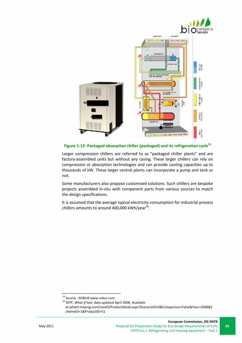
May 2011
European Commission, DG ENTR
Proposal for Preparatory Study for Eco-design Requirements of EuPs
ENTR Lot 1: Refrigerating and freezing equipment – Task 1
45
Figure 1-12: Packaged absorption chiller (packaged) and its refrigeration cycle53
Larger compression chillers are referred to as “packaged chiller plants” and are
factory-assembled units but without any casing. These larger chillers can rely on
compression or absorption technologies and can provide cooling capacities up to
thousands of kW. These larger central plants can incorporate a pump and tank or
not.
Some manufacturers also propose customised solutions. Such chillers are bespoke
projects assembled in-situ with component parts from various sources to match
the design specifications.
It is assumed that the average typical electricity consumption for industrial process
chillers amounts to around 400,000 kWh/year54.
53
Source : ROBUR www.robur.com 54
MTP, What If tool, data updated April 2008. Available
at:whatif.mtprog.com/Level3/ProductDetail.aspx?ScenarioID=0&Comparison=False&Year=2008&S
chemeID=1&ProductID=51
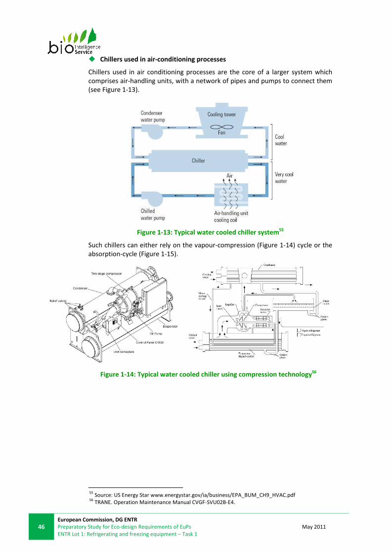
46
European Commission, DG ENTR
Preparatory Study for Eco-design Requirements of EuPs
ENTR Lot 1: Refrigerating and freezing equipment – Task 1
May 2011
� Chillers used in air-conditioning processes
Chillers used in air conditioning processes are the core of a larger system which
comprises air-handling units, with a network of pipes and pumps to connect them
(see Figure 1-13).
Figure 1-13: Typical water cooled chiller system55
Such chillers can either rely on the vapour-compression (Figure 1-14) cycle or the
absorption-cycle (Figure 1-15).
Figure 1-14: Typical water cooled chiller using compression technology56
55
Source: US Energy Star www.energystar.gov/ia/business/EPA_BUM_CH9_HVAC.pdf 56
TRANE. Operation Maintenance Manual CVGF-SVU02B-E4.

May 2011
European Commission, DG ENTR
Proposal for Preparatory Study for Eco-design Requirements of EuPs
ENTR Lot 1: Refrigerating and freezing equipment – Task 1
47
Figure 1-15: Typical water cooled chiller using absorption technology57
The variation of the efficiency according to the outlet temperature for an
equipment of the same capacity is shown in Table 1-12. The factor of variation was
provided by stakeholders and is only an approximation, as the same equipment is
not likely able to perform at extremely different temperature ranges.
Table 1-12: Change of the efficiency according to outlet temperature for
equipment of the same capacity, considering high temperature equipment as
base
Outlet temperature range
(°C)
Average outlet temperature
(°C)
Efficiency factor
+2 / +15 +7 X
-12 / +3 -5 0.7X
-25/-8 -15 0.5X
1.2.4.4 Functional unit and performance parameter
The primary function of a chiller is to cool down and maintain the temperature of
a liquid (e.g. water, water/glycol mix) to cool an environment, process or product
to an appropriate level of temperature. The functional unit is therefore the
cooling capacity, in kW, considering a reference ambient temperature at which
the measurement is done (+30°C for water-cooled equipment and +35°C for air-
cooled equipment)
The performance parameter of chillers is expressed using the COP58
, which is the
ratio between the cooling capacity and the power input.
The heating performance of chillers is also expressed using the COP which is the
ratio of the heating capacity (i.e. heat given off from the refrigerant to the liquid
being heated per unit of time in reverse cycle operation) to the power input of the
unit.
Chillers usually operate at full load only during a limited period of time during a
year. Therefore, the part load performance is much closer to reality. In the US, the
performance of chillers is expressed as the Integrated Part Load Value (IPLV) which
57
TRANE. Trane horizon Absorption Series. ABS-PRC0016EN 58
COP: Coefficient of Performance: ratio between cooling capacity and power input

48
European Commission, DG ENTR
Preparatory Study for Eco-design Requirements of EuPs
ENTR Lot 1: Refrigerating and freezing equipment – Task 1
May 2011
is the average power input based upon a chiller operating at part loads through a
cooling season.
In the EU, an index called ESEER – Seasonal energy efficiency ratio – is used. This
index is similar to IPLV and takes into account several parameters in order to
establish an average use of chillers throughout EU: weather data, building load
characteristics, operational hours etc. Stakeholders commented that this ratio was
soon to be replaced by the SEER, as mentioned in prEN 14825:2009.
1.2.4.5 Chiller classification and scope for the study
Chillers represent a very wide range of products, not only in terms of applications
but also technologies.
AHRI 550/590:2003 proposes a classification to water chillers depending on the
cooling medium (Water-cooled chillers, evaporatively-cooled and air-cooled),
while ANSI/AHRI 560 proposes a classification for absorption chillers based on the
technology (single stage indirect fired, two-stage indirect fired and two-stage
direct fired)
EUROVENT certification program presents classification of equipments depending
on the following parameters:
• heat rejection: water cooled or air cooled;
• system: packaged, split or remote condenser;
• operation type: cooling only or cooling/heating;
• duct: ducted or non-ducted;
• compressor type (centrifugal, screw, etc.)
The UK ECA scheme classifies packaged chillers according to their capacity related
to the technology implemented in the system. However, it only includes within the
scope vapour-compression units. It considers the following four groups59:
• air-cooled packaged chillers that only provide cooling and have a cooling
capacity that is less than or equal to 1,500kW;
• air-cooled, reverse cycle, packaged chillers that provide heating and cooling
and have a cooling capacity that is less than or equal to 750kW;
• water-cooled packaged chillers that only provide cooling and have a cooling
capacity that is less than or equal to 2,000kW; and
• water-cooled, reverse cycle, packaged chillers that provide heating and
cooling and have a cooling capacity that is less than or equal to 2,000kW.
The sub-classifications for the cooling capacity, related to EER and COP are shown
in Table 1-28.
59
ECA Energy Technology Criteria List 2009 – Refrigeration Equipment. Packaged Chillers
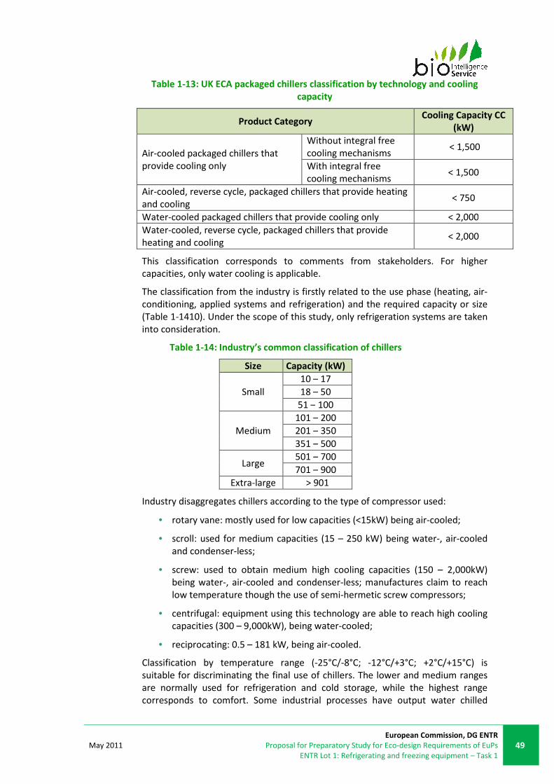
May 2011
European Commission, DG ENTR
Proposal for Preparatory Study for Eco-design Requirements of EuPs
ENTR Lot 1: Refrigerating and freezing equipment – Task 1
49
Table 1-13: UK ECA packaged chillers classification by technology and cooling
capacity
Product Category Cooling Capacity CC
(kW)
Air-cooled packaged chillers that
provide cooling only
Without integral free
cooling mechanisms < 1,500
With integral free
cooling mechanisms < 1,500
Air-cooled, reverse cycle, packaged chillers that provide heating
and cooling < 750
Water-cooled packaged chillers that provide cooling only < 2,000
Water-cooled, reverse cycle, packaged chillers that provide
heating and cooling < 2,000
This classification corresponds to comments from stakeholders. For higher
capacities, only water cooling is applicable.
The classification from the industry is firstly related to the use phase (heating, air-
conditioning, applied systems and refrigeration) and the required capacity or size
(Table 1-1410). Under the scope of this study, only refrigeration systems are taken
into consideration.
Table 1-14: Industry’s common classification of chillers
Size Capacity (kW)
Small
10 – 17
18 – 50
51 – 100
Medium
101 – 200
201 – 350
351 – 500
Large 501 – 700
701 – 900
Extra-large > 901
Industry disaggregates chillers according to the type of compressor used:
• rotary vane: mostly used for low capacities (<15kW) being air-cooled;
• scroll: used for medium capacities (15 – 250 kW) being water-, air-cooled
and condenser-less;
• screw: used to obtain medium high cooling capacities (150 – 2,000kW)
being water-, air-cooled and condenser-less; manufactures claim to reach
low temperature though the use of semi-hermetic screw compressors;
• centrifugal: equipment using this technology are able to reach high cooling
capacities (300 – 9,000kW), being water-cooled;
• reciprocating: 0.5 – 181 kW, being air-cooled.
Classification by temperature range (-25°C/-8°C; -12°C/+3°C; +2°C/+15°C) is
suitable for discriminating the final use of chillers. The lower and medium ranges
are normally used for refrigeration and cold storage, while the highest range
corresponds to comfort. Some industrial processes have output water chilled

50
European Commission, DG ENTR
Preparatory Study for Eco-design Requirements of EuPs
ENTR Lot 1: Refrigerating and freezing equipment – Task 1
May 2011
between +4°C and +6°C – these products might require specific performance
constraints different from air-conditioning equipment. Some stakeholders stated
that the power capacity and size are common classifications because they provide
with the necessary information about energy and working capacity (even if they
reach the same temperatures). The cooling system of each chiller is relevant as it
will have environmental consequences. Also, it is very important to take into
account the type of refrigerant for environmental reasons. However, the energy
performance of the equipment is more related to the configuration than the type
of refrigerant used60.
According to stakeholders, there is a size limitation for packaged chillers, having up
to 5MW of cooling capacity if it is water-cooled, and up to 1,500-1,800kW if it is
air-cooled (due to limitations regarding noise problems). Air cooled equipment is
also less energy efficient than water cooled ones61.
Chillers
…
…
High temp2
Low temp
Medium tempCapacity1
Air-cooled3
Water-cooled4
1 – Capacities to be from 15kW to 1000kW. The compressor type will be related to the capacity
required
2 – Low temperature: -25°C / -8°C. Medium temperature: -12°C / +3°C. High temperature: +2°C /
+15°C (not considered under the scope of ENTR Lot 1, therefore absorption chillers are not considered
in the scope of the study)
3 – Relevant specially for small capacity equipment
4 – Only relevant for big capacity equipment
Figure 1-16: Chiller classification
The following table describes some of the main differentiating criteria related to
the product group, which may impact energy consumption.
60
Mark Ellis consultation 2010. 61
Energy Efficiency Ratio (EER) - a ratio of the cooling capacity in Btu/h to the power input values in
watts at any given set of Rating Conditions expressed in Btu/(W·h)

May 2011
European Commission, DG ENTR
Proposal for Preparatory Study for Eco-design Requirements of EuPs
ENTR Lot 1: Refrigerating and freezing equipment – Task 1
51
Table 1-15: Specifications of process chillers Categorisations Explanation Notes
Configuration Field-erected or packaged
Comments from stakeholders
indicated that the configuration
of the equipment does not
significantly influence the energy
consumption (as long as it is
properly installed)
Operation
temperature High, medium or low
The efficiency of chillers
decrease for lower
temperatures.
Location of
condensing unit
Packaged equipment with integral
condensing unit
Remote, connected to a central plant or
exterior condensing unit
Influences ambient temperature
- climate zones (air-on
temperature) northern/southern
EU relevant for remote
Ambient
temperature
The ambient temperature can influence
the choice of the refrigerant, as well as
the performance
Two main climate zones could
be distinguished in the EU-27:
around +11°C for northern
Europe and around +15°C for
southern Europe
Cooling capacity
The compressor and system used
depends on the operating temperature
and the cooling capacity of the product.
For low cooling capacities, the
most used compressor is
hermetic reciprocating; while for
medium and high cooling
capacities the compressor can
be semi-hermetic reciprocating,
scroll or screw.
Large cooling capacities require
compressor packs and racks
Refrigeration
system Vapour compression or absorption -
Compressor type
There are different technologies
applicable to compressors:
• reciprocating (hermetic and semi-
hermetic);
• scroll ;
• rotary ;
• and screw
-
Condenser type Water, air, evaporative -
Refrigerant
The choice of refrigerant depends on the
operation temperature, ambient
temperature, refrigeration system type
-
Anti-freezing agent
Additive to avoid water freezing at lower
temperatures. Ethylene glycol, propylene
glycol and brine are typically used from
10% to 40% depending on the target
temperature.
-
Chillers covered in the study are those that operate at low and medium
temperature (see § 1.2.4.3) – those that are predominantly used for commercial
and industrial freezing or chilling – and chillers used for high temperature
applications are excluded (to be covered by ENTR Lot 6).
52
European Commission, DG ENTR
Preparatory Study for Eco-design Requirements of EuPs
ENTR Lot 1: Refrigerating and freezing equipment – Task 1
May 2011
1.2.5. REMOTE CONDENSING UNITS
1.2.5.1 General product definition
Remote condensing units are a classification of products which only comprise of
part of the refrigeration cycle: the compressor and the condenser. The evaporator
and expansion valve are components which, as supplied, are integrated in the cold
storage devices (cabinets, cold rooms, etc.) and are required to complete the
system.
There are typically three fundamental system arrangements:
• packaged condensing units (PCUs) with one or more compressors;
• non-packaged condensing units with independent compressor and
condenser;
• compressor packs or racks independent from the condenser.
PCUs are products which include one or more compressor(s) and condensing
equipment for cooling rooms or large spaces, such as cool storage rooms, or for
providing refrigeration service to other locations. Remote refrigerating appliances
(i.e. not plug-in appliances), including the products discussed above, can be
connected to the PCU.
PCUs are commonly installed in walk-in cold rooms in clubs, pubs, hotels, butchers
and other food preparation and service industries. They are also widely used in
supermarkets. In most of these places, additional refrigeration energy is provided
by self-contained central refrigeration units, however the large majority of
refrigeration energy is provided by PCUs62.
Non-packaged condensing units are independent compressors and condensers
that can be sold and installed separately and thus can be considered as a
customised cooling system.
Compressor packs are framed packages of up to ten compressors, the average is
three, with one or more remote condensers designed for commercial refrigeration
purposes. When compressor packs are used for industrial processes, they are
designed as compressor racks. These appliances are designed to be incorporated
into a refrigeration system and normally mounted indoors in mechanical rooms,
for large applications such as supermarkets. They require an external condensing
unit (or less commonly can have integrated water cooled condensers). A
compressor pack or rack is defined as an assembly of one or more compressors
complete with interconnecting pipe work. They may include liquid receivers, filter
driers, oil separators, shut-off valves and related controls, and are supplied on a
structurally rigid frame. Most packs are in the range 30 kW to 400 kW, reaching a
maximum of 900 kW. They are generally customised, adjusted and installed
according to the needs of the customer.
A typical compressor pack (commercial cooling) or rack (industrial cooling) is
factory assembled and incorporates at least the following components:
62
Analysis of Potential for Minimum Energy Performance Standards for Remote Commercial
Refrigeration, Mark Ellis & Associates, 2000

May 2011
European Commission, DG ENTR
Proposal for Preparatory Study for Eco-design Requirements of EuPs
ENTR Lot 1: Refrigerating and freezing equipment – Task 1
53
• one or more electrically driven refrigeration compressors; and
• a control system that controls the product’s compressor(s) and cooling
fan(s).
Non-packaged condensing units and compressor packs/racks, which operate
independently from the condenser, are not complete condensing units because
they do not have condensers integrated, but only compressors and controls. These
two parts are sold independently, and thus the performance is measured only on
the compressor or on the condenser fan motors. When the compressor is sold as
an independent product it is affected by the regulation EC 640/2009 for electric
motors.
For this reason, non packaged condensing units and compressor packs/racks are
not under the scope of this preparatory study and will not be further investigated.
1.2.5.2 Existing product definitions
A condensing unit is defined as an assembly of a condenser and one or more
compressors completed with interconnecting pipe work. They may include liquid
receivers, filter driers, oil separators, shut-off valves and related controls, as well
as a weatherproof housing63.
PCUs cover products that are specifically designed to provide cooling to other
equipment that incorporate evaporators (and associated expansion valve control
systems).
According to the International Dictionary of Refrigeration64, a condensing unit is an
assembly including a compressor with motor, a condenser, and a liquid receiver
when required.
In the EN 13215:2000 standard, condensing unit is defined as “combination of one
or more compressors, condensers or liquid receivers (when applicable) and the
regularly furnished accessories”.
In the EN 13771-2:2007 standard, a condensing unit is defined as a “factory
assembled unit comprised of refrigeration compressor and motor, condenser and
any necessary associated ancillaries”.
In the UK ECA Scheme certification programme, air cooled condensing units are
defined as “factory-assembled units that consist of an air-cooled condenser, one
or more compressors, and interconnecting pipe work. They may include liquid
receivers, filter driers, oil separators, shut off valves and related controls, and a
weatherproof housing”.
1.2.5.3 Product description
PCUs are factory-assembled, packaged units that consist of a refrigeration
compressor, a motor, a condenser, and various others components. This packaged
unit does not contain a complete refrigeration system, but is designed to provide a
cooling for a cold room or other equipment fitted with an evaporator that is
controlled by an expansion valve.
63
ECA Energy Technology Criteria List – Technology: Refrigeration Equipment, August 2004. 64
International Institute of Refrigeration. International Dictionary of Refrigeration. 2007
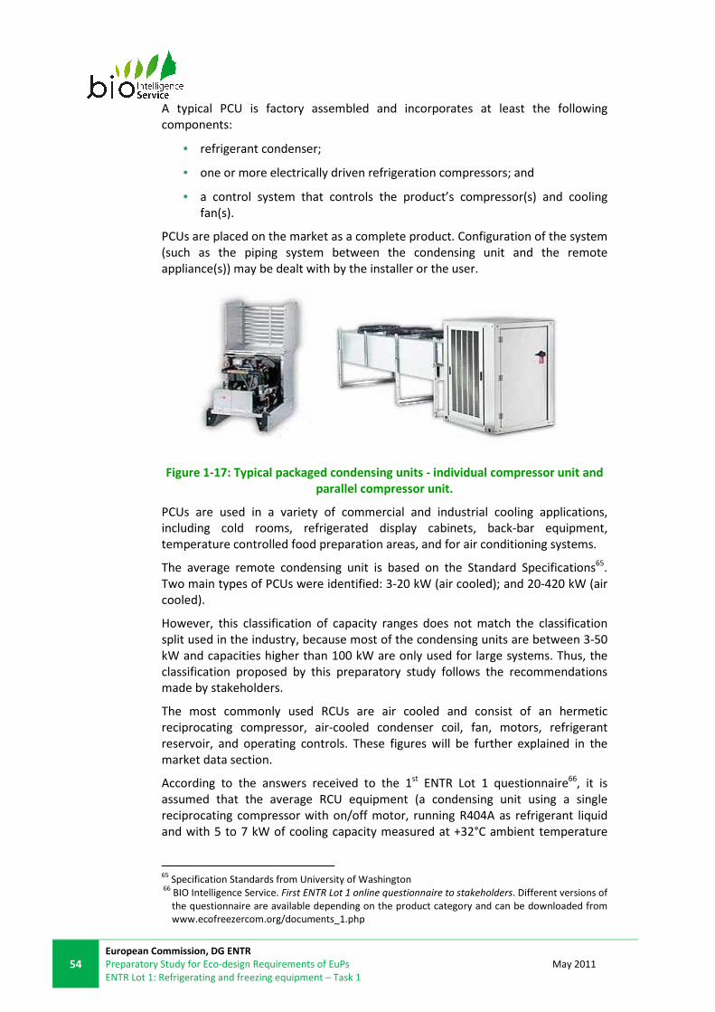
54
European Commission, DG ENTR
Preparatory Study for Eco-design Requirements of EuPs
ENTR Lot 1: Refrigerating and freezing equipment – Task 1
May 2011
A typical PCU is factory assembled and incorporates at least the following
components:
• refrigerant condenser;
• one or more electrically driven refrigeration compressors; and
• a control system that controls the product’s compressor(s) and cooling
fan(s).
PCUs are placed on the market as a complete product. Configuration of the system
(such as the piping system between the condensing unit and the remote
appliance(s)) may be dealt with by the installer or the user.
Figure 1-17: Typical packaged condensing units - individual compressor unit and
parallel compressor unit.
PCUs are used in a variety of commercial and industrial cooling applications,
including cold rooms, refrigerated display cabinets, back-bar equipment,
temperature controlled food preparation areas, and for air conditioning systems.
The average remote condensing unit is based on the Standard Specifications65.
Two main types of PCUs were identified: 3-20 kW (air cooled); and 20-420 kW (air
cooled).
However, this classification of capacity ranges does not match the classification
split used in the industry, because most of the condensing units are between 3-50
kW and capacities higher than 100 kW are only used for large systems. Thus, the
classification proposed by this preparatory study follows the recommendations
made by stakeholders.
The most commonly used RCUs are air cooled and consist of an hermetic
reciprocating compressor, air-cooled condenser coil, fan, motors, refrigerant
reservoir, and operating controls. These figures will be further explained in the
market data section.
According to the answers received to the 1st ENTR Lot 1 questionnaire66, it is
assumed that the average RCU equipment (a condensing unit using a single
reciprocating compressor with on/off motor, running R404A as refrigerant liquid
and with 5 to 7 kW of cooling capacity measured at +32°C ambient temperature
65
Specification Standards from University of Washington 66
BIO Intelligence Service. First ENTR Lot 1 online questionnaire to stakeholders. Different versions of
the questionnaire are available depending on the product category and can be downloaded from
www.ecofreezercom.org/documents_1.php

May 2011
European Commission, DG ENTR
Proposal for Preparatory Study for Eco-design Requirements of EuPs
ENTR Lot 1: Refrigerating and freezing equipment – Task 1
55
and +10°C evaporating temperature, with a condenser fan of 130W) consumes
around 20,000 kWh/year. This estimation varies depending on the ambient
temperature, evaporating temperature, refrigerant used, type of compressor and
fan, characteristics of the system and workload, leakage rate, etc.
1.2.5.4 Functional unit and performance parameter
The function of remote refrigeration systems is to provide refrigeration service to
other appliances. Therefore the way of calculating the electricity consumption of
the remote condensing units is using the REC, in kilowatt hours per 24-hour
period. This refers to the electricity consumption of the condenser and the
compressor which is used to provide cooling energy to the appliance. REC is based
on the input and output temperatures of the liquid refrigerant circulating in and
out of the remote product.
The remote condensing units work an average of 15-17 hours per day, 365 days
per year. These working hours are not continuous, and the length of each working
time depends on the needs of the system. The rest of the time the condensing unit
does not consume energy, according to information received from stakeholders.
The ambient temperature varies for the different countries in the EU, from an
average of +11°C in northern member states to +15°C in the southern member
states. However, the ambient temperature stated in the testing standard EN
13215:2000 is +32°C.
The functional unit identified for these equipments is kW of cooling capacity.
The proposed performance parameter is the coefficient of performance (COP58
).
1.2.5.5 Remote condensing units classification and scope for the study
A classification for RCUs included in the scope of the study is illustrated below in
Figure 1-18. This classification was developed with the industry and considers the
parameters typically used.
Categorisation of appliances begins with the layout of the refrigeration
components. Packaged condensing units with integrated compressors which are
intended to be mounted outside are one category, the next category being
packaged condensing units with multiple compressors. Compressor packs
requiring externally mounted condensers and independent compressors and
condensers do not fit the existing definitions of condensing units and are left out
of the scope of this study, as explained above. The packaged condensing units can
then be subcategorized by the evaporating temperature which determines the
capacity, size of compressor, energy consumption, etc. Finally the capacity of the
unit can help to classify the product. Other characteristics to further classify
remote condensing units are compressor type (reciprocating, scroll, screw or
rotary), compressor motor speed drive (on/off, two speeds, variable speed) and
condenser cooling (air or water cooled).

56
European Commission, DG ENTR
Preparatory Study for Eco-design Requirements of EuPs
ENTR Lot 1: Refrigerating and freezing equipment – Task 1
May 2011
Remote
condensing
units
Packaged with
single compressor
Packaged with
multiple
compressors
Medium temp.
High temp.
Low temp.1
Non packaged with
independent condenser
and compressor
Low capacity
Medium capacity
as above
High capacity2
out of
scopeIndependent compressor
packs
as above
out of scope
1 – High temperature: +5°C; Medium temperature: -10°C; Low temperature: -35°C
2 – High capacity: > 50kW; Medium capacity: 20kW-50kW; Low capacity: 0.2kW-20kW
Figure 1-18: Remote condensing unit classification
Condensing units for high evaporating temperature (+5°C) are used in air
conditioning systems whereas, in commercial refrigeration, only medium (-10°C)
and low (-35°C) temperatures are used. As the scope of this preparatory study is
commercial refrigeration, and air conditioning products are covered in ENER Lot 6
preparatory study (air conditioning and ventilations systems), condensing units for
high temperatures are left out of the scope of the present preparatory study and
will not be further investigated. However, some of the appliances designed for
medium temperature can work at high temperature and vice-versa. The aim of this
preparatory study is to inform the later discussion and consultation process which
may lead to regulation the performance of the remote condensing units working
on commercial refrigeration temperatures, even though the products affected can
be used for other purposes. The share of the market that this kind of appliance
represents is not taken into account in the various calculations.
The following table describes some of the main differentiating criteria related to
the product group, which may impact energy consumption.

May 2011
European Commission, DG ENTR
Proposal for Preparatory Study for Eco-design Requirements of EuPs
ENTR Lot 1: Refrigerating and freezing equipment – Task 1
57
Table 1-16: Specifications of condensing units Categorisations Explanation Notes
Configuration
The condensing units can be
designed and sold as:
• packaged with single
compressor(compressor and
condenser on the same plate);
• packaged with twin
compressors or more
• compressor packs or racks
• independent compressor and
condenser
Packaged and independent
configurations can be sold as
independent products by the
industry
Both packaged units and
independent systems can use up to
10 compressors in order to obtain
higher cooling capacities and
efficiencies.
Evaporating
temperature
Evaporating temperatures in food
conservation applications are driven
by legislation: frozen foodstuff must
be under -18°C (LT).
• Low evaporation temp.: -35°C
• Medium evaporation
temperature: -10°C
• High evaporation temp.: +5°C
The operating temperature
determines the appropriate
refrigerant and required cooling
capacity.
Cooling capacity
The compressor and system used
depends on the operating
temperature and the cooling
capacity of the product.
For low cooling capacities, the most
used compressor is hermetic
reciprocating; while for medium
and high cooling capacities the
compressor can be semi-hermetic
reciprocating or scroll. Screw
compressors are used in larger
cooling capacities and mostly for air
conditioning. Extra large cooling
capacities require compressor
racks.
Compressor type
There are different technologies
applicable to compressors:
• reciprocating (hermetic and
semi-hermetic)
• scroll
• screw
• rotary
The most used compressor is
reciprocating hermetic
Compressor motor
drive
The compressor motor can be
driven with different technologies:
• on/off
• 2-speed
• variable speed drive
In partial load conditions, 2 speed
and variable speed drive can
achieve higher efficiencies than
on/off compressors, but under full
load conditions the on/off
technology is more efficient.
Condenser type Water cooled, air cooled.
Stakeholder feedback has
determined that most of the
market is air cooled.
Refrigerant
The choice of refrigerant depends
on the operation temperature,
ambient temperature, refrigeration
system type.
The most commonly used
refrigerant is R404a.
Ambient
temperature
The ambient temperature can
influence the choice of the
refrigerant, as well as the
performance of the condensing
unit.
Two main climate zones can be
distinguished in the EU-27: around
+11°C for northern Europe and
around +15°C for southern Europe
EN 13215:2000 standard
establishes +32°C as standard
temperature for testing; UK ECA
Scheme establishes MEPS for +20°C
ambient temperature.

58
European Commission, DG ENTR
Preparatory Study for Eco-design Requirements of EuPs
ENTR Lot 1: Refrigerating and freezing equipment – Task 1
May 2011
Categorisations Explanation Notes
Location The location of the condensing unit
can impact its performance.
Should be placed in a well
ventilated area, away from direct
sunlight.
Only packaged condensing units are included in the scope of the present study.
The manner in which these products interact with the system they operate under
is very important for the overall efficiency of the system and therefore must be
analysed from an ecodesign perspective.
1.2.6. PRODCOM DEFINITIONS
In order to better identify the types of equipment that can be considered as
refrigeration and freezing equipment, existing product classifications used by
PRODCOM67 are identified. PRODCOM classifies commercial refrigerators and
freezers in the category NACE 29.23 – “Manufacture of non-domestic cooling and
ventilation equipment”. In its subcategories different types of refrigerating
appliances are listed, which are presented in Table 1-17.
Table 1-17: PRODCOM classification of commercial refrigeration equipment
PRODCOM code PRODCOM category
29.23.13 Refrigerating and freezing equipment and heat pumps, except
household type equipment
29.23.13.33 Refrigerated show-cases and counters incorporating a refrigerating unit
or evaporator for frozen food storage
29.23.13.35 Refrigerated show-cases and counters incorporating a refrigerating unit
or evaporator (except for frozen food storage)
29.23.13.40 Deep-freezing refrigerating furniture (except for chest freezers of a
capacity ≤ 800 litres, upright freezers of a capacity ≤ 900 litres)
29.23.13.50 Refrigerating furniture (except for deep-freezing, show-cases and
counters incorporating a refrigerating unit or evaporator)
29.23.13.73 Compression type units whose condensers are heat exchangers, heat
pumps
29.23.13.75 Absorption heat pumps
29.23.13.90 Other refrigerating or freezing equipment
It can be observed that commercial refrigeration appliances appear in this
classification explicitly. However, apart from the capacity and the temperature,
few criteria are used to distinguish between different types of products (e.g. no
differentiation between plug-in and remote appliances).
As some of the equipment of the commercial refrigeration sector is technically
similar to domestic refrigeration equipment (e.g. service cabinets), the table below
provides PRODCOM references for household-type refrigerators and freezers.
67
PRODCOM Classification: List of Products of the European Union

May 2011
European Commission, DG ENTR
Proposal for Preparatory Study for Eco-design Requirements of EuPs
ENTR Lot 1: Refrigerating and freezing equipment – Task 1
59
Table 1-18: PRODCOM classification of household refrigeration equipment
PRODCOM code PRODCOM category
29.71.11 Refrigerators and freezers, of the household type
29.71.11.10 Combined refrigerators and freezers, with separate external doors
29.71.11.33 Household type refrigerators (including compression-type, electrical
absorption type, excluding built-in)
29.71.11.35 Compression-type, built-in
29.71.11.50 Chest freezers of capacity ≤ 800 litres
29.71.11.70 Upright freezers of a capacity ≤ 900 litres

60
European Commission, DG ENTR
Preparatory Study for Eco-design Requirements of EuPs
ENTR Lot 1: Refrigerating and freezing equipment – Task 1
May 2011
1.3. PRODUCT TEST STANDARDS, THEIR DEVELOPMENT AND OTHER
STANDARDS
The aims of this section are to give an overview of existing product standards,
standards under development and associated test methods, to identify gaps, and
to highlight needs for forums to discuss development of standards and creation of
new standards. Please also see annex 1-2 for other standards related to the
product groups.
A “testing standard” is a standard that sets out a test method but does not
indicate what result is required when performing that test. Therefore, strictly
speaking, a testing standard is different from a “technical standard”. In technical
use, a standard is a concrete example of an item or a specification against which all
others may be measured or tested. Often it indicates a required performance level
to be achieved in order to comply with the standard. Testing standards are also
(but not exclusively) defined in the technical standard itself. For example, an ISO
standard for a product or process gives detailed technical specifications, which are
required in order to conform to that standard. It also defines testing methods to
be followed for validating such conformity. A standard can be either product- or
sector-specific, and it can concern various stages of a product’s life cycle.
The main focus in this subtask is on environmental performance and related
technical aspects (e.g. energy consumption and resource consumption) in relation
to functional performance. However, for the sake of completeness, other
standards (such as health and safety-related standards) related to refrigeration
equipment are also considered.
Test methods and standards exist for nearly all components used within
refrigeration equipment and are presented in Annex 1-1.
It is important to note that for product performance testing, different testing
methodologies can lead to significant variations in test results for the same
product, and that frequently for refrigeration there are requirements concerning
limits to temperature fluctuations within the refrigerated space that relate to food
safety. Therefore, although some standard performance parameter figures quoted
in the literature may seem comparatively low, it is not always stated what
standard methodology these figures have been measured under, and whether the
product satisfies the food safety requirements.
1.3.1. SERVICE CABINETS
Historically EN 441 has been the standard methodology for testing of service
cabinets. It has been proposed that a new standard be developed for professional
service cabinets in the EU, based on EN ISO 23953, and this process is being driven
by EFCEM68. This development has been slightly confused due to the different
technical committees that are responsible for safety and performance of these
products. TC59/61/E-C is relevant to safety, whereas TC59X is relevant to
performance. Stakeholders estimated that the variation in results of performance
testing can be 5 to 10% between EN 441 and EN ISO 23953 when evaluating the
68
Source: EFCEM, ENTR Lot 1 3rd
stakeholder meeting

May 2011
European Commission, DG ENTR
Proposal for Preparatory Study for Eco-design Requirements of EuPs
ENTR Lot 1: Refrigerating and freezing equipment – Task 1
61
same product69. The differences between these two test methodologies are
compared in §1.3.1.7 and §1.3.1.8.
1.3.1.1 EN ISO 23953:2005 (under revision)
Relevance: Service cabinets, possible adaptability for blast cabinets
EN ISO 23953:2005 “Refrigerated display cabinets – Vocabulary, Classification,
requirements and test conditions” (replacing former EN 441:1995) is used for
energy consumption measurement of commercial refrigerated display cabinets for
the sale and/or display of food products. In principle this standard can be used for
measuring the energy performance of service cabinets as well.
Scope: This standard does not cover service cabinets intended for use in catering
or similar non-retail appliances, minibars, ice-makers, ice cream machines,
milkshake machines and cold rooms. However, this standard could be used for
performance calculation of professional service cabinets (for example, former
version EN 441:1995 is used as a reference testing method in the framework of the
UK ECA for commercial service cabinets).
The test for closed refrigerated cabinets should always be carried out on a
complete cabinet, regardless of the number of doors or lids. The requirements
state that the cabinet lighting should be switched on for a period of 12 h; followed
by 12 h with the cabinet lighting switched off. With the night covers removed,
leave the cabinet lighting switched on for a period of 12 h; followed by 12 h with
the night covers on and the cabinet lighting switched off.
Start 0 - 12 hours 12 – 24 hours
3 min open (2) each door or lid opened 6 times
per hour for 6 seconds(3)
each door closed
(2)Where a cabinet is provided with more than one door or lid, each door or lid
shall be opened for 3 min consecutively.
(3)Door open at an angle of greater than 60° for 4 s. If the cabinet has multiple
doors, the doors are opened in sequence within each 10-min period — where
there are two doors, for example, open door no. 1 at 0 min, door no. 2 at 5 min,
door no. 1 at 10 min, door no. 2 at 15 min, and so on.
� Revisions
EFCEM and CECED Italia, in partnership with European manufacturers, are
currently adapting EN ISO 23953:2005 for testing of professional service cabinets.
The main changes are in the procedure used to evaluate the units, as the door
openings required in the current version for commercial cabinets are considered
as not representative of the typical use pattern for professional service cabinets.
Recommended alterations include the following aspects.
• For calculation of net volume, where n is the number of shelves: Shelf or
drawer base area x (loading height – n x thickness of shelf). Please see
§1.3.1.7 for further discussion on measurement of internal storage
volume.
69
Source: ARNEG

62
European Commission, DG ENTR
Preparatory Study for Eco-design Requirements of EuPs
ENTR Lot 1: Refrigerating and freezing equipment – Task 1
May 2011
• Test packages70 have to follow air circulation direction. For temperature
monitoring: as described in the picture below (§Figure 1-19), this should
be carried out with one probe on the left, one in the centre and one on
the right.
Figure 1-19: Packages arrangement during temperature monitoring.
• Changes proposed to the timings of door/lid openings;.
Procedure: during the 24 hours, consumption measurements should be recorded
as follows.
Freezing
Start 0 - 4 hours 4 – 8
hours
8 hours 8 – 12 hours 12 – 24
hours
1 min
open
each door opened
6 times per hour
for 6 seconds(4)
each
door
closed
1 min
open
each door opened
6 times per hour
for 6 seconds(4)
each
door
closed
Refrigeration
Start 0 – 12 hours 12 – 24 hours
2 min open cycle each door opened 6 times per hour
for 6 seconds(4)
each door closed
(4)Where more than one door or lid pertains to the cabinet to be tested, the
sequence in which the doors and lids are opened shall be staggered.
One issue to note concerns the terminology used in EN ISO 23953. ENTR Lot 1 uses
the term “horizontal” to define the orientation of the product. However, within EN
ISO 23953, “horizontal” is a term used to describe the display area orientation
(Part 1, Annex A). This potentially confusing terminology should be revised or
clarified.
70
Manufactured gel (cellulose) with specific constrains to test service cabinets according to different
standards. In some cases, thermocouple temperature sensors can be inserted into this device.
www.frperc.bris.ac.uk/home/restopcs/frigtest.htm. 2010

May 2011
European Commission, DG ENTR
Proposal for Preparatory Study for Eco-design Requirements of EuPs
ENTR Lot 1: Refrigerating and freezing equipment – Task 1
63
1.3.1.2 EN 441:1995
Relevance: Service cabinets
EN 441, “Refrigerated display cabinets. General mechanical and physical
requirements”, has been used as a standard to measure performance of service
cabinets. It is composed of several parts providing terms, definitions, mechanical
and physical requirements, dimensions, general tests, a temperature test, a
classification according to temperature, a defrosting test, a water vapour
condensation test, electrical energy consumption, a test for absence of odour and
taste, an installation and user’s guide, and measurement of the heat extraction
rate of the cabinets when the condensing unit is remote from the cabinet.
Although this standard has been withdrawn, it is still in use.
In Part 1 of the standard, the net volume definition is described: Volume
containing food products within the load limit. Parts necessary for the proper
functioning of the cabinet, including shelves used in the calculation of refrigerated
shelf area, are fitted as intended and the volume representing the space occupied
by these parts is deducted from the gross volume when the net volume is
determined.
In Part 3 (Linear dimensions, areas and volumes), it states:
• Physical dimensions - the manufacturer shall for each cabinet state
nominal data, including net volume, according to the definitions given in
EN 441-1. Measurements shall be made with the cabinet not in operation
but situated in ambient conditions corresponding to the climate class (see
EN 441-4) for which it is intended.
• Tolerances - the area and volume values required in 3.1 (Physical
dimensions) and calculated according to the definitions given in EN 441-1
shall not be less than 97% of the stated values.
• Test report – this should clearly state, amongst others, the net volume for
each temperature class declared and the volumes shall be expressed in
litres without decimal or cubic metres (to three decimal places).
This guidance for net volume measurement almost identically replicated in EN ISO
23953 – however, variation in interpretation can lead to different volumes being
calculated.
Cabinets with doors are tested over a 48-hour period where the cabinet door(s)
are opened cyclically for 12 h within each 24-hour period. If the cabinet is fitted
with lights these were switched on 1 h before the start of the door-opening test
and switched off 1 h after the door-opening period.
Start 0 - 12 hours 12 – 24
hours
24
hours
24 – 36 hours 36 – 48
hours
3 min
open
each door opened
6 times per hour
for 12 seconds(1)
each door
closed
3 min
open
each door opened
6 times per hour
for 12 seconds1
each
door
closed
1Door open at an angle of greater than 60° for 10 s. If the cabinet has multiple doors, the doors are
opened in sequence within each 10-min period.

64
European Commission, DG ENTR
Preparatory Study for Eco-design Requirements of EuPs
ENTR Lot 1: Refrigerating and freezing equipment – Task 1
May 2011
The operating characteristics of equipment for testing are defined in the M-
package71 temperature classes and test room climate classes, described below.
Table 1-19: M-package temperature classes
Class
Highest
temperature of
the warmest M-
package less than
or equal to
Lowest
temperature of
the coldest M-
package greater
than or equal to
Lowest
temperature of
warmest M-
package less than
or equal to
°C
L1 -15 - -18
L2 -12 - 18
L3 -12 - -15
M1 +5 -1 -
M2 +7 -1 -
H1 +10 +1 -
H2 +10 -1 -
S Special classification
Table 1-20: Test room climate classes72
Test room
climate class
Dry bulb
temperature
(°C)
Relative
humidity (%)
Dew point
(°C)
Water vapour
mass in dry
air (g/kg)
0 +20 50 +9.3 7.3
1 +16 80 +12.6 9.1
2 +22 65 +15.2 10.8
3 +25 60 +16.7 12.0
4 +30 55 +20.0 14.8
6 +27 70 +21.1 15.8
5 +40 40 +23.9 18.8
7 +35 75 +30.0 27.3
8 +23.9 55 +14.3 10.2
The water vapour mass in dry air is one of the main points influencing the
performance and the energy consumption of the cabinets.
In addition to these product and test parameters, the standard defines
requirements for factors such as thermal and air flow characteristics in the test
room.
Requirements: In order to calculate the energy consumption, EN ISO 23953
differentiates between plug-in cabinets and remote units. In general, this
parameter is given by the TEC in kWh per 24-hour period.
71
M-packages are test packages fitted with a temperature measuring device 72
Please see EN ISO 23953 Annex C for further details on the comparison of laboratory and real (in-
store) conditions

May 2011
European Commission, DG ENTR
Proposal for Preparatory Study for Eco-design Requirements of EuPs
ENTR Lot 1: Refrigerating and freezing equipment – Task 1
65
For the case of remote cabinets, the TEC indicator is the sum of the following:
• DEC in kWh per 24hour period
• REC in kWh per 24-hour period, for remote cabinets
DEC calculation:
)].t(P ).t(P ).t(P ).t(P ).t[(P DEC AALLDDHHVV ++++=
REC calculation:
)T(0.34
)-T(T t REC
0
0c
0R ⋅⋅⋅= φ
TEC calculation: RECDEC TEC += [kWh/24h]
This scope of calculation is very similar to the one in ANSI/AHRI 1200 for the
equivalent parameter Calculated Daily Energy Consumption (CDEC) (see §1.3.1.4)
in both cases the consumption from the condenser is not included in the
consumption of the unit and is calculated separately.
Box 1-1: Definitions and unit of the measured parameters for EN ISO 23953
standard
PV,H,D,L,A respectively fan, heaters, defrost heaters, lighting and accessories power
(W)
tV,H,D,L,A respectively fan, heaters, defrost heaters, lighting and accessories
running time within 24h
tR 24h minus defrost period in h
TC conventional condensing temperature
T0 refrigerant evaporating temperature (based on test with 24h lighting)
Φ0 heat extraction rate in kW (based on test with 24h lighting)
The heat extraction rate Φ0 is defined by:
R
tot
t
Q=0φ
totQ represents the total heat extraction in kWh
∑=
=∆×=
max
1
Nn
n
ntot tQ φ
nφ represents the instant heat extraction rate in kWh. It is defined as:
)( 48 hhqmn −×=φ (See Figure 1-20)
n indicates the measuring sample.
Nmax is the number of measuring samples in 24 hours
t∆ is the time between two measuring sample
mq is the mass flow rate of refrigerant in kg/s
48 ,h is the specific enthalpy in kJ/kg at point 8 corresponding to the
refrigerant outlet and point 4 corresponding to the refrigerant inlet.
EN ISO 23953 also deals with plug-in units. In this case, the TEC equals the DEC.
The TEC includes the compressor energy consumption. For this kind of cabinet, the
REC is not defined. This scope is similar to Total Daily Energy Consumption (TDEC)
for ANSI/AHRI 1200-2008 (see §1.3.1.4).

66
European Commission, DG ENTR
Preparatory Study for Eco-design Requirements of EuPs
ENTR Lot 1: Refrigerating and freezing equipment – Task 1
May 2011
evaporation
condensation
compressionexpansion
pres
sure
enthalpy
P2
P1
h8 – h4
evaporation
condensation
compressionexpansion
pres
sure
enthalpy
P2evaporation
condensation
compressionexpansion
pres
sure
enthalpy
evaporation
condensation
compressionexpansion
pres
sure
evaporation
condensation
compressionexpansion
evaporation
condensation
compression
evaporation
condensation
evaporationevaporation
condensation
compressionexpansion
pres
sure
enthalpy
P2
P1
h8 – h4
Figure 1-20: Example of a refrigeration system vapour-compression pressure-
enthalpy (P-s) diagram showing process stages related to the saturation curve
1.3.1.3 DE DIN 18872 (draft standards in progress)
Part 1: Refrigerators and refrigerated counters (draft standard in progress)
Part 2: Cooling trays (draft standard in progress)
Part 4: Refrigerators and freezers, Requirements and testing
Relevance: Service cabinets
This standard contains requirements for design and function of refrigerators and
refrigerated counters for food distribution, including testing, technical safety and
hygiene features.
However, no testing requirements are specified for service cabinets.
1.3.1.4 ANSI/AHRI 1200-2008 (US)
Relevance: Service cabinets
The ANSI/AHRI 1200-2008 standard (superseding ANSI/ARI Standard 1200-2006)
“Performance Rating of Commercial Refrigerated Display Merchandisers and
Storage Cabinets” describes a method for assessing the performance rating of
commercial refrigerated display merchandisers and storage cabinets. This
standard is voluntary. AHRI presented a certification related to this standard in
2008 which includes both remote and self-contained equipments.
Scope: This standard applies to the following commercial refrigerated display
merchandisers and storage cabinets, provided that the cases are equipped and
designed to work with electrically driven, direct expansion type systems:

May 2011
European Commission, DG ENTR
Proposal for Preparatory Study for Eco-design Requirements of EuPs
ENTR Lot 1: Refrigerating and freezing equipment – Task 1
67
• plug-in and remote commercial refrigerated display merchandisers
(already covered in the TREN Lot 12), plug-in and remote commercial
refrigerated storage cabinets (ENTR Lot 1), open and closed commercial
refrigerated display merchandisers (already covered in the TREN Lot 12).
The standard excludes:
• commercial refrigerated display merchandisers forming the front wall of a
refrigerated storage room backed up to a walk-in cooler
• wedge cases (Miter transition display merchandisers) used as a corner
section between two refrigerated display merchandisers
• floral merchandisers
• refrigerated vending machines
• ice makers
• ice cream dipping cabinets
• soft serve extruders
• secondary coolant applications
Test requirements: The tests required for this standard should be conducted in
accordance with ANSI/ASHRAE Standard 72 (see ASHRAE standards).
Definitions: Box 1-2 provides the definitions of the different parameters used in
the ANSI/AHRI 1200 standard.
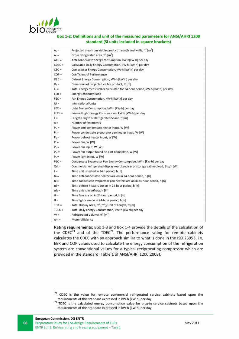
68
European Commission, DG ENTR
Preparatory Study for Eco-design Requirements of EuPs
ENTR Lot 1: Refrigerating and freezing equipment – Task 1
May 2011
Box 1-2: Definitions and unit of the measured parameters for ANSI/AHRI 1200
standard (SI units included in square brackets)
Ae = Projected area from visible product through end walls, ft2 [m
2]
Ar = Gross refrigerated area, ft2 [m
2]
AEC = Anti-condensate energy consumption, kW·h[kW·h] per day
CDEC = Calculated Daily Energy Consumption, kW·h [kW·h] per day
CEC = Compressor Energy Consumption, kW·h [kW·h] per day
COP = Coefficient of Performance
DEC = Defrost Energy Consumption, kW·h [kW·h] per day
Dh = Dimension of projected visible product, ft [m]
Et = Total energy measured or calculated for 24-hour period, kW·h [kW·h] per day
EER = Energy Efficiency Ratio
FEC = Fan Energy Consumption, kW·h [kW·h] per day
IU = International Units
LEC = Light Energy Consumption, kW·h [kW·h] per day
LECR = Revised Light Energy Consumption, kW·h [kW·h] per day
L = Length Length of Refrigerated Space, ft [m]
n = Number of fan motors
Pai = Power anti-condensate heater input, W [W]
Pc = Power condensate evaporator pan heater input, W [W]
Pd = Power defrost heater input, W [W]
Pf = Power fan, W [W]
Pfi = Power fan input, W [W]
Pfo = Power fan output found on part nameplate, W [W]
Pli = Power light input, W [W]
PEC = Condensate Evaporator Pan Energy Consumption, kW·h [kW·h] per day
Qrt = Commercial refrigerated display merchandiser or storage cabinet load, Btu/h [W]
t = Time unit is tested in 24 h period, h [h]
ta = Time anti-condensate heaters are on in 24-hour period, h [h]
tc = Time condensate evaporator pan heaters are on in 24-hour period, h [h]
td = Time defrost heaters are on in 24-hour period, h [h]
tdt = Time unit is in defrost, h [h]
tf = Time fans are on in 24-hour period, h [h]
tl = Time lights are on in 24-hour period, h [h]
TDA = Total Display Area, ft² [m²]/Unit of Length, ft [m]
TDEC = Total Daily Energy Consumption, kW•h [kW•h] per day
Vr = Refrigerated Volume, ft3
[m3]
ηm = Motor efficiency
Rating requirements: Box 1-3 and Box 1-4 provide the details of the calculation of
the CDEC73 and of the TDEC74. The performance rating for remote cabinets
calculates the CDEC with an approach similar to what is done in the ISO 23953, i.e.
EER and COP values used to calculate the energy consumption of the refrigeration
system are conventional values for a typical reciprocating compressor which are
provided in the standard (Table 1 of ANSI/AHRI 1200:2008).
73
CDEC is the value for remote commercial refrigerated service cabinets based upon the
requirements of this standard expressed in kW·h [kW·h] per day. 74
TDEC Is the calculated energy consumption value for plug-in service cabinets based upon the
requirements of this standard expressed in kW·h [kW·h] per day.
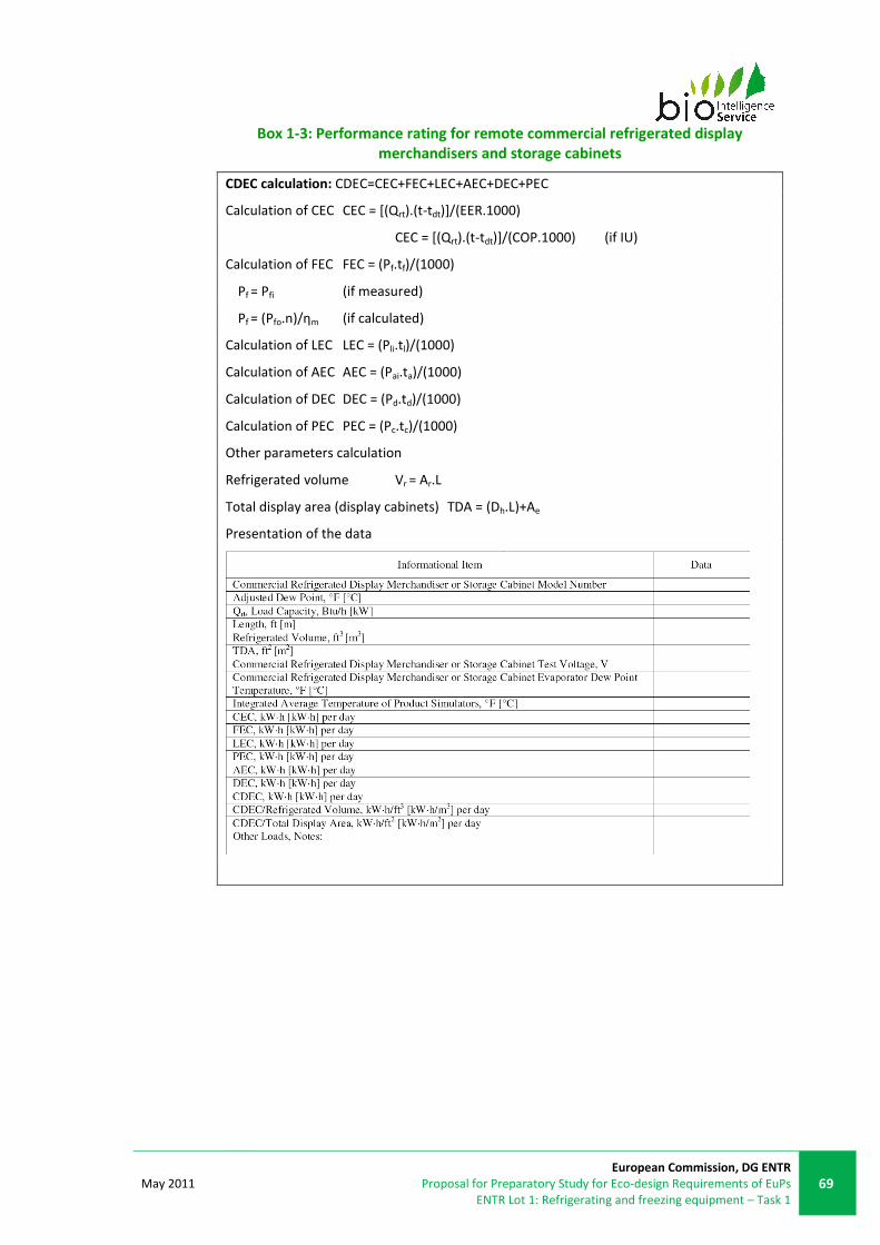
May 2011
European Commission, DG ENTR
Proposal for Preparatory Study for Eco-design Requirements of EuPs
ENTR Lot 1: Refrigerating and freezing equipment – Task 1
69
Box 1-3: Performance rating for remote commercial refrigerated display
merchandisers and storage cabinets
CDEC calculation: CDEC=CEC+FEC+LEC+AEC+DEC+PEC
Calculation of CEC CEC = [(Qrt).(t-tdt)]/(EER.1000)
CEC = [(Qrt).(t-tdt)]/(COP.1000) (if IU)
Calculation of FEC FEC = (Pf.tf)/(1000)
Pf = Pfi (if measured)
Pf = (Pfo.n)/ηm (if calculated)
Calculation of LEC LEC = (Pli.tl)/(1000)
Calculation of AEC AEC = (Pai.ta)/(1000)
Calculation of DEC DEC = (Pd.td)/(1000)
Calculation of PEC PEC = (Pc.tc)/(1000)
Other parameters calculation
Refrigerated volume Vr = Ar.L
Total display area (display cabinets) TDA = (Dh.L)+Ae
Presentation of the data

70
European Commission, DG ENTR
Preparatory Study for Eco-design Requirements of EuPs
ENTR Lot 1: Refrigerating and freezing equipment – Task 1
May 2011
Box 1-4: Performance rating for self-contained commercial refrigerated display
merchandisers and storage cabinets
TDEC calculation: TDEC = Et/L
Other parameters:
Refrigerated volume Vr = Ar.L
Total display area TDA = (Dh.L)+Ae
Presentation of the data
1.3.1.5 US ASHRAE Standard 72-2005
Relevance: Service cabinets
ASHRAE Standard 72-2005 Method of Testing Commercial Refrigerators and
Freezers (ANSI Approved) is the revision of Standard 72-1998. It combines
standard 72-1998 for open refrigerators and standard 117-2002 for closed
refrigerators. It prescribes a uniform method of testing both remote and self-
contained open and closed commercial refrigerators and freezers for rating so that
comparative evaluations can be made of energy consumption, product
temperature performance, refrigeration load, the suction pressures required and
other performance factors. The standard also clarifies door opening requirements,
shelf loading and test definitions, and includes requirements that improve the
consistency of ambient temperatures.
1.3.1.6 CAN/CSA-C827-98 (R2008)
Relevance: Service cabinet
CAN/CSA-C827-98 (revised in 2008) Energy Performance Standard for Food Service
Refrigerators and Freezers applies to commercial refrigerators, refrigerator-
freezer cabinets that are intended for storing and holding food products and other
perishable merchandise. It applies to manufacturers’ standard catalogue-type
equipment, closed cabinets of the unitary, self-contained type; and commercial
refrigerated storage cabinets, regardless of their shape, size or configuration. It
does not apply to remote-condensing commercial refrigerators and freezers, walk-
in refrigerators and freezers, water coolers, refrigerated vending machines, ice-
making machines, soft serve, slush and shake-dispensing freezers and extruders.

May 2011
European Commission, DG ENTR
Proposal for Preparatory Study for Eco-design Requirements of EuPs
ENTR Lot 1: Refrigerating and freezing equipment – Task 1
71
The CSA standard contains minimum performance criteria for annual energy
consumption that vary with the volume of the refrigerator or freezer (see
§1.4.2.1).
1.3.1.7 Comparison of volume measurement methods
Stakeholders commented on their volume measurement methods. There are four
volume measurement methods that have been considered as the most important:
• Method 1: This method considers the internal vertical distance from the
lowest usable shelf to the highest load-line multiplied by the usable shelf
area when the door is closed.
• Method 2: This methodology considers the space within the equipment
with all movable parts removed. It provides a gross volume, from which
the space required for the evaporator and air ducts free flow should be
deducted.
• Method 3 (corresponding to EN 441): This method measures the
equipment with all movable parts installed. The load limits are identified,
considering areas where the air channels that should not be blocked at
any moment. Volume inferior to 100x100x100mm (cubic testing package)
should not be included for the calculation. The measurement should fit
primitive geometrical shapes. The volume of the bottom shelf shall not be
included in the total volume.
• Method 4 (corresponding to EN 23953 revision proposal75
): Where n is
the number of shelves, net volume is calculated via: Shelf or drawer base
area x (loading height – n x thickness of shelf).
Following are some of the issues associated with trying to develop a harmonised
and accurate measurement method which reflects the amount of food that the
product can store during use76:
• In some cabinets, the shelves are recessed and therefore would not
actually have food on them.
• Many cabinets are quite poor in terms of load lines and dimensions and so
any rule can be interpreted in a variety of ways (hence it would be useful
to insist that load lines are marked).
• The number of test packs might be a good method, though loading is only
approximately half the shelf height.
Another stakeholder comment noted that the volume of the test packs used in
determining the energy consumption should also be used in the energy/volume
index calculation (there is an inherent inaccuracy when testing energy with one
volume of product and then introducing another volume of product when
calculating the energy efficiency index)77.
Care should be taken when selecting a method considering the trade-off between
convenience and accuracy.
75
Source: CECED Italia 76
Source: London South Bank University 77
Source: Adande Refrigeration

72
European Commission, DG ENTR
Preparatory Study for Eco-design Requirements of EuPs
ENTR Lot 1: Refrigerating and freezing equipment – Task 1
May 2011
1.3.1.8 Testing and protocols
There are three main elements of testing for service cabinets, due to their
significant impact on energy consumption: ambient temperature and humidity, M-
package positioning, and door openings. Climate classes are used to define
standard temperatures and humidity, and positioning of M-packages is defined
within the standards. The term “protocol” is used to describe the assumed use
pattern that is replicated by a specific door opening pattern during the controlled
test.
The standards EN ISO 23953, the development of this standard by CECED and the
standard EN 441 all have slight protocol variations. These reflect differences in
assumed use patterns, in order that the testing method accurately reflects real
consumption.
� EN 441-5:1996
Cabinets with doors are tested over a 48-hour period where the cabinet door(s)
are opened cyclically for 12 h within each 24-hour period. If the cabinet is fitted
with lights these are switched on 1 h before the start of the door-opening test and
switched off 1 h after the door-opening period.
Start 0 - 12 hours 12 – 24
hours
24
hours
24 – 36 hours 36 – 48
hours
3 min
open
each door opened
6 times per hour
for 12 seconds(1)
each door
closed
3 min
open
each door opened
6 times per hour
for 12 seconds1
each
door
closed
1Door open at an angle of greater than 60° for 10 s. If the cabinet has multiple doors, the doors are
opened in sequence within each 10-min period.
� EN ISO 23953:2005
The test for closed refrigerated cabinets should always be carried out on a
complete cabinet, regardless of the number of doors or lids. The requirements
state that the cabinet lighting should be switched on for a period of 12 h; followed
by 12 h with the cabinet lighting switched off. With the night covers removed,
leave the cabinet lighting switched on for a period of 12 h; followed by 12 h with
the night covers on and the cabinet lighting switched off.
Start 0 - 12 hours 12 – 24 hours
3 min open (2) each door or lid opened 6 times
per hour for 6 seconds(3)
each door closed
(2)Where a cabinet is provided with more than one door or lid, each door or lid
shall be opened for 3 min consecutively.
(3)Door open at an angle of greater than 60° for 4 s. If the cabinet has multiple
doors, the doors are opened in sequence within each 10-min period — where
there are two doors, for example, open door no. 1 at 0 min, door no. 2 at 5 min,
door no. 1 at 10 min, door no. 2 at 15 min, and so on.

May 2011
European Commission, DG ENTR
Proposal for Preparatory Study for Eco-design Requirements of EuPs
ENTR Lot 1: Refrigerating and freezing equipment – Task 1
73
� CECED Italia EN ISO 23953:2005 revision
Procedure: during the 24 hours, consumption measurements should be recorded
as follows.
• Freezing
Start 0 - 4 hours 4 – 8
hours
8 hours 8 – 12 hours 12 – 24
hours
1 min
open
each door opened
6 times per hour
for 6 seconds(4)
each
door
closed
1 min
open
each door opened
6 times per hour
for 6 seconds(4)
each
door
closed
• Refrigeration
Start 0 – 12 hours 12 – 24 hours
2 min open cycle each door opened 6 times per hour
for 6 seconds(4)
each door closed
(4)Where more than one door or lid pertains to the cabinet to be tested, the
sequence in which the doors and lids are opened shall be staggered.
� FR NF AC D40-003:2006 (§1.3.6.5)
1st period 2nd period 3rd period
5 hours 3 hours 1 hour
Door closed:
cooling of M-
packages to
required
temperatures
Door openings
For high temperature: The door is open to 90°, every 5
min for 10 seconds. In the case of the product having
several doors or drawers, they should be opened one
at a time, every 5 minutes in turn.
For low temperature: The door is open to 90° every 15
min for 30 seconds. In the case where the device has
several doors or drawers, they should be open one at
a time, every 15 min in turn.
Door closed:
cooling of M-
packages to
required
temperatures
Understanding of product use patterns is important when developing testing
standards. A field study tested products using different door opening patterns,
demonstrating the impact this can have on energy consumption.

74
European Commission, DG ENTR
Preparatory Study for Eco-design Requirements of EuPs
ENTR Lot 1: Refrigerating and freezing equipment – Task 1
May 2011
Electricity consumption vs. dooropenings
y = 0,079x + 8,0439
R2 = 0,8951
y = 0,0347x + 3,9587
R2 = 0,1248
0
2
4
6
8
10
12
0 5 10 15 20 25
No. of dooropenings [1/24h]
Ele
ctric
ity c
onsu
mpt
ion
[kW
h/24
h]
Old 660
New 660
Figure 1-21: Electricity consumption vs. door openings for the freezers78
Electricity consumption vs. Door openings
y = 0,0134x + 4,7319
R2 = 0,3784
y = 0,0049x + 1,0926
R2 = 0,7229
0
2
4
6
8
10
12
0 50 100 150 200 250 300
No. of door openings [1/24h]
Ele
ctric
ity c
onsu
mpt
ion
[kW
h/24
h]
Old 660
New 660
Figure 1-22: Electricity consumption vs. door openings for the refrigerators78
78
Pedersen, P-H., Soe, L. and Jensen, F. New Generation of Professional Kitchen Appliances with
Natural Refrigerants and Reduced Energy Consumption, Danish Technological Institute and Gram
Commercial. Presented at 6th Gustav Lorentzen Natural Working Fluids Conference, Glasgow, UK
(2004)

May 2011
European Commission, DG ENTR
Proposal for Preparatory Study for Eco-design Requirements of EuPs
ENTR Lot 1: Refrigerating and freezing equipment – Task 1
75
1.3.2. BLAST CABINETS
1.3.2.1 EN 328:1999
Relevance: Blast cabinets, heat exchangers
Heat exchangers. Test procedures for establishing the performance of forced
convection unit air coolers for refrigeration. This standard is applied to evaporators
in direct dry expansion of refrigerant, liquid feed by means of a pump and
machines working with liquids, and includes non-ducted unit air coolers for
refrigeration operating.
It is used to evaluate blast cabinet component performance, but not the overall
performance of the equipment. It establishes performance evaluation methods.
These methods determine the net power of the evaporator, air-flow, and energy
consumption.
This standard does not include safety aspects or evaluation of conformity.
1.3.2.2 EN 327:2000
Relevance: Blast cabinets, packaged refrigeration systems
Heat exchangers – Forced convection air cooled refrigerant condensers – Test
procedure for establishing performance. This standard applies to remote
condensers, air-forced convection condensers where refrigerant change phase is
produced.
This is standard is used to determine the functioning of blast cabinet components,
but not of blast cabinets by themselves. This standard establishes performance
evaluation.
However, it does not provide compliance values, and does not apply to condensers
meant to be installed inside machines or cabinets, or condensing units with sub-
cooling units.
1.3.2.3 DE DIN 8953/8954
Relevance: Blast cabinets
There is evidence that DIN 8953/8954 Household frozen storage cabinets has been
used by the industry to evaluate the performance of blast cabinets. However, it
has been phased out.79
1.3.3. WALK-IN COLD ROOMS
1.3.3.1 Introduction
This section on test standards for walk-in cold rooms covers methodologies to
assess the parameters and performance of both the components that impact on
the energy performance of walk-in cold rooms, and the energy performance of the
products themselves.
Firstly, methods for testing of the insulation panels and insulated box are
described. Subsequently, options for testing of the refrigeration system are
79
Source: www.gemm-srl.com/ita/images/abbattitorirunner.pdf

76
European Commission, DG ENTR
Preparatory Study for Eco-design Requirements of EuPs
ENTR Lot 1: Refrigerating and freezing equipment – Task 1
May 2011
discussed. Testing methods for the various individual components are then
covered, and lastly methods for testing the energy consumption of the entire
product are considered.
For the evaluation of refrigeration systems, standards described within other
sections may also be relevant. These include EN 327 for packaged systems
(§1.3.2.2), and EN 13771 (§1.3.5.1) and EN 13215 (§1.3.5.2) for remote condensing
systems.
1.3.3.2 European Technical Approval Guideline (ETAG) 021 and 01680
Relevance: framework for design of cold storage kits
The ETAG 021 Cold storage premises kits is divided into two parts: Part 1 “Cold
storage room kits” and Part 2 “Cold storage building envelope and building kits”
covering specific aspects related to different intended uses. Part 2, covering
products that might be constructed outdoors, has additional elements mainly
relating to the need to weather-proof the structure.
This guideline was established in the context of Directive 89/106/EEC on
construction products (§1.4.8.6). European technical approvals are used to assess
the suitability of a product for its intended use in cases where there is no
harmonised standard, no recognised national standard and no mandate for a
European standard and where the Commission feels, after consulting the Member
States within the Standing Committee on Construction, that a standard cannot or
cannot yet be prepared. The European Organisation of Technical Approvals
(EOTA), which groups together the national approvals bodies, can draw up
technical approvals guidelines in respect of a construction product or family of
construction products, acting on a mandate from the Commission and after
consulting the Standing Committee on Construction81.
The scope of the guideline covers cold storage kits whose components are pre-
designed and prefabricated by one (or various) manufacturer(s) to be produced in
series and three-dimensional prefabricated transportable rooms. In the context of
the guideline, thermally insulating products are those with a declared thermal
conductivity of less than 0.06W/m.K at +10°C. Components put on the market
separately are not covered by ETAG 021, although much of the data on technical
characteristics is provided on a component basis.
Cold storage building kits contain at least the load bearing structure and wall and
roof panels, or wall panels and roof (with ceiling panels). Some important points to
note:
• The technical equipment (e.g. cooling systems and other electrical
equipment) is excluded from the guidelines in both cases.
• The enclosure82 is made out of sandwich panels with insulating cores.
• The kits follow pre-designed technical solutions for joints and assembly.
• For all premises, floors may be included depending on its characteristics.
80
European Technical Approval Guideline 021. Cold storage premises kits. Draft Edition 2004. 81
ec.europa.eu/enterprise/sectors/construction/documents/legislation/cpd/index_en.htm 82
The term “envelope” in this guideline refers to the waterproof layer and not to a structural part of
the building.

May 2011
European Commission, DG ENTR
Proposal for Preparatory Study for Eco-design Requirements of EuPs
ENTR Lot 1: Refrigerating and freezing equipment – Task 1
77
• The guidelines cover cold stores intended to store products at
temperatures below +15°C and above -40°C.
• As the rooms are designed for specific internal temperature intervals,
these must be specified by the ETA applicant and declared in the ETA
(although specific component characteristics such as thermal performance
are not linked to temperatures).
During the approval issuing process, the approval bodies will assess whether the
kit design, the components and the installation and maintenance foreseen by the
European Technical Approval (ETA) applicant lead to an overall favourable
assessment of the kit for that (or those) intended use (or uses). Kits that conform
to the ETA can be CE marked, all others cannot, and if a kit manufacturer wants to
use a previously CE-marked kit for another intended use, they must therefore have
the ETA revised or apply for a new ETA.
Components put on the market separately are not covered by ETAG 021.
Contractors that assemble components of cold store kits and place them on the
market are not obliged to apply for an ETA, however applying for one will provide
the advantage that their component has been proved fit for intended use
(whereas fitness for purpose of combinations of components placed on the market
separately will need to be tested onsite).
The ETA alone is not sufficient to enable placing of the product on the market. In
addition to the technical specification, an attestation of conformity, resulting in an
EC Declaration of conformity, is required before CE marking is possible.
Figure 1-23 presents a number of possibilities that exist for placing cold storage
premises kits on the market:
Figure 1-23: Placing cold storage kits on the market
Case A is the "normal" case. The ETA-holder is also the party that also performs
the attestation of conformity tasks and signs the EC Declaration of conformity. The
kits go directly from the ETA-holder to the market.
In Case B, the products are stored by a distributor who places the kits on the
market. Because the latter does not modify (in any way) the kit, the kit
manufacturer (ETA-holder) can also perform all A/C tasks. In this case, it is possible

78
European Commission, DG ENTR
Preparatory Study for Eco-design Requirements of EuPs
ENTR Lot 1: Refrigerating and freezing equipment – Task 1
May 2011
that the distributor benefits from a "duplicate" ETA and that the kits bear the
distributor's name.
Case C represents the possibility that the kit manufacturer has an ETA that covers
a number of possible kits, where an intermediate manufacturer places on the
market some or all of them. The choice of the components and therefore also the
performance of the kit is determined by the intermediate manufacturer and he
becomes responsible for signing the EC Declaration of conformity and CE Marking
of the kit.
Case D is the case where the kit manufacturer does not obtain his ETA and does
not put the kit on the market. His responsibility is reduced to that of a supplier.
The intermediate manufacturer obtains the ETA and also performs the attestation
of conformity tasks. There must be a technical and legal link between the
manufacturer(s) or supplier(s) and the party signing the EC Declaration of
conformity.
ETAG 021 specifies standardised methods to evaluate the characteristics of the
product and its fitness, judging methods and assumptions, and makes other
recommendations (see Table 1-21). As ETAG 021 covers required evaluation to
comply with the Directive on construction products (89/106/EEC), the EC
Foodstuff Directive (91/43/ECC), and the EC food contact material Directives (the
Framework Directive 89/109/It), many requirements link to associated
characteristics of structural integrity and health and safety compliance, and also
characteristics pertaining to energy economy and heat retention are covered.
Some of them apply to both cold room kits and cold room building kits, while
others are relevant only to one type of them:
Table 1-21: Aspects considered in ETAG 021 scope to evaluate Cold rooms kits
and Cold rooms building kits83
Aspect CRK* CRBK**
Mechanical resistance x x
Safety in case of fire
Reaction to fire x x
Resistance to fire x x
External fire performance
x
Hygiene, health and environment
Dangerous substances release x x
Vapour permeability x x
Moisture resistance x x
Fitness for contact with food and feedstuff x x
Water tightness x
Air tightness x x
Safety in use
83
Source: European Technical Approval Guideline 021. “Cold storage premises kits”. Draft Edition
2004.

May 2011
European Commission, DG ENTR
Proposal for Preparatory Study for Eco-design Requirements of EuPs
ENTR Lot 1: Refrigerating and freezing equipment – Task 1
79
Aspect CRK* CRBK**
Impact resistance x x
Mechanical resistance
Fixing resistance x x
Mechanical resistance of wall, ceiling and floor panels x x
Mechanical resistance of the cold storage building enclosures x x
Eccentric loads resistance x x
Slipperiness x x
Safety against personal injuries by contact x x
Safety against entrapment x x
Safety against collapse (due to air pressure differences) x x
Resistance to horizontal and provisions preventing falling due to changes in
level or sudden drops x
Protection against noise
Airborne sound insulation x
Impact sound insulation x
Sound absorption x
Energy economy and heat retention
Thermal performance x
Thermal resistance x
Air permeability x x
Water vapour permeability x x
Thermal inertia x
Durability, serviceability and identification
Durability x x
Serviceability x x
Identification x x
* Cold rooms kits ** Cold rooms building kits
Within the documentation, it states methods and calculation to assess the kit and
components.
For thermal performance, the guideline proposes means to evaluate the product
at component level. For example, the hot box method is proposed as a means of
evaluating doors, gates and windows.
Assessment of the panels which are main components of cold storage rooms, i.e.
composite panels with insulating cores, is primarily based on the draft harmonised
technical specifications EN 14509 "Double metal faced insulated sandwich panels"
(§1.3.3.3) or ETA-Guideline 016 "Self supporting light weight composite panels".
Both of these refer to other standards for the thermal conductivity and aged
thermal conductivity, including laboratory test methods such as EN 12939, EN
12667, EN 12664 (§1.3.3.5) for measurement of thermal conductivity, and
statistical calculation methods in EN 13162 to EN 13167 (EN 13164 and EN 13165

80
European Commission, DG ENTR
Preparatory Study for Eco-design Requirements of EuPs
ENTR Lot 1: Refrigerating and freezing equipment – Task 1
May 2011
are discussed in §1.3.3.4) and EN ISO 10456 for aged thermal conductivity.
Thermal resistance and the corresponding thermal transmittance (U-value) of the
panels shall be calculated according to EN ISO 6946 (a calculation method)
(§1.3.3.7) or a hot box procedure under ETAG016, and under EN 14509 thermal
transmittance is calculated under a formula.
For doors, gates and windows, ETAG021 states that the thermal resistance of
panels can be used. Alternatively, the hot-box test method (EN ISO 12567-1:2010
as described in §1.3.3.6) can be offered. Other component methods are
calculations, and use standard data from tables.
For air permeability, test standards are proposed for the kit, doors and gate and
composite panels. These are:
• ISO 12569:2000 Thermal performance of buildings -- Determination of air
change in buildings -- Tracer gas dilution method
• EN 13829:2001 Thermal performance of buildings. Determination of air
permeability of buildings. Fan pressurization method
• EN 12114:2000 Thermal performance of buildings. Air permeability of
building components and building elements. Laboratory test methods (as
set out in EN 14509:2006 and ETA-Guideline 016)
• BS EN 1026:2000 Windows and doors. Air permeability. Test method (with
EN 12207:2000 Windows and doors. Air permeability. Classification)
1.3.3.3 EN 14509:2006
Relevance: to assess insulation properties of sandwich panels
This standard includes the specifications, evaluation and monitoring of factory-
made, self-supporting, double skin metal faced insulating panels. Due to the great
variety of sandwich panel applications, profiles, adhesives, insulation core
materials and production lines, different levels of mechanical performance can be
achieved.
The main parameters of interest measured in respect to energy performance of
the cold rooms is the thermal conductivity, λ, and thermal transmission, U-value,
as described.
The standard references EN 13162 to EN 13167, for specifications of testing aged
thermal conductivity of different insulation materials and it proposes a calculation
method for the thermal transmittance of the panel.
Since October 2010, CE marking has been compulsory for all sandwich panels sold
in the EU84.
1.3.3.4 EN 13164:2009-02 and EN 13165:2009-02
Relevance: to assess insulation properties of panel core material
Thermal insulation products for buildings. EN 13164:2009-02 Factory made
products of extruded polystyrene foam (XPS) and EN 13165:2009-02 Factory made
rigid polyurethane foam (PUR) products. With the introduction of harmonized
European standards for evaluating the characteristics of insulation foam, a new
84
Source: www.rockwool-sandwichpanel.com/solutions/en+14509

May 2011
European Commission, DG ENTR
Proposal for Preparatory Study for Eco-design Requirements of EuPs
ENTR Lot 1: Refrigerating and freezing equipment – Task 1
81
method of measurement and declaration of aged thermal conductivity (λ) and
thermal resistance was implemented to create a level playing field for insulation
materials where permanent blowing agents are used. Hence, manufacturers of
insulating panels must now declare the aged λ value. The aged λ is test is
described in Annex C, and is performed at +10°C.
1.3.3.5 EN 12664:2001, EN 12667:2001 and EN 12939:2001
Relevance: to assess thermal performance of insulating panels
Thermal performance of building materials and products. Determination of
thermal resistance by means of guarded hot plate and heat flow meter methods.
Dry and moist products of medium and low thermal resistance - EN 12664:2001
medium and low thermal resistance, EN 12667:2001 high and medium thermal
resistance, EN 12939:2001 thick products of high and medium thermal resistance.
The guarded hot plate consists of a two specimen around a heated plate, which is
sandwiched between two cooling plates. With the Heat Flow Meter, samples are
tested between two heat flux sensors in fixed or adjustable temperature
gradients. After a few minutes for the system to reach equilibrium, the built-in PC
or external computer determines the thermal conductivity and thermal resistance
of the sample, hence the steady-state heat flow through the specimen is
measured.
1.3.3.6 ISO 12567-1:2010
Relevance: to assess thermal performance of insulating panels, doors and
windows
Thermal performance of windows and doors -- Determination of thermal
transmittance by the hot-box method -- Part 1: Complete windows and doors
ISO 12567-1:2010 specifies a method to measure the thermal transmittance of a
door or window system. It is applicable to all effects of frames, sashes, shutters,
blinds, screens, panels, door leaves and fittings.
For the “hot box” method, the insulation product is installed in a dividing wall
between two rooms with different temperatures. A “hot box” consisting in a five-
sided box is installed in the warm room, with the open side facing the insulation
product to be tested. The temperature inside and outside the box has to be the
same, so the transmittance is made through the insulation product into the cold
room. Simultaneous measurement of the temperature difference across the item
tested enables to calculate the thermal resistance.
The U-value can also be tested directly by measuring the different air
temperatures in both rooms, using calibrated testing equipment.

82
European Commission, DG ENTR
Preparatory Study for Eco-design Requirements of EuPs
ENTR Lot 1: Refrigerating and freezing equipment – Task 1
May 2011
Figure 24: Diagram of thermal resistance test method85
1.3.3.7 EN ISO 6946:2007
Relevance: to assess thermal performance of insulation panels
Building components and building elements -- Thermal resistance and thermal
transmittance -- Calculation method
This standard provides the method of calculation of the thermal resistance and
thermal transmittance of building components and building elements, excluding
doors, windows and other glazed units, curtain walling, components which involve
heat transfer to the ground, and components through which air is designed to
permeate.
The calculation method is based on the appropriate design thermal conductivities
or design thermal resistances of the materials and products for the application
concerned.
The method applies to components and elements consisting of thermally
homogeneous layers (which can include air layers).
ISO 6946:2007 also provides an approximate method that can be used for
elements containing inhomogeneous layers, including the effect of metal
fasteners, by means of a correction term given in Annex D. Other cases where
insulation is bridged by metal are outside the scope of ISO 6946:2007.
1.3.3.8 EN 12114:2000
Relevance: to assess air permeability of insulation panels
Thermal performance of buildings. Air permeability of building components and
building elements. Laboratory test methods
85
Source: SP Technical Research Institute of Sweden, available online at:
www.sp.se/sv/units/energy/Documents/ETi/SP%20INFO%202000_17%20E%20eng%20-
%20Thermal%20transmittance%20by%20hot%20box%20method.pdf

May 2011
European Commission, DG ENTR
Proposal for Preparatory Study for Eco-design Requirements of EuPs
ENTR Lot 1: Refrigerating and freezing equipment – Task 1
83
Under EN 14509, the following specifications are made for this standard, when
testing panels.
The dimensions of the test assembly shall be as large as necessary to be
representative of the intended use. The assembly shall not be less than 1,200mm x
2,400mm. The joints of the modules comprising the test assembly shall be
representative, i.e. the same length per m² as in end use. Both horizontal and
vertical joints shall be incorporated where these are an intrinsic part of the panel
assembly.
The air permeability shall be measured with a pressure difference of 50 Pa
between the inside and outside of the test assembly. The air permeability (air loss)
shall be determined in terms of m³/m².h at 50 Pa.
1.3.3.9 BS EN 4376-1:1991
Relevance: to assess performance of insulating box
BS EN 4376-1 Electrically operated blood storage refrigerators defines standards
for closed reach-in type refrigerators designed and equipped for the storage of
whole blood and red cell components that need to be kept within specified limits
of temperature. The refrigerators are intended for use in hospitals and blood
collecting centres. Facilities for the storage of frozen blood products are excluded.
The standard specifies that the insulation shall have a thermal transfer coefficient
not greater than 0.35 W/(m2·K) and should be vapour sealed. The preferred type
of insulation is “foamed in place”, and the standard requires that if “slab type”
insulation (blocks of pre-foamed insulation) is used, it should be bonded at joints
and to both external and internal linings with a thermal break (for fire protection)
between the inner and outer surfaces. Doors should be self-closing type with inner
doors or flaps to reduce entry of ambient air to the compartment.
A method of testing for temperature within the net storage volume of the cabinet
on failure of the air recirculating fan to verify that either:
a) the air temperature within the storage volume remains within the limits of 0 °C
to 8 °C; or
b) an audible and visual alarm operates.
The temperature should be measured at the bottom and top of the storage
volume using a calibrated recording device during the duration of the test. The
operator should set the mean air temperature within the storage volume to
maintain the temperature between +1°C and +7°C, and once reached, stop the air
recirculating fan, continuing until whichever occurs first:
a) until an audible and visual alarm is operated; or
b) 24h passes.
This test is known in the trade as the “holdover” test.
1.3.3.10 Agreement on the international carriage of perishable foodstuffs (ATP)
Relevance: test method to assess insulation performance of the insulated box and
refrigeration system, either as a whole system or individually
ATP is the multi-lateral agreement between Signatory Countries (Contracting
Parties) for overland cross border carriage of perishable foodstuffs. It ensures that

84
European Commission, DG ENTR
Preparatory Study for Eco-design Requirements of EuPs
ENTR Lot 1: Refrigerating and freezing equipment – Task 1
May 2011
vehicles used for this carriage meet agreed international standards. The standards
apply to the bodywork (insulating box) and refrigeration units.
The agreement also details the following aspects of interest:
• Classifications of equipment, based on operation storage temperature
ranges (with a mean outside temperature of + 30 °C and maintaining
continuously temperature Ti inside the empty insulated box):
o Class A: Ti may be chosen between + 12 °C and 0 °C inclusive;
o Class B: Ti may be chosen between + 12 °C and - 10 °C inclusive;
o Class C: Ti may be chosen between + 12 °C and - 20 °C inclusive.
o Class D: Ti is equal to or less than 0 °C;
o Class E: Ti is equal to or less than - 10 °C;
o Class F: Ti is equal to or less than - 20 °C.
In the case of classes A, B and C, any desired practically constant Ti (in
conformity with the standards defined above), while in the case of classes
D, E and F a fixed practically constant Ti (in conformity with the standards
defined above).
• Procedures for testing the insulated enclosure and refrigeration
equipment, either combined (within an insulated testing laboratory) or
separately (insulated box tested within insulated laboratory, refrigeration
unit measured under other accepted standard conditions). Hence
refrigerating capacity of the refrigeration system can be calculated by
attachment to a calorimeter box, and the cooling capacity matched to the
heat load requirement of the insulated box (as measured under the test
conditions). Specifications of the test include:
o K coefficient measured either by the internal cooling method or by
the internal heating method;
o conditions in the testing laboratory (such as air flow;
o temperature measuring points;
o period of test; and
o parameter variances permitted.
For test procedure details, please see Annex 1-1, §1.14.4.
1.3.3.11 PAS 57:2003
Relevance: to assess performance of refrigeration system
PAS 57:2003 Cellar cooling equipment — Procedure for determining performance
and calculating energy efficiency defines procedures and conditions for measuring
the performance of cellar cooling equipment and calculating the energy efficiency,
expressed as a COP, providing a means for comparing product energy efficiency.
Cellar cooling equipment is a refrigeration system designed to maintain an indoor
environment at a condition suitable for the storage of chilled beverages, typically
+10°C to +12°C.
The standard specifies procedures for determining the performance and energy
efficiency of cellar cooling equipment with a capacity between 2 kW and 12 kW, at
a standard rating condition of +10°C air onto the evaporator and +32°C air onto
the condenser, using air-cooled condensers categorized as either:

May 2011
European Commission, DG ENTR
Proposal for Preparatory Study for Eco-design Requirements of EuPs
ENTR Lot 1: Refrigerating and freezing equipment – Task 1
85
a) a packaged system, comprising all components mounted on one base for
“through the wall” installation; or
b) a split system, with the equipment supplied in two parts (evaporator and
condensing unit) to be connected on site; or
c) a remote system, with equipment supplied in three parts (evaporator,
compressor/receiver unit and condenser) to be connected on site.
All components supplied as part of the equipment shall be included in the
evaluation. The standard specifies the conditions to be maintained in two rooms,
Test room A which will contain the condensing unit, consisting of the compressor,
condenser, liquid receiver (where fitted), filter drier, or compressor/receiver set
plus air cooled condenser or outdoor part of the packaged system, and Test room
B (calorimeter room) which will contain the evaporator and expansion valve
(where fitted to the evaporator). In addition, piping lengths and dimensions are
specified for the split and remote system types.
The system cooling capacity and energy consumption are measured to provide the
COP, and the requirements for an evaluation report are set out.
The temperature and humidity is controlled in test room A, which shall have
sufficient volume for unrestricted airflow through the condenser. The test room B
shall be an insulated chamber with a heat load to simulate cellar conditions, and
shall have a thermal mass such that during the system efficiency test, the room
temperature increases at a rate less than 1°C in 5 min when the cellar cooling
equipment is turned off. The size of the room B is also specified so that no
obstacles are positioned at a specific distance to the evaporators and the volume
of the room is according to the air flow generated by the evaporator.
The cooling capacity shall be measured under the following conditions:
• The relative humidity of the test room B shall be of (80±5)%
• Single phase equipment shall be tested at (230±5) V and (50±0.5) Hz
• Three phase equipment shall be tested at (400±8) V and (50±0.5) Hz
• Air onto the condenser at (32±0.5)°C
• Test room B temperature at (10±0.5)°C, with the average temperature
during the 1 h period being between 9.8°C and 10.2°C.
• Cellar unit operating continuously
• The cooling capacity shall be measured at steady state conditions
(specified above), achieved at least 30 min prior to evaluation and
maintained for 1 h.
The energy consumption shall be measured under the following conditions:
• Cooling capacity measured as explained above
• Air onto the condenser at (20±0.5)°C
• Test room B temperature at (10±0.5)°C
• Cellar unit cycling on its thermostat

86
European Commission, DG ENTR
Preparatory Study for Eco-design Requirements of EuPs
ENTR Lot 1: Refrigerating and freezing equipment – Task 1
May 2011
• The energy consumption shall be measured at steady state conditions
(specified above), achieved at least 30 min prior to evaluation and
maintained for 2 h.
The coefficient of performance (COP) shall be calculated by dividing the system
cooling capacity (in kW) by the system energy consumption (in kW). In order to
calculate the system energy consumption in kW, the energy consumption
measured in kWh is divided by the duration of the test in hours.
1.3.3.12 AHRI 1251 (SI) (and AHRI 1250 (I-P))
Relevance: to assess energy consumption of whole product
AHRI 1251 (SI units) Performance rating of Walk-In Coolers and Freezers applies to
walk-in coolers and freezers with refrigeration system configurations:
• integrated, comprising a single package;
• matched system, with evaporator unit (“unit cooler”) integral, and
condensing unit is separated and located either indoor or outdoor;
• unit cooler integral, connected to a central, shared condensing unit.
The control system may be integral, but if this is not the case the performance of
the control system should be tested as well (normally by a separate party). The
standard defines a method that evaluates the refrigeration system and the walk-in
“box” heat load separately.
This standard does not apply to:
• rooms for telecommunication switch gear or other equipments that need
to be cooled;
• enclosures for medical, scientific or research purposes;
• performance testing of large parallel rack refrigeration systems
(condensing units).
Conditions for evaluation under specified test procedures to provide Standard
Ratings for the refrigeration system are defined for different product
configurations (indoor/outdoor condensing unit; fixed capacity matched, two
capacity matched and variable capacity matched refrigeration systems), and there
is a requirement to calculate the Application Rating, consisting of a Capacity Rating
plus the associated power input and COP. Measured test results for cooling
capacity and COP shall be no less than 95% of the published rating.
The standard then sets out equations to calculate the box heat load for various
product configurations (indoor/outdoor condensing unit; fixed capacity matched,
two capacity matched and variable capacity matched refrigeration systems).
The walk-in box load is comprised of a high load period (BLH) of the day
corresponding to frequent door openings, product loading events, and other design
load factors, and a low load period of the day (BLL) corresponding to the minimum
load resulting from conduction, internal heat gains from equipment that is not
related to the refrigeration system, and infiltration when the door is closed. Both
the BLH and BLL are defined as a linear relationship with outdoor ambient
temperature. This relationship accounts for the influence of outdoor ambient on
the conduction and infiltration loads for a “typical” walk-in box.86

May 2011
European Commission, DG ENTR
Proposal for Preparatory Study for Eco-design Requirements of EuPs
ENTR Lot 1: Refrigerating and freezing equipment – Task 1
87
BLH and BLL are functions of the cooling capacity of the refrigeration system at
specific temperatures, as set out in section 6 of the standard. For example BLH
being 0.7 times, and BLL 0.1 times, the cooling capacity for a cooler at +32°C
ambient, and BLH being 0.8 times, and BLL 0.4 times cooling capacity for a freezer
at +32°C ambient.
The standard then sets equations that allow the calculation of the Annual Walk-in
Energy Factor (AWEF), a factor indicating efficiency.
“Annual Walk-in Energy Factor (AWEF). A ratio of the total heat, not including the
heat generated by the operation of refrigeration systems, removed, in watt-hours,
from a walk-in box during one year period of usage for refrigeration to the total
energy input of refrigeration systems, in watt-hours, during the same period.”86
1.3.3.13 US test procedures for walk-in coolers and freezers
Relevance: minimum insulation standards for product components
Test methods prescribed to confirm achievement of minimum standards (see
§1.4.3.1):
• The R-value shall be the 1/K factor multiplied by the thickness of the
panel.
• The K factor shall be based on ASTM test procedure C518-2004.
• For calculating the R-value for freezers, the K factor of the foam at 20°F (-
6.7°C) (average foam temperature) shall be used.
• For calculating the R-value for coolers, the K factor of the foam at 55°F
(+12.8 °C) (average foam temperature) shall be used.
1.3.3.14 US DOE proposed test procedures for walk-in coolers and freezers
Relevance: component approach to testing and standards
The US Energy Independence and Security Act of 2007 enacted on December 19,
2007, establishes energy conservation standards for certain consumer products
and commercial and industrial equipment, including walk-in cold rooms and walk-
in freezers. The DOE’s Building Technologies Program has been developing
proposals for testing energy consumption of walk-in cooler and freezer rooms. A
Notice of Proposed Rulemaking was published in January 2010, and a public
meeting held in March 2010 to discuss the options.
The US DOE published on April 15th 2011 a final rule establishing test procedures
for measuring the energy efficiency of certain walk-in cold room components,
including panels, doors and refrigeration systems, which will be used for the
process of evaluation of potential minimum performance standards in a
concurrent study. Representations on product performance to this concurrent
study must therefore use the test methods outlined in the final rule. In addition, a
certification, compliance and enforcement (CEE) final rule was published March 7,
2011.
The US DOE notes that the component approach addresses the unique challenges
posed by regulation of walk-in cold rooms, including the facts that the products
86
AHRI. 2009 Standard for Performance Rating of Walk-In Coolers and Freezers.2009

88
European Commission, DG ENTR
Preparatory Study for Eco-design Requirements of EuPs
ENTR Lot 1: Refrigerating and freezing equipment – Task 1
May 2011
are frequently assembled using components produced by several manufacturers,
and that installers of walk-in cold rooms may not be equipped to test all of the
components that comprise a walk-in cold room.
Summary of DOE approach
Walk-in cold rooms are categorised as walk-in “coolers” or walk-in “freezers”.
The final rule references US and EU test standards, including:
• AHRI 1250 (I–P)–2009, ‘‘2009 Standard for Performance Rating of Walk-In
Coolers and Freezers”
• ASTM C1363–05, ‘‘Standard Test Method for Thermal Performance of
Building Materials and Envelope Assemblies by Means of a Hot Box
Apparatus”
• DIN EN 13164:2009–02, ‘‘Thermal insulation products for buildings—
Factory made products of extruded polystyrene foam (XPS)—
Specification”
• DIN EN 13165:2009–02, ‘‘Thermal insulation products for buildings—
Factory made rigid polyurethane foam (PUR) products—Specification”
• NFRC 100–2010[E0A1], ‘‘Procedure for Determining Fenestration Product
U-factors”
In addition, the final rule refers to the test standard ASTM C518-04 “Standard Test
Method for Steady-State Thermal Transmission Properties by Means of the Heat
Flow Meter Apparatus”, which is used to measure characteristics required to meet
minimum standards specified in EPCA, and the result of this test is also required to
provide an input to the calculations in the final rule.
Overview of test procedures and energy consumption and efficiency calculations
The energy consumption of components is calculated, including for refrigeration
system, panels, doors and electronic equipment.
AHRI 1250 is used to calculate the refrigeration system daily energy consumption
and an overall efficiency factor, the annual walk-in efficiency factor (AWEF), test
condition adapted for the relevant operation temperature (cooler or freezer). This
standard includes methods for testing of the refrigeration system to evaluate
cooling capacity and energy consumption, hence refrigeration system COP.
Daily energy consumption of the walk-in cold room surfaces (panels and doors) are
calculated separately. Firstly U-factors for panels and doors are evaluated through
test procedures, test condition adapted for the relevant operation temperature
(cooler or freezer). The U-factor takes into account composite panel or door
characteristics, such as insulation type, structural members, and transparent
material (e.g. glass) and panel thickness. The U-factor is then multiplied with
nominal refrigeration system performance characteristics for the relevant
operation temperature (cooler or freezer), to calculate energy consumption (total
energy consumption is calculated as an effect of the door’s thermal load on a
“nominal” refrigeration system and hence the energy consumed by the
refrigeration system to meet this load).
The nominal efficiency is described using an energy efficiency ratio (EER), with
values proposed for coolers and freezers being 12.4 Btu/W-h (COP of 3.63) and 6.3
May 2011
European Commission, DG ENTR
Proposal for Preparatory Study for Eco-design Requirements of EuPs
ENTR Lot 1: Refrigerating and freezing equipment – Task 1
89
Btu/W-h (COP of 1.85)87 respectively (these values correspond to the nominal EER
values for the refrigeration test procedure for unit coolers connected to central
condensing units under AHRI 1250–2009 in respect to assumed adjusted dewpoint
temperature of -7°C and -32°C respectively for coolers and freezers), and the US
DOE highlights that these are only for comparative purposes and are not intended
to represent the efficiency of the refrigeration system that would be paired with
the components.
Finally, daily energy consumption of any integrated electronic devices, and the
effect of their heat load on the nominal refrigeration system, are added.
Test procedure for doors
Doors can be display (integrating a transparent section) or non-display type, and
are tested in through the same procedure. NFRC 100-2010[E0A1] is used to
evaluate the U-factor (thermal transmittance measured in Btu/h-ft2-°F) through
the door. NFRC 100-2010[E0A1] also allows verified computer models to simulate
performance to reduce testing burden.
This energy consumption of the nominal refrigeration system due to thermal
transmittance is then combined with the energy consumption of any electrical
components integrated into the door, in kWh/day. Assumptions on the nominal
refrigeration system are the same for all doors tested, depending if the door is to
be used for walk-in coolers or walk-in freezers, to enable direct comparison within
the temperature categories.
Direct electricity consumption of the door will be the sum of the rated power of
the component multiplied by the assumed operation time. To facilitate the
calculation of electricity consumption, fixed assumptions for the percentage time
off (PTO) of common electrical devices used in doors are specified in sections 4.4.2
and 4.5.2 of Appendix A of the final rule for display and non-display door types
respectively. For any electrical device not covered in the assumptions provided in
the final rule, then a PTO of 25% can be used where a manufacturer demonstrates
that the device is controlled by a preinstalled control system, timer, or other auto-
shut-down system. The test procedure also provides the method of calculating the
added energy consumption due to the heat load placed on the refrigeration
system by any electrical device(s) installed in the door.
A formula is provided in the final rule to produce a energy consumption of the
door. The calculations are described in the final rule, sections 4.4 and 4.5 of
Appendix A.
Test procedures for panels
In the final rule, a panel is described as the fully manufactured product containing,
but not limited to the insulation, skin, framing material, other structural members,
or any combination of these, as opposed to just the “insulation”, which is
synonymous with “foam”. A display panel is a panel that is partially or entirely
comprised of glass, a transparent material, or both, and is used for display
purposes. A non-display panel can be either a floor or non-floor panel, and since
these are typically formed in the same way from a composite of insulation,
framing and facer material, they will be measured in the same way. The US DOE is
adopting a separate approach depending on whether a panel is a display or non-
87
1 Btu = 0.293 W.h, hence COP = EER / 3.412

90
European Commission, DG ENTR
Preparatory Study for Eco-design Requirements of EuPs
ENTR Lot 1: Refrigerating and freezing equipment – Task 1
May 2011
display type, hence display panels are tested under a different regime, specified in
section 4.1 in Appendix A of the final rule (similar to that of the test procedure for
doors as described above).
For non-display (floor, wall and ceiling) panels, US DOE specifies that ASTM C518-
04 must still be used to determine the K-factor of the insulation (R-value is equal
to 1/K-factor multiplied by thickness of the panel) as required by EPCA. The US
DOE emphasises that the current final rule does not prevent adherence to the
existing EPCA regulation on R-value of the insulation, which will remain a
requirement, and highlights that this R-value is not related to the structural
members that may be included in the panel. The use of ASTM C1363-05 allows
more accurate testing of the energy performance of the panels, and captures the
effects of the structural members.
To account for insulation aging and, by extension, to the increased energy
consumption due to reduced performance of the insulation over lifetime, the US
DOE has adopted the test methods set out in Annex C of EN 13164:2009–02 or EN
13165:2009–02, to measure long term thermal resistance (LTTR), thereby
eliminating time as a variable that could affect the measured performance of the
insulation. One change to the EN standards used to determine the LTTR is the
mean temperatures for testing conditions – these are changed to follow the ASTM
C518-04 mean temperatures of 55°F (+12.8 °C) and 20°F (-6.7°C) respectively for a
cooler and a freezer under either EN 13164:2009–02 or EN 13165:2009–02, in
place of the +10°C specified in the standards. The LTTR R-value is divided by the
initial R-value (measured under ASTM C518-04), to provide a degradation factor.
The degradation factor (unitless) is then applied to the U-factor of the panel (this
calculation is provided in sections 4.2 and 4.3 of Appendix A), increasing the
thermal transmission of the panel to account for future insulation aging effects,
the U-factor having been measured under ASTM C1363-05 (as described below).
Appendix A also sets out the requirements of the sample used to assess LTTR.
The final rule specifies that manufacturers use the ASTM C1363-05 procedure to
test a pair of 4 ft by 8 ft (1.22m by 2.43m)88 test panels, with tolerance of +/- 1 ft
(0.3m), joined with the same fastening system and materials that would be used
during use, to obtain a core U-factor and an edge U-factor. The weighted
percentage of edge U-factor and core U-factor is used to calculate total U-factor
when applying the results of the test panels to other floor and non-floor panels of
the same thickness, construction and materials (i.e. to use a “basic model”
approach that reduces testing burden). The final rule provides an example of such
a calculation in section III.B.2.a.
The US DOE notes that the aging test is only applied to foams incorporating low
conductivity blowing agents, but as expanded polystyrene is not affected by the
issue it does not need to be tested for aging. In addition, polyisocyanurate (PIR)
insulation is covered under the test for polyurethane (PUR) insulation in EN
13165:2009–02.
A formula is provided in the final rule to produce a energy consumption of the
door. The calculations are described in the final rule, sections 4.2 and 4.3 of
Appendix A.
Test procedure for refrigeration system
88
1 ft = 0.304 m
May 2011
European Commission, DG ENTR
Proposal for Preparatory Study for Eco-design Requirements of EuPs
ENTR Lot 1: Refrigerating and freezing equipment – Task 1
91
The US DOE considered the refrigeration system as an individual component of the
walk-in cold room. It therefore establishes a test procedure to assess performance
of the refrigeration system itself, assuming nominal envelope characteristics.
There is discussion on the options for classification of refrigeration system types,
which are categorised as dedicated single-package systems containing condensing
and evaporating units, split systems containing an evaporator unit (or “unit
cooler”) and dedicated condensing unit, and unit coolers that receive refrigerant
from a central condensing system that is shared with other equipment. For the last
type, those connected to shared, central refrigeration systems, the compressor
and condenser are considered out of scope.
AHRI 1250–2009 is the basis for testing of the refrigeration systems, covering all
three system types, and this includes a method for measuring the refrigeration
capacity and electrical energy consumption for the condensing unit and the unit
cooler, as well as off-cycle fan energy and the defrost subsystem under specified
conditions, the conditions being different for indoor and outdoor locations for the
condensing unit, and also for cooler or freezers.
The AHRI standard also specifies a calculation methodology to compute the AWEF
for the refrigeration system under a specified load profile, and the procedure
allows for testing of components individually and calculating the AWEF from the
component test results. This flexibility enables manufacturers to test unit coolers
and condensing units separately, and used them together in new refrigeration
systems (test results are independent of the matched unit cooler or condensing
unit attached to the respective condensing unit or unit cooler for the purposes of
the test).
In contrast, test results of individual components produced by different
manufacturers are in the form of a performance curve to facilitate calculation of
matched performance, which creates some limitation as meaningful comparison
between unit coolers is therefore not possible without matching of the tested unit
coolers to the same condensing unit. However, if unit coolers are tested and rated
as if matched to a central condensing unit, they can be compared, hence it is
relatively simple for manufacturers of cooling units to provide both matched
performance data, to allow assessment of design performance, and performance
relative to the use of a nominal central condensing unit, for cross-market
comparative purposes.
For the calculation of energy use of central refrigeration systems, a nominal
efficiency that accounts for the type of system’s ability to reject heat is used (i.e.
depending on indoor or outdoor).
Formulae for calculation of the annual energy consumption are provided in the
revisions to §431.304, part (8)(i) to (iii), in Appendix A of the final rule.
The US DOE has also left open the option of manufacturers (particularly those
manufacturers producing low-volume customised equipment) using their own
methods to calculate refrigeration system energy consumption, whether
calculation or computer simulation, after substantiation of the method with test
data and acceptance of the method from the US DOE, in order to reduce testing
burden. These can be in the form of alternate rating methods (ARMs) or alternate
efficiency determination methods (AEDMs).
Temperature conditions

92
European Commission, DG ENTR
Preparatory Study for Eco-design Requirements of EuPs
ENTR Lot 1: Refrigerating and freezing equipment – Task 1
May 2011
For the calculation of thermal transmittance across the insulation panels (sections
4.1 to 4.5 in Appendix A to the final rule), the following temperatures are used:
• Internal cooled space for cooler: 35°F (+1.7°C)
• Internal cooled space for freezer: -10°F (-23.3°C)
• External space for cooler and freezer: 75°F (+23.9°C)
• Subfloor temperature for cooler and freezer: 55°F (+12.8 °C)
Following this, the final rule specifies that for the ASTM C1363-05 procedure, the
“hot side” for non-floor panel is 75°F (+23.9°C) and for floor panel is 55°F (+12.8
°C), and on the “cold side”, 35°F (+1.7°C) for the cooler and -10°F (-23.3°C) for the
freezer. This is also the case for NFRC 100-2010[E0A1].
The final rule specifies a change to the EN 13164:2009–02 and EN 13165:2009–02
standards used to determine the LTTR in section 5.3 in Appendix A. The mean
temperatures for testing conditions are changed to 55°F (+12.8 °C) and 20°F (-
6.7°C) respectively for a cooler and a freezer (to follow the ASTM C518-04).
Temperatures used in AHRI 1250–2009 for nominal evaporation temperature are
unchanged, at -7°C and -32°C respectively for coolers and freezers, and condensing
air temperatures are assumed to be +32°C indoors, and up to +35°C outdoors.
Responsibility for testing and information requirements
These are described in full in the CEE final rule. In summary, the responsibility for
compliance extends to both component manufacturer and assembler. Component
manufacturers are responsible for certifying compliance of the components to be
used for walk-in cold rooms, while assemblers of the complete walk-in cold room
are required to use only certified components (the component manufacturer is
not responsible for the end-users implementation of the component – only of the
components compliance as designed).
Regarding the basic model approach, the US DOE has decided that this approach
should be used for each key component within the walk-in cold rooms, rather than
the product overall, and as long as the basic model covers equipment with
characteristics that are essentially the same with respect to energy consumption
or energy efficiency the CCE final rule allows for use of basic models at the
discretion of the manufacturer (in other words a component may be grouped with
others as long as its tested performance is at least as good as the certified rating).
However, the concept is applied slightly differently to panels, doors and
refrigeration systems, due to their different characteristics.
• Panels: smaller panels may have higher proportion of framing material to
non-framing material, or the use of different framing material, which may
increase heat transmission and affect the overall U-factor, hence would
need separate testing and certification – however, increases in width and
height would not be expected to detrimentally affect the U-value if all
other characteristics were equal.
• Doors: as with panels, those with essentially identical energy consumption
levels can be grouped into a basic model and rated conservatively.
• Refrigeration system: models may be grouped, if they have essentially
identical electrical, physical and functional characteristics that affect

May 2011
European Commission, DG ENTR
Proposal for Preparatory Study for Eco-design Requirements of EuPs
ENTR Lot 1: Refrigerating and freezing equipment – Task 1
93
energy consumption or efficiency, hence the tested performance must be
at least as good as the certified rating.
Information requirements
The requirements for information provision are set out in § 429.12 and § 429.53.
The certification report needs to include the following: door type, the R-value of
the wall, ceiling and door insulation (except for glazed portions of the doors or
structural members), the R-value of the floor insulation (for freezers only), the
evaporator fan motor type, the efficacy of the lighting including ballast losses, and
a declaration that the manufacturer has incorporated the applicable design
requirements. In addition, for those walk-in coolers and freezers with transparent
reach-in doors and windows: the glass type of the doors and windows (e.g.,
double-pane with heat reflective treatment, triple-pane glass with gas fill), and the
power draw of the antisweat heater in watts.
Any calculations to support the certified ratings must be retained along with the
test data of the test panels for maintaining records of all models covered under
that “basic model”.
Areas not taken forward
The US DOE has in addition described in its final rule the areas of investigation that
have not been taken forward into the requirements for testing and subsequent
minimum standards.
Infiltration is no longer considered, due to the shift to a component approach, and
the US DOE considers that this issue is most likely negligible compared to other
energy consumption pathways. In addition, the US DOE states that this issue relies
heavily on on-site construction practice rather than component performance, and
notes that door opening infiltration reduction devices are already mandated
through EPCA. However, the issue of infiltration may be re-examined by the US
DOE in future rulemaking.
The US DOE sets outs reasons for exclusion of testing of moisture absorption or
vapour permeance in foam at the time of the final rule, but states that one of its
laboratories is currently testing methods to evaluate moisture absorption on R-
value.
Since the approach is component-based, electrical components not part of one of
the components (door, display panel or refrigeration system) are not covered, but
the US DOE highlights that EPCA requirements on lighting efficacy standards must
still be maintained.
Regarding the effect of structural members on LTTR, the US DOE states that due to
no known tests for edge sealing of panels, this issue is not considered, although it
is highlighted as a potential factor to consider in future rulemaking.
Open areas included in walk-in cold rooms are excluded from the US DOE final
rule.
Appendix A of the final rule
As described at several points, the final rule contains an Appendix A which lists
aspects such as amendments to existing test standard operating conditions,
procedures, calculations, and other calculations.

94
European Commission, DG ENTR
Preparatory Study for Eco-design Requirements of EuPs
ENTR Lot 1: Refrigerating and freezing equipment – Task 1
May 2011
1.3.4. PROCESS CHILLERS
1.3.4.1 EN 14511:2007
Relevance: Industrial process chillers
The EN 14511 Air conditioners, liquid chilling packages and heat pumps with
electrically driven compressors for space heating and cooling - Terms and
definitions, test conditions, test methods and requirements, specifies the terms,
definitions, test conditions, methods and requirements for the rating and
performance of air- and water-cooled air conditioners, liquid chilling packages, air-
to-air, water-to-air, air-to-water and water-to-water heat pumps with electrically
driven compressors when used for space heating and/or cooling. Liquid chilling
packages are typically tested with this standard, being not restricted to comfort
equipment. It was stated by stakeholders that the conditions specified within this
standard for testing are extreme, and sometimes not a realistic representation of
actual working conditions.
The scope of this standard covers:
• Factory-made units that can be ducted.
• Factory-made liquid chilling packages with integral condensers or for use
with remote condensers.
• Factory-made units of either fixed capacity or variable capacity by any
means.
• Packaged units, single split and multisplit systems are covered by this
standard. Single duct and double duct units are covered by the standard.
• In the case of units consisting of several parts, this standard applies only to
those designed and supplied as a complete package, except for liquid
chilling packages with remote condenser.
• This standard is primarily intended for water and brine chilling packages
but can be used for other liquid subject to agreement.
• Air-to-air air conditioners which evaporate the condensate on the
condenser side.
• The units having their condenser cooled by air and by the evaporation of
external additional water are not covered by this standard.
• This standard does not apply to units using transcritical cycles, e.g. with
CO2 as refrigerant.
• Installations used for heating and/or cooling of industrial processes are not
within the scope of this standard.
The standard EN 14511 part 2 provides the ambient conditions for performance
testing and rating for the following configurations:
• Outdoor units
• Indoor units
• Air-to-air units in heating mode
• Air-to-air units in cooling mode

May 2011
European Commission, DG ENTR
Proposal for Preparatory Study for Eco-design Requirements of EuPs
ENTR Lot 1: Refrigerating and freezing equipment – Task 1
95
• Water-to-air units in heating mode
• Water-to-air units in cooling mode
• Water-to-water units in heating mode
• Water-to-water units in cooling mode
• Air-to-water in heating mode
• Air-to-water in cooling mode
• Liquid chilling packages with remote condenser
• Liquid chilling packages for heat recovery condenser
• Basic, multiple circuit and modular air-cooled multisplit systems in the
heating mode
• Basic, multiple circuit and modular air-cooled multisplit systems in the
cooling mode
• Modular heat recovery air-cooled multisplit systems
• Basic, multiple circuit and modular water-cooled multisplit systems in the
heating mode
• Basic, multiple circuit and modular water-cooled multisplit systems in the
cooling mode
The tolerances permitted in the declared values are the following:
Table 1-22: Tolerances permitted in EN 14511
Parameter Tolerance
Tested cooling and heating capacity 0.88*declared capacity
Tested EER (cooling mode) 0.85*declared EER
Tested COP (heating mode) 0.85*declared COP
EN 14511 part 3 provides the test procedures (measurements, apparatus, data
required, calculations) and EN 14511 part 4 specifies the minimum requirements
for chilling packages to ensure a proper functioning of the machines. The
performance data required should be tested as per EN 14511 parts 2 and 3.
1.3.4.2 EN 15218:2006
Relevance: Air conditioning and liquid chillers
EN 15218:2006 “Air conditioners and liquid chilling packages with evaporatively
cooled condenser and with electrically driven compressors for space cooling.
Terms, definitions, test conditions, test methods and requirements”. is also of
relevance.
1.3.4.3 prEN 14825
The prEN 14825:2009 Air conditioners, liquid chilling packages and heat pumps,
with electrically compressors, for space heating and cooling- Testing and rating at
part load conditions and calculation of seasonal performance provides testing
methods for refrigeration and air-conditioning equipment considering part-load
conditions and seasonal performance.

96
European Commission, DG ENTR
Preparatory Study for Eco-design Requirements of EuPs
ENTR Lot 1: Refrigerating and freezing equipment – Task 1
May 2011
The scope of this standard covers “air conditioners, heat pumps and liquid chilling
packages in part load conditions”. The standard applies to factory made units as
defined in EN14511-1, except single duct, control cabinet and close control units.
The standard provides the calculation methods for the determination of reference
seasonal energy efficiency (SEER and SEERon) and reference seasonal coefficient of
performance (SCOP , SCOPon and SCOPnet).
The standard provides testing conditions and calculation methods for efficiency at
part load for:
• Air-to-air units in the cooling mode
• Water-to-air units and brine-to-air units in the cooling mode
• Air-to-water units in the cooling mode
• Water-to-water units and brine-to-water units in the cooling mode
• Air-to-air units in the heating mode
• Water-to-air units and brine-to-air units in the heating mode
• Air-to-water units in the heating mode (low/medium/high temperature
application)
• Water-to-water units and brine-to-water units in the heating mode
(low/medium/high temperature application)
This standard is only available in draft version (draft by the CEN TC 113 WG 7) and
it is still not approved at the time of writing this report.
1.3.4.4 AHRI 550/590-2003
Relevance: Industrial process chillers (vapour compression)
The AHRI 550/590-2003 Standard for performance rating of water-chilling
packages using the vapor compression cycle establishes definitions, test
requirements, rating requirements and minimum data requirements for published
ratings, marking and nameplate data; and conformance conditions.
Scope: “This standard applies to factory-made vapour compression refrigeration
water-chilling packages, including one or more hermetic or open drive
compressors”89. These equipments include:
• water-, air- or evaporatively-cooled condensers
• air-, water-cooled heat reclaim condensers
• packages supplied without a condenser
Test requirements: The tests required for this standard shall be conducted in
accordance with Appendix C of the AHRI 550/590-2003 standard.
Rating conditions: Table 1-23 specifies standard rating conditions for all water-
chilling packages.
89
AHRI Standard 550/590-2003. Standard for performance rating of water-chilling packages using
the vapor compression cycle. 2003

May 2011
European Commission, DG ENTR
Proposal for Preparatory Study for Eco-design Requirements of EuPs
ENTR Lot 1: Refrigerating and freezing equipment – Task 1
97
Table 1-24 presents part-load rating conditions defined by ANSI/AHRI 550/590-
2003 to permit the development of part-load performance over a range of
operating conditions.
Rating requirements:
The minimum rating requirements include the following:
• Net refrigerating capacity, refrigeration tons (RT) [kW]
• Total power input to chiller, bhp or kW, as applicable
• Energy efficiency, expressed as EER, COP or kW/ton
• Evaporator Fouling Factor
• Chilled water entering and leaving temperatures, °F [°C], or leaving
water temperature and temperature difference, °F [°C]
• Evaporator water pressure drop (inlet to outlet), psi or ft H2O [kPa]
• Chilled water flow rate, gpm [L/s]
• Nominal voltage, V, and frequency, Hz, for which ratings are valid

98
European Commission, DG ENTR
Preparatory Study for Eco-design Requirements of EuPs
ENTR Lot 1: Refrigerating and freezing equipment – Task 1
May 2011
Table 1-23: Standard rating conditions of water chilling packages
Water-cooled Evaporatively-cooled Air-cooled
Condenser water
Entering +85°F +29.4°C
Flow rate 3.0
gpm/tonne
0.054 L/s
per kW
Condenser fouling factor allowance
Water-side 0.00025
h*ft2*°F/Btu
0.000044
m2*°C/W
Air-side 0.0 ft2*°F/Btu
0.0
m2*°C/W
0.0
h*ft2*°F/Btu
0.0
m2*°C/W
Entering air
Dry-bulb +95.0°F +35.0°C
Wet-bulb +75°F +23.9°C
Evaporator water
Leaving +44.0°F +6.7°C +44.0°F +6.7°C +44.0°F +6.7°C
Flow rate 2.4
gpm/tonne
0.043 L/s
per kW 2.4 gpm/tonne
0.043 L/s
per kW
2.4
gpm/tonne
0.043 L/s
per kW
Evaporator fouling factor allowance
Water-side 0.0001
h*ft2*°F/Btu
0.000018
m2*°C/W
0.0001
h*ft2*°F/Btu
0.000018
m2*°C/W
0.0001
h*ft2*°F/Btu
0.000018
m2*°C/W
Evaporator fouling factor allowance
Saturated
discharge +105.0°F +40.6°C +105.0°F +40.6°C +125.0°F +51.7°C
Liquid
refrigerant +98.0°F +36.7°C +98.0°F +36.7°C +105.0°F +40.6°C
Barometic
pressure 29.92 in Hg 101.3 kPa 29.92 in Hg 101.3 kPa 29.92 in Hg 101.3 kPa

May 2011
European Commission, DG ENTR
Proposal for Preparatory Study for Eco-design Requirements of EuPs
ENTR Lot 1: Refrigerating and freezing equipment – Task 1
99
Table 1-24: Part-load conditions for rating
1.3.4.5 ANSI/AHRI 560-2000
Relevance: Industrial process chillers (absorption)
The ANSI/AHRI 560-2000 Absorption water chilling and water heating packages
establishes: definitions; test requirements; rating requirements; minimum data
requirements for published ratings; marking and nameplate data; and conformity
conditions.
Scope: This standard applies to water-cooled single effect steam and hot water
operated water chilling units, water-cooled double-effect steam and hot water
operated water chilling units, and double-effect direct-fired (natural gas, oil, LP
gas) water chilling/heating units. Water is the refrigerant and LiBr (lithium
bromide) the absorbent. This standard does not apply to air-cooled applications,
heat pump applications, exhaust gas fired applications and non-standard units.
Test requirements: The tests required for this standard shall be conducted in
accordance with Appendix C of ANSI/AHRI 560-2000 standard.
Rating conditions: Table 1-25 specifies standard rating conditions of absorption
water chilling and water heating packages.
Table 1-26 presents part-load rating conditions defined by ANSI/AHRI 560-2000 to
permit the development of part-load performance over a range of operating
conditions.
Rating requirements:

100
European Commission, DG ENTR
Preparatory Study for Eco-design Requirements of EuPs
ENTR Lot 1: Refrigerating and freezing equipment – Task 1
May 2011
The minimum rating requirements include the following:
• Net refrigerating capacity, tons [kW]
• Total Energy Input to the chiller in MBH90 [kW], as applicable
• Direct Fired, MBH [kW] based on Higher Heating Value
• Indirect Fired, MBH [kW]
• Chiller Efficiency, expressed as COP or MBH/ton
• Evaporator Fouling Factor, as stated in Table 1 of the standard
• Chilled water entering and leaving temperatures, °F [°C] (as stated in
Table 1 of the standard), or leaving water temperature and temperature
difference, °F [°C]
• Evaporator water pressure drop (inlet to outlet), psi or ft H2O [kPa]
• Chilled water flow rate, gpm [L/s]
• Average electrical power consumption, kW [kW] for all auxiliary
components including solution and refrigerant pumps, purge, control
panel, burner fan, burner controls, etc. Power required by system water
pumps shall be excluded.
• Absorber/condenser water pressure drop (inlet to outlet), psi or ft H2O
[kPa]
• Any two of the following:
o Entering absorber/condenser water temperature, °F [°C]
o Leaving absorber/condenser water temperature, °F [°C]
o Water temperature rise through the absorber/condenser, °F [°C]
• Absorber/condenser water flow rate, gpm [L/s].
• Fouling Factors, as stated in Table 1-25.
90
MBH is the expression of BTU's (British Thermal Units) in thousands.

May 2011
European Commission, DG ENTR
Proposal for Preparatory Study for Eco-design Requirements of EuPs
ENTR Lot 1: Refrigerating and freezing equipment – Task 1
101
Table 1-25: Standard rating conditions of absorption water chilling packages

102
European Commission, DG ENTR
Preparatory Study for Eco-design Requirements of EuPs
ENTR Lot 1: Refrigerating and freezing equipment – Task 1
May 2011
Table 1-26: Part-load Rating conditions of absorption water chilling packages
1.3.4.6 CAN/CSA-C743-09
Relevance: Industrial process chillers
The CAN/CSA-C743-09 Performance Standard for Rating Packaged Water Chillers
applies to factory-designed and prefabricated water-cooled chiller/heater units,
single-effect indirect-fired by steam or hot water, and double-effect, both indirect-
fired by steam or hot water and direct-fired by oil, natural gas or LP gas; water is
the refrigerant and lithium bromide is the absorbent. This standard does not apply
to absorption chiller/heater units with air-cooled condensers, nor to applications
employing heat pumping or exhaust gas firing.

May 2011
European Commission, DG ENTR
Proposal for Preparatory Study for Eco-design Requirements of EuPs
ENTR Lot 1: Refrigerating and freezing equipment – Task 1
103
1.3.4.7 AS/NZS 4776: 200891
Relevance: Industrial water chillers
The AS/NZS 4776:2008 Liquid-chilling packages using the vapour compression
cycle standard aims to establish a method to rate the performance of factory-
made liquid chilling packages using the vapour compression cycle. The scope of
the standard includes: air- and water-cooled liquid-chilling packages of cooling
capacity 350kW and above.
The AS/NZS 4776.1 does not cover:
• liquid-chilling packages driven by other than electrical motors;
• air-cooled liquid-chilling packages with centrifugal fans;
• liquid-chilling packages with remote condensers; and
• liquid-chilling packages for fluids other than water.
This standard is linked to a MEPS (see §1.3.4.7)
1.3.5. REMOTE CONDENSING UNITS
1.3.5.1 EN 13771:2003/ EN 13771:2007
Relevance: Remote condensing unit, compressor and condenser
EN 13771-1:2003 Compressor and condensing units for refrigeration –
performance testing and test methods for refrigerant compressors applies to
refrigerant compressors and describes a number of selected performance test
methods. These methods provide sufficiently accurate results for the
determination of the refrigerating capacity, power absorbed, refrigerant mass
flow, isentropic efficiency and the coefficient of performance. This European
Standard applies only to performance tests conducted at the manufacturer's
works.
EN13771-2: 2007 Compressor and condensing units for refrigeration. Performance
testing and test methods. Part 2: Condensing units. This part of EN 13771 applies
only to condensing units for refrigeration and describes a number of selected
performance test methods. These methods provide sufficiently accurate results for
the determination of the refrigerating capacity, power absorbed, refrigerant mass
flow and the coefficient of performance.
1.3.5.2 EN 13215:2000
Relevance: Remote condensing unit
EN 13215:2000 (ISO 917:1989) Condensing units for refrigeration. Rating
conditions, tolerance and presentation of manufacturer’s performance. This
standard is applicable to equipments with positive-displacement compressors and
it aims to specify rating conditions, tolerances and presentation of manufacturer’s
performance data, usable for comparison of different units. The performance of
91
Source: Standard Australia/Standard New Zealand. 4776.1:2008. “Liquid-chilling packages using
the vapour compression cycle”. 2008

104
European Commission, DG ENTR
Preparatory Study for Eco-design Requirements of EuPs
ENTR Lot 1: Refrigerating and freezing equipment – Task 1
May 2011
the units (related to the refrigeration capacity) includes correction factors and
based on full load operation92.
Table 1-27 Standard reference points specified in EN 13215:2000
The tolerances permitted in the data presented by the manufacturers shall not be
higher than:
• -10.0% in the refrigerating capacity for medium evaporating temperature
• +10.0% in the power absorbed for medium evaporating temperature
• -12.5% in the refrigerating capacity for low evaporating temperature
• -12.5% in the power absorbed for low evaporating temperature
In no case, the tolerance on COP be higher than 10%.
1.3.5.3 ASHRAE Standard 23-2005
Relevance: Packaging condensing unit, compressor and condenser
The ASHRAE 23-2005 Methods of Testing for Rating Positive Displacement
Refrigerant Compressors and Condensing Units (ANSI approved) applies to the
methods of testing for rating single-stage positive-displacement refrigerant
compressors and condensing units that do not have liquid injection and are
operated at subcritical (saturated) temperatures of the refrigerant. It also applies
to the methods of testing for rating single-stage positive-displacement refrigerant
compressors and condensing units that incorporate liquid injection that is
controlled by a steady flow rate method and are operated at subcritical
(saturated) temperatures of the refrigerant.
1.3.5.4 ISO/R 916:1968
Covers the determination of the technical performance of a refrigerating system,
but not the functional duty of a complete installation or the performance of its
individual components. The term "refrigerating system" implies the conventional
vapour compression type consisting of compressing, condensing and evaporating
apparatus, together with the interconnecting piping and the accessories necessary
to complete the refrigerant circuit.
92
Source: http://necis.ihs.com/document/abstract/OWZNHBAAAAAAAAAA
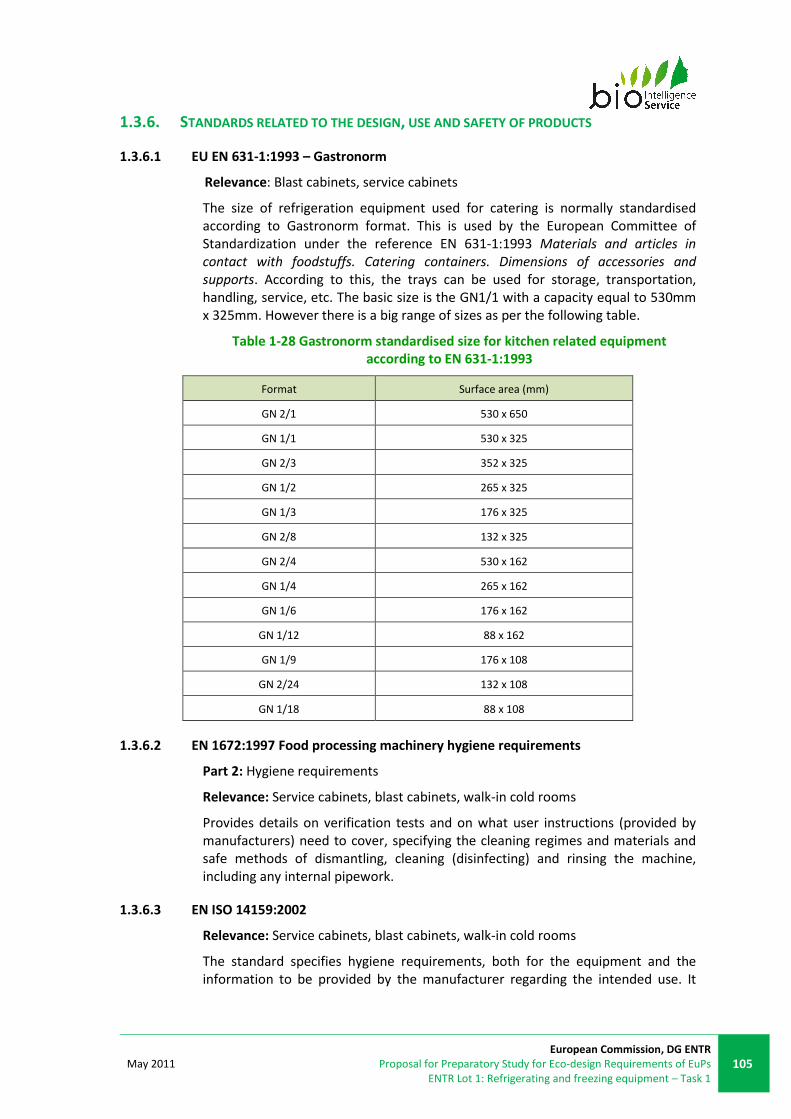
May 2011
European Commission, DG ENTR
Proposal for Preparatory Study for Eco-design Requirements of EuPs
ENTR Lot 1: Refrigerating and freezing equipment – Task 1
105
1.3.6. STANDARDS RELATED TO THE DESIGN, USE AND SAFETY OF PRODUCTS
1.3.6.1 EU EN 631-1:1993 – Gastronorm
Relevance: Blast cabinets, service cabinets
The size of refrigeration equipment used for catering is normally standardised
according to Gastronorm format. This is used by the European Committee of
Standardization under the reference EN 631-1:1993 Materials and articles in
contact with foodstuffs. Catering containers. Dimensions of accessories and
supports. According to this, the trays can be used for storage, transportation,
handling, service, etc. The basic size is the GN1/1 with a capacity equal to 530mm
x 325mm. However there is a big range of sizes as per the following table.
Table 1-28 Gastronorm standardised size for kitchen related equipment
according to EN 631-1:1993
Format Surface area (mm)
GN 2/1 530 x 650
GN 1/1 530 x 325
GN 2/3 352 x 325
GN 1/2 265 x 325
GN 1/3 176 x 325
GN 2/8 132 x 325
GN 2/4 530 x 162
GN 1/4 265 x 162
GN 1/6 176 x 162
GN 1/12 88 x 162
GN 1/9 176 x 108
GN 2/24 132 x 108
GN 1/18 88 x 108
1.3.6.2 EN 1672:1997 Food processing machinery hygiene requirements
Part 2: Hygiene requirements
Relevance: Service cabinets, blast cabinets, walk-in cold rooms
Provides details on verification tests and on what user instructions (provided by
manufacturers) need to cover, specifying the cleaning regimes and materials and
safe methods of dismantling, cleaning (disinfecting) and rinsing the machine,
including any internal pipework.
1.3.6.3 EN ISO 14159:2002
Relevance: Service cabinets, blast cabinets, walk-in cold rooms
The standard specifies hygiene requirements, both for the equipment and the
information to be provided by the manufacturer regarding the intended use. It
106
European Commission, DG ENTR
Preparatory Study for Eco-design Requirements of EuPs
ENTR Lot 1: Refrigerating and freezing equipment – Task 1
May 2011
applies to all types of machines and associated equipment used in applications
where hygiene risks to the consumer of the product can occur.
1.3.6.4 EN 60335-2-24:2010
Relevance: Service cabinets, blast cabinets, ice-makers, and beverage and dessert
appliances
The international safety standard EN IEC 60335 Household and similar electrical
appliances – Safety is composed of two distinct sections. Part 1 “General
requirements”, describes general requirements common to all the electric motor
appliances. Part 2 addresses various specific products. Those applicable to ENTR
Lot 1 are described in the following paragraphs.
The EN IEC 60335-2-24:2006 Household and similar electrical appliances – safety –
part 2-24: particular requirements for refrigerating appliances, ice cream
appliances and ice-makers deals with the safety of refrigerating appliances for
household or similar use, ice-makers incorporating a motor-compressor, ice-
makers intended to be incorporated in frozen food compartments, refrigerating
appliances and ice-makers for use in camping, touring caravans and boats for
leisure purposes. Appliances intended to be used in shops are within the scope of
this standard.
The EN IEC 60335-2-34:2004 Household and similar electrical appliances – safety –
part 2-34: particular requirements for motor compressors deals with the safety of
sealed motor-compressors (hermetic and semi-hermetic types), their protection
and control systems. They are intended for use in equipment for household and
similar purposes and conform with the standards applicable to such equipment.
Examples of equipment which contain motor compressors are refrigerators, food
freezers and ice-makers.
The EN IEC 60335-2-89:2005 Household and similar electrical appliances – safety –
part 2-89: particular requirements for commercial refrigerating appliances with an
incorporated or remote refrigerant condensing unit or compressor specifies safety
requirements for electrically-operated commercial refrigerating appliances that
have an incorporated compressor or that are supplied in two units for assembly as
a single appliance in accordance with the manufacturer’s instructions (split
system).
Scope: Appliances that are within the scope of this standard are: refrigerated
service cabinets, blast chillers and blast freezers (refrigerated display cabinets -
covered in the preparatory study TREN Lot 12, service counters and self-service
counters are also covered)93.
This standard does not apply to: commercial ice-cream appliances, commercial ice-
makers, cold rooms, domestic refrigerating appliances, industrial refrigerating
systems, motor-compressors (IEC 60335-2-34 described previously), commercial
dispensing appliances and vending machines (IEC 60335-2-75), and multiple
refrigerated chambers with a remote compressor. Appliances with a charge of
more than 150 g of flammable refrigerant in each separate refrigerant circuit are
not covered by this standard. For appliances with a charge greater than 150 g of
93
IEC Website: www.iec-normen.de/previewpdf/info_iec60335-2-89%7Bed1.2%7Db.pdf

May 2011
European Commission, DG ENTR
Proposal for Preparatory Study for Eco-design Requirements of EuPs
ENTR Lot 1: Refrigerating and freezing equipment – Task 1
107
flammable refrigerant in each refrigerant circuit and for the installation, ISO
5149:1993 may be applied.
Requirements: As far as is practicable, this standard deals with the common
hazards presented by appliances within the scope of EN IEC 60335-2-89:2005.
1.3.6.5 EN 12464-1:2004
Relevance: Walk-in cold rooms
The standard specifies lighting requirements for indoor work places which meet
the needs for visual comfort and performance. All usual visual tasks are
considered, including display screen equipment (DSE). It covers lighting design
criteria, schedule of lighting requirements and verification procedures. It does not
specify lighting requirements with respect to the safety and health of workers at
work, although the lighting requirements as specified in this standard usually fulfill
safety needs, and is not applicable for the lighting of outdoor work places and
underground mining.
1.3.6.6 FR NF AC D40-003:2006
Relevance: Blast cabinets, service cabinets
NF AC D40-003:2006 “Equipment for collective restaurant – refrigerating
equipment. General design and construction rules for ensuring hygiene in use”.
This document establishes some manufacturing rules to decrease hygiene-related
risks associated with restaurant equipment, including blast and service cabinets.
The conditions expressed in the original text are summarised below:
Environment
• Mean temperature: > +24°C,
• Instant temperature: +25°C (± 4K)
Testing conditions (performance testing): cabinets
• Testing load
o Foodstuff type: smashed potatoes: potatoes paste flakes (11.5%),
water (87.7%) and salt (0.8%). Percentages are expressed in mass.
The salted water is heated up to 75 to 80°C. The potatoes are
added and mixed. This mixture is added to package type trays and
lidded. This preparation can be used only once.
o Package type tray: the disposable trays made of carton with
polypropylene weight 1.8kg. Their size corresponds to GN ½. The
tray lid is the material as the tray itself.
o M-package: package type including fixed temperature measuring
equipment.
o Weight: the testing weight shall be the one declared by the
equipment manufacturer according to the cycle with a tolerance
of 5%.
o Number of trays and distribution: the packages or testing material
are placed in the trays corresponding to the nominal load. At least
10 temperature probes shall be in use. There shall be at least one

108
European Commission, DG ENTR
Preparatory Study for Eco-design Requirements of EuPs
ENTR Lot 1: Refrigerating and freezing equipment – Task 1
May 2011
package per tray. They shall be arranged alternately from front to
back or from right to left.
o The temperature of the load shall be between +63°C to +80°C.
• Refrigerant charge
o The remote condensing unit should be located outside the testing
room. The distance between the equipment and the condensing
unit shall be registered. The same rule applies to equipment using
cryogenic material. The conditions for evaluation of remote blast
cabinets are described in section 0.
• Loading
o The temperature inside the equipment shall be in the same as the
room conditions. The loading shall be done as fast as possible.
• Temperature registration
o The room temperature and the temperature of the packages shall
be registered every 5 minutes.
o To determine the initial and final temperature, the data collection
shall be done every minute is possible.
• Reference temperature
o Initial temperature: +63°C.
o Final temperature: +10°C for chilling equipment, -18°C for
freezing equipment.
• Required results
o Testing period of time: the initial time is the time when the
package’s mean temperature is equal to the initial reference
temperature. While, the final time shall correspond to the instant
when the package’s mean temperature correspond to the final
reference temperature.
o In the case of blast chilling equipment, the tolerance will be of
1.5°C. The test will be satisfactory if:
- The testing material temperature decreases from +64.5°C to
+8.5°C in 120 min (+5%) or less.
- The temperature of the coldest package shall be greater than -
1°C.
o In the case of blast freezing equipment, the test will be
satisfactory if:
- The testing material temperature decreases from +64.5°C to -19.5°C in 4.5 hours
(+5%) or less.
o In the case of combined blast equipment, the test will consist of:
- 2 tests conducted with the appropriate conditions according to the type of cycle.
- the required results are from the chilling and freezing cycles.
Performance Testing: vacuum test (remote condensing units)

May 2011
European Commission, DG ENTR
Proposal for Preparatory Study for Eco-design Requirements of EuPs
ENTR Lot 1: Refrigerating and freezing equipment – Task 1
109
This section describes the procedure of remote blast cabinets testing. The test can
be performed either in a testing room or in-site.
• Temperature:
o for vapour compression cycles: the test is done under 2 room
temperature conditions: +20°C (±4K) and +35°C (±4K).
o for cryogenic systems: the test is done under the room
temperature. This temperature has to be registered.
• Relative humidity: not considered.
• Test procedure: 3 temperature probes shall be used to measure the
temperature of the condensing unit and of the room. The measurement
shall be done every 5 minutes.
• Reference temperature:
o Initial: +20°C and +35°C or the room temperature in-site.
o Final: +20°C for blast chilling, +35°C for blast freezing and 40°C for
cryogenic cabinets.
• Testing time, the test will end once the probe temperature measures
correspond to the final reference temperature. The time in testing room
conditions will be used as reference for the in-site testing time.
Further information on protocol for service cabinets is expressed in section
§1.3.1.8.
1.3.6.7 DE VDMA 11499 Operation and use of refrigerated display cabinets
Relevance: Service cabinets, walk-in cold rooms, blast cabinets
Relates to the operation and use of refrigerated cabinets and the corresponding
refrigeration devices, and details possible measures for maintaining the safety
temperatures for refrigerated cabinets, and the optimum conditions for energy-
efficient operation.
1.3.6.8 DE VDMA 24247 Energy efficiency of refrigerating systems
Part 1: Contribution of refrigerating and air conditioning systems to climate
protection – Improvement of energy efficiency – Reducing greenhouse-related
emissions
Part 2: Requirements for system design and components
Part 3: Guideline for an improved energy efficiency in cold storages
Part 4: Supermarket refrigeration
Part 5: Industrial refrigeration
Part 6: Refrigeration in air conditioning systems
Part 7: Control and energy management
Part 8: Components – Heat Exchangers
These standards describe means to improve refrigeration system efficiency and
reduce environmental impacts, both in respect to overall system design and
selection of components, as well as more in-depth analysis and recommendations
for specific industrial sectors.
1.3.6.9 US NSF/ANSI 7:2009
110
European Commission, DG ENTR
Preparatory Study for Eco-design Requirements of EuPs
ENTR Lot 1: Refrigerating and freezing equipment – Task 1
May 2011
Relevance: Blast cabinets, service cabinets, walk-in cold rooms
NSF/ANSI Standard 7:2001 Commercial Refrigerators and Freezers provides
requirements for minimum food protection and sanitation requirements for the
materials, design, manufacture, construction and performance of foodstuff
storage equipments for refrigeration and freezing, not limited to service cabinets,
walk-in cold rooms, and blast cabinets, among others. This standard does not
provide installation requirements.
1.3.7. STANDARDS AFFECTING THE USE OF REFRIGERANTS
1.3.7.1 EU EN 378:2009
Relevance: Refrigerating systems, refrigerants
The EN 378:2009 Refrigerating systems and heat pumps. Safety and
environmental requirements. Design, construction, testing, marking and
documentation includes within its scope piping, components and materials and
additional equipment in direct association with those systems. It also states
requirements for testing, commissioning, marking and documentation.
If the heat transfer fluid is liquid at atmospheric pressure, the requirements for its
circuits are excluded from this standard but not for those belonging to safety
devices associated with the refrigerant system. This standard does not concern
water, air refrigerant systems or systems to be used in potentially explosive
atmospheres. It also specifies the requirements for stationary and mobile
refrigerating systems, including heat pumps. EN 378:2009 only includes systems
whose refrigerants are listed in the Annex of EN 378-1:2008 as long as a safety
class is not assigned. EN 378-1 defines some basic safety standards for
refrigerating systems, such as limits for refrigerant charge depending on the size of
the room, due to the flammability or toxicity of the substances.
Part 1, "basic requirements, definitions, classification and selection criteria"
provides definitions of certain terms used in the standard. It also provides a
classification system according to:
• Usage of the premises:
o category A: rooms, parts of building or buildings in which persons
may sleep or may not have total freedom of movement and
where persons are not aware of the safety measures to be
applied. Such premises include hospitals, courthouses and prisons,
supermarkets, schools, railway stations, etc. and thus are public
buildings;
o category B: rooms, parts of building or buildings in which certain
persons may be aware of the general safety measures to be
applied. Such premises include production plants, commercial
premises, etc;
o category C: rooms, parts of building or buildings in which all
persons present are trained in the general and specific safety
measures to be applied. Such premises include specific production
plants, cold stores, etc.
• Refrigerants are classified according to their flammability and toxicity:

May 2011
European Commission, DG ENTR
Proposal for Preparatory Study for Eco-design Requirements of EuPs
ENTR Lot 1: Refrigerating and freezing equipment – Task 1
111
o group L1 (non-toxic, non-flammable refrigerants) forming
category A1;
o group L2 (slightly flammable refrigerants) comprising the
categories A2, B1 and B2;
o group L3 (toxic, flammable refrigerants) comprising the categories
A3 and B3.
Annex E contains information on refrigerants and indicates their characteristics
(molecular mass, flammability limits, GWP, ODP, etc.).
1.3.7.2 DE VDMA 24020 Operational requirements for refrigerating systems
Part 1: Ammonia refrigerating systems
Part 2: Refrigerating systems with non-flammable refrigerants (Safety group A1
according to EN 378)
Following the ”Meseberger” resolutions of the government of the Federal Republic
of Germany in August 2007, a process was initiated that has led to the recent
development of new standards for refrigeration systems, and the use of certain
components within these systems (for the use of heat exchangers for example)94.
These will be discussed in more detail within the technical annex on refrigeration
systems.
1.3.7.3 US ASHRAE Standard 34-2008
Relevance: Refrigerants
The ASHRAE 34-2007 “Designation and Safety Classification of Refrigerants”
intends to establish simple ways of referring to commonly used refrigeration to
avoid mentioning chemical names, formulas or trade names. The scope of this
standard includes a uniform system for assigning reference numbers without being
ambiguous and safety classifications to refrigerants. The safety classification is
based on the toxicity and flammability data. This standard does not recommend
using any particular refrigerant or blend.
1.3.8. SUMMARY OF EXISTING STANDARDS
Considering the products discussed in subtask 1.1 of ENTR Lot 1 study, there are
no EN or international use-phase testing standards covering the whole range of
products (Table 1-29). Therefore, a need is identified for providing harmonised
test standards. More detailed conclusions by product group are discussed in the
following sections.
94
VDMA (German Engineering Federation) 24020 Einheitsblatt: Betriebliche Anforderungen an
Kälteanlagen (Functional requirements for refrigeration systems) (2008).

112
European Commission, DG ENTR
Preparatory Study for Eco-design Requirements of EuPs
ENTR Lot 1: Refrigerating and freezing equipment – Task 1
May 2011
Table 1-29: Summary of identified performance testing standards
Product category EU or MS standards Third country standards
Service cabinets
EN 441:1995
EN ISO 23953:2005
(CECED Italy adaptation to be
completed)
ANSI/AHRI 1200:2008
ASHRAE 72:2005
CSA C827-98
(plug-in only)
Blast cabinets DIN 8953/8954 and EN 328 NSF/ANSI 7:2009
Walk-in cold rooms
ETAG 021 and 016 (design of
insulated enclosure)
EN14509 (insulation panels)
AHRI 1251 (SI) – 2009
US DOE discussing adapting the
ANSI/AHRI 1250:2008 or the ASHRAE
72:2005 standard
Chillers - packaged
EN 14511
(packaged chillers)
prEN 14825:2009
(under development)
AHRI 550/590:2003
(packaged compression chillers)
ANSI/AHRI 560:2000
(packaged absorption chillers)
AS/NZS 4776: 2008
CAN/CSA-C743-09
ASHRAE 90.1-2007
Remote condensing
units
EN 13771:2003 / EN 13771:2007
EN 13215
ASHRAE 23-2005
(packaged)
n/a: No testing standards
1.3.8.1 Service cabinets
Regarding testing methodologies, there are plenty of EU and international
standards covering the performance of these appliances. EN 441 is also currently
in use in certain MS, and is the basis of the UK ECA and DK ETL. Service cabinet
performance data quoted in ENTR Lot 1 refer to this test standard.
EN ISO 23953:2005 is currently being analysed to be evaluated by CECED Italia to
establish its adaptability to service cabinets, beyond display cabinets. This mainly
requires adaptation of the door/lid openings pattern and M-package loading.
EFCEM has taken responsibility for the development of a harmonised standard in
the EU.
AHRI 1200 (in the US) is not commonly used in EU. Most of the identified third-
country standards deal with household equipment. Broadly speaking, an analysis
of applicability of household standards (such as EN 153:2006 or EN ISO
15502:2005) and display equipment standards (EN ISO 23953) to solid-door
professional equipments is needed in consultation with industry, to identify the
most suitable approach for ENTR Lot 1. This variety of options provides a good
basis from which to develop a harmonised standard within the EU.
Although uncommon, remote service cabinets pose a greater challenge when
measuring electricity consumption. Indeed, remote service cabinets need to
receive a certain amount of refrigerating energy from a remote condensing unit in
order to operate and are therefore not considered as standalone products. In the
EN ISO 23953 standard on refrigerated display cabinets (§1.3.1.1) the energy
consumption is given by the total energy consumption in kWh per 24h period
(TEC). This approach is similar to what is proposed in the ANSI/AHRI 1200:2008
standard (§ 1.3.1.4).
1.3.8.2 Blast cabinets
For blast cabinets there are no specific standards regarding energy efficiency or
performance in the EU (nor in third countries). This may be due to the current

May 2011
European Commission, DG ENTR
Proposal for Preparatory Study for Eco-design Requirements of EuPs
ENTR Lot 1: Refrigerating and freezing equipment – Task 1
113
focus on cooling performance (to meet food hygiene requirements) rather than
energy efficiency.
It was mentioned by stakeholders that EN ISO 23953 is considered as the best
alternative to be used for testing blast cabinets. However, due to the particular
cycle of activity (discrete peaks of consumption in order to cool down food
temperature) of this type of equipment, the instrument used in representation of
the foodstuff during testing should be modified to evaluate correctly the
equipment. Also, the functioning conditions of the equipment are well specified in
the NF AC D 40-003, and can be considered during the energy testing methodology
application. However, it was mentioned by stakeholders that the feasible upper
limit for testing is equipment of 60kg due to material cost limits. There is some
prior development of performance testing standards on which to develop a
harmonised approach in the EU. The German standard DIN 8953/8954 and the EN
328 used to determine the capacity of refrigerating equipments are options for
these products.
1.3.8.3 Walk-in cold rooms
AHRI 1251 (SI)95 can be used currently to evaluate the energy performance of
walk-in cold rooms as a whole produce. Computerised modelling may be an
alternate route to assessing performance, but this approach is currently thought to
be impractical by the US DOE.
In terms of individual components, ETAG 021 specifies standards to be taken into
account when designing the insulating enclosure of walk-in cold rooms, including
thermal performance, thermal resistance, air permeability, water vapour
permeability and thermal inertia. For the insulating panels, EN 14509:2006 (itself
referencing EN 13165) is the reference standard for calculating the aged thermal
performance of insulation material.
For the evaluation refrigeration systems (to be connected to insulated enclosures),
standards described within other product sections are also relevant. These include
EN 327 for packaged systems (§1.3.2.2), and EN 13771 (§1.3.5.1) and EN 13215
(§1.3.5.2) for remote condensing systems. Another example of refrigeration
system testing (for cellar coolers) is provided by PAS 57.
The ATP agreement provides an example of methods to test an insulated
enclosure and refrigeration system as a whole product, and also testing and
matching of these two elements of a refrigerated cold storage space as separate
components.
95
International System units

114
European Commission, DG ENTR
Preparatory Study for Eco-design Requirements of EuPs
ENTR Lot 1: Refrigerating and freezing equipment – Task 1
May 2011
1.3.8.4 Process chillers
Classification by temperature range (-25°C/-8°C; -12°C/3°C; 2°C/15°C) seems to be
suitable for discriminating final use of chillers. Some stakeholders stated that the
power capacity and size are common classifications because they provide the
necessary information about energy and working capacity (even if they reach the
same temperatures). Other temperature ranges are used by Eurovent to define
standard brine conditions: 0°C/-5°C (medium brine) and -10°C/-15°C (low brine).
Existing test standards apply only to packaged chiller energy performances when it
comes to measuring their efficiency (e.g. EN 14511 part 1 to 4 and CEN TS 14825,
AHRI 550/590:2003, CAN/CSA-C743-02).
The existing EU standards for testing of chillers seem to cover the same
information as their US equivalents; there is currently no identified need to modify
the existing EU standards (EN 14511:2007) in light of US standards.
1.3.8.5 Remote condensing units
The use of the methods stated in EN 13771-2:2007 for testing remote condensing
units in the EU has been identified.
The use of the testing conditions stated in EN 13215:2000 to present
manufacturer’s performance data is also a common practice in the EU. This
standard provides rating conditions that can be used for comparison of different
appliances, even though manufacturers claim that the conditions might not be
accurate.

May 2011
European Commission, DG ENTR
Proposal for Preparatory Study for Eco-design Requirements of EuPs
ENTR Lot 1: Refrigerating and freezing equipment – Task 1
115
1.4. EXISTING LEGISLATION AND VOLUNTARY AGREEMENTS
The aim of this section is to give an overview of existing legislation and
agreements (such as voluntary programmes) covered by ENTR Lot 1, at the EU
level, in EU MS and in third countries for all products and components (such as
motors and refrigerants) and also at a global level for refrigerants.
Appliances covered by ENTR Lot 1 are electrical products containing a refrigerant
fluid (and potentially ozone-depleting substances) and many European Directives
apply to these products. These Directives can be classified into environmental,
energy and safety legislation. EU legislation therefore covers ecodesign, WEEE,
refrigerants, construction, and health and safety. Box 1-5 lists the relevant
European legislation in the scope of ENTR Lot 1.
Box 1-5: European legislation in the scope of ENTR Lot 1
SCOPE LEGISLATION
Environmental Legislation
Entire product Waste Electrical and Electronic Equipment Directive
2002/96/EC (vending machine)
Restriction of the use of certain Hazardous Substances in
electric and electronic equipment Directive 2002/95/EC
(vending machine)
Refrigerating Fluids Ozone Depleting Substances Regulation 2037/2000
Fluorinated Greenhouse Gases Regulation 842/2006
Energy Legislations Energy efficiency requirements for ballasts for
fluorescent lighting - Directive 2000/55/EC and
Regulation 245/2009 of the European Parliament and of
the Council
Safety Legislations
Entire product Machinery Directive 95/16/EC
General Product Safety Directive 2001/95/EC
Low Voltage Equipment Directive 73/23/EEC
Pressure equipment Directive (PED) 97/23/EC
Most of the third country legislation identified is mandatory MEPS. The aim of
MEPS is to remove the least efficient appliances from sale. A specific test standard
for energy consumption measurement is often imposed in the MEPS.

116
European Commission, DG ENTR
Preparatory Study for Eco-design Requirements of EuPs
ENTR Lot 1: Refrigerating and freezing equipment – Task 1
May 2011
1.4.1. SERVICE CABINETS
1.4.1.1 UK ECA incentive scheme for plug-in commercial service cabinets
Eligibility criteria for the scheme are discussed in §1.2.1.2.
Performance criteria: Products must have an Energy Efficiency Index (EEI) that is
less than, or equal to, the thresholds set out in Table 1-30 below, which depend on
the type of cabinet.
Table 1-30: EEI performance thresholds for commercial service cabinets96
Where:
• EEI is defined as the TEC of the product over a 48 hour test period divided
by the product’s net volume (in m3)
• Net volume equals: shelf (or drawer base) area x loading height
• TEC is as defined in BS EN 441-9:1995
Required test procedures: All cabinets must conform to the following temperature
classifications (as defined in BS EN 441-6:1995) when tested to BS EN
441:1995/1996 in climate class IV (+30°C, 55% RH):
• For chilled cabinets: M1 (all measurement packs must be between –1 and
+5°C).
• For frozen cabinets: L1 (the highest temperature of the warmest
measurement pack must be less than or equal to –15°C and the lowest
temperature of the warmest measurement pack must be less than or
equal to –18°C).
All cabinets must be tested according to the requirements for closed refrigerated
cabinets contained in BS EN 441:1995/1996 with the following test conditions:
• Loading: as described in BS EN 441-5:1996. Cabinets with shelves, to be
fitted with a minimum of one shelf per 300 mm of open height at equal
distances apart. For upright units this equates to a minimum of 4 shelves
and for under counter units to a minimum of two shelves. The lowest
height shelf should be located at the lowest available height fitting.
• Temperature test: as described in BS EN 441-5:1996, specifically § 3.6.
Below is presented a figure showing the UK ECA VEPS and the performance of the
vertical refrigerators and freezers that have been certified under the scheme. This
shows a relatively wide spread of performance, indicating that there may be
potential for even certified products to improve further.
96
ECA website, commercial service cabinets criteria: www.eca.gov.uk

May 2011
European Commission, DG ENTR
Proposal for Preparatory Study for Eco-design Requirements of EuPs
ENTR Lot 1: Refrigerating and freezing equipment – Task 1
117
0.00
2.00
4.00
6.00
8.00
10.00
12.00
14.00
16.00
18.00
20.00
300 500 700 900 1100 1300 1500
TE
C (
kW
h/d
ay
)
Net volume (litres)
Comparison of ETL list
products' performance against
the UK ECA performance criteria
Single door (600 litres
gross) refrigerator
Single door (600 litres
gross) freezers
Double door (1300 litres
gross) refrigerators
Double door (1300 litres
gross) freezers
HT; Plug-in; Vertical; 1-door
(UK ECA)
HT; Plug-in; Vertical; 2-door
(UK ECA)
LT; Plug-in; Vertical; 1-door
(UK ECA)
LT; Plug-in; Vertical; 2-door
(UK ECA)
Figure 1-25 : UK ECA performance standards and ETL products
1.4.1.2 US DOE MEPS
The Energy Conservation Program for Commercial and Industrial Equipment final
rule was published on January 9, 2009 by the US DOE. The energy conservation
standards developed will apply to commercial refrigeration equipment
manufactured on or after January 1st, 2012. This rulemaking defines test
procedures for measuring energy efficiency and related definitions for commercial
refrigeration equipment including:
• Commercial ice-cream freezers
• Self-contained (i.e. plug-in) commercial refrigerators, freezers, and
refrigerator-freezers without doors
• Remote condensing commercial refrigerators, freezers, and refrigerator-
freezers
Scope: The scope of this rulemaking (Energy Conservation Standard Rulemaking) is
defined by the three categories of products listed above. However, for remote
cabinets, secondary coolant applications are not covered. This is consistent with
the ANSI/AHRI 1200 standard which explicitly excludes secondary coolant
applications.
Requirements: The test procedure under consideration is the Air-Conditioning,
Heating and Refrigeration Institute (AHRI) Standard 1200:2008, “Performance
Rating of Commercial Refrigerated Display Merchandisers and Storage cabinets”
(see §1.3.1.4). ANSI/ARI Standard 1200 contains rating temperature specifications
of 38 °F (±2 °F) for commercial refrigerators and refrigerator compartments, and 0
°F (±2 °F) for commercial freezers and freezer compartments. In the test procedure
final rule, DOE also adopted a -15 °F (±2 °F) rating temperature for commercial ice-
cream freezers.

118
European Commission, DG ENTR
Preparatory Study for Eco-design Requirements of EuPs
ENTR Lot 1: Refrigerating and freezing equipment – Task 1
May 2011
Table 1-31 presents MEPS for closed solid door remote condensing commercial
refrigerators and commercial freezers and plug-in and remote Ice-cream freezers.
Table 1-31: Maximum daily energy consumption
Equipment
category Equipment family
Rating
temperature
(°F)
Operating
temperature
(°F)
Maximum daily
energy
consumption
(kWh/day)
Remote
Condensing
Commercial
Refrigerators and
Commercial
Freezers.
Vertical Closed Solid (service
cabinet)
38 ≥32 0.11 × V + 0.26
0 <32 0.23 × V + 0.54
Horizontal Closed Solid
(service cabinet)
38 ≥32 0.11 × V + 0.26
0 <32 0.23 × V + 0.54
Remote
Commercial Ice-
cream Freezers
Vertical Closed Solid - - 0.27 × V + 0.63
Horizontal Closed Solid - - 0.27 × V + 0.63
Plug-in
Commercial Ice-
cream Freezers
Vertical Closed Solid - - 0.38 × V + 0.88
Horizontal Closed Solid - - 0.38 × V + 0.88
It is interesting to note that although these MEPS cover plug-in (self-contained)
solid-door ice-cream temperature products, they do not include refrigerators and
freezers (HT and LT), while most stakeholders stated that the proportion of remote
service cabinets is very low. This gap may be due to the original scope defined for
the MEPS, perhaps focused on display cabinets which frequently rely on remote
condensing.
1.4.1.3 US CEC MEPS
The US CEC adopted the California Appliance Efficiency Regulation, which became
effective December 29, 2007. It was reviewed on 2009 and the document CEC-
400-2009-013 was produced.
Scope: The California Appliance Efficiency Regulation97 includes energy efficiency
levels for the following types of new appliances (within the scope of ENTR Lot 1):
automatic commercial ice-makers, refrigerators and freezers with doors (i.e.
service cabinets), walk-in refrigerators and freezers, and water dispensers. The
Regulation excludes certain refrigeration appliances with a volume exceeding 85
ft3 (2.4 m3) and automatic commercial ice-makers with a harvest rate lower than
50 lbs/24 hours or greater than 2500 lbs/24 hours.
Requirements: Volume shall be measured using ANSI/AHAM HRF-1-2004. Energy
consumption shall be measured using 10 CFR Section 431.64 (2008).
In the case of service cabinets this regulation establishes maximum energy
consumption in kWh, as a function of the volume in ft3.
The minimum standards described below apply to reach-in, pass-through, roll-in
and roll-through product types.
97
California Energy Commission: www.energy.ca.gov/appliances/2009regulations

May 2011
European Commission, DG ENTR
Proposal for Preparatory Study for Eco-design Requirements of EuPs
ENTR Lot 1: Refrigerating and freezing equipment – Task 1
119
Table 1-32: Maximum daily energy consumption for solid-door service cabinets
Appliance according to function Maximum daily energy consumption (kWh/day)
Refrigeration 0.10 × V + 2.04
Freezer 0.40 x V + 1.38
Refrigerator-freezer The greater of 0.27 x AV – 0.71 or 0.70
Refrigerator-freezers that have an adjusted volume
(AV) of less than 5.19 ft3
0.70
V: Volume (ft3)
AV: adjusted total volume, ft3, as determined in 10 CFR, part 430, appendices A1 and B1 of subpart B
(2008), which is: [1.63 x freezer volume (ft3)] + refrigerator volume (ft
3) for refrigerator-freezer
1.4.1.4 Canada CAN/CSA-C827-98 Energy performance standard for food service
refrigerators and freezers
This standard applies to self-contained (i.e. plug-in) commercial refrigerators,
refrigerator-freezers, and freezer cabinets that are intended for storage or holding
food products and other perishable merchandise, except for cold rooms (walk-in
coolers). The compliance date of this regulation started on April 1, 2007, with
updated levels in January 2008 and the addition of remote products to the
standard in January 2010 (adopting the US DOE standards).
The test procedure under consideration is the Air-Conditioning, Heating and
Refrigeration Institute (AHRI) Standard 1200:2008 in order to harmonise with the
US DOE methodology. This regulation sets maximum daily electricity consumption
figures (see Table 1-33).

120
European Commission, DG ENTR
Preparatory Study for Eco-design Requirements of EuPs
ENTR Lot 1: Refrigerating and freezing equipment – Task 1
May 2011
Table 1-33: Canadian energy efficiency regulation on commercial refrigerated cabinets98
* Product has no energy efficiency performance requirements but must meet all other regulatory requirements.
1.4.1.5 Australia/New Zealand refrigerated display cabinets MEPS
Since October 1, 2004, refrigerated display cabinets (both remote and plug-in)
manufactured in or imported into Australia must comply with MEPS requirements.
These are set out in AS 1731.14-2003 Refrigerated display cabinets - Minimum
energy performance standard (MEPS) requirements.
Scope: The scope of commercial refrigeration MEPS includes both remote and
plug-in refrigerated display cabinets primarily used in commercial applications for
the storage of frozen and unfrozen food.
It does not cover commercial refrigeration technologies or applications such as
walk-in storage and freezer rooms, ice making and ice storage equipment,
refrigerated vending machines, cold water dispensers and processing industries,
such as abattoirs and dairies.
Requirements: The MEPS for commercial refrigeration are set out in AS 1731.14-
2003 as TEC per Total Display Area (TEC/TDA) in kWh/day/m² for various unit
98
AV means the adjusted volume of the product in litres calculated as follows:
AV = the refrigerator volume in litres + 1.63 H the freezer volume in litres. Products projected to be
covered under ENTR Lot 1 are highlighted in grey
Edaily means the daily energy consumption of the product expressed in kWh per day. V means the
volume in litres of the refrigerated compartment. Use AHAM standard ANSI/AHAM HRF-1-2004
entitled Energy Performance and Capacity of Household Refrigerators, Refrigerator-Freezers and
Freezers to calculate refrigerator or freezer compartment volumes.
Type Maximum E daily (kWh/day)
Commercial
refrigerator type Type
April 1, 2007 -
December 31, 2007
on or after January 1,
2008
on or after January
1, 2010
Self-contained
commercial
refrigerators
opaque doors or
drawers 0.00441 V + 4.22 0.00441 V + 2.76 N/A
transparent doors 0.00607 V + 5.78 0.00607 V + 4.77 N/A
other* N/A N/A N/A
Self-contained
commercial
freezers
opaque
doors
V < 340 7.62 7.07 N/A
V ≥ 340 0.0141 V + 2.83 0.0141 V + 2.28 N/A
transparent doors 0.0332 V + 5.10 0.0332 V + 5.10 N/A
other* N/A N/A N/A
Self-contained
commercial
refrigerator-
freezers
opaque doors 0.00964 AV + 2.63 0.00964 AV + 1.65 N/A
other* N/A N/A N/A
Remote
commercial
refrigerators
Any N/A N/A 0.003885 V + 0.26
Remote
commercial
freezers
Vertical N/A N/A 0.008122 V + 0.54
Horizontal N/A N/A 0.008125 V + 0.54

May 2011
European Commission, DG ENTR
Proposal for Preparatory Study for Eco-design Requirements of EuPs
ENTR Lot 1: Refrigerating and freezing equipment – Task 1
121
types. Although service cabinets are not explicitly excluded from the scope of AS
1731.14, the MEPS can not apply as no TDA can be defined for service cabinets.
1.4.1.6 US Energy Star voluntary programme for commercial solid door refrigerators
and freezers
This programme refers to the ASHRAE Standard 72-2005, Method of Testing
Commercial Refrigerators and Freezers, and defines energy efficiency
requirements for service cabinets. It covers only the plug-in refrigerated cabinets
with solid doors (chilled and frozen).
Box 1-6 presents Energy Star program qualifying products, specifications and test
requirements for commercial solid door refrigerators and freezers:
Box 1-6: Energy Star Program for commercial solid door refrigerators and
freezers99
This programme states that labelled products are more energy efficient because
they are designed with components such as ECM evaporator and condenser fan
motors, hot gas anti-sweat heaters, or high-efficiency compressors to reduce
energy consumption and utility bills. Compared to standard US models, Energy
99
Energy Star, see:
www.energystar.gov/ia/partners/product_specs/eligibility/commer_refrig_elig.pdf

122
European Commission, DG ENTR
Preparatory Study for Eco-design Requirements of EuPs
ENTR Lot 1: Refrigerating and freezing equipment – Task 1
May 2011
Star labelled commercial refrigerators and freezers can lead to energy savings of as
much as 35% (with a 1.3 year payback in the US)100.
The US experience also shows that companies offering Energy Star refrigerated
display cabinets make up over 90% of the market and about 1 330 products qualify
in this range of products.
1.4.1.7 US CEE Commercial Kitchens Initiative
This CEE initiative specifies voluntary minimum performance standards that take
the previous US Energy Star standards further for the categories shown in the
table below.
Table 1-34: US CEE Commercial Kitchens Initiative VEPS
1.4.1.8 US AHRI certification programme for commercial refrigerated display
merchandisers and storage cabinets
Scope: Commercial Refrigerated Display Merchandisers and Storage Cabinets.
Covered products described in the Scope of Program (plug-in and remote)
document and that are offered for sale in the US, Canada and Mexico. Remote
models are not included in the scope of this certification programme at this time.
Reference standard: ANSI/AHRI Standard 1200:2008
Certified Ratings: The following certification programme ratings are verified by
test:
• TDEC (kWh per day)
• Refrigerated Volume (ft3[m3])
• TDA (ft2 [m2])
For plug-in cabinets, ARI evaluates the performance of the cabinet by calculating
the daily energy consumption as a function of the refrigerated volume for
products with doors and as a function of the TDA for open cabinets because these
respective parameters (i.e. volume and TDA) appear to be the most representative
of the energy consumption of these products. Minimum performance criteria to
attain certification are not published.
100
Source:
www.energystar.gov/index.cfm?fuseaction=find_a_product.showProductGroup&pgw_code=CRF

May 2011
European Commission, DG ENTR
Proposal for Preparatory Study for Eco-design Requirements of EuPs
ENTR Lot 1: Refrigerating and freezing equipment – Task 1
123
1.4.2. BLAST CABINETS
No MEPS, voluntary standards or incentive schemes specific to blast cabinets were
identified. There are however relevant health and safety regulations, as discussed
in § 1.3.6.2.
1.4.2.1 FR commercial food preparation hygiene requirements law of 29/09/1997
Relevance: blast cabinets, service cabinets
The French law of 29/09/1997 established that all foodstuff elaborated in
restaurants should reach temperatures from +63°C to below +10°C within a
maximum of 3 hours after preparation. This law does not expressly recommend
blast cabinets, but in practice it encourages their use.
1.4.2.2 UK Department of Health Guidelines
Relevance: blast cabinets
In the Guidelines for Cook–Chill and Cook–Freeze Catering Systems (1989), it is
expressed that blast chillers should cool down the temperature of foodstuffs from
+70°C to +3°C in 90 minutes in order to be considered as safe for storage.
1.4.2.3 Austrian Hygiene Certificate Guideline
Relevance: blast cabinets
According to this hygiene guideline for large-scale catering establishments, such as
those within the health service, and comparable equipment for foodstuff
(Gutachten des Ständigen Hygiene-Ausschusses Hygiene-leitlinie für Grossküchen,
Küchen des Gesundheitswesens, und vergleichbare Einrichtungen der
Gemeinschaftsverpflegung), foodstuff prepared in commercial and health
establishment kitchens that is not meant to be consumed immediately after
cooking should be cooled from +75°C to +10°C within an hour. Afterwards, the
foodstuff must be kept in service cabinets.
1.4.3. WALK-IN COLD ROOMS
1.4.3.1 US minimum requirements for walk-in cold rooms and walk-in freezers101
The US CEC proposed the introduction of energy-related design standards for
walk-in cold rooms manufactured before January 1st 2009, as described below.
101
www1.eere.energy.gov/buildings/appliance_standards/commercial/wicf_faqs.html#doors4
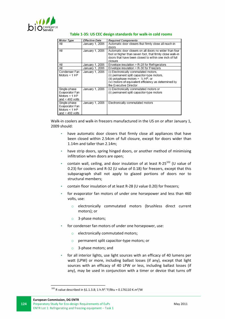
124
European Commission, DG ENTR
Preparatory Study for Eco-design Requirements of EuPs
ENTR Lot 1: Refrigerating and freezing equipment – Task 1
May 2011
Table 1-35: US CEC design standards for walk-in cold rooms
Walk-in coolers and walk-in freezers manufactured in the US on or after January 1,
2009 should:
• have automatic door closers that firmly close all appliances that have
been closed within 2.54cm of full closure, except for doors wider than
1.14m and taller than 2.14m;
• have strip doors, spring hinged doors, or another method of minimising
infiltration when doors are open;
• contain wall, ceiling, and door insulation of at least R-25102 (U value of
0.23) for coolers and R-32 (U value of 0.18) for freezers, except that this
subparagraph shall not apply to glazed portions of doors nor to
structural members;
• contain floor insulation of at least R-28 (U value 0.20) for freezers;
• for evaporator fan motors of under one horsepower and less than 460
volts, use:
o electronically commutated motors (brushless direct current
motors); or
o 3-phase motors;
• for condenser fan motors of under one horsepower, use:
o electronically commutated motors;
o permanent split capacitor-type motors; or
o 3-phase motors; and
• for all interior lights, use light sources with an efficacy of 40 lumens per
watt (LPW) or more, including ballast losses (if any), except that light
sources with an efficacy of 40 LPW or less, including ballast losses (if
any), may be used in conjunction with a timer or device that turns off
102
R value described in §1.1.3.8; 1 h.ft².°F/Btu = 0.176110 K.m²/W
May 2011
European Commission, DG ENTR
Proposal for Preparatory Study for Eco-design Requirements of EuPs
ENTR Lot 1: Refrigerating and freezing equipment – Task 1
125
the lights within 15 minutes of when the walk-in cooler or walk-in
freezer is not occupied by people.
Walk-in coolers equipped with transparent reach-in doors and walk-in freezers
equipped with transparent reach-in doors and manufactured on or after January 1,
2009 shall also meet the following design standards:
• transparent reach-in doors for walk-in freezers and windows in walk-in
freezer doors shall be of triple-pane glass with either heat-reflective
treated glass or gas fill;
• transparent reach-in doors for walk-in coolers and windows in walk-in
cooler doors shall be either:
1. double-pane glass with heat-reflective treated glass and gas fill; or
2. triple-pane glass with either heat-reflective treated glass or gas fill;
3. if the appliance has an antisweat heater;
• without antisweat heat controls, the appliance shall have a total door
rail, glass and frame heater power draw of not more than 7.1 watts per
square foot (W/ft²) (0.66 W/m2) 103 of door opening (for freezers) and
3.0 W/ft² (0.28 W/m2) of door opening (for coolers);
• with antisweat heat controls, and where the total door rail, glass and
frame heater power draw is more than 7.1 W/ft² (0.66 W/m2) of door
opening (for freezers) and 3.0 W/ft² (0.28 W/m2) of door opening (for
coolers), the antisweat heat controls shall reduce the energy use of the
antisweat heater in a quantity corresponding to the relative humidity in
the air outside the door or to the condensation on the inner glass pane.
Testing requirements: Please see §1.3.3.13.
� US DOE proposed testing procedure for walk-in coolers and freezers104
The US DOE has been developing a proposal for evaluation methods for walk-in
cold rooms. Please see § 1.3.3.14.
1.4.3.2 UK ECA incentive scheme for cellar cooling equipment105
Cellar cooling equipment covers products that are specifically designed to
maintain, by means of a refrigeration system, an indoor environment at a
condition suitable for the storage of chilled beverages below +12°C.
The scheme covers three categories of cellar cooling equipment:
• Packaged units where all components mounted on one base for "through
the wall” installation.
• Split systems with the equipment supplied in two parts (evaporator and
condensing unit) to be connected on installation.
• Remote systems with equipment supplied in three parts (evaporator,
compressor/receiver, and condenser) to be connected on installation.
103 1 ft
2 = 0.093 m
2
104 www1.eere.energy.gov/buildings/appliance_standards/commercial/wicf.html
105 www.eca.gov.uk/etl/find/_P_Refrigeration/3.htm?tab=CriteriaPanel

126
European Commission, DG ENTR
Preparatory Study for Eco-design Requirements of EuPs
ENTR Lot 1: Refrigerating and freezing equipment – Task 1
May 2011
To be eligible, products must:
• Have a cooling capacity of between 2 kW and 12 kW at the standard rating
conditions for ambient air temperature of 32°C and a cellar air
temperature of +10°C.
• Either be a single packaged unit, or consist of two or three factory-built
sub-assemblies that are designed to be connected together during
installation.
• Conform with the requirements of EU Pressure Equipment Directive PED
97/23/EC.
Products must have a coefficient of performance (COP) equal to or greater than
the figures shown below.
Table 1-36: Performance requirements for ECA approval of cellar cooling
equipment
Testing is carried out in accordance with PAS 57:2003 with some amendments
designed to reduce variability of results of the test methodology106. These include:
• Setting one storage temperature for the equipment (+12°C) rather than
the PAS 57:2003 approach of having a temperature range (+10 to +12°C);
• measuring the temperature of the thermal mass to ensure that is
maintained below the rated storage temperature during and at the end of
the cooling capacity and energy consumption tests;
• setting the maximum permissible calorimeter room temperature, and air
on to the evaporator, at the equipment’s rated storage temperature
(+12°C), rather than the PAS 57:2003 approach of having a permissible
calorimeter room temperature range above a potential rated storage
temperature (+10 ±0.5°C), during the energy consumption test;
• ensuring that the temperature control cycle for the calorimeter room
during the energy consumption test ends at the same point as it started
at; and
• requiring the test results to be specified to two decimal places.
Specifically, the new requirements are:
Section 6.2 “Cooling capacity measurement”
The test period shall be at least 1 hour and at the end of the test period, the
temperature of the thermal mass must be at or below the temperature that it was
at when the test period started.
Section 6.3 “System energy consumption measurement”:
106
Source: ECA Scheme
May 2011
European Commission, DG ENTR
Proposal for Preparatory Study for Eco-design Requirements of EuPs
ENTR Lot 1: Refrigerating and freezing equipment – Task 1
127
System energy measurement conditions - room B temperature at 10 °C ± 2 °C.
Steady state conditions:
b) air on to the evaporator is maintained within the band 8 °C to 12 °C.
d) the thermal mass is maintained at a temperature of 10 °C ± 0.5 °C.
The temperature in test room B for the system efficiency test shall be 10 °C ± 2 °C,
with the average temperature during the test period being 10 °C ± 0.5 °C.
The test period shall be at least 2 hours and must end at the same point in the
temperature control cycle for room B that the test started at.
At the end of the test period, the temperature of the thermal mass must be at or
below the temperature that it was at when the test period started.
Section 6.4 “Conditions to be recorded”:
Section 6.4.2 “Temperature (°C), accuracy ± 0.5 °C of the:
Add “m) thermal mass at two locations (the closest location to, and furthest
location from, the air off the evaporator).”
Test reports must be submitted and contain a statement of achieved performance
at the required rating points and the information specified in section 8 of PAS
57:2003.
The following additional information shall be included in the test report:
• A copy of data (specified to two decimal places) recorded for both the
capacity and energy consumption tests.
• Thermal mass - type, temperature and quantity. Number and type of
containers used.
• Photograph(s) of the interior of Room B clearly showing the position of the
evaporator(s) and the thermal mass.
• Room A & B dimensions, insulation type and U value.
If the test report has not been prepared by an independent body, then evidence
must be provided that a representative sample of product test data has been
independently verified or crosschecked.
1.4.3.3 PQS Quality Assurance protocol E01/CR/FR-VP2
The document, published as guidance from the World Health Organisation, sets
out a Quality Assurance (QA) protocol for the installation of cold rooms and
freezer rooms. Combination cold and/or freezer rooms are required to comply
with all specifications for both cold room and freezer rooms. It is stated that the
assessment should be conducted by the customer, or their designated QA
assessor.
The interesting aspect of this for walk-in cold rooms is the “Holdover test”, a
simple test procedure for the insulated enclosure whereby the electricity supply is
cut off and the period required for the internal temperature to rise to +10°C (for
cold rooms, or -10°C for freezer rooms) from normal operating temperature is
recorded (BS EN 4376-1:1991 is referenced within the documentation – see
§1.3.3.7).

128
European Commission, DG ENTR
Preparatory Study for Eco-design Requirements of EuPs
ENTR Lot 1: Refrigerating and freezing equipment – Task 1
May 2011
The door must remain closed throughout the test. External ambient air
temperature is also recorded throughout the test period. Compliance is proven if
the time period is equal to, or greater than, 8 hours.
Follow-up documentation and questionnaires are proposed to ensure evidence of
conformity, and provide the customer with explanatory details of the design and
questions to provoke good user practice.
The cost of the Holdover test is approximately €600107.
1.4.3.4 ATP agreement on the international carriage
The agreement details the following aspects of interest:
• Minimum requirements K coefficient values for the insulated enclosure:
The K coefficient of equipment of classes B, C, E and F shall in every case
be equal to or less than 0.40 W/m2.K (classes that are required to go down
to (or below) -10°C), and the other classes equal or lower to 0.70 W/m2.K.
• In the case of separate testing of insulated enclosure and refrigeration
system) a minimum required cooling capacity factor for the refrigeration
system: if the refrigerating system with all its accessories has undergone
separate test to determine its effective refrigerating capacity at the
prescribed reference temperatures, it will be acceptable if the effective
refrigerating capacity of the system in continuous operation exceeds the
heat loss through the walls for enclosure tested under the class
considered, multiplied by the factor 1.75.
• System of certification that incorporates “type approval” for similar
equipment (differentiating parameters that would not be permitted within
this approval are defined).
• Requirements for product marking.
• Requirements for product test reports.
The agreement states that checks for conformity with the standards prescribed
shall be made:
(a) before equipment enters into service;
(b) periodically, at least once every six years;
(c) whenever required by the competent authority.
Except in the cases provided for in appendix 2, sections 5 and 6 of the agreement,
the checks shall be made at a testing station designated or approved by the
competent authority of the country in which the equipment is registered or
recorded, unless, in the case of the check referred to in (a) above, a check has
already been made on the equipment itself or on its prototype in a testing station
designated or approved by the competent authority of the country in which the
equipment was manufactured.
A certificate of compliance with the standards shall be issued by the competent
authority of the country in which the equipment is to be registered. This
107
Source : GR Scott

May 2011
European Commission, DG ENTR
Proposal for Preparatory Study for Eco-design Requirements of EuPs
ENTR Lot 1: Refrigerating and freezing equipment – Task 1
129
documentation, or the required manufacturer’s plate, can be used by competent
authorities for identification during inspection.
Product ranges can be “Type Approved” to the required standards, after testing of
one unit, after which Type Approval certification lasts for 6 years. The competent
authority shall take steps to verify that production of other units is in conformity
with the approved type. For this purpose it may check by testing sample units
drawn at random from the production series. After 6 years, it is possible to renew
the certification for 3 year periods by having an in-service “K coefficient” test at an
approved ATP ‘Designated Station’ authorised by any country that is a signatory to
the agreement. If, in the course of the six-year period, the production series
exceeds 100 units, the competent authority shall determine the percentage of
units to be tested.
If a vehicle fitted with equipment does not have an ATP certificate, and no Type
Approvals have been issued, then the only option is to obtain a certificate by
having a ‘one off’ test at an approved test centre or at the owner’s site.
A unit shall not be regarded as being of the same type as the unit tested unless it
satisfies the following minimum conditions:
(i) If it is insulated equipment, the construction shall be comparable and, in
particular, the insulating material and the method of insulation shall be identical:
• the thickness of the insulating material shall be not less than that of the
reference equipment;
• the interior fittings shall be identical or simplified;
• the number of doors and the number of hatches or other openings shall
be the same or less; and
• the inside surface area of the body shall not be as much as 20% greater or
smaller.
(ii) ...
(iii) If it is mechanically refrigerated equipment, in which case the reference
equipment shall be either:...
(a) mechanically refrigerated equipment;
• the conditions set out in (i) above shall be satisfied; and
• the effective refrigerating capacity of the mechanical refrigeration
appliance per unit of inside surface area, under the same temperature
conditions, shall be greater or equal;
or (b) insulated equipment to which it is intended to have fitted, at a later date, a
mechanical refrigeration unit and which is complete in every detail but with the
refrigeration unit removed and the aperture filled, during the measurement of the
K coefficient, with close fitting panels of the same overall thickness and type of
insulation as is fitted to the front wall. In which case:
• the conditions set out in (i) above shall be satisfied; and
the effective refrigerating capacity of the mechanical refrigeration unit fitted to
insulated reference equipment shall be as defined.
130
European Commission, DG ENTR
Preparatory Study for Eco-design Requirements of EuPs
ENTR Lot 1: Refrigerating and freezing equipment – Task 1
May 2011
For further explanations of the agreement, including definitions and test
procedures, please see Annex 1-1, §1.14.

May 2011
European Commission, DG ENTR
Proposal for Preparatory Study for Eco-design Requirements of EuPs
ENTR Lot 1: Refrigerating and freezing equipment – Task 1
131
1.4.4. PROCESS CHILLERS
1.4.4.1 EU EUROVENT certification programme for liquid chilling packages
A EUROVENT certification scheme for liquid chilling packages exists.
Scope: this certification scheme applies to standard chillers used for air
conditioning (high temperature) and for refrigeration and covers three
applications:
• air conditioning, with leaving chilled water temperature between +2°C and
+15°C
• medium brine, with leaving brine temperature between +3°C and -12°C
• low brine, with leaving brine temperature between -8°C and -25°CA special
application for heating and cooling floors is also included.
They may operate with any type of compressor, but only electrically driven chillers
are included. All refrigerants are considered. Chillers may be air-cooled, water
cooled or evaporative cooled and with remote condensers. Reverse cycle chillers
shall be certified in cooling and in heating mode.
The following units are excluded from the programme: chillers powered by other
than electric motor drives, free cooling ratings, heat recovery and no reverse cycle
heat pumps and 60 Hz units.
The load rate and the performance criteria are only established for the cooling
capacity mode and for air conditioning chillers (packaged chillers working at high
temperature).
Requirements: Cooling capacity standard ratings are established at the Standard
Rating Conditions and verified by tests conducted in accordance with EN 14511.
Table 1-37 presents the capacity test Standard Rating Conditions that apply for
each application.
Table 1-37: Capacity test Standard Rating Conditions108
Temperatures
Cooling Heating
Application Code Evaporator Condenser Evaporator Condenser
Air conditioning
LCP/A../AC +12 to +7 35a 40/45 7(6)
Air / Water
LCP/W../AC +12 to +7 30/35 40/45 10/b
Water / Water
LCP/W../AC-MB +12 to +7 30/35 40/45 0/-3
Water / Brine
LCP/T../AC
+12 to +7 45-40c - - without
flasheconomiser
LCP/T../AC +12 to +7 45d - -
with flasheconomiser
Medium Brine
LCP/A../MB -5 to 0 35a 40/45 7(6)
Air / Water
LCP/W../MB -5 to 0 30/35 40/45 10/b
Brine / Brine
108
EUROVENT website: www.eurovent-certification.com

132
European Commission, DG ENTR
Preparatory Study for Eco-design Requirements of EuPs
ENTR Lot 1: Refrigerating and freezing equipment – Task 1
May 2011
Temperatures
Cooling Heating
or Brine / Water
LCP / T../MB
-5 to 0 45-40b - - without
flasheconomiser
LCP/T../MB -5 to 0 45d - -
with flasheconomiser
Low Brine
LCP/A../LB -15 to -10 35a 40/45 7(6)
Air / Water
LCP/W../LB
-15 to -10 30/35 40/45 10/b Brine / Brine
or Brine / Water
LCP/T../LB
-15 to -10 45-40b - - without
flasheconomiser
LCP/T../LB -15 to -10 45d - -
with flasheconomiser
Cool-heating Floor
LCP/A../CHF +18 to +23 35a 30/35 7(6)
Air / Water
LCP/W../CHF +18 to +23 30/35 30/35 10/b
Water / Water
LCP/W../CHF-MB
+18 to +23 30/35 30/35 0/-3 Brine / Brine
or Water / Brine
a = Measurement with the same water flow as in cooling mode, b = Dry bulb; c = The temperature corresponds to
compressor discharge pressure (bubble point) – liquid at expansion valve; d = The temperature corresponds to
compressor discharge pressure
The following characteristics of Liquid Chilling Packages are verified by tests at
Standard Rating Conditions and at one of the Application Rating Conditions
selected by Eurovent:
• cooling capacity
• energy efficiency ratio (EER)
• European Seasonal Energy Efficiency Ratio (ESEER109)
• water pressure drop at evaporator in cooling mode (units without pump)
• available pressure at evaporator in cooling mode (units with pump)
• water pressure drop at condenser in cooling mode
• A-weighted sound power level for air cooled chillers
• heating capacity for reverse cycle units
• coefficient of performance
• water pressure drop at evaporator in heating mode (units without pump)
• available pressure at evaporator in heating mode (units with pump)
• water pressure drop at condenser in heating mode
109
The European Seasonal Energy Efficiency Ratio is a weighed formula taking into account the
variation of EER with the load rate and the variation of air or water inlet condenser temperature.
ESEER is calculated as follows: ESEER = 0.03.EER100% + 0.33.EER75% + 0.41.EER50% +
0.23.EER25%

May 2011
European Commission, DG ENTR
Proposal for Preparatory Study for Eco-design Requirements of EuPs
ENTR Lot 1: Refrigerating and freezing equipment – Task 1
133
Energy Efficiency Classification of equipment: The purpose of Eurovent Energy
Efficiency Classes is to simplify the selection of the best units for each type of
chillers.
The classification (see Table 1-38) is entirely voluntary and is based on existing
chillers presented to certification. It is not related to any European Directive. The
energy efficiency of chillers is designated by “Eurovent Class A” or “Eurovent Class
B” in catalogues.
Table 1-38: Energy efficiency classification in cooling mode110
Part load certification: Chillers usually operate at full load only during a limited
period of time during a year. Therefore, the part load performance is closer to
reality and Eurovent decided to certify, together with full load efficiency, an
average annual part load efficiency of chillers.
A study111 partly funded by the European Commission through the SAVE
Programme was performed and an index called ESEER – Seasonal energy efficiency
ratio – has been defined. This index is similar to the IPLV (Integrated Part Load
Value) used by ARI in the US and takes into account several parameters in order to
establish an average use of chillers throughout Europe: weather data, building
load characteristics, operational hours etc. Therefore, the ESEER is a realistic tool,
much better than full load EER, to be used to compare average efficiency of two
chillers. However, it must be kept in mind that ESEER cannot be used to calculate
exact energy consumption for a particular use in a particular geographic position.
Neither ESEER nor IPLV give an indication of energy use in an industrial application,
but are instead relevant to air conditioning applications.
In order to compute ESEER the three part load EER for 25%, 50% and 75% load are
combined with full load EER. This global single figure is published in the Eurovent
Directory of certified products together with cooling capacity and power input for
standard conditions at full load. The operating temperatures and average
weighting coefficients for Europe are given in Table 1-39.
110
EUROVENT website: www.eurovent-certification.com 111
Energy Efficiency and Certification of Central Air Conditioners (EECCAC), Save Programme: Project
4.1031/P/00-009-2000, co-ordinator: ARMINES, April 2003

134
European Commission, DG ENTR
Preparatory Study for Eco-design Requirements of EuPs
ENTR Lot 1: Refrigerating and freezing equipment – Task 1
May 2011
Table 1-39: Operative ESEER temperatures and coefficients for air cooled and
water cooled chillers in Europe112
Stakeholders mentioned that the ESEER is soon to be replaced by SEER (as defined
in prEN 14825:2009).
1.4.4.2 UK ECA incentive scheme for packaged chillers (only for High temperature-
Air conditioning)
Eligibility Criteria: To be eligible, products must:
• Incorporate an electrically powered compressor (or compressors).
• Be one of the 16 specific categories of packaged chillers covered by the
ECA Scheme as detailed in table below, which are classified according to:
o Refrigeration capacity (in kW).
o Whether the product is air-cooled or water-cooled.
o Whether the product uses an integral or remote condenser.
o The heat transfer medium used (water or brine).
• Be subject to quality assurance procedures that ensure consistency of
performance between one production item and any other.
• Be CE Marked.
112
EUROVENT Website: www.eurovent-certification.com

May 2011
European Commission, DG ENTR
Proposal for Preparatory Study for Eco-design Requirements of EuPs
ENTR Lot 1: Refrigerating and freezing equipment – Task 1
135
Table 1-40: Performance thresholds for packaged chillers113
Where:
• EER = net cooling capacity (kW) / effective power input (kW) in cooling
mode.
• COP = net heating capacity (kW) / effective power input (kW) in heating
mode.
• The refrigeration capacity (kW) is determined in accordance with the
procedures and rating conditions in BS EN 14511:2004 or 2007 Air
conditioners, liquid chilling packages and heat pumps with electrically
driven compressors for space heating and cooling.
Required test procedures: All products must be tested in accordance with the
procedures and standard rating conditions laid down in BS EN 14511:2004 or 2007.
A detailed test report must be prepared for each individual product.
113
ECA Website, packaged chillers criteria: www.eca.gov.uk
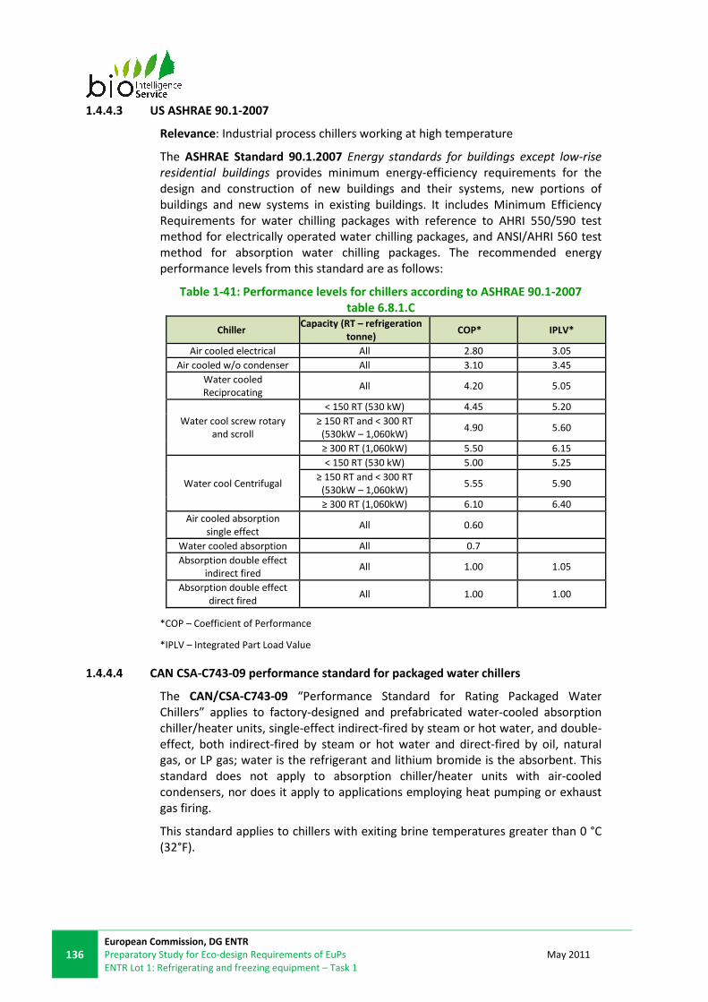
136
European Commission, DG ENTR
Preparatory Study for Eco-design Requirements of EuPs
ENTR Lot 1: Refrigerating and freezing equipment – Task 1
May 2011
1.4.4.3 US ASHRAE 90.1-2007
Relevance: Industrial process chillers working at high temperature
The ASHRAE Standard 90.1.2007 Energy standards for buildings except low-rise
residential buildings provides minimum energy-efficiency requirements for the
design and construction of new buildings and their systems, new portions of
buildings and new systems in existing buildings. It includes Minimum Efficiency
Requirements for water chilling packages with reference to AHRI 550/590 test
method for electrically operated water chilling packages, and ANSI/AHRI 560 test
method for absorption water chilling packages. The recommended energy
performance levels from this standard are as follows:
Table 1-41: Performance levels for chillers according to ASHRAE 90.1-2007
table 6.8.1.C
Chiller Capacity (RT – refrigeration
tonne) COP* IPLV*
Air cooled electrical All 2.80 3.05
Air cooled w/o condenser All 3.10 3.45
Water cooled
Reciprocating All 4.20 5.05
Water cool screw rotary
and scroll
< 150 RT (530 kW) 4.45 5.20
≥ 150 RT and < 300 RT
(530kW – 1,060kW) 4.90 5.60
≥ 300 RT (1,060kW) 5.50 6.15
Water cool Centrifugal
< 150 RT (530 kW) 5.00 5.25
≥ 150 RT and < 300 RT
(530kW – 1,060kW) 5.55 5.90
≥ 300 RT (1,060kW) 6.10 6.40
Air cooled absorption
single effect All 0.60
Water cooled absorption All 0.7
Absorption double effect
indirect fired All 1.00 1.05
Absorption double effect
direct fired All 1.00 1.00
*COP – Coefficient of Performance
*IPLV – Integrated Part Load Value
1.4.4.4 CAN CSA-C743-09 performance standard for packaged water chillers
The CAN/CSA-C743-09 “Performance Standard for Rating Packaged Water
Chillers” applies to factory-designed and prefabricated water-cooled absorption
chiller/heater units, single-effect indirect-fired by steam or hot water, and double-
effect, both indirect-fired by steam or hot water and direct-fired by oil, natural
gas, or LP gas; water is the refrigerant and lithium bromide is the absorbent. This
standard does not apply to absorption chiller/heater units with air-cooled
condensers, nor does it apply to applications employing heat pumping or exhaust
gas firing.
This standard applies to chillers with exiting brine temperatures greater than 0 °C
(32°F).

May 2011
European Commission, DG ENTR
Proposal for Preparatory Study for Eco-design Requirements of EuPs
ENTR Lot 1: Refrigerating and freezing equipment – Task 1
137
Table 1-42: Minimum Energy Efficiency Requirements for Packaged water
chillers114
Type Capacity range, kW (tons) COP115
IPLV116
Vapour compression
air-cooled with condenser < 528 (150) 2.80 3.05
≥ 528 (150) 2.80 3.05
air-cooled without condenser all 3.10 5.45
water-cooled, reciprocating all 4.20 5.05
water-cooled, rotary screw, scroll
< 528 (150) 4.45 5.20
≥ 528 (150) and ≤ 1,055 (300) 4.9 5.60
>1,055 (300) 5.5 6.15
water-cooled, centrifugal
< 528 (150) 5.00 5.25
≥ 528 (150) and ≤ 1,055 (300) 5.55 5.90
> 1,055 (300) 6.10 6.40
Absorption
single-effect absorption, air-cooled all 0.60 N/A
single-effect absorption, water-cooled all 0.70 N/A
double-effect absorption, indirect-fired all 1.00 1.05
double-effect absorption, direct-fired all 1.00 1.00
1.4.4.5 Australia/New Zealand water chillers MEPS
The MEPS covered by AS/NZS 4776.1:2008 concerns water chillers with a capacity
higher than 350kW. These MEPS are based on the EUROVENT certification
scheme, and apply to high temperature packaged water chillers.
Table 1-43: Minimum Energy Efficiency Requirements for Packaged water
chillers117
Capacity range, kWh Minimum COP Minimum IPLV
Air cooled Water cooled Air cooled Water cooled
<350 N/A N/A N/A N/A
350-499 2.70 5.00 3.70 5.50
500-699 2.70 5.10 3.70 6.00
700-999 2.70 5.50 4.10 6.20
1 000-1 499 2.70 5.80 4.10 6.50
>1 500 2.70 6.00 4.10 6.50
114
Canadian Office of Energy Efficiency: oee.nrcan-
rncan.gc.ca/regulations/packaged_water_chillers.cfm?attr=8 115
COP: Coefficient Of Performance is the ratio of the cooling capacity in watts [W] to the power
input value in watts [W] at any given set of Rating Conditions expressed in watts/watt [W/W] 116
IPLV: Integrated Part Load Value is a single number part-load efficiency figure of merit calculated
per the methods described in 5.3 of ARI 560 relative to Absorption Water Chilling And Water
Heating Packages 117
www.energyrating.gov.au/pubs/factsheet-chiller-meps.pdf. 2010

138
European Commission, DG ENTR
Preparatory Study for Eco-design Requirements of EuPs
ENTR Lot 1: Refrigerating and freezing equipment – Task 1
May 2011
1.4.5. REMOTE CONDENSING UNITS
1.4.5.1 UK ECA incentive scheme for air-cooled condensing units
Eligibility Criteria: To be eligible, products must:
• Operate with one or more identified standard refrigerants,
• Be a factory assembled unit that incorporates the following components
(at least):
o air-cooled refrigerant condenser,
o one or more electrical compressors
o a control systems for the compressor(s) and cooling fan(s)
• Conform to requirements to respect design, manufacture and testing
procedures.
• Have a COP greater than the values shown in Table 1-44.
Table 1-44: Performance thresholds for air-condensing units118
Temperature
category
Evaporating
temperature (Dew
point) (°C)
Ambient (condenser air-
on) temperature (°C)
Compressor suction
gas temperature (°C) COP threshold
HT units +5 +20 +20 ≥3.9
MT units -10 +20 +20 ≥2.8
LT units -35 +20 +20 ≥1.6
Where:
• COP = net heating capacity (kW) / effective power input (kW) in heating
mode.
• The refrigeration capacity (kW) is determined in accordance with the
procedures and rating conditions in BS EN 14511:2004 or 2007 Air
conditioners, liquid chilling packages and heat pumps with electrically
driven compressors for space heating and cooling.
Required test procedures: the performance can be tested by either of the two
following methods:
• Method A:
COP at relevant UK rating point (see Table 1-44) must be calculated with
the method used to generate its published performance over the standard
range of air temperature and evaporating temperature conditions.
The accuracy must be confirmed in the following way:
• performance should be determined at three test conditions within
+/-+1°C of the temperatures in Table 1-44;
• the level of uncertainty (at 95% confidence) in the calculated values
of COP must be determined using statistical methods.
118
ECA website, packaged chillers criteria: www.eca.gov.uk

May 2011
European Commission, DG ENTR
Proposal for Preparatory Study for Eco-design Requirements of EuPs
ENTR Lot 1: Refrigerating and freezing equipment – Task 1
139
The COP must exceed the threshold proposed in Table 1-44 by at least the
level of uncertainty in the calculations.
The test report must include:
• details of calculations method used to determine COP,
• a copy of the published performance data for the product,
• manufacturer’s design data for the product and key components
(including refrigerant, condenser fan motor type, and condenser),
• refrigerating capacity and COP of the compressor,
• where applicable, evidence of independent verification of the
compressor,
• copy of the compressor’s performance data by the manufacturer,
• test data from the product operating at full load:
o compressor’s inlet and outlet condensing and evaporating
pressures and dew temperatures,
o superheat and sub-cooling at the compressor’s inlet and
the unit’s outlet;
o condenser air inlet temperature,
o compressor input power in kW (where compressors are
not listed on the Energy Technology Product list, or their
performance independently verified)
• Method B:
When using this method, the performance of the product must be
demonstrated following the procedure from BS EN 13771-2:2007 (see
§1.3.5.1).
To obtain the refrigerant properties, one of the following standards must
be used:
• The US National Institute of Standards and Technology (NIST)
Standard reference database 23 thermodynamics and transport
properties of refrigerants and refrigerant mixtures database : 6.0 or
later.
• The ASERCOM properties database as defined in the ASERCOM
Compressor certification scheme, which is based closely on the
NIST database.
Data for a suction gas temperature of +20°C may be obtained by the
thermodynamic translation of data physically tested at 10K superheat119.
This is only applicable for high temperature only.
119
Superheating refers to the process of heating a substance over its boiling point. This is reached
under specific pressure conditions.

140
European Commission, DG ENTR
Preparatory Study for Eco-design Requirements of EuPs
ENTR Lot 1: Refrigerating and freezing equipment – Task 1
May 2011
The report shall include a statement of achieve performance according to
Table 1-44, and data on refrigerating capacity and COP at +32°C as
specified in EN 13215:2000.
1.4.6. EU ENVIRONMENTAL LEGISLATIONS
The following European environmental legislation applies at the product level.
1.4.6.1 European Directive 2002/96/EC on Waste Electrical and Electronic
Equipment (WEEE)
The WEEE Directive, effective 13 August 2005, requires separate collection,
treatment and recovery of electrical and electronic waste.
The purpose of the Directive is “as a first priority, the prevention of waste
electrical and electronic equipment (WEEE), and in addition, the reuse, recycling
and other forms of recovery of such wastes so as to reduce the disposal of waste”.
Scope: The Directive applies to electrical and electronic equipment120 falling under
the categories set out in Annex IA of the Directive.
According to the list of products provided in Annex IB, large cooling appliances,
refrigerators, freezers and other large appliances used for refrigeration,
conservation and storage of food fall under the category 1 “Large household
appliances” of Annex IA.
Targets for category 1 are set to:
• 75% of reuse and recycling of component, material and substance by an
average weight per appliance
• 80% of recovery (reuse and recycling + energy recovery) by an average
weight per appliance
Environmental aspects of the products that can be impacted by the standard:
End of life, material content.
In December 2008, the EU Commission published a proposal for revision of the
WEEE Directive. The main objectives of this revision are to set new collection and
treatment targets and to clarify the scope and definitions of current legislation.
1.4.6.2 European Directive 2002/95/EC on the Restriction of the use of certain
Hazardous Substances in electrical and electronic equipment (RoHS)
This RoHS Directive requires the substitution of various heavy metals (lead,
mercury, cadmium, and hexavalent chromium) and brominated flame retardants
(polybrominated biphenyls (PBB) and polybrominated diphenyl ethers (PBDE)) in
new electrical and electronic equipment put on the market from 1 July 2006.
Scope: The Directive applies to the categories of electrical and electronic
equipment that are covered by the WEEE directive except medical devices and
120
EEE: equipment which is dependent on electric currents or electromagnetic fields in order to
work properly and equipment for the generation, transfer and measurement of such currents and
fields designed for use with a voltage rating not exceeding 1 000 Volt for alternating current and
1 500 Volt for direct current

May 2011
European Commission, DG ENTR
Proposal for Preparatory Study for Eco-design Requirements of EuPs
ENTR Lot 1: Refrigerating and freezing equipment – Task 1
141
monitoring and control instruments. This Directive covers assemblies or
subassemblies of products.
According to the list of products provided in Annex IB, large cooling appliances,
refrigerators, freezers and other large appliances used for refrigeration,
conservation and storage of food fall under the category 1 “Large household
appliances” of Annex IA.
Environmental aspects of the products that can be impacted by the standard:
Material content.
The RoHS revision published in December 2008, foresees incorporation of
categories 8 and 9 of Annex IA (Medical products and monitoring and control
instruments) into RoHS. The proposal calls for most medical products to be
compliant by January 1, 2014, in vitro medical devices to be compliant by January
1, 2016, and industrial monitoring and control instruments by January 1, 2017.
1.4.7. LEGISLATION RELATED TO REFRIGERANT FLUIDS
1.4.7.1 European Regulation N°2037/2000 on Ozone Depleting Substances (ODS)
Following the Montreal Protocol, the EU implemented Regulation EC No.
2037/2000 on substances that deplete the ozone layer. It specifies an accelerated
HCFC (hydrochlorofluorocarbon) phase out schedule, compulsory recovery of CFCs
(chlorofluorocarbons) and HCFCs or ban of their use, and leak control. The
European schedule for the phase out of ozone depleting refrigerants is stricter
than the one established by the Montreal Protocol (and chosen by the US). This
triggered a transition in the choice of refrigerants used in the commercial
refrigeration industry.
From 2000 to 2002, the use of CFCs, the production of CFCs and the production of
equipment using such refrigerant were banned.
Since January 2001, the use of HCFCs in new systems in Europe for all types of
refrigeration equipment has been forbidden. Concerning HCFC production, the
regulation adopted the following provisions for actors selling these refrigerants,
and for their use:
• 01/01/2008: Reduction of sales by 85% with respect to 2001, lowering of
production by 65% with respect to 1997;
• 01/01/2010: Prohibiting of sales of virgin HCFCs;
• 01/01/2010: Prohibiting of the use of virgin HCFCs in the maintenance
and servicing of all equipment;
• 01/01/2014: Lowering of production by 80% with respect to 1997;
• 01/01/2015: Prohibiting of the use of recycled HCFCs in the maintenance
and servicing of all equipment;
• 01/01/2020: Lowering of production by 85% with respect to 1997;
• 01/01/2025: Prohibiting of production.
Recycled or reclaimed HCFCs may only be used for the servicing and maintenance
of refrigeration equipment until 2015 (as already foreseen in Regulation EC
N°2037/2000), only if they are recycled by the company operating the equipment

142
European Commission, DG ENTR
Preparatory Study for Eco-design Requirements of EuPs
ENTR Lot 1: Refrigerating and freezing equipment – Task 1
May 2011
or carrying out the servicing or maintenance. Furthermore, the revision introduces
amendments to the current legislation to facilitate the task of enforcing and
preventing the illegal trade or use of ODS in the EU. It also tightens current
provisions on the recovery and destruction of ODS contained in products and
equipment – the so-called ODS banks. The new provisions include a list of new
substances in the regulation for the first time and for which the reporting of
volumes produced and imported is required. The revision also bans the use of
methyl bromide for quarantine and pre-shipment as of March 2010.
1.4.7.2 European Regulation N° 842/2006 on certain fluorinated greenhouse gases
The European Regulation N° 842/2006 regulation entered into force on 4 July
2006 and applies from 4 July 2007.
The objective of this Regulation is to “contain, prevent and thereby reduce
emissions of the fluorinated greenhouse gases covered by the Kyoto Protocol”.
Scope: It applies to the fluorinated greenhouse gases listed in Annex I of the
regulation.
This Regulation addresses:
• the containment, the use, the recovery and the destruction of the
fluorinated greenhouse gases listed in Annex I of the regulation
• the labelling and disposal of certain products and equipment containing
those gases;
• the reporting of information on those gases
• the control of uses referred to in Article 8 of the regulation
• the prohibitions with respect to placing on the market of the products and
equipment referred to in Article 9 and Annex II of the regulation
• the training and certification of personnel and companies involved in certain
activities provided for by this regulation
According to Article 3, the following test intervals are given.
Table 1-45: Test intervals for refrigeration systems with varying refrigerant
charges
Test interval Quantity of fluorinated greenhouse gases
Every 12 months ≥ 3 kg
≥ 6 kg for labelled, hermetically sealed systems
≥ 30 kg for systems with automatic leakage detection system
Every 6 months ≥ 30 kg
≥ 300 kg for systems with leakage detection system
Every 3 months ≥ 300 kg and an obligation to install a leakage detection
system
After repair of a leak, the refrigerating systems shall be checked for leak tightness
within one month to ensure that the repair was effective.
Users, whose refrigerating systems have a refrigerant charge of more than 300 kg
are required to install leakage detection systems. These leakage detection systems
are checked at least once per year to ensure proper functioning. If a correctly
functioning and suitable leakage detection system is available, the frequency of
the above required control measures is halved.

May 2011
European Commission, DG ENTR
Proposal for Preparatory Study for Eco-design Requirements of EuPs
ENTR Lot 1: Refrigerating and freezing equipment – Task 1
143
The following table presents the schedule of prohibition of placing on the market
of products and equipments containing fluorinated greenhouse gases listed in the
Annex I of the regulation:
Table 1-46: Schedule of prohibition of placing on the market of fluorinated
greenhouse gases containing equipment
Fluorinated greenhouse gases Products and equipment Date of
prohibition
fluorinated greenhouse gases non-refillable containers 4 July 2007
hydrofluorocarbons and
perfluorocarbons
non-confined direct-evaporation systems
containing refrigerants 4 July 2007
perfluorocarbons fire protection systems and fire extinguishers 4 July 2007
fluorinated greenhouse gases windows for domestic use 4 July 2007
fluorinated greenhouse gases other windows 4 July 2008
fluorinated greenhouse gases Footwear 4 July 2006
fluorinated greenhouse gases Tires 4 July 2007
fluorinated greenhouse gases one component foams except when required to
meet national safety standards 4 July 2008
Hydrofluorocarbons Novelty aerosols 4 July 2009
1.4.7.3 DK statutory order 552121
This Danish legislation bans the use of HFC in foams and refrigeration systems
except with charges between 10 kg and 250 kg. This Order applies to HFCs,
perfluorocarbons (PFC) and sulphurhexafluoride (SF6) and sets a general ban on
new products containing these substances from June 1 2006. There are some
exemptions from this general ban. For instance, the ban on HFCs will come into
force for cooling equipment with HFC charges > 10 kg from 01.01.07 and the use of
HFC for service purposes is exempted from the Order.
1.4.7.4 Austria Ordinance No 447/2002
Amended by Ordinance No 139/2007: The Ordinance bans the placing on the
market and use of hydrofluorocarbons (HFCs), perfluorocarbons (PFCs) and
sulphur hexafluoride (SF6) greenhouse gases in certain equipment, units and
products, unless they are used for research, development and analytical purposes.
Concerning stationary applications, the bans apply only to small plug-in units with
a refrigerant charge of 150g or less and to stand alone equipment with a
refrigerant charge of 20 kg or more.
1.4.7.5 Norway - Tax and refund scheme for imported HFCs
This policy measure is a tax on imported HFCs and PFCs, which was introduced
explicitly as a greenhouse gas reduction measure. The special tax (Regulations no.
1451 of 11 December 2001) is set at 190.50 Norwegian Kroner (approximately 24
€) per tonne of CO2- equivalents and applies to both imports as well as national
production (although there is currently none) of HFC gases, whether in bulk or in
products. The tax, which is collected by the Norwegian Ministry of Finance, makes
121
Danish Ministry of the Environment website:
www.mst.dk/English/Chemicals/Legislation/Fact_sheets/Fachtsheet_no_46.htm

144
European Commission, DG ENTR
Preparatory Study for Eco-design Requirements of EuPs
ENTR Lot 1: Refrigerating and freezing equipment – Task 1
May 2011
the import price of the refrigerant higher, leading to a more restricted use of the
gas, and bringing alternatives within reach. The tax is coupled to a refund scheme.
As a result the tax for R404a is currently at approximately 82 €/kg and for R134a at
32€/kg.
A refund of taxes on HFCs and PFCs (Regulations no. 1060 of 30 June 2004) is paid
to stimulate the safe removal and disposal of refuse gas. The refund is disbursed
for the quantity of HFCs and PFCs that is delivered to an approved destruction
facility for destruction. The refund rates equal the differentiated tax rates for the
tax on HFCs and PFCs applicable at the time of delivery. The refund is administered
by the Ministry of Environment’s Pollution Control Authority (SFT).
1.4.8. ENERGY-EFFICIENCY AND USE LEGISLATION
This section presents the extent to which the components used in refrigerating
equipment are covered by existing legislation, and in particular Ecodesign
implementing measures.
As a general guideline, energy efficiency related components of the products
covered in the ENTR lot 1 study will be covered by the study as follows:
• If the component is placed separately on the market and then integrated in
refrigerating equipment (e.g. a pump bought for a remote unit):
o If Ecodesign measures covering the component are in place it is
then covered by the relevant Ecodesign measure
o If no specific Ecodesign measure is in place improvement solutions
for this component will be investigated in the study
• If the component is bought on the OEM (Original Equipment Manufacturer)
market and then integrated in a refrigerating equipment which is CE-
marked:
o If relevant Ecodesign measures are in place, the Ecodesign
measure on refrigerating equipment may require that components
comply with them
o If no specific Ecodesign measure is in force or covers the given
component (e.g. some motors used in refrigerating equipment do
not fall into the scope of the dedicated Ecodesign measure),
improvement solutions for this component will be investigated in
the study
1.4.8.1 EuP TREN Lot 13 – Legislation related to household refrigerating appliances
Ecodesign requirements for household refrigerating appliances have been
developed in the framework of the Ecodesign Directive 2009/125/EC based on a
preparatory study on domestic refrigerators and freezers (TREN Lot 13)122.
This Regulation establishes ecodesign requirements for the placing on the market
of electric mains-operated household refrigerating appliances with a storage
volume up to 1 500 litres.
122
TREN Lot 13 Website: www.ecocold-domestic.org/

May 2011
European Commission, DG ENTR
Proposal for Preparatory Study for Eco-design Requirements of EuPs
ENTR Lot 1: Refrigerating and freezing equipment – Task 1
145
• Generic ecodesign requirements (see Annex II.1 of the Regulation) apply to
wine storage appliances and household refrigerating appliances.
• Specific ecodesign requirement (see Annex II.2 of the Regulation) apply to
household refrigerating appliances with a storage volume equal to or higher
than 10 litres, and neither to wine storage appliances and nor to absorption-
type refrigerating appliances and other-type refrigerating appliances
belonging to Categories 4 to 9. The requirements are presented in the table
below.
Table 1-47: Specific ecodesign requirements for household refrigerating
appliances Appliance type Application date Energy Efficiency Index (EEI)
Compression-type refrigerating
appliances
1 July 2010 EEI < 55
1 July 2012 EEI < 44
1 July 2014 EEI < 42
Absorption-type and other-type
refrigerating appliances
1 July 2010 EEI < 150
1 July 2012 EEI < 125
1 July 2015 EEI < 110
The Energy Efficiency Index of household refrigerating appliances is calculated in
accordance with the procedure described in Annex IV of the Regulation.
1.4.8.2 EuP TREN Lot 11 – Electric motors
Ecodesign requirements for electric motors have been developed in the
framework of the Ecodesign Directive 2009/125/EC based on the TREN Lot 11
preparatory study123, covering:
• Electric motors 1-150kW
• Water pumps (in commercial buildings, drinking water pumping, food
industry, agriculture)
• Circulators in buildings
• Ventilation fans (non-residential buildings)
So far, ecodesign requirements have only been put in place for electric motors and
circulators. Requirements for fans and water pumps are under development.
Motors
Minimum efficiency requirements have been established for electric motors in
Commission Regulation (EC) No 640/2009 of 22 July 2009 implementing Directive
2005/32/EC of the European Parliament and of the Council with regard to
ecodesign requirements for electric motors, including electric motors equipped
with variable speed drives, and motors integrated into other products – apart from
motors completely integrated into a product (for example gear, pump, fan or
compressor) of which the energy performance cannot be tested independently
from the product.
The motors falling under the scope of the Ecodesign requirements are electric
single-speed, three-phase 50 Hz or 50/60 Hz, squirrel cage induction motor, from
0.75 to 175 kW that:
• have 2-6 poles;
123
TREN Lot 11 Website: www.ecomotors.org/

146
European Commission, DG ENTR
Preparatory Study for Eco-design Requirements of EuPs
ENTR Lot 1: Refrigerating and freezing equipment – Task 1
May 2011
• have a rated voltage of UN up to 1000 V;
• have a rated output PN between 0.75 kW and 375 kW; and
• is rated on the basis of continuous duty operation.
The EC ecodesign requirements for motors (nominal minimum efficiencies) are set
out in Annex I of the draft commission regulation.
The regulation is therefore not applicable to products or components covered in
ENTR Lot 1, as motors are either small and single-phase (for use as fans) or
integrated into hermetic compressors.
Fans
The possible ecodesign requirements for fans (minimum energy performance
requirements) are set out in Annex I of the working document on “possible
ecodesign requirements for ventilation fans”, and are proposed to cover fans from
125W to 500kW across the following types:
• Axial fan
• Centrifugal forward curved fan and centrifugal radial bladed fan
• Centrifugal backward curved fan without housing
• Centrifugal backward curved fan with housing
• Mixed flow fan
• Cross flow fan
Although minimum efficiency requirements have been established for electric
motors, including those that are part of a motor-fan system, most fans covered by
the fans Regulation are used in combination with motors not covered by
Regulation (EC) No 640/2009.
Regarding coverage of fans integrated into other products, the working document
on proposed regulation of these products under Directive 2009/125/EC states:
“Many fans are integrated in other products without being separately placed on
the market or put into service within the meaning of Article 5 of Directive
2009/125/EC and of Directive 2006/42/EC of the European Parliament and of the
Council of 17 May 2006 on machinery, and amending Directive 95/16/EC. To
achieve the full cost-efficient energy-saving potential, fans within a 125 W – 500
kW power range integrated in other products should also be subject to the
provisions of this Regulation.”
This potential regulation therefore has relevance to products covered in ENTR Lot
1.
Pumps
The pumps falling under the scope of the possible Ecodesign requirements are:
• Single stage end suction water pumps with characteristics as follows:
o operating temperature between -10 and +120°C
o single suction, single impeller
o all efficiencies based on full (untrimmed) impeller

May 2011
European Commission, DG ENTR
Proposal for Preparatory Study for Eco-design Requirements of EuPs
ENTR Lot 1: Refrigerating and freezing equipment – Task 1
147
• Vertical multistage (MS) water pumps with characteristics as follows:
o operating temperature between -10 and +120°C
o vertical multistage pumps in in-line and ring section design
o 2900 rpm pumps only
o efficiency is measured and judged on the basis of a 3 stage pump
• Submersible multistage (MSS) pumps with nominal size 4” and 6”
1.4.8.3 Legislation related to the lighting system
The European Parliament and the Council of the European Union has issued a
Directive 2000/55/EC of the European Parliament and of the Council on energy
efficiency requirements for ballasts for fluorescent lighting put on the EU market,
implemented via Regulation 245/2009, applying to electric mains-operated
ballasts for fluorescent lighting sources as defined in European Standard EN
50294:1998.
Mandatory ecodesign requirements apply to products placed on the market
wherever they are installed, therefore such requirements cannot be made
dependent on the application in which the product is used (such as office lighting
or public street lighting).
1.4.8.4 Legislations related to tertiary and domestic lighting
Requirements for street lighting and office lighting are under development in the
framework of the Ecodesign Directive 2009/125/EC.
The draft legislation which was agreed by the Regulatory Committee in September
2008 sets requirements for linear and compact fluorescent lamps without
integrated ballast, for high intensity discharge lamps, and for ballasts and
luminaries able to operate such lamps. However, there are several limitations, for
instance very small HID lamps now increasingly popular in the retail sector are not
covered. Reflector lamps were covered under a separate piece of legislation on
directional light sources (TREN Lot 19: Part 2). The products foreseen to be
covered are used in streets and offices, but also in other applications (e.g.
industrial plants, shops, public buildings).
Depending on their specifications, the Ecodesign measure on commercial
refrigeration could require that lights placed separately on the market and then
integrated in refrigerating equipment comply with possible ecodesign
requirements of tertiary and domestic lighting.
1.4.8.5 European Directive on Electromagnetic Compatibility (ECM) 2004/108/EC
This Directive ensures that radio-communications operate in accordance with
International Telecommunication Union (ITU) radio regulations, and that electrical
supply networks and telecommunications networks, as well as equipment
connected to them, are protected against electromagnetic disturbance.
1.4.8.6 European Directive on construction products 89/106/EEC
Many manufacturers of insulating enclosures and panels used for walk-in cold
rooms provide these components without any refrigeration appliance (condensing
unit and/or evaporator). For these manufacturers, the CE mark and product

148
European Commission, DG ENTR
Preparatory Study for Eco-design Requirements of EuPs
ENTR Lot 1: Refrigerating and freezing equipment – Task 1
May 2011
certification is based on Directive EC 89/106. The Directive covers the
approximation of laws, regulations and administrative provisions of the Member
States relating to construction products. Within Annex I: Essential requirements, it
states:
The construction works and its heating, cooling and ventilation installations must
be designed and built in such a way that the amount of energy required in use shall
be low, having regard to the climatic conditions of the location and the occupants.
Essential requirements cover mechanical strength and stability, safety in the event
of fire, hygiene, health and the environment, safety in use, protection against
noise and energy economy and heat retention, as set out in Annex 1 to the
Directive. ETAG 021 (§1.3.3.2) has been developed for cold storage room and cold
storage building enclosure kits, and sets out methods for verification, assessment
and attestation of the products.
Only construction products that comply with the national standards transposing
the harmonised standards into a European technical approval or, in the absence of
such approvals, into national technical specifications complying with the essential
standards are eligible to bear the "CE" marking to ensure that all construction
works bearing the "CE" marking satisfy the essential requirements. It is up to the
manufacturers or their representatives established in the Community to attest,
either on the basis of their own resources or through an approved certification
body, that their products conform to the requirements. Products which have been
declared to conform with the Directive but which do not satisfy the essential
requirements and therefore pose a health and safety threat may be temporarily
withdrawn from the market by the Member States. Where non-conformity is
attributable to the technical specifications, to their application or to omissions
inherent therein, the Commission will decide, after consulting the Standing
Committee on Construction, whether the European or national technical
specification should or should not continue to enjoy presumption of conformity124.
1.4.9. HEALTH AND SAFETY LEGISLATION
The following pieces of legislation applies either to the product as an entity or to
different stages of the manufacture process.
1.4.9.1 European Directive 95/16/EC on Machinery, amended by 2006/42/EC
The Directive applies to machinery, defined as “an assembly, fitted with or
intended to be fitted with a drive system other than directly applied human or
animal effort, consisting of linked parts or components, at least one of which
moves, and which are joined together for a specific application”.
This Directive addresses essential health and safety requirements relating to the
design and construction of machinery. These requirements are provided in the
Annex IA of the Directive.
Effective 29 June 2006, this Directive had to be transposed at the member state
level before 29 June 2008. Before 29 December 2009, professional refrigeration
products were covered only by the Low Voltage Directive (including service
cabinets, horizontal refrigeration products and blast chillers).
124
ec.europa.eu/enterprise/sectors/construction/documents/legislation/cpd/index_en.htm

May 2011
European Commission, DG ENTR
Proposal for Preparatory Study for Eco-design Requirements of EuPs
ENTR Lot 1: Refrigerating and freezing equipment – Task 1
149
1.4.9.2 European Directive 2001/95/EC on General Product Safety
This Directive covers all the products “which are intended for consumers or likely,
under reasonably foreseeable conditions, to be used by consumers even if not
intended for them, and are supplied or made available in the course of a
commercial activity, and whether new, used or reconditioned”.
The Directive requires producers to place only safe products on the market, and to
provide information about risks. A safe product is defined as one which, “under
normal or reasonably foreseeable conditions of use including duration […] does
not present any risk or only the minimum risks compatible with the product's use,
considered to be acceptable and consistent with a high level of protection for the
safety and health of persons […]”. It obliges Member States to survey products on
the market.
This Directive is effective since 15/01/2004.
1.4.9.3 European Directive 73/23/EEC on Low Voltage Equipments (LVD)
According to the Directive, electrical equipment are defined as “any equipment
designed for use with a voltage rating of between 50 and 1 000 V for alternating
current and between 75 and 1 500 V for direct current, other than the equipment
and phenomena listed in Annex II” of the Directive.
This Directive covers all risks arising from the use of electrical equipment, including
not just electrical ones but also mechanical, chemical (such as, in particular,
emission of aggressive substances), health aspects of noise and vibrations, and
ergonomic aspects as far as ergonomic requirements are necessary to protect
against hazards in the sense of the Directive. The LVD lays down eleven “safety
objectives”, which represent the essential requirements of this Directive.
This Directive was amended by the Directive 93/68/EEC which adds that before
being placed on the market, the electrical equipment referred to in Article 1 must
have affixed to it the CE marking provided for in Article 10 attesting to its
conformity to the provisions of this Directive, including the conformity assessment
procedure described in Annex IV of the Directive.
1.4.9.4 Pressure Equipment Directive (PED) 1997/23/EC
This Directive, effective since 29/11/1999, applies to the design, manufacture and
conformity assessment of pressure equipment and assemblies with a maximum
allowable pressure PS greater than 0.5 bars. This Directive establishes that the
pressure equipment and the assemblies under the scope may be placed on the
market and put into serve only if, when properly installed and maintained and
used for their intended purpose, they do not endanger the health and safety of
persons. The Directive also establishes technical requirements for equipment,
listed in Annex I of the Directive. The compliment of the Directive is certified by
the CE Marking.
1.4.9.5 European Directive 98/83/EC on quality of water
The Directive 98/83/EC on quality of water intended for human consumption as
for objective to protect human health from the adverse effects of any
contamination of water intended for human consumption by ensuring that it is
wholesome and clean. Directive requirements will need to be taken into

150
European Commission, DG ENTR
Preparatory Study for Eco-design Requirements of EuPs
ENTR Lot 1: Refrigerating and freezing equipment – Task 1
May 2011
consideration for product categories using water for human consumption (i.e.
beverage machines, water dispensers and ice-makers).
1.4.9.6 Hazard Analysis Critical Control Point (HACCP)
HACCP is an internationally recognised and recommended system for food safety
management. It focuses on identifying the 'critical points' in a process where food
safety problems (or 'hazards') could arise and puts in place preventative measures.
This is sometimes referred to as 'controlling hazards'. Keeping records is also an
important part of HACCP systems125.
1.4.9.7 Summary of temperature and time constraints for cooked foodstuff
The parameters of the post-cooking process in different countries within the EU
are shown in the table below.
Table 1-48: Summary of chilling temperature and time constraints within the EU
Country Initial temperature (°C) Final temperature (°C) Time to reach final
temperature (min)
UK +70 +3 90
France +63 +10 180
Austria +75 +10 60
1.4.10. OTHER VOLUNTARY AGREEMENTS
1.4.10.1 EUROVENT certification programmes for refrigeration components
Eurovent also manages voluntary certification schemes for several refrigeration
components, such as fan coil units, ducted fan coil units, air coolers for
refrigeration, air cooled condensers, dry coolers, air handling units, and cooling
and heating coils.
1.4.10.2 ASERCOM certification of refrigerant compressors
The Association of European Refrigeration Compressor and Controls
Manufacturers (ASERCOM) also provides a performance certification programme
for refrigeration compressors. Its objective is to provide comparable and reliable
data using common test methods, thus providing common reference points for all
manufacturers.
1.4.10.3 DK demanufacture of refrigeration equipment126
Since January 2006, a standard for the “Demanufacture of Refrigeration
Equipment” was implemented in Danish law. The RAL quality mark GZ-728 is the
European standard for the demanufacturing of refrigeration devices. These quality
assurance and test specifications apply to the demanufacturing of waste
refrigeration equipment containing CFCs. The specifications cover the collection,
storage and processing of such equipment and the handling of the materials
recovered prior to re-use or disposal.
125
www.food.gov.uk/foodindustry/regulation/hygleg/hygleginfo/foodhygknow/ 126
RAL website: www.ral-online.org
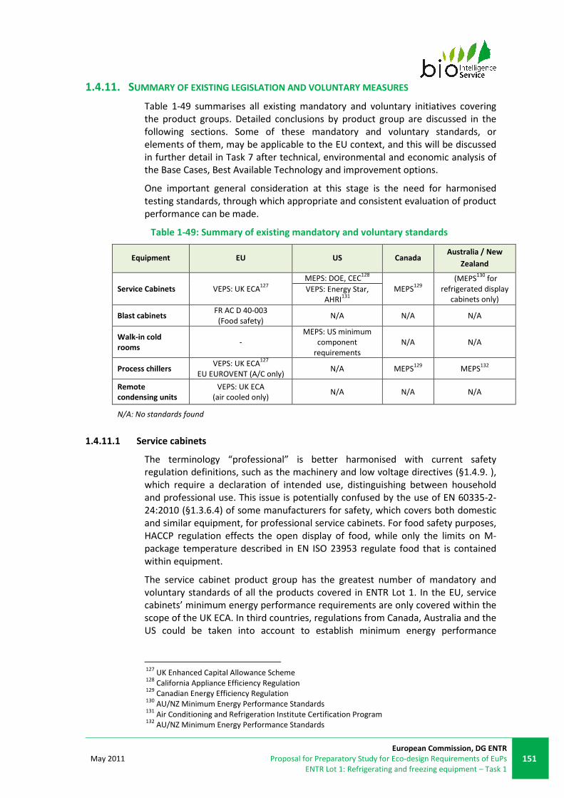
May 2011
European Commission, DG ENTR
Proposal for Preparatory Study for Eco-design Requirements of EuPs
ENTR Lot 1: Refrigerating and freezing equipment – Task 1
151
1.4.11. SUMMARY OF EXISTING LEGISLATION AND VOLUNTARY MEASURES
Table 1-49 summarises all existing mandatory and voluntary initiatives covering
the product groups. Detailed conclusions by product group are discussed in the
following sections. Some of these mandatory and voluntary standards, or
elements of them, may be applicable to the EU context, and this will be discussed
in further detail in Task 7 after technical, environmental and economic analysis of
the Base Cases, Best Available Technology and improvement options.
One important general consideration at this stage is the need for harmonised
testing standards, through which appropriate and consistent evaluation of product
performance can be made.
Table 1-49: Summary of existing mandatory and voluntary standards
Equipment EU US Canada Australia / New
Zealand
Service Cabinets VEPS: UK ECA127
MEPS: DOE, CEC128
MEPS129
(MEPS130
for
refrigerated display
cabinets only)
VEPS: Energy Star,
AHRI131
Blast cabinets FR AC D 40-003
(Food safety) N/A N/A N/A
Walk-in cold
rooms -
MEPS: US minimum
component
requirements
N/A N/A
Process chillers VEPS: UK ECA
127
EU EUROVENT (A/C only) N/A MEPS
129 MEPS
132
Remote
condensing units
VEPS: UK ECA
(air cooled only) N/A N/A N/A
N/A: No standards found
1.4.11.1 Service cabinets
The terminology “professional” is better harmonised with current safety
regulation definitions, such as the machinery and low voltage directives (§1.4.9. ),
which require a declaration of intended use, distinguishing between household
and professional use. This issue is potentially confused by the use of EN 60335-2-
24:2010 (§1.3.6.4) of some manufacturers for safety, which covers both domestic
and similar equipment, for professional service cabinets. For food safety purposes,
HACCP regulation effects the open display of food, while only the limits on M-
package temperature described in EN ISO 23953 regulate food that is contained
within equipment.
The service cabinet product group has the greatest number of mandatory and
voluntary standards of all the products covered in ENTR Lot 1. In the EU, service
cabinets’ minimum energy performance requirements are only covered within the
scope of the UK ECA. In third countries, regulations from Canada, Australia and the
US could be taken into account to establish minimum energy performance
127
UK Enhanced Capital Allowance Scheme 128
California Appliance Efficiency Regulation 129
Canadian Energy Efficiency Regulation 130
AU/NZ Minimum Energy Performance Standards 131
Air Conditioning and Refrigeration Institute Certification Program 132
AU/NZ Minimum Energy Performance Standards

152
European Commission, DG ENTR
Preparatory Study for Eco-design Requirements of EuPs
ENTR Lot 1: Refrigerating and freezing equipment – Task 1
May 2011
standards in EU133.These are compared below to provide an idea of the ranges and
variability of these standards, and some of the technical variations that might need
to be taken into account should EU mandatory measures be considered. However,
it must be noted that the limits set by different MEPS and VEPS are based on
different measurement methodologies134
. These methodologies can lead to
variation in resulting energy consumption figures of 5 to 10% for an identical
product. The graphs below, Figure 1-26 to Figure 1-29, are provided to
demonstrate different approaches, and should not be used for direct comparison
of the MEPS levels (where different test methodologies are used).
0.00
2.00
4.00
6.00
8.00
10.00
12.00
100 300 500 700 900 1100 1300 1500
TE
C (k
Wh
/da
y)
Net volume (litres)
Refrigerator MEPS and VEPS
HT; Plug-in; Vertical (US CEC)
HT; Plug-in; Any type (CAN EER)
HT; Plug-in; Vertical; 1-door (UK ECA)
HT; Plug-in; Vertical; 2-door (UK ECA)
HT; Plug-in; Counter and under-counter (UK ECA)
HT; Remote; Vertical or horizontal (US DOE and
CAN EER)
HT; Plug-in; Vertical; 0 <= net volume < 425 litres
(Energy Star)
HT; Plug-in; Any type (CEE Tier 2: US CEC +40%)
HT; Plug-in; Vertical; 425 <= net volume < 849
litres (Energy Star)
HT; Plug-in; Vertical; 849 <= net vlume < 1416
litres (Energy Star)
HT; Plug-in; Vertical; Net volume >= 1416 litres
(Energy Star)
HT; Plug-in; Chest (Energy Star)
Figure 1-26: Comparison of MEPS and VEPS for refrigerator (HT) service cabinets
133
The North-American approach to MEPS for refrigerated cabinets is a formula X*V + Y where
volume is defined in ft³. For detailed information on the US and Canadian MEPS for storage
cabinets, please refer to section 1.4.2.1 134
Hence, if one considers an appliance of 500l internal net volume, the limit of Energy Star might be
2,3 kWh/day while the limit of the UK ECA is 4 kWh/day, but an identical appliance may satisfy both
limits due to the different test methodologies used to assess the energy consumption. Source:
Electrolux.

May 2011
European Commission, DG ENTR
Proposal for Preparatory Study for Eco-design Requirements of EuPs
ENTR Lot 1: Refrigerating and freezing equipment – Task 1
153
0.00
5.00
10.00
15.00
20.00
25.00
30.00
100 300 500 700 900 1100 1300 1500
TE
C (k
Wh
/da
y)
Net volume (litres)
Freezer MEPS and VEPSLT; Plug-in; Vertical; 2-door (UK ECA)
LT; Plug-in; Net vilume >= 340 litres (CAN EER)
LT; Plug-in; Vertical; 1-door (UK ECA)
LT; Plug-in; Counter and under-counter (UK ECA)
LT; Plug-in; Net volume < 340 litres (CAN EER)
LT; Plug-in; Vertical (US CEC)
LT; Remote; Vertical (US DOE and CAN)
LT; Plug-in; Any type (CEE Tier 2: Energy Star/US CEC
+30%)
LT; Plug-in; Vertical; 0 <= net volume < 425 litres
(Energy Star)
LT; Plug-in; Vertical; 425 <= net volume < 849 litres
(Energy Star)
LT; Plug-in; Vertical; 849 <= net volume < 1416 litres
(Energy Star)
LT; Plug-in; Vertical; net volume >= 1416 litres
(Energy Star)
LT; Plug-in; Chest (Energy Star)
Figure 1-27: Comparison of MEPS and VEPS freezer (LT) service cabinets
0.00
2.00
4.00
6.00
8.00
10.00
12.00
14.00
16.00
18.00
20.00
100 300 500 700 900 1100 1300 1500
TE
C (k
Wh
/da
y)
Net volume (litres)
Refrigerator/freezer
MEPS
HT/LT; Plug-in;
refrigerator:freezer volume
50:50 (US CEC)
HT/LT; Plug-in;
refrigerator:freezer volume
50:50 (CAN EER)
Figure 1-28: Comparison of MEPS for refrigerator-freezer (HT/LT) service cabinets
In general, apart from the US CEC MEPS at low net volume, remote product
standards are more stringent than those for plug-in products. In addition, it is
interesting to note that different ranges of standards have been set for distinct

154
European Commission, DG ENTR
Preparatory Study for Eco-design Requirements of EuPs
ENTR Lot 1: Refrigerating and freezing equipment – Task 1
May 2011
ranges of product net volumes in the UK ECA and CAN EER schemes. Finally,
through examination of the US DOE and CEC MEPS, and the UK ECA VEPS, it
appears that there is significant variation in the differentiation of similar products
across operation temperatures by mandatory and voluntary schemes, as shown
below.
0.00
5.00
10.00
15.00
20.00
25.00
30.00
100 300 500 700 900 1100 1300 1500
TE
C (
kW
h/d
ay
)
Net volume (litres)
Refrigerator MEPS and VEPS
vs freezer MEPS and VEPS
HT; Remote; Vertical or horizontal (US DOE
and CAN EER)
HT; Plug-in; Vertical (US CEC)
HT; Plug-in; Vertical; 1-door (UK ECA)
HT; Plug-in; Vertical; 2-door (UK ECA)
HT; Plug-in; Counter and under-counter (UK
ECA)
LT; Remote; Vertical (US DOE and CAN)
LT; Plug-in; Vertical (US CEC)
LT; Plug-in; Vertical; 1-door (UK ECA)
LT; Plug-in; Vertical; 2-door (UK ECA)
LT; Plug-in; Counter and under-counter (UK
ECA)
Figure 1-29: Comparison of MEPS and VEPS for refrigerator and freezer service
cabinets
1.4.11.2 Blast cabinets
No legislation, minimal energy performance standards or agreements concerning
blast equipment have been identified.
1.4.11.3 Walk-in cold rooms
Currently there are no mandatory or voluntary minimum performance standards
for walk-in cold rooms, only minimum component requirements set by the US. A
testing standard is under development by the US DOE, and MEPS are due to be
defined in around 2013 (three years after final rule on testing standards is made).

May 2011
European Commission, DG ENTR
Proposal for Preparatory Study for Eco-design Requirements of EuPs
ENTR Lot 1: Refrigerating and freezing equipment – Task 1
155
1.4.11.4 Process chillers
MEPS from UK, USA, Canada, and Australia are summarised in Figure 1-30. In the
graph is shown how Canada and USA share the same level of strictness for chillers.
These standards are related only to packaged units. All of the values are reported
with respect to COP. The least demanding scheme is the UK ECA, which requires
half of the efficiency for equipment then its American equivalent.
The UK ECA scheme and standard AS/NZS 4776:2008 could be used as a model to
develop energy performance requirements for Packaged Chillers in the EU.
Nevertheless, their ranges of classification are different and any approach
developed would need to be homogenised. As for all other products within the
scope, it is very important to take into account the type of refrigerant for
environmental reasons. However, the energy performance of the equipment is
more related to the configuration than the employed refrigerant135.
2
2.5
3
3.5
4
4.5
5
5.5
6
6.5
0 200 400 600 800 1000 1200 1400 1600 1800 2000
CO
P (n
et c
oo
ling
ca
pac
ity
(k
W)
/ e
ffe
ctiv
e p
ow
er
inp
ut (
kW
) in
co
olin
g m
od
e)
Cooling capacity (kW)
MEPS and VEPS for ChillersECA - Split air-cooled chiller
(all compressors)
ECA - Packaged air-cooled
chiller (all compressors)
ECA - Water-cooled (all
compressors)
ASHRAE - Air-cooled w/o
condenser
ASHRAE - Water-cooled
reciprocating
ASHRAE - Centrifugal
ASHRAE - Screw
CAN - Air-cooled packaged
CAN - Air-cooled split
CAN - Water-cooled
reciprocating
CAN - Water-cooled
rotary/screw/scroll
CAN - Water-cooled
centrifugal
AS/NZ - Air-cooled
AS/NZ - Water-cooled
Base Case MT
BAT MT
Figure 1-30 MEPS and VEPS for Chillers from third countries and the UK
1.4.11.5 Remote condensing units
Only the UK ECA scheme establishes voluntary minimum standards, for air-cooled
remote condensing units. They are summarised in the figure and table below.
There is no minimum energy performance standard for remote condensing units.
135
Mark Ellis, consultation 2010.

156
European Commission, DG ENTR
Preparatory Study for Eco-design Requirements of EuPs
ENTR Lot 1: Refrigerating and freezing equipment – Task 1
May 2011
0
0,5
1
1,5
2
2,5
3
3,5
4
4,5
-35°C -10°C 5°C
CO
P (
ne
t co
oli
ng
ca
pa
city
(kW
) /
eff
ect
ive
po
we
r in
pu
t (k
W)
in
coo
lin
g m
od
e)
Temperature category
VEPS for air condensign units
UK ECA Scheme
Figure 1-31: VEPS for remote condensing units
Presented below are the UK ECA performance levels, with respective operating
conditions.
Table 1-50: VEPS for remote condensing units
Temperature Evaporating
temperature
Ambient
temperature
Compressor
suction gas
temperature
COP
threshold
High
temperature
units
+5°C 20°C 20°C >=3.9
Medium
temperature
units
-10°C 20°C 20°C >=2.8
Low
temperature
units
-35°C 20°C 20°C >=1.6
May 2011
European Commission, DG ENTR
Proposal for Preparatory Study for Eco-design Requirements of EuPs
ENTR Lot 1: Refrigerating and freezing equipment – Task 1
157
1.5. CONCLUSIONS FOR TASK 1
The preliminary discussions and scope presented in Task 1 outlined the key issues
and parameters related to the products relevant to the ENTR Lot 1.
Initial classifications for the product groups have been defined by category.
Accurate classifications are crucial to allow effective market data collection, which
in turn will ensure that the Base Cases (the current “average” products) to be
analysed in Task 4 are accurately reflecting the market.
Testing standards have been adapted for use with service cabinets, and others are
available for chillers and remote condensing units. Walk-in cold rooms and blast
cabinets are however lacking energy consumption testing standards in the EU,
although there is scope for development of these, based on the FR NF AC D40-003
for blast cabinets and the AHRI 1200/DOE approach for walk-in cold rooms.
The identification of the relevant legislation worldwide reveals that many third
countries have already developed obligatory minimum standards for some product
categories but that harmonised international or EU standards are relatively
lacking.
For some product categories, voluntary programmes exist in the EU whose
purpose is to provide a tool for comparison of competing products and also to set
any energy efficiency requirements (e.g. UK ECA). The US Energy Star experience
shows that companies offering Energy Star refrigerated display cabinets make up
over 90% of the market and about 1 330 products qualify in this range of products.
There are therefore clear avenues for development of both testing and
performance standards, which could be based upon existing initiatives. Existing
mandatory and voluntary minimum standards may provide a basis for EU MEPS
and will be further analysed in Task 7.

158
European Commission, DG ENTR
Preparatory Study for Eco-design Requirements of EuPs
ENTR Lot 1: Refrigerating and freezing equipment – Task 1
May 2011
ANNEXES

May 2011
European Commission, DG ENTR
Proposal for Preparatory Study for Eco-design Requirements of EuPs
ENTR Lot 1: Refrigerating and freezing equipment – Task 1
159
This page is left intentionally blank

160
European Commission, DG ENTR
Preparatory Study for Eco-design Requirements of EuPs
ENTR Lot 1: Refrigerating and freezing equipment – Task 1
May 2011
Annex 1-1: Additional standards related to refrigeration and freezing equipment
This annex provides a source of additional information, listing standards related to
products covered in ENTR Lot 1 that are not directly relevant to the study. System-
related standards will de described in the technical annex.
1.6. EN 153:2006
Relevance: Service cabinets
The EN 153:2006 (superseding EN 153:1995) “Methods of measuring the energy
consumption of electric mains operated household refrigerators, frozen food
storage cabinets, food freezers and their combinations, together with associated
characteristics” is the main EU harmonised standard used for the measurement of
the energy consumption of refrigerators and freezers. This standard was prepared
by European Committee for Standardisation/Technical Committee CEN/TC 44.
Scope: Household refrigerators, frozen food storage cabinets, food freezers and
similar equipments
This standard is used for household refrigeration appliances but can be used by
the industry to test commercial refrigeration appliances which are similar to
household refrigerators and freezers such as plug-in service cabinets (industry
common practice). Though, further specifications may be necessary for the testing
requirements of such products as they do not operate in a “home” (e.g. the
frequency of door opening might be an important parameter for service cabinets
as they are more intensively used than household appliances). The use of EN 153
has been superseded by EN ISO 23953, according to stakeholders.
Requirements: EN 153 proposes a test method to be applied and defines control
procedures for checking values declared by the manufacturers.
Regarding testing methods EN 153 references to the EN ISO 15502:2005 (see next
standard), but includes some modifications to conform its requirements to the EU
legislation on rational use of energy i.e. Directive 2003/66/EC, and in particular:

May 2011
European Commission, DG ENTR
Proposal for Preparatory Study for Eco-design Requirements of EuPs
ENTR Lot 1: Refrigerating and freezing equipment – Task 1
161
• in Clause 5 – Design, only clause 5.1 and 5.6 of EN ISO 15502 apply. In
order to enable direct comparison between all climate class appliances for
the checking of energy consumption, the test temperature is always set at
+25°C for all class (SN, N, ST, and T (see Table 1-51 for class description)
• the refrigerating appliance with a rated voltage within the range between
220V and 240V shall be tested at 230V ± 1% with a frequency of 50 Hz ±
1%
• a specific normative Annex C – “Rated characteristics and control
procedure”, was set, which has an informative nature in EN/ISO 15502,
and deals with the control procedure of the declared values, which is
fundamental for the verification of the compliance to any legislation on
cold appliances.
The main changes in EN 153:2006 compared to the previous 1995 edition are:
• the rated voltage to test the refrigerating appliances, changed from 220V
to 230V
• inclusion of a correction formula for the energy consumption measured
value, to be normalised at ambient temperature = +25°C; when possible
ambient temperature range is from +24.5°C to +25.5°C
• addition of a normative annex on built-in refrigerating appliances
• addition of reference to Directives 94/2/EC and 92/75/EEC
• editorial modifications to be consistent with EN ISO 15502
1.7. EN ISO 15502:2005 (CORRIGENDUM 1:2007)
Relevance: Service cabinets
The EN ISO 15502:2005 (corrigendum 1:2007) test method related to “Household
refrigerating appliances - Characteristics and test methods”, prepared by Technical
Committee ISO/TC 86, Refrigeration and air-conditioning, Subcommittee SC 5,
Testing and rating of household refrigeration appliances is the internationally
recognised standard which specifies the essential characteristics of household
refrigerating appliances, factory assembled and cooled by internal natural
convection or forced air circulation.
Scope: Household refrigerating appliances and similar appliances (e.g. plug-in
service cabinets)
This test method is applicable to plug-in service cabinets as these appliances are
very similar to household appliances (common practice in the industry). As
mentioned for EN ISO 153:2006, further specifications could be set for the testing
requirements for these products.

162
European Commission, DG ENTR
Preparatory Study for Eco-design Requirements of EuPs
ENTR Lot 1: Refrigerating and freezing equipment – Task 1
May 2011
Requirements: The EN ISO 15502:2005 standard describes the following
specifications:
• essential characteristics of household refrigerating appliances, factory
assembled, and cooled by internal natural convection or forced air
circulation:
o refrigerating appliances types
o compartments and sections
� fresh food compartment
� cellar compartment
� chill compartment
� ice-making compartment
� frozen food compartment
• one, two, or three star compartment
• food freezer compartment/four star
compartment
� two star section (part of a food freezer compartment or
cabinet, or three-star compartment or cabinet)
o physical aspects and dimensions
o definitions relating to performance characteristics, including:
� freezing capacity
� ice-making capacity
� defrost types
o definitions relating to refrigerating system
o symbols
o classification
� in climatic classes: SN, N, ST, T
Table 1-51: Climatic classes of Household refrigerating appliances (EN ISO 15502)
Class Symbol Ambient temperature range
(°C)
Extended temperate SN +10 to +32
Temperate N +16 to +32
Subtropical ST +16 to +38
Tropical T +16 to +43
� in refrigerator-freezer types: “type I” and “type II”
(depending in the number of user-adjustable temperature
control devices)
o materials, design and manufacture characteristics
o storage temperatures:

May 2011
European Commission, DG ENTR
Proposal for Preparatory Study for Eco-design Requirements of EuPs
ENTR Lot 1: Refrigerating and freezing equipment – Task 1
163
Table 1-52: Refrigerating appliances storage temperatures in °C (EN ISO 15502)
Storage temperature in °C
Fresh food
storage
compartment
Food freezer and
three-star
compartment/cabine
t
Two-star
compartmen
t / section
One-star
compartmen
t
Cellar
compartmen
t
Chill
compartmen
t
t1m, t2m,
t3m
Tm
a t*** t** t* tcc tcc
0 ≤t1m,
t2m, t3m
≤ 8
≤
+4 ≤-18
a ≤-12
a ≤-6 +8≤tcm≤+14 -2≤tcc≤+3
a as a result of a defrost cycle, the storage temperatures of frost free and/or adaptive defrost refrigeration appliances are permitted
to rise by no more than 3K during a period not greater than 4 hours or 20% of the duration of the operating cycle, whichever is the
shorter.
tcc instantaneous temperature value (cellar or chill compartment); tma arithmetic average of t1m, t2m, t3m
• test methods for the determination of
o linear dimensions, volumes and areas:
� linear dimensions (shall be measured to the nearest
millimetre
� volumes of compartments and sections (shall be
expressed to the nearest whole number of cubic
decimetres or of litres): gross volume, total storage
volume, storage volume of fresh-food storage, chill,
cellar, ice-making compartments; food freezer
compartments/cabinets and frozen-food storage
compartments/cabinets; two-star sections
� volumes of shelves and partitions
� storage shelf area
o air tightness of seals of doors, lids, and drawers
o mechanical strength of shelves and similar components
o storage temperatures
o water vapour condensation: to determine the extent of
condensation of water on the external surface of the cabinet
under specified ambient conditions (temperature and relative
humidity)
o energy consumption: to measure the energy consumption of
refrigerating appliances under specified test conditions,
calculated for a period of exactly 24h from the measured value,
and expressed in kilowatt-hours per 24h (kWh/24h), to two
decimal places.
o Temperature rise time: to check the time for the temperature rise
of test packages from -8°C to -9°C
o Freezing capacity of food freezers and food freezer
compartments, loaded with test packages
o Ice making capacity of appliance in the ice tray or in the
automatic ice-maker, in kilograms of produced in 24h (kg of
ice/24h)
• test conditions:
o ambient temperature and humidity
164
European Commission, DG ENTR
Preparatory Study for Eco-design Requirements of EuPs
ENTR Lot 1: Refrigerating and freezing equipment – Task 1
May 2011
� for checking the storage temperatures, the ambient
temperature shall be:
• +10°C and +32°C for appliances in class SN
• +10°C and +32°C for appliances in class N
• +10°C and +32°C for appliances in class ST
• +10°C and +32°C for appliances in class T
� For checking the energy consumption, temperature rise
time, freezing capacity and ice-making capacity of all cold
appliances the ambient temperature shall be +25°C for
class SN, N, ST and +32°C for class T
� for other tests: at temperature stated in the test
specifications
o installation of the test appliances
o test packages
o operating requirements of the test appliances
o measuring instruments
o final test report requirements
• type of marking and information to be included in the rating plate
• technical and commercial product information
• instructions for users
Following a formal request started in 2003 by some Member States, the ISO
technical management board agreed to transfer the responsibility for standards on
the performance and rating of household refrigerators and freezers from ISO to
IEC which was confirmed by IEC with AC/28/2006 in September 2006. A new Sub-
Committee SC 59M (Performance of electrical household and similar cooling and
freezing appliances) has been created within IEC TC59 (Performance of household
and similar electrical appliances), the Technical Committee already addressing
other home appliances.
1.8. EN 28960:1993 (ISO 8960:1991)
Relevance: Service cabinet
The EN 28960:1993 (ISO 8960:1991) standard related to “Refrigerators, frozen
food storage cabinets and food freezers for household and similar use –
Measurement of emission of airborne acoustical noise” is linked to the
international standard on noise measurement IEC 60704-1 with replacement or
additions to conform to the specificities of refrigerating and freezing appliances.
This standard is currently under revision.
1.9. ANSI/ARI 420-2008
The ANSI/ARI 420-2008 standard “Performance rating of forced-circulation free-
delivery unit coolers for refrigeration” establishes for forced-circulation free-
delivery unit coolers for refrigeration: definitions; test requirements; rating
requirements; minimum data requirements for Published Ratings; marking and
nameplate data; and conformance conditions.
Scope: This standard applies to factory-made, Forced-Circulation, Free-Delivery
Unit Coolers, operating with a Volatile Refrigerant fed by either direct expansion
or liquid overfeed at wet and/or dry conditions.

May 2011
European Commission, DG ENTR
Proposal for Preparatory Study for Eco-design Requirements of EuPs
ENTR Lot 1: Refrigerating and freezing equipment – Task 1
165
Exclusion: This standard does not apply to air-conditioning units used primarily for
comfort cooling for which testing methods are given in other standards, unit
coolers operating at latent load conditions with refrigerant saturation temperature
< 32 ºF (0.0 ºC) to prevent frost, unit coolers installed in or connected to ductwork,
unit coolers using zeotropic refrigerants with glides greater than 2.0 ºF (1.1 ºC),
field testing of unit coolers.
1.10. ANSI/ARI 530-2005
The ANSI/ARI 530-2005 standard “Rating of Sound and Vibration for Refrigerant
Compressors” establishes the rating of sound and vibration for refrigerant applies
to External-drive, Hermetic and Semi-Hermetic Refrigerant Compressors. In the
case of External-drive Refrigerant Compressors, the driving mechanism shall be
excluded from the sound and vibration measurements. However, for Semi-
Hermetic Refrigerant Compressors where compressors. It the driving mechanism is
an integral part of the compressor assembly, it shall be included in the
measurements.
1.11. ANSI/ARI 520-2004
The ANSI/ARI 520-2004 standard “Performance rating of positive displacement
condensing units” establishes, for positive displacement condensing units:
definitions; test requirements; rating requirements; minimum data requirements
for published ratings; operating requirements; marking and nameplate data and
conformance conditions.
Scope: This standard applies to electric motor driven, single and variable capacity
positive displacement condensing units for air-cooled, evaporatively-cooled, and
water-cooled refrigeration applications.
Exclusions: This standard does not apply to condensing units intended for use in
household refrigerators and freezers, automotive air-conditioners, dehumidifiers.
Test Requirements: The tests required for this standard shall be conducted in
accordance with ASHRAE Standard 23 (see ASHRAE standards).
1.12. ANSI/ARI 540-2004
The ANSI/ARI 540-2004 standard “Performance rating of positive displacement
refrigerant compressors and compressor units” establishes, for single and variable
capacity positive displacement refrigerant compressors and compressor units:
definitions; test requirements; rating requirements; minimum data requirements
for published ratings; operating requirements; marking and nameplate data and
conformance conditions.
Scope: This standard applies to electric motor driven, single and variable capacity
positive displacement refrigerant compressors and compressor units. This
standard also applies to the presentation of performance data for positive
displacement refrigerant compressors and compressor units for air-cooled,
evaporatively-cooled or water-cooled air-conditioning, heat pump and
refrigeration applications.

166
European Commission, DG ENTR
Preparatory Study for Eco-design Requirements of EuPs
ENTR Lot 1: Refrigerating and freezing equipment – Task 1
May 2011
Exclusions: This standard does not apply to compressors and compressor units
employing ammonia (covered in ARI Standard 510) and compressors and
compressor units intended for use in household refrigerators and freezers,
automotive air-conditioners and dehumidifiers
Test Requirements: The tests required for this standard shall be conducted in
accordance with ASHRAE Standard 23 (see ASHRAE standards).
Rating conditions: Table 1-53 and Table 1-54 present standard rating conditions
for compressors and compressor units respectively for commercial refrigeration
and air conditioners and heat pumps applications.

May 2011
European Commission, DG ENTR
Proposal for Preparatory Study for Eco-design Requirements of EuPs
ENTR Lot 1: Refrigerating and freezing equipment – Task 1
167
Table 1-53: Standard rating conditions for compressors and compressor units for
commercial refrigeration applications
Table 1-54: Standard rating conditions for compressors and compressor units
used in air conditioners and heat pumps
Rating requirements: General performance data, covering the operational
spectrum of the equipment, must be presented in tabular form and include:

168
European Commission, DG ENTR
Preparatory Study for Eco-design Requirements of EuPs
ENTR Lot 1: Refrigerating and freezing equipment – Task 1
May 2011
• Suction dew point temperature range, °F [°C]
• Discharge dew point temperature range, °F [°C]
• Applicable superheat, °F [°C]
• Power Input, W [W]
• Compressor or Compressor Unit Efficiency, percent
• Refrigerant mass flow rate, lb/h [kg/s]
• Current, A [A]
• Refrigerant designation per ASHRAE Standard 34
Performance Data must be reported for the following conditions for the
compressor or compressor unit application depending on the usage intended
(extreme ends of the data may be omitted and not reported due to limits of
acceptable operation of the compressor or compressor unit as determined by the
manufacturer):
• Air-Conditioning (including heat pumps):
o -10°F to 55°F [-23°C to +13°C] suction dew point temperature in
+5°F [+3°C] increments
o +80°F to +140°F [+27°C to +60°C] discharge dew point
temperature in +10°F [+5.6°C] increments
o Return gas temperature per Table 1-54
• High Temperature (water coolers and walk-in coolers, for example):
o +20°F to +50°F [-7°C to +10°C] suction dew point temperature in
+5°F [+3°C] increments
o +80°F to +140°F [+27°C to +60°C] discharge dew point
temperature in +10°F [+5.6°C] increments
o Return gas temperature per Table 1-53
• Medium Temperature (service cabinets, for example):
o -10°F to +32°F [-23°C to 0°C] suction dew point temperature in
+5°F [+3°C] increments
o +80°F to +140°F [+27°C to +60°C] discharge dew point
temperature in +10°F [+5.6°C] increments
o Return gas temperature per Table 1-53
• Low Temperature (freezer cases, for example):
o -40°F to +10°F [-40°C to -12°C] suction dew point temperature in
+5°F [+3°C] increments
o +80°F to +140°F [+27°C to +60°C] discharge dew point
temperature in +10°F [+5.6°C] increments
o Return gas temperature per Table 1-53
1.13. ISO 5149:1993
International standard ISO 5149:1993 (not a standard endorsed by any of the
European Standards Bodies) “Mechanical refrigerating systems used for cooling
and heating – safety requirements”.
Scope: All types of refrigerating systems in which the refrigerant is evaporated and
condensed in a closed circuit, including heat pumps and absorption systems,
except for systems using water or air as the refrigerant. It is applicable to new

May 2011
European Commission, DG ENTR
Proposal for Preparatory Study for Eco-design Requirements of EuPs
ENTR Lot 1: Refrigerating and freezing equipment – Task 1
169
refrigerating systems, extensions and modifications of already existing systems,
and for used systems.
Requirements: This standard specifies the requirements relating to the safety of
persons and property for the design, construction, installation and operation of
refrigerating systems. It gives a classification of the refrigerating systems.
1.14. ATP AGREEMENT
1.14.1. INTRODUCTION
As described in §1.3.3.10 and §1.4.3.4, ATP is a multi-lateral agreement for
overland cross-border carriage of perishable foodstuffs. It ensures that vehicles
used for this carriage meet agreed international standards, which apply to the
bodywork (insulating box) and refrigeration systems.
Published by the United Nations, includes: the terms of the agreement and a list of
signatories; definitions and classifications of equipment; provisions relating to the
checking for compliance; methods and procedures for measuring the insulating
capacity and the efficiency of the refrigeration system; requirements for the
monitoring of air temperature during use; requirements for food sampling during
use; and temperature requirements for various chilled foodstuff.
1.14.2. DEFINITIONS
Insulated equipment. Equipment of which the body is built with insulating walls,
doors, floor and roof.
K coefficient. The overall heat transfer coefficient (K coefficient) of the insulated
equipment.
IN = Normally insulated equipment
IR = Heavily insulated equipment
Mechanically refrigerated equipment. Insulated equipment either fitted with its
own refrigerating appliance, or served jointly with other units of transport
equipment by such an appliance (fitted with either a mechanical compressor, or an
"absorption" device, etc.). 6 classes of refrigerating equipment (A to F)
aredescribed, able to maintain temperature below a certain maximum (or within a
specific range), with a mean external ambient temperature of +30°C.
Refrigeration unit. Packaged refrigeration system.
WO = Refrigerating capacity of a refrigeration unit when the evaporator is free
from frost
Ti = inside temperature
1.14.3. REQUIREMENTS
The mechanically refrigerated equipment shall be capable, with a mean outside
temperature of + 30 °C, of lowering the temperature Ti inside the empty body to,
and thereafter maintaining it continuously in the following manner at:
• Class A: Ti may be chosen between + 12 °C and 0 °C inclusive;

170
European Commission, DG ENTR
Preparatory Study for Eco-design Requirements of EuPs
ENTR Lot 1: Refrigerating and freezing equipment – Task 1
May 2011
• Class B: Ti may be chosen between + 12 °C and - 10 °C inclusive;
• Class C: Ti may be chosen between + 12 °C and - 20 °C inclusive.
• Class D: Ti is equal to or less than 0 °C;
• Class E: Ti is equal to or less than - 10 °C;
• Class F: Ti is equal to or less than - 20 °C.
In the case of classes A, B and C, any desired practically constant Ti (in conformity
with the standards defined above), while in the case of classes D, E and F a fixed
practically constant Ti (in conformity with the standards defined above).
The K coefficient of equipment of classes B, C, E and F shall in every case be equal
to or less than 0.40 W/m2.K (classes that are required to go down to (or below) -
10°C).
Testing stations shall be provided with the equipment and instruments necessary
to ensure that the K coefficient is determined with a maximum margin of error of
±10% when using the method of internal cooling and ±5% when using the method
of internal heating.
The overall coefficient of heat transfer (K coefficient), is such that the equipment is
assignable to one or other of the following two categories:
• IN specified by a K coefficient equal to or less than 0.70 W/m2.K;
• IR specified by a K coefficient equal to or less than 0.40 W/m2.K and by
sidewalls with a thickness of at least 45mm for transport equipment of a
width greater than 2.50m.
If the refrigerating appliance with all its accessories has undergone separately, to
the satisfaction of the competent authority, a test to determine its effective
refrigerating capacity at the prescribed reference temperatures, the transport
equipment may be accepted as mechanically refrigerated equipment without
undergoing an efficiency test if the effective refrigerating capacity of the appliance
in continuous operation exceeds the heat loss through the walls for the class
under consideration, multiplied by the factor 1.75.
For insulated bodies, the manufacturer’s plate shall be on the outside of the body.
The manufacturer’s plate shall show clearly and indelibly at least the following
particulars:
• Country of manufacture or letters used in international road traffic;
• Name of manufacturer or company;
• Model (figures and/or letters);
• Serial number;
• Month and year of manufacture.
Industry estimates that insulation will deteriorate at about 5% per annum,
therefore fuel costs will increase proportionally. In order to ensure the best
performance of the refrigeration equipment, maintenance should be carried out at
regular intervals, comprising of:
• Refrigerated unit servicing
• Temperature control thermostat calibration check
• Thermostat and temperature recorder calibration check
May 2011
European Commission, DG ENTR
Proposal for Preparatory Study for Eco-design Requirements of EuPs
ENTR Lot 1: Refrigerating and freezing equipment – Task 1
171
• Inspection of the bodywork for holes/damage. This should be promptly
repaired with the correct materials to ensure that insulation deterioration
due to moisture ingress is kept to a minimum.
• Inspection of door operation and seal condition to prevent the ingress of
dust, moisture and undesirable odours, as well as air leakage/temperature
loss.
1.14.4. TEST METHODS AND PROCEDURES (ANNEX 1, APPENDIX 2 OF THE AGREEMENT)
The following extracts and summaries of the requirements of the testing
procedures and methods are described (including relevant section numbers).
1.14.4.1 Definitions and general principles (Section 1)
The overall heat transfer coefficient (K coefficient) of the special equipment is
defined by the following formula:
K = W / S. ΔT
where W is either the heating power or the cooling capacity, as the case may be,
required to maintain a constant absolute temperature difference ΔT between the
mean inside temperature Ti and the mean outside temperature Te, during
continuous operation, when the mean outside temperature Te is constant for a
body of mean surface area S.
The mean surface area S of the body is the geometric mean of the inside surface
area Si and the outside surface area Se of the body:
S = √(Si . Se)
In determining the two surface areas Si and Se, structural peculiarities and surface
irregularities of the body, such as chamfers, wheel-arches and similar features,
shall be taken into account and shall be noted under the appropriate heading in
test reports; however, if the body is covered with corrugated sheet metal the area
considered shall be that of the plane surface occupied, not that of the developed
corrugated surface.
Temperature measuring points (1.3)
Describes the positions of 12 measuring points inside, and 12 measuring points
outside, of the insulated equipment are specified. The mean temperature of the
walls is the arithmetic mean of the mean of the outside temperatures and the
mean of the inside temperatures.
Steady state period and duration of test (1.7)
Describes the permitted variance of the mean outside and inside temperatures,
and the heating power (or cooling capacity) during the steady state period.
1.14.4.2 Insulating capacity of equipment (Section 2)
Section 2 sets out procedures for measuring the K coefficient of the insulated box.
Test method (2.1.2)
The K coefficient shall be measured in continuous operation either by the internal
cooling method or by the internal heating method.

172
European Commission, DG ENTR
Preparatory Study for Eco-design Requirements of EuPs
ENTR Lot 1: Refrigerating and freezing equipment – Task 1
May 2011
Describes the specifications for these two test options.
Test procedure (2.1.4)
In either case, the empty body shall be placed in an insulated chamber whose
mean temperature shall be kept uniform to within ±0.5K, to a level where the
temperature difference between the inside of the body and the insulated chamber
is 25°C ±2K, the average temperature of the walls of the body being maintained at
+20°C ±0.5K.
Also describes the air flow and other requirements.
Verification of the K coefficient (2.3.1)
If the test is solely to test the K coefficient, the tests can be stopped one the steps
as described above have been met.
Accuracy of the K coefficient (2.3.2)
Minimum margin of error is ±10% for internal cooling method and ±5% for internal
heating method.
1.14.4.3 Effectiveness of thermal appliances [applications] of the equipment (Section
3)
Section 3 sets out procedures for testing that the whole product (insulated box
plus refrigeration system) meets the performance requirements in terms of
achieving the given temperature classification.
Test method (3.2.1)
The empty body shall be placed in an insulated chamber whose mean temperature
shall be kept uniform, and constant to within ± 0.5K, at + 30°C. The mass of air in
the chamber shall be made to circulate as specified in section 2, and the
temperature measuring instruments protected against radiation shall be placed
inside and outside the body at the points specified in section 1.
Test procedure (3.2.2)
When the mean inside temperature of the body reaches the outside temperature
(+30°C), the doors, hatches and other openings shall be closed and the
refrigerating appliance and the inside ventilating appliances (if any) shall be
started up at maximum capacity. In addition, in the case of new equipment, a
heating appliance with a heating capacity equal to 35% of the heat exchanged
through the walls in continuous operation shall be started up inside the body
when the temperature prescribed for the class to which the equipment is
presumed to belong has been reached.
Criterion of satisfaction (3.2.5)
The test shall be deemed satisfactory if the refrigerating appliance is able to
maintain the prescribed temperature conditions during the said 12-hour periods,
with any automatic defrosting of the refrigerating unit not being taken into
account.
1.14.4.4 Procedure for measuring the effective refrigerating capacity of unit when
evaporator is free from frost (Section 4)
Section 4 sets out procedures for measuring refrigeration system cooling capacity.
May 2011
European Commission, DG ENTR
Proposal for Preparatory Study for Eco-design Requirements of EuPs
ENTR Lot 1: Refrigerating and freezing equipment – Task 1
173
General principles (4.1)
Refrigerating capacity, WO, of a unit when the evaporator is free from frost can be
calculated by attachment to either a calorimeter box or the insulated body of a
unit of transport equipment, operating continuously, and this can be described as:
Wo = Wj + U. ΔT
where: U is the heat leakage of the calorimeter box or insulated body, Watts/°C;
ΔT is the difference between the mean inside temperature Ti and the mean
outside temperature Te of the calorimeter or insulated body (K); Wj is the heat
dissipated by the fan heater unit to maintain each temperature difference in
equilibrium.
Test method (4.2)
Describes in detail the calculation methods, instrumentation (4.2.2), conditions
(4.2.3), and procedure (4.3) for calculation of the refrigeration unit capacity, both
for tests using the methodology described in section 2, or the calorimeter box
method (it is preferable to use a calibrated calorimeter box to obtain maximum
accuracy). However, it is sufficient to measure U directly, the value of this
coefficient being defined by the following relationship where:
U = W / ΔTm
where:
W is the heating power (in watts) dissipated by the internal heater and fans; ΔTm is
the difference between the mean internal temperature Ti and the mean external
temperature Te; U is the heat flow per degree of difference between the air
temperature inside and outside the calorimeter box or unit of transport
equipment measured with the refrigeration unit fitted.
The calorimeter box or unit of transport equipment (insulated box) is placed in a
test chamber, and both should be heavily insulated. If a calorimeter box is used, U.
Δ T should be not more than 35% of the total heat flow Wo.
Test result (4.4)
The refrigeration capacity for ATP purposes is that relating to the mean
temperature at the inlet(s) of the evaporator (temperature measuring instruments
protected against radiation).
1.14.4.5 Checking the insulating capacity of equipment in service (Section 5)
General examination of the equipment (5.1)
Checking the insulating capacity of equipment in service can be carried out
through the methods described in section 2, or a general examination which
investigates aspects such as the condition of the walls and insulation. An
examination of air-tightness (5.2) should also be carried out, with an observer
stationed inside the equipment, which has been placed in a brightly-illuminated
area (or other improved method).
Decisions (5.3)
If the condition of the equipment is judged as acceptable, it can be kept in service
in its class for no more than 3 years. If not, tests as described in section 2 should
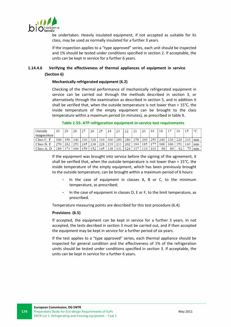
174
European Commission, DG ENTR
Preparatory Study for Eco-design Requirements of EuPs
ENTR Lot 1: Refrigerating and freezing equipment – Task 1
May 2011
be undertaken. Heavily insulated equipment, if not accapted as suitable for its
class, may be used as normally insulated for a further 3 years.
If the inspection applies to a “type approved” series, each unit should be inspected
and 1% should be tested under conditions specified in section 2. If acceptable, the
units can be kept in service for a further 6 years.
1.14.4.6 Verifying the effectiveness of thermal appliances of equipment in service
(Section 6)
Mechanically refrigerated equipment (6.2)
Checking of the thermal performance of mechanically refrigerated equipment in
service can be carried out through the methods described in section 3, or
alternatively through the examination as described in section 5, and in addition it
shall be verified that, when the outside temperature is not lower than + 15°C, the
inside temperature of the empty equipment can be brought to the class
temperature within a maximum period (in minutes), as prescribed in table X.
Table 1-55: ATP refrigeration equipment in-service test requirements
If the equipment was brought into service before the signing of the agreement, it
shall be verified that, when the outside temperature is not lower than + 15°C, the
inside temperature of the empty equipment, which has been previously brought
to the outside temperature, can be brought within a maximum period of 6 hours:
• In the case of equipment in classes A, B or C, to the minimum
temperature, as prescribed;
• In the case of equipment in classes D, E or F, to the limit temperature, as
prescribed.
Temperature measuring points are described for this test procedure (6.4).
Provisions (6.5)
If accepted, the equipment can be kept in service for a further 3 years. In not
accepted, the tests decribed in section 3 must be carried out, and if then accepted
the equipment may be kept in service for a further period of six years.
If the test applies to a “type approved” series, each thermal appliance should be
inspected for general condition and the effectiveness of 1% of the refrigeration
uinits should be tested under conditions specified in section 3. If acceptable, the
units can be kept in service for a further 6 years.

May 2011
European Commission, DG ENTR
Proposal for Preparatory Study for Eco-design Requirements of EuPs
ENTR Lot 1: Refrigerating and freezing equipment – Task 1
175
1.14.5. COMPLIANCE AND ENFORCEMENT
Checks for conformity with the standards shall be made:
(a) before equipment enters into service;
(b) periodically, at least once every six years;
(c) whenever required by the competent authority.
Except in the cases provided for in appendix 2, sections 5 and 6 of the agreement,
the checks shall be made at a testing station designated or approved by the
competent authority of the country in which the equipment is registered or
recorded, unless, in the case of the check referred to in (a) above, a check has
already been made on the equipment itself or on its prototype in a testing station
designated or approved by the competent authority of the country in which the
equipment was manufactured.
A certificate of compliance with the standards shall be issued by the competent
authority of the country in which the equipment is to be registered. This
documentation, or the required manufacturer’s plate, can be used by competent
authorities for identification during inspection.
Product ranges can be “Type Approved” to the required standards, after testing of
one unit, after which Type Approval certification lasts for 6 years. The competent
authority shall take steps to verify that production of other units is in conformity
with the approved type. For this purpose it may check by testing sample units
drawn at random from the production series. After 6 years, it is possible to renew
the certification for 3 year periods by having an in-service “K coefficient” test at an
approved ATP ‘Designated Station’ authorised by any country that is a signatory to
the agreement. If, in the course of the six-year period, the production series
exceeds 100 units, the competent authority shall determine the percentage of
units to be tested.
If a vehicle fitted with equipment does not have an ATP certificate, and no Type
Approvals have been issued, then the only option is to obtain a certificate by
having a ‘one off’ test at an approved test centre or at the owner’s site.
A unit shall not be regarded as being of the same type as the unit tested unless it
satisfies the following minimum conditions:
(i) If it is insulated equipment, the construction shall be comparable and, in
particular, the insulating material and the method of insulation shall be identical:
• the thickness of the insulating material shall be not less than that of the
reference equipment;
• the interior fittings shall be identical or simplified;

176
European Commission, DG ENTR
Preparatory Study for Eco-design Requirements of EuPs
ENTR Lot 1: Refrigerating and freezing equipment – Task 1
May 2011
• the number of doors and the number of hatches or other openings shall
be the same or less; and
• the inside surface area of the body shall not be as much as 20% greater or
smaller.
(ii) ...
(iii) If it is mechanically refrigerated equipment, in which case the reference
equipment shall be either:...
(a) mechanically refrigerated equipment;
• the conditions set out in (i) above shall be satisfied; and
• the effective refrigerating capacity of the mechanical refrigeration
appliance per unit of inside surface area, under the same temperature
conditions, shall be greater or equal;
or (b) insulated equipment to which it is intended to have fitted, at a later date, a
mechanical refrigeration unit and which is complete in every detail but with the
refrigeration unit removed and the aperture filled, during the measurement of the
K coefficient, with close fitting panels of the same overall thickness and type of
insulation as is fitted to the front wall. In which case:
• the conditions set out in (i) above shall be satisfied; and
• the effective refrigerating capacity of the mechanical refrigeration unit
fitted to insulated reference equipment shall be as defined.

May 2011
European Commission, DG ENTR
Proposal for Preparatory Study for Eco-design Requirements of EuPs
ENTR Lot 1: Refrigerating and freezing equipment – Task 1
177
1.15. OTHER RELATED STANDARDS
• EN 13215:2000: Condensing units for refrigeration rating conditions,
tolerances and presentation of manufacturer’s performance data
• EN 12900:2005: Refrigerant compressors - Rating conditions, tolerances
and presentation of manufacturer's performance data
The purpose of this norm is to specify the rating conditions, tolerance and
method of presenting data for positive displacement refrigerant
compressors. Single stage and single and two stage compressors using
liquid for sub-cooling are included. The results obtained can be used as
comparative parameters between equipments.
• EN 14276-1:2006: Pressure equipment for refrigerating systems and heat
pumps - Part 1: Vessels - General requirements
• EN 13313:2001: Refrigerating systems and heat pumps - Competence of
personnel
• EN 12178:2003: Refrigerating systems and heat pumps - Liquid level
indicating devices - Requirements, testing and marking
• EN 13136:2001: Refrigerating systems and heat pumps - Pressure relief
devices and their associated piping - Methods for calculation
• EN 1861:1998: Refrigerating systems and heat pumps - System flow
diagrams and piping and instrument diagrams - Layout and symbols
• EN 12284:2003: Refrigerating systems and heat pumps - Valves -
Requirements, testing and marking
• EN 12900:2005: Refrigerant compressors - Rating conditions, tolerances
and presentation of manufacturer's performance data
• EN 12524:2000. Building materials and products. Hygrothermal properties.
Tabulated design values.
• ISO 6946:2007: Building components and building elements – Thermal
resistance and thermal transmittance – Calculation method
This document provides the calculation method for thermal properties od
building components and elements (walk-in cold rooms included). It also
states approximate method to be used in inhomogeneous layers.
• BS EN 14509:2006: Self-supporting double skin metal faced insulating
panels. Factory made products. Specifications
• CWA 15596:2006: The CEN Work Agreement CWA 15596:2006 defines the
“Code of practice on cleanability of commercial food equipment used in the
retail and catering sectors”. It is linked to the main standard on safety
requirements IEC 60335. CWA is not a standard in a formal document and
deals with cleanability, construction, not food safety standard.
178
European Commission, DG ENTR
Preparatory Study for Eco-design Requirements of EuPs
ENTR Lot 1: Refrigerating and freezing equipment – Task 1
May 2011
This page is left intentionally blank

May 2011
European Commission, DG ENTR
Proposal for Preparatory Study for Eco-design Requirements of EuPs
ENTR Lot 1: Refrigerating and freezing equipment – Task 1
179
Annex 1-2: Summary of data for selection of the Base Cases
The matrix below summarises previous data, no longer valid, used to prioritise the
refrigeration products for further analysis in Task 4 of ENTR Lot 1. Table 1-57
shows the updated data as per the results of this study. These figures indicated
that the products for further analysis as Base Cases, due to their significant energy
saving potentials, should be:
• Service cabinets.
• Blast cabinets.
• Walk-in cold rooms.
• Remote condensing units.
• Industrial process chillers.

180
European Commission, DG ENTR
Preparatory Study for Eco-design Requirements of EuPs
ENTR Lot 1: Refrigerating and freezing equipment – Task 4
January 2010
Table 1-56: Market and energy consumption figures for products in the scope of ENTR Lot 1
ENTR Lot 1Product
type
EU-27
sales
[units in
2008]
EU-27
stock
[units in
2008]
EU-27
sales
[units in
2020]
EU-27
stock
[units in
2020]
Estimated
average total
energy
consump. per
product
[kWh/year]
Approximate
lifetime (years
of sales to
replace stock)
[years]
Total stock
energy
consump.
TWh/year
(2008)
Total stock
energy
consump.
TWh/year
freeze scenario
(2020)
Estimated
average energy
saving
potential per
product [% in
2020]
Total stock
energy consump.
TWh/year with
energy savings
scenario (2020)
Estimated EU-
27 savings in
TWh/year in
2020
Product
Remote 39 744 326 016 44 023 362 162 4 500 8 1,47 1,63 25% 1,35 0,28
Plug-in 357 700 2 934 147 396 207 3 259 454 4 500 8 13,20 14,67 33% 11,37 3,29
Total 397 444 3 260 163 440 230 3 621 615 - - - - - -
Remote 250 000 1 550 000 276 913 1 722 050 6 750 6 10,46 11,62 21% 9,73 1,90
Plug-in 250 000 1 550 000 276 913 1 722 050 6 750 6 10,46 11,62 33% 8,69 2,94
Total 500 000 3 100 000 553 826 3 444 100 - - - - - -
Remote 22 072 380 415 24 808 422 593 15 100 16 5,74 6,38 31% 5,99 0,40
Remote +
PCU*22 072 380 415 24 808 422 593 15 100 16 5,74 6,38 39% 5,80 0,58
Plug-in 44 145 760 830 49 615 845 185 15 100 16 11,49 12,76 39% 11,62 1,15
Total 88 289 1 521 659 99 230 1 690 370 - - - - - -
Dessert and
beverage machines- 150 000 1 500 000 166 630 1 666 304 650 9 0,98 1,08 17% 0,97 0,11
Packaged 3 911 79 296 4 185 70 941 399 105 17 31,65 28,31 30% 26,68 1,63
Plant 391 7 930 419 7 094 399 105 17 3,16 2,83 30% 2,67 0,16
Total 4 302 87 226 4 604 78 035 - - - - - -
Bottled
water222 222 2 000 000 250 000 2 222 200 950 8 1,90 2,11 23% 1,79 0,32
Mains
water55 556 500 000 62 500 555 550 950 8 0,48 0,53 23% 0,45 0,08
Total 277 778 2 500 000 312 500 2 777 750 - - - - - -
Ice-makers - 120 148 985 756 133 081 1 095 052 5 000 8 4,93 5,48 10% 5,10 0,38
TOTAL - 1 797 220 15 917 767 2 038 990 17 662 115 - 102 105 - 92 13
*Packaged
condensing units
(PCU)
- 259 259 2 962 963 328 889 3 288 889 22 359 10 66,25 73,54 23% 63,38 10,16
Walk-in cold rooms
Industrial process
chillers
Water dispensers
Service Cabinets
Blast Cabinets

May 2011
European Commission, DG ENTR
Proposal for Preparatory Study for Eco-design Requirements of EuPs
ENTR Lot 1: Refrigerating and freezing equipment – Task 1
181
Table 1-57: Updated market and energy consumption figures for products in the scope of ENTR Lot 1
Product EU-27 sales
[units in 2008]
EU-27 sales*
[units in 2008]
EU-27 stock
[units in 2008]
EU-27 stock*
[units in 2008]
EU-27 sales
[units in 2020]
EU-27 sales*
[units in 2020]
ENTR Lot 1 2009 11/2010 2009 11/2010 2009 11/2010
Service Cabinets 397,444 397,444 3,260,163 3,260,163 440,230 440,230
Variation 0% 0% 0%
Blast Cabinets 500,000 173,655 3,100,000 1,331,197 553,826 224,155
Variation -65% -57% -60%
Walk-in cold rooms 88,289 88,289 1,521,659 1,521,659 99,230 99,230
Variation 0% 0% 0%
Industrial process chillers 4,302 6,441 87,226 80,929 4,604 8,105
Variation 50% -7% 76%
*Packaged condensing units (PCU) 631,101 599,759 5,260,581 5,243,301 644,986 502,614
Variation -5% 0% -22%
Dessert and beverage machines 150,000 1,500,000 166,630
Water dispensers 277,778 2,500,000 312,500
Ice-makers 120,148 985,756 133,081
Refrigeration compressors 253,000 1,771,000 253,076
Refrigeration condensors 50,600 354,200 39,316
* Weighted Base Case used. Weighted average considering market shares for products working at several temperature ranges
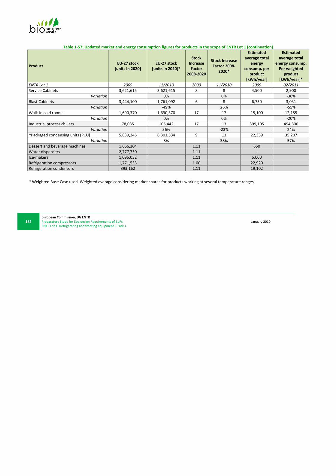
182
European Commission, DG ENTR
Preparatory Study for Eco-design Requirements of EuPs
ENTR Lot 1: Refrigerating and freezing equipment – Task 4
January 2010
Table 1-57: Updated market and energy consumption figures for products in the scope of ENTR Lot 1 (continuation)
Product EU-27 stock
[units in 2020]
EU-27 stock
[units in 2020]*
Stock
Increase
Factor
2008-2020
Stock Increase
Factor 2008-
2020*
Estimated
average total
energy
consump. per
product
[kWh/year]
Estimated
average total
energy consump.
Per weighted
product
[kWh/year]*
ENTR Lot 1 2009 11/2010 2009 11/2010 2009 02/2011
Service Cabinets 3,621,615 3,621,615 8 8 4,500 2,900
Variation 0% 0% -36%
Blast Cabinets 3,444,100 1,761,092 6 8 6,750 3,031
Variation -49% 26% -55%
Walk-in cold rooms 1,690,370 1,690,370 17 17 15,100 12,155
Variation 0% 0% -20%
Industrial process chillers 78,035 106,442 17 13 399,105 494,300
Variation 36% -23% 24%
*Packaged condensing units (PCU) 5,839,245 6,301,534 9 13 22,359 35,207
Variation 8% 38% 57%
Dessert and beverage machines 1,666,304 1.11 650
Water dispensers 2,777,750 1.11 -
Ice-makers 1,095,052 1.11 5,000
Refrigeration compressors 1,771,533 1.00 22,920
Refrigeration condensors 393,162 1.11 19,102
* Weighted Base Case used. Weighted average considering market shares for products working at several temperature ranges
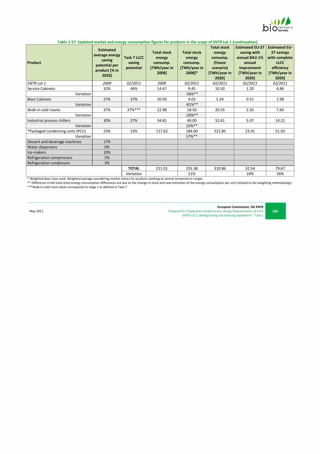
May 2011
European Commission, DG ENTR
Proposal for Preparatory Study for Eco-design Requirements of EuPs
ENTR Lot 1: Refrigerating and freezing equipment – Task 1
183
Table 1-57: Updated market and energy consumption figures for products in the scope of ENTR Lot 1 (continuation)
Product
Estimated
average energy
saving
potential per
product [% in
2020]
Task 7 LLCC
saving
potential
Total stock
energy
consump.
[TWh/year in
2008]
Total stock
energy
consump.
[TWh/year in
2008]*
Total stock
energy
consump.
(freeze
scenario)
[TWh/year in
2020]
Estimated EU-27
saving with
annual BAU 1%
annual
improvment
[TWh/year in
2020]
Estimated EU-
27 savings
with complete
LLCC
efficiency
[TWh/year in
2020]
ENTR Lot 1 2009 02/2011 2009 02/2011 02/2011 02/2011 02/2011
Service Cabinets 32% 46% 14.67 9.45 10.50 1.20 4.86
Variation -36%**
Blast Cabinets 27% 37% 20.93 4.03 5.34 0.51 1.98
Variation -81%**
Walk-in cold rooms 37% 37%*** 22.98 18.50 20.55 2.35 7.60
Variation -20%**
Industrial process chillers 30% 27% 34.81 40.00 52.61 5.07 14.21
Variation 15%**
*Packaged condensing units (PCU) 23% 23% 117.62 184.60 221.85 23.41 51.03
Variation 57%**
Dessert and beverage machines 17%
Water dispensers 0%
Ice-makers 10%
Refrigeration compressors 5%
Refrigeration condensors 3%
TOTAL 211.01 255.38 310.86 32.54 79.67
Variation 21% 10% 26%
* Weighted Base Case used. Weighted average considering market shares for products working at several temperature ranges
** Difference in the total stock energy consumption differences are due to the change in stock and new estimates of the energy consumption per unit (related to the weighting methodology)
***Walk-in cold room value corresponds to stage 1 as defined in Task 7
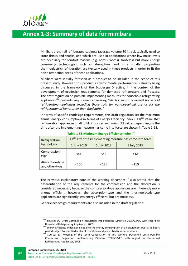
184
European Commission, DG ENTR
Preparatory Study for Eco-design Requirements of EuPs
ENTR Lot 1: Refrigerating and freezing equipment – Task 1
May 2011
Annex 1-3: Summary of data for minibars
Minibars are small refrigerated cabinets (average volume 30 litres), typically used to
store drinks and snacks, and which are used in applications where low noise levels
are necessary for comfort reasons (e.g. hotels rooms). Noiseless but more energy
consuming technologies such as absorption (and in a smaller proportion
thermoelectric) refrigeration are typically used in these products in order to fit the
noise restriction needs of these applications.
Minibars were initially foreseen as a product to be included in the scope of this
present study. However, this product’s environmental performance is already being
discussed in the framework of the Ecodesign Directive, in the context of the
development of ecodesign requirements for domestic refrigerators and freezers.
The draft regulation on possible implementing measures for household refrigerating
appliances136 presents requirements covering “electric mains operated household
refrigerating appliances including those sold for non-household use or for the
refrigeration of items other than foodstuffs.”
In terms of specific ecodesign requirements, this draft regulation set the maximum
annual energy consumptions in terms of Energy Efficiency Index (EEI)137 value that
refrigeration appliances shall fulfil. Proposed minimum EEI values depending on the
time after the implementing measure has come into force are shown in Table 1-58.
Table 1-58 Minimum Energy Efficiency Index137
Refrigeration
technology
EEI137 after the implementing measure has come into force
1 July 2010 1 July 2012 1 July 2015
Compression-
type <55 <44 <42
Absorption-type
and other-type <150 <125 <110
The previous explanatory note of the working document138 also stated that the
differentiation of the requirements for the compression and the absorption is
considered necessary because the compressor-type appliances are inherently more
energy efficient; however, the absorption-type and the thermoelectric-type
appliances are significantly less energy efficient, but are noiseless.
Generic ecodesign requirements are also included in the draft regulation:
136
Source: EC, Draft Commission Regulation Implementing Directive 2005/32/EC with regard to
Household Refrigerating Appliances, 2009 137
Energy Efficiency Index EEI is equal to the energy consumption of an equipment over a 48 hours
period subject to specified ambient conditions and prescribed number of doors. . 138
Source: EC, Meeting of the tenth Consultation Forum, Working Document on a Possible
Commission Regulation Implementing Directive 2005/32/EC with regard to Household
Refrigerating Appliances, 2008
May 2011
European Commission, DG ENTR
Proposal for Preparatory Study for Eco-design Requirements of EuPs
ENTR Lot 1: Refrigerating and freezing equipment – Task 1
185
“From 1 July 2010: For household refrigerating appliances, information shall be
provided in the instruction booklet provided by manufacturers concerning:
• the combination of drawers, baskets and shelves that result in the most
efficient use of energy for the appliance; and
• how to minimize the energy consumption of the household refrigerating
appliance in the use-phase.
From 1 July 2013:
• (a) The fast freezing facility, or any similar function achieved through
modification of the thermostat settings, in freezers and freezer
compartments, shall, once activated by the end-user according to the
manufacturer’s instructions, automatically revert to the previous normal
storage temperature conditions after no more than 72 hours. This
requirement does not apply to refrigerator-freezers with one thermostat
and one compressor which are equipped with an electromechanical
control board.
• (b) Refrigerator-freezers with one thermostat and one compressor which
are equipped with an electronic control board and can be used in ambient
temperatures below +16 °C according to the manufacturer’s instructions
shall be such that any winter setting switch or similar function
guaranteeing the correct frozen-food storage temperature is automatically
operated according to the ambient temperature where the appliance is
installed.
• (c) Household refrigerating appliances with a storage volume below 10
litres shall automatically enter in an operating condition with a power
consumption of 0.00 Watt after no more than 1 hour when empty. The
mere presence of a hard off switch shall not be considered sufficient to
fulfil this requirement.”
The annual market of the electric absorption refrigeration appliances is about
250,000 to 300,000 units, and the market for thermoelectric appliances is smaller.
As a comparison, there are about 18 million domestic compressor refrigerators.
� EN 732:1998
Relevance: Mini-bars
The safety and noise standard EN 732:1998 “Specifications for dedicated liquefied
petroleum gas appliances – Absorption refrigerators” applies to absorption
refrigerators for the technical characteristics, safety requirements, test methods
and marking of absorption refrigerating appliances using commercial butane and
propane (liquefied petroleum gases).
As mentioned, minibars have been included in the scope of the development of
implementing measures for household refrigerating appliances. Therefore, minibars
will not be discussed further in this study.
186
European Commission, DG ENTR
Preparatory Study for Eco-design Requirements of EuPs
ENTR Lot 1: Refrigerating and freezing equipment – Task 1
May 2011
Annex 1-4: Summary of data for wine storage appliances
Wine storage appliances can be used both in the residential and in the commercial
sectors. However, as for minibars, this product’s environmental performance is
already being discussed in the framework of the Ecodesign Directive, in the
context of the development of ecodesign requirements for domestic refrigerators
and freezers. For this category of appliances, generic and specific ecodesign
requirements have already been adopted:
• generic requirements: “From 1 July 2010: For wine storage appliances, the
following information shall be displayed in the instruction booklet provided
by manufacturers: ‘This appliance is intended to be used exclusively for the
storage of wine’.”
• Specific requirements are described in Table 1-58 above.
Wine storage appliances are therefore excluded from the scope of the present
study.

May 2011
European Commission, DG ENTR
Proposal for Preparatory Study for Eco-design Requirements of EuPs
ENTR Lot 1: Refrigerating and freezing equipment – Task 1
187
This page is left intentionally blank
188
European Commission, DG ENTR
Preparatory Study for Eco-design Requirements of EuPs
ENTR Lot 1: Refrigerating and freezing equipment – Task 1
May 2011
Annex 1-5: Summary of data for dessert and beverage machines
1.15.1.1 General product definition
This category refers to a range of products use to refrigerate, store, and dispense
beverages or desserts for consumption. Most common applications are ice cream
makers, milk-shake or slush machines and cold drink dispensers.
1.15.1.2 Existing product definitions
According to the International Dictionary of Refrigeration26, an ice-cream cabinet is
a refrigerated cabinet for retail storage of ice-cream. The ice-cream freezer is an
apparatus for freezing the “cream” mix into ice-cream. There are no other
equipment definitions in the category of dessert and beverage machines in the
dictionary.
1.15.1.3 Product description
In all the applications mentioned above, the temperatures are kept low by a
refrigeration process based on vapour-compression technology. Apart from the
refrigeration process (already explained in § 1.1.3.2), these products include
specific processes for each application:
• Ice cream makers: an ice cream maker has two functions; the mixture has
to be cooled, and during this cooling process, the mixture has to be
constantly churned to break up ice crystals that form and introduce some
air to the mixture so that the resultant ice cream will have a smooth and
creamy texture. Ice cream machines typically have an integral condensing
unit (plug-in). The condenser can either be water cooled or air cooled.
• Milk-shake or slush machines: the range of units covered therefore have
many differences based on e.g. the type of product going into a unit (e.g.
milk, fruit based slush, yogurt), the type of product coming out (e.g.
milkshake, slushy, frozen yogurt), the amount of product that will be drawn
in a specific time period, the unit size, and cooling type.
• Cold drink dispensers (soda fountains): this product keeps cold drinks at
low temperatures avoiding freezing and facilitating the serving process of
beverages.
According to preliminary analysis from main EU manufacturer’s technical data
sheets, dessert and beverage machines are mostly plug-in units working with air-
cooled condensers, and the electricity consumption of such machines ranges from
300 to 1000 kWh/year.
1.15.1.4 Functional unit and performance parameter
The primary function of dessert and beverage machines is to produce, store and
dispense a certain amount of frozen dessert or beverage. The primary

May 2011
European Commission, DG ENTR
Proposal for Preparatory Study for Eco-design Requirements of EuPs
ENTR Lot 1: Refrigerating and freezing equipment – Task 1
189
performance parameter can therefore be defined as the amount of energy used to
produce a certain amount of frozen dessert or beverage in kWh/litre of product.
1.15.1.5 Dessert and beverage machine classification and preliminary scope for the
study
The preliminary classification for beverage and dessert machines is illustrated in
Figure 1-32. At this stage, no sufficient data is available to decide if a more refine
classification based on the type of dessert or the type of beverage is necessary.
This will be further assessed in Task 4.
Dessert and beverage machines
Plug-in
Remote
Desserts
Beverages
Desserts
Beverages
…
Figure 1-32: classification for dessert and beverage machines
No performance testing standard has been identified for these appliances. Dessert
and beverage machines are not within the scope of any particular MEPS or
labelling scheme proposed in EU or in third countries.
Dessert and beverage machines are excluded from the scope of the present study.

190
European Commission, DG ENTR
Preparatory Study for Eco-design Requirements of EuPs
ENTR Lot 1: Refrigerating and freezing equipment – Task 1
May 2011
Annex 1-6: Summary of data for water dispensers
1.15.1.6 General product definition
A water dispenser is a device that cools and dispenses drinking water. According to
the International Dictionary of Refrigeration139 a water dispenser is a factory-made
unit in which drinking water is cooled by refrigeration, and can be dispensed by
some form of valve control.
1.15.1.7 Existing product definitions
� USA/California Appliance Efficiency Program
Under the California 2009 Appliance Efficiency Regulation140, a water dispenser is
defined as “a factory-made assembly that mechanically cools and heats potable
water and that dispenses the cooled or heated water by integral or remote means”
� US Energy Star
The Energy Star certification program covers bottled water dispensers which are
defined as a “freestanding device that consumes energy and dispenses water from
removable 4- to 5-gallon plastic bottles commonly positioned on top of the unit.” 141
1.15.1.8 Product description
Water dispensers exist in several configurations:
• Mains-connected (see Figure 1-33 (a) and (b)). These devices dispense
water directly from municipal water supply and are connected to water
disposal systems to dispose of unused water.
• Bottled water dispenses (see Figure 1-33 (c)). In this case, water is supplied
from bottles of water placed on the top of the unit. Water coolers are not
connected to a water disposal system to dump excess water apart from a
small basin to catch minor spills. Some water coolers include a second
dispenser that delivers hot water. The heating unit is integrated to the
water cooler.
Moreover, water dispensers can be, standalone products, wall mounted, or split
products where the dispensing mechanism is packaged but in a separate location
from the refrigeration unit.
This preliminary product description will be further detailed in Task 4.
139
International Institute of Refrigeration. International Dictionary of Refrigeration. 2007 140
Source: www.energy.ca.gov/2007publications/CEC-400-2007-016/CEC-400-2007-016-REV1.PDF 141
Source: US Energy Star program requirements for water coolers
www.energystar.gov/ia/partners/product_specs/program_reqs/water.pdf

May 2011
European Commission, DG ENTR
Proposal for Preparatory Study for Eco-design Requirements of EuPs
ENTR Lot 1: Refrigerating and freezing equipment – Task 1
191
(a) (b) (c)
Figure 1-33 Typical water dispensers
Preliminary data shows that these products have electricity consumptions ranging
from 300kWh/year to 1600kWh/year142.
1.15.1.9 Functional unit and performance parameter
The primary function of water coolers is to cool down and maintain water at
appropriate dispensing temperature.
The performance of water coolers can be measured by amount of energy required
to fulfil this function. The primary performance parameter can therefore be
defined by the energy consumption required to provide a certain amount of water
at the appropriate dispensing temperatures. This refers to what the ENERGY STAR
program defines as the “standby energy consumption”.
1.15.1.10 Water dispenser classification and water dispensers included in the scope
A preliminary classification of water dispensers in provided in Figure 1-34 .
Water dispensers
Plug-in
Wall mounted
Cold water
Combined boilingwater
Cold water
Combined boilingwater
Mains connected
Bottled
Mains connected
Bottled
Mains connected
Bottled
Mains connected
Bottled
Split
Cold water
Combined boilingwater
Mains connected
Bottled
Mains connected
Bottled
Figure 1-34: Classification for water dispensers
� ARI 1010-2002 (withdrawn, see ASHRAE 18-2008)
Relevance: Drinking water dispensers
142
Source: Mark Ellis, Minimum Energy Performance Standards for Self-Contained Commercial
Refrigeration, Prepared for the Australian Greenhouse Office, Final Draft Report, 2000

192
European Commission, DG ENTR
Preparatory Study for Eco-design Requirements of EuPs
ENTR Lot 1: Refrigerating and freezing equipment – Task 1
May 2011
Then ARI 1010-2002 “Self Contained, Mechanically Refrigerated Drinking water
Coolers” establishes for Self-Contained, Mechanically-Refrigerated Drinking- Water
Coolers: definitions; test requirements; rating requirements; minimum data
requirements for Published Ratings; operating requirements; marking and
nameplate data; and conformance conditions. This standard has been withdrawn
and is now replaced by ASHRAE Standard 18-2008.
� ASHRAE Standard 18-2008
Relevance: Water dispenser
The ASHRAE Standard 18-2008 (revised 18-2006) “Methods of Testing for Rating
Drinking-Water Coolers with Self-Contained Mechanical Refrigeration” (ANSI
approved) prescribes a method of testing for the cooling capacity and energy
consumption of self-contained mechanically refrigerated drinking-water coolers.
This 2008 revision updates the 2006 edition to provide the rating information that
was lost when ARI Standard 1010 was withdrawn. The purposes of this standard
are to establish the types of equipment to which the provisions of this standard
apply, to define terms describing the equipment covered and terms related to
testing, to specify types of instrumentation and test apparatus required in testing,
to specify methods of procedure to be used when testing for rating, to specify a
uniform method for calculation of results, and to specify data and results to be
recorded.
� CAN/CSA-C815-99 (R2008)
Relevance: Drinking water coolers
The CAN/CSA-C815-99 (R2008) “Energy Performance of Drinking Water Coolers”
deals with self-contained drinking water coolers, giving the energy performance
requirements. It is applicable for those equipments whose capacity is up to
20mL/s. The standard provides measuring methods and maximum levels of energy
consumption. This document does not apply to equipments intended for use on
central circulating-type systems or employing remote type condensing units.
There has not been identified any particular standard, for testing or estimating
minimal energy performance for water dispensers in EU.
However, there are several possible models to follow from third countries:
Canadian regulation (CAN/CSA-C815-99 (R2008)) establishes the maximum energy
use according to the litres dispensed in a period of time, and appears most
suitable for the EU context, whilst USA voluntary programme (Energy Star)
establishes the same parameter in maximal energy use per day.
A MEPS proposal for chilled (and boiled) water dispensers commissioned by the
National Appliance and Equipment Energy Efficiency Committee (NAEEEC) was
released on October 26, 2004. In this proposal, associated MEPS levels for chilled
and combined boiling and chilled water dispensers were set to be equivalent to
the ENERGY STAR criteria.

May 2011
European Commission, DG ENTR
Proposal for Preparatory Study for Eco-design Requirements of EuPs
ENTR Lot 1: Refrigerating and freezing equipment – Task 1
193
� ENERGY STAR Programme for bottled water coolers (Version 1.1 2004)
This programme provides energy efficiency criteria for bottled water dispensers
and refers to the ARI 1010:2002 Standard for Self-Contained Mechanically-
Refrigerated Drinking-Water Coolers. It is estimated143 that ENERGY STAR qualified
water coolers use about half the energy compared to conventional models.
Box 1-7 presents ENERGY STAR program qualifying products and specifications for
bottled water coolers.
Box 1-7: ENERGY STAR Programme for Bottled Water Coolers144
Water dispensers are excluded from the scope of the present study.
143
ENERGY STAR: www.energystar.gov/ia/partners/product_specs/eligibility/water_elig.pdf 144
ENERGY STAR: www.energystar.gov/ia/partners/product_specs/eligibility/water_elig.pdf

194
European Commission, DG ENTR
Preparatory Study for Eco-design Requirements of EuPs
ENTR Lot 1: Refrigerating and freezing equipment – Task 1
May 2011
Annex 1-7: Summary of data for ice-makers
1.15.1.11 General product definition
Ice-makers are machines used to produce ice. Some ice-makers also have a
storage capacity, while others have a dispensing functionality. Typical applications
include e.g. ice production and storage in food preparation and display (hostel,
restaurants), for ice sales to customers, and for drinks in food retailing. According
to the International Dictionary of Refrigeration145, an ice-maker is a compact
refrigeration unit designed to automatically produce comparatively small
quantities of ice.
1.15.1.12 Existing product definitions
� California Energy Commission (CEC)
The CEC defined ice makers as following:146
“Automatic commercial ice-maker” means a factory-made assembly that is shipped
in one or more packages that consists of a condensing unit and ice-making section
operating as an integrated unit, that makes and harvests ice, and that may store or
dispense ice.””
� US Energy Star
Current Energy Star requirements for commercial ice machines define this type of
product as a “factory-made assembly (not necessarily shipped in one package)
consisting of a condensing unit and ice-making section operating as an integrated
unit, with means for making and harvesting ice.”
The program further categorises ice machines into three sub-types:
• Ice Making Head (IMH): A model with the ice-making mechanism and the
condensing unit in a single package, but with a separate ice storage bin.
• Packaged condensing unit (PCU): A model in which the ice-making
mechanism and condenser or condensing unit are in separate sections.
• Self-Contained (SCU): A model in which the ice-making mechanism and
storage compartment are in an integral cabinet.
1.15.1.13 Product description
An ice-maker consists of two major subsystems: the refrigeration system and
water supply/circulation/purge system. Ice-makers typically use vapour
compression refrigeration to produce the refrigeration needed for ice production.
However at this stage no quantitative data for the EU market is available to assess
the share of compression-based appliances.
145 International Institute of Refrigeration. International Dictionary of Refrigeration. 2007
146 Source: California Energy Commission, Appliance Efficiency regulation, 2007
www.energy.ca.gov/2007publications/CEC-400-2007-016/CEC-400-2007-016-REV1.PDF

May 2011
European Commission, DG ENTR
Proposal for Preparatory Study for Eco-design Requirements of EuPs
ENTR Lot 1: Refrigerating and freezing equipment – Task 1
195
The ice production process in an ice-maker can be described as following:
• water circulated into a sump which typically contains 10-40 % more water
than necessary for the production of a batch of ice.
• the water is then circulated over the evaporator in a freezing chamber,
releasing its heat to the refrigerant flowing inside the evaporator and the
water cools down and freezes. During the vapour-compression
refrigeration cycle, compressor, condenser fan (for air-cooled machines)
and the water circulating pump are activated.
• when the proper batch weight has been reached, the ice-maker enters the
harvest mode. According to a US study147, most machines use hot-gas
harvest, in which hot refrigerant vapour warms the evaporator and melts
the ice, freeing it on the plate, and it can be assumed most EU ice-makers
operate typically as such. Once free, the ice falls into the storage bin below.
• during the harvesting process, the water remaining in the sump is purged
and fresh water is flushed to remove any impurities.
• water fills the sump and the ice production-cycle repeats.
In some ice-makers, the freezing and harvest process take place simultaneously.
Depending of the location of the condensing unit (i.e. compressor and condenser),
and on the location of the storage bin, ice-makers are typically classified in three
sub categories148 which influence the components included in the ice-maker:
• ice-making head units (plug-in ice makers, no storage): standard ice-makers
with the ice-making mechanism and the condensing unit in a single
package, but with separate ice storage
• self-contained units (plug-in ice makers, with storage): models in which the
ice-making mechanism and storage compartment are in an integral cabinet
• packaged condensing units (remote ice makers, without storage): split-
system models in which the ice-making mechanism and the condensing
unit or the condenser, are in separate sections.
Moreover, each of these sub categories of ice-makers can operate continuously
(continuous freeze and harvest of ice at the same time) or alternatively (alternate
freezing and harvesting periods, also known as “cube type”, or “batch”).
About 80%149 of ice-makers are estimated to have integral air-cooled condensers
(plug-in). Other condenser configurations include ice-makers with integral water-
cooled condensers (i.e. plug-in refrigerating equipment), and remote air-cooled
condensing units (i.e. remote refrigerating equipment).
147 Source: Arthur D. Little Inc, Energy Savings Potential for Commercial Refrigeration Equipment, US
DOE, 1996 and MARK ELLIS & Associates, Self-Contained Commercial Refrigeration, Australian
Greenhouse Office, 2000 and MARK ELLIS & Associates, Remote Commercial Refrigeration, Australian
Greenhouse Office, 2000 148
Source: Classification used by US DoE Federal energy management program 149
Source: American Council for an Energy Efficient Economy - As a preliminary basis, similar
situation is assumed in Europe as well

196
European Commission, DG ENTR
Preparatory Study for Eco-design Requirements of EuPs
ENTR Lot 1: Refrigerating and freezing equipment – Task 1
May 2011
Preliminary estimates range the electricity consumption of ice-makers around
5,000kWh/year150.
1.15.1.14 Functional unit and performance parameter
The main functionality of ice-makers is to produce a certain amount of ice within a
certain period of time (e.g. 24 hours). Some types of ice-makers also propose
storage and /or dispensing function.
The performance of an ice-maker can therefore be expressed as the amount of
energy used to produce a certain amount of ice in kWh/kg of ice (i.e. primary
functional parameter). Canadian efficiency standards not only deal with the energy
consumption, but with the water use to produce 1kg of ice (including waste water
and water used by the condensing unit). This parameter should be further taken
into account in possible regulations.
Drinking water requirements and in particular drinking water Directive
requirements will also need particular attention for this product. For ice-makers
using a remote condensing unit an approach similar to what is done in the ARI 820
standard for ice-makers (USA)151 could be used. Alternatively, an approach similar
to what is done for remote display cabinets (ISO 23953) could be used to include
the energy consumption of the packaged condensing unit in the total electricity
consumption of the ice maker. This will be further elaborated in Task 4.
1.15.1.15 Ice-maker classification and ice makers in the scope of the study
California regulation on energy efficiency (CEC-400-2009-013) presents a simple
classification for these equipments based on the physical configuration of the
equipment related to the harvest rate152.
Table 1-59: US California State ice-makers classification
Equipment type Type of cooling Harvest rate (kg/24H)
Ice making head
Water
< 227
> 227 and < 652
> 652
Air < 204
> 204
Remote condensing (but not
remote compressor) Air
< 454
> 454
Remote condensing and
compressor Air
< 934
> 934
Self-contained
Water < 91
> 91
Air < 80
> 80
150
Source: Mark Ellis & Associates. Minimum Energy Performance Standards for Commercial
Refrigeration Cabinets. EECA Energy efficiency and Conservation Authority, June 2003 151
For remote ice makers, the energy consumption is calculated based on a total power input which
includes condenser fan power (source: ARI 820 standard) 152
California energy commission: www.energy.ca.gov/2007publications/CEC-400-2007-016/CEC-
400-2007-016-REV1.PDF

May 2011
European Commission, DG ENTR
Proposal for Preparatory Study for Eco-design Requirements of EuPs
ENTR Lot 1: Refrigerating and freezing equipment – Task 1
197
Canadian standard (CAN/CSA-C742-08) features a very similar classification to the
one presented by the California regulation. Nevertheless, the equipments are first
classified into batch or continuous processes.
Table 1-60: Canadian classification for ice-makers
Process Equipment type Type of
cooling
Harvest rate
(kg/24H)
Batch
Ice making head
Water
< 227
≥ 227 and < 651
≥ 651
Air < 204
≥ 204
Self-contained
Water < 91
≥ 91
Air < 79
≥ 79
Remote condensing (but
not remote compressor) Air
< 454
≥ 454
Remote condensing and
compressor Air
< 423
≥ 423
Continuous All
Air < 300
≥ 300
Water < 300
≥ 300
A preliminary classification of ice-makers is proposed as illustrated in Figure 1-35.
Ice-makers
Plug-in
Remote
Continuous
BatchWater-cooled
condenser
Air-cooledcondenser
Continuous
Batch
Continuous
BatchWater-cooled
condenser
Air-cooledcondenser
Continuous
Batch
Figure 1-35: Classification of ice-makers
� AHRI 810-2007
Relevance: Ice-makers
The AHRI 810-2007 standard “Performance Rating of Automatic Commercial Ice-
makers” describes standard test methods for performance rating of Automatic
Commercial Ice-Makers
Scope: The scope of this standard covers the following Automatic Ice-Makers:
• Plug-in Model (model in which the ice-making mechanism and storage
compartment are in an integral cabinet)

198
European Commission, DG ENTR
Preparatory Study for Eco-design Requirements of EuPs
ENTR Lot 1: Refrigerating and freezing equipment – Task 1
May 2011
• Split System Ice-Maker (model in which the ice-making mechanism and
condenser or condensing unit are in separate sections)
• Cubes Type Ice Maker (The word “cube” is not a reference to a specific
shape or size. It is a method of distinguishing equipment that has alternate
freezing and harvesting periods)
• Continuous Type Ice Maker
Test Requirements: The tests required for this standard shall be conducted in
accordance with ASHRAE Standard 29 (see ASHRAE standards).
Rating Conditions: The conditions of test for Standard Ratings are as follows:
• Ambient temperature: +90.0°F [+32.2°C] (For a Split System Ice-Maker, the
condenser air inlet temperature shall be +90.0°F [+32.2°C] with the indoor
ambient temperature +90.0°F [+32.2°C]
• Water inlet temperature: +70.0°F [+21.1°C]
• Water inlet pressure: 30.0 ±3.0 psig [207 ±21.0 kPa]
Rating Requirements: The Standard Ratings include:
• Ice Harvest Rate: the gross weight of ice harvested, stated in lb/24 h
[kg/24 h], stated in multiples of 1.
• Condenser Water Use Rate: the amount of water used by the condensing
unit (if water cooled), stated in gal/100 lb [L/45.0 kg] of ice, stated in
multiples of 1.
• Potable Water Use Rate: the amount of potable water used in making ice,
including Dump Water, stated in gal/100 lb [L/45.0 kg] of ice, stated in
multiples of 0.1.
• Energy Consumption Rate: total energy input rate, stated in kWh/100 lb
[kWh/45.0 kg] of ice stated in multiples of 0.1. For split system ice-makers,
total power input includes condenser fan power only.
• Bin Theoretical Storage Capacity: for plug-in model ice-makers only, the
theoretical storage capacity and the storage effectiveness of the ice
storage bin shall be determined in accordance with ARI Standard 820. For
these models, the internal volume is the volume calculated up to the
intended shut-off level. The intended shut-off level is defined as the height
of the thermostat bulb; the bottom of the curtain or the height of the
electric eye, depending upon the mechanism used to shut off the ice-
maker.
• Ice Hardness Factor: for continuous type ice-makers only, the ice hardness
factor is the latent heat capacity of ice harvested, Btu/lb [W/kg], divided
by 92.9 W/kg [144 Btu/lb], multiplied by 100, %.
• ASHRAE Standard 29-2009
Relevance: Ice-makers
The ASHRAE Standard 29-2009 (revised in 2005) “Methods of Testing Automatic
Ice makers” (ANSI Approved) prescribes the methods of testing automatic ice
makers. The automatic ice maker may comprise one or more sections for shipping
purposes. This standard does not include automatic ice makers installed in

May 2011
European Commission, DG ENTR
Proposal for Preparatory Study for Eco-design Requirements of EuPs
ENTR Lot 1: Refrigerating and freezing equipment – Task 1
199
household refrigerators, combination refrigerator-freezers, and household
freezers.
� CAN/CSA-C742-08
Relevance: Ice-makers
The CAN/CSA-C742-08 standard “Energy performance of automatic icemakers and
ice storage bins” applies to factory-made automatic icemakers (cube, flake,
crushed, or fragmented ice in batches or in a continuous process) with a capacity
not exceeding 1814 kg/day, measured at standard rating conditions. It specifies
requirements and test procedures for energy and water consumption and storage
effectiveness and applies to self-contained icemakers where the ice-making
mechanism and storage compartment are integrated in one cabinet; and split-
system icemakers that have the ice-making mechanism and condensing unit in
separate sections Condensers can be air- or water-cooled (see §1.4.2.1).
� AS/NZS 4865.1:2008
Relevance: Ice-makers
The Australian/New Zealand Standard AS/NZS 4865.1:2008 “Performance of
commercial ice makers and ice storage bins - Part 1: Test methods for ice makers—
Environmental performance” specifies methods of measuring the electrical power
consumption of water and air-cooled commercial ice makers connected to a
nominal 230 V mains electricity supply. This standard applies to batch-type and
continuous ice makers that produce ice in irregular shapes, flakes, ribbons or
wafers as well as uniformly shaped ice cubes where the finished product does not
exceed approximately 100 g in weight.
This standard is linked to the Minimum energy performance standard (MEPS)
requirements AS/NZS 4865.3:2008.

200
European Commission, DG ENTR
Preparatory Study for Eco-design Requirements of EuPs
ENTR Lot 1: Refrigerating and freezing equipment – Task 1
May 2011
� Automatic Ice-Makers (CSA C742-08)153
As of January 1, 2008, Canada has amended their Energy Efficiency Regulations to
strengthen the minimum energy efficiency requirements for automatic ice-makers.
The Canadian Standards Association test method CSA C742 Performance of
Automatic Ice-Makers and Ice Storage Bins is used to test equipment and ensure
compliance with the requirements of the Regulations. Automatic ice-makers
manufactured on or after January 1, 2008 must meet the minimum efficiency
levels as specified in the Table 1-61. These values are equivalent to the
requirements for the state of California that have been effective since
January 1, 2008.
Table 1-61 : Minimum energy efficiency requirements for automatic ice-
makers154
Equipment Type Type of
Cooling
Production
of Ice
(kg per 24 hours)
Maximum Energy Use
(kJ per kg),
(where H is the ice harvest
rate in kg per 24 hours)
Maximum
Condenser Water
Use
(litres per kg),
(if water-cooled)
Ice-making head water
< 227
≥ 227 to < 651
≥ 651
619.0 - (0.961 x H)
442.8 - (0.192 x H)
317.4
16.67 - ( 0.0018 x H )
Ice-making head air < 204
≥ 204
814.2 - (1.502 x H)
546.8 - (0.192 x H)
Remote-condensing
(but not remote
compressor)
air < 454
≥ 454
702.3 - (0.664 x H)
404.7
Remote-condensing
and remote
compressor
air < 423
≥ 423
702.3 - (0.664 x H)
420.6
Self-contained water < 91
≥ 91
904.7 - (3.32 x H)
603.1 15.95 - (0.0016 x H)
Self-contained air < 79
≥ 79
1428 - (8.19 x H)
777.7
� Commercial Ice-makers
In Australia, commercial ice-makers fall under the products that are currently
proposed for regulation in the future (AS/NZS 4865.3:2008: Environmental
performance of ice-makers), these MEPS and associated test methods (AS/NZS
4865.1:2008) are currently waiting for RIS approval155 by the Australian
Government.
� ENERGY STAR Programme for commercial ice machines
153
Canadian Office of Energy Efficiency:
www.oee.nrcan.gc.ca/regulations/product/commercialrefrigerators.cfm?text=N&printview=N 154
Canadian Office of Energy Efficiency: www.oee.nrcan.gc.ca/regulations/bulletin/ice-makers-mar-
2007.cfm?text=N&printview=N 155
Regulation Impact Statement (RIS) is required, under the Australian Government’s requirements,
when a regulatory proposal is likely to have significant impacts on business and individuals or the
economy.
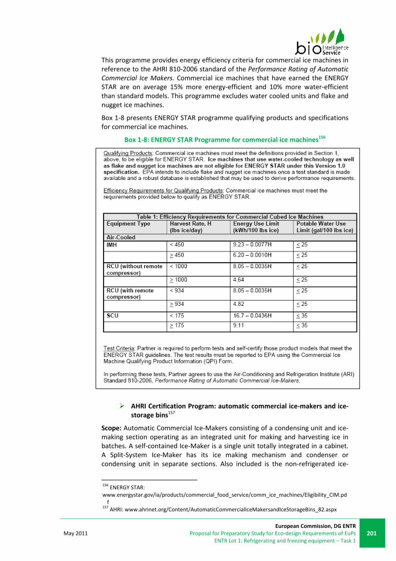
May 2011
European Commission, DG ENTR
Proposal for Preparatory Study for Eco-design Requirements of EuPs
ENTR Lot 1: Refrigerating and freezing equipment – Task 1
201
This programme provides energy efficiency criteria for commercial ice machines in
reference to the AHRI 810-2006 standard of the Performance Rating of Automatic
Commercial Ice Makers. Commercial ice machines that have earned the ENERGY
STAR are on average 15% more energy-efficient and 10% more water-efficient
than standard models. This programme excludes water cooled units and flake and
nugget ice machines.
Box 1-8 presents ENERGY STAR programme qualifying products and specifications
for commercial ice machines.
Box 1-8: ENERGY STAR Programme for commercial ice machines156
� AHRI Certification Program: automatic commercial ice-makers and ice-
storage bins157
Scope: Automatic Commercial Ice-Makers consisting of a condensing unit and ice-
making section operating as an integrated unit for making and harvesting ice in
batches. A self-contained Ice-Maker is a single unit totally integrated in a cabinet.
A Split-System Ice-Maker has its ice making mechanism and condenser or
condensing unit in separate sections. Also included is the non-refrigerated ice-
156
ENERGY STAR:
www.energystar.gov/ia/products/commercial_food_service/comm_ice_machines/Eligibility_CIM.pd
f 157
AHRI: www.ahrinet.org/Content/AutomaticCommercialIceMakersandIceStorageBins_82.aspx

202
European Commission, DG ENTR
Preparatory Study for Eco-design Requirements of EuPs
ENTR Lot 1: Refrigerating and freezing equipment – Task 1
May 2011
storage bin (non-refrigerated compartment, factory-made assembly for the
storage of ice).
Reference standards: AHRI 810-2007 on the Performance Rating of Automatic
Commercial Ice Makers and AHRI 820-2000 for Ice Storage Bins
Certified Ratings: The following Certification Program ratings are verified by test at
the Standard Rating Conditions:
• Ice Harvest Rate, lb/24 h [kg/24 h]
• Potable Water Use Rate, gal/100 lb of ice [L/45.0 kg of ice]
• Condenser Water Use Rate, gal/100 lb of ice [L/45.0 kg of ice]
• Energy Consumption Rate, kWh/100 lb of ice [kWh/45.0 kg of ice]
• Bin Theoretical Storage Capacity, lb [kg] (Self-Contained Models only)
• Theoretical Storage Capacity, lb [kg]
Ice-makers are excluded from the scope of the present study.

May 2011
European Commission, DG ENTR
Proposal for Preparatory Study for Eco-design Requirements of EuPs
ENTR Lot 1: Refrigerating and freezing equipment – Task 1
203
This page is left intentionally blank

204
European Commission, DG ENTR
Preparatory Study for Eco-design Requirements of EuPs
ENTR Lot 1: Refrigerating and freezing equipment – Task 1
May 2011
Annex 1-8: Other information
Market Transformation Programme
The Market Transformation Programme (MTP) was launched following a
consultation paper issued by the Environment & Business Division, in October
1997.
The MTP supports the development and implementation of UK Government policy
on sustainable products. MTP’s aim is to reduce the environmental impact of
products across the product life cycle by:
• Collecting information.
• Building evidence of future environmental impacts.
• Working with industry and other stakeholders.
The approach is to communicate and interpret Government policy objectives as a
set of specific action plans, or road maps, looking ahead at least ten years, and to
get buy-in from policy-makers and industry at UK, EU, and international levels.
SPMP also supports policy delivery, in particular, by developing corresponding
product ecodesign information (labels) and performance requirements (standards)
to encourage innovation and competition.
Scope: Domestic or commercial appliances including commercial refrigeration
(liquid chillers, service cabinets, cold rooms, cellar cooling equipment, ice-making
machines, refrigerated display cases, and refrigerated vending machines).
Identification of saving potentials for commercial refrigeration
In a 2006 report158, MTP develops three standard scenarios to illustrate the
potential impacts of the associate market transformation strategies:
• Reference scenario: without policy intervention
• Earliest Best Practice scenario: what would happen if everyone started
buying the best available products
• Policy scenario: estimate of the likely effects of a program of policy
measures
Comparing these scenarios, savings potential for energy use of commercial
refrigeration has been identified. The development of minimum energy
performance standards covering full and part load could help to access a
significant proportion of the identified savings potential.
There is also great potential for savings through better service/maintenance and
optimisation of present equipment and systems.
Moreover, refrigerants have an additional impact due to their direct carbon
emissions through leakages and disposal. The development of refrigerants with no
158
Sustainable Products 2006: Policy Analysis and Projections
www.mtprog.com/ReferenceLibrary/MTP_SP06_web.pdf

May 2011
European Commission, DG ENTR
Proposal for Preparatory Study for Eco-design Requirements of EuPs
ENTR Lot 1: Refrigerating and freezing equipment – Task 1
205
ozone-depleting potential and little, or no, global warming potential offers the
possibility of reducing direct carbon emissions. In the case of more efficient
refrigerants, it will reduce energy consumption and hence indirect carbon
emissions as well.
Proposed actions: The proposed actions for commercial refrigeration are:
• Revise performance criteria and expand the product range for the
Enhanced Capital Allowance (ECA) scheme to include display and service
cabinets and reverse cycle liquid chillers (>100 kW). (Revision completed in
2008)
• Engage trade groups and key buyers in green procurement initiatives.
• Develop standard and performance benchmarks for part-load operation of
liquid chillers. Part-load testing and seasonal efficiency ratings would be
more representative of the real-life situation. They need to be considered
as a potential criterion for ECA.
• Development of criteria/thresholds and implementation of the Ecodesign
Directive for display cabinets, liquid chillers and vending machines.
The figure below shows UK scenarios for service cabinet electricity consumption of
new service cabinets sold or to be sold in the UK between 2000 and 2020159
where:
• The reference projection takes into account underlying trends in markets
and technologies and the estimated or implicit impacts of historical and
current policy measures. It does not take into account the impact of
policies which are still being developed and are not targeted at specific
products. The intention is to revise these projections once it becomes
clearer how these new policy measures will affect commercial
refrigeration products.
• The Earliest Best Practice (EBP) projection shows what would happen if all
new UK sales were based on the most resource efficient options, taking
into account design and production cycles, but not taking account of price
or other market barriers.
• The P1 projection sets a target level of ambition that the Government is
proposing could be delivered at a low cost, taking into account such things
as current UK and global performance benchmarks, economies of scale
and the capacity of the supply chain to take coherent action to deliver
more energy efficient products.
159
DEFRA: Policy Brief: Improving the energy performance of commercial refrigeration products –
July 2008

206
European Commission, DG ENTR
Preparatory Study for Eco-design Requirements of EuPs
ENTR Lot 1: Refrigerating and freezing equipment – Task 1
May 2011
Figure 1-36: Indicative energy efficiency (EEI) for refrigerated service cabinets160
160
DEFRA: Policy Brief: Improving the energy performance of commercial refrigeration products –
July 2008
May 2011
European Commission, DG ENTR
Proposal for Preparatory Study for Eco-design Requirements of EuPs
ENTR Lot 1: Refrigerating and freezing equipment – Task 1
207
This page is left intentionally blank

208
European Commission, DG ENTR
Preparatory Study for Eco-design Requirements of EuPs
ENTR Lot 1: Refrigerating and freezing equipment – Task 1
May 2011
Glossary
AEC Annual energy consumption
Air-off temperature Temperature of the air blown off the evaporator (evaporating
temperature)
Air-on temperature Temperature of ambient air blown onto the condenser
Base Case An abstract construct representing the average product on the
market
BAT Best available technology
BAU Business as usual
BC Blast cabinet
Binary ice Binary ice is the mixture of a substance in solid state in micron size
and the same substance in liquid state. In some cases, it requires of a
depressant to avoid coagulation of the solid part. Normally the
employed substance is water
Blowing agent In foam production, blowing or foaming agents are chemicals that by
changing of state during the foam production process, release gases
able to change the configuration of resins (foam solid structure)
BNAT Best not-yet-available technology
CH Process chiller
Combined model Refrigeration equipments able to work in chilling and freezing cycles.
Commercial chilling
service cabinets
Refrigerated enclosure designed for the storage, but not the display,
of chilled foodstuff, accessible via one or more doors and/or
drawers, and which is able to store the foodstuff at a temperature
down to a minimum of 0°C.
Commercial freezing
service cabinets
Refrigerated enclosure designed for the storage, but not the display,
of frozen foodstuff, accessible via one or more doors and/or
drawers, that includes a compressor, condenser and evaporator, and
which is able to store the foodstuff at a temperature below 0°C.
Commercial or
industrial air-, water-
cooled refrigeration
process chillers – low
temperature
Systems including at least compressor, condenser, expansion valve
and evaporator, among other parts, designed to provide cooling
capacity for a process or chambers. They are designed to provide
outlet evaporator temperatures from -25°C to -8°C.
May 2011
European Commission, DG ENTR
Proposal for Preparatory Study for Eco-design Requirements of EuPs
ENTR Lot 1: Refrigerating and freezing equipment – Task 1
209
Commercial or
industrial air-, water-
cooled refrigeration
process chillers –
medium temperature
Systems including at least compressor, condenser, expansion valve
and evaporator, among other parts, designed to provide cooling
capacity for a process or chambers. They are designed to provide
outlet evaporator temperatures from -12°C to +3°C.
Commercial or
industrial remote air-
cooled chilling
condensing units
Combination of one or more compressor, condensers or liquid
receivers (when applicable) and the regularly furnished accessories,
specifically designed to provide cooling to other equipment at -10°C
evaporating temperature.
Commercial or
industrial remote air-
cooled freezing
condensing units
Combination of one or more compressor, condensers or liquid
receivers (when applicable) and the regularly furnished accessories,
specifically designed to provide cooling to other equipment at -32°C
evaporating temperature
COP Coefficient of performance
Critical Point The temperature and pressure at which the liquid and gaseous
phases of a pure stable substance become identical. Also called
critical state
DEC Direct energy consumption - the energy consumed directly by the
components contained with a product
Dew point temperature Temperature at which moisture condenses.
Door type Solid door / transparent door
Duty cycle The proportion of time (in %) during which a component is on and
drawing power (or the times a unit is switched under the operation
of a thermostat)
EEI Energy efficiency index
ESEER European Seasonal Energy Efficiency Ratio
Freezing Cooling or maintenance of a space and the product contained
therein to temperatures below 0°C
Functional unit The basis for comparison between similar products when performing
lifecycle analysis (e.g. one unit of storage maintained at a specific
temperature)
Gastronorm (size) It is the standard size for the tray/shelf of refrigeration equipments.
It can be reference for trolleys or shelves.
GWP Global Warming Potential
HT High temperature
210
European Commission, DG ENTR
Preparatory Study for Eco-design Requirements of EuPs
ENTR Lot 1: Refrigerating and freezing equipment – Task 1
May 2011
Integral A product that integrates the condesing unit within the body of the
equipment
Isentropric Ideal process with no change of entrophy of the system
Isentropic efficiency ratio of the product of the actual mass flow and the change in
isentropic enthalpy across the compressor to the power input
Lambda (λ) Thermal conductivity factor (λ = W/m.K)
LLCC Least lifecycle cost
Load The demand (in %) on a compressor's cooling capacity
Load-line For each part of the cabinet, boundary surface consisting of one or
several planes within which all test packages may be stored within
the temperature limits of the actual temperature class
LT Low temperature
MEPS Minimum energy performance standards
MT Medium temperature
Net volume Adjusted internal volume, used to reflect space which can in practice
be used to store goods
ODP Ozone Depleting Potential
OEM Original equipment manufacturer
Operation temperature Temp of storage space (target temperature/operating
temperature/application temperature)
Packaged A product that has been manufactured and provided as a single piece
of equipment
Pass through Equipments similar to roll-in, but presenting two doors, one for the
loading and the other one for the unloading.
Performance parameter The means of comparing performance of similar products, using the
functional unit and product consumption/impact (e.g. annual
electricity consumption of product divided by number of functional
units it provides)
Plug-in A product that operates after being plugged into the mains (i.e. no
professional installation required)
Plug-in commercial blast
chilling cabinet
Equipment that includes compressor, condensor, evaporator and at
least one fan able to cool down the temperature of the foodstuff
from +70°C to +3°C in a short period of time, i.e. 90 minutes. The
foodstuff is arranged in trays within the equipment or trolleys that

May 2011
European Commission, DG ENTR
Proposal for Preparatory Study for Eco-design Requirements of EuPs
ENTR Lot 1: Refrigerating and freezing equipment – Task 1
211
are taken into the equipment.
Plug-in commercial blast
chilling/freezing cabinet
Equipment that includes compressor, condensor, evaporator and at
least one fan able to chill or freeze the foodstuff from 70°C to +3°C
and -18°C respectively in 90 or 240 minutes. The foodstuff is
arranged in trays within the equipment or trolleys that are taken into
the equipment.
Plug-in commercial blast
freezing cabinet
Equipment that includes compressor, condensor, evaporator and at
least one fan able to freeze the temperature of the foodstuff from
70°C to -18°C in a short period of time, 240 minutes. The foodstuff is
arranged in trays within the equipment or trolleys that are taken into
the equipment.
Protocol Specific door opening pattern used during testing to evaluate a
product’s performance under a standard
R value Thermal resistance value (R = m2.K/W)
Reach-in / cabinet Refrigeration equipments where the user stands outside the
appliance to load and unload the foodstuff.
REC Refrigeration energy consumption - the energy consumed by the
refrigeration system
Refrigeration Cooling or maintenance of a space and the product contained
therein to temperatures above 0°C
Remote A product with a remote condensing unit
RCU Remote condensing unit
Remote commercial
blast chilling cabinet
Equipment that includes compressor, evaporator and at least one
fan. It is connected to a remote condensing unit. This equipment is
able to cool down the temperature of the foodstuff from +70°C to
+3°C in a short period of time, i.e. 90 minutes. The foodstuff is
arranged in trays within the equipment or trolleys that are taken into
the equipment.
Remote commercial
blast chilling/freezing
cabinet
Equipment that includes compressor, evaporator and at least one
fan. It is connected to a remote condensing unit. This equipment is
able to chill or freeze the foodstuff from 70°C to +3°C and -18°C
respectively in 90 or 240 minutes. The foodstuff is arranged in trays
within the equipment or trolleys that are taken into the equipment.
Remote commercial
blast freezing cabinet
Equipment that includes compressor, evaporator and at least one
fan. It is connected to a remote condensing unit. This equipment is
able to freeze the temperature of the foodstuff from 70°C to -18°C in
a short period of time, 240 minutes. The foodstuff is arranged in
trays within the equipment or trolleys that are taken into the
equipment.

212
European Commission, DG ENTR
Preparatory Study for Eco-design Requirements of EuPs
ENTR Lot 1: Refrigerating and freezing equipment – Task 1
May 2011
Roll-in / trolley Refrigerating equipments of foodstuff where trolleys are wheeled-
in. The load and discharge is done using the door.
SC Service cabinet
Split system A refrigeration system that has been split - the evaporator is
separate from the refrigeration system (terminology normally used
for air-conditioning)
Subcritical refrigeration The refrigeration cycles are entirely below the critical pressure point
of the refrigerant
Superheating Superheating is referred to the process of heating a substance over
its boiling point. This is reached under specific pressure conditions.
TEC Total energy consumption; TEC = REC (refrigeration energy
consumption) + DEC (direct energy consumption) for remote
refrigeration systems; TEC = DEC for plug-in refrigeration systems
Testing m-package Measurement packaged used in testing to replicate food, usually
includes thermometer to measure temperature.
TEWI Total equivalent warming impact
Transcritical Parts of the refrigeration cycle are above and other parts are below
the critical pressure point of the refrigerant.
Trigeneration CCHP (combined cooling, heating, and power generation)
Triple point State where co-existence of liquid-, vapour- and solid-phase is
possible. This phenomenon depends on the pressure and
temperature
U value Thermal conductance factor (U = W/m2.K)
US DOE United States Department of Energy
Use pattern The time a unit is switched 'on', providing cooling
VEPS Voluntary efficiency performance standards
Vertical unit Machine with a vertical design or layout.
WICR Walk-in cold room
Water-off Temperature of water leaving a chiller