tangible, dynamic holographic images - mit media lab
TRANSCRIPT

In Three-Dimensional Holographic Imaging, Eds. C.J. Kuo and M.H. Tsai, Wiley-Interscience, 2001 1
Tangible, Dynamic Holographic ImagesWENDY PLESNIAK, RAVIKANTH PAPPU, AND STEPHEN BENTON
Media Laboratory, Massachusetts Institute of TechnologyCambridge, Massachusetts 02139
Good holograms are bewitching. They command our eyes to their images, to search the marvelous realness of sur-faces, textures, and minute detail for some aberration, some visual clue that will dissuade us from seeing as real what we know is not. Yet while they seem to assemble the very molecules of physical matter for us to ponder, they also present a conundrum: The objects they render appear frozen, lifeless, and confounding to our fingertips.
What if we could render these images animate and touchable, as phantom material that was both dynamic and plastic? Such an ultimate display would be both powerful and magical; it would deliver naturally to our spatial proficiencies, inspire our imaginations, and perhaps even provoke our emotions. Of course, such a display does not yet exist, and many challenges to its development remain. But while current technology still leaves us in the shadow of such a goal, we are beginning to see it as more real than chimerical.
To this end, we will describe our first experiments with tangible, dynamic holographic images. Our prototype system, called the holo-haptic system, comprises a sizeable arsenal of computers and both commercial and custom hardware. The visual images it produces for these experiments are monochromatic, postcard-sized, and depict only simple geometries. The haptic images it produces are felt and shaped with a hand-held device. Thus, the trappings of engi-neering are anything but transparent to the experience, and the demonstrations themselves are artistically unsophisti-cated. But by using this agglomeration of technology in simple demonstrations, we can feel and sculpt three-dimensional shapes made only of light — which inches us closer to where we want to go.
5.1 INTRODUCTION
People perceive, think and act quite naturally in a spatial theater. At a glance, we understand the layout of our envi-ronment, the locations and shapes of objects within reach. We apprehend and manipulate these objects without a thought, skillfully, and sometimes even artfully. Yet, even while great attention is turned toward human-centered engineering and interaction design in computer-based applications, the full exploratory and manipulative dexterity of the hand and the sensorimotor advantages of binocular vision are not commonly pressed into service. The reasons for this are two-fold: The point-and-click desktop paradigm still dominates our notion about how to interact with com-puters; and it remains challenging to design and build the new sensing and display technologies that will enable a new way of working.
Obviously, it is not always desirable to take input from mouse-twiddled GUI buttons, sliders, and the keyboard, or to always deposit output into a flat display window, though these are the archetypal input-output (I/O) channels. Even using virtual reality (VR)-style head-mounted displays combined with body tracking seems now a cumbersome and tired approach. Yet new technologies and methods of using them continue to emerge, and with them comes the prom-ise of new and imaginative tools that cater to our natural, spatial strategies for doing things. Among these technolo-gies are displays and sensors that are minimally or not at all body borne and that allow us to use two eyes and hands within manipulatory, interactive, or reactive workspaces.
The attending interaction design possibilities might better serve human perception and performance: For instance, two-handed input is known to provide some manual and cognitive benefits [1]; and including binocular vision and motion parallax helps a viewer to better understand shape and layout and to plan and execute prehensile movement in the workspace [2,3]. The coaction of eye and hand in manipulatory space might even be reinforced by spatially colo-cating the manual work volume with the visual one or by merging the controller and display entirely.
Diminishing the evidence of technology situated between our action and a computer-based system’s response also shrinks our psychological awareness of the symbolic interpretation, instruction, and actuation that occurs there. In the

In Three-Dimensional Holographic Imaging, Eds. C.J. Kuo and M.H. Tsai, Wiley-Interscience, 2001 2
real world, whether we are hammering a nail or squeezing a block of clay, most actions we exert on objects seems so directly and inextricably linked to the their reactions that we do not normally distinguish between what is input and output. Mixing this kind of “Newtonian” interaction with the freedom to express system response as anything from physically based to purely poetic offers us rich new territory for engineering and interaction design.
It is within this context that we situate our recent work with electro-holography and force feedback. The specific project we describe here provides a physically based, though highly stylized, emulation of a task that has a real-life analogue — the lathing of rotating stock. We display a free-standing holographic image combined with a force image that can be directly felt and carved with a hand-held tool. The visual and force images are spatially colocated, engag-ing eye and hand together and attempting to veil the computation nested between input and display. Many other research efforts, employing a wide range of technologies, have contributed a diverse set of applications related by these elements of interaction and workspace design. Some depart from strictly physically based simulation and exploit the malleability of the computational rules translating action into response; others, like ours, simply try to simulate a task already practiced in the physical world. The following section provides a brief overview of some of these projects, which have either inspired or enabled our holo-haptic work.
5.2 CONTEXT
One project that is thematically related to our work is the “Virtual Lathe” described and presented at SIGGRAPH’92 by Deering [4]. In this demonstration, a head-tracked stereo display showed a computer-graphic stock, spinning about its long axis, which a person could interactively carve using a rod-shaped three-dimensional 3D mouse. The demon-stration underscored popular interest in having a more direct way to interact with virtual prototyping systems. But without force feedback, the Virtual Lathe provided neither the important sense of contact with the simulated stock, nor the feel of carving.
A wide variety of virtual reality (VR) and augmented reality (AR) application areas such as telesurgery, entertain-ment, and maintenance analysis and repair do employ computational haptics and stereo computer graphics to feel, see, and interact with data. Most existing demonstrations offset the visual and manual workspaces, so that a person manipulates her hand in one place while visually monitoring its action and the system’s response on another separate display. Fewer attempts to conjoin eyes and hands in a coincident workspace have been reported. Two compelling examples are Boston Dynamics’s virtual reality surgical simulator [5], and the nano Workbench at the University of North Carolina (UNC) at Chapel Hill [3]. Both of these systems use force feedback and head-tracked stereo visual display with LCD shutter goggles, and they let the hand-held device appear to operate directly on the visually-dis-played data.
Another interesting system which incorporates computational haptics (but no stereo viewing), called the WYSIWYF (What You See Is What You Feel) display [7], has been demonstrated at Carnegie Mellon University. Here the visual display behaves like a moveable “magic window”, interposed between the viewer’s eyes and hand, and through which the hand can be seen interacting with a virtual, tangible scene. The system uses a haptic manipulator and image compositing to present the computer graphically rendered scene overlayed by a video image of the operator’s hand/arm and the accompanying force model. Without properly representing occlusion, however, WYSIWYF is unable to always display the correct visual relationship between hand and scene, and it also provides only monocular cues to depth.
Rather than using computational haptic feedback, actual “wired” physical controllers can be employed. These inter-face objects act as physical handles for virtual processes, may have on-board sensing, computation and intercommu-nication, and can be hand manipulated and spatially commingled with visual output. A person using them can enjoy the simplicity of interacting with physical objects, while observing the outcome displayed on or near the controller, in a separate location, or in the ambient environment. Several of these efforts have been presented recently: for instance, EuroPARC’s Digital Desk [8], MIT Media Lab’s metaDESK [9], and IlluminatingLight [10]. Yet, while providing whole-hand interaction and richly programmable visual feedback, using physical controllers restricts the bulk and tactual feel as well as the physical behaviors of the input devices to be bound by physical mechanics.

In Three-Dimensional Holographic Imaging, Eds. C.J. Kuo and M.H. Tsai, Wiley-Interscience, 2001 3
Conversely, a system that has programmable haptic display but restricted visual output is Dimensional Media’s High Definition Volumetric Display. This system incorporates force feedback and a reimaging display, which employs optical components to relay and composite images of already-existing 3D objects and/or 2D display screens. As a result, using a force feedback device to interact with the optical output (which can appear strikingly realistic) to mod-ify the geometry of the displayed object is not possible.
Holography is another optical display technique that can project spatial images into a viewer’s manual workspace. The combination of haptics and holography was first investigated by researchers at De Montfort Univer-sity in an object inspection task [11]. In this work, visual display was provided by a reflection transfer hologram that presented an aerial image of a control valve, while a computer controlled tactile glove provided coincident haptic dis-play of the same data. Subsequent informal experiments in combining reflection transfer holograms with force feed-back were also performed at the MIT Media Laboratory’s Spatial Imaging Group. Since reflection holograms require front overhead illumination for image reconstruction, the interacting hand could literally block the holographic image in both of these holo-haptic efforts.
This problem was addressed by employing full-parallax edge-illuminated holograms in combination with a force-feedback device for the inspection of 3D models [12]. The edge-illuminated hologram format allowed hand move-ments in the visual workspace in front of the hologram plane without blocking illumination (Fig. 5.1). Thus, a viewer could haptically explore the spatially registered force model while visually inspecting the holographic image details over a wide field of view. The DeMontfort and MIT holo-haptic displays were static, however; no dynamic modifica-tion could be made to the displayed image.
Figure 5.1 Edge-illuminated haptic holograms.
5.3 HAPTICS AND HOLOGRAPHIC VIDEO
Haptics is a general term referring to elements of manual interaction with an environment. This interacting may be done by either human hands or sensing machines in an environment which may be physical or simulated. In our case, the interactions are accomplished by human hands that sense force information as they explore and manipulate. By bringing together computational haptics and electro-holography, we hoped to render simple scenes that could be seen, felt, and modified in the manual workspace. Of course, there is little value in demonstrating a multimodal simulation with a stable haptic simulation, but a visual frame rate of only one frame every few seconds; electro-holography cur-rently suffers from limited computation and communication bandwidth, leading to just this problem. In order to
In Three-Dimensional Holographic Imaging, Eds. C.J. Kuo and M.H. Tsai, Wiley-Interscience, 2001 4
increase our visual update rate, we chose to take two simplifying measures: First, rather than being entirely recom-puted, the hologram itself would be updated only in regions of change; second, the underlying object geometry would only be modified by interaction in a constrained way.
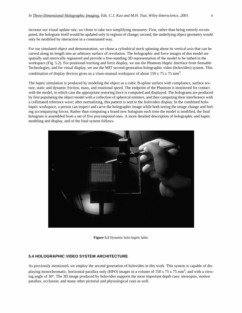
For our simulated object and demonstration, we chose a cylindrical stock spinning about its vertical axis that can be carved along its length into an arbitrary surface of revolution. The holographic and force images of this model are spatially and metrically registered and provide a free-standing 3D representation of the model to be lathed in the workspace (Fig. 5.2). For positional tracking and force display, we use the Phantom Haptic Interface from Sensable Technologies, and for visual display, we use the MIT second-generation holographic video (holovideo) system. This combination of display devices gives us a visuo-manual workspace of about 150 x 75 x 75 mm3.
The haptic simulation is produced by modeling the object as a cubic B-spline surface with compliance, surface tex-ture, static and dynamic friction, mass, and rotational speed. The endpoint of the Phantom is monitored for contact with the model, in which case the appropriate restoring force is computed and displayed. The holograms are produced by first populating the object model with a collection of spherical emitters, and then computing their interference with a collimated reference wave; after normalizing, this pattern is sent to the holovideo display. In the combined holo-haptic workspace, a person can inspect and carve the holographic image while both seeing the image change and feel-ing accompanying forces. Rather than computing a brand new hologram each time the model is modified, the final hologram is assembled from a set of five precomputed ones. A more detailed description of holographic and haptic modeling and display, and of the final system follows.
Figure 5.2 Dynamic holo-haptic lathe.
5.4 HOLOGRAPHIC VIDEO SYSTEM ARCHITECTURE
As previously mentioned, we employ the second generation of holovideo in this work. This system is capable of dis-playing monochromatic, horizontal-parallax-only (HPO) images in a volume of 150 x 75 x 75 mm3, and with a view-ing angle of 30°. The 3D image produced by holovideo supports the most important depth cues: stereopsis, motion parallax, occlusion, and many other pictorial and physiological cues as well.

In Three-Dimensional Holographic Imaging, Eds. C.J. Kuo and M.H. Tsai, Wiley-Interscience, 2001 5
Generally speaking, the second-generation system accepts two inputs: a computer-generated hologram (CGH) and light. Its output is a free-standing, 3D holographic image whose visual and geometrical characteristics depend on how the CGH was computed. Each CGH contains 36 megasamples, at one byte per sample, apportioned into 144 lines of 256 kilosamples each. The methods of computing these holograms, delivering them to the display, and producing an image are described in the following sections.
5.4.1 Optical Pipeline
The design strategy [13] for the second-generation holovideo display was to exploit parallelism wherever possible, both optically and electronically, such that the approach would be extensible to arbitrarily large image-sized displays. To produce an image volume of 150 x 75 x 75 mm3, two 18-channel acousto-optic modulators (AOMs) were used, with AOM channels modulating beams of Helium-Neon laser light in parallel. Six tiled horizontal mirrors scan across the output, matched to the speed of the signal in the AOM, such that the relayed image of the diffraction pattern in the AOM is stationary. As the mirrors scan from left to right, one AOM provides 18 lines of rastered image. When the mirrors return from right to left, the second crossfired AOM provides the next 18 lines of rastered image. A vertical scanner images each 18-line pass below the previous one, with 8 horizontal scans in all, providing 18x8=144 vertical scan lines in the final image.
This resulting image is HPO, with video resolution in the vertical direction, and holographic resolution in the hori-zontal direction. To match the shear-mode active bandwidth of the tellurium dioxide AOM crystal, we need to pro-duce a signal with a bandwidth of approximately 50 MHz. So that the output sampling satisfies the Nyquist criterion, we use a pixel clock of 110 Mhz. As mentioned earlier, each horizontal line of the display is 256 Kbytes of holo-graphic fringe pattern; 144 of these hololines make up the final hologram, yielding 36 Mbytes of information per frame. Since the display has no persistence, it must be refreshed at 30 Hz, thus requiring an average data rate of 1Gbyte per second from the frame buffers.
An 18-channel reconfigurable frame buffer was required to drive the display. While no known commercially avail-able frame buffer is capable of the required data rate, we were able to adapt the Cheops Imaging System [14] to the task. Cheops is a data-flow architecture digital video platform developed at the MIT Media Laboratory. The Holov-ideo Cheops system provides six synchronized frame buffers to drive our 256Kbyte x 144 display as well as a high speed interface to host processors and a local data-flow processing card for the decoding of encoded or compressed image formats. The entire optical pipeline of the second generation system is depicted in Figure 5.3.
Figure 5.3 Optical pipeline.
In Three-Dimensional Holographic Imaging, Eds. C.J. Kuo and M.H. Tsai, Wiley-Interscience, 2001 6
5.4.2 Computational pipeline
The production of a traditional optical hologram or holographic stereogram requires an object-modulated wave and an interfering reference wave, and results in a real fringe pattern recorded in a photosensitive medium. In computa-tional holography, we start with a three-dimensional, mathematical or computer-graphic model of a scene and com-pute a holographic fringe pattern from it. In this case, the fringe pattern is simply an array of numbers; but when written to a spatial light modulator, it can diffract input light in a directed fashion to produce a spatial image of the original model. We will describe two distinct ways of generating a CGH from the same object model, the interference modeling and the stereogram modeling approach. Both methods were tested to generate holographic images for the holo-haptic lathe. In both cases, the initial object model and the final display pipeline are identical but the intervening algorithmic subsystems are distinct.
5.4.2.1 Interference Modeling Approach A “fully-computed hologram” is a fringe pattern resulting from the computational modeling of the interference process. In the ideal case, the wavefront reconstructed by the display would be perceptually indistinguishable from one scattered by the original object. In practice, however, there are sig-nificant departures from this ideal. These departures are a consequence of modeling and shortcuts taken to make the computation and display of fringe patterns tractable, and also due to many technological limitations.
As such, computation of the fringe pattern proceeds through three stages: scene modeling, occlusion processing, and interference modeling. The scene modeling subsystem uses standard computer-graphics techniques to generate an intermediate wireframe or shaded polygonal description of the scene. To represent the object as a collection of point sources, we populate each polygon with a series of self-luminous points and assign a location, amplitude and initial phase to each of them. This particular representation for the object field was chosen because point sources have a par-ticularly simple mathematical form, and interference patterns arising from them are fairly simple to compute. Arti-facts of spatially and temporally coherent illumination are diminished by randomly varying the inter-point spacing, which is on the order of ten points/mm, or by assigning uniformly distributed random initial phases. Each point is then assigned to one of the 144 hololines, according to its vertical projection onto the hologram plane. Since we are computing HPO holograms, each object point will contribute only to its assigned hololine.
The sorted points are then passed to an occlusion processing system, described in more detail elsewhere [15], which computes for each point radiator the set of regions on the hololine to which it contributes. With this information, the fringe pattern can be rendered. Since there may be hundreds or hundreds of thousands of points in a scene, computa-tion time in all stages of hologram generation (from modeling through fringe rendering) is highly dependent on object complexity.
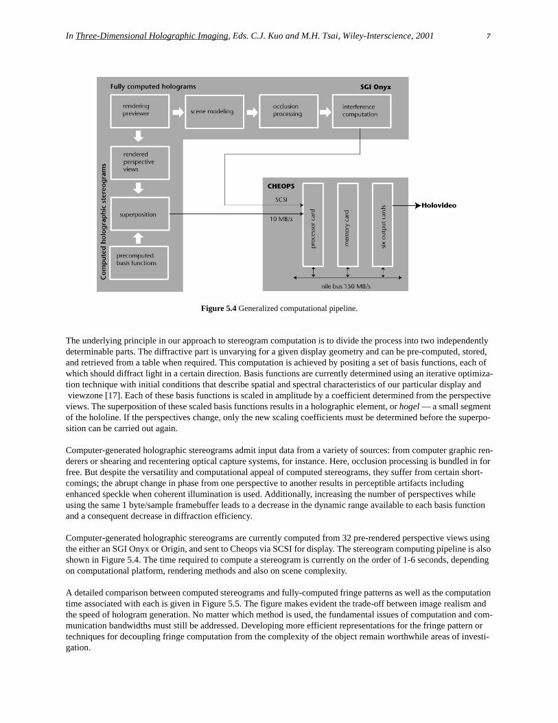
Fringe rendering is accomplished by approximating the classical interference equation for each sample on the holo-line. The contribution from each subscribing point radiator is totaled, and the intensity at the current sample is deter-mined. The final result is normalized and quantized to the range 0-255 to represent each sample as a 1-byte quantity. This hologram computation is currently implemented on an SGI Onyx workstation. The final hologram, which takes on the order of ten minutes to compute (depending on object complexity), is then dispatched to Cheops via a SCSI link at about 10 Mbits per second; the final image is then viewable on the display. The entire computational pipeline, from modeling to display, is shown in Figure 5.4.
5.4.2.2 Stereogram modeling approach Whereas fully-computed holograms offer continuous parallax through the viewzone, a holographic stereogram uses wavefront reconstruction to present a finite number of perspective views of a scene to an observer. A stereogram’s discretization of parallax views results in a discrete approximation to the ideal reconstructed wavefront [16], and this approximation permits a considerable increase in computational speed.
In Three-Dimensional Holographic Imaging, Eds. C.J. Kuo and M.H. Tsai, Wiley-Interscience, 2001 7
Figure 5.4 Generalized computational pipeline.
The underlying principle in our approach to stereogram computation is to divide the process into two independently determinable parts. The diffractive part is unvarying for a given display geometry and can be pre-computed, stored, and retrieved from a table when required. This computation is achieved by positing a set of basis functions, each of which should diffract light in a certain direction. Basis functions are currently determined using an iterative optimiza-tion technique with initial conditions that describe spatial and spectral characteristics of our particular display and viewzone [17]. Each of these basis functions is scaled in amplitude by a coefficient determined from the perspective views. The superposition of these scaled basis functions results in a holographic element, or hogel — a small segment of the hololine. If the perspectives change, only the new scaling coefficients must be determined before the superpo-sition can be carried out again.
Computer-generated holographic stereograms admit input data from a variety of sources: from computer graphic ren-derers or shearing and recentering optical capture systems, for instance. Here, occlusion processing is bundled in for free. But despite the versatility and computational appeal of computed stereograms, they suffer from certain short-comings; the abrupt change in phase from one perspective to another results in perceptible artifacts including enhanced speckle when coherent illumination is used. Additionally, increasing the number of perspectives while using the same 1 byte/sample framebuffer leads to a decrease in the dynamic range available to each basis function and a consequent decrease in diffraction efficiency.
Computer-generated holographic stereograms are currently computed from 32 pre-rendered perspective views using the either an SGI Onyx or Origin, and sent to Cheops via SCSI for display. The stereogram computing pipeline is also shown in Figure 5.4. The time required to compute a stereogram is currently on the order of 1-6 seconds, depending on computational platform, rendering methods and also on scene complexity.
A detailed comparison between computed stereograms and fully-computed fringe patterns as well as the computation time associated with each is given in Figure 5.5. The figure makes evident the trade-off between image realism and the speed of hologram generation. No matter which method is used, the fundamental issues of computation and com-munication bandwidths must still be addressed. Developing more efficient representations for the fringe pattern or techniques for decoupling fringe computation from the complexity of the object remain worthwhile areas of investi-gation.

In Three-Dimensional Holographic Imaging, Eds. C.J. Kuo and M.H. Tsai, Wiley-Interscience, 2001 8
Figure 5.5 Comparing fully-computed holograms and computed holographic stereograms.
5.5 HOLO-HAPTIC LATHE IMPLEMENTATION
5.5.1 System Overview
Three separate processes support our holo-haptic display: a haptics module which performs force modeling; the holovideo module which precomputes holograms and drives rapid local holographic display updates based on changes to the model; and the workspace resource manager (WRM) which links the two. More specifically, the WRM is notified by the haptics module of geometry changes imparted to the model by an interacting user. It deter-mines the regions of the hologram affected by new model changes and the closest visual approximation to the haptic change, and then makes requests to the holovideo module for the corresponding local hologram updates. The holov-ideo module assembles the updated chunk of hologram from a set of precomputed holograms and swaps them into the one currently displayed. From the point of view of a user, who is holding the stylus and pressing it into the holo-graphic image, a single multimodal representation of the simulation can be seen and felt changing in response to the applied force. The system architecture is shown in Figure 5.6.

In Three-Dimensional Holographic Imaging, Eds. C.J. Kuo and M.H. Tsai, Wiley-Interscience, 2001 9
Figure 5.6 Dynamic holo-haptic system architecture.
5.5.2 Haptic Modeling and Display
As mentioned previously, we use the Phantom haptic device, which interfaces to the body via a hand-held stylus. The stylus can be used to probe a simulated or mixed-reality scene and displays force when appropriate, back to the user. Six encoders on the device are polled to compute the stylus tip’s position, and this information is checked against the geometry of our haptic stock. If contact is detected between the stylus tip and the stock model, appropriate torque commands are delivered to the device’s three servomotors; thus a restoring force is felt by the hand holding the stylus. The device has an addressable workspace of about 290 x 400 x 560 mm3.
The haptic stock, initially and in subsequent stages of carving, is represented as a surface of revolution with two caps. It has a mass of 1 g, an algorithmically defined vertical grating (with a 1 mm pitch and 0.5 mm height) as a surface texture, static and dynamic frictional properties, and stiff spring bulk resistance. The haptic stock rotates about its vertical axis at 1 rev/s and straddles a static haptic plane (which spatially corresponds with the output plane of the holovideo optical system). The haptic plane is modeled with the same bulk and frictional properties as the stock.
The haptic stock maintains rotational symmetry about its vertical axis initially and in all subsequent stages of carving. Its radius profile is represented by a cubic B-spline curve; initially, all control points, P, are set to the same radial dis-tance (25 mm) from the vertical axis to let us begin lathing a cylinder. Control points are modified as force is exerted on the stock at height h, corresponding to a location along the curve between control points Pi and Pi+1. A new radius for the entire surface of revolution at this height is computed by evaluating the nonuniform rational B-spline formula-tion, and this change is immediately reflected in the model geometry. The stock can be felt to spin beneath the user’s touch, and when pressed with enough force (when the surface has been penetrated by some threshold distance D) its surface deforms (Fig. 5.7).
The haptic model can be carved away from its original radius (25 mm) down to a minimum radius (15 mm); the min-imum radius is enforced so that once the stock has deformed this much, the control points will update no further. The control point density was derived though trial and error, to enable fairly intricate carving without permitting deep notches which introduce instabilities into the haptic simulation.

In Three-Dimensional Holographic Imaging, Eds. C.J. Kuo and M.H. Tsai, Wiley-Interscience, 2001 10
Figure 5.7 Lathing the haptic model.
5.5.3 Pre-computed Holograms and Limited Interaction
Ideally, haptic interaction could arbitrarily modify the object model, and realistic visual feedback would be displayed in concert with carving. However, as mentioned earlier, we must take several simplifying measures to achieve near-real-time simulation. First, we limit the way the underlying object geometry can be modified by working with an object model that always maintains rotational symmetry, as described above. Second, we pre-compute a set of holo-grams and reassemble the final hologram from them; the resulting final hologram displays an approximation to the model’s shape.
The haptic model of the stock is continuous and varies smoothly along its carved profile. In our implementation, translating changes in this model to hologram updates requires going through an intermediate representation. This intermediate representation (dubbed the “stack”) treats the stock as a pile of 120 disks, each of some quantized radius nearest to the haptic stock radius at a corresponding height. We select from a set of five radii, ranging from the initial radius of the haptic stock, down to the minimum radius permitted by carving. The number of disks in the stack repre-sents the number of display lines occupied by the final holographic image, and also corresponds to the physical height of the haptic model. It is an image of the stack that is reconstructed holographically, yielding a visual image that is an approximation to the accompanying force image.
Figure 5.8 Method of propagating haptic model changes to holovideo display.
To efficiently assemble a hologram of the stack, we first pre-compute a set of five holograms of cylinders, each hav-ing a different radius determined from the set mentioned above. A hologram of the stack is assembled by using appro-priate lines from each of the pre-computed holograms at appropriate locations in the final one. For instance, if a region in the middle of the haptic stock has abruptly been shaved down to its minimum radius, only the middle lines
In Three-Dimensional Holographic Imaging, Eds. C.J. Kuo and M.H. Tsai, Wiley-Interscience, 2001 11
on the holovideo display are changed by swapping in corresponding lines from the minimum-radius hologram. The entire process is depicted in Figure 5.8.
Since we use precomputed holograms for this work and thereby relax our need for their rapid generation, we chose to use the more realistic images afforded by the fully-computed method. While holographic stereograms are faster to produce, the algorithm described earlier produces image artifacts, and the final holographic images lack the sharpness and dynamic range which enhance the appearance of solidity.
5.6 RESULTS
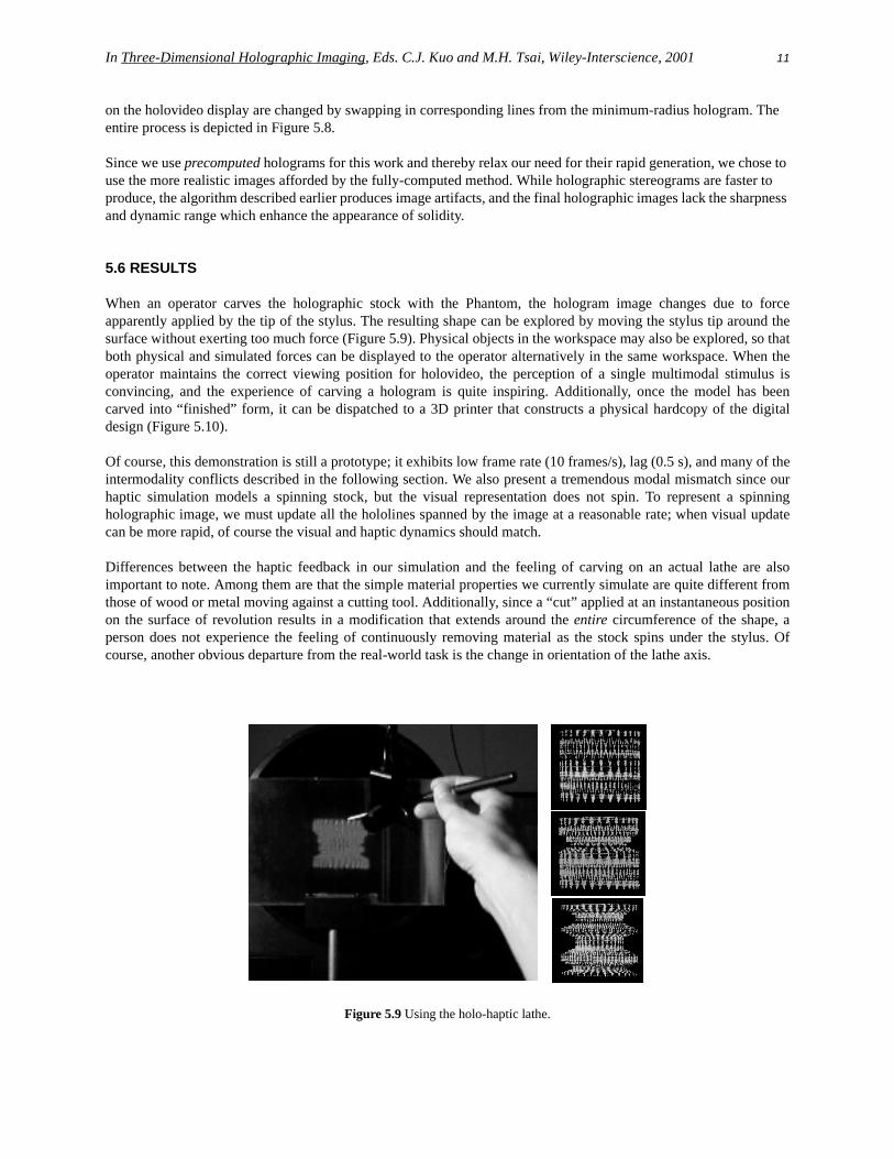
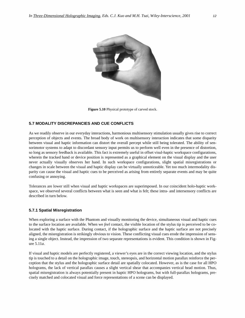
When an operator carves the holographic stock with the Phantom, the hologram image changes due to forceapparently applied by the tip of the stylus. The resulting shape can be explored by moving the stylus tip around thesurface without exerting too much force (Figure 5.9). Physical objects in the workspace may also be explored, so thatboth physical and simulated forces can be displayed to the operator alternatively in the same workspace. When theoperator maintains the correct viewing position for holovideo, the perception of a single multimodal stimulus isconvincing, and the experience of carving a hologram is quite inspiring. Additionally, once the model has beencarved into “finished” form, it can be dispatched to a 3D printer that constructs a physical hardcopy of the digitaldesign (Figure 5.10).
Of course, this demonstration is still a prototype; it exhibits low frame rate (10 frames/s), lag (0.5 s), and many of theintermodality conflicts described in the following section. We also present a tremendous modal mismatch since ourhaptic simulation models a spinning stock, but the visual representation does not spin. To represent a spinningholographic image, we must update all the hololines spanned by the image at a reasonable rate; when visual updatecan be more rapid, of course the visual and haptic dynamics should match.
Differences between the haptic feedback in our simulation and the feeling of carving on an actual lathe are alsoimportant to note. Among them are that the simple material properties we currently simulate are quite different fromthose of wood or metal moving against a cutting tool. Additionally, since a “cut” applied at an instantaneous positionon the surface of revolution results in a modification that extends around the entire circumference of the shape, aperson does not experience the feeling of continuously removing material as the stock spins under the stylus. Ofcourse, another obvious departure from the real-world task is the change in orientation of the lathe axis.
Figure 5.9 Using the holo-haptic lathe.
In Three-Dimensional Holographic Imaging, Eds. C.J. Kuo and M.H. Tsai, Wiley-Interscience, 2001 12
Figure 5.10 Physical prototype of carved stock.
5.7 MODALITY DISCREPANCIES AND CUE CONFLICTS
As we readily observe in our everyday interactions, harmonious multisensory stimulation usually gives rise to correctperception of objects and events. The broad body of work on multisensory interaction indicates that some disparitybetween visual and haptic information can distort the overall percept while still being tolerated. The ability of sen-sorimotor systems to adapt to discordant sensory input permits us to perform well even in the presence of distortion,so long as sensory feedback is available. This fact is extremely useful in offset visul-haptic workspace configurations,wherein the tracked hand or device position is represented as a graphical element on the visual display and the usernever actually visually observes her hand. In such workspace configurations, slight spatial misregistrations orchanges in scale between the visual and haptic display can be virtually unnoticeable. Yet too much intermodality dis-parity can cause the visual and haptic cues to be perceived as arising from entirely separate events and may be quiteconfusing or annoying.
Tolerances are lower still when visual and haptic workspaces are superimposed. In our coincident holo-haptic work-space, we observed several conflicts between what is seen and what is felt; these intra- and intersensory conflicts aredescribed in turn below.
5.7.1 Spatial Misregistration
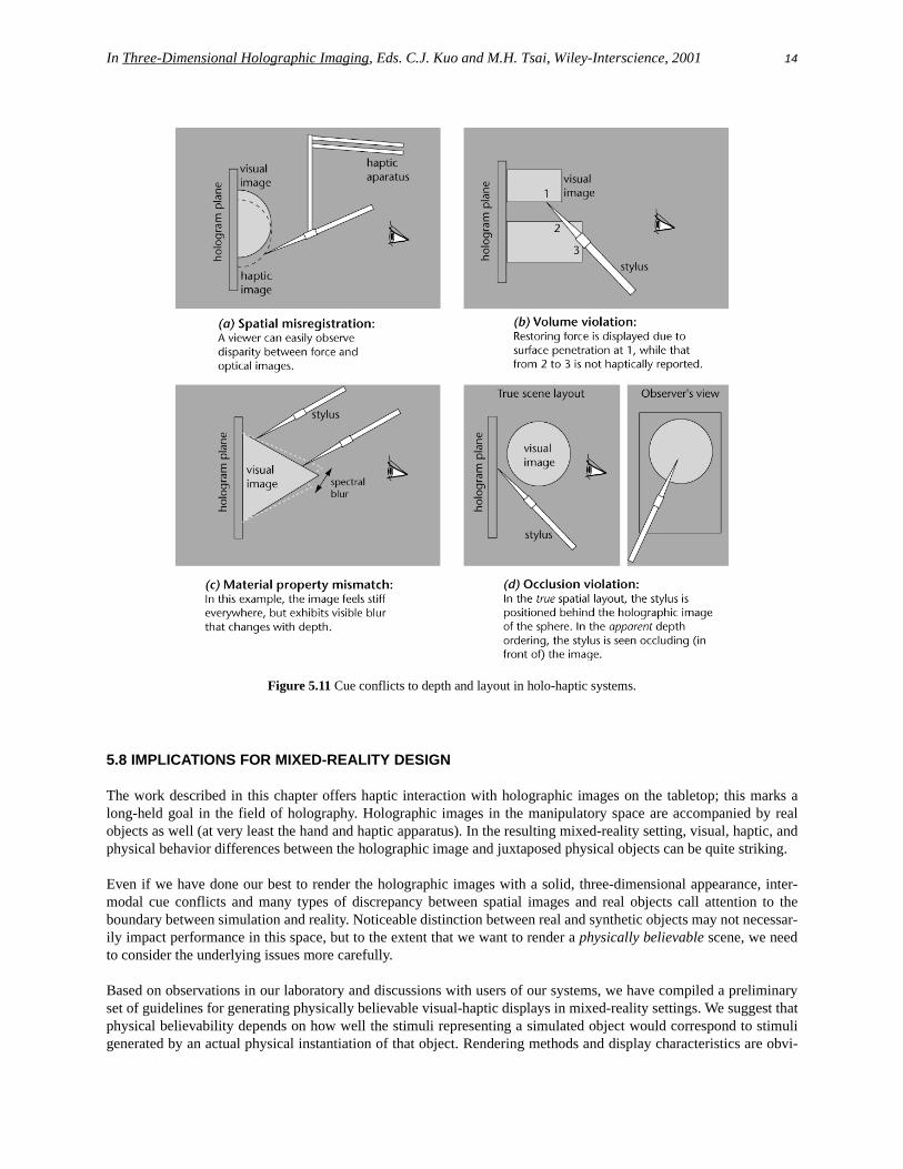
When exploring a surface with the Phantom and visually monitoring the device, simultaneous visual and haptic cuesto the surface location are available. When we feel contact, the visible location of the stylus tip is perceived to be co-located with the haptic surface. During contact, if the holographic surface and the haptic surface are not preciselyaligned, the misregistration is strikingly obvious to vision. These conflicting visual cues erode the impression of sens-ing a single object. Instead, the impression of two separate representations is evident. This condition is shown in Fig-ure 5.11a.
If visual and haptic models are perfectly registered, a viewer’s eyes are in the correct viewing location, and the stylustip is touched to a detail on the holographic image, touch, stereopsis, and horizontal motion parallax reinforce the per-ception that the stylus and the holographic surface detail are spatially colocated. However, as is the case for all HPOholograms, the lack of vertical parallax causes a slight vertical shear that accompanies vertical head motion. Thus,spatial misregistration is always potentially present in haptic HPO holograms, but with full-parallax holograms, pre-cisely matched and colocated visual and force representations of a scene can be displayed.

In Three-Dimensional Holographic Imaging, Eds. C.J. Kuo and M.H. Tsai, Wiley-Interscience, 2001 13
5.7.2 Occlusion Violations
Occlusion is perhaps the most powerful cue to layout in a scene. When we see the image of an object being blockedby the image of another, we understand the occluded object to be farther from our eye than the occluding one. In ourholo-haptic system, it is possible to position the haptic apparatus between hologram and image and actually block itsreconstruction; in an observer’s view of the scene, occlusion relationships contradict other depth cues reporting truescene layout as shown in Figure 5.11d. Even in the presence of correct depth accounting from stereopsis and motionparallax, perception appears to favor the depth ordering reported by occlusion relationships.
5.7.3 Volume Violations
Obviously, holograms present spatial images which cannot by themselves exhibit a restoring force when pushed uponby an object. With no haptic simulation present to detect collisions with model surfaces and to display contact forces,the haptic apparatus is free to pass through the holographic image undeterred. Our haptic simulation can prevent asingle point on the stylus from penetrating the model, but current device limitations preclude emulation of the kind ofmultipoint contact that occurs in the physical world.
During each haptic control loop cycle, the simulation checks for a surface collision all along the stylus probe; even ifit finds many, it can only compute and display forces for one. If a model surface has been penetrated by the stylus tip,it is assumed the viewer’s primary attention is focused there, and forces due to this collision are computed and dis-played. However, if not the tip but other points along the probe have penetrated the model, then the collision closestto the tip is used for computation and display.
The situation permits another kind of occlusion violation, which we call a volume violation, to occur as shown in Fig-ure 5.11b. While the stylus tip is seen and felt in contact with some geometry, the stylus may be rotated around its tipand swept through proximal holographic image volume. Parts of the user’s hand may also penetrate the visual imagewhile the stylus tip is in contact with the force image. Seeing both physical objects and holographic image coexist inthe same physical volume presents a confusing impression of depth and object solidity in the scene.
5.7.4 Visual-Haptic Surface Property Mismatch
Upon observing a visual scene, we form certain expectations about the material properties and surface characteristicsof objects we see. Thus, when something appears blurry and soft, but its surfaces feel hard and smooth, the effect canbe quite startling. Designing a correspondence between visual and haptic material modeling is good policy in multi-modal display unless the disparity between these is an element of interest.
An instance of this problem arises with the chromatic blur accompanying broad spectrum illumination of holograms— not an issue in the current instantiation of holovideo, but still worth mentioning. Depth-related blurring throughoutthe image volume already challenges the impression of image solidity (Fig. 5.11c), but adding coincident haptic dis-play causes further difficulty. In this case, an image’s visual properties change substantially with depth though itsforce properties remain the same. Thus in parts of the image volume (typically close to the hologram plane), the mul-timodal simulation can be very convincing, while the modal outputs seem to break into two distinct and unrelatedsimulations elsewhere.
In Three-Dimensional Holographic Imaging, Eds. C.J. Kuo and M.H. Tsai, Wiley-Interscience, 2001 14
Figure 5.11 Cue conflicts to depth and layout in holo-haptic systems.
5.8 IMPLICATIONS FOR MIXED-REALITY DESIGN
The work described in this chapter offers haptic interaction with holographic images on the tabletop; this marks along-held goal in the field of holography. Holographic images in the manipulatory space are accompanied by realobjects as well (at very least the hand and haptic apparatus). In the resulting mixed-reality setting, visual, haptic, andphysical behavior differences between the holographic image and juxtaposed physical objects can be quite striking.
Even if we have done our best to render the holographic images with a solid, three-dimensional appearance, inter-modal cue conflicts and many types of discrepancy between spatial images and real objects call attention to theboundary between simulation and reality. Noticeable distinction between real and synthetic objects may not necessar-ily impact performance in this space, but to the extent that we want to render a physically believable scene, we needto consider the underlying issues more carefully.
Based on observations in our laboratory and discussions with users of our systems, we have compiled a preliminaryset of guidelines for generating physically believable visual-haptic displays in mixed-reality settings. We suggest thatphysical believability depends on how well the stimuli representing a simulated object would correspond to stimuligenerated by an actual physical instantiation of that object. Rendering methods and display characteristics are obvi-

In Three-Dimensional Holographic Imaging, Eds. C.J. Kuo and M.H. Tsai, Wiley-Interscience, 2001 15
ously important factors. Additionally, all sensory modalities employed in a spatial display should act in concert tomodel some basic rules that, based on our experience, physical objects usually obey. We group these guidelines intodisplay, rendering, and modeling factors, for presenting physically believable multimodal simulations in coincidentworkspaces:
Display factors• Simulated and real objects should appear with the same luminance, contrast, spatial resolution, color balance, and clarity.
• Visual and force images of objects should have “stable” spatial and temporal properties (no perceptible tempo-ral intermittence, spatial drift, or wavering).
• No time lag should be detectable between a user’s action and the multimodal response or effect of that action in the workspace.
• A viewers awareness of display technology should be minimized.
Rendering factors• Computer graphic rendering or optical capture geometry should match the system viewing geometry.
• Illumination used in simulated scenes should match the position, intensity, spread and spectral properties of that in the real scene, and simulated shadows and specular reflections should not behave differently.
• Optical and haptic material properties, as represented, should be compatible (a surface that looks rough shouldn’t feel soft and spongy).
Modeling factors• The volumes of simulated objects should not interpenetrate those of real or other simulated objects.
• Occlusion, stereopsis, and motion parallax cues should report the same depth relationships.
• Convergence and accommodation should provide compatible reports of absolute depth.
• Accommodation should be permitted to operate freely throughout the volume of a simulated scene.
• The range of fusion and diplopia should be the same for simulated and real scene.
• All multisensory stimuli should appear to arise from a single source, and should be in precise spatial register.
Undoubtedly, more issues remain to be added to this list; the factors noted above already prescribe high technologicalhurdles for visual and haptic display designers.
5.9 CONCLUSION
We set out to demonstrate an experimental combination of display technologies which engage both binocular visualand manual sensing. The stylized holo-haptic lathe we chose to implement for this demonstration can be easilymanipulated by inexperienced users but elicits the greatest enthusiasm from those familiar with the inherent pleasurein skillfully working materials with their hands. This work has illuminated some of the intra- and inter-sensoryconflicts resident in a coincident visual-haptic workspace, and has helped us begin to qualify the requirements forrendering a physically believeable simulation in a mixed-reality setting.
Within the field of holography, this work is a simple demonstration of a long-held goal. Not long ago, building aholographic video system that could display interactive moving images itself seemed an intractable problem.

In Three-Dimensional Holographic Imaging, Eds. C.J. Kuo and M.H. Tsai, Wiley-Interscience, 2001 16
However, not only are we currently able to play back pre-recorded digital holographic “movies” and but we can alsopropagate primitive changes in underlying scene geometry to the image in near-real-time. These changes areachieved by updating the hologram locally, only in regions of change, and not by recomputing the entire fringepattern. Combining a force model with the spatial visual image finally allows fingertips to apply a “reality test” tothese compelling images, and provides the most intimate way of interacting with them.
Our broader agenda is to suggest new ways of developing and working with spatial computational systems asinnovative sensing and display technologies become available. In particular, the combination of holographic andhaptic technologies with sophisticated computational modeling can form a unique alloy — a kind of digital plastic —whose material properties have programmable look, feel, and behavior. We look forward to the evolution of suchsystems and the exciting possibilities for their employ in the fields of medicine, entertainment, education,prototyping, and the arts.
REFERENCES
1. A. Leganchuk, S. Zhai,.and W. Buxton, “Manual and Cognitive Benefits of Two-Handed Input: An Experimental Study,” Trans. Computer-Human Interaction 5(4), 326-359, (1998).
2. P. Servos, M.A. Goodale, L.S. Jakobson, “The Role of Binocular Vision in Prehension: a Kinematic Analysis,” Vision Res., 32(8), 1513-1521, (1992).
3. J.J. Marotta, A. Kruyer, M.A. Goodale, “The role of head movements in the control of manual prehension,” Exp. Brain Res. 120, 134-138, (1998).
4. M. Deering, “High Resolution Virtual Reality”. Proceedings SIGGRAPH’92, Computer Graphics, Vol. 26, No.2, pp. 195-202. (1992).
5. R. Playter, “A novel virtual reality surgical trainer with force feedback: surgeon vs medical student performance,” Proceedings of the Second PHANToM Users Group Workshop, Oct. 19-22, Dedham MA. (1997).
6. R.M. Taylor, W. Robinett, V.L. Chi, F.P. Brooks, Jr., W.V. Wright, R.S. Williams, and E.J. Snyder “The Nanoma-nipulator: A Virtual-Reality Interface for a Scanning Tunneling Microscope,” Computer Graphics: Proceedings of SIGGRAPH ‘93, (1993).
7. Y. Yokokohji, R. L. Hollis, T. Kanade, “Vision-based Visual/Haptic Registration for WYSIWYF Display”. Interna-tional Conference on Intelligent Robots and Systems, pp. 1386-1393, (1996).
8. P. Wellner, W. Mackay, and R. Gold “Computer Augmented Environments: Back to the Real World,” CACM, Vol. 36, No. 7, July (1993).
9. H. Ishii and B. Ullmer “Tangible Bits: Towards Seamless Interfaces between People, Bits and Atoms,” In Proceed-ings CHI ‘97, ACM, Atlanta, March 1997, pp. 234-241.
10. J. Underkoffler, H. Ishii, “Illuminating Light: An Optical Design Tool with a Luminous-Tangible Interface,” in Proceedings of CHI’98, 542-549, (1998).
11. M. R. E. Jones “The Haptic Hologram”, Proceedings of SPIE, Fifth International Symposium on Display Holog-raphy, Vol. 2333, pp. 444-447, (1994).
12. W. Plesniak and M. Klug “Tangible holography: adding synthetic touch to 3D display”, in S.A. Benton, ed., Pro-ceedings of the IS&T/SPIE’s Symposium on Electronic Imaging, Practical Holography XI, (1997).
13. P. St.-Hillaire, M. Lucente, J.D. Sutter, R. Pappu, C.J.Sparrell, and S. Benton. “Scaling up the MIT holographic
In Three-Dimensional Holographic Imaging, Eds. C.J. Kuo and M.H. Tsai, Wiley-Interscience, 2001 17
video system,” Proceedings of the Fifth International Symposium on Display Holography (Lake Forest College, July 18-22), SPIE, Bellingham, WA, (1994).
14. J. A. Watlington, M. Lucente, C. J. Sparrell, V. M. Bove, Jr., and I. Tamitani, “A Hardware Architecture for Rapid Generation of Electro-Holographic Fringe Patterns”, Proceedings of SPIE Practical Holography IX, SPIE, Belling-ham, 2406-23, WA, (1995).
15. J. Underkoffler, “Toward Accurate Computation of Optically Reconstructed Holograms”, S.M. Thesis, Media Arts and Sciences Section, Massachusetts Institute of Technology, (1991).
16. M.W. Halle, “Holographic stereograms as discrete imaging systems,” in: S.A. Benton, ed., SPIE Proc. Practical Holography VIII, SPIE, Bellingham, WA, 2176, 73-84 (1994).
17. M. Lucente, Diffraction-Specific Fringe Computation for Electro-Holography, Ph.D. Thesis, Dept. of Electrical Engineering and Computer Science, Massachusetts Institute of Technology, 1994.