tandberg 1000 - region 10 education service center
TRANSCRIPT

Software version E3/B8
D12362-07This document is not to be reproduced in whole or in part
without permission in writing from:
User Manual

2
TANDBERG Videoconferencing System

TANDBERG Videoconferencing System
3
Environmental IssuesThank you for buying a product which contributes to a reduction in pollution and thereby helps save the environment.
Our products reduce the need for travel and transport and thereby reduce pollution.Our products have either none or few consumable parts (chemicals, toner, gas, paper).Our products are low energy consuming products.
Battery handling:Batteries for the Remote Control are Long Life and Alkaline batteries saving the environment, please follow guidelines on the packing materialfor handling and disposal of the batteries.
Waste handling:No need to send material back to TANDBERG as there are no consumables to take care of. Please contact your local dealer for information onrecycling the product by sending the main parts of the product for disassembly at local electronic waste stations, marking recyclable parts so thewaste station can disassemble and re-use these parts.
Production of products:Our factories employ the most efficient environmental methods for reducing waste and pollution and ensuring the products are recyclable.
Trademarks and copyrightCOPYRIGHT © 2004, TANDBERGPhilip Pedersensvei 221366 Lysaker, Norway, Tel: +47 67 125 125, Fax: +47 67 125 234All rights reserved. This document contains information that is proprietary to TANDBERG. No part of this publication may be reproduced,stored in a retrieval system, or transmitted, in any form, or by any means, electronically, mechanically, by photocopying, or otherwise, withoutthe prior written permission of TANDBERG. Nationally and internationally recognized trademarks and tradenames are the property of theirrespective holders and are hereby acknowledged.
Portions of this software are © 1996-2004 RADVision Ltd. All intellectual property rights in such portions of the Software and documentationare owned by RADVision and are protected by United States copyright laws, other applicable copyright laws and international treaty provisions.RADVision and its suppliers retain all rights not expressly granted.
DisclaimerThe information in this document is furnished for informational purposes only, is subject to change without prior notice, and should not beconstrued as a commitment by TANDBERG.
The information in this document is believed to be accurate and reliable, however TANDBERG assumes no responsibility or liability for anyerrors or inaccuracies that may appear in this document, nor for any infringements of patents or other rights of third parties resulting from itsuse. No license is granted under any patents or patent rights of TANDBERG.
This document was written by the Technical Support Department of TANDBERG, Norway. We are committed to maintaining a high level ofquality in all our documentation. Towards this effort, we welcome your comments and suggestions regarding the content and structure of thisdocument. Please fax or mail your comments and suggestions to the attention of:
Product Support DepartmentTANDBERG, Philip Pedersensvei 221366 Lysaker, NorwayTel: +47 67 125 125Fax: +47 67 125 234

4
TANDBERG Videoconferencing System
Operator Safety SummaryFor your protection, please read these safety instructions completely before operating the equipment and keep this manual for futurereference. The information in this summary is intended for operators. Carefully observe all warnings, precautions and instructions bothon the apparatus and in the operating instructions.
Equipment MarkingsThe lightning flash symbol within an equilateral triangle is intended to alert the user to thepresence of uninsulated �dangerous voltages� within the product�s enclosure that may be ofsufficient magnitude to constitue a risk of electrical shock.
The exclamation mark within an equilateral triangle is intended to alert the user to the presence ofimportant operating and maintenance (servicing) instructions within literature accompanying theequipment.
WarningsWater and moisture - Do not operate the equipment under or near water - for example near a bathtub, kitchen sink, or laundry tub, in a wetbasement, or near a swimming pool or in areas with high humidity.Cleaning - Unplug the apparatus from the wall outlet before cleaning or polishing. Do not use liquid cleaners or aerosol cleaners. Use a lint-freecloth lightly moistened with water for cleaning the exterior of the apparatus.Ventilation - Do not block any of the ventilation openings of the apparatus. Install in accordance with the installation instructions. Never coverthe slots and openings with a cloth or other material. Never install the apparatus near heat sources such as radiators, heat registers, stoves, orother apparatus (including amplifiers) that produce heat.Grounding or Polarization - Do not defeat the safety purpose of the polarized or grounding-type plug. A polarized plug has two blades with onewider than the other. A grounding type plug has two blades and a third grounding prong. The wide blade or third prong is provided for yoursafety. If the provided plug does not fit into your outlet, consult an electrician.
Power-Cord Protection - Route the power cord so as to avoid it being walked on or pinched by items placed upon or against it, paying particularattention to the plugs, receptacles, and the point where the cord exits from the apparatus.Attachments - Only use attachments as recommended by the manufacturer.Accessories - Use only with a cart, stand, tripod, bracket, or table specified by the manufacturer, or sold with the apparatus. When a cart is used,use caution when moving the cart/apparatus combination to avoid injury from tip-over.Lightning - Unplug this apparatus during lightning storms or when unused for long periods of time.ISDN cables - CAUTION - To reduce the risk of fire, use only No. 26 AWG or larger telecommunication line cord.Servicing - Do not attempt to service the apparatus yourself as opening or removing covers may expose you to dangerous voltages or otherhazards, and will void the warranty. Refer all servicing to qualified service personnel.Damaged Equipment - Unplug the apparatus from the outlet and refer servicing to qualified personnel under the following conditions:
When the power cord or plug is damaged or frayedIf liquid has been spilled or objects have fallen into the apparatusIf the apparatus has been exposed to rain or moistureIf the apparatus has been subjected to excessive shock by being dropped, or the cabinet has been damagedIf the apparatus fails to operate in accordance with the operating instructions
LCD DisplayThe TANDBERG 1000 is equipped with a high quality LCD display. Nevertheless, due to the complex production process and the highresolution with nearly 1,500,000 pixels, defect pixels may occur resulting in black pixels or bright dots of constant color red, green or blue. Asfor any other product with an LCD, these defect pixels are more or less visible depending on the nature of the picture. But since the LCDfeatures an extra bright LCD allowing an unusual wide view angle range, bright dots may be more visible than for regular laptops. All units aresubject to thorough inspection to ensure that the LCD is well within the quality guaranteed by the manufacturer SHARP.
TANDBERG Videoconferencing System
5
ContentsIntroduction ........................................................................................ 7Menu structure ................................................................................... 8Videoconferencing System Overview .............................................. 9The TANDBERG 1000 system ........................................................................ 9Installation ........................................................................................ 10Precautions ................................................................................................... 10Connecting cables ........................................................................................ 10System configuration..................................................................................... 12Getting started .................................................................................. 14System start-up ............................................................................................. 14Welcome menu ............................................................................................. 14Basics ........................................................................................................... 15Making and ending calls ................................................................................ 16Directory ........................................................................................................ 21General use ...................................................................................... 23Adjusting volume ........................................................................................... 23View outgoing video (selfview) ...................................................................... 23Microphone on/off .......................................................................................... 23Speaker on/off ............................................................................................... 23Do Not Disturb / Sleep Mode ......................................................................... 24Controlling the Main Camera ......................................................................... 25Selecting video sources ................................................................................ 25Presets .......................................................................................................... 26PC SoftPresenter * ....................................................................................... 27Far end camera control (FECC) ................................................................... 27Sending/receiving snapshots ........................................................................ 28External MCU control functions ..................................................................... 29Web-interface ................................................................................................ 32PC SoftPresenter * ....................................................................................... 33T.120 and other PC applications.................................................................... 33
IMPORTANT: PLEASE
READ THIS SECTION
CAREFULLY FOR OPTIMAL
SYSTEM SET-UP.

6
TANDBERG Videoconferencing System
Advanced use .................................................................................. 34Main menu ..................................................................................................... 34Call quality ..................................................................................................... 35Utilities ........................................................................................................... 36Terminal Settings ........................................................................................... 38LAN Settings.................................................................................................. 42Audio Settings ............................................................................................... 53Call Settings .................................................................................................. 55Dataport configuration ................................................................................... 59Language ...................................................................................................... 60Software Options .......................................................................................... 60Diagnostics ................................................................................................... 61Peripheral Equipment ...................................................................... 65Interfaces ...................................................................................................... 65Document camera ........................................................................................ 66Kensington Lock ............................................................................................ 66PC applications ............................................................................................. 67PC SoftPresenter .......................................................................................... 67Appendices ...................................................................................... 68Index ................................................................................................. 74

TANDBERG Videoconferencing System
7
IntroductionThis User Manual is provided to help you make the best use of your TANDBERG system. The TANDBERGsystem offers superior audio and video quality in a fully-featured unit.
Features:� Worldwide compatibility with other standards-based videoconferencing systems.� Supports videoconferencing via both IP and ISDN* networks.� Selection of up to 768 kbps call quality.� Downspeeding - if channels are dropped during a videoconferencing session, the connection is automatically
maintained without interruption.� Streaming - broadcasting of audio/video via an IP network.� Web-interface for system management, diagnostics and software uploads.� Secure ConferenceTF - Embedded encryption for call privacy and security.� Presenter Package* consisting of:
Digital ClarityTF - participants enjoy presentations of exceptionally high quality resolution video.PC SoftPresenterTF - show PC images via your LAN connection supporting XGA resolution.
Your TANDBERG system is available with a variety of configurations.
* - option. To check which options are installed, press MENU and the Quick key �System Info�.TF- TANDBERG first.
IN THIS GUIDE, WE�VE INCLUDED
HELPFUL TIPS AND NOTES. THEY APPEAR
LIKE THIS ONE.
TIP

8
TANDBERG Videoconferencing System
Menu structure The on-screen menu structure is shown below.
Press MENU to enter or leave the Main Menu.
Call Quality
Main Menu
Press UP/DOWN/LEFT/RIGHT to navigate.Press OK to select.
OK
System Info
Call Status
TestSubsystem
View CurrentSettings
SystemSelftest
Utilities TerminalSettings
ISDN SwitchType
Line 1 Setup
Line 2 Setup
Adv. ISDNSettings
Line 3 Setup
ExitDiagnostics
CameraBrightness
menu
SoftwareOptions
ISDN Settings
Data Port
LANSettings
H.323Settings
StreamingSettings
AudioSettings
Call Settings
ChannelStatus
Restore Def.Settings
MonitorBrightness
Adv. H.323Settings
VNC Settings
Language
NetworkProfiles
WhiteBallance
IP settings
WirelessLAN Settings
SNMPSettings
Encryption
IP Precedence
Diffserv

TANDBERG Videoconferencing System
9
Videoconferencing SystemOverview
The TANDBERG 1000 system
User Manual on CD
10
TANDBERG Videoconferencing SystemInstallation
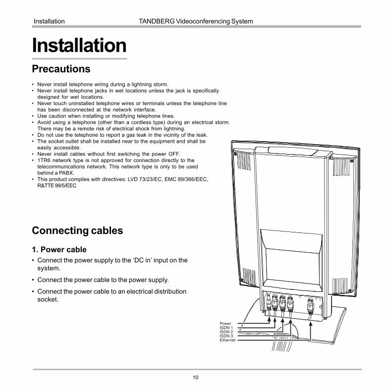
Connecting cables
Precautions� Never install telephone wiring during a lightning storm.� Never install telephone jacks in wet locations unless the jack is specifically
designed for wet locations.� Never touch uninstalled telephone wires or terminals unless the telephone line
has been disconnected at the network interface.� Use caution when installing or modifying telephone lines.� Avoid using a telephone (other than a cordless type) during an electrical storm.
There may be a remote risk of electrical shock from lightning.� Do not use the telephone to report a gas leak in the vicinity of the leak.� The socket outlet shall be installed near to the equipment and shall be
easily accessible.� Never install cables without first switching the power OFF.� 1TR6 network type is not approved for connection directly to the
telecommunications network. This network type is only to be usedbehind a PABX.
� This product complies with directives: LVD 73/23/EC, EMC 89/366/EEC,R&TTE 99/5/EEC
Installation
1. Power cable� Connect the power supply to the �DC in� input on the
system.
� Connect the power cable to the power supply.
� Connect the power cable to an electrical distributionsocket.

TANDBERG Videoconferencing System
11
Installation
2. ISDN cables� Connect the ISDN cables to the ISDN connectors on the system.
� Connect the ISDN cables to the ISDN sockets (S/T-interface) provided by the service provider. Your mainnumber will be the number associated with the socket to which ISDN cable number 1 is connected.
North America: The system does not have a built-in network terminator. If your wall socket provides you with an ISDNU-interface, you will need an NT1 between your system and your ISDN line.
3a. LAN cable� To use the system on LAN, connect a LAN cable from the �Ethernet� connector on the system to your LAN.
3b. Wireless LAN - Insert PC Card
� Remove the �dummy� card by pressing the �Eject� button next to the slot.� Insert the Wireless LAN PC Card.
NOTE: Make sure you insert the card in the right direction (see drawing). Push thecard into the slot until the �Eject� button pops up.
See �Wireless LAN Settings� for configuration.
SOME SOFTWARE VERSIONS DO NOT SUPPORT THREE ISDN LINESNOTE
WRITE DOWN THE NUMBERS ASSOCIATED WITH EACH OF THE ISDN LINES. YOU
WILL NEED THEM LATER TO CONFIGURE THE SYSTEM.NOTE

12
TANDBERG Videoconferencing SystemInstallation
System configuration
� Switch the system on by activating the power switch on the codec (located on the right hand side at the rear ofthe unit).
� After the system has performed a self-test routine, product logo and a �Welcome� menu will be displayed on themonitor.
connect
menu
� Enabled but unused ISDN lines (lines not active) should be disabled. Select the Quick Key �System Info� (onthe remote control) to view line status.
PRESS MENU ON THE REMOTE CONTROL. SELECT THE MENU �TERMINAL SETTINGS�, �ISDN SETTINGS�. SELECT THE RELEVANT �LINE SETUP�MENU AND SET �ENABLED: OFF�.
� Enter System Name to identify the system during an MCU conference. Select �Utilities�, �System Name� andenter the name using the number keys (as on a mobile phone).
� Select the language you want to use in �Terminal Settings�, �Language�.
� To activate a software option, enter an option key (see paperwork accompanying your system), see�Terminal Settings�, �Software Options�.
� Press CONNECT on the remote control. A dial tone should be heard if the network is active.
THESE SETTINGS ARE
ESSENTIAL FOR OPTIMAL
SYSTEM SET-UP.
NOTE

TANDBERG Videoconferencing System
13
Installation
ISDN configuration� Press MENU on the remote control. Select the menu �Terminal Settings�, then �ISDN Settings�.
Specify the settings for the selected network in one of the menus below.
For details, follow the instructions in chapter �ISDN-BRI Settings� in this manual.
LAN configuration� Press MENU on the remote control. Select the menu �Terminal Settings�, then �LAN Settings�.
Specify the necessary LAN settings according to the instructions from your LAN administrator. If there is anH.323 Gatekeeper present on your LAN, see also �H.323 Settings�.
For details, follow the instructions in chapter �LAN Settings� in this manual.

14
TANDBERG Videoconferencing SystemGetting started
Getting started
System start-upYour system should be in standby mode. When in standbymode, pressing any key or picking up the remote control willwake up the system. An incoming call will also wake up thesystem.
If the system does not respond, make sure the power cableis connected.
Welcome menuAfter the system has performed a self-test routine, productlogo and a �Welcome� menu will be displayed on themonitor. This menu should provide you with the mostimportant system information. The three color-codedcommands shown correspond with the Quick keys on theremote control. This means that to make a call, you canpress the green quick-key.

TANDBERG Videoconferencing System
15
Getting started
BasicsThe system�s most commonly used functions are accessible directly from the remote control by single keypresses. In addition, the user interface is represented by on-screen menus. Individual items within the menus andlists can be selected by moving a white highlighter bar to the desired option.
Quick keysThe three buttons on top of the remote control refer to the blocks at the bottom of thescreen. The text inside the blocks will change depending on which menu is selected.The three Quick keys have different colors.
Preset keysActivate pre-stored camera positions.
Video source keysActivate connected video sources.
Camera control and menu navigation keysFrequently used keys allowing you to control your own camera and the far end camera,control your volume, select and move self-view, switch your microphone off and navigatein the menu system.
Dialing keys / Preset keysUsed to make a call. The twelve number keys, (0-9), #, * operate in the same way ason a modern push-button telephone. These buttons are also used when entering a nameinto a text field.
Push-buttonThe push-button in front of the systemworks as the CONNECT button duringan incoming call.
When in a call, the button toggles thespeaker on/off.
When the speaker is off, the audio isavailable on the headset output,marked �Headset�, on the back of thesystem.

16
TANDBERG Videoconferencing SystemGetting started
Making and ending calls
Making a callTo make a call, enter the number or the IP-address of the unit you wish to call using the Dialing keysand press CONNECT.
The system will, by default, try to connect using Quality: Auto (see table overleaf). If the requested quality(bandwidth) cannot be established, the system will establish a connection on as high quality as possible.
The SoftMux ensures high reliability and includes the unique Downspeeding feature. If channels are droppedduring a meeting, Downspeeding automatically maintains the connection without interrupting the call in progress.The SoftMux also enables you to dial to other videoconferencing equipment, phones and mobile phones in thesame way and provides you with on-screen, real-time feedback on the progress of a call.
connect
LAN callTo make a call via a LAN, enter an IP-address by using a * as the �dot� in the IP-address, e.g. 123*3*0*12 will beinterpreted as 123.3.0.12. If a gatekeeper is present, you may place IP-calls using �telephone-style� numbers (anE.164 alias), according to the numbering plan implemented in the gatekeeper. The dialed number will then betranslated into an IP-address by the gatekeeper.

TANDBERG Videoconferencing System
17
Getting started
TIP
Access Code
If the system requires an Access Code, enter the code and press OK to proceed making a call:
Using sub-address / extension address / MCU passwordTo specify an ISDN sub-address or its LAN equivalent extension address (TCS-4), add a star (*) after the numberand then enter the sub-address/extension address.
Example: 12345678*10 ( <number>*<Sub-address/extension address/MCU password>)
When calling to external MCU�s requiring a password (TSC-1), this password can be added after the star (*). If nopassword is specified, a menu will prompt you to enter the password (after connected to the MCU).
SUB-ADDRESS IS USED TO ADDRESS DIFFERENT SYSTEMS ON THE SAME ISDN LINE.TCS-4 IS USED TO ADDRESS DIFFERENT SYSTEMS ON A LAN, WHEN DIALING IN VIA A GATEWAY.

18
TANDBERG Videoconferencing SystemGetting started
Selecting / setting default number of channels
Select Set as Default Set Restrict (56k)
The default call quality setting �Auto� will be used if no specific quality isselected.
To select quality (bandwidth):
� Press the �Quality� Quick Key when you are in the dial menu. TheQuality menu will then be displayed:
TYPE OF CALLSAuto 384kbps on ISDN/768kbps on IPMax 384kbps on ISDN/768kbps on IP768 768 kbps (IP only)512 512 kbps (IP only)384 384 kbps (6B)320 320 kbps (5B)256 256 kbps (4B)192 192 kbps (3B)128 128 kbps (2B)(Bonding/H.221)64 64 kbps (1B)(H.221)Teleph Telephone Call
SOME SYSTEMS AND SOFTWARE VERSIONS AND
NETWORKS DO NOT SUPPORT ALL BANDWIDTH
SELECTIONS.
NOTE
TIP
� Choose the preferred quality by selecting the desired call rate in the �Call Rate� field.
� You may also press the �Set as Default� Quick Key in order to make the selected bandwidth the defaultbandwidth for subsequent calls.
� Set �Set Restrict (56k)� to �On� to make a restricted call. An indicator �(56k)� will be shown behind the number.
RESTRICTED CALL A RESTRICTED CALL IS A CALL TO A 56 KBPS NETWORK. BY DEFAULT THE SYSTEM WILL DIAL AN UNRESTRICTED CALL (A CALL TO A64 KBPS NETWORK) AND DOWNSPEED TO 56KBPS IF NECESSARY. TO FORCE A RESTRICTED CALL, SELECT �SET RESTRICT (56K)�
TIP DIALING TWO NUMBERSSOMETIMES (ESPECIALLY WHEN CALLING TO AND WITHIN NORTH AMERICA) IT IS NECESSARY TO DIAL BOTH ISDN NUMBERS WHEN MAKING A VIDEO
CALL USING 2X64 KBPS OR 2X56 KBPS. SELECT �128� IN THE QUALITY MENU. WHEN YOU RETURN TO THE DIAL MENU, BOTH �NUMBER:� AND
�2ND:� ARE DISPLAYED. ENTER THE SECOND NUMBER.
TANDBERG Videoconferencing System
19
Getting started
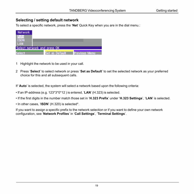
Selecting / setting default networkTo select a specific network, press the �Net� Quick Key when you are in the dial menu.:
1 Highlight the network to be used in your call.
2 Press �Select� to select network or press �Set as Default� to set the selected network as your preferredchoice for this and all subsequent calls.
If �Auto� is selected, the system will select a network based upon the following criteria:
� If an IP-address (e.g. 123*3*0*12 ) is entered, �LAN� (H.323) is selected.
� If the first digits in the number match those set in �H.323 Prefix� under �H.323 Settings�, �LAN� is selected.
� In other cases, �ISDN� (H.320) is selected*.
If you want to assign a specific prefix to the network selection or if you want to define your own networkconfiguration, see �Network Profiles� in �Call Settings�, �Terminal Settings�.
20
TANDBERG Videoconferencing SystemGetting started
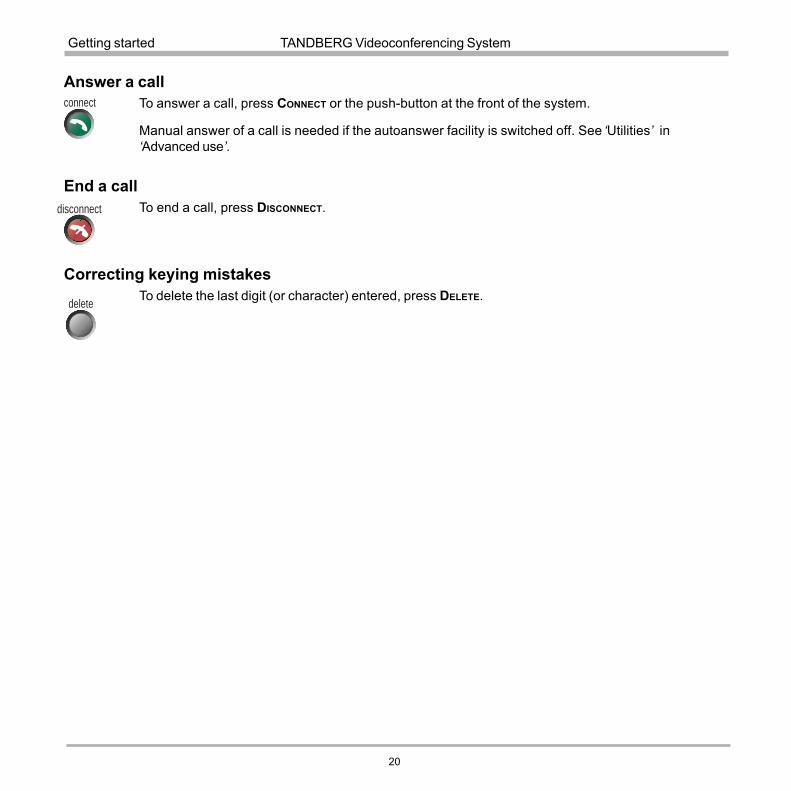
Answer a callTo answer a call, press CONNECT or the push-button at the front of the system.
Manual answer of a call is needed if the autoanswer facility is switched off. See �Utilities� in�Advanced use�.
End a callTo end a call, press DISCONNECT.
Correcting keying mistakesTo delete the last digit (or character) entered, press DELETE.
connect
disconnect
delete

TANDBERG Videoconferencing System
21
Getting started
To dial the selected entry press CONNECT. To edit the selected number before dialing, press OK.
DirectoryThe directory is a local phone book that stores up to 100 directory entries including the last number dialed. Theentries are sorted alphabetically. The entries can be point-to-point entries or MultiSite entries (see menu below).
By using the dataport file system or external management systems like the TANDBERG Management Suite, it ispossible to store 400 additional entries. These entries can only be changed from the dataport or the managementsystem.
When the system receives an incoming call and the calling party�s number is found in the directory, the callingparty�s name will be displayed instead of the number on the status line.
Press DIRECTORY to bring up the following menu:directory
connect
WHEN LAST NUMBER DIALED ISHIGHLIGHTED, THE SECOND QUICK KEY
STATES �STORE ENTRY�. THIS MAKES ITPOSSIBLE TO STORE LAST DIALED
NUMBER.
TO FIND AN ENTRY, KEY IN THE FIRST LETTER, FOR EXAMPLE T, AND SCROLL WITH
THE UP/DOWN ARROWS. THE LEFT/RIGHT ARROWS WILL MOVE ONE PAGE UP/DOWN.
TIP
TIP

22
TANDBERG Videoconferencing SystemGetting started
Add New EntryWhen selecting �Add New Entry�, an empty directory entry is displayed:
1 Move to �Name� and enter characters using the number keys on your remote control (as on mobile phones).Use �0� to enter �space�, use �#� to switch between upper- and lower case.
2 Move to �Number�, key in the number and press OK. Specify only one number. If two numbers are required,both numbers should be specified (2x64 or 2x56 calls).
3 Select �Quality� to specify call rate to be used.
4 Select �Set Restrict(56k)� to �On� to restrict the call rate. (A restricted call is a call to a 56Kbps network).
5 Select �Net� to specify the network profile to be used. See �Selecting / setting default network�.
6 Select �Save� to save the entry and return to the Directory menu.
Delete Entry
When �Delete Entry� is pressed, the selected entry is deleted.
Edit EntryTo edit an entry, highlight the entry you want to edit and press �Edit Entry�. Edit the entry and select �PreviousMenu� to return to the Directory menu.
Delete EntryTo delete an entry, highlight the entry and press DELETE.

TANDBERG Videoconferencing System
23
General use
mic off
Microphone on/offTo mute your microphone, press MIC OFF. An on screen indicator will appear.
Press MIC OFF to activate the microphone again.
Speaker on/offTo switch off your speaker in a call, press the push-button at the front of the system. An indicator will appear. Theheadset output, marked �Audio out�, on the back of the system will then provide the audio of the system. Thepush-button can also be used to accept a call.
move pip
General use
Adjusting volumePress the VOLUME keys to adjust the volume level. An on-screen indicator will show the current level.
View outgoing video (selfview)Press the SELFVIEW key to view your outgoing video.
To change the image being viewed on the monitor during a call press SELFVIEW until the desiredimage is shown (far end/selfview/still image or Duo Video).
Press MOVE PIP to move your selfview as a Picture-in-Picture to different corners of the screen or toswitch it off.
+
-
selfview

24
TANDBERG Videoconferencing SystemGeneral use
Do Not Disturb / Sleep ModePress any Quick key when not in a call to activate the Quick Menu.
When Do Not Disturb is activated, the system will not accept any incoming calls. The caller will hear a busytone when calling this unit. A status line will indicate when Do Not Disturb is active.
On Screen SymbolsThe system has a number of symbols signalling different settings.
This symbol will be shown when the volume is turned off on the system.
This symbol will be shown when the microphone is muted/turned off. It will also start to flash if audio isdetected in the room during a call.
When the system is On Air in a Multisite conference, this symbol will be shown.
This double padlock symbol will be shown when AES* encryption (Secure Conference) is active.
This padlock symbol will be shown when DES encryption (Secure Conference) is active.
This open padlock symbol is shown during the initialization phase for encryption. During this period thecall is not secure.
* Optional feature

TANDBERG Videoconferencing System
25
General use
OKzoom
Controlling the Main Camera
Moving / zooming cameraTo control the Main Camera use the keys below:
for pan/tilt and for zooming.
Selecting video sourcesPress: to select the video source to be transmitted to the far end.
Pressing �main cam� selects the built-in camera. Pressing any of the other keys selects the auxiliary video input.
doc cammain cam vcr pcaux
IF THE MENU SYSTEM IS ACTIVE, THE ARROW KEYS WILL NAVIGATE IN THE MENUS. IF �FARENDCAMERA� IS ACTIVATED, THE
FAR END CAMERA CAN BE CONTROLLED.TIP
THE TANDBERG 1000 CAMERA IS EQUIPPED WITH DIGITAL ZOOM. WHEN YOU ZOOM IN, THE RESOLUTION OF THE IMAGE WILL DECREASE,SOMETIMES CAUSING THE SELFVIEW IMAGE TO LOOK A BIT UNSHARP. THIS EFFECT HOWEVER WILL HARDLY BE NOTICEABLE ON THE RECEIVED IMAGE AT
THE FAR END.
NOTE
When Sleep Mode is selected, the following quick-keys are displayed:
Pressing �Sleep Now� puts the monitors in sleep mode. The system will still accept incoming calls.
Pressing �60 Minutes� or �3 Hours� will delay entering sleep mode accordingly.
Pressing any key or picking up the remote control will deactivate Do Not Disturb/Sleep Mode.
To see numbers, line status etc., select �System Info�. For further information see �Diagnostics� in �Advanceduse�.
WHEN SELECTING THE DOC CAM OR PC VIDEO SOURCES THE SYSTEM WILL AUTOMATICALLY REQUEST FLOOR WHEN CONNECTED TO AN EXTERNAL
MCU. THIS FEATURE CAN BE SWITCHED OFF IN THE UTILITIES MENU.NOTE
26
TANDBERG Videoconferencing SystemGeneral use
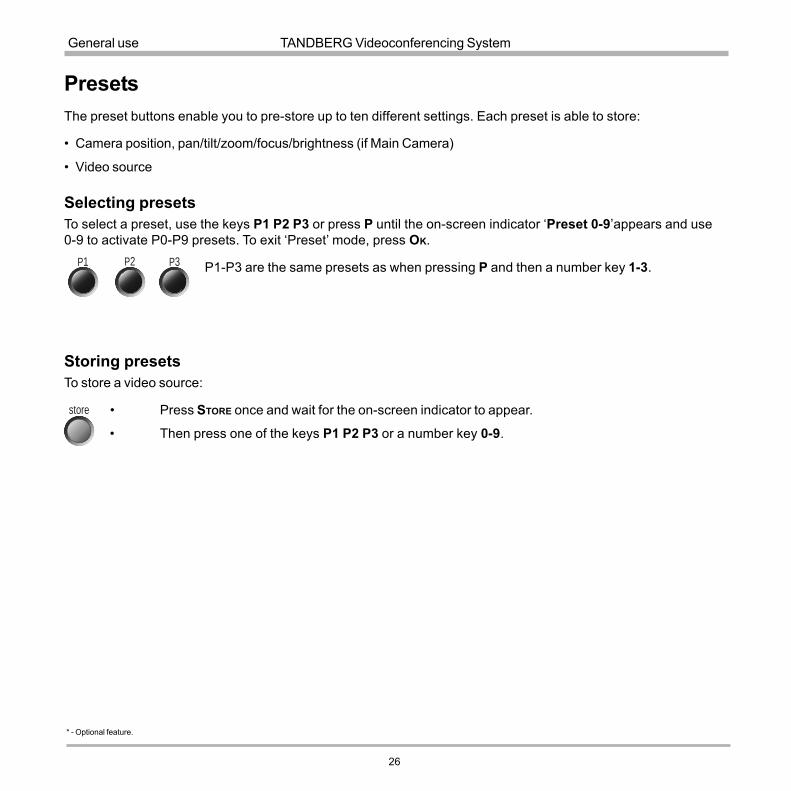
PresetsThe preset buttons enable you to pre-store up to ten different settings. Each preset is able to store:
� Camera position, pan/tilt/zoom/focus/brightness (if Main Camera)
� Video source
Selecting presetsTo select a preset, use the keys P1 P2 P3 or press P until the on-screen indicator �Preset 0-9�appears and use0-9 to activate P0-P9 presets. To exit �Preset� mode, press OK.
P1-P3 are the same presets as when pressing P and then a number key 1-3.
Storing presetsTo store a video source:
� Press STORE once and wait for the on-screen indicator to appear.
� Then press one of the keys P1 P2 P3 or a number key 0-9.
store
P1 P2 P3
* - Optional feature.

TANDBERG Videoconferencing System
27
General use
OK
Far end camera control (FECC)Press FAR END until the �FarEndCamera� on-screen indicator is displayed.
For this feature to operate the far end must support �Far end camera control� (H.281).
While activated you will be able to control the far end�s camera (pan/tilt/zoom/focus) and presets.
To control the far end camera use the keys below:
for pan/tilt and for zooming.
Far end presets can be activated by pressing the keys P1 P2 P3 or the number keys 0-9 to activate presets P0-P9.
Selection of far end videosources is achieved by pressing the buttons below when in FarEndCamera mode:
To prevent others controlling your camera, select �Far End Camera Control:Off� in �Utilities�.
zoom
doc cammain cam vcr pcaux
far end
NOTE IT DEPENDS ON THE FAR END SYSTEM CONFIGURATION IF THE FAR END DOCUMENT CAMERA IS DISPLAYED WHEN DOCCAM IS PRESSED.
PC SoftPresenter *PC SoftPresenter is used to display PC images on your system. The system and your PC must be connected toa LAN. In addition, VNC (Virtual Network Computing) server software must be installed on the PC.
To show the PC image:� Start the VNC software on your PC.� Press PC on your remote control. Use UP/DOWN to activate PAGE UP/PAGE DOWN on the PC.For setup information and details, see �VNC Settings� in �Advanced use�.

28
TANDBERG Videoconferencing SystemGeneral use
Sending/receiving snapshotsWhen a snapshot is sent, received or requested, it will be stored in the graphics memory. When a new snapshotis sent or received, the old snapshot will be erased. When disconnecting the call, the snapshot will be erased.
Sending a snapshot� Press SNAPSHOT.
Viewing a snapshotThe last sent or received snapshot will automatically be displayed on your screen.
� Press SELFVIEW to return to normal view.
Receiving a snapshotA received snapshot will automatically be displayed on your screen.
� Press SELFVIEW to return to normal view.
Requesting a snapshot� Press FAR END until the �FarEndCamera� on screen indicator is displayed.
� Press SNAPSHOT . A snapshot from the other side is automatically displayed.
snapshot WHEN CONNECTED TO AN EXTERNAL MCU, SENDING A SNAPSHOT WILL AUTOMATICALLY
INITIATE A FLOOR REQUEST.NOTE

TANDBERG Videoconferencing System
29
General use
External MCU control functionsA Multipoint Control Unit (MCU) enables several sites to participate in the same conference.
An MCU conference can have different modes:
Voice Switched means that the image of the person currently speaking will be broadcast to all the otherconference participants. This will remain the case until another participant starts to speak.
Continuous Presence shows several participants on the same screen at the same time.
Chairman Control functionality enables one participant to control the meeting by selecting which of theconference participants is to be broadcast to the other participants.
IN ORDER TO MAKE USE OF CHAIR CONTROL FEATURES THE MCU MUST SUPPORT CHAIR CONTROL (H.243).
TIP
TIP
DURING AN MCU CONFERENCE, A STATUS LINE WILL PROVIDE INFORMATION ABOUT THE CONFERENCE.TO REMOVE THIS STATUS LINE, SELECT �UTILITIES�, �MCU STATUS LINE: OFF�.
THIS SYSTEM DOES NOT HAVE A BUILT-IN MCU, BUT IT CAN CONNECT TO ANOTHER SYSTEM WITH MCU FUNCTIONALITY.THE SYSTEM CAN REMOTELY CONTROL EXTERNAL MCU FEATURES USING THE FUNCTIONS DESCRIBED BELOW.
NOTE

30
TANDBERG Videoconferencing SystemGeneral use
Quick Menu
PRESS ANY QUICK KEY WHEN IN A MULTIPOINT CONFERENCE TO ACTIVATE THE QUICK MENU.
This menu provides access to the most commonly used MCU functions.
If � Request Floor� is selected, �Request Floor� will change to �Release Floor�.
If � View Site#� is selected, �View Site #� will change to �End View�.
Selecting �Take Chair� will send a request to take chair. If granted, the Quick keys will be:
If �Floor to Site#� is selected, �Floor to Site#� will change to �Release Floor�.
If �Release Chair� is selected, you will return to the original Quick menu.
TIP
Request floorWhen requesting the floor, the MCU will broadcast your video in full screen to all other participants in theconference. If the MCU conference has a chairman, a floor request is sent to the chairman.
You will remain �On Air� until either you select �Release Floor� or the chairman decides to release the floor toanother participant.
FLOOR WILL AUTOMATICALLY BE REQUESTED WHEN SENDING A SNAPSHOT OR SELECTING THE DOC CAM OR PC VIDEO SOURCES.
Release floorYou choose �Release Floor� to take you �Off Air�. You should do this when you wish to make the floor available tothe other participants in the conference.
NOTE
TANDBERG Videoconferencing System
31
General use
Terminal Names
Allows you to see the site numbers or name (if supported) of other sites connected in the conference.
View site #Allows you to view any participant in the conference other than the participant currently �On Air�.
End view
Allows you to stop viewing the site previously chosen with �View Site #�, and returns your view to the site that iscurrently �On Air�.
Take chairAllows you to request chairmanship of the conference. If no one else is currently chairman the MCU will give youthe chair.
Release chairAllows you to relinquish the privileges of chairmanship of the conference.
Floor to site #Allows the chairman to select which of the conference participants is to be broadcast to all other participants.
Release FloorAllows the chairman to release the floor.

32
TANDBERG Videoconferencing SystemGeneral use
* - Please contact your TANDBERG representative for further information.
Web-interfaceIt is possible to access and maintain the system remotely via a local area network (LAN) using a standard Web-browser.
Connect your system to a local area network.
Configure your codec:
� Press MENU, select �Terminal Settings�, �LAN Settings�
� Specify IP-assignment �DHCP� or �Static�. If DHCP is selected no other settings are needed. If Static isselected, �IP-address�, �IP-subnet mask� and �Gateway� must be specified.
Example:IP-assignment: StaticIP-address: 196.9.200.129IP-subnet mask: 255.255.255.0Gateway: 196.9.200.21
See �LAN Settings� in �Advanced use� for further information.
� Start your Web-browser. In the address field type the IP-address of the codec. Enter the password and theWeb-page of the codec will be shown. The default password is �TANDBERG�.
THE SYSTEM MUST BE RESTARTED BEFORE CHANGES IN THE
�LAN SETTINGS� MENU CAN TAKE EFFECT.NOTE
Text Chat / Closed CaptioningWhile in an ISDN or IP call to another system supporting Text Chat (T.140), select �Text Chat� from the Web-pageof the codec. Enter text in the window displayed. When selecting �Send Text�, the text will be displayed on thelocal and far-end monitor as shown below:
The local Text Chat window can be closed manually from the Web-interface by pressing �Close Window�. It willalso close automatically after a few minutes without activity.

TANDBERG Videoconferencing System
33
General use
T.120 / data Dataport 1COM port
T.120 and other PC applicationsA PC can be connected to the system using a serial cable. This will enable interactive editing, file transfer andapplication sharing between two computers.
Appropriate communication software should be used (for example: Microsoft NetMeeting, Intel ProShare Premier,Windows HyperTerminal, Procomm Plus and so forth.)
The system has been specially designed to work with interactive programs andincludes a data channel that can send and receive data to and from the far end atspeeds of up to 38,400 baud.
StreamingTo view streaming, select �Streaming� from the Web-page of the codec. See separate �Streaming� section inthis manual for further information.
PC SoftPresenter *PC SoftPresenter is used to display PC images on your system without using a VGA cable. The system and yourPC must be connected to a LAN. In addition, VNC (Virtual Network Computing) server software must be installedon the PC.
To show the PC image:� Start the VNC software on your PC.� Press PC on your remote control. Use UP/DOWN to activate PAGE UP/PAGE DOWN on the PC.For setup information and details, see �VNC Settings� in �Advanced use�.
�PC: VNC� MUST BE SET IN �VIDEO SETTINGS�.NOTE
* - Optional feature.
SnapshotsSnapshots of current stream, selfview, and far end streams are accesible via http. See Appendix 5 fordescriptions of the possible snapshot files.
34
TANDBERG Videoconferencing SystemAdvanced use
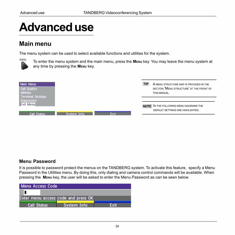
Main menuThe menu system can be used to select available functions and utilities for the system.
To enter the menu system and the main menu, press the MENU key. You may leave the menu system atany time by pressing the MENU key.
Menu PasswordIt is possible to password protect the menus on the TANDBERG system. To activate this feature, specify a MenuPassword in the Utilities menu. By doing this, only dialing and camera control commands will be available. Whenpressing the MENU key, the user will be asked to enter the Menu Password as can be seen below.
menu
Advanced use
A MENU STRUCTURE MAP IS PROVIDED IN THE
SECTION �MENU STRUCTURE� AT THE FRONT OF
THIS MANUAL.
IN THE FOLLOWING MENU DIAGRAMS THE
DEFAULT SETTINGS ARE HIGHLIGHTED.
TIP
NOTE

TANDBERG Videoconferencing System
35
Advanced use
Call qualityThe Call Quality menu allows you to select the preferred quality of your call.
DUE TO ACTIONS OR LIMITATIONS AT THE FAR END YOU MAY NOT ALWAYS BE ABLE TO ACHIEVE THE SELECTIONS YOU WANT.
AudioAuto Optimized audio quality depending on bandwidth.High High audio quality (G722) regardless of bandwidth.Normal Telephone quality (G728) regardless of bandwidth.Off No audio is transmitted.
VideoAuto Will select �Motion� or �Sharpness� depending on selected video source**.Motion Optimized for smooth motion video for all video inputs.Sharpness Optimized for sharp video for all video inputs.
H.264*Auto Optimized video quality depending on what is available.Off H.264 video compression and decompression will not be used.
VGA ResolutionsAuto VGA capabilities (VGA/SVGA/XGA*) and SIF capabilities will be transmitted and enabled.Off VGA capabilities will not be transmitted. Useful if far end can not handle these capabilities.
SIF CAPABILITIES WILL ENABLE BETTER VIDEO QUALITY FOR NTSC SYSTEMS (SIF: 352X240, ISIF: 352X480, 4SIF: 704X480).
AUTO
1-4 CHANNELS: G722.1 IS SELECTED.5 OR MORE CHANNELS: G722 IS SELECTED.
NOTE
TIP
TIP
* - E2 only

36
TANDBERG Videoconferencing SystemAdvanced use
Utilities
AutoanswerOn: The system will automatically answer all incoming calls.
On+MicOff: The system will automatically answer all incoming calls and switch the microphone offwhen the call is connected. Press MICOFF to switch the microphone on.
Off: You must manually answer all incoming calls by pressing the CONNECT key.
Far end camera controlOn: The far end will be able to:
� Control your camera� Select your video sources� Activate your presets� Request snapshots
Off: None of the four features above on the local system can be accessed by the other side, however you willstill be able to control the camera on the far end.
Welcome MenuOn: A �Welcome menu� with useful information on how to use the system will be displayed. See �Gettings
started� section.
Off: The Welcome menu� will not be displayed.
Logo: If a logo is uploaded to the system, it will be shown if this button is selected. See Appendix 4.

TANDBERG Videoconferencing System
37
Advanced use
MCU status lineOn: The MultiSite/MCU/DuoVideo indicators will be displayed and provide information about the conference.
Off: The MultiSite/MCU/DuoVideo indicators will not be displayed.
Auto: The MultiSite/MCU/DuoVideo indicators will be displayed for a few seconds and then timed out. Whengrabbing the remote control, the indicators will be shown again.
System NameIdentifies the system:
� during an MCU conference call.� when using the Web-interface.� when the codec is acting as an SNMP Agent.� towards a DHCP server.� as an H323 ID.
Menu PasswordEnter the code whch should be entered to get access to the menus on the TANDBERG system. When pressingthe �Menu� button on the remote control, the user will be asked to enter the Password written here.
Camera BrightnessTo manually adjust the brightness select �Manual� and use the arrow keys to adjust.
Monitor BrightnessTo manually adjust the brightness select �Manual� and use the arrow keys to adjust.
WhitebalanceTo manually adjust the whitebalance select �Manual� and use the arrow keys to adjust.

38
TANDBERG Videoconferencing SystemAdvanced use
Web SnapshotsThe system is able to generate JPEG snapshots and provide them to the world outside by request (as �http get� orvia ftp). See Appendix 5 for descriptions of the possible snapshot files.
On: Snapshots generation is enabled.Off: Snapshots generation is disabled.
SNAPSHOTS ARE NOT GENERATED IF THE CONFERENCE IS SECURE.NOTE
Auto Request FloorOn When selecting �Doc Cam� or �PC� video sources, the system will automatically Request Floor when
connected to a MCU conference.
Off When selecting �Doc Cam� or �PC� video sources, the system will not Request Floor.

TANDBERG Videoconferencing System
39
Advanced use
Terminal SettingsThis menu provides basic network setup for the system and should be used when installing the system.
ISDN-BRI Settings
SOME SOFTWARE VERSIONS DO NOT SUPPORT 3ISDN LINES AND SOME OF THE LINE SETUP LINES
WILL BE GRAYED OUT.
IF NATIONAL ISDN IS SELECTED, PRESS THE QUICK
KEY �AUTO BRI CONFIG� TO REQUEST AN AUTOMATIC
CONFIGURATION OF THE LINE & SPID SETTINGS
(SWITCH MUST SUPPORT GR-2941-CORE).
MANDATORY ISDN-BRI SETTINGS
TO MAKE SURE YOUR SYSTEM WILL WORK PROPERLY USING ISDN-BRI, MAKE THE FOLLOWING SETTINGS:- SET ISDN SWITCH TYPE
- ENTER ISDN LINE NUMBERS (+ SPIDS IF REQUIRED)- DISABLE UNUSED LINES
NOTE
NOTE
NOTE

40
TANDBERG Videoconferencing SystemAdvanced use
ISDN switch type
Select the type of ISDN network connected to your unit.
Line setupThis menu allows you to program the numbers associated with your ISDN line.
If you want to use this ISDN line, you need to set �Enabled: On� and enter the numbers of your ISDN line. If someof the ISDN lines are not to be used, set �Enabled: Off�. Line 1 should always be enabled.
National ISDN and AT&T Custom ISDN might require SPID numbers associated with your ISDN numbers. If youhave received two different SPID numbers for each ISDN line from your telephone company, you must programboth.
Example:
Numbers SPIDSISDN BRI 1: 67838498 016783849800
67838498 016783849810ISDN BRI 2: 23478060 012347806000
23478070 012347807000ISDN BRI 3: 23478420 012347842000

TANDBERG Videoconferencing System
41
Advanced use
Advanced ISDN settings
SubaddressUsing a subaddress enables you to connect up to eight ISDN terminals to the same ISDN telephone numberand line. The terminals are addressed by using different subaddresses.
To call a terminal with a subaddress, separate the ISDN telephone number and the subaddress with a �*�.
Example: 12345678*2 (Up to four digit subaddresses are possible)
THIS SERVICE HAS LIMITED ACCESS ON SOME ISDN NETWORKS.NOTE

42
TANDBERG Videoconferencing SystemAdvanced use
MSN (Multiple Subscriber Number)The use of MSN (Multiple Subscriber Number) enables you to attach different ISDN terminals, with different numbers,to the same physical ISDN telephone line. If �Validate Numbers� is set to �On� only calls to those numbers specifiedin the Line Setup menus will be answered. This service can be ordered from your telephone company.
Parallel dial
On Channels will be dialed and connected in parallel when setting up a BONDING call.
Off Channels will be dialed one by one which may increase the dialing time.
Send Own Numbers
On The system will send its own numbers to the far end.
Off The system will not send its own numbers to the far end, but please note that the network may still sendyour numbers to the far end.
Sending Complete
On The system will send the ISDN message information element �Sending Complete�.
Off The system will not send �Sending Complete�.
Line 1 Setup, Number1: 600Validate Numbers (MSN): On
ISDN line number 12345600 / 601 / 602 Call 12345601
Ringing
Line 1 Setup, Number1: 601Validate Numbers (MSN): On
Line 1 Setup, Number1: 602Validate Numbers (MSN): On

TANDBERG Videoconferencing System
43
Advanced use
AddressAddress is defined as the IP-address of a streaming client, streaming server or a multicast address. Giving anaddress in the range 224.0.0.1-239.255.255.255 will broadcast the stream to any host that has joined thespecified multicast group. Specifying normal broadcast address 255.255.255.255 will broadcast to anymembers on the LAN.
Address PortIf several codecs are streaming to the same IP-address, different ports have to be used in order for the client toknow which stream to receive. If the first codec streams on port 2240 and the second codec on port 2250, theclient has to specify which port to listen to. Video is transmitted on the specified port, audio is transmitted onthe port number 4 above the specified video port, in this case 2244 and 2254.
* - Please contact your TANDBERG representative for further information.
Streaming*
WHEN STREAMING, A CALL CAN NOT BE MADE.NOTE
LAN Settings
AN ON-SCREEN INDICATOR IS SHOWN WHEN
STREAMING IS ACTIVE.NOTE

44
TANDBERG Videoconferencing SystemAdvanced use
Allow Remote Start
On Streaming can be started from external user interfaces like the Web-browser or Telnet session.Off Streaming can only be started from the Video Conferencing System using the remote control, or byusing the Dataport. This will prevent activation of streaming using Web browser or Telnet sessions.
AnnouncementsOn The codec will announce to the network that it is streaming. This enables a streaming client (e.g. a PC)
to connect to the codec�s streaming session. Used by Cisco IP/TV.Off No announcement packets will be transmitted.
Video RateDefines the Video streaming rate from the system. Range is 16kbps - 320kbps. In addition, audio (G.711)streaming rate is 64kbps, providing a maximum streaming rate of 384kbps.
PasswordSet password so that only participants entering correct password will be able to view the streaming session.Entering a password will prevent unauthorized people from accessing the streaming session.
Start/Stop StreamingBy pressing the Quick Key labeled � Start Streaming �, the Streaming session will start. To stop the stream, pressthe same quick-key, which will be labeled � Stop Streaming � while the streaming-session is active. PressingDisconnect will also stop the streaming session.
How to view streamingAfter streaming is started, an easy way to view the streamed audio/video is to start your Web-browser and enterthe IP-address of the streaming system. After the Web page of the codec is shown, click on �Streaming�.Alternatively, enter http://<codec ip-address>/stream.sdp.
TTL/Router HopsThis is used for streaming data to limit how many routers the data should pass before it is rejected. If TTL is setto 2, data will not traverse more than 2 router hops.
TANDBERG Videoconferencing System
45
Advanced use
H.323 Settings
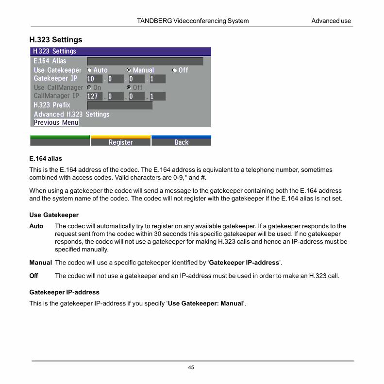
E.164 alias
This is the E.164 address of the codec. The E.164 address is equivalent to a telephone number, sometimescombined with access codes. Valid characters are 0-9,* and #.
When using a gatekeeper the codec will send a message to the gatekeeper containing both the E.164 addressand the system name of the codec. The codec will not register with the gatekeeper if the E.164 alias is not set.
Use GatekeeperAuto The codec will automatically try to register on any available gatekeeper. If a gatekeeper responds to the
request sent from the codec within 30 seconds this specific gatekeeper will be used. If no gatekeeperresponds, the codec will not use a gatekeeper for making H.323 calls and hence an IP-address must bespecified manually.
Manual The codec will use a specific gatekeeper identified by �Gatekeeper IP-address�.
Off The codec will not use a gatekeeper and an IP-address must be used in order to make an H.323 call.
Gatekeeper IP-addressThis is the gatekeeper IP-address if you specify �Use Gatekeeper: Manual�.

46
TANDBERG Videoconferencing SystemAdvanced use
Use CallManager
On The codec will use a specific Cisco CallManager identified by the IP-address specified in �CallManagerIP�. The CallManager replaces a gatekeeper, therefore �Use Gatekeeper� must be set to �Off� before thiscan be done. When �On�, �Use Gatekeeper� and �Gatekeeper IP� is disabled.
Off The codec will not use Cisco CallManager.
CallManager IPThe CallManager IP-address specified here will be used if �Use CallManager: On�.
H.323 PrefixWhen dialing a number prefixed with digits specified by �H.323 Prefix�, and with �Net: Auto�, an H.323 call will beplaced. Example: H.323 Prefix is �555�. Dialling �55582� with �Net:Auto� will select LAN.
RegisterPressing �Register� will send a gatekeeper registration request. This request will also be sent when leaving themenu.

TANDBERG Videoconferencing System
47
Advanced use
Advanced H.323 Settings
THESE SETTINGS ONLY HAVE AN
EFFECT IF THEY ARE SUPPORTED BY
YOUR IP INFRA STRUCTURE.
NOTE
RSVPAuto Resource Reservation Protocol enables the endpoints to request the optimal amount of bandwidth for the
duration of an IP video conference.Off Resource Reservation Protocol is switched off.NATNAT, Network Address Translation, is used in small LAN�s, often home offices, when a PC and avideoconferencing system is connected to a router with NAT support. NAT support in the videoconferencingsystem enables proper exchange of audio/video data when connected to an external videoconferencing system(when the IP traffic goes through an NAT router.
When NAT is On, the NAT Server Address will be shown in the startup-menu: �My IP Address: 10.0.2.1 (NAT)�
NAT AddressThis must be the external/global IP-address to the router with NAT support. Packets sent to the router will then berouted to the codec.
In the router, the following ports must be routed to the codec�s IP-address:Port 1720Port 5555-5560Port 2326-2365Please contact your TANDBERG representative for further information.
H.323 PortsStatic When selecting static H323 ports for TCP connections the ports 5555 or 5556 will be used for
Q931 and H245 respectively.Dynamic The operating system will allocate which ports to use when opening a TCP connection.. The
reason for doing this is to avoid using the same ports for subsequent calls as some firewallsconsider this as a sign of attack.

48
TANDBERG Videoconferencing SystemAdvanced use
IP PrecedenceUsed to define which priority audio, video, data and signalling should have in the network. Higher numbers indicatehigher priority. The priority ranges from 0(off) - 7 for each type of packets .
DiffservUsed to define which priority Audio, Video, Data and Signaling packets should have in an IP network. The priorityranges from 0 to 63 for each type of packets.
IP Type of Service (TOS)Helps a router select a routing path when multiple paths are available.
Delay Tells the router to minimize the delayThroughput Tells the router to maximize the throughputReliability Tells the router to maximize the reliabilityCost Tells the router to minimize the cost
Auto will provide the following priority:Audio 4Video 4Data 3Signalling 6
QoS TypeOff No QoS is used
Diffserv Diffserv QoS method is used. Please see below for details.
IP Precedence IP Precedence QoS method is used. Please see below for details.

TANDBERG Videoconferencing System
49
Advanced use
IP Settings
IP-assignmentDHCP (Dynamic Host Configuration Protocol) can be selected when a DHCP server is present.
DHCP: IP-address, IP-subnet mask and Gateway are not used because these parameters are assigned bythe DHCP server.
Static: The codec�s IP-address and IP-subnet mask must be specified in the IP-address field.
IP-address
IP-address defines the network address of the codec. This address is only used in static mode. In DHCP-mode,the assigned IP-address can be found on the Welcome Menu.
IP-subnet maskIP-subnet mask defines the type of network. This address is only used in static mode. Your LAN-administrator willprovide the correct value for this field.
Gateway
When using DHCP, the default gateway will be set automatically. If the LAN utilizes static IP addresses, IPaddress, subnet mask, and default gateway must be specified by the LAN administrator.
CHANGES IN THIS MENU WILL NOT HAVE
ANY EFFECT BEFORE THE SYSTEM ISRESTARTED.
NOTE
50
TANDBERG Videoconferencing SystemAdvanced use
Ethernet Speed
Auto The codec will auto-detect the speed/duplex on the LAN.10/Half The codec will connect to the LAN using 10Mbps speed/Half Duplex.10/Full 10 Mbps speed/Full Duplex.100/Half 100 Mbps speed/Half Duplex.100/Full 100 Mbps speed/Full Duplex.
RestartPressing the Quick key �Restart� will restart your system without having to use the On/Off switch on the codec. IfIP-assignment is changed, it is sufficient to use this Quick key to restart the system.
TANDBERG Videoconferencing System
51
Advanced use
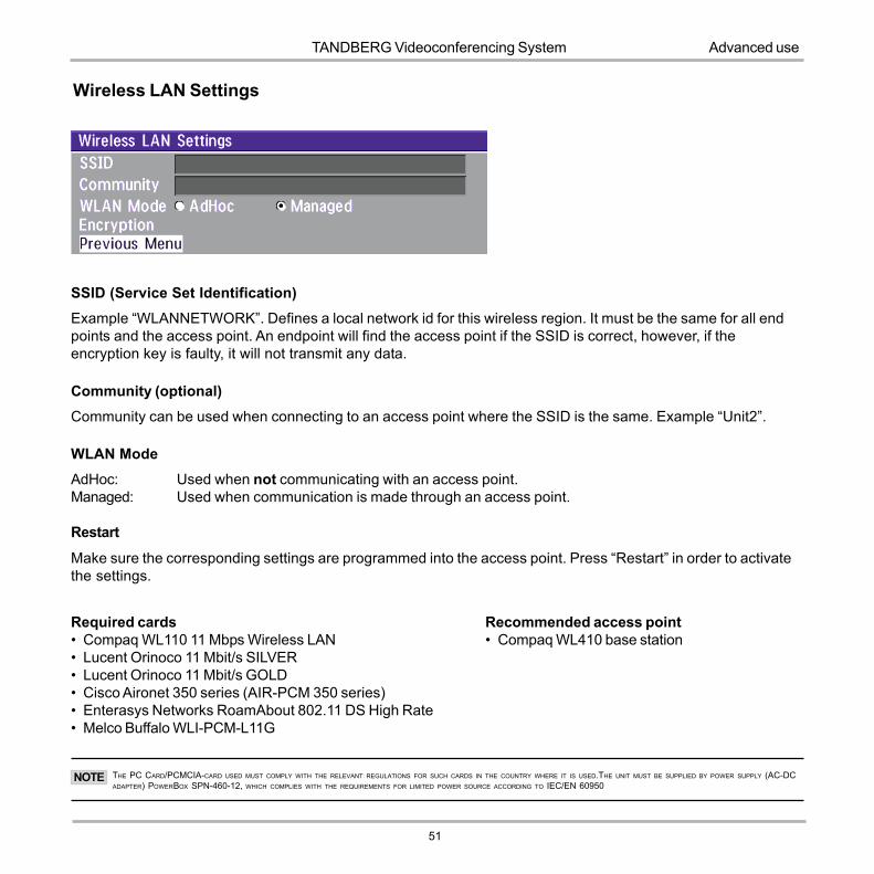
Wireless LAN Settings
SSID (Service Set Identification)Example �WLANNETWORK�. Defines a local network id for this wireless region. It must be the same for all endpoints and the access point. An endpoint will find the access point if the SSID is correct, however, if theencryption key is faulty, it will not transmit any data.
Community (optional)Community can be used when connecting to an access point where the SSID is the same. Example �Unit2�.
WLAN ModeAdHoc: Used when not communicating with an access point.Managed: Used when communication is made through an access point.
Restart
Make sure the corresponding settings are programmed into the access point. Press �Restart� in order to activatethe settings.
Required cards� Compaq WL110 11 Mbps Wireless LAN� Lucent Orinoco 11 Mbit/s SILVER� Lucent Orinoco 11 Mbit/s GOLD� Cisco Aironet 350 series (AIR-PCM 350 series)� Enterasys Networks RoamAbout 802.11 DS High Rate� Melco Buffalo WLI-PCM-L11G
Recommended access point� Compaq WL410 base station
THE PC CARD/PCMCIA-CARD USED MUST COMPLY WITH THE RELEVANT REGULATIONS FOR SUCH CARDS IN THE COUNTRY WHERE IT IS USED.THE UNIT MUST BE SUPPLIED BY POWER SUPPLY (AC-DCADAPTER) POWERBOX SPN-460-12, WHICH COMPLIES WITH THE REQUIREMENTS FOR LIMITED POWER SOURCE ACCORDING TO IEC/EN 60950
NOTE

52
TANDBERG Videoconferencing SystemAdvanced use
Encryption
Encryption using Hex numbersThe 64-bit keys can consist of 10hexadecimal digits. Example:�de01ad4dbe�. The 128-bit key canconsist of 26 hex numbers.
EncryptionSelect if you want to encrypt your Wireless LAN connection.
Use KeySelect which of the keys shown below you want to use.
Key 1-4The 64-bit keys can consist of a leading star (*) and 5 characters.The 128-bit key can consist of a leading star (*) and 13 characters.
Start with a * and then the text. Example: 128 bit key: *secretkeyhome.
INCREASED ENCRYPTION LEVEL WILL DECREASE PERFORMANCE.NOTE

TANDBERG Videoconferencing System
53
Advanced use
NOTE
SNMP Trap HostSNMP (Simple Network Management Protocol) is used for monitoring and configuring of different units in anetwork. The codec�s SNMP Agent responds to requests from SNMP Managers (a PC program etc.). SNMPtraps are generated by the agent to inform the manager about important events.
SNMP Trap Host identifies the IP-address of the SNMP manager.
Traps can be sent to multiple SNMP Trap Hosts. Enter the IP address of up to three SNMP managers. All trapswill then be sent to the hosts listed.
SNMP Community
SNMP Community names are used to authenticate SNMP requests. SNMP requests must have a �password� inorder to receive a response from the SNMP agent in the codec.
THE SNMP COMMUNITY NAME IS CASE SENSITIVE.
SNMP Settings

54
TANDBERG Videoconferencing SystemAdvanced use
Audio Settings
Video Call Alert Tone / Alert VolumeDifferent ringing tones may be selected. You may also select different volume levels for the ringing tone.
Key TonesThe Key Tones may be switched on and off.
TANDBERG Videoconferencing System
55
Advanced use
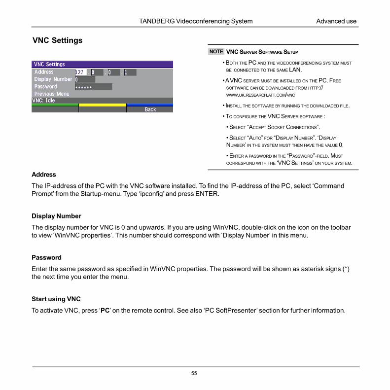
AddressThe IP-address of the PC with the VNC software installed. To find the IP-address of the PC, select �CommandPrompt� from the Startup-menu. Type �ipconfig� and press ENTER.
Display Number
The display number for VNC is 0 and upwards. If you are using WinVNC, double-click on the icon on the toolbarto view �WinVNC properties�. This number should correspond with �Display Number� in this menu.
PasswordEnter the same password as specified in WinVNC properties. The password will be shown as asterisk signs (*)the next time you enter the menu.
Start using VNC
To activate VNC, press �PC� on the remote control. See also �PC SoftPresenter� section for further information.
VNC SettingsVNC SERVER SOFTWARE SETUP
� BOTH THE PC AND THE VIDEOCONFERENCING SYSTEM MUST
BE CONNECTED TO THE SAME LAN.
� A VNC SERVER MUST BE INSTALLED ON THE PC. FREE
SOFTWARE CAN BE DOWNLOADED FROM HTTP://WWW.UK.RESEARCH.ATT.COM/VNC
� INSTALL THE SOFTWARE BY RUNNING THE DOWNLOADED FILE.
� TO CONFIGURE THE VNC SERVER SOFTWARE :
� SELECT �ACCEPT SOCKET CONNECTIONS�.
� SELECT �AUTO� FOR �DISPLAY NUMBER�. �DISPLAY
NUMBER� IN THE SYSTEM MUST THEN HAVE THE VALUE 0.
� ENTER A PASSWORD IN THE �PASSWORD�-FIELD. MUST
CORRESPOND WITH THE �VNC SETTINGS� ON YOUR SYSTEM.
NOTE

56
TANDBERG Videoconferencing SystemAdvanced use
Call Settings
Incoming telephone callsOn: The system will accept incoming telephone calls.Off: The system will not accept incoming telephone calls. This is useful to prevent incoming calls from
systems other than videoconferencing systems.
Fallback to telephonyOn Enables fallback from video calls to telephony/speech calls.Off Disables fallback.
Access CodeOn When pressing CONNECT or any number to make a call, an Access Code menu will be shown. The
user will then have to enter the correct Access Code in order to make a call.Off No Access Code is necessary to make a call.

TANDBERG Videoconferencing System
57
Advanced use
Encryption (Secure Conference)*Auto The system will try to set up calls using encryption.
Point to point calls: If the far end system supports encryption, the call will be encrypted. If not, thecall will proceed without encryption.
ISDN MultiSite calls: In order to have encrypted MultiSite calls on ISDN, all sites must supportencryption. The padlock symbol will indicate encryption mode (AES* or DES). If there is a mix ofAES* and DES encryption, only the symbol for DES encryption (single padlock) will be displayed.
IP MultiSite calls: Sites supporting encryption will be encrypted and sites not supporting encryptionwill not be encrypted. The padlock symbol will be shown on the MultiSite if all sites supportencryption. The padlock symbol will be shown on the site connected to the MultiSite if thisconnection to the MultiSite is encrypted.
If the far end supports encryption, the systems will initiate encryption after the call is connected (an�open padlock� symbol will be displayed). When encryption has been established, a �closed padlock�symbol will be displayed.
Off The system will not send or receive encrypted data.
Technical encryption information like encryption algorithm and encryption check code can be found in the �CallStatus� menu.
Encryption ModeAuto The system will try to use the most secure encryption - AES, dependent on the capabilities of the
other site. If AES encryption is not supported by the other site, DES encryption will be tried.
AES* The system will try to use AES with 128 bits encryption when setting up ISDN or IP calls. If AES isnot supported by the other site, no other type of encryption will be initiated.
DES The system will always try to set up the call using DES with 56 bits encryption on ISDN and IP. IfDES is not supported by the other site, no other type of encryption will be initiated.
* Optional feature
BOTH AES* AND DES ENCRYPTION IS SUPPORTED FOR MIXED ISDN/IP CALLS. IN ADDITION AES* -AND DES ENCRYPTED SITES CAN BE
CONNECTED AT THE SAME TIME.TIP

58
TANDBERG Videoconferencing SystemAdvanced use
Network ProfilesThis menu defines the settings listed when pressing the Quick key �Net:� while in the dial menu.
Max Call LengthThis feature will automatically end both incoming and outgoing calls when the call time exceeds the �Max CallLength� specified.
Max Call Length can have the following values: 0-999(minutes), where 0 is Off.
A few minutes before the specified time is reached, a Quick-Key menu will appear. Users will be asked if he/shewants to extend the specified �Max Call Length�:

TANDBERG Videoconferencing System
59
Advanced use
This menu consists of 6 network profiles, a prefix can be added for each profile. If you add a prefix to a profile, thisprefix will automatically be added to the number being dialed.
EXAMPLE: 0 IS ADDED AS A CALL PREFIX TO THE 2ND PROFILE, ISDN. IF YOU ENTER 12345678 IN THE DIAL MENU AND SELECT �ISDN�, THE
NUMBER DIALED WILL BE 012345678.
Using the three last profiles you can enter the name of a profile, prefix and network selection. This is useful if youhave a fixed prefix for your service provider.
60
TANDBERG Videoconferencing SystemAdvanced use
Modem modeAllows you to control the system externally via a PC as in Control Mode. Once a call is established, Dataport 1will automatically switch to Data mode. When the call disconnects, Dataport 1 switches back to Control mode.
T.120Provides a data channel supporting the T.120 standard for data communication. Using T.120 software on your PC,you can communicate with other T.120 systems using your PC and your system.
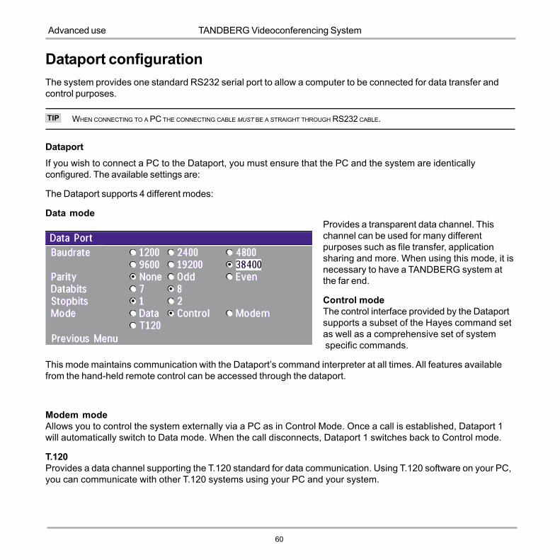
Dataport configurationThe system provides one standard RS232 serial port to allow a computer to be connected for data transfer andcontrol purposes.
WHEN CONNECTING TO A PC THE CONNECTING CABLE MUST BE A STRAIGHT THROUGH RS232 CABLE.
DataportIf you wish to connect a PC to the Dataport, you must ensure that the PC and the system are identicallyconfigured. The available settings are:
The Dataport supports 4 different modes:
Data modeProvides a transparent data channel. Thischannel can be used for many differentpurposes such as file transfer, applicationsharing and more. When using this mode, it isnecessary to have a TANDBERG system atthe far end.
Control modeThe control interface provided by the Dataportsupports a subset of the Hayes command setas well as a comprehensive set of system specific commands.
This mode maintains communication with the Dataport�s command interpreter at all times. All features availablefrom the hand-held remote control can be accessed through the dataport.
TIP

TANDBERG Videoconferencing System
61
Advanced use
Software OptionsThe system requires a valid option key to activate Security (contains Secure Conference AES) and/or Presenterfunctionality.
A restart of the system is required after entering a new option key. If the option key is invalid, the original key willbe used.
LanguageThe system supports 11 different languages for its on-screen menus.
Select the preferred language, and then press OK to save.
The following options are available1. No option2. PP (Presenter)3. Security + PP

62
TANDBERG Videoconferencing SystemAdvanced use
DiagnosticsAllows testing of individual system components and displays the current system settings.
OK
System infoSelect � System Info� to view system numbers, line status, software version and other usefulinformation.
Channel status
Comprehensive information about the call progress is available through the Channel Status window.This window indicates the various stages each B-channel goes through whilst establishing a connection.
Status - BRI CommentsIdle the channel is idleCalling when calling � the network has acknowledged the callConnected when connection is establishedSync when the channels are synchronisedActive when all available channels are connectedReleasing waiting for the network to confirm a release of the callReleased when disconnected - the network has acknowledged the disconnection

TANDBERG Videoconferencing System
63
Advanced use
The numbers used to call out to the far end are shown in the window. If an error occurs a cause code will bedisplayed on the right hand side of the window.
PRESS MENU, �CALL STATUS�, �CHANNEL STATUS� TO BRING THIS MENU UP WHEN NOT IN THE MENU SYSTEM.TIP
Cause codesThe most common cause codes (for ISDN) are:
1 - Unallocated (unassigned) number2 - No route to specified transit network (WAN)16 - Normal clearing17 - User busy18 - No user responding21 - Call rejected28 - Invalid number format (incomplete number)29 - Facility rejected31 - Normal, unspecified34 - No circuit/channel available41 - Temporary failure58 - Bearer capability not presently available65 - Bearer service not implemented69 - Requested facility not implemented81 - Invalid call reference value88 - Incompatible destination100 - Invalid information element contents102 - Recovery on timer expiry127 - Internetworking, unspecified
255 - TANDBERG specific. Undefined cause code
64
TANDBERG Videoconferencing SystemAdvanced use
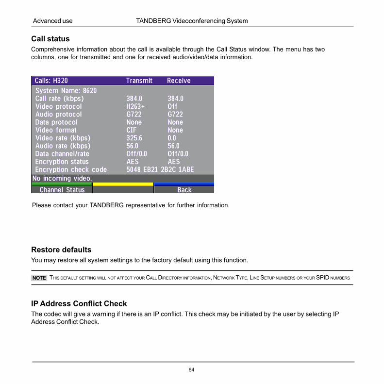
Call statusComprehensive information about the call is available through the Call Status window. The menu has twocolumns, one for transmitted and one for received audio/video/data information.
Please contact your TANDBERG representative for further information.
Restore defaultsYou may restore all system settings to the factory default using this function.
THIS DEFAULT SETTING WILL NOT AFFECT YOUR CALL DIRECTORY INFORMATION, NETWORK TYPE, LINE SETUP NUMBERS OR YOUR SPID NUMBERSNOTE
IP Address Conflict CheckThe codec will give a warning if there is an IP conflict. This check may be initiated by the user by selecting IPAddress Conflict Check.
TANDBERG Videoconferencing System
65
Advanced use
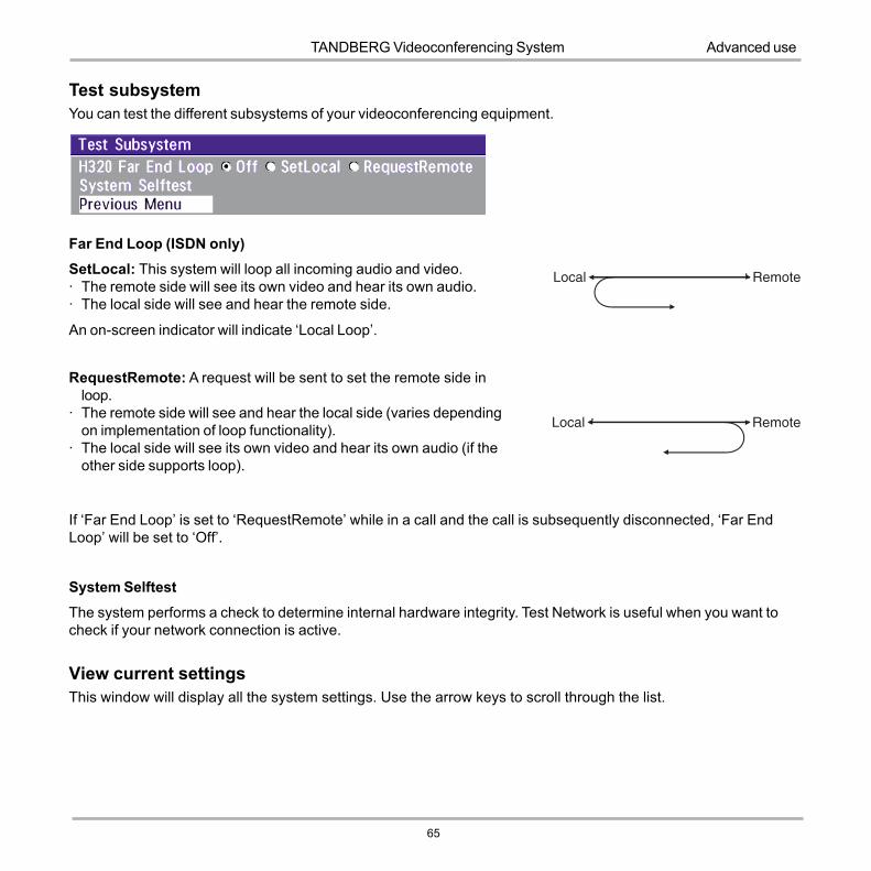
Test subsystemYou can test the different subsystems of your videoconferencing equipment.
Far End Loop (ISDN only)SetLocal: This system will loop all incoming audio and video.· The remote side will see its own video and hear its own audio.· The local side will see and hear the remote side.
An on-screen indicator will indicate �Local Loop�.
RequestRemote: A request will be sent to set the remote side inloop.
· The remote side will see and hear the local side (varies dependingon implementation of loop functionality).
· The local side will see its own video and hear its own audio (if theother side supports loop).
If �Far End Loop� is set to �RequestRemote� while in a call and the call is subsequently disconnected, �Far EndLoop� will be set to �Off�.
System SelftestThe system performs a check to determine internal hardware integrity. Test Network is useful when you want tocheck if your network connection is active.
View current settingsThis window will display all the system settings. Use the arrow keys to scroll through the list.

66
TANDBERG Videoconferencing SystemPeripherals
Interfaces
1 Video Input� 1 composite video input,
RCA connector.The system willautomatically adapt to a PALor NTSC input.
1 Audio Mini-jack� 1 stereo jack(3.5mm)
connector for headsets.
Peripheral EquipmentUsing the optional peripheral devices outlined in this chapter and the many others available, you will be able tobuild your own applications for use with the TANDBERG system, thereby better integrating the system intoyour business environment.
This chapter will explain how to connect peripheral equipment to your system. First of all however, werecommend you examine the figure below detailing the available connectors on the back of the system.

TANDBERG Videoconferencing System
67
Peripherals
Document cameraA document camera can be used for showing text, diagrams and a variety of graphical material as well as smallthree-dimensional objects. To use a document camera with your system:
� Connect the document camera to the �Video in� input on the system.
� Press DOC CAM on the remote control.doc cam
Kensington LockYou can lock your system using a Kensington Lock.This is possible by connecting the Kensington Lockto the cooling grill on the back of the system (seedrawing).
68
TANDBERG Videoconferencing SystemPeripherals
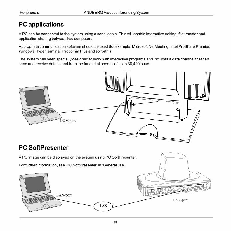
COM port
PC applicationsA PC can be connected to the system using a serial cable. This will enable interactive editing, file transfer andapplication sharing between two computers.
Appropriate communication software should be used (for example: Microsoft NetMeeting, Intel ProShare Premier,Windows HyperTerminal, Procomm Plus and so forth.)
The system has been specially designed to work with interactive programs and includes a data channel that cansend and receive data to and from the far end at speeds of up to 38,400 baud.
PC SoftPresenterA PC image can be displayed on the system using PC SoftPresenter.
For further information, see �PC SoftPresenter� in �General use�.
LANLAN-port
LAN-port

TANDBERG Videoconferencing System
69
Appendices
AppendicesAppendix 1: SecurityThe TANDBERG Videoconferencing Unit has several features both to protect from unauthorized use and systemaccess:
Access Code:
When �Access Code� is enabled, the user will be asked to enter an access code before he/she is able to make a call.
The system will verify if the entered access code is valid by checking the code with the allowed codes listed in the�access.txt� file on the ftp-server in the codec.
If no �access.txt� file is uploaded to the codec, registration of the code will be done without validation. E.g. you can enterwhatever code you want and have access to the system.
The �access.txt� file is a plain text file with one line per access code as shown below:
12341250A1B2ABC
To upload this file to the codec, follow these steps:· Open a DOS-window and go to the folder where the �access.txt� file is located.· Type ftp <IP-address of your local codec>.· �User:�, press Enter or enter IP-password.· Type �bin� and press Enter· Go to the user folder, type �cd user�.· Upload the �access.txt� file, type �put access.txt�.· Exit from ftp, type �bye�.
Menu Password:
Access to the menu system on the TANDBERG Videoconferencing unit can be controlled using password protection.This is done by using the following dataport command:
menupassword set <pin-code>. The pin-code should be maximum 5 - five digits. To erase the menu password, enteran empty pin-code.

70
TANDBERG Videoconferencing SystemAppendices
Streaming password
By setting a streaming password in the streaming menu on the TANDBERG codec, a password have to be entered onthe streaming client to be able to see the videostream from the TANDBERG Videoconferencing Unit.
IP Password
By setting a IP Password on the TANDBERG codec, all access to the system using IP (Telnet, FTP, WEB) requires apassword. This password can be enabled from telnet or dataport using the command: ippassword �<ip-password>�.
To remove this password, use the command: ippassword ��. From telnet, this is only possible by first entering thecorrect password.
Services
The different IP services on the TANDBERG codec - FTP, Telnet, HTTP, SNMP and H.323 can be disabled to preventaccess to the system. By using the commands below, the services can be independently enabled/disabled:
services <telnet/ftp/http/h323/remote-software> <enable/disable> .
In addition, the command �services <snmp> <read-only/enable/disable>� will make it possible to read SNMP messagesin addition to enable/disable SNMP.
SNMP Security alert
This function will notify any Management Application (such as TMS - TANDBERG Management Suite) if anyone tries toperform Remote Management on the TANDBERG Codec using a illegal password. The Security alert that is sent to theManagement Application will contain information about the IP address and the service (WEB, Telnet, FTP) being usedfor the attempt.
If TMS is used, email notifications or alarms about the attempt can be sent to specified persons. persons.

TANDBERG Videoconferencing System
71
Appendices
* - Optional feature
EncryptionAll TANDBERG systems support both AES* and DES encryption. By default this feature is enabled such thatwhen connecting with any other video system or MCU, a TANDBERG system will attempt to establish a secureconference using AES* or DES encryption. The TANDBERG system will attempt this for both IP and ISDNconnections. Where a remote system or MCU supports encryption, the highest common encryption algorithm willbe selected on a port by port basis.
The type and status of the encryption negotiated is indicated by padlock symbols and on-screen messages.Encryption on the TANDBERG systems is fully automatic, and provides clear security status indicators;
An open padlock indicates that encryption is being initialized, but the conference is not yet encrypted.
Single padlock indicates DES encryption.
Double padlock indicates AES encryption.
In addition to on-screen indicators the �Call Status� menu provides two information fields regarding call encryption.The first field is the �Encryption Code� which will identify either �AES� or �DES�. The second field is the �EncryptionCheck Code� and is comprised of an alphanumeric string. This string will be the same for systems on either sideof an encrypted conference. If the Check Codes do not match this would indicate that the call has been exposedto a �Man In The Middle� attack.
When a TANDBERG codec with MultiSite functionality hosts a conference, the highest possible encryptionalgorithm will be negotiated on a site by site basis. MultiSite conferences can therefore support a mix of AESand DES encrypted endpoints in the same conference.
A conference will only be as secure as its �weakest link�. Even though conference participants may havenegotiated and be running AES encryption, if just one participant has negotiated DES encryption, the AESsystem will display the single padlock symbol to advise all users of the lowest encryption mechanism currently ineffect.
All TANDBERG endpoint supporting DES encryption can upgrade to AES encryption by applying TANDBERG�sAES Encryption option. Please contact your TANDBERG representative for more information.
The standards supporting the encryption mechanisms employed by TANDBERG are: AES*, DES, H.233, H234and H.235 with extended Diffie Hellman key distribution via H.320, H.323 and Leased Line connections.

72
TANDBERG Videoconferencing SystemAppendices
Appendix 2: Using the file systemIt is possible to access a file system within the TANDBERG system by using ftp:DOS-window: ftp <IP-address of codec>, orWeb-browser: ftp:// <IP-address of codec>
Description of the different filesall.prm - all settings in the system (including directory)dir.prm - directory entriesevent.log - logs fault sitations etc.sw.pkg - the system softwareglobdir.prm - file containing up to 400 entries. These entries can not be edited from the TANDBERG Videoconferencing
system, but can be edited as a text-file.
Files accessible only by �ftp get /tmp/snapshots/xxx.jpg� or �http://<IP-address of codec>/tmp/snapshots/xxx.jpg�:main.jpg - Snapshot of current stream.local.jpg - Snapshot of selfviewfarend.jpg - Snapshot of decoded stream if point-to-point.
Description of the different foldersuser - a folder to be used for custom logos etc.remote - a folder used for software upgrade of the far end TANDBERG system
What can be done by using the file system?· software upgrade of the far end TANDBERG system (B3 or above) via ISDN· upload of custom logos
Software upgrade· Connect to the system you want to upgrade using ISDN.· Copy the software file to a folder on your harddisk.· Open a DOS-window and go to this folder.· Type ftp <IP-address of your local codec>.· Enter password: <Release Key of far end system>· Go to the remote folder, type �cd remote�· Upload the software file, type put <s0xxxxxx.pkg>· Wait until the following is shown:226 Closing data connection.5437569 bytes sent in 808.01 seconds (6.73 Kbytes/sec)ftp>
· Restart the far end codec.The far end system should now be upgraded. For further information, please contact your TANDBERG representative.

TANDBERG Videoconferencing System
73
Appendices
Custom logos
· Go to the folder where your logo is located.
LOGO MAX SIZE: 704X480 FILE-FORMAT: JPG. IF THE FILE IS TOO LARGE, NO LOGO WILL BE DISPLAYED.
· Type ftp <IP-address of your local codec>.· Go to the user folder, type �cd user�· Upload the logo, type put <startup.jpg>
The new logo will be displayed the next time you restart your system.
NOTE

74
TANDBERG Videoconferencing SystemAppendices
Appendix 3: Declaration of Conformity

TANDBERG Videoconferencing System
75
Index
IndexAAccess Code 17, 55, 68Add New Entry 22Adjusting volume 23Advanced ISDN settings 40Advanced use 34AES 56, 70Audio
outputs 65quality 35setup 53
Auto BRI Config 38
BBasics 15Battery handling 3Boot up Logo 72
CCables 10Call
making a LAN call 16making a video call 16restricted 18
Call Quality menu 35Call Settings 55Call status 63Camera
controlling 25Cause codes 62Chairman functionality 29Channel status 61Channels 18Closed Captioning 32Connecting cables 10Continuous Presence 29Control mode 59Copyright 3Correcting keying mistakes 20
DData mode 59Dataport configuration 59Declaration of Conformity 68DES 56, 70DHCP 48Diagnostics 61Dialing 16Directory
Add New Entry 22Edit Entry 22Name 22
Do not disturb 24Document camera 66Downspeeding 16
EEdit/Delete Entry 22Encryption 51, 56, 70Ending a call 20Environmental Issues 3Ethernet Speed 49Euro ISDN cause codes 62
FFar end camera control 27, 36FECC 27file system 71Floor to site # 31
GGateway 48General use 23Getting started 14Graphics
Receiving 28Sending 28
HH.264 35H.281 27
IInstallation 10Interfaces 65Introduction 7IP Address Conflict Check 63IP Password 69IP-address 48IP-subnet mask 48ISDN switch type 39ISDN-BRI Settings 38
KKensington Lock 66Key Tones 53
LLine setup 39Lock, Kensington 66Logo 72
MMaking a call 16MCU services 29Menu Access 68Menu Access Code 37, 68Menu Password 68Menu structure 8Menu system 34Microphone
on/off 23Modem mode 59Motion 35Moving camera 25MSN (Multi Subscriber Number) 41Multipoint Control Unit (MCU) 29
NNAT Address 46Natural Video 7Network Profiles 57NT1 11NTSC 65

76
TANDBERG Videoconferencing SystemIndex
PPAL 65Parallel dial 41Password 43PC 67PC applications 67PC SoftPresenter 27, 33, 67Peripherals 65Picture-in-Picture 23PIP 23Precautions 10Preset buttons 26Presets
selecting 26storing 26
Production of products 3Push-button 15
QQuality 18Quick keys 15
RRelease chair 31Release floor 30Request floor 30Restart 49Restore defaults 63Restricted call 18
SSecurity 68Selecting network 19Selecting video sources 25Services - security 69Sharpness 35Snapshots 33SNMP Agent 52
SNMP Community 52SNMP Manager 52SNMP Security alert 69SNMP Trap Host 52SNMP traps 52SoftMux 16Software Options 60Speaker on/off 23Start-up 14Still image
sending 28viewing 28
Storing presets 26Streaming 42streaming 43Streaming password 69sub-address 17Subaddress 40System configuration 12System Info 25System overview 9System start-up 14
TT.120 59Terminal ID 31Text Chat 32To adjust the volume 23To answer a call 20To call a terminal with a SUB-address 40To connect a PC to Dataport 1 59To end a call 20To enter/leave the menu system 34To select a preset 26To store the current camera position 26Trademarks 3
UUsing a SUB-address 40Utilities 36
VVideo 35
inputs 25, 65sources 25
Video call 16View
current settings 64outgoing video 23
Viewing a still image 28VNC Settings 54Voice Switched 29Volume 23
WWaste handling 3Web Snapshots 37Welcome Menu 36Welcome menu 14Wireless LAN 11Wireless LAN Settings 50WWW-interface 32
XXGA 35