taking the soil-structure interaction into account in
TRANSCRIPT
HAL Id: ineris-00961877https://hal-ineris.archives-ouvertes.fr/ineris-00961877
Submitted on 20 Mar 2014
HAL is a multi-disciplinary open accessarchive for the deposit and dissemination of sci-entific research documents, whether they are pub-lished or not. The documents may come fromteaching and research institutions in France orabroad, or from public or private research centers.
L’archive ouverte pluridisciplinaire HAL, estdestinée au dépôt et à la diffusion de documentsscientifiques de niveau recherche, publiés ou non,émanant des établissements d’enseignement et derecherche français ou étrangers, des laboratoirespublics ou privés.
Taking the soil-structure interaction into account inassessing the loading of a structure in a mining area
Olivier Deck, Marwan Al Heib, Françoise Homand
To cite this version:Olivier Deck, Marwan Al Heib, Françoise Homand. Taking the soil-structure interaction into accountin assessing the loading of a structure in a mining area. Engineering Structures, Elsevier, 2003, 25(4), pp.435-448. �10.1016/S0141-0296(02)00184-0�. �ineris-00961877�
Taking the soil-structure interaction into account in assessing the loading of a
structure in a mining subsidence area.
DECK* Olivier, AL HEIB* Marwan, HOMAND** Françoise
: Laboratoire Environnement, Géomécanique et Ouvrages (LAEGO-INPL-INERIS), Ecole des Mines de Nancy, parc deSaurupt, 54042 Nancy cedex. (Tel : (33) 03.83.58.42.89, Fax : (33) 03.83.53.38.49, [email protected]; [email protected]"* : LAEGO-INPL-INERIS, Ecole Nationale Suoèrieure de Géologie, rue du Doyen Roubault, 54500 Vandoeuvre-lè[email protected]
Abstract
Underground mining of raw materials is often the cause of ground movements at the surface. Whether planned or
accidental, such movements can cause considerable damage to structures located within the area of influence of underground
mining works. Examples are the recent subsidences that took place at the end of the 1990s in the Lorraine iron mining field. A
better understanding of how ground surface movements can be imparted to the supported structure and damage it is necessary.
Indeed, it is too often considered that damage depends only on ground strain and no account has been taken of soil-structure
interaction phenomena, which may affect considerably the structural behaviour.
The stiffness of a structure is quantified in comparison to that of the ground as regards the various movements of the
ground surface. This investigation highlights situations in which ground movements are integrally imparted to a structure.
When this is not the case, the resulting complex soil-structure interaction phenomena is analysed. For this purpose, a finite-
element software is used to generate models incorporating the ground material and a supported rigid structure. The ground
movements are broken down into two basic movements in order to highlight the impact and the relative importance of one of
theses movements : ground curvature and horizontal strain. Structural stresses are quantified for different mechanical
properties of the ground and the structure, as well as for different amplitudes of ground movement. This investigation made it
possible to devise a methodology for analyzing structures in mining subsidence areas in order to determine cases in which soil-
structure interaction phenomena must be considered. The investigation made it possible to hierarchically organize the ground
and structure parameters, the variability of which has a significant effect on the behaviour of the structure affected by mining
subsidence.
Key words: mining subsidence, soil-structure interaction, numerical methods, equivalent stiffness.
1 Introduction
The industrial need for large quantities of raw
materials at an acceptable cost has led to large
underground mines and quarries. Because of the extraction
methods, such underground mining works create
underground voids which may cause mining subsidence
phenomena, i.e. significant movements at ground surface.
This sometimes results in serious damage to structures
built in the area of influence of such movements. Mining
subsidence is planned in the case of mining methods that
incorporate the caving-in of the created cavities as work
proceeds ("caving-in" method in coal mines, for example).
On the other hand, mining subsidence is of a highly
accidental nature when it takes place over mines and
quarries that use methods based on abandoned rooms and
pillars. Indeed, in the latter case, the operator has
deliberately left in place natural or artificial pillars sized to
withstand the weight of the overburden. Recent cases of
mining subsidence that have taken place in the Lorraine
iron mining area (France) denote the hazard of such
mining works when left abandoned.
The cases of subsidence in Lorraine led public
authorities to carry investigations over the entire Lorraine
iron mining field. These investigations highlighted the
existence of about 2000 hectares of urbanised areas
undermined by abandoned works consisting of rooms and
pillars. A hierarchy of the hazard was derived : from the
risk of caving-in to the risk of structures being damaged by
planned subsidence. The second part is the topic of this
paper. Which methodology can be proposed to predict the
damage likely to affect a structure located in a hazard area,
in which considerable strata movements may occur? A
more fundamental question may be formulated: are ground
level movements imparted integrally to the structure or
does this involve soil-structure interaction phenomena
caused by significant differences in stiffness between the
ground and the structures? As long as the ground
movements are imparted to the structure integrally, a
geotechnical engineer can inform a civil engineer of the
predicted importance of such movements. The latter can
then apply these movements to the foundations of a
structure in order to assess their impact. If, on the other
hand, there is strong interaction between the ground and
the structure, neither the geotechnical engineer nor the
civi l engineer can assess the structure loading.
The ground movements describe caused by a
mining cave-in were first described. Then a method is
presented to characterise the relative stiffness of a structure
and of the ground, in terms of the surface movements
generated during a subsidence. Finally the unfavourable
case of a strong interaction between the ground and the
structure is assumed to investigate the relative effect of
different types of ground movement on the structure
behaviour.
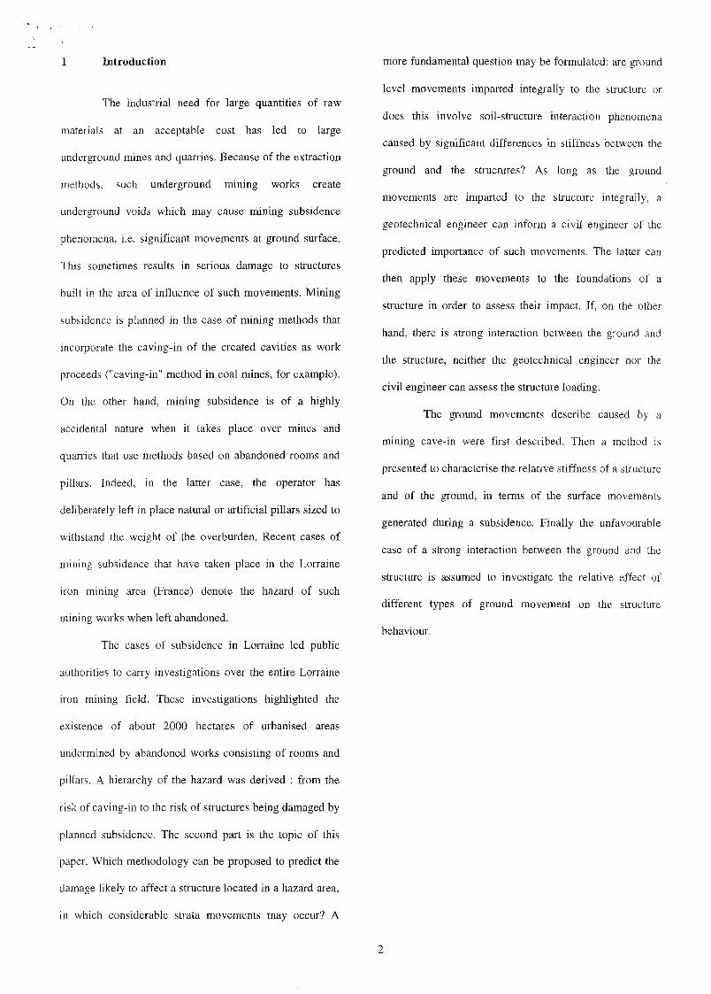
Horizontal displacement
Figure 1 : Description of ground surface movement as a
result of a mining subsidence.
2 Description of the phenomenon
Mining subsidence often produces significant
horizontal and vertical movements at the ground surface
(Figure 1). The maximum value "Sm" of the vertical
subsidence is usually considered as a characteristic of the
trough. However, the horizontal strain of the ground, its
curvature and its slope, are the three movements loading
structure and causing structural damage. The maximum
values observed for these parameters can be disastrous for
a structure if the movements are imparted integrally
(Wagner and Schumann [1]). The measurement of these
parameters entails significant difficulties either when a site
of mining subsidence is instrumented, or in a case where
cave-in has not yet taken place and prediction is regarded.
The real measurements of movement often reveal that the
vertical movement is in agreement with its theoretical
value, but the slope and the horizontal strain deviate
slightly from theory and the curvature even more so, as
shown in Figure 2 to be compared with Figure 1. The
increasing difference between theory and practice can be
readily appreciated since the slope, strain and curvature are
in reality the primary or secondary derivatives of the
displacement. The differences between the theoretical and
real displacement are then considerably amplified. When
movement predictions are involved, this difficulty entails
the presence of a large number of empirical methods for
predicting vertical displacements, a smaller number of
such methods for predicting strains and virtually no
method developed for the curvature or slope (Whittaker et
Reddish [2]).
Horizontal scale
Legend
1 : vertical subsidence2 : ground strain
-20 -i -1
-25 1 _2 1
strain subsides(mnVm) (m)
Figure 2: Example of a mining cave-in in South Africa:
vertical displacement and horizontal strain, Merwe [3],
without becoming
^~êWI#*~4 i
b) Deflected Shape à) Shearing Mode
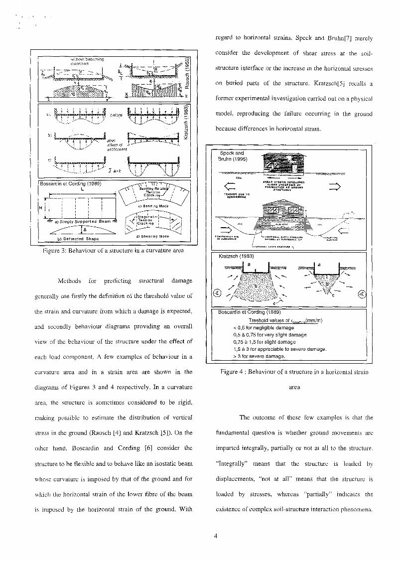
Figure 3: Behaviour of a structure in a curvature area
Methods for predicting structural damage
generally use firstly the definition of the threshold value of
the strain and curvature from which a damage is expected,
and secondly behaviour diagrams providing an overall
view of the behaviour of the structure under the effect of
each load component. A few examples of behaviour in a
curvature area and in a strain area are shown in the
diagrams of Figures 3 and 4 respectively. In a curvature
area, the structure is sometimes considered to be rigid,
making possible to estimate the distribution of vertical
stress in the ground (Rausch [4] and Kratzsch [5]). On the
other hand, Boscardin and Cording [6] consider the
structure to be flexible and to behave like an isostatic beam
whose curvature is imposed by that of the ground and for
which the horizontal strain of the lower fibre of the beam
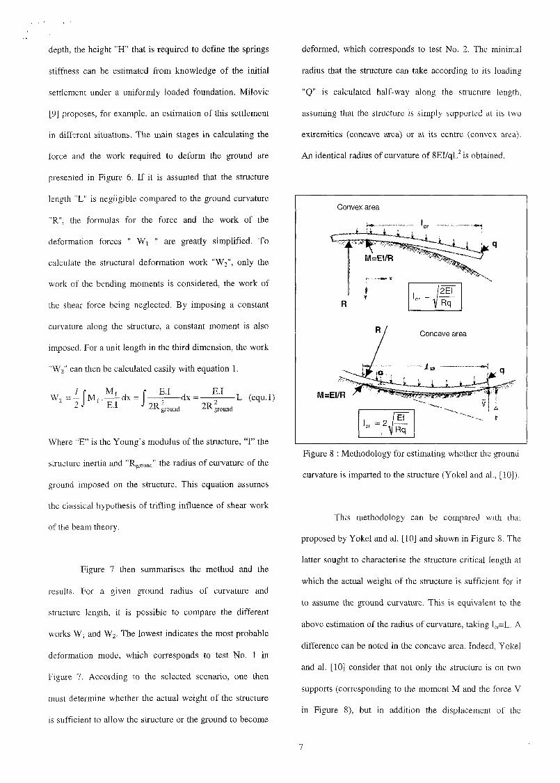
is imposed by the horizontal strain of the ground. With
regard to horizontal strains, Speck and Bruhn[7] merely
consider the development of shear stress at the soil-
structure interface or the increase in the horizontal stresses
on buried parts of the structure. Kratzsch[5] recalls a
former experimental investigation carried out on a physical
model, reproducing the failure occurring in the ground
because differences in horizontal strain.
Speck andBruhn(1995)
= >
(•—amaiMi. EARTH pncsiun e a-
Kratzsch (1983)a
_L
Boscardin et Cording (1989)
Treshold values of £5tmcture(mm/m)< 0,5 for negligible damage0,5 à 0,75 for very slight damage0,75 à 1,5 for slight damage1,5 à 3 for appreciable to severe damage.> 3 for severe damage.
Figure 4 : Behaviour of a structure in a horizontal strain
area
The outcome of these few examples is that the
fundamental question is whether ground movements are
imparted integrally, partially or not at all to the structure.
"Integrally" means that the structure is loaded by
displacements, "not at all" means that the structure is
loaded by stresses, whereas "partially" indicates the
existence of complex soil-structure interaction phenomena.

3 Characterisation of the relative stiffness of a
structure compared to the ground
The investigation of soil-structure interaction
require a clear definition of stiffness. Two stiffness
parameters are involved : a first stiffness parameter
characterises the behaviour of the structure as compared
with that of the ground as regards surface curvature ; a
second parameter characterises the compared behaviour as
regards the ground horizontal strain. We propose to
characterise the ground stiffness and the structure stiffness
as regards these two parameters of ground movement in
order to determine the situations in which one or the other
of these parameters is integrally transmitted to the
structure.
(initial shape of theground is curved)
Contact between theground and the structure
Only the ground is deformed
Only the structure isdeformed
The ground and thestructure are deformed
The structure isdetached
(insufficient weight)
Figure 5 : Various possible behaviours of a structure in a
concave curvature area
3.1 Estimation of the stiffnesses as regards
ground curvature
The reasoning is based on calculating the
mechanical energy required either to impose the ground
curvature on a structure, or to impose a structure
horizontally on an initiall y curved ground. The scenario
calling for the lowest energy is considered the more likely.
Figure 5 provides schematic illustrations of the possible
scenarios for a concave area.

Es : ground Young's modulusL : structure length
: ground radius of curvature: stiffness of springs (Winkler's model)
v(9)=R d.(l-cos6)dk=K.dxdx=R.cos9.dedF= v(8).dkdW,= l/2.v(9).dF
Figure 6 : Calculation of force and work required to deform the ground.
TEST n°
W2 « W, - > Rstmcture — Aground
W2 «W, => Rstruc,ure > Rground (interaction)
W 2 » W j => Rstructl lre —> °° (horizontal structure )
Work «W2» to impose the ground curvature on the structureconcave area : W2 = E.I.L/2R2
groimd
convex area : W2 = E.I.L/2R2ground
Workl to deform the ground :concave area : W, = K.L 5/(640. R2
groimd)convex area : Wj = K.L 5/(240. R2
ground)
Structure weigth «P» : P=q.L
Force to cause ground contact « F »concave area : F = K.L3/48R2
ai.ound
convex area : F = K.L 3/24R2ground
_rP <F => Structure overhanginP >F => Perfect contact ground-structure
TEST nc2
Ground radius of curvature «Rground»
Structure minimumRmi]1 = 8.E.I/(q.L2)Structure minimum radius «Rmin
>:> :TEST n°2•̂terrai n "̂ *\ni n ~'> "structure ^ Rground
(Structure overhanging)R > R => R — R
terrain — r vmin structure -^terrain(Perfect contact ground-structure )
E : Young's modulus of thestructureI : equivalent structureinertiaL : structure lengthq : unit structure weigthK : stiffness of springs(Winkler 's model)
Aground ' ër o u nd radius ofcurvature
Figure 7 : Methodology for estimating whether the ground curvature is imparted to the structure.
A detailed development of the calculation is done
for the case of a concave area. A similar approach can be
adopted for the case of a convex area. The ground is
modelled by spring elements (Figure 6). adopting the
Winkler model. The latter assumes that the spring
elements do not interact between each other. Each spring is
thus characterised simply by its stiffness "K" . A number of
other more complex models (Henry [8]) have been
developed, which could be adopted if necessary. The
difficult y with such a model is to select a value for the
stiffness "K" . If it is assumed that there is a rigid
substratum at a depth "h", it is possible to estimate the
stiffness as a function of "h" and the ground mechanical
properties (Figure 6). If there is no rigid substratum at
depth, the height "H" that is required to define the springs
stiffness can be estimated from knowledge of the initial
settlement under a uniformly loaded foundation. Milovi c
[9] proposes, for example, an estimation of this settlement
in different situations. The main stages in calculating the
force and the work required to deform the ground are
presented in Figure 6. If it is assumed that the structure
length "L" is negligible compared to the ground curvature
"R", the formulas for the force and the work of the
deformation forces " Wj " are greatly simplified. To
calculate the structural deformation work "W2", only the
work of the bending moments is considered, the work of
the shear force being neglected. By imposing a constant
curvature along the structure, a constant moment is also
imposed. For a unit length in the third dimension, the work
"W2" can then be calculated easily with equation 1.
E.I 9R/->x 2i-ound
ground
(equ.l)
Where "E" is the Young's modulus of the structure, "I " the
structure inertia and "Rground" the radius of curvature of the
ground imposed on the structure. This equation assumes
the classical hypothesis of triflin g influence of shear work
of the beam theory.
Figure 7 then summarises the method and the
results. For a given ground radius of curvature and
structure length, it is possible to compare the different
works W] and W2. The lowest indicates the most probable
deformation mode, which corresponds to test No. 1 in
Figure 7. According to the selected scenario, one then
must determine whether the actual weight of the structure
is sufficient to allow the structure or the ground to become
deformed, which corresponds to test No. 2. The minimal
radius that the structure can take according to its loading
"Q" is calculated half-way along the structure length,
assuming that the structure is simply supported at its two
extremities (concave area) or at its centre (convex area).
An identical radius of curvature of 8EI/qL2 is obtained.
Concave area
M=EI/R
Figure 8 : Methodology for estimating whether the ground
curvature is imparted to the structure (Yokel and al., [10]).
This methodology can be compared with that
proposed by Yokel and al. [10] and shown in Figure 8. The
latter sought to characterise the structure critical length at
which the actual weight of the structure is sufficient for it
to assume the ground curvature. This is equivalent to the
above estimation of the radius of curvature, taking lcr=L. A
difference can be noted in the concave area. Indeed, Yokel
and al. [10] consider that not only the structure is on two
supports (corresponding to the moment M and the force V
in Figure 8), but in addition the displacement of the
7
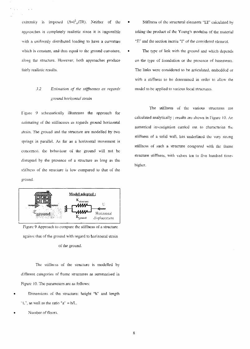
extremity is imposed (A=l" cr/2R). Neither of the
approaches is completely realistic since it is impossible
with a uniformly distributed loading to have a curvature
which is constant, and thus equal to the ground curvature,
along the structure. However, both approaches produce
fairly realistic results.
3.2 Estimation of the stiffnesses as regards
ground horizontal strain
Figure 9 schematically illustrates the approach for
estimating of the stiffnesses as regards ground horizontal
strain. The ground and the structure are modelled by two
springs in parallel. As far as a horizontal movement is
concerned, the behaviour of the ground wil l not be
disrupted by the presence of a structure as long as the
stiffness of the structure is low compared to that of the
ground.
Model adopted :
-ground displacement
Figure 9 Approach to compare the stiffness of a structure
against that of the ground with regard to horizontal strain
of the ground.
Stiffness of the structural elements "El" calculated by
taking the product of the Young's modulus of the material
"E" and the section inertia "I " of the considered element.
The type of link with the ground and which depends
on the type of foundation or the presence of basements.
The links were considered to be articulated, embedded or
with a stiffness to be determined in order to allow the
model to be applied to various local structures.
The stiffness of the various structures are
calculated analytically ; results are shown in Figure 10. An
numerical investigation carried out to characterise the
stiffness of a solid wall, has underlined the very strong
stiffness of such a structure compared with the frame
structure stiffness, with values ten to five hundred times
higher.
The stiffness of the structure is modelled by
different categories of frame structures as summarised in
Figure 10. The parameters are as follows:
Dimensions of the structure: height "h" and length
"L" , as well as the ratio "a" = h/L.
Number of floors.
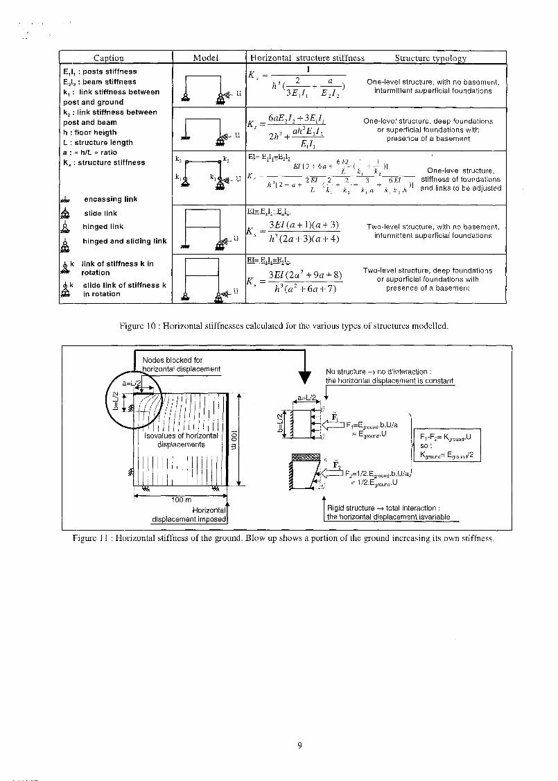
Caption Model Horizontal structure stiffness Structure typologyE1I1 : post s stiffnes sE2I2 : beam stiffnes sk, : link stiffnes s betweenpost and groundk2 : link stiffnes s betweenpost and beamh : floo r heigt hL : structur e lengt ha : « h/L » ratioK. : structur e stiffnes s
dm encassin g link
slid e link
hinge d link
. hinge d and slidin g link
, k link of stiffnes s k in* rotatio n>k slid e link of stiffnes s k\ in rotatio n
K, = 1
h\^E2I2
One-level structure, with no basement,intermittent superficial foundations
U
R =6aE2I2 + 3ElI l
o,,3 , ah3E2I2
One-level structure, deep foundationsor superficial foundations with
presence of a basement
_,k2hi— b t l i —li-ilo
K , =£/[3 + 6a + - ^ - ( — +— );
One-level structure,
L k.
3 6 El st i f fness of foundat ions
k,.a k,.k2.h a n d i i n k s t 0 b e adjusted
K. = Two-level structure, with no basement,intermittent superficial foundations
EI= E1I1=]
K. =Two-level structure, deep foundations
or superficial foundations withpresence of a basement
Figure 10 : Horizontal stiffnesses calculated for the various types of structures modelled.
Nodes blocked forhorizontal displacement
Isovalues of horizontaldisplacements
100 m IHorizontalT
displacement imposed]
i No structure -> no d'interaction :the horizontal displacement is constant
AF,
F,-F2=> s o :
Aground'
Kf
= E
rounc
groun
.u~ Aground'^
F2=1/2.Eground.b.U/aJ= 1/2.Eground.U
Rigid structure -» total interaction :the horizontal displacement isvariable
Figure 11 : Horizontal stiffness of the ground. Blow up shows a portion of the ground increasing its own stiffness.
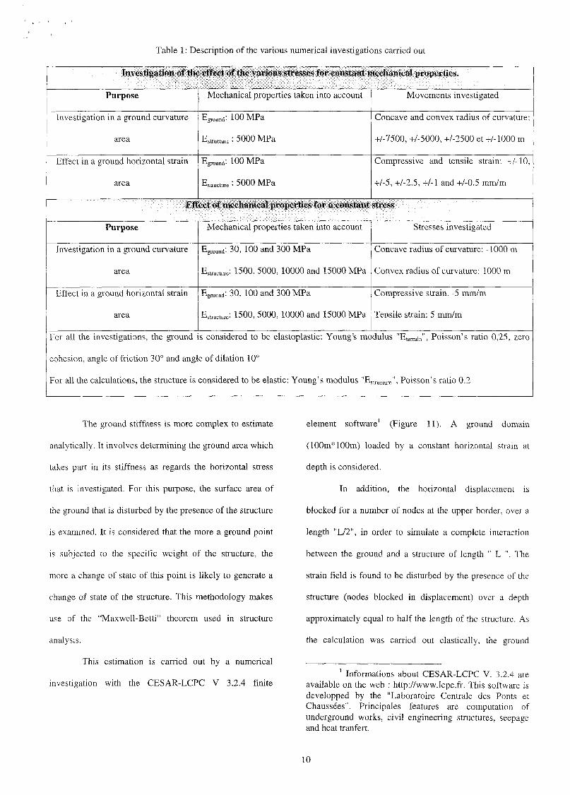
Table 1 : Description of the various numerical investigations carried out
Investigation of the effect of the various stresses for constant mechanical properties.
Purpose
Investigation in a ground curvature
area
Effect in a ground horizontal strain
area
Mechanical properties taken into account
Eground: 100 M Pa
Estructure : 5000 M Pa
E ^ : 100 MPa
Estructm-e : 5 0 00 M Pa
Movements investigated
Concave and convex radius of curvature:
+/-7500, +/-5000, +/-2500 et +/-1000 m
Compressive and tensile strain: +/-10,
+/-5, +/-2.5, +1-1 and +/-0.5 mm/m
Effect of mechanical properties for a constant stress
Purpose
Investigation in a ground curvature
area
Effect in a ground horizontal strain
area
Mechanical properties taken into account
Eground: 30, 100 and 300 MPa
E ^ u r e: 1500, 5000, 10000 and 15000 MPa
Eground: 30, 100 and 300 MPa
Estructure: 1500, 5000, 10000 and 15000 MPa
Stresses investigated
Concave radius of curvature: -1000 m
Convex radius of curvature: 1000 m
Compressive strain. -5 mm/m
Tensile strain: 5 mm/m
For all the investigations, the ground is considered to be elastoplastic: Young's modulus "Eterrain" , Poisson's ratio 0,25, zero
cohesion, angle of friction 30° and angle of dilation 10°
For all the calculations, the structure is considered to be elastic: Young's modulus "Estructure", Poisson's ratio 0.2
The ground stiffness is more complex to estimate
analytically. It involves determining the ground area which
takes part in its stiffness as regards the horizontal stress
that is investigated. For this purpose, the surface area of
the ground that is disturbed by the presence of the structure
is examined. It is considered that the more a ground point
is subjected to the specific weight of the structure, the
more a change of state of this point is likely to generate a
change of state of the structure. This methodology makes
use of the "Maxwell-Betti" theorem used in structure
analysis.
This estimation is carried out by a numerical
investigation with the CESAR-LCPC V 3.2.4 finite
element software1 (Figure 11). A ground domain
(100m* 100m) loaded by a constant horizontal strain at
depth is considered.
In addition, the horizontal displacement is
blocked for a number of nodes at the upper border, over a
length "L/2" , in order to simulate a complete interaction
between the ground and a structure of length " L ". The
strain field is found to be disturbed by the presence of the
structure (nodes blocked in displacement) over a depth
approximately equal to half the length of the structure. As
the calculation was carried out elastically, the ground
1 Informations about CESAR-LCPC V. 3.2.4 areavailable on the web : http://www.lcpc.fr. This software isdevelopped by the "Laboratoire Centrale des Ponts etChaussées". Principales features are computation ofunderground works, civil engineering structures, seepageand heat tranfert.
10
stiffness was presumably overestimated. It can thus be
assumed that the portion of the ground which takes part in
stressing the structure is distributed, at most, over a depth
approximately equal to the structure length. More
specifically, the result of the numerical investigation
highlights a fairly regular variation in the horizontal
displacements under the structure. It appears that the
contribution of the ground to its own stiffness increases
with the proximity to the ground surface. This results in a
ground stiffness which can be estimated to half its
Young's modulus (Figure 11).
As the real phenomenon is three-dimensional, a
unit extension must be considered to compare the two
elements. The stiffnesses of the structural elements "El"
must thus be homogenised for a unit extension of the
structure. If the stiffness of the structure is low as
compared to that of the ground (figures 10 and 11), the
structure is considered to be flexible and the horizontal
movement of the ground is integrally transmitted to the
structure. If, on the other hand, the stiffness of the
structure is high as compared to that of the ground, the
structure is considered to be rigid. The ground movement
is then necessarily strongly disrupted by the presence of
the structure, and this calls for a detailed investigation of
the soil-structure interaction phenomena. For this purpose,
the following section investigates the behaviour of a rigid
structure of the load-bearing-wall type, with regard to
mining subsidence.
4 Stress-strain investigation
This investigation is intended to highlight the
overall behaviour of a solid-wall type structure, i.e.
structure that is very rigid as compared to the ground. For
this purpose, a set of numerical simulations was carried out
in order to investigate the behaviour of a structure with
regard to each basic loading components: horizontal strain
and curvature. The effect of the slope was not investigated
since the slope, as a rigid body movement of the structure,
produces very littl e stress in the structure.
The finite element software CESAR-LCPC was
used with six-node triangular elements, eight-node
quadrangular elements and six-node interface elements.
The latter elements make it possible to take into account a
friction type behaviour as well as an interface separation.
In all of the simulations, the ground behaviour was
considered to be elastoplastic with a Mohr-Coulomb
failure criteria ; the structure was considered elastic. The
results shown below correspond to the structure and the
soil-structure interaction before structure damage. This
choice is justified considering the very high mechanical
strength of the structure in comparison with that of the
ground.
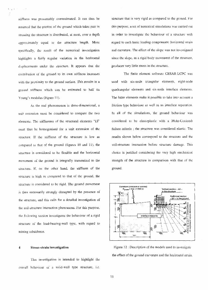
Curvature (concave or convex)"around = 0 tO +/-7500 m
Figure 12 : Description of the models used to investigate
the effect of the ground curvature and the horizontal strain.
11
Two sets of models were produced, and are
shown in Figure 12. The first model is used to investigate
the effect of a curvature of the ground. The second model
considers the effect of a horizontal strain of the ground.
The two models represent a ground domain measuring 15
m by 15 m, with a solid structure on its surface. The left
border is a symmetry axis, and the calculations were
carried out for plane strains. In order to simulate the effect
of the ground curvature, the ground surface is modelled
with a surface curvature (concave or convex curve) on
which a perfectly horizontal structure is located. The
interface elements between the structure and the ground
are initially disconnected, except at the extremities of the
structure for the concave area and at the centre for the
convex area. The ground was consolidated under its own
weight, then loaded by the weight of the structure. The
results were analysed by considering stress components in
the ground and in the structure, in particular along selected
sections as shown in Figure 12. A particular attention was
paid to the localisation of the failure points in the model.
In order to simulate the effect of the horizontal
strain of the ground (tension or compression), an initially
horizontal ground surface is consolidated under its own
weight, then loaded by that of the structure and finally
deformed by imposing a uniform horizontal displacement
on the right border of the model. Different values of
curvature and strain were investigated as well as different
values of the mechanical properties of the ground and of
the structure. The effect of each component of ground
movement (curvature and strain) was first investigated for
fixed values of mechanical properties ; then the influence a
variation of these properties was analysed (Table 1). A
description of all the investigations is first presented before
results are discussed.
• Reference investigation: the consolidation of the
ground under its own weight and the weight of the
structure is investigated, with no additional loading.
• Investigation of the ground curvature: the effect of a
concave and convex curvature of the ground with a radius
of +/- 1000 m is investigated.
• Investigation of the horizontal strain of the ground: the
effect of a tensile and compressive strain with an intensity
of+/- 5 mm/m is investigated.
• Ground properties (elastoplastic): Young's modulus
"Eground" 100 MPa, Poisson's ratio 0.25, cohesion 0, friction
angle 30° and dilation angle 10°.
• Structure properties (elastic): Young's modulus of the
ground "Estracture" is 5000 MPa and its Poisson's ratio is 0.2.
4.1 Curvature analysis
The effect of the ground curvature on a structure
is easy to understand as illustrated in Figure 3 that shows
different diagrams of the operating mechanism in a
curvature area. A concentration of vertical stresses at the
ends of the structure is expected in a concave area and at
the centre in the convex area in the centre. The schematic
diagrams of Figure 3 can be compared to the results
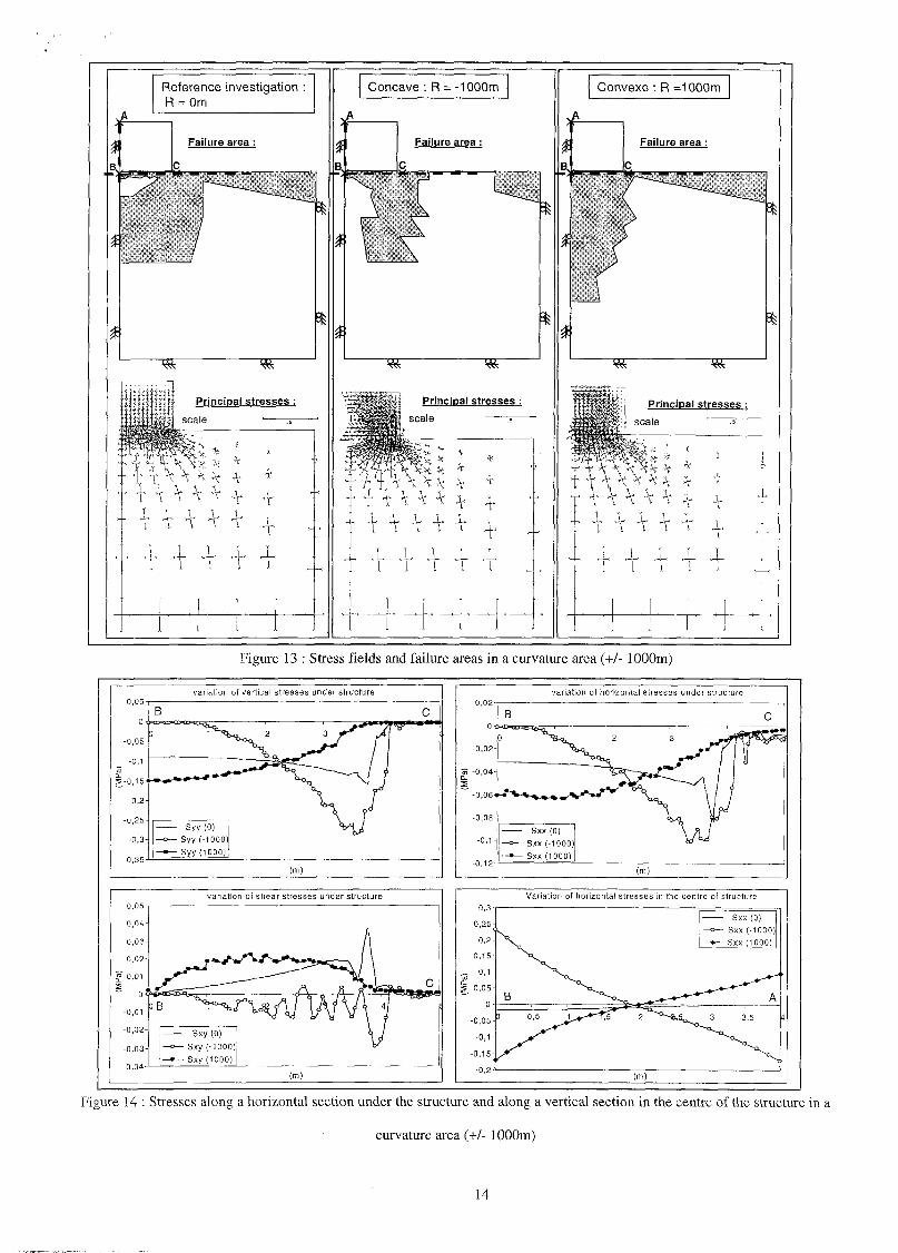
obtained with numerical modellings, Figure 13 and 14.
These figures respectively show the results in the entire
model and along two sections shown in figure 12 and
located horizontally at a depth of 15 cm in the ground
(section "BC") and vertically in the centre of the structure
(section "AB") . Interesting aspects of these results are
discussed below.
12
Failure area differs from the failure area obtained in
the reference investigation. The plastic points are
concentrated perpendicularly to the areas on which the
structure rests preferentially. These points are thus
deduced from the high values of the vertical stress. Failure
which occur at the right hand edge of the model is the
consequence of the mesh size in these area and of the zero
cohesion of the ground.
The representation of the principal stresses highlights
remarkably the stress redistribution in the ground. Stresses
observed in the structure reflect a bending movement,
consistent with the ground curvature. However, the
structure curvature is never as high as the ground
curvature. The structure stiffness is such that it retains a
horizontal geometry.
The analysis of the vertical stress under the structure
shows that the disturbances are greater for a concave
curvature than for a convex curvature. The vertical stress
in the ground, underneath the area on which the structure
rests preferentially, increase by 60% in convex areas and
by about 100% in concave areas. In addition, a structure is
more likely to be found partially disconnected from the
ground in the concave area than in the convex area. This
support the intuitive approach adopted by Kratzsch [5],
who suggested that the structure remains horizontal as
compared to that of Boscardin and Cording [6], who
suggested that the curvature of the ground is transmitted to
the structure. It appears that the separation is actually not
related to the bending flexibilit y of the structure but
instead to the vertical flexibilit y of the ground.
The horizontal stress increases proportionally to the
vertical stress. This increase is due to the lateral behaviour
of the ground under a vertical load (Poisson's ratio),
tempered by the failure criteria.
The shear stress under the structure reveals a
limitation of our modelling. Indeed, the solving process for
elastoplastic computation lead to be in search of
convergence the calculations. In spite of a satisfactory
convergence in the concave area, a strange variation is
observed of the shear stress under the structure. The only
average value appears consistent in spite of other
variations. This phenomenon is indicative of a numerical
problem. Moreover, an observation of the iso-values of
plastic strains has highlighted high plastic strain under the
structure, up to 4.5%, very locally in a concave area and
1.4% in a convex area.
• The state of stress in the structure is consistent with all
of the previous results. Tensile stress appears in the lower
edge (0.1 MPa) in convex areas and in the upper edge in
concave areas (0.24 MPa).
13
Reference investigation :R = Om
Failur e area :
Principa l stresse s :scale • ^-
Concave : R = -1000m
Failur e area :
Principa l stresse s :scale • ^~
Convexe :R =1000m
Figure 13 : Stress fields and failure areas in a curvature area (+/- 1000m)
variation of vertical stresses under structure
Syy (0)• Syy (-1000)|- Syy (1000)
(m)
variation of shear stresses under structure
variation of horizontal stresses under structure
Variation of horizontal stresses in the centre of structure
Figure 14 : Stresses along a horizontal section under the structure and along a vertical section in the centre of the structure in a
curvature area (+/- 1000m)
14
Reference investigation :
Failure area :
»*
Principal stresses :
11 Scale ' j
Compressive strain :
£=-5mm/m
Failure area :
Principal stresses :
Scale • —
Extensive strain :
£=5mm/m
Failure area :
U=5cm
*&
Principal stresses :
Scale
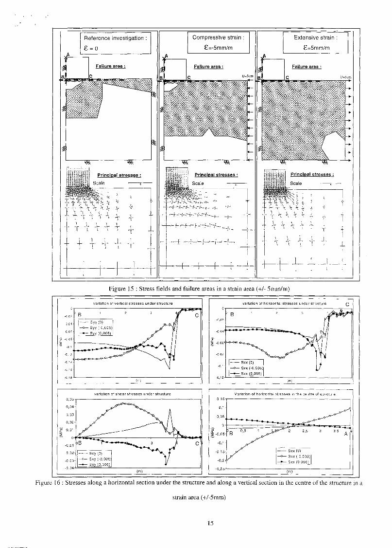
Figure 15 : Stress fields and failure areas in a strain area (+/- 5mm/m)
-0,02
-0.04
-0,06 •
1î -0,08'Q.
" -o, i •
-0,12 •
-0,14 •
-0,16
1 B
—o-
—•-
>-©-CxC
variation of vertica
1 2
- Syy (0)— Syy (-0,005)- Syy (0,005)
stresses under structure
3 4^?
m
y\
(m)
•»-*ft=*- lC
-0,02-
-0,04'
| -0,06 (
-0,08-
-0,1 •
' B
•-o-o œ
— o -
—•—
variation of horizonta
1 2
- Sxx (0)- Sxx (-0,005)- Sxx (0,005)
stress
S"
(m)
3S under structure
y,flC
0,04-
0,03-
0,02-
£ 0,01-5— o<
-0,01-
-0,02-
-0,03-
3B
—c
—«
variation of shear stresses under structure
— Sxy(O) X +•— Sxy (-0,005) 1 /•— Sxy (0,005) *
(m)
c
Variation of horizontal stresses in the centre of structure
Figure 16 : Stresses along a horizontal section under the structure and along a vertical section in the centre of the structure in a
strain area (+/-5mm)
15
4.2 Strain analysis
In the same way as for curvature, the effect of a
horizontal strain of the ground on a structure has often
been grasped qualitatively (Figure 4). The main idea
adopted so far has been to assume that the horizontal strain
of the ground only produces a uniform horizontal strain in
the structure. The investigation presented here provides a
visualisation and a quantitative analysis of the behaviour
of a structure under such a load. The results are shown in
Figure 15 and 16.
• The failure points in the model vary differently
according to the strain direction. A generalised failure in
the model can be observed in the tensile area, which can be
readily understood given that the strain tends to decrease
the horizontal minor stress whereas the vertical major
stress remains unchanged. In compression areas, however,
a confined area is observed under the structure, similarly to
that obtained with the reference investigation (structure
resting on a flat soil without strain) and which is similar to
the cone of ground which shape is preserved under a
vertically loaded foundation.
• The stress field in the model shows that a compressive
strain generates a stress concentration in the ground under
the centre of the structure as well as bending stresses in the
structure. In a tensile area, however, the stress field seems
to be relatively littl e modified in the ground and in the
structure.
• The variation in vertical stress under the structure
provides a good representation of the overall behaviour.
The compressive strain leads the structure to rest
preferentially on its middle section. The stress increase is
then about 40%, i.e. an value comparable to that observed
for the curvature. In tensile areas, however, a re-
homogenisation of the vertical stress is observed under the
structure.
• The horizontal stress in the ground increases only
slightly in tensile areas. In compressive areas, however, a
penetration of the horizontal stress under the structure can
be observed and no increase in these stresses is observed
towards the outside of the structure. Indeed, the presence
of the free surface does not allow a significant increase in
the horizontal stress as the vertical stress is very low. It is
of interest to compare this result against one of the
remedial actions that is proposed to minimise the effect of
the strain: the digging of trenches around the periphery of
the structure is often mentioned as a technical solution.
The stress on the ground surface proves to be low on
account of the adopted failure criterion (Mohr-Coulomb).
Therefore, such a solution does not completely cancel the
effect of the strain.
A shearing phenomenon appears naturally under the
structure. Contrary to what is often assumed (Kratzsch,
[5], the value of the shear stress is not constant. In a
compressive area, the variation in the shear stresses is
more complex than in a tensile area. This phenomenon is
associated with the distribution of the vertical stress which
varies significantly along the structure.
• The structure is much less affected by the strain
imposed by the ground than if such strain is imparted
integrally. Indeed, a strain of +/- 0.005 mm/m has the
effect of a horizontal stress of 25 MPa in the structure.
Instead of such a value, the compressive area causes a
compressive stress of -0.2 MPa in the lower edge and a
tensile stress of 0.1 MPa in the upper edge ; the structure is
16
thus bent. To a lesser extent, the same phenomenon is
observed in a tensile area since the latter tensile horizontal
stain generates tensile stresses of 0.04 MPa in the lower
edge and -0.02 MPa in the upper edge. The compressive
stress distributed in the ground and the direction of the
shear stress are both responsible for the bending that is
observed.
4.3 Sensitivity analysis
A sensitivity analysis was carried out to evaluate
the effect of the mechanical properties of the ground and
of the structure on the results discussed above. Whole of
the investigation are presented in Table 1 and the main
observations are discussed below:
• Al l of the calculations showed that the mechanical
properties of the structure have no effect on the results. In
reality the structure is much more rigid than the ground in
all of the calculations: The Young's modulus of the
structure is at least five times greater than that of the
ground, and the calculation for plane strains leads to an
overestimation of the structure stiffness.
• An increase of the ground Young's modulus leads to
an increase of the phenomena described above. In a curved
area, it can be seen that the disconnected length of the
structure increases with a higher modulus of elasticity of
the ground (100 MPa) and disappears completely with a
lower modulus (30 MPa).
• The horizontal stress in the structure increases and
show a bending moment which increases as the ground
stiffness increases.
Irrespective of the selected mechanical properties, the
stress state in the ground and in the structure is more
disrupted in a concave area than in a convex area.
An increase of the plastic strain value is observed in
the model with increasing of the ground modulus of
elasticity. In particular, the analysis of a compressive strain
with a ground Young's modulus of 300 MPa gives clearly
inconsistent results. The model thus produced does not
make it possible to describe the behaviour of a ground
domain subject to large plastic strain.
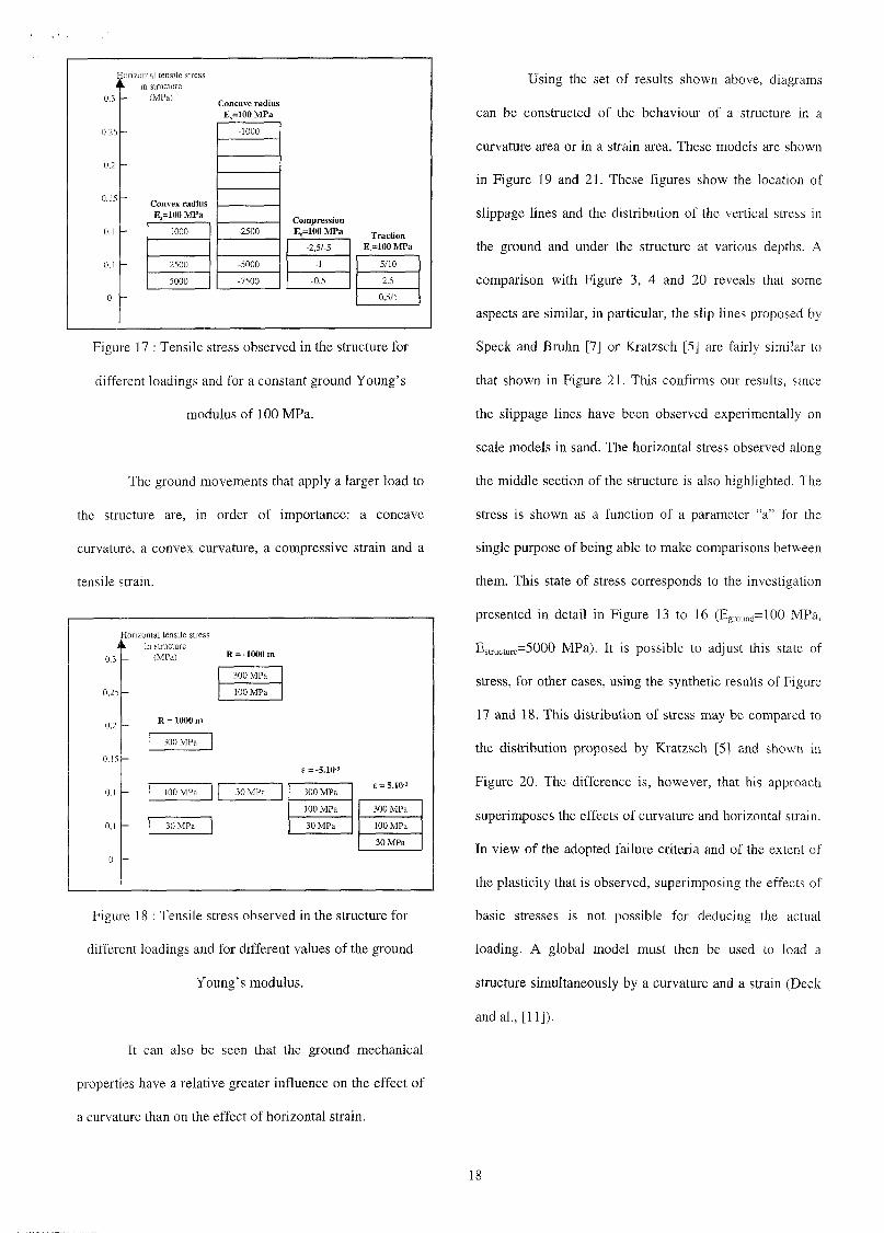
An overall picture of the numerous quantitative
results that was obtained is provided by series of value of
tensile stress in the structure observed in the different
models. Figure 17 and 18 provide a rapid comparison of
each investigation. It can thus be seen in Figure 17 that for
a ground modulus of elasticity of 100 MPa, a radius of
curvature of +5000 or -7500 m generates the same tensile
stresses as a strain o f -0 .5 or +2.5 mm/m. Figure 18 allows
this same comparison to be made when the ground's
Young's modulus varies. As an example, a radius of
curvature of 1000m of a ground characterised by a
Young's modulus of 30 MPa, generates the same stress in
the structure as a extension strain of 5 mm/m in a ground
with a modulus of 100 MPa.
17
0,3
Horizontal tensile stressin structure
(MPa)
0,25
0,2
0,15
Concave radiusE =100 MPa
Convex radiusE,=100 MPa
1000
2500
5000
-1000
-2500
-5000
-7500
CompressionE,=100 MPa
-2,5/-5
-1
-0,5
TractionE,=100 MPa
5/10
2,5
0,5/1
Figure 17 : Tensile stress observed in the structure for
different loadings and for a constant ground Young's
modulus of 100 MPa.
The ground movements that apply a larger load to
the structure are, in order of importance: a concave
curvature, a convex curvature, a compressive strain and a
tensile strain.
0.3
Horizontal tensile stressin structure
(MPa)
0,25
0,2
0.15
R = -1000 m
300 MPa
100 MPa
300 MPa
100 MPa
30 MPa
30 MPa
6 = -5.10-3
300 MPa
100 MPa
30 MPa
t = 5.10-3
300 MPa
100 MPa
30 MPa
Figure 18 : Tensile stress observed in the structure for
different loadings and for different values of the ground
Young's modulus.
It can also be seen that the ground mechanical
properties have a relative greater influence on the effect of
a curvature than on the effect of horizontal strain.
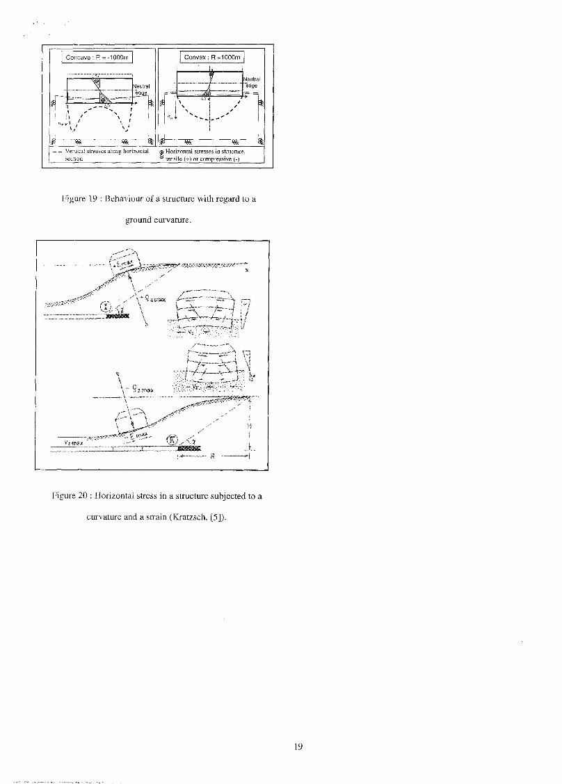
Using the set of results shown above, diagrams
can be constructed of the behaviour of a structure in a
curvature area or in a strain area. These models are shown
in Figure 19 and 21. These figures show the location of
slippage lines and the distribution of the vertical stress in
the ground and under the structure at various depths. A
comparison with Figure 3, 4 and 20 reveals that some
aspects are similar, in particular, the slip lines proposed by
Speck and Bruhn [7] or Kratzsch [5] are fairly similar to
that shown in Figure 21. This confirms our results, since
the slippage lines have been observed experimentally on
scale models in sand. The horizontal stress observed along
the middle section of the structure is also highlighted. The
stress is shown as a function of a parameter "a" for the
single purpose of being able to make comparisons between
them. This state of stress corresponds to the investigation
presented in detail in Figure 13 to 16 (Eground=100 MPa,
Esnucture=5000 MPa). It is possible to adjust this state of
stress, for other cases, using the synthetic results of Figure
17 and 18. This distribution of stress may be compared to
the distribution proposed by Kratzsch [5] and shown in
Figure 20. The difference is, however, that his approach
superimposes the effects of curvature and horizontal strain.
In view of the adopted failure criteria and of the extent of
the plasticity that is observed, superimposing the effects of
basic stresses is not possible for deducing the actual
loading. A global model must then be used to load a
structure simultaneously by a curvature and a strain (Deck
andal., [11]).
18
Concave : R = -1000m Convex :
- -
= ™ /à
R
....
F
=1000m
- - —i
. „ • =
Vertical stresses along horizontal © Horizontal stresses in structure,section ® tensile (+) or compressive (-)
Figure 19 : Behaviour of a structure with regard to a
ground curvature.
Figure 20 : Horizontal stress in a structure subjected to a
curvature and a strain (Kratzsch, [5]).
19
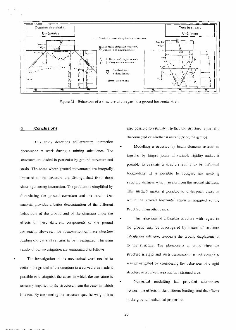
Vertical stresses along horizontal sections
© Horizontal stresses in structure.® tensile (+) or compressive (-)
Horizontal displacementsalong vertical sections
i Confined areawith no failure
1—T Failure line
Tensile strain :
£=5mm/m
Figure 21 : Behaviour of a structure with regard to a ground horizontal strain.
Conclusions
This study describes soil-structure interaction
phenomena at work during a mining subsidence. The
structures are loaded in particular by ground curvature and
strain. The cases where ground movements are integrally
imparted to the structure are distinguished from those
showing a strong interaction. The problem is simplified by
dissociating the ground curvature and the strain. Our
analysis provides a better determination of the different
behaviours of the ground and of the structure under the
effects of these different components of the ground
movement. However, the combination of these structure
loading sources still remains to be investigated. The main
results of our investigation are summarised as follows:
The investigation of the mechanical work needed to
deform the ground of the structure in a curved area made it
possible to distinguish the cases in which the curvature is
certainly imparted to the structure, from the cases in which
it is not. By considering the structure specific weight, it is
also possible to estimate whether the structure is partially
disconnected or whether it rests fully on the ground.
Modelling a structure by beam elements assembled
together by hinged joints of variable rigidity makes it
possible to evaluate a structure ability to be deformed
horizontally. It is possible to compare the resulting
structure stiffness which results from the ground stiffness.
This method makes it possible to distinguish cases in
which the ground horizontal strain is imparted to the
structure, from other cases.
The behaviour of a flexible structure with regard to
the ground may be investigated by means of structure
calculation software, imposing the ground displacements
to the structure. The phenomena at work when the
structure is rigid and such transmission is not complete,
was investigated by considering the behaviour of a rigid
structure in a curved area and in a strained area.
Numerical modelling has provided comparison
between the effects of the different loadings and the effects
of the ground mechanical properties.
20
• The investigation of the ground curvature is consistent
with the behaviour from intuitive models devised to date.
• The strain investigation shows that this aspect is more
complex than assumed until now. In particular, strain
causes a bending moment in the structure that is not
negligible compared with the one induced in the curvature
area. Tensile strain also produces immediate rupture in the
ground which prevents the stress from being imparted to
the structure.
• We propose overall behaviour models of a structure in
a curvature area and in a strain area. The latter provides a
better understanding of the phenomenon and a better
assessment of the effectiveness of the preventive measures
that are proposed to protect buildings.
• The overall behaviour model that we propose in a
tensile area suggests that the structure stability cannot be
guaranteed unless the ground is secured. However, such
instability cannot be described by the numerical model that
was used.
6 Bibliography
[1] WAGNER and SCHUMANN (1991). Surface effects
of total coal-seam extraction by underground mining
methods. J.S. Afr. Inst. Min. Metall., Vol. 91, No. 7, Juillet
1991, pp.221-231.
[2] WHITTAKE R B. N. and REDDISH D. J. (1989).
Subsidences : Occurrence, Prediction, Control. Elsevier.
[3] MERWE (Van der) J. N. (1986). Analysis of surface
subsidence over a longwall panel at 50m below surface. In
SANGORM symposium : The effect of underground
mining on surface, Octobre 1986.
[4] RAUSCH, extract from Mining Subsidence
Engineering (Kratzsch [5]), Springer-Verlag.
[5] KRATZSCH H.(1983). Mining Subsidence
Engineering, Springer-Verlag.
[6] BOSCARDIN M.D. and CORDING EJ. (1987).
Building response to excavation-induced settlement.
Journal of Geotechnical Engineering, Vol. 115, No. 1.
[7] SPECK R.C. and BRUHN R.W. (1995). Non-uniform
subsidence ground movement and resulting surface-
structure damage. Environmental and Engineering
Geoscience, Vol. 1, No. 1, pp. 61-74.
[8] HENRY F.D.C. (1986). The design and construction of
engineering foundations. Chapman and Hall Ltd, edited by
Henry F.D.C.
[9] MILOVI C D. (1992). Stresses and displacements for
shallow foundations. Elsevier.
[10] YOKEL F.Y., SALOMONE L.A. and GRAY R.E.
(1982). Housing construction in areas of mine subsidence.
Journal of Geotechnical Engineering, Vol 108, No. GT9.
[11] DECK O., AL HEIB M. and HOMAND F. (2001).
Study of consequences of mining subsidence on buildings
by numerical modelling (Etude des conséquences des
affaissements miniers par la modélisation numérique). 15e
French mechanical engineering congress, Nancy
(September 2001).
21