take off with simplified usb type-c development
TRANSCRIPT

www.silabs.com | Smart. Connected. Energy-Friendly.
Developing Beacons with Bluetooth®
Low Energy (BLE) Technology
Take off with
Simplified
USB Type-C
Development
www.silabs.com | Simplified USB Type-C Development 1
Simplified USB Type-C Development Efforts
Table of Contents
Abstract........................................................................................................................................................2
WhatisUSBType-C?....................................................................................................................................2
Terminology.................................................................................................................................................4
PowerDelivery.............................................................................................................................................4
FailureNotification.......................................................................................................................................5
Type-CCablesandAdapters.........................................................................................................................5
Type-CAdapterwithAlternateMode..........................................................................................................6
DockingStationorHUB................................................................................................................................8
Solutions.......................................................................................................................................................8
Conclusion....................................................................................................................................................9

www.silabs.com | Simplified USB Type-C Development 2
Abstract
Most commonly used electronic devices have some type of Universal Serial Bus (USB) port. These ports come in Micro, Mini, Type-A, and can use different standards like 2.0 or more recently, 3.1. USB Type-C is the next leap forward for these ports, featuring higher speeds and better power delivery. This more advanced connecter solves all of the problems presented by its predecessors. Type-C can handle high-speed data, video, and large amounts of power. With the expanded capabilities of Type-C, consumers will only need to use Type-C cables to charge, stream video, or transfer data which before took a variety of cables. Manufacturers will mainly need to provide and develop Type-C ports on their devices to support different purposes.
Type-C’s versatility comes at a cost because USB’s once-simple inner workings of cables, ports, dongles, and hubs have been replaced by more complex embedded components. A seemingly straightforward HDMI-to-Type-C cable is difficult to design because of the embedded devices required. Two main complications arise when developing Type-C solutions, the first is handling the wide range of power it can provide. The second is to avoid communication failures that can occur due to the increase in supported communication standards. When two devices are connected, the power delivery – or PD protocol – is initiated. The process involves a negotiation among the amount of power delivered, and who will be the provider and the consumer of that power. Since this communication requires detecting, reading, and processing analog and digital signals, MCU functionality via an embedded MCU within the host port, cable, or dongle is required. Failures can occur when devices or host do not support each other and cannot establish communication. They are detected and then communicated to the host and require further MCU functionality.
USB Type-C makes life easier for users by reducing cables and ensuring that devices work together. Unfortunately, it can cause problems for designers and developers.
What is USB Type-C?
Currently, there are many types of USB ports and cables, including Mini, Micro, Type-A, Type-B, etc. The variety can be confusing because a mobile phone has a different port than a laptop, which has a different port than a digital camera. USB Type-C condenses most connections to one standard, covering all devices and increasing usability. It is a convergence of all the USB ports and cables that handle charging as well as video. USB Type-C supports multiple protocols and has backwards compatibility with USB 2.0. Almost all accessories, including monitors, headphones, chargers, and keyboards are able to use USB Type-C to communicate with computers, tablets, smart phones, etc.
USB Type-C is the next leap forward, featuring higher speeds and better power delivery. This more advanced connecter solves all of the problems presented by its predecessors.
www.silabs.com | Simplified USB Type-C Development 3
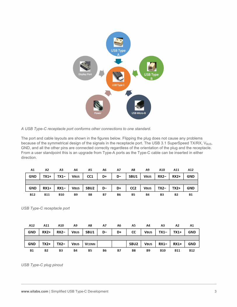
A USB Type-C receptacle port conforms other connections to one standard.
The port and cable layouts are shown in the figures below. Flipping the plug does not cause any problems because of the symmetrical design of the signals in the receptacle port. The USB 3.1 SuperSpeed TX/RX, VBUS, GND, and all the other pins are connected correctly regardless of the orientation of the plug and the receptacle. From a user standpoint this is an upgrade from Type-A ports as the Type-C cable can be inserted in either direction.
USB Type-C receptacle port
USB Type-C plug pinout

www.silabs.com | Simplified USB Type-C Development 4
USB Type-C is versatile and user-friendly, which, unfortunately, increases the internal complexity for devices that use USB Type-C. It has increased power capability (it can deliver up to 100W of power to charge a high-current device), but that creates issues for devices that don’t require that much power. This is where the Power Delivery protocol known as PD comes in. PD ensures the appropriate range of power is delivered or sourced from any connected devices.
Terminology
Before discussing USB Type-C, it is important to distinguish between the device, the host, the power supplier (source), and the power receiver (sink). The host is not always the source, therefore the terms cannot be used interchangeably. Hosts initiate all communication and devices respond. Typically, the host is the downstream facing port – or DFP – and the device is the upstream facing port – or UFP. If two hosts are connected, they can act as a dual role port – or DRP – to switch between acting as a host and a device. The following is a good terminology example: When a keyboard is connected to a laptop, the keyboard is the UFP and sink, while the laptop is the DFP and source.
Power Delivery
The initial power delivery agreement between connected devices is executed via a series of resistors acting as voltage dividers on CC wires when a Type-C plug is inserted into the receptacle. Since the CC line in the plug is either connected to CC1 or CC2 in the receptacle, the receptacle determines the orientation of the plug by simply measuring the voltages on both CC1 and CC2 lines. The different values of the pull-up resistors communicate the amount of current the source is capable of supplying, and also establishes who will be the UFP and the DFP. The power consumer does not have a way to indicate how much current it sinks through different pull-down resistor values; it has to dynamically adapt its load to match the maximum current available from the provider.
To read the voltage divider correctly, both devices need an analog processing unit, usually in the form of an accurate ADC within an MCU. The ADC measures the voltage on the CC line continuously to monitor the connection between the plug and the receptacle. The MCU is known as the PD controller, which handles the complete physical layer and upper layer protocol. It negotiates the power being delivered or received. For simple Type-C applications, the power negotiation stops with the resistors. However, for a more adaptable design, the devices can agree on a different setup by communicating over the CC line.
USB Type-C channel line topology
USB Type-C is versatile and user-friendly, which, unfortunately, increases the internal complexity for devices that use USB Type-C.

www.silabs.com | Simplified USB Type-C Development 5
Once the plug orientation and initial power is decided, the devices use the CC line to communicate with each other. Through this, the devices can agree on different levels of power and designate the sink or source, allowing for real-time power delivery adaptation. CC line communication is also used to announce which type of communication will be used. As stated before, USB Type-C can communicate on the high-speed lines, USB 2.0, and others. The devices announce which of these lines can be used via the CC line. However, not all devices support all communication protocols.
Failure Notification
A failure occurs if the two connected devices do not support one another. For example, a failure would occur if a monitor, which can only receive video from a host, is connected to a host that is unable to support or supply video data. If this occurs, the host will remain unaware of the failure because communication cannot be established. Due to this, USB Type-C standard demands an embedded device on the monitor or device side to act as a failsafe known as a Billboard device. The Billboard device signals to the host through the USB 2.0 standard on the D+ and D- lines that communication cannot be established. The host can then notify the user that the two devices are incompatible, which is shown below. Billboard devices are typically an MCU, which may be the same as the PD controller.
Billboard device failure notification
Type-C Cables and Adapters
Users who wish to use older peripherals that do not support USB Type-C need to use converting cables or dongles. There are multiple cases to account for, the first being the simple USB 2.0 to Type-C. Because USB 2.0 does not support higher speeds, and does not require more than 5V or 3A on Vbus, the cable can simply route D+/D-, Vbus, and GND to the connectors. Developing a Type-C to Type-C cable, a dongle that converts USB 3.0/1 to Type-C, or one that requires more than 5V or 3A on Vbus is more difficult.
In these cases, the dongle becomes part of the power negotiation between the two devices, requiring the cable or dongle to have an embedded PD controller. The PD controller is initially powered through Vbus set at 5V or the Vconn line. It then negotiates with the host to set an agreed power level on the Vbus line. The figure below shows an electronically marked cable assembly, or EMCA example, for connecting two Type-C devices together. The PD controller can be powered by Vconn 1 or Vconn 2. The EMCA will advertise its max power capabilities on the CC line, and the source will adapt to suit.

www.silabs.com | Simplified USB Type-C Development 6
USB Type-C to Type-C cable
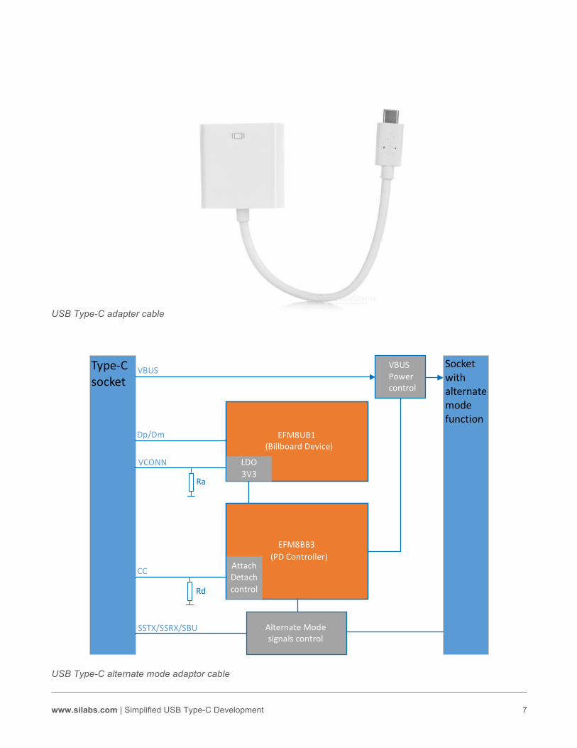
Type-C Adapter with Alternate Mode Alternate mode is the functional extension of the Type-C interface that allows Display Port, PCIe, or other communication protocols to use the USB 3.1 SuperSpeed lines. The alternate mode is entered when the adapter is connected to a compatible host. A dongle that supports alternate mode requires extra precautions and embedded devices. The dongle must inform the host if it was not able to enter the alternate mode to avoid a silent failure. It does this through the Billboard device, and USB Type-C PD standard mandates that any alternate mode accessory implements a Billboard device. The block diagram shows a cable that converts a legacy video port into Type-C. If the Type-C device does not support the legacy video format, the Billboard device will be informed by the PD controller, and will, in turn, inform the Type-C device of the failure.
EFM 8 BB 3 ( PDController )
VBUS USBType-Cplug
USB Type-Cplug
Vconn2 Vconn1
CC
SuperSpeed/HighSpeed
GND
www.silabs.com | Simplified USB Type-C Development 7
USB Type-C adapter cable
USB Type-C alternate mode adaptor cable
EFM8UB1 (BillboardDevice)
EFM8BB3 (PDController)
USBType
Attach Detach control
LDO 3 V 3
VCONN
VBUS
AlternateMode signalscontrol
VBUS Power control
Dp/Dm
CC
Socketwith alternatemodefunction
Ra
Rd
Type-Csocket
SSTX/SSRX/SBU

www.silabs.com | Simplified USB Type-C Development 8
Docking Station or Hub
A more complex example than display/Type-C to Type-C is a docking station or hub, which must support charging many devices. The hub can be a combination of multiple Type-C or Type-A ports, HDMI, PCIe, etc. This hub requires multiple embedded devices to successfully support connected devices. Each port, depending on what device is connected, will need different amounts of power. To account for this, each port may need a PD device.
Any video ports, such as display, VGA, or HDMI, will need a Billboard device. Additionally, the hub needs a device to control traffic to the host. This remains largely unchanged from the Type-A hubs, because you need to prevent collisions on the lines and ensure that only one device is communicating to the host at one time. It is clear that the previously simple hub now requires a more complex and demanding design.
Multiple connector Type-C hub cable
Solutions
All this added design complexity does not need to fall solely on developers. Silicon Labs provides development boards, PD library, Billboard source code, and example codes aimed at dongles, docking stations, and device ports. Customers can greatly reduce USB Type-C development time and efforts by using these tools when developing new Type-C devices.
Below is the development board offered by Silicon Labs that implements a Vesa® DisplayPort™ alternate mode adapter with charging capability. Developing a device like this increases the capability of a single Type-C port on a host by allowing power (charging) and video to come through one port. On the board are two PD controllers, one for each port, and a Billboard device to accompany the DisplayPort. The reference design handles switching to alternate mode, charging, informing the host of a failure, and ensuring correct power delivery to the display port and host.
Beginning on a development board like the one shown, and on the firmware provided, is less painful and faster than creating a new platform and writing firmware from scratch. With this, manufacturers and suppliers can deliver a Type-C solution with greater functionality, faster than the competition.
Silicon Labs’ MCUs like the Busy Bee 3 simplifies Type-C design with PD functionality in a single chip as small as 3x3 mm2 with precision oscillator, hardware PD PHY layer, and to provide customers a low bill of materials cost PD solution. The Universal Bee 1 used in the reference design is a single-chip solution for Billboard functionality. The integrated regulator, precision oscillator, USB 2.0 PHY layer, and ±8KV ESD protection on USB pins enable this 3x3 mm2 devise to perform Billboard function with no external components needed.

www.silabs.com | Simplified USB Type-C Development 9
Conclusion
USB Type-C is the standard of the future. The days of digging through a drawer looking for the correct conversion or cable ends are over. Going forward, choosing a cable will involve deciding whether the end is a plug or receptacle, and whether it can handle higher amounts of power. There are already smart phones, tablets, and laptops on the market that have only Type-C ports, and these pioneer devices are only the beginning. That said, Type-C requires embedded devices and firmware to handle vast functionalities, which puts a strain on developers and manufacturers as they migrate their devices. Silicon Labs has reference designs, libraries, firmware, and support teams dedicated to simplifying Type-C requirements for a wide array of applications.
About the Authors
Mark Beecham is a recent Graduate of Texas A&M university with a Bachelor of Science in electrical engineering. He is a product marketing engineer at Silicon Labs working on USB Type-C solutions.
Kafai Leung is the Senior Product Manager for Silicon Labs’ MCU products. She is also responsible for defining the company’s USB Type-C strategy. Previously, she was the design director of our Singapore Design Center and her teams developed many 8-bit and 32-bit MCU products.