tailoring the surface properties of nanotube membranes for
TRANSCRIPT

Tailoring the surface properties of
nanotube membranes for
controlled separations
Thesis submitted to the School of Chemical and Physical Sciences,
Faculty of Science and Engineering, The Flinders University of South Australia,
in fulfilment of the requirements for the degree of
Doctor of Philosophy
March 2011
Leonora Velleman
Supervisors: Prof. Joseph G. Shapter & A/Prof. Dusan Losic


ACKNOWLEDGEMENTS
I would like to present my sincere thanks to many people for their support and
guidance throughout my PhD. This thesis would not have been possible without the
encouragement, guidance and support of my supervisors, Prof Joseph Shapter and
A/Prof Dusan Losic, who fostered independent research ideas and were always
available to discuss any issues. In particular, I would like to thank my principal
supervisor, Prof Joseph Shapter, for always believing in me.
I have had the privilege to work with the smart surface structures group who have
given me valuable research advice, support and friendship. I am truly grateful for
their time and effort and for all their useful comments and assistance.
I would also like to extend a large amount of thanks to Dr François Guillaume and
Dr Jean-Luc Bruneel for their collaboration on my visit to Bordeaux University to
use their Raman spectrometer. I am very grateful for their assistance with the Raman
measurements and aid in interpreting the spectra. I would also like to thank Dr Gerry
Triani and Dr Peter Evans for the preparation of silica coated porous alumina
samples.
Finally, I would like to thank all of my family and friends for their support
throughout my PhD studies. I could not have done any of this without their support.

DECLARATION
I certify that the work presented in this thesis is, to the best of my knowledge and
belief, original unless otherwise acknowledged. The material in this thesis has not
been submitted, either in whole or in part, towards another degree at this or any other
institution.
Leonora Velleman

LIST OF PUBLICATIONS
The following is a list of peer-reviewed publications arising from the author’s
Doctor of Philosophy degree. The thesis is based around publications 3 – 8.
1. L. Dumée, L. Velleman, K. Sears, J. Schütz, N. Finn, M. Duke, S. Gray. Control
of porosity and pore size of metal reinforced carbon nanotube membranes. 6th
conference of the Aseanian Membrane Society & 7th International Membrane
Science and Technology Conference AMS6/IMSTEC10, Sydney, Australia, 2010,
submitted.
2. L.Velleman, C.J. Shearer, A.V. Ellis, D. Losic, N.H. Voelcker, J.G. Shapter,
Fabrication of self-supporting porous silicon membranes and tuning transport
properties by surface functionalisation. Nanoscale, 2010, DOI:
10.1039/c0nr00284d.
3. L. Velleman, D. Losic, J.G. Shapter. Gold nanotube membranes; fabrication of
controlled pore geometries and tailored surface chemistries. International
Conference on Nanoscience and Nanotechnology ICONN, Sydney, Australia,
2010, submitted.
4. L.Velleman, G. Triani, P.J. Evans, J.G. Shapter, D. Losic. Structural and
chemical modification of porous alumina membranes. Microporous and
Mesoporous Materials 126 (2009) 87–94.
5. L. Velleman, J.G. Shapter, D. Losic. Gold nanotube membranes functionalised
with fluorinated thiols for selective molecular transport. Journal of Membrane
Science, 328 (2009) 121-126.
6. L. Velleman, J.G. Shapter, D. Losic, Engineered gold nanotube membranes for
molecular separations. International Conference on Nanoscience and
Nanotechnology ICONN, Melbourne, Australia, 2008, art. no. 4639252, pp. 86–
89.

7. L. Velleman, J.G. Shapter, and D. Losic. Template fabricated gold nanotube
membranes: a nucleation and growth study. 15th AINSE Conference on Nuclear
and Complementary Techniques of Analysis 326 - 329 November 2007
Melbourne.
8. L. Velleman, G. Traini, P.J. Evans, A. Atanacio, J.G. Shapter, D. Losic. Atomic
layer deposition of SIO2 on porous alumina membranes: controlling the pore size
and transport properties. Proc. SPIE, Vol. 7267 (2008) 72670S;
DOI:10.1117/12.810716

i
TABLE OF CONTENTS List of Tables ................................................................................................................. v
List of Figures .............................................................................................................. vi
List of symbols and abbreviations ................................................................................ xi
Chapter 1 Introduction ............................................................................................... 1
1.1. Overview ........................................................................................................... 2
1.2. Membrane materials and their applications ....................................................... 3
1.3. Diffusion through membranes ........................................................................... 7
1.4. Porous membranes with uniform and ordered architectures ............................. 8
1.4.1. Polycarbonate track etched membranes ...................................................... 9
1.4.2. Porous alumina membranes....................................................................... 10
1.5. Electroless deposition of gold ......................................................................... 11
1.6. Separation studies ............................................................................................ 15
1.6.1. Size based molecular separations .............................................................. 15
1.6.2. Functionalised membranes for enhanced and selective separations ......... 17
1.7. Switchable membranes .................................................................................... 20
1.8. Thesis outline .................................................................................................. 23
1.9. References ....................................................................................................... 26
Chapter 2 Experimental Details .............................................................................. 37
2.1. Membrane Fabrication .................................................................................... 38
2.1.1. Fabrication of porous alumina (PA) membranes ...................................... 38
2.1.2. Fabrication of gold nanotube membranes ................................................. 38
2.1.3. Fabrication of silica modified porous alumina membranes via atomic
layer deposition ........................................................................................................... 40
2.2. Surface functionalisation of membranes ......................................................... 41
2.2.1. Thiol functionalisation of gold coated membranes ................................... 41
2.2.2. Functionalisation of silica modified alumina membranes ........................ 41
2.3. Characterisation of membranes ....................................................................... 42
2.3.1. Scanning and transmission electron microscopy ....................................... 42
2.3.2. Dynamic secondary ion mass spectrometry (SIMS) and ellipsometry
characterisation of silica coated PA membranes ........................................................ 43
2.3.3. Electrochemical characterisation of gold nanotube membranes ............... 43

ii
2.3.4. Contact angle measurements ..................................................................... 44
2.3.5. Raman spectroscopy of 3-mercaptobenzoic acid on gold coated PA
membranes .................................................................................................................. 45
2.4. Investigation of the transport properties of membranes .................................. 45
2.4.1. Transport experiments............................................................................... 45
2.4.2. Measurement of dye oil:water partition coefficients ................................ 46
2.5. Synthesis of fluorinated azobenzene for the development of switchable
membranes .................................................................................................................. 48
2.5.1. Synthesis of 4-(4-trifluoromethoxyphenylazo)phenol (1) ........................ 48
2.5.2. Synthesis of 7-[(trifluoromethoxyphenylazo)phenoxy]pentanoic acid (2) 49
2.6. References ....................................................................................................... 50
Chapter 3 Raman spectroscopy of thiols adsorbed inside the pores of gold-
alumina membranes .................................................................................................... 51
3.1. Introduction ..................................................................................................... 52
3.2. Experimental details ........................................................................................ 53
3.2.1. Fabrication of porous alumina membranes ............................................... 53
3.2.2. Electroless gold deposition ....................................................................... 54
3.2.3. Thiol functionalisation of gold nanotube membranes............................... 54
3.2.4. Raman spectroscopy of MBA on Au-PA membranes .............................. 54
3.3. Results and Discussion ................................................................................... 54
3.3.1. Structural characterisation of gold – alumina (Au-PA) membranes ........ 54
3.3.2. Characterisation of SAMs within the pores of Au-PA membranes by
Raman spectroscopy ................................................................................................... 58
3.4. Conclusion ...................................................................................................... 63
3.5. References ....................................................................................................... 64
Chapter 4 Comparison of alkanethiol and fluorinated thiols on the transport
properties of gold coated polycarbonate membranes .................................................. 66
4.1. Introduction ..................................................................................................... 67
4.2. Experimental details ........................................................................................ 68
4.2.1. Electroless gold deposition onto polycarbonate membranes .................... 68
4.2.2. Investigation of gold nanotube membrane transport properties ................ 68
4.3. Results and discussion .................................................................................... 68
4.3.1. Fabrication and characterisation of gold - polycarbonate membranes ..... 68

iii
4.3.2. Electrochemical characterisation of thiol modified gold - polycarbonate
membranes ................................................................................................................... 70
4.3.3. Transport and selectivity of gold - polycarbonate membranes ................. 72
4.4. Conclusions ..................................................................................................... 76
4.5. References ....................................................................................................... 78
Chapter 5 The effects of surface functionality positioning on the transport
properties of membranes ............................................................................................. 81
5.1. Introduction ..................................................................................................... 82
5.2. Experimental details ........................................................................................ 83
5.2.1. Electroless gold deposition ........................................................................ 83
5.2.2. Gold sputtering onto polycarbonate membranes ....................................... 84
5.2.3. Investigation of membrane transport properties ........................................ 84
5.3. Results and Discussion .................................................................................... 84
5.3.1. Fabrication and characterisation of gold - polycarbonate membranes ...... 84
5.3.2. Surface functionalisation of gold - polycarbonate membranes ................. 88
5.3.3. Transport properties of gold – polycarbonate membranes ........................ 90
5.4. Conclusion ....................................................................................................... 97
5.5. References ....................................................................................................... 99
Chapter 6 Structural and chemical modification of porous alumina membranes . 101
6.1. Introduction ................................................................................................... 102
6.2. Experimental details ...................................................................................... 103
6.2.1. Fabrication and functionalisation of silica modified porous alumina
membranes via atomic layer deposition .................................................................... 103
6.2.2. Investigation of membrane transport properties ...................................... 104
6.3. Results and Discussion .................................................................................. 105
6.3.1. Characterisation of modified porous alumina membranes ...................... 105
6.3.2. Transport and selectivity of modified PA membranes ............................ 111
6.4. Conclusions ................................................................................................... 115
6.5. References ..................................................................................................... 117
Chapter 7 Forward osmosis through silica modified porous alumina membranes .. 120
7.1. Introduction ................................................................................................... 121
7.2. Experimental details ...................................................................................... 122

iv
7.2.1. Fabrication and functionalisation of silica modified porous alumina
membranes via atomic layer deposition .................................................................... 122
7.2.2. Water transport experiments ................................................................... 122
7.3. Results and Discussion ................................................................................. 124
7.3.1. Dye dependence on the water transport through Si-PA membranes ...... 124
7.3.2. Comparison of water transport through bare PA and Si-PA ................... 127
7.3.3. Effect of salt concentration on the water transport properties ................ 128
7.4. Conclusions and further work ....................................................................... 134
7.5. References ..................................................................................................... 136
Chapter 8 Light switchable transport through gold nanotube membranes ......... 138
8.1. Introduction ................................................................................................... 139
8.2. Experimental Details ..................................................................................... 141
8.2.1. Fabrication of porous alumina membranes ............................................. 141
8.2.2. Electroless gold deposition onto porous alumina membranes ................ 141
8.2.3. Synthesis of 7-[(trifluoromethoxyphenylazo)phenoxy]pentanoic acid ... 141
8.2.4. Azobenzene functionalisation of gold nanotube membranes ................. 141
8.2.5. Investigation of membrane transport properties ..................................... 141
8.3. Results and Discussion ................................................................................. 142
8.3.1. Characterisation of gold coated alumina membranes ............................. 142
8.3.2. Characterisation of switchable azobenzene thiol on Au-PA membranes 143
8.3.3. Switchable transport properties of azobenzene modified Au-PA
membranes ................................................................................................................ 144
8.4. Conclusions ................................................................................................... 146
8.5. References ..................................................................................................... 148
Chapter 9 Concluding remarks .............................................................................. 151
9.1. Future directions ........................................................................................... 154
Appendix …………………………………………………………………………..158

v
LIST OF TABLES
CHAPTER 4
Table 4-1. Transport and selectivity properties of functionalised and bare gold
nanotube membranes (errors obtained from three replicate measurements). ............. 72
CHAPTER 5
Table 5-1 Advancing contact angle measurements for the unfunctionalised and PFDT
functionalised Au-PC membranes. ............................................................................. 90
Table 5-2 Transport and selectivity properties of functionalised and bare gold
membranes (errors obtained from three replicate measurements). ............................ 91
CHAPTER 6
Table 6-1 Summary of permeation data of hydrophobic (tris(2,2’-
bipyridyl)dichlororuthenium(II) hexahydrate, Rubpy) and hydrophilic (rose bengal,
RB) through perfluorodecyldimethylchlorosilane (PFDS) functionalised and
unfunctionalised ALD silica modified PA membranes (Si-PA). PA membranes with
20 nm pores, modified by 5 ALD cycles were used. ............................................... 112
CHAPTER 7
Table 7-1 List of dye molecules which facilitate and do not facilitate water transport
though Si-PA membranes. ........................................................................................ 126
Table 7-2 Summary of permeation data of RB (water transport facilitating dye) and
Rubpy (non-water transport facilitating dye) through Si-PA membranes. .............. 133
CHAPTER 8
Table 8-1 1 L water drop contact angle on azo and decanethiol modifed Au-PA
membranes. ............................................................................................................... 143
Table 8-2 Flux data for EY transport through unfunctionalised and azo-
functionalised cis and trans state Au-PA membranes. ............................................. 145
APPENDIX
Table A-1 Transport and selectivity properties of functionalised and bare gold
membranes (errors obtained from three replicate measurements). .......................... 158

vi
LIST OF FIGURES Figure 1-1 Schematics of the principal types of membranes [49]. .............................. 4
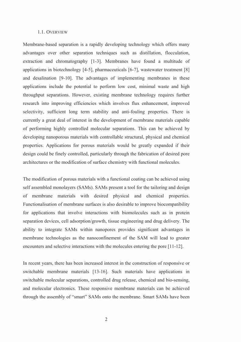
Figure 1-2 SEM images of typical polymer (a) and ceramic (b) membranes generally
used in commercial applications [67-68]. .................................................................... 9
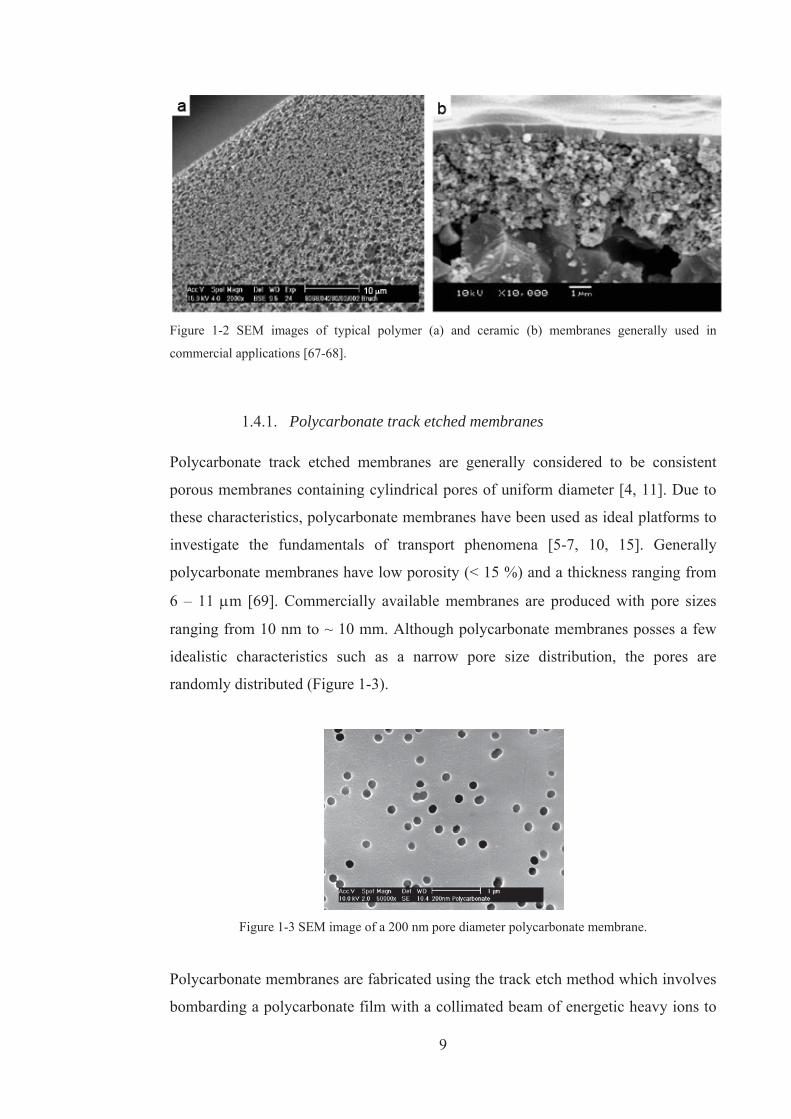
Figure 1-3 SEM image of a 200 nm pore diameter polycarbonate membrane. ........... 9
Figure 1-4 Fractures of track etched membranes. Etching with (a) 6 M NaOH, (b) 6
M NaOH + 0.01% DBSNa, (c) 6 M NaOH + 0.05% Dowfax. Scale bar: 1 m [71].10
Figure 1-5 SEM image of a porous alumina membrane viewed from the top (a) and
cross section (b). ........................................................................................................ 11
Figure 1-6 Schematic of the electroless deposition onto porous templates to obtain
gold nanotube membranes. ........................................................................................ 13
Figure 1-7 Schematic of the electroless deposition process. ..................................... 13
Figure 1-8 SEM images of Au tubes obtained after dissolution of the PC membrane,
(a) deposition time of 1 h, (b) deposition time of 48 h [91]. ...................................... 14
Figure 1-9 (a) TEM image showing scalloped nature exhibited by nanowires and
nanotubes. (b) SEM image exhibiting non-uniform wall thickness near the end of the
nanotube [72]. ............................................................................................................ 15
Figure 1-10 Schematic of the separation of molecules based on size exclusion. ...... 16
Figure 1-11 Amounts of moles of MV2+ and Ru(bpy)32- transported versus time.
Membranes contained gold nanotubes with an inner tube diameter of 3.2 nm [2]. ... 17
Figure 1-12 Schematic of selective separation achievable by modifying the surface
properties of the membrane........................................................................................ 18
Figure 1-13 Flux plots showing toluene and pyridine transport in an i.d. = 2 nm C16
thiol modified gold nanotube membrane [100]. ......................................................... 20
Figure 1-14 Diffusion of benzenesulfonate anions across a HS(CH2)10COOH
modified gold coated PC membrane: effect of external pH [35]. .............................. 20
Figure 1-15 Schematic of the reversible change in membrane properties due to
applied external stimuli. ............................................................................................. 21
Figure 1-16 Temperature dependent water flux of pristine PC membranes and
PNIPAAM modified PC membranes with different monomer concentrations [110].22
Figure 2-1 Cross sectional schematic of porous alumina fabrication. ....................... 39
Figure 2-2 (a) Schematic and photo of the permeation cell set up used in these
studies. (b) Photo of the Ocean Optics UV-Vis system. ............................................ 47

vii
Figure 2-3 Structures of probe dye molecules used in the transport experiments. .... 48
Figure 2-4 Scheme of the synthesis of 4-(4-trifluoromethoxyphenylazo)phenol (1)
(intermediary) and 7-[(trifluoromethoxyphenylazo)phenoxy]pentanoic acid (2). ..... 49
Figure 3-1 Schematic of electrolessly gold coated porous alumina membranes and
functionalisation of the gold surfaces with 3-mercaptobenzoic acid. ........................ 53
Figure 3-2. SEM images of a) the surface of an Au-PA membrane and b) an area of
the membrane where the gold surface layer was cleaved exposing the tips of the gold
nanotubes formed within the pores. c) cross section of the Au-PA membrane. d) pore
size distribution of Au-PA membranes. ..................................................................... 56
Figure 3-3 SEM images of a section of liberated gold nanotubes after dissolution of
the porous alumina from the top of the membrane (a) and from the centre of the
membrane (b). EDAX analysis of the nanotube array confirming their composition of
gold (c). ...................................................................................................................... 57
Figure 3-4 Normal Raman spectrum of pure mMBA (a) and SERS spectrum of an
mMBA monolayer on gold (b). Normal Raman spectrum of solid mMBA (c) and
SERS spectrum of mMBA on an Au-PA membrane (d) over an extended
wavenumber range. .................................................................................................... 59
Figure 3-5 Raman spectra of mMBA when it is attached to the top surface (a) and
within the pores (b) of the gold coated membrane. .................................................... 60
Figure 3-6 a) Raman spectra of the cross section of an mMBA functionalised Au-PA
membrane. b) Plot of the peak height obtained at 1000 cm-1 for 4 m increments
across a cross section of an Au-PA membrane. Scans were taken in 4 m increments
starting above the top surface of the membrane. Position 0 m is the position of the
laser at the starting point of the line scan. The line scan finishes below the bottom
surface of the membrane. ........................................................................................... 62
Figure 3-7 Schematic of a cross section of Au-PA exhibiting a bottle neck shaped
pore. ............................................................................................................................ 63
Figure 4-1. a) SEM image showing the surface morphologies of gold nanotube
membranes prepared using a polycarbonate membrane as the template with a
nominal pore diameter of 80nm. Inset: uncoated polycarbonate membrane. b) TEM
cross section of 30nm PC membrane plated with gold for 20h. c) Fully dissolved PC
membrane resulting in a standing array of gold nanotubes supported by the surface

viii
gold layer (PC pore diameter: 800 nm). d) Surface etched Au-PC membrane
revealing the tips of the gold nanotubes (PC pore diameter: 200 nm). ...................... 69
Figure 4-2. Typical CVs obtained for unmodified, and thiol-modified gold nanotube
membranes, PFDT-Au-PC and DT-Au-PC in (a) an electron-transfer experiment
performed using a redox probe 1 mM ferricyanide in 0.2 M KCl (scan rate 100
mVs 1) and (b) a gold reduction experiment performed in 0.1 M sulphuric acid (scan
rate 100 mVs 1). ......................................................................................................... 71
Figure 4-3 Transport of a hydrophobic (PCN) and hydrophilic (RB) dye through a
gold nanotube membrane functionalised with the hydrophobic thiols a) decanethiol
and b) perfluorodecanethiol. ...................................................................................... 75
Figure 4-4 Transport of the hydrophilic dye (RB) through an unfunctionalised
membrane and membranes functionalised with decanethiol and perfluorodecanethiol.
.................................................................................................................................... 76
Figure 5-1 Schematics of the hybrid gold-polycarbonate structures investigated in
this study; (a) unmodified PC, (b) Au(ext+pore)PC, (c) Au(pore)PC and (d) Au(ext)PC and
corresponding cross sectional images of the membranes after functionalisation,
displaying the areas PFDT is adsorbed on. ................................................................ 83
Figure 5-2 SEM images of the surface of the a) Au(ext+pore)PC, b) Au(pore)PC and c)
Au(ext)PC membranes used in this study. Inset: 30 nm unmodified PC membrane. .. 86
Figure 5-3 SEM images of (a) Au(ext+pore)PC membrane and (b) Au(pore)PC membrane
based on 80 nm pore size polycarbonate membranes. Inset: uncoated polycarbonate
membrane. .................................................................................................................. 87
Figure 5-4 TEM images of the cross section of (a) Au(ext+pore)PC, (b) Au(pore)PC and
(c) Au(ext)PC membranes. The dark regions are region of high gold concentrations.
Insets: schematics of their corresponding membrane cross-section. ......................... 88
Figure 5-5 Transport of hydrophobic (PCN) and hydrophilic (RB) dye through
unmodified and PFDT- modified (a) Au(ext+pore)PC (b) Au(pore)PC and (c) Au(ext)PC
membrane. .................................................................................................................. 93
Figure 5-6 Concentration profiles for RB across PFDT modified a) Au(ext+pore)PC, b)
Au(pore)PC and c) Au(ext)PC membranes. .................................................................... 96
Figure 6-1 Schematic of the structural and chemical modification of PA membranes
which includes (a) bare membrane, (b) atomic layer deposition (ALD) of silica, (c)
hydroxylation step by water plasma and (d) functionalisation of silica modified PA

ix
membranes by perfluorodecyldimethylchlorosilane (PFDS). The top of the pores is
presented. .................................................................................................................. 104
Figure 6-2 The reduction of pore diameters of PA membranes by ALD deposition of
silica using different numbers of cycles. SEM images of PA membranes (20 nm
pores) before (a) and after silica modification using (b) 3 ALD cycles, (c) 5 ALD
cycles and (d) 7 ALD cycles. ................................................................................... 106
Figure 6-3 The correlation of the pore diameters and number of ALD cycles (PA
membranes with 20 nm pores). ................................................................................ 107
Figure 6-4 SEM images of PA membranes with larger pore diameters (100 and 200
nm) before and after ALD silica modifications. (a–c) PA membrane (100 nm pores)
before (a) and after ALD deposition using (b) 10 ALD cycles and (c) 20 ALD cycles.
(d–f) PA membrane (200 nm pores) before (d) and after ALD deposition using (e) 20
ALD cycles with (f) corresponding to a cross-section image. ................................. 108
Figure 6-5 (a) The depth profile of an Si-PA membrane displaying the distribution of
Si, obtained by dynamic SIMS analysis using a Cs+ primary ion beam rastered from
the top of the Si-PA membrane (20 nm pores, 3 cycles), (b) EDAX analysis graphs
from Si-PA prepared by (b) 5 and (c) 10 ALD cycles. ............................................ 110
Figure 6-6 Images of a water droplet on (a) an unmodified Si-PA membrane (b) a
PFDS modified Si-PA membrane (20 nm pores, 5 ALD cycles). ............................ 111
Figure 6-7 Transport of a hydrophobic (Rubpy) and a hydrophilic dye (RB) through
(a) unmodified silica PA membranes (Si-PA) and (b)
perfluorodecyldimethylchlorosilane (PFDS) modified Si-PA membranes (20 nm
pores, 5 ALD cycles). ............................................................................................... 113
Figure 7-1 Schematic of the forward osmosis process. The feed cell is filled with
water or contaminated water (e.g. seawater). The draw cell is filled with a highly
concentrated solution. The water passes through the semi-permeable membrane due
to the increased osmotic pressure across the membrane. ......................................... 121
Figure 7-2 Photographs of a permeation cell with Si-PA, CV and 1 M KCl at (a)
time = 0 and (b) time = 7 h. ...................................................................................... 123
Figure 7-3 Amount of water transported through Si-PA membranes after 8h when
various charged dyes are used as the permeant. ....................................................... 124

x
Figure 7-4 Water volume change in the feed cell due to water transport through Si-
PA membranes containing crystal violet (CV) or rose bengal (RB) in the feed cell.
.................................................................................................................................. 125
Figure 7-5 Amount of water transported for PA and Si modified PA after 400 min
when CV or RB is used as the permeant. ................................................................. 127
Figure 7-6 SEM images of (a) an unmodified PA membrane and (b) a Si-PA
membrane. ................................................................................................................ 128
Figure 7-7 Volume change in the draw (a) and feed (b) cell due to water transport
through Si-PA membranes containing crystal violet (CV) in the draw cell and
varying KCl concentrations in the solvent. .............................................................. 130
Figure 7-8 Volume change in the draw (a) and feed (b) cell due to water transport
through Si-PA membranes containing rose bengal (RB) in the draw cell and varying
KCl concentrations in the solvent. ........................................................................... 131
Figure 7-9 Volume of water transported through Si-PA membranes after 300 min for
varying KCl concentrations when crystal violet (a) or rose bengal (b) is in the draw
cell. ........................................................................................................................... 132
Figure 7-10 Transport of Rubpy and RB through a Si-PA membrane. ................... 133
Figure 8-1 Schematic of gold coated alumina membrane with adsorbed azobenzene
thiol layer and its reversible photisomerisation between the trans and cis states. ... 140
Figure 8-2 SEM images of the suface of a gold nanotube membrane after 16 h of
gold deposition (a) and the cross sectional view of the gold nanotube membrane (b).
.................................................................................................................................. 142
Figure 8-3 Transport of the hydrophilic dye (EY) across the azobenzene modified
membrane when switched between the trans (highly hydrophobic) and cis (less
hydrophobic) states. ................................................................................................. 144
Figure 8-4 Schematic representation of the assembly of the azobenzene layer within
a pore (top view) in the trans state (a) and the cis state (b). ..................................... 145

xi
LIST OF SYMBOLS AND ABBREVIATIONS
ALD
APTES
Au
Au-PC
Au-PA
Au(ext-pore)PC
Au(pore)PC
Au(ext)PC
BG
CV
CVD
DT
EDAX
EDC
EY
FIB
FO
FTIR
LCST
MBA
MV
NEXAFS
NHS
NS
PA
PC
PCN
PDMS
PF
PFDS
PFDT
Atomic layer deposition
Aminopropyltriethoxy silane
Gold
Gold coated polycarbonate
Gold coated porous alumina
Gold coated polycarbonate on the interfaces and inside pores
Gold coated polycarbonate only within the pores
Gold coated polycarbonate only on the interface
Bromocresol green
Cyclic voltammetry
Chemical vapour deposition
1-Decanethiol
Energy dispersive analysis X-ray spectroscopy
1-Ethyl-3-[3-dimethylaminopropyl]carbodiimide hydrochloride
Eosin yellow
Focussed ion beam
Forward osmosis
Fourier transform infrared spectroscopy
Lower critical solution temperature
Mercaptobenzoic acid
Methyl viologen
Near Edge X-ray Absorption Fine Structure
N-hydroxy succinimide
Nickel sulphate
Porous alumina
Polycarbonate
Pinacyanol chloride
Polydimethylsiloxane
Potassium ferricyanide
Perfluorodecyldimethylchlorosilane
Perfluorodecanethiol

xii
PNIPAAM
RB
RhB
RO
Rubpy
SAM
SEM
Si
Si-PA
SIMS
SERS
TEM
TMA
UV-Vis
XPS
Poly(N-isopropylacrylamide)
Rose bengal
Rhodamine B
Reverse osmosis
tris(2,2’-bipyridyl)dichlororuthenium(II) hexahydrate
Self assembled monolayer
Scanning electron microscopy
Silica
Silica coated porous alumina
Secondary ion mass spectrometry
Surface enhanced Raman scattering
Transmission electron microscopy
Trimethyl aluminium
Ultraviolet – Visible
X-ray photoelectron spectroscopy

xiii
ABSTRACT
Membrane-based separation is a rapidly developing technology which offers many
advantages over other separation techniques. However, existing membrane
technology requires further research into improving efficiencies which involves flux
enhancement, improved selectivity, sufficient long term stability and anti-fouling
properties. The fabrication of membrane materials capable of performing highly
controlled molecular separations can be achieved by developing nanoporous
materials with controllable structural, physical and chemical properties. Recently
there has been increased interest in the functionalisation of membrane surfaces in
order to enhance the stability and transport properties of membranes. However,
current research into the characterisation of functional layers within porous materials
is lacking. Further insight into how surface modifications may impact the transport
properties of porous membranes is essential for the development of membrane
materials.
This thesis presents an approach for tailoring porous materials with surface
functionalities and controlling pore architecture to provide controlled transport
properties. Membranes such as polycarbonate and porous alumina membranes were
used in these studies due to their ordered pore architectures. Further structural
modification of the membranes was carried out in order to reduce the pore diameter
of the membranes. Pore size reduction was achieved using two methods; electroless
deposition of gold and atomic layer deposition (ALD) of silica. The pore size of the
membranes was altered systematically by adjusting the number of ALD cycles or by
adjusting gold deposition time.
The surface properties of the membranes were tailored in order to provide controlled
molecular transport. It is important to determine how surface modifications may
impact the transport properties of porous membranes in order to devise more
efficient separation processes. Desired chemical properties were imparted to the
membranes by modifying the membrane surfaces with self assembled monolayers
(SAMs). Predominantly, hydrophobic SAMs were used as it presented a simple
technique to demonstrate changes to the transport properties of membranes due to

xiv
introduced surface functionalities. The transport properties of fluoro-derivatised
membranes (1H,1H,2H,2H-perfluorodecanethiol) towards hydrophobic and
hydrophilic molecules was compared with a membrane modified with an analogous
alkanethiol; 1-decanethiol to demonstrate the influence that a slight variance in
surface modification can have on the transport properties of the membrane. The
effects of the controlled positioning of functional groups on the transport properties
of the membrane were investigated. Several hybrid membrane structures based on
polycarbonate membranes were created in which gold was deposited on different
areas on the membrane; on one of the membrane interfaces, within the pores of the
membrane and completely coating all surfaces of the membrane. Gold-thiol
chemistry was exploited in which the thiols only assembled on the gold coated
regions of the membrane thus providing controlled positioning of functional regions.
Lastly, silica coated PA membranes were functionalised with
perfluorodecyldimethylchlorosilane (PFDS) to demonstrate that the transport and
selectivity properties of silica composite PA membranes can be varied by
functionalisation using silane chemistry.
The investigation of the coverage and reproducibility of SAMs within porous
matrices is of utmost importance in the design of filtration membranes and sensing
platforms. The surface enhanced Raman scattering (SERS) effect was employed to
confirm and characterise the formation of SAMs of 3-mercaptobenzoic acid
(mMBA) on the surfaces of the gold coated alumina membranes.
To explore more sophisticated surface functionalisation, stimuli responsive
membranes were produced. The transport properties of the gold nanotube membranes
were controlled through the reversible switching of adsorbed fluorinated azobenzene
layers. The fluorinated, hydrophobic end group of the azobenzene chain produces a
transition between hydrophobic and less hydrophobic surface properties when
switching from the trans to the cis state. The selective mediation of a hydrophilic
probe dye across the membrane was investigated.

CHAPTER 1 INTRODUCTION 1. Chapter 1Chapter
2
1.1. OVERVIEW
Membrane-based separation is a rapidly developing technology which offers many
advantages over other separation techniques such as distillation, flocculation,
extraction and chromatography [1-3]. Membranes have found a multitude of
applications in biotechnology [4-5], pharmaceuticals [6-7], wastewater treatment [8]
and desalination [9-10]. The advantages of implementing membranes in these
applications include the potential to perform low cost, minimal waste and high
throughput separations. However, existing membrane technology requires further
research into improving efficiencies which involves flux enhancement, improved
selectivity, sufficient long term stability and anti-fouling properties. There is
currently a great deal of interest in the development of membrane materials capable
of performing highly controlled molecular separations. This can be achieved by
developing nanoporous materials with controllable structural, physical and chemical
properties. Applications for porous materials would be greatly expanded if their
design could be finely controlled, particularly through the fabrication of desired pore
architectures or the modification of surface chemistry with functional molecules.
The modification of porous materials with a functional coating can be achieved using
self assembled monolayers (SAMs). SAMs present a tool for the tailoring and design
of membrane materials with desired physical and chemical properties.
Functionalisation of membrane surfaces is also desirable to improve biocompatibility
for applications that involve interactions with biomolecules such as in protein
separation devices, cell adsorption/growth, tissue engineering and drug delivery. The
ability to integrate SAMs within nanopores provides significant advantages in
membrane technologies as the nanoconfinement of the SAM will lead to greater
encounters and selective interactions with the molecules entering the pore [11-12].
In recent years, there has been increased interest in the construction of responsive or
switchable membrane materials [13-16]. Such materials have applications in
switchable molecular separations, controlled drug release, chemical and bio-sensing,
and molecular electronics. These responsive membrane materials can be achieved
through the assembly of “smart” SAMs onto the membrane. Smart SAMs have been

3
fabricated with reversible properties through changes in wettability [17-18], charge
[19], adhesion [20], and biocompatibility [21-23].
In addition to tailoring the surface chemistry of membranes, there has been recent
focus on the development of new membrane materials and porous structures.
Nanotube membranes have been recently introduced by depositing a thin layer of
material such as gold, silica, carbon and metal oxides inside the pores of a template
membrane [24-28]. Amongst them, the gold nanotube membrane has received
considerable interest for applications in molecular separations [2, 29-30] due to the
properties of gold such as chemical inertness, thermal stability, conductivity and the
ability to tailor surface properties by chemical and biochemical functionalisation [31-
37]. Gold nanotube membranes are highly ordered membranes fabricated through the
electroless deposition of gold onto a template membrane [29]. They have received
much attention due to the ease and simplicity of surface modifications with thiols and
the limitless capacity for additional surface modifications through coupling to the
thiol anchors [1, 11, 35]. Through the correct pairing of thiols to target molecules,
selective or enhanced transport can be achieved.
1.2. MEMBRANE MATERIALS AND THEIR APPLICATIONS
A membrane is a thin sheet of a natural or synthetic material which moderates the
transport of chemical species in contact with it. The material can be various
thicknesses, with homogeneous or heterogeneous structures, and differing pore sizes.
The main categories of membrane structures are shown schematically in Figure 1-1.
Studies to date have demonstrated the ability of nanoporous membranes to perform
selective transport and separation of molecules including gases [38], metal ions [39],
anions, small organic molecules [40], drugs [41], proteins and nucleotides [34, 42-
43]. The simplest strategy for molecular filtration is based on separation by
molecular size. Other selectivity processes have been performed such as selectivity
based on ionic charge [44], electro-osmotic flow [45], electrophoretic [46] and
electrokinetic transport [47].

4
The main interests in membrane science and technology have been fuelled by the
need for sustainable and eco-friendly technologies. Membranes offer simplicity,
efficiency, high selectivity, low energy consumption, stability and ease of up-scaling.
The membrane industry spans numerous diverse fields where US membrane
applications alone is a multi-billion dollar market [48]. Industrial applications
include water desalination, water treatment, gas separation, gas storage,
microfiltration and pervapouration. Medical applications include controlled drug
release, artificial organs and tissue regeneration.
Figure 1-1 Schematics of the principal types of membranes [49].
Membrane technology has become commonplace in water treatment industries. The
implementation of membrane systems in water treatment has resulted in decreased
running costs leading to a reduction in reclaimed water prices. Reverse osmosis is
presently the fastest growing technology in the desalination industry. It is now
considered worldwide as the most promising technology for resolving freshwater

5
scarcity [48]. Reverse osmosis membranes are generally made from polymers and
are dense materials which are permeable to water but impermeable to salt, hence
enabling the separation of water and salt ions [49].
Membrane based gas separations is a rapidly growing industry with future prospects
improving as membrane technology successfully competes against adsorption,
absorption and cryogenic technologies. The gas separation industry utilises
membranes for the removal of nitrogen and water from air, carbon dioxide from
natural gas and the refinement of gasses. The main application for membranes in the
gas separation industry is for the separation of nitrogen from air. Nitrogen production
represents more than half of the membrane based gas separation industry [48].
However, the largest gas separation industry, by amount of gas treated, is in the
refinement of natural gas. While membranes have only attained a small percentage of
the natural gas market, membrane implementation in this field is steadily growing.
The separation of carbon dioxide from natural gas is of utmost importance for
overgrowing concerns for global warming. In particular, the separation of carbon
dioxide from industrial fumes is an objective of current research groups worldwide.
Membrane materials are regarded as highly suitable for biomedical applications due
to mild operating conditions such as low pressure and temperature thereby preserving
the original biological activity. Furthermore for membrane separations additional
solvents do not need to be added therefore avoiding possible contamination.
Additionally, a variety of membrane materials are available, many of which are
biocompatible and highly anti-fouling. Medical applications requiring membranes
include the recovery and purification of biologically active molecules [50],
hemodialysis [51], artificial organs [5], drug delivery [52], tissue engineering and
regenerative medicine [53]. Biologically active compounds such as proteins, DNA,
RNA and more recently small bioactive molecules are required to be recovered and
refined from highly complex media. Furthermore, membrane materials have recently
been employed in controlled drug delivery devices. It is expected that bioactive
molecule recovery and drug delivery will excel with the upcoming development of
membranes which are responsive to external stimuli such as pH, temperature and
UV-Vis irradiation. The most important application of membranes in biomedical
applications is in haemodialysis [54], for the treatment of end stage renal disease.

6
Membranes are also used for blood oxygenation during cardiac surgery and
respiratory failure [55]. Furthermore membranes have been used for plasma
separation and for cholesterol removal [56]. Emerging applications for membranes in
the medical field include artificial organs such as liver, kidney and pancreas and
regenerative medicines [48]. As the liver is highly complex and performs multiple
functions, artificial livers have thus far only able to perform the detoxification
functions of the liver. Therefore promising research has concentrated on the design
of bioartificial livers [57]. The fields of tissue engineering and regenerative medicine
utilise membrane materials as scaffolding or supporting materials for biological
materials. The formation of new tissue can be achieved through using membrane
materials as cell supports [58]. Through this technique hybrid materials can be
constructed for inducing tissue regeneration in patients and for replacing failing
organs.
The membranes employed in the above applications fall into several categories:
polymer, inorganic and hybrid organic-inorganic membranes. Membrane
applications are mainly dominated by polymer membranes as they are readily
commercially available, they offer substantial variety in regards to composition and
porosity and are easily fabricated with a large membrane area. Furthermore polymer
membranes are generally considered consistent, reliable and cost effective.
Considerable research is focussed on tailoring these polymeric materials to suit
specific applications through modifying their pore geometries and physical
properties. However, polymeric membranes have limitations. Well-defined pore
architectures are difficult to achieve and in general they have poor chemical
resistance, thermal stability and mechanical strength. Therefore inorganic membrane
materials are gaining interest due to their high thermal and chemical stabilities and
greater mechanical strength. Particular inorganic membranes such as porous alumina
and zeolites consist of highly uniform and ordered pore architectures [59].
Unfortunately inorganic membranes tend to be brittle and more expensive than their
polymer counterparts and are therefore generally dismissed in large commercial
industries such as water treatment. Recently hybrid organic-inorganic membranes
have gained considerable interest [60-61]. They are comprised of either inorganic
membranes coated in organic layers or inorganic porous materials embedded into a

7
polymer matrix. These membranes offer improved performance in regards to
selectivity, permeability and stability.
1.3. DIFFUSION THROUGH MEMBRANES
Molecules dissolved in liquids or gases are continually and randomly moving. When
there are areas of differing concentrations of molecules in the solvent the molecules
will diffuse from areas of high concentration to low concentration. The concept of
diffusion was mathematically described by Adolf Fick, a physician who derived
Fick’s laws of diffusion in 1855 [62]. Fick’s laws are often used to describe and
model membrane transport properties observed in osmosis, reverse osmosis, gas
permeation, drug delivery and cell membrane functions [63]. Fick’s first law of
diffusion [62] states that the net rate of diffusion is;
dxdCDJ (1)
where the rate of diffusion or flux, J, is proportional to the concentration gradient,
dxdC , and a proportionality constant termed the diffusion coefficient, D. The minus
sign indicates that the diffusion is in the direction of higher to lower concentration.
The concentration gradient is the driving force behind the diffusion of molecules.
The molecules will flow in the direction which will eliminate the concentration
difference. If a permeable membrane separates solutions of high and low
concentration, the molecules on the high concentration side will diffuse across the
membrane to the low concentration side. Diffusion will continue until the
concentrations on both sides of the membrane reach equilibrium.
The connection between the flux, J, and the driving force, dC/dx, is the diffusion
coefficient, D. Fick described the diffusion coefficient as “the constant depending of
the nature of the substances”. It is determined by the nature of the diffusing solute
and the nature of the membrane or medium through which diffusion takes place. The
diffusion coefficient of the solute within the membrane will differ from the diffusion
coefficient in the bulk solvent. Thus for transport across a membrane the description
of diffusion becomes more complicated and Fick’s law must be adapted [64-65].
Generally the concentration of the solute immediately within the membrane will not
be the same as the concentration in the solution adjacent to the membrane. The
distribution of the solute between the bulk solution and the membrane material is

8
described by the partition coefficient, K. The partition coefficient is the concentration
of the solute immediately within the membrane divided by the concentration in the
adjacent solution and hence describes the solute’s ability to enter the membrane. The
partition and diffusion coefficients are grouped together in a new term, the
permeability coefficient, P, which is defined as;
LKDP (2)
where L is the thickness of the membrane. Thus Fick’s first law of diffusion
becomes;
)( 21 CCPJ (3)
where C1 and C2 are the concentrations of the solutions on either side of the
membrane. The partition coefficient is often found to have a more pronounced
influence on the permeability or flux than the diffusion coefficient [66]. Therefore
the differences in diffusion tend to be less important than differences in the solute’s
affinity for or solubility in the membrane material. Consequently the permeability
coefficients of solutes are highly dependent on their partition coefficients. In other
words, the more soluble or attracted a molecule is to a membrane the greater its
permeability coefficient.
1.4. POROUS MEMBRANES WITH UNIFORM AND ORDERED ARCHITECTURES
Typically, the membranes used in commercial applications involve materials with a
non-uniform sponge-like network of pores (Figure 1-2). These membranes have
substantially differing pore sizes throughout the material resulting in a non-ideal
platform to investigate fundamentals of transport phenomena. Porous materials
which contain pores that run perpendicular to the surface with no lateral crossovers
have recently gained interest. Membranes with such structured architectures thereby
provide an ideal model for studying how pore size and surface chemistry affect the
transport properties of the membrane. Such ideal porous membranes include
polymeric track-etched and anodic alumina membranes which are commercially
available and are commonly used as tools for filtration.
9
Figure 1-2 SEM images of typical polymer (a) and ceramic (b) membranes generally used in
commercial applications [67-68].
1.4.1. Polycarbonate track etched membranes
Polycarbonate track etched membranes are generally considered to be consistent
porous membranes containing cylindrical pores of uniform diameter [4, 11]. Due to
these characteristics, polycarbonate membranes have been used as ideal platforms to
investigate the fundamentals of transport phenomena [5-7, 10, 15]. Generally
polycarbonate membranes have low porosity (< 15 %) and a thickness ranging from
6 – 11 m [69]. Commercially available membranes are produced with pore sizes
ranging from 10 nm to ~ 10 mm. Although polycarbonate membranes posses a few
idealistic characteristics such as a narrow pore size distribution, the pores are
randomly distributed (Figure 1-3).
Figure 1-3 SEM image of a 200 nm pore diameter polycarbonate membrane.
Polycarbonate membranes are fabricated using the track etch method which involves
bombarding a polycarbonate film with a collimated beam of energetic heavy ions to

10
create linear damage tracks [70-71]. The damage tracks are then chemically etched to
form cylindrical pores. Factors such as etch time and temperature determine the
diameter of the pores. Lower temperatures (~ 1-2 oC) promote even etching of the
pores to produce cylindrical pores. With higher temperatures, the etching is rapid and
the pores exhibit a cigar-like shape in which the diameter of the pore is tapered
towards the top and bottom surface of the membrane (Figure 1-4) [71].
Commercially available track etch membranes are found to exhibit these ‘cigar’
shaped pores [71-73].
Figure 1-4 Fractures of track etched membranes. Etching with (a) 6 M NaOH, (b) 6 M NaOH + 0.01%
DBSNa, (c) 6 M NaOH + 0.05% Dowfax. Scale bar: 1 m [71].
1.4.2. Porous alumina membranes
Porous materials such as porous alumina (PA) membranes possess a higher degree of
pore structure and order than polycarbonate membranes. Recently there has been
increased interest in the fabrication and characterisation of PA membranes [74-75].
Due to their aligned and uniform cylindrical pores, PA has been extensively used as
membranes in separation technologies [40, 76] and as ideal template structures for
the fabrication of nanotubes and nanowires [77-79]. The attraction of PA membranes
is based on the low cost of fabrication in comparison to other inorganic membranes,
thermal stability, order, uniformity and density of nanopores. PA membranes are
highly porous materials with porosities as high as 30-50 % [80]. Unlike
polycarbonate membranes, there is a regular distribution of the pores. However, in
comparison to polymeric membranes PA fabrication is more expensive and tends to
be more brittle and fractures easily.

11
Due to aluminium’s high affinity for oxygen, its surface is always covered in an
oxide film [81]. This film is composed of alumina (Al2O3) which is highly resistant
and provides corrosion protection to the aluminium. It is possible to make these
layers porous by using an electrochemical process called anodisation. PA forms via
self organisation where the length, diameter and density of the pores are precisely
controlled by the anodisation conditions. Factors during anodisation such as
electrolyte composition, pH and applied voltage govern the structure of the PA
formation. Porous alumina exhibits pores with hexagonal order (Figure 1-5), and can
be fabricated with pore diameters that range from 20 - 200 nm and membrane
thicknesses ranging from several microns to hundreds of microns [82-83].
Figure 1-5 SEM image of a porous alumina membrane viewed from the top (a) and cross section (b).
1.5. ELECTROLESS DEPOSITION OF GOLD
Several strategies can be used to modify the structure of porous materials including
electrochemical metal deposition, electroless metal deposition, chemical and plasma
polymerisation, sol-gel deposition and chemical vapour deposition [84]. Amongst
these deposition methods, electroless deposition is advantageous in the coating of
porous materials as this technique is not limited to the structure of the material that
can be coated. The advantage of electroless deposition is the ease of depositing
materials within thick porous membranes. The majority of the other deposition
12
methods outlined above are only capable of modifying the top surfaces of the
membrane. Other methods which are capable of depositing material within
membranes involve very complex procedures. Electroless deposition of gold onto
template membranes not only precisely controls the pore diameter [2, 29] but
additionally provides a suitable platform for further modifications with SAMs such
as thiols [31-37]. Through exploiting gold – thiol chemistry, these gold coated
membranes can be functionalised with a wide variety of thiols [85].
C.R. Martin pioneered gold nanotube membranes which utilises electroless gold
deposition [29]. This technique evenly coats the pore walls of the membrane thus
forming hollow gold nanotubes (Figure 1-6). The deposition of the gold depends on
several factors, the gold deposition time, temperature, pH and concentration of the
gold in the gold deposition bath. As deposition time continues the thickness of the
gold increases. Thus by controlling the deposition parameters the inner pore diameter
of the gold nanotubes can be decreased down to 1 nm, hence providing a tool for
molecular separations.
Briefly, the process used for electroless deposition consists of several steps as
outlined in Figure 1-7. Firstly the membrane is sensitised in a tin solution followed
by the deposition of catalytic silver nanoparticles. The membrane is then immersed
in the gold deposition bath in which gold displaces the silver nanoparticles and
further gold is reduced by formaldehyde and so the gold layer becomes thicker with
time. Although electroless deposition has predominantly been used to deposit gold
onto polycarbonate membranes, this technique is not only limited to polycarbonate
surfaces but can be used to plate various materials [77, 86-87].
The formation of electroless gold layers within porous materials has been extensively
studied by several groups. It is important to obtain homogeneous electroless
deposition in porous materials which is achieved by reducing the rate of gold
deposition. Although it appears counterintuitive to coat the surfaces in catalytic silver
nanoparticles, these nanoparticles serve another function in which the gold ions are
preferentially reduced at the surfaces containing silver nanoparticles thereby only
coating those areas with gold. The electroless deposition method deposits nanometre
sized gold particles on the pore walls and as deposition time continues these particles

13
Figure 1-6 Schematic of the electroless deposition onto porous templates to obtain gold nanotube
membranes.
Figure 1-7 Schematic of the electroless deposition process.
grow to form a compact gold layer. The size of these gold particles and their
nucleation distance is dependent on several factors including the concentration of
gold, pH and temperature of the gold deposition bath. It has been shown that with
higher temperatures, the rate of gold deposition increases and thus inhomogeneous
gold deposition occurs [72]. Gold deposition is typically carried out at 1 – 4 oC to

14
ensure a slow deposition rate to allow for fine deposited layers [29]. The reduction of
Au+ ions to elemental Au is depicted by reaction 1: 0
2 2232 AuOHHCOOOHHCHOAu (1)
The pH of the gold deposition bath is found to have a profound effect on the quality
of electroless deposition. From reaction 1, it is apparent that at neutral and acidic pH
gold deposition cannot take place. It is evident that increasing pH values will
accelerate the rate of gold deposition. Previous studies have shown that the ideal pH
for the promotion of homogeneous gold films was found to be in a range of pH 8 –
10.
Electroless deposition has been extensively employed for the fabrication of
templated nanostructures for use in applications such as in electronics [29], catalysis
[88] and sensing [89-90]. As the pores in polycarbonate and alumina membranes are
cylindrical, gold nanotubes or nanowires can be formed. Figure 1-8 displays SEM
images of gold nanotubes which were formed within a polycarbonate membrane.
After gold deposition the polycarbonate template can be dissolved thus liberating the
gold nanotubes [29, 73].
Figure 1-8 SEM images of Au tubes obtained after dissolution of the PC membrane, (a) deposition
time of 1 h, (b) deposition time of 48 h [91].
When taking a closer look at liberated gold nanotubes the scalloped nature of the
gold tubes due to the ‘cigar’ shaped pores of the polycarbonate is apparent (Figure
1-9). Figure 1-9(b) presents an SEM image of the tip of a gold nanotube illustrating
that the gold deposition is favoured at the surfaces of the membrane [72]. This is
apparent from the thicker nanotube wall observed at the tip of the nanotube.

15
Figure 1-9 (a) TEM image showing scalloped nature exhibited by nanowires and nanotubes. (b) SEM
image exhibiting non-uniform wall thickness near the end of the nanotube [72].
In order to apply the electroless gold deposition method to other materials, the
electroless deposition method will need to be tailored to suit that particular material.
For example, Martin and co-workers achieved electroless gold deposition onto
porous alumina by adapting a few of the experimental procedures. Firstly, the
membrane needed to be functionalised in order for tin chelation to occur. This was
achieved by modifying the alumina with the silane; trimethoxysilylsuccinic
anhydride [77]. Secondly, as their porous alumina membranes were ten times thicker
than the polycarbonate samples they reduced the gold deposition rate to allow for
homogeneous deposition and to inhibit the formation of bottle necked pores. This
was achieved by reducing the pH of the gold deposition bath from 10 to 9. Therefore
through adapting the electroless deposition procedure a wide variety of materials can
be coated with gold.
1.6. SEPARATION STUDIES
1.6.1. Size based molecular separations
Membranes can be used to separate molecules based on their size, charge and
hydrophobicity. Size based separation is the simplest strategy for molecular
separation using membranes. A schematic of the concept of size based separation is
presented in Figure 1-10. For membranes to be used as molecular filters, the pore
size must be of molecular dimensions. Electroless deposition of gold has provided a

16
method to decrease the pore size of porous membranes. As stated previously, the
pore size of membranes can be reduced to approximately 1 nm using electroless
deposition. C. R. Martin’s group demonstrated the separation of two molecules of
differing size through gold nanotube membranes [2]. Methyl viologen (MV2+) and
tris(bipyridine)ruthenium(II) chloride (Ru(bpy)32+) were separated using a gold
nanotube membrane with a pore size of 3.2 nm. The amount of each molecule that
was transported across the membrane is depicted in Figure 1-11. MV2+ is a small
molecule and was easily transported through the membrane. Ru(bpy)32+ however is a
larger molecule and its transport was hindered.
Figure 1-10 Schematic of the separation of molecules based on size exclusion.

17
Figure 1-11 Amounts of moles of MV2+ and Ru(bpy)3
2- transported versus time. Membranes contained
gold nanotubes with an inner tube diameter of 3.2 nm [2].
1.6.2. Functionalised membranes for enhanced and selective separations
The separation of similarly sized molecules is a complex scenario and requires more
sophisticated membrane materials. Surface modification can be applied to
membranes in order to separate similarly sized molecules based on their chemical
characteristics. Surface modification can result in highly selective separations due to
the chemical interaction between the permeate and the molecules on the surface [11,
92-93] and can also be used to produce anti-fouling surfaces [94]. However, the
application of surface modification in commercial membranes is not widely
considered other than their use as anti-fouling coatings [43, 95-96]. Research into
exploiting surface chemistry to enhance transport selectivity and sensing is relatively
new but is exceedingly important especially in the biotechnology industry which
requires separation of complex biomolecules and controlled delivery of drugs.
Consequently, surface modification is an important factor in membrane design as it
has the potential to tailor and design membrane materials with desired physical and
chemical properties. Through the correct pairing of surface modifications to target
molecules, selective or enhanced transport can be achieved (Figure 1-12).

18
Figure 1-12 Schematic of selective separation achievable by modifying the surface properties of the
membrane.
Chemical selectivity is generally introduced into the membrane through the addition
of SAMs or polymer coatings. Gold nanotube membranes have been widely used to
investigate the effect of surface functionality on the transport properties of
membranes mainly due to the ease of chemical functionalisation. Due to the large
affinity between thiols and gold, SAMs of thiols can readily be formed on all
surfaces of the membrane [85, 97-99]. Thiols are compatible with most organic
functional groups thus it is possible to incorporate a variety of terminal
functionalities in gold-thiol monolayers, hence introducing tailored chemical
sensitivity into the membrane [99]. However, the stability of thiols on gold is limited
by the strength of the gold-sulphur bond which is relatively weak. The formation of
defects commonly occurs during long term storage and therefore most thiol modified
surfaces are only viable for several months [85]. Thiol layers tend to be susceptible
towards decomposition via processes such as oxidative degradation, but the main
limitation in their stability is due to desorption.

19
C. R. Martin and co-workers assembled thiols within the pores of gold nanotube
membranes in order to modify the chemical environment within the pores [100]. A
long chain hydrophobic thiol and a short chained hydrophilic thiol were used to
probe the effects on the passage of hydrophobic and hydrophilic molecules across the
membranes. It was found that hydrophobic molecules were preferentially transported
by membranes functionalised with the long chain thiol while hydrophilic molecules
were preferentially transported by the short chain hydrophilic thiol. Assembly of the
long chained thiol onto the nanotube membrane resulted in blocked pores into which
only hydrophobic species could partition. Therefore this functionalised membrane
can be used to separate hydrophobic and hydrophilic molecules. Figure 1-13
illustrates the separation of hydrophobic (toluene) and hydrophilic (pyridine) species
across a gold nanotube membrane modified with the hydrophobic long chain
alkanethiol.
Stroeve’s and Martin’s groups have worked extensively on the selective transport of
ions across membranes [19, 34-35, 101]. They established that modifying gold
nanotube membranes with carboxylic acid terminated thiols leads to selective ion
transport dependent on the pH of the surrounding media. Through controlling the pH
or applied potential they were able to control the flow rates of solutes across the
membrane. For example Stroeve’s group produced a gold nanotube membrane that
has been modified with a carboxylic acid terminated SAM (HS(CH2)10COOH). At
low pH the thiols are protonated and hence the membrane is anionic selective and at
high pH the thiols are deprotonated and so the membrane becomes cationic selective
[19]. Figure 1-14 presents permeation data for an anion (benzenesulfonate) through
the modified membrane. It is seen that low pH allows transport of anionic molecules
whereas at high pH the transport is hindered.

20
Figure 1-13 Flux plots showing toluene and pyridine transport in an i.d. = 2 nm C16 thiol modified
gold nanotube membrane [100].
Figure 1-14 Diffusion of benzenesulfonate anions across a HS(CH2)10COOH modified gold coated PC
membrane: effect of external pH [35].
1.7. SWITCHABLE MEMBRANES
In recent years, there has been increased interest in the construction of stimuli
responsive or gating membrane materials due to their ability to selectively mediate
molecular transport [13-16]. Such membranes exhibit changes in permeability and
selectivity due to a response to applied external stimuli such as light [18, 102],
temperature [23], electrical potential [32, 103-104], and surrounding media [105-
106]. As the properties of the membrane can be controlled on demand, these

21
responsive membranes have great potential in applications including switchable
molecular separations [107], controlled drug delivery systems [41], chemical and
bio-sensing [108].
Figure 1-15 Schematic of the reversible change in membrane properties due to applied external
stimuli.
Stimuli responsive membranes have been devised which can regulate the size of the
pore in order to mimic biological membranes. These membranes are achieved by
grafting responsive polymers which can undergo a definitive transformation in their
structure or volume directly onto existing porous materials [4]. Amongst the external
stimuli outlined, temperature responsive films are the most easily fabricated and
controlled, therefore much research has focussed on thermo responsive membranes
[107, 109-110]. These thermo responsive films include polymers such as poly(N-
isopropylacrylamide) (PNIPAAM). At temperatures below the lower critical solution
temperature (LCST), which is 32 oC in the case of PNIPAAM, the layer is extended
thus blocking the pores and inhibiting the transport of molecules (Figure 1-16). At
temperatures higher than the LCST of PNIPAAM the layer is collapsed thus
allowing molecules to diffuse across the membrane. Therefore PNIPAAM grafted

22
onto porous membranes can serve as a gate capable of regulating the transport of
solutes across the membrane [107, 110].
Figure 1-16 Temperature dependent water flux of pristine PC membranes and PNIPAAM modified
PC membranes with different monomer concentrations [110].
Electrically responsive membranes can be achieved through modification of
membranes with polymers which respond to electrical stimuli such as polypyrrole
[41, 111]. Polypyrrole has been widely used to modify porous materials due to its
ability to expand and contract upon applied electrical stimulus. The modulation of
the pore size is realised by changing the electrochemical state of the polypyrrole
layer. Doktycz and co-workers developed a polypyrrole modified vertically aligned
carbon nanofiber membrane in which the controlled swelling of the polypyrrole film
resulted in a reduction or expansion of the interspacing between the nanofibers thus
modulating the size selective transport through the interfiber spacing [112]. Kim and
co-workers demonstrated the utilisation of a polypyrrole modified PA membranes
for controlled drug release [41]. These membranes exhibited quick response times to
the applied stimuli with steady drug flow rates thus providing accurate dosage
control.
Self assembled monolayers also present a favourable route for the fabrication of
responsive membranes. As outlined in section 1.6.2, Martin and co-workers have
demonstrated that modification of the membranes by SAMs containing carboxy-
terminal groups produce membranes where the ionic flux can be controlled by the pH

23
value [19]. However, there are countless stimuli responsive SAMs which have been
devised on planar surfaces which are yet to be applied in membrane technology.
Through expanding responsive membrane technology, highly sophisticated
separations can be achieved.
1.8. THESIS OUTLINE
This thesis presents an approach for tailoring porous materials with surface
functionalities to provide controlled transport properties. Emerging research in
membrane technology involves the development of new membrane materials capable
of performing highly controlled molecular separations. In order to obtain these
materials porous membranes will need to be fabricated with controllable structures
and surface chemistry. Consequently the studies in this thesis implement membrane
materials with ordered pore architectures such as polycarbonate and porous alumina
membranes. Sophisticated tailored surfaces are especially important in biomedical
applications where the manipulation of biomaterial – membrane interactions requires
utmost control. The development of intelligent membranes capable of responding to
external stimuli and specific molecular interactions and recognition are crucial in the
biomedical industry. However, membrane technology in this area is undeveloped and
requires further exploration into the construction of sophisticated membrane
modifications. Therefore the main objective of this thesis is to explore the effects of
immobilising various surface functional layers onto membrane materials. This is
achieved through the fabrication, modification and characterisation of
nanotechnology based membrane materials.
Chapter 3 presents the characterisation and confirmation of SAM assembly within
gold coated alumina membranes. Identification of the coverage and reproducibility of
SAMs within porous matrices is of utmost importance in the design of filtration
membranes and sensing platforms. Whilst enormous effort has been made to
investigate and characterise SAMs on planar surfaces, the characterisation of SAMs
within restricted spaces such as pores is poorly understood and difficult to probe. The
surface enhanced Raman scattering (SERS) effect was employed in order to confirm
and characterise the deposition of 4-mercaptobenzoic acid (MBA) within gold coated
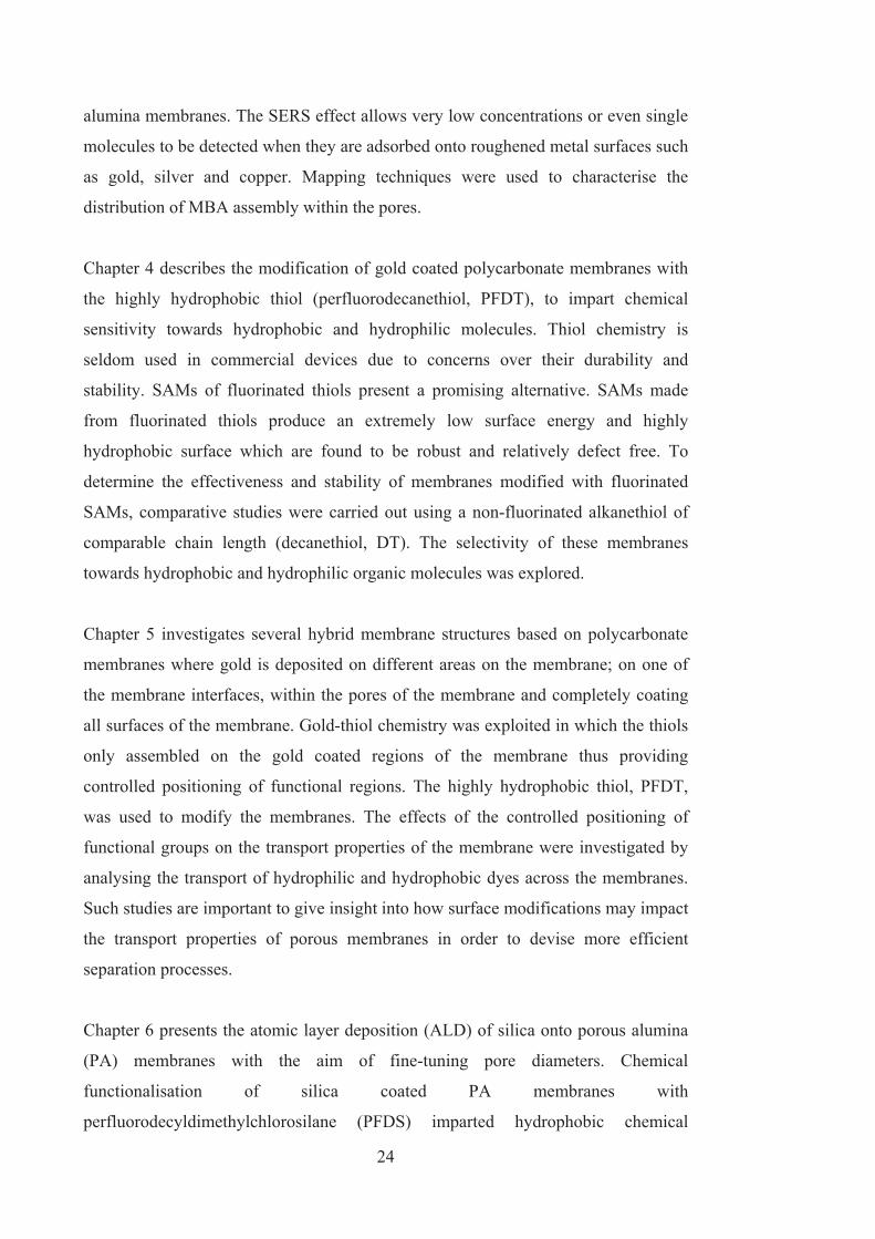
24
alumina membranes. The SERS effect allows very low concentrations or even single
molecules to be detected when they are adsorbed onto roughened metal surfaces such
as gold, silver and copper. Mapping techniques were used to characterise the
distribution of MBA assembly within the pores.
Chapter 4 describes the modification of gold coated polycarbonate membranes with
the highly hydrophobic thiol (perfluorodecanethiol, PFDT), to impart chemical
sensitivity towards hydrophobic and hydrophilic molecules. Thiol chemistry is
seldom used in commercial devices due to concerns over their durability and
stability. SAMs of fluorinated thiols present a promising alternative. SAMs made
from fluorinated thiols produce an extremely low surface energy and highly
hydrophobic surface which are found to be robust and relatively defect free. To
determine the effectiveness and stability of membranes modified with fluorinated
SAMs, comparative studies were carried out using a non-fluorinated alkanethiol of
comparable chain length (decanethiol, DT). The selectivity of these membranes
towards hydrophobic and hydrophilic organic molecules was explored.
Chapter 5 investigates several hybrid membrane structures based on polycarbonate
membranes where gold is deposited on different areas on the membrane; on one of
the membrane interfaces, within the pores of the membrane and completely coating
all surfaces of the membrane. Gold-thiol chemistry was exploited in which the thiols
only assembled on the gold coated regions of the membrane thus providing
controlled positioning of functional regions. The highly hydrophobic thiol, PFDT,
was used to modify the membranes. The effects of the controlled positioning of
functional groups on the transport properties of the membrane were investigated by
analysing the transport of hydrophilic and hydrophobic dyes across the membranes.
Such studies are important to give insight into how surface modifications may impact
the transport properties of porous membranes in order to devise more efficient
separation processes.
Chapter 6 presents the atomic layer deposition (ALD) of silica onto porous alumina
(PA) membranes with the aim of fine-tuning pore diameters. Chemical
functionalisation of silica coated PA membranes with
perfluorodecyldimethylchlorosilane (PFDS) imparted hydrophobic chemical

25
selectivity to the silica modified PA membranes. The transport properties and
selectivity of PFDS modified silica-PA membranes towards hydrophobic and
hydrophilic organic molecules was explored.
Chapter 7 characterises the selective onset of forward osmosis across silica modified
alumina membranes. In this study we observe the onset of forward osmosis only
when particular solutes are used in the draw solution. A set of dyes of differing size,
charge and hydrophobicity were used as draw solutes in order to investigate the
effects of draw solution solute on the water transport ability. The possible
mechanisms behind this discriminatory water transport were explored.
Chapter 8 presents a switchable separation process developed using stimuli
responsive surface modifications. The transport properties of gold coated PA
membranes were controlled through the reversible switching of adsorbed fluorinated
azobenzene layers. A conformational change occurs in the azobenzene unit when
illuminated with UV or visible light. Depending on the wavelength of irradiation, the
molecule can switch between its trans and cis state. A transition to the cis state
essentially buries the end functionality of the assembled molecule. The azobenzene
used in this study contains a hydrophobic fluorinated end group and hence produces
a transition between hydrophobic and less hydrophobic surface properties when
photoisomerisation from the trans to the cis state occurs. The photoresponsive
characteristics of these azobenzene modified membranes were examined through the
switchable transport of a hydrophilic probe dye across the membrane.
Chapter 9 presents concluding remarks and the future direction for novel membrane
development based on the approaches explored in this thesis.

26
1.9. REFERENCES
1. Jirage, K.B., Hulteen, J.C., and Martin, C.R., Effect of thiol chemisorption on
the transport properties of gold nanotubule membranes. Analytical
Chemistry, 1999. 71(21): p. 4913-4918.
2. Jirage, K.B., Hulteen, J.C., Martin, C.R., Nanotubule-Based Molecular-
Filtration Membranes. Science, 1997. 278: p. 655-658.
3. Han, J.Y., Fu, J.P., and Schoch, R.B., Molecular sieving using nanofilters:
Past, present and future. Lab on a Chip, 2008. 8(1): p. 23-33.
4. Kleps, I., Miu, M., Simion, M., Ignat, T., Bragaru, A., Craciunoiu, F., and
Danila, M., Study of the Micro- and Nanostructured Silicon for Biosensing
and Medical Applications. Journal of Biomedical Nanotechnology, 2009.
5(3): p. 300-309.
5. Adiga, S.P., Curtiss, L.A., Elam, J.W., Pellin, M.J., Shih, C.C., Shih, C.M.,
Lin, S.J., Su, Y.Y., Gittard, S.A., Zhang, J., and Narayan, R.J., Nanoporous
materials for biomedical devices. Jom, 2008. 60(3): p. 26-32.
6. Losic, D. and Simovic, S., Self-ordered nanopore and nanotube platforms for
drug delivery applications. Expert Opinion on Drug Delivery, 2009. 6(12): p.
1363-1381.
7. Hillebrenner, H., Buyukserin, F., Stewart, J.D., and Martin, C.R., Template
synthesized nanotubes for biomedical delivery applications. Nanomedicine,
2006. 1(1): p. 39-50.
8. Vandevivere, P.C., Bianchi, R., and Verstraete, W., Treatment and reuse of
wastewater from the textile wet-processing industry: Review of emerging
technologies. Journal of Chemical Technology and Biotechnology, 1998.
72(4): p. 289-302.
9. Duke, M.C., Mee, S., and da Costa, J.C.D., Performance of porous inorganic
membranes in non-osmotic desalination. Water Research, 2007. 41(17): p.
3998-4004.
10. Shannon, M.A., Bohn, P.W., Elimelech, M., Georgiadis, J.G., Marinas, B.J.,
and Mayes, A.M., Science and technology for water purification in the
coming decades. Nature, 2008. 452(7185): p. 301-310.

27
11. Velleman, L., Shapter, J.G., and Losic, D., Gold nanotube membranes
functionalised with fluorinated thiols for selective molecular transport.
Journal of Membrane Science, 2008. 328: p. 121-126.
12. Velleman, L., Shearer, C.J., Ellis, A.V., Losic, D., Voelcker, N.H., and
Shapter, J.G., Fabrication of self-supporting porous silicon membranes and
tuning transport properties by surface functionalization. Nanoscale, 2010.
2(9): p. 1756-1761.
13. Yang, B. and Yang, W.T., Novel pore-covering membrane as a full
open/close valve. Journal of Membrane Science, 2005. 258(1-2): p. 133-139.
14. Martin, C.R., Nishizawa, M., Jirage, K., Kang, M.S., and Lee, S.B.,
Controlling ion-transport selectivity in gold nanotubule membranes.
Advanced Materials, 2001. 13(18): p. 1351-1362.
15. Nishizawa, M., Menon, V.P., and Martin, C.R., Metal Nanotubule
Membranes with Electrochemically Switchable Ion-Transport Selectivity.
Science, 1995. 268: p. 700-702.
16. Casasus, R., Marcos, M.D., Martinez-Manez, R., Ros-Lis, J.V., Soto, J.,
Villaescusa, L.A., Amoros, P., Beltran, D., Guillem, C., and Latorre, J.,
Toward the development of ionically controlled nanoscopic molecular gates.
Journal of the American Chemical Society, 2004. 126(28): p. 8612-8613.
17. Critchley, K., Jeyadevan, J.P., Fukushima, H., Ishida, M., Shimoda, T.,
Bushby, R.J., and Evans, S.D., A mild photoactivated
hydrophilic/hydrophobic switch. Langmuir, 2005. 21(10): p. 4554-4561.
18. Lim, H.S., Han, J.T., Kwak, D., Jin, M.H., and Cho, K., Photoreversibly
switchable superhydrophobic surface with erasable and rewritable pattern.
Journal of the American Chemical Society, 2006. 128(45): p. 14458-14459.
19. Lee, S.B. and Martin, C.R., pH-switchable, ion-permselective gold
nanotubule membrane based on chemisorbed cysteine. Analytical Chemistry,
2001. 73(4): p. 768-775.
20. Liu, D.B., Xie, Y.Y., Shao, H.W., and Jiang, X.Y., Using Azobenzene-
Embedded Self-Assembled Monolayers To Photochemically Control Cell
Adhesion Reversibly. Angewandte Chemie-International Edition, 2009.
48(24): p. 4406-4408.

28
21. Liu, Y., Mu, L., Liu, B.H., Zhang, S., Yang, P.Y., and Kong, J.L., Controlled
protein assembly on a switchable surface. Chemical Communications,
2004(10): p. 1194-1195.
22. Mu, L., Liu, Y., Zhang, S., Liu, B.H., and Kong, J., Selective assembly of
specifically charged proteins on an electrochemically switched surface. New
Journal of Chemistry, 2005. 29(6): p. 847-852.
23. Zareie, H.M., Boyer, C., Bulmus, V., Nateghi, E., and Davis, T.P.,
Temperature-responsive self-assembled monolayers of oligo(ethylene glycol):
Control of biomolecular recognition. Acs Nano, 2008. 2(4): p. 757-765.
24. Schneider, J.J. and Engstler, J., Carbon and polymer filaments in nanoporous
alumina. European Journal of Inorganic Chemistry, 2006(9): p. 1723-1736.
25. Yamaguchi, A., Uejo, F., Yoda, T., Uchida, T., Tanamura, Y., Yamashita, T.,
and Teramae, N., Self-assembly of a silica–surfactant nanocomposite in a
porous alumina membrane. nature materials, 2004. 3: p. 337-341.
26. Steinhart, M., Wehrspohn, R.B., Gosele, U., and Wendorff, J.H., Nanotubes
by Template Wetting: A Modular Assembly System. Angewandte Chemie-
International Edition, 2004. 43: p. 1334 – 1344.
27. Martin, C.R. and Kohli, P., The emerging field of nanotube biotechnology.
Nature Reviews Drug Discovery, 2003. 2(1): p. 29-37.
28. De Leo, M., Pereira, F.C., Moretto, L.M., Scopece, P., Polizzi, S., and Ugo,
P., Towards a better understanding of gold electroless deposition in track-
etched templates. Chemistry of Materials, 2007. 19(24): p. 5955-5964.
29. Menon, V.P., and Martin, C.R., Fabrication and Evaluation of Nanoelectrode
Ensembles. Analytical Chemistry, 1995. 67: p. 1920- 1928.
30. Wirtz, M., Parker, M., Kobayashi, Y., and Martin, C.R., Template-
synthesized nanotubes for chemical separations and analysis. Chemistry-a
European Journal, 2002. 8(16): p. 3573-3578.
31. Gyurcsanyi, R.E., Vigassy, T., and Pretsch, E., Biorecognition-modulated ion
fluxes through functionalized gold nanotubules as a novel label-free
biosensing approach. Chemical Communications, 2003(20): p. 2560-2561.
32. Lee, S.B., and Martin, C.R., Electromodulated Molecular Transport in Gold-
Nanotube Membranes. Journal of the American Chemical Society, 2002. 124:
p. 11850-11851.

29
33. Kobayashi, Y. and Martin, C.R., Highly sensitive methods for
electroanalytical chemistry based on nanotubule membranes. Analytical
Chemistry, 1999. 71(17): p. 3665-3672.
34. Chun, K.Y., and Stroeve, P., Protein Transport in Nanoporous Membranes
Modified with Self-Assembled Monolayers of Functionalized Thiols.
Langmuir, 2002. 18: p. 4653-4658.
35. Hou, Z., Abbott, N.L., and Stroeve, P., Self-Assembled Monolayers on
Electroless Gold Impart pH-Responsive Transport of Ions in Porous
Membranes. Langmuir, 2000. 16: p. 2401-2404.
36. Kohli, P., Wirtz, M., and Martin, C.R., Nanotube membrane based
biosensors. Electroanalysis, 2004. 16(1-2): p. 9-18.
37. Huang, S.S., Sheng, C., Yin, Z.F., Shen, J., Li, R.N., and Peng, B.,
Immunoreaction-based separation of antibodies using gold nanotubules
membrane. Journal of Membrane Science, 2007. 305(1-2): p. 257-262.
38. Hatori, H., Takagi, H., and Yamada, Y., Gas separation properties of
molecular sieving carbon membranes with nanopore channels. Carbon, 2004.
42(5-6): p. 1169-1173.
39. Ritchie, S.M.C., Kissick, K.E., Bachas, L.G., Sikdar, S.K., Parikh, C., and
Bhattacharyya, D., Polycysteine and other polyamino acid functionalized
microfiltration membranes for heavy metal capture. Environmental Science
& Technology, 2001. 35(15): p. 3252-3258.
40. Yamashita, T., Kodama, S., Ohto, M., Nakayama, E., Hasegawa, S.,
Takayanagi, N., Kemmei, T., Yamaguchi, A., Teramae, N., and Saito, Y.,
Permeation flux of organic molecules through silica-surfactant nanochannels
in a porous alumina membrane. Analytical Sciences, 2006. 22(12): p. 1495-
1500.
41. Jeon, G., Yang, S.Y., Byun, J., and Kim, J.K., Electrically Actuatable Smart
Nanoporous Membrane for Pulsatile Drug Release. Nanoletters, 2011.
42. Baker, L.A., Jin, P., and Martin, C.R., Biomaterials and biotechnologies
based on nanotube membranes. Critical Reviews in Solid State and Materials
Sciences, 2005. 30(4): p. 183-205.
43. Yu, S.F., Lee, S.B., Kang, M., and Martin, C.R., Size-based protein
separations in poly(ethylene glycol)-derivatized gold nanotubule membranes.
Nano Letters, 2001. 1(9): p. 495-498.

30
44. de Lint, W.B.S., Biesheuvel, P.M., and Verweij, H., Application of the charge
regulation model to transport of ions through hydrophilic membranes: One-
dimensional transport model for narrow pores (nanofiltration). Journal of
Colloid and Interface Science, 2002. 251(1): p. 131-142.
45. Miller, S.A., Young, V.Y., and Martin, C.R., Electroosmotic flow in
template-prepared carbon nanotube membranes. Journal of the American
Chemical Society, 2001. 123(49): p. 12335-12342.
46. Yuan, H., Cheow, P.S., Ong, J., and Toh, C.S., Characterization of the
electrophoretic mobility of gold nanoparticles with different sizes using the
nanoporous alumina membrane system. Sensors and Actuators B-Chemical,
2008. 134(1): p. 127-132.
47. Wang, S.N.A., Hua, X., and Lee, L.J., Electrokinetics induced asymmetric
transport in polymeric nanonozzles. Lab on a Chip, 2008. 8(4): p. 573-581.
48. Drioli, E. and Giorno, L., Membrane Operations: Innovative Separations and
Transformations. 2009: Wiley-VCH.
49. Baker, R., Membrane Technology and Applications. 2004: Wiley.
50. Rao, S.M. and Zydney, A.L., High resolution protein separations using
affinity ultrafiltration with small charged ligands. Journal of Membrane
Science, 2006. 280(1-2): p. 781-789.
51. Fissell, W.H., Fleischman, A.J., Humes, H.D., and Roy, S., Development of
continuous implantable renal replacement: past and future. Translational
Research, 2007. 150(6): p. 327-336.
52. Thombre, A.G., Cardinal, J.R., DeNoto, A.R., and Gibbes, D.C., Asymmetric
membrane capsules for osmotic drug delivery - II. In vitro and in vivo drug
release performance. Journal of Controlled Release, 1999. 57(1): p. 65-73.
53. Sun, W., Puzas, J.E., Sheu, T.J., Liu, X., and Fauchet, P.M., Nano- to
microscale porous silicon as a cell interface for bone-tissue engineering.
Advanced Materials, 2007. 19(7): p. 921-+.
54. Fissell, W.H., Humes, H.D., Fleischman, A.J., and Roy, S., Dialysis and
nanotechnology: Now, 10 years, or never? Blood Purification, 2007. 25(1): p.
12-17.
55. Motomura, T., Maeda, T., Kawahito, S., Matsui, T., Ichikawa, S., Ishitoya,
H., Kawamura, M., Nishimura, I., Shinohara, T., Oestmann, D., Glueck, J.,
Kawaguchi, Y., Sato, K., and Nose, Y., Extracorporeal membrane

31
oxygenator compatible with centrifugal blood pumps. Artificial Organs, 2002.
26(11): p. 952-958.
56. Lewinska, D., Piatkiewicz, W., and Rosinski, S., Pectin coated hollow fiber
polypropylene membranes. International Journal of Artificial Organs, 1997.
20(11): p. 650-655.
57. Borra, M., Galavotti, D., Bellini, C., Fumi, L., Morsiani, E., and Bellini, G.,
Advanced technology for extracorporeal liver support system devices.
International Journal of Artificial Organs, 2002. 25(10): p. 939-949.
58. Swan, E.E.L., Popat, K.C., and Desai, T.A., Peptide-immobilized nanoporous
alumina membranes for enhanced osteoblast adhesion. Biomaterials, 2005.
26(14): p. 1969-1976.
59. Lu, G.Q. and Zhao, X.S., Nanoporous Materials: Science and Engineering.
Series on Chemical Engineering. Vol. 4. 2004: Imperial College Press.
60. Frisch, H.L. and Mark, J.E., Nanocomposites prepared by threading polymer
chains through zeolites, mesoporous silica, or silica nanotubes. Chemistry of
Materials, 1996. 8(8): p. 1735-1738.
61. Sasaki, T., Nagaoka, S., Tezuka, T., Suzuki, Y., Iwaki, M., and Kawakami,
H., Preparation of novel organic-inorganic nanoporous membranes. Polym.
Adv. Technol., 2005. 16: p. 698–701.
62. Fick, A., Poggendorff’s Annel. Physik, 1855. 94: p. 59-86.
63. Cussler, E.L., Diffusion: Mass transfer in fluid systems. Third Edition ed.
2009: Cambridge University Press.
64. Wijmans, J.G. and Baker, R.W., The solution-diffusion model - a review.
Journal of Membrane Science, 1995. 107(1-2): p. 1-21.
65. Goodman, S.R., Medical Cell Biology. 3rd ed. 2008: Academic Press.
66. Johnson, L.R., Essential medical physiology. Third Edition ed. 2003:
Elsevier.
67. Ulbricht, M., Advanced functional polymer membranes. Polymer, 2006. 47:
p. 2217–2262.
68. Tsuru, T., Nano/subnano-tuning of porous ceramic membranes for molecular
separation. Journal of Sol-Gel Science and Technology, 2008. 46(3): p. 349-
361.
69. Whatman. Nuclepore membranes: Typical data. 2007.

32
70. Orelovich, O.L., and Apel, P.Y., Methods for Preparing Samples of Track
Membranes for Scanning Electron Microscopy. Instruments and
Experimental Techniques, 2001. 44(1): p. 111-114.
71. Apel, P.Y., Blonskaya, I.V., Dmitriev, S.N., Orelovitch, O.L., and Sartowska,
B., Structure of polycarbonate track-etch membranes: Origin of the
“paradoxical” pore shape. Journal of Membrane Science, 2006. 282: p. 393–
400.
72. Gilliam, R.J., Thorpe, S.J., and Kirk, D.W., A nucleation and growth study of
gold nanowires and nanotubes in polymeric membranes. Journal of Applied
Electrochemistry, 2007. 37(2): p. 233-239.
73. Shao, P., Ji, G., and Chen, P., Gold nanotube membranes: Preparation,
characterization and application for enantioseparation. Journal of Membrane
Science, 2005. 255: p. 1–11.
74. Losic, D. and Lillo, M., Porous Alumina with Shaped Pore Geometries and
Complex Pore Architectures Fabricated by Cyclic Anodization. Small, 2009.
5(12): p. 1392-1397.
75. Kirchner, A., MacKenzie, K.J.D., Brown, I.W.M., Kemmitt, T., and Bowden,
M.E., Structural characterisation of heat-treated anodic alumina membranes
prepared using a simplified fabrication process. Journal of Membrane
Science, 2007. 287(2): p. 264-270.
76. Velleman, L., Triani, G., Evans, P.J., Shapter, J.G., and Losic, D., Structural
and chemical modification of porous alumina membranes. Microporous and
Mesoporous Materials, 2009. 126(1-2): p. 87-94.
77. Kohli, P., Wharton, J.E., Braide, O., and Martin, C.R., Template synthesis of
gold nanotubes in an anodic alumina membrane. Journal of Nanoscience and
Nanotechnology, 2004. 4(6): p. 605-610.
78. Bogart, T.E., Dey, S., Lew, K.K., Mohney, S.E., and Redwing, J.M.,
Diameter-controlled synthesis of silicon nanowires using nanoporous
alumina membranes. Advanced Materials, 2005. 17(1): p. 114-+.
79. Rahman, S. and Yang, H., Nanopillar arrays of glassy carbon by anodic
aluminum oxide nanoporous templates. Nano Letters, 2003. 3(4): p. 439-442.
80. Ding, G.Q., Zheng, M.J., Xu, W.L., and Shen, W.Z., Fabrication of
controllable free-standing ultrathin porous alumina membranes.
Nanotechnology, 2005. 16(8): p. 1285-1289.

33
81. Diggle, J.W., Downie, T.C., and Goulding, C.W., Anodic oxide films on
Aluminium. Chemical Reviews, 1969. 69: p. 365.
82. Thompson, G.E., Porous anodic alumina: Fabrication, characterization and
applications. Thin Solid Films, 1997. 297(1-2): p. 192-201.
83. Masuda, H. and Fukuda, K., Ordered metal nanohole arrays made by a 2-
step replication of honeycomb structures of anodic alumina. Science, 1995.
268(5216): p. 1466-1468.
84. Huczko, A., Template-based synthesis of nanomaterials. Applied Physics a-
Materials Science & Processing, 2000. 70(4): p. 365-376.
85. Love, J.C., Estroff, L.A., Kriebel, J.K., Nuzzo, R.G., and Whitesides, G.M.,
Self-assembled monolayers of thiolates on metals as a form of
nanotechnology. Chemical Reviews, 2005. 105(4): p. 1103-1169.
86. Blake, P., Ahn, W., and Roper, D.K., Enhanced Uniformity in Arrays of
Electroless Plated Spherical Gold Nanoparticles Using Tin Presensitization.
Langmuir, 2010. 26(3): p. 1533-1538.
87. Kobayashi, Y., Tadaki, Y., Nagao, D., and Konno, M., Deposition of gold
nanoparticles on silica spheres by electroless metal plating technique.
Journal of Colloid and Interface Science, 2005. 283(2): p. 601-604.
88. Sanchez-Castillo, M.A., Couto, C., Kim, W.B., and Dumesic, J.A., Gold-
nanotube membranes for the oxidation of CO at gas-water interfaces.
Angewandte Chemie-International Edition, 2004. 43(9): p. 1140-1142.
89. De Leo, M., Kuhn, A., and Ugo, P., 3D-ensembles of gold nanowires:
Preparation, characterization and electroanalytical peculiarities.
Electroanalysis, 2007. 19(2-3): p. 227-236.
90. Pereira, F.C., Moretto, L.M., De Leo, M., Zanoni, M.V.B., and Ugo, P., Gold
nanoelectrode ensembles for direct trace electroanalysis of iodide. Analytica
Chimica Acta, 2006. 575(1): p. 16-24.
91. Demoustier-Champagne, S., and Delvaux, M., Preparation of polymeric and
metallic nanostructures using a template-based deposition method. Materials
Science and Engineering C, 2001. 15: p. 269–271.
92. Hulteen, J.C., Jirage, K.B., and Martin, C.R., Introducing Chemical
Transport Selectivity into Gold Nanotubule Membranes. Journal of the
American Chemical Society, 1998. 120: p. 6603-6604.

34
93. Majumder, M., Chopra, N., and Hinds, B.J., Effect of tip functionalization on
transport through vertically oriented carbon nanotube membranes. Journal of
the American Chemical Society, 2005. 127(25): p. 9062-9070.
94. Ulbricht, M., Matuschewski, H., Oechel, A., and Hicke, H.G., Photo-induced
graft polymerization surface modifications for the preparation of hydrophilic
and low-protein-adsorbing ultrafiltration membranes. Journal of Membrane
Science, 1996. 115(1): p. 31-47.
95. Popat, K.C., Mor, G., Grimes, C.A., and Desai, T.A., Surface modification of
nanoporous alumina surfaces with poly(ethylene glycol). Langmuir, 2004.
20(19): p. 8035-8041.
96. Sagle, A.C., Van Wagner, E.M., Ju, H., McCloskey, B.D., Freeman, B.D.,
and Sharma, M.M., PEG-coated reverse osmosis membranes: Desalination
properties and fouling resistance. Journal of Membrane Science, 2009.
340(1-2): p. 92-108.
97. Bain, C.D., Biebuyck, H.A., and Whitesides, G.M., Comparison of Self -
Assembled Monolayers on Gold: Coadsorption of Thiols and Disulfides.
Langmuir, 1989. 5: p. 723-727.
98. Bain, C.D., Troughton, E.B., Tao, Y-T., Whitesides, G.M., and Nuzzo, R.G.,
Formation of Monolayer Films by the Spontaneous Assembly of Organic
Thiols from Solution onto Gold. Journal of the American Chemical Society,
1989. 111: p. 321-335.
99. Chechik, V. and Stirling, C., Gold-thiol self-assembled monolayers, in The
chemistry of organic derivatives of gold and silver, S. Patai and Z.
Rappoport, Editors. 1999, John Wiley & Sons Ltd.
100. Martin, C.R., Nishizawa, M., Jirage, K., and Kang, M., Investigations of the
Transport Properties of Gold Nanotubule Membranes. Journal of Physical
Chemistry B, 2001. 105: p. 1925-1934.
101. Chun, K.Y., and Stroeve, P., External Control of Ion Transport in
Nanoporous Membranes with Surfaces Modified with Self-Assembled
Monolayers. Langmuir, 2001. 17: p. 5271-5275.
102. Browne, W.R. and Feringa, B.L., Light Switching of Molecules on Surfaces.
Annual Review of Physical Chemistry, 2009. 60: p. 407-428.

35
103. Mu, L., Liu, Y., Cai, S.Y., and Kong, J.L., A smart surface in a microfluidic
chip for controlled protein separation. Chemistry-a European Journal, 2007.
13(18): p. 5113-5120.
104. Schmuhl, R., van den Berg, A., Blank, D.H.A., and ten Elshof, J.E.,
Surfactant-modulated switching of molecular transport in nanometer-sized
pores of membrane gates. Angewandte Chemie-International Edition, 2006.
45(20): p. 3341-3345.
105. Liu, Y.L., Zhao, M.Q., Bergbreiter, D.E., and Crooks, R.M., pH-switchable,
ultrathin permselective membranes prepared from multilayer polymer
composites. Journal of the American Chemical Society, 1997. 119(37): p.
8720-8721.
106. Ku, J.R., Lai, S.M., Ileri, N., Ramirez, P., Mafe, S., and Stroeve, P., pH and
ionic strength effects on amino acid transport through Au-nanotubule
membranes charged with self-assembled monolayers. Journal of Physical
Chemistry C, 2007. 111(7): p. 2965-2973.
107. Ulbricht, M., Ozdemir, S., and Geismann, C., Functionalized track-etched
membranes as versatile tool to investigate stimuli-responsive polymers for
"smart" nano- and microsystems. Desalination, 2006. 199(1-3): p. 150-152.
108. Tokarev, I., Gopishetty, V., Zhou, J., Pita, M., Motornov, M., Katz, E., and
Minko, S., Stimuli-Responsive Hydrogel Membranes Coupled with
Biocatalytic Processes. Acs Applied Materials & Interfaces, 2009. 1(3): p.
532-536.
109. Yoshida, M., Nagaoka, N., Asano, M., Omichi, H., Kubota, H., Ogura, K.,
Vetter, J., Spohr, R., and Katakai, R., Reversible on-off switch function of ion-
track pores for thermo-responsive films based on copolymers consisting of
diethyleneglycol-bis-allylcarbonate and acryloyl-L-proline methyl ester.
Nuclear Instruments & Methods in Physics Research Section B-Beam
Interactions with Materials and Atoms, 1997. 122(1): p. 39-44.
110. Wang, W.C., Tian, X.D., Feng, Y.P., Cao, B., Yang, W.T., and Zhang, L.Q.,
Thermally On-Off Switching Membranes Prepared by Pore-Filling Poly(N-
isopropylacrylamide) Hydrogels. Industrial & Engineering Chemistry
Research, 2010. 49(4): p. 1684-1690.
111. Abidian, M.R., Kim, D.H., and Martin, D.C., Conducting-polymer nanotubes
for controlled drug release. Advanced Materials, 2006. 18(4): p. 405-+.

36
112. Fletcher, B.L., Retterer, S.T., McKnight, T.E., Melechko, A.V., Fowlkes,
J.D., Simpson, M.L., and Doktycz, M.J., Actuatable membranes based on
polypyrrole-coated vertically aligned carbon nanofibers. Acs Nano, 2008.
2(2): p. 247-254.

CHAPTER 2 EXPERIMENTAL DETAILS
2. Chapter 2

38
2.1. MEMBRANE FABRICATION
2.1.1. Fabrication of porous alumina (PA) membranes
Aluminium foil (99.997 %, Alfa Aesar, USA) was cleaned in acetone with the aid of
sonication. Two-step anodisation was performed (Figure 2-1) using an
electrochemical cell equipped with a cooling stage set to a temperature of 1 oC. The
first anodisation step was performed at 60 - 80 V for 5-10 min in 0.3 M oxalic acid.
Afterwards, the formed porous oxide film was chemically removed using a mixture
of 6 wt% of H3PO4 and 1.8% chromic acid for a minimum of 3 h at 75 oC. A second
anodisation was performed at 80 V for 15 min in 0.3 M oxalic acid (-1 oC) to achieve
PA membranes with thicknesses of 20 – 30 m. The aluminium was then removed
by immersion in a CuCl2/HCl solution leaving the PA membrane behind. The barrier
oxide layer at the bottom face of the membrane was removed by immersion in 10
wt% H3PO4 for 3 h. This process opens the pores to create open channels in the
membrane. During the barrier oxide removal, the top face of the PA membrane was
protected by masking with nail polish. After pore opening the nail polish was
removed by rinsing with copious amounts of acetone.
2.1.2. Fabrication of gold nanotube membranes
Electroless deposition onto polycarbonate membranes The procedure for
synthesising gold nanotube membranes by electroless gold deposition within porous
templates has been previously described by Martin et al. [1]. Firstly, the membranes
were immersed in methanol for 30 min to ensure complete wetting. In the first step,
referred to as sensitisation, the membrane was immersed in a solution of 0.026 M
SnCl2 and 0.07 M trifluoroacetic acid (Sigma-Aldrich) in a solvent of 50:50
methanol:water for 45 min followed by rinsing in methanol for 5 min. This was
followed by the second step, referred to as activation, where the membrane was
immersed in a solution of 0.029 M ammoniacal AgNO3 for 7.5 min. This solution
was prepared by the dropwise addition of ammonium hydroxide to an aqueous
solution of AgNO3 (Proscitech, Australia) which turned turbid brown and was
stopped once the solution turned clear. The membrane was then rinsed in methanol

39
for 5 min and immersed in water before placing the membranes in the gold
deposition bath. In the third step, referred to as displacement
Figure 2-1 Cross sectional schematic of porous alumina fabrication.
deposition, the Ag coated membrane was immersed in the gold deposition solution
consisting of 0.079 M Na3Au(SO3)2 (Oromerse, Technic Inc. USA), 0.127 M
Na2SO3, 0.625 M formaldehyde and 0.025 M NaHCO3. The temperature of this bath

40
was ~ 1 - 4 oC with a pH of 8. The pH was adjusted to 8 through the drop wise
addition of 1.8 M H2SO4. Gold deposition was allowed to proceed until the desired
pore size was obtained. After gold deposition, the membrane was thoroughly rinsed
in water and immersed in 25 % HNO3 for at least 12 h to remove any residual Sn or
Ag followed by rinsing in water and air-drying. The samples were flattened between
glass slides and heat treated at 160 oC for 30 min then left to cool to room
temperature.
2.1.2.1. Electroless deposition onto porous alumina membranes
The electroless deposition procedure for porous alumina is similar to that of
polycarbonate with a few alterations. Firstly the porous alumina must be
hydroxylated in order to allow for the chelation of tin onto the surface. This is
achieved through boiling PA in hydrogen peroxide for 30 min. The membrane is then
immersed in hot water for 15 min before placing in the tin sensitisation solution. The
tin, silver and gold deposition steps proceed as usual. After gold deposition is
completed the membranes are not exposed to nitric acid treatment as this will
dissolve the membrane, instead the membranes are only rinsed in water and air-dried.
2.1.3. Fabrication of silica modified porous alumina membranes via
atomic layer deposition
Commercial porous alumina membranes were used (Whatman Anodisc, UK) with
pore diameters quoted as 20, 100 and 200 nm. The atomic layer deposition (ALD)
precursors, tris(tert-butoxy)silanol (t-BuO)2SiOH, 99.999% purity) and trimethyl
aluminium (TMA, (99.9% purity)) were supplied by Sigma–Aldrich. Prior to ALD,
membranes were repeatedly washed in ethanol followed by Milli Q water and dried
with a nitrogen jet. ALD was carried out in a viscous flow-type reactor (ASM
Microchemistry, F - 120) by collaborators from ANSTO, Sydney. To deposit SiO2 by
ALD the PA membranes were exposed to tri(tert-butoxy)silanol, and TMA as the
precursor couple [2]. Clean PA membranes with different pore sizes (20, 100 and
200 nm), with the top side facing the flow of precursors, were placed in the chamber.
The precursors were carried to the membrane by a flow of nitrogen gas, which was
also used to purge the reactor between precursor pulses. The temperature of

41
deposition was 225 oC. The sequential pulse and purge regime was 1s/1s/5s/5s for
the particular reaction sequence TMA/purge/(t-BuO)2- SiOH/purge. SiO2 thin-films
were grown at 3, 5, 7, 10, 15 and 20 cycles in order to obtain conformal coatings
with different thicknesses on the PA pores and hence reduce pore diameters. Silicon
wafers were also coated with SiO2 for reference purposes and the thicknesses of the
deposited silica films were determined by spectroscopic ellipsometry (SOPRA
GES5E). A growth rate of 2.5 – 3 nm/cycle was determined for the ALD process.
2.2. SURFACE FUNCTIONALISATION OF MEMBRANES
2.2.1. Thiol functionalisation of gold coated membranes
The thiol molecules; (1-decanethiol, 1H,1H,2H,2H-perfluorodecanethiol and
cysteamine) were purchased from Sigma-Aldrich (Australia) and were used to create
SAMs on the surfaces of the gold nanotube membranes. Prior to self assembly, the
membrane was thoroughly rinsed in ethanol. The membranes were functionalised by
immersion in a 3 mM solution of the thiol in ethanol for 24 h under nitrogen
atmosphere, followed by rinsing in ethanol and water. The functionalised membranes
were then stored in ethanol.
2.2.2. Functionalisation of silica modified alumina membranes
The surfaces of the SiO2-PA membranes were hydroxylated under water plasma at a
pressure of 0.2 atm for 1 min. The water plasma process forms OH groups over both
SiO2 and alumina surfaces [3-4]. The samples were then functionalised with the
hydrophobic silane, perfluorodecyldimethylchlorosilane (PFDS, Gelest Inc.) by
immersion in a 0.1 v % solution of the silane in dry toluene for 2 h under nitrogen
atmosphere [4]. The silane reacts with the OH groups on the Al and Si surfaces to
form a covalently bonded self assembled monolayer. The membrane was then
thoroughly rinsed in dry toluene followed by dry dichloromethane and dried in air.

42
2.3. CHARACTERISATION OF MEMBRANES
2.3.1. Scanning and transmission electron microscopy
2.3.1.1. SEM and TEM of gold coated polycarbonate membranes
Scanning electron microscopy (SEM) and energy dispersive x-ray microscopy
(EDAX) (Philips XL30) was used to characterise the deposition of gold onto the
membranes. The membrane samples were cut into small pieces and mounted on a
holder with double sided conductive tape. If required, the top and bottom gold
surfaces of the membrane were removed by simply wiping the membrane with a
cotton tip immediately after deposition, whilst the membrane was still wet. The gold
nanotubes within the pores were liberated from the template support by immersion
into dichloromethane resulting in a suspension of gold nanotubes. The suspension
was deposited onto porous alumina or porous silicon substrates and rinsed with
excess dichloromethane to ensure entire dissolution of the polycarbonate. For
imaging uncoated polycarbonate membranes the samples were coated with ~ 5 nm of
platinum (Quorumtech K757X sputter coater). Pore size distributions were measured
using Adobe Photoshop CS5.
For transmission electron microscopy (TEM) (Philips CM100) analysis, cross
sections of the gold coated membranes were obtained by microtoming resin
encapsulated gold membranes. These cross sections were affixed onto copper TEM
grids. The liberated gold nanotubes were also viewed via TEM by dropping the
suspension of dichloromethane dissolved nanotubes onto TEM grids and allowing to
air dry.
2.3.1.2. SEM and TEM of gold coated porous alumina membranes
Philips XL30 and the Helios Dualbeam Nanolab 600 scanning electron microscopes
were used to view the porous alumina samples. Cross sections of the gold coated
membranes were obtained by fracturing the membrane. In order to view the gold
nanotubes formed within the pores, the PA template was removed by dissolution in
10 wt% H3PO4. Uncoated PA membranes were coated with 5 nm platinum

43
(Quorumtech K757X sputter coater). Pore size distributions were measured using
Adobe Photoshop CS5.
2.3.1.3. SEM of silica modified alumina membranes
Surface characterisation of PA membranes before and after ALD silica deposition
was performed using a SEM (Philips XL 30). The membrane samples were coated
with a few nanometres of platinum. Images with a range of scan sizes and at normal
incidence and at an angle of 40o were acquired to characterise the pore structures of
silica coated PA membranes. Pore size distributions were determined from SEM
images using image processing software (Image J, NIH, USA).
2.3.2. Dynamic secondary ion mass spectrometry (SIMS) and
ellipsometry characterisation of silica coated PA membranes
Elemental depth profiles of selected ALD coated PA samples were obtained by
dynamic SIMS using a Cameca ims 5f spectrometer by collaborators from ANSTO
(Sydney). A Cs+ primary ion beam was rastered over an area of 50 m x 50 m was
used for depth profiling. Secondary caesium cluster ions (MCs+) from a ~ 15 m
diameter central region of the sputtered crater were detected. Ion beam currents of 2
and 10 nA were used to sputter depth profile the SiO2 surface film. Thickness
measurements of ALD deposited silica films on silicon wafers used as controls were
performed using a high resolution spectroscopic ellipsometer SOPRA GES5E
(France). The measurements were carried out at a specific wavelength of ~ 600 nm
as the angles of incidence and reflected light detection were varied between 40o and
85o. A series of samples fabricated using different deposition times were
characterised to establish the deposition rate.
2.3.3. Electrochemical characterisation of gold nanotube membranes
Electrochemical characterisation of bare and modified gold nanotube membranes
was performed using the electrochemical system CHI 600 (CH Instrument, USA).
Current-voltage curves were recorded versus an Ag/AgCl saturated KCl reference

44
electrode and a Pt mesh auxiliary electrode. Electrochemical measurements were
performed in U-tube permeation cell where the active area of electrode is defined
using an O-ring pressed against the gold membrane. Electrolyte solutions were
purged with argon for at least 30 minutes prior to measurements and blanketed in
argon throughout the experiments. To assess the quality of thiol modified gold
membranes two cyclic voltammetry (CV) measurements were performed using a
redox probe (1 mM potassium ferricyanide), and electrochemical reduction of gold
oxide (0.1 M sulphuric acid) [5-6]. Heterogeneous electron-transfer measurements
for the assessment of the passivating ability of the films were conducted in 1 mM
potassium ferricyanide in 0.2 M KCl. Applied potential windows of -0.5 to +0.8 V
with scan rates between 25 and 200 mVs-1. Electrochemical stripping of gold oxide
was performed in 0.1 M sulphuric acid at potentials of -0.5 to 1.5 V at scan rates of
100 mVs-1. The integrated charge, Q( C cm-2), under the oxide removal peak of the
SAM-modified electrode was used as a measure of the total fractional pinhole area, 1
- (where is the SAM coverage). Stripping was followed by an additional scan in
the same voltage range to verify the total removal of the oxide in the first scan with
the second reduction scan used as basis for calculations. Additionally, repeated
cycling for up to 25 cycles was used as a guide to the robustness of the SAMs on
each substrate.
2.3.4. Contact angle measurements
Effects of surface modifications were investigated using contact angle
measurements. Contact angle experiments were performed with a custom built
measurement system. Samples were affixed to a glass slide and a 1 μL drop of water
was deposited onto the surface of the membrane and the image was captured on a
fixed camera. ImageJ software was used to determine the contact angle of the droplet
on the surface. The mean value of the contact angles was calculated from at least 3
individual measurements taken at different locations on the examined substrates.

45
2.3.5. Raman spectroscopy of 3-mercaptobenzoic acid on gold coated
PA membranes
SERS spectra were recorded with a LabRam II Raman spectrometer (Horiba Jobin-
Yvon) coupled to an Olympus confocal microscope and equipped with a HeNe laser
operating at 632.8 nm as the excitation source (laser power 100 W at sample, 100×
Olympus objective and laser spot diameter 1 m). The acquisition time for each
spectrum was 60 s and the spectral resolution 4 cm-1. A 2 m step size was used for
the line scans.
2.4. INVESTIGATION OF THE TRANSPORT PROPERTIES OF MEMBRANES
2.4.1. Transport experiments
Transport experiments were performed using a home-made U-tube permeation cell in
which the membrane separates two half-cells; the feed cell and the permeate cell
(Figure 2-2). A hole was punched into thin PDMS sheets to act as o-rings between
the membrane and the cell with one sheet placed on either side of the membrane. The
diameter of the hole in the PDMS on the feed side of the membrane presents the
effective area of the membrane exposed to the feed solution. Various dyes were used
to probe the transport properties of the membranes. The structures of the dyes used in
these studies are shown in (Figure 2-3). Separate permeation experiments were
performed in which a 1mM aqueous solution of the dye was added to the feed cell
while pure water was added to the permeate cell. The diffusion of the dye from the
feed cell to the permeate cell was continuously monitored with a UV-Vis fibre optic
spectrophotometer (Ocean Optics, USA, Figure 2-2b) at the maximum peak
absorbance. The peak absorbance was logged (Spectrasuite, Ocean Optics) every 10
s. The flux of the dyes through each of the membranes was calculated by correlating
the maximum absorbance with the concentration of the dye. Concentration
calibration plots were obtained by measuring the peak absorbance for a set of dye
solutions with known concentration.

46
2.4.2. Measurement of dye oil:water partition coefficients
Hydrophobic and hydrophilic probe dyes were chosen for transport experiments
based on their oil:water partition coefficients. Laboratory shake flask experiments
were conducted as according to OECD guideline 107 [7] using n-octanol (Sigma-
Aldrich) and Milli-Q water. The octanol and water were saturated with water and
octanol respectively prior to the experiments and herein reference to octanol and
water refers to their saturated solutions. All dyes were dissolved in water to obtain a
concentration of 1 mM. Octanol and water were added to centrifuge tubes to obtain
an octanol:water ratio of 1:1, 1:2 and 2:1 with a total volume of 8 mL. Each ratio was
carried out in triplicate. The dyes were added to the centrifuge tubes and the phases
were mixed by vortex for 10 min and then centrifuged at 1000 rpm for 10 min. The
water phase was extracted and the concentration in the water phase was determined
via UV-Vis spectroscopy (Ocean Optics system, USA). The dye concentrations were
determined only from the water phase and the concentration of the dyes in the
octanol phase was calculated by subtraction of the concentration in the water phase.

47
Figure 2-2 (a) Schematic and photo of the permeation cell set up used in these studies. (b) Photo of the
Ocean Optics UV-Vis system.

48
Figure 2-3 Structures of probe dye molecules used in the transport experiments.
2.5. SYNTHESIS OF FLUORINATED AZOBENZENE FOR THE DEVELOPMENT OF
SWITCHABLE MEMBRANES
2.5.1. Synthesis of 4-(4-trifluoromethoxyphenylazo)phenol (1)
4-(Trifluoromethoxy)aniline (75 mmol) was added dropwise under heating (~ 60 oC)
to a mixture of 21 ml concentrated sulphuric acid and 21 ml water. This reaction
yields a white foam. After cooling the solution was diazotised by the dropwise
addition of a solution of 7 g sodium nitrite in 40 ml water at 0 ~ 5 oC to the acid
mixture. The solution was stirred for 1 h. The diazotisation solution was slowly
added to a solution of 7.5 g phenol, 3 g sodium hydroxide and 47 g sodium carbonate
in 270 ml water at 0 ~ 5 oC. The yellow coloured precipitate was filtered off, dried
under vacuum and recrystallised from n-hexane (Figure 2-4).

49
2.5.2. Synthesis of 7-[(trifluoromethoxyphenylazo)phenoxy]pentanoic
acid (2)
6-bromohexanoic acid (23.1 mmol) was added to a mixture of 4-(4-trifluoromethoxy
phenylazo)phenol (19.0 mmol) and potassium hydroxide (42.4 mmol) in 150 ml
ethanol and the mixture was refluxed at 70 oC for 20 h. The solution was cooled to
room temperature then the inorganic salts were removed by filtration. The filtrate
was acidified with 40 ml acetic acid, and then refluxed for 30 min. The solvent was
removed in vacuo and 200 ml chloroform was added. The organic layer was washed
three times with water and dried over sodium sulfate. Recrystallisation from
acetonitrile afforded orange crystals (Figure 2-4).
Figure 2-4 Scheme of the synthesis of 4-(4-trifluoromethoxyphenylazo)phenol (1) (intermediary) and
7-[(trifluoromethoxyphenylazo)phenoxy]pentanoic acid (2).

50
2.6. REFERENCES
1. Menon, V.P., and Martin, C.R., Fabrication and Evaluation of Nanoelectrode
Ensembles. Analytical Chemistry, 1995. 67: p. 1920- 1928.
2. Hausmann, D., Becker, J., Wang, S.L., and Gordon, R.G., Rapid vapor
deposition of highly conformal silica nanolaminates. Science, 2002.
298(5592): p. 402-406.
3. Ravoo, B.J., Reinhoudt, D.N., and Onclin, S., Engineering Silicon Oxide
Surfaces Using Self-Assembled Monolayers. Angewandte Chemie-
International Edition, 2005. 44: p. 6282 – 6304.
4. Jani, A.M.M., Anglin, E.J., McInnes, S.J.P., Losic, D., Shapter, J.G., and
Voelcker, N.H., Nanoporous anodic aluminium oxide membranes with
layered surface chemistry. Chemical Communications, 2009(21): p. 3062-
3064.
5. Losic, D., Shapter, J.G., and Gooding, J., Atomically Flat Gold for
Biomolecule Immobilisation and Imaging. Australian Journal of Chemistry,
2001. 54: p. 643-648.
6. Losic, D., Shapter, J.G., and Gooding, J.J., Influence of surface topography
on alkanethiol SAMs assembled from solution and by microcontact printing.
Langmuir, 2001. 17(11): p. 3307-3316.
7. Guideline for the testing of chemicals - partition coefficient (n-
octanol/water): shake flask method. 1995, Paris: OECD Organisation for
Economic Cooperation and Development

CHAPTER 3 RAMAN SPECTROSCOPY OF THIOLS
ADSORBED INSIDE THE PORES OF GOLD-
ALUMINA MEMBRANES The surface enhanced Raman scattering (SERS) effect was employed to confirm and
characterise the formation of SAMs of 3-mercaptobenzoic acid (mMBA) on the
surfaces of the gold coated alumina membranes. The investigation of the coverage
and reproducibility of SAMs within porous matrices is of utmost importance in the
design of filtration membranes and sensing platforms.
3. Chapter 3

52
3.1. INTRODUCTION
Much of the work outlined in this thesis involves the implementation of various gold
coated membranes for the investigation of surface chemistry driven transport
phenomena. Due to their highly ordered structure and ease of surface
functionalisation, gold coated porous alumina (Au-PA) membranes provide an ideal
model for studying the impact of surface chemistry on molecular transport through
membranes. Research into employing surface chemistry to improve transport
selectivity and sensing is relatively recent but is essential for the development of
membrane materials. Through further characterisation of SAMs within membranes
more efficient separation processes can be devised. Consequently it is imperative to
confirm the nature of SAMs within pores in order to elucidate their full impact on the
transport phenomena through membranes. Whilst enormous effort has been made to
investigate and characterise SAMs, the characterisation of SAMs within restricted
spaces such as pores is currently poorly understood and difficult to probe [1].
There are numerous analytical techniques capable of investigating the structure and
formation of SAMs of thiols on gold including XPS, FTIR, Raman and
electrochemistry. Many of these methods are used to study SAMs on planar gold
surfaces providing both qualitative and quantitative information about SAMs [2-3].
In particular, Surface Enhanced Raman Spectroscopy (SERS) is a powerful
analytical tool due to the immense enhancement of the Raman scattering of a
molecule [3]. The SERS effect allows very low concentrations or even single
molecules to be detected when they are adsorbed onto roughened metal surfaces such
as gold, silver and copper [7, 8]. Extensive research has been focussed on the
fabrication of new metal structures for use as SERS substrates for sensing
applications. Recently, metal nanorods, tubes and nanoporous metals have been
exploited as SERS substrates [8-10].
The mechanism of electroless gold deposition is the nucleation and growth of gold
nanoparticles [4]. Since the SERS effect is known to occur for nanoparticles [5] then
electrolessly coated PA membranes can potentially provide a roughened gold surface
suitable for use as a SERS substrate [5, 6]. These gold nanotube membranes have the
potential to develop into SERS active substrates for ultrasensitive sensing

53
technologies. These technologies require reproducible, reusable, stable and tuneable
SERS substrates. Gold coated porous alumina membranes present an extremely
reproducible material due to highly ordered and controlled alumina fabrication and
uniform gold deposition.
The aim of this chapter is to explore the application of the SERS effect to confirm
and characterise the deposition of 3-mercaptobenzoic acid (mMBA) on the interfaces
of a gold coated PA membrane and within the confines of the pores (Figure 3-1). In
addition, Raman spectroscopy is capable of spatially resolved techniques such as
mapping and depth profiling which is used to identify and characterise the
distribution of mMBA assembly along the length of the pores. To our knowledge,
this is the first attempt to characterise SAMs within pores and probe their spatial
distribution using scanning cross-sectional Raman spectroscopy.
Figure 3-1 Schematic of electrolessly gold coated porous alumina membranes and functionalisation of
the gold surfaces with 3-mercaptobenzoic acid.
3.2. EXPERIMENTAL DETAILS
3.2.1. Fabrication of porous alumina membranes
Porous alumina was fabricated as outlined in section 2.1.1. The second anodisation
was performed under 80 V for 15 min in 0.3 M oxalic acid (-1 oC) to achieve PA
with thicknesses of 20 – 30 m. The barrier oxide layer at the bottom face of the
membrane was removed by immersion in 10 wt% H3PO4 for 3 h.

54
3.2.2. Electroless gold deposition
Electroless gold deposition onto porous alumina membranes was carried out as stated
in section 2.1.2.1 with the following adjustments. Prior to tin sensitisation the bottom
face of the membrane was coated with nail polish and dried in air in order to block
gold deposition on this face. The tin and silver deposition steps proceeded as usual.
A gold deposition time of 19 h was used in this study after which the nail polish film
was removed with copious rinsing in acetone then allowed to air-dry.
3.2.3. Thiol functionalisation of gold nanotube membranes
The Au-PA membranes were functionalised with 3-mercaptobenzoic acid (mMBA,
Sigma-Aldrich) by immersion in a 3 mM solution in ethanol for 24 h, followed by
rinsing in ethanol and water then air dried.
3.2.4. Raman spectroscopy of MBA on Au-PA membranes
SERS spectra were obtained as outlined in section 2.3.5. A cross section of the
membrane was obtained by snapping the sample in half and then clamped in a
custom built holder in order to orient the cross section to face the Raman objective.
3.3. RESULTS AND DISCUSSION
3.3.1. Structural characterisation of gold – alumina (Au-PA)
membranes
SEM was used to examine the surface morphology of the Au-PA membranes (Figure
3-2a). The electroless deposition of gold provided a significant reduction in the pore
diameter of the Au-PA membrane in comparison with the uncoated PA membranes.
Pore size measurements of PA templates and Au-PA membranes were calculated
through the analysis of SEM images. The original PA template pore size is 170.0 ±
21.1 nm. After electroless deposition the pore diameter of the Au-PA membranes
have been reduced to 57.0 ± 12.5 nm (Figure 3-2d). In this work, gold deposition
parameters were carefully chosen to provide optimum films. It is well documented
that the gold deposition kinetics can be varied by changing the concentration of gold,

55
pH, and temperature of the gold deposition bath [6-7]. In our case we have reduced
the pH of the gold deposition bath to 8 to decrease the rate of deposition of gold in
order to achieve a more homogenous gold layer in addition to preventing the
dissolution of alumina which occurs at high pH. Figure 3-2b displays an SEM image
of an Au-PA membrane where the surface gold layer has been removed by scratching
off the top layer of gold with a scalpel. The image clearly shows the tips of the gold
nanotubes and presents a clearer indication of the magnitude of the reduction in the
pore diameters due to the increase in the thickness of the gold. The outer diameter of
the gold nanotubes corresponds to the pore diameter of the original PA template.
Figure 3-2c presents an SEM image of the cross section of the Au-PA membrane
after fracturing the membrane. The thickness of the membrane is found to be ~ 21
m.
To confirm that gold deposition occurred inside the pores of the membrane, the
supporting alumina template was dissolved revealing the gold nanotube structures
(Figure 3-3a). A standing array of gold nanotubes is formed supported by the
existing gold layer which was present on the top face of the membrane. Figure 3-3c
presents the EDAX analysis of the nanotubes array confirming their composition of
gold. The tubular shape of the gold is obvious, therefore confirming successful gold
attachment to the pore walls. The length of the gold nanotubes obtained matches the
thickness of the PA template thus signifying that the gold deposition has extended
through the entire thickness of the membrane. Given that one side of the membrane
was completely blocked with nail polish during the gold deposition stages, this
suggests that electroless gold deposition is a reliable technique for coating thick
porous materials. The section of the gold nanotube immediately adjacent to the top
face of the membrane exhibits dense gold packing (Figure 3-3a). However, some
pinholes in the gold nanotubes can be observed which becomes more prevalent in the
nanotube regions of > 5 m depth into the membrane (Figure 3-3b). Therefore
although gold deposition can occur throughout the length of the pore, it appears that
the quality of the gold deposition diminishes slightly at depths greater than 5 m.

56
Figure 3-2. SEM images of a) the surface of an Au-PA membrane and b) an area of the membrane
where the gold surface layer was cleaved exposing the tips of the gold nanotubes formed within the
pores. c) cross section of the Au-PA membrane. d) pore size distribution of Au-PA membranes.

57
Figure 3-3 SEM images of a section of liberated gold nanotubes after dissolution of the porous
alumina from the top of the membrane (a) and from the centre of the membrane (b). EDAX analysis
of the nanotube array confirming their composition of gold (c).

58
3.3.2. Characterisation of SAMs within the pores of Au-PA membranes
by Raman spectroscopy
Figure 3-4 shows the normal Raman spectrum of pure mMBA and the SERS
spectrum of mMBA assembled on the surface of an Au-PA membrane. The SERS
spectrum of mMBA on gold (Figure 3-4b) is dominated by bands at 1570 cm-1, 1130
cm-1 , 1080 cm-1, 1000 cm-1 and 840 cm-1 which involve CC stretching, HCC and
CCC bending vibrations of the benzene ring [8]. The assignments are performed by a
comparison with the Raman spectra of disubstituted benzenes [8-9] and 4-
mercaptobenzoic acid [9-12]. The SERS enhancement is not observed for all
vibrational modes of mMBA and the Raman peaks in the SERS spectrum are
systematically red shifted by 3 – 10 cm-1 in comparison to bulk mMBA (Figure 3-4).
The vibrational shifts are due in part to the charge transfer occurring between the
gold surface and mMBA [10]. The dissociation of the SH group of mMBA at the
gold surface results in formation of a coordinative bond between the gold and the
sulphur moiety, allowing charge transfer between the gold and mMBA.
In bulk mMBA, stretching (SH) bands at about 2600 cm-1 and bending (SH) bands
at 915 cm-1 are observed in Figures 3-4a and 3-4c. The SH group of mMBA
dissociates on a gold surface and hence there are no prominent bands corresponding
to the SH group vibrations in the SERS spectra (Figure 3-4b and d). The CH
stretching vibrations are observed at ~3100 cm-1 in bulk mMBA and are not observed
in the SERS spectrum (Figure 3-4d). According to the so-called SERS selection rules
[11-12] the absence of CH stretching bands in the SERS spectra would indicate that
the benzene ring of mMBA is lying flat on the gold surface. It should be pointed out
that this selection rule may apply if the C-H bonds are close and perpendicular to the
surface [12]. For example in 4-mercaptobenzoic acid (pMBA) the C-H bonds are
almost parallel to the surface when the molecule is perpendicular to the surface. We
noted that interpretations of SERS spectra in literature are often contradictory about
molecule orientations. The C-H stretching bands are in general not detected on the
SERS spectra of pMBA but different authors reached different conclusions; the
molecules could be parallel [10], perpendicular [13] or tilted [14-15] with respect to
the surface plane. However, other techniques are certainly more adapted for deducing
quite precisely molecular orientations at a metallic surface. Orientations of the three

59
isomers of mercaptobenzoic acid (pMBA, mMBA and 2-mercaptobenzoic acid
oMBA) on gold have been determined precisely by means of carbon K-edge
NEXAFS spectroscopy [16]. Only oMBA is quite flat on the surface with a tilt angle
of about 50° with respect to the normal of the surface whereas the tilt angle for
pMBA and mMBA is in the range 25 - 30°. Infrared reflection spectroscopic
techniques are also well adapted to determine, at least qualitatively, the orientation of
the molecules at the surface of a metal. For pMBA, there is a general agreement that
the molecules are almost perpendicular to the surface [14, 15]. In conclusion we
cannot claim that mMBA molecules are lying flat on the gold surface because C-H
stretching bands are not observed. Most likely mMBA molecules adopt a tilted
orientation which is the common orientation of thiols on a planar gold surface [2].
Figure 3-4 Normal Raman spectrum of pure mMBA (a) and SERS spectrum of an mMBA monolayer
on gold (b). Normal Raman spectrum of solid mMBA (c) and SERS spectrum of mMBA on an Au-
PA membrane (d) over an extended wavenumber range.
A comparison of the SERS spectra of mMBA on the top surface of the membrane
and within the pores of the membrane is displayed in Figure 3-5 a & b respectively.

60
The main trend observed for multiple mMBA modified Au-PA membranes was that
the intensity of the vibrations are greater in the case where the mMBA is assembled
within the pores. The top surface of the membrane is almost completely covered in
gold (Figure 3-2a), allowing the thiols to assemble everywhere on the surface, while
the cross section of the membrane will only have the inner surface of the gold
nanotubes available for thiol assembly. Given that the inner diameter of the gold
nanotubes was found to be 57 nm with an interpore distance of 170 nm then the
surface area of gold on the cross section will be the similar if not less than the surface
area of gold on the top of the membrane. Therefore there will be less thiol molecules
assembled on the cross section than the top surface of the membrane indicating that
the increase in the SERS signal is most likely attributed to a greater SERS
enhancement due to the curvature of the inner surface of the gold nanotubes.
Figure 3-5 Raman spectra of mMBA when it is attached to the top surface (a) and within the pores (b)
of the gold coated membrane.
Raman spectroscopy offers the ability to map surfaces for chemical species. Line
scans were implemented in this study to determine the presence of thiol molecules
across the thickness of the functionalised Au-PA membranes. Figure 3-6a presents
the SERS spectra for mMBA at 4 m increments along the cross section of a
fractured mMBA-Au-PA membrane. The laser was scanned outside of the top face
and ended below the bottom face of the membrane. Therefore the position of the scan
is associated with the position of the laser at that particular acquisition, not the depth
into the membrane. Firstly it is confirmed that thiols are present throughout the
thickness of the membrane as a thiol signal is observed across the line scan. This
result supports the applicability of using thiol modification to alter the chemical
environment within porous materials. A common trend is observed with the cross

61
section line scans across mMBA-Au-PA membranes. Generally the intensity of the
peaks increases at the middle of the membrane or towards the bottom face of the
membrane (Figure 3-6a). There are several possibilities to explain these unexpected
results including morphology and thickness of the gold nanotubes, structural changes
in the internal gold surface and quality of the mMBA layer. The formation of bottle
necked pores during gold deposition is highly likely as the deposition of gold will
preferentially deposit on the face of the membrane. Bottle necked pores result in a
smaller inner diameter of the nanotube at the top face of the membrane and slightly
larger inner tube diameters within the membrane (Figure 3-7). As the bottom face of
the membrane was sealed with nail polish during the gold deposition stages, then the
bottle necked pore would only occur at the top face of the membrane. Furthermore,
inhomogeneous gold deposition would likely result in a gradual decrease of the
thickness of the nanotube wall along the length of the pore due to difficulties in the
gold deposition solution penetrating into the depths of the pores. Therefore this
gradual increase of the pore diameter from the top to the bottom of the membrane
will result in the gradual increase of the peak intensity which is seen over the first 12
m of the scan (Figure 3-6b). The peak at 1000cm-1 was chosen for this plot as it is
the best representation of the 3-mba coverage, it is characteristic to 3-mba and is the
most intense peak. As the thiols can only assemble on the inner surface of the gold
nanotubes there is therefore less area for the thiols to assemble within the section of
gold nanotubes closer to the top face of the membrane resulting in lower peak
intensities. As the line scan continues towards the bottom of the membrane, the inner
diameter of the gold nanotubes become larger and can therefore accommodate more
thiol molecules. The pinhole defects in the gold nanotubes can be observed at depths
> 5 m (Figure 3-3b) can also attribute to the increase in the peak intensities. A
larger signal can arise due to the increased surface area and roughness caused by the
pinholes. The peak intensity stabilises at a laser position greater than 12 m (Figure
3-6b), signifying the regularity of the gold nanotube structure over this region.

62
Figure 3-6 a) Raman spectra of the cross section of an mMBA functionalised Au-PA membrane. b)
Plot of the peak height obtained at 1000 cm-1 for 4 m increments across a cross section of an Au-PA
membrane. Scans were taken in 4 m increments starting above the top surface of the membrane.
Position 0 m is the position of the laser at the starting point of the line scan. The line scan finishes
below the bottom surface of the membrane.

63
Figure 3-7 Schematic of a cross section of Au-PA exhibiting a bottle neck shaped pore.
3.4. CONCLUSION
Electroless deposition was utilised to coat porous alumina membranes with gold. The
gold surfaces were functionalised with 3-mercaptobenzoic acid and the layer was
subsequently characterised with Raman spectroscopy. This study confirmed the
deposition of the thiol SAM throughout the length of the pore. Due to the curvature
of the gold within the pores, there was an increased SERS effect when viewing the
cross section of mMBA-Au-PA membranes. Higher peak intensities in the Raman
spectra were observed for mMBA assembled in the middle of the membrane and
towards the bottom of the membrane. We postulated that this effect was due to the
formation of bottle necked pores which resulted in a smaller pore diameter at the top
of the membrane and hence less surface area available for thiol assembly.
Furthermore, inhomogeneous gold deposition at > 5 m depth into the membrane
caused structural pinhole defects in the gold nanotubes to occur thus increasing the
roughness and surface area of the gold in these sections which can contribute to the
increased SERS signal. These gold nanotube membranes have the potential to
develop into SERS active substrates for ultrasensitive sensing technologies. These
technologies require reproducible, reusable, stable and tuneable SERS substrates.
Gold coated porous alumina membranes present an extremely reproducible material
due to highly ordered and controlled alumina fabrication and uniform gold
deposition.

64
3.5. REFERENCES
1. Jirage, K.B., Hulteen, J.C., and Martin, C.R., Effect of thiol chemisorption on
the transport properties of gold nanotubule membranes. Analytical
Chemistry, 1999. 71(21): p. 4913-4918.
2. Finklea, H.O., Self-assembled monolayers on electrodes, in Encyclopedia of
Analytical Chemistry, R.A. Meyers, Editor. 2006, John Wiley & Sons Ltd:
Chichester.
3. Fleischm.M, Hendra, P.J., and McQuilla.Aj, Raman-spectra of pyridine
adsorbed at a silver electrode. Chemical Physics Letters, 1974. 26(2): p. 163-
166.
4. Gilliam, R.J., Thorpe, S.J., and Kirk, D.W., A nucleation and growth study of
gold nanowires and nanotubes in polymeric membranes. Journal of Applied
Electrochemistry, 2007. 37(2): p. 233-239.
5. Mu, C., Zhang, J.P., and Xu, D.S., Au nanoparticle arrays with tunable
particle gaps by template-assisted electroless deposition for high
performance surface-enhanced Raman scattering. Nanotechnology, 2010.
21(1).
6. Jirage, K.B., Hulteen, J.C., Martin, C.R., Nanotubule-Based Molecular-
Filtration Membranes. Science, 1997. 278: p. 655-658.
7. De Leo, M., Pereira, F.C., Moretto, L.M., Scopece, P., Polizzi, S., and Ugo,
P., Towards a better understanding of gold electroless deposition in track-
etched templates. Chemistry of Materials, 2007. 19(24): p. 5955-5964.
8. Mayo, D.W., Miller, F.A., and Hannah, R.W., Course Notes on the
Interpretation of Infrared and Raman Spectra, ed. J.W.a.S. Ltd. 2003.
9. Varsanyi, G., Assignments for Vibrational Spectra of Seven Hundred Benzene
Derivatives. 1974: Wiley: New York.
10. Fleger, Y., Mastai, Y., Rosenbluh, M., and Dressler, D.H., Surface enhanced
Raman spectroscopy of aromatic compounds on silver nanoclusters. Surface
Science, 2009. 603(5): p. 788-793.
11. Suh, J.S. and Moskovits, M., Surface-enhanced Raman-spectroscopy of
amino-acids and nucleotide bases adsorbed on silver. Journal of the
American Chemical Society, 1986. 108(16): p. 4711-4718.

65
12. Moskovits, M. and Suh, J.S., Surface geometry change in 2-napthoic acid
adsorbed on silver. Journal of Physical Chemistry, 1988. 92(22): p. 6327-
6329.
13. Yuan, Y.X., Ling, L., Wang, X.Y., Wang, M., Gu, R.A., and Yao, J.L.,
Surface enhanced Raman spectroscopic readout on heavy metal ions based
on surface self assembly. Journal of Raman Spectroscopy, 2007. 38(10): p.
1280-1287.
14. Michota, A. and Bukowska, J., Surface-enhanced Raman scattering (SERS)
of 4-mercaptobenzoic acid on silver and gold substrates. Journal of Raman
Spectroscopy, 2003. 34(1): p. 21-25.
15. Ma, W.Q., Fang, Y., Hao, G.L., and Wang, W.G., Adsorption Behaviors of 4-
Mercaptobenzoic Acid on Silver and Gold Films. Chinese Journal of
Chemical Physics, 2010. 23(6): p. 659-663.
16. Barriet, D., Yam, C.M., Shmakova, O.E., Jamison, A.C., and Lee, T.R., 4-
mercaptophenylboronic acid SAMs on gold: Comparison with SAMs derived
from thiophenol, 4-mercaptophenol, and 4-mereaptobenzoic acid. Langmuir,
2007. 23(17): p. 8866-8875.
CHAPTER 4 COMPARISON OF ALKANETHIOL AND FLUORINATED
THIOLS ON THE TRANSPORT PROPERTIES OF GOLD
COATED POLYCARBONATE MEMBRANES
The effect of the surface chemistry on the transport properties of gold nanotube
membranes has been explored through functionalisation with self assembled
monolayers. The transport properties and the selectivity of fluoro-derivatised
membranes (1H,1H,2H,2H-perfluorodecanethiol) towards hydrophobic and
hydrophilic molecules was compared with a membrane modified with an analogous
alkanethiol; 1-decanethiol.
4. chapter 4

67
4.1. INTRODUCTION
Electroless deposition is used to form gold nanotube membranes via a process which
finely coats any surface to which it is applied with gold. When applied to porous
membranes gold nanotubes are formed within the pores of the membrane (chapter 1,
Figure 6) [1-6]. Gold nanotube membranes can be made chemically sensitive through
functionalisation with thiols, which form self assembled monolayers (SAMs) on the
surfaces and within the pores of the membrane [7]. It has been demonstrated that the
enhancement of transport selectivity can be achieved by exploiting chemical features
of the membrane or molecules being transported and tuning the interactions between
the two [7].
Studies involving gold nanotube membranes have shown that thiol modification is an
elegant approach to form membranes with molecular selectivity based on
different/hydrophobic/hydrophilic properties [7]. However, concerns in recent years
were raised in the implementation of thiol chemistry on commercial devices due to
their poor durability under ambient and extreme conditions [8]. Dynamic studies of
alkanethiol on gold surfaces have revealed several serious disadvantages of SAMs
[9]. In particular there is concern for their thermal instability, UV photo-oxidation
and the changing of SAM structures over time [10-12]. The evidence of maturation
of SAMs has shown that over a period of several months there are dramatic changes
in their structure and integrity [13]. SAMs made from fluorinated thiols have great
promise to resolve some of these issues because of their potential to produce an
extremely low surface energy and highly hydrophobic surface [14-15]. Several
studies have shown fluorinated SAMs on gold to be robust and relatively defect free
[16-18]. Fluorinated surfaces derive their characteristics from the unique molecular
properties associated with C-F bond that imparts a specific, unique chemistry and
physics at interfaces. Their low surface tension and low electrostatic loading can play
an essential role in antifouling applications and are promising in membrane
applications [15, 19].
In this work we propose to impart chemical selectivity to gold nanotube membranes
by incorporating the highly hydrophobic and durable thiol, perfluorodecanethiol
(PFDT). To determine the effectiveness and stability of gold nanotube membranes
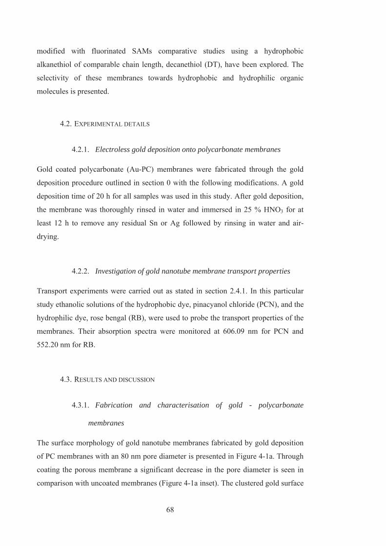
68
modified with fluorinated SAMs comparative studies using a hydrophobic
alkanethiol of comparable chain length, decanethiol (DT), have been explored. The
selectivity of these membranes towards hydrophobic and hydrophilic organic
molecules is presented.
4.2. EXPERIMENTAL DETAILS
4.2.1. Electroless gold deposition onto polycarbonate membranes
Gold coated polycarbonate (Au-PC) membranes were fabricated through the gold
deposition procedure outlined in section 0 with the following modifications. A gold
deposition time of 20 h for all samples was used in this study. After gold deposition,
the membrane was thoroughly rinsed in water and immersed in 25 % HNO3 for at
least 12 h to remove any residual Sn or Ag followed by rinsing in water and air-
drying.
4.2.2. Investigation of gold nanotube membrane transport properties
Transport experiments were carried out as stated in section 2.4.1. In this particular
study ethanolic solutions of the hydrophobic dye, pinacyanol chloride (PCN), and the
hydrophilic dye, rose bengal (RB), were used to probe the transport properties of the
membranes. Their absorption spectra were monitored at 606.09 nm for PCN and
552.20 nm for RB.
4.3. RESULTS AND DISCUSSION
4.3.1. Fabrication and characterisation of gold - polycarbonate
membranes
The surface morphology of gold nanotube membranes fabricated by gold deposition
of PC membranes with an 80 nm pore diameter is presented in Figure 4-1a. Through
coating the porous membrane a significant decrease in the pore diameter is seen in
comparison with uncoated membranes (Figure 4-1a inset). The clustered gold surface

69
seen on the membranes is the typical morphology of gold films prepared by
electroless deposition. In this work, gold deposition parameters were carefully
chosen to provide preparation of optimum films. A pH of 8 was chosen for the gold
deposition bath as it decreases the rate of the deposition reaction as a result of the
reduction of gold by formaldehyde. This approach has been shown to allow a more
homogeneous layer of gold to form and provides preferential deposition within the
pores [4].
To confirm that gold deposition occurred inside the pores as well as on the top of
membrane surface TEM image of a microtomed section of a gold plated membrane is
shown in Figure 4-1b. The gold particles (black dots) line the entire length of the
pore, confirming gold deposition is taking place within the depths of the pore and the
gold on the face does not obstruct the pore openings. Furthermore SEM of liberated
gold nanotubes after chemical etching or dissolution of the PC membrane confirmed
the presence of gold down the length of the pore (Figure 4-1 c & d).
Figure 4-1. a) SEM image showing the surface morphologies of gold nanotube membranes prepared
using a polycarbonate membrane as the template with a nominal pore diameter of 80nm. Inset:
uncoated polycarbonate membrane. b) TEM cross section of 30nm PC membrane plated with gold for
20h. c) Fully dissolved PC membrane resulting in a standing array of gold nanotubes supported by the

70
surface gold layer (PC pore diameter: 800 nm). d) Surface etched Au-PC membrane revealing the tips
of the gold nanotubes (PC pore diameter: 200 nm).
4.3.2. Electrochemical characterisation of thiol modified gold -
polycarbonate membranes
PFDT and DT functionalised Au-PC membranes were probed for passivating
properties of their self-assembled monolayers by ferricyanide as a redox probe.
Figure 4-2a shows comparative cyclic voltammetry (CV) measurements of bare and
modified Au-PC membranes. The shape of the CV peak is used to assess the quality
of the monolayer as it provides information regarding the electron-transfer of the
redox probe through the monolayer [20]. The peak-shaped CV of DT-Au-PC
membranes indicate diffusion-limited electron transfer characteristic of closely
spaced defect sites or large bare areas of uncoated gold. PFDT-Au-PC membranes
give a peak-less CV with lower current densities which indicates a denser monolayer
with lower defects in comparison with DT. To estimate the fraction of these defects,
CV results of gold oxide stripping experiments are shown in Figure 4-2b. A
significantly larger reduction peak for DT in comparison with PFDT confirms that
the DT monolayer is more defective. These observations are not surprising as it is
known that fluorocarbon chains assume a helical conformation making them more
rigid than analogous hydrocarbon chains [21]. The perfluorocarbon helices are
intramolecularly stabilised and will maintain their helical conformation whereas
hydrocarbon chains do not have this degree of intermolecular stability [14, 23].
These factors all contribute to the enhanced stability of fluorocarbon SAMs against
mechanical friction, thermal stress and extreme acid/base conditions [8].
The electrochemical results presented provide information on the SAMs properties of
the top surface of the membranes rather than inside the pores. These results do not
provide an indication of the quality inside the pores. The structure of thiols within
confined spaces such as pores is poorly understood and very difficult to probe [22].
Given the highly curved surface it is very likely that the SAM is not as well ordered
or well-packed as on a planar surface which was found to be the case in several other
studies [7, 22]. However, as on the planar surface, it would be reasonable to expect

71
the perfluorinated chains to form higher quality layers in the pores than alkane
chains.
Figure 4-2. Typical CVs obtained for unmodified, and thiol-modified gold nanotube membranes,
PFDT-Au-PC and DT-Au-PC in (a) an electron-transfer experiment performed using a redox probe 1
mM ferricyanide in 0.2 M KCl (scan rate 100 mVs 1) and (b) a gold reduction experiment performed
in 0.1 M sulphuric acid (scan rate 100 mVs 1).

72
4.3.3. Transport and selectivity of gold - polycarbonate membranes
The transport and selectivity properties of PFDT and DT modified gold nanotube
membranes were explored using two molecular dyes: pinacyanol chloride (PCN) that
has dominant hydrophobic properties and rose bengal (RB) with more hydrophilic
properties. A summary of the permeation data of these dyes through functionalised
and unfunctionalised membranes are shown in Table 4-1. The flux of the dyes
through each of the membranes was documented and the ratio of the flux for PCN
and the flux for RB (selectivity ratio) was determined. For an unfunctionalised
membrane we find that the flux of RB is 7.3 times smaller than PCN. The observed
difference in transport is due to the fact that PCN is smaller than RB and so can pass
through the membrane more easily.
Table 4-1. Transport and selectivity properties of functionalised and bare gold nanotube membranes
(errors obtained from three replicate measurements).
Flux of permeate molecule
(mol cm-2 h-1)Selectivity
PCN RB PCN:RB
Au-PC4.02 x 10-8
± 2.64 x 10⁻⁹
5.53 x 10⁻⁹
± 1.45 x 10⁻⁹ 7.27
DT-Au-PC4.23x10-8
± 3.71x10⁻⁹
4.94 x 10⁻⁹
± 5.37 x 10⁻¹⁰ 8.56
PFDT-Au-PC 3.76 x 10⁻⁸
± 1.47 x 10⁻⁹
2.31 x 10⁻⁹
± 2.03 x 10⁻¹⁰ 16.28
Figure 4-3 represents the transport of both probe dyes through the membranes
functionalised with the alkane thiol, DT and the fluorinated thiol, PFDT. The data
confirms that both functionalised membranes favour transport of the hydrophobic
dye over the hydrophilic dye. Thus through functionalising the membrane with a
hydrophobic thiol it has become chemically sensitive, favouring the transport of
hydrophobic species. However, the PFDT-Au-PC membrane shows improved
transport of hydrophobic molecules over hydrophilic molecules compared to the DT-
Au-PC membrane. From Table 4-1 it can be seen that the selectivity ratio through the
PFDT-Au-PC membrane is 16.27 whereas the DT-Au-PC membrane has a selectivity

73
ratio of only 8.56. The selectivity ratio of the PFDT-Au-PC membrane has increased
by 124% in comparison to the unfunctionalised membrane while the DT-Au-PC
membrane has only increased a small amount (18 %). From Table 4-1, the flux of
PCN through unfunctionalised and functionalised membranes are very similar,
indicating that the transport of the hydrophobic dye is not largely affected by the
introduction of a hydrophobic SAM to the membrane. The addition of thiols would
be expected to decrease the membrane pore size and consequently decrease the
transport. However, it is important to consider the partition effect during the
diffusion of molecules through the thiol modified pores of the membrane. The
partitioning of organic solutes through various membranes and molecular structures
such as SAMs and lipid bilayers and their impact on transport properties have been
explored and reported in literature [23-26]. In our case it is likely that PCN can
partition into the thiol layers as well as the solvent at the centre of the pore. This is
further verified in terms of Fick’s law of diffusion;
J= P(C1-C2) Eq. (2)
Where J is the flux across the membrane, P is the permeability constant, C1 is the
concentration in the feed cell and C2 is the concentration in the permeate cell [27].
The permeability constant of the membrane is proportional to the diffusion
coefficient and the partition coefficient of the dye into the membrane. For the case of
an unfunctionalised and functionalised membrane, the area and concentration
difference are the same and PCN provides similar transport rates (Table 4-1) which
means the permeability constants must be comparable (Eq. 2). This is perhaps a
surprising result as the narrowing of the pores by the adsorbed monolayer would be
expected to hinder the diffusion. As mentioned in section 4.3.3 given the highly
curved surface within the pores it is very likely that the SAM is not well ordered or
well-packed [7, 22]. Therefore the thickness of the thiol layer within the pores will
be small and there will be only slight narrowing of the pores due to the adsorbed
monolayer. However, in the case where the molecules being transported can dissolve
into the monolayer [7, 22], diffusion across the membrane can occur through the
thiol layer and through the centre of the pore. The partition of the dye from the pore
into the thiol layer will alter the concentration gradient between the feed cell and the
solvent inside the pore. An overall increase in the concentration gradient in the pore
would be expected which would increase the flow across the membrane
compensating for the narrower pore size.

74
It is also important to consider the adsorption and retention of the dye onto the
functional layer or gold surface. PFDT is highly antifouling and therefore the dye is
highly unlikely to adsorb and be retained by the functional layer. Consequently the
PFDT layer will permit the passage of hydrophobic molecules and the reduction of
the flux of the hydrophilic dye is due to the hydrophobic-hydrophilic effects as
described. However, DT is not antifouling and therefore the dye may adsorb onto the
layer and become retained, thus decreasing the effective pore diameter of the
membrane and lowering the transport rate of the dye. Adsorption of the dye onto the
DT layer would also result in an increase in the concentration of the dye immediately
within the membrane and hence generate less driving force for the dye to transport
from the feed cell into the membrane. However the PCN transport rate is found to
increase slightly after DT modification and therefore adsorption doesn’t appear to be
influencing the flux. The hydrophilic dye flux is found to decrease after DT
modification which may be attributed to adsorption of the dye onto the DT layer. If
adsorption is used to explain the transport properties of the DT membrane then RB
can adsorb to the DT layer while PCN does not adsorb. To determine whether the
transport effects are due to hydrophilic-hydrophobic interactions or adsorption
effects, it would be desirable to perform the experiments using a range of dyes.

75
Figure 4-3 Transport of a hydrophobic (PCN) and hydrophilic (RB) dye through a gold nanotube
membrane functionalised with the hydrophobic thiols a) decanethiol and b) perfluorodecanethiol.
Figure 4-4 directly compares the hindrance of the PFDT and DT modified
membranes towards the transport of the hydrophilic dye, RB. The introduction of
either hydrophobic thiol decreases the rate of transport of the hydrophilic species
through the pore in comparison with unmodified membranes. This is expected as the
membranes exhibit a hydrophobic environment that the hydrophilic dye would have
difficulty partitioning into. However, this result clearly shows that the PFDT

76
derivatised membrane is more effective at rejecting the hydrophilic dye than the DT
membrane. Unlike the case for the hydrophobic dye, PCN, it is unlikely that the
hydrophilic dye, RB, will partition into the organic monolayer and hence the
reduction of the transport rate is attributed to the reduction in the pore diameter from
the adsorbed monolayer and the rejection of hydrophilic species from the
hydrophobic surface. Electrochemical characterisation of PFDT on the membrane
surface showed a more ordered, dense, and less defective monolayer film in
comparison with DT. Even though the thiols are not well ordered or well packed
within pores [7, 22] it is expected that the PFDT layer within a pore will form a
higher quality layer than a DT layer and hence yield a smaller pore. DT monolayers
form a thinner layer than PFDT as a consequence of weaker intermolecular forces
and a more disordered configuration, leading often to collapsed DT molecules [14].
This explains the lower transport rate observed as the effective pore diameter of a
PFDT-membrane would be smaller than a DT-membrane.
Figure 4-4 Transport of the hydrophilic dye (RB) through an unfunctionalised membrane and
membranes functionalised with decanethiol and perfluorodecanethiol.
4.4. CONCLUSIONS
Gold nanotube membranes were successfully synthesised using the electroless
deposition technique, forming gold nanotubes within the pores of a porous
polycarbonate membrane. The functionalisation of gold nanotube membranes with
77
SAMs of fluorinated thiols (PFDT) was demonstrated showing that the transport and
selectivity properties of gold nanotube membranes can be varied by functionalisation
using thiol chemistry. PFDT functionalised membranes showed excellent sensitivity
for the transport of hydrophobic molecules over hydrophilic molecules. Their
transport, selectivity and stability properties were superior in comparison to
membranes functionalised with alkanethiol monolayers such as decanethiol.

78
4.5. REFERENCES
1. Demoustier-Champagne, S., and Delvaux, M., Preparation of polymeric and
metallic nanostructures using a template-based deposition method. Materials
Science and Engineering C, 2001. 15: p. 269–271.
2. Nishizawa, M., Menon, V.P., and Martin, C.R., Metal Nanotubule
Membranes with Electrochemically Switchable Ion-Transport Selectivity.
Science, 1995. 268: p. 700-702.
3. Menon, V.P., and Martin, C.R., Fabrication and Evaluation of Nanoelectrode
Ensembles. Analytical Chemistry, 1995. 67: p. 1920- 1928.
4. Gilliam, R.J., Thorpe, S.J., and Kirk, D.W., A nucleation and growth study of
gold nanowires and nanotubes in polymeric membranes. Journal of Applied
Electrochemistry, 2007. 37(2): p. 233-239.
5. De Leo, M., Kuhn, A., and Ugo, P., 3D-ensembles of gold nanowires:
Preparation, characterization and electroanalytical peculiarities.
Electroanalysis, 2007. 19(2-3): p. 227-236.
6. De Leo, M., Pereira, F.C., Moretto, L.M., Scopece, P., Polizzi, S., and Ugo,
P., Towards a better understanding of gold electroless deposition in track-
etched templates. Chemistry of Materials, 2007. 19(24): p. 5955-5964.
7. Hulteen, J.C., Jirage, K.B., and Martin, C.R., Introducing Chemical
Transport Selectivity into Gold Nanotubule Membranes. Journal of the
American Chemical Society, 1998. 120: p. 6603-6604.
8. Fukushima, H., Seki, S., Nishikawa, T., Takiguchi, H., Tamada, K., Abe, K.,
Colorado, R., Graupe, M., Shmakova, O.E., and Lee, T.R., Microstructure,
wettability, and thermal stability of semifluorinated self-assembled
monolayers (SAMs) on gold. Journal of Physical Chemistry B, 2000. 104(31):
p. 7417-7423.
9. Schlenoff, J.B., Li, M., and Ly, H., Stability and self-exchange in alkanethiol
monolayers. Journal of the American Chemical Society, 1995. 117(50): p.
12528-12536.
10. Zamborini, F.P. and Crooks, R.M., Corrosion passivation of gold by n-
alkanethiol self-assembled monolayers: Effect of chain length and end group.
Langmuir, 1998. 14(12): p. 3279-3286.

79
11. Schoenfisch, M.H. and Pemberton, J.E., Air stability of alkanethiol self-
assembled monolayers on silver and gold surfaces. Journal of the American
Chemical Society, 1998. 120(18): p. 4502-4513.
12. Delamarche, E., Michel, B., Kang, H., and Gerber, C., Thermal-stability of
self-assembled monolayers. Langmuir, 1994. 10(11): p. 4103-4108.
13. Horn, A.B., Russell, D.A., Shorthouse, L.J., and Simpson, T.R.E., Ageing of
alkanethiol self-assembled monolayers. Journal of the Chemical Society-
Faraday Transactions, 1996. 92(23): p. 4759-4762.
14. Tamada, K., Ishida, T., Knoll, W., Fukushima, H., Colorado, R., Graupe, M.,
Shmakova, O.E., and Lee, T.R., Molecular packing of semifluorinated
alkanethiol self-assembled monolayers on gold: Influence of alkyl spacer
length. Langmuir, 2001. 17(6): p. 1913-1921.
15. Miura, Y.F., Takenaga, M., Koini, T., Graupe, M., Garg, N., Graham, R.L.,
and Lee, T.R., Wettabilities of self-assembled monolayers generated from
CF3-terminated alkanethiols on gold. Langmuir, 1998. 14(20): p. 5821-5825.
16. Alves, C.A. and Porter, M.D., Atomic force microscopic characterization of a
fluorinated alkanethiolate monolayer at gold and correlations to
electrochemical and infrared reflection spectroscopic structural descriptions
Langmuir, 1993. 9(12): p. 3507-3512.
17. Chidsey, C.E.D. and Loiacono, D.N., Chemical functionality in self-
assembled monolayers: structural and electrochemical properties. Langmuir,
1990. 6(3): p. 682-691.
18. Cosmacini, E. and Veronesi, V., A study of the tribological behaviour of
perfluoro-polyethers. Wear, 1986. 108.
19. Grampel, R.D.v.d., Surfaces of Fluorinated Polymer Systems. 2002:
Technische Universiteit Eindhoven.
20. Finklea, H.O., Self-assembled monolayers on electrodes, in Encyclopedia of
Analytical Chemistry, R.A. Meyers, Editor. 2006, John Wiley & Sons Ltd:
Chichester.
21. Liu, G.Y., Fenter, P., Chidsey, C.E.D., Ogletree, D.F., Eisenberger, P., and
Salmeron, M., An unexpected packing of fluorinated n-alkane thiols on
Au(llI): A combined atomic force microscopy and x-ray diffraction study.
Journal of Chemical Physics, 1994. 101(5): p. 4301-4306.

80
22. Jirage, K.B., Hulteen, J.C., and Martin, C.R., Effect of thiol chemisorption on
the transport properties of gold nanotubule membranes. Analytical
Chemistry, 1999. 71(21): p. 4913-4918.
23. Bemporad, D., Essex, J.W., and Luttmann, C., Permeation of small molecules
through a lipid bilayer: A computer simulation study. Journal of Physical
Chemistry B, 2004. 108(15): p. 4875-4884.
24. Paula, S., Volkov, A.G., VanHoek, A.N., Haines, T.H., and Deamer, D.W.,
Permeation of protons, potassium ions, and small polar molecules through
phospholipid bilayers as a function of membrane thickness. Biophysical
Journal, 1996. 70(1): p. 339-348.
25. Janshoff, A. and Steinem, C., Transport across artificial membranes - an
analytical perspective. Analytical and Bioanalytical Chemistry, 2006. 385(3):
p. 433-451.
26. Ulbricht, M., Advanced functional polymer membranes. Polymer, 2006. 47:
p. 2217–2262.
27. Lodish, H., Darnell, J., Matsudaira, P., Baltimore, D., and Berk, B.,
Molecular cell biology. 1995: W. H. Freeman Company.

CHAPTER 5 THE EFFECTS OF SURFACE FUNCTIONALITY
POSITIONING ON THE TRANSPORT PROPERTIES OF
MEMBRANES Several hybrid membrane structures based on polycarbonate membranes were
created in which gold was deposited on different areas on the membrane; on one of
the membrane interfaces, within the pores of the membrane and completely coating
all surfaces of the membrane. Gold-thiol chemistry was exploited in which the thiols
only assembled on the gold coated regions of the membrane thus providing
controlled positioning of functional regions. The effects of the controlled positioning
of functional groups on the transport properties of the membrane were investigated.
5. Chapter 5

82
5.1. INTRODUCTION
Surface modification can result in highly selective separations due to the chemical
interaction between the permeate and the molecules on the surface [1-2] and can also
be used to produce anti-fouling surfaces [3]. However, the application of surface
modification in commercial membranes is not widely considered other than their use
as anti-fouling coatings [4-6]. Research into exploiting surface chemistry to enhance
transport selectivity and sensing is relatively new but is exceedingly important
especially in the biotechnology industry, which requires separation of complex, and
often quite similar, biomolecules and controlled delivery of drugs. Consequently,
surface modification is an important factor in membrane design as it has the potential
to increase the flux, selectivity and stability of the membrane.
Polycarbonate membranes were used in this study due to their uniform cylindrical
pores and narrow pore size distribution [4]. These membranes can be considered
model systems for investigating membrane transport phenomena. Therefore in
regards to the pore structure, polycarbonate membranes bear a much closer
resemblance to an ideal membrane structure. However, polycarbonate membranes do
not offer a suitable surface to proceed with further surface chemistry modifications.
Therefore, electroless deposition was used to coat the polycarbonate membranes with
gold, this procedure provides the ability to tailor surface properties by chemical and
biochemical functionalisation [8-14]. A range of molecules can be attached to gold
via a thiol linkage [5-6], thereby altering the membrane surfaces with functional
groups. The immobilisation of appropriate functional groups on the membrane
surface allows for selective transport of permeate molecules [1].
The groundwork for this study is based on the experiments described in chapter 4.
This chapter presents the investigation of the effect on the transport properties of
membranes functionalised with SAMs. In particular, the effect of the positioning of
functional groups on the membrane has previously not been investigated. Such
studies are important to give insight into how surface modifications may impact the
transport properties of porous membranes in order to develop more efficient
separation processes. Therefore in our work we have devised a set of membranes in

83
which only specific regions of the membrane are functionalised. We have used the
electroless gold deposition method and gold sputter coating to provide control over
which areas of the membrane are coated in gold and hence the areas of the membrane
that can be subsequently functionalised with SAMs of thiols. In this work we
produced several differently structured gold nanotube membranes based on
polycarbonate membranes. This was achieved by coating different areas of the
polycarbonate membrane with gold, one with gold coating the membrane entirely
(external surfaces and within the pores); Au(ext+pore)PC membrane, one with gold
coated only within the pores; Au(pore)PC membrane and a membrane coated in gold
only one interface; Au(ext)PC membrane (Figure 5-1). Here interface refers to the face
of the membrane that will be facing the feed solution during transport studies. The
membranes were later functionalised with thiols in which the thiols only assembled
on the areas of the membrane where gold has been deposited (Figure 5-1).
Figure 5-1 Schematics of the hybrid gold-polycarbonate structures investigated in this study; (a)
unmodified PC, (b) Au(ext+pore)PC, (c) Au(pore)PC and (d) Au(ext)PC and corresponding cross sectional
images of the membranes after functionalisation, displaying the areas PFDT is adsorbed on.
5.2. EXPERIMENTAL DETAILS
5.2.1. Electroless gold deposition
Electroless deposition was used to fabricate the Au(ext+pore)PC and Au(pore)PC
membranes. The gold deposition procedure outlined in section 0 was carried out with

84
the following modifications. A gold deposition time of 20 h was used in this study
which significantly reduces the pore size of the membrane without closing the pores.
This gold deposition procedure produces the Au(ext+pore)PC membrane in which the
gold is deposited on all surfaces including those at the interface and within the pores
of the membrane. In order to produce the Au(pore)PC membrane one more step is
carried out which involves removing the layers of gold on the membrane by wiping
the surfaces with a cotton tip whilst the membrane is still wet.
5.2.2. Gold sputtering onto polycarbonate membranes
In order to fabricate the Au(ext)PC membrane, polycarbonate membranes were
sputtered with 12 nm of gold on the top interface of the membrane. A high vacuum
turbo evaporation system, EMITECH K975X (Quorum technologies, UK), was used
for the sputter coating of membranes with thin gold films. The thickness of deposited
films was precisely controlled by the thickness monitor located inside the chamber.
5.2.3. Investigation of membrane transport properties
Transport experiments were carried out as stated in section 2.4.1. In this particular
study ethanolic solutions of the hydrophobic dye, pinacyanol chloride (PCN), and the
hydrophilic dye, rose bengal (RB), were used to probe the transport properties of the
membranes. Their absorption spectra were monitored at 606.09 nm for PCN and
552.20 nm for RB.
5.3. RESULTS AND DISCUSSION
5.3.1. Fabrication and characterisation of gold - polycarbonate
membranes
SEM was used to examine the surface morphology of the Au(ext+pore)PC, Au(pore)PC
and Au(ext)PC membranes. Images of the various membranes are shown in Figure
5-2. The rough gold surface seen on the Au(ext+pore)PC membrane is the typical
morphology of gold films prepared by electroless deposition (Figure 5-2a). The

85
electroless deposition of gold provided a significant reduction in the pore diameter of
the Au(ext+pore)PC and Au(pore)PC membranes (Figure 5-2 (a-b)) in comparison with
the uncoated PC membranes (Figure 5-2c inset). For the Au(ext+pore)PC and Au(pore)PC
membranes the pore size has been reduced to molecular dimensions and the pores are
below the resolution of the SEM. Therefore samples were prepared using the same
gold deposition procedure but with PC membranes with larger pore sizes (80 nm) in
order to illustrate the reduction in the pore size achievable with electroless deposition
(Figure 5-3). The pore diameter of the 80 nm PC membranes have been reduced to
29.4 ± 6.5 nm and 43.8 ± 13.3 nm for a Au(ext+pore)PC and Au(pore)PC membrane
respectively. SEM images for the Au(pore)PC membranes confirm that the gold layers
on the interfaces of the membrane were removed successfully. The only gold present
on the interface of the membrane is attributed to the tips of the gold nanotubes which
have formed within the pores of the membrane (light rings, Figure 5-3b). The
Au(ext)PC membrane was formed through sputter coating one of the interfaces of the
polycarbonate membrane with 12 nm of gold. From SEM images (Figure 5-2c) there
has been a decrease in the pore size from 30 nm to 15 nm. The surface of the sputter
coated membrane appears smoother and more homogeneous than the electroless
deposition coated membranes.
Cross sections of the membranes were viewed under a TEM in order to confirm gold
deposition within the pores of the Au(ext+pore)PC and Au(pore)PC membranes and the
absence of gold within the pores of the Au(ext)PC membrane (Figure 5-4). In the
cross section for the Au(ext+pore)PC membrane the gold is deposited on the top and
bottom surfaces of the membrane and also within the pores (Figure 5-4a). For the
Au(pore)PC membrane gold is seen to be distributed only within the pores (Figure
5-4b). Due to the slightly tortuous nature of the pores in commercial polycarbonate
membranes, it is not possible to form a cross section exactly along the grain of the
pores which is why it appears in these images that the gold does not extend the entire
length. However, gold is seen to be deposited in the centre of the membrane which
indicates that gold deposition has extended through the entire thickness of the
membrane. The TEM image for the Au(ext)PC membrane (Figure 5-4c) confirms gold
deposition has occurred on the top surface of the membrane and there is no evidence
of gold within the pores.

86
Figure 5-2 SEM images of the surface of the a) Au(ext+pore)PC, b) Au(pore)PC and c) Au(ext)PC
membranes used in this study. Inset: 30 nm unmodified PC membrane.

87
Figure 5-3 SEM images of (a) Au(ext+pore)PC membrane and (b) Au(pore)PC membrane based on 80 nm
pore size polycarbonate membranes. Inset: uncoated polycarbonate membrane.

88
Figure 5-4 TEM images of the cross section of (a) Au(ext+pore)PC, (b) Au(pore)PC and (c) Au(ext)PC
membranes. The dark regions are region of high gold concentrations. Insets: schematics of their
corresponding membrane cross-section.
5.3.2. Surface functionalisation of gold - polycarbonate membranes
For the three Au-PC membranes fabricated, chemical specificity either on the
entirety of the membrane, only within the pores of the membrane or only on one of
the interface of the membrane can be produced. Chemical selectivity is imparted to
the gold nanotube membranes by incorporating the highly hydrophobic and durable
thiol, perfluorodecanethiol (PFDT). The SAM is formed wherever the gold is
deposited therefore controlling the areas of the membrane that are functionalised
with the hydrophobic thiol. Water droplet contact angle measurements were
performed in order to verify attachment of the thiol to the gold surface and to
determine the effects of hydrophobic surface functionalisation. Further evidence of
PFDT attachment to gold membranes was ascertained in chapter 4 using cyclic
voltammetry to determine the blocking of the gold surface by the thiols and the
ability to remove the thiols.
Table 5-1 displays the water contact angle measurements on the surfaces of
unfunctionalised and PFDT-functionalised membranes. For the Au(ext+pore)PC
membrane an increase in contact angle from 53o to 94o is observed after
functionalisation which is expected as the face of the membrane is coated with gold

89
and hence subsequently covered with PFDT. For this same reason, a fairly large
contact angle increase (from 76o to 103o) is also observed for the Au(ext)PC
membrane (Table 5-1). Both Au(ext+pore)PC and Au(ext)PC membranes have gold
completely covering the face of the membrane and therefore the hydrophobic thiol
will self assemble onto the face of these membranes. However, a larger increase in
contact angle is observed for the electrolessly coated surface which is most likely
attributed to the roughness of the electroless gold layer. Superhydrophobic surfaces
are attained when the surfaces are made exceedingly rough [7]. Electroless
deposition occurs as the nucleation and growth of gold nanoparticles [8] thus
generating a slightly rougher surface than the sputter coating method.
In the case of the Au(pore)PC membrane the contact angle remained relatively constant
after PFDT modification (see Table 5-1). This is due to the removal of the layer of
gold on the top surface of the membrane and so the thiol will attach only to the gold
within the pores. This result confirms that the technique used for the removal of the
gold layers on the faces of the membrane is effective.
While these contact angle results confirm the attachment of thiols onto the gold, they
only describe the environment at the face of the membrane and not the chemical
environment within the pores and hence do not represent the hydrophobic properties
of the full membrane material. Therefore transport experiments with probe dyes are a
much more suitable method to ascertain the full extent that thiol modification has on
the properties of the membrane.
The contact angle experiments give insight into the solvent structuring of water in the
vicinity of fluorocarbon layers. Whilst fluorocarbon layers are expected to have a
greater affinity to water than their hydrocarbon counterparts, layers consisting of
fluorocarbons are found to be hydrophobic. The enhanced hydrophobicity of
fluorinated SAMs is due to the bulkiness of the thiols and hence larger thiol
interspacing resulting in poorer van der Waals interactions with water [9]. The
interactions of water with fluorinated layers are found to be primarily van der waals
interactions and not dependent on electrostatic interactions [9]. The decreased van

90
der waals interactions with water are expected to influence the transport rates of the
dyes through the functionalised membranes.
Table 5-1 Advancing contact angle measurements for the unfunctionalised and PFDT functionalised
Au-PC membranes.
Membrane
structure
Contact angle (o) for
unfunctionalised
membrane
Contact angle (o) for
PFDT-functionalised
membrane
Au(ext+pore)PC 52.9 6.2 93.5 1.8
Au(pore)PC 68.2 6.3 70.5 4.7
Au(ext)PC 76.3 2.9 102.7 1.4
5.3.3. Transport properties of gold – polycarbonate membranes
To explore the transport and selectivity properties of hydrophobic (PFDT) modified
hybrid Au-PC membranes, the flux of the dyes: PCN (hydrophobic) and RB
(hydrophilic) were measured. The transport experiments carried out provide detailed
information on the interactions between the dyes and the surface functional
molecules allowing determination of the impact that the positioning of functional
molecules has on the transport properties of the membrane. Figure 5-5 presents the
transport of the probe dyes through the Au(ext+pore)PC, Au(pore)PC and Au(ext)PC
membranes before and after surface modification with PFDT. Straight-line plots are
obtained indicating steady state (Fick’s first law [10]) diffusion across the
membrane. A summary of the permeation data of these dyes through functionalised
and unfunctionalised Au-PC membranes is presented in Table 5-2. In this study it is
important to note the transport results for the Au(ext+pore)PC and Au(pore)PC
membranes can be directly compared, however the Au(ext)PC membrane transport
data cannot be directly compared to the Au(ext+pore)PC and Au(pore)PC membranes as
the pore size is considerably larger for the Au(ext)PC membrane (10-15 nm pore size).
The transport rates of the dyes though the Au(ext)PC membrane is almost a magnitude
larger than that observed for the Au(ext+pore)PC and Au(pore)PC membranes (Table 5-2)
due to the considerably larger pore size.

91
Table 5-2 Transport and selectivity properties of functionalised and bare gold membranes (errors
obtained from three replicate measurements).
Flux (mol cm-2 h-1)
Membrane Treatment PCN RB Flux Ratio
(PCN:RB)
Increase in
flux ratio
Au(ext+pore)PC
Bare 4.02 x 10⁻⁸
± 2.64 x 10⁻⁹
5.12 x 10⁻⁹
± 5.81 x 10⁻¹⁰ 7.85
107%
PFDT 3.76 x 10⁻⁸
± 1.47 x 10⁻⁹
2.31 x 10⁻⁹
± 2.03 x 10⁻¹⁰ 16.28
Au(pore)PC
Bare 4.17 x 10⁻⁸
± 2.24 x 10⁻⁹
5.43 x 10⁻⁹
± 5.47 x 10⁻¹⁰ 7.68
24%
PFDT 3.95 x 10⁻⁸
± 2.24 x 10⁻⁹
4.12 x 10⁻⁹
± 1.68 x 10⁻¹⁰ 9.59
Au(ext)PC
Bare 2.82 x 10⁻⁷
± 3.36 x 10⁻⁸
1.06 x 10⁻⁷
± 1.53 x 10⁻⁸ 2.65
15%
PFDT 2.52 x 10⁻⁷
± 1.42 x 10⁻⁸
8.08 x 10⁻⁸
± 3.68 x 10⁻⁹ 3.12
For each of the unfunctionalised Au-PC membranes, there is already a separation of
the two dyes (Table 5-2, Figure 5-5). The observed difference in transport is due to
the variation in the diffusion coefficients of the dyes which are attributed to factors
such as the size, charge, shape and solubility of the molecules in the solvent. The
unfunctionalised membrane transport data is primarily used as a basis to compare the
functionalised membrane results to and hence ascertain the precise impact of
functionalisation of the transport properties of the membrane. As the Au(ext+pore)PC
and Au(pore)PC membranes have comparable structure dimensions, similar degrees of
dye separation for these membranes are observed (the flux ratio of PCN:RB is 7.27
and 7.68 respectively). The dye transport rates through the unfunctionalised
Au(ext+pore)PC and Au(pore)PC membranes are similar as the structures of these
membranes and are identical with the exception of the absence of gold layers on the

92
interface of the Au(pore)PC membrane. These membranes have the same pore size and
their thicknesses are comparable regardless of the presence or absence of gold layers
on the faces of the membrane. The thickness of the electroless gold layer on the
interface of the Au(ext+pore)PC membrane (Figure 5-4a) is negligible compared to the
overall thickness of the membrane (~6 m). The unfunctionalised Au(ext)PC
membrane exhibits a smaller flux ratio of 2.65 as the pore size is significantly larger
than the size of the probe dyes, thus offering less resistance to their transport. As
properties such as shape and size have an impact on the diffusion properties of the
dyes, any minute differences in these properties between the dyes will be less
distinguishable at larger pore sizes due to less confinement and surface – molecule
interactions.
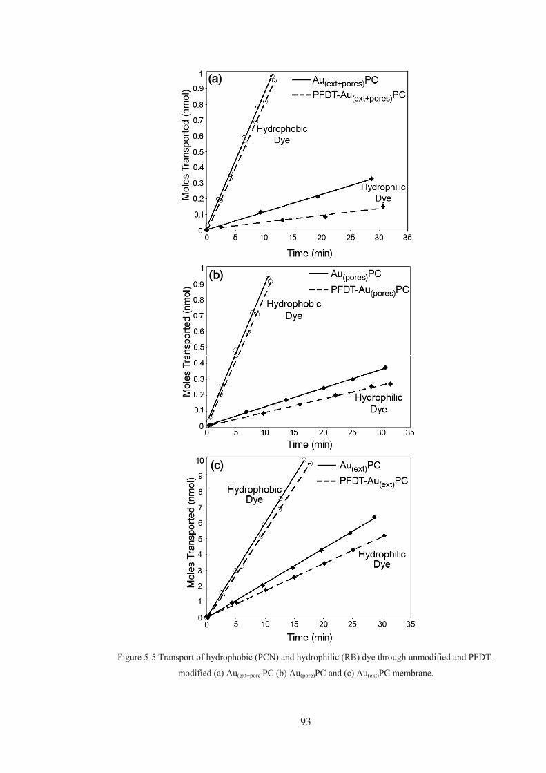
93
Figure 5-5 Transport of hydrophobic (PCN) and hydrophilic (RB) dye through unmodified and PFDT-
modified (a) Au(ext+pore)PC (b) Au(pore)PC and (c) Au(ext)PC membrane.

94
The overall effect of functionalising the Au-PC membranes with PFDT results in a
hindrance in the transport of the hydrophilic dye leading to an increase in the flux
ratio of the membrane (Table 5-2). Therefore through instilling a hydrophobic
surface functionality to the membrane we have created a membrane with
hydrophobic properties which can enhance the separation between hydrophilic and
hydrophobic molecules. It is important to consider the partitioning of organic solutes
into the SAM formed within the pores. The ability for molecules to partition into
molecular layers such as SAMs and lipid bilayers and the impact this has on
transport properties have been explored and reported in the recent literature [11-14].
In our case it is likely that PCN can partition into the thiol layers and thus diffusion
across the membrane can occur through both the thiol layer and the solvent in the
centre of the pore resulting in similar PCN transport rates through PFDT modified
and unmodified membranes. The PFDT modified membranes exhibits a hydrophobic
environment in which the hydrophilic dye would not enter into easily. Furthermore,
it is unlikely that the RB will partition into the hydrophobic organic monolayer and
hence the reduction of the transport rate can also be attributed to a reduction in the
pore diameter from the adsorbed monolayer. These contributing factors lead to an
overall decrease in the transport of RB through the PFDT modified membranes. Thus
the PFDT modified membranes facilitate the transport of hydrophobic species
through the membrane while hindering the transport of hydrophilic species. While
the Au(ext)PC membrane displays the smallest increase in flux ratio (15 %), this
membrane facilitates transport of the dyes a magnitude faster than the Au(ext+pore)PC
and Au(pore)PC membranes due to the considerably larger pore size. While the
Au(ext+pore)PC and Au(pore)PC membranes present larger increases in the flux ratios
after functionalisation (107 % and 24 % respectively), these membranes exhibit
smaller rates of transport due to the small pore diameters.
Au(ext+pore)PC membranes exhibit the greatest increase in selectivity of the
hydrophobic dye over the hydrophilic dye after surface modification with PFDT
(Table 5-2). After functionalisation the membrane exhibits an increase in flux ratio of
107 % which is due to the entire membrane being coated in the hydrophobic thiol
layer. This membrane presents an environment into which the hydrophilic dye will

95
not partition into easily. The major influence on the permeability and flux of a
particular molecule through the membrane will be due to the ability of the molecule
to partition into the membrane. The partition coefficient is expected to differ for the
different chemical environments introduced into the membranes by means of surface
functionalisation. The partition coefficient K or “solubility” of the molecules
between the membrane and the adjacent solution is defined by
0
0
F
M
CC
K (1)
where CM0 is the concentration immediately within the membrane and CF0 is the feed
solution concentration adjacent to the face of the membrane. Figure 5-6a describes
the concentration profile for RB as it approaches the PFDT-Au(ext+pore)PC membrane,
where CF is the feed cell concentration, CF0 is the concentration of the feed solution
immediately at the interface of the membrane, CM0 is the concentration immediately
inside the membrane and CP is the concentration of the permeate solution. The
gradient of the concentration profile within the membrane describes the rate of
transport across the membrane. The concentration profile of RB as it approaches the
face of the membrane will diminish due to the hydrophobic layer positioned on the
face of the membrane (CF0 < CF, Figure 5-6a). A lower concentration at the interface
of the membrane will result is a smaller concentration difference across the
membrane and hence less driving force for the molecule to pass through the
membrane. Furthermore, CM0 will be much smaller than CF0 due to the thiol layer
present within the pores, thus resulting in a small partition coefficient (Eq. 1). Each
of these factors contribute to a decreased concentration gradient across the
membrane. The hydrophobic dye transport has not changed much with the addition
of the hydrophobic thiol layer. Therefore, the inclusion of this SAM has not hindered
the transport of the hydrophobic dye through the membrane.

96
Figure 5-6 Concentration profiles for RB across PFDT modified a) Au(ext+pore)PC, b) Au(pore)PC and c)
Au(ext)PC membranes.
The Au(pore)PC membrane exhibits a slight increase in the flux ratio after the thiol is
incorporated within the pores. Furthermore, the increase in flux ratio signifies that
thiol deposition has occurred within the confines of the pore. Raman spectroscopy
was used to confirm the presence of SAMs within the confined geometries of the
pores as discussed in chapter 3. SAMs are shown to have disordered orientation and
poor packing within narrow pores [15] which can partially explain the small increase
in flux ratio of 24 %, considerably lower than the increase observed for the
Au(ext+pore)PC membrane (107 %). The small increase could be due to a disordered
SAM layer within the pores and a lower density of thiols. However, the difference
between the flux increase of the Au(ext+pore)PC and Au(pore)PC membranes is too large
to only be attributed to the disorder of the thiol layer within the pores. The smaller
increase in the flux ratio for the Au(pore)PC membrane is most likely due to the
absence of the thiol layer on the face of the membrane. Figure 5-6b represents the
concentration profile of RB in the PFDT-Au(pore)PC membrane. Due to the absence
of the hydrophobic layer on the surface of the PFDT-Au(pore)PC membrane, there will
only be minor rejection of the hydrophilic dye away from the surface. Therefore the
concentration immediately adjacent to the membrane face (CF0) will only be slightly
smaller than the concentration of the feed solution (CF). There will be a slight
decrease in the concentration of RB directly within the membrane (CM0) due to the
hydrophobic layer within the pores. The ability of RB to partition into the Au(pore)PC
membrane is low due to the thiols within the pores, however CF0 for Au(pore)PC is
larger than CF0 for Au(ext+pore)PC and so there is a larger concentration difference of
RB across the Au(pore)PC membrane and hence a larger RB flux is observed. Due to
the significant difference in RB transport rates between the Au(ext+pore)PC and

97
Au(pore)PC membranes it is evident that surface functionalisation plays a larger role
than internal pore functionalisation in governing the transport properties of the
membrane. As with the Au(ext+pore)PC membrane, the transport of the hydrophobic
dye has not been hindered due to the incorporation of the hydrophobic thiol.
The Au(ext)PC membrane shows a slight increase in selectivity when functionalised
with PFDT due to a decrease in the transport of the hydrophilic dye (Table 5-2).
Given that the pore size is larger than the Au(ext+pore)PC and Au(pore)PC membranes,
this increase in selectivity is therefore more profound. The increase in selectivity for
the PFDT-Au(ext)PC membrane is 15 % which is comparable to the Au(pore)PC
membrane while still obtaining fluxes a magnitude greater. The concentration profile
of the Au(ext)PC membrane (Figure 5-6c) is similar to the Au(ext+pore)PC membrane.
The concentration of the dye at the surface of the membrane will taper off due to the
presence of PFDT. Although there is a lower RB concentration at the face of the
Au(ext)PC membrane, much like the Au(ext+pore)PC membrane, the ability of the dye to
permeate into the membrane is high due to no hindrance from thiols within the pores.
With smaller pore sizes, the flux ratio of the PFDT-Au(ext)PC membrane would be
expected to improve greatly as more forced molecule-surface interactions will occur.
These results support the conclusion that interface interactions have a larger
contribution to the transport properties of the membrane than pore interactions.
5.4. CONCLUSION
The production of several hybrid gold-polycarbonate membrane structures has been
demonstrated where the regions of gold deposition was controlled using sputtering
and electroless deposition techniques. Modification of the surface properties of the
membranes was carried out using a hydrophobic thiol (PFDT) in which PFDT only
assembled on the gold coated regions of the membranes thus providing controlled
positioning of functional areas. Overall, modification with PFDT resulted in a
hindrance in the transport of the hydrophilic dye and an enhancement in the
separation between hydrophilic and hydrophobic molecules. However, the
Au(ext+pore)PC membrane was found to exhibit the greatest increase in selectivity of
the hydrophobic dye over the hydrophilic dye after PFDT modification (107 %),

98
while the Au(pore)PC membrane exhibited a significantly lower flux ratio (24 %). The
increase in flux ratio of the Au(ext)PC membrane after PFDT modification (15 %) is
comparable to the Au(pore)PC membrane. However, given that the Au(ext)PC pore size
is larger than the Au(pore)PC membrane and facilitates dye flux a magnitude higher,
this increase in selectivity is more noteworthy. Therefore, it is apparent that
membrane interface functionalisation contributes more to the transport properties of
the membrane than pore functionalisation. The ability to repel molecules away from
the interface appears to be the governing factor in the membrane’s ability to control
the transport properties.

99
5.5. REFERENCES
1. Hulteen, J.C., Jirage, K.B., and Martin, C.R., Introducing Chemical
Transport Selectivity into Gold Nanotubule Membranes. Journal of the
American Chemical Society, 1998. 120: p. 6603-6604.
2. Majumder, M., Chopra, N., and Hinds, B.J., Effect of tip functionalization on
transport through vertically oriented carbon nanotube membranes. Journal of
the American Chemical Society, 2005. 127(25): p. 9062-9070.
3. Ulbricht, M., Matuschewski, H., Oechel, A., and Hicke, H.G., Photo-induced
graft polymerization surface modifications for the preparation of hydrophilic
and low-protein-adsorbing ultrafiltration membranes. Journal of Membrane
Science, 1996. 115(1): p. 31-47.
4. Fleisher, R.L., Price, P.B., and Walker, R.M., Nuclear tracks in solids:
Principles and applications. 1975, Berkeley, California: University of
California Press. 626.
5. Schreiber, F., Structure and growth of self-assembling monolayers. Progress
in Surface Science, 2000. 65(5-8): p. 151-256.
6. Love, J.C., Estroff, L.A., Kriebel, J.K., Nuzzo, R.G., and Whitesides, G.M.,
Self-assembled monolayers of thiolates on metals as a form of
nanotechnology. Chemical Reviews, 2005. 105(4): p. 1103-1169.
7. Zhang, X., Shi, F., Niu, J., Jiang, Y.G., and Wang, Z.Q., Superhydrophobic
surfaces: from structural control to functional application. Journal of
Materials Chemistry, 2008. 18(6): p. 621-633.
8. Gilliam, R.J., Thorpe, S.J., and Kirk, D.W., A nucleation and growth study of
gold nanowires and nanotubes in polymeric membranes. Journal of Applied
Electrochemistry, 2007. 37(2): p. 233-239.
9. Dalvi, V.H. and Rossky, P.J., Molecular origins of fluorocarbon
hydrophobicity. Proceedings of the National Academy of Sciences of the
United States of America, 2010. 107(31): p. 13603-13607.
10. Fick, A., Poggendorff’s Annel. Physik, 1855. 94: p. 59-86.
11. Bemporad, D., Essex, J.W., and Luttmann, C., Permeation of small molecules
through a lipid bilayer: A computer simulation study. Journal of Physical
Chemistry B, 2004. 108(15): p. 4875-4884.

100
12. Paula, S., Volkov, A.G., VanHoek, A.N., Haines, T.H., and Deamer, D.W.,
Permeation of protons, potassium ions, and small polar molecules through
phospholipid bilayers as a function of membrane thickness. Biophysical
Journal, 1996. 70(1): p. 339-348.
13. Janshoff, A. and Steinem, C., Transport across artificial membranes - an
analytical perspective. Analytical and Bioanalytical Chemistry, 2006. 385(3):
p. 433-451.
14. Ulbricht, M., Advanced functional polymer membranes. Polymer, 2006. 47:
p. 2217–2262.
15. Jirage, K.B., Hulteen, J.C., and Martin, C.R., Effect of thiol chemisorption on
the transport properties of gold nanotubule membranes. Analytical
Chemistry, 1999. 71(21): p. 4913-4918.

CHAPTER 6 STRUCTURAL AND CHEMICAL MODIFICATION
OF POROUS ALUMINA MEMBRANES
Atomic layer deposition (ALD) of silica (SiO2) was applied to porous alumina (PA)
membranes with the aim of fine-tuning pore diameters and chemical selectivity. The
chemical functionalisation of silica coated PA membranes with a
perfluorodecyldimethylchlorosilane (PFDS) shows that the transport and selectivity
properties of silica composite PA membranes can be varied by functionalisation
using silane chemistry.
6. Chapter 6

102
6.1. INTRODUCTION
Porous inorganic membranes with nanoscale pore diameters have attracted
considerable interest in the last two decades for applications in various fields such as
molecular separation, adsorption, catalysis, energy storage, biosensing, cell culture,
template synthesis and drug delivery [1-5]. Among them, porous alumina (PA)
membranes fabricated by electrochemical anodisation of aluminium are one of the
most popular porous materials [1]. In regards to their controllable pore dimension
and adjustable surface chemistry, these membranes have the potential to be used as
an ideal model for fundamental and practical studies of molecular transport in
membrane science and nanofluidics. PA membranes have recently become
commercially available as filtration membranes, but are produced with a limited
selection of pore diameters (20, 100 and 200 nm). The main disadvantage of these
membranes is their relatively large minimum pore diameter (20 nm) which
significantly limits their ability for molecular sieving and therefore restricts their
application for separation of smaller molecules or gases. One of the fundamental
issues is to manage both molecular diffusion and size selectivity properties as a
function of pore size and their surface chemistry. To improve the size exclusion
properties of PA membranes it is essential to reduce the pore diameter to a size that
is comparable with molecular dimensions. In addition, through exploiting the
chemical features of surface modifications of PA and the molecule to be selectively
transported, the separation properties of the membranes can be tailored to suit
specific applications.
A variety of surface modification techniques have been explored to improve the
performance and properties of PA membranes including chemical vapour deposition
(CVD), atomic layer deposition (ALD), thermal metal deposition, chemical and
electrochemical metal deposition, plasma polymerisation, ion milling, sol–gel and
layer by layer deposition [2-8]. Whilst the majority of the studies outlined in this
thesis involve structurally modifying porous materials with gold via electroless
deposition, this study explores ALD as an alternative technique for structural
modification. ALD appears to be a promising strategy for the modification of PA as
it provides conformal coatings with monolayer precision and permits the deposition
of a broad range of materials including oxides, nitrides, sulphides and metals [9-15].

103
ALD of silica, titania and alumina to reduce the pore dimensions and therefore
improve size selectivity properties of membranes has been successfully demonstrated
by S.M. George and others [9-11, 14]. However, these studies did not include surface
modification of ALD modified membranes which can impart chemical selectivity to
the membrane and further improve separation properties. Hence, the aim of this work
is to improve the separation properties of PA membranes by combining structural
and chemical modification of their pores. We present a two step modification
approach which includes ALD deposition of silica onto PA membranes (Si-PA
membranes) and surface functionalisation by an ultra-thin organic film of silane. A
schematic of the proposed approach is shown in Figure 6-1. In the first step,
structural modification of PA membranes is achieved using ALD to perform the
controlled reduction of the pore diameters to the desired dimensions. ALD deposition
of silica has been chosen because of ease of functionalisation by silane chemistry,
which provides a broad selection of silanes containing different functional groups,
charge and interfacial properties [16]. The highly hydrophobic silane,
perfluorodecyldimethylchlorosilane (PFDS) was employed in the second step of PA
modification to impart chemical selectivity to the Si-PA membranes. The transport
properties and selectivity of silane-Si-PA membranes towards hydrophobic and
hydrophilic organic molecules are presented.
6.2. EXPERIMENTAL DETAILS
6.2.1. Fabrication and functionalisation of silica modified porous
alumina membranes via atomic layer deposition
Details regarding the fabrication of Si-PA membranes can be found in section 2.1.3.
The procedure used for functionalising the Si-PA membranes can be obtained from
section 2.2.2.

104
6.2.2. Investigation of membrane transport properties
Transport experiments were carried out as stated in section 2.4.1. In this particular
study aqueous solutions of the hydrophobic dye, tris(2,2’-
bipyridyl)dichlororuthenium(II) hexahydrate (Rubpy), and the hydrophilic dye, rose
Figure 6-1 Schematic of the structural and chemical modification of PA membranes which includes
(a) bare membrane, (b) atomic layer deposition (ALD) of silica, (c) hydroxylation step by water
plasma and (d) functionalisation of silica modified PA membranes by
perfluorodecyldimethylchlorosilane (PFDS). The top of the pores is presented.
bengal (RB), were used to probe the transport properties of the membranes. Their
absorption spectra were monitored at 286.34 nm for Rubpy and 549.12 nm for RB.
The PA membranes used for transport experiments were PA membranes coated with
5 cycles of Si deposition. These particular membranes were chosen for the transport
experiments as they had the smallest pore size obtainable or greatest number of Si

105
deposition cycles before the pores were blocked. Partially blocked pores were
obtained after 7 cycles. The membrane with the smallest pore size before becoming
blocked was chosen to demonstrate the enhanced separation of molecular-sized
species and also after PFDS functionalisation there would be maximum interaction of
the solute with the functionalised pore walls of the membrane. To allow a direct
comparison between unfunctionalised and functionalised membranes, transport
experiments were first carried out with the unfunctionalised membrane then the same
membrane was functionalised with PFDS and the transport experiment was repeated.
Furthermore the transport experiments were taken for several modified and
unmodified membranes to confirm the reproducibility of the membrane fabrication
process.
6.3. RESULTS AND DISCUSSION
6.3.1. Characterisation of modified porous alumina membranes
The influence of ALD deposition cycles on the morphological changes of PA was
investigated with particular focus on the reduction of the size of pore openings. A
series of film deposition experiments were performed using PA membranes with
different pore sizes (20, 100 and 200 nm). Figure 6-2 shows a series of typical SEM
images of the top surface of PA membranes (20 nm pore diameters) before (Figure
6-2a) and after ALD deposition of silica (Figure 6-2b–d). Figure 6-2a presents the
surface morphology of an unmodified commercial PA membrane which confirms
non-uniform pore organisation, non-circular pore geometry and considerable
variation of the pore size. Cross-sectional SEM images of the membrane profile
structure confirm the asymmetric nature of PA membranes with a bulk pore structure
comprised of straight channels with large diameters at the bottom and a very thin
porous layer at the top with smaller pore openings (Figure 6-4f). These
characteristics are expected from commercial PA membranes and are consistent with
other reports [17].

106
Figure 6-2 The reduction of pore diameters of PA membranes by ALD deposition of silica using
different numbers of cycles. SEM images of PA membranes (20 nm pores) before (a) and after silica
modification using (b) 3 ALD cycles, (c) 5 ALD cycles and (d) 7 ALD cycles.
Comparative SEM images of PA membranes (20 nm) after ALD deposition of silica
using different numbers of cycles (3, 5 and 10) are shown in Figure 6-2b–d. In
comparison with unmodified PA, these images clearly show the presence of the
deposited film and the changes to the top surface topography of the membranes.
SEM images and corresponding histograms of pore size distributions show that the
pore size of modified PA membranes was reduced by increasing the number of
cycles of SiO2 deposition as a direct consequence of increasing film thickness. The
correlation between the decrease in pore diameters and number of ALD cycles is
shown in Figure 6-3. This graph shows that the pore diameters decrease
monotonically with increasing number of ALD cycles up to 10 ALD cycles when the
pores appear to be completely blocked (Figure 6-2d). The observed pore reduction

107
was in agreement with the film thickness measured on the control samples and
calculated growth rate.
Figure 6-3 The correlation of the pore diameters and number of ALD cycles (PA membranes with 20
nm pores).
Therefore to reduce the pore diameter of PA membranes with larger pores (100 and
200 nm) it is essential to use a higher number of cycles (10 and 20). SEM images in
Figure 6-4a–c illustrate the pore reduction of 100 nm PA membranes that have been
modified with an increased number of ALD cycles. The mean diameter of pores was
reduced to 40–50 nm and <10 nm using 10 and 20 ALD cycles respectively. Figure
6-4d–f shows SEM images of 200 nm PA membranes modified by 20 cycles where
the diameter of pores where reduced to 80–100 nm. This confirms the importance of
correlating the deposition conditions (number of cycles) or the film thickness with
the pore dimensions. These results clearly show that with ALD it is possible to
reduce larger pore diameters of PA to desired dimensions and proves that the ALD
technique can be successfully used for controlled structural modification of
membranes. The results are in agreement with previous studies of PA membranes
where the reduction of pores to about 1– 2 nm was achieved [12-13]. Furthermore,
controlled reduction of pore structures has been demonstrated in our previous work
using ALD of titania on diatoms and track-etched membranes [18-19]. Therefore
ALD can be used for the structural modification of PA membranes with the
capability to fabricate membranes with pore diameters comparable to molecular
dimensions in order to achieve size selective separations.

108
Figure 6-4 SEM images of PA membranes with larger pore diameters (100 and 200 nm) before and
after ALD silica modifications. (a–c) PA membrane (100 nm pores) before (a) and after ALD
deposition using (b) 10 ALD cycles and (c) 20 ALD cycles. (d–f) PA membrane (200 nm pores)
before (d) and after ALD deposition using (e) 20 ALD cycles with (f) corresponding to a cross-section
image.
Unfortunately, cross-sectional SEM images could not confirm the quality of ALD
modification inside the pores (Figure 6-4f). Creating cross-sectional TEM and SEM
samples is extremely difficult for PA, thus our investigational techniques are limited
in the determination of the depth penetration of the silica into the channels. However,
a recent study showed that the thickness of the silica layer slowly decreases inside of
the pores as a result of limited diffusion through the nanopore’s length [20]. This
conclusion is based on modelling of ALD deposition inside cylindrical nanopores
which demonstrates that the tapering of deposited layers inside pores is dependent on

109
experimental parameters in the ALD process and the dimensions of the nanopores
[20]. However, in regards to the asymmetrical pore structure of commercial PA
membranes and the presence of the top porous layer consisting of smaller diameter
pores (about 1 m in length), the existing model cannot predict in our case how the
silica layer will decrease over the length of the pore. Dynamic SIMS analysis was
performed to investigate the distribution of the Si element on and into the porous
membrane structure as a result of ALD deposition of silica. A typical depth profile of
Si and Al obtained from the top surface of a SiO2 modified PA membrane is shown in
Figure 6-5a. This profile clearly shows that SiO2 was present on the membrane and
that a significantly higher density was observed on the outer surface compared with
the diminishing Si signal and increasing of Al as the profiling extends deeper in the
pores. This result is in agreement with the model which predicts decrease in
thickness of the ALD layer as a function of depth inside the pore. Further
investigation using combined focused ion beam milling (FIB) and dynamic SIMS is
underway to determine the depth and morphology of SiO2 inside the pores. EDAX
graphs of silica modified PA (Figure 6-5b and c) confirmed the existence of the Si
peak and silica chemical composition of the top membrane surface. The intensity of
Si peak increased with the number of ALD cycles applied during deposition
verifying the increase in thickness of the SiO2 layer on the top and the inside of
pores.
Surface modification of Si-PA membranes with the highly hydrophobic fluorosilane,
PFDS, was confirmed with contact angle measurements. A contact angle of 12o was
observed on bare PA and unmodified Si-PA membranes (Figure 6-6a). Membrane
functionalised with the hydrophobic silane showed a significant increase in the
contact angle from 12o to 109o (Figure 6-6b) confirming that the surface of the Si-PA
membrane was successfully functionalised with the highly hydrophobic silane. Based
on other studies reported in literature and our recent work on modification of PA
with 3-amino propyltriethoxysilane (APTES), we are certain that the silane layer is
assembled inside the pores [21]. Even though the thickness of the SiO2 coatings
diminished slowly with their penetration into the pores, the silane will assemble onto
both silica and alumina surfaces. Therefore after functionalisation the entire
membrane will be coated in the silane. Furthermore as we have discussed in chapter

110
5, it is the external surface of the membrane that influences the transport properties
of the membrane. Hence the modifications made to the surface Si layer will have the
largest impact on the separation abilities.
Figure 6-5 (a) The depth profile of an Si-PA membrane displaying the distribution of Si, obtained by
dynamic SIMS analysis using a Cs+ primary ion beam rastered from the top of the Si-PA membrane
(20 nm pores, 3 cycles), (b) EDAX analysis graphs from Si-PA prepared by (b) 5 and (c) 10 ALD
cycles.

111
Figure 6-6 Images of a water droplet on (a) an unmodified Si-PA membrane (b) a PFDS modified Si-
PA membrane (20 nm pores, 5 ALD cycles).
6.3.2. Transport and selectivity of modified PA membranes
The transport and selectivity properties of PFDS modified Si-PA membranes were
explored using two dyes: tris(2,2’-bipyridyl) dichlororuthenium(II) hexahydrate
(Rubpy) and rose bengal(RB), which have hydrophobic and hydrophilic properties,
respectively. A summary of the permeation data of these dyes through functionalised
and unfunctionalised membranes are shown in Table 6-1. The flux of the dyes
through each of the membranes was recorded and the ratio of the flux for Rubpy to
the flux for RB (flux ratio) was determined. Figure 6-7 represents the transport of
both dyes through unfunctionalised Si-PA membranes and PFDS functionalised Si-
PA membranes. In Figure 6-7a, it appears the flux of the hydrophobic dye (Rubpy) is
larger than the hydrophilic dye (RB) even though the unmodified Si-PA membrane is
hydrophilic, however this discrepancy is due to factors such as the solubility of the
dyes in the solvent and their bulk diffusion rates and so the data for the unmodified
membranes are used as a reference point for the transport rates through modified
membranes. The data from Figure 6-7 confirms that the hydrophobic dye (Rubpy) is
allowed to pass freely though both membranes (unfunctionalised and functionalised)
while the transport of the hydrophilic dye is hindered when the membrane is
functionalised. Thus through functionalizing the membrane with a hydrophobic
silane it has become chemically selective, allowing the transport of hydrophobic
species while the transport of hydrophilic species is hindered. From Table 6-1 it can
be seen that the flux ratio of the membrane has increased from 2.46 when

112
unfunctionalised to 5.52 after functionalisation, leading to an increase in the flux
ratio of 124 %.
Table 6-1 Summary of permeation data of hydrophobic (tris(2,2’-bipyridyl)dichlororuthenium(II)
hexahydrate, Rubpy) and hydrophilic (rose bengal, RB) through perfluorodecyldimethylchlorosilane
(PFDS) functionalised and unfunctionalised ALD silica modified PA membranes (Si-PA). PA
membranes with 20 nm pores, modified by 5 ALD cycles were used.
Si-PA MembraneFlux of permeate molecule
(mol cm-2 h-1) Flux Ratio
Rubpy RB Rubpy:RB
Bare 5.42 x 10⁻⁷
± 7.34 x 10⁻⁹
2.20 x 10⁻⁷
± 1.24 x 10⁻⁸ 2.46
PFDS functionalised 5.24 x 10⁻⁷
± 4.55 x 10⁻⁸
9.49 x 10⁻⁸
± 1.61 x 10⁻⁸ 5.52
To interpret transport data of molecules through membranes, it is important to
consider the driving force for the diffusion of molecules through the unmodified and
silane modified channels of the membrane. As discussed in section 1.3, the diffusion
of molecules through membranes due to concentration gradients is described by
Fick’s law of diffusion;
)( 21 CCPJ Eq (1)
where J is the flux across the membrane, P is the permeability coefficient, C1 is the
concentration in the feed cell and C2 is the concentration in the permeate cell [19].
And,
LDKP Eq (2)
where D is the diffusion coefficient, K is the partition coefficient and L is the
thickness of the membrane. The permeability coefficient is dependent on the
permeate, membrane material and the nature of the solvent [22]. The partition
coefficient K is the ratio of the concentration of species at the membrane interface to
the concentration of the species in the bulk solution. Thus the partition coefficient
represents the affinity of the permeant for the membrane versus the solvent. The

113
diffusion coefficient D controls the rate of approach to concentration equilibrium
[22].
Figure 6-7 Transport of a hydrophobic (Rubpy) and a hydrophilic dye (RB) through (a) unmodified
silica PA membranes (Si-PA) and (b) perfluorodecyldimethylchlorosilane (PFDS) modified Si-PA
membranes (20 nm pores, 5 ALD cycles).
When comparing the flux of a particular dye through modified and unmodified
membranes, the only change is the PFDS onto the membrane. The concentration
difference, permeate, and solvent are kept constant during the experiments, which
means from Eq. (1), the flux will be dependent on the permeability coefficient. As
the permeability coefficient is dependent only on the permeant, membrane material
and the nature of the solvent, this means that in our case variations in flux will only
be due to the change in the nature of the membrane [23]. Modifications made to the

114
membrane will alter the ability of the dyes to partition within the membrane. The
flux of the dyes through a particular membrane differ due to the nature of the dye, its
permeability into the membrane phase, size of the molecules and solubility or
diffusion in the solvent.
The transport of Rubpy through modified and unmodified membranes present similar
transport rates (Table 6-1), which means the permeability coefficients must be
comparable (Eq. (1)). Thus the ability of the hydrophobic dye to diffuse into the
modified and PFDS-modified membranes is equivalent. This is perhaps a surprising
result as the narrowing of the pores by the adsorbed monolayer would be expected to
hinder the diffusion. However, the structure of PFDS within confined spaces such as
pores is not well ordered and so the occlusion of the pores by the PFDS will be
minimal [24-25]. Furthermore, with the incorporation of PFDS onto the membrane,
the affinity for the hydrophobic dye to this hydrophobic membrane will increase.
Even though the effective pore diameter has decreased with the adsorption of the
silane layer, the partition coefficient, K, will become larger which in turn will
increase the flux to compensate for the slightly smaller pore size. Consequently the
affinity of Rubpy to the hydrophobic membrane offsets any effects from the decrease
in pore diameter.
Figure 6-7 also compares the hindrance of the unmodified and PFDS modified
membranes towards the transport of the hydrophilic dye, RB. The introduction of the
hydrophobic silane decreases the rate of transport of the hydrophilic species through
the pore in comparison with unmodified membranes (Table 6-1). This is expected as
there is a reduction of the pore diameter due to the assembly of the silanes within the
pore leading to a reduction of the diffusion coefficient. Furthermore as the
functionalised membrane exhibits a hydrophobic environment the hydrophilic dye
will not favour diffusion into the membrane. In our case the hydrophilic dye will be
more soluble in the bulk solvent than in the hydrophobic environment within the
membrane, thus the partition coefficient, K, will have decreased leading to a
reduction in the flux of the dye (Eq. (1)). In contrast to the analysis of transport for
the hydrophobic dye, the reduction of the transport rate is attributed to the decrease
in affinity of the hydrophilic dye for the hydrophobic membrane in addition to the
decreased pore size. The transport characteristics for the PFDS modified membranes

115
are similar to that of the PFDT-Au membranes as studied in chapters 4 and 5. This is
due to the similarities between the PFDS and PFDT layers. Both SAMs contain a
terminal fluorinated group which imparts hydrophobic properties to the membranes
resulting in the hindrance of hydrophilic species and the free passage of hydrophobic
species.
Furthermore, the silica and alumina surfaces will be slightly negatively charged in
aqueous solution and this only reinforces the pronounced effect that PFDS
functionalisation has on these membranes. Both unmodified Si-PA membranes and
RB are negatively charged, therefore there is a hindrance of the transport of RB
through the negatively charged membrane. However after functionalisation with the
hydrophobic silane PFDS, a neutral surface is produced and so RB does not
experience any hindrance due to the electrostatic effects and the flux would be
expected to increase. However, RB will experience hindrance due to the
hydrophobicity of this silane layer which reduces the flux of RB even further than
the original negative membrane.
6.4. CONCLUSIONS
The structural and chemical modification of commercial PA porous membranes has
been successfully implemented. Modification of PA membranes by ALD of silica
has been employed to obtain controlled deposition of ultra-thin silica conformal
films. The presented results show that the structural (pore size) properties of PA
membranes can be altered systematically by adjusting the number of ALD cycles.
The pore sizes of the PA membranes were reduced to allow molecular separations.
The chemical functionalisation of silica coated PA membranes with a fluoro silane
(PFDS) was demonstrated showing that the transport and selectivity properties of
silica composite PA membranes can be varied by functionalisation using silane
chemistry. The hydrophobic PFDS-modified membranes showed superior sensitivity
to the transport of hydrophobic molecules over hydrophilic molecules. The resultant
silica/PA membranes with specific surface chemistry and controlled pore size are
desirable for molecular separation, cell culture, tissue engineering, bioreactors,

116
biosensing and drug delivery. The proposed processing scheme has potential to be
extended to the development of composite membranes using other porous platforms.

117
6.5. REFERENCES
1. Diggle, J.W., Downie, T.C., and Goulding, C.W., Anodic oxide films on
Aluminium. Chemical Reviews, 1969. 69: p. 365.
2. Cameron, M.A., Gartland, I.P., Smith, J.A., Diaz, S.F., and George, S.M.,
Atomic layer deposition of SiO2 and TiO2 in alumina tubular membranes:
Pore reduction and effect of surface species on gas transport. Langmuir,
2000. 16(19): p. 7435-7444.
3. Alsyouri, H.M., Langheinrich, C., Lin, Y.S., Ye, Z.B., and Zhu, S.P., Cyclic
CVD modification of straight pore alumina membranes. Langmuir, 2003.
19(18): p. 7307-7314.
4. McCleskey, M., Ehler, D.S., Young, J.S., Pesiri, D.R., Jarvinen, G.D., Sauer,
N.N. , Asymmetric membranes with modified gold films as selective gates for
metal ion separations. Journal of Membrane Science, 2002. 210: p. 273–278.
5. Popat, K.C., Mor, G., Grimes, C.A., and Desai, T.A., Surface modification of
nanoporous alumina surfaces with poly(ethylene glycol). Langmuir, 2004.
20(19): p. 8035-8041.
6. Nagale, M., Kim, B.Y., and Bruening, M.L., Ultrathin, hyperbranched
poly(acrylic acid) membranes on porous alumina supports. Journal of the
American Chemical Society, 2000. 122(47): p. 11670-11678.
7. Vajandar, S.K., Xu, D.Y., Markov, D.A., Wikswo, J.P., Hofmeister, W., and
Li, D.Y., SiO2-coated porous anodic alumina membranes for high flow rate
electroosmotic pumping. Nanotechnology, 2007. 18(27): p. 275705.
8. Winkler, B.H. and Baltus, R.E., Modification of the surface characteristics of
anodic alumina membranes using sol-gel precursor chemistry. Journal of
Membrane Science, 2003. 226(1-2): p. 75-84.
9. Ott, A.W., Klaus, J.W., Johnson, J.M., George, S.M., McCarley, K.C., and
Way, J.D., Modification of porous alumina membranes using Al2O3 atomic
layer controlled deposition. Chemistry of Materials, 1997. 9(3): p. 707-714.
10. Berland, B.S., Gartland, I.P., Ott, A.W., and George, S.M., In situ monitoring
of atomic layer controlled pore reduction in alumina tubular membranes
using sequential surface reactions. Chemistry of Materials, 1998. 10(12): p.
3941-3950.

118
11. Chen, P., Mitsui, T., Farmer, D.B., Golovchenko, J., Gordon, R.G., and
Branton, D., Atomic layer deposition to fine-tune the surface properties and
diameters of fabricated nanopores. Nano Letters, 2004. 4(7): p. 1333-1337.
12. Elam, J.W., Routkevitch, D., Mardilovich, P.P., and George, S.M.,
Conformal coating on ultrahigh-aspect-ratio nanopores of anodic alumina by
atomic layer deposition. Chemistry of Materials, 2003. 15(18): p. 3507-3517.
13. Pellin, M.J., Stair, P.C., Xiong, G., Elam, J.W., Birrell, J., Curtiss, L.,
George, S.M., Han, C.Y., Iton, L., Kung, H., Kung, M., and Wang, H.H.,
Mesoporous catalytic membranes: Synthetic control of pore size and wall
composition. Catalysis Letters, 2005. 102(3-4): p. 127-130.
14. Xiong, G., Elam, J.W., Feng, H., Han, C.Y., Wang, H.H., Iton, L.E., Curtiss,
L.A., Pellin, M.J., Kung, M., Kung, H., and Stair, P.C., Effect of atomic layer
deposition coatings on the surface structure of anodic aluminum oxide
membranes. Journal of Physical Chemistry B, 2005. 109(29): p. 14059-
14063.
15. Miikkulainen, V., Rasilainen, T., Puukilainen, E., Suvanto, M., and
Pakkanen, T.A., Atomic layer deposition as pore diameter adjustment tool for
nanoporous aluminum oxide injection molding masks. Langmuir, 2008.
24(9): p. 4473-4477.
16. Szczepanski, V., Vlassiouk, I., and Smirnov, S., Stability of silane modifiers
on alumina nanoporous membranes. Journal of Membrane Science, 2006.
281(1-2): p. 587-591.
17. Losic, D., Cole, M.A., Dollmann, B., Vasilev, K., and Griesser, H.J., Surface
modification of nanoporous alumina membranes by plasma polymerization.
Nanotechnology, 2008. 19(24): p. 245704.
18. Losic, D., Triani, G., Evans, P.J., Atanacio, A., Mitchell, J.G., and Voelcker,
N.H., Controlled pore structure modification of diatoms by atomic layer
deposition of TiO2. Journal of Materials Chemistry, 2006. 16(41): p. 4029-
4034.
19. Triani, G., Evans, P.J., Attard, D.J., Prince, K.E., Bartlett, J., Tan, S., and
Burford, R.P., Nanostructured TiO2 membranes by atomic layer deposition.
Journal of Materials Chemistry, 2006. 16(14): p. 1355-1359.
20. Perez, I., Robertson, E., Banerjee, P., Henn-Lecordier, L., Son, S.J., Lee,
S.B., and Rubloff, G.W., TEM-based metrology for HfO2 layers and

119
nanotubes formed in anodic aluminium oxide nanopore structures. Small,
2008. 4(8): p. 1223-1232.
21. Jani, A.M.M., Anglin, E.J., McInnes, S.J.P., Losic, D., Shapter, J.G., and
Voelcker, N.H., Nanoporous anodic aluminium oxide membranes with
layered surface chemistry. Chemical Communications, 2009(21): p. 3062-
3064.
22. Lodish, H., Darnell, J., Matsudaira, P., Baltimore, D., and Berk, B.,
Molecular cell biology. 1995: W. H. Freeman Company.
23. Wijmans, J.G. and Baker, R.W., The solution-diffusion model - a review.
Journal of Membrane Science, 1995. 107(1-2): p. 1-21.
24. Hulteen, J.C., Jirage, K.B., and Martin, C.R., Introducing Chemical
Transport Selectivity into Gold Nanotubule Membranes. Journal of the
American Chemical Society, 1998. 120: p. 6603-6604.
25. Jirage, K.B., Hulteen, J.C., and Martin, C.R., Effect of thiol chemisorption on
the transport properties of gold nanotubule membranes. Analytical
Chemistry, 1999. 71(21): p. 4913-4918.

CHAPTER 7 FORWARD OSMOSIS THROUGH SILICA
MODIFIED POROUS ALUMINA MEMBRANES
The selective onset of forward osmosis across silica modified alumina membranes is
examined. A set of dyes of differing size, charge and hydrophobicity were used as
draw solutes to investigate the effects of draw solution solute on the water transport
ability. The aim is to understand and hence later control the osmosis effect observed
through silica modified alumina membranes.
7. chapter 7

121
7.1. INTRODUCTION
Forward osmosis (FO), an old technology, has seen renewed interest in numerous
fields of science and engineering. While reverse osmosis (RO) is currently the most
used membrane technology in water treatment and desalination, RO utilises
hydraulic pressure which can be very costly [1]. Unlike RO, the FO process is not a
pressure driven process and therefore can be very energy efficient. Forward osmosis
generally uses a non-porous, semi permeable and dense membrane material which
allows the transport of water while blocking solute molecules [2]. FO occurs due to
the driving force from osmotic pressure. A highly concentrated solution (draw
solution) will increase the osmotic pressure across the membrane and hence the
water will permeate across the membrane into the draw solution (Figure 7-1). This
process leaves a concentrated feed solution behind and the water in the draw solution
is reclaimed through removal of the solute. Typically a draw solution containing high
concentrations of ammonia-carbon dioxide is used to extract water from the feed
solution [3]. After water extraction is complete the draw solution is heated at low
temperatures to remove the dissolved gases which are then captured and reused,
leaving fresh water behind.
Figure 7-1 Schematic of the forward osmosis process. The feed cell is filled with water or
contaminated water (e.g. seawater). The draw cell is filled with a highly concentrated solution. The
water passes through the semi-permeable membrane due to the increased osmotic pressure across the
membrane.
Common applications for forward osmosis include industrial wastewater treatment
[2], liquid food processing [4], and the desalination of seawater [3, 5]. More recent
areas of forward osmosis research include electric power generation [6-7],
pharmaceutical processing [8] and controlled drug release [9-10]. Forward osmosis

122
implemented in drug delivery has the potential to provide targeted, extended and
accurate release of drugs into the body. The application of FO membranes in the food
and pharmaceutical industry can preserve the integrity of the feed solution as the
process does not require high temperatures or pressures.
This work focuses on selective forward osmosis through silicon dioxide coated
alumina membranes (Si-PA). These modified alumina membranes were described in
chapter 6. During the studies carried out in chapter 6, an unusual FO effect was
observed with some samples and the studies outlined in this chapter aim to explain
this effect. Whilst conventional FO membranes provide no leakage of salts between
the draw and the feed solution due to their dense construction [2], the membranes in
this work contain pores ~ 15 nm in diameter and are thus not only permeable to
water but also allow solutes to pass through. In this study we observe the onset of
forward osmosis only when particular solutes are used in the draw solution. The
main aim of this study is to determine why FO occurs for some solutes while not for
others. A set of dyes of differing size, charge and hydrophobicity were used as draw
solutes to investigate the effects of draw solution solute on the water transport
ability. The possible mechanisms behind this discriminatory water transport are
explored.
7.2. EXPERIMENTAL DETAILS
7.2.1. Fabrication and functionalisation of silica modified porous
alumina membranes via atomic layer deposition
Details regarding the fabrication of Si-PA membranes can be found in section 2.1.3.
7.2.2. Water transport experiments
Transport experiments were performed using a U-tube permeation cell in which the
membrane separates two half-cells; the draw solution and the feed cell. Permeation
experiments were performed in which 3 mL of a 1 mM solution of the dye in water
was used as the draw solution and 3 mL water was added to the feed cell. The
exposed area of the membrane sample in the transport cell is 0.24 cm2. Dyes used in

123
this study include; rose bengal (RB), tris(2,2'-bipyridyl)ruthenium(II) (Rubpy),
pinacyanol chloride (PCN), crystal violet (CV), methyl viologen (MV), bromocresol
green (BG), rhodamine B (RhB), nickel sulphate (NS) and potassium ferricyanide
(PF) (Table 7-1). The volume of water transported was determined by measuring the
water level height in the cuvettes over time (Figure 7-2). Photographs of the
permeation cell were taken with a digital camera at a fixed distance and height. The
level of the meniscus for both feed and draw solutions was measured using Adobe
Photoshop CS5. The change in the cell heights was determined as the height between
the meniscus and the original meniscus position at the onset of the experiment. To
determine the effect of salt concentration on water transport, aqueous solutions of
KCl ranging from 1 M to 100 mM were used as the solvent in both the feed and
draw solutions. 1 mM of either RB or CV (both of which facilitate water transport)
was used as the draw solution. Control experiments were performed in which only
water was added to both feed and draw solution cells and the water level height was
measured to determine any loss of water due to evaporation. For determining the rate
of dye diffusion across the membrane, the feed cell was continuously monitored with
a UV-Vis fiber optic spectrophotometer (Ocean Optics, USA).
Figure 7-2 Photographs of a permeation cell with Si-PA, CV and 1 M KCl at (a) time = 0 and (b)
time = 7 h.

124
7.3. RESULTS AND DISCUSSION
7.3.1. Dye dependence on the water transport through Si-PA membranes
Two transport effects are occurring simultaneously across these membranes. The
concentration gradient causes the dyes to transport through the membrane from the
draw to the feed cell while the osmotic pressure causes the water to transport in the
opposite direction from the feed to the draw cell. Forward osmosis was found to
occur through Si-PA membranes but only when particular dyes were used in the
draw solution. The ability of the Si-PA membrane to facilitate water transport from
the feed cell to the draw cell was determined using a set of different dyes (Table 7-1).
This set includes dyes with varying size, shape, charge, hydrophilicity and molecular
weight. It was found that some of the dyes facilitated water transport while the others
did not. However, there does not appear to be an obvious trend between the
properties of the dye, such as its size and charge, and the onset of water transport
(Figure 7-3). Figure 7-4 presents the water transport through a Si-PA membrane
caused by two dyes (CV and RB). Each of these dyes facilitates water transport at
similar rates even though their sizes are quite different and they have opposing
charge.
Figure 7-3 Amount of water transported through Si-PA membranes after 8h when various charged
dyes are used as the permeant.

125
Figure 7-4 Water volume change in the feed cell due to water transport through Si-PA membranes
containing crystal violet (CV) or rose bengal (RB) in the feed cell.
The main aim of this study is to determine why forward osmosis occurs for some
dyes while not for others. It may depend on the degree of adsorption of the dye onto
the surfaces of the Si-PA membranes. Some dyes will adsorb to the membrane while
others will not. The dyes that adsorb onto the surface will contribute to the thickness
of an electrical double layer thus reducing the effective pore size and causing
forward osmosis to occur. As the surface of the membrane is hydrophilic, it is
assumed that the adsorption of the dye onto the membrane will be related to the
charge and hydrophilicity of the dye molecules and so it is very interesting that some
hydrophobic dyes can also cause osmosis.
Perhaps the formation of a pore-occluding double layer only occurs for a percentage
of the pores. If some pores are open to solute transport while others are only
permeable to water this may give rise to the two transport mechanisms seen in this
study (water transport in addition to permeant (dye) transport). Inhomogeneous ALD
deposition may have given rise to open and partially blocked pores, the partially
blocked pores will be susceptible to full blocking by the double layer while the larger
sized pores will still remain open even in the presence of a large double layer. The
effect of the double layer on the osmosis properties of these membranes will be
investigated in section 7.3.3.

126
Table 7-1 List of dye molecules which facilitate and do not facilitate water transport though Si-PA
membranes.

127
7.3.2. Comparison of water transport through bare PA and Si-PA
The water transport efficiency of the Si-PA membrane was compared against
unmodified PA membranes using the dyes; CV and RB. For each of the dyes the Si-
PA membrane produced larger water transport rates than the unmodified PA
membrane (Figure 7-5). Therefore the addition of the Si layer on the top of the
membrane contributes dramatically to the water transport rates. Decreased pore sizes
(< 15 nm) must be an important factor in the ability of these membranes to facilitate
water transport. The pore size of the unmodified PA membrane is ~ 30 nm while the
surface pore size of the Si-PA membrane is ~ 15 nm (Figure 7-6). Furthermore, from
the range of dyes used in this study there was found to be one discrepancy between
Si-PA and PA membranes in which one of the probe molecules (potassium
ferricyanide) facilitated water transport in the Si-PA case but not the bare PA case.
However, potassium ferricyanide provided the lowest water transport rate of all the
water-facilitating dyes through the Si-PA membrane and therefore the water
transport rate across the PA membrane may occur but is too small to measure.
Another major difference between PA and Si-PA membranes is that PA facilitates
faster dye transport than Si-PA due to the larger pore size. As the dye concentration
in the feed cell of the PA membrane increases relatively fast then the chemical
potential across the membrane is equalised faster. As there is less drive for the water
transport to equalise the chemical potential difference, lower water transport rates for
the PA membrane are observed.
Figure 7-5 Amount of water transported for PA and Si modified PA after 400 min when CV or RB is
used as the permeant.

128
Figure 7-6 SEM images of (a) an unmodified PA membrane and (b) a Si-PA membrane.
7.3.3. Effect of salt concentration on the water transport properties
Increasing salt concentrations ranging from 0 – 100 mM were added to the feed and
draw cells to determine whether the double layer on the membrane surfaces was
responsible for the water transport. The best performing dyes (CV and RB) were
used in this salt concentration study. Although PCN perfomed better than CV and
RB it was not chosen due to its limited solubility in water and so the next two most
suitable dyes (CV and RB) were used. Figure 7-7 and Figure 7-8 display the water
transport through Si-PA membranes for CV (Figure 7-7) and RB (Figure 7-8) in
different salt concentrations. The control data is for the cells which only contain
water; this data was taken in order to determine how much water is lost due to
evaporation. Generally the loss of water due to evaporation is under 0.5 mm. The

129
trend observed in Figure 7-7 and Figure 7-8 is summarised by Figure 7-9 which
displays the amount of water transported after 300 min for various KCl
concentrations. Overall an increase in the water transport is observed when the
solvent contains 1 M - 10 M KCl. Followed by a decrease in water transport over
the KCl concentration range of 100 M – 1 mM. In this range, the water transport is
slower than the KCl-free scenario. KCl concentrations above 5 mM results in almost
no water transport, which implies forward osmosis has ceased. For all KCl
concentrations, the dye is still transported indicating that the pores are still open and
the drop in the water transport is not due to blocked pores.
The Debye-Hückel theory explains that the Debye length increases with low salt
concentrations and diminishes in high salt concentration [11]. The Debye length at 1
mM KCl is 10 nm which is of the same order as the pore diameter. For
concentrations less than 1 mM KCl or without added KCl the Debye length in the
pores is even larger thereby hindering the transport of the solutes and causing water
transport to occur. The Debye length at 0.1 M KCl is 1 nm; in this case the double
layer is compressed and the potential in the center of the pore will be substantially
smaller than at the wall. When the double layer is compressed there is less hindrance
in the transport of the dye molecules and thus water transport ceases. This is why
there is a trend where the water transport increases at low KCl concentration and
diminishes at higher KCl concentration (Figure 7-9).
When the dimensions of the pores approach the length of the double layer, overlap
between the double layers from opposite sides of the pore occurs. Complete double
layer overlap within the pore results in a channel that is virtually impermeable to ions
with the same charge as the surface charge [12]. If the dye molecules are hindered in
their diffusion across the membrane by the double layer then to offset the
concentration difference between the feed and draw cell water will have to flow from
the feed cell to the draw cell.

130
Figure 7-7 Volume change in the draw (a) and feed (b) cell due to water transport through Si-PA
membranes containing crystal violet (CV) in the draw cell and varying KCl concentrations in the
solvent.

131
Figure 7-8 Volume change in the draw (a) and feed (b) cell due to water transport through Si-PA
membranes containing rose bengal (RB) in the draw cell and varying KCl concentrations in the
solvent.

132
Figure 7-9 Volume of water transported through Si-PA membranes after 300 min for varying KCl
concentrations when crystal violet (a) or rose bengal (b) is in the draw cell.

133
However, this theory does not appear to adequately explain the current observations.
For example, dye transport does not seem to be hindered as two similar sized dyes,
one which facilitates water transport and one which does not (RB and Rubpy
respectively), present similar fluxes through the membrane (Table 7-2, Figure 7-10).
The flux ratio (Rubpy:RB) is 2.46, which is typical for this pair of dyes. Forward
osmosis generally occurs only when there is severe hindrance of the permeants
ability to equalise the concentration difference across the membrane, however in this
case the ability of the permeant to diffuse through the membrane seems unaffected.
Currently work is continuing to gain a better understanding of this phenomenon.
Table 7-2 Summary of permeation data of RB (water transport facilitating dye) and Rubpy (non-water
transport facilitating dye) through Si-PA membranes.
Flux of permeate molecule
(mol cm-2 h-1) Flux Ratio
Rubpy RB Rubpy:RB
5.42 ± 0.07 x 10⁻⁷ 2.20 ± 0.12 x 10⁻⁷ 2.46
Figure 7-10 Transport of Rubpy and RB through a Si-PA membrane.

134
7.4. CONCLUSIONS AND FURTHER WORK
Forward osmosis was found to occur through Si-PA membranes but only when
particular solutes were used in the draw solution. These solutes included dyes of
differing size, charge, hydrophobicity and molecular weight. There did not appear to
be an obvious trend between the properties of the dye and the onset of water
transport. The water transport rates through Si-PA membranes and PA membranes
were compared where larger water transport rates were observed for the Si-PA
membrane. The larger water transport rate is most likely due to the occlusion of the
pores by the silica layer which causes a hindrance in the solute diffusion. The
forward osmosis observed in this study is likely due to a double layer effect. The
double layer causes an occlusion of the pores and essentially decreases the pore size.
Due to this occlusion, the dye transport is hindered and so water transport is required
in order to offset the concentration difference between the feed and draw cell. As the
electrical double layer thickness is increased with low salt concentrations and
diminishes in high salt concentration an increase in water transport is observed at low
KCl concentration and diminishes at higher KCl concentration.
Although the trend between solutes and forward osmosis was not elucidated, further
experiments should be conducted to clarify this issue. The dye diffusion across the
membrane for each of the dyes can be measured to determine any distinguishing
trends between the dye transport rates and the water rates. Furthermore zeta-potential
analysis would be useful in ascertaining the precise surface charge of the membrane
in each of the solution environments. It would also be interesting to determine if any
other properties of the dye could explain the occurrence. It is important to determine
the trend behind the solutes and forward osmosis onset so as to provide control over
the transport properties. It would be highly beneficial to predict the water transport
rates for particular molecules or combinations of molecules. Through this
information, highly sophisticated separations can be achieved.
The function of these membranes is analogous to a cell membrane, which are capable
of the regulated transport of water, molecules and ions [13]. New areas of research
into the fabrication of membrane materials strive to replicate what nature has already
created [14]. Similar separations performed with cell membranes can potentially be

135
realised with these artificial membranes. These membrane materials can potentially
be applied in dialysers as they are capable of the removal of excess fluid in the body
in addition to metabolic waste and the replenishment of buffers. Fluid removal is one
of the most important aspects of haemodialysis and as the pore size and surface
chemistry of these membranes can be finely tuned, the selective removal of targeted
proteins and waste can also be achieved.

136
7.5. REFERENCES
1. Drioli, E. and Giorno, L., Membrane Operations: Innovative Separations and
Transformations. 2009: Wiley-VCH.
2. Cath, T.Y., Childress, A.E., and Elimelech, M., Forward osmosis: Principles,
applications, and recent developments. Journal of Membrane Science, 2006. 281(1-
2): p. 70-87.
3. McCutcheon, J.R., McGinnis, R.L., and Elimelech, M., A novel ammonia-
carbon dioxide forward (direct) osmosis desalination process. Desalination, 2005.
174(1): p. 1-11.
4. Jiao, B., Cassano, A., and Drioli, E., Recent advances on membrane
processes for the concentration of fruit juices: a review. Journal of Food
Engineering, 2004. 63(3): p. 303-324.
5. Kessler, J.O. and Moody, C.D., Drinking water from sea-water by forward
osmosis. Desalination, 1976. 18(3): p. 297-306.
6. Lee, K.L., Baker, R.W., and Lonsdale, H.K., Membranes for power-
generation by pressure-retarded osmosis. Journal of Membrane Science, 1981. 8(2):
p. 141-171.
7. Loeb, S., One hundred and thirty benign and renewable megawatts from
Great Salt Lake? The possibilities of hydroelectric power by pressure-retarded
osmosis. Desalination, 2001. 141(1): p. 85-91.
8. Yang, Q., Wang, K.Y., and Chung, T.S., A novel dual-layer forward osmosis
membrane for protein enrichment and concentration. Separation and Purification
Technology, 2009. 69(3): p. 269-274.
9. Thombre, A.G., Cardinal, J.R., DeNoto, A.R., and Gibbes, D.C., Asymmetric
membrane capsules for osmotic drug delivery - II. In vitro and in vivo drug release
performance. Journal of Controlled Release, 1999. 57(1): p. 65-73.
10. Herbig, S.M., Cardinal, J.R., Korsmeyer, R.W., and Smith, K.L., Asymmetric-
membrane tablet coatings for osmotic drug-delivery. Journal of Controlled Release,
1995. 35(2-3): p. 127-136.
11. Debye, P. and Huckel, E., The theory of electrolytes. I. Lowering of freezing
point and related phenomena. Physikalische Zeitschrift, 1923. 24: p. 185.

137
12. Schmuhl, R., Keizer, K., van den Berg, A., ten Elshof, J.E., and Blank,
D.H.A., Controlling the transport of cations through permselective mesoporous
alumina layers by manipulation of electric field and ionic strength. Journal of
Colloid and Interface Science, 2004. 273(1): p. 331-338.
13. Caplan, M., Current Topics in Membranes. Cell Biology and Membrane
Transport Processes. Vol. 41. 1994: Academic Press, Inc.
14. Janshoff, A. and Steinem, C., Transport across artificial membranes - an
analytical perspective. Analytical and Bioanalytical Chemistry, 2006. 385(3): p. 433-
451.

CHAPTER 8 LIGHT SWITCHABLE TRANSPORT
THROUGH GOLD NANOTUBE MEMBRANES The transport properties of the gold nanotube membranes were controlled through
the reversible switching of adsorbed fluorinated azobenzene layers. The fluorinated,
hydrophobic end group of the azobenzene chain produces a transition between
hydrophobic and less hydrophobic surface properties when switching from the trans
to the cis state.
8. chapter 8

139
8.1. INTRODUCTION
In recent years, there has been increased interest in the construction of stimuli
responsive or gating membrane materials due to their ability to selectively mediate
molecular transport [1-4]. Such membranes exhibit changes in permeability and
selectivity due to a response to applied external stimuli. As the properties of the
membrane can be controlled on demand, these responsive membranes have great
potential in applications including switchable molecular separations [5], controlled
drug delivery systems [6], chemical and bio-sensing [7]. Responsive membranes can
be fabricated through modifying membrane surfaces with stimuli responsive SAMs.
There are countless stimuli responsive SAMs which have been devised on planar
surfaces which are yet to be applied in membrane technology.
There have been significant advancements in the development of stimuli responsive
SAMs in order to provide a higher degree of control over surface properties [8-10].
The surface properties of the material are changed through the conformational
transition of the adsorbed molecules in response to external stimuli. The external
stimuli used to initiate switching in SAMs include light [8-10], temperature [11-13],
electrical potential [15, 16], and surrounding media [14-15]. Depending on the nature
of the switchable SAM employed, the external stimuli can instigate reversible
attachment [16], changes in the structural conformation [17-19] or changes in
oxidation states [2] of the assembled molecules. Amongst these switchable
molecules, azobenzene and its derivatives display significant transformations in
structure and dipole moments when irradiated with UV/visible light (Figure 8-1)
[17]. For azobenzene containing SAMs, the conformation change in the azobenzene
unit essentially buries the end functionality of the assembled molecule when
switching from the trans state to the cis state. Depending on the end group
functionality, the surface properties of the material can be significantly changed.
Therefore, this opens up boundless potential for tailored switchable separations as
the choices of end group functionalities are limitless. Recently, successful switching
of surface properties have involved azobenzene SAMs containing a fluorinated, and
thus highly hydrophobic, end group which results in changes in the wettability of the
planar surface when switched between the trans and cis states [8, 20].

140
Herein, we demonstrate for the first time dynamically controlled interfacial
properties of gold nanotube membranes through the reversible switching of adsorbed
fluorinated azobenzene layers. The previous work involving fluorinated azobenzene
SAMs on planar surfaces [8] have been adapted to our gold nanotube membranes in
order to provide controlled reversibility of the transport properties. Gold nanotube
membranes were fabricated through the electroless deposition of gold onto porous
alumina templates (Figure 8-1). Azobenzene containing SAMs were assembled onto
the gold membrane surface through the attachment of a thiol layer onto which the
azobenzene moiety was attached via an amide linker. The fluorinated and hence
highly hydrophobic end group of the azobenzene chain produces a transition between
hydrophobic and less hydrophobic surface properties when photoisomerisation from
the trans to the cis state occurs (Figure 8-1). The photoresponsive characteristics of
these azobenzene modified membranes were examined through the switchable
transport of a hydrophilic probe dye across the membrane.
Figure 8-1 Schematic of gold coated alumina membrane with adsorbed azobenzene thiol layer and its
reversible photisomerisation between the trans and cis states.

141
8.2. EXPERIMENTAL DETAILS
8.2.1. Fabrication of porous alumina membranes
Porous alumina membranes were fabricated as outlined in section 2.1.1. The second
anodisation was performed at 80 V for 15 min in 0.3 M oxalic acid resulting in
porous alumina (PA) with thicknesses of 20 – 30 m.
8.2.2. Electroless gold deposition onto porous alumina membranes
The electroless gold deposition was performed as stated in section 2.1.2.1. A gold
deposition time of 16 h was used in this study.
8.2.3. Synthesis of 7-[(trifluoromethoxyphenylazo)phenoxy]pentanoic
acid
The synthesis of the fluorinated azobenzene molecule was carried out as described in
section 2.5.
8.2.4. Azobenzene functionalisation of gold nanotube membranes
The Au-PA membranes were first functionalised with cysteamine by immersion in a
3 mM solution in ethanol for 40 h, followed by rinsing in ethanol. The cysteamine
modified membrane was then immersed in a solution containing 0.1 g of the
azobenzene molecule, 15 mM EDC, 10 mM NHS in 100 mL ethanol for 72 h. The
membrane was then rinsed copiously with ethanol and air dried. The cis state was
achieved by irradiating with 370 nm light for 1 h at 100 W. Trans state was achieved
through irradiating with Vis light (samples kept in glass containers in the sun).
8.2.5. Investigation of membrane transport properties
The hydrophilic dye, eosin yellow (EY), was used to probe the transport properties of
the switchable membrane. EY was used instead of RB as it was found to be more
hydrophilic than RB as shown in the appendix, Table A-1. Permeation experiments
were performed in which a 1mM aqueous solution of EY was added to the feed cell
while water was added to the permeate cell. The diffusion of the dye from the feed

142
cell to the permeate cell was continuously monitored with a UV-Vis fibre optic
spectrophotometer (Ocean Optics, USA) at 517.24 nm. The flux of EY through the
trans and cis states of the azobenzene modified membrane was documented.
8.3. RESULTS AND DISCUSSION
8.3.1. Characterisation of gold coated alumina membranes
The surface morphology of the Au-PA membranes were examined using SEM
(Figure 8-2a). Significant reductions in the pore diameters occur after the membrane
has been coated in gold. Measurements of the pore size of the PA templates and Au-
PA membranes were extracted from the SEM images. The original pore diameter of
the PA membrane (170.0 ± 21.1 nm) has been reduced to 66.8 ± 14.8 nm after
electroless deposition (Figure 8-2a). From a cross sectional image of the Au-PA
membrane (Figure 8-2b), the thickness of the membrane was found to be ~ 25 m.
Confirmation of gold deposition throughout the pores of PA membranes was outlined
in chapter 3, where the alumina template was dissolved revealing the gold nanotube
structures (chapter 3, Figure 3-3).
Figure 8-2 SEM images of the suface of a gold nanotube membrane after 16 h of gold deposition (a)
and the cross sectional view of the gold nanotube membrane (b).

143
8.3.2. Characterisation of switchable azobenzene thiol on Au-PA
membranes
The reversible wettability of azo-Au-PA membranes was investigated through
measuring changes in the water droplet contact angle when switching between the
trans and cis states (Table 8-1). On exposure to visible light the water contact angle
increases as the azobenzene molecules convert to the trans state in which the
fluorinated moiety is exhibited at the surface of the monolayer, producing a highly
hydrophobic surface. The trans to cis isomerisation is initiated upon irradiation with
UV light (365 nm) where the azobenzene unit undergoes a conformational change in
which the fluorinated end group is no longer exhibited at the surface of the
monolayer thus exhibiting a decreased contact angle. The contact angle difference
between the trans and cis state is approximately 12o, which is comparable to the
standard contact angle difference observed for azobenzene photoisomerisation on flat
surfaces (~10o) [10, 21]. The cis state of the azobenzene SAM will expose the
nitrogen groups in the azobenzene unit resulting in a more hydrophilic surface.
However, the nitrogen groups are surrounded by carbon bonds and so the layer will
retain some hydrophobic character. This is supported by comparing contact angle
measurements with a long chain alkanethiol (decanethiol) modified Au-PA
membrane which should be slightly more hydrophobic than the cis state azo-Au-PA
membrane. As expected, the contact angle of the decanethiol modified membrane is
slightly higher than the azo (cis state) modified membrane (Table 8-1). Furthermore,
the contact angle measurement of the azo-Au-PA membrane in the trans state is
larger than the decanethiol layer thus confirming enhanced hydrophobicity due to
fluorinated terminal groups.
Table 8-1 1 L water drop contact angle on azo and decanethiol modifed Au-PA membranes.
Surface
modification Contact Angle (o)
Azo trans state 90.2 ± 2.9
Azo cis state 77.8 ± 4.9
Decanethiol 83.9 ± 1.9

144
8.3.3. Switchable transport properties of azobenzene modified Au-PA
membranes
To explore the transport properties and switchability of the hydrophobic azo-Au-PA
membranes, the flux of the hydrophilic dye (EY) across the membrane was
measured. These transport experiments offer detailed information regarding the
interactions between EY and the surface functional molecules allowing
determination of the transport properties of the membrane when it is switched
between the cis and trans state. Figure 8-3 presents the transport of EY through the
azo-modified membrane in the trans and cis state. A summary of the permeation data
of EY through the unmodified membrane and the trans and cis states of the azo-Au-
PA membranes is presented in Table 8-2.
Figure 8-3 Transport of the hydrophilic dye (EY) across the azobenzene modified membrane when
switched between the trans (highly hydrophobic) and cis (less hydrophobic) states.
The configuration of the azobenzene molecules when adsorbed in the pore is
schematically represented in Figure 8-4. In the trans state the fluorinated end group
of the chain is directed outwards into the pore, while in the cis state the fluorinated
moiety points towards the surface of the pore. Each of these configurations will have
a different impact on the transport of hydrophilic species due to the presence or
absence of the fluorinated end group.

145
Table 8-2 Flux data for EY transport through unfunctionalised and azo-functionalised cis and trans
state Au-PA membranes.
Surface
modification
Flux of Eosin Yellow
(mol cm-2 h-1)
Unfunctionalised
8.19 ± 0.78 x 10⁻⁸
Azo-cis state
(UV illuminated)
6.36 ± 0.37 x 10⁻⁸
Azo-trans state
(Vis illuminated)
3.02 ± 0.53 x 10⁻⁸
Figure 8-4 Schematic representation of the assembly of the azobenzene layer within a pore (top view)
in the trans state (a) and the cis state (b).
An overall hindrance in the transport of the hydrophilic dye occurs after modifying
the Au-PA membranes with the fluorinated azobenzene SAM (Table 8-2). Compared
to the unmodified membrane a decrease of 63 % and 22 % occurs for the trans and
cis states respectively. The decrease in the pore diameter due to the adsorbed
azobenzene monolayer may contribute slightly to the decreases observed in the EY
transport. However, the majority of the diminished EY flux is most likely due to the
presence of fluorinated moieties in the SAM, for both trans and cis states.
146
When switching from the cis to the trans state of the azobenzene layer, a decrease of
53 % in the EY flux is observed (Table 8-2). This decrease is significant given that
the contact angle measurements only reported a small decrease in wettability of the
membrane when switching to the trans state, inferring that there was only a slight
difference in the hydrophobicity of the membrane. When the azobenzene molecules
convert to the trans state the fluorinated moiety is exhibited at the surface of the
monolayer, producing a highly hydrophobic surface resulting in the hindrance of the
transport of the hydrophilic dye. When the membrane is switched to the cis state, the
azobenzene molecules undergoes a conformational change in which the fluorinated
end group no longer protrudes at the surface of the monolayer thus exhibiting an
increase in EY flux. Furthermore, in the cis state there is a breakdown of the chain
packing in the azobenzene monolayer [22] which allows easier diffusion of the EY
molecules along the walls of the pores.
The increase in pore size due to a transformation to the cis state will not be large
enough to impact on the transport rates. Based on the height of a well ordered and
packed C16 thiol layer (approx 2.6 nm) [23], the difference between the trans and cis
layer heights will only be ~ 1 nm. In comparison to the pore size of the membrane (~
67 nm), a change in pore diameter of 2 nm will not impact significantly on the
transport rates. Therefore the decrease in transport observed when switching to the
cis state is not due to a change in the pore size, but is attributed to the change in
interfacial properties as a result of conformational changes in the azobenzene
molecules.
8.4. CONCLUSIONS
A photoreversibly switchable azobenzene molecule was successfully synthesised and
attached to a gold nanotube membrane via a cysteamine thiol layer. Due to the
inclusion of a fluorinated moiety onto the end group of the azobenzene chain, the
membrane surfaces are rendered photoswitchable from a highly hydrophobic state to
a slightly less hydrophobic state. The transport of a hydrophilic probe dye through
the azobenzene modified membrane demonstrated the potential of the switchable
membrane, with transport rates decreased by 53 % when switching to the azo-trans

147
(highly hydrophobic) state. Therefore, through tailoring the end group functionality
of the synthesised azobenzene molecule, a wide variety of switchable mechanisms
could be achieved.

148
8.5. REFERENCES
1. Yang, B. and Yang, W.T., Novel pore-covering membrane as a full
open/close valve. Journal of Membrane Science, 2005. 258(1-2): p. 133-139.
2. Martin, C.R., Nishizawa, M., Jirage, K., Kang, M.S., and Lee, S.B.,
Controlling ion-transport selectivity in gold nanotubule membranes.
Advanced Materials, 2001. 13(18): p. 1351-1362.
3. Nishizawa, M., Menon, V.P., and Martin, C.R., Metal Nanotubule
Membranes with Electrochemically Switchable Ion-Transport Selectivity.
Science, 1995. 268: p. 700-702.
4. Casasus, R., Marcos, M.D., Martinez-Manez, R., Ros-Lis, J.V., Soto, J.,
Villaescusa, L.A., Amoros, P., Beltran, D., Guillem, C., and Latorre, J.,
Toward the development of ionically controlled nanoscopic molecular gates.
Journal of the American Chemical Society, 2004. 126(28): p. 8612-8613.
5. Ulbricht, M., Ozdemir, S., and Geismann, C., Functionalized track-etched
membranes as versatile tool to investigate stimuli-responsive polymers for
"smart" nano- and microsystems. Desalination, 2006. 199(1-3): p. 150-152.
6. Jeon, G., Yang, S.Y., Byun, J., and Kim, J.K., Electrically Actuatable Smart
Nanoporous Membrane for Pulsatile Drug Release. Nanoletters, 2011.
7. Tokarev, I., Gopishetty, V., Zhou, J., Pita, M., Motornov, M., Katz, E., and
Minko, S., Stimuli-Responsive Hydrogel Membranes Coupled with
Biocatalytic Processes. Acs Applied Materials & Interfaces, 2009. 1(3): p.
532-536.
8. Lim, H.S., Han, J.T., Kwak, D., Jin, M.H., and Cho, K., Photoreversibly
switchable superhydrophobic surface with erasable and rewritable pattern.
Journal of the American Chemical Society, 2006. 128(45): p. 14458-14459.
9. Browne, W.R. and Feringa, B.L., Light Switching of Molecules on Surfaces.
Annual Review of Physical Chemistry, 2009. 60: p. 407-428.
10. Jiang, W.H., Wang, G.J., He, Y.N., Wang, X.G., An, Y.L., Song, Y.L., and
Jiang, L., Photo-switched wettability on an electrostatic self-assembly
azobenzene monolayer. Chemical Communications, 2005(28): p. 3550-3552.

149
11. Zareie, H.M., Boyer, C., Bulmus, V., Nateghi, E., and Davis, T.P.,
Temperature-responsive self-assembled monolayers of oligo(ethylene glycol):
Control of biomolecular recognition. Acs Nano, 2008. 2(4): p. 757-765.
12. Fletcher, B.L., Retterer, S.T., McKnight, T.E., Melechko, A.V., Fowlkes,
J.D., Simpson, M.L., and Doktycz, M.J., Actuatable membranes based on
polypyrrole-coated vertically aligned carbon nanofibers. Acs Nano, 2008.
2(2): p. 247-254.
13. Wang, W.C., Tian, X.D., Feng, Y.P., Cao, B., Yang, W.T., and Zhang, L.Q.,
Thermally On-Off Switching Membranes Prepared by Pore-Filling Poly(N-
isopropylacrylamide) Hydrogels. Industrial & Engineering Chemistry
Research, 2010. 49(4): p. 1684-1690.
14. Liu, Y.L., Zhao, M.Q., Bergbreiter, D.E., and Crooks, R.M., pH-switchable,
ultrathin permselective membranes prepared from multilayer polymer
composites. Journal of the American Chemical Society, 1997. 119(37): p.
8720-8721.
15. Ku, J.R., Lai, S.M., Ileri, N., Ramirez, P., Mafe, S., and Stroeve, P., pH and
ionic strength effects on amino acid transport through Au-nanotubule
membranes charged with self-assembled monolayers. Journal of Physical
Chemistry C, 2007. 111(7): p. 2965-2973.
16. Walczak, M.M., Popenoe, D.D., Deinhammer, R.S., Lamp, B.D., Chung,
C.K., and Porter, M.D., Reductive desorption of alkanethiolate monolayeres
at gold - a measure of surface coverage. Langmuir, 1991. 7(11): p. 2687-
2693.
17. Jung, U., Filinova, O., Kuhn, S., Zargarani, D., Bornholdt, C., Herges, R., and
Magnussen, O., Photoswitching Behavior of Azobenzene-Containing
Alkanethiol Self-Assembled Monolayers on Au Surfaces. Langmuir, 2010.
26(17): p. 13913-13923.
18. Mu, L., Liu, Y., Cai, S.Y., and Kong, J.L., A smart surface in a microfluidic
chip for controlled protein separation. Chemistry-a European Journal, 2007.
13(18): p. 5113-5120.
19. Peng, K., Yu, S.T., Alberts, D.J., and Lahann, J., Switching the
electrochemical impedance of low-density self-assembled monolayers.
Langmuir, 2007. 23(1): p. 297-304.

150
20. Paik, M.Y., Krishnan, S., You, F.X., Li, X.F., Hexemer, A., Ando, Y., Kang,
S.H., Fischer, D.A., Kramer, E.J., and Ober, C.K., Surface organization,
light-driven surface changes, and stability of semifluorinated azobenzene
polymers. Langmuir, 2007. 23(9): p. 5110-5119.
21. Hamelmamm, F., Heinzmann, U., Siemling, U., Bretthauer, F., and der
Bruggen, J.V., Light-stimulated switching of azobenzene-containing self-
assembled monolayers. Applied Surface Science, 2004. 222(1-4): p. 1-5.
22. Kuiper, J.M., Stuart, M.C.A., and Engberts, J., Photochemically induced
disturbance of the alkyl chain packing in vesicular membranes. Langmuir,
2008. 24(2): p. 426-432.
23. Porter, M.D., Bright, T.B., Allara, D.L., and Chidsey, C.E.D., Spontaneously
Organized Molecular Assemblies .4. Structural Characterization of Normal-
Alkyl Thiol Monolayers on Gold by Optical Ellipsometry, Infrared-
Spectroscopy, and Electrochemistry. Journal of the American Chemical
Society, 1987. 109(12): p. 3559-3568.

151
CHAPTER 9 CONCLUDING REMARKS 9. chapter 9
This thesis outlined the development of membrane materials capable of performing
controlled molecular separations. This was achieved by fabricating porous
membranes with controllable structural, physical and chemical properties.
Membranes such as polycarbonate and porous alumina membranes were used in
these studies due to their ordered pore architectures. Further structural modification
of the membranes was carried out in order to reduce the pore diameter of the
membranes. Pore size reduction was achieved using two methods; electroless
deposition of gold and atomic layer deposition (ALD) of silica. The pore size of the
membranes was altered systematically by adjusting the number of ALD cycles or by
adjusting gold deposition time.
The surface properties of the membranes were tailored in order to provide controlled
molecular transport. Desired chemical properties were imparted to the membranes by
modifying the membrane surfaces with SAMs. The surface properties of gold
nanotube membranes were varied using thiol chemistry while the silica-alumina
membranes were functionalised with silanes. The chemical functionality applied to
the membranes generally involved hydrophobic SAMs as it presented a simple

152
technique to demonstrate changes to the transport properties of membranes due to
introduced surface functionalities.
Electroless deposition was utilised to coat PA membranes with gold. The gold
surfaces were functionalised with 3-mercaptobenzoic acid and the layer was
subsequently characterised with Raman spectroscopy. To our knowledge, this was
the first attempt to characterise SAMs within pores and probe their spatial
distribution using scanning cross-sectional Raman spectroscopy. This study
confirmed the deposition of the thiol SAM throughout the length of the pore. Due to
the curvature of the gold within the pores, there was an increased SERS effect when
viewing the cross section of mMBA-Au-PA membranes. Higher peak intensities in
the Raman spectra were observed for mMBA assembled in the middle of the
membrane and towards the bottom of the membrane. We postulated that this effect
was due to the formation of bottle necked pores which resulted in a smaller pore
diameter at the top of the membrane and hence less surface area available for thiol
assembly. Furthermore, inhomogeneous gold deposition at > 5 m depth into the
membrane caused structural pinhole defects in the gold nanotubes to occur thus
increasing the roughness and surface area of the gold in these sections which can
contribute to the increased SERS signal.
The functionalisation of gold nanotube membranes with SAMs of fluorinated thiols
(PFDT) was demonstrated showing that the transport and selectivity properties of
gold nanotube membranes can be varied by functionalisation using thiol chemistry.
PFDT functionalised membranes showed excellent sensitivity for the transport of
hydrophobic molecules over hydrophilic molecules. Their transport, selectivity and
stability properties were superior in comparison to membranes functionalised with an
analogous alkanethiol monolayer (decanethiol).
The effects of the controlled positioning of functional groups on the transport
properties of the membrane were investigated. Gold was deposited on different areas
on the membrane; on one of the membrane interfaces, within the pores of the
membrane and completely coating all surfaces of the membrane. Gold-thiol
chemistry was exploited in which the thiols only assembled on the gold coated

153
regions of the membrane thus providing controlled positioning of functional regions.
Modification of the surface properties of the membranes was carried out using PFDT
in which PFDT only assembled on the gold coated regions of the membranes thus
providing controlled positioning of functional areas. Overall, modification with
PFDT resulted in a hindrance in the transport of the hydrophilic dye and an
enhancement in the separation between hydrophilic and hydrophobic dyes. From this
study it became apparent that membrane interface functionalisation contributes more
to the transport properties of the membrane than pore functionalisation. The ability to
repel molecules away from the interface appears to be the governing factor in the
membrane’s ability to control the transport properties.
PA membranes were structurally modified by the atomic layer deposition of silica
onto the face of the membrane. The chemical functionalisation of silica coated PA
membranes with a fluoro silane (PFDS) was demonstrated showing that the transport
and selectivity properties of silica composite PA membranes can be varied by
functionalisation using silane chemistry. The hydrophobic PFDS-modified
membranes showed superior sensitivity to the transport of hydrophobic molecules
over hydrophilic molecules.
Forward osmosis was found to occur through Si-PA membranes but only when
particular solutes were used in the draw solution. These solutes included dyes of
differing size, charge, hydrophobicity and molecular weight. There did not appear to
be an obvious trend between the properties of the dye and the onset of water
transport. The forward osmosis observed in this study is likely due to a double layer
effect. The double layer causes an occlusion of the pores and essentially decreases
the pore size. Due to this occlusion, the dye transport is hindered and so water
transport is required in order to offset the concentration difference between the feed
and draw cell. As the electrical double layer thickness is increased with low salt
concentrations and diminishes in high salt concentration an increase in water
transport is observed at low KCl concentration and diminishes at higher KCl
concentration.
Stimuli responsive membranes based on gold coated PA membranes were produced.
The transport properties of the gold nanotube membranes were controlled through

154
the reversible switching of adsorbed fluorinated azobenzene layers. The fluorinated,
hydrophobic end group of the azobenzene chain produced a transition between
hydrophobic and less hydrophobic surface properties when switching from the trans
to the cis state. The transport of a hydrophilic probe dye through the azobenzene
modified membrane demonstrated the potential of the switchable membrane, with
transport rates decreasing when switching to the azo-trans (highly hydrophobic)
state. Therefore, through tailoring the end group functionality of the synthesised
azobenzene molecule, a wide variety of switchable mechanisms could be achieved.
9.1. FUTURE DIRECTIONS
Current membrane research strives to construct membranes with higher flux, greater
transport selectivity and sufficient long-term stability. Advances in membrane design
require the capability to finely control the pore architecture of the membrane. While
the gold nanotube membranes were based on ideal model membranes the electroless
deposition method must be further improved to minimise imperfections and increase
reproducibility. For example it is essential to thoroughly investigate the effects of the
gold plating bath components. In addition more efficient pre-bath sample preparation
strategies can be devised to ensure good initial gold deposition. In particular the
initial surface preparation for tin chelation is a critical step to obtain homogeneous
gold deposition. This can be improved by correct preparation of the surface prior to
tin deposition such as applying surface coatings with a greater density of sites
available for tin chelation.
Improvements in membrane design should also include tuning of the transport
properties of gold nanotube membranes using surface modifications. The research
outlined in this thesis has only presented enhanced separation abilities due to surface
functionalisation and has not demonstrated the ability to completely block the
passage of a particular target molecule. This can be achieved by reducing the pore
diameters to dimensions where the surface functional layers occlude a large
percentage of the pore. However, with this strategy flux will be sacrificed and
therefore innovative membrane structure design will need to compensate for the
reduced flux. For example a conventional membrane design can be adopted which

155
involves an ultrathin membrane attached to a microporous support. In addition,
porous alumina can be fabricated with periodic asymmetric variations in its pore
diameter otherwise known as Brownian ratchets. In systems with periodic barriers to
movement directed or rectified motion can arise and so higher transport rates can be
realised with Brownian ratchet membranes.
Surface functionalisation strategies should also be developed in order to perform
specific and more complicated functions and separations. This can be demonstrated
by employing more advanced functional layers or by coating various areas of the
membrane with different SAMs, therefore producing multi-functional surfaces. For
example porous materials can be coated with a functional layer within the pores
which is capable of retaining or preserving drugs or bioactive molecules while the
outer surface of the membrane can be coated with a functional layer which allows
membrane compatibility within the environment it is introduced.
Further developments into advanced surface functionalisations also include the
development of stimuli responsive membranes. The azobenzene surface
modifications outlined in this thesis can be adapted to perform any desired separation
through tailoring the end group functionality of the synthesized azobenzene
molecule. This can be achieved by substituting various aniline derivatives during the
synthesis of the azobenzene compound. Other stimuli responsive surface
modifications can also be explored. For instance, advancements have been made with
various stimuli responsive polymers capable of responding to temperature,
surrounding environment and electrical potential.
The use of thiol modified gold nanotube membranes in commercial applications is
limited by the stability of alkanethiol SAMs on gold. There is evidence of dramatic
changes in the structure and integrity of thiol containing SAMs over a period of
several months. To overcome these issues the development of more stable and
versatile surface functionalisation systems is required. For instance covalent
attachment of diazonium salts to gold via electrochemical reduction is a promising
strategy. Alternatively other membranes and surface modification techniques can be
used which are capable of providing a robust bond such as silane modification of
silica membranes.

156
Membrane characterisation is a major research area in the membrane industry and
involves the characterisation of membrane structures and surface functional layers.
Valuable information about the membrane structures including pore size, length,
orientation, spacing and porosity was obtained using scanning electron microscopy
(SEM). To obtain images of membrane structures with better resolution innovative
imaging techniques must be used. High resolution nano-computed X-ray tomography
(Nano-CT) and focussed ion beam (FIB) milling coupled with SEM will allow for
three dimensional imaging of membrane structures. The three dimensional imaging
of membrane structures using these new techniques is an important step in membrane
development. It is also imperative to confirm the nature of SAMs within pores in
order to clarify their full impact on the transport phenomena through membranes.
Analysis of the thiol layers on gold nanotube membranes can be further investigated
with Raman spectroscopy. Many current Raman systems are coupled with atomic
force microscopy (AFM) and are capable of spatially resolved techniques such as
mapping and depth profiling and can therefore be used to create three dimensional
images of thiol distribution throughout the membrane.
The application of electroless gold deposition onto porous materials other than
polycarbonate and porous alumina has currently not been investigated. Electroless
gold deposition is a technique that can be easily adapted to other materials. While
templated nanotubes and nanorods have been fabricated by electroless gold
deposition onto porous membranes, various other nanomaterials can be coated to
create countless gold nanostructures. Through expanding the range of gold coated
nanostructures, new and unique material properties may be conceived.
There were several unresolved questions from the forward osmosis effect we
observed with Si-PA membranes (chapter 7). The trend between solutes and forward
osmosis could not be explained. Further experiments must be conducted to clarify
this issue and to understand the underlying mechanisms of this system. The dye
diffusion across the membrane for each of the dyes can be measured to determine
any distinguishing trends between the dye transport rates and the water rates.
Furthermore zeta-potential analysis would be useful to confirm the precise surface
charge of the membrane in each of the solution environments. It would also be
157
interesting to determine if any other properties of the dye could explain the
occurrence. Highly complicated separations could be performed if the water transport
rates for particular molecules or combinations of molecules could be predicted.
The studies outlined in this thesis illustrate the fundamental transport of probe dyes
through modified membrane. Ongoing studies should extend into more commercially
focused studies such as biomedical separations and biosensing applications. The
development of biosensors can be achieved through functionalising the membrane
surfaces with tailored recognition chemistry which is specific to target molecules or
ions. The conductivity of gold nanotube membranes also presents a convenient
method for molecule detection via electroanalytical techniques. Biomedical
applications often require molecules to be recovered and refined from highly
complex media. Consequently for biomedical separation applications, such as protein
purification and artificial organs, it is imperative to continue advancements in
membrane design and surface modification.

158
APPENDIX The oil/water partition coefficients for the dyes used in these studies is presented in
Table A-1. The procedure for obtaining the oil/water partition coefficients was
outlined in section 2.4.2.
Table A-1 Transport and selectivity properties of functionalised and bare gold membranes (errors
obtained from three replicate measurements).
* In the literature tris(2,2'-bipyridyl)ruthenium(II) is classed as a hydrophobic
molecule [1-4].
Dye Partition
coefficient (K) Log K
Eosin yellow 0.344088
± 0.058864
-0.46333
± 0.07154
Crystal violet 194.261
± 13.13586
2.288386
± 0.029585
Pinacyanol chloride 185.8598
± 42.53566
2.25997
± 0.095348
Rose bengal 26.70105
± 2.22004
1.426528
± 0.035293
Rhodamine B 161.7279
± 7.54154
2.208785
± 0.019966
Tris(2,2'-bipyridyl)ruthenium(II)*0.000679
± 1.46 x 10⁻⁵
-3.16783
± 0.009369

159
1. Choi, H.N., Cho, S.H., Park, Y.J., Lee, D.W., and Lee, W.Y., Sol-gel-
immobilized Tris(2,2 '-bipyridyl)ruthenium(II) electrogenerated
chemiluminescence sensor for high-performance liquid chromatography.
Analytica Chimica Acta, 2005. 541(1-2): p. 49-56.
2. Klotzbach, T., Watt, M., Ansari, Y., and Minteer, S.D., Effects of
hydrophobic modification of chitosan and Nafion on transport properties,
ion-exchange capacities, and enzyme immobilization. Journal of Membrane
Science, 2006. 282(1-2): p. 276-283.
3. Maeda, S., Hara, Y., Nakamaru, S., and Hashimoto, S., Design of
Autonomous Gel Actuators. Polymers, 2011. 3: p. 299.
4. Takato, K., Gokan, N., and Kaneko, M., Effect of humidity on
photoluminescence from Ru(bpy)(3)(2+) incorporated into a polysaccharide
solid film and its application to optical humidity sensor. Journal of
Photochemistry and Photobiology a-Chemistry, 2005. 169(1): p. 109-114.