taguchi method in electrical machine design · oas include multi-level parameters, for example, l...
TRANSCRIPT
Vol.108 (4) December 2017SOUTH AFRICAN INSTITUTE OF ELECTRICAL ENGINEERS150
TAGUCHI METHOD IN ELECTRICAL MACHINE DESIGN
Albert Sorgdrager∗, Rong-Jie Wang∗, Andre Grobler †
∗ Department of Electrical & Electronic Engineering, Stellenbosch University, Private Bag X1,Matieland 7602, South Africa, E-mail: [email protected]; [email protected]† School of Electrical, Electronic & Computer Engineering, North-West University, Potchefstroom,2531 South Africa, E-mail: [email protected]
Abstract: There has been a considerable amount of research work on using the Taguchi method forelectrical machine design in recent years. However, for the large community of electrical machinedesigners, this method is still less known. The purpose of this paper is to summarise the past andcurrent research work of applying the Taguchi method in electrical machine designs. We attempt togive readers some insight into the advantages and disadvantages, challenges, current status and futureperspective of the method.
Key words: Taguchi method, design optimisation, electrical machines, technical review.
1. INTRODUCTION
Design optimisation has become increasingly important inthe electrical machine industry, which is largely drivenby the market demand for increased performance-to-costratio designs [1]. Surrogate model methods (design spacereduction, response surface and space mapping) and scalarobjective search algorithms (genetic algorithms, particleswarm and differential evolution) are probably the mostwidely used and favoured methods for electrical machineoptimisation in recent years [2]. The use of the Taguchimethod in electrical machine design is relatively new. Thispaper intends to provide a detailed review and discussionof the published work relating to the use of Taguchi methodin electrical machine design.
2. TAGUCHI METHOD
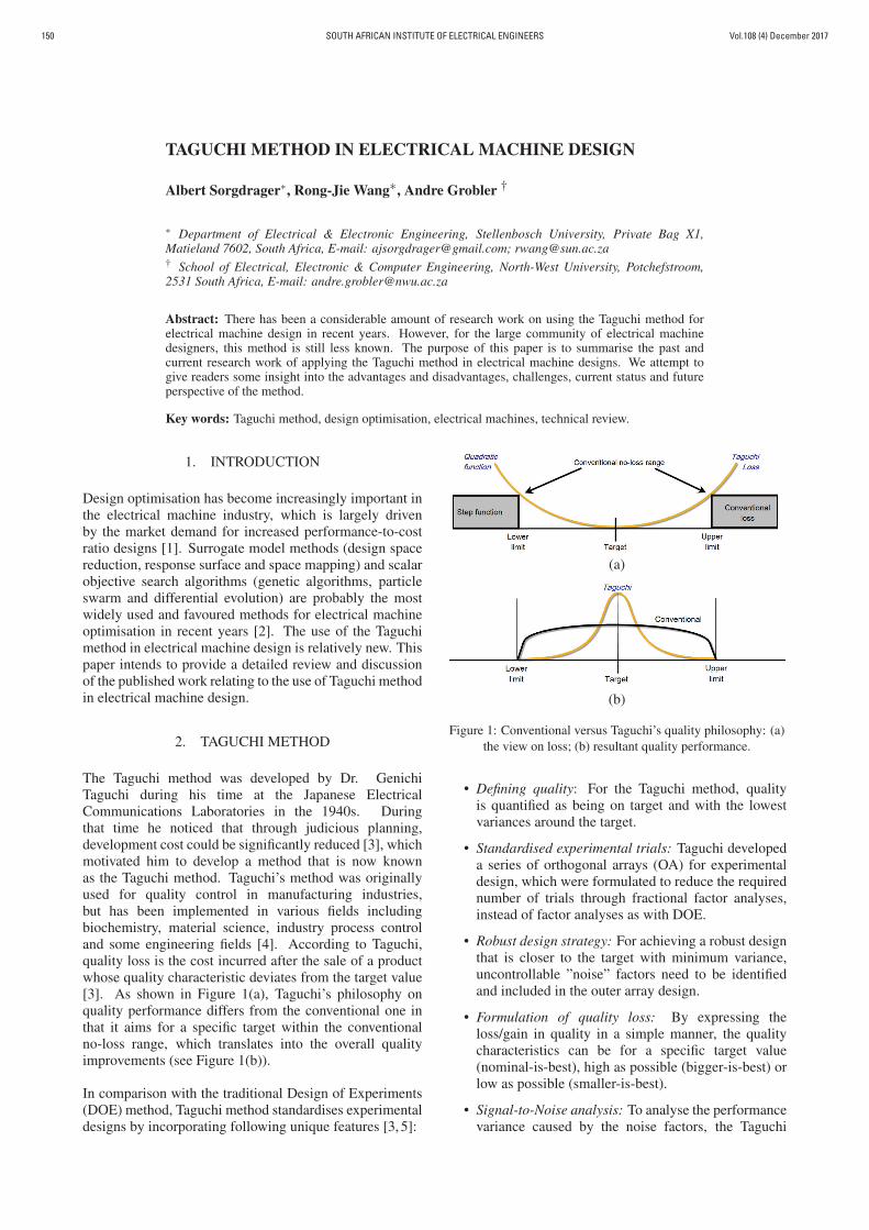
The Taguchi method was developed by Dr. GenichiTaguchi during his time at the Japanese ElectricalCommunications Laboratories in the 1940s. Duringthat time he noticed that through judicious planning,development cost could be significantly reduced [3], whichmotivated him to develop a method that is now knownas the Taguchi method. Taguchi’s method was originallyused for quality control in manufacturing industries,but has been implemented in various fields includingbiochemistry, material science, industry process controland some engineering fields [4]. According to Taguchi,quality loss is the cost incurred after the sale of a productwhose quality characteristic deviates from the target value[3]. As shown in Figure 1(a), Taguchi’s philosophy onquality performance differs from the conventional one inthat it aims for a specific target within the conventionalno-loss range, which translates into the overall qualityimprovements (see Figure 1(b)).
In comparison with the traditional Design of Experiments(DOE) method, Taguchi method standardises experimentaldesigns by incorporating following unique features [3, 5]:
(a)
(b)
Figure 1: Conventional versus Taguchi’s quality philosophy: (a)the view on loss; (b) resultant quality performance.
• Defining quality: For the Taguchi method, qualityis quantified as being on target and with the lowestvariances around the target.
• Standardised experimental trials: Taguchi developeda series of orthogonal arrays (OA) for experimentaldesign, which were formulated to reduce the requirednumber of trials through fractional factor analyses,instead of factor analyses as with DOE.
• Robust design strategy: For achieving a robust designthat is closer to the target with minimum variance,uncontrollable ”noise” factors need to be identifiedand included in the outer array design.
• Formulation of quality loss: By expressing theloss/gain in quality in a simple manner, the qualitycharacteristics can be for a specific target value(nominal-is-best), high as possible (bigger-is-best) orlow as possible (smaller-is-best).
• Signal-to-Noise analysis: To analyse the performancevariance caused by the noise factors, the Taguchi
Vol.108 (4) December 2017 SOUTH AFRICAN INSTITUTE OF ELECTRICAL ENGINEERS 151
method employs the Signal-to-Noise (S/N) ratiotransformation. This method consolidates multipledata points into a single value reflecting the amount ofvariance present for the specific quality characteristicselected.
The implementation of the Taguchi method is usuallyconducted in the following steps:
• Brainstorming and planning are seen as the mostimportant step in the Taguchi method, which focuseson the goal, problems, attributes of the parameters,experimental trials and the quality characteristics ofthe design.
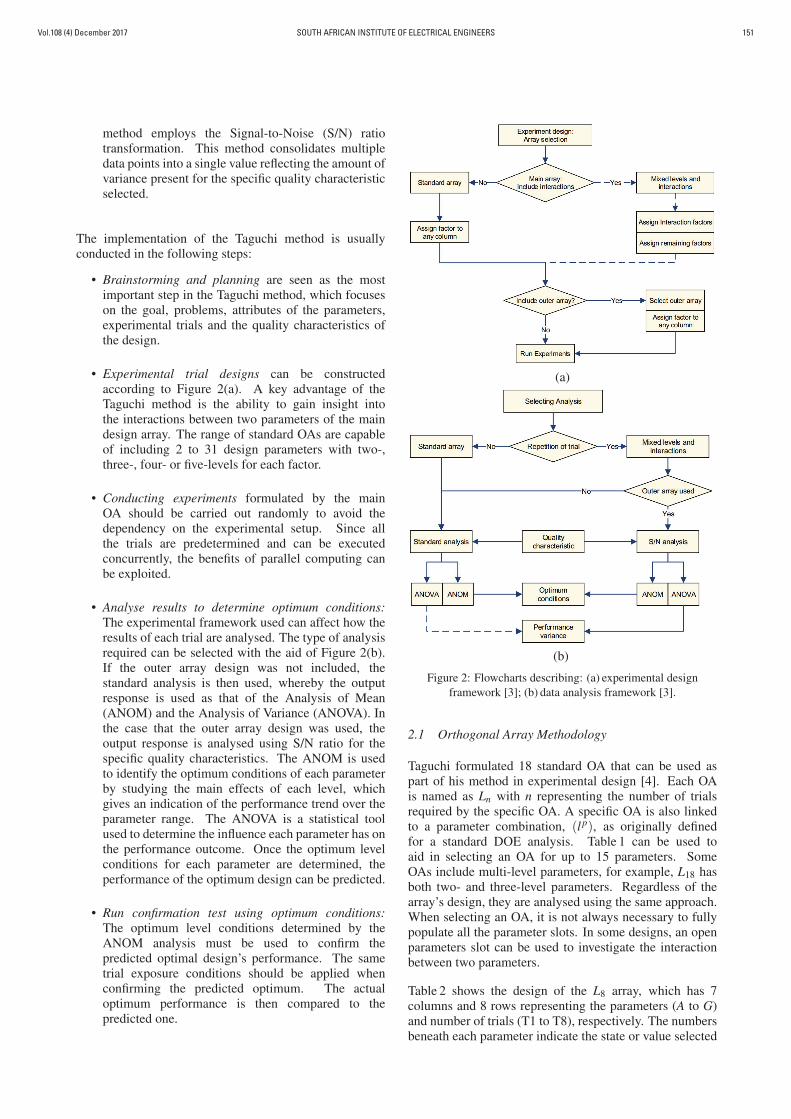
• Experimental trial designs can be constructedaccording to Figure 2(a). A key advantage of theTaguchi method is the ability to gain insight intothe interactions between two parameters of the maindesign array. The range of standard OAs are capableof including 2 to 31 design parameters with two-,three-, four- or five-levels for each factor.
• Conducting experiments formulated by the mainOA should be carried out randomly to avoid thedependency on the experimental setup. Since allthe trials are predetermined and can be executedconcurrently, the benefits of parallel computing canbe exploited.
• Analyse results to determine optimum conditions:The experimental framework used can affect how theresults of each trial are analysed. The type of analysisrequired can be selected with the aid of Figure 2(b).If the outer array design was not included, thestandard analysis is then used, whereby the outputresponse is used as that of the Analysis of Mean(ANOM) and the Analysis of Variance (ANOVA). Inthe case that the outer array design was used, theoutput response is analysed using S/N ratio for thespecific quality characteristics. The ANOM is usedto identify the optimum conditions of each parameterby studying the main effects of each level, whichgives an indication of the performance trend over theparameter range. The ANOVA is a statistical toolused to determine the influence each parameter has onthe performance outcome. Once the optimum levelconditions for each parameter are determined, theperformance of the optimum design can be predicted.
• Run confirmation test using optimum conditions:The optimum level conditions determined by theANOM analysis must be used to confirm thepredicted optimal design’s performance. The sametrial exposure conditions should be applied whenconfirming the predicted optimum. The actualoptimum performance is then compared to thepredicted one.
(a)
(b)
Figure 2: Flowcharts describing: (a) experimental designframework [3]; (b) data analysis framework [3].
2.1 Orthogonal Array Methodology
Taguchi formulated 18 standard OA that can be used aspart of his method in experimental design [4]. Each OAis named as Ln with n representing the number of trialsrequired by the specific OA. A specific OA is also linkedto a parameter combination, (l p), as originally definedfor a standard DOE analysis. Table 1 can be used toaid in selecting an OA for up to 15 parameters. SomeOAs include multi-level parameters, for example, L18 hasboth two- and three-level parameters. Regardless of thearray’s design, they are analysed using the same approach.When selecting an OA, it is not always necessary to fullypopulate all the parameter slots. In some designs, an openparameters slot can be used to investigate the interactionbetween two parameters.
Table 2 shows the design of the L8 array, which has 7columns and 8 rows representing the parameters (A to G)and number of trials (T1 to T8), respectively. The numbersbeneath each parameter indicate the state or value selected
Vol.108 (4) December 2017SOUTH AFRICAN INSTITUTE OF ELECTRICAL ENGINEERS152
Table 1: Selecting standard orthogonal arrays.
Number of parameters
Lev
els
2 3 4 5 6 7 8 9 10 11 12 13 14 15
2 L4 L4 L8 L8 L8 L8 L12 L12 L12 L12 L16 L16 L16 L16
3 L9 L9 L9 L18 L18 L18 L18 L27 L27 L27 L27 L27 L36 L36
4 L′16 L′
16 L′16 L′
16 L′32 L′
32 L′32 L′
32 L′32
5 L25 L25 L25 L25 L50 L50 L50 L50 L50 L50 L50
Table 2: Orthogonal array L8.
Parameters
L8 A B C D E F G Output
Tria
ls
T1 1 1 1 1 1 1 1 Y1
T2 1 1 1 2 2 2 2 Y2
T3 1 2 2 1 1 2 2 Y3
T4 1 2 2 2 2 1 1 Y4
T5 2 1 2 1 2 1 2 Y5
T6 2 1 2 2 1 2 1 Y6
T7 2 2 1 1 2 2 1 Y7
T8 2 2 1 2 1 1 2 Y8
to be investigated, e.g. 1 or 2 states. For any given trial,all the factors are present with their level for that specifictrial indicated in the parameters column. Within a column,the parameter has equal representation over all the trialsfor each level and is seen as balanced. In the case of anL8 array, level-1 and level-2 are each represented 4 times.For an array to be orthogonally balanced, there have to beequal occurrences of parameter combinations between anytwo columns. For the L8 there are 4 possible combinations(1,1), (1,2), (2,1) and (2,2), each occurring twice betweentwo columns. For an orthogonally balanced array, anyparameter can be placed in any column and the analysisof the results will not be affected.
Experimental design using OAs are attractive because itreduces the number of experiments and can thus reducetotal time spent. If a full factorial analysis is conductedfor the 7 two-level parameters of an L8, a total of 128experiments are required, whereas with the OA only 7experiments are needed. It should also be noted that anOA based analysis works best when there is minimumparameter interaction or inter-parameter dependency. Ifthere exists interaction between parameters, the OA stillpossesses the capability to accurately identify the optimumparameter combination. However, depending on thedegree and complexity of the parameter dependency, theremight be a difference between the predicted and actualoptimum performance. Thus, the use of a confirmation testis highly recommended under such circumstances.
3. TAGUCHI METHOD IN ELECTRICAL MACHINEDESIGN: AN OVERVIEW
3.1 Publication Overview
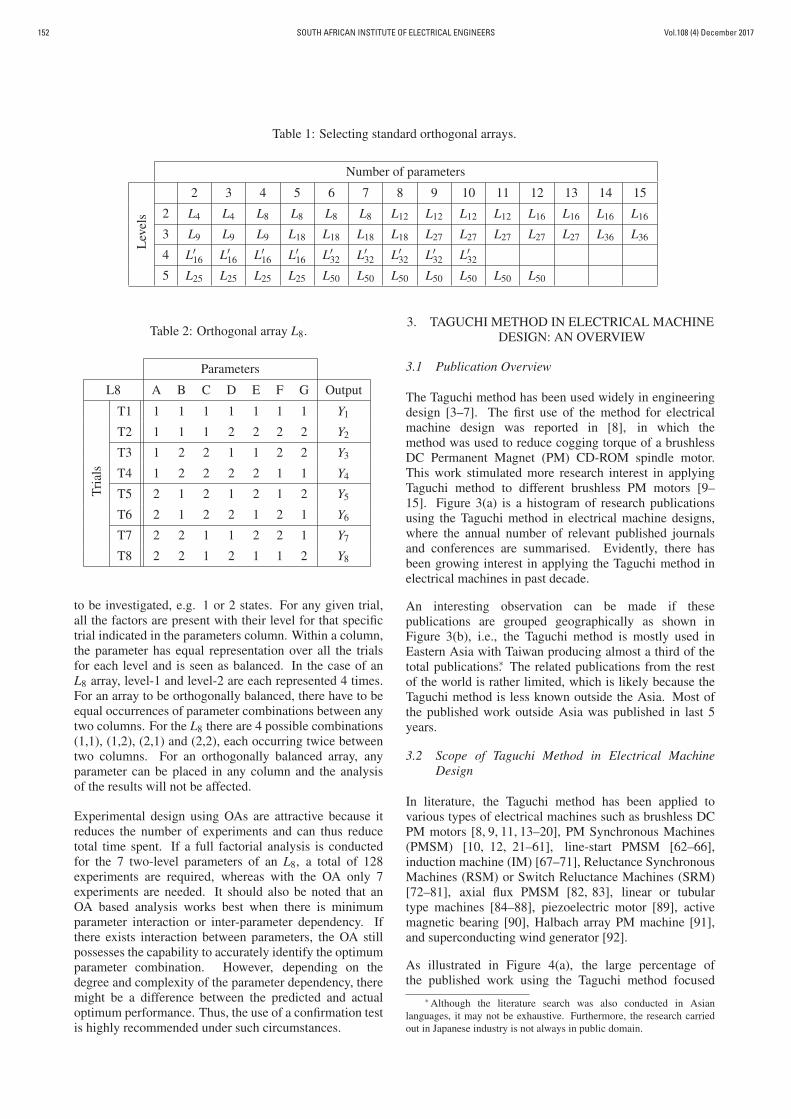
The Taguchi method has been used widely in engineeringdesign [3–7]. The first use of the method for electricalmachine design was reported in [8], in which themethod was used to reduce cogging torque of a brushlessDC Permanent Magnet (PM) CD-ROM spindle motor.This work stimulated more research interest in applyingTaguchi method to different brushless PM motors [9–15]. Figure 3(a) is a histogram of research publicationsusing the Taguchi method in electrical machine designs,where the annual number of relevant published journalsand conferences are summarised. Evidently, there hasbeen growing interest in applying the Taguchi method inelectrical machines in past decade.
An interesting observation can be made if thesepublications are grouped geographically as shown inFigure 3(b), i.e., the Taguchi method is mostly used inEastern Asia with Taiwan producing almost a third of thetotal publications∗. The related publications from the restof the world is rather limited, which is likely because theTaguchi method is less known outside the Asia. Most ofthe published work outside Asia was published in last 5years.
3.2 Scope of Taguchi Method in Electrical MachineDesign
In literature, the Taguchi method has been applied tovarious types of electrical machines such as brushless DCPM motors [8, 9, 11, 13–20], PM Synchronous Machines(PMSM) [10, 12, 21–61], line-start PMSM [62–66],induction machine (IM) [67–71], Reluctance SynchronousMachines (RSM) or Switch Reluctance Machines (SRM)[72–81], axial flux PMSM [82, 83], linear or tubulartype machines [84–88], piezoelectric motor [89], activemagnetic bearing [90], Halbach array PM machine [91],and superconducting wind generator [92].
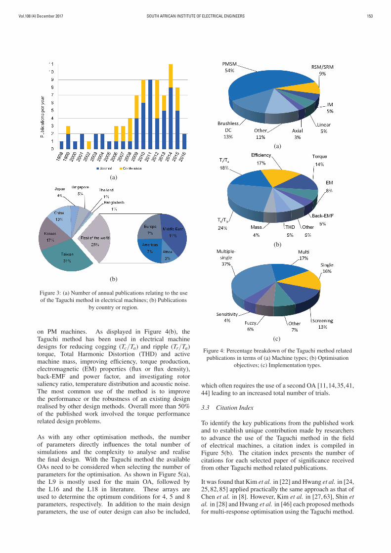
As illustrated in Figure 4(a), the large percentage ofthe published work using the Taguchi method focused
∗ Although the literature search was also conducted in Asianlanguages, it may not be exhaustive. Furthermore, the research carriedout in Japanese industry is not always in public domain.
Vol.108 (4) December 2017 SOUTH AFRICAN INSTITUTE OF ELECTRICAL ENGINEERS 153
(a)
(b)
Figure 3: (a) Number of annual publications relating to the useof the Taguchi method in electrical machines; (b) Publications
by country or region.
on PM machines. As displayed in Figure 4(b), theTaguchi method has been used in electrical machinedesigns for reducing cogging (Tc/Ta) and ripple (Tr/Ta)torque, Total Harmonic Distortion (THD) and activemachine mass, improving efficiency, torque production,electromagnetic (EM) properties (flux or flux density),back-EMF and power factor, and investigating rotorsaliency ratio, temperature distribution and acoustic noise.The most common use of the method is to improvethe performance or the robustness of an existing designrealised by other design methods. Overall more than 50%of the published work involved the torque performancerelated design problems.
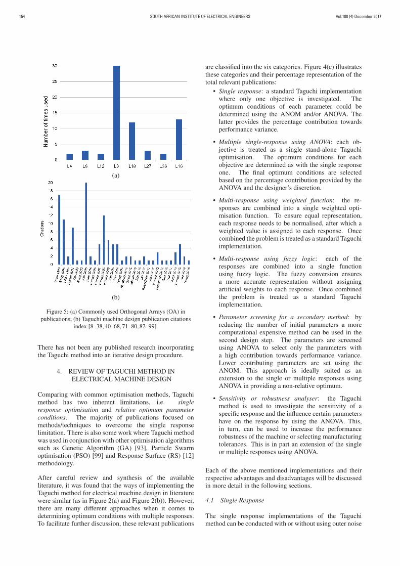
As with any other optimisation methods, the numberof parameters directly influences the total number ofsimulations and the complexity to analyse and realisethe final design. With the Taguchi method the availableOAs need to be considered when selecting the number ofparameters for the optimisation. As shown in Figure 5(a),the L9 is mostly used for the main OA, followed bythe L16 and the L18 in literature. These arrays areused to determine the optimum conditions for 4, 5 and 8parameters, respectively. In addition to the main designparameters, the use of outer design can also be included,
(a)
(b)
(c)
Figure 4: Percentage breakdown of the Taguchi method relatedpublications in terms of (a) Machine types; (b) Optimisation
objectives; (c) Implementation types.
which often requires the use of a second OA [11,14,35,41,44] leading to an increased total number of trials.
3.3 Citation Index
To identify the key publications from the published workand to establish unique contribution made by researchersto advance the use of the Taguchi method in the fieldof electrical machines, a citation index is compiled inFigure 5(b). The citation index presents the number ofcitations for each selected paper of significance receivedfrom other Taguchi method related publications.
It was found that Kim et al. in [22] and Hwang et al. in [24,25,82,85] applied practically the same approach as that ofChen et al. in [8]. However, Kim et al. in [27, 63], Shin etal. in [28] and Hwang et al. in [46] each proposed methodsfor multi-response optimisation using the Taguchi method.
Vol.108 (4) December 2017SOUTH AFRICAN INSTITUTE OF ELECTRICAL ENGINEERS154
(a)
(b)
Figure 5: (a) Commonly used Orthogonal Arrays (OA) inpublications; (b) Taguchi machine design publication citations
index [8–38, 40–68, 71–80, 82–99].
There has not been any published research incorporatingthe Taguchi method into an iterative design procedure.
4. REVIEW OF TAGUCHI METHOD INELECTRICAL MACHINE DESIGN
Comparing with common optimisation methods, Taguchimethod has two inherent limitations, i.e. singleresponse optimisation and relative optimum parameterconditions. The majority of publications focused onmethods/techniques to overcome the single responselimitation. There is also some work where Taguchi methodwas used in conjunction with other optimisation algorithmssuch as Genetic Algorithm (GA) [93], Particle Swarmoptimisation (PSO) [99] and Response Surface (RS) [12]methodology.
After careful review and synthesis of the availableliterature, it was found that the ways of implementing theTaguchi method for electrical machine design in literaturewere similar (as in Figure 2(a) and Figure 2(b)). However,there are many different approaches when it comes todetermining optimum conditions with multiple responses.To facilitate further discussion, these relevant publications
are classified into the six categories. Figure 4(c) illustratesthese categories and their percentage representation of thetotal relevant publications:
• Single response: a standard Taguchi implementationwhere only one objective is investigated. Theoptimum conditions of each parameter could bedetermined using the ANOM and/or ANOVA. Thelatter provides the percentage contribution towardsperformance variance.
• Multiple single-response using ANOVA: each ob-jective is treated as a single stand-alone Taguchioptimisation. The optimum conditions for eachobjective are determined as with the single responseone. The final optimum conditions are selectedbased on the percentage contribution provided by theANOVA and the designer’s discretion.
• Multi-response using weighted function: the re-sponses are combined into a single weighted opti-misation function. To ensure equal representation,each response needs to be normalised, after which aweighted value is assigned to each response. Oncecombined the problem is treated as a standard Taguchiimplementation.
• Multi-response using fuzzy logic: each of theresponses are combined into a single functionusing fuzzy logic. The fuzzy conversion ensuresa more accurate representation without assigningartificial weights to each response. Once combinedthe problem is treated as a standard Taguchiimplementation.
• Parameter screening for a secondary method: byreducing the number of initial parameters a morecomputational expensive method can be used in thesecond design step. The parameters are screenedusing ANOVA to select only the parameters witha high contribution towards performance variance.Lower contributing parameters are set using theANOM. This approach is ideally suited as anextension to the single or multiple responses usingANOVA in providing a non-relative optimum.
• Sensitivity or robustness analyser: the Taguchimethod is used to investigate the sensitivity of aspecific response and the influence certain parametershave on the response by using the ANOVA. This,in turn, can be used to increase the performancerobustness of the machine or selecting manufacturingtolerances. This is in part an extension of the singleor multiple responses using ANOVA.
Each of the above mentioned implementations and theirrespective advantages and disadvantages will be discussedin more detail in the following sections.
4.1 Single Response
The single response implementations of the Taguchimethod can be conducted with or without using outer noise
Vol.108 (4) December 2017 SOUTH AFRICAN INSTITUTE OF ELECTRICAL ENGINEERS 155
design such as using an outer OA or exposing the main OAto different operating conditions. Since there is only oneobjective being investigated, the working flow to analysethe data stays the same as that in Figure 2(b).
The single response Taguchi optimisation without outernoise design has been widely used in literature, which isprobably the simplest form of applying Taguchi methodas it does not require the use of Quality Control (QC),Mean-Square Deviation (MSD) and S/N ratio calculations.The optimum condition of each parameter is determinedusing the ANOM and the main effect plots. Despitethe apparent advantage of requiring fewer simulationsdue to the use of OA, the robust design feature ofthe Taguchi method is lost as the variance reduction isnot included. The use of the ANOVA is optional asthis only provides information regarding a parameter’sinfluence on performance variance. The applications ofthis approach relating to electrical machine design includeelectromagnetic design [23, 31, 54, 61, 76, 83], combinedelectrical machine and drive design [77, 79] and thermaleffects of winding potting material [78].
Azizi et al. in [76] investigated the effect that geometricalvariables have on the saliency ratio of an RSM. Thecontribution of each geometry parameter on the objectiveis examined by using the L36 OA. The ANOM andANOVA are used to determine the optimum shape of therotor to maximise the saliency ratio. An interesting aspectof the paper is the inclusion and use of the interactioneffects of the design variable in the optimisation. This wasdone by using the interaction investigation columns builtinto the OA. The interaction plots were also constructedto investigate the interaction with the most influence. Theoptimum levels were adjusted accordingly.
The first instance of using single response optimisationwith outer noise design was reported in [11], which infact was the first full implementation of Taguchi method inelectrical machine design as it applied the method strictlyaccording to Taguchi’s methodology. The aim was tominimise the cogging torque as a function of averagetorque and reduce the variance in performance caused bymanufacturing.
The Taguchi method was selected as it requires fewersimulations than DOE and traditional optimisationtechniques. Furthermore, the DOE method does not takenon-linearity or noise effects into account, thus cannotreduce performance variances. For both the main andouter arrays the L9 OA was selected, thus a total of 812D FEM simulations were required to obtain the necessaryinformation for the ANOM and ANOVA. With the use ofan outer array, a smaller-is-better MSD was calculatedfor each main trial, which are needed for the S/N ratiocalculations. The confirmation simulations showed areduction in cogging torque to average torque ratio. Thisstudy clearly demonstrated the advantages of using theTaguchi method such as the simplicity of use and theability of reducing variations when using an outer array.However, it should be noted that the use of an outer array
increases the number of simulations and in this case to thesame number as the DOE method.
The use of the Taguchi method to maximise the efficiencyof a 5 MW PM generator was presented by Tsai in[44]. The publication indicated that the Taguchi methodcan be used in a fully unconstrained machine designusing both the stator outer diameter and stack length asdesign variables. The trial machine analysis was doneusing 3D FEM simulations, after which the results wereconverted to S/N ratio to conduct the ANOM and ANOVA.The verification simulation of the optimal parametercombination confirmed the predicted performance with thefinal design realising an efficiency greater than 95% atrated conditions.
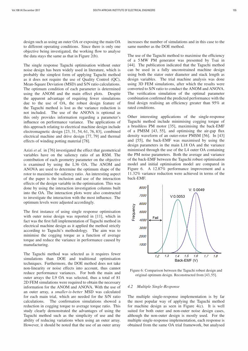
Other interesting applications of the single-responseTaguchi method include minimising cogging torque ofa brushless PM motor [35], maximising the back-EMFof a PMSM [43, 55], and optimising the air-gap fluxdensity waveform of an outer-rotor PMSM [56]. In [43]and [55], the back-EMF was maximised by using thedesign parameters in the main L18 OA and the varianceminimised through the use of the L4 outer OA containingthe PM noise parameters. Both the average and varianceof the back-EMF between the Taguchi robust optimisationmodel and initial optimisation model are compared inFigure 6. A 12.87% performance improvement and a11.32% variance reduction were achieved in terms of theback-EMF.
Figure 6: Comparison between the Taguchi robust design andoriginal optimum design. Reconstructed from [43, 55].
4.2 Multiple Single-Response
The multiple single-response implementation is by farthe most popular way of applying the Taguchi methodfor machine design as seen in Figure 4(c). It is wellsuited for both outer and non-outer noise design cases,although the non-outer design is mostly used. For themultiple single-response implementation, each response isobtained from the same OA trial framework, but analysed
Vol.108 (4) December 2017SOUTH AFRICAN INSTITUTE OF ELECTRICAL ENGINEERS156
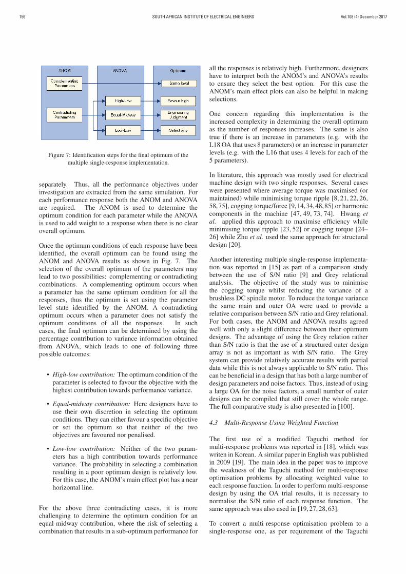
Figure 7: Identification steps for the final optimum of themultiple single-response implementation.
separately. Thus, all the performance objectives underinvestigation are extracted from the same simulation. Foreach performance response both the ANOM and ANOVAare required. The ANOM is used to determine theoptimum condition for each parameter while the ANOVAis used to add weight to a response when there is no clearoverall optimum.
Once the optimum conditions of each response have beenidentified, the overall optimum can be found using theANOM and ANOVA results as shown in Fig. 7. Theselection of the overall optimum of the parameters maylead to two possibilities: complementing or contradictingcombinations. A complementing optimum occurs whena parameter has the same optimum condition for all theresponses, thus the optimum is set using the parameterlevel state identified by the ANOM. A contradictingoptimum occurs when a parameter does not satisfy theoptimum conditions of all the responses. In suchcases, the final optimum can be determined by using thepercentage contribution to variance information obtainedfrom ANOVA, which leads to one of following threepossible outcomes:
• High-low contribution: The optimum condition of theparameter is selected to favour the objective with thehighest contribution towards performance variance.
• Equal-midway contribution: Here designers have touse their own discretion in selecting the optimumconditions. They can either favour a specific objectiveor set the optimum so that neither of the twoobjectives are favoured nor penalised.
• Low-low contribution: Neither of the two param-eters has a high contribution towards performancevariance. The probability in selecting a combinationresulting in a poor optimum design is relatively low.For this case, the ANOM’s main effect plot has a nearhorizontal line.
For the above three contradicting cases, it is morechallenging to determine the optimum condition for anequal-midway contribution, where the risk of selecting acombination that results in a sub-optimum performance for
all the responses is relatively high. Furthermore, designershave to interpret both the ANOM’s and ANOVA’s resultsto ensure they select the best option. For this case theANOM’s main effect plots can also be helpful in makingselections.
One concern regarding this implementation is theincreased complexity in determining the overall optimumas the number of responses increases. The same is alsotrue if there is an increase in parameters (e.g. with theL18 OA that uses 8 parameters) or an increase in parameterlevels (e.g. with the L16 that uses 4 levels for each of the5 parameters).
In literature, this approach was mostly used for electricalmachine design with two single responses. Several caseswere presented where average torque was maximised (ormaintained) while minimising torque ripple [8, 21, 22, 26,58,75], cogging torque/force [9,14,34,48,85] or harmoniccomponents in the machine [47, 49, 73, 74]. Hwang etal. applied this approach to maximise efficiency whileminimising torque ripple [23, 52] or cogging torque [24–26] while Zhu et al. used the same approach for structuraldesign [20].
Another interesting multiple single-response implementa-tion was reported in [15] as part of a comparison studybetween the use of S/N ratio [9] and Grey relationalanalysis. The objective of the study was to minimisethe cogging torque whilst reducing the variance of abrushless DC spindle motor. To reduce the torque variancethe same main and outer OA were used to provide arelative comparison between S/N ratio and Grey relational.For both cases, the ANOM and ANOVA results agreedwell with only a slight difference between their optimumdesigns. The advantage of using the Grey relation ratherthan S/N ratio is that the use of a structured outer designarray is not as important as with S/N ratio. The Greysystem can provide relatively accurate results with partialdata while this is not always applicable to S/N ratio. Thiscan be beneficial in a design that has both a large number ofdesign parameters and noise factors. Thus, instead of usinga large OA for the noise factors, a small number of outerdesigns can be compiled that still cover the whole range.The full comparative study is also presented in [100].
4.3 Multi-Response Using Weighted Function
The first use of a modified Taguchi method formulti-response problems was reported in [18], which waswriten in Korean. A similar paper in English was publishedin 2009 [19]. The main idea in the paper was to improvethe weakness of the Taguchi method for multi-responseoptimisation problems by allocating weighted value toeach response function. In order to perform multi-responsedesign by using the OA trial results, it is necessary tonormalise the S/N ratio of each response function. Thesame approach was also used in [19, 27, 28, 63].
To convert a multi-response optimisation problem to asingle-response one, as per requirement of the Taguchi
Vol.108 (4) December 2017 SOUTH AFRICAN INSTITUTE OF ELECTRICAL ENGINEERS 157
(a)
(b)
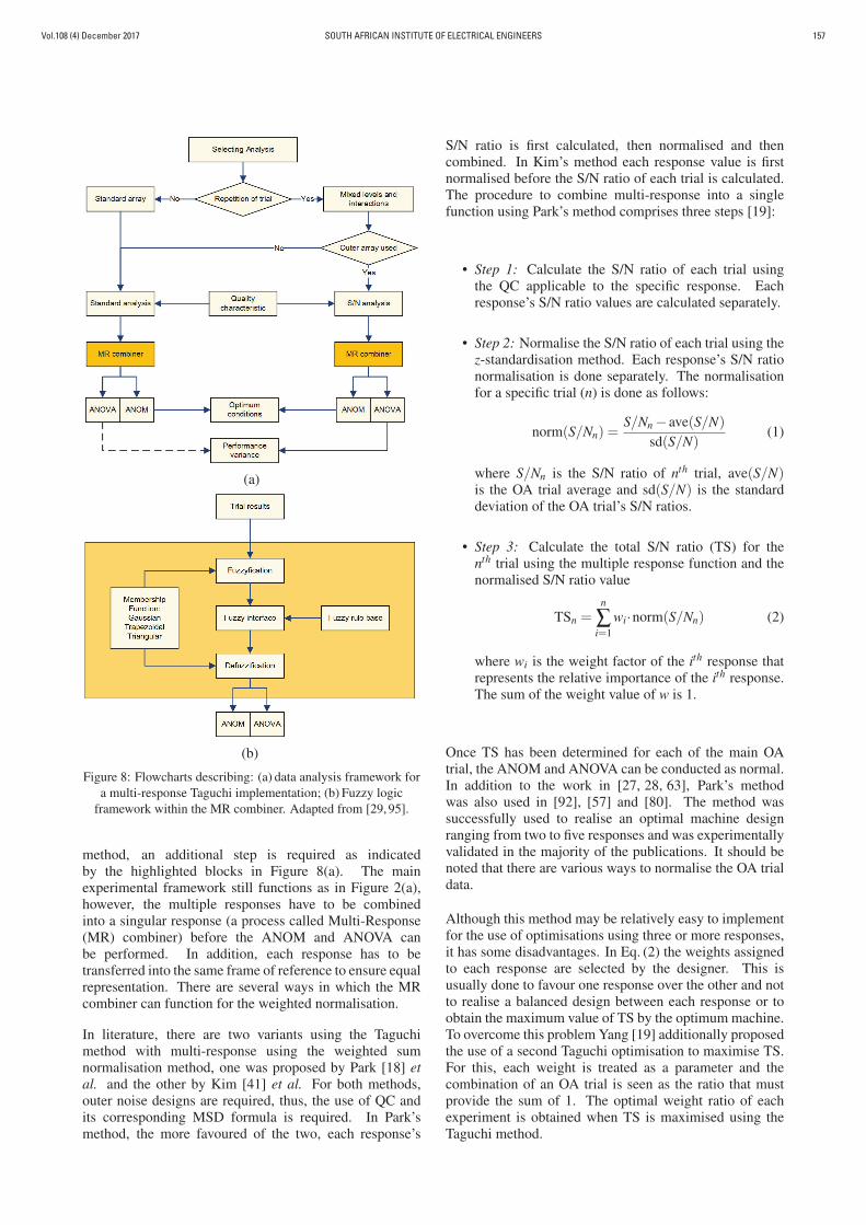
Figure 8: Flowcharts describing: (a) data analysis framework fora multi-response Taguchi implementation; (b) Fuzzy logic
framework within the MR combiner. Adapted from [29, 95].
method, an additional step is required as indicatedby the highlighted blocks in Figure 8(a). The mainexperimental framework still functions as in Figure 2(a),however, the multiple responses have to be combinedinto a singular response (a process called Multi-Response(MR) combiner) before the ANOM and ANOVA canbe performed. In addition, each response has to betransferred into the same frame of reference to ensure equalrepresentation. There are several ways in which the MRcombiner can function for the weighted normalisation.
In literature, there are two variants using the Taguchimethod with multi-response using the weighted sumnormalisation method, one was proposed by Park [18] etal. and the other by Kim [41] et al. For both methods,outer noise designs are required, thus, the use of QC andits corresponding MSD formula is required. In Park’smethod, the more favoured of the two, each response’s
S/N ratio is first calculated, then normalised and thencombined. In Kim’s method each response value is firstnormalised before the S/N ratio of each trial is calculated.The procedure to combine multi-response into a singlefunction using Park’s method comprises three steps [19]:
• Step 1: Calculate the S/N ratio of each trial usingthe QC applicable to the specific response. Eachresponse’s S/N ratio values are calculated separately.
• Step 2: Normalise the S/N ratio of each trial using thez-standardisation method. Each response’s S/N rationormalisation is done separately. The normalisationfor a specific trial (n) is done as follows:
norm(S/Nn) =S/Nn − ave(S/N)
sd(S/N)(1)
where S/Nn is the S/N ratio of nth trial, ave(S/N)is the OA trial average and sd(S/N) is the standarddeviation of the OA trial’s S/N ratios.
• Step 3: Calculate the total S/N ratio (TS) for thenth trial using the multiple response function and thenormalised S/N ratio value
TSn =n
∑i=1
wi·norm(S/Nn) (2)
where wi is the weight factor of the ith response thatrepresents the relative importance of the ith response.The sum of the weight value of w is 1.
Once TS has been determined for each of the main OAtrial, the ANOM and ANOVA can be conducted as normal.In addition to the work in [27, 28, 63], Park’s methodwas also used in [92], [57] and [80]. The method wassuccessfully used to realise an optimal machine designranging from two to five responses and was experimentallyvalidated in the majority of the publications. It should benoted that there are various ways to normalise the OA trialdata.
Although this method may be relatively easy to implementfor the use of optimisations using three or more responses,it has some disadvantages. In Eq. (2) the weights assignedto each response are selected by the designer. This isusually done to favour one response over the other and notto realise a balanced design between each response or toobtain the maximum value of TS by the optimum machine.To overcome this problem Yang [19] additionally proposedthe use of a second Taguchi optimisation to maximise TS.For this, each weight is treated as a parameter and thecombination of an OA trial is seen as the ratio that mustprovide the sum of 1. The optimal weight ratio of eachexperiment is obtained when TS is maximised using theTaguchi method.
Vol.108 (4) December 2017SOUTH AFRICAN INSTITUTE OF ELECTRICAL ENGINEERS158
4.4 Multi-Response Using Fuzzy-Logic
An alternative method when using the Taguchi methodfor multi-response optimisation is to incorporate the useof fuzzy-logic. A fuzzy-based Taguchi method was firstpublished in [29, 95] by Gaing et al., who later publishedfurther work with Chui et al. in 2014 [50]. Alsoin 2010, Hwang used a similar fuzzy base approachin [30]. In 2013, Hwang presented a comparisonstudy between a multiple single-response implementationand a fuzzy logic realised design [46]. The studyconfirmed the effectiveness of the adapted method torealise a higher performance machine design than themultiple single-response technique. The final design wasexperimentally validated. It shows that the techniquecan be applied to solve multi-response machine designoptimisation problems.
The incorporation of fuzzy-logic framework within theMR compiler block is described in Figure 8(b). Thefuzzy-based method coordinates the multiple responses toobtain the better combination of geometric parameters forachieving multiple targets using the same framework. Themethod is used primarily for pre-processing of the S/Nratios of each OA trial so that the different attributes ofeach response can be compared and summed at the samelevel by using membership functions. This ensures theidentification of the best combination of parameters by theANOM for the selected responses.
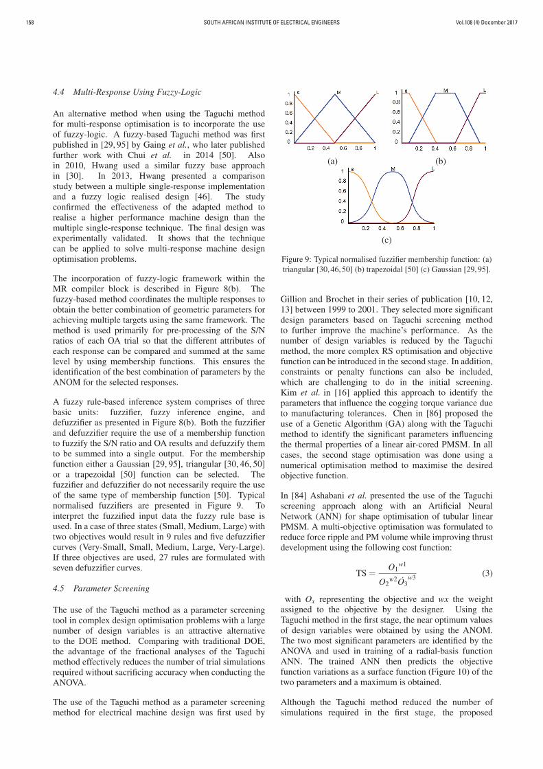
A fuzzy rule-based inference system comprises of threebasic units: fuzzifier, fuzzy inference engine, anddefuzzifier as presented in Figure 8(b). Both the fuzzifierand defuzzifier require the use of a membership functionto fuzzify the S/N ratio and OA results and defuzzify themto be summed into a single output. For the membershipfunction either a Gaussian [29, 95], triangular [30, 46, 50]or a trapezoidal [50] function can be selected. Thefuzzifier and defuzzifier do not necessarily require the useof the same type of membership function [50]. Typicalnormalised fuzzifiers are presented in Figure 9. Tointerpret the fuzzified input data the fuzzy rule base isused. In a case of three states (Small, Medium, Large) withtwo objectives would result in 9 rules and five defuzzifiercurves (Very-Small, Small, Medium, Large, Very-Large).If three objectives are used, 27 rules are formulated withseven defuzzifier curves.
4.5 Parameter Screening
The use of the Taguchi method as a parameter screeningtool in complex design optimisation problems with a largenumber of design variables is an attractive alternativeto the DOE method. Comparing with traditional DOE,the advantage of the fractional analyses of the Taguchimethod effectively reduces the number of trial simulationsrequired without sacrificing accuracy when conducting theANOVA.
The use of the Taguchi method as a parameter screeningmethod for electrical machine design was first used by
(a) (b)
(c)
Figure 9: Typical normalised fuzzifier membership function: (a)triangular [30, 46, 50] (b) trapezoidal [50] (c) Gaussian [29, 95].
Gillion and Brochet in their series of publication [10, 12,13] between 1999 to 2001. They selected more significantdesign parameters based on Taguchi screening methodto further improve the machine’s performance. As thenumber of design variables is reduced by the Taguchimethod, the more complex RS optimisation and objectivefunction can be introduced in the second stage. In addition,constraints or penalty functions can also be included,which are challenging to do in the initial screening.Kim et al. in [16] applied this approach to identify theparameters that influence the cogging torque variance dueto manufacturing tolerances. Chen in [86] proposed theuse of a Genetic Algorithm (GA) along with the Taguchimethod to identify the significant parameters influencingthe thermal properties of a linear air-cored PMSM. In allcases, the second stage optimisation was done using anumerical optimisation method to maximise the desiredobjective function.
In [84] Ashabani et al. presented the use of the Taguchiscreening approach along with an Artificial NeuralNetwork (ANN) for shape optimisation of tubular linearPMSM. A multi-objective optimisation was formulated toreduce force ripple and PM volume while improving thrustdevelopment using the following cost function:
TS =O1
w1
O2w2O3
w3 (3)
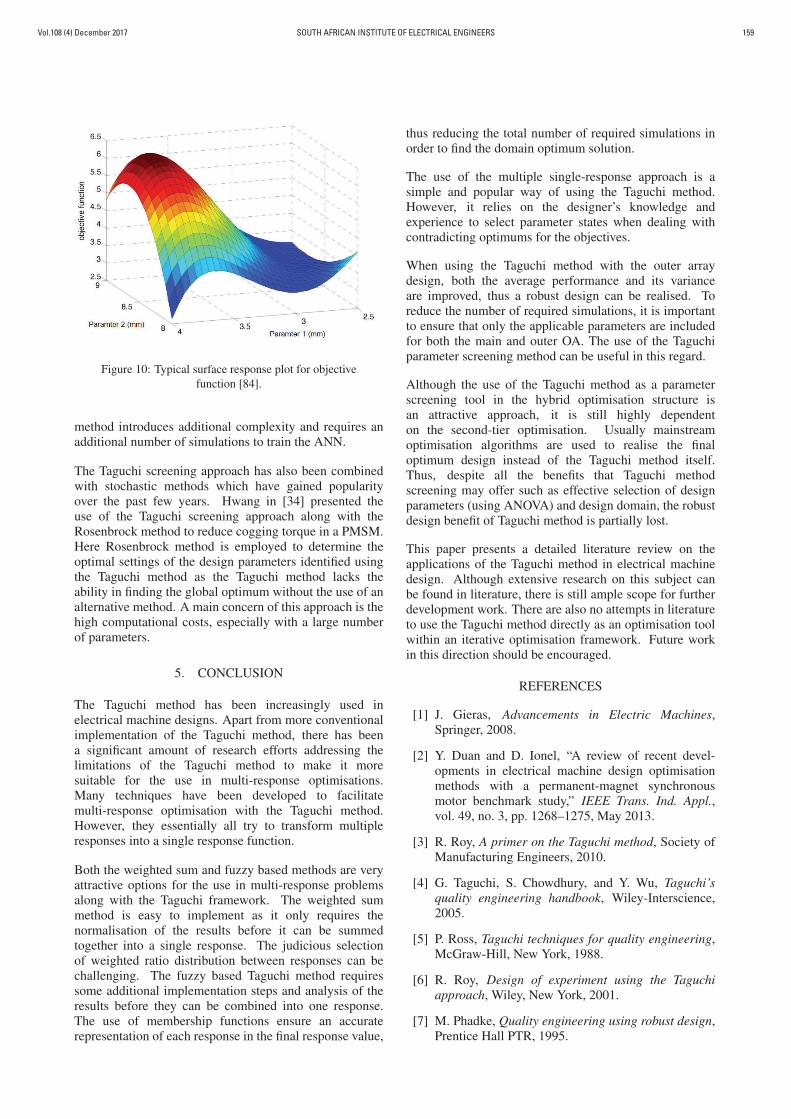
with Ox representing the objective and wx the weightassigned to the objective by the designer. Using theTaguchi method in the first stage, the near optimum valuesof design variables were obtained by using the ANOM.The two most significant parameters are identified by theANOVA and used in training of a radial-basis functionANN. The trained ANN then predicts the objectivefunction variations as a surface function (Figure 10) of thetwo parameters and a maximum is obtained.
Although the Taguchi method reduced the number ofsimulations required in the first stage, the proposed
Vol.108 (4) December 2017 SOUTH AFRICAN INSTITUTE OF ELECTRICAL ENGINEERS 159
Figure 10: Typical surface response plot for objectivefunction [84].
method introduces additional complexity and requires anadditional number of simulations to train the ANN.
The Taguchi screening approach has also been combinedwith stochastic methods which have gained popularityover the past few years. Hwang in [34] presented theuse of the Taguchi screening approach along with theRosenbrock method to reduce cogging torque in a PMSM.Here Rosenbrock method is employed to determine theoptimal settings of the design parameters identified usingthe Taguchi method as the Taguchi method lacks theability in finding the global optimum without the use of analternative method. A main concern of this approach is thehigh computational costs, especially with a large numberof parameters.
5. CONCLUSION
The Taguchi method has been increasingly used inelectrical machine designs. Apart from more conventionalimplementation of the Taguchi method, there has beena significant amount of research efforts addressing thelimitations of the Taguchi method to make it moresuitable for the use in multi-response optimisations.Many techniques have been developed to facilitatemulti-response optimisation with the Taguchi method.However, they essentially all try to transform multipleresponses into a single response function.
Both the weighted sum and fuzzy based methods are veryattractive options for the use in multi-response problemsalong with the Taguchi framework. The weighted summethod is easy to implement as it only requires thenormalisation of the results before it can be summedtogether into a single response. The judicious selectionof weighted ratio distribution between responses can bechallenging. The fuzzy based Taguchi method requiressome additional implementation steps and analysis of theresults before they can be combined into one response.The use of membership functions ensure an accuraterepresentation of each response in the final response value,
thus reducing the total number of required simulations inorder to find the domain optimum solution.
The use of the multiple single-response approach is asimple and popular way of using the Taguchi method.However, it relies on the designer’s knowledge andexperience to select parameter states when dealing withcontradicting optimums for the objectives.
When using the Taguchi method with the outer arraydesign, both the average performance and its varianceare improved, thus a robust design can be realised. Toreduce the number of required simulations, it is importantto ensure that only the applicable parameters are includedfor both the main and outer OA. The use of the Taguchiparameter screening method can be useful in this regard.
Although the use of the Taguchi method as a parameterscreening tool in the hybrid optimisation structure isan attractive approach, it is still highly dependenton the second-tier optimisation. Usually mainstreamoptimisation algorithms are used to realise the finaloptimum design instead of the Taguchi method itself.Thus, despite all the benefits that Taguchi methodscreening may offer such as effective selection of designparameters (using ANOVA) and design domain, the robustdesign benefit of Taguchi method is partially lost.
This paper presents a detailed literature review on theapplications of the Taguchi method in electrical machinedesign. Although extensive research on this subject canbe found in literature, there is still ample scope for furtherdevelopment work. There are also no attempts in literatureto use the Taguchi method directly as an optimisation toolwithin an iterative optimisation framework. Future workin this direction should be encouraged.
REFERENCES
[1] J. Gieras, Advancements in Electric Machines,Springer, 2008.
[2] Y. Duan and D. Ionel, “A review of recent devel-opments in electrical machine design optimisationmethods with a permanent-magnet synchronousmotor benchmark study,” IEEE Trans. Ind. Appl.,vol. 49, no. 3, pp. 1268–1275, May 2013.
[3] R. Roy, A primer on the Taguchi method, Society ofManufacturing Engineers, 2010.
[4] G. Taguchi, S. Chowdhury, and Y. Wu, Taguchi’squality engineering handbook, Wiley-Interscience,2005.
[5] P. Ross, Taguchi techniques for quality engineering,McGraw-Hill, New York, 1988.
[6] R. Roy, Design of experiment using the Taguchiapproach, Wiley, New York, 2001.
[7] M. Phadke, Quality engineering using robust design,Prentice Hall PTR, 1995.
Vol.108 (4) December 2017SOUTH AFRICAN INSTITUTE OF ELECTRICAL ENGINEERS160
[8] S. Chen, T. Low, and B. Bruhl, “The robust designapproach for reducing cogging torque in permanentmagnet motors [for CD-ROM spindles],” IEEETrans. Magn., vol. 34, no. 4, pp. 2135–2137, July1998.
[9] X. Gao, Z. Liu, S. Chen, and T. Low, “Optimisationand sensitivity analysis of HDD spindle motorsto manufacturing process noises using FEA andTaguchi method,” in IEEE International MagneticsConference (INTERMAG), pp. EQ06–EQ06, May1999.
[10] F. Gillon and P. Brochet, “Shape optimisation ofa permanent magnet motor using the experimentaldesign method,” IEEE Trans. Magn., vol. 35, no. 3,pp. 1278–1281, May 1999.
[11] H. Wang, Z. Liu, S. Chen, and J. Yang, “Applicationof Taguchi method to robust design of BLDC motorperformance,” IEEE Trans. Magn., vol. 35, no. 5,pp. 3700–3702, Sept. 1999.
[12] F. Gillon and P. Brochet, “Screening and responsesurface method applied to the numerical optimisationof electromagnetic devices,” IEEE Trans. Magn.,vol. 36, no. 4, pp. 1163–1167, July 2000.
[13] S. Brisset, F. Gillon, S. Vivier, and P. Brochet, “Op-timisation with experimental design: an approachusing Taguchi’s methodology and finite elementsimulations,” IEEE Trans. Magn., vol. 37, no. 5,pp. 3530–3533, Sept. 2001.
[14] T. Low, S. Chen, and X. Gao, “Robust torqueoptimisation for BLDC spindle motors,” IEEE Trans.Ind. Electron., vol. 48, no. 3, pp. 656–663, June 2001.
[15] X. Gao, Z. Liu, S. Chen, and T. Low, “Grey relationalanalysis for robust design of BLDC spindle motor,”in Digest of the Asia-Pacific Magnetic RecordingConference, Aug. 2002.
[16] Y. Kim, J. Hong, and J. Hur, “Torque characteristicanalysis considering the manufacturing tolerancefor electric machine by stochastic response surfacemethod,” IEEE Trans. Ind. Appl., vol. 39, no. 3,pp. 713–719, May 2003.
[17] Y. Kwon, J. Kim, H. Yi, and G. Park, “Optimisationof magnet pole of brushless dc motor by experimentaldesign method,” in 2006 12th Biennial IEEEConference on Electromagnetic Field Computation,pp. 470–470, 2006.
[18] H. Park, B. Yang, S. Rhee, and B. Kwon,“Novel design of flux barrier in IPM type BLDCmotor by considering the multi-response Taguchimethod,” The Transactions of The Korean Instituteof Electrical Engineers (in Korean), vol. 56, no. 3,pp. 498–505, 2007.
[19] B. Yang, K. Hwang, S. Rhee, D. Kim, andB. Kwon, “Optimisation of novel flux barrier ininterior permanent magnet-type brushless dc motorbased on modified Taguchi method,” Journal ofApplied Physics, vol. 105, no. 7, pp. 07F106, 2009.
[20] W. Zhu, X. Yang, and Z. Lan, “Structure optimisationdesign of high-speed BLDC motor using Taguchimethod,” in International Conference on Electricaland Control Engineering (ICECE), pp. 4247–4249,June 2010.
[21] Y. Okada, Y. Kawase, and S. Sano, “Developmentof optimizing method using quality engineeringand multivariate analysis based on finite elementmethod,” COMPEL-The international journal forcomputation and mathematics in electrical andelectronic engineering, vol. 23, no. 3, pp. 733–739,2004.
[22] S. Kim, J. Lee, Y. Kim, J. Hong, Y. Hur, andY. Jung, “Optimisation for reduction of torque ripplein interior permanent magnet motor by using theTaguchi method,” IEEE Trans. Magn., vol. 41, no. 5,pp. 1796–1799, May 2005.
[23] C. Hwang and T. Lin, “Design optimisation forcogging torque minimization of a high-speed 2-poleIPM machine,” in 12th Biennial IEEE Conferenceon Electromagnetic Field Computation, pp. 237–237,2006.
[24] C. Hwang, S. Cheng, and P. Li, “Design optimisationfor cogging torque minimization and efficiencymaximization of an SPM motor,” in 2007 IEEEInternational Electric Machines Drives Conference,vol. 1, pp. 642–646, May 2007.
[25] C. Hwang, L. Lyu, C. Liu, and P. Li, “Optimaldesign of an SPM motor using genetic algorithmsand Taguchi method,” IEEE Trans. Magn., vol. 44,no. 11, pp. 4325–4328, Nov. 2008.
[26] C. Hwang, C. Chang, and P. Li, “Design optimisationfor cogging torque minimization and efficiencymaximization of a high-speed PM motor,” inInternational Conference on Power Electronics andDrive Systems (PEDS), pp. 938–943, Nov. 2009.
[27] K. Kim, J. Lee, H. Kim, and D. Koo, “Multiobjectiveoptimal design for interior permanent magnetsynchronous motor,” IEEE Trans. Magn., vol. 45,no. 3, pp. 1780–1783, March 2009.
[28] D. Shin and B. Kwon, “Multi-objective optimaldesign for in-wheel permanent magnet synchronousmotor,” in International Conference on ElectricalMachines and Systems (ICEMS), pp. 1–5, Nov. 2009.
[29] Z. Gaing and J. Chiang, “Robust design of in-wheelpm motor by fuzzy-based Taguchi method,” in IEEEPES General Meeting, pp. 1–7, July 2010.
Vol.108 (4) December 2017 SOUTH AFRICAN INSTITUTE OF ELECTRICAL ENGINEERS 161
[30] C. Hwang, C. Huang, and J. Jang, “Optimaldesign and analysis of an SPM motor using fuzzyinference and Taguchi method,” in Republic of China31st Power Engineering Symposium (in Chinese),pp. 1208–1212, Dec. 2010.
[31] A. Jabbari, M. Shakeri, and A. Niaki, “Torqueripple minimization in PM synchronous motors usingtooth shape optimisation,” International Journal ofAdvanced Design and Manufacturing Technology,vol. 3, no. 2, pp. 27–31, 2011.
[32] P. Srikomkham and S. Ruangsinchaiwanich, “Op-timal rotor design of a PSC motor using Taguchimethod and FEM,” in International Conferenceon Electrical Machines and Systems (ICEMS),pp. 1341–1346, Oct. 2010.
[33] K. Abbaszadeh, F. Alam, and S. Saied,“Cogging torque optimisation in surface-mountedpermanent-magnet motors by using design ofexperiment,” Energy Conversion and Management,vol. 52, no. 10, pp. 3075–3082, 2011.
[34] C. Hwang, P. Li, C. Chang, and C. Liu,“Optimal design of an IPM motor using Taguchiand Rosenbrock’s methods,” Journal of Physics:Conference Series, vol. 266, no. 1, pp. 012069, 2011.
[35] M. Islam, R. Islam, T. Sebastian, A. Chandy, andS. Ozsoylu, “Cogging torque minimization in pmmotors using robust design approach,” IEEE Trans.Ind. Appl., vol. 47, no. 4, pp. 1661–1669, July 2011.
[36] Z. Lan, X. Yang, F. Wang, and C. Zheng,“Application for optimal designing of sinusoidalinterior permanent magnet synchronous motors byusing the Taguchi method,” Transactions of ChinaElectrotechnical Society, vol. 26, no. 12, pp. 37–42,2011.
[37] S. Rashidaee and S. Gholamian, “Reduction ofcogging torque in ipm motors by using the Taguchiand finite element method,” International Journal ofComputer Science and Engineering Survey, vol. 2,no. 2, pp. 1–10, May 2011.
[38] S. Gholamian and S. Rashidaee, “Cogging torquereduction in surface permanent magnet motorsusing Taguchi experiment design and finite elementmethod,” International Journal of Intelligent Systemsand Applications, vol. 4, no. 11, pp. 33–39, 2012.
[39] J. Hwang, C. Liu, and P. Chen, “Design ofpermanent-magnet synchronous gear motor withhigh efficiency for elevators,” in IEEE ThirdInternational Conference on Sustainable EnergyTechnologies (ICSET), pp. 205–210, Sept. 2012.
[40] M. Khan, I. Husain, R. Islam, and J. Klass,“Design of experiments to address manufacturingtolerances and process variation influencing coggingtorque and back EMF in the mass production ofthe permanent magnet synchronous motors,” in
IEEE Energy Conversion Congress and Exposition(ECCE), pp. 3032–3039, Sept. 2012.
[41] K. Kim, S. Lee, S. Cho, J. Jang, T. Lee,J. Hong, and S. Kim, “Multi-response Taguchi robustdesign of back electromotive force and coggingtorque considering the manufacturing tolerance forelectric machine,” in International Conference onoptimisation of Electrical and Electronic Equipment(OPTIM), pp. 379–387, May 2012.
[42] M. Kimura, D. Kori, A. Komura, H. Mikami, K. Ide,T. Fujigaki, M. Iizuka, and M. Fukaya, “A study ofpermanent magnet rotor for large scale wind turbinegenerator system,” in International Conference onElectrical Machines (ICEM), pp. 1161–1171, Sept.2012.
[43] S. Lee, K. Kim, S. Cho, J. Jang, T. Lee,and J. Hong, “Taguchi robust design of backelectromotive force considering the manufacturingtolerances in IPMSM,” in International Conferenceon Electromagnetic Field Problems and Applications(ICEF), pp. 1–4, June 2012.
[44] W. Tsai, “Robust design of a 5mw permanent magnetsynchronous generator using Taguchi method,”in International Conference on Computing andConvergence Technology (ICCCT), pp. 1328–1334,Dec. 2012.
[45] M. Chowdhury, M. Islam, A. Gebregergis, and T. Se-bastian, “Robust design optimisation of permanentmagnet synchronous machine utilizing genetic andTaguchi’s algorithm,” in IEEE Energy ConversionCongress and Exposition, pp. 5006–5012, Sept.2013.
[46] C. Hwang, C. Chang, and C. Liu, “A fuzzy-basedTaguchi method for multiobjective design of PMmotors,” IEEE Trans. Magn., vol. 49, no. 5,pp. 2153–2156, May 2013.
[47] M. Liu, Z. Han, Y. Pei, and P. Shi, “optimisationof permanent magnet motor air-gap flux densitybased on the non-uniform air gap,” in InternationalConference on Mechatronic Sciences, ElectricEngineering and Computer, pp. 3422–3426, Dec.2013.
[48] A. Shirazi1, B. Yousefi, S. Gholamian, andS. Rashidaee, “Application of Taguchi experimentdesign for decrease of cogging torque in permanentmagnet motors,” International Journal on Compu-tational Sciences and Applications, vol. 3, no. 2,pp. 31–38, 2013.
[49] M. Beniakar, P. Kakosimos, C. Krasopoulos,A. Sarigiannidis, and A. Kladas, “Comparison ofin-wheel permanent magnet motors for electrictraction,” in Electrical Machines (ICEM), 2014International Conference on, pp. 2472–2478, Sept.2014.
Vol.108 (4) December 2017SOUTH AFRICAN INSTITUTE OF ELECTRICAL ENGINEERS162
[50] M. Chui, J. Chiang, J. Lee, and Z. Gaing,“Multi-objective optimisation design of interiorpermanent-magnet synchronous motors for improv-ing the effectiveness of field weakening control,”in Int. Conf. on Electrical Machines and Systems(ICEMS), pp. 517–521, Oct. 2014.
[51] J. Cui, W. Xiao, L. Wang, H. Feng, J. Zhao,and H. Wang, “optimisation design of low-speedsurface-mounted PMSM for pumping unit,” Inter-national Journal of Applied Electromagnetics andMechanics, vol. 46, no. 1, pp. 217–228, 2014.
[52] C. Hwang, S. Hung, C. Liu, and S. Cheng, “Optimaldesign of a high speed SPM motor for machine toolapplications,” IEEE Trans. Magn., vol. 50, no. 1,pp. 1–4, Jan. 2014.
[53] M. Khan, I. Husain, M. Islam, and J. Klass,“Design of experiments to address manufacturingtolerances and process variations influencing coggingtorque and back EMF in the mass production ofthe permanent-magnet synchronous motors,” IEEETrans. Ind. Appl., vol. 50, no. 1, pp. 346–355, Jan.2014.
[54] K. Kim, “A novel method for minimization ofcogging torque and torque ripple for interiorpermanent magnet synchronous motor,” IEEE Trans.Magn., vol. 50, no. 2, pp. 793–796, Feb. 2014.
[55] S. Lee, K. Kim, S. Cho, J. Jang, T. Lee, and J. Hong,“Optimal design of interior permanent magnetsynchronous motor considering the manufacturingtolerances using Taguchi robust design,” IET ElectricPower Applications, vol. 8, no. 1, pp. 23–28, Jan.2014.
[56] S. Lee, K. Kim, S. Cho, J. Jang, T. Lee, and J. Hong,“Optimal design of the magnetizing fixture usingTaguchi robust design in the ring-type PMSM,” inIET International Conference on Power Electronics,Machines and Drives (PEMD), pp. 1–6, April 2014.
[57] D. Misu, M. Matsushita, K. Takeuchi, K. Oishi, andM. Kawamura, “Consideration of optimal number ofpoles and frequency for high-efficiency permanentmagnet motor,” in International Power ElectronicsConference (IPEC), pp. 3012–3017, May 2014.
[58] W. Ren, Q. Xu, and Q. Li, “Asymmetrical V-shaperotor configuration of an interior permanent magnetmachine for improving torque characteristics,” IEEETrans. Magn., vol. 51, no. 11, pp. 1–4, Nov. 2015.
[59] C. Xia, L. Guo, Z. Zhang, T. Shi, and H. Wang,“Optimal designing of permanent magnet cavityto reduce iron loss of interior permanent magnetmachine,” IEEE Trans. Magn., vol. 51, no. 12,pp. 1–9, Dec. 2015.
[60] Z. Xu, S. Wang, Z. Zhang, T. Chin, andC. Sung, “optimisation of magnetizing parametersfor multipole magnetic scales using the Taguchi
method,” IEEE Trans. Magn., vol. 51, no. 11, pp. 1–4,Nov. 2015.
[61] M. Vukotic and D. Miljavec, “Design of apermanent-magnet flux-modulated machine witha high torque density and high power factor,”IET Electric Power Applications, vol. 10, no. 1,pp. 36–44, 2016.
[62] B. Ahn, W. Kim, B. Kim, K. Ko, and J. Lee, “Astudy on the optimal barrier design for high efficiencyof LSPM,” in International Conference on ElectricalMachines and Systems (ICEMS), pp. 3427–3429, Oct2008.
[63] W. Kim, K. Kim, S. Kim, D. Kang, S. Go, H. Lee,Y. Chun, and J. Lee, “A study on the optimalrotor design of LSPM considering the starting torqueand efficiency,” IEEE Trans. Magn., vol. 45, no. 3,pp. 1808–1811, March 2009.
[64] A. Sorgdrager, R. Wang, and A. Grobler, “Retrofitdesign of a line-start PMSM using the Taguchimethod,” in IEEE Int. Electric Machines Drives Conf.(IEMDC), pp. 489–495, May 2015.
[65] A. Sorgdrager, R. Wang, and A. Grobler, “Transientperformance investigation and Taguchi optimisationof a line-start PMSM,” in IEEE Int. ElectricMachines Drives Conf. (IEMDC), pp. 590–595, May2015.
[66] A. Sorgdrager, R. Smith, and R. Wang, “Rotordesign of a line-start permanent magnet synchronousmachine using the Taguchi method,” in Proc.of the 23rd Southern African Universities PowerEngineering Conference, pp. 227-232, Jan. 2015.
[67] M. Gracia and K. Hameyer, “Multi-objectiveoptimisation of an induction machine using designof experiments,” in IEEE Conference on Electromag-netic Field Computation, pp. 327-327, May 2008.
[68] K. Park, K. Kim, S. Lee, D. Koo, K. Ko, and J. Lee,“Optimal design of rotor slot of three phase inductionmotor with die-cast copper rotor cage,” in Int. Conf.on Electrical Machines and Systems (ICEMS), Oct.2008, pp. 61–63.
[69] T. Minari, Y. Fujino, Y. Takeshima, and K. Mizutani,“Development of high efficiency induction motor byusing Taguchi method,” Sumitomo Heavy IndustriesTechnical Review (in Japanese), Tech. Rep., 2012.
[70] K. Mizutani, T. Minari, and T. Mineo, “Developmentof IE3 premium efficiency motor,” Sumitomo HeavyIndustries Technical Review (in Japanese), Tech.Rep., 2014.
[71] C. Lin and C. Hwang, “Multiobjective optimisationdesign for a six-phase copper rotor induction motormounted with a scroll compressor,” IEEE Trans.Magn., vol. 52, no. 7, pp. 9401604, 2016.
Vol.108 (4) December 2017 SOUTH AFRICAN INSTITUTE OF ELECTRICAL ENGINEERS 163
[72] A. Omekanda, “Robust torque and torque-per-inertiaoptimisation of a switched reluctance motor using theTaguchi methods,” IEEE Trans. Ind. Appl., vol. 42,no. 2, pp. 473–478, March 2006.
[73] L. Ji and X. Yang, “Optimisation design on salientpole rotor of BDFRM using the Taguchi method,” inPower Electronics Systems and Applications (PESA),2011 4th International Conference on, pp. 1–4, June2011.
[74] S. Gong, X. Yang, and L. Ji, “Parameterscalculation and optimized design for brushlessdoubly-fed reluctance machine,” in Int. Conf. onPower Electronics Systems and Applications (PESA),pp. 1–4, June 2011.
[75] M. Tavakkoli and M. Moallem, “Torque ripplemitigation of double stator switched reluctance motor(DSSRM) using a novel rotor shape optimisation,”in 2012 IEEE Energy Conversion Congress andExposition (ECCE), pp. 848–852, Sept. 2012.
[76] H. Azizi and A. Vahedi, “Rotor geometry param-eter optimisation of synchronous reluctance motorusing Taguchi method,” Przeglad Elektrotechniczny,vol. 89, no. 12, pp. 197–201, 2013.
[77] Z. Gaing, Y. Hsiah, M. Tsai, M. Hsieh, andM. Tsai, “Hybrid design model for optimal designingof a switched reluctance motor,” in Int. Conf.on Electrical Machines and Systems (ICEMS),pp. 505–510, Oct. 2013.
[78] J. Wang, S. Kim, and N. Kim, “A study onthe bearingless switched reluctance rotation motorwith improved motor performance,” Journal ofMechanical Science and Technology, vol. 27, no. 5,pp. 1407–1414, 2013.
[79] Z. Gaing, K. Kuo, J. Hu, M. Hsieh, and M. Tsai,“Design and optimisation of high-speed switchedreluctance motor using soft magnetic compositematerial,” in International Power Electronics Confer-ence (IPEC), pp. 278–282, May 2014.
[80] H. Azizi and A. Vahedi, “Sensitivity analysis andoptimum design for the stator of synchronousreluctance machines using the coupled finite elementand Taguchi methods,” Turkish Journal of ElectricalEngineering and Computer Sciences, vol. 23, no. 1,pp. 38–51, 2015.
[81] K. Deguchi, S. Sumita, and Y. Enomoto, “An-alytical method applying a mathematical modelfor axial-gap-switched reluctance motor,” ElectricalEngineering in Japan, vol. 196, no. 3, pp. 30–38,2016.
[82] C. Hwang, P. Li, F. Chuang, C. Liu, and K. Huang,“Optimisation for reduction of torque ripple in anaxial flux permanent magnet machine,” IEEE Trans.Magn., vol. 45, no. 3, pp. 1760–1763, March 2009.
[83] U. Kurt, G. Onbilgin, “Design and optimisation ofaxial flux permanent magnet synchronous machinesusing Taguchi approach,” in International Confer-ence on Electrical and Electronics Engineering,pp. 202–205, Nov. 2009.
[84] M. Ashabani, Y. Mohamed, and J. Milimonfared,“Optimum design of tubular permanent-magnetmotors for thrust characteristics improvement bycombined Taguchi neural network approach,” IEEETrans. Magn., vol. 46, no. 12, pp. 4092–4100, Dec.2010.
[85] C. Hwang, P. Li, and C. Liu, “Optimal design ofa permanent magnet linear synchronous motor withlow cogging force,” IEEE Trans. Magn., vol. 48,no. 2, pp. 1039–1042, Feb. 2012.
[86] W. Chen, J. Lin, D. Chen, and F. Nian, “Optimi-sation design of a Taguchi-based real-code geneticalgorithm for thermal reducing of air-core linearbrushless permanent magnet motor,” InternationalJournal of Modeling and optimisation, vol. 4, no. 5,pp. 402–409, Oct. 2014.
[87] C. Hsiao, S. Yeh, and J. Hwang, “Design of highperformance permanent-magnet synchronous windgenerators,” Energies, vol. 7, no. 11, pp. 7105–7124,2014.
[88] W. Tseng, C. Kuo, and L. Su, “Optimizing designparameters of a novel PM transverse flux linearmotor,” Transactions of the Canadian Society forMechanical Engineering, vol. 39, no. 3, pp. 443–454,2015.
[89] Y. Ting, J. Huang, F. Chuang, and C. Li, “Dynamicanalysis and optimal design of a piezoelectric motor,”IEEE Trans. Ultrason., Ferroelect., Freq. Control,vol. 50, no. 6, pp. 601–613, June 2003.
[90] S. Seo, M. Lee, S. Kim, and N. Kim, “Robustoptimum design of a bearing-less rotation motorusing the Kriging model,” International Journal ofPrecision Engineering and Manufacturing, vol. 12,no. 6, pp. 1043–1050, 2011.
[91] T. Shi, Z. Qiao, C. Xia, H. Li, and Z. Song,“Modeling, analyzing, and parameter design of themagnetic field of a segmented Halbach cylinder,”IEEE Trans. Magn., vol. 48, no. 5, pp. 1890–1898,May 2012.
[92] H. Sung, G. Kim, K. Kim, S. Jung, M. Park,I. Yu, Y. Kim, H. Lee, and A. Kim, “Practicaldesign of a 10 MW superconducting wind powergenerator considering weight issue,” IEEE Trans.Appl. Supercond., vol. 23, no. 3, pp. 5201805, June2013.
[93] J. Tsai, T. Liu, and J. Chou, “Hybrid Taguchi-geneticalgorithm for global numerical optimisation,” IEEETrans. Evolutionary Computation, vol. 8, no. 4,pp. 365–377, Aug. 2004.
Vol.108 (4) December 2017SOUTH AFRICAN INSTITUTE OF ELECTRICAL ENGINEERS164
[94] P. Chatsirirungruang, “Application of genetic al-gorithm and Taguchi method in dynamic robustparameter design for unknown problems,” The Int.Journal of Advanced Manufacturing Technology,vol. 47, no. 9-12, pp. 993–1002, 2010.
[95] Z. Gaing, Q. Wang, and J. Chiang, “optimisationof in-wheel pm motor by fuzzy-based Taguchimethod,” in Int. Power Electronics Conf. (IPEC),pp. 1312–1316, June 2010.
[96] X. Wu and G. Zhou, “Application of improvedTaguchi method to the multi-response optimisation,”in IEEE Int. Conf. on Industrial Engineering &Engineering Management, Part 3, pp. 1829–1832,Sept. 2011.
[97] S. Wang and T. Chueh, “Research of permanentmagnetic brushless motor on epoxy resin withTaguchi method,” in Int. Conf. on Consumer Elec-
tronics, Communications and Networks (CECNet),pp. 3423–3424, April 2012,
[98] J. Kuo and M. Chang, “Multiobjective designof turbo injection mode for axial flux motorin plastic injection molding machine by particleswarm optimisation,” Mathematical Problems inEngineering, 11 pages, 2015.
[99] H. Wang, Q. Geng, and Z. Qiao, “Parameter tuningof particle swarm optimisation by using Taguchimethod and its application to motor design,” in IEEEInt. Conf. on Information Science & Technology,pp. 722–726, April 2014.
[100] X. Gao, “Robust design of miniaturised spindlemotors for hard disk drive,” Ph.D. dissertation,Electrical and Computer Engineering at the NationalUniversity of Singapore, 2002.