tag switching on cisco 7000 family - ku ittc switching on cisco 7000 family 1 tag switching on cisco...
TRANSCRIPT
Tag Switching on Cisco 7000 Family 1
Tag Switching on Cisco 7000 Family
Feature SummaryTag Switching combines the performance and capabilities of Layer 2 (data link layer) switching withthe proven scalability of Layer 3 (network layer) routing. It enables service providers to meetchallenges brought about by explosive growth and provides the opportunity for differentiatedservices without necessitating the sacrifice of existing infrastructure. The Tag Switching architectureis remarkable for its flexibility. Data can be transferred over any combination of Layer 2technologies, support is offered for all Layer 3 protocols, and scaling is possible well beyondanything offered in today’s networks.
Specifically Tag Switching can efficiently enable the delivery of IP services over an ATM switchednetwork. It supports the creation of different routes between a source and a destination on a purelyrouter-based Internet backbone. Service providers who use Tag Switching can save money andincrease revenue and productivity.
BenefitsTag Switching offers the following benefits:
• IP over ATM scalability—Enables service providers to keep up with Internet growth
• IP services over ATM—Brings Layer 2 benefits to Layer 3, such as traffic engineering capability
• Standards—Supports multivendor solutions
• Architectural flexibility—Offers choice of ATM or router technology, or a mix of both
List of TermsATM-TSR —A Tag Switching router with a number of TC-ATM interfaces. The router forwards thecells among these interfaces using tags carried in the VPI/VCI field.
ATM edge TSR—A router that is connected to the ATM-TSR cloud through TC-ATM interfaces.The ATM edge TSR adds tags to untagged packets and strips tags from tagged packets.
forwarding equivalence class—A set of packets, which, however different they may be, areindistinguishable to the forwarding function.
headend—The upstream, transmit end of a tunnel.
tag—A short fixed-length label that tells switching nodes how the data (packets or cells) should beforwarded.
tag imposition—The act of putting the first tag on a packet.
Feature Summary
2 Cisco IOS Release 11.1CT
tag edge router—The router that performs tag imposition.
Tag Switch—A node that forwards units of data (packets or cells) on the basis of tags.
tag-switched path (TSP)—A sequence of hops (R0...Rn) in which a packet travels from R0 to Rnthrough Tag Switching mechanisms. A tag-switched path can be chosen dynamically, based onnormal routing mechanisms, or through configuration.
Tag Switching Router (TSR)—A Layer 3 router that forwards packets based on the value of a tagencapsulated in the packets.
tailend—The downstream, receive end of a tunnel.
TDP—Tag Distribution Protocol. The protocol used to distribute tag bindings on TSRs.
TFIB —Tag Forwarding Information Base. The data structure used by the switching function toswitch tagged packets.
TIB —Tag Information Base. A database used to store tags learned from other TSRs as well as tagsassigned by the local TSR.
traffic engineering—The techniques and processes used to cause routed traffic to travel through thenetwork on a path other than the one that would have been chosen if standard routing methods hadbeen used.
traffic engineering tunnel— A tag-switched path tunnel that is used for engineering traffic. It is setup through means other than normal Layer 3 routing and is used to direct traffic over a path differentfrom the one that Layer 3 routing would cause it to take.
tag-switched path (TSP) tunnel—A configured connection between two routers, using TagSwitching to carry the packets.
Tag VC (TVC)—An ATM virtual circuit that is set up through ATM TSR tag distributionprocedures.
tag-controlled ATM interface (TC-ATM interface)— An interface on a router or switch that usestag distribution procedures to negotiate tag VCs.
RestrictionsTag Switching on the router requires that Cisco Express Forwarding (CEF) be enabled. Refer to theCisco Express Forwarding(CEF) feature documentation for configuration information.
Memory RequirementsThe recommended minimum memory requirement in platforms carrying full Internet routinginformation is the same as for Cisco Express Forwarding. For more details, see the Release Notesfor Cisco IOS 11.1 CC and Feature Modules.
Platforms
Tag Switching on Cisco 7000 Family 3
PlatformsTag switching is supported on the following platforms:
• Cisco 7500 series routers
• Cisco 7200 series router
• Cisco RSP7000
• Cisco LightStream 1010 ATM switches1
Supported MediaThe interfaces supported are
• ATM Interface Processor (AIP)
• ATM Port Adapter (PA-A1)
• Enhanced 4-Port Synchronous Serial Port Adapter (PA-4T+)
• Ethernet Interface Processor (EIP)
• Fast Ethernet Interface Processor (FEIP)
• Four-port Ethernet Port Adapter (4EPA)
• Fast Ethernet Port Adapter (PA-FE)
• HSSI Interface Processor (HIP)
• Packet Over SONET Interface Processor (POSIP)
• One-port High-Speed Serial Interface (HSSI) Port Adapter (PA-H)
• Synchronous Serial EIA/TIA-232 Port Adapter (PA-8T-232)
• Synchronous Serial V.35 Port Adapter (PA-8T-V35)
• Synchronous Serial X.21 Port Adapter (PA-8T-X21)
• Two-port HSSI Port Adapter (PA-2H)
Note ATM interfaces can support either packet tagging over permanent virtual circuits (PVCs) orATM tagging where the value in the virtual circuit (VC) field is used as a tag.
Supported MIBs and RFCsThis feature supports RFC 2105, Cisco Systems’ Tag Switching Architectural Overview.
Functional DescriptionTag switching is a high-performance packet forwarding technology. It integrates the performanceand traffic management capabilities of data link layer (Layer 2) switching with the scalability andflexibility of network layer (Layer 3) routing.
1. For information about Tag Switching configuration and command syntax on the LightStream 1010 ATM switch, see theLightStream 1010 ATM Switch Software Configuration Guide Release 11.3.
Functional Description
4 Cisco IOS Release 11.1CT
Tag FunctionsIn conventional Layer 3 forwarding, as a packet traverses the network, each router extracts all theinformation relevant to forwarding the packet from the Layer 3 header. This information is then usedas an index for a routing table lookup to determine the packet's next hop.
In the most common case, the only relevant field in the header is the destination address field, but insome cases other header fields may also be relevant. As a result, the header analysis must be doneindependently at each router through which the packet passes, and a complicated lookup must alsobe done at each router.
In Tag Switching, the analysis of the Layer 3 header is done just once. The Layer 3 header is thenmapped into a fixed length, unstructured value called atag.
Many different headers can map to the same tag, as long as those headers always result in the samechoice of next hop. In effect, a tag represents aforwarding equivalence class—that is, a set ofpackets, which, however different they may be, are indistinguishable to the forwarding function.
The initial choice of tag need not be based exclusively on the contents of the Layer 3 header; it canalso be based on policy. This allows forwarding decisions at subsequent hops to be based on policyas well.
Once a tag is chosen, a short tag header is put at the front of the Layer 3 packet, so that the tag valuecan be carried across the network with the packet. At each subsequent hop, the forwarding decisioncan be made simply by looking up the tag. There is no need to re-analyze the header. Since the tagis a fixed length and unstructured value, looking it up is fast and simple.
Distribution of Tag BindingsEachtag switching router(TSR) makes an independent, local decision as to which tag value is usedto represent which forwarding equivalence class. This association is known as a tag binding. EachTSR informs its neighbors of the tag bindings it has made. This is done by means of the TagDistribution Protocol (TDP).
When a tagged packet is being sent from TSR A to a neighboring TSR B, the tag value carried bythe packet is the tag value that B assigned to represent the packet's forwarding equivalence class.Thus the tag value changes as the packet travels through the network.
Tag Switching and RoutingA tag represents a forwarding equivalence class, but it does not represent a particular path throughthe network. In general, the path through the network continues to be chosen by the existingLayer 3 routing algorithms such as OSPF, EIGRP, and BGP. That is, at each hop when a tag is lookedup, the next hop chosen is determined by the dynamic routing algorithm.
Tag Switching and Traffic EngineeringIn conventional Layer 3 routing, network topologies frequently include multiple paths between twopoints, but the normal routing procedure is to select a single path as the Layer 3 route between twopoints regardless of the load on the links that implement the path. As a consequence, some links arecongested and some are underused.
Traffic engineeringprovides a way to override routing protocols across multiple routers. It gives youthe ability to direct selected traffic over specific paths in the network in order to efficiently usenetwork resources and provide different levels of service.

Functional Description
Tag Switching on Cisco 7000 Family 5
To engineer your network traffic, you follow a two-step process. First, you define a sequence of linksbetween two routers. Tag switching is used to tunnel packets between the two routers over theselinks. The links collectively form atag switched path (TSP) tunnel, which defines a trafficengineering path. Second, you select the traffic which you want forwarded on to the tunnel.
Traffic Engineering Tunnels and FiltersThe traffic to be engineered is specified by a traffic engineering filter. The filter is associated with aTSP tunnel using a traffic engineering path.
The router at the head of the tunnel arranges that packets that match the filter be injected into thetunnel rather than being forwarded to their Layer 3 next hop. Injection consists simply of sendingthe packet to the first hop in the tunnel with a tag that causes that first hop to send the packet to thesecond hop of the tunnel, and so on.
For the initial release of traffic engineering, the only supported filtering is by “egress address.” Thisfilter matches traffic whose destination or BGP next hop is “address.”
Multiple tunnels with different preferences can be specified for a single filter. A preference is anoption you can select among multiple candidate routes for a filter, with the lower-valued preferencebeing more desirable. The most preferred of the acceptable tunnels is used for the traffic.
A loop prevention algorithm operates to ensure that a tunnel is not used for traffic that might loopback to the head of the tunnel.
Traffic Engineering Tunnel ConfigurationConfiguration and the initiation of the tunnel are controlled by theheadend (transmit end) router.Per-tunnel configuration of other routers is unnecessary.
Routers create and maintain thetraffic engineering tunnelsbased on information you enter throughthe command line interface (CLI). See the section called “Command Reference.”

Configuration Tasks
6 Cisco IOS Release 11.1CT
Configuration TasksThis section describes three sample cases where Tag Switching is configured on Cisco 7500/7200series routers. These cases show the levels of control possible in selecting how Tag Switching isdeployed in a network.
Table 1 lists the cases, including the steps to perform Tag Switching and their corresponding CiscoIOS CLI commands.
Table 1 Tag Switching—Levels of Control
For more information about the IOS CLI commands, see the section called “Command Reference.”
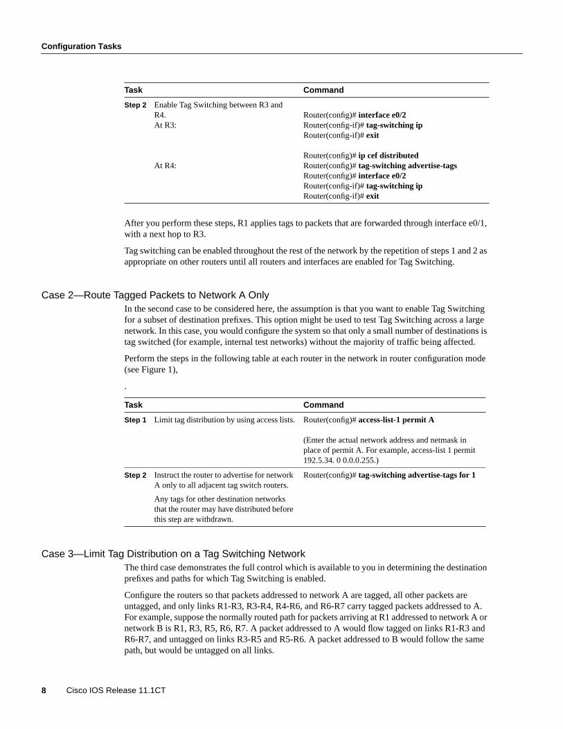
Figure 1 shows a router-only Tag Switching network with Ethernet interfaces. The followingsections outline the procedures for configuring Tag Switching and displaying Tag Switchinginformation in a network based on the topology shown in Figure 1.
Note Ethernet interfaces are shown in Figure 1, but any of the interfaces listed in the “SupportedMedia” section could be used instead. ATM interfaces operating as TC-ATM interfaces are theexception to this statement.
This case Describes
Case 1—Enable Tag Switching Incrementallyin a Network
The steps necessary for incrementally deployingTag Switching through a network, assuming thatpackets to all destination prefixes should be tagswitched.
Case 2—Route Tagged Packets to Network AOnly
The mechanism by which Tag Switching can berestricted, such that packets are tag switched to onlya subset of destinations.
Case 3—Limit Tag Distribution on a TagSwitching Network
The mechanisms for further controlling thedistribution of tag within a network.

Configuration Tasks
Tag Switching on Cisco 7000 Family 7
Figure 1 A Router-Only Tag Switching Network with Ethernet Interfaces
Case 1—Enable Tag Switching Incrementally in a NetworkIn the first case, the assumption is that you want to deploy Tag Switching incrementally throughouta network of routers, but that you do not want to restrict which destination prefixes are tag switched.For a description of the commands listed in these cases, see the section on “Command Reference.”
To enable Tag Switching incrementally in a network, perform these steps and enter the commandsin router configuration mode (see Figure 1).
Task Command
Step 1 Enable Tag Switching between R1 andR3.
In order to configure distributed VIP TagSwitching, you must configure distributedCEF switching. Enter theip cefdistributed command on all routers.
At R1:
At R3:
Router# configuration terminalRouter(config)# ip cef distributedRouter(config)# tag-switching advertise-tagsRouter(config)# interface e0/1Router(config-if)#tag-switching ipRouter(config-if)#exit
Router(config)# ip cef distributedRouter(config)# tag-switching advertise-tagsRouter(config)# interface e0/1Router(config-if)# tag-switching ipRouter(config-if)# exit
Network A
Network B
S59
18
R1
R2 R5 R8
R4 R7
e0/1
e0/1
e0/1
e0/1
e0/2
e0/2
e0/2
e0/2
e0/1
e0/1
e0/1 e0/2
R6R3
e0/4 e0/3
e0/1
e0/4
e0/2e0/2
e0/2 e0/3
Configuration Tasks
8 Cisco IOS Release 11.1CT
After you perform these steps, R1 applies tags to packets that are forwarded through interface e0/1,with a next hop to R3.
Tag switching can be enabled throughout the rest of the network by the repetition of steps 1 and 2 asappropriate on other routers until all routers and interfaces are enabled for Tag Switching.
Case 2—Route Tagged Packets to Network A OnlyIn the second case to be considered here, the assumption is that you want to enable Tag Switchingfor a subset of destination prefixes. This option might be used to test Tag Switching across a largenetwork. In this case, you would configure the system so that only a small number of destinations istag switched (for example, internal test networks) without the majority of traffic being affected.
Perform the steps in the following table at each router in the network in router configuration mode(see Figure 1),
.
Case 3—Limit Tag Distribution on a Tag Switching NetworkThe third case demonstrates the full control which is available to you in determining the destinationprefixes and paths for which Tag Switching is enabled.
Configure the routers so that packets addressed to network A are tagged, all other packets areuntagged, and only links R1-R3, R3-R4, R4-R6, and R6-R7 carry tagged packets addressed to A.For example, suppose the normally routed path for packets arriving at R1 addressed to network A ornetwork B is R1, R3, R5, R6, R7. A packet addressed to A would flow tagged on links R1-R3 andR6-R7, and untagged on links R3-R5 and R5-R6. A packet addressed to B would follow the samepath, but would be untagged on all links.
Step 2 Enable Tag Switching between R3 andR4.At R3:
At R4:
Router(config)# interface e0/2Router(config-if)# tag-switching ipRouter(config-if)# exit
Router(config)# ip cef distributedRouter(config)# tag-switching advertise-tagsRouter(config)# interface e0/2Router(config-if)# tag-switching ipRouter(config-if)# exit
Task Command
Step 1 Limit tag distribution by using access lists. Router(config)# access-list-1 permit A
(Enter the actual network address and netmask inplace of permit A. For example, access-list 1 permit192.5.34. 0 0.0.0.255.)
Step 2 Instruct the router to advertise for networkA only to all adjacent tag switch routers.
Any tags for other destination networksthat the router may have distributed beforethis step are withdrawn.
Router(config)# tag-switching advertise-tags for 1
Task Command
Configuration Tasks
Tag Switching on Cisco 7000 Family 9
Assume that at the outset the routers are configured so that packets addressed to network A aretagged and all other packets are untagged (as at the completion of Case 2).
Use thetag-switching advertise-tags command and access lists to limit tag distribution.Specifically, you need to configure routers R2, R5, and R8 to distribute no tags to other routers. Thisensures that no other routers send tagged packets to any of those three. You also need to configurerouters R1, R3, R4, R6, and R7 to distribute tags only for network A and to distribute them only tothe appropriate adjacent router; that is, R3 distributes its tag for network A only to R1, R4 only toR3, and so on.
To limit tag distribution on a Tag Switching network, perform these steps in router configurationmode.
Task Command
Step 1 Configure R2 to distribute no tags. Router(config)#no tag-switching advertise-tags
Step 2 Configure R5 to distribute no tags. Router(config)#no tag-switching advertise-tags
Step 3 Configure R8 to distribute no tags Router(config)#no tag-switching advertise-tags
Step 4 Configure R3 by defining an access listand by instructing the router to distributetags for the networks permitted by accesslist 1 (created as part of Case 2) to therouters permitted by access list 2.
Theaccess list 2 permit R1 commandpermits R1 and denies all other routers.
Router(config)#access-list 2 permit R1Router(config)#no tag-switching advertise-tags for 1Router(config)#tag-switching advertise-tags for 1 to 2Router(config)#exit
(Enter the actual network address and netmask in place ofpermit R1. For example, access-list 1 permit 192.5.34. 00.0.0.255.)
Step 5 Configure R3. Router(config)#access-list 1 permit ARouter(config)#access-list 2 permit R1Router(config)#tag-switching advertise-tags for 1 to 2Router(config)#exit
(Enter the actual network address and netmask in place ofpermit A and permit R1. For example, access-list 1permit 192.5.34. 0 0.0.0.255.)
Step 6 Configure R4. Router(config)#access-list 1 permit ARouter(config)#access-list 2 permit R3Router(config)#tag-switching advertise-tags for 1 to 2Router(config)#exit
(Enter the actual network address and netmask in place ofpermit A and permit R3. For example, access-list 1permit 192.5.34. 0 0.0.0.255.)
Step 7 Configure R6. Router(config)# access-list 1 permit ARouter(config)# access-list 2 permit R4Router(config)#tag-switching advertise-tags for 1 to 2Router(config)# exit
(Enter the actual network address and netmask in place ofpermit A and permit R4. For example, access-list 1permit 192.5.34. 0 0.0.0.255.)

Configuration Tasks
10 Cisco IOS Release 11.1CT
Traffic Engineering Configuration TasksThis section describes two sample cases supported by traffic engineering. These cases show how youcan engineer traffic across a path in the network and establish a backup route for that trafficengineered path (see Table 2).
In both cases, the assumption is made that traffic from R1 and R2 (in Figure 2), which is intendedfor R11, would be directed by Layer 3 routing along the "upper" path R3-R4-R7-R10-R11.
Table 2 Sample Traffic Engineering Cases
Figure 2 shows a router-only Tag Switching network with traffic engineered paths.
Figure 2 Sample Tag Switching Network with Traffic Engineered Paths
Step 8 Configure R7. Router(config)# access-list 1 permit ARouter(config)# access-list 2 permit R6Router(config)# tag-switching advertise-tags for 1 to 2Router(config)# exit
(Enter the actual network address and netmask in place ofpermit A and permit R6. For example, access-list 1permit 192.5.34. 0 0.0.0.255.)
This case Describes
Case 1—Engineer traffic across apath
The steps necessary to engineer trafficacross the “middle” path R3-R5-R8(see Figure 2).
Case 2—Establish a backup path The steps necessary for establishing abackup traffic engineering route forthe engineered traffic for Case 1.
Task Command
Network A
S63
00R1
R2
R6 R9
R4
R5
R3
R7
R8 R10 R11
e0/1e0/1
e0/2
e0/1
e0/1
e0/2 e0/2e0/1
e0/1
e0/1
e0/2e0/3 e0/1
e0/2 e0/1
e0/2
e0/5 e0/4
e0/2e0/1
e0/2
e0/2
e0/2
e0/4
e0/3 e0/1

Configuration Tasks
Tag Switching on Cisco 7000 Family 11
Case 1—Engineer Traffic Across a Path.
The following table lists the configuration commands you need to engineer traffic across the"middle" path R3-R5-R8 by building a tunnel R1-R3-R5-R8-R10, without affecting the path takenby traffic from R2 (see Figure 2).
Configuration Tasks
12 Cisco IOS Release 11.1CT
To engineer traffic across a path, perform the following steps in router configuration mode:
Task Command
Step 1 Configure support for TSP tunnelsignalling along the path.
In order to configure distributed VIP TagSwitching, you must configure distributedCEF switching. Enter theip cefdistributed command on all routers.
Note: To configure a Cisco 7200 seriesrouter, enterip cef. To configure a Cisco7500 series router, enterip cefdistributed.
At R1:
At R3
At R5 and R8:
At R10:
Router(config)#ip cef distributedRouter(config)# tag-switching tsp-tunnelsRouter(config)# interface e0/1Router(config-if)#tag-switching tsp-tunnelsRouter(config-if)# exit
Router(config)# ip cef distributedRouter(config)# tag-switching tsp-tunnelsRouter(config)# interface e0/1Router(config-if)#tag-switching tsp-tunnelsRouter(config-if)# exitRouter(config)# interface e0/3Router(config-if)#tag-switching tsp-tunnelsRouter(config-if)# exit
Router(config)# ip cef distributedRouter(config)# tag-switching tsp-tunnelsRouter(config)# interface e0/1Router(config-if)# tag-switching tsp-tunnelsRouter(config-if)# exitRouter(config)# interface e0/2Router(config-if)# tag-switching tsp-tunnelsRouter(config-if)# exit
Router(config)# ip cef distributedRouter(config)# tag-switching tsp-tunnelsRouter(config)# interface e0/1Router(config-if)# tag-switching tsp-tunnelsRouter(config-if)# exit
Step 2 Configure a TSP tunnel at the headend.
At R1:
( IP address of R3:e0/1)
( IP address of R5:e0/1)
( IP address of R8:e0/1)( IP address of R10:e0/1)
Router(config)# interface tunnel 2003Router(config-if)# ip unnumbered e0/1Router(config-if)# tunnel mode tag-switchingRouter(config-if)# tunnel tsp-hop 1 10.10.0.103Router(config-if)# tunnel tsp-hop 2 10.11.0.105Router(config-if)# tunnel tsp-hop 3 10.12.0.108Router(config-if)# tunnel tsp-hop 4 10.13.0.110 lasthopRouter(config-if)# exit
Configuration Tasks
Tag Switching on Cisco 7000 Family 13
Case 2—Establish a Backup PathCase 2 involves establishing a backup traffic engineering route for the engineered traffic for Case 1.This backup route uses the "lower" path. The backup route uses a tunnel R1-R3-R6 and relies onLayer 3 routing to deliver the packet from R6 to R11.
To set up a traffic engineering backup path (assuming Case 1 steps have been performed), followthese steps in router configuration mode:
Step 3 Configure the traffic engineering filter toclassify the traffic to be routed.
The filter selects all traffic where theautonomous system (AS) egress router is10.14.0.111.
At R1:( IP address of R11:e0/1)
Router(config)# router traffic-engineeringRouter(config)# traffic-engineering filter 1 egress 10.14.0.111 255.255.255.255
Step 4 Configure the traffic engineering route tosend the engineered traffic down thetunnel.
At R1: Router(config)# router traffic-engineeringRouter(config)# traffic-engineering route 1 tunnel 2003
Task Command
Step 1 Enable TSP tunnel signallingalong the path (where suchsignalling is not alreadyenabled).
At R6:
At R3:
Router(config)# ip cef distributedRouter(config)# tag-switching tsp-tunnelsRouter(config)# interface e0/1Router(config-if)# tag-switching tsp-tunnelsRouter(config-if)# exit
Router(config)# ip cef distributedRouter(config)# tag-switching tsp-tunnelsRouter(config)# interface e0/4Router(config-if)# tag-switching tsp-tunnelsRouter(config-if)# exit
Step 2 Configure the TSP tunnel at theheadend.
At R1:
( IP address of R3:e0/1)
( IP address of R6:e0/1)
Router(config)# interface tunnel 2004Router(config-if)# ip unnumbered e0/1Router(config-if)# tunnel mode tag-switchingRouter(config-if)# tunnel tsp-hop 1 10.10.0.103Router(config-if)# tunnel tsp-hop 2 10.21.0.106 lasthopRouter(config-if)#exit

Configuration Examples
14 Cisco IOS Release 11.1CT
Configuration ExamplesThis section provides sample configurations for the Cisco 7500/7200 series routers. It contains thefollowing sections:
• Enabling Tag Switching Incrementally in a Network
• Enabling Tag Switching for a Subset of Destination Prefixes
• Selecting the Destination Prefixes and Paths
• Displaying Tag Switching TDP Binding Information
• Displaying Tag Switching Forwarding Table Information
• Displaying Tag Switching Interface Information
• Displaying Tag Switching TDP Neighbor Information
• Enabling TSP Tunnel Signalling
• Configuring a TSP Tunnel
• Displaying the TSP Tunnel Information
• Configuring a Traffic Engineering Filter and Route
• Displaying Traffic Engineering Configuration Information
Enabling Tag Switching Incrementally in a NetworkThe following example shows you how to configure Tag Switching incrementally throughout anetwork of routers. You enable Tag Switching first between one pair of routers (in this case, R1 andR3 shown in Figure 1) and add routers step by step until every router in the network is tag switchenabled.
router-1# configuration terminalrouter-1(config)# ip cef distributedrouter-1(config)# tag-switching iprouter-1(config)# interface e0/1router-1(config-if)# tag-switching iprouter-1(config-if)# exitrouter-1(config)#
router-3# configuration terminalrouter-3(config)# ip cef distributedrouter-3(config)# tag-switching iprouter-3(config)# interface e0/1router-3(config-if)# tag-switching iprouter-3(config-if)# exitrouter-3(config)#
Step 3 Configure the traffic engineeringroute to send the engineeredtraffic down the tunnel if themiddle path (Case 1 route) isunavailable.
At R1: Router(config)# router traffic-engineeringRouter(config)# traffic-engineering route 1 tunnel 2004 pref 200
Configuration Examples
Tag Switching on Cisco 7000 Family 15
Enabling Tag Switching for a Subset of Destination PrefixesThe following example shows the commands you enter at each of the routers to enable TagSwitching for only a subset of destination prefixes (see Figure 1).
Router(config)# access-list-1 permit ARouter(config)# tag-switching advertise-tags for 1
Selecting the Destination Prefixes and PathsThe following example shows the commands you enter to configure the routers to select thedestination prefixes and paths for which Tag Switching is enabled. When you configure R2, R5, andR8 to distribute no tags to other routers, you ensure that no routers send them tagged packets. Youalso need to configure routers R1, R3, R4, R6, and R7 to distribute tags only for network A and onlyto the applicable adjacent router. This configuration ensures that R3 distributes its tag fornetwork A only to R1, R4 only to R3, R6 only to R4, and R7 only to R6 (see Figure 1).
router-2(config)# no tag-switching advertise-tagsrouter-5(config)# no tag-switching advertise-tagsrouter-8(config)# no tag-switching advertise-tagsrouter-1(config)# access-list permit R1router-1(config)# no tag-switching advertise-tags for 1router-1(config)# tag-switching advertise-tags for 1 to 2router-1(config)# exit
router-3# access-list 1 permit Arouter-3# access-list 2 permit R1router-3# tag-switching advertise-tags for 1 to 2router-3# exit
router-4# access-list 1 permit Arouter-4# access-list 2 permit R3router-4# tag-switching advertise-tags for 1 to 2router-4# exit
router-6# access-list 1 permit Arouter-6# access-list 2 permit R4router-6# tag-switching advertise-tags for 1 to 2router-6# exit
router-7# access-list 1 permit Arouter-7# access-list 2 permit R6router-7# tag-switching advertise-tags for 1 to 2router-7# exit
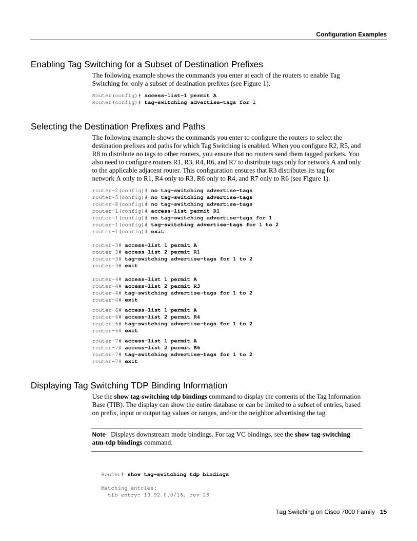
Displaying Tag Switching TDP Binding InformationUse theshow tag-switching tdp bindingscommand to display the contents of the Tag InformationBase (TIB). The display can show the entire database or can be limited to a subset of entries, basedon prefix, input or output tag values or ranges, and/or the neighbor advertising the tag.
Note Displays downstream mode bindings. For tag VC bindings, see the show tag-switchingatm-tdp bindings command.
Router# show tag-switching tdp bindings
Matching entries: tib entry: 10.92.0.0/16, rev 28

Configuration Examples
16 Cisco IOS Release 11.1CT
local binding: tag: imp-null(1) remote binding: tsr: 172.27.32.29:0, tag: imp-null(1) tib entry: 10.102.0.0/16, rev 29 local binding: tag: 26 remote binding: tsr: 172.27.32.29:0, tag: 26 tib entry: 10.105.0.0/16, rev 30 local binding: tag: imp-null(1) remote binding: tsr: 172.27.32.29:0, tag: imp-null(1) tib entry: 10.205.0.0/16, rev 31 local binding: tag: imp-null(1) remote binding: tsr: 172.27.32.29:0, tag: imp-null(1) tib entry: 10.211.0.7/32, rev 32 local binding: tag: 27 remote binding: tsr: 172.27.32.29:0, tag: 28 tib entry: 10.220.0.7/32, rev 33 local binding: tag: 28 remote binding: tsr: 172.27.32.29:0, tag: 29 tib entry: 99.101.0.0/16, rev 35 local binding: tag: imp-null(1) remote binding: tsr: 172.27.32.29:0, tag: imp-null(1) tib entry: 100.101.0.0/16, rev 36 local binding: tag: 29 remote binding: tsr: 172.27.32.29:0, tag: imp-null(1) tib entry: 171.69.204.0/24, rev 37 local binding: tag: imp-null(1) remote binding: tsr: 172.27.32.29:0, tag: imp-null(1) tib entry: 172.27.32.0/22, rev 38 local binding: tag: imp-null(1) remote binding: tsr: 172.27.32.29:0, tag: imp-null(1) tib entry: 210.10.0.0/16, rev 39 local binding: tag: imp-null(1) tib entry: 210.10.0.8/32, rev 40 remote binding: tsr: 172.27.32.29:0, tag: 27
Displaying Tag Switching Forwarding Table InformationUse the show tag-switching forwarding-tablecommand to display the contents of the TagForwarding Information Base (TFIB). The TFIB lists the tags, output interface information, prefixor tunnel associated with the entry, and number of bytes received with each incoming tag. A requestcan show the entire TFIB or can be limited to a subset of entries. A request can also be restricted toselected entries in any of the following ways:
• Single entry associated with a given incoming tag
• Entries associated with a given output interface
• Entries associated with a given next hop
• Single entry associated with a given destination
• Single entry associated with a given tunnel having the current node as an intermediate hop
Router# show tag-switching forwarding-table
Local Outgoing Prefix Bytes tag Outgoing Next Hoptag tag or VC or Tunnel Id switched interface26 Untagged 10.253.0.0/16 0 Et4/0/0 172.27.32.428 1/33 10.15.0.0/16 0 AT0/0.1 point2point29 Pop tag 10.91.0.0/16 0 Hs5/0 point2point 1/36 10.91.0.0/16 0 AT0/0.1 point2point30 32 10.250.0.97/32 0 Et4/0/2 10.92.0.7 32 10.250.0.97/32 0 Hs5/0 point2point34 26 10.77.0.0/24 0 Et4/0/2 10.92.0.7
Configuration Examples
Tag Switching on Cisco 7000 Family 17
26 10.77.0.0/24 0 Hs5/0 point2point35 Untagged [T] 10.100.100.101/32 0 Tu301 point2point36 Pop tag 168.1.0.0/16 0 Hs5/0 point2point 1/37 168.1.0.0/16 0 AT0/0.1 point2point
[T] Forwarding through a TSP tunnel. View additional tagging info with the 'detail' option
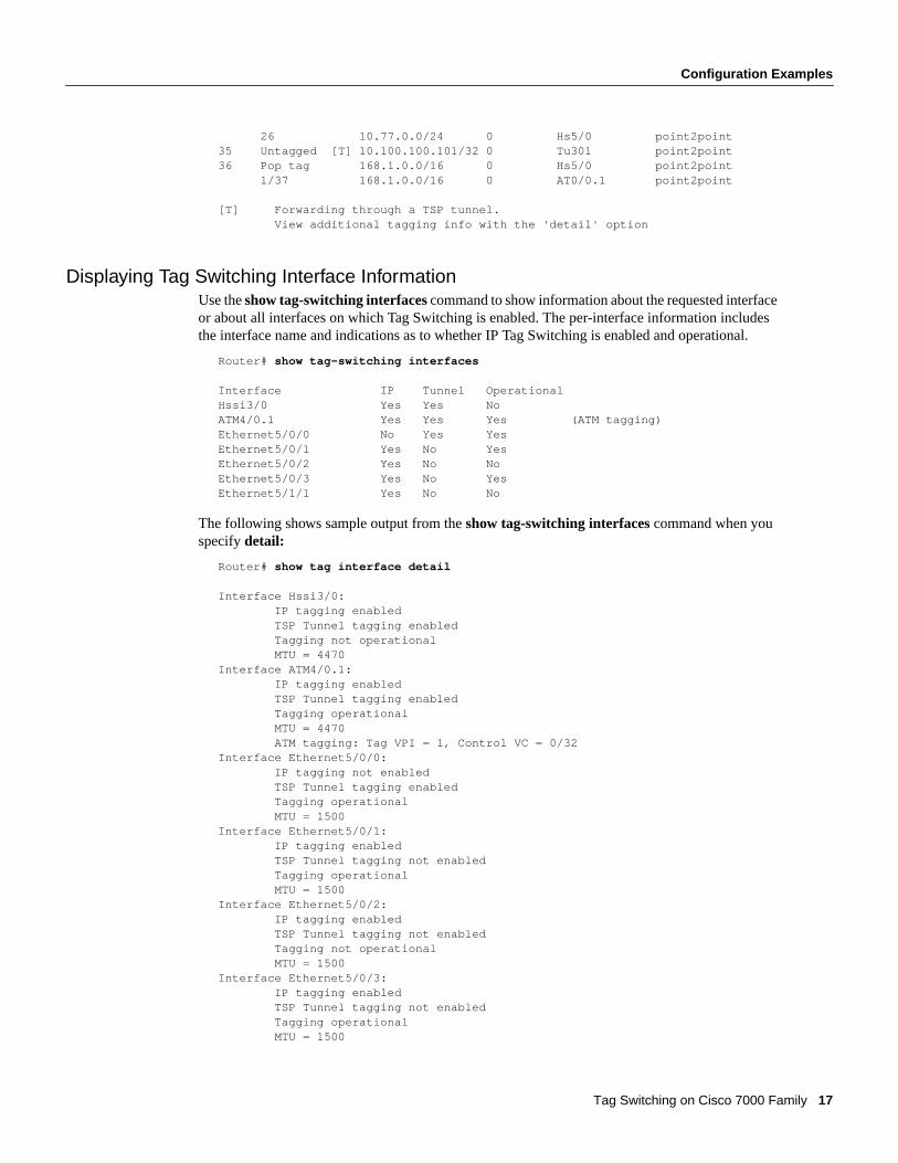
Displaying Tag Switching Interface InformationUse theshow tag-switching interfacescommand to show information about the requested interfaceor about all interfaces on which Tag Switching is enabled. The per-interface information includesthe interface name and indications as to whether IP Tag Switching is enabled and operational.
Router# show tag-switching interfaces
Interface IP Tunnel OperationalHssi3/0 Yes Yes NoATM4/0.1 Yes Yes Yes (ATM tagging)Ethernet5/0/0 No Yes YesEthernet5/0/1 Yes No YesEthernet5/0/2 Yes No NoEthernet5/0/3 Yes No YesEthernet5/1/1 Yes No No
The following shows sample output from theshow tag-switching interfacescommand when youspecifydetail:
Router# show tag interface detail
Interface Hssi3/0: IP tagging enabled TSP Tunnel tagging enabled Tagging not operational MTU = 4470Interface ATM4/0.1: IP tagging enabled TSP Tunnel tagging enabled Tagging operational MTU = 4470 ATM tagging: Tag VPI = 1, Control VC = 0/32Interface Ethernet5/0/0: IP tagging not enabled TSP Tunnel tagging enabled Tagging operational MTU = 1500Interface Ethernet5/0/1: IP tagging enabled TSP Tunnel tagging not enabled Tagging operational MTU = 1500Interface Ethernet5/0/2: IP tagging enabled TSP Tunnel tagging not enabled Tagging not operational MTU = 1500Interface Ethernet5/0/3: IP tagging enabled TSP Tunnel tagging not enabled Tagging operational MTU = 1500

Configuration Examples
18 Cisco IOS Release 11.1CT
Displaying Tag Switching TDP Neighbor InformationUse the show tag-switching tdp neighborscommand to display the status of Tag DistributionProtocol (TDP) sessions. The neighbor information branch can have information about all TDPneighbors or can be limited to the neighbor with a specific IP address or, TDP identifier, or to TDPneighbors known to be accessible over a specific interface.
Router# show tag-switching tdp neighbors
Peer TDP Ident: 10.220.0.7:1; Local TDP Ident 172.27.32.29:1 TCP connection: 10.220.0.7.711 - 172.27.32.29.11029 State: Oper; PIEs sent/rcvd: 17477/17487; Downstream on demandUp time: 01:03:00TDP discovery sources: ATM0/0.1Peer TDP Ident: 210.10.0.8:0; Local TDP Ident 172.27.32.29:0 TCP connection: 210.10.0.8.11004 - 172.27.32.29.711 State: Oper; PIEs sent/rcvd: 14656/14675; Downstream;Up time: 2d5h TDP discovery sources: Ethernet4/0/1 Ethernet4/0/2 POS6/0/0 Addresses bound to peer TDP Ident: 99.101.0.8 172.27.32.28 10.105.0.8 10.92.0.8 10.205.0.8 210.10.0.8
Enabling TSP Tunnel SignallingThe following example shows you how to configure support for tag-switched path (TSP) tunnelsignalling along a path and on each interface crossed by one or more tunnels:
Router(config)# ip cef distributedRouter(config)# tag-switching tsp-tunnelsRouter(config)# interface e0/1Router(config-if)# tag-switching tsp-tunnelsRouter(config-if)# interface e0/2Router(config-if)# tag-switching tsp-tunnelsRouter(config-if)# exit
Configuring a TSP TunnelThe following example shows you how to set the encapsulation of the tunnel to Tag Switching andhow to define hops in the path for the TSP.
Follow these steps to configure a two-hop tunnel, hop 0 being the headend router. For hops 1 and 2,you specify the IP addresses of the incoming interfaces for the tunnel. The tunnel interface numberis arbitrary, but must be less than 65,535.
Router(config)# interface tunnel 2003Router(config-if)# tunnel mode tag-switchingRouter(config-if)# tunnel tsp-hop 1 10.10.0.12Router(config-if)# tunnel tsp-hop 2 10.50.0.24 lasthopRouter(config-if)# exit
To shorten the previous path, you delete a hop by entering the following commands:
Router(config)# interface tunnel 2003Router(config-if)# no tunnel tsp-hop 2Router(config-if)# tunnel tsp-hop 1 10.10.0.12 lasthopRouter(config-if)# exit

Configuration Examples
Tag Switching on Cisco 7000 Family 19
Displaying the TSP Tunnel InformationUse the show tag-switching tsp tunnels command to display information about the configurationand status of selected tunnels.
Router# show tag-switching tsp-tunnels
Signalling Summary: TSP Tunnels Process: running RSVP Process: running Forwarding: enabled
TUNNEL ID DESTINATION STATUS CONNECTION10.106.0.6.2003 10.2.0.12 up up
Configuring a Traffic Engineering Filter and RouteThe following example shows you how to configure the traffic engineering routing process, a trafficengineering filter, and a traffic engineering route for that filter over a TSP-encapsulated tunnel.
Router(config)# router traffic-engineeringRouter(config-router)# traffic-engineering filter 5 egress 83.0.0.1 255.255.255.255Router(config-router)# traffic-engineering route 5 tunnel 5
Displaying Traffic Engineering Configuration InformationUse theshow ip traffic-engineering configurationcommand to display information about theconfigured traffic engineering filters and routes. The following is sample output from the show iptraffic-engineering configuration detailcommand.
Router# show ip traffic-engineering configuration detail
Traffic Engineering Configuration Filter 5: egress 44.0.0.0/8, local metric: ospf-0/1 Tunnel5 route installed interface up, route enabled, preference 1 loop check on, passing, remote metric: connected/0 Filter 6: egress 43.0.0.1/32, local metric: ospf-300/3 Tunnel7 route installed interface up, route enabled, preference 50 loop check on, passing, remote metric: ospf-300/2 Tunnel6 route not installed interface up, route enabled, preference 75 loop check on, passing, remote metric: connected/0
Command Reference
20 Cisco IOS Release 11.1CT
Command ReferenceThis section documents new or modified commands. All other commands used with this feature aredocumented in the Cisco IOS Release 11.1 command references.
This section includes commands supported for Tag Switching. There are no examples of commandoutput for the configuration commands, since they typically do not generate output.
All other commands used with this feature are documented in the Cisco IOS Release 11.1 commandreferences.
• router traffic-engineering
• show ip traffic-engineering
• show ip traffic-engineering configuration
• show ip traffic-engineering routes
• show tag-switching atm-tdp bindings
• show tag-switching atm-tdp capability
• show tag-switching atm-tdp summary
• show tag-switching forwarding-table
• show tag-switching interfaces
• show tag-switching tdp bindings
• show tag-switching tdp discovery
• show tag-switching tdp neighbors
• show tag-switching tdp parameters
• show tag-switching tsp-tunnels
• tag-switching advertise-tags
• tag-switching atm allocation-mode
• tag-switching atm control-vc
• tag-switching atm maxhops
• tag-switching atm vc-merge
• tag-switching atm vpi
• tag-switching ip (configuration)
• tag-switching ip (interface)
• tag-switching mtu
• tag-switching tag-range downstream
• tag-switching tdp discovery
• tag-switching tdp holdtime
• tag-switching tsp-tunnels (configuration)
• tag-switching tsp-tunnels (interface)
• traffic-engineering filter
• traffic-engineering route

Command Reference
Tag Switching on Cisco 7000 Family 21
• tunnel mode tag-switching
• tunnel tsp-hop

Command Reference
22 Cisco IOS Release 11.1CT
router traffic-engineeringTo configure the traffic engineering routing process, use therouter traffic-engineering globalconfiguration command. To turn off the traffic engineering routing process and delete any associatedconfiguration, use theno form of this command.
router traffic-engineeringno router traffic-engineering
Syntax DescriptionThis command has no arguments or keywords.
DefaultTraffic engineering process is disabled.
Command ModeGlobal configuration
ExampleIn the following example, configuration is provided for a traffic engineering routing process, a trafficengineering filter, and a traffic engineering route for that filter over a TSP tunnel.
router traffic-engineeringtraffic-engineering filter 5 egress 83.0.0.1 255.255.255.255traffic-engineering route 5 tunnel 5
Related Commandsshow ip traffic-engineeringtraffic-engineering filtertraffic-engineering route

Command Reference
Tag Switching on Cisco 7000 Family 23
show ip traffic-engineeringTo display information about the traffic engineering configuration and metric information associatedwith it, use the show ip traffic-engineeringcommand.
show ip traffic-engineering[metrics [detail]]
Syntax Description
Command ModePrivileged EXEC
Usage GuidelinesThe goal of the loop prevention algorithm is that traffic should not be sent down the tunnel if thereis a possibility that, after leaving the tunnel, steady state routing will route the traffic back to the headof the tunnel.
The approach of the loop prevention algorithm is to compare the Layer 3 routing distance to theegress from the tunnel tailend and tunnel headend. The loop check passes only if the tunnel tail iscloser to the egress than the tunnel head is.
The loop prevention algorithm allows you to use the tunnel for a route if one the following casesapplies:
• Given that the two ends of the tunnel are routing to the egress using the same dynamic protocolin the same area, the Layer 3 routing distance from the tailend to the egress is less than the Layer3 routing distance from the headend to the egress.
• The route to the egress is directly connected at the tunnel tailend router, but not at the tunnelheadend router.
• The egress is unreachable from the tunnel headend router, but is reachable from the tunnel tailendrouter.
The loop prevention algorithm prevents you from using the tunnel for a given egress in all othercases. In particular, when
• The routers at the ends of the tunnel get their route to the egress from different dynamic routingprotocols.
• The routing protocols at the two ends of the tunnel route to the egress through different areas.
• The two ends each use a static route to the egress.
• The tunnel headend router's route to the egress is a connected route.
• The egress is unreachable from the tunnel tailend router.
Devices request metrics via a TDP adjacency. The display output shows detailed metric information.
The metric information includes a metric type (shown asrouting_protocol/routing_protocol_subtype) and a metric value.
The routing protocol is as follows:
metrics Metric information associated with trafficengineering.
detail (Optional.) Display information in long form.

Command Reference
24 Cisco IOS Release 11.1CT
OSPFIS-ISEIGRPConnectedStaticOther (some other routing protocol)
The routing protocol subtype is specific to each routing protocol.
Sample DisplayThe following is sample output from theshow ip traffic-engineering metrics detailcommand:
Router# show ip traffic-engineering metrics detail
Metrics requested BY this device Prefix 43.0.0.1/32 TDP id 2.2.2.2:0, metric: connected/0 type request, flags metric-received, rev 6, refcnt 1 TDP id 4.4.4.4:0, metric: ospf-300/2 type request, flags metric-received, rev 7, refcnt 1 Prefix 44.0.0.0/8 TDP id 18.18.18.18:0, metric: connected/0 type request, flags metric-received, rev 1, refcnt 1Metrics requested FROM this device Prefix 36.0.0.0/8 TDP id 18.18.18.18:0, metric: connected/0 type advertise, flags none, rev 1, refcnt 1
Table 3 lists the fields displayed in the first three lines of this display.
Table 3 First Three Lines of Show IP Traffic-Engineering Field Descriptions
Field Description
Prefix Destination network and mask.
TDP id The TDP identifier of the TDP peer device atthe other end of the tunnel. The TDP peerdevice advertises these metrics to thisneighbor.
metric The routing protocol and metric within thatprotocol for the prefix in question.
type For metrics being requested by this device, thetype is either request or release. For metricsbeing requested from this device, the type isadvertise.
flags For metrics being requested by this devicemetric-received indicates that the other endhas responded with a metric value. For metricsbeing requested from this device,response-pending indicates that the metricvalue has not yet been sent to the requester.
Command Reference
Tag Switching on Cisco 7000 Family 25
Related Commandsrouter traffic-engineeringtraffic-engineering filtertraffic-engineering route
rev An internal identifier for the metric request oradvertisement. The rev number is assignedwhen the request/advertisement is created.The rev number is updated if the localinformation for the metric changes.
refcnt For a metric of type request, the number oftraffic engineering routes interested in thismetric value. Otherwise, refcnt is 1.

Command Reference
26 Cisco IOS Release 11.1CT
show ip traffic-engineering configurationTo display information about configured traffic engineering filters and routes, use the show iptraffic-engineering configuration command.
show ip traffic-engineering configuration[interface] [filter-number] [detail]
Syntax Description
Command ModePrivileged EXEC
Usage GuidelinesThe sample output can show all filters or can be limited by interface, filter number, or both.
Sample DisplayThe following is sample output from theshow ip traffic-engineering configuration detailcommand:
Router# show ip traffic-engineering configuration detail
Traffic Engineering Configuration Filter 5: egress 44.0.0.0/8, local metric: ospf-0/1 Tunnel5 route installed interface up, preference 1 loop check on, passing, remote metric: connected/0 Filter 6: egress 43.0.0.1/32, local metric: ospf-300/3 Tunnel7 route installed interface up, preference 50 loop check on, passing, remote metric: ospf-300/2 Tunnel6 route not installed interface up, preference 75 loop check on, passing, remote metric: connected/0
interface (Optional.) Displays traffic engineeringinformation for a specified interface.
filter-number (Optional.) A decimal value representing thenumber of the filter to display.
detail (Optional.) Display of command output inlong form.

Command Reference
Tag Switching on Cisco 7000 Family 27
Table 4 lists the fields displayed in the first four lines of this display.
Table 4 First Four Lines of Show IP Traffic-Engineering Configuration FieldDescriptions
Related Commandsshow ip traffic-engineering routes
Field Description
Filter The configured filter identifier for the trafficengineering route.
egress The prefix/mask configured with the filterlocal metric.
local metric The local TSR's routing protocol and metricvalue for the egress prefix/mask.
Tunnel5 The tunnel for the traffic engineering route.
route installed/not installed Indicates whether the route is installed in theforwarding tables (typically CEF and taginterface up/down).
interface Indicates whether the tunnel interface for thetraffic engineering route is up or down. Thetraffic engineering route is not installed if thetunnel interface is down.
preference The configured administrative preference forthe traffic engineering route.
loop check Indicates whether the loop check has beenconfigured on or off.
passing/failing If the loop check is configured on, indicateswhether the check is passing. The trafficengineering route is not installed if the loopcheck is configured on and is failing.
remote metric The routing protocol and the metric withinthat protocol for the prefix in question, as seenby the TSR advertising the metric. As part ofthe loop check, a comparison is made betweenthe remote metric and the local metric.

Command Reference
28 Cisco IOS Release 11.1CT
show ip traffic-engineering routesTo display information about the requested filters configured for traffic engineering, use theshow iptraffic-engineering routes command.
show ip traffic-engineering routes[filter-number] [detail]
Syntax Description
Command ModePrivileged EXEC
Usage GuidelinesRequests can be limited to a specific filter.
Sample DisplayThe following is sample output from theshow ip traffic-engineering routescommand:
Router# show ip traffic-engineering routes
Installed traffic engineering routes:Codes: T - traffic engineered routeT 43.0.0.1/32 (not override of routing table entry) is directly connected, 00:06:35, Tunnel7T 44.0.0.0/8 (override of routing table entry) is directly connected, 01:12:39, Tunnel5
Table 5 lists the significant fields in this display.
Table 5 Show IP Traffic-Engineering Routes Field Description
Related Commandsshow ip traffic-engineering configuration
filter-number (Optional.) A decimal value representing thenumber of the filter to display.
detail (Optional.) Display of command output inlong form.
Field Description
T Traffic engineering route.
43.0.0.1/32 (not override ofrouting table entry) is directlyconnected
Prefix/mask being routed. The routing tabledoes not contain an entry for this prefix/mask.
00:06:35 The time since the route was installed(hours:minutes:seconds).
Tunnel7 The TSP tunnel for the route.

Command Reference
Tag Switching on Cisco 7000 Family 29
show tag-switching atm-tdp bindingsTo display the requested entries from the ATM TDP tag binding database, use theshowtag-switching atm-tdp bindingscommand. The ATM TDP database contains TIB entries for tagVCs on TC-ATM interfaces.
show tag-switching atm-tdp bindings[network{ mask| length}][local-tag vpi vci][ remote-tagvpi vci] [neighbor interface]
Syntax Description
Command ModePrivileged EXEC
Usage GuidelinesThe display output can show entries from the entire database, or it can be limited to a subset ofentries based on prefix, VC tag value, and/or an assigning interface.
Sample DisplaysThe following is router sample output from theshow tag-switching atm-tdp bindingscommand:
Router# show tag-switching atm-tdp bindings
Destination: 10.16.0.16/32 Tailend Router ATM1/0.1 1/35 1/34 Active, VCD=2Destination: 10.24.0.0/24 Tailend Router ATM1/0.1 1/39 Active, VCD=3Destination: 10.15.0.15/32 Tailend Router ATM1/01 1/33 Active, VCD=4Destination: 10.23.0 0/24 Tailend Router ATM1/01 1/37 Active, VCD=5
network (Optional.) Destination network number.
mask Network mask in the form A.B.C.D(destination prefix).
length Mask length (1 to 32).
local-tagvpi vci (Optional.) Select tag VC value assigned bythis router.
remote-tagvpi vci (Optional.) Select tag values assigned by theother router.
neighbor interface (Optional.) Select tag values assigned byneighbor on a specified interface.

Command Reference
30 Cisco IOS Release 11.1CT
Table 6 lists the significant fields in this display.
Table 6 Show Tag-Switching ATM-TDP Bindings Field Descriptions
The following is ATM switch sample output from theshow tag-switching atm-tdp bindingscommand:
Switch# show tag-switching atm-tdp bindings
Destination: 6.6.6.6/32 Tailend Switch ATM0/0/3 1/34 Active -> Terminating Active Destination: 150.0.0.0/16 Tailend Switch ATM0/0/3 1/35 Active -> Terminating Active Destination: 4.4.4.4/32 Transit ATM0/0/3 1/33 Active -> ATM0/1/1 1/33 Active
Related Commandsshow tag-switching atm-tdp summary
Field Description
Destination: Destination (network/mask)
Tailend Router Types of VC. Options are
Tailend—VC that terminates at this router
Headend—VC that originates at this router
Transit—VC that passes through a switch
ATM1/0.1 Interface.
1/35 VPI/VCI.
Active TVC state:
Active—Set up and working.
Bindwait—Waiting for response.
Remote Resource Wait—Waiting for resources(VPI/VCI space) to be available on the downstreamdevice.
Parent Wait—Transit VC input side waiting foroutput side to become active.
VCD=2 Virtual circuit descriptor number.
Command Reference
Tag Switching on Cisco 7000 Family 31
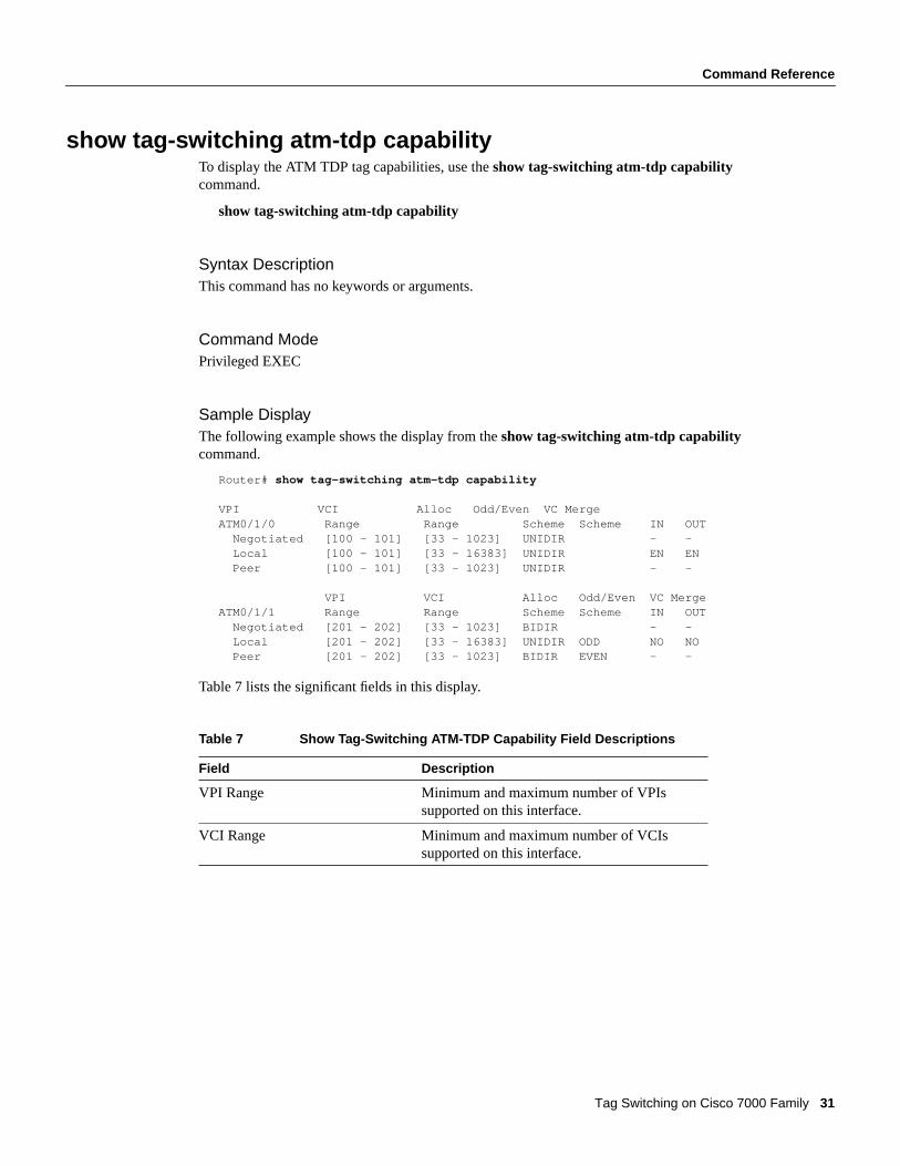
show tag-switching atm-tdp capabilityTo display the ATM TDP tag capabilities, use theshow tag-switching atm-tdp capabilitycommand.
show tag-switching atm-tdp capability
Syntax DescriptionThis command has no keywords or arguments.
Command ModePrivileged EXEC
Sample DisplayThe following example shows the display from theshow tag-switching atm-tdp capabilitycommand.
Router# show tag-switching atm-tdp capability
VPI VCI Alloc Odd/Even VC MergeATM0/1/0 Range Range Scheme Scheme IN OUT Negotiated [100 - 101] [33 - 1023] UNIDIR - - Local [100 - 101] [33 - 16383] UNIDIR EN EN Peer [100 - 101] [33 - 1023] UNIDIR - -
VPI VCI Alloc Odd/Even VC MergeATM0/1/1 Range Range Scheme Scheme IN OUT Negotiated [201 - 202] [33 - 1023] BIDIR - - Local [201 - 202] [33 - 16383] UNIDIR ODD NO NO Peer [201 - 202] [33 - 1023] BIDIR EVEN - -
Table 7 lists the significant fields in this display.
Table 7 Show Tag-Switching ATM-TDP Capability Field Descriptions
Field Description
VPI Range Minimum and maximum number of VPIssupported on this interface.
VCI Range Minimum and maximum number of VCIssupported on this interface.
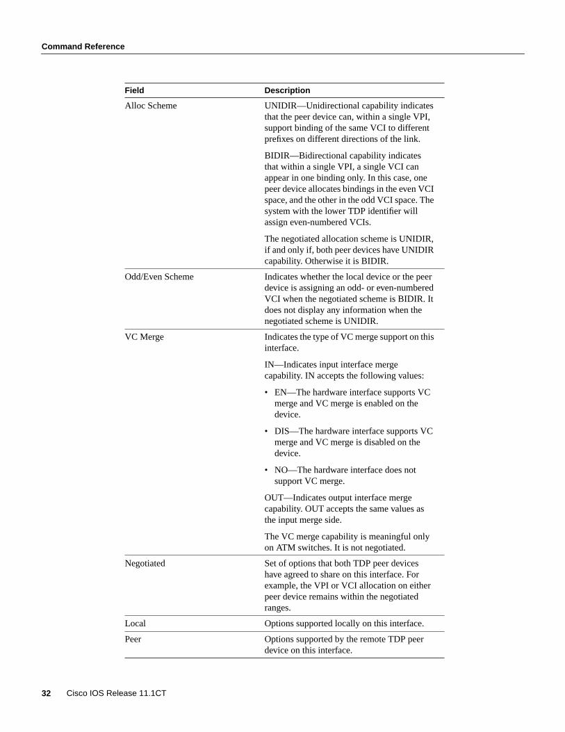
Command Reference
32 Cisco IOS Release 11.1CT
Alloc Scheme UNIDIR—Unidirectional capability indicatesthat the peer device can, within a single VPI,support binding of the same VCI to differentprefixes on different directions of the link.
BIDIR—Bidirectional capability indicatesthat within a single VPI, a single VCI canappear in one binding only. In this case, onepeer device allocates bindings in the even VCIspace, and the other in the odd VCI space. Thesystem with the lower TDP identifier willassign even-numbered VCIs.
The negotiated allocation scheme is UNIDIR,if and only if, both peer devices have UNIDIRcapability. Otherwise it is BIDIR.
Odd/Even Scheme Indicates whether the local device or the peerdevice is assigning an odd- or even-numberedVCI when the negotiated scheme is BIDIR. Itdoes not display any information when thenegotiated scheme is UNIDIR.
VC Merge Indicates the type of VC merge support on thisinterface.
IN—Indicates input interface mergecapability. IN accepts the following values:
• EN—The hardware interface supports VCmerge and VC merge is enabled on thedevice.
• DIS—The hardware interface supports VCmerge and VC merge is disabled on thedevice.
• NO—The hardware interface does notsupport VC merge.
OUT—Indicates output interface mergecapability. OUT accepts the same values asthe input merge side.
The VC merge capability is meaningful onlyon ATM switches. It is not negotiated.
Negotiated Set of options that both TDP peer deviceshave agreed to share on this interface. Forexample, the VPI or VCI allocation on eitherpeer device remains within the negotiatedranges.
Local Options supported locally on this interface.
Peer Options supported by the remote TDP peerdevice on this interface.
Field Description

Command Reference
Tag Switching on Cisco 7000 Family 33
Related Commandtag-switching atm control-vctag-switching atm vc-mergetag-switching atm vpi

Command Reference
34 Cisco IOS Release 11.1CT
show tag-switching atm-tdp summaryTo display summary information on ATM tag bindings, use the show tag-switching atm-tdpsummary command.
show tag-switching atm-tdp summary
Syntax DescriptionThis command has no arguments or keywords.
Command ModePrivileged EXEC
Sample DisplayThe following is sample output from theshow tag-switching atm-tdp summarycommand:
Router# show tag-switching atm-tdp summary
Total number of destinations: 788
TC-ATM bindings summaryinterface total active bindwait local remote otherATM0/0/0 594 592 1 296 298 1ATM0/0/1 590 589 0 294 296 1ATM0/0/2 1179 1178 0 591 588 1ATM0/0/3 1177 1176 0 592 585 1ATM0/1/0 1182 1178 4 590 588 0Waiting for bind on ATM0/0/0 10.21.0.0/24
Table 8 lists the significant fields in this display.
Table 8 Show Tag-Switching ATM-TDP Summary Field Descriptions
Field Description
Total number of destinations The number of known destination addressprefixes.
interface The name of an interface with associatedATM tag bindings.
total The total number of ATM tags on thisinterface.
active The number of ATM tags in an “active” statethat are ready to use for data transfer.
bindwait The number of bindings that are waiting for atag assignment from the neighbor TSR.
local The number of ATM tags assigned by thisTSR on this interface.
remote The number of ATM tags assigned by theneighbor TSR on this interface.

Command Reference
Tag Switching on Cisco 7000 Family 35
Related Commandsshow tag-switching atm-tdp bindings
other The number of ATM tags in a state other than“active” or “bindwait.”
Waiting for bind on ATM0/0/0 A list of the destination address prefixes (on aparticular interface) that are waiting for ATMtag assignment from the neighbor TSR.
Field Description
Command Reference
36 Cisco IOS Release 11.1CT
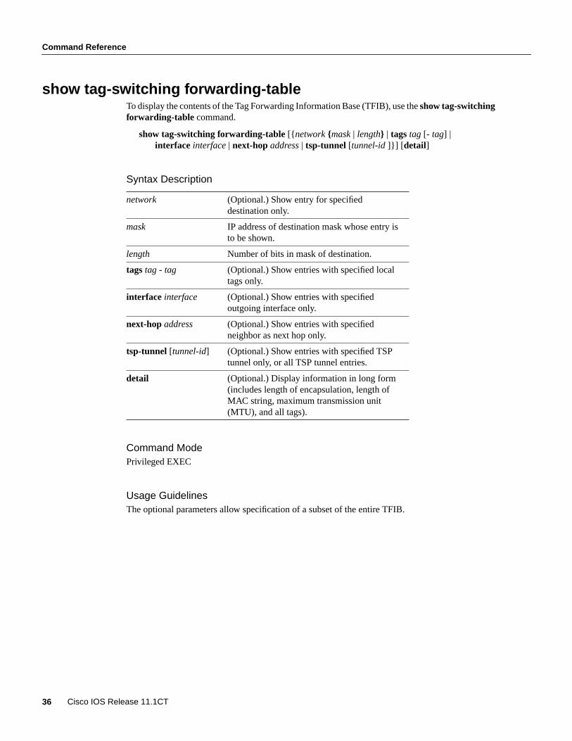
show tag-switching forwarding-tableTo display the contents of the Tag Forwarding Information Base (TFIB), use theshow tag-switchingforwarding-table command.
show tag-switching forwarding-table[{ network {mask| length} | tagstag [- tag] |interface interface| next-hopaddress| tsp-tunnel [tunnel-id ]}] [ detail]
Syntax Description
Command ModePrivileged EXEC
Usage GuidelinesThe optional parameters allow specification of a subset of the entire TFIB.
network (Optional.) Show entry for specifieddestination only.
mask IP address of destination mask whose entry isto be shown.
length Number of bits in mask of destination.
tagstag - tag (Optional.) Show entries with specified localtags only.
interface interface (Optional.) Show entries with specifiedoutgoing interface only.
next-hopaddress (Optional.) Show entries with specifiedneighbor as next hop only.
tsp-tunnel [tunnel-id] (Optional.) Show entries with specified TSPtunnel only, or all TSP tunnel entries.
detail (Optional.) Display information in long form(includes length of encapsulation, length ofMAC string, maximum transmission unit(MTU), and all tags).

Command Reference
Tag Switching on Cisco 7000 Family 37
Sample DisplaysThe following is sample output from theshow tag-switching forwarding-tablecommand:
Router# show tag-switching forwarding-table
Local Outgoing Prefix Bytes tag Outgoing Next Hoptag tag or VC or Tunnel Id switched interface26 Untagged 10.253.0.0/16 0 Et4/0/0 172.27.32.428 1/33 10.15.0.0/16 0 AT0/0.1 point2point29 Pop tag 10.91.0.0/16 0 Hs5/0 point2point 1/36 10.91.0.0/16 0 AT0/0.1 point2point30 32 10.250.0.97/32 0 Et4/0/2 10.92.0.7 32 10.250.0.97/32 0 Hs5/0 point2point34 26 10.77.0.0/24 0 Et4/0/2 10.92.0.7 26 10.77.0.0/24 0 Hs5/0 point2point35 Untagged [T] 10.100.100.101/32 0 Tu301 point2point36 Pop tag 168.1.0.0/16 0 Hs5/0 point2point 1/37 168.1.0.0/16 0 AT0/0.1 point2point
[T] Forwarding through a TSP tunnel. View additional tagging info with the 'detail' option
The following is sample output from theshow tag-switching forwarding-tablecommand whenyou specify detail:
Router# show tag-switching forwarding-table detail
Local Outgoing Prefix Bytes tag Outgoing NextHoptag tag or VC or Tunnel Id switched interface26 Untagged 10.253.0.0/16 0 Et4/0/0 172.27.32.4 MAC/Encaps=0/0, MTU=1504, Tag Stack{}28 1/33 10.15.0.0/16 0 AT0/0.1 point2point MAC/Encaps=4/8, MTU=4470, Tag Stack{1/33(vcd=2)} 00020900 0000200029 Pop tag 10.91.0.0/16 0 Hs5/0 point2point MAC/Encaps=4/4, MTU=4474, Tag Stack{} FF030081 1/36 10.91.0.0/16 0 AT0/0.1 point2point MAC/Encaps=4/8, MTU=4470, Tag Stack{1/36(vcd=3)} 00030900 0000300030 32 10.250.0.97/32 0 Et4/0/2 10.92.0.7 MAC/Encaps=14/18, MTU=1500, Tag Stack{32} 006009859F2A00E0F7E984828847 00020000 32 10.250.0.97/32 0 Hs5/0 point2point MAC/Encaps=4/8, MTU=4470, Tag Stack{32} FF030081 0002000034 26 10.77.0.0/24 0 Et4/0/2 10.92.0.7 MAC/Encaps=14/18, MTU=1500, Tag Stack{26} 006009859F2A00E0F7E984828847 0001A000 26 10.77.0.0/24 0 Hs5/0 point2point MAC/Encaps=4/8, MTU=4470, Tag Stack{26} FF030081 0001A00035 Untagged 10.100.100.101/32 0 Tu301 point2point MAC/Encaps=0/0, MTU=1504, Tag Stack{}, via Et4/0/236 Pop tag 168.1.0.0/16 0 Hs5/0 point2point MAC/Encaps=4/4, MTU=4474, Tag Stack{} FF030081 1/37 168.1.0.0/16 0 AT0/0.1 point2point MAC/Encaps=4/8, MTU=4470, Tag Stack{1/37(vcd=4)} 00040900 00004000
Table 9 lists the significant fields in this display.
Command Reference
38 Cisco IOS Release 11.1CT
Table 9 Show Tag-Switching Forwarding-Table Field Descriptions
Field Description
Local tag Tag assigned by this router.
Outgoing tag or VC Tag assigned by next hop, or VPI/VCI used toget to next hop. Some of the entries you canhave in this column are
• [T] means forwarding through a TSPtunnel.
• “Untagged” means there is no tag for thedestination from the next hop, or TagSwitching is not enabled on the outgoinginterface.
• “Pop tag” means the next hop advertised animplicit NULL tag for the destination, andthis router popped the top tag.
Prefix or Tunnel Id Address or tunnel to which packets with thistag are going.
Bytes tag switched Number of bytes switched with this incomingtag.
Outgoing interface Interface through which packets with this tagare sent.
NextHop IP address of neighbor that assigned theoutgoing tag.
Mac/Encaps Length in bytes of Layer 2 header, and lengthin bytes of packet encapsulation, includingLayer 2 header and tag header.
MTU Maximum transmission unit (MTU) of taggedpacket.
Tag Stack All the outgoing tags. If the outgoing interfaceis TC-ATM, the VCD is also shown.
00020900 00002000 The actual encapsulation in hexadecimalform. There is a space shown between Layer 2and tag header.

Command Reference
Tag Switching on Cisco 7000 Family 39
show tag-switching interfacesTo display information about one or more interfaces that have Tag Switching enabled, use theshowtag-switching interfacescommand.
show tag-switching interfaces[interface][detail]
Syntax Description
Command ModeEXEC
Usage GuidelinesYou can show information about the requested interface or about all interfaces on which TagSwitching is enabled.
Sample DisplayThe following is sample output from theshow tag-switching interfacescommand:
Router# show tag-switching interfaces
Interface IP Tunnel OperationalHssi3/0 Yes Yes NoATM4/0.1 Yes Yes Yes (ATM tagging)Ethernet5/0/0 No Yes YesEthernet5/0/1 Yes No YesEthernet5/0/2 Yes No NoEthernet5/0/3 Yes No YesEthernet5/1/1 Yes No No
Note If the interface uses TC-ATM procedures, the line in the display output is marked (ATM
tagging ).
interface (Optional.) The interface about which todisplay Tag Switching information.
detail (Optional.) Display information in long form.

Command Reference
40 Cisco IOS Release 11.1CT
Table 10 lists the significant fields in this display.
Table 10 Show Tag-Switching Interfaces Command Field Descriptions
The following is sample output from theshow tag-switching interfacescommand when youspecifydetail:
Router# show tag-switching interface Ethernet2/0/1 detail
Interface Hssi3/0: IP tagging enabled TSP Tunnel tagging enabled Tagging not operational MTU = 4470Interface ATM4/0.1: IP tagging enabled TSP Tunnel tagging enabled Tagging operational MTU = 4470 ATM tagging: Tag VPI = 1, Control VC = 0/32Interface Ethernet5/0/0: IP tagging not enabled TSP Tunnel tagging enabled Tagging operational MTU = 1500Interface Ethernet5/0/1: IP tagging enabled TSP Tunnel tagging not enabled Tagging operational MTU = 1500Interface Ethernet5/0/2: IP tagging enabled TSP Tunnel tagging not enabled Tagging not operational MTU = 1500Interface Ethernet5/0/3: IP tagging enabled TSP Tunnel tagging not enabled Tagging operational MTU = 1500
Related Commandstag-switching tsp-tunnelstag-switching ip
Field Description
Interface Interface name.
IP “Yes” if IP tagging has been enabled on thisinterface.
Tunnel “Yes” if TSP tunnel tagging has been enabledon this interface.
Operational Operational state. “Yes” if packets are beingtagged.
MTU Maximum number of data bytes per taggedpacket that will be transmitted.

Command Reference
Tag Switching on Cisco 7000 Family 41
show tag-switching tdp bindingsTo display the contents of the tag information base (TIB), use theshow tag-switching tdp bindingscommand:
show tag-switching tdp bindings[network {mask | length} [ longer-prefixes]][local-tag tag [- tag]} [ remote-tag tag [- tag] [neighbor address] [ local]
Syntax Description
Command ModePrivileged EXEC
Usage GuidelinesA request can specify that the entire database be shown, or it or can be limited to a subset of entries.A request to show a subset of entries can be based on the prefix, on input or output tag values or onranges, and/or the neighbor advertising the tag.
Sample DisplaysThe following is sample output from theshow tag-switching tdp bindingscommand. This form ofthe command causes the contents of the entire TIB to be displayed.
Router# show tag-switching tdp bindings
Matching entries: tib entry: 10.92.0.0/16, rev 28 local binding: tag: imp-null(1) remote binding: tsr: 172.27.32.29:0, tag: imp-null(1) tib entry: 10.102.0.0/16, rev 29 local binding: tag: 26 remote binding: tsr: 172.27.32.29:0, tag: 26 tib entry: 10.105.0.0/16, rev 30 local binding: tag: imp-null(1) remote binding: tsr: 172.27.32.29:0, tag: imp-null(1) tib entry: 10.205.0.0/16, rev 31
network (Optional.) Destination network number.
mask Network mask written as A.B.C.D.
length Mask length (1 to 32 characters).
longer-prefixes (Optional.) Select any prefix that matchesmask with length# to 32.
local-tagtag - tag (Optional.) Display entries matching local tagvalues by this router. Use the - tag option toindicate tag range.
remote-tagtag - tag (Optional.) Display entries matching tagvalues assigned by a neighbor router. Use the- tag option to indicate tag range.
neighbor address (Optional.) Display tag bindings assigned byselected neighbor.
local (Optional.) Display local tag bindings.

Command Reference
42 Cisco IOS Release 11.1CT
local binding: tag: imp-null(1) remote binding: tsr: 172.27.32.29:0, tag: imp-null(1) tib entry: 10.211.0.7/32, rev 32 local binding: tag: 27 remote binding: tsr: 172.27.32.29:0, tag: 28 tib entry: 10.220.0.7/32, rev 33 local binding: tag: 28 remote binding: tsr: 172.27.32.29:0, tag: 29 tib entry: 99.101.0.0/16, rev 35 local binding: tag: imp-null(1) remote binding: tsr: 172.27.32.29:0, tag: imp-null(1) tib entry: 100.101.0.0/16, rev 36 local binding: tag: 29 remote binding: tsr: 172.27.32.29:0, tag: imp-null(1) tib entry: 171.69.204.0/24, rev 37 local binding: tag: imp-null(1) remote binding: tsr: 172.27.32.29:0, tag: imp-null(1) tib entry: 172.27.32.0/22, rev 38 local binding: tag: imp-null(1) remote binding: tsr: 172.27.32.29:0, tag: imp-null(1) tib entry: 210.10.0.0/16, rev 39 local binding: tag: imp-null(1) tib entry: 210.10.0.8/32, rev 40 remote binding: tsr: 172.27.32.29:0, tag: 27
The following is sample output from the show tag tdp bindings 10.0.0.0 8 longer-prefixesneighbor 172.27.32.29variant of the command; it displays tags learned from TSR 172.27.32.29 fornetwork 10.0.0.0 and any of its subnets. The use of theneighbor option suppresses the output oflocal tags and tags learned from other neighbors.
Router# show tag tdp bindings 10.0.0.0 8 longer-prefixes neighbor 172.27.32.29
tib entry: 10.92.0.0/16, rev 28 remote binding: tsr: 172.27.32.29:0, tag: imp-null(1) tib entry: 10.102.0.0/16, rev 29 remote binding: tsr: 172.27.32.29:0, tag: 26 tib entry: 10.105.0.0/16, rev 30 remote binding: tsr: 172.27.32.29:0, tag: imp-null(1) tib entry: 10.205.0.0/16, rev 31 remote binding: tsr: 172.27.32.29:0, tag: imp-null(1) tib entry: 10.211.0.7/32, rev 32 remote binding: tsr: 172.27.32.29:0, tag: 28 tib entry: 10.220.0.7/32, rev 33 remote binding: tsr: 172.27.32.29:0, tag: 29
Command Reference
Tag Switching on Cisco 7000 Family 43
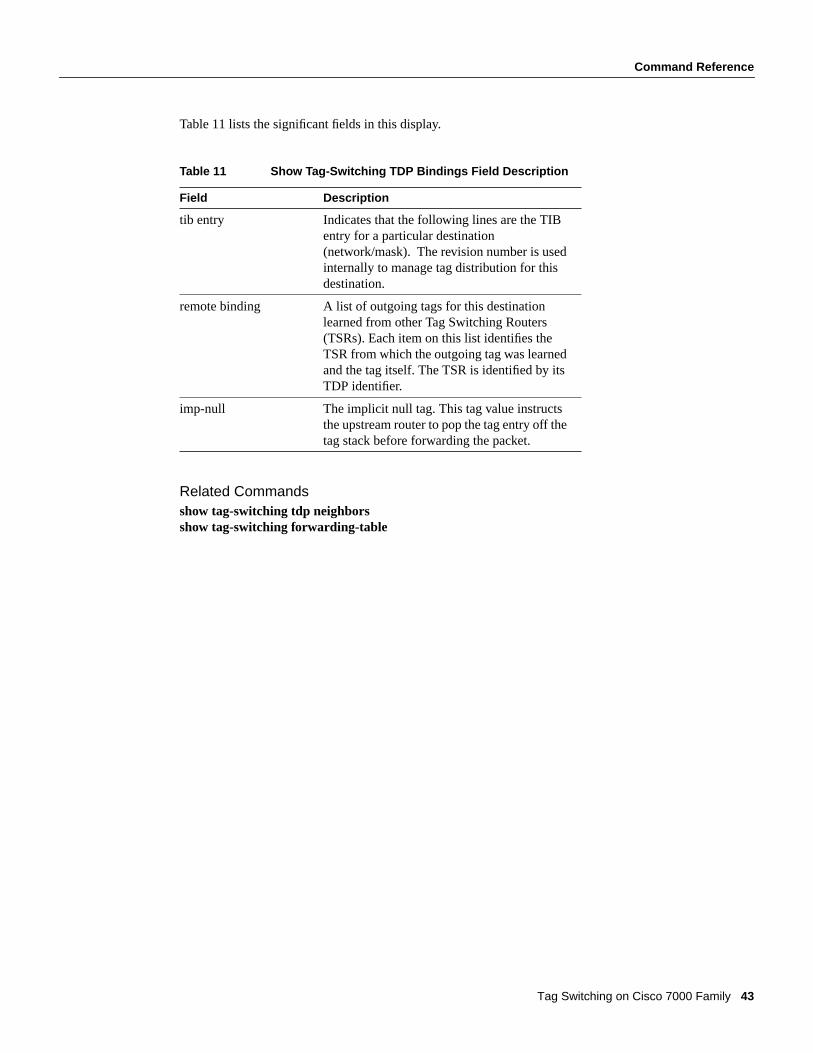
Table 11 lists the significant fields in this display.
Table 11 Show Tag-Switching TDP Bindings Field Description
Related Commandsshow tag-switching tdp neighborsshow tag-switching forwarding-table
Field Description
tib entry Indicates that the following lines are the TIBentry for a particular destination(network/mask). The revision number is usedinternally to manage tag distribution for thisdestination.
remote binding A list of outgoing tags for this destinationlearned from other Tag Switching Routers(TSRs). Each item on this list identifies theTSR from which the outgoing tag was learnedand the tag itself. The TSR is identified by itsTDP identifier.
imp-null The implicit null tag. This tag value instructsthe upstream router to pop the tag entry off thetag stack before forwarding the packet.

Command Reference
44 Cisco IOS Release 11.1CT
show tag-switching tdp discoveryTo display the status of the TDP discovery process, use theshow tag-switching tdp discoverycommand. Status means a list of interfaces over which TDP discovery is running.
show tag-switching tdp discovery
Syntax DescriptionThis command has no arguments or keywords.
Command ModePrivileged EXEC
Sample DisplayThe following is sample output from theshow tag-switching tdp discovery command.
Router# show tag-switching tdp discovery
Local TDP Identifier: 172.27.32.29:0TDP Discovery Sources: Interfaces:
ATM0/0.1: xmit/recvATM0/0.1: xmit/recEthernet4/0/1: xmit/recvEthernet4/0/2: xmit/recvPOS6/0/0: xmit/recv
Table 12 lists the significant fields in this display.
Table 12 Show Tag-Switching TDP Discovery Field Descriptions
Related Commandsshow tag-switching tdp neighbors
Field Description
Local TDP Identifier The TDP identifier for the local router. A TDPidentifier is a 6-byte quantity displayed as an IPaddress:number.
The Cisco convention is to use a router ID for the first 4bytes of the TDP identifier, and integers starting with 0for the final two bytes of the IP address:number.
Interfaces Lists the interfaces engaging in TDP discovery activity.xmit indicates that the interface is transmitting TDPdiscovery hello packets; recv indicates that theinterface is receiving TDP discovery hello packets.

Command Reference
Tag Switching on Cisco 7000 Family 45
show tag-switching tdp neighborsTo display the status of Tag Distribution Protocol (TDP) sessions, enter theshow tag-switching tdpneighbor command:
show tag-switching tdp neighbors{[ address | interface] [detail]}
Syntax Description
Command ModePrivileged EXEC
Usage GuidelinesThe neighbor information branch can give information about all TDP neighbors, or it can be limitedto
• The neighbor with a specific IP address
• TDP neighbors known to be accessible over a specific interface
Sample DisplayThe following is sample output from theshow tag-switching tdp neighborscommand:
Router# show tag-switching tdp neighbors
Peer TDP Ident: 10.220.0.7:1; Local TDP Ident 172.27.32.29:1 TCP connection: 10.220.0.7.711 - 172.27.32.29.11029 State: Oper; PIEs sent/rcvd: 17477/17487; Downstream on demandUp time: 01:03:00TDP discovery sources: ATM0/0.1Peer TDP Ident: 210.10.0.8:0; Local TDP Ident 172.27.32.29:0 TCP connection: 210.10.0.8.11004 - 172.27.32.29.711 State: Oper; PIEs sent/rcvd: 14656/14675; DownstreamUp time: 2d5h TDP discovery sources: Ethernet4/0/1 Ethernet4/0/2 POS6/0/0 Addresses bound to peer TDP Ident: 99.101.0.8 172.27.32.28 10.105.0.8 10.92.0.8 10.205.0.8 210.10.0.8
Table 13 lists the significant fields in this display.
address (Optional.) The neighbor with this IP address.
interface (Optional.) TDP neighbors accessible overthis interface.
detail (Optional.) Display information in long form.

Command Reference
46 Cisco IOS Release 11.1CT
Table 13 Show Tag-Switching TDP Neighbors Field Descriptions
Related Commandsshow tag-switching tdp discovery
Field Description
Peer TDP Ident The TDP identifier of the neighbor (peer device) forthis session.
Local TDP Ident The TDP identifier for the local TSR for this session.
TCP connection The TCP connection used to support the TDP session.The format for displaying the TCP connection is
peer IP address.peer portlocal IP address.local port
State The state of the TDP session. Generally this is Oper(operational), but transient is another possible state.
PIEs sent/rcvd The number of TDP protocol information elements(PIEs) sent to and received from the session peerdevice. The count includes the transmission andreceipt of periodic keep alive PIEs, which are requiredfor maintenance of the TDP session.
Downstream Indicates that the downstream method of tagdistribution is being used for this TDP session. Whenthe downstream method is used, a TSR advertises all ofits locally assigned (incoming) tags to its TDP peerdevice (subject to any configured access listrestrictions).
Downstream on demand Indicates that the downstream on demand method oftag distribution is being used for this TDP session.When the downstream on demand method is used, aTSR advertises its locally assigned (incoming) tags toits TDP peer device only when the peer device asks forthem.
Up time The length of time the TDP session has existed.
TDP discovery sources The source(s) of TDP discovery activity that led to theestablishment of this TDP session.
Addresses bound to peerTDP Ident
The known interface addresses of the TDP session peerdevice. These are addresses that may appear as "nexthop" addresses in the local routing table. They are usedto maintain the Tag Forwarding Information Base(TFIB).

Command Reference
Tag Switching on Cisco 7000 Family 47
show tag-switching tdp parametersTo display available TDP parameters, use theshow tag-switching tdp parameterscommand:
show tag-switching tdp parameters
Syntax DescriptionThis command has no keywords or arguments.
Command ModePrivileged EXEC
Sample DisplayThe following example shows the display from theshow tag-switching tdp parameterscommand:
Router# show tag-switching tdp parameters
Protocol version: 1 Downstream tag pool: min tag: 10; max_tag: 10000; reserved tags: 16 Session hold time: 15 sec; keep alive interval: 5 sec Discovery hello: holdtime: 15 sec; interval: 5 sec Discovery directed hello: holdtime: 15 sec; interval: 5 sec Accepting directed hellos
Table 14 lists the significant fields in this display.
Table 14 Show Tag-Switching TDP Parameters Command Field Descriptions
Field Description
Protocol version Indicates the version of the Tag Distribution Protocol (TDP)running on the platform.
Downstream tag pool Describes the range of tags available for the platform toassign for Tag Switching. The tags available run from thesmallest tag value (min tag) to the largest tag value (max tag),with a modest number of tags at the low end of the range(reserved tags) reserved for diagnostic purposes.
Session hold time Indicates the time to maintain a TDP session with a TDP peerdevice without receiving TDP traffic or a TDP keep alivefrom the peer device.
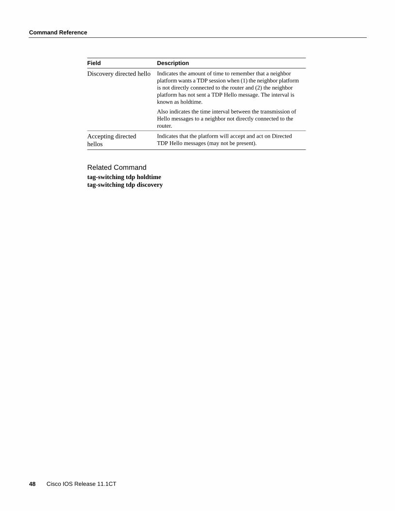
keep alive interval Indicates the interval of time between consecutivetransmission TDP keep alive messages to a TDP peer device.
Discovery hello Indicates the amount of time to remember that a neighborplatform wants a TDP session without receiving a TDP Hellofrom the neighbor (holdtime), and the time interval betweentransmitting TDP Hello messages to neighbors (interval).
Command Reference
48 Cisco IOS Release 11.1CT
Related Commandtag-switching tdp holdtimetag-switching tdp discovery
Discovery directed hello Indicates the amount of time to remember that a neighborplatform wants a TDP session when (1) the neighbor platformis not directly connected to the router and (2) the neighborplatform has not sent a TDP Hello message. The interval isknown as holdtime.
Also indicates the time interval between the transmission ofHello messages to a neighbor not directly connected to therouter.
Accepting directedhellos
Indicates that the platform will accept and act on DirectedTDP Hello messages (may not be present).
Field Description
Command Reference
Tag Switching on Cisco 7000 Family 49
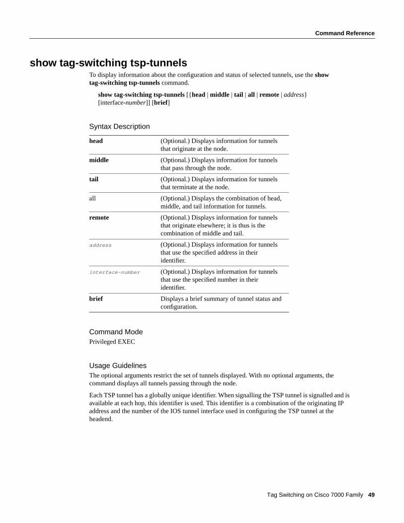
show tag-switching tsp-tunnelsTo display information about the configuration and status of selected tunnels, use the showtag-switching tsp-tunnels command.
show tag-switching tsp-tunnels[{ head | middle | tail | all | remote | address}[interface-number]] [brief ]
Syntax Description
Command ModePrivileged EXEC
Usage GuidelinesThe optional arguments restrict the set of tunnels displayed. With no optional arguments, thecommand displays all tunnels passing through the node.
Each TSP tunnel has a globally unique identifier. When signalling the TSP tunnel is signalled and isavailable at each hop, this identifier is used. This identifier is a combination of the originating IPaddress and the number of the IOS tunnel interface used in configuring the TSP tunnel at theheadend.
head (Optional.) Displays information for tunnelsthat originate at the node.
middle (Optional.) Displays information for tunnelsthat pass through the node.
tail (Optional.) Displays information for tunnelsthat terminate at the node.
all (Optional.) Displays the combination of head,middle, and tail information for tunnels.
remote (Optional.) Displays information for tunnelsthat originate elsewhere; it is thus is thecombination of middle and tail.
address (Optional.) Displays information for tunnelsthat use the specified address in theiridentifier.
interface-number (Optional.) Displays information for tunnelsthat use the specified number in theiridentifier.
brief Displays a brief summary of tunnel status andconfiguration.

Command Reference
50 Cisco IOS Release 11.1CT
Sample DisplayThe following is sample output from the show tag-switching tsp-tunnelscommand:
Signalling Summary: TSP Tunnels Process: running RSVP Process: running Forwarding: enabledTUNNEL ID DESTINATION STATUS CONNECTION10.106.0.6 0 10.2.0.12 up up
Table 15 lists the significant fields in this display.
Table 15 Show Tag-Switching TSP-Tunnels Field Descriptions
Related Commandstag-switching tsp-tunnelstunnel mode tag-switching
Field Description
Signalling Summary The status of the signalling and forwarding mechanismthat is required in order for TSP tunnels to be signalledthrough the router.
TSP Tunnels Process The status of the TSP tunnel signalling process. Thisprocess interacts with the signalling protocol to managesignalled tunnels and monitors the state of establishedtunnels.
RSVP Process The status of the RSVP process. You use the RSVPprotocol to signal tunnels.
Forwarding The status of the forwarding mechanism used to switchdata through local TSP tunnel segments.
TUNNEL ID The identity of the tunnel being summarized as shownin the previous display output. The tunnel ID includesan IP address part and a number part, and is uniquewithin the entire network.
DESTINATION The destination of the TSP tunnel being summarized asshown in the previous display output—the IP addressof the tunnel tail.
STATUS The configuration status of the tunnel. At the head, thisis an indication whether or not the tunnel has beencompletely configured. It also refers to the status of theassociated software and hardware interfaces.
CONNECTION The connection status of the tunnel. This is anindication whether or not the localsignalling/configuration information shows that thetunnel is up. Typically the tunnel becomes “up” at thetail hop first, and then at the second to the last hop, andso forth until signalling brings it up at the first hop.

Command Reference
Tag Switching on Cisco 7000 Family 51
tag-switching advertise-tagsTo control the distribution of locally assigned (incoming) tags via the Tag Distribution Protocol(TDP), use thetag-switching advertise-tags command. To disable tag advertisement, use thenoform of this command.
tag-switching advertise-tags[for access-list-number[to access-list-number]no tag-switching advertise-tags[for access-list-number[to access-list-number]
Syntax Description
DefaultAdvertise all to all is the default.
Command ModeGlobal configuration
Usage GuidelinesTo enable the distribution of all locally assigned tags to all TDP neighbors, use the tag-switchingadvertise-tagscommand
You can enter multipletag-switching advertise-tags commands. Taken together, they determinehow local tags are advertised.
Note This command has no effect for a TC-ATM interface. The effect is always as if thetag-switching advertise-tags command had been executed.
for access-list-number Specifies which destinations should have theirtags advertised.
to access-list-number Specifies which TSR neighbors should receivetag advertisements.
A TSR is identified by the router ID that is thefirst 4 bytes of its 6-byte TDP identifier.
Command Reference
52 Cisco IOS Release 11.1CT
ExamplesIn the following example, the router is configured to advertise all locally assigned tags to all TDPneighbors. This is the default.
Router(config)# tag-switching advertise-tags
In the following example, the router is configured to advertise to all TDP neighbors tags for networks10.101.0.0 and 10.221.0.0 only.
Router(config)# access-list 1 permit 10.101.0.0 0.0.255.255Router(config)# access-list 4 permit 10.221.0.0 0.0.255.255Router(config)# tag-switching advertise-tags for 1Router(config)# tag-switching advertise-tags for 4
In the following example, the router is configured to advertise all tags to all TDP neighbors exceptneighbor 10.101.0.8.
Router(config)# access-list 1 permit anyRouter(config)# access-list 2 deny 10.101.0.8Router(config)# tag-switching advertise-tagsRouter(config)# tag-switching advertise-tags for 1 to 2
Command Reference
Tag Switching on Cisco 7000 Family 53
tag-switching atm allocation-modeTo control the mode used for handling tag binding requests on TC-ATM interfaces, use thetag-switching atm allocation-mode global configuration command. Use theno form of thiscommand to disable this feature.
tag-switching atm allocation-mode {optimistic | conservative}no tag-switching atm allocation-mode{ optimistic | conservative}
Syntax Description
DefaultThe default is conservative.
Command ModeGlobal configuration
ExampleIn the following example, the mode for handling binding requests is set to optimistic on a TC-ATMinterface:
tag-switching atm allocation-mode optimistic
optimistic Tag binding is returned immediately andpackets are discarded until the downstreamsetup is complete.
conservative Tag binding is delayed until the tag VC hasbeen set up downstream.
Command Reference
54 Cisco IOS Release 11.1CT
tag-switching atm control-vcTo configure the VPI and VCI to be used for the initial link to the Tag Switching peer device, use thetag-switching atm control-vc subinterface configuration command. The initial link is used toestablish the TDP session and to carry non-IP traffic. To clear the interface configuration, use thenoform of this command.
tag-switching atm control-vcvpi vcino tag-switching atm control-vcvpi vci
Syntax Description
DefaultIf the subinterface has not changed to a VP tunnel, the default is 0/32. If the subinterface correspondsto VP tunnel VPI X, the default is X/32.
Command ModeInterface configuration
Usage GuidelinesFor a router interface (for example, an AIP) ATM Tag Switching can be enabled only on a tag-switchsubinterface.
Note Thetag-switching atm control-vc and tag-switching atm vpisubinterface levelconfiguration commands are available on any interface that can support ATM tagging.
On the Cisco LightStream 1010 ATM switch, a subinterface corresponds to a VP tunnel, so the VPIfield of the control-vc must match the VPI field of the VP tunnel.
ExampleThe following example shows you how to create a Tag Switching subinterface on a router and howto select VPI 1 and VCI 34 as the control VC.
interface atm4/0.1 tag-switchingtag-switching iptag-switching atm control-vc 1 34
Related Commandsshow tag-switching interfacesshow tag-switching atm-tdp capability
vpi Virtual path identifier.
vci Virtual channel identifier.

Command Reference
Tag Switching on Cisco 7000 Family 55
tag-switching atm maxhopsTo limit the maximum hop counts to a value you have specified, use thetag-switching atmmaxhops command. Use theno form of this command to disable this feature.
tag-switching atm maxhopsno tag-switching atm maxhops
Syntax DescriptionThis command has no keywords or arguments.
DefaultThe default is 254.
Command ModeConfiguration
Usage GuidelinesWhen an ATM TSR receives a BIND REQUEST, it does not send a BIND back if the value in therequest is equal to the maxhops value. Instead, the ATM TSR or TSR returns an error that specifiesthat the hop count has been reached.
When an ATM-TSR initiates a request for a tag binding, it includes a parameter specifying themaximum number of hops that the request should travel before reaching the edge of the ATM TagSwitching region. This is used to prevent forwarding loops in setting up tag paths across the ATMregion.
ExampleThe following example shows how to set the hop limit to 2.
(config)# tag-switching atm maxhops 2
Related Commandsshow tag-switching atm-tdp bindings

Command Reference
56 Cisco IOS Release 11.1CT
tag-switching atm vc-mergeTo control whether vc-merge (multipoint-to-point) is supported for unicast tag VCs, use thetag-switching atm vc-mergecommand. Use theno form of this command to disable this feature.
tag-switching atm vc-mergeno tag-switching atm vc-merge
Syntax DescriptionThis command has no keywords or arguments.
DefaultThe default is enabled if the hardware supports the ATM-VC merge capability.
Command ModeGlobal configuration
ExampleSince the default mode is to enable VC merge, you need not issue thetag-switching atm vc-mergecommand. However to disable VC merge, you must enter theno form of the command:
no tag-switching atm vc-merge
Related Commandsshow tag-switching atm-tdp capability

Command Reference
Tag Switching on Cisco 7000 Family 57
tag-switching atm vpiTo configure the range of values to use in the VPI field for tag VCs, use thetag-switching atm vpicommand. To clear the interface configuration, use theno form of this command.
tag-switching atm vpivpi [- vpi]no tag-switching atm vpivpi [- vpi]
Syntax Description
DefaultThe default is 1-1.
Command ModeInterface configuration
Usage GuidelinesTo configure ATM Tag Switching on a router interface (for example, an ATM Interface Processor),you must enable a Tag Switching subinterface.
Note Thetag-switching atm control-vc and tag-switching atm vpisubinterface levelconfiguration commands are available on any interface that can support ATM tagging.
Use this command to select an alternate range of VPI values for ATM tag assignment on thisinterface. The two ends of the link negotiate a range defined by the intersection of the rangeconfigured at each end.
ExampleThe following example shows you how to create a subinterface and how to select a VPI range fromVPI 1 to VPI 3:
interface atm4/0.1 tag-switchingtag-switching iptag-switching atm vpi 1-3
Related Commandstag-switching atm control-vc
vpi Virtual path identifier (low end of range).
-vpi (Optional.) Virtual path identifier (high end ofrange).

Command Reference
58 Cisco IOS Release 11.1CT
tag-switching ip (configuration)To allow Tag Switching of IPv4 packets, use thetag-switching ip command. To disable IP TagSwitching across all interfaces, use the no form of this command.
tag-switching ipno tag-switching ip
Syntax DescriptionThis command has no arguments or keywords.
DefaultTag Switching of IPv4 packets is allowed.
Command ModeGlobal configuration
Usage GuidelinesDynamic Tag Switching (that is, distribution of tags based on routing protocols) is allowed by thisoptional command, but it is not actually enabled until the interface-leveltag-switching ip commandis issued on at least one interface. Theno form of this command stops the distribution of dynamictags, and the sending of outgoing tagged packets on all interfaces. The command does not affect thesending of tagged packets through TSP tunnels.
For a TC-ATM interface, the no form of this command prevents the establishment of tag VCsbeginning at, terminating at, or passing through the platform.
ExampleSince the default mode is to allow Tag Switching of IPv4 packets if enabled on an interface, thiscommand is only needed to disable the feature globally.
The following example shows how to prevent the distribution of dynamic tags on all interfaces:
configure terminalno tag-switching ip
Related Commandstag-switching ip (interface)
Command Reference
Tag Switching on Cisco 7000 Family 59
tag-switching ip (interface)To enable Tag Switching of IPv4 packets on an interface, use thetag-switching ip interfaceconfiguration command. To disable IP Tag Switching on this interface, use the no form of thiscommand.
tag-switching ipno tag-switching ip
Syntax DescriptionThis command has no arguments or keywords.
DefaultTag Switching of IPv4 packets is disabled on this interface.
Command ModeInterface configuration
Usage GuidelinesThe first time this command is issued on any interface, dynamic Tag Switching is enabled on therouter as a whole. TDP hello messages are issued on this interface. When an outgoing tag for adestination routed out through this interface is received, packets sent to that destination are assignedwith that tag.
Theno form of this command causes packets routed out through this interface to be sent untagged,and outgoing TDP hello messages are no longer sent.
When theno form is issued on the only interface of a router for which Tag Switching was enabled,dynamic Tag Switching is disabled on the router as a whole.
For a TC-ATM interface, the no form of this command prevents the establishment of tag VCsbeginning at, terminating at, or passing through the platform.
ExampleIn the following example, Tag Switching is enabled on the specified Ethernet interface.
configure terminalinterface e0/2tag-switching ip
Related Commandstag-switching advertise-tagsshow tag-switching interfaces
Command Reference
60 Cisco IOS Release 11.1CT
tag-switching mtuTo override the per-interface maximum transmission unit (MTU), use thetag-switching mtuinterface configuration command. To restore the default, use the no form of this command.
tag-switching mtu bytesno tag-switching mtu
Syntax Description
DefaultMinimum is 128 bytes; maximum depends on interface medium type.
Command ModeInterface configuration
Usage GuidelinesIf a tagged IP packet exceeds the MTU set for the interface, the Cisco IOS software will fragment it.All devices on a physical medium must have the same protocol MTU in order to operate.
Note Changing the MTU value (with the mtu interface configuration command) can affect the tagIP MTU value. If the current tag IP MTU value is the same as the MTU value, and you change theMTU value, the tag IP MTU value will be modified automatically to match the new MTU. However,the reverse is not true; changing the tag IP MTU value has no effect on the value for the mtucommand.
ExampleThe following example sets the maximum tagged packet size for the first serial interface to 300bytes:
interface serial 0tag-switching mtu 300
bytes MTU in bytes.
Command Reference
Tag Switching on Cisco 7000 Family 61
tag-switching tag-range downstreamTo configure the size of the tag space for downstream unicast tag allocation, use thetag-switchingtag-range downstreamcommand. Use theno form of this command to revert to the platformdefaults.
tag-switching tag-range downstreammin max reservedno tag-switching tag-range downstreammin max reserved
Syntax Description
DefaultThe default values for the parameters just listed are as follows:
min—10max—10000reserved—16
Command ModeGlobal configuration
ExampleThe following example shows how to configure the size of the tag space for downstream unicast tagallocation. In the example,min is set with the value of 10,max is set with the value of 12000, andreserved is set with the value of 16.
tagsw-r9# configure terminal
Enter configuration commands, one per line. End with Ctrl/Z.
Router(config)# tag-switching tag-range downstream 10 12000 16Router(config)#
Related Commandsshow tag-switching tdp parameters
min The smallest tag allowed in the tag space. Thedefault is 10.
max The largest tag allowed in the tag space. Thedefault is 10000.
reserved The number of tags reserved for diagnosticpurposes. These tags come out of the low endof the tag space. Default is 16.

Command Reference
62 Cisco IOS Release 11.1CT
tag-switching tdp discoveryTo configure the interval between transmission of TDP discovery hello messages, or the hold timefor a TDP transport connection, use the tag-switching tdp discoveryglobal configurationcommand.
tag-switching tdp discovery {hello | directed hello} { holdtime | interval } seconds
Syntax Description
DefaultThe default values for holdtime and interval are
holdtime—15 secondsinterval—5 seconds
Command ModeGlobal configuration
ExampleIn the following example, the interval for which a connection stays up if no hello messages arereceived is set to 5 seconds:
tag-switching tdp discovery hello holdtime 5
Related Commandsshow tag-switching tdp parameterstag-switching tdp holdtime
hello Configures the intervals and hold times fordirectly connected neighbors.
directed-hello Configures the intervals and hold times forneighbors that are not directly connected. (forexample, TDP sessions that run through a TSPtunnel).
holdtime The interval for which a connection stays up ifno hello messages are received. The default is15 seconds.
interval The period between the sending ofconsecutive hello messages. The default is 5seconds.
seconds The hold time or interval.
Command Reference
Tag Switching on Cisco 7000 Family 63
tag-switching tdp holdtimeTo enable TSP tunnel functionality on a device, use the tag-switching tdp holdtimecommand.
tag-switching tdp holdtime seconds
Syntax Description
DefaultThe default value for theseconds parameter is 15.
Command ModeGlobal configuration
Usage GuidelinesWhen a TDP session is initiated, the hold time is set to the lower of the values configured at the twoends.
ExampleIn the following example, the hold time of TDP sessions is configured for 30 seconds:
tag-switching tdp holdtime 30
Related Commandsshow tag-switching tdp parameterstag-switching tdp discovery
seconds The time for which a TDP session ismaintained in the absence of TDP messagesfrom the session peer device.
Command Reference
64 Cisco IOS Release 11.1CT
tag-switching tsp-tunnels (configuration)To allow the operation of Tag-Switched Path (TSP) tunnels, use the tag-switching tsp-tunnelsglobal configuration command. To disable the operation of TSP tunnels, use theno form of thiscommand.
tag-switching tsp-tunnelsno tag-switching tsp-tunnels
Syntax DescriptionThis command has no arguments or keywords.
DefaultOff
Command ModeGlobal configuration
Usage GuidelinesTSP tunnel operation is allowed on the device by this optional command, but proper operation alsorequires that the interface-leveltag-switching tsp-tunnelscommand be issued on the interfaces thatare used by TSP tunnels. Theno form of this command completely disables TSP tunnel operationon the device.
ExampleThe following example shows how to allow TSP tunnel operation on a device:
configure terminalip cef distributedtag-switching tsp-tunnels
Related Commandsip cef distributedshow tag-switching tsp-tunnels

Command Reference
Tag Switching on Cisco 7000 Family 65
tag-switching tsp-tunnels (interface)To allow TSP tunnel operation over an interface, use thetag-switching tsp-tunnels interfaceconfiguration command. To disable TSP tunnel operation over an interface, use theno form of thiscommand.
tag-switching tsp-tunnelsno tag-switching tsp-tunnels
Syntax DescriptionThis command has no arguments or keywords.
DefaultOff
Command ModeInterface configuration
Usage GuidelinesTSP tunnel operation over a specific interface is allowed by this optional command. In order for TSPtunnels to operate over an interface, thetag-switching tsp-tunnelsglobal configuration commandmust also be enabled. Theno form of this command disables TSP tunnel operation over the specifiedinterface.
ExampleThe following example shows how to allow TSP tunnel operation over an interface:
configure terminalip cef distributedtag-switching tsp-tunnels
Related Commandsip cef distributedshow tag-switching tsp-tunnels
Command Reference
66 Cisco IOS Release 11.1CT
traffic-engineering filterTo specify a filter with the given number and properties, use thetraffic-engineering filter command.To disable this function, use theno form of this command.
traffic-engineering filter filter-number egress A.B.C.D A.B.C.Dno traffic-engineering filter
Syntax
Command ModeRouter configuration
Usage GuidelinesYou must specify that the egress is the indicated address/mask, where egress is either the destinationor the BGP next hop.
ExampleIn the following example, configuration is provided for the traffic engineering routing process, atraffic engineering filter, and a traffic engineering route for that filter over a TSP-encapsulated tunnel:
router traffic-engineeringtraffic-engineering filter 5 egress 83.0.0.1 255.255.255.255traffic-engineering route 5 tunnel 5
Related Commandsshow ip traffic-engineering routestraffic-engineering route
filter-number A decimal value representing the number ofthe filter.
egressA.B.C.D A.B.C.D IP address and mask for the egress port.

Command Reference
Tag Switching on Cisco 7000 Family 67
traffic-engineering routeTo configure a route for a specified filter, through a specified tunnel, use thetraffic-engineeringroute command. To disable this function, use theno form of this command.
traffic-engineering route filter-number interface[filter 1-255] [ loop-prevention {on | off}]no traffic-engineering routefilter-number interface[filter 1-255] [ loop-prevention { on | off}]
Syntax
DefaultsThe default values for the following parameters are
preference—1loop-prevention—on
Command ModeRouter configuration
Usage GuidelinesThe traffic engineering process is used to decide if a configured traffic engineering route should beinstalled in the forwarding table.
The first step is to determine if the route is up. If the route is enabled, the TSP tunnel interface is up,the loop prevention check is either disabled or passed, and the traffic engineering route is up.
If multiple routes for the same filter are up, a route is selected based on administrative preference.
filter-number The number of the traffic engineering filter tobe forwarded through the use of this trafficengineering route, if the route is installed.
interface TSP-encapsulated tunnel on whichtraffic-passing filter should be sent, if thistraffic engineering route is installed.
preference1-255 (Optional.) This is a number between 1 and255, with a lower value being more desirable.The default is 1.
loop-prevention (Optional.) This can be on or off. The defaultis on.
If loop prevention is enabled, metrics aresolicited from the tunnel tail, and the loopprevention algorithm is run on the result.
For a discussion of the loop preventionalgorithm, see theshow iptraffic-engineering metrics command.
Command Reference
68 Cisco IOS Release 11.1CT
ExampleIn the following example, configuration is provided for the traffic engineering routing process, atraffic engineering filter, and a traffic engineering route for that filter through a TSP-encapsulatedtunnel.
router traffic-engineeringtraffic-engineering filter 5 egress 83.0.0.1 255.255.255.255traffic-engineering route 5 tunnel 5
Related Commandsshow traffic-engineering metricsshow traffic-engineering configuration

Command Reference
Tag Switching on Cisco 7000 Family 69
tunnel mode tag-switchingTo set the encapsulation mode of the tunnel to Tag Switching, use thetunnel mode tag-switchinginterface configuration command. Use theno form of this command to disable this feature.
tunnel mode tag-switchingno tunnel mode tag-switching
SyntaxThis command has no arguments or keywords.
Command ModeInterface configuration
Usage GuidelinesA tunnel interface number must be less than or equal to 65535.
Thetunnel mode tag-switching command fails if the interface number is invalid for a TSP tunnelidentifier.
ExampleIn the following example, the tunnel mode is set to Tag Switching:
interface tunnel 5tunnel mode tag-switching
Related Commandsinterface tunneltunnel tsp-hop
Command Reference
70 Cisco IOS Release 11.1CT
tunnel tsp-hopTo define hops in the path for the Tag Switching tunnel, use the tunnel tsp-hop interfaceconfiguration command. Use the no form of this command to remove these hops.
tunnel tsp-hophop-number A.B.C.D[lasthop]no tunnel tsp-hophop-number A.B.C.D[lasthop]
Syntax
DefaultOff
Command ModeInterface configuration
Usage GuidelineThe list of tunnel hops must specify a strict source route for the tunnel. In other words, the router athop <N> must be directly connected to the router at hop <N>+1.
ExampleThe following example shows the configuration of a two-hop tunnel. The first hop router/switch is82.0.0.2, and the second and last hop is router/switch 81.0.0.2.
interface tunnel 5tunnel mode tag-switchingip unnumbered e0/1tunnel tsp-hop 1 82.0.0.2tunnel tsp-hop 2 81.0.0.2 lasthop
Related Commandsinterface tunneltunnel mode tag-switching
hop-number The sequence number of the hop beingdefined in the path. The first number is 1,which identifies the hop just after the headhop.
A.B.C.D The IP address of the input interface on thathop.
lasthop (Optional.) Indicates that the hop beingdefined is the final hop in the path (the tunneldestination).
Debug Commands
Tag Switching on Cisco 7000 Family 71
Debug CommandsThis section contains an alphabetical listing of the Tag Switching debug commands and theirdescriptions. Documentation for each command includes a brief description of its use, commandsyntax, usage guidelines, sample output, and a description of that output.
• debug tag-switching adjacency
• debug tag-switching atm-tdp api
• debug tag-switching atm-tdp routes
• debug tag-switching atm-tdp states
• debug tag-switching packets
• debug tag-switching tdp advertisements
• debug tag-switching tdp bindings
• debug tag-switching tdp directed-neighbors
• debug tag-switching tdp peer state-machine
• debug tag-switching tdp pies received
• debug tag-switching tdp pies sent
• debug tag-switching tdp session io
• debug tag-switching tdp session state-machine
• debug tag-switching tdp transport connections
• debug tag-switching tdp transport events
• debug tag-switching tdp transport timers
• debug tag-switching tfib cef
• debug tag-switching tfib enc
• debug tag-switching tfib state
• debug tag-switching tfib struct
• debug tag-switching tfib tsp
• debug tag-switching traffic-engineering
• debug tag-switching traffic-engineering interfaces
• debug tag-switching traffic-engineering metrics
• debug tag-switching traffic-engineering routing-table
• debug tag-switching tsp-tunnels events
• debug tag-switching tsp-tunnels signalling
• debug tag-switching tsp-tunnels tagging
Debug Commands
72 Cisco IOS Release 11.1CT
debug tag-switching adjacencyUse thedebug tag-switching adjacencyEXEC command to display changes to Tag Switchingentries in the adjacency database. Theno form of this command disables debugging output.
[no] debug tag-switching adjacency
Usage GuidelinesYou can use thedebug tag-switching adjacencycommand to monitor those instances when entriesare updated or added to the adjacency.
Sample DisplayThe following is an example of the display you see when you enterdebug tag-switching adjacency:
Router# debug tag-switching adjacency
TAG ADJ: add 10.10.0.1, Ethernet0/0/0TAG ADJ: update 10.10.0.1, Ethernet0/0/0
Table 16 lists the significant fields shown in this display.
Table 16 Debug Tag-Switching Adjacency Command Field Description
Related Commandsshow adjacency
Field Description
add Adding an entry to the database.
update Updating the MAC address for an existingentry.
10.10.0.1 Address of neighbor TSR.
Ethernet0/0/0 Connecting interface.
Debug Commands
Tag Switching on Cisco 7000 Family 73
debug tag-switching atm-tdp apiUse thedebug tag-switching atm-tdp apiEXEC command to display information about the VCIallocation of tag VCs (TVCs), free, and cross-connect requests. Theno form of this commanddisables debugging output.
[no] debug tag-switching atm-tdp api
Usage GuidelinesYou can use thedebug tag-switching atm-tdp api command with the debug tag-switchingatm-tdp states command to display more complete information about a TVC.
Sample DisplayThe following is an example of the display you see when you enter debug tag-switching atm-tdpapi:
Router# debug tag-switching atm-tdp api
Tailend Router Free tag Req 167.50.0.0 on ATM0/0.2 VPI/VCI 1/674 TAGATM_API: received tag free request interface: ATM0/0.2 dir: in vpi: 1 vci: 674 TAGATM_API: completed tag free interface: ATM0/0.2 vpi: 1 vci: 674 result: TAGATM_OK
Table 17 lists the significant fields in this display.
Table 17 Debug Tag-Switching ATM-TDP API Field Descriptions
Related Commandsdebug tag-switching atm-tdp states
Field Description
TAGATM_API The subsystem that prints the message.
interface The interface used by the driver to allocate orfree VPI/VCI resources.
dir The direction of the VC:
• In—Input or receive VC
• Out—Output VC
vpi Virtual path identifier.
vci Virtual channel identifier.
result The return error code from the driver API.

Debug Commands
74 Cisco IOS Release 11.1CT
debug tag-switching atm-tdp routesUse thedebug tag-switching atm-tdp routesEXEC command to display information about thestate of the routes for which VCI requests are being made. Theno form of this command disablesdebugging output.
[no] debug tag-switching atm-tdp routes
Usage GuidelinesWhen there are many routes and system activities (that is, shutting down interfaces, learning of newroutes, and so forth), thedebug tag-switching atm-tdp routes command displays a lot ofinformation that may interfere with system timing. Most commonly, this affects the normaloperation of Tag Distribution Protocol (TDP). You should increase the TDP hold time value by usingthetag-switching tdp holdtime command.
Sample DisplayHere is an example of the display you see when you enter debug tag-switching atm-tdp routes:
Router# debug tag-switching atm-tdp routes
CleanupRoutes,not deleting route of idb ATM0/0.2,rdbIndex 0tcatmFindRouteTags,153.7.0.0/16,idb=ATM0/0.2,nh=134.111.102.98,index=0AddNewRoute,153.7.0.0/16,idb=ATM0/0.2CleanupRoutes,153.7.0.0/16CleanupRoutes,not deleting route of idb ATM0/0.2,rdbIndex 0tcatmFindRouteTags,153.8.0.0/16,idb=ATM0/0.2,nh=134.111.102.98,index=0AddNewRoute,153.8.0.0/16,idb=ATM0/0.2CleanupRoutes,153.8.0.0/16CleanupRoutes,not deleting route of idb ATM0/0.2,rdbIndex 0tcatmFindRouteTags,153.9.0.0/16,idb=ATM0/0.2,nh=134.111.102.98,index=0AddNewRoute,153.9.0.0/16,idb=ATM0/0.2CleanupRoutes,153.9.0.0/16CleanupRoutes,not deleting route of idb ATM0/0.2,rdbIndex 0tcatmFindRouteTags,153.10.0.0/16,idb=ATM0/0.2,nh=134.111.102.98,index=0AddNewRoute,153.10.0.0/16,idb=ATM0/0.2CleanupRoutes,153.10.0.0/16CleanupRoutes,not deleting route of idb ATM0/0.2,rdbIndex 0tcatmFindRouteTags,153.11.0.0/16,idb=ATM0/0.2,nh=134.111.102.98,index=0AddNewRoute,153.11.0.0/16,idb=ATM0/0.2CleanupRoutes,153.11.0.0/16
Table 18 lists the significant fields in this display.
Table 18 Debug Tag-Switching ATM-TDP Routes Field Descriptions
Field Description
CleanupRoutes Cleans up the routing table after a route has beendeleted.
not deleting route of idbATM0/0.2
The route cleanup event has not removed thespecified route.
rdbIndex Index identifying the route.
tcatmFindRouteTags Request a VC for the route.
idb The internal descriptor for an interface.

Debug Commands
Tag Switching on Cisco 7000 Family 75
Related Commandsdebug tag-switching atm-tdp holdtime
nh Next hop for the route.
index Identifier for the route.
AddNewRoute Action of adding routes for a prefix oraddress.
Debug Commands
76 Cisco IOS Release 11.1CT
debug tag-switching atm-tdp statesUse thedebug tag-switching atm-tdp statesEXEC command to display information about TVCstate transitions as they occur. Theno form of this command disables debugging output.
[no] debug tag-switching atm-tdp states
Usage GuidelinesWhen there are many routes and system activities (that is, shutting down interfaces, learning of newroutes, and so forth), thedebug tag-switching atm-tdp statescommand outputs a lot of informationthat may interfere with system timing. Most commonly, this affects the normal operation of TagDistribution Protocol (TDP). You should increase the TDP hold time value by using thetag-switching tdp holdtime command.
Sample DisplayHere is an example of the display you see when you enter debug tag-switching atm-tdp states:
Router# debug tag-switching atm-tdp states
Transit Output 166.35.0.0 VPI/VCI 1/67 Active -> XmitRelease NoPathTransit Input 166.35.0.0 VPI/VCI 1/466 Active -> ApiWaitParentLoss ParentLossTransit Input 166.35.0.0 VPI/VCI 1/466 ApiWaitParentLoss -> ParentWait ApiSuccessTransit Input 166.35.0.0 VPI/VCI 1/466 ParentWait -> XmitWithdraw NoPathTransit Input 166.35.0.0 VPI/VCI 1/466 XmitWithdraw -> XmitWithdraw TransmitTransit Input 166.35.0.0 VPI/VCI 1/466 XmitWithdraw -> NonExistent ReleaseTransit Input 166.35.0.0 VPI/VCI 1/466 NonExistent -> NonExistent ApiSuccess
Table 19 lists the significant fields in this display.
Table 19 Debug Tag-Switching ATM-TDP States Field Descriptions
Related Commandsdebug tag-switching atm-tdp holdtime
Field Description
Transit Output Output side of a TVC.
VPI/VCI VC value.
Transit Input Input side of a TVC.

Debug Commands
Tag Switching on Cisco 7000 Family 77
debug tag-switching packetsUse thedebug tag-switching packetsEXEC command to display tagged packets switched by thisrouter. Theno form of this command disables debugging output.
[no] debug tag-switching packets[interface]
Syntax Description
Usage GuidelinesThe optional interface parameter restricts the display to only those packets received or transmittedon the indicated interface.
Note Use this command with care, because it generates output for every packet processed.Furthermore, enabling this command causes fast and distributed Tag Switching to be disabled for theselected interfaces. Use this command only when traffic on the network is low, so other activity onthe system is not adversely affected.
Sample DisplayThe following is an example of the display you see when you enterdebug tag-switching packets:
Router# debug tag-switching packets
TAG: Hs3/0: recvd: CoS=0, TTL=254, Tag(s)=27TAG: Hs0/0: xmit: (no tag)
TAG: Hs0/0: recvd: CoS=0, TTL=254, Tag(s)=30TAG: Hs3/0: xmit: CoS=0, TTL=253, Tag(s)=27
Table 20 lists the significant fields in this display.
Table 20 Debug Tag-Switching Packets Command Field Descriptions
interface (Optional.) Interface or subinterface name.
Field Description
Hs0/0 The identifier for the interface on which thepacket was received or transmitted.
recvd Packet received.
xmit Packet transmitted.
CoS Class of Service field from the packet tagheader.
TTL Time To Live field from the packet tag header.
(no tag) Last tag popped off the packet and transmitteduntagged.
Tag(s) A list of tags on the packet, ordered from topof stack to bottom.
Debug Commands
78 Cisco IOS Release 11.1CT
debug tag-switching tdp advertisementsUse thedebug tag-switching tdp advertisementsEXEC command to print information about theadvertisement of tags and interface addresses to TDP peer devices. Theno form of this commanddisables debugging output.
[no] debug tag-switching tdp advertisements
Sample DisplayThe following is an example of the display you see when you enterdebug tag-switching tdpadvertisements:
Router# debug tag-switching tdp advertisements
tagcon: adj 210.9.0.9:0 (pp 0x60D8E98C): advertise 99.101.0.8tagcon: adj 210.9.0.9:0 (pp 0x60D8E98C): advertise 172.27.32.28tagcon: adj 210.9.0.9:0 (pp 0x60D8E98C): advertise 10.105.0.8tagcon: adj 210.9.0.9:0 (pp 0x60D8E98C): advertise 10.92.0.8tagcon: adj 210.9.0.9:0 (pp 0x60D8E98C): advertise 10.205.0.8tagcon: adj 210.9.0.9:0 (pp 0x60D8E98C): advertise 210.8.0.8tagcon: adj 210.9.0.9:0 (pp 0x60D8E98C): advertise 10.105.0.0/16, tag 1 (#2)tagcon: adj 210.9.0.9:0 (pp 0x60D8E98C): advertise 10.102.0.0/16, tag 26 (#4)tagcon: adj 210.9.0.9:0 (pp 0x60D8E98C): advertise 10.227.0.0/16, tag 27 (#6)
Table 21 lists the significant fields in this display.
Table 21 Debug Tag-Switching TDP Advertisements Command Field Descriptions
Related Commandsshow tag-switching tdp neighbors
Field Description
tagcon: Identifies the source of the message as the tagcontrol subsystem.
adj a.b.c.d:e The TDP identifier of the peer device to whichthe advertisement has been made.
(pp 0xnnnnnnnn) The identifier for the data structure used torepresent the peer device at the tag distributionlevel. Useful for correlating debug output.
advertise X What was advertised to the peerdevice—either an interface address ("a.b.c.d")or tag binding ("a.b.c.d/m, tag t (#n)").
(#n) For a tag binding advertisement, the sequencenumber of the Tag Information Base (TIB)modification that made it necessary toadvertise the tag.

Debug Commands
Tag Switching on Cisco 7000 Family 79
debug tag-switching tdp bindingsUse thedebug tag-switching tdp bindingsEXEC command to print information about changes tothe tag information base (TIB) used to keep track of tag bindings learned from TDP peer devicesthrough TDP downstream tag distribution. Theno form of this command disables debugging output.
[no] debug tag-switching tdp bindings
Sample DisplayThe following is an example of the display you see when you enterdebug tag-switching tdpbindings:
Router# debug tag-switching tdp bindings
tagcon: tibent(10.105.0.0/16): created; find route tags requesttagcon: tibent(10.105.0.0/16): lcl tag 1 (#2) assignedtagcon: tibent(10.102.0.0/16): created; find route tags requesttagcon: tibent(10.102.0.0/16): lcl tag 26 (#4) assignedtagcon: 210.9.0.9:0: 99.101.0.9 added to addr<->tdp ident maptagcon: 210.9.0.9:0: 172.27.32.29 added to addr<->tdp ident maptagcon: 210.9.0.9:0: 10.105.0.9 added to addr<->tdp ident maptagcon: tibent(172.27.32.0/22): rem tag 1 from 210.9.0.9:0 addedtagcon: tibent(200.26.0.0/16): rem tag 30 from 210.9.0.9:0 addedtagcon: tibent(210.8.0.8/32): created; remote tag learnedtagcon: tibent(210.8.0.8/32): rem tag 31 from 210.9.0.9:0 added
Table 22 lists the significant fields in this display.
Table 22 Debug Tag-Switching TDP Bindings Command Field Descriptions
Related Commandsshow tag-switching tdp bindings
Field Description
tagcon: Identifies the source of the message as the tagcontrol subsystem.
tibent(network/mask) The destination that has a tag binding change.
created; reason A TIB entry has been created for the specifieddestination for the indicated reason.
rem tag ... Describes a change to the tag bindings for thespecified destination. The change is for a tagbinding learned from the specified TDP peerdevice.
lcl tag ... Describes a change to a locally assigned(incoming) tag for the specified destination.
(#n) The sequence number of the modification tothe TIB corresponding to the local tag change.
a.b.c.d:n: e.f.g.h addedto addr<->tdp ident map
The address e.f.g.h has been added to the setof addresses associated with TDP identifiera.b.c.d:n.
Debug Commands
80 Cisco IOS Release 11.1CT
debug tag-switching tdp directed-neighborsUse thedebug tag-switching tdp directed-neighborsEXEC command to print information aboutthe directed neighbor mechanism. This mechanism establishes TDP adjacencies to peer devices thatare not directly adjacent, such as peer devices at either end of a tunnel. Theno form of this commanddisables debugging output.
[no] debug tag-switching tdp directed-neighbors
Usage GuidelinesThe directed neighbor mechanism starts TDP discovery between two TSRs that are not necessarilydirectly adjacent. This mechanism is used, for instance, to support two-level tagging across a TSPtunnel, and to support traffic engineering metric exchange across a TSP tunnel.
The mechanism is based on an IP address, such as the IP address of the last hop of a TSP tunnel. ATSR wanting to establish a TDP adjacency to some other TSR with a given IP address is the activeTSR for that directed neighbor discovery. A TSR willing to respond to that discovery is the passiveTSR for that discovery.
As with TDP discovery between adjacent TSRs, it is possible to have multiple directed neighbordiscovery sessions running between two TSRs, all supporting a single TDP adjacency.
The debug messages track discovery changes, such as discovery or loss of a directed neighbor. Asa detail reflected in the debug prints, discovery of a directed neighbor with IP address X is completewhen a TDP adjacency comes up and the far end announces that IP address X is one of its IPaddresses.
Sample DisplayThe following is an example of the display you see when you enterdebug tag-switching tdpdirected-neighbors:
Router# debug tag-switching tdp directed-neighbors
tdp_directednbr: TDPDirAdj 10.11.10.11 received address addition notificationtdp_directednbr: TDPDirAdj 10.11.10.11 TDP peer settdp_directednbr: TDPDirAdj 10.11.10.11 received address deletion notificationtdp_directednbr: TDPDirAdj 10.11.10.11 peer cleared
Table 23 lists the significant fields in this display.
Table 23 Debug Tag-Switching TDP Directed-Neighbors Command Field Descriptions
Related Commandsshow tag-switching tdp neighbors
Field Description
tdp_directednbr: Identifies this as a TDP directed neighbordebug statement.
TDPDirAdj addr: Identifies the IP address to which a TDPadjacency is desired.

Debug Commands
Tag Switching on Cisco 7000 Family 81
debug tag-switching tdp peer state-machineUse thedebug tag-switching tdp peer state-machineEXEC command to print information aboutstate transitions at the tag distribution level. Theno form of this command disables debuggingoutput.
[no] debug tag-switching tdp peer state-machine
Usage GuidelinesTDP sessions are supported by data structures and state machines at three levels:
• Transport—TCP connections used to support TDP sessions are established and maintained at thetransport level.
• Protocol—The protocol level implements the TDP session setup protocol, and constructs andparses TDP PDUs and PIEs.
• Tag distribution—The tag distribution level uses TDP sessions to exchange tags with TDP peerdevices.
Thedebug tag-switching tdp transport commands provide visibility of activity at the transportlevel, thedebug tag-switching tdp session commands at the protocol level, and thedebugtag-switching tdp peer commands at the tag distribution level.
Sample DisplayThe following is an example of the display you see when you enterdebug tag-switching tdp peerstate-machine:
Router# debug tag tdp peer state-machine
tagcon: start TDP TCP timers for 202.0.0.1:1 (pp 0x60D8ABC8)tagcon: adj 202.0.0.1:1-1 (pp 0x60D8ABC8): Event unsol open unsol op pdg -> estabtagcon: start TDP TCP timers for 210.9.0.9:0 (pp 0x60D93608)tagcon: adj 210.9.0.9:0 (pp 0x60D93608): Event unsol open unsol op pdg -> estabtagcon: adj 210.9.0.9:0 (pp 0x60D93608): Event down estab -> dstroytagcon: adj 202.0.0.1:1 (pp 0x60D8ABC8): Event down estab -> dstroytagcon: start TDP TCP timers for 202.0.0.1:1 (pp 0x60DAC678)tagcon: adj 202.0.0.1:1-1 (pp 0x60DAC678): Event unsol open unsol op pdg -> defrdtagcon: start TDP TCP timers for 210.9.0.9:0 (pp 0x60D895C4)tagcon: adj 210.9.0.9:0 (pp 0x60D895C4): Event unsol open unsol op pdg -> defrdtagcon: adj 210.9.0.9:0 (pp 0x60D93608): Event cleanup done dstroy -> non-extagcon: adj 210.9.0.9:0 (pp 0x60D895C4): Event undefer defrd -> estabtagcon: adj 202.0.0.1:1 (pp 0x60D8ABC8): Event cleanup done dstroy -> non-extagcon: adj 202.0.0.1:1-1 (pp 0x60DAC678): Event undefer defrd -> estab
Table 24 lists the significant fields in this display.
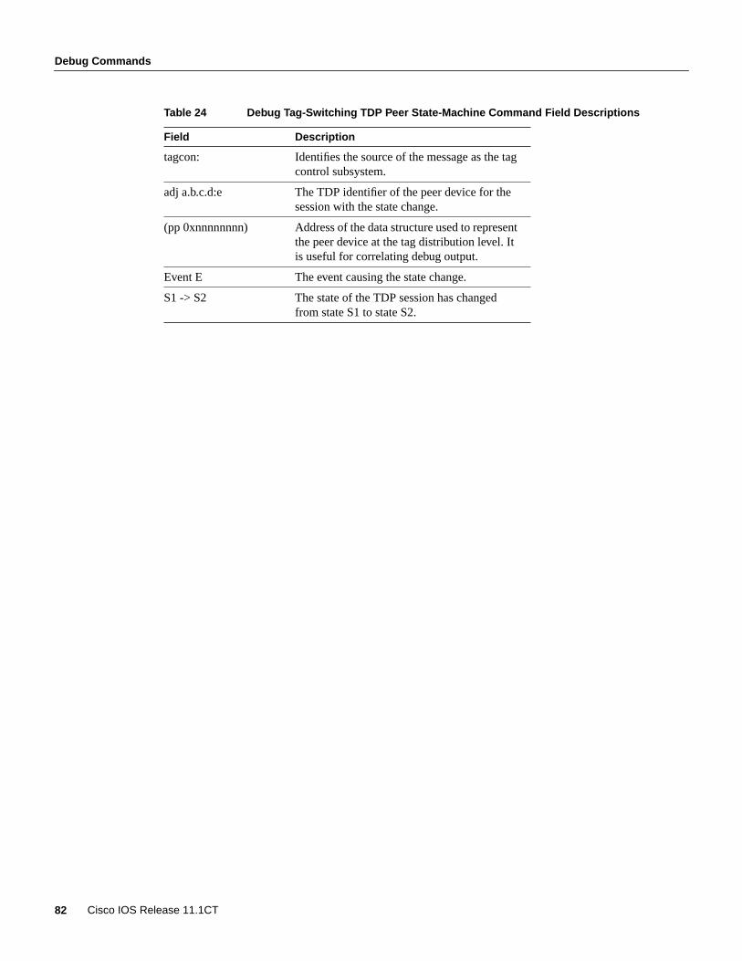
Debug Commands
82 Cisco IOS Release 11.1CT
Table 24 Debug Tag-Switching TDP Peer State-Machine Command Field Descriptions
Field Description
tagcon: Identifies the source of the message as the tagcontrol subsystem.
adj a.b.c.d:e The TDP identifier of the peer device for thesession with the state change.
(pp 0xnnnnnnnn) Address of the data structure used to representthe peer device at the tag distribution level. Itis useful for correlating debug output.
Event E The event causing the state change.
S1 -> S2 The state of the TDP session has changedfrom state S1 to state S2.

Debug Commands
Tag Switching on Cisco 7000 Family 83
debug tag-switching tdp pies receivedUse thedebug tag-switching tdp pies receivedEXEC command to print information about TDPprotocol information elements (PIEs) received from TDP peer devices. Theno form of thiscommand disables debugging output.
[no] debug tag-switching tdp pies received[all]
Syntax Description
Usage GuidelinesTDP requires periodic transmission of keep alive PIEs. If you do not specify theall option, periodickeep alive PIEs are not displayed.
Sample DisplayThe following is an example of the display you see when you enterdebug tag-switching tdp piesreceived:
Router# debug tag tdp pies received all
tdp: Rcvd open PIE from 202.0.0.1 (pp 0x0)tdp: Rcvd keep_alive PIE from 202.0.0.1:1 (pp 0x0)tdp: Rcvd request_bind PIE from 202.0.0.1:1 (pp 0x60DAC678)tdp: Rcvd request_bind PIE from 202.0.0.1:1 (pp 0x60DAC678)tdp: Rcvd open PIE from 210.9.0.9 (pp 0x0)tdp: Rcvd keep_alive PIE from 210.9.0.9:0 (pp 0x0)tdp: Rcvd bind PIE from 202.0.0.1:1 (pp 0x60DAC678)tdp: Rcvd bind PIE from 202.0.0.1:1 (pp 0x60DAC678)
Table 25 lists the significant fields in this display.
Table 25 Debug Tag-Switching TDP Pies Received All Command Field Descriptions
Related Commandsdebug tag-switching tdp pies sent
all (Optional.) TDP received PIEs, including periodic keep alive PIEs.
Field Description
tdp: Identifies the source of the message as TDP.
Rcvd xxx PIE The type of PIE received.
from a.b.c.d The host that sent the PIE. Used in the earlystages of the opening of a TDP session, whenthe TDP identifier is not yet known.
from a.b.c.d:e The TDP identifier of the peer device that sentthe PIE.
(pp 0xnnnnnnnn) Identifies the data structure used to representthe peer device at the tag distribution level.Useful for correlating debug output.
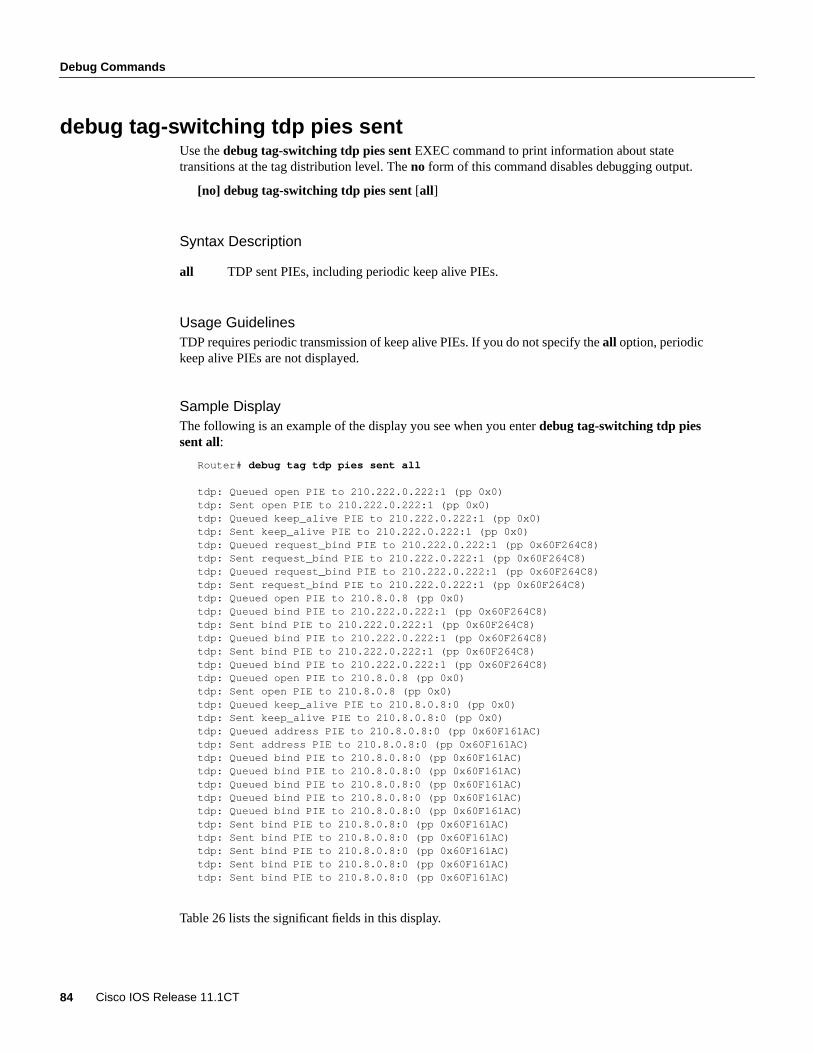
Debug Commands
84 Cisco IOS Release 11.1CT
debug tag-switching tdp pies sentUse thedebug tag-switching tdp pies sentEXEC command to print information about statetransitions at the tag distribution level. Theno form of this command disables debugging output.
[no] debug tag-switching tdp pies sent[all]
Syntax Description
Usage GuidelinesTDP requires periodic transmission of keep alive PIEs. If you do not specify theall option, periodickeep alive PIEs are not displayed.
Sample DisplayThe following is an example of the display you see when you enterdebug tag-switching tdp piessent all:
Router# debug tag tdp pies sent all
tdp: Queued open PIE to 210.222.0.222:1 (pp 0x0)tdp: Sent open PIE to 210.222.0.222:1 (pp 0x0)tdp: Queued keep_alive PIE to 210.222.0.222:1 (pp 0x0)tdp: Sent keep_alive PIE to 210.222.0.222:1 (pp 0x0)tdp: Queued request_bind PIE to 210.222.0.222:1 (pp 0x60F264C8)tdp: Sent request_bind PIE to 210.222.0.222:1 (pp 0x60F264C8)tdp: Queued request_bind PIE to 210.222.0.222:1 (pp 0x60F264C8)tdp: Sent request_bind PIE to 210.222.0.222:1 (pp 0x60F264C8)tdp: Queued open PIE to 210.8.0.8 (pp 0x0)tdp: Queued bind PIE to 210.222.0.222:1 (pp 0x60F264C8)tdp: Sent bind PIE to 210.222.0.222:1 (pp 0x60F264C8)tdp: Queued bind PIE to 210.222.0.222:1 (pp 0x60F264C8)tdp: Sent bind PIE to 210.222.0.222:1 (pp 0x60F264C8)tdp: Queued bind PIE to 210.222.0.222:1 (pp 0x60F264C8)tdp: Queued open PIE to 210.8.0.8 (pp 0x0)tdp: Sent open PIE to 210.8.0.8 (pp 0x0)tdp: Queued keep_alive PIE to 210.8.0.8:0 (pp 0x0)tdp: Sent keep_alive PIE to 210.8.0.8:0 (pp 0x0)tdp: Queued address PIE to 210.8.0.8:0 (pp 0x60F161AC)tdp: Sent address PIE to 210.8.0.8:0 (pp 0x60F161AC)tdp: Queued bind PIE to 210.8.0.8:0 (pp 0x60F161AC)tdp: Queued bind PIE to 210.8.0.8:0 (pp 0x60F161AC)tdp: Queued bind PIE to 210.8.0.8:0 (pp 0x60F161AC)tdp: Queued bind PIE to 210.8.0.8:0 (pp 0x60F161AC)tdp: Queued bind PIE to 210.8.0.8:0 (pp 0x60F161AC)tdp: Sent bind PIE to 210.8.0.8:0 (pp 0x60F161AC)tdp: Sent bind PIE to 210.8.0.8:0 (pp 0x60F161AC)tdp: Sent bind PIE to 210.8.0.8:0 (pp 0x60F161AC)tdp: Sent bind PIE to 210.8.0.8:0 (pp 0x60F161AC)tdp: Sent bind PIE to 210.8.0.8:0 (pp 0x60F161AC)
Table 26 lists the significant fields in this display.
all TDP sent PIEs, including periodic keep alive PIEs.
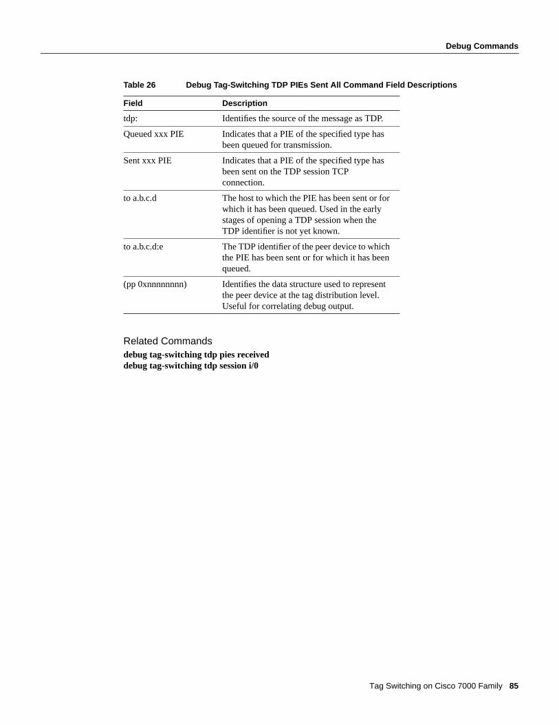
Debug Commands
Tag Switching on Cisco 7000 Family 85
Table 26 Debug Tag-Switching TDP PIEs Sent All Command Field Descriptions
Related Commandsdebug tag-switching tdp pies receiveddebug tag-switching tdp session i/0
Field Description
tdp: Identifies the source of the message as TDP.
Queued xxx PIE Indicates that a PIE of the specified type hasbeen queued for transmission.
Sent xxx PIE Indicates that a PIE of the specified type hasbeen sent on the TDP session TCPconnection.
to a.b.c.d The host to which the PIE has been sent or forwhich it has been queued. Used in the earlystages of opening a TDP session when theTDP identifier is not yet known.
to a.b.c.d:e The TDP identifier of the peer device to whichthe PIE has been sent or for which it has beenqueued.
(pp 0xnnnnnnnn) Identifies the data structure used to representthe peer device at the tag distribution level.Useful for correlating debug output.

Debug Commands
86 Cisco IOS Release 11.1CT
debug tag-switching tdp session ioUse thedebug tag-switching tdp session ioEXEC command to print the contents of TDP PIEs sentto and received from TDP peer devices. Theno form of this command disables debugging output.
[no] debug tag-switching tdp session io[all]
Syntax Description
Usage GuidelinesTDP sessions are supported by data structures and state machines at three levels:
• Transport—TCP connections used to support TDP sessions are established and maintained at thetransport level.
• Protocol—The protocol level implements the TDP session setup protocol, and constructs andparses TDP PDUs and PIEs.
• Tag distribution—The tag distribution level uses TDP sessions to exchange tags with TDP peerdevices.
Thedebug tag-switching tdp transport commands provide visibility of activity at the transportlevel, thedebug tag-switching tdp session commands at the protocol level, and thedebugtag-switching tdp peer commands at the tag distribution level.
TDP requires periodic transmission of keep alive PIEs. If you do not specify theall option, periodickeep alive PIEs are not displayed.
Sample DisplayThe following is an example of the display you see when you enterdebug tag-switching tdp sessionio:
Router# debug tag-switching tdp session io all
tdp: Rcvd open PIE from 210.9.0.9 (pp 0x0)tdp: TDP open PIE: PDU hdr: TDP Id: 210.9.0.9:0; PIE Contents: 0x00 0x01 0x00 0x10 0xD2 0x09 0x00 0x09 0x00 0x00 0x00 0x00 0x01 0x00 0x00 0x04 0x01 0x00 0x00 0x1Etdp: Sent open PIE to 210.9.0.9:0 (pp 0x0)tdp: TDP open PIE: PDU hdr: TDP Id: 172.27.32.28:0; PIE Contents: 0x00 0x01 0x00 0x10 0xAC 0x1B 0x20 0x1C 0x00 0x00 0x00 0x00 0x01 0x00 0x00 0x04 0x01 0x00 0x00 0x0Ftdp: Sent keep_alive PIE to 210.9.0.9:0 (pp 0x0)tdp: TDP keep_alive PIE: PDU hdr: TDP Id: 172.27.32.28:0; PIE Contents: 0x00 0x01 0x00 0x0C 0xAC 0x1B 0x20 0x1C 0x00 0x00 0x00 0x00 0x05 0x00 0x00 0x00tdp: Rcvd keep_alive PIE from 210.9.0.9:0 (pp 0x0)tdp: TDP keep_alive PIE: PDU hdr: TDP Id: 210.9.0.9:0; PIE Contents: 0x00 0x01 0x00 0x0C 0xD2 0x09 0x00 0x09 0x00 0x00 0x00 0x00 0x05 0x00 0x00 0x00tdp: Rcvd address PIE from 210.9.0.9:0 (pp 0x60E109F0)tdp: TDP address PIE: PDU hdr: TDP Id: 210.9.0.9:0; PIE Contents: 0x00 0x01 0x00 0x35 0xD2 0x09 0x00 0x09 0x00 0x00 0x00 0x00 0x08 0x00 0x00 0x29 0x00 0x01 0x00 0x03 0x00 0x23 0x20 0x63 0x65 0x00 0x09 0x20 0xAC 0x1B 0x20 0x1D 0x20 0x0A 0x69 0x00 0x09 0x20 0x0A 0x5C 0x00 0x09 0x20 0x0A 0x6F 0x00 0x09 0x20 0x0A 0xCD 0x00 0x09 0x20 0xD2 0x09 0x00 0x09tdp: Rcvd bind PIE from 210.9.0.9:0 (pp 0x60E109F0)tdp: TDP bind PIE: PDU hdr: TDP Id: 210.9.0.9:0; PIE Contents:
all (Optional.) TDP session I/O activity, including I/O for periodic keep alives.

Debug Commands
Tag Switching on Cisco 7000 Family 87
0x00 0x01 0x00 0xFC 0xD2 0x09 0x00 0x09 0x00 0x00 0x00 0x00 0x02 0x00 0x00 0xF0 0x00 0x00 0x00 0x00 0x00 0x01 0x00 0x02 0x00 0xE6 0x00 0x00 0x00 0x00 0x01 0x10 0x0A 0x6F 0x00 0x00 0x00 0x00 0x01 0x16 0xAC 0x1B 0x20 0x00 0x00 0x00 0x00 0x01 0x10 0xD2 0x09 0x00 0x00 0x00 0x00 0x1A 0x20 0x0A 0x0B 0x00 0x0B 0x00 0x00 0x00
Table 27 lists the significant fields in this display.
Table 27 Debug Tag-Switching TDP Session IO Command Field Descriptions
Related Commandsdebug tag-switching tdp pies receiveddebug tag-switching tdp pies sent
Field Description
tdp: Identifies the source of the message as TDP.
Rcvd xxx PIE Indicates that a PIE of the specified type hasbeen received.
from a.b.c.d The host to which the PIE has been sent.Used in the early stages of the opening of aTDP session when the TDP identifier is notyet known.
Sent xxx PIE Indicates that a PIE of the specified type hasbeen sent.
to a.b.c.d The host to which the PIE has been sent.Used in the early stages of opening a TDPsession when the TDP identifier is not yetknown.
to a.b.c.d:e The TDP identifier of the peer device to whichthe PIE has been sent.
(pp 0xnnnnnnnn) Identifies the data structure used to representthe peer device at the tag distribution level.Useful for correlating debug output.
--TDP xxx PIE The type of PIE that has been sent.
PDU_hdr: TDP Id: a.b.c.d:e The TDP identifier of the sender included inthe TDP PDU header.
PIE contents: 0xnn ... 0xnn The contents of the PIE represented as asequence of bytes.

Debug Commands
88 Cisco IOS Release 11.1CT
debug tag-switching tdp session state-machineUse thedebug tag-switching tdp session state-machineEXEC command to print informationabout state transitions at the protocol level. Theno form of this command disables debugging output.
[no] debug tag-switching tdp session state-machine
Usage GuidelinesTDP sessions are supported by data structures and state machines at three levels:
• Transport—TCP connections used to support TDP sessions are established and maintained at thetransport level.
• Protocol—The protocol level implements the TDP session setup protocol, and constructs andparses TDP PDUs and PIEs.
• Tag distribution—The tag distribution level uses TDP sessions to exchange tags with TDP peerdevices.
Thedebug tag-switching tdp transport commands provide visibility of activity at the transportlevel, thedebug tag-switching tdp session commands at the protocol level, and thedebugtag-switching tdp peer commands at the tag distribution level.
Sample DisplayThe following is an example of the display you see when you enterdebug tag-switching tdp sessionstate-machine:
Router# debug tag-switching tdp session state-machine
tdp: adj:210.9.0.9(0x60DDBB4C): Event: Xport opened; Non-existent -> Init pasvtdp: tdp_create_ptcl_adj: tp = 0x60DDBB4C, ipaddr = 210.9.0.9tdp: adj:210.9.0.9(0x60DDBB4C): Event: Xport opened; Init pasv -> Init pasvtdp: adj:10.105.0.9(0x60DDBB4C): Event: Rcv TDP Open; Init pasv -> Open rcvd pasvtdp: adj:10.105.0.9(0x60DDBB4C): Event: Rcv TDP KA; Open rcvd pasv -> Opertdp: adj:unknown(0x60DDBB4C): Event: Xport closed; Oper -> Non-existent
Table 28 lists the significant fields in this display.
Table 28 Debug Tag-Switching TDP Session State-Machine Field Descriptions
Field Description
tdp: Identifies the source of the message as TDP.
adj:a.b.c.d Identifies the network address of the TDP peerdevice.
(0xnnnnnnnn) Identifies the data structure used to representthe peer device at the protocol level. Usefulfor correlating debug output.
Event: E The event that caused the state transition.

Debug Commands
Tag Switching on Cisco 7000 Family 89
S1 -> S2 The state of the TDP session has changedfrom state S1 to state S2.
Field Description
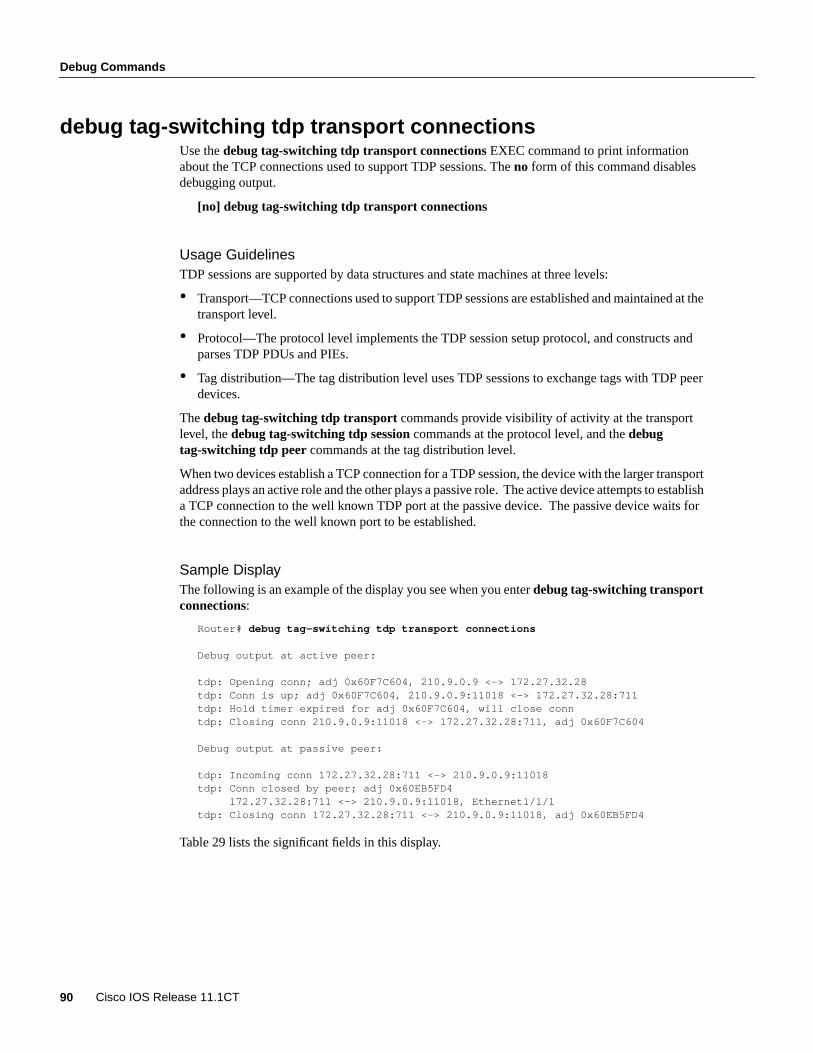
Debug Commands
90 Cisco IOS Release 11.1CT
debug tag-switching tdp transport connectionsUse thedebug tag-switching tdp transport connectionsEXEC command to print informationabout the TCP connections used to support TDP sessions. Theno form of this command disablesdebugging output.
[no] debug tag-switching tdp transport connections
Usage GuidelinesTDP sessions are supported by data structures and state machines at three levels:
• Transport—TCP connections used to support TDP sessions are established and maintained at thetransport level.
• Protocol—The protocol level implements the TDP session setup protocol, and constructs andparses TDP PDUs and PIEs.
• Tag distribution—The tag distribution level uses TDP sessions to exchange tags with TDP peerdevices.
Thedebug tag-switching tdp transport commands provide visibility of activity at the transportlevel, thedebug tag-switching tdp session commands at the protocol level, and thedebugtag-switching tdp peer commands at the tag distribution level.
When two devices establish a TCP connection for a TDP session, the device with the larger transportaddress plays an active role and the other plays a passive role. The active device attempts to establisha TCP connection to the well known TDP port at the passive device. The passive device waits forthe connection to the well known port to be established.
Sample DisplayThe following is an example of the display you see when you enterdebug tag-switching transportconnections:
Router# debug tag-switching tdp transport connections
Debug output at active peer:
tdp: Opening conn; adj 0x60F7C604, 210.9.0.9 <-> 172.27.32.28tdp: Conn is up; adj 0x60F7C604, 210.9.0.9:11018 <-> 172.27.32.28:711tdp: Hold timer expired for adj 0x60F7C604, will close conntdp: Closing conn 210.9.0.9:11018 <-> 172.27.32.28:711, adj 0x60F7C604
Debug output at passive peer:
tdp: Incoming conn 172.27.32.28:711 <-> 210.9.0.9:11018tdp: Conn closed by peer; adj 0x60EB5FD4 172.27.32.28:711 <-> 210.9.0.9:11018, Ethernet1/1/1tdp: Closing conn 172.27.32.28:711 <-> 210.9.0.9:11018, adj 0x60EB5FD4
Table 29 lists the significant fields in this display.
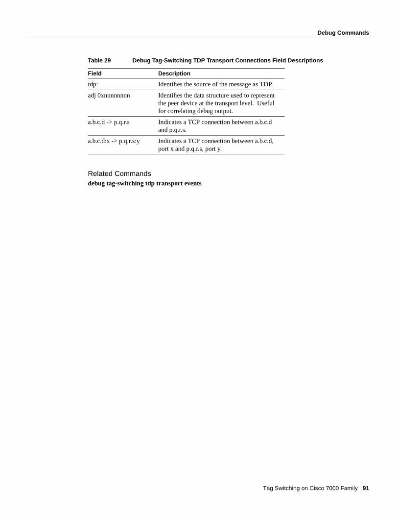
Debug Commands
Tag Switching on Cisco 7000 Family 91
Table 29 Debug Tag-Switching TDP Transport Connections Field Descriptions
Related Commandsdebug tag-switching tdp transport events
Field Description
tdp: Identifies the source of the message as TDP.
adj 0xnnnnnnnn Identifies the data structure used to representthe peer device at the transport level. Usefulfor correlating debug output.
a.b.c.d -> p.q.r.s Indicates a TCP connection between a.b.c.dand p.q.r.s.
a.b.c.d:x -> p.q.r.s:y Indicates a TCP connection between a.b.c.d,port x and p.q.r.s, port y.

Debug Commands
92 Cisco IOS Release 11.1CT
debug tag-switching tdp transport eventsUse thedebug tag-switching tdp transport eventsEXEC command to print information about theevents related to the TDP peer discovery mechanism, which is used to determine the devices withwhich to establish TDP sessions. Theno form of this command disables debugging output.
[no] debug tag-switching tdp transport events
Usage GuidelinesTDP sessions are supported by data structures and state machines at three levels:
• Transport—TCP connections used to support TDP sessions are established and maintained at thetransport level.
• Protocol—The protocol level implements the TDP session setup protocol, and constructs andparses TDP PDUs and PIEs.
• Tag distribution—The tag distribution level uses TDP sessions to exchange tags with TDP peerdevices.
Thedebug tag-switching tdp transport commands provide visibility of activity at the transportlevel, thedebug tag-switching tdp session commands at the protocol level, and thedebugtag-switching tdp peer commands at the tag distribution level.
Sample DisplayThe following is an example of the display you see when you enter debug tag-switching tdptransport events:
Router# debug tag tdp transport events
tdp: Rcvd hello; Ethernet1/1/1, from 10.105.0.9 (210.9.0.9:0), intf_id 0, opt 0x4tdp: Hello from 10.105.0.9 (210.9.0.9:0) to 255.255.255.255, opt 0x4tdp: New adj 0x60DF6E50 from 10.105.0.9 (210.9.0.9:0), Ethernet1/1/1tdp: Rcvd hello; ATM3/0.1, from 200.26.0.4 (202.0.0.1:1), intf_id 1, opt 0x4, tcatmtdp: Rcvd hello; Ethernet1/1/1, from 10.105.0.9 (210.9.0.9:0), intf_id 0, opt 0x4tdp: Hello from 10.105.0.9 (210.9.0.9:0) to 255.255.255.255, opt 0x4tdp: Ignore Hello Timer for Ethernet1/1/1; intf not TDP readytdp: Send hello; Ethernet1/1/1, src/dst 10.105.0.8/255.255.255.255, inst_id 0tdp: Incoming conn 172.27.32.28:711 <-> 210.9.0.9:11019tdp: Found adj 0x60DF6E50 for 210.9.0.9 (Hello xport addr opt)tdp: New temporary adj 0x61033D38 from 210.9.0.9tdp: Real adj 0x60DF6E50 bound to 210.9.0.9:0, replacing temp adj 0x61033D38tdp: Adj 0x61033D38; state set to closedtdp: Rcvd hello; Ethernet1/1/1, from 10.105.0.9 (210.9.0.9:0), intf_id 0, opt 0x4tdp: Rcvd hello; ATM3/0.1, from 200.26.0.4 (202.0.0.1:1), intf_id 1, opt 0x4, tcatmtdp: Send hello; ATM3/0.1, src/dst 99.101.0.8/255.255.255.255, inst_id 1, tcatmtdp: Rcvd hello; Ethernet1/1/1, from 10.105.0.9 (210.9.0.9:0), intf_id 0, opt 0x4tdp: Send hello; Ethernet1/1/1, src/dst 10.105.0.8/255.255.255.255, inst_id 0tdp: Rcvd hello; ATM3/0.1, from 200.26.0.4 (202.0.0.1:1), intf_id 1, opt 0x4, tcatm
Table 30 lists the significant fields in this display.
Table 30 Debug Tag-Switching TDP Transport Events Field Descriptions
Field Description
tdp: Identifies the source of the message as TDP.
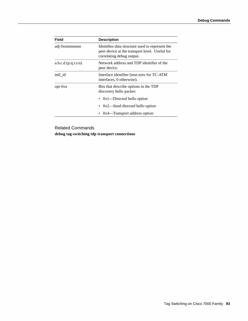
Debug Commands
Tag Switching on Cisco 7000 Family 93
Related Commandsdebug tag-switching tdp transport connections
adj 0xnnnnnnnn Identifies data structure used to represent thepeer device at the transport level. Useful forcorrelating debug output.
a.b.c.d (p.q.r.s:n) Network address and TDP identifier of thepeer device.
intf_id Interface identifier (non-zero for TC-ATMinterfaces, 0 otherwise).
opt 0xn Bits that describe options in the TDPdiscovery hello packet:
• 0x1—Directed hello option
• 0x2—Send directed hello option
• 0x4—Transport address option
Field Description

Debug Commands
94 Cisco IOS Release 11.1CT
debug tag-switching tdp transport timersUse thedebug tag-switching tdp transport timersEXEC command to print information aboutevents that restart the "hold" timers that are part of the TDP discovery mechanism. Theno form ofthis command disables debugging output.
[no] debug tag-switching tdp transport timers
Usage GuidelinesTDP sessions are supported by data structures and state machines at three levels:
• Transport—TCP connections used to support TDP sessions are established and maintained at thetransport level.
• Protocol—The protocol level implements the TDP session setup protocol. The construction andparsing of TDP PDUs and PIEs occur at this level.
• Tag distribution—The tag distribution level uses TDP sessions to exchange tags with TDP peerdevices.
Thedebug tag-switching tdp transport commands provide visibility of activity at the transportlevel, thedebug tag-switching tdp session commands at the protocol level, and thedebugtag-switching tdp peer commands at the tag distribution level.
Sample DisplayThe following is an example of the display you see when you enterdebug tag-switching tdptransport timers:
Router# debug tag-switching tdp transport timers
tdp: Start holding timer; adj 0x60D5BC10, 200.26.0.4tdp: Start holding timer; adj 0x60EA9360, 10.105.0.9tdp: Start holding timer; adj 0x60D5BC10, 200.26.0.4tdp: Start holding timer; adj 0x60EA9360, 10.105.0.9tdp: Start holding timer; adj 0x60D5BC10, 200.26.0.4tdp: Start holding timer; adj 0x60EA9360, 10.105.0.9
Table 31 lists the significant fields in this display.
Table 31 Debug Tag-Switching TDP Transport Timers Command Field Descriptions
Related Commandsdebug tag-switching tdp transport events
Field Description
tdp Identifies the source of the message as TDP.
adj 0xnnnnnnnn Identifies the data structure used to representthe peer device at the transport level.
a.b.c.d Network address of the peer device.

Debug Commands
Tag Switching on Cisco 7000 Family 95
debug tag-switching tfib cefUse thedebug tag-switching tfib cefEXEC command to print detailed information about tagrewrites being created, resolved, and deactivated as CEF routes are added, changed, or removed. Theno form of this command disables debugging.
[no] debug tag-switching tfib cef
Usage GuidelinesSeveral lines of output are produced for each route placed into the TFIB. If your router has thousandsof tagged routes, be careful about issuing this command. When Tag Switching is first enabled, eachof these routes is placed into the TFIB. Ifdebug tag-switching tfib cefhas been issued, several linesof output are displayed for each route.
Sample DisplayThe following is an example of the display you see when you enterdebug tag-switching tfib cef
Router# debug tag-switching tfib cef
Cisco Express Forwarding related TFIB services debugging is on
tagcon: tc_ip_rtlookup fail on 10.0.0.0/8:subnet_lookup failedTFIB: route tag chg 10.7.0.7/32,idx=1,inc=Withdrn,outg=Withdrn,enabled=0x2TFIB: fib complete delete: prefix=10.7.0.7/32,inc tag=26,delete_info=1TFIB: deactivate tag rew for 10.7.0.7/32,index=0TFIB: set fib rew: pfx 10.7.0.7/32,index=0,add=0,tag_rew->adj=Ethernet2/3TFIB: resolve tag rew,prefix=10.7.0.7/32,no tag_info,no parentTFIB: fib scanner start:needed:1,unres:0,mac:0,loadinfo:0TFIB: resolve tag rew,prefix=10.7.0.7/32,no tag_info,no parentTFIB: fib upd loadinf 10.100.100.100/32,tag=Tun_hd,fib no loadin,tfib no loadinTFIB: fib check cleanup for 10.100.100.100/32,index=0,return_value=0TFIB: fib_scanner_endTFIB: create dynamic entry for 10.11.0.11/32TFIB: call find_route_tags,dist_method=1,next_hop=10.93.0.11,Et2/3TFIB: route tag chg 10.11.0.11/32,idx=0,inc=26,outg=Unkn,enabled=0x3TFIB: create tag info 10.11.0.11/32,inc tag=26,has no infoTFIB: resolve tag rew,prefix=10.11.0.11/32,has tag_info,no parentTFIB: finish fib res 10.11.0.11/32:index 0,parent outg tag no parentTFIB: fib upd loadinf 10.11.0.11/32,tag=26,fib no loadin,tfib no loadinTFIB: set fib rew: pfx 10.11.0.11/32,index=0,add=1,tag_rew->adj=Ethernet2/3tagcon: route_tag_change for: 10.250.0.97/32 intag 33, outtag 28, nexthop tsr 10.11.0.11:0TFIB: route tag chg 10.250.0.97/32,idx=0,inc=33,outg=28,enabled=0x3TFIB: deactivate tag rew for 10.250.0.97/32,index=0TFIB: set fib rew: pfx 10.250.0.97/32,index=0,add=0,tag_rew->adj=Ethernet2/3TFIB: create tag info 10.250.0.97/32,inc tag=33,has old infoOn VIP:TFIB: route tag chg 10.13.72.13/32,idx=0,inc=34,outg=Withdrn,enabled=0x3TFIB: deactivate tag rew for 10.13.72.13/32,index=0TFIB: set fib rew: pfx 10.13.72.13/32,index=0,add=0,tag_rew->adj=TFIB: create tag info 10.13.72.13/32,inc tag=34,has old infoTFIB: resolve tag rew,prefix=10.13.72.13/32,has tag_info,no parentTFIB: finish fib res 10.13.72.13/32:index 0,parent outg tag no parentTFIB: set fib rew: pfx 10.100.100.100/32,index=0,add=0,tag_rew->adj=TFIB: create tag info 10.100.100.100/32,inc tag=37,has old infoTFIB: resolve tag rew,prefix=10.100.100.100/32,has tag_info,no parentTFIB: finish fib res 10.100.100.100/32:index 0,parent outg tag no parentTFIB: fib upd loadinf 10.100.100.100/32,tag=37,fib no loadin,tfib no loadin

Debug Commands
96 Cisco IOS Release 11.1CT
Table 32 lists the significant fields in this display. See Table 34 for a description of special tag namesseen in the debug output.
Table 32 Debug Tag-Switching TFIB CEF Command Field Descriptions
Field Description
TFIB The name of the subsystem issuing the debug output
tagcon The name of subsystem issuing the debug output (TagControl)
tc_ip_rtlookup fail on x.y.w.z/m:subnet_lookup failed
The destination with IP address and mask shown is notin the Routing Table
route tag chg x.y.w.z/m Request to create TFIB entry for specified prefix/mask
idx=-1 The index within FIB entry of the path whose TFIBentry is being created. -1 means all paths for this FIBentry.
inc=s Incoming tag of entry being processed
outg=s Outgoing tag of entry being processed
enabled=0xn Bit mask indicating types of Tag Switching currentlyenabled (0x1 = dynamic, 0x2 = TSP tunnels, 0x3 =both)
fib complete delete Indicates FIB entry being deleted
prefix=x.y.w.z/m A destination prefix
delete_info=1 Indicates that tag_info is also being deleted
deactivate tag rew for x.y.w.z/m Indicates tag rewrite for specified prefix is beingdeleted
index=n Index of path in FIB entry being processed
set fib rew: pfx x.y.w.z/m Indicates tag rewrite is being installed or deleted fromthe FIB entry for the specified destination for tagimposition purposes
add=0 Indicates tag rewrite is being deleted from the FIB (nolonger imposing tag)
tag_rew->adj=s Adjacency of tag_rewrite for tag imposition
resolve tag rew,prefix=x.y.w.z/m Indicates the FIB route to the specified prefix is beingresolved
no tag_info Indicates there is no tag_info for the destination(destination not tagged)
no parent Indicates route is not recursive
fib scanner start Indicates the periodic scan of the FIB has started
needed:1 Indicates TFIB needs the FIB to be scanned
unres:n The number of unresolved TFIB entries
mac:n The number of TFIB entries missing MAC strings

Debug Commands
Tag Switching on Cisco 7000 Family 97
Related Commandsdebug tag-switching tfib enc
loadinfo:n Indicates whether non-recursive accounting state haschanged and thus the loadinfo information in the TFIBneeds to be adjusted
fib upd loadinf x.y.w.z/m Indicates that a check for non-recursive accounting isbeing made and TFIB loadinfo information forspecified prefix is being updated
tag=s Incoming tag of entry
fib no loadin Indicates corresponding FIB entry has no loadinfo
tfib no loadin Indicates TFIB entry has no loadinfo
fib check cleanup for x.y.w.z/m Indicates a check is being made on the TFIB entry forspecified destination to see if rewrite needs to beremoved from TFIB
return_value=x If 0, no change in TFIB entry. If 1, there was a change.
fib_scanner_end FIB scan has come to an end
create dynamic entry forx.y.w.z/m
The TFIB has been enabled and a TFIB entry is beingcreated for the specified destination
call find_route_tags The tags for that destination are being requested
dist_method=n The tag distribution method -- TDP, TC-ATM, and soon.
next_hop=x.y.z.w Next hop for the destination
interface name Outgoing interface for the destination
create tag info A tag_info data structure is being created for thedestination
has no info The destination does not already have a tag_info
finish fib res x.y.z.w/m The TFIB entry for the specified route is beingcompleted
parent outg tag s If recursive, specifies the outgoing tag of the routethrough which it recurses (the parent). If not recursive,s = “no parent”
tagcon: route_tag_change for:x.y.z.w/m
Tag Control is notifying TFIB that tags are available forspecified destination
intag s Incoming tag for the destination
outtag s Outgoing tag for the destination
nexthop tsr x.y.z.w.i TDP ID of next hop which sent the tag
Field Description
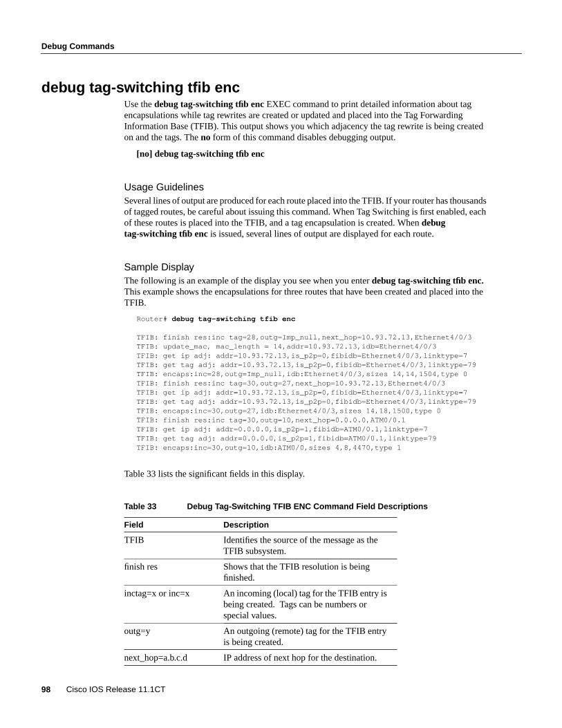
Debug Commands
98 Cisco IOS Release 11.1CT
debug tag-switching tfib encUse thedebug tag-switching tfib enc EXEC command to print detailed information about tagencapsulations while tag rewrites are created or updated and placed into the Tag ForwardingInformation Base (TFIB). This output shows you which adjacency the tag rewrite is being createdon and the tags. The no form of this command disables debugging output.
[no] debug tag-switching tfib enc
Usage GuidelinesSeveral lines of output are produced for each route placed into the TFIB. If your router has thousandsof tagged routes, be careful about issuing this command. When Tag Switching is first enabled, eachof these routes is placed into the TFIB, and a tag encapsulation is created. Whendebugtag-switching tfib enc is issued, several lines of output are displayed for each route.
Sample DisplayThe following is an example of the display you see when you enterdebug tag-switching tfib enc.This example shows the encapsulations for three routes that have been created and placed into theTFIB.
Router# debug tag-switching tfib enc
TFIB: finish res:inc tag=28,outg=Imp_null,next_hop=10.93.72.13,Ethernet4/0/3TFIB: update_mac, mac_length = 14,addr=10.93.72.13,idb=Ethernet4/0/3TFIB: get ip adj: addr=10.93.72.13,is_p2p=0,fibidb=Ethernet4/0/3,linktype=7TFIB: get tag adj: addr=10.93.72.13,is_p2p=0,fibidb=Ethernet4/0/3,linktype=79TFIB: encaps:inc=28,outg=Imp_null,idb:Ethernet4/0/3,sizes 14,14,1504,type 0TFIB: finish res:inc tag=30,outg=27,next_hop=10.93.72.13,Ethernet4/0/3TFIB: get ip adj: addr=10.93.72.13,is_p2p=0,fibidb=Ethernet4/0/3,linktype=7TFIB: get tag adj: addr=10.93.72.13,is_p2p=0,fibidb=Ethernet4/0/3,linktype=79TFIB: encaps:inc=30,outg=27,idb:Ethernet4/0/3,sizes 14,18,1500,type 0TFIB: finish res:inc tag=30,outg=10,next_hop=0.0.0.0,ATM0/0.1TFIB: get ip adj: addr=0.0.0.0,is_p2p=1,fibidb=ATM0/0.1,linktype=7TFIB: get tag adj: addr=0.0.0.0,is_p2p=1,fibidb=ATM0/0.1,linktype=79TFIB: encaps:inc=30,outg=10,idb:ATM0/0,sizes 4,8,4470,type 1
Table 33 lists the significant fields in this display.
Table 33 Debug Tag-Switching TFIB ENC Command Field Descriptions
Field Description
TFIB Identifies the source of the message as theTFIB subsystem.
finish res Shows that the TFIB resolution is beingfinished.
inctag=x or inc=x An incoming (local) tag for the TFIB entry isbeing created. Tags can be numbers orspecial values.
outg=y An outgoing (remote) tag for the TFIB entryis being created.
next_hop=a.b.c.d IP address of next hop for the destination.

Debug Commands
Tag Switching on Cisco 7000 Family 99
Table 34 lists special tags, which sometimes appear in the debug output, and their meanings.
Table 34 Special Tags Seen in Debug Output
Related Commandsdebug tag-switching tfib state
interface The outgoing interface through which apacket will be sent.
get ip adj Shows that the IP adjacency to use in theTFIB entry is being determined.
get tag adj Shows that the tag-switching adjacency touse for the TFIB entry is being determined.
addr = a.b.c.d The IP address of the adjacency.
is_p2p=x If 1, this is a point-to-point adjacency. If 0, itis not.
fibidb = s The interface of the adjacency.
linktype = x The link type of the adjacency (7 = LINK_IPor 79 = LINK_TAG).
sizes x,y,z x = length of macstring, y = length of tagencapsulation, z = tag MTU.
type = x Tag encapsulation type. 0= normal,1 = TCATM, 2 = TSP tunnel.
idb:s Outgoing interface.
update_mac Shows that the macstring of the adjacency isbeing updated.
Special Tag Meaning
Unassn—Inital value No tag assigned yet.
Unused This destination does not have a tag (forexample, a BGP route).
Withdrn The tag for this destination has beenwithdrawn.
Unkn This destination should have a tag, but it isnot known yet.
Get_res A recursive route that will get a tag whenresolved.
Exp_null Explicit null tag—used over TC-ATM.
Imp_null Implicit null tag—for directly connectedroutes.
Tun_hd For head of TSP tunnel.
Field Description
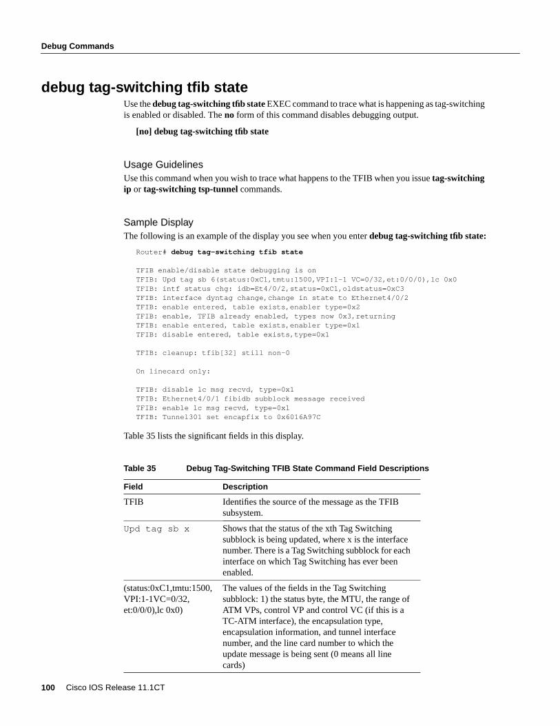
Debug Commands
100 Cisco IOS Release 11.1CT
debug tag-switching tfib stateUse thedebug tag-switching tfib stateEXEC command to trace what is happening as tag-switchingis enabled or disabled. Theno form of this command disables debugging output.
[no] debug tag-switching tfib state
Usage GuidelinesUse this command when you wish to trace what happens to the TFIB when you issuetag-switchingip or tag-switching tsp-tunnel commands.
Sample DisplayThe following is an example of the display you see when you enterdebug tag-switching tfib state:
Router# debug tag-switching tfib state
TFIB enable/disable state debugging is onTFIB: Upd tag sb 6(status:0xC1,tmtu:1500,VPI:1-1 VC=0/32,et:0/0/0),lc 0x0TFIB: intf status chg: idb=Et4/0/2,status=0xC1,oldstatus=0xC3TFIB: interface dyntag change,change in state to Ethernet4/0/2TFIB: enable entered, table exists,enabler type=0x2TFIB: enable, TFIB already enabled, types now 0x3,returningTFIB: enable entered, table exists,enabler type=0x1TFIB: disable entered, table exists,type=0x1
TFIB: cleanup: tfib[32] still non-0
On linecard only:
TFIB: disable lc msg recvd, type=0x1TFIB: Ethernet4/0/1 fibidb subblock message receivedTFIB: enable lc msg recvd, type=0x1TFIB: Tunnel301 set encapfix to 0x6016A97C
Table 35 lists the significant fields in this display.
Table 35 Debug Tag-Switching TFIB State Command Field Descriptions
Field Description
TFIB Identifies the source of the message as the TFIBsubsystem.
Upd tag sb x Shows that the status of the xth Tag Switchingsubblock is being updated, where x is the interfacenumber. There is a Tag Switching subblock for eachinterface on which Tag Switching has ever beenenabled.
(status:0xC1,tmtu:1500,VPI:1-1VC=0/32,et:0/0/0),lc 0x0)
The values of the fields in the Tag Switchingsubblock: 1) the status byte, the MTU, the range ofATM VPs, control VP and control VC (if this is aTC-ATM interface), the encapsulation type,encapsulation information, and tunnel interfacenumber, and the line card number to which theupdate message is being sent (0 means all linecards)

Debug Commands
Tag Switching on Cisco 7000 Family 101
Related Commandsdebug tag-switching tfib encdebug tag-switching tfib statedebug tag-switching tfib struct
intf status change Shows that there was an interface status change.
idb=Et4/0/2 The interface whose status changed.
status=0xC1 The new status bits in the Tag Switching subblockof the idb.
oldstatus=0xC3 What the old status bits were before the change.
Interface dyntag change,change in state toEthernet4/0/2
Shows that there was a change in dynamic tagstatus for the particular interface.
enable entered Shows that the code that enables the TFIB wasinvoked.
TFIB already enabled Shows that TFIB was already enabled when thiscall was made.
table exists Shows that a TFIB table had already been allocatedin a previous call.
cleanup: tfib[x] stillnon-0
Indicates TFIB is in the process of being deleted,but that slot x is still around.
disable lc mesg recvd,type=0x1
Shows that a message to disable Tag Switching type1 (dynamic) was received by the line card.
disable entered, tableexists,type=0x1
Shows that a call to disable dynamic Tag Switchingwas issued.
Ethernet4/0/1 fibidbsubblock messagereceived
Shows that a message giving fibidb status changewas received on the lc.
enable lc msgrecvd,type=0x1
Shows that a message to enable Tag Switching type1 (dynamic) was received by the line card.
Tunnel301 set encapfixto 0x6016A97C
Shows that fibidb Tunnel301 on the line cardreceived an encapsulation fixup.
types now 0x3, returning Gives the value of the bitmask indicating the type ofTag Switching enabled. 0x1 means dynamic TagSwitching; 0x2 means tsp-tunnels; and 0x3 meansboth.
Field Description

Debug Commands
102 Cisco IOS Release 11.1CT
debug tag-switching tfib structUse thedebug tag-switching tfib structEXEC command to trace the allocation and freeing ofTFIB-related data structures—the TFIB itself, tag-rewrites, and tag-info data. Theno form of thiscommand disables debugging output.
[no] debug tag-switching tfib struct
Sample DisplayThe following is an example of the display you see when you enterdebug tag-switching tfib struct.
Router# debug tag-switching tfib struct
TFIB data structure changes debugging is on
TFIB: delete tag rew, incoming tag 32TFIB: remove from tfib,inc tag=32TFIB: set loadinfo,tag=32,no old loadinfo,no new loadinfoTFIB: TFIB not in use. Checking for entries.TFIB: cleanup: tfib[0] still non-0TFIB: remove from tfib,inc tag=Tun_hdTFIB: set loadinfo,tag=Exp_null,no old loadinfo,no new loadinfoTFIB: TFIB freed.TFIB: enable, TFIB allocated, size 4024 bytes, maxtag = 500TFIB: create tag rewrite: inc Tun_hd,outg UnknTFIB: add to tfib at Tun_hd, first in circular list, mac=0,enc=0TFIB: delete tag rew, incoming tag Tun_hdTFIB: remove from tfib,inc tag=Tun_hdTFIB: set loadinfo,tag=Exp_null,no old loadinfo,no new loadinfoTFIB: create tag rewrite: inc Tun_hd,outg UnknTFIB: add to tfib at Tun_hd, first in circular list, mac=0,enc=0TFIB: create tag rewrite: inc 26,outg UnknTFIB: add to tfib at 26, first in circular list, mac=0,enc=0TFIB: add to tfib at 27, added to circular list, mac=0,enc=0TFIB: delete tag rew, incoming tag Tun_hdTFIB: remove from tfib,inc tag=Tun_hdTFIB: set loadinfo,tag=Exp_null,no old loadinfo,no new loadinfoTFIB: add to tfib at 29, added to circular list, mac=4,enc=8TFIB: delete tag rew, incoming tag 29TFIB: remove from tfib,inc tag=29
Table 36 lists the significant fields in this display.
Table 36 Debug Tag-Switching TFIB Struct Command Field Descriptions
Field Description
TFIB The subsystem issuing the message.
delete tag rew A tag_rewrite is being freed.
remove from tfib A tag rewrite is being removed from theTFIB.
inc tag-s The incoming tag of the entry beingprocessed.
set loadinfo The loadinfo field in the TFIB entry is beingset (used for nonrecursive accounting).
tag=s The incoming tag of the entry beingprocessed.

Debug Commands
Tag Switching on Cisco 7000 Family 103
Related Commandstag-switching tfib ceftag-switching tfib enctag-switching tfib state
no old loadinfo The TFIB entry did not have a loadinfobefore.
no new loadinfo The TFIB entry should not have a loadinfonow.
TFIB not is use. Checkingfor entries
Tag Switching has been disabled, and theTFIB is being freed up.
cleanup: tfib[x] stillnon-0
The TFIB is being checked for any entries inuse, and entry x is the lowest numbered slotstill in use.
TFIB freed The TFIB table has been freed.
enable, TFIB allocated,size x bytes, maxtag = y
Tag Switching has been enabled, and a TFIBof x bytes has been allocated. The largestlegal tag is y.
create tag rewrite A tag_rewrite is being created.
inc s The incoming tag.
outg s The outgoing tag.
add to tfib at s A tag_rewrite has been placed in the TFIB atslot s.
first in circular list This TFIB slot had been empty, and this isthe first rewrite in the list.
mac=0,enc=0 Length of the mac string and totalencapsulation length, including tags.
added to circular list A tag_rewrite is being added to a TFIB slotwhich already had an entry. This rewrite isbeing inserted in the circular list.
Field Description

Debug Commands
104 Cisco IOS Release 11.1CT
debug tag-switching tfib tspUse thedebug tag-switching tfib tspEXEC command to print detailed information about tagrewrites being created and deleted as TSP tunnels are added or removed. Theno form of thiscommand disables debugging output.
[no] debug tag-switching tfib tsp
Sample DisplayThe following is an example of the display you see when you enterdebug tag-switching tfib tsp:
Router# debug tag-switching tfib tsp
TSP-tunnel related TFIB services debugging is on
TFIB: tagtun,next hop=10.93.72.13,inc=35,outg=1,idb=Et4/0/3TFIB: tsptunnel:next hop=10.93.72.13,inc=35,outg=Imp_null,if_number=7TFIB: tsptun update loadinfo:tag=35,loadinfo_reqd=0,no new loadinfo,no old loadinfoTFIB: tagtun tag chg linec,fiblc=0,in tg=35,o tg=1,if=7,nh=10.93.72.13TFIB: tagtun,next hop=10.92.0.7,inc=36,outg=1,idb=Et4/0/2TFIB: tsptunnel:next hop=10.92.0.7,inc=36,outg=Imp_null,if_number=6TFIB: tsptun update loadinfo:tag=36,loadinfo_reqd=0,no new loadinfo,no old loadinfoTFIB: tagtun tag chg linec,fiblc=0,in tg=36,o tg=1,if=6,nh=10.92.0.7TFIB: tagtun_delete, inc = 36tagtun tag del linec,itag=12TFIB: tagtun_delete, inc = 35tagtun tag del linec,itag=12TFIB: tagtun,next hop=10.92.0.7,inc=35,outg=1,idb=Et4/0/2TFIB: tsptunnel:next hop=10.92.0.7,inc=35,outg=Imp_null,if_number=6TFIB: tsptun update loadinfo:tag=35,loadinfo_reqd=0,no new loadinfo,no old loadinfoTFIB: tagtun tag chg linec,fiblc=0,in tg=35,o tg=1,if=6,nh=10.92.0.7
On VIP:TFIB: tagtun chg msg,in tg=35,o tg=1,nh=10.93.72.13,if=7TFIB: tsptunnel:next hop=10.93.72.13,inc=35,outg=Imp_null,if_number=7TFIB: tsptun update loadinfo:tag=35,loadinfo_reqd=0,no new loadinfo,no old loadinfoTFIB: tagtun chg msg,in tg=36,o tg=1,nh=10.92.0.7,if=6TFIB: tsptunnel:next hop=10.92.0.7,inc=36,outg=Imp_null,if_number=6TFIB: tsptun update loadinfo:tag=36,loadinfo_reqd=0,no new loadinfo,no old loadinfoTFIB: tagtun chg msg,in tg=35,o tg=1,nh=10.93.72.13,if=7TFIB: tsptunnel:next hop=10.93.72.13,inc=35,outg=Imp_null,if_number=7TFIB: tsptun update loadinfo:tag=35,loadinfo_reqd=0,no new loadinfo,no old loadinfoTFIB: tagtun chg msg,in tg=36,o tg=1,nh=10.92.0.7,if=6TFIB: tsptunnel:next hop=10.92.0.7,inc=36,outg=Imp_null,if_number=6TFIB: tsptun update loadinfo:tag=36,loadinfo_reqd=0,no new loadinfo,no old loadinfoTFIB: tagtun chg msg,in tg=35,o tg=1,nh=10.92.0.7,if=6TFIB: tsptunnel:next hop=10.92.0.7,inc=35,outg=Imp_null,if_number=6TFIB: tsptun update loadinfo:tag=35,loadinfo_reqd=0,no new loadinfo,no old loadinfo
lists the significant fields in this display.
Table 37 Debug Tag-Switching Tfib State Command Field Descriptions
Field Description
tagtun Name of routine entered
next hop=x.y.z.w Next hop for the tunnel being created
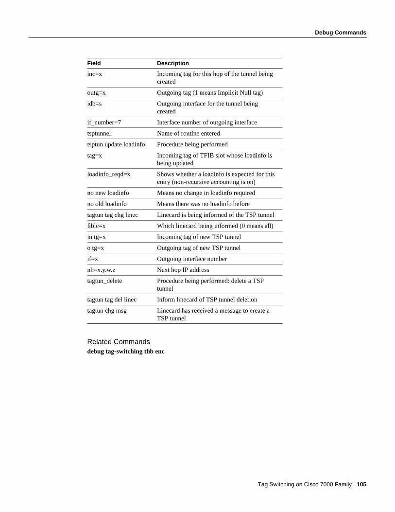
Debug Commands
Tag Switching on Cisco 7000 Family 105
Related Commandsdebug tag-switching tfib enc
inc=x Incoming tag for this hop of the tunnel beingcreated
outg=x Outgoing tag (1 means Implicit Null tag)
idb=s Outgoing interface for the tunnel beingcreated
if_number=7 Interface number of outgoing interface
tsptunnel Name of routine entered
tsptun update loadinfo Procedure being performed
tag=x Incoming tag of TFIB slot whose loadinfo isbeing updated
loadinfo_reqd=x Shows whether a loadinfo is expected for thisentry (non-recursive accounting is on)
no new loadinfo Means no change in loadinfo required
no old loadinfo Means there was no loadinfo before
tagtun tag chg linec Linecard is being informed of the TSP tunnel
fiblc=x Which linecard being informed (0 means all)
in tg=x Incoming tag of new TSP tunnel
o tg=x Outgoing tag of new TSP tunnel
if=x Outgoing interface number
nh=x.y.w.z Next hop IP address
tagtun_delete Procedure being performed: delete a TSPtunnel
tagtun tag del linec Inform linecard of TSP tunnel deletion
tagtun chg msg Linecard has received a message to create aTSP tunnel
Field Description

Debug Commands
106 Cisco IOS Release 11.1CT
debug tag-switching traffic-engineeringUse thedebug tag-switching traffic-engineeringEXEC command to print information aboutevents affecting the traffic engineering routing process. Theno form of this command disablesdebugging output.
[no] debug tag-switching traffic-engineering [events]
Syntax Description
Sample DisplayThe following is an example of the display you see when you enterdebug tag-switchingtraffic-engineering events:
Router# debug tag-switching traffic-engineering events
te_events: event signalled
te_events: traffeng timer
te_events: re-evaluating prefix 1.1.1.1/32
te_events: re-evaluating prefix 2.2.2.2/32
Table 38 lists the significant fields in this display.
Table 38 Debug Tag-Switching Traffic-Engineering Events Command FieldDescriptions
Related Commandsshow ip traffic-engineering
events Events signalled to the traffic engineering routingprocess, periodic timers, and reevaluations of trafficengineering routes.
Field Description
te_events: Identifies this as a traffic engineering eventsdebug statement.
prefix X/X: Identifies the filter being evaluated.

Debug Commands
Tag Switching on Cisco 7000 Family 107
debug tag-switching traffic-engineering interfacesUse thedebug tag-switching traffic-engineering interfacesEXEC command to print informationabout changes to tunnels configured with traffic engineering routes. Theno form of this commanddisables debugging output.
[no] debug tag-switching traffic-engineering interfaces
Usage GuidelinesThe traffic engineering routing process keeps track of tunnels that have traffic engineering routesconfigured through them. This debug command provides information about significant changes(such as up/down transitions) to those tunnels.
Sample DisplayThe following is an example of the display you see when you enterdebug tag-switchingtraffic-engineering interfaces:
Router# debug tag-switching traffic-engineering interfaces
te_intfcs: interface Tunnel12 down notification receivedte_intfcs: Tunnel12 up/down event
Table 38 lists the significant fields in this display.
Table 39 Debug Tag-Switching Traffic-Engineering Interfaces Command FieldDescriptions
Related Commandsshow tag-switching tsp-tunnels
Field Description
te_intfcs: Identifies this as a traffic engineering interfacedebug statement.

Debug Commands
108 Cisco IOS Release 11.1CT
debug tag-switching traffic-engineering metricsUse thedebug tag-switching traffic-engineering metricsEXEC command to print informationabout metric exchange in support of the traffic engineering loop prevention algorithm. Theno formof this command disables debugging output.
[no] debug tag-switching traffic-engineering metrics
Usage GuidelinesMetric exchange is supported by data structures in two areas:
• Adjacency establishment—A TDP adjacency must be established between the head and tail ofthe tunnel, over which metrics can be exchanged.
• Metric exchange—Metrics are actually requested and advertised over the adjacency.
Sample DisplayThe following is an example of the display you see when you enterdebug tag-switchingtraffic-engineering metrics:
Router# debug tag-switching traffic-engineering metrics
Debug output at tunnel head:te_metric: tdp peer 10.11.0.11:0 announced as upte_metric: TEAdj (Head) 10.11.0.11:0 allocated (0x60F72940)te_metric: TunAdj Tunnel13: brought up adj rev 3te_metric: metric 1.1.1.1/32 requested (entry 0x60F5D4FC, refcnt 1)te_metric: metric entry queued for transmit (entry 0x60F5D4FC, type 1, rev 17, adj next0x60F5D4FC)te_metric: metric 2.2.2.2/32 requested (entry 0x60F78920, refcnt 1)te_metric: metric entry queued for transmit (entry 0x60F78920, type 1, rev 18, adj next0x60F5D4FC)te_metric: metric request (mlist type 2) pdu buffered for 10.11.0.11:0te_metric: metric request (mlist type 2) pdu buffered for 10.11.0.11:0te_metric: TEAdj (Head) revision sent updated from 0 to 20te_metric: metric announce pie received from 10.11.0.11:0te_metric: metric announce (mlist type 1) pdu received from 10.11.0.11:0te_metric: metric announce (mlist type 1) pdu received from 10.11.0.11:0

Debug Commands
Tag Switching on Cisco 7000 Family 109
Table 40 lists the significant fields in this display.
Table 40 Debug Tag-Switching Traffic-Engineering Metrics Command FieldDescriptions
Related Commandsshow ip traffic-engineering
Field Description
te_metric: Identifies this as a traffic engineering metricdebug statement.
tdp peer id: Identifies the TDP peer device.
TEAdj (Head) id: Traffic engineering metric exchange state forTDP peer device.
TunAdj: Traffic engineering metric exchange state fortunnel metric.
X/X: Metric record.
entry 0xnnnnnnnn: Identifies the data structure for the metricentry. Useful for correlating debug output.

Debug Commands
110 Cisco IOS Release 11.1CT
debug tag-switching traffic-engineering routing-tableUse thedebug tag-switching traffic-engineering routing-tableEXEC command to printinformation about traffic engineering's interactions with the IP routing table and with the forwardingtable, Cisco Express Forwarding (CEF). Theno form of this command disables debugging output.
[no] debug tag-switching traffic-engineering routing-table
Usage GuidelinesTraffic engineering overrides IP routing table entries in the forwarding table.
Sample DisplayThe following is an example of the display you see when you enterdebug tag-switchingtraffic-engineering routing-table, adding and later deleting a traffic engineering entry from theforwarding table:
Router# debug tag-switching traffic-engineering routing-table
te_rttab: te_rttab add 4.4.4.4/32->Tunnel13te_rttab: te_rttab delete 4.4.4.4/32
Table 41 lists the significant fields in this display.
Table 41 Debug Tag-Switching Traffic-Engineering Routing-Table Command FieldDescriptions
Related Commandsshow ip traffic-engineering
Field Description
te_rttab: Identifies this as a traffic engineering routingtable debug statement.
add/delete: Operation on forwarding table.
X/X: The prefix/mask whose forwarding table entryis being changed.
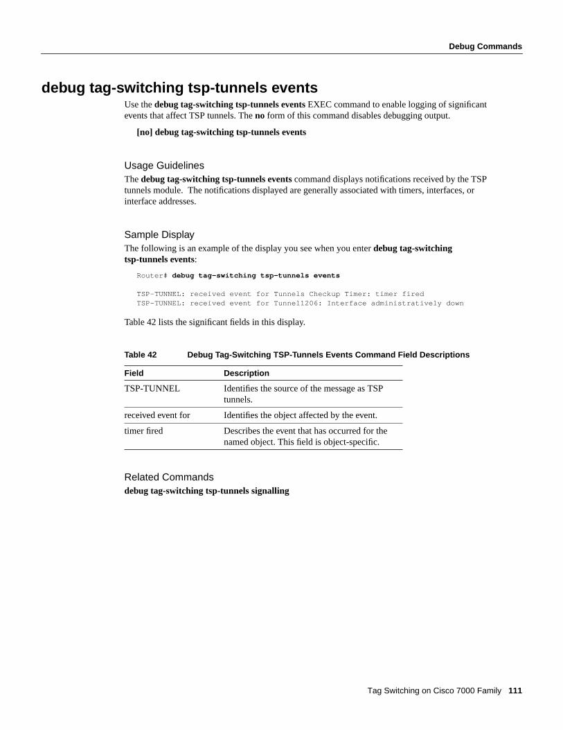
Debug Commands
Tag Switching on Cisco 7000 Family 111
debug tag-switching tsp-tunnels eventsUse thedebug tag-switching tsp-tunnels eventsEXEC command to enable logging of significantevents that affect TSP tunnels. Theno form of this command disables debugging output.
[no] debug tag-switching tsp-tunnels events
Usage GuidelinesThedebug tag-switching tsp-tunnels eventscommand displays notifications received by the TSPtunnels module. The notifications displayed are generally associated with timers, interfaces, orinterface addresses.
Sample DisplayThe following is an example of the display you see when you enterdebug tag-switchingtsp-tunnels events:
Router# debug tag-switching tsp-tunnels events
TSP-TUNNEL: received event for Tunnels Checkup Timer: timer firedTSP-TUNNEL: received event for Tunnel1206: Interface administratively down
Table 42 lists the significant fields in this display.
Table 42 Debug Tag-Switching TSP-Tunnels Events Command Field Descriptions
Related Commandsdebug tag-switching tsp-tunnels signalling
Field Description
TSP-TUNNEL Identifies the source of the message as TSPtunnels.
received event for Identifies the object affected by the event.
timer fired Describes the event that has occurred for thenamed object. This field is object-specific.

Debug Commands
112 Cisco IOS Release 11.1CT
debug tag-switching tsp-tunnels signallingUse thedebug tag-switching tsp-tunnels signalling EXEC command to enable logging of TSPtunnel signalling activity. Theno form of this command disables debugging output.
[no] debug tag-switching tsp-tunnels signalling
Usage GuidelinesTSP tunnels are signalled using the Resource Reservation Protocol (RSVP). TSP tunnelestablishment is initiated at the head-end router by making an active open request to RSVP, whichcauses a message to be sent towards the tail-end router. At the tail-end router, RSVP notifies the TSPtunnels module of the incoming open request. If the tailend router accepts the request, it makes acorresponding passive open request to RSVP, which causes a message to return to the headendrouter, establishing the TSP tunnel state at each hop along the way.
Thedebug tag-switching tsp-tunnels signallingcommand displays the signalling requests made toRSVP by the TSP tunnels modules at the headend and tail-end routers. It also displays the signallingrequests made by RSVP to the TSP tunnels modules at every hop along the path, in order to establishthe TSP tunnel state.
Sample DisplayThe following is an example of the display you see when you enterdebug tag-switchingtsp-tunnels signalling:
Router# debug tag-switching tsp-tunnels signalling
Open at tunnel head: TSP-TUNNEL-SIG: tunnel 10.106.0.6 1206: RSVP head-end openOpen at tunnel tail: TSP-TUNNEL-SIG: received NEW PATH TAIL ARRIVAL event about tunnel 10.106.0.6 1206 TSP-TUNNEL-SIG: tunnel 10.106.0.6 1206: RSVP tail-end open
TSP-TUNNEL-SIG: tunnel 10.106.0.6 1206 NEW PATH TAIL ARRIVAL event handled successfullyState setup at tail hop: TSP-TUNNEL-SIG: received ADD RESV request for tunnel 10.106.0.6 1206 TSP-TUNNEL-SIG: tunnel 10.106.0.6 1206: path previous hop is 10.2.0.10 (Et4/0/2) TSP-TUNNEL-SIG: sending ADD RESV reply for tunnel 10.106.0.6 1206State setup at intermediate hop: TSP-TUNNEL-SIG: received ADD RESV request for tunnel 10.106.0.6 1206 TSP-TUNNEL-SIG: tunnel 10.106.0.6 1206: path previous hop is 10.32.0.6 (AT1/0.1) TSP-TUNNEL-SIG: tunnel 10.106.0.6 1206: path next hop is 10.2.0.12 (Et4/0/2) TSP-TUNNEL-SIG: sending ADD RESV reply for tunnel 10.106.0.6 1206State setup at head hop: TSP-TUNNEL-SIG: received ADD RESV request for tunnel 10.106.0.6 1206 TSP-TUNNEL-SIG: tunnel 10.106.0.6 1206: path next hop is 10.32.0.10 (AT0/0.1) TSP-TUNNEL-SIG: sending ADD RESV reply for tunnel 10.106.0.6 1206
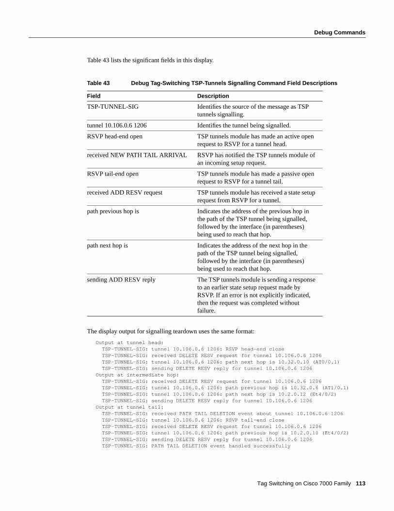
Debug Commands
Tag Switching on Cisco 7000 Family 113
Table 43 lists the significant fields in this display.
Table 43 Debug Tag-Switching TSP-Tunnels Signalling Command Field Descriptions
The display output for signalling teardown uses the same format:
Output at tunnel head: TSP-TUNNEL-SIG: tunnel 10.106.0.6 1206: RSVP head-end close TSP-TUNNEL-SIG: received DELETE RESV request for tunnel 10.106.0.6 1206 TSP-TUNNEL-SIG: tunnel 10.106.0.6 1206: path next hop is 10.32.0.10 (AT0/0.1) TSP-TUNNEL-SIG: sending DELETE RESV reply for tunnel 10.106.0.6 1206Output at intermediate hop: TSP-TUNNEL-SIG: received DELETE RESV request for tunnel 10.106.0.6 1206 TSP-TUNNEL-SIG: tunnel 10.106.0.6 1206: path previous hop is 10.32.0.6 (AT1/0.1) TSP-TUNNEL-SIG: tunnel 10.106.0.6 1206: path next hop is 10.2.0.12 (Et4/0/2) TSP-TUNNEL-SIG: sending DELETE RESV reply for tunnel 10.106.0.6 1206Output at tunnel tail: TSP-TUNNEL-SIG: received PATH TAIL DELETION event about tunnel 10.106.0.6 1206 TSP-TUNNEL-SIG: tunnel 10.106.0.6 1206: RSVP tail-end close TSP-TUNNEL-SIG: received DELETE RESV request for tunnel 10.106.0.6 1206 TSP-TUNNEL-SIG: tunnel 10.106.0.6 1206: path previous hop is 10.2.0.10 (Et4/0/2) TSP-TUNNEL-SIG: sending DELETE RESV reply for tunnel 10.106.0.6 1206 TSP-TUNNEL-SIG: PATH TAIL DELETION event handled successfully
Field Description
TSP-TUNNEL-SIG Identifies the source of the message as TSPtunnels signalling.
tunnel 10.106.0.6 1206 Identifies the tunnel being signalled.
RSVP head-end open TSP tunnels module has made an active openrequest to RSVP for a tunnel head.
received NEW PATH TAIL ARRIVAL RSVP has notified the TSP tunnels module ofan incoming setup request.
RSVP tail-end open TSP tunnels module has made a passive openrequest to RSVP for a tunnel tail.
received ADD RESV request TSP tunnels module has received a state setuprequest from RSVP for a tunnel.
path previous hop is Indicates the address of the previous hop inthe path of the TSP tunnel being signalled,followed by the interface (in parentheses)being used to reach that hop.
path next hop is Indicates the address of the next hop in thepath of the TSP tunnel being signalled,followed by the interface (in parentheses)being used to reach that hop.
sending ADD RESV reply The TSP tunnels module is sending a responseto an earlier state setup request made byRSVP. If an error is not explicitly indicated,then the request was completed withoutfailure.

Debug Commands
114 Cisco IOS Release 11.1CT
Related Commandsdebug tag-switching tsp-tunnels eventsdebug tag-switching tsp-tunnels tagging
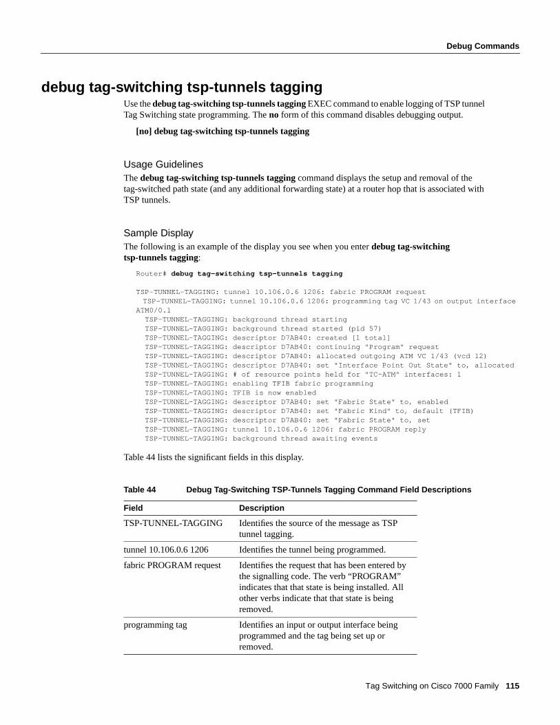
Debug Commands
Tag Switching on Cisco 7000 Family 115
debug tag-switching tsp-tunnels taggingUse thedebug tag-switching tsp-tunnels taggingEXEC command to enable logging of TSP tunnelTag Switching state programming. Theno form of this command disables debugging output.
[no] debug tag-switching tsp-tunnels tagging
Usage GuidelinesThedebug tag-switching tsp-tunnels tagging command displays the setup and removal of thetag-switched path state (and any additional forwarding state) at a router hop that is associated withTSP tunnels.
Sample DisplayThe following is an example of the display you see when you enterdebug tag-switchingtsp-tunnels tagging:
Router# debug tag-switching tsp-tunnels tagging
TSP-TUNNEL-TAGGING: tunnel 10.106.0.6 1206: fabric PROGRAM requestTSP-TUNNEL-TAGGING: tunnel 10.106.0.6 1206: programming tag VC 1/43 on output interface
ATM0/0.1 TSP-TUNNEL-TAGGING: background thread starting TSP-TUNNEL-TAGGING: background thread started (pid 57) TSP-TUNNEL-TAGGING: descriptor D7AB40: created [1 total] TSP-TUNNEL-TAGGING: descriptor D7AB40: continuing "Program" request TSP-TUNNEL-TAGGING: descriptor D7AB40: allocated outgoing ATM VC 1/43 (vcd 12) TSP-TUNNEL-TAGGING: descriptor D7AB40: set "Interface Point Out State" to, allocated TSP-TUNNEL-TAGGING: # of resource points held for "TC-ATM" interfaces: 1 TSP-TUNNEL-TAGGING: enabling TFIB fabric programming TSP-TUNNEL-TAGGING: TFIB is now enabled TSP-TUNNEL-TAGGING: descriptor D7AB40: set "Fabric State" to, enabled TSP-TUNNEL-TAGGING: descriptor D7AB40: set "Fabric Kind" to, default (TFIB) TSP-TUNNEL-TAGGING: descriptor D7AB40: set "Fabric State" to, set TSP-TUNNEL-TAGGING: tunnel 10.106.0.6 1206: fabric PROGRAM reply TSP-TUNNEL-TAGGING: background thread awaiting events
Table 44 lists the significant fields in this display.
Table 44 Debug Tag-Switching TSP-Tunnels Tagging Command Field Descriptions
Field Description
TSP-TUNNEL-TAGGING Identifies the source of the message as TSPtunnel tagging.
tunnel 10.106.0.6 1206 Identifies the tunnel being programmed.
fabric PROGRAM request Identifies the request that has been entered bythe signalling code. The verb “PROGRAM”indicates that that state is being installed. Allother verbs indicate that that state is beingremoved.
programming tag Identifies an input or output interface beingprogrammed and the tag being set up orremoved.
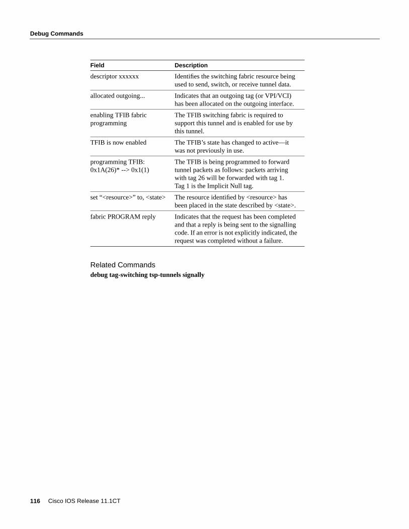
Debug Commands
116 Cisco IOS Release 11.1CT
Related Commandsdebug tag-switching tsp-tunnels signally
descriptor xxxxxx Identifies the switching fabric resource beingused to send, switch, or receive tunnel data.
allocated outgoing... Indicates that an outgoing tag (or VPI/VCI)has been allocated on the outgoing interface.
enabling TFIB fabricprogramming
The TFIB switching fabric is required tosupport this tunnel and is enabled for use bythis tunnel.
TFIB is now enabled The TFIB’s state has changed to active—itwas not previously in use.
programming TFIB:0x1A(26)* --> 0x1(1)
The TFIB is being programmed to forwardtunnel packets as follows: packets arrivingwith tag 26 will be forwarded with tag 1.Tag 1 is the Implicit Null tag.
set “<resource>” to, <state> The resource identified by <resource> hasbeen placed in the state described by <state>.
fabric PROGRAM reply Indicates that the request has been completedand that a reply is being sent to the signallingcode. If an error is not explicitly indicated, therequest was completed without a failure.
Field Description
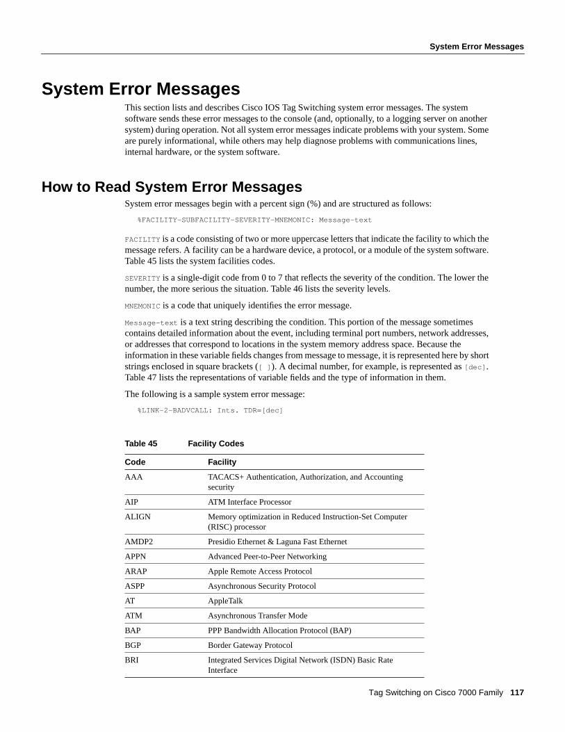
System Error Messages
Tag Switching on Cisco 7000 Family 117
System Error MessagesThis section lists and describes Cisco IOS Tag Switching system error messages. The systemsoftware sends these error messages to the console (and, optionally, to a logging server on anothersystem) during operation. Not all system error messages indicate problems with your system. Someare purely informational, while others may help diagnose problems with communications lines,internal hardware, or the system software.
How to Read System Error MessagesSystem error messages begin with a percent sign (%) and are structured as follows:
%FACILITY-SUBFACILITY-SEVERITY-MNEMONIC: Message-text
FACILITY is a code consisting of two or more uppercase letters that indicate the facility to which themessage refers. A facility can be a hardware device, a protocol, or a module of the system software.Table 45 lists the system facilities codes.
SEVERITY is a single-digit code from 0 to 7 that reflects the severity of the condition. The lower thenumber, the more serious the situation. Table 46 lists the severity levels.
MNEMONIC is a code that uniquely identifies the error message.
Message-text is a text string describing the condition. This portion of the message sometimescontains detailed information about the event, including terminal port numbers, network addresses,or addresses that correspond to locations in the system memory address space. Because theinformation in these variable fields changes from message to message, it is represented here by shortstrings enclosed in square brackets ([ ] ). A decimal number, for example, is represented as[dec] .Table 47 lists the representations of variable fields and the type of information in them.
The following is a sample system error message:
%LINK-2-BADVCALL: Ints. TDR=[dec]
Table 45 Facility Codes
Code Facility
AAA TACACS+ Authentication, Authorization, and Accountingsecurity
AIP ATM Interface Processor
ALIGN Memory optimization in Reduced Instruction-Set Computer(RISC) processor
AMDP2 Presidio Ethernet & Laguna Fast Ethernet
APPN Advanced Peer-to-Peer Networking
ARAP Apple Remote Access Protocol
ASPP Asynchronous Security Protocol
AT AppleTalk
ATM Asynchronous Transfer Mode
BAP PPP Bandwidth Allocation Protocol (BAP)
BGP Border Gateway Protocol
BRI Integrated Services Digital Network (ISDN) Basic RateInterface

System Error Messages
118 Cisco IOS Release 11.1CT
BRIMUX AS5200 BRIMUX board
BSC Binary Synchronous Communications mode
BSTUN Block serial tunneling
C1600 Cisco 1600 platform
C3600 Cisco 3600 platform
C5RSP Cisco Catalyst 5000 platform
CBUS ciscoBus controller
CDM Cable Data Modem subsystem
CI 75xx platform chassis interface
CIP facility Channel Interface Processor
CIRRUS_PM Slow speed async/sync port module
CLEAR Clear facility
CLNS OSI Connectionless Network Service
CLS Cisco Link Services
CLSDR Cisco Link Services Driver
COMP Point-to-point compression
CONTROLLER Controller
CPAD Compression service adapter
CPM Combo Port Module device driver
CSC2 CSC2/CSC3 CPU cards
CT3 Channelized T3 port adapter
DBUS Data bus
DIALER Dial-on-demand routing
DLC Data-link control
DLSw Data-link switching
DMA Direct memory access
DNET DECnet
DRP Director Response Protocol
DSPU Downstream physical unit
DSX1 Channelized E1 (Europe) and T1(US) telephony standard
DUAL Enhanced Interior Gateway Routing Protocol
DVMRP Distance Vector Multicast Routing Protocol
EGP Exterior Gateway Protocol
ENT_API Entity MIB API
ENV Environmental monitor card
ETHERNET Ethernet for the C1000 series
FDDI Fiber Distributed Data Interface
FLASH Flash nonvolatile memory
Table 45 Facility Codes (Continued)
Code Facility

System Error Messages
Tag Switching on Cisco 7000 Family 119
FR Frame Relay
FTC_TRUNK Cisco 3801 platform
GRIP Xerox Network Systems (XNS) Routing Protocol
HD HD64570 serial controller
HOOD LAN controller 100VG-AnyLAN interface
HP100VG 100VG-AnyLAN PA driver
HUB Cisco Ethernet hub
IBM2692 IBM Token Ring chip set
IFS IOS File System
IGRP Interior Gateway Routing Protocol
ILACC ILACC driver
INTERFACE_API Binary API for the interface descriptor block
IP Internet Protocol
IPC Interprocess Communication
IPFAST IP fast switching
IPRT Internet Protocol routing
IPX Internetwork Packet Exchange Protocol
IP-SNMP Simple Network Management Protocol specific to IP
ISDN Integrated Services Digital Network
LANCE Local Area Network Controller Ethernet
LANE LAN Emulation
LANMGR IBM LAN Network Manager
LAPB X.25 Link Access Procedure, Balanced
LAT DEC Local Area Transport
LEX LAN extension
LINEPROTO Line Protocol
LINK Data link
LLC2 Logical Link Control type 2
LLIST Linked list facility
LNMC LAN network manager
LPD Line printer daemon
MAILBOX ChipCom mailbox support
MBRI Multi-BRI port module
MCI Multiport Communications Interface
MK5 MK5025 serial controller
MPA68360 VIP Multi-channel Port Adapter
MROUTE Multicast route
MUESLIX Mx serial application-specific integrated circuit (ASIC)
Table 45 Facility Codes (Continued)
Code Facility
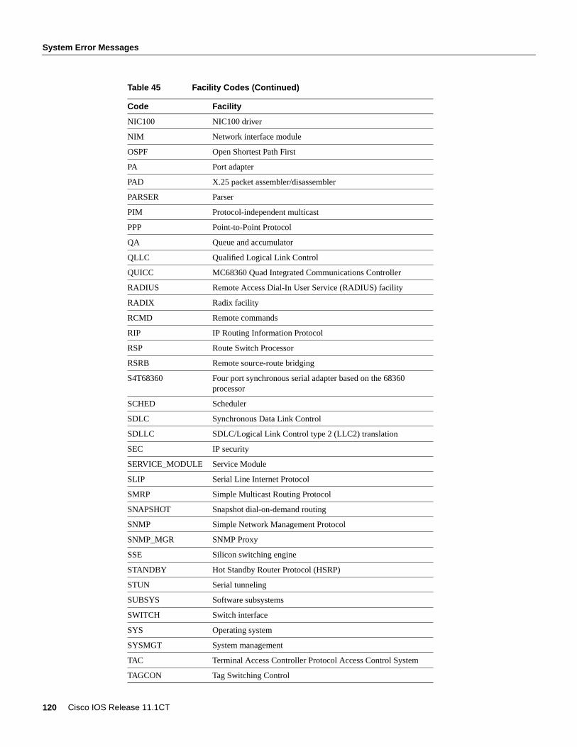
System Error Messages
120 Cisco IOS Release 11.1CT
NIC100 NIC100 driver
NIM Network interface module
OSPF Open Shortest Path First
PA Port adapter
PAD X.25 packet assembler/disassembler
PARSER Parser
PIM Protocol-independent multicast
PPP Point-to-Point Protocol
QA Queue and accumulator
QLLC Qualified Logical Link Control
QUICC MC68360 Quad Integrated Communications Controller
RADIUS Remote Access Dial-In User Service (RADIUS) facility
RADIX Radix facility
RCMD Remote commands
RIP IP Routing Information Protocol
RSP Route Switch Processor
RSRB Remote source-route bridging
S4T68360 Four port synchronous serial adapter based on the 68360processor
SCHED Scheduler
SDLC Synchronous Data Link Control
SDLLC SDLC/Logical Link Control type 2 (LLC2) translation
SEC IP security
SERVICE_MODULE Service Module
SLIP Serial Line Internet Protocol
SMRP Simple Multicast Routing Protocol
SNAPSHOT Snapshot dial-on-demand routing
SNMP Simple Network Management Protocol
SNMP_MGR SNMP Proxy
SSE Silicon switching engine
STANDBY Hot Standby Router Protocol (HSRP)
STUN Serial tunneling
SUBSYS Software subsystems
SWITCH Switch interface
SYS Operating system
SYSMGT System management
TAC Terminal Access Controller Protocol Access Control System
TAGCON Tag Switching Control
Table 45 Facility Codes (Continued)
Code Facility
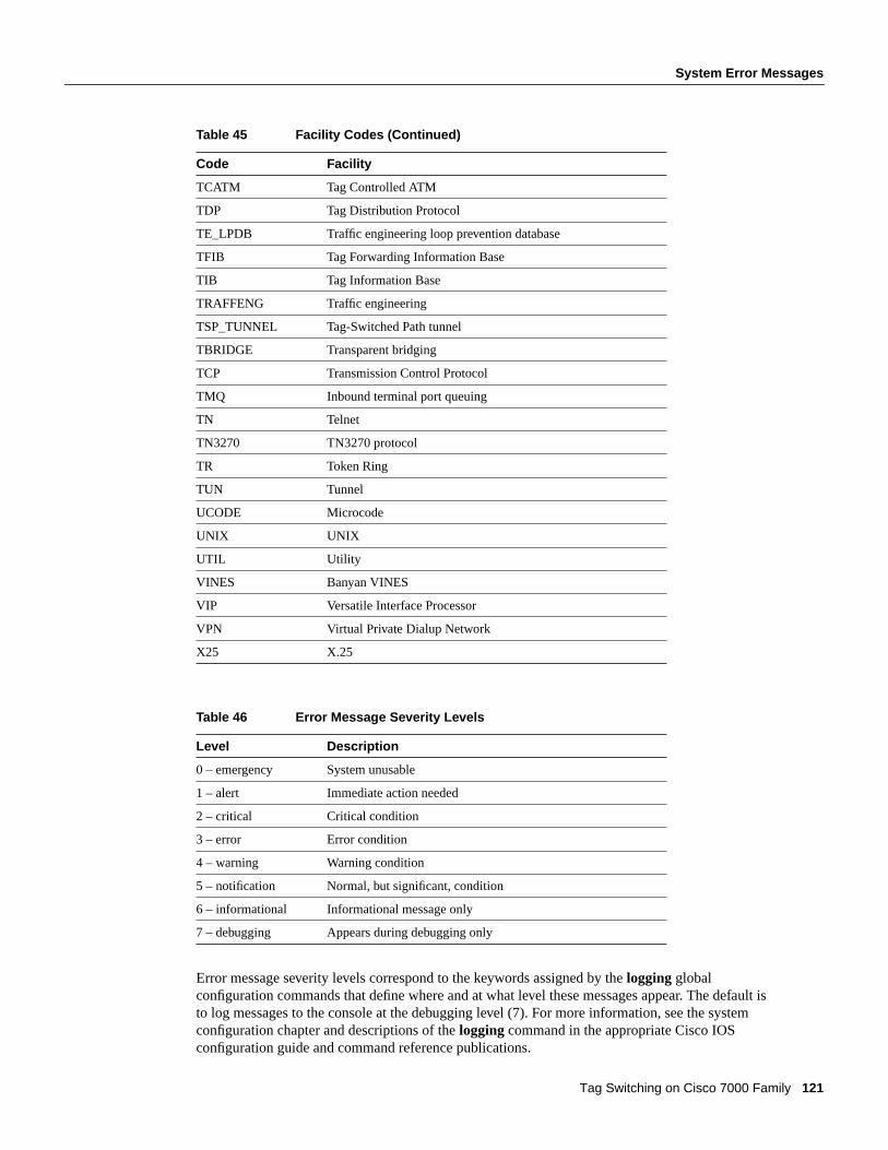
System Error Messages
Tag Switching on Cisco 7000 Family 121
Error message severity levels correspond to the keywords assigned by thelogging globalconfiguration commands that define where and at what level these messages appear. The default isto log messages to the console at the debugging level (7). For more information, see the systemconfiguration chapter and descriptions of thelogging command in the appropriate Cisco IOSconfiguration guide and command reference publications.
TCATM Tag Controlled ATM
TDP Tag Distribution Protocol
TE_LPDB Traffic engineering loop prevention database
TFIB Tag Forwarding Information Base
TIB Tag Information Base
TRAFFENG Traffic engineering
TSP_TUNNEL Tag-Switched Path tunnel
TBRIDGE Transparent bridging
TCP Transmission Control Protocol
TMQ Inbound terminal port queuing
TN Telnet
TN3270 TN3270 protocol
TR Token Ring
TUN Tunnel
UCODE Microcode
UNIX UNIX
UTIL Utility
VINES Banyan VINES
VIP Versatile Interface Processor
VPN Virtual Private Dialup Network
X25 X.25
Table 46 Error Message Severity Levels
Level Description
0 – emergency System unusable
1 – alert Immediate action needed
2 – critical Critical condition
3 – error Error condition
4 – warning Warning condition
5 – notification Normal, but significant, condition
6 – informational Informational message only
7 – debugging Appears during debugging only
Table 45 Facility Codes (Continued)
Code Facility

System Error Messages
122 Cisco IOS Release 11.1CT
Table 47 Representation of Variable Fields in Error Messages
Error Message Traceback ReportsSome messages describe internal errors and contain traceback information. This information is veryimportant and should be included when you report a problem to your technical supportrepresentative.
The following sample message includes traceback information:
-Process= ”Exec”, level= 0, pid= 17-Traceback= 1A82 1AB4 6378 A072 1054 1860
Tag Switching Error MessagesThis section lists the Tag Switching error messages.
Error Message%LLIST-3-OFFLIST: [chars] from 0x[hex], 0x[hex] not on list
Explanation An internal inconsistency was detected when an attempt was made to remove from alist an item not on the list.
Recommended Action Copy the message exactly as it appears, and report it to your technicalsupport representative.
Error Message%LLIST-3-ONLIST: [chars] to 0x[hex], 0x[hex] on list
Explanation An internal inconsistency was detected when an attempt was made to add to a list anitem already on the list.
Recommended Action Copy the message exactly as it appears, and report it to your technicalsupport representative.
Representation Type of Information
[atalk_address] AppleTalk address
[atalk_net] AppleTalk network, either 600 or 600-601
[char] Single character
[chars] Character string
[dec] Decimal number
[enet] Ethernet address (for example, 0000.FEED.00C0)
[hex] Hexadecimal number
[inet] Internet address (for example, 12.128.2.16)
[int] Integer number
[node] Address or node name
[sci_notation] Scientific notation
[t-line] Terminal line number in octal (or decimal if thedecimal-TTY service is enabled)
[v-name] VINES name; or number (hex or decimal)

System Error Messages
Tag Switching on Cisco 7000 Family 123
Error Message%TAGCON-3-ALLOC: Cannot alloc [chars]
Explanation An attempt to allocate a tag-switching data structure failed because of a low memorycondition.
Recommended Action Reduce other system activity if possible. If this message persists, call yourtechnical support representative for assistance.
Error Message%TAGCON-3-BUFFERBIND: unexpected error [dec]; peer [chars]; [chars]
Explanation An unexpected failure occurred during the building of a TDP protocol informationelement (PIE) for transmission to a TDP peer device. It occurred when an attempt was made to adda tag binding or an address to the PIE.
Recommended Action Copy the message exactly as it appears, and report it to your technicalsupport representative.
Error Message%TAGCON-3-CONSISTENCY: [chars]
Explanation An action attempted by the tag control process encountered an unexpected condition.
Recommended Action Copy the message exactly as it appears, and report it to your technicalsupport representative.
Error Message%TAGCON-3-DEADADJ: [inet]/[int], [chars]
Explanation A problem was encountered in the cleanup following termination of a TDP session.
Recommended Action Copy the message exactly as it appears, and report it to your technicalsupport representative.
Error Message%TAGCON-3-DEFCASE_BINDING_PIE: Unexpected blist_type ([dec]) for [chars]PIE from peer [chars]
Explanation A TDP PIE that was received from a TDP peer device contained an unexpectedbinding list type. The PIE will be ignored.
Recommended Action This is an informational message. The system ignores the PIE. This mayresult in impaired or faulty Tag Switching with the peer device. You might be able to correct thesituation by the disabling of dynamic Tag Switching at the chassis level (enter theno tag ipcommand), waiting 15 to 20 seconds, and then reenabling it (enter thetag-switching ip command).Copy the message exactly as it appears, and report it to your technical support representative.
Error Message%TAGCON-3-DIRADJTREE: [inet]/[int]; [chars]
Explanation An operation on the TDP directed adjacency data structure failed.
Recommended Action Copy the message exactly as it appears, and report it to your technicalsupport representative.
System Error Messages
124 Cisco IOS Release 11.1CT
Error Message%TAGCON-3-EVENTQ: Can’t alloc work item for [chars]
Explanation When a process, such as the TDP process, must request that the tag distribution andcontrol process take some action, it queues a work item for the tag distribution and control process.If the attempt to queue the work item fails, the message shown here is generated. The failure canoccur if the system is unable to allocate memory to hold the work request, or if the process hasstopped accepting requests on its work queue.
Recommended Action Copy the message exactly as it appears, and report it to your technicalsupport representative.
Error Message%TAGCON-3-INIT: process cannot initialize
Explanation The tag distribution and control process failed to initialize itself. The probable causeis insufficient memory.
Recommended Action Reduce other system activity if possible. If this message persists, call yourtechnical support representative for assistance.
Error Message%TAGCON-3-LATREVNUMWRAP: Tag Local Address Table revision number wrapped
Explanation The revision number used to manage advertisement of interface addresses to TDPpeer devices overflowed. This results in faulty advertisement of interface addresses to TDP peerdevices and faulty Tag Switching on those peer devices.
Recommended Action To restore proper interface address advertisement, reboot the platform.Report this condition to your technical support representative.
Error Message%TAGCON-3-NOTIMPL: peer [chars]; [chars] not implemented
Explanation A TDP peer device has requested an action that is not currently implemented by thetag distribution and control subsystem.
Recommended Action The request is ignored. If it occurs repeatedly, copy the message exactly asit appears, and report it to your technical support representative.
Error Message%TAGCON-3-PEERSM: TDP peer [int]([chars]): [chars]
Explanation An operation involving the state machine for a TDP peer device failed.
Recommended Action Copy the message exactly as it appears, and report it to your technicalsupport representative.
Error Message%TAGCON-3-PROCESS: process not created
Explanation An attempt to create the tag distribution and control process failed. The probablecause is insufficient memory.
Recommended Action Reduce other system activity, if possible. If this message persists, call yourtechnical support representative for assistance.

System Error Messages
Tag Switching on Cisco 7000 Family 125
Error Message%TAGCON-3-RADIXTREE: TIB walk failed ([chars])
Explanation Some Tag Information Base (TIB) maintenance operations involve a complete scan(walk) of the TIB data structure. This message is generated when a TIB walk encounters anunexpected failure.
Recommended Action Copy the message exactly as it appears, and report it to your technicalsupport representative.
Error Message%TAGCON-3-REGISTRY: Unexpected [chars] for reg_invoke_[chars]
Recommended Action If the message recurs, copy the error message exactly as it appears on theconsole or in the system log, call your Cisco technical support representative, and provide therepresentative with the error message text.
Error Message%TAGCON-3-SM: Unexpected event; state=[chars], event=[chars]
Explanation An operation on the state machine for the tag distribution and control process failed.
Recommended Action Copy the message exactly as it appears, and report it to your technicalsupport representative.
Error Message%TAGCON-3-TDPID: peer [chars], TDP Id/Addr mapping problem ([chars])
Explanation The tag distribution and control process maintains a data structure used to convertbetween the TDP identifier for a TDP peer device and the IP addresses of that peer device. Thismessage is generated when an internal inconsistency is discovered in that data structure.
Recommended Action Disable dynamic Tag Switching at the chassis level (enter thenotag-switching ip command), wait 15 to 20 seconds, and then reenable it (enter thetag-switching ipcommand). In addition, copy the message exactly as it appears, and report it to your technicalsupport representative.
Error Message%TAGCON-3-TDPID_ADDR_TBL: [chars] sort bad; item [dec]
Explanation The tag distribution and control process maintains a data structure used to convertbetween the TDP identifier for a TDP peer device and the IP addresses of that peer device. Thismessage is generated when an internal inconsistency is discovered in that data structure.
Recommended Action Disable dynamic Tag Switching at the chassis level (enter thenotag-switching ip command), wait 15 to 20 seconds, and then reenable it (enter thetag-switching ipcommand). In addition, copy the message exactly as it appears, and report it to your technicalsupport representative.

System Error Messages
126 Cisco IOS Release 11.1CT
Error Message%TAGCON-4-ADDRQ: Can’t alloc work item for [int]
Explanation When a new IP address for a TDP peer device is learned, it may be necessary toupdate the Tag Forwarding Information Base (TFIB) for any routes for which the new address is anext hop. Deciding whether it is necessary to update the TFIB is the responsibility of an "addressprocess." This message is generated when an attempt to queue work for the address process fails.
Recommended Action This is an informational message. The system remembers that it needs todo this work and regularly attempts to queue the necessary work item. If this message occursrepeatedly, copy it exactly as it appears, and report it to your technical support representative.
Error Message%TAGCON-4-ADDR_PROC: Can’t create tagcon addr proc
Explanation When a new IP address for a TDP peer device is learned, it may be necessary toupdate the TFIB for any routes for which the new address is a next hop. Deciding whether it isnecessary to update the TFIB is the responsibility of an "address process". This message is generatedwhen an attempt to create the address process fails.
Recommended Action This is an informational message. As long as it needs the process, thesystem regularly attempts to create it. If this message occurs repeatedly, copy it exactly as it appears,and report it to your technical support representative.
Error Message%TAGCON-4-INIT_TAG_ALLOC: Failure to initialize tag allocation pool [dec]
Explanation The system was unable to initialize the data structure used to support allocation oftags for Tag Switching for the specified tag pool.
Recommended Action The system ignores the event. However, because the system will not beable to allocate tags from the tag pool, it will not advertise them to peer devices. Therefore, it willnot be able to forward tagged packets it receives (because it advertises no tags, it should not receiveany tagged packets). Copy the message exactly as it appears, and report it along with the startup andrunning configuration to your technical support representative.
Error Message%TAGCON-5-SEND: cannot queue TDP [chars] pie for [int]([chars])
Explanation An attempt to queue a TDP PIE for transmission to a TDP peer device failed.
Recommended Action This is an informational message. Failure to queue a PIE for a peer deviceshould occur only when the TDP session with the peer device no longer exists. The software shouldrecover from this situation by discarding the TDP session and trying to establish a new one. If thismessage occurs repeatedly, copy it exactly as it appears, and report it to your technical supportrepresentative.
Error Message%TCATM-3-BADINSERT: [inet]/[int] x[hex] to 0x[hex]
Explanation An internal inconsistency was detected when an attempt was made to insert an itemin a list.
Recommended Action Copy the message exactly as it appears, and report it to your technicalsupport representative.
System Error Messages
Tag Switching on Cisco 7000 Family 127
Error Message%TCATM-3-BADSTATE: [inet]/[int] [chars] [chars]->[chars]
Recommended Action ATM TAG Control uses a table-driven state machine to keep track andtransition a TVC through various states. A state transition occurs when a TVC receives one of manypossible events. When this error occurs, it means that a TVC receives an event that it did not expectwhile in this state.
Recommended Action The system can continue, but may lose the TVC that generates this error.Copy the message exactly as it appears, and report it to your technical support representative.
Error Message%TCATM-3-NOTRUNNING: ATM-TAGCONTROL is not running
Explanation An attempt to request or to create a binding failed while the ATM tag-control systemwas not initialized. Probable cause is misconfiguration or low memory.
Recommended Action Reduce other system activity if possible, and call your technical supportrepresentative for assistance.
Error Message%TCATM-3-OFFLIST: [inet]/[int] 0x[hex] not on list 0x[hex]
Explanation An internal inconsistency was detected when an attempt was made to remove from alist an item not on the list.
Recommended Action Copy the message exactly as it appears, and report it to your technicalsupport representative.
Error Message%TCATM-3-ONLIST: [inet]/[int] 0x[hex] on list 0x[hex]
Explanation An internal inconsistency was detected when an attempt was made to add to a list anitem already on the list.
Recommended Action Copy the message exactly as it appears, and report it to your technicalsupport representative.
Error Message%TCATM-3-PROCESS: process not created
Explanation An attempt to create the ATM tag control process failed. The probable cause isinsufficient memory.
Recommended Action Reduce other system activity if possible, and call your technical supportrepresentative for assistance.

System Error Messages
128 Cisco IOS Release 11.1CT
Error Message%TCATM-3-UNEXPECTEDBIND: Interface [chars] received unexpected bind for[int]%m
Explanation An unexpected bind is received for a prefix. This message appears only when amemory resource allocation failure prevents this peer device from asking the neighbor to release thebind. The system will continue, but the downstream neighbor could be holding a binding for whichthere is no matching VCI at this end.
Recommended Action Reduce other system activity if possible, and call your technical supportrepresentative for assistance.
Error Message%TCATM-4-HOP_EXCEEDED: Hop Count exceeded for [int]%m on [chars]
Explanation This message appears when a loop is discovered in the network.
Recommended Action Check the configuration and network path for the relevant prefix.
Error Message%TCATM-4-MALFORMED_PIE: Interface [chars] malformed TDP PIE
Explanation ATM TAG Control received a malformed PIE from TDP.
Recommended Action This does not affect system operation, but if the error persists, report it toyour technical support representative.
Error Message%TCATM-4-NOTAGIP: Tag switching disabled on [chars]
Explanation Tag Switching is not enabled on the specified interface. Tag VCI requests andadvertising will be rejected. As a side effect, the VCI requests at the upstream device can remain inBindWait state until Tag Switching is reenabled on this interface.
Error Message%TCATM-4-ROUTING_LOOP: Possible routing loop [int]%m on [chars]
Explanation This message appears when a loop is discovered in the network.
Recommended Action Check the configuration and network path for the relevant prefix.
Error Message%TDP-3-BAD_ADDRESS_LEN: peer [chars]; address len [dec]
Explanation A TDP PIE containing an address with a bad length has been received from a peerdevice.
Recommended Action This is an informational message. The system ignores the remainder of thePIE beyond the bad item. The partially processed PIE may result in impaired or faulty Tag Switchingwith the peer device. You might be able to correct the situation by disabling dynamic Tag Switchingat the chassis level (enter theno tag-switching ipcommand), waiting 15 to 20 seconds, and thenreenabling it (enter thetag-switching ip command). In addition, copy the message exactly as itappears, and report it to your technical support representative.
System Error Messages
Tag Switching on Cisco 7000 Family 129
Error Message%TDP-3-BAD_METRIC_LEN: peer [chars]; metric len [dec]
Explanation A TDP PIE containing a metric with a bad length has been received from a peerdevice.
Recommended Action This is an informational message. The system ignores the remainder of thePIE beyond the bad item. The partially processed PIE may result in impaired or faulty Tag Switchingwith the peer device. You might be able to correct the situation by disabling dynamic Tag Switchingat the chassis level (enter theno tag-switching ipcommand), waiting 15 to 20 seconds, and thenreenabling it (enter thetag-switching ip command). In addition, copy the message exactly as itappears, and report it to your technical support representative.
Error Message%TDP-3-BAD_MLIST_TYPE: peer [chars]; mlist_type [dec]; [chars] pie
Explanation A TDP PIE containing an unknown metric list type or one that is unexpected for thesituation has been received from a peer device.
Recommended Action This is an informational message. The system ignores the PIE. This mayresult in impaired or faulty Tag Switching with the peer device. You might be able to correct thesituation by disabling dynamic Tag Switching at the chassis level (enter theno tag-switching ipcommand), waiting 15 to 20 seconds, and then reenabling it (enter thetag-switching ip command).In addition, copy the message exactly as it appears, and report it to your technical supportrepresentative.
Error Message%TDP-3-BAD_PIE: peer [chars]; unknown pie type 0x[hex]
Explanation An unknown TDP PIE type has been received from a peer device.
Recommended Action This is an informational message. The system ignores the PIE. This mayresult in impaired or faulty Tag Switching with the peer device. You might be able to correct thesituation by disabling dynamic Tag Switching at the chassis level (enter theno tag-switching ipcommand), waiting 15 to 20 seconds, and then reenabling it (enter theno tag-switching ipcommand). In addition, copy the message exactly as it appears, and report it to your technicalsupport representative.
Error Message%TDP-3-BAD_PREFIX_LEN: peer [chars]; prefix len [dec]
Explanation A TDP PIE containing a destination prefix with a bad length has been received froma peer device.
Recommended Action This is an informational message. The system ignores the remainder of thePIE beyond the bad item. The partially processed PIE may result in impaired or faulty Tag Switchingwith the peer device. You might be able to correct the situation by disabling dynamic Tag Switchingat the chassis level (enter theno tag-switching ipcommand), waiting 15 to 20 seconds, and thenreenabling it (enter thetag-switching ip command). In addition, copy the message exactly as itappears, and report it to your technical support representative.
Error Message%TDP-3-CONSISTENCY: [chars]
Explanation An action attempted by the TDP encountered an unexpected condition.
Recommended Action Copy the message exactly as it appears, and report it to your technicalsupport representative.

System Error Messages
130 Cisco IOS Release 11.1CT
Error Message%TDP-3-GENERAL: [chars]
Explanation An action attempted by the TDP implementation failed.
Recommended Action Copy the message exactly as it appears, and report it to your technicalsupport representative.
Error Message%TDP-3-KA_NOMEMORY: Can’t alloc KA PIE
Explanation An attempt to allocate a buffer for a TDP Keep Alive PIE has failed.
Recommended Action The system omits transmission of the TDP keep alive PIE. This may resultin termination of one or more TDP sessions as the peer devices time out the sessions. If this messagepersists, reduce other system activity if possible, and call your technical support representative forassistance.
Error Message%TDP-3-MALFORMED_PIE: peer [chars]; format error for pie type 0x[hex]
Explanation A malformed TDP PIE has been received from a TDP peer device.
Recommended Action This is an informational message. The system recovers from this situationby terminating the TDP session and attempting to establish a new session with the peer device. Ifthis message occurs repeatedly, copy it exactly as it appears, and report it to your technical supportrepresentative.
Error Message%TDP-3-PTCLREAD: peer [chars], read failure
Explanation An error occurred while attempting to read a TDP PDU received from a peer device.
Recommended Action This is an informational message. The system recovers from this situationby terminating the TDP session and attempting to establish a new session with the peer device. Ifthis message occurs repeatedly, copy it exactly as it appears, and report it to your technical supportrepresentative.
Error Message%TDP-3-SM: unexpected event: peer [int]([chars]), state=[chars],event=[chars][chars]
Explanation An operation on the state machine for a TDP peer device failed.
Recommended Action Copy the message exactly as it appears, and report it to your technicalsupport representative.
Error Message%TDP-3-TAGATM_BAD_RANGE: Interface [chars], Bad VPI range. Can’t start aTDP session
Explanation The VPI range exchanged between the TDP peer devices is nonoverlapping.
Recommended Action The system cannot create a TDP session between the affected TDP peerdevices. Reissue thetag-switching vpi command on the appropriate interface with the correct VPIrange.
System Error Messages
Tag Switching on Cisco 7000 Family 131
Error Message%TDP-3-TAGATM_NOMEM: Interface [chars], Resource failure. Can’t start a TDPsession
Explanation An attempt to allocate a buffer for TDP TAGATM VPI/VCI ranges has failed.
Recommended Action The system cannot create a TDP session between the affected TDP peerdevices. If this message persists, reduce other system activity if possible, and call your technicalsupport representative for assistance.
Error Message%TDP-3-UNEXPECTED_ALIST_TYPE: peer [chars]; alist_type [dec]; [chars] pie
Explanation A TDP PIE containing an address list type that is unexpected for the situation hasbeen received from a peer device.
Recommended Action This is an informational message. The system ignores the PIE. This mayresult in impaired or faulty Tag Switching with the peer device. You might be able to correct thesituation by disabling dynamic Tag Switching at the chassis level (enter theno tag-switching ipcommand), waiting 15 to 20 seconds, and then reenabling it (enter theno tag-switching ipcommand). In addition, copy the message exactly as it appears, and report it to your technicalsupport representative.
Error Message%TDP-3-UNEXPECTED_BLIST_TYPE: peer [chars]; blist_type [dec]; [chars] pie
Explanation A TDP PIE containing a binding list type that is unexpected for the situation has beenreceived from a peer device.
Recommended Action This is an informational message. The system ignores the PIE. This mayresult in impaired or faulty Tag Switching with the peer device. You might be able to correct thesituation by disabling dynamic Tag Switching at the chassis level (enter theno tag-switching ipcommand), waiting 15 to 20 seconds, and then reenabling it (enter theno tag-switching ipcommand). In addition, copy the message exactly as it appears, and report it to your technicalsupport representative.
Error Message%TDP-3-UNEXPECTED_PIE: peer [chars]; unexpected pie type 0x[hex]
Explanation A TDP PIE that is unexpected for the situation has been received from a peer device.
Recommended Action This is an informational message. The system ignores the PIE. This mayresult in impaired or faulty Tag Switching with the peer device. You might be able to correct thesituation by disabling dynamic Tag Switching at the chassis level (enter theno tag-switching ipcommand), waiting 15 to 20 seconds, and then reenabling it (enter thetag-switching ip command).In addition, copy the message exactly as it appears, and report it to your technical supportrepresentative.
Error Message%TDP-3-UNKNOWN_ALIST_TYPE: peer [chars]; alist_type [dec]; [chars] pie
Explanation A TDP PIE containing an unknown address list type has been received from a peerdevice.
Recommended Action This is an informational message. The system ignores the PIE. This mayresult in impaired or faulty Tag Switching with the peer device. You might be able to correct thesituation by disabling dynamic Tag Switching at the chassis level (enter theno tag-switching ip

System Error Messages
132 Cisco IOS Release 11.1CT
command), waiting 15 to 20 seconds, and then reenabling it (enter thetag-switching ip command).In addition, copy the message exactly as it appears, and report it to your technical supportrepresentative.
Error Message%TDP-3-UNKNOWN_BLIST_TYPE: peer [chars]; blist_type [dec]; [chars] pie
Explanation A TDP PIE containing an unknown binding list type has been received from a peerdevice.
Recommended Action This is an informational message. The system ignores the PIE. This mayresult in impaired or faulty Tag Switching with the peer device. You might be able to correct thesituation by disabling dynamic Tag Switching at the chassis level (enter theno tag-switching ipcommand), waiting 15 to 20 seconds, and then reenabling it (enter thetag-switching ip command).In addition, copy the message exactly as it appears, and report it to your technical supportrepresentative.
Error Message%TDP-4-IDENT: cannot set chassis TDP ident
Explanation The TDP requires that each chassis have a TDP identifier. An attempt to set the TDPidentifier for the chassis has failed.
Recommended Action This is an informational message. As long as it needs to set its chassis TDPidentifier, the system periodically attempts to do so until it succeeds. If this message occursrepeatedly, copy it exactly as it appears, and report it to your technical support representative.
Error Message%TDP-4-PTCL: peer [chars], [chars]
Explanation A violation of the TDP protocol by a TDP peer device has been detected.
Recommended Action This is an informational message. The system recovers from this situationby terminating the TDP session and attempting to establish a new session with the peer device. Ifthis message occurs repeatedly, copy it exactly as it appears, and report it to your technical supportrepresentative.
Error Message%TDP-5-ACL: tag advertise-tags has no effect for tc-atm
Recommended Action Thetag-switching advertise-tags configuration command has no effectfor tag-controlled ATM interfaces. The rationale for this behavior is summed up this way:
• The purpose oftag-switching advertise-tagsis to restrict the set of tags that are advertised andthereby restrict the number of packets that are tagged. The command causes some packets thatmight otherwise be tagged to be sent untagged over tag-enabled interfaces.
• Because untagged packets typically cannot be forwarded at acceptable performance levels by thedevices (ATM switches) within the cloud, the access controls configured bytag-switchingadvertise-tagsare not supported for tag-controlled ATM interfaces.
Recommended Action No action is required.

System Error Messages
Tag Switching on Cisco 7000 Family 133
Error Message%TDP-5-ACL1: tag advertise-tags has no effect for tc-atm
Recommended Action Thetag-switching advertise-tags configuration command has no effectfor tag-controlled ATM interfaces. The rationale for this behavior is summed up this way:
• The purpose oftag-switching advertise-tagsis to restrict the set of tags that are advertised andthereby restrict the number of packets that are tagged. The command causes some packets thatmight otherwise be tagged to be sent untagged over tag-enabled interfaces.
• Because untagged packets typically cannot be forwarded at acceptable performance levels by thedevices (ATM switches) within the cloud, the access controls configured bytag-switchingadvertise-tagsare not supported for tag-controlled ATM interfaces.
Recommended Action No action is required.
Error Message%TDP-5-INFO: [chars]
Explanation This is an informational message generated by the TDP implementation.
Recommended Action No action is required.
Error Message %TE_LPDB-3-BUFFERMETRIC: unexpected error [dec]
Explanation An unexpected failure occurred during the building of a TDP PIE for transmission toa TDP peer device. It occurred during an attempt to add a metric to the PIE.
Recommended Action Copy the message exactly as it appears, and report it to your technicalsupport representative.
Error Message%TE_LPDB-3-CONSISTENCY: [chars]
Explanation An action attempted by the traffic engineering loop prevention implementationencountered an unexpected condition.
Recommended Action Copy the message exactly as it appears, and report it to your technicalsupport representative.
Error Message%TE_LPDB-3-INIT: uninitialized
Explanation The loop prevention database failed to initialize itself. The probable cause isinsufficient memory.
Recommended Action Reduce other system activity if possible. If this message persists, call yourtechnical support representative for assistance.
System Error Messages
134 Cisco IOS Release 11.1CT
Error Message%TE_LPDB-3-NOMEMORY: [chars]
Explanation An attempt to queue a TDP PIE for transmission to a TDP peer device failed.
Recommended Action This is an informational message. Failure to queue a PIE for a peer deviceshould occur only when the TDP session with the peer device no longer exists. The software shouldrecover from this situation by discarding the TDP session and trying to establish a new one. If thismessage occurs repeatedly, copy it exactly as it appears, and report it to your technical supportrepresentative.
Error Message%TE_LPDB-3-PROCESS: no such process
Explanation The loop prevention control process failed to initialize itself. The probable cause isinsufficient memory.
Recommended Action Reduce other system activity, if possible. If this message persists, call yourtechnical support representative for assistance.
Error Message%TE_LPDB-3-RADIXTREE: [int]/[int]; [chars]
Explanation An operation on the traffic engineering metric database failed.
Recommended Action Copy the message exactly as it appears, and report it to your technicalsupport representative.
Error Message%TE_LPDB-3-SEND: cannot queue TDP output for ([chars])
Error Message%TFIB-2-BADENCAPLEN: Invalid encaps length [dec], tag size [dec]
Recommended Action This is an informational message. The system omits the tag operation.This may result in impaired or faulty behavior for tagged packets for this destination. Copy themessage exactly as it appears, and report it to your technical support representative.
Error Message%TFIB-2-MEMORY: No memory for [chars]
Explanation An operation on the Tag Forwarding Information Base (TFIB) requiring memoryfailed because of insufficient free memory.
Recommended Action Reduce other system activity if possible. If this message persists, call yourtechnical support representative for assistance.
Error Message%TFIB-7-INVALIDINDEX: Temporary path count difference for [inet]/[int],tfib entry [dec],loadinfo has [dec],fib has [dec]
Explanation A temporary difference occurred between the Cisco Express Forwarding (CEF) database and the TFIB. This difference will be resolved later.
Recommended Action Copy the message exactly as it appears, and report it to your technicalsupport representative.
System Error Messages
Tag Switching on Cisco 7000 Family 135
Error Message%TFIB-7-INVALIDTAG: Invalid tag [chars] [chars]
Explanation An invalid tag was seen during an operation on the TFIB.
Recommended Action This is an informational message. The system omits the tag operation.This may result in impaired or faulty behavior for tagged packets for this destination. Copy themessage exactly as it appears, and report it to your technical support representative.
Error Message%TFIB-7-NONDB: Null ndb value passed to TFIB [chars]
Explanation An unexpected operation on the TFIB occurred.
Recommended Action Copy the message exactly as it appears, and report it to your technicalsupport representative.
Error Message%TFIB-7-NOPATH: No fib_path at index [dec] for [inet]/[int]
Explanation An unexpected operation on the TFIB occurred.
Recommended Action Copy the message exactly as it appears, and report it to your technicalsupport representative.
Error Message%TFIB-7-NULLFIB: Programming error: NULL fib or fibidb pointer passed totfib code
Explanation An unexpected operation on the TFIB occurred.
Recommended Action This is an informational message. The system omits the tag operation.This may result in impaired or faulty behavior for tagged packets for this destination. Copy themessage exactly as it appears, and report it to your technical support representative.
Error Message%TFIB-7-NULLPATH: NULL fib path value passed to TFIB
Explanation An unexpected operation on the TFIB occurred.
Recommended Action This is an informational message. The system omits the tag operation.This may result in impaired or faulty behavior for tagged packets for this destination. Copy themessage exactly as it appears, and report it to your technical support representative.
Error Message%TFIB-7-NULLREWRITE: NULL tag rewrite pointer value passed to TFIB fordeletion
Explanation An unexpected operation on the TFIB occurred.
Recommended Action This is an informational message. The system omits the tag operation.This may result in impaired or faulty behavior for tagged packets for this destination. Copy themessage exactly as it appears, and report it to your technical support representative.
System Error Messages
136 Cisco IOS Release 11.1CT
Error Message%TFIB-7-RESOLUTION: Temporarily unable to resolve TFIB loadinfo entry [dec]for [inet]/[int], fib has [dec] paths
Explanation A temporary difference occurred between the CEF data base and the TFIB. Thisdifference will be resolved later.
Recommended Action Copy the message exactly as it appears, and report it to your technicalsupport representative.
Error Message%TFIB-7-SPECIALIDB: TFIB attempt to resolve entry with [chars] fibidb andincoming tag [chars]
Explanation An unexpected operation on the TFIB occurred.
Recommended Action Copy the message exactly as it appears, and report it to your technicalsupport representative.
Error Message%TIB-3-GENERAL: [chars]
Explanation An action attempted by the TIB implementation failed.
Recommended Action Copy the message exactly as it appears, and report it to your technicalsupport representative.
Error Message%TIB-3-INIT: Cannot allocate TIB
Explanation During initialization for Tag Switching, an attempt to initialize the TIB failed,probably because of insufficient memory.
Recommended Action Copy the message exactly as it appears, and report it to your technicalsupport representative.
Error Message%TIB-3-LCLTAG: [inet]/[int], [chars]; unexpected tag state=[dec]
Explanation An operation on the TIB involving a locally assigned (incoming) tag failed.
Recommended Action This is an informational message. The system omits the tag operation.This may result in impaired or faulty behavior for tagged packets for this destination. Copy themessage exactly as it appears, and report it to your technical support representative.
Error Message%TIB-3-LCLTAG_ALLOC: Cannot allocate local tag for [inet]/[int]
Explanation An attempt to allocate a local (incoming) tag failed. This should happen only if thesystem has allocated all available local tags.
Recommended Action You can change the number of tags available for allocation by thetag-switching tag-range configuration command. Consult with your technical supportrepresentative to determine whether you should use this command to increase the number ofavailable tags.

System Error Messages
Tag Switching on Cisco 7000 Family 137
Error Message%TIB-3-RADIXTREE: [inet]/[int]; [chars]
Explanation An operation on the TIB data structure failed.
Recommended Action Copy the message exactly as it appears, and report it to your technicalsupport representative.
Error Message%TIB-3-REMOTETAG: [inet]/[int], peer [chars]; tag [dec]; [chars]
Explanation An operation on the TIB involving a tag assigned by a TDP peer device failed.
Recommended Action This is an informational message. The system omits the tag operation.This may result in impaired or faulty behavior for tagged packets for this destination. Copy themessage exactly as it appears, and report it to your technical support representative.
Error Message%TIB-3-SM: Unexpected event; state=[chars], event=[chars]
Explanation An operation on the TIB state machine failed.
Recommended Action Copy the message exactly as it appears, and report it to your technicalsupport representative.
Error Message%TIB-3-TIBREVNUMWRAP: TIB revision number wrapped; toggling dynamic tagswitching off and on to recover.
Explanation The TIB revision number used to manage advertisement of tags to TDP peer devicesoverflowed. This results in faulty tag distribution to TDP peer devices. The system recovers bytoggling dynamic Tag Switching off and on, which forces reinitialization of the revision number.
Recommended Action None required.
Error Message%TRAFFENG-3-CONSISTENCY: [chars]
Explanation An action attempted by the traffic engineering routing implementation encounteredan unexpected condition.
Recommended Action Copy the message exactly as it appears, and report it to your technicalsupport representative.
Error Message%TRAFFENG-3-RADIXTREE: [inet]/[int]; [chars]
Explanation An operation on the traffic engineering routing table failed.
Recommended Action Copy the message exactly as it appears, and report it to your technicalsupport representative.

System Error Messages
138 Cisco IOS Release 11.1CT
Error Message%TSP_TUNNEL-3-SIGNALLERINIT: Signaller unable to [chars]register RSVP[chars]
Explanation A message handler used by the signaller to receive events or requests from RSVPcould not be installed or removed.
Recommended Action Copy and save the message. If possible, restart the TSP tunnel signallingprocess by issuing theno tag-switching tsp-tunnels command, followed by thetag-switchingtsp-tunnelscommand. If the message continues to occur even after you restart the signalling processseveral times, contact your technical support representative for assistance.
Error Message%TSP_TUNNEL-3-TUNNELKILL: Tunnel removal attempt (by [chars]) failed fortunnel [chars]: [chars]
Explanation State associated with a TSP tunnel could not be completely removed because of aninternal failure.
Recommended Action Copy and save this message. If possible, remove all local TSP tunnel statesby issuing the notag-switching tsp-tunnelscommand, followed by thetag-switching tsp-tunnelscommand. (TSP tunnels removed by the first command should be resignalled shortly after the secondcommand has been issued.) If the message recurs, copy and save the message and call your technicalsupport representative for assistance.

What to Do Next
Tag Switching on Cisco 7000 Family 139
What to Do NextFor information about the Cisco 7200 series and Cisco 7500 series routers, refer to theCisco 7200Series Installation and Configuration Guide and the Cisco 7500 Series Installation andConfiguration Guide.

What to Do Next
140 Cisco IOS Release 11.1CT