table of contents - colorado4wheel.comwg... · table of contents - continued 7.0 ... 2002 my grand...
TRANSCRIPT

TABLE OF CONTENTS
1.0 INTRODUCTION . . . . . . . . . . . . . . . . . . . . . . . . . . . . . . . . . . . . . . . . . . . . . . . . . . . . . . . . .1
1.1 SYSTEM COVERAGE . . . . . . . . . . . . . . . . . . . . . . . . . . . . . . . . . . . . . . . . . . . . . . .11.2 SIX -STEP TROUBLESHOOTING PROCEDURE. . . . . . . . . . . . . . . . . . . . . . . . . .1
2.0 IDENTIFICATION OF SYSTEM . . . . . . . . . . . . . . . . . . . . . . . . . . . . . . . . . . . . . . . . . . . . .1
3.0 SYSTEM DESCRIPTION AND FUNCTIONAL OPERATION . . . . . . . . . . . . . . . . . . . . . .1
3.1 GENERAL DESCRIPTION . . . . . . . . . . . . . . . . . . . . . . . . . . . . . . . . . . . . . . . . . . . .13.2 FUNCTIONAL OPERATION . . . . . . . . . . . . . . . . . . . . . . . . . . . . . . . . . . . . . . . . . . .1
3.2.1 CONTROLLER MODES OF OPERATION. . . . . . . . . . . . . . . . . . . . . . . .23.2.2 MIL ILLUMINATION. . . . . . . . . . . . . . . . . . . . . . . . . . . . . . . . . . . . . . . . . .23.2.3 FREEZE FRAME. . . . . . . . . . . . . . . . . . . . . . . . . . . . . . . . . . . . . . . . . . . .23.2.4 SOLENOIDS . . . . . . . . . . . . . . . . . . . . . . . . . . . . . . . . . . . . . . . . . . . . . . .33.2.5 TRANSMISSION COMPONENT DESCRIPTIONS . . . . . . . . . . . . . . . . .33.2.6 TRANSMISSION OPERATION AND SHIFT SCHEDULING. . . . . . . . . .43.2.7 TRANSMISSION ADAPTIVES - INITIALIZE AND STORE . . . . . . . . . . .5
3.3 DIAGNOSTIC TROUBLE CODES . . . . . . . . . . . . . . . . . . . . . . . . . . . . . . . . . . . . . .53.3.1 ACTIVE (HARD) CODE . . . . . . . . . . . . . . . . . . . . . . . . . . . . . . . . . . . . . .53.3.3 STORED (INTERMITTENT) CODE . . . . . . . . . . . . . . . . . . . . . . . . . . . . .53.3.4 EMERGENCY RUNNING FUNCTION . . . . . . . . . . . . . . . . . . . . . . . . . . .53.3.5 ERROR STATUS. . . . . . . . . . . . . . . . . . . . . . . . . . . . . . . . . . . . . . . . . . . .63.3.6 TROUBLE CODE ERASURE . . . . . . . . . . . . . . . . . . . . . . . . . . . . . . . . . .63.3.8 LIST OF DIAGNOSTIC TROUBLE CODES. . . . . . . . . . . . . . . . . . . . . . .73.3.9 DTC DESCRIPTIONS . . . . . . . . . . . . . . . . . . . . . . . . . . . . . . . . . . . . . . . .8
3.4 USING THE DRBIIIT . . . . . . . . . . . . . . . . . . . . . . . . . . . . . . . . . . . . . . . . . . . . . . . .223.5 DRBIIIT ERROR MESSAGES . . . . . . . . . . . . . . . . . . . . . . . . . . . . . . . . . . . . . . . .22
3.5.1 DRBIIIT DOES NOT POWER UP (BLANK SCREEN). . . . . . . . . . . . . .223.5.2 DISPLAY IS NOT VISIBLE . . . . . . . . . . . . . . . . . . . . . . . . . . . . . . . . . . .22
4.0 DISCLAIMERS, SAFETY, AND WARNINGS . . . . . . . . . . . . . . . . . . . . . . . . . . . . . . . . .22
4.1 DISCLAIMERS. . . . . . . . . . . . . . . . . . . . . . . . . . . . . . . . . . . . . . . . . . . . . . . . . . . . .224.2 SAFETY . . . . . . . . . . . . . . . . . . . . . . . . . . . . . . . . . . . . . . . . . . . . . . . . . . . . . . . . . .22
4.2.1 TECHNICIAN SAFETY INFORMATION. . . . . . . . . . . . . . . . . . . . . . . . .224.2.2 VEHICLE PREPARATION FOR TESTING . . . . . . . . . . . . . . . . . . . . . .224.2.3 SERVICING SUB-ASSEMBLIES . . . . . . . . . . . . . . . . . . . . . . . . . . . . . .234.2.4 DRBIIIT SAFETY INFORMATION . . . . . . . . . . . . . . . . . . . . . . . . . . . . .23
4.3 WARNINGS . . . . . . . . . . . . . . . . . . . . . . . . . . . . . . . . . . . . . . . . . . . . . . . . . . . . . . .234.3.1 VEHICLE DAMAGE WARNINGS . . . . . . . . . . . . . . . . . . . . . . . . . . . . . .234.3.2 ROAD TESTING A COMPLAINT VEHICLE. . . . . . . . . . . . . . . . . . . . . .23
4.4 BULLETINS AND RECALLS. . . . . . . . . . . . . . . . . . . . . . . . . . . . . . . . . . . . . . . . . .24
5.0 REQUIRED TOOLS AND EQUIPMENT . . . . . . . . . . . . . . . . . . . . . . . . . . . . . . . . . . . . .24
6.0 GLOSSARY OF TERMS . . . . . . . . . . . . . . . . . . . . . . . . . . . . . . . . . . . . . . . . . . . . . . . . . .25
6.1 ACRONYMS . . . . . . . . . . . . . . . . . . . . . . . . . . . . . . . . . . . . . . . . . . . . . . . . . . . . . .256.2 DEFINITIONS . . . . . . . . . . . . . . . . . . . . . . . . . . . . . . . . . . . . . . . . . . . . . . . . . . . . .25
i

TABLE OF CONTENTS - Continued
7.0 DIAGNOSTIC INFORMATION AND PROCEDURES . . . . . . . . . . . . . . . . . . . . . . . . . . .27
COMMUNICATION*NO RESPONSE FROM SHIFTER ASSEMBLY - DIESEL ONLY . . . . . . . . . . . . . . . . .28*NO RESPONSE FROM TRANSMISSION CONTROL MODULE - DIESEL ONLY . . .30
TRANSMISSION-W5J4001-2/4-5 SOLENOID CIRCUIT (2, 71) . . . . . . . . . . . . . . . . . . . . . . . . . . . . . . . . . . . . . . . .322-3 SOLENOID CIRCUIT (3, 72) . . . . . . . . . . . . . . . . . . . . . . . . . . . . . . . . . . . . . . . . . . .353-4 SOLENOID CIRCUIT (4, 73) . . . . . . . . . . . . . . . . . . . . . . . . . . . . . . . . . . . . . . . . . . .38ABS BRAKE MESSAGE (33) . . . . . . . . . . . . . . . . . . . . . . . . . . . . . . . . . . . . . . . . . . . . . .41ABS CAN MESSAGE INCORRECT (81) . . . . . . . . . . . . . . . . . . . . . . . . . . . . . . . . . . . . .43ABS CAN MESSAGE MISSING (38) . . . . . . . . . . . . . . . . . . . . . . . . . . . . . . . . . . . . . . . .44ABS LF SENSOR MESSAGE (25). . . . . . . . . . . . . . . . . . . . . . . . . . . . . . . . . . . . . . . . . .47ABS LR SENSOR MESSAGE (23) . . . . . . . . . . . . . . . . . . . . . . . . . . . . . . . . . . . . . . . . .49ABS RF SENSOR MESSAGE (24) . . . . . . . . . . . . . . . . . . . . . . . . . . . . . . . . . . . . . . . . .51ABS RR SENSOR MESSAGE (22) . . . . . . . . . . . . . . . . . . . . . . . . . . . . . . . . . . . . . . . . .53CAN BUS CIRCUIT (37) . . . . . . . . . . . . . . . . . . . . . . . . . . . . . . . . . . . . . . . . . . . . . . . . . .55ENGINE APP/TPS MESSAGE (26) . . . . . . . . . . . . . . . . . . . . . . . . . . . . . . . . . . . . . . . . .58ENGINE CAN MESSAGE INCORRECT (85) . . . . . . . . . . . . . . . . . . . . . . . . . . . . . . . . .61ENGINE CAN MESSAGE MISSING (35, 36, 39, 82, 83) . . . . . . . . . . . . . . . . . . . . . . . .63ENGINE OVERSPEED (49) . . . . . . . . . . . . . . . . . . . . . . . . . . . . . . . . . . . . . . . . . . . . . . .65ENGINE RPM MESSAGE (28). . . . . . . . . . . . . . . . . . . . . . . . . . . . . . . . . . . . . . . . . . . . .67ENGINE T-CASE SW MESSAGE (44). . . . . . . . . . . . . . . . . . . . . . . . . . . . . . . . . . . . . . .69ENGINE TEMP MESSAGE (43) . . . . . . . . . . . . . . . . . . . . . . . . . . . . . . . . . . . . . . . . . . . .71ENGINE TORQUE MESSAGE INCORRECT (27, 29, 31, 32) . . . . . . . . . . . . . . . . . . . .73ENGINE TORQUE REDUCTION (54) . . . . . . . . . . . . . . . . . . . . . . . . . . . . . . . . . . . . . . .75IMPROPER GEAR (55). . . . . . . . . . . . . . . . . . . . . . . . . . . . . . . . . . . . . . . . . . . . . . . . . . .77IMPROPER RATIO (50) . . . . . . . . . . . . . . . . . . . . . . . . . . . . . . . . . . . . . . . . . . . . . . . . . .79INPUT SENSOR OVERSPEED (15) . . . . . . . . . . . . . . . . . . . . . . . . . . . . . . . . . . . . . . . .81INPUT SENSORS MISMATCH (14) . . . . . . . . . . . . . . . . . . . . . . . . . . . . . . . . . . . . . . . . .83INTERNAL CONTROLLER . . . . . . . . . . . . . . . . . . . . . . . . . . . . . . . . . . . . . . . . . . . . . . . .85INTERNAL SHIFTER FAILURE (76) . . . . . . . . . . . . . . . . . . . . . . . . . . . . . . . . . . . . . . . .86MOD. PRESS SOLENOID CIRCUIT (6) . . . . . . . . . . . . . . . . . . . . . . . . . . . . . . . . . . . . .87N2 INPUT SPEED SENSOR CIRCUIT (12) . . . . . . . . . . . . . . . . . . . . . . . . . . . . . . . . . .90N3 INPUT SPEED SENSOR CIRCUIT (13) . . . . . . . . . . . . . . . . . . . . . . . . . . . . . . . . . .94P/N OUTPUT CIRCUIT (9) . . . . . . . . . . . . . . . . . . . . . . . . . . . . . . . . . . . . . . . . . . . . . . . .98PARK LOCK OUT SOLENOID CIRCUIT (8) . . . . . . . . . . . . . . . . . . . . . . . . . . . . . . . . .102SENSOR SUPPLY VOLTAGE (11) . . . . . . . . . . . . . . . . . . . . . . . . . . . . . . . . . . . . . . . . .105SHIFT PRESS SOLENOID CIRCUIT (7) . . . . . . . . . . . . . . . . . . . . . . . . . . . . . . . . . . . .107SHIFTER SIGNAL INVALID (17) . . . . . . . . . . . . . . . . . . . . . . . . . . . . . . . . . . . . . . . . . .110SOLENOID SUPPLY VOLTAGE (10) . . . . . . . . . . . . . . . . . . . . . . . . . . . . . . . . . . . . . . .113SOLENOID SUPPLY/WATCHDOG (56) . . . . . . . . . . . . . . . . . . . . . . . . . . . . . . . . . . . . .115SYSTEM OVERVOLTAGE (19). . . . . . . . . . . . . . . . . . . . . . . . . . . . . . . . . . . . . . . . . . . .117SYSTEM UNDERVOLTAGE (21) . . . . . . . . . . . . . . . . . . . . . . . . . . . . . . . . . . . . . . . . . .119TCC OVER TEMP (53) . . . . . . . . . . . . . . . . . . . . . . . . . . . . . . . . . . . . . . . . . . . . . . . . . .121TCC SOLENOID CIRCUIT (5) . . . . . . . . . . . . . . . . . . . . . . . . . . . . . . . . . . . . . . . . . . . .122TCC STUCK ON (52) . . . . . . . . . . . . . . . . . . . . . . . . . . . . . . . . . . . . . . . . . . . . . . . . . . .125TRANS TEMP SENSOR - P/N SWITCH CIRCUIT (74) . . . . . . . . . . . . . . . . . . . . . . . .127TRANS TEMP SENSOR ERRATIC (75) . . . . . . . . . . . . . . . . . . . . . . . . . . . . . . . . . . . .130TRANS TEMP SENSOR SHORTED (20) . . . . . . . . . . . . . . . . . . . . . . . . . . . . . . . . . . .132TRANSMISSION SLIPPING (51) . . . . . . . . . . . . . . . . . . . . . . . . . . . . . . . . . . . . . . . . . .135
ii

TABLE OF CONTENTS - Continued
*ABS DTC SET WHEN ATTEMPTING TO START VEHICLE IN GEAROTHER THAN PARK OR NEUTRAL . . . . . . . . . . . . . . . . . . . . . . . . . . . . . . . . . . . . . . .137*ADAPTION PROCEDURE. . . . . . . . . . . . . . . . . . . . . . . . . . . . . . . . . . . . . . . . . . . . . . .138*NO START CONDITION WITH NO DTCS PRESENT. . . . . . . . . . . . . . . . . . . . . . . . .139*SHIFTER ERROR (1-10). . . . . . . . . . . . . . . . . . . . . . . . . . . . . . . . . . . . . . . . . . . . . . . .140
VERIFICATION TESTSVERIFICATION TESTS. . . . . . . . . . . . . . . . . . . . . . . . . . . . . . . . . . . . . . . . . . . . . . . . . .142
8.0 COMPONENT LOCATIONS . . . . . . . . . . . . . . . . . . . . . . . . . . . . . . . . . . . . . . . . . . . . . .143
8.1 ENGINE CONTROL MODULE . . . . . . . . . . . . . . . . . . . . . . . . . . . . . . . . . . . . . . .1438.2 SHIFTER ASSEMBLY/TRANSMISSION CONTROL MODULE . . . . . . . . . . . . .1438.3 TRANSMISSION SOLENOID ASSEMBLY. . . . . . . . . . . . . . . . . . . . . . . . . . . . . .144
9.0 CONNECTOR PINOUTS . . . . . . . . . . . . . . . . . . . . . . . . . . . . . . . . . . . . . . . . . . . . . . . .145
ACCELERATOR PEDAL POSITION SENSOR (DIESEL) - BLACK 10 WAY. . . . . . . .145BRAKE LAMP SWITCH - GRAY 6 WAY . . . . . . . . . . . . . . . . . . . . . . . . . . . . . . . . . . . .145C113 (DIESEL) - LT. GRAY (TRANSMISSION SIDE) . . . . . . . . . . . . . . . . . . . . . . . . . .145C201 (DIESEL) - WHITE (SHIFTER ASSEMBLY SIDE). . . . . . . . . . . . . . . . . . . . . . . .145CONTROLLER ANTILOCK BRAKE - BLACK 24 WAY . . . . . . . . . . . . . . . . . . . . . . . . .146DATA LINK CONNECTOR - BLACK 16 WAY . . . . . . . . . . . . . . . . . . . . . . . . . . . . . . . .146DIAGNOSTIC JUNCTION PORT - BLACK 16 WAY . . . . . . . . . . . . . . . . . . . . . . . . . . .147ENGINE CONTROL MODULE C1 (DIESEL) - BLACK 81 WAY. . . . . . . . . . . . . . . . . .148ENGINE CONTROL MODULE C2 (DIESEL) - BLACK 40 WAY. . . . . . . . . . . . . . . . . .149FUSES (JB) . . . . . . . . . . . . . . . . . . . . . . . . . . . . . . . . . . . . . . . . . . . . . . . . . . . . . . . . . . .151JUNCTION BLOCK C2 (LHD) - BLACK 52 WAY . . . . . . . . . . . . . . . . . . . . . . . . . . . . .152JUNCTION BLOCK C2 (RHD) - BLACK 52 WAY . . . . . . . . . . . . . . . . . . . . . . . . . . . . .153JUNCTION BLOCK C3 - BLACK 52 WAY . . . . . . . . . . . . . . . . . . . . . . . . . . . . . . . . . . .154LEFT REAR LAMP ASSEMBLY - BLACK 6 WAY . . . . . . . . . . . . . . . . . . . . . . . . . . . . .155FUSES (DIESEL) . . . . . . . . . . . . . . . . . . . . . . . . . . . . . . . . . . . . . . . . . . . . . . . . . . . . . .157BACK-UP LAMP RELAY (DIESEL) . . . . . . . . . . . . . . . . . . . . . . . . . . . . . . . . . . . . . . . .157RIGHT REAR LAMP ASSEMBLY - BLACK 6 WAY. . . . . . . . . . . . . . . . . . . . . . . . . . . .158SHIFTER ASSEMBLY (C201 DIESEL) - WHITE 12 WAY. . . . . . . . . . . . . . . . . . . . . . .158SHIFTER ASSEMBLY C1 (DIESEL) - BLACK 12 WAY . . . . . . . . . . . . . . . . . . . . . . . .158SHIFTER ASSEMBLY C2 (DIESEL) - 6 WAY . . . . . . . . . . . . . . . . . . . . . . . . . . . . . . . .158TRANSFER CASE POSITION SENSOR - BLACK 2 WAY. . . . . . . . . . . . . . . . . . . . . .159TRANSMISSION CONTROL MODULE C1 (DIESEL) - BLACK 18 WAY. . . . . . . . . . .159TRANSMISSION CONTROL MODULE C2 (DIESEL) - BLACK 14 WAY. . . . . . . . . . .159TRANSMISSION SOLENOID ASSEMBLY (DIESEL) - BLACK 13 WAY . . . . . . . . . . .160
10.0 SCHEMATIC DIAGRAMS . . . . . . . . . . . . . . . . . . . . . . . . . . . . . . . . . . . . . . . . . . . . . . . .161
11.0 CHARTS AND GRAPHS . . . . . . . . . . . . . . . . . . . . . . . . . . . . . . . . . . . . . . . . . . . . . . . .163
11.1 SHIFT LEVER ERROR CODES. . . . . . . . . . . . . . . . . . . . . . . . . . . . . . . . . . . . . .16311.2 SHIFTER SWITCH STATES. . . . . . . . . . . . . . . . . . . . . . . . . . . . . . . . . . . . . . . . .16311.3 5 VOLT SQUARE WAVE - TYPICAL PATTERN . . . . . . . . . . . . . . . . . . . . . . . . .16411.4 TRANMISSION TEMP SENSOR . . . . . . . . . . . . . . . . . . . . . . . . . . . . . . . . . . . . .165
iii

NOTES
iv

1.0 INTRODUCTION
The procedures contained in this manual includeall of the specifications, instructions, and graphicsneeded to diagnose W5J400 Electronic AutomaticTransmission problems. The diagnostics in thismanual are based on the failure condition or symp-tom being present at the time of diagnosis.
When repairs are required, refer to the appropri-ate volume of the service information for the properremoval and repair procedure.
READ THIS MANUAL BEFORE TRYING TODIAGNOSE A VEHICLE TROUBLE CODE.
Diagnostic procedures change every year. Newdiagnostic systems may be added and/or carryoversystems may be enhanced. It is recommended thatyou review the entire manual to become familiarwith all new and changed diagnostic procedures.
1.1 SYSTEM COVERAGE
This diagnostic procedures manual covers all2002 MY Grand Cherokee equipped with a W5J400Automatic Transmission.
1.2 SIX -STEP TROUBLESHOOTINGPROCEDURE
Diagnosis of the W5J400 electronic transmissionis done in six basic steps:
Verification of complaintVerification of any related symptomsSymptom analysisProblem isolationRepair of isolated problemVerification of proper operation
2.0 IDENTIFICATION OFSYSTEM
The W5J400 Transmission family can be identi-fied by the presence of a 13 pin electrical connector,with a bayonet lock on the right hand side of thetransmission. The connector is oriented horizon-tally.
3.0 SYSTEM DESCRIPTION ANDFUNCTIONAL OPERATION
3.1 GENERAL DESCRIPTION
The W5J400 electronic transmission is an elec-tronically controlled five speed transmission with acontrolled slip torque converter. The W5J400 elec-
tronic transmission is a conventional transmissionin that it uses hydraulically applied clutches to shifta planetary gear train. However, the electroniccontrol system replaces many of the mechanical andhydraulic components used in conventional trans-mission valve bodies.
The ratios for the gear stages are obtained by 3planetary gear sets. Fifth Gear is designed as anOverdrive with a high speed ratio. The gears areactuated electronically/hydraulically. The electroniccontrol system enables precise adaptation of pres-sures to the respective operating conditions and tothe engine output during a shift phase, whichresults in a significant improvement in shift qual-ity.
3.2 FUNCTIONAL OPERATION
The W5J400 electronic transmission has a fullyadaptive control system. The system performs itsfunctions based on continuous real-time sensor andswitch feedback information. In addition the TCMreceives information from the PCM/ECM (enginemanagement) and ABS (chassis systems) control-lers over the CAN bus. The CAN bus is a high speedcommunication bus that allows real time controlcapability between various controllers. Most mes-sages are sent every 20 milliseconds, this meanscritical information can be shared between theTransmission, Engine and ABS controllers. TheCAN bus is a two wire bus with a CAN C Bus (+)circuit and a CAN C Bus (-) circuit. The CAN bususes a twisted pair of wires in the harness to reducethe potential of radio and noise interference. TheCAN bus also uses a 120 ohm terminating resistorin both the TCM and ABS modules. The moduleterminating resistance is measured across bothCAN bus circuits at the TCM or ABS module, withthe PCM/ECM, TCM and ABS modules discon-nected.
The control system automatically adapts tochanges in engine performance, vehicle speed, andtransmission temperature variations to provideconsistent shift quality. The control system ensuresthat clutch operation during upshifting and down-shifting is more responsive without increasedharshness. The TCM controls the actuation of sole-noid valves for modulating shift pressure and gearchange. The required pressure level is calculatedfrom the load condition, engine speed. Power for thetransmission system is supplied through theShifter Assembly (no transmission control relay).The TCM is located in the center console of thevehicle.
The Transmission Control Module (TCM) contin-uously checks for electrical problems, mechanicalproblems, and some hydraulic problems. When aproblem is sensed, the TCM stores a diagnostic
1
GENERAL INFORMATION

trouble code (DTC). Some of these codes cause thetransmission to go into 9limp-in9 or 9default9 mode.The W5J400 will default in the current gear posi-tion if a DTC is detected, then after a key cycle orshift to park the transmission will go into Limp-in,which is mechanical 2nd gear. Some DTC’s mayallow the transmission to resume normal operation(recover) if the detected problem goes away. Perma-nent limp-in DTC will recover when the key iscycled, but if the same DTC is detected for three keycycles the system will not recover and the DTCmust be cleared from the TCM with the DRBIIItscan tool.
Once the DRBIIIt is in the Transmission portionof the diagnostic program, it constantly monitorsthe TCM to see if the system is in limp-in mode. Ifthe transmission is in limp-in mode, the DRBIIItwill flash the red LED.
3.2.1 CONTROLLER MODES OFOPERATION
Permanent limp-in modeWhen the TCM determines there is a non-
recoverable condition present that will not allowproper transmission operation, it will place thetransmission in permanent limp-in mode. When thecondition occurs the TCM will turn off all solenoidsas well as the solenoid supply output circuit. If thisoccurs while the vehicle is moving, the transmissionwill remain in the current gear until the ignition isturned off or shifter is placed in the 9P9 position.Once the shifter has been placed in 9P9 the Trans-mission will only allow 2nd gear operation. . If theproblem occurs while the vehicle is not moving thetransmission will only allow 2nd gear operation.
Temporary limp-in modeThis mode is the same as the permanent limp-in
mode except if the condition is no longer present thesystem will resume normal operation. (RecoverableDTC)
Undervoltage limp-in modeWhen the TCM detects that system voltage has
dropped below 8.5 volts it will disable voltage de-pendant diagnostics and place the transmission inthe temporary limp-in mode. When the TCM sensesthat the voltage has risen above 9.0 volts, normaltransmission operation will be resumed.
Hardware Error ModeWhen the TCM detects a major internal error the
transmission will be placed in the permanentlimp-in mode and cease all communication over theCAN bus. Once the TCM has entered this modenormal transmission operation will not resume un-til all DTC’s are cleared from the TCM.
Loss of DriveIf the TCM detects a situation that has resulted
or may result in a catastrophic engine or transmis-sion failure, the transmission will be placed in theneutral position. Improper Ratio, Input SensorOverspeed, or Engine Overspeed DTC’s will causethe loss of drive.
Controlled Limp-in ModeWhen a failure condition does not require the
TCM to shut down the solenoid supply, but thefailure is of a degree where the TCM will place thetransmission into a predefined gear, there will beseveral shift performance issues. Examples of thisare, with the transmission slipping the controllerwill attempt to place the transmission into thirdgear and maintain third gear for all forward driveconditions. Another example is some of the CAN busmessage issues if the TCM does not receive requiredinformation from the Engine Controller, then de-fault values are used which may result in poortransmission shift performance.
3.2.2 MIL ILLUMINATIONFor failures detected by the Transmission Con-
troller that result in the controller placing thetransmission into a limp-in mode, except for SystemOvervoltage and System Undervoltage DTCs, theMIL will be illuminated. The Transmission Control-ler will inform the PCM/ECM over the CAN busthat a failure has occurred. The PCM/ECM willstore one of two DTC’s P0700 or P0702 dependingon which transmission DTC is present and willilluminate the MIL. If the condition is removed andthe failure becomes Stored (Intermittent), theTransmission controller will stop reporting that theDTC is active and the PCM/ECM will extinguishthe MIL.
Note: The MIL will light when the problem is firstdetected and it will not go off until the next ignitioncycle, after all problem conditions have beenchecked for their presence. This normally takesseveral minutes of driving.
3.2.3 FREEZE FRAMEThe TCM will record up to two freeze frames for
each DTC. When a failure is initially detected thecontroller will store the information for that DTC inthe first Freeze Frame. On the next occurrence ofthe same DTC the controller will save the sameDTC information in a second Freeze Frame. If theDTC occurs for a third time the freeze frame infor-mation from the second occurrence will be overwritten with the third occurrence of the DTC.Therefore, the controller will store the freeze frameinformation for the first and last occurrence foreach DTC stored in memory. The freeze frame also
2
GENERAL INFORMATION

allows higher priority DTCs to replace lower prior-ity DTCs for diagnostic purposes.
The Freeze frame information is very useful indetermining the conditions under which an inter-mittent DTC is setting. Use the reported FreezeFrame information to duplicate the DTC set condi-tions
Note: The turbine speed is calculated fromthe N2 and N3 input speed sensors. The N2and N3 input speed sensors are both activein 2nd, 3rd, and 4th gears. The N3 inputspeed is not reported in1st and 5th gears andwill not match the turbine speed.
Information provided in Freeze frame:Time since ignition CycleMileage (km)Battery voltageTrans oil temperatureActual gear/ Target GearOutput speedTurbine speedShifter PositionCalculated Gear
3.2.4 SOLENOIDS
1-2/4-5 solenoid - The 1-2/4-5 solenoid is acti-vated when the TCM determines that the transmis-sion must shift into or out of 2nd gear or 5th gear.The solenoid is only activated during the shifting ofthe transmission. When the solenoid is activated,hydraulic pressure is applied to the proper shiftelements in the transmission to allow the desiredshift. Once the shift is completed, the solenoid isturned off.
2-3 solenoid - The 2-3 solenoid is activated whenthe TCM determines that the transmission mustshift into or out of 3rd gear. The solenoid is onlyactivated during the shifting of the transmission.When the solenoid is activated hydraulic pressureis applied to the proper shift elements in the trans-mission to allow the desired shift. Once the shift iscompleted, the solenoid is turned off.
3-4 solenoid - The 3-4 solenoid is activated whenthe TCM determines that the transmission mustshift into or out of 4th gear. The solenoid is onlyactivated during the shifting of the transmission.When the solenoid is activated, hydraulic pressureis applied to the proper shift elements in the trans-mission to allow the desired shift. Once the shift iscompleted, the solenoid is turned off.
TCC solenoid - The TCC solenoid is activatedwhen the TCM determines that the Torque con-verter clutch should be activated. The TCC clutch is
a variable slip torque clutch that allows control oftorque converter slip from 5% to 95.5% of full TCCengagement. The clutch is controlled by the TCCsolenoid which is pulse width modulated (PWM) toprovide the desired amount of slip.
Shift Pressure Solenoid - The Shift PressureSolenoid is activated when the TCM determinesthat a transmission shift is required. The solenoidis PWM controller to allow the proper amount ofhydraulic pressure to the shift elements. The sole-noid is only activated during the shifting of thetransmission. When the solenoid is activated, hy-draulic pressure is removed from the proper shiftelements to allow the desired shift. Once the shift iscompleted, the solenoid is turned off.
Modulation pressure solenoid - The modula-tion pressure is always active. The solenoid is pulsewidth modulated (PWM) controlled and is used tomodulate the hydraulic system pressure to thedesired pressure.
3.2.5 TRANSMISSION COMPONENTDESCRIPTIONS
Shift AssemblyThe Shift Selector is similar to the TRS found on
other DaimlerChrysler products, but is located inthe Shifter Assembly instead of the transmission.The Shift Selector switches transmit all selectorlever positions to the TCM. Light Emitting Diodes(LED’s) are used as a light source in order to displaythe current selector lever position and provide basicshifter lighting. The shifter also has a vehicle PCIbus circuit for communication with the cluster (elec-tronic PRNDL display). The Reverse light switch isintegrated into the shifter module and controls thereverse lights through a reverse lamp relay. TheBrake Shift Interlock solenoid and Park lockoutsolenoid, are also part of the Shift Selector moduleand are controlled by the TCM. The shifter modulealso supplies all power to the transmission system.
Note: If there are no LEDS illuminated on theshifter and the vehicle will not start, the TCMhas a no response check the shifterassembly power connections for loss ofvoltage or ground.
Park lockoutThis feature prevents inadvertent selection of
Park at speeds above approximately 10 km/h(6MPH). The Park lockout solenoid is part of theShifter Assembly and is controlled by the TCM.
3
GENERAL INFORMATION

Reverse Lamp RelayThe Reverse Light Switch is integrated into the
shifter module and controls the reverse lightsthrough a reverse lamp relay. The reverse lamprelay is located in the engine compartment. Thereverse light switch provides a ground, to the re-verse lamp relay solenoid control circuit, whichturns the reverse lights on.
Brake shift inter-lockTo prevent unauthorized shifting out of the park
position, the Selector lever is locked in the Parkposition until the ignition key is turned to the runposition and the brake pedal is pressed. This willallow the driver to shift out of the park position.
Trans temp sensor - P/N Switch circuitThe TCM will detect the selector lever in park
and neutral positions. The TCM does this by mon-itoring the Transmission temperature sensor signalalong with the shifter position signals. The P/Nswitch contact is operated by a cam located in thetransmission which, opens a reed contact switchthat is wired in series with the transmission tem-perature sensor. When the P/N contact switch isopened in park and neutral, the TCM senses a hightransmission temperature. Confirming the P/Nswitch status. Note: In park or neutral, the TCMuses engine temperature (to avoid setting a DTC).The TCM sends a hardwired signal to the PCM/ECM that will allow the PCM/ECM controlled startcircuit to engage in P or N only. The TCM also sendsa P/N bus message to the PCM/ECM to confirm theP/N switch status.
NOTE: The Engine Controller will allowstarting of the vehicle if either the bus orhardwired P/N signal is present.
Input Speed SensorsThe W5J400 transmission has two input speed
sensors N2 and N3, both speed sensors are locatedon the valve body and report DTC’s for the inputspeed sensors errors. The speed sensors are halleffect speed sensors that are used by the TCM tocalculate the transmissions input speed. Since theinput speed could not be measured directly, two ofthe drive elements are measured. Two input speedsensors were required because both drive elementsare not active in all gears. The input sensors N2 andN3 will report the same input speed in gears 2nd,3rd or 4th. If the N2 and N3 input speed signals arenot the same in these gears then there is an issuewith the transmission and the DTC Input SensorsMismatch will be set.
The N3 input speed is not reported in 1st and 5thgears. The N2 sensor is not reported in Reverse.The Input Speed Sensor Overspeed is a rationalitycheck that is intended to indicate a major transmis-sion failure and will cause a loss of drive (place thetransmission in Neutral)
Output Speed Sensor (ABS signal)The W5J400 transmission does not have an out-
put shaft speed sensor. The TCM uses the ABS(Antilock Brake System) Wheel Speed sensor infor-mation, it receives over the CAN bus, to calculatethe transmissions output shaft speed. The TCMmonitors the ABS system for functionality andreports ABS speed sensor and communicationDTCs, which will affect proper transmission opera-tion. The MIL will be requested if two or more wheelspeed sensors are involved. If both rear wheelspeeds are not valid, Temporary Limp-in mode isactivated and backup value for wheel speeds will beused. The TCM also uses the Axle ratio and Trans-fer case position and Ratio when in 4 Low tocalculate transmission output speed. The TCMknows what mode the T-Case is in at all times. Thisis accomplished by a sensor on the transfer casethat is wired to the PCM/ECM. Some four-wheeldrive applications require averaging all four wheelspeed sensors to calculate an accurate output shaftspeed. This is not required with the W5J400 trans-mission system, the front sensors are used forvarious other calculations (vehicle speed, trans-verse acceleration) etc.
3.2.6 TRANSMISSION OPERATION ANDSHIFT SCHEDULING
The transmission covered in this manual hasunique shift schedules depending on the tempera-ture of the transmission oil. The transmission oiltemperature has a decisive effect on the shift qual-ity of the transmission. The shift schedule is modi-fied to extend the life of the transmission whileoperating under extreme conditions and to improvedriver comfort by modifying shift schedules.
The transmission oil temperature is measuredwith a Temperature Sensor on the W5J400 trans-mission. The Temperature Sensor is an integralcomponent of the Transmission Solenoid assembly.If the Temperature Sensor is causing a problem, aDTC will be set in the TCM.
The transmission temperature sensor is wired inseries with the Park /Neutral (P/N) switch. The P/Nswitch is also located in the transmission. Thetransmission temperature is only read by the TCMwhen the P/N switch closes while in the R, D, 4,3,2,1
4
GENERAL INFORMATION

position. When the shifter lever is in the park orneutral position, the P/N switch opens and thetemperature being displayed is Engine tempera-ture.
3.2.7 TRANSMISSION ADAPTIVES -INITIALIZE AND STORE
Initialize Adaptive - This TCM function shouldbe used when a new transmission has been placedin the vehicle. This command will reset the TCMadaptive to the factory setting.
Store Adaptive - This command should be usedafter the vehicle has been test driven by the tech-nician to store any learned adaptive changes thatoccurred during the test drive. During normal op-eration adaptive are updated every 10 minutes.Using this command the latest adaptive will bewritten to the TCM immediately.
3.3 DIAGNOSTIC TROUBLE CODES
Diagnostic trouble codes (DTC’s) are codes storedby the Transmission Control Module (TCM) to helpdiagnose Transmission problems. They are viewedusing the DRBIIIt scan tool.
Always begin by performing a visual inspection ofthe wiring, connectors, cooler lines and the trans-mission. Any obvious wiring problems or leaksshould be repaired prior to performing any diagnos-tic test procedures. Some engine driveability prob-lems can be misinterpreted as a transmission prob-lem. Ensure that the engine is running properlyand that no PCM/ECM DTC’s are present thatcould cause a transmission complaint.
If there is a communication SCI (K line) circuitproblem, trouble codes will not be accessible untilthe problem is fixed. The DRBIIIt will display anappropriate message. The following is a possible listof causes for a bus problem:
– open or short to ground/battery in SCI (K line)circuit.
– internal failure of any module or componentconnected to the SCI (K line) circuit
Each diagnostic trouble code is diagnosed byfollowing a specific testing sequence. The diagnostictest procedures contain step-by-step instructionsfor determining the cause of a transmission diag-nostic trouble code. Possible sources of the code arechecked and eliminated one by one. It is not neces-sary to perform all of the tests in this book todiagnose an individual code. These tests are basedon the problem being present at the time that thetest is run.
If the TCM records a DTC that will adverselyaffect the vehicles transmission, it will request (via
the communication bus) that the PCM/ECM illumi-nate the Malfunction Indicator Lamp (MIL). Alltransmission DTC’s will be stored in the TCM.
3.3.1 ACTIVE (HARD) CODEAny Diagnostic Trouble Code (DTC) that is set
whenever the system or component is monitored isan Active code. This means that the problem isthere every time the TCM checks that system orcomponent. Some codes will set immediately atstart up and others will require a road test underspecific conditions to set the DTC. It must bedetermined if a code is Active (repeatable) or Stored(Intermittent) before attempting diagnosis.
3.3.2 STORED (INTERMITTENT) CODEA diagnostic trouble code that is not there every
time the TCM checks the circuit or function is aStored (Intermittent) code. Problems that come andgo like this are the most difficult to diagnose, theymust be looked for under the specific conditionsthat cause them. If the DTC is reset (after anignition cycle) the DTC will be set to Stored (Inter-mittent) status. A DTC status can be 9Active9 or9Stored9 (Intermittent). Active is when the DTC ispresent in the controller and the transmission is inthe particular mode of operation for that DTC.Stored means that the DTC occurred at some point,but is not currently present, or the conditions havenot been right to check for the presence of theproblem, when a DTC is classified as Stored (Inter-mittent), no TCM reaction is required.
3.3.3 EMERGENCY RUNNING FUNCTIONIf DTCs occur, safe-driving conditions must be
retained but full functionality of the transmissionwill be limited to avoid damaging the automatictransmission. In the event of certain DTCs the TCMswitches to emergency running. The TCM will storethe appropriate DTC codes and solenoids will bede-energized (turned off)
The transmission effects will be:• The last gear shifted remains in that position• The modulating pressure and shift pressure in-
crease to maximum value• The torque converter clutch is disengaged
(turned off)
Shifting manually after a DTC detection
Note: The vehicle can still be shiftedmanually to 2nd or reverse gear.
To accomplish these shifts you mustStop the vehicleTurn the ignition offStart the engine
5
GENERAL INFORMATION

Place the selector lever into D for 2nd gearPlace the selector lever into R for reverse gearThe emergency running function is retained until
the DTC is eliminated or the stored DTC code iserased.
Stored (Intermittent) DTCs can be reset by cy-cling the ignition switch
3.3.4 ERROR STATUSDRBIIIt will display: DTC (name)
DTC Status (Activeor Stored)DTC I.D. (Number ofDTC)
The TCM stores information for each DTC storedin memory. This information defines the status of aparticular DTC.
DTC I.D. For each DTC a unique error number is defined. These DTC ID numbers countlinear starting with 1. The unique number is used to identify DTC’s in the TCM.
Error Status Active or Stored Active: The DTC is present at the time of and is current er-ror status in error memory.Stored (intermittent) : A DTC becomes Stored (Intermittent),if it was previously stored in memory and DTC set condi-tions are not satisfied.
Error Counter The error counter shows how often a DTC was detected, which means a changeof a DTC to ’active’ status happened (the error counter will be incremented eachtime that a failure is detected independent of ignition cycles) The error counter isonly incremented and allows to distinguish whether a DTC is a Active or anStored (intermittent) DTC. The error counter is the number of times the TCMdetects the DTC, the counter starts at 0 and counts to 255 (the maximum valueis 255).
Warm-up-CycleCounter
The warm-up cycle counter is incremented (conditions for this problem detectionhave been met) if an error did not occur during the current driving cycle. and if avalue of 255 is reached the error may be deleted from error memory.The counter starts at 0 and counts to 255 (the maximum value is 255). Thecounter will be reset to 0 if the problem occurs again.
Driving CycleSince First Set
The Driving Cycle First Set - will count the number of times the vehicle has com-pleted a driving cycle since the DTC was first set. The counter will count up to255 starts or until cleared.
*Driving Cycle - A driving cycle is set when the engine speed is greater than 450 rpm. If one of the errors 28, 37, 39 or 82 is presentthe driving cycle is incremented immediately.
3.3.5 TROUBLE CODE ERASUREDiagnostic Trouble Codes can be erased in two
ways. The first is to erase the DTC with theDRBIIIt or scan tool. The second is if the DTC is nolonger present, the DTC is reset by the TCM (afteran ignition cycle), which will place the DTC in anintermittent status (Stored DTC).
When there are no diagnostic trouble codesstored in memory, the DRBIIIt will display(NO DTC’s DETECTED(
6
GENERAL INFORMATION

3.3.6 LIST OF DIAGNOSTIC TROUBLECODES
The TCM may report any of the following DTC’s.
DTC ID Name of Code Limp-in MIL
46,47,48,57,58,59,60,61,62,63,65,66,67, 69
Internal Controller YES1 ON
2 , 71 1-2/4-5 Solenoid Circuit YES1 ON
3, 72 2-3 Solenoid Circuit YES1 ON
4, 73 3-4 Solenoid Circuit YES1 ON
5 TCC Solenoid Circuit YES1 ON
6 Mod. Press Solenoid Circuit YES1 ON
7 Shift Pressure Solenoid Circuit YES1 ON
8 Park Lock Out Solenoid Circuit NO OFF
9 P/N Output Circuit NO OFF
10 Solenoid Supply Voltage YES1 ON
11 Sensor Supply Voltage YES1 ON
12 N2 Input Sensor Circuit YES2 ON
13 N3 Input Sensor Circuit YES2 ON
14 Input Sensors Mismatch YES2 ON
15 Input Sensor Overspeed LOSS ofDRIVE
ON
17 Shifter Signal Invalid YES2 ON
19 System Overvoltage YES2 OFF
20 Trans Temp Sensor Shorted NO OFF
21 System Undervoltage YES3 OFF
22 ABS RR Sensor Message YES2 ON 4
23 ABS LR Sensor Message YES2 ON 4
24 ABS RF Sensor Message YES2 ON 4
25 ABS LF Sensor Message YES2 ON 4
26 Engine APP/TPS Message NO OFF
27 Engine Torque Message Incorrect NO OFF
28 Engine RPM Message NO OFF
29 Engine Torque Message Incorrect NO OFF
31 Engine Torque Message Incorrect NO OFF
32 Engine Torque Message Incorrect NO OFF
33 ABS Brake Message NO OFF
35 Engine CAN Message Missing NO OFF
36 Engine CAN Message Missing YES2 ON
37 CAN Bus Circuit YES2 ON
7
GENERAL INFORMATION

DTC ID Name of Code Limp-in MIL
38 ABS CAN Message Missing YES2 ON
39 Engine CAN Message Missing NO OFF
43 Engine Temp Message NO OFF
44 Engine T-case Switch Message YES1 ON
49 Engine Overspeed LOSS ofDRIVE
ON
50 Improper Ratio LOSS ofDRIVE
ON
51 Transmission Slipping NO5 ON
52 TCC Stuck On NO OFF
53 TCC Over Temp NO OFF
54 Engine Torque Reduction NO OFF
55 Improper Gear YES2 ON
56 Solenoid Supply/Watchdog YES6 then 1 ON
74 Trans Temp Sensor-P/N switch circuit NO OFF
75 Trans Temp Sensor Erratic NO OFF
76 Internal Shifter failure YES2 ON
81 ABS CAN Message Incorrect YES2 ON
82 Engine CAN Message Missing NO OFF
83 Engine CAN Message Missing YES2 ON
85 Engine CAN Message Incorrect NO OFF
Permanent Limp-in mode 1 Temporary Limp-in mode 2 Undervoltage Limp-in 3 MIL on if two or more sensors 4
Conditional limp-in 5 Hardware Error6
3.3.7 DTC DESCRIPTIONSName of code: Internal Controller(46,47,48,57,58,59,60,61,62,63,65,66,67,69)When Monitored: Always monitored with systemactive at each ignition cycle.Set Condition: This code is set whenever Trans-mission Control Module (TCM) senses an internalerror.Theory of Operation: The TCM is constantlymonitoring it’s internal processor. If an internalproblem is detected, this DTC will be set. The TCMperforms various internal tests to verify propercontroller operation. When one of these tests failthe controller will enter Hardware Error mode andthe controller should be replaced.Transmission Effects: The MIL will illuminateand the transmission system will default to theLimp-in.Possible causes:• Solenoid DTC’s will set the internal controller
code (repair first before replacing TCM)• TCM
Name of code: 1-2/4-5 Solenoid Circuit (2, 71)When Monitored: Always monitored with systemactive at each ignition cycle, but only a short toground will be detected without the engine run-ning..Set Condition: If the TCM detects a short toground or battery on the solenoid control circuit,shorted solenoid, open solenoid, or an open orshorted solenoid control circuit driver in the TCM.Theory of Operation: The 1-2/4-5 solenoid isactivated when the TCM determines that the trans-mission must shift into or out of 2nd gear or 5thgear. The solenoid is only activated during theshifting of the transmission. When the solenoid isactivated hydraulic pressure is applied to theproper shift elements in the transmission to allowthe desired shift. Once the shift is completed thesolenoid is turned off. Note: DTC ID 71 varies fromDTC ID 2 in the manner that the DTC is detected.This detection method uses direct feed back to themicroprocessor and not the diagnostic capabilitiesof the driver circuits. This detection method will
8
GENERAL INFORMATION

only detect open circuits, shorts to ground andshorted drivers when the output is off and theengine is running.Transmission Effects: The MIL will illuminateand the transmission will be placed in PermanentLimp-in until the ignition key is cycled. If threeconsecutive solenoid failures are detected by theTCM, the TCM will not retest the solenoid andplace the transmission is Limp-in until the DTC iserased with the DRBIIIt. If the DTC is reset (afteran ignition cycle), the DTC will be set to Stored(Intermittent) status.Possible causes:• Solenoid circuit wiring• Solenoid internal• TCMName of code: 2-3 Solenoid Circuit (3, 72)When Monitored: Always monitored with systemactive at each ignition cycle, but only a short toground will be detected without the engine run-ning.. Set condition:. If the TCM detects a short toground or battery on the solenoid control circuit,shorted solenoid, open solenoid, or an open orshorted solenoid control circuit driver in the TCM.Theory of Operation: The 2-3 solenoid is acti-vated when the TCM determines that the transmis-sion must shift into or out of 3rd gear. The solenoidis only activated during the shifting of the trans-mission. When the solenoid is activated hydraulicpressure is applied to the proper shift elements inthe transmission to allow the desired shift. Oncethe shift is completed, the solenoid is turned off.Note: DTC ID 72 varies from DTC ID 3 in themanner that the DTC is detected. This detectionmethod uses direct feed back to the microprocessorand not the diagnostic capabilities of the drivercircuits. This detection method will only detect opencircuits, shorts to ground and shorted drivers whenthe output is off and the engine is running.Transmission Effects: The MIL will illuminateand the transmission will be placed in PermanentLimp-in until the ignition key is cycled. If threeconsecutive solenoid failures are detected by theTCM, the TCM will not retest the solenoid andplaces the transmission in Limp-in until the DTC iserased with the DRBIIIt. If the DTC is reset (afteran ignition cycle) the DTC will be set to Stored(Intermittent) status.Possible causes:• Solenoid circuit wiring• Solenoid internal• TCMName of code: 3-4 Solenoid Circuit (4, 73)When Monitored: Always monitored with systemactive at each ignition cycle, but only a short toground will be detected without the engine running.
Set Condition: If the TCM detects a short toground or battery on the solenoid control circuit,shorted solenoid, open solenoid, or an open orshorted solenoid control circuit driver in the TCM.Theory of Operation: The 3-4 solenoid is acti-vated when the TCM determines that the transmis-sion must shift into or out of 4th gear. The solenoidis only activated during the shifting of the trans-mission. When the solenoid is activated, hydraulicpressure is applied to the proper shift elements inthe transmission to allow the desired shift. Oncethe shift is completed, the solenoid is turned off.Note: DTC ID 73 varies from DTC ID 4 in themanner that the DTC is detected. This detectionmethod uses direct feed back to the microprocessorand not the diagnostic capabilities of the drivercircuits. This detection method will only detect opencircuits, shorts to ground and shorted drivers whenthe output is off and the engine is running.Transmission Effects: The MIL will illuminateand the transmission will be placed in PermanentLimp-in until the ignition key is cycled. If threeconsecutive solenoid failures are detected by theTCM, the TCM will not retest the solenoid andplaces the transmission in Limp-in until the DTC iserased with the DRBIIIt. If the DTC is reset (afteran ignition cycle) the DTC will be set to Stored(Intermittent) status.Possible causes:• Solenoid circuit wiring• Solenoid internal• TCMName of code: TCC Solenoid Circuit (5)When Monitored: Always monitored with systemactive at each ignition cycle. Solenoid inactive,Solenoid active and controlled above 25% dutycycle, Solenoid Supply Active.Set Condition: If the TCM detects a short toground or battery on the solenoid control circuit,shorted solenoid, open solenoid, or an open orshorted solenoid control circuit driver in the TCM.Theory of Operation: The TCC solenoid is acti-vated when the TCM determines that the Torqueconverter clutch should be activated. The TCCclutch is a variable slip torque clutch that allowscontrol of torque converter slip from 5% to 95.5% offull TCC engagement. The clutch is controlled bythe TCC solenoid which is pulse width modulated(PWM) to provide the desired amount of slip.Transmission Effects: The MIL will illuminateand the transmission will be placed in PermanentLimp-in until the ignition key is cycled. If threeconsecutive solenoid failures are detected by theTCM, the TCM will not retest the solenoid andplaces the transmission in Limp-in until the DTC is
9
GENERAL INFORMATION

erased with the DRBIIIt. If the DTC is reset (afteran ignition cycle) the DTC will be set to Stored(Intermittent) status.Possible causes:• Solenoid circuit wiring• Solenoid internal• TCMName of code: Mod. Press Solenoid Circuit (6)When Monitored: Always monitored with systemactive at each ignition cycle. Solenoid off, Solenoidactive with 25-75% duty cycle, Solenoid SupplyActiveSet Condition: If the TCM detects a short toground or battery on the solenoid control circuit,shorted solenoid, open solenoid, or an open orshorted solenoid control circuit driver in the TCM.Theory of Operation: The modulation pressure isalways active. The solenoid is pulse width modu-lated (PWM) controlled and is used to modulate thehydraulic system pressure to the desired pressure.Transmission Effects: The MIL will illuminateand the transmission will be placed in PermanentLimp-in until the ignition key is cycled. If threeconsecutive solenoid failures are detected by theTCM, the TCM will not retest the solenoid andplaces the transmission in Limp-in until the DTC iserased with the DRBIIIt. If the DTC is reset (afteran ignition cycle) the DTC will be set to Stored(Intermittent) statusPossible causes:• Solenoid circuit wiring• Solenoid internal• TCMName of code: Shift Pressure Solenoid Circuit (7)When Monitored: When the solenoid is off, sole-noid active with 25-75% duty cycle and/or the sole-noid supply is activeSet Condition: If the TCM detects a short toground or battery on the solenoid control circuit,shorted solenoid, open solenoid, or an open orshorted solenoid control circuit driver in the TCM.Theory of Operation: The Shift Pressure Sole-noid is activated when the TCM determines that atransmission shift is required. The solenoid is PWMcontroller to allow the proper amount of hydraulicpressure to the shift elements. The solenoid is onlyactivated during the shifting of the transmission.When the solenoid is activated, hydraulic pressureis applied to the proper shift elements through oneof the shift solenoids in the transmission to allowthe desired shift. Once the shift is completed thesolenoid is turned off.Transmission Effects: The MIL will illuminateand the transmission will be placed in PermanentLimp-in until the ignition key is cycled. If threeconsecutive solenoid failures are detected by the
TCM, the TCM will not retest the solenoid andplaces the transmission in Limp-in until the DTC iserased with the DRBIIIt. If the DTC is reset (afteran ignition cycle) the DTC will be set to Stored(Intermittent) statusPossible causes:• Solenoid circuit wiring• Solenoid internal• TCMName of code: Park Lockout Solenoid Circuit (8)When Monitored: When the solenoid is off andwhen the solenoid is active.Set Condition: If the TCM detects a short toground or battery on the solenoid control circuit,shorted solenoid, open solenoid, or an open orshorted solenoid control circuit driver in the TCM.Theory of Operation: The Park lockout Solenoidis activated when vehicle speed is greater then 6MPH to protect the transmission from inadvert-ently being shifted into Park while moving. ThePark lock out solenoid is located in the Shifterassembly.Transmission Effects: Transmission may be ableto be shifted into Park when vehicle speed is above6 MPH. The DTC is evaluated with each ignitioncycle if the DTC is detected the solenoid is switchedoff until the ignition is cycled. If the DTC is reset(after an ignition cycle) the DTC will be set toStored (Intermittent) statusPossible causes:• Solenoid circuit wiring• Solenoid• TCMName of code: P/N Output Circuit (9)When Monitored: Shifter is in park or neutral andthe solenoid is activeSet Condition: Shifter is in park or neutral andthe output is activeTheory of Operation: The Park/Neutral output isa hard wired connection to the Engine Controller.The TCM will activate this output when is detectsthat the Shifter is in the park or neutral position.The TCM will also send a P/N bus message to thePCM/ECM. The P/N switch is wired in series withthe transmission temperature sensor and is open inpark and neutral. This is a redundant signal as thePCM/ECM also receives a message over the CANbus that provides the same information. The PCM/ECM will allow starting of the vehicle if either ofthese signals is present. NOTE: The Engine Con-troller will allow starting of the vehicle if either thebus or hardwired signal is present.Transmission Effects: The vehicle may be able tobe started in gear. Once set in the system, theoutput is switched off and the TCM will not re-evaluate DTC until the ignition key is cycled. If the
10
GENERAL INFORMATION

DTC is reset (after an ignition cycle) the DTC willbe set to Stored (Intermittent) statusPossible causes:• P/N circuit wiring• PCM/ECM• TCMName of code: Solenoid Supply Voltage (10)When Monitored: When the output is active andno under-voltage condition exists.Set Condition: If the measured Solenoid SupplyVoltage and measured battery voltage differ by 3.6volts. (Watchdog DTC is set if short to B+)Theory of Operation: The Solenoid Supply Volt-age output of the TCM provides the voltage to thethree shift solenoids, two pressure solenoids andTCC solenoids. The output is active whenever thesystem is in normal operation. If a major systemDTC is detected this output is turned off to ensurethat no solenoids are active.Transmission Effects: The MIL will illuminateand the transmission will be placed in PermanentLimp-in until the ignition key is cycled. If threeconsecutive failures are detected by the TCM, theTCM will place the transmission is Limp-in untilthe DTC is erased with the DRBIIIt. If the DTC isreset (after an ignition cycle) the DTC will be set toStored (Intermittent) statusPossible causes:• Short to B+ on any solenoid circuit• Solenoid supply circuit• Solenoid internal• TCMName of code: Sensor Supply Voltage (11)When Monitored: Always monitored with systemactive at each ignition cycle and no under-voltagecondition exists.Set Condition: If measured sensor voltage is notwithin specified limits 4.8-7.2 volts or if a problem withthe regulator, Sensor Supply Voltage shorted to ground,Sensor Supply Voltage shorted to battery is detected.Theory of Operation: The Sensor Supply Voltageoutput provides the 6.0V supply voltage to bothinput speed sensors. The output is active wheneverthe system is in operation.Transmission Effects: The MIL will illuminateand the transmission will be placed in PermanentLimp-in until the ignition key is cycled. If threeconsecutive failures are detected by the TCM, theTCM will place the transmission is Limp-in untilthe DTC is erased with the DRBIIIt. If the DTC isreset (after an ignition cycle) the DTC will be set toStored (Intermittent) statusPossible causes:• Sensor supply circuit• Solenoid internal• TCM
Name of code: N2 Input Sensor Circuit (12)When Monitored: Engine speed greater than 450rpm, no engine speed DTC’s, no TCM under-voltagesystem operation, no output speed sensor DTC’s(signal from the ABS system), all wheel speedsabove 250 rpm (signal from the ABS system), norear wheel speed DTC’s (signal from the ABS sys-tem), and no wheel slip detected (signal from theABS system).Set Condition: If the N2 input speed sensor isequal to 0 rpm or a short to ground, short to batteryopen input speed sensor, input speed sensor, opensensor supply circuit.Theory of Operation: The N2 Input Speed Sensoris one of two hall effect speed sensors that are usedby the TCM to calculate the transmissions inputspeed. Since the input speed could not be measureddirectly two of the drive elements are measured.Two input speed sensors were required becauseboth drive elements are not active in all gears.Transmission Effects: The MIL will illuminateand the transmission will be placed in TemporaryLimp-in until the ignition key is cycled. If threeconsecutive failures are detected by the TCM, theTCM places the transmission in Limp-in until theDTC is erased with the DRBIIIt. The TCM will usea back up value for the N2 input speed sensor of8000 rpm. If the DTC is reset (after an ignitioncycle) the DTC will be set to Stored (Intermittent)status.Possible causes:• Sensor circuit wiring• Open Sensor Supply Circuit• Solenoid internal• TCMName of code: N3 Input Sensor Circuit (13)When Monitored: Engine speed greater than 450rpm, no engine speed DTC’s, no TCM under-voltagesystem operation, no output speed sensor DTC’s(signal from the ABS system), all wheel speedsabove 250 rpm (signal from the ABS system), norear wheel speed DTC’s (signal from the ABS sys-tem), and no wheel slip detected (signal from theABS system), no shifting operation, detected gear is3rd or 4th and the detected gear is the actualvehicle gear.Set Condition: If the N3 input speed sensor isequal to 0 rpm or a short to ground, short to batteryopen input speed sensor, input speed sensor, opensensor supply circuit.Theory of Operation: The N3 Input Speed Sensoris one of two Hall effect speed sensors that are usedby the TCM to calculate the transmissions inputspeed. Since the input speed could not be measureddirectly two of the drive elements are measured.Two input speed sensors were required becauseboth drive elements are not active in all gears.
11
GENERAL INFORMATION

Transmission Effects: The MIL will illuminateand the transmission will be placed in TemporaryLimp-in until the ignition key is cycled. If threeconsecutive failures are detected by the TCM, theTCM places the transmission in Limp-in until theDTC is erased with the DRBIIIt. The TCM will usea back up value for the N3 input speed sensor of8000 rpm. If the DTC is reset (after an ignitioncycle) the DTC will be set to Stored (Intermittent)statusPossible causes:• Sensor circuit wiring• Open Sensor Supply Circuit• Solenoid internal• TCMName of code: Input Sensors Mismatch (14)When Monitored: Engine speed greater than 450rpm, no engine speed DTC’s, no TCM under-voltagesystem operation, no output speed sensor DTC’s(signal from the ABS system), all wheel speedsabove 250 rpm (signal from the ABS system), norear wheel speed DTC’s (signal from the ABS sys-tem), and no wheel slip detected (signal from theABS system), no shifting operation, N3 input speedsensor greater than 800 rpm and N2 input speedsensor greater than 0 rpm and the TCM not inreset.Set Condition: If the speed difference between theN2 and N3 input speed sensors is greater than 150rpm.Theory of Operation: The N2 and N3 Input SpeedSensors will report the same speed in gears 2,3 or 4.If these signals are not the same in these gears thenthere is an issue with the transmission.Transmission Effects: The MIL will illuminateand the transmission will be placed in TemporaryLimp-in until the ignition key is cycled. If threeconsecutive failures are detected by the TCM, theTCM places the transmission in Limp-in until theDTC is erased with the DRBIIIt. The TCM will usea back up value for the N2 and N3 input speedsensors of 8000 rpm. If the DTC is reset (after anignition cycle) the DTC will be set to Stored (Inter-mittent) status
Possible causes:• Transmission internal• Solenoid internal• TCMName of code: Input Sensor Overspeed (15)When Monitored: Whenever the N2 input speedsensor is greater than 0 rpmSet Condition: If the rpm of the N2 or N3 inputspeed sensor is greater than 7700 rpmTheory of Operation: The rationality check isintended to indicate a catastrophic transmissionfailure. The MIL will illuminate and the transmis-sion will be placed in neutral until the ignition keyis cycled. If the DTC is reset (after an ignition cycle)the DTC will be set to Stored (Intermittent) statusTransmission Effects: Loss of drive and thetransmission will shift to neutralPossible causes:• Transmission internal• TCMName of code: Shifter Signal Invalid (17)When Monitored: Always monitored with systemactive at each ignition cycle and no under-voltagecondition existsSet Condition: The Shifter detects an invalid code,shifter failure, TCM failure, Short to ground, opencircuit or short to battery on one of the five circuits.Theory of Operation: This transmission does nothave a Range Sensor internally. The customer re-quested gear must be communicated by the shiftermodule to the TCM. This is accomplished by fivecircuits, which send a gray code to the transmissioncontroller. If this gray code is incorrect, this DTC isset. The shifter sense circuits communicate theshift lever position to the TCM. Each circuit isterminated at the shifter. Each circuit can be eitherHI or LO, depending on the shift lever position. TheTCM can decode this information and determinethe shift lever position. Each shift lever position hasa certain combination of circuits, which will be HIand LO, this is called a PRNDL code. There are fivecircuits, therefore: there are many possible combi-nations of HI and LO circuit (codes). The followingchart shows the normal switch states for each shiftlever position.
PRNDL SWITCH INPUTS FROM THE SHIFTER
Switch Park T1 Rev T2 N T3 D 4 3 2 1
C1 HI LO LO LO HI HI LO LO LO HI HI
C2 HI HI HI LO LO LO LO LO HI LO HI
C3 HI HI HI HI HI LO HI LO LO LO LO
C4 LO LO HI HI HI HI LO HI LO LO HI
C5 LO HI LO HI LO HI LO LO LO LO LO
HI = 12 volts LO = 0 volts
12
GENERAL INFORMATION

DRBIIIt error code list
ERROR CODE SWITCH STUCK POSITION
1. C1 Stuck Open
2. C1 Stuck Closed
3. C2 Stuck Open
4. C2 Stuck Closed
5. C3 Stuck Open
6. C3 Stuck Closed
7. C4 Stuck Open
8. C4 Stuck Closed
9. C5 Stuck Open
10. C5 Stuck Closed
Transmission Effects: The MIL will illuminateand the transmission will be placed in TemporaryLimp-in until the ignition key is cycled. If threeconsecutive failures are detected by the TCM, theTCM will place the transmission in Limp-in untilthe DTC is erased with the DRBIIIt. If the DTC isreset (after an ignition cycle) the DTC will be set toStored (Intermittent) statusPossible causes:• Shifter circuit wiring• Internal Shifter• TCMName of code: System Overvoltage (19)When Monitored: Always monitored with systemactive at each ignition cycle.Set Condition: Ignition voltage above 16.9 voltswith the engine and transmission input speed sen-sors above 2000 rpm for 60 secondsTheory of Operation: The TCM monitors theignition voltage that it is supplied. This DTC is setwhen the monitored voltage raises above a thresh-old. Temporary limp-in mode will be activated whenthe voltage reaches the threshold, but the SystemOvervoltage DTC will not be saved unless theengine speed and transmission input speed isgreater then 2000 RPM for 60 seconds. The systemwill recover if the ignition voltage drops below 16.4volts.Transmission Effects: The transmission will beplaced in Temporary Limp-in. If the DTC is reset(after an ignition cycle) the DTC will be set toStored (Intermittent) statusPossible causes:• Charging system• 24-volt jump(jumpstart of vehicle with battery in
series)• TCM
Name of code: Transmission Temp Sensor Shorted(20)When Monitored: Always monitored with systemactive at each ignition cycle.Set Condition: Temperature sensor input is belowa threshold (.5V), failed temperature sensor, shortto ground, TCMTheory of Operation: The Solenoid Assembly inthe transmission contains a sensor that monitorsthe oil temperature of the transmission. This sensoris wired in series with the P/N Switch. The trans-mission temperature sensors expected state is de-tected as OPEN when the transmission is in Park orNeutral. When in park or neutral, the temperaturedisplayed will be engine temperature.Transmission Effects: No Reaction, Engine tem-perature is substituted for transmission tempera-ture. If the DTC is reset (after an ignition cycle) theDTC will be set to Stored (Intermittent) statusPossible causes:• Temp Sensor wiring• Solenoid internal• TCMName of code: System Undervoltage (21)When Monitored: Always monitored with systemactive at each ignition cycle.Set Condition: Ignition voltage falls below 8.5volts with engine rpm greater than 2000 RPM for60 seconds.Theory of Operation: The Transmission Control-ler monitors the ignition voltage that it is supplied.This DTC is set when the monitored voltage fallsbelow a threshold. Undervoltage limp-in mode willbe activated when the voltage reaches the thresh-old, but a DTC will not be saved unless the enginespeed and transmission input speed is greater then2000 RPM for 60 seconds. The system will recover ifthe ignition voltage rises above 9.0 volts.Transmission Effects: The TCM will go into un-dervoltage limp-in. Diagnostic DTC detection for
13
GENERAL INFORMATION
other DTC’s is turned off. If the DTC is reset (afteran ignition cycle) the DTC will be set to Stored(Intermittent) statusPossible causes:• Charging system• Fused Ignition wiring• Low battery voltage• TCMName of code: ABS RR Sensor Message (22)When Monitored: Valid ABS CAN messages re-ceived at least once and the CAN Bus circuit, ABSCAN Message Missing, ABS CAN Message Incor-rect DTCs are not activeSet Condition: ABS signal 9wheel speed rearright9 not valid or ABS has detected a sensorfailure.Theory of Operation: The W5J400 transmissiondoes not have an output shaft speed sensor. TheTCM uses the ABS Wheel Speed sensor informa-tion, it receives over the CAN bus, to calculate theoutput shaft speed. This calculation considers theAxle ratio and Transfer case position and gear ratiowhen in 4 Low.Transmission Effects: MIL on if two or morewheel speed sensors are involved. The secondarysystem reaction is to use wheel speed rear left asbackup value, if two wheel speeds are not validTemporary Limp-in mode is activated and backupvalue for wheel speeds = 2000 rpm. If the DTC isreset (after an ignition cycle) the DTC will be set toStored (Intermittent) statusPossible causes:• ABS Wheel speed sensor• ABS controller• TCMName of code: ABS LR Sensor Message (23)When Monitored: Valid ABS CAN messages re-ceived at least once and the CAN Bus circuit, ABSCAN Message Missing, ABS CAN Message Incor-rect are not activeSet Condition: ABS signal 9wheel speed rear left9not valid or ABS has detected a sensor failure.Theory of Operation: The W5J400 transmissiondoes not have an output shaft speed sensor. TheTCM uses the ABS Wheel Speed sensor informa-tion, it receives over the CAN bus, to calculate theoutput shaft speed. This calculation considers theAxle ratio and Transfer case position and ratiowhen in 4 Low.Transmission Effects: MIL on if two or morewheel speed sensors are involved. The secondarysystem reaction is to use wheel speed rear right asbackup value, if two wheel speeds are not validTemporary Limp-in mode is activated and backupvalue for wheel speeds = 2000 rpm. If the DTC is
reset (after an ignition cycle) the DTC will be set toStored (Intermittent) statusPossible causes:• ABS Wheel speed sensor• ABS controller• TCMName of code: ABS RF Sensor Message (24)When Monitored: Valid ABS CAN messages re-ceived at least once and the CAN Bus circuit, ABSCAN Message Missing, ABS CAN Message Incor-rect are not activeSet Condition: ABS signal 9Wheel Speed FrontRight9 not valid or ABS has detected a sensorfailure.Theory of Operation: The W5J400 transmissiondoes not have an output shaft speed sensor. TheTCM uses the ABS Wheel Speed sensor informa-tion, it receives over the CAN bus, to calculate theoutput shaft speed. This calculation considers theAxle ratio and Transfer case position and ratiowhen in 4 Low. For some 4 Wheel Drive applica-tions, it is required to average all four sensors tocalculate an accurate output shaft speed. This is notrequired with this system, the front sensors areused for various other calculations (vehicle speed,transverse acceleration) etc.Transmission Effects: no reaction- front sensorsused for other calculations, MIL on if two or morewheel speed sensors are involved. The secondarysystem reaction is if two wheel speeds are not validTemporary Limp-in mode is activated and backupvalue for wheel speeds = 2000 rpm. If the DTC isreset (after an ignition cycle) the DTC will be set toStored (Intermittent) statusPossible causes:• ABS Wheel speed sensor• ABS controller• TCMName of code: ABS LF Sensor Message (25)When Monitored: Valid ABS CAN messages re-ceived at least once and the CAN Bus circuit, ABSCAN Message Missing, ABS CAN Message Incor-rect are not activeSet Condition: ABS signal 9Wheel Speed FrontLeft9 not valid or ABS has detected a sensor failure.Theory of Operation: The W5J400 transmissiondoes not have an output shaft speed sensor. TheTCM uses the ABS Wheel Speed sensor informa-tion, it receives over the CAN bus, to calculate theoutput shaft speed. This calculation considers theAxle ratio and Transfer case position and ratiowhen in 4 Low. For some 4 WD applications it isrequired to average all four sensor to calculate anaccurate output shaft speed. This is not required
14
GENERAL INFORMATION

with this system, front sensors are used for variousother calculations (vehicle speed, transverse accel-eration) etc.Transmission Effects: No reaction- front sensorsare used for other calculations, The MIL will beturned on if two or more wheel speed sensors areinvolved. The secondary system reaction is if twowheel speeds are not valid Temporary Limp-inmode is activated and backup value for wheelspeeds = 2000 rpm. If the DTC is reset (after anignition cycle) the DTC will be set to Stored (Inter-mittent) statusPossible causes:• ABS Wheel speed sensor• ABS controller• TCMName of code: Engine APP/TPS Message (26)When Monitored: - Valid APP/TPS CAN MessageReceived at least once and CAN Bus Circuit, EngineCAN Message Missing and Engine CAN MessageIncorrect are not active.Set Condition: - APP/TPS (accelerator pedal posi-tion) Message not valid or PCM/ECM engine sensorDTC detected. NOTE: The PCM/ECM can not de-tect a short to ground or an open circuit of theAPP/TPS. The above DTC should only be indicatedif the APP/TPS signal is shorted to Battery orSensor supply.Theory of Operation: The TCM does not have adirect interface with the APP/TPS (acceleratorpedal position). It obtains this information over theCAN bus from the PCM/ECM.Transmission Effects: No reaction - backup valuefor APP/TPS accelerator pedal position = 25 %. Ifthe DTC is reset (after an ignition cycle), the DTCwill be set to Stored (Intermittent) statusPossible causes:• APP/TPS (accelerator pedal position)• PCM/ECM• TCMName of code: Engine Torque Message Incorrect(27)When Monitored: Valid Torque CAN messagesreceived at least once and CAN Bus Circuit, EngineCAN Message Missing and Engine CAN MessageIncorrect are not active.Set Condition: - Engine torque message not validor PCM/ECM controller error.Theory of Operation: The TCM receives enginetorque information over the CAN bus from thePCM/ECM. This information is used to determinewhat torque reduction will be required during atransmission shift. The TCM requests the torquereduction from the PCM/ECM over the CAN bus.This message indicates the level of torque that theengine is presently producing.
Transmission Effects: No reaction - Shifts per-formed with higher system pressures and a backupvalue for engine torque = 600 Nm (443 Ft/LBS). Ifthe DTC is reset (after an ignition cycle) the DTCwill be set to Stored (Intermittent) statusPossible causes:• PCM/ECM• TCMName of code: Engine RPM Message (28)When Monitored: - Valid RPM CAN messagereceived at least once CAN Bus Circuit, EngineCAN Message Missing and Engine CAN MessageIncorrect are not active.Set Condition: Signal 9engine speed9 not valid orPCM/ECM error.Theory of Operation: The TCM receives engineRPM information over the CAN bus from the PCM/ECMTransmission Effects: No reaction - backup valuefor engine speed = 750 rpm. If the DTC is reset(after an ignition cycle) the DTC will be set toStored (Intermittent) statusPossible causes:• Engine Speed Sensor• PCM/ECM• TCMName of code: Engine Torque Message Incorrect(29)When Monitored: - Valid Torque CAN messagesreceived at least once and CAN Bus Circuit, EngineCAN Message Missing and Engine CAN MessageIncorrect are not active.Set Condition: - Engine torque minimum messagenot valid or PCM/ECM error.Theory of Operation: The TCM receives enginetorque information over the CAN bus from thePCM/ECM. This information is used to determinewhat torque reduction will be required during atransmission shift. The TCM requests the torquereduction from the PCM/ECM over the CAN bus.This message is used to set the minimum level oftorque that the TCM can requestTransmission Effects: No reaction - Shifts per-formed with higher system pressures and a backupvalue for minimum engine torque = 600 Nm (443Ft/LBS) If the DTC is reset (after an ignition cycle)the DTC will be set to Stored (Intermittent) status.Possible causes:• PCM/ECM• TCMName of code: Engine Torque Message Incorrect(31)When Monitored: - Valid Torque CAN messagesreceived at least once and CAN Bus Circuit, EngineCAN Message Missing and Engine CAN MessageIncorrect are not active.
15
GENERAL INFORMATION

Set Condition: - Engine torque Maximum mes-sage not valid or PCM/ECM error.Theory of Operation: The TCM receives enginetorque information over the CAN bus from thePCM/ECM. This information is used to determinewhat torque reduction will be required during atransmission shift. The TCM requests the torquereduction from the PCM/ECM over the CAN bus.This message is used to set the maximum level oftorque that the TCM can requestTransmission Effects: No reaction - Shifts per-formed with higher system pressures and a backupvalue for engine torque = 600 Nm (443 Ft/LBS) Ifthe DTC is reset (after an ignition cycle) the DTCwill be set to Stored (Intermittent) status.Possible causes:• PCM/ECM• TCMName of code: Engine Torque Message Incorrect(32)When Monitored: - Valid Torque CAN messagesreceived at least once and CAN Bus Circuit, EngineCAN Message Missing and Engine CAN MessageIncorrect are not active.Set Condition: Signal 9torque demand ESP9 notvalid or PCM/ECM error.Theory of Operation: The TCM receives enginetorque information over the CAN bus from thePCM/ECM. This information is used to determinewhat torque reduction will be required during atransmission shift. The TCM requests the torquereduction from the PCM/ECM over the CAN bus.This message indicates what the present torque ofthe engine would be without a TCM torque reduc-tion request.Transmission Effects: No reaction - Shifts per-formed with higher system pressures and a backupvalue for engine torque = 600 Nm (443 Ft/LBS) Ifthe DTC is reset (after an ignition cycle) the DTCwill be set to Stored (Intermittent) status.Possible causes:• PCM/ECM• TCMName of code: ABS Brake Message (33)When Monitored: Valid Brake CAN message re-ceived at least once and CAN Bus Circuit, ABS CANMessage Missing, ABS CAN Message Incorrect arenot active.Set Condition: Signal 9brake-light switch9 notvalid- ABS sending invalid value.Theory of Operation: The TCM receives thebrake switch status from the ABS controller overthe CAN bus.Transmission Effects: No reaction - brake lightswitch signal is set to a default value (not actuated).If the DTC is reset (after an ignition cycle) the DTCwill be set to Stored (Intermittent) status.
Possible causes:• ABS• TCMName of code: Engine CAN Message missing (35)When Monitored: CAN Bus circuit error notpresent, 1 second after ignition on and not in Parkor Neutral, no System Overvoltage or System Und-ervoltage conditions present, or transmission inPark or Neutral and engine RPM greater than 850RPM.Set Condition: This DTC is set if the VehicleMileage CAN message from the PCM/ECM was notreceived in the required time.Theory of Operation: The TCM receives informa-tion from the Engine controller over the CAN bus.Transmission Effects: No reaction, no Mileagereported in DTC History, if the DTC is reset (afteran ignition cycle), the DTC will be set to Stored(Intermittent) status.Possible causes:• CAN Bus wiring• Ignition to PCM/ECM• PCM/ECM• TCMName of code: Engine CAN Message Missing (36)When Monitored: CAN Bus Circuit error notpresent, 1 sec after ignition on and the transmissionis not in Park or Neutral, no System Overvoltage orSystem Undervoltage conditions present, transmis-sion in Park or Neutral and engine RPM greaterthan 850 RPMSet Condition: : This DTC is set if the EngineCoolant and T-Case Status CAN message from thePCM/ECM was not received in the required time. -PCM/ECM controller issueTheory of Operation: The TCM receives informa-tion from the PCM/ECM over the CAN bus.Transmission Effects: The transmission will beplaced in Temporary Limp-in, a backup value forengine coolant temperature = 80 °C (176 °F) -transfer case 4H default value used. If the DTC isreset (after an ignition cycle) the DTC will be set toStored (Intermittent) status.Possible causes:• CAN Bus• Ignition to PCM/ECM• PCM/ECM• TCMName of code: CAN Bus Circuit (37)When Monitored: Always monitored with systemactive at each ignition cycle.Set Condition: Open circuit in the CAN C Bus (+)circuit or CAN C Bus (-) circuit, Short to ground ofCAN C Bus (+) circuit or CAN C Bus (-) circuit,Short to Voltage of CAN C Bus (+) circuit or CAN C
16
GENERAL INFORMATION

Bus (-) circuit, CAN C Bus (+) circuit shorted toCAN C Bus (-) circuit, or a TCM FailureTheory of Operation: The TCM receives informa-tion from the PCM/ECM and ABS controllers overthe CAN bus. The CAN bus is a high speed commu-nication bus that allows real time control capabilitybetween various controllers. Most messages aresent every 20 milliseconds, this means critical in-formation can be shared between controllers. TheCAN bus is a two wire bus with a CAN C Bus (+)circuit and a CAN C Bus (-) circuit. These circuitsare twisted pairs in the harness to reduce thepotential of radio and noise interference.Transmission Effects: The transmission will beplaced in Temporary Limp-in. All Secondary Sys-tem Reactions for Missing messages will be acti-vated. If the DTC is reset (after an ignition cycle),the DTC will be set to Stored (Intermittent) status.Possible causes:• CAN Bus wiring• ABS• PCM/ECM• TCMName of code: ABS CAN Message missing (38)When Monitored: CAN Bus Circuit error notpresent, 1 second after ignition on and not in Parkor Neutral, no System Overvoltage or System Und-ervoltage conditions present, or transmission inPark or Neutral and engine RPM greater than 850RPMSet Condition: This DTC is set when a CAN IDwas not received in the required time and are notbeing sent from the ABS Controller. NOTE: TheABS controller is powered by the run only ignitionfeed. This means that this DTC will be set if the keyis placed in the start position with the transmissionin gear or if in Park or Neutral and the engine RPMis greater than 850 RPM. Because of this, thepresence of this DTC should be verified by turningthe ignition on to the run position and placing theShifter in the R position.Theory of Operation: The TCM receives informa-tion from the ABS controller over the CAN bus.Transmission Effects: The transmission will beplaced in Temporary Limp-in. Backup values forwheel speed set to 2000 RPM. If the DTC is reset(after an ignition cycle), the DTC will be set toStored (Intermittent) status.Possible causes:• CAN Bus wiring• Ignition to PCM/ECM• ABS• TCMName of code: Engine CAN Message missing (39)When Monitored: CAN Bus Circuit error notpresent, 1 second after ignition on and not in Park
or Neutral, no System Overvoltage or System Und-ervoltage conditions present, or transmission inPark or Neutral and engine RPM greater than 850RPMSet Condition: This DTC is set when the EngineTorque, APP/TPS and RPM CAN messages from thePCM/.ECM was not received in the required time.Theory of Operation: The TCM receives informa-tion from the Engine controller over the CAN bus.Transmission Effects: Controlled Limp-in,backup value for accelerator pedal position is 25%,backup value for engine rpm is 750 rpm, TCM usesbackup value for engine torque of 600 Nm, andother PCM/ECM signals are set to default. If theDTC is reset (after an ignition cycle), the DTC willbe set to Stored (Intermittent) status.Possible causes:• CAN Bus wiring• Ignition to PCM/ECM• PCM/ECM• TCMName of code: Engine Temp Message (43)When Monitored: Valid Engine Temp CAN mes-sage received at least once and CAN Bus Circuiterror, Engine CAN Message Missing and EngineCAN Messages Incorrect are not active.Set Condition: Engine coolant temperature signalis not valid - indicates a possible coolant tempera-ture sensor error.Theory of Operation: The TCM receives enginetemperature information over the CAN bus fromthe Diesel Controller. This information is used tomodify transmission shifting based on engine tem-perature. It is also used as a backup if the trans-mission temperature sensor fails.Transmission Effects: No reaction - backup valuefor engine coolant temperature = 80 °CPossible causes:• Engine Temperature Sensor Wiring• Engine Temperature Sensor• PCM/ECM• TCMName of code: Engine T-case Switch Message (44)When Monitored: Valid T-Case CAN message re-ceived at least once, the CAN Buss Circuit andEngine CAN Message Missing are not active.Set Condition: Transfer Case Status signal notvalid - indicates possible T-Case sensor error.Theory of Operation: The W5J400 Transmissiondoes not have an output speed sensor. The outputshaft speed is calculated from the ABS wheel speedinformation received over the CAN bus. In order tocalculate the output shaft speed the TCM uses theaxle ratio and the transfer case ratio when in lowgear. The TCM must know what mode the T-Case is
17
GENERAL INFORMATION

in at all times. This is accomplished by a sensor inthe transfer case that is wired to the PCM/ECM.Transmission Effects: The MIL will illuminateand the transmission will be placed in PermanentLimp-in. If the DTC is reset (after an ignition cycle)the DTC will be set to Stored (Intermittent) statusPossible causes:• Transfer Case Sensor wiring• Transfer Case Sensor• Transfer Case - Mechanical• PCM/ECM• TCMName of code: Engine Overspeed (49)When Monitored: Valid Engine RPM messagereceived at least once, the CAN Bus Circuit andEngine CAN Message Missing are not active.Set Condition: If the engine speed increases above5100 RPM.Theory of Operation: The TCM monitors theengine speed over the CAN bus. If the engine speedincreases above a set value (5100 RPM) the TCMassumes that either the information from the En-gine controller is incorrect or that a major mechan-ical problem exists. The TCM will then force thetransmission into neutral to protect the transmis-sion.Transmission Effects: The MIL will illuminateand the transmission will be placed in Neutral(LOSS of DRIVE) until the ignition key is cycled. Ifthe DTC is reset (after an ignition cycle) the DTCwill be set to Stored (Intermittent) status.Possible causes:• Engine - Mechanical• Transmission - Mechanical• PCM/ECM• TCMName of code: Improper Ratio (50)When Monitored: Engine rpm greater than 450rpm, output speed greater than 180 rpm, no N2 - N3input speed sensor errors present, no gear selectorlever errors present, no ABS system errors, notransfer case errors present, and all wheel speedsabove 450 rpm.Set Condition: No shifting operation and detectedgear is not the actual gear No shifting operation -detected (calculated) gear is less than actual(ex-pected) gear or no plausible gear is calculated orActual turbine speed - calculated turbine speed >300 rpm or calculated transmission ration is abovethreshold. During an Upshift - detected (calculated)gear is less than actual(expected) gear-1. DuringDownshift - detected (calculated) gear is less thanactual (expected) gearTheory of Operation: The TCM constantly calcu-lates the transmission ratio based on the N2-N3input speed signals and the calculated output shaft
speed (CAN message from the ABS). The TCM willdetect if the transmission is trying to mechanicallyshift into a lower gear, then the TCM intends.Transmission Effects: The MIL will illuminateand the transmission will be placed in Neutral(LOSS of DRIVE) until the ignition key is cycled. Ifthe DTC is reset (after an ignition cycle) the DTCwill be set to Stored (Intermittent) status.Possible causes:• Solenoid wiring• Transfer Case position sensor• Transmission - mechanical• TCMName of code: Transmission Slipping (51)When Monitored: Engine rpm greater than 450rpm, output speed greater than 180 rpm, no N2 - N3input speed sensor errors present, no gear selectorlever errors present, no ABS system errors, notransfer case errors present, and all wheel speedsbetween 70 - 380 rpm with no wheel slip detected.Set Condition: Calculated ratio not within allow-able range for the engaged gear. No shifting opera-tion.Theory of Operation: The TCM constantly calcu-lates the transmission ratio based on the N2-N3input speed signals and the calculated output shaftspeed (CAN message from the ABS). The TCM willdetect if the transmission is slipping or an invalidgear ratio is presentTransmission Effects: Controlled Limp-in anddelayed engagement in reverse, modulating pres-sure is set to maximum value and a transmissionshift into 3rd gear only, will be allowed, MIL willilluminate, DTC re-evaluated after ignition key iscycled. If the DTC is reset (after an ignition cycle),the DTC will be set to Stored (Intermittent) status.Possible causes:• Transfer Case position error• Transfer case - mechanical• Transfer Case - shift cable adjustment• Transmission - mechanical• Axle - mechanical• Axle ratio incorrect• TCMName of code: TCC Stuck On (52)When Monitored: TCM not in initialization phase,No input speed sensor N2 - N3 codes present, noCAN bus code present, no PCM/ECM codes present,no CAN engine speed codes present, Engine speedGreater than 450 rpm, no CAN engine torque codespresent, no shift in progress, must be in a forwardgear (1, 2, 3, 4 or 5 engaged), TCM torque converterstatus = OPENSet Condition: Engine RPM-Turbine Speed100NM for 1 second
18
GENERAL INFORMATION

Theory of Operation: The TCM constantly mon-itors the amount of torque converter slippage.When the torque converter is open the slippage isexpected to be above a threshold. If the slippage isless then expected when the TCC is open then theTCM assumes that the TCC is stuck on.Transmission Effects: No reaction, If the DTC isreset (after an ignition cycle), the DTC will be set toStored (Intermittent) status.Possible causes:• Solenoid• Transmission - mechanical• TCMName of code: TCC Over Temp (53)When Monitored: TCM not in initialization phase,Solenoid supply active, No input speed sensor N2 -N3 codes present, no CAN bus code present, noPCM/ECM codes present, no CAN engine speedcodes present, TCM torque converter clutch in slipmode.Set Condition: Friction loss factor reaches thresh-oldTheory of Operation: The TCM monitors thefriction losses of the torque converter clutch while itis in slipping mode. The friction losses are calcu-lated using the CAN signals engine speed andengine torque as well as the torque convertersturbine speed calculated by the TCM. Depending onthe friction losses calculated in each program cycle,a corresponding value is added to a factor as long asthe torque converter clutch is in slipping mode. Thefactor is set to 0 when the clutch is opened. If thefactor reaches a specified value a DTC is detected.Transmission Effects: No reaction, the desiredvalue for the TCC slip is set to it’s minimum valueuntil the DTC is cleared by the DRBIIIt. DTC’smust be erased in order to return to normal opera-tion.Possible causes:• Transmission - mechanicalName of code: Engine Torque Reduction (54)When Monitored: Engine intervention active forat least 20 ms, no engine torque errors, enginetorque demand is greater than 0.Set Condition: Torque Reduction acknowledge bit- not set, no shift aborts, the error flag 9torquereduction acknowledge9 is not set, Engine controllernot supporting torque requests.Theory of Operation: The TCM requests torquereductions, over the CAN bus, during a transmis-sion shift to improve shift quality. The TCM verifiesthat the PCM/ECM has performed the requestedtorque reduction by monitoring the response to therequest. If the response is not within a specifiedtolerance the TCM increments a counter. If thiscounter reaches a threshold then a failure is de-tected
Transmission Effects: No reaction, If the DTC isreset (after an ignition cycle), the DTC will be set toStored (Intermittent) status.Possible causes:• PCM/ECM• TCMName of code: Improper Gear (55)When Monitored: The conditions for gear detec-tion: are, engine speed greater than 450 rpm, Noinput speed sensor failures are active, no selectorlever error active, selector lever is not in interme-diate position, selector lever position is not showingpower-up value, no output speed error is active, notransfer case error is active, output speed (ABSsystem) greater than 180 rpm, no wheel speed (ABSsystem) overspeed detected.Set Condition: If problem is present for the 3consecutive ignition cycles then the system will beplaced into Limp-in mode until the DTC is clearedby the DRBIIIt diagnostic tool.Theory of Operation: The TCM compares thecalculated gear with the gear the transmission hasactually engaged. The actual gear is identified byverifying the signals of the two speed sensors N2and N3 as well as the transmission output speed(from the ABS system). If the actual gear differsfrom the gear calculated by the TCM, the TCMvalue is adjusted to the engaged gear and a counteris increased by 2 points. If after a shift the engagedgear and the calculated gear still match, thecounter is decreased by 1 point. A DTC is detectedas soon as the counter exceeds a threshold.Transmission Effects: The MIL will illuminateand the transmission will be placed in TemporaryLimp-in until the ignition key is cycled. If threeconsecutive failures are detected by the TCM, theTCM will place the transmission is Limp-in untilthe DTC is erased with the DRBIIIt. If the DTC isreset (after an ignition cycle), the DTC will be set toStored (Intermittent) status.Possible causes:• Solenoid valve• Internal Transmission• TCMName of code: Solenoid Supply/Watchdog (56)When Monitored: Always monitored with systemactive at each ignition cycle.Set Condition: During the power up of the TCM, ittests the ability of the external watchdog to shutdown the Solenoid Supply driver.Theory of Operation: The TCM performs variousinternal tests to verify proper TCM operation. Dur-ing the power up of the TCM it tests the ability ofthe external watchdog to shut down the SolenoidSupply driver. It does this by not servicing theexternal watchdog, this will cause a false triggeringof the Watchdog and should result in the shut down
19
GENERAL INFORMATION
of the Solenoid Supply Driver. The controller mon-itors the A/D feedback on the Solenoid Supplydriver output to ensure that 12 V is no longerpresent there. Note: You must eliminate a short toB+ on solenoids and/or wiring before replacing theTCM, a short to Battery on the solenoid supplyoutput or one of the other solenoids will result in HIon the Solenoid Supply output and may set thisDTC in error.Transmission Effects: Hardware Error Mode -When the TCM detects a major internal error thetransmission will be placed in the permanentlimp-in mode and cease all communication over theCAN bus. Once the TCM has entered this modenormal transmission operation will not resume un-til all DTC’s are cleared from the TCM. This DTCwill not reset with ignition off. The DTC must becleared with the DRBIIIt diagnostic tool in order toreturn to normal operationPossible causes:• Short to Battery on Solenoid Supply line or one of
the Solenoids• TCMName of code: Transmission Temperature Sensor -P/N switch circuit (74)When Monitored: Always monitored with systemactive at each ignition cycle.Set Condition: Temp sensor is open while inforward gears (1-5), temp sensor, open trans tempcircuit, P/N Switch.Theory of Operation: The Solenoid Assembly ofthe W5J400 transmission contains a temperaturesensor to monitor the transmission oil temperature.This sensor is wired in series with the transmissionPark/Neutral switch. The TCM expects to see avalid voltage level from the sensor when the shifteris in any forward gear position, and it expects to seean open circuit condition when the shifter is in thePark or Neutral position. When the TCM detectsand open circuit when in a forward gear position theDTC is set.Transmission Effects: No reaction, there will be a500mSec delay in the starting of the engine andengine temperature is used for transmission tem-perature. Error is set to intermittent only after theDTC condition is removed. Error will remain activeafter reset by default until it has been verified thatthe error is no longer present.Possible causes:• Temp Sensor wiring• Shifter Adjustment• Solenoid• Internal Shifter• TCM
Name of code: Trans Temp Sensor Erratic (75)When Monitored: When transmission tempera-ture is below 170° C (338° F)Set Condition: When there is a 10° C (18° F)variation between each transmission temperaturesensor read. If the DTC is reset (after an ignitioncycle), the DTC will be set to Stored (Intermittent)status.Theory of Operation: The Solenoid Assembly ofthe W5J400 transmission contains a temperaturesensor to monitor the transmission oil temperature.This sensor is wired in series with the transmissionPark/Neutral switch. The TCM expects to see avalid voltage level from the sensor when the shifteris in any forward gear position, and it expects to seean open circuit condition when the shifter is in thePark or Neutral position. The TCM will set thisDTC when it detects that the Temperature sensorinput is changing to fast to be realisticTransmission Effects: No reaction, If three con-secutive failures are detected by the TCM the DTCwill be set, the DTC will reset when there is lessthan a 2° C (36° F) variation between sensor readsfor 5 seconds. Error is set to intermittent after areset occurs. If the DTC is reset (after an ignitioncycle), the DTC will be set to Stored (Intermittent)status. Error is set to intermittent only after theDTC condition is removed. Error will remain activeafter reset by default until it has been verified thatthe error is no longer present.Possible causes:• Temp Sensor wiring (intermittent)• Solenoid• TCMName of code: Internal Shifter failure (76)When Monitored: Always monitored with systemactive at each ignition cycle.Set Condition: Shifter sends an erroneous signalindicating the shifter detected an Internal shifterproblem, shifter held in an intermediate position formore than 30 seconds.Theory of Operation: The W5J400 transmissiondoes not have a Range Sensor internally. The cus-tomer requested gear must be communicated by theshifter module to the TCM. This is accomplished byfive circuits, which sends a gray code to the TCM.The Shifter module performs it’s own internalchecks for proper operation. When the Shifter de-tects an internal failure it sends a DTC to the TCM.Clear DTC if DTC returns replace shifterTransmission Effects: The MIL will illuminateand the transmission will be placed in TemporaryLimp-in until the ignition key is cycled. If the DTCis reset, the DTC will be set to Stored (Intermittent)status.
20
GENERAL INFORMATION

Possible causes:• Shifter held in intermediate position for more
then 30 seconds• Shifter out of adjustment• Shifter Module - internalName of code: ABS CAN Messages Incorrect (81)When Monitored: ABS messages received at leastonce and CAN Bus Circuit (37) is not activeSet Condition: DTC Detected if the number ofbytes incorrect for CAN ID.Theory of Operation: The messages sent on theCAN bus are distinguished by an ID. Each CAN IDis defined to contain a certain number of bytes. TheTCM verifies that it has received the proper num-ber of bytes for each ID.Transmission Effects: The MIL will illuminateand the transmission will be placed in TemporaryLimp-in until the ignition key is cycled. If the DTCis reset (after an ignition cycle), the DTC will be setto Stored (Intermittent) status. The TCM will use adefault wheel speed of 2000 RPM.Possible causes:• ABS• TCMName of code: Engine CAN Messages Incorrect(82)When Monitored: CAN-ID received at least onceand CAN Bus Circuit (37) is not activeSet Condition: DTC Detected if the number ofbytes incorrect for CAN ID.Theory of Operation: The messages sent on theCAN Bus are distinguished by an ID. Each CAN IDis defined to contain a certain number of bytes. TheTCM verifies that it has received the proper num-ber of bytes for each ID.Transmission Effects: No reaction, system recov-ery if the correct message sent, backup value foraccelerator pedal position = 25 %, backup value forengine speed = 750 rpm, TCM uses a backup valuefor engine torque = 600 Nm (443 ft lbs), defaultvalues for engine signals. If the DTC is reset (afteran ignition cycle), the DTC will be set to Stored(Intermittent) status.Possible causes:• PCM/ECM• TCM
Name of code: Engine CAN Messages Incorrect(83)When Monitored: CAN-ID received at least onceand CAN Bus Circuit (37) is not activeSet Condition: DTC Detected if the number ofbytes incorrect for CAN ID.Theory of Operation: The messages sent on theCAN bus are distinguished by an ID. Each CAN IDis defined to contain a certain number of bytes. TheTCM verifies that it has received the proper num-ber of bytes for each ID.Transmission Effects: The MIL will illuminateand the transmission will be placed in TemporaryLimp-in until the ignition key is cycled. If the DTCis reset (after an ignition cycle), the DTC will be setto Stored (Intermittent) status. The system willrecover if the correct message sent. The TCM willuse backup value for engine coolant temperature =80° C (176° F), default values used for transfer casesignals.Possible causes:• PCM/ECM• TCMName of code: Engine CAN Messages Incorrect(85)When Monitored: CAN-ID received at least onceand CAN Bus Circuit (37) is not activeSet Condition: DTC Detected if the number ofbytes incorrect for CAN ID.Theory of Operation: The messages sent on theCAN bus are distinguished by an ID. Each CAN IDis defined to contain a certain number of bytes. TheTCM verifies that it has received the proper num-ber of bytes for each ID.Transmission Effects: No effect on the transmis-sion system operation. No mileage information willbe stored in Freeze Frame for transmission. TheDTC is reset (after an ignition cycle), the DTC willbe set to Stored (Intermittent) status. The systemwill recover if the correct message received from theengine controller.Possible causes:• PCM/ECM• TCM
21
GENERAL INFORMATION

3.4 USING THE DRBIIIT
Refer to the DRBIIIt user’s guide for instructionsand assistance with reading trouble codes, erasingtrouble codes, and other DRBIIIt functions.
3.5 DRBIIIT ERROR MESSAGES
Under normal operation, the DRBIIIt will dis-play one of only two error messages:• User-Requested WARM Boot• User-Requested COLD Boot
If the DRBIIIt should display any other errormessage, record the entire display and call theS.T.A.R. Center.
3.5.1 DRBIIIT DOES NOT POWER UP(BLANK SCREEN)
If the LED’s do not light or no sound is emitted atstart up, check for loose cable connections or a badcable. Check the vehicle battery voltage. A mini-mum of 11 volts is required to adequately power theDRBIIIt.
If all connections are proper between theDRBIIIt and the vehicle or other devices, and thevehicle battery is fully charged, an inoperativeDRBIIIt may be the result of faulty cable or vehiclewiring. For a blank screen, refer to the appropriateBody Diagnostic manual.
3.5.2 DISPLAY IS NOT VISIBLELow temperatures will affect the visibility of the
display. Adjust the contrast to compensate for thiscondition.
4.0 DISCLAIMERS, SAFETY,AND WARNINGS
4.1 DISCLAIMERS
All information, illustrations, and specificationscontained in this manual are based on the latestinformation available at the time of publication.The right is reserved to make changes at any timewithout notice.
4.2 SAFETY
4.2.1 TECHNICIAN SAFETY INFORMATION
WARNING: ENGINES PRODUCE CARBONMONOXIDE THAT IS ODORLESS, CAUSESSLOWER REACTION TIME, AND CAN LEADTO SERIOUS INJURY. WHEN THE ENGINE ISOPERATING KEEP SERVICE AREAS WELLVENTILATED OR ATTACH THE VEHICLEEXHAUST SYSTEM TO THE SHOP EXHAUSTREMOVAL SYSTEM.
Set the parking brake and block the wheels beforetesting or repairing the vehicle. If is especiallyimportant to block the wheels on front-wheel drivevehicles: the parking brake does not hold the drivewheels.
Some operations in this manual require thathydraulic tubes, hoses, and fittings, disconnectedfor inspection or testing purposes. These systems,when fully charged, contain fluid at high pressure.
Before disconnecting any hydraulic tubes, hoses,and fittings, be sure that the system is fully depres-surized.
When servicing a vehicle, always wear eye pro-tection, and remove any metal jewelry such aswatchbands or bracelets that might make an inad-vertent electrical contact.
When diagnosing a Transmission system prob-lem, it is important to follow approved procedureswhere applicable. These procedures can be found inthe service information. Following these proceduresis very important to the safety of individuals per-forming diagnostic tests.
4.2.2 VEHICLE PREPARATION FORTESTING
Make sure the vehicle being tested has a fullycharged battery. If it does not, false diagnosticDTC’s or error messages may occur. It is extremelyimportant that accurate shift lever position data isavailable to the TCM. The accuracy of any DTC
22
GENERAL INFORMATION

found in memory is doubtful unless the Shift LeverTest, performed on the DRBIIIt Scan Tool, passeswithout failure.
4.2.3 SERVICING SUB-ASSEMBLIESSome components of the Transmission system are
intended to be serviced in assembly only. Attempt-ing to remove or repair certain system sub-components may result in personal injury and/orimproper system operation. Only those componentswith approved repair and installation procedures inthe service information should be serviced.
4.2.4 DRBIIIT SAFETY INFORMATION
WARNING: EXCEEDING THE LIMITS OF THEDRBIIIT MULTIMETER IS DANGEROUS. ITCAN EXPOSE YOU TO SERIOUS ORPOSSIBLY FATAL INJURY. CAREFULLYREAD AND UNDERSTAND THE CAUTIONSAND THE SPECIFICATION LIMITS.
• Follow the vehicle manufacturer’s service speci-fications at all times.
• Do not use the DRBIIIt if it has been damaged.• Do not use the test leads if the insulation is
damaged or if metal is exposed.• To avoid electrical shock, do not touch the test
leads, tips or the circuit being tested.• Choose the proper range and function for the
measurement. Do not try voltage or current mea-surements that may exceed the rated capacity.
• Do not exceed the limits shown in the table.
FUNCTION INPUTLIMIT
Volts
0-500 voltspeak AC
0-500 voltsDC
Ohms (resis-tance)*
0-1.12 mego-hms
FrequencymeasuredFrequencygenerated
0-10 khz
Temperature -58-1100°F -50-600°C
*Ohms cannot be measured if voltage is present.Ohms can be measured only in a non-poweredcircuit.
• Voltage between any terminal and ground mustnot exceed 500v DC or 500v peak AC.
• Use caution when measured voltage above 25vDC or 25v AC.
• The circuit being tested must be protected by a10A fuse or circuit breaker.
• Use the low current shunt to measure circuits upto 10A. Use the high current clamp to measurecircuits exceeding 10A.
• When testing for the presence of voltage or cur-rent, make sure the meter is functioning cor-rectly. Take a reading of a known voltage orcurrent before accepting a zero reading.
• When measuring current, connect the meter inseries with the load.
• Disconnect the live test lead before disconnectingthe common test lead.
• When using the meter function, keep theDRBIIIt away from spark plug or coil wires toavoid measuring error from outside interference.
4.3 WARNINGS
4.3.1 VEHICLE DAMAGE WARNINGSBefore disconnecting any control module, make
sure the ignition is 9lock9 position. Failure to do socould damage the module.
When testing voltage or continuity at any controlmodule, use the terminal side (not the wire end) ofthe connector. Do not probe a wire through theinsulation: this will damage the wire and eventu-ally cause the wire to fail because of corrosion.
Be careful when performing electrical tests so asto prevent accidental shorting of terminals. Suchmistakes can damage fuses or components. Also, asecond DTC could be set, making diagnosis of theoriginal problem more difficult.
When replacing a blown fuse, it is important touse only a fuse having the correct amperage rating.The use of a fuse with a rating other than indicatedmay result in a dangerous electrical system over-load. If a properly rated fuse continues to blow, itindicates a problem in the circuit that must becorrected.
4.3.2 ROAD TESTING A COMPLAINTVEHICLE
Some complaints will require a test drive as partof the repair verification procedure. The purpose ofthe test drive is to try to duplicate the diagnosticDTC or symptom condition.
23
GENERAL INFORMATION

CAUTION: Before road testing a vehicle, besure that all components are reassembled.During the test drive, do not try to readDRBIIIT screen while in motion. Do not hangthe DRBIII T from the rear view mirror oroperate it yourself. Have an assistantavailable to operate the DRBIII T.
Road testing is an essential step in the diagnosticprocess that must not be overlooked. Along with thediagnostic information obtained from the DRBIIItScan Tool and the original customer concern, theroad test helps verify the problem was current andany repairs performed, fixed the vehicle correctly.Always operate and observe the vehicle under ac-tual driving conditions.
Just as important as the road test is, there arepreliminary inspections that should be performedprior to the road test. Always check the fluid leveland condition before taking the vehicle on a roadtest. Determine if the incorrect fluid is being used,improper fluid will result in erratic transmissionoperation.
Some of the conditions of incorrect fluid level areas follows:• Delayed engagement• Poor shifting or erratic shifting• Excessive noise• Overheating
The next step is to verify that the shift linkage iscorrectly adjusted. If the shift linkage is incorrectlyadjusted, a number of complaints can result.
The TCM monitors the Shift Lever Position (SLP)continuously. If the linkage is incorrectly adjusted,the TCM will sense a shift lever position that is notcorrect for the gear chosen by the driver. This maycause a DTC to be set.
The following complaints may also be the resultof an incorrectly adjusted or worn linkage:• Delayed clutch engagement• Erratic shifts• Vehicle will drive in neutral• Engine will not crank in park or neutral
• Gear shift linkage will be able to be shiftedwithout the key in the ignition
• Not able to remove the ignition key in park• Parking pawl will not engage properly
The shift linkage should also be adjusted whenreplacing the Transmission, repairing the valvebody, or when repairing any component between theshift lever and the Transmission.
Some questions to ask yourself when performingthe road test are as follows:• Is the complaint or concern what you think the
problem is, based on the drivers description of theproblem?
• Is the Transmission operating normally, or isthere a real problem?
• When does the problem occur?• Is the problem only in one gear range?• What temperature does the problem occur?• Does the vehicle have to sit over night for the
problem to occur?• Does the transmission go into Limp-in mode?
4.4 BULLETINS AND RECALLS
ALWAYS PERFORM ALL SAFETY RECALLS AND
TECHNICAL SERVICE BULLETINS THAT ARE
APPLICABLE TO THE PROBLEM.
5.0 REQUIRED TOOLS ANDEQUIPMENT
• DRBIIIt (diagnostic read-out box) - DRBIIItmust use the latest release level.
• Jumper wires• Test Light• Ohmmeter• Voltmeter
24
GENERAL INFORMATION

6.0 GLOSSARY OF TERMS
6.1 ACRONYMS
ABS Antilock Braking system
A/C Air conditioner
A/D Analog to Digital conversion
APP Accelerator Pedal Position
CAN Controller Area Network (Inter-module Bus)
CKT Circuit
DLC Data Link Connector
DRBIIIt Diagnostic Readout Box
DTC Diagnostic Trouble Code
EATX Electronic Automatic Transmission
ECM Diesel Engine Controller
EMCC Electronically Modulated ConverterClutch
IOD Ignition off-draw
ISS Input Speed Sensor (N2 and N3)
LED Light Emitting Diode
MIL Malfunction Indicator Lamp
OSS Output Speed Sensor (derived formthe ABS controller)
PCI Programmable Controller Interface(Vehicle bus system)
PCM/ECM
Powertrain or Engine Control Mod-ule
PEMCC Partial Electronically ModulatedConverter Clutch
PWM Pulse width modulated
SW Switch
TCC Torque Converter Clutch
TCM Transmission Control Module
TP Throttle Position
TRD Torque Reduction
TTS Transmission Temperature Sensor
1-2/4-5solenoid
controls the shift into and out of2nd gear or 5th gear.
2-3 sole-noid
controls the shift into and out of 3rdgear
3-4 sole-noid
controls the shift into and out of 4thgear
TCC so-lenoid
is pulse width modulated and con-trols the TCC clutch
ShiftPressureSolenoid
is a pulse width modulated solenoidand controls the hydraulic pressureto the shift elements.
Modula-tionpressuresolenoid
is a pulse width modulated solenoidand controls the hydraulic systempressure
6.2 DEFINITIONS
Driving cycle counter - The starts since first setcounter indicates the number of driving cycles sincethe first occurrence of an error.
25
GENERAL INFORMATION

NOTES
26

7.0
DIAGNOSTIC INFORMATION ANDPROCEDURES
27

Symptom:*NO RESPONSE FROM SHIFTER ASSEMBLY - DIESEL ONLY
POSSIBLE CAUSES
ATTEMPT TO COMMUNICATE WITH THE BCM
OPEN GROUND CIRCUIT
OPEN FUSED IGNITION SWITCH OUTPUT CIRCUIT
OPEN PCI BUS CIRCUIT
SHIFTER ASSEMBLY
TEST ACTION APPLICABILITY
1 Turn the ignition on.With the DRB, enter Body then Body Computer.Was the DRB able to I/D or communicate with the BCM?
All
Yes → Go To 2
No → Refer to the symptom list for problems related to no communica-tion with the BCM.Perform W5J400 TRANSMISSION VERIFICATION TEST - VER1.
2 Turn the ignition off.Disconnect the Shifter Assembly C1 harness connector.Using a 12-volt test light connected to 12-volts, probe each ground circuit.Is the test light illuminated for each circuit?
All
Yes → Go To 3
No → Repair the ground circuit for an open.Perform W5J400 TRANSMISSION VERIFICATION TEST - VER1.
3 Turn the ignition off.Disconnect the Shifter Assembly C1 and C2 harness connectors.Turn the ignition on.Using a 12-volt test light connected to ground, probe each Fused Ignition SwitchOutput circuit.Is the test light illuminated for each circuit?
All
Yes → Go To 4
No → Repair the Fused Ignition Switch Output circuit for an open orshort. Refer to the wiring diagrams in the service information.Perform W5J400 TRANSMISSION VERIFICATION TEST - VER1.
28
COMMUNICATION

TEST ACTION APPLICABILITY
4 Note: Ensure there is PCI Bus communication with other modules on thevehicle before proceeding. If not, refer to the symptom list from the menuand repair as necessary.Disconnect the Shifter Assembly C1 harness connector.Use Scope input cable CH7058, Cable to Probe adapter CH7062, and the red andblack test probes.Connect the scope input cable to the channel one connector on the DRB. Attach thered and black leads and the cable to probe adapter to the scope input cable.With the DRBIIIt select Pep Module Tools.Select lab scope.Select Live Data.Select 12 volt square wave.Press F2 for Scope.Press F2 and use the down arrow to set voltage range to 20 volts. Set Probe to x10.Press F2 again when complete.Connect the Black lead to the chassis ground. Connect the Red lead to the PCI Buscircuit in the Shifter Assembly connector.Turn the ignition on.Observe the voltage display on the DRB Lab Scope.Does the voltage pulse from 0 to approximately 7.5 volts?
All
Yes → Replace the Shifter Assembly in accordance with the serviceinformation.Perform W5J400 TRANSMISSION VERIFICATION TEST - VER1.
No → Repair the PCI Bus circuit for an open.Perform W5J400 TRANSMISSION VERIFICATION TEST - VER1.
29
COMMUNICATION
*NO RESPONSE FROM SHIFTER ASSEMBLY - DIESEL ONLY — Continued

Symptom:*NO RESPONSE FROM TRANSMISSION CONTROL MODULE - DIE-SEL ONLY
POSSIBLE CAUSES
ATTEMPT TO COMMUNICATE WITH THE ECM
FUSED IGNITION SWITCH OUTPUT (RUN/ST) CIRCUIT OPEN
GROUND CIRCUIT OPEN
SCI TRANSMIT CIRCUIT OPEN
TRANSMISSION CONTROL MODULE
TEST ACTION APPLICABILITY
1 Turn the ignition on.With the DRB, attempt to communicate with the ECM.Was the DRB able to I/D or communicate with the ECM?
All
Yes → Go To 2
No → Refer to the symptom list for problems related to no communica-tion with the ECM (SCI Only).Perform W5J400 TRANSMISSION VERIFICATION TEST - VER1.
2 Turn the ignition off to the lock position.Disconnect the TCM C1 harness connector.Ignition on, engine not running.Using a 12-volt test light connected to ground, check the Fused Ignition SwitchOutput (Run/St) circuit.NOTE: The test light must illuminate brightly. Compare the brightness tothat of a direct connection to the battery.Does the test light illuminate brightly?
All
Yes → Go To 3
No → Repair the Fused Ignition Switch Output (Run/St) circuit for anopen. Refer to the wiring diagrams in the Service Information.Perform W5J400 TRANSMISSION VERIFICATION TEST - VER1.
3 Turn the ignition off to the lock position.Disconnect the TCM C1 harness connector.Using a 12-volt test light connected to 12-volts, check the ground circuit in the TCMharness connector.NOTE: The test light must illuminate brightly. Compare the brightness tothat of a direct connection to the battery.Does the test light illuminate brightly?
All
Yes → Go To 4
No → Repair the Ground circuit for an open.Perform W5J400 TRANSMISSION VERIFICATION TEST - VER1.
30
COMMUNICATION

TEST ACTION APPLICABILITY
4 Turn the ignition off.Disconnect the TCM C1 harness connector.Disconnect the DRB from the DLC.Measure the resistance of the SCI Transmit circuit between the TCM connector andthe DLC.Is the resistance below 5.0 ohms?
All
Yes → Replace the Transmission Control Module in accordance with theservice information.Perform W5J400 TRANSMISSION VERIFICATION TEST - VER1.
No → Repair the SCI Transmit circuit for an open.Perform W5J400 TRANSMISSION VERIFICATION TEST - VER1.
31
COMMUNICATION
*NO RESPONSE FROM TRANSMISSION CONTROL MODULE - DIESELONLY — Continued

Symptom:1-2/4-5 SOLENOID CIRCUIT (2, 71)
When Monitored and Set Condition:
1-2/4-5 SOLENOID CIRCUIT (2, 71)
When Monitored: Always monitored with system active at each ignition cycle.
Set Condition: If the TCM detects a short to ground or battery on the solenoid controlcircuit, shorted solenoid, open solenoid, or an open or shorted solenoid control circuit driverin the TCM.
POSSIBLE CAUSES
INTERMITTENT WIRING AND CONNECTORS
1-2/4-5 SOLENOID CONTROL CIRCUIT OPEN
1-2/4-5 SOLENOID CONTROL CIRCUIT SHORT TO GROUND
1-2/4-5 SOLENOID CONTROL CIRCUIT SHORT TO OTHER CIRCUITS
1-2/4-5 SOLENOID
TCM - 1-2/4-5 SOLENOID CIRCUIT
TEST ACTION APPLICABILITY
1 NOTE: Low fluid level can be the cause of many transmission problems. Ifthe fluid level is low locate and repair the leak then check and adjust thefluid level per the service information.NOTE: Always perform diagnostics with a fully charged battery to avoidfalse symptoms.With the DRBIIIt, read the engine DTCs. Check and repair all engine DTCs prior toperforming transmission symptom diagnostics.With the DRBIIIt, read and record all Transmission DTCs.NOTE: Check connectors - Clean/repair as necessary. Poor pin to terminalconnections can set DTCs.Using the wiring diagram/schematic as a guide, inspect the wiring and connectors.Repair as necessary.Most DTCs set on start up but some must be set by driving the vehicle such that alldiagnostic monitors have run.Note: Verify flash level of transmission controller. Some problems arecorrected by software upgrades to the transmission controller.NOTE: Check for applicable TSBs related to the problem.Perform this procedure prior to Symptom diagnosis.
All
ContinueGo To 2
32
TRANSMISSION-W5J400

TEST ACTION APPLICABILITY
2 Ignition on, engine not running.With the DRBIIIt, erase DTCs.With the DRBIIIt, perform the Solenoid Test.With the DRBIIIt, read DTCs.Did the DTC, 1-2/4-5 SOLENOID CIRCUIT, reset?
All
Yes → Go To 3
No → Go To 7
3 Turn the ignition off to the lock position.Disconnect the Transmission Control Module C2 harness connector.Disconnect the Transmission Solenoid Assembly harness connectorNote: Check connectors - Clean/repair as necessary.Measure the resistance of the 1-2/4-5 Solenoid Control circuit from the TCM harnessconnector to the Transmission Solenoid Assembly harness connector.Is the resistance above 5.0 ohms?
All
Yes → Repair the 1-2/4-5 Solenoid Control circuit for an open.Perform W5J400 TRANSMISSION VERIFICATION TEST - VER1.
No → Go To 4
4 Turn the ignition off to the lock position.Disconnect the Transmission Control Module C2 harness connector.Disconnect the Transmission Solenoid Assembly harness connector.Note: Check connectors - Clean/repair as necessary.Measure the resistance between ground and the 1-2/4-5 Solenoid Control circuit.Is the resistance below 5.0 ohms?
All
Yes → Repair the 1-2/4-5 Solenoid Control circuit for a short to ground.Perform W5J400 TRANSMISSION VERIFICATION TEST - VER1.
No → Go To 5
5 Turn the ignition off to the lock position.Disconnect the Transmission Control Module C2 harness connector.Disconnect the Transmission Solenoid Assembly harness connector.Note: Check connectors - Clean/repair as necessary.Measure the resistance of the 1-2/4-5 Solenoid Control circuit to all other circuits inthe Transmission Solenoid Assembly harness connector.Is the resistance below 5.0 ohms between any other circuit?
All
Yes → Repair the 1-2/4-5 Solenoid Control circuit for a short to othercircuit-s.Perform W5J400 TRANSMISSION VERIFICATION TEST - VER1.
No → Go To 6
33
TRANSMISSION-W5J400
1-2/4-5 SOLENOID CIRCUIT (2, 71) — Continued

TEST ACTION APPLICABILITY
6 Turn the ignition off to the lock position.Disconnect the Transmission Control Module C2 harness connector.Note: Check connectors - Clean/repair as necessary.Measure the resistance between the 1-2/4-5 Solenoid Control circuit and the SolenoidSupply Voltage Circuit in the Transmission Control Module C2 harness connector.Is the resistance between 2.5 and 6.5 ohms?
All
Yes → Replace the Transmission Control Module.Perform W5J400 TRANSMISSION VERIFICATION TEST - VER1.
No → Replace the 1-2/4-5 Solenoid per the Service Information.Perform W5J400 TRANSMISSION VERIFICATION TEST - VER1.
7 The conditions necessary to set this DTC are not present at this time.Using the schematics as a guide, inspect the wiring and connectors specific to thiscircuit.Wiggle the wires while checking for shorts and open circuits.NOTE: Check the Technical Service Bulletins.Were there any problems found?
All
Yes → Repair as necessaryPerform W5J400 TRANSMISSION VERIFICATION TEST - VER1.
No → Test Complete.
34
TRANSMISSION-W5J400
1-2/4-5 SOLENOID CIRCUIT (2, 71) — Continued

Symptom:2-3 SOLENOID CIRCUIT (3, 72)
When Monitored and Set Condition:
2-3 SOLENOID CIRCUIT (3, 72)
When Monitored: Always monitored with system active at each ignition cycle.
Set Condition: If the TCM detects a short to ground or battery on the solenoid controlcircuit, shorted solenoid, open solenoid, or an open or shorted solenoid control circuit driverin the TCM.
POSSIBLE CAUSES
INTERMITTENT WIRING AND CONNECTORS
2-3 SOLENOID CONTROL CIRCUIT OPEN
2-3 SOLENOID CONTROL CIRCUIT SHORT TO GROUND
2-3 SOLENOID CONTROL CIRCUIT SHORT TO OTHER CIRCUITS
2-3 SOLENOID
TCM - 2-3 SOLENOID CIRCUIT
TEST ACTION APPLICABILITY
1 NOTE: Low fluid level can be the cause of many transmission problems. Ifthe fluid level is low locate and repair the leak then check and adjust thefluid level per the service information.NOTE: Always perform diagnostics with a fully charged battery to avoidfalse symptoms.With the DRBIIIt, read the engine DTCs. Check and repair all engine DTCs prior toperforming transmission symptom diagnostics.With the DRBIIIt, read and record all Transmission DTCs.NOTE: Check connectors - Clean/repair as necessary. Poor pin to terminalconnections can set DTCs.Using the wiring diagram/schematic as a guide, inspect the wiring and connectors.Repair as necessary.Most DTCs set on start up but some must be set by driving the vehicle such that alldiagnostic monitors have run.Note: Verify flash level of transmission controller. Some problems arecorrected by software upgrades to the transmission controller.NOTE: Check for applicable TSBs related to the problem.Perform this procedure prior to Symptom diagnosis.
All
ContinueGo To 2
35
TRANSMISSION-W5J400

TEST ACTION APPLICABILITY
2 Ignition on, engine not running.With the DRBIIIt, erase DTCs.With the DRBIIIt, perform the Solenoid Test.With the DRBIIIt, read DTCs.Did the DTC, 2-3 SOLENOID CIRCUIT, reset?
All
Yes → Go To 3
No → Go To 7
3 Turn the ignition off to the lock position.Disconnect the Transmission Control Module C2 harness connector.Disconnect the Transmission Solenoid Assembly harness connectorNote: Check connectors - Clean/repair as necessary.Measure the resistance of the 2-3 Solenoid Control circuit from the TCM C2 harnessconnector to the Transmission Solenoid Assembly harness connector.Is the resistance above 5.0 ohms?
All
Yes → Repair the 2-3 Solenoid Control circuit for an open.Perform W5J400 TRANSMISSION VERIFICATION TEST - VER1.
No → Go To 4
4 Turn the ignition off to the lock position.Disconnect the Transmission Control Module C2 harness connector.Disconnect the Transmission Solenoid Assembly harness connector.Note: Check connectors - Clean/repair as necessary.Measure the resistance between ground and the 2-3 Solenoid Control circuit.Is the resistance below 5.0 ohms?
All
Yes → Repair the 2-3 Solenoid Control circuit for a short to ground.Perform W5J400 TRANSMISSION VERIFICATION TEST - VER1.
No → Go To 5
5 Turn the ignition off to the lock position.Disconnect the Transmission Control Module C2 harness connector.Disconnect the Transmission Solenoid Assembly harness connector.Note: Check connectors - Clean/repair as necessary.Measure the resistance of the 2-3 Solenoid Control circuit to all other circuits in theTransmission Solenoid Assembly harness connector.Is the resistance below 5.0 ohms between any other circuit?
All
Yes → Repair the 2-3 Solenoid Control circuit for a short to othercircuits.Perform W5J400 TRANSMISSION VERIFICATION TEST - VER1.
No → Go To 6
36
TRANSMISSION-W5J400
2-3 SOLENOID CIRCUIT (3, 72) — Continued

TEST ACTION APPLICABILITY
6 Turn the ignition off to the lock position.Disconnect the Transmission Control Module C2 harness connector.Note: Check connectors - Clean/repair as necessary.Measure the resistance between the 2-3 Solenoid Control circuit and the SolenoidSupply Voltage Circuit in the Transmission Control Module C2 harness connector.Is the resistance between 2.5 and 6.5 ohms?
All
Yes → Replace the Transmission Control Module.Perform W5J400 TRANSMISSION VERIFICATION TEST - VER1.
No → Replace the 2-3 Solenoid per the Service Information.Perform W5J400 TRANSMISSION VERIFICATION TEST - VER1.
7 The conditions necessary to set this DTC are not present at this time.Using the schematics as a guide, inspect the wiring and connectors specific to thiscircuit.Wiggle the wires while checking for shorts and open circuits.NOTE: Check the Technical Service Bulletins.Were there any problems found?
All
Yes → Repair as necessaryPerform W5J400 TRANSMISSION VERIFICATION TEST - VER1.
No → Test Complete.
37
TRANSMISSION-W5J400
2-3 SOLENOID CIRCUIT (3, 72) — Continued

Symptom:3-4 SOLENOID CIRCUIT (4, 73)
When Monitored and Set Condition:
3-4 SOLENOID CIRCUIT (4, 73)
When Monitored: Always monitored with system active at each ignition cycle.
Set Condition: If the TCM detects a short to ground or battery on the solenoid controlcircuit, shorted solenoid, open solenoid, or an open or shorted solenoid control circuit driverin the TCM.
POSSIBLE CAUSES
INTERMITTENT WIRING AND CONNECTORS
3-4 SOLENOID CONTROL CIRCUIT OPEN
3-4 SOLENOID CONTROL CIRCUIT SHORT TO GROUND
3-4 SOLENOID CONTROL CIRCUIT SHORT TO OTHER CIRCUITS
3-4 SOLENOID
TCM - 3-4 SOLENOID CIRCUIT
TEST ACTION APPLICABILITY
1 NOTE: Low fluid level can be the cause of many transmission problems. Ifthe fluid level is low locate and repair the leak then check and adjust thefluid level per the service information.NOTE: Always perform diagnostics with a fully charged battery to avoidfalse symptoms.With the DRBIIIt, read the engine DTCs. Check and repair all engine DTCs prior toperforming transmission symptom diagnostics.With the DRBIIIt, read and record all Transmission DTCs.NOTE: Check connectors - Clean/repair as necessary. Poor pin to terminalconnections can set DTCs.Using the wiring diagram/schematic as a guide, inspect the wiring and connectors.Repair as necessary.Most DTCs set on start up but some must be set by driving the vehicle such that alldiagnostic monitors have run.Note: Verify flash level of transmission controller. Some problems arecorrected by software upgrades to the transmission controller.NOTE: Check for applicable TSBs related to the problem.Perform this procedure prior to Symptom diagnosis.
All
ContinueGo To 2
38
TRANSMISSION-W5J400

TEST ACTION APPLICABILITY
2 Ignition on, engine not running.With the DRBIIIt, erase DTCs.With the DRBIIIt, perform the Solenoid Test.With the DRBIIIt, read DTCs.Did the DTC, 3-4 SOLENOID CIRCUIT, reset?
All
Yes → Go To 3
No → Go To 7
3 Turn the ignition off to the lock position.Disconnect the Transmission Control Module C2 harness connector.Disconnect the Transmission Solenoid Assembly harness connectorNote: Check connectors - Clean/repair as necessary.Measure the resistance of the 3-4 Solenoid Control circuit from the TCM C2 harnessconnector to the Transmission Solenoid Assembly harness connector.Is the resistance above 5.0 ohms?
All
Yes → Repair the 3-4 Solenoid Control circuit for an open.Perform W5J400 TRANSMISSION VERIFICATION TEST - VER1.
No → Go To 4
4 Turn the ignition off to the lock position.Disconnect the Transmission Control Module C2 harness connector.Disconnect the Transmission Solenoid Assembly harness connector.Note: Check connectors - Clean/repair as necessary.Measure the resistance between ground and the 3-4 Solenoid Control circuit.Is the resistance below 5.0 ohms?
All
Yes → Repair the 3-4 Solenoid Control circuit for a short to ground.Perform W5J400 TRANSMISSION VERIFICATION TEST - VER1.
No → Go To 5
5 Turn the ignition off to the lock position.Disconnect the Transmission Control Module C2 harness connector.Disconnect the Transmission Solenoid Assembly harness connector.Note: Check connectors - Clean/repair as necessary.Measure the resistance of the 3-4 Solenoid Control circuit between all other circuitsin the Transmission Solenoid harness connector.Is the resistance below 5.0 ohms between any other circuit?
All
Yes → Repair the 3-4 Solenoid Control circuit for a short to othercircuits.Perform W5J400 TRANSMISSION VERIFICATION TEST - VER1.
No → Go To 6
39
TRANSMISSION-W5J400
3-4 SOLENOID CIRCUIT (4, 73) — Continued

TEST ACTION APPLICABILITY
6 Turn the ignition off to the lock position.Disconnect the Transmission Control Module C2 harness connector.Note: Check connectors - Clean/repair as necessary.Measure the resistance between the 3-4 Solenoid Control circuit and the SolenoidSupply Voltage Circuit in the Transmission Control Module C2 harness connector.Is the resistance between 2.5 and 6.5 ohms?
All
Yes → Replace the Transmission Control Module.Perform W5J400 TRANSMISSION VERIFICATION TEST - VER1.
No → Replace the 3-4 Solenoid per the Service Information.Perform W5J400 TRANSMISSION VERIFICATION TEST - VER1.
7 The conditions necessary to set this DTC are not present at this time.Using the schematics as a guide, inspect the wiring and connectors specific to thiscircuit.Wiggle the wires while checking for shorts and open circuits.NOTE: Check the Technical Service Bulletins.Were there any problems found?
All
Yes → Repair as necessaryPerform W5J400 TRANSMISSION VERIFICATION TEST - VER1.
No → Test Complete.
40
TRANSMISSION-W5J400
3-4 SOLENOID CIRCUIT (4, 73) — Continued

Symptom:ABS BRAKE MESSAGE (33)
When Monitored and Set Condition:
ABS BRAKE MESSAGE (33)
When Monitored: Valid Brake CAN message received at least once and CAN Bus Circuit,ABS CAN Message Missing, ABS CAN Message Incorrect are not active.
Set Condition: Signal 9brake-light switch9 not valid- ABS sending invalid value.
POSSIBLE CAUSES
CAN C BUS CIRCUIT 37 DTC PRESENT
ABS DTCS PRESENT
ABS - BRAKE MESSAGE ERROR
TCM - BRAKE MESSAGE ERROR
TEST ACTION APPLICABILITY
1 NOTE: Low fluid level can be the cause of many transmission problems. Ifthe fluid level is low locate and repair the leak then check and adjust thefluid level per the service information.NOTE: Always perform diagnostics with a fully charged battery to avoidfalse symptoms.With the DRBIIIt, read the engine DTCs. Check and repair all engine DTCs prior toperforming transmission symptom diagnostics.With the DRBIIIt, read and record all Transmission DTCs.NOTE: Check connectors - Clean/repair as necessary. Poor pin to terminalconnections can set DTCs.Using the wiring diagram/schematic as a guide, inspect the wiring and connectors.Repair as necessary.Most DTCs set on start up but some must be set by driving the vehicle such that alldiagnostic monitors have run.Note: Verify flash level of transmission controller. Some problems arecorrected by software upgrades to the transmission controller.NOTE: Check for applicable TSBs related to the problem.Perform this procedure prior to Symptom diagnosis.
All
ContinueGo To 2
2 Ignition on, engine not running.With the DRBIIIt, read Transmission DTCs.NOTE: If the DTC, CAN BUS CIRCUIT 37, is present, perform diagnostics onthat symptom first.Is the DTC, CAN BUS CIRCUIT 37, present?
All
Yes → Refer to the Transmission category and perform the appropriatesymptom.Perform W5J400 TRANSMISSION VERIFICATION TEST - VER1.
No → Go To 3
41
TRANSMISSION-W5J400

TEST ACTION APPLICABILITY
3 Ignition on, engine not running.With the DRBIIIt, read ABS DTCs.Are there any ABS or bus related DTCs present?
All
Yes → Repair all ABS DTCS before proceeding.Perform W5J400 TRANSMISSION VERIFICATION TEST - VER1.
No → Go To 4
4 Replace and program the ABS Control Module.With the DRBIIIt, erase Transmission DTCs.Start the engine.With the brakes firmly applied, shift the gear selector into drive.With the DRBIIIt, read Transmission DTCs.Did the DTC, ABS BRAKE MESSAGE, reset?
All
Yes → Replace the Transmission Control Module.Perform W5J400 TRANSMISSION VERIFICATION TEST - VER1.
No → Test Complete.Perform W5J400 TRANSMISSION VERIFICATION TEST - VER1.
42
TRANSMISSION-W5J400
ABS BRAKE MESSAGE (33) — Continued

Symptom:ABS CAN MESSAGE INCORRECT (81)
When Monitored and Set Condition:
ABS CAN MESSAGE INCORRECT (81)
When Monitored: ABS CAN messages received at least once and CAN Bus Circuit (37) isnot active
Set Condition: DTC Detected if the number of bytes incorrect for CAN ID.
POSSIBLE CAUSES
ABS - INTERNAL
TCM - INTERNAL
TEST ACTION APPLICABILITY
1 NOTE: Low fluid level can be the cause of many transmission problems. Ifthe fluid level is low locate and repair the leak then check and adjust thefluid level per the service information.NOTE: Always perform diagnostics with a fully charged battery to avoidfalse symptoms.With the DRBIIIt, read the engine DTCs. Check and repair all engine DTCs prior toperforming transmission symptom diagnostics.With the DRBIIIt, read and record all Transmission DTCs.NOTE: Check connectors - Clean/repair as necessary. Poor pin to terminalconnections can set DTCs.Using the wiring diagram/schematic as a guide, inspect the wiring and connectors.Repair as necessary.Most DTCs set on start up but some must be set by driving the vehicle such that alldiagnostic monitors have run.Note: Verify flash level of transmission controller. Some problems arecorrected by software upgrades to the transmission controller.NOTE: Check for applicable TSBs related to the problem.Perform this procedure prior to Symptom diagnosis.
All
ContinueGo To 2
2 Turn the ignition off to the lock position.Replace the ABS Control Module per the Service Information.Ignition on, engine not running.With the DRBIIIt, erase Transmission DTCs.Start the engine and with the brakes firmly applied place the gear selector into Drive.With the DRBIIIt, read Transmission DTCs.Did the DTC, ABS CAN MESSAGES INCORRECT, reset?
All
Yes → Replace the Transmission Control Module.Perform W5J400 TRANSMISSION VERIFICATION TEST - VER1.
No → Test complete.Perform W5J400 TRANSMISSION VERIFICATION TEST - VER1.
43
TRANSMISSION-W5J400

Symptom:ABS CAN MESSAGE MISSING (38)
When Monitored and Set Condition:
ABS CAN MESSAGE MISSING (38)
When Monitored: CAN Bus Circuit error not present, 1 second after ignition on and notin Park or Neutral, no System Overvoltage or System Undervoltage conditions present, ortransmission in Park or Neutral and engine RPM greater than 850 RPM
Set Condition: This DTC is set when a CAN ID was not received in the required time arenot being sent from the ABS Controller. NOTE: The ABS controller is powered by the runonly ignition feed. This means that this DTC will be set if the key is placed in the startposition with the transmission in gear or if in Park or Neutral and the engine RPM isgreater than 850 RPM.
POSSIBLE CAUSES
ABS DTC SET IF ATTEMPT TO START VEHICLE IN GEAR
CAN BUS CIRCUIT 37 - DTC PRESENT
CAN C BUS +/- CIRCUIT OPEN
ABS DTCS PRESENT
ABS - CAN MESSAGE MISSING
TCM - CAN MESSAGE MISSING
TEST ACTION APPLICABILITY
1 NOTE: Low fluid level can be the cause of many transmission problems. Ifthe fluid level is low locate and repair the leak then check and adjust thefluid level per the service information.NOTE: Always perform diagnostics with a fully charged battery to avoidfalse symptoms.With the DRBIIIt, read the engine DTCs. Check and repair all engine DTCs prior toperforming transmission symptom diagnostics.With the DRBIIIt, read and record all Transmission DTCs.NOTE: Check connectors - Clean/repair as necessary. Poor pin to terminalconnections can set DTCs.Using the wiring diagram/schematic as a guide, inspect the wiring and connectors.Repair as necessary.Most DTCs set on start up but some must be set by driving the vehicle such that alldiagnostic monitors have run.Note: Verify flash level of transmission controller. Some problems arecorrected by software upgrades to the transmission controller.NOTE: Check for applicable TSBs related to the problem.Perform this procedure prior to Symptom diagnosis.
All
ContinueGo To 2
44
TRANSMISSION-W5J400

TEST ACTION APPLICABILITY
2 NOTE: This DTC can be erroneously set if the vehicle was started in gear orwith the engine running.Was the vehicle started in gear or with the engine running?
All
Yes → Note: If the ignition switch is moved to the run/start (crank)position with the shifter lever not in the Park or Neutral position,or if the run/start with the engine rpm >850 an ABS CANMessage Missing DTC will be set. Erase DTC and return tocustomer.Perform W5J400 TRANSMISSION VERIFICATION TEST - VER1.
No → Go To 3
3 Ignition on, engine not running.With the DRBIIIt, read Transmission DTCs.NOTE: If the DTC, CAN BUS CIRCUIT 37, is present, perform diagnostics onthat symptom first.Is the DTC, CAN BUS CIRCUIT 37, present?
All
Yes → Refer to the Transmission category and perform the appropriatesymptom.Perform W5J400 TRANSMISSION VERIFICATION TEST - VER1.
No → Go To 4
4 Turn the ignition off to the lock position.Disconnect the ABS harness connector.Disconnect the TCM C2 harness connector.NOTE: Check connectors - Clean/repair as necessary.Measure the resistance of the CAN C Bus + circuit between the ABS harnessconnector and the TCM C2 harness connector.Measure the resistance of the CAN C Bus - circuit between the ABS harnessconnector and the TCM C2 harness connector.Is the resistance above 5.0 ohms on either circuit?
All
Yes → Repair the CAN C BUS + or - circuit for an open.Perform W5J400 TRANSMISSION VERIFICATION TEST - VER1.
No → Go To 5
5 Ignition on, engine not running.With the DRBIIIt, read ABS DTCs.Are there any performance or bus related ABS DTCs present?
All
Yes → Repair all ABS DTCs before proceeding.Perform W5J400 TRANSMISSION VERIFICATION TEST - VER1.
No → Go To 6
45
TRANSMISSION-W5J400
ABS CAN MESSAGE MISSING (38) — Continued

TEST ACTION APPLICABILITY
6 Replace and program the ABS Control Module.With the DRBIIIt, erase Transmission DTCs.Start the engine.With the brakes firmly applied, shift the gear selector into drive.With the DRBIIIt, read Transmission DTCs.Did the DTC, ABS CAN MESSAGE MISSING, reset?
All
Yes → Replace the Transmission Control Module.Perform W5J400 TRANSMISSION VERIFICATION TEST - VER1.
No → Test complete.Perform W5J400 TRANSMISSION VERIFICATION TEST - VER1.
46
TRANSMISSION-W5J400
ABS CAN MESSAGE MISSING (38) — Continued

Symptom:ABS LF SENSOR MESSAGE (25)
When Monitored and Set Condition:
ABS LF SENSOR MESSAGE (25)
When Monitored: Valid ABS CAN messages received at least once and the CAN Buscircuit, ABS CAN Message Missing, ABS CAN Message Incorrect are not active
Set Condition: ABS signal 9Wheel Speed Front Left9 not valid or ABS has detected asensor failure.
POSSIBLE CAUSES
CAN BUS CIRCUIT 37 DTC PRESENT
ABS DTCS PRESENT
ABS CONTROL MODULE - ABS LF SENSOR MESSAGE
TCM - ABS LF SENSOR MESSAGE
TEST ACTION APPLICABILITY
1 NOTE: Low fluid level can be the cause of many transmission problems. Ifthe fluid level is low locate and repair the leak then check and adjust thefluid level per the service information.NOTE: Always perform diagnostics with a fully charged battery to avoidfalse symptoms.With the DRBIIIt, read the engine DTCs. Check and repair all engine DTCs prior toperforming transmission symptom diagnostics.With the DRBIIIt, read and record all Transmission DTCs.NOTE: Check connectors - Clean/repair as necessary. Poor pin to terminalconnections can set DTCs.Using the wiring diagram/schematic as a guide, inspect the wiring and connectors.Repair as necessary.Most DTCs set on start up but some must be set by driving the vehicle such that alldiagnostic monitors have run.Note: Verify flash level of transmission controller. Some problems arecorrected by software upgrades to the transmission controller.NOTE: Check for applicable TSBs related to the problem.Perform this procedure prior to Symptom diagnosis.
All
ContinueGo To 2
47
TRANSMISSION-W5J400
TEST ACTION APPLICABILITY
2 Ignition on, engine not running.With the DRBIIIt, read Transmission DTCs.NOTE: If the DTC, CAN BUS CIRCUIT 37, is present, perform diagnostics onthat symptom first.Is the DTC, CAN BUS CIRCUIT 37, present?
All
Yes → Refer to the Transmission category and perform the appropriatesymptom.Perform W5J400 TRANSMISSION VERIFICATION TEST - VER1.
No → Go To 3
3 Ignition on, engine not running.With the DRBIIIt, read ABS DTCs.Are there any ABS DTCs present?
All
Yes → Refer to the ABS category and perform the appropriate symptom.Perform W5J400 TRANSMISSION VERIFICATION TEST - VER1.
No → Go To 4
4 Turn the ignition off to the lock position.Replace the ABS Control Module per the Service Information.With the DRBIIIt, erase Transmission DTCs.Road test the Vehicle.With the DRBIIIt, read Transmission DTCs.Does the DTC, ABS LF SENSOR MESSAGE, reset?
All
Yes → Replace the Transmission Control Module.Perform W5J400 TRANSMISSION VERIFICATION TEST - VER1.
No → Test complete.Perform W5J400 TRANSMISSION VERIFICATION TEST - VER1.
48
TRANSMISSION-W5J400
ABS LF SENSOR MESSAGE (25) — Continued

Symptom:ABS LR SENSOR MESSAGE (23)
When Monitored and Set Condition:
ABS LR SENSOR MESSAGE (23)
When Monitored: Valid ABS CAN messages received at least once and the CAN Buscircuit, ABS CAN Message Missing, ABS CAN Message Incorrect are not active
Set Condition: ABS signal 9wheel speed rear left9 not valid or ABS has detected a sensorfailure.
POSSIBLE CAUSES
CAN BUS CIRCUIT 37 DTC PRESENT
ABS DTCS PRESENT
ABS CONTROL MODULE - ABS LR SENSOR MESSAGE
TCM - ABS LR SENSOR MESSAGE
TEST ACTION APPLICABILITY
1 NOTE: Low fluid level can be the cause of many transmission problems. Ifthe fluid level is low locate and repair the leak then check and adjust thefluid level per the service information.NOTE: Always perform diagnostics with a fully charged battery to avoidfalse symptoms.With the DRBIIIt, read the engine DTCs. Check and repair all engine DTCs prior toperforming transmission symptom diagnostics.With the DRBIIIt, read and record all Transmission DTCs.NOTE: Check connectors - Clean/repair as necessary. Poor pin to terminalconnections can set DTCs.Using the wiring diagram/schematic as a guide, inspect the wiring and connectors.Repair as necessary.Most DTCs set on start up but some must be set by driving the vehicle such that alldiagnostic monitors have run.Note: Verify flash level of transmission controller. Some problems arecorrected by software upgrades to the transmission controller.NOTE: Check for applicable TSBs related to the problem.Perform this procedure prior to Symptom diagnosis.
All
ContinueGo To 2
49
TRANSMISSION-W5J400

TEST ACTION APPLICABILITY
2 Ignition on, engine not running.With the DRBIIIt, read Transmission DTCs.NOTE: If the DTC, CAN BUS CIRCUIT 37, is present, perform diagnostics onthat symptom first.Is the DTC, CAN BUS CIRCUIT 37, present?
All
Yes → Refer to the Transmission category and perform the appropriatesymptom.Perform W5J400 TRANSMISSION VERIFICATION TEST - VER1.
No → Go To 3
3 Ignition on, engine not running.With the DRBIIIt, read ABS DTCs.Are there any ABS DTCs present?
All
Yes → Refer to the ABS category and perform the appropriate symptom.Perform W5J400 TRANSMISSION VERIFICATION TEST - VER1.
No → Go To 4
4 Turn the ignition off to the lock position.Replace the ABS Control Module per the Service Information.With the DRBIIIt, erase Transmission DTCs.Road test the Vehicle.With the DRBIIIt, read Transmission DTCs.Does the DTC, ABS LR SENSOR MESSAGE, reset?
All
Yes → Replace the Transmission Control Module.Perform W5J400 TRANSMISSION VERIFICATION TEST - VER1.
No → Test complete.Perform W5J400 TRANSMISSION VERIFICATION TEST - VER1.
50
TRANSMISSION-W5J400
ABS LR SENSOR MESSAGE (23) — Continued

Symptom:ABS RF SENSOR MESSAGE (24)
When Monitored and Set Condition:
ABS RF SENSOR MESSAGE (24)
When Monitored: Valid ABS CAN messages received at least once and the CAN Buscircuit, ABS CAN Message Missing, ABS CAN Message Incorrect are not active
Set Condition: ABS signal 9Wheel Speed Front Right9 not valid or ABS has detected asensor failure.
POSSIBLE CAUSES
CAN BUS CIRCUIT 37 DTC PRESENT
ABS DTCS PRESENT
ABS CONTROL MODULE - ABS RF SENSOR MESSAGE
TCM - ABS RF SENSOR MESSAGE
TEST ACTION APPLICABILITY
1 NOTE: Low fluid level can be the cause of many transmission problems. Ifthe fluid level is low locate and repair the leak then check and adjust thefluid level per the service information.NOTE: Always perform diagnostics with a fully charged battery to avoidfalse symptoms.With the DRBIIIt, read the engine DTCs. Check and repair all engine DTCs prior toperforming transmission symptom diagnostics.With the DRBIIIt, read and record all Transmission DTCs.NOTE: Check connectors - Clean/repair as necessary. Poor pin to terminalconnections can set DTCs.Using the wiring diagram/schematic as a guide, inspect the wiring and connectors.Repair as necessary.Most DTCs set on start up but some must be set by driving the vehicle such that alldiagnostic monitors have run.Note: Verify flash level of transmission controller. Some problems arecorrected by software upgrades to the transmission controller.NOTE: Check for applicable TSBs related to the problem.Perform this procedure prior to Symptom diagnosis.
All
ContinueGo To 2
51
TRANSMISSION-W5J400

TEST ACTION APPLICABILITY
2 Ignition on, engine not running.With the DRBIIIt, read Transmission DTCs.NOTE: If the DTC, CAN BUS CIRCUIT 37, is present, perform diagnostics onthat symptom first.Is the DTC, CAN BUS CIRCUIT 37, present?
All
Yes → Refer to the Transmission category and perform the appropriatesymptom.Perform W5J400 TRANSMISSION VERIFICATION TEST - VER1.
No → Go To 3
3 Ignition on, engine not running.With the DRBIIIt, read ABS DTCs.Are there any ABS DTCs present?
All
Yes → Refer to the ABS category and perform the appropriate symptom.Perform W5J400 TRANSMISSION VERIFICATION TEST - VER1.
No → Go To 4
4 Turn the ignition off to the lock position.Replace the ABS Control Module per the Service Information.With the DRBIIIt, erase Transmission DTCs.Road test the Vehicle.With the DRBIIIt, read Transmission DTCs.Does the DTC, ABS RF SENSOR MESSAGE, reset?
All
Yes → Replace the Transmission Control Module.Perform W5J400 TRANSMISSION VERIFICATION TEST - VER1.
No → Test complete.Perform W5J400 TRANSMISSION VERIFICATION TEST - VER1.
52
TRANSMISSION-W5J400
ABS RF SENSOR MESSAGE (24) — Continued

Symptom:ABS RR SENSOR MESSAGE (22)
When Monitored and Set Condition:
ABS RR SENSOR MESSAGE (22)
When Monitored: Valid ABS CAN messages received at least once and the CAN Buscircuit, ABS CAN Message Missing, ABS CAN Message Incorrect are not active
Set Condition: ABS signal 9wheel speed rear right9 not valid or ABS has detected a sensorfailure.
POSSIBLE CAUSES
CAN BUS CIRCUIT 37 DTC PRESENT
ABS DTCS PRESENT
ABS CONTROL MODULE - ABS RR SENSOR MESSAGE
TCM - ABS RR SENSOR MESSAGE
TEST ACTION APPLICABILITY
1 NOTE: Low fluid level can be the cause of many transmission problems. Ifthe fluid level is low locate and repair the leak then check and adjust thefluid level per the service information.NOTE: Always perform diagnostics with a fully charged battery to avoidfalse symptoms.With the DRBIIIt, read the engine DTCs. Check and repair all engine DTCs prior toperforming transmission symptom diagnostics.With the DRBIIIt, read and record all Transmission DTCs.NOTE: Check connectors - Clean/repair as necessary. Poor pin to terminalconnections can set DTCs.Using the wiring diagram/schematic as a guide, inspect the wiring and connectors.Repair as necessary.Most DTCs set on start up but some must be set by driving the vehicle such that alldiagnostic monitors have run.Note: Verify flash level of transmission controller. Some problems arecorrected by software upgrades to the transmission controller.NOTE: Check for applicable TSBs related to the problem.Perform this procedure prior to Symptom diagnosis.
All
ContinueGo To 2
53
TRANSMISSION-W5J400

TEST ACTION APPLICABILITY
2 Ignition on, engine not running.With the DRBIIIt, read Transmission DTCs.NOTE: If the DTC, CAN BUS CIRCUIT 37, is present, perform diagnostics onthat symptom first.Is the DTC, CAN BUS CIRCUIT 37, present?
All
Yes → Refer to the Transmission category and perform the appropriatesymptom.Perform W5J400 TRANSMISSION VERIFICATION TEST - VER1.
No → Go To 3
3 Ignition on, engine not running.With the DRBIIIt, read ABS DTCs.Are there any ABS DTCs present?
All
Yes → Refer to the ABS category and perform the appropriate symptom.Perform W5J400 TRANSMISSION VERIFICATION TEST - VER1.
No → Go To 4
4 Turn the ignition off to the lock position.Replace the ABS Control Module per the Service Information.With the DRBIIIt, erase Transmission DTCs.Road test the Vehicle.With the DRBIIIt, read Transmission DTCs.Does the DTC, ABS RR SENSOR MESSAGE, reset?
All
Yes → Replace the Transmission Control Module.Perform W5J400 TRANSMISSION VERIFICATION TEST - VER1.
No → Test complete.Perform W5J400 TRANSMISSION VERIFICATION TEST - VER1.
54
TRANSMISSION-W5J400
ABS RR SENSOR MESSAGE (22) — Continued

Symptom:CAN BUS CIRCUIT (37)
When Monitored and Set Condition:
CAN BUS CIRCUIT (37)
When Monitored: Always monitored with system active at each ignition cycle.
Set Condition: Open circuit in the CAN C Bus (+) circuit or CAN C Bus (-) circuit, Shortto ground of CAN C Bus (+) circuit or CAN C Bus (-) circuit, Short to Voltage of CAN C Bus(+) circuit or CAN C Bus (-) circuit, CAN C Bus (+) circuit shorted to CAN C Bus (-) circuit,or a TCM failure. Note: All CAN message missing DTCS will also be present, whichindicates a Bus Failure.
POSSIBLE CAUSES
CAN C BUS(+) SHORT TO CAN C BUS (-)
CAN C BUS (+) AND/OR CAN C BUS (-) CIRCUIT OPEN
CAN C BUS (+) AND/OR CAN C BUS (-) CIRCUIT SHORT TO GROUND
CAN C BUS (+) AND/OR CAN C BUS (-) CIRCUIT SHORT TO OTHER CIRCUITS
ABS - TERMINATING RESISTOR
PCM/ECM - CAN BUS CIRCUIT
TCM - TERMINATING RESISTOR
TEST ACTION APPLICABILITY
1 NOTE: Low fluid level can be the cause of many transmission problems. Ifthe fluid level is low locate and repair the leak then check and adjust thefluid level per the service information.NOTE: Always perform diagnostics with a fully charged battery to avoidfalse symptoms.With the DRBIIIt, read the engine DTCs. Check and repair all engine DTCs prior toperforming transmission symptom diagnostics.With the DRBIIIt, read and record all Transmission DTCs.NOTE: Check connectors - Clean/repair as necessary. Poor pin to terminalconnections can set DTCs.Using the wiring diagram/schematic as a guide, inspect the wiring and connectors.Repair as necessary.Most DTCs set on start up but some must be set by driving the vehicle such that alldiagnostic monitors have run.Note: Verify flash level of transmission controller. Some problems arecorrected by software upgrades to the transmission controller.NOTE: Check for applicable TSBs related to the problem.Perform this procedure prior to Symptom diagnosis.
All
ContinueGo To 2
55
TRANSMISSION-W5J400

TEST ACTION APPLICABILITY
2 NOTE: If the CAN BUS CIRCUIT (37) DTC is present, all the CAN MESSAGEMISSING DTCs will be set also. Ignore the Missing Message DTCs andperform the CAN BUS CIRCUIT (37) DTC test.Turn the ignition off to the lock position.Disconnect the TCM C2 harness connector.Disconnect the PCM/ECM harness connector.Disconnect the ABS harness connector.NOTE: Check connectors - Clean/repair as necessary.Measure the resistance of both the CAN C Bus (+) circuit and the CAN C Bus (-)circuit between the TCM C2 harness connector and both the PCM/ECM harnessconnector and the ABS harness connector.Is the resistance above 5.0 ohms on either Bus circuit?
All
Yes → Repair the CAN C Bus (+) and/or CAN C Bus (-) circuit for anopen.Perform W5J400 TRANSMISSION VERIFICATION TEST - VER1.
No → Go To 3
3 Turn the ignition off to the lock position.Disconnect the ABS harness connector.Disconnect the PCM/ECM harness connector.Disconnect the TCM C2 harness connector.NOTE: Check connectors - Clean/repair as necessary.Measure the resistance between the CAN C Bus (+) circuit and the CAN C Bus (-)circuit.Is the resistance below 5.0 ohms?
All
Yes → Repair the short between the CAN C Bus (+) circuit and the CANC Bus (-) circuit.Perform W5J400 TRANSMISSION VERIFICATION TEST - VER1.
No → Go To 4
4 Turn the ignition off to the lock position.Disconnect the TCM C2 harness connector.Disconnect the PCM/ECM harness connector.Disconnect the ABS harness connector.NOTE: Check connectors - Clean/repair as necessary.Measure the resistance between ground and both the CAN C Bus (+) circuit and theCAN C Bus (-) circuit.Is the resistance below 5.0 ohms on either Bus circuit?
All
Yes → Repair the CAN C Bus (+) and/or CAN C Bus (-) circuit for a shortto ground.Perform W5J400 TRANSMISSION VERIFICATION TEST - VER1.
No → Go To 5
56
TRANSMISSION-W5J400
CAN BUS CIRCUIT (37) — Continued

TEST ACTION APPLICABILITY
5 Turn the ignition off to the lock position.Disconnect the TCM C2 harness connector.Note: Check connectors - Clean/repair as necessary.Measure the resistance of both the CAN C Bus (+) circuit and the CAN C Bus (-)circuit to all other circuits in the TCM C2 harness connector.Is the resistance below 5.0 ohms between any other circuit?
All
Yes → Repair the CAN C Bus (+) and/or CAN C Bus (-) circuit for a shortto other circuits.Perform W5J400 TRANSMISSION VERIFICATION TEST - VER1.
No → Go To 6
6 Turn the ignition off to the lock position.Disconnect the PCM/ECM harness connector.NOTE: Check connectors - Clean/repair as necessary.NOTE: Make sure both the TCM and the ABS harness connectors areconnected before taking this measurement.Measure the resistance between the CAN C Bus (+) circuit and the CAN C Bus (-)circuit in the PCM/ECM harness connector.Is the resistance 60.0 ohms, ± 3.0 ohms?
All
Yes → Replace the Powertrain/Engine Control Module.Perform W5J400 TRANSMISSION VERIFICATION TEST - VER1.
No → Go To 7
7 Turn the ignition off to the lock position.Disconnect the ABS harness connector.NOTE: Make sure both the TCM and the ECM harness connectors areconnected before taking this measurement.Measure the resistance between the CAN C Bus (+) circuit and the CAN C Bus (-)circuit in the ABS harness connector.Is the resistance 120 ohms, ± 2.0 ohms?
All
Yes → Replace the ABS Control Module.Perform W5J400 TRANSMISSION VERIFICATION TEST - VER1.
No → Replace the Transmission Control Module.Perform W5J400 TRANSMISSION VERIFICATION TEST - VER1.
57
TRANSMISSION-W5J400
CAN BUS CIRCUIT (37) — Continued

Symptom:ENGINE APP/TPS MESSAGE (26)
When Monitored and Set Condition:
ENGINE APP/TPS MESSAGE (26)
When Monitored: When a valid Accelerator Pedal Position (APP) or Throttle PositionSensor (TPS) CAN Message Received at least once and the DTCs, CAN Bus Circuit, EngineCAN Message Missing and Engine CAN Message Incorrect are not active.
Set Condition: Accelerator Pedal Position (APP) or Throttle Position Sensor (TPS)Message not valid or a ECM or PCM Engine Sensor DTC detected.
POSSIBLE CAUSES
CAN BUS CIRCUIT 37 DTC PRESENT
ENGINE APP OR TPS DTCS PRESENT
ENGINE COMMUNICATION DTCS PRESENT
INTERMITTENT WIRING AND CONNECTORS
PCM/ECM - ENGINE APP/TPS MESSAGE
TEST ACTION APPLICABILITY
1 NOTE: Low fluid level can be the cause of many transmission problems. Ifthe fluid level is low locate and repair the leak then check and adjust thefluid level per the service information.NOTE: Always perform diagnostics with a fully charged battery to avoidfalse symptoms.With the DRBIIIt, read the engine DTCs. Check and repair all engine DTCs prior toperforming transmission symptom diagnostics.With the DRBIIIt, read and record all Transmission DTCs.NOTE: Check connectors - Clean/repair as necessary. Poor pin to terminalconnections can set DTCs.Using the wiring diagram/schematic as a guide, inspect the wiring and connectors.Repair as necessary.Most DTCs set on start up but some must be set by driving the vehicle such that alldiagnostic monitors have run.Note: Verify flash level of transmission controller. Some problems arecorrected by software upgrades to the transmission controller.NOTE: Check for applicable TSBs related to the problem.Perform this procedure prior to Symptom diagnosis.
All
ContinueGo To 2
58
TRANSMISSION-W5J400

TEST ACTION APPLICABILITY
2 Ignition on, engine not running.With the DRBIIIt, read Transmission DTCs.NOTE: If the DTC, CAN BUS CIRCUIT 37, is present, perform diagnostics onthat symptom first.Is the DTC, CAN BUS CIRCUIT 37, present?
All
Yes → Refer to the Transmission category and perform the appropriatesymptom.Perform W5J400 TRANSMISSION VERIFICATION TEST - VER1.
No → Go To 3
3 Ignition on, engine not running.With the DRBIIIt, read Transmission DTCs.Is the DTC ENGINE APPS/TPS MESSAGE displayed as ACTIVE?
All
Yes → Go To 4
No → Go To 8
4 Ignition on, engine not running.With the DRBIIIt, read Engine DTCs.Are there any Engine bus related DTCs present?
All
Yes → Refer to the Communication category and perform the appropri-ate symptom.Perform W5J400 TRANSMISSION VERIFICATION TEST - VER1.
No → Go To 5
5 Ignition on, engine not running.With the DRBIIIt, read Engine DTCs.Are there any APP or TPS DTCs present?
All
Yes → Refer to the Powertrain category and perform the appropriatesymptom.Perform W5J400 TRANSMISSION VERIFICATION TEST - VER1.
No → Go To 6
6 Replace the Transmission Control Module.Perform W5A400 TRANSMISSION VER TEST-1Did the DTC 9ENGINE TPS MESSAGE9 reset?
All
Yes → Go To 7
No → Test Complete.
7 If there are no possible causes remaining, view repair. All
RepairReplace the Powertrain/Engine Control Module.Perform W5J400 TRANSMISSION VERIFICATION TEST - VER1.
59
TRANSMISSION-W5J400
ENGINE APP/TPS MESSAGE (26) — Continued

TEST ACTION APPLICABILITY
8 The conditions necessary to set this DTC are not present at this time.Using the schematics as a guide, inspect the wiring and connectors specific to thiscircuit.Wiggle the wires while checking for shorts and open circuits.NOTE: Check for any Technical Service Bulletins that may apply.Were there any problems found?
All
Yes → Repair as necessaryPerform W5J400 TRANSMISSION VERIFICATION TEST - VER1.
No → Test Complete.
60
TRANSMISSION-W5J400
ENGINE APP/TPS MESSAGE (26) — Continued

Symptom:ENGINE CAN MESSAGE INCORRECT (85)
When Monitored and Set Condition:
ENGINE CAN MESSAGE INCORRECT (85)
When Monitored: CAN-ID received at least once and CAN Bus Circuit (37) is not active.
Set Condition: DTC Detected if the number of bytes incorrect for CAN ID.
POSSIBLE CAUSES
ENGINE DTCS PRESENT
PCM/ECM - ENGINE CAN MESSAGE INCORRECT
TCM - ENGINE CAN MESSAGE INCORRECT
TEST ACTION APPLICABILITY
1 NOTE: Low fluid level can be the cause of many transmission problems. Ifthe fluid level is low locate and repair the leak then check and adjust thefluid level per the service information.NOTE: Always perform diagnostics with a fully charged battery to avoidfalse symptoms.With the DRBIIIt, read the engine DTCs. Check and repair all engine DTCs prior toperforming transmission symptom diagnostics.With the DRBIIIt, read and record all Transmission DTCs.NOTE: Check connectors - Clean/repair as necessary. Poor pin to terminalconnections can set DTCs.Using the wiring diagram/schematic as a guide, inspect the wiring and connectors.Repair as necessary.Most DTCs set on start up but some must be set by driving the vehicle such that alldiagnostic monitors have run.Note: Verify flash level of transmission controller. Some problems arecorrected by software upgrades to the transmission controller.NOTE: Check for applicable TSBs related to the problem.Perform this procedure prior to Symptom diagnosis.
All
ContinueGo To 2
2 Ignition on, engine not running.With the DRBIIIt, read Engine DTCs.Are there any performance or bus related Engine DTCs present?
All
Yes → Refer to the Powertrain category and perform the appropriatesymptom.Perform W5J400 TRANSMISSION VERIFICATION TEST - VER1.
No → Go To 3
61
TRANSMISSION-W5J400

TEST ACTION APPLICABILITY
3 Replace and program the PCM/ECM per the Service Information.With the DRBIIIt, erase Transmission DTCs.Start the engine.With the brakes firmly applied, shift the gear selector into drive.With the DRBIIIt, read Transmission DTCs.Did the DTC, ENGINE CAN MESSAGE INCORRECT, reset?
All
Yes → Go To 4
No → Test CompletePerform W5J400 TRANSMISSION VERIFICATION TEST - VER1.
4 If there are no possible causes remaining, view repair. All
RepairReplace the Transmission Control Module.Perform W5J400 TRANSMISSION VERIFICATION TEST - VER1.
62
TRANSMISSION-W5J400
ENGINE CAN MESSAGE INCORRECT (85) — Continued

Symptom:ENGINE CAN MESSAGE MISSING (35, 36, 39, 82, 83)
When Monitored and Set Condition:
ENGINE CAN MESSAGE MISSING (35, 36, 39, 82, 83)
When Monitored: CAN Bus circuit error not present, 1 second after ignition on and notin Park or Neutral, no System Overvoltage or System Undervoltage conditions present, ortransmission in Park or Neutral and engine RPM greater than 850 RPM.
Set Condition: This DTC is set if a CAN ID was not received in the required time, beingsent from the Engine Controller.
POSSIBLE CAUSES
CAN BUS CIRCUIT 37 - DTC PRESENT
CAN C BUS +/- CIRCUIT OPEN
ENGINE DTCS PRESENT
PCM/ECM - ENGINE CAN MESSAGE MISSING
TCM - ENGINE CAN MESSAGE MISSING
TEST ACTION APPLICABILITY
1 NOTE: Low fluid level can be the cause of many transmission problems. Ifthe fluid level is low locate and repair the leak then check and adjust thefluid level per the service information.NOTE: Always perform diagnostics with a fully charged battery to avoidfalse symptoms.With the DRBIIIt, read the engine DTCs. Check and repair all engine DTCs prior toperforming transmission symptom diagnostics.With the DRBIIIt, read and record all Transmission DTCs.NOTE: Check connectors - Clean/repair as necessary. Poor pin to terminalconnections can set DTCs.Using the wiring diagram/schematic as a guide, inspect the wiring and connectors.Repair as necessary.Most DTCs set on start up but some must be set by driving the vehicle such that alldiagnostic monitors have run.Note: Verify flash level of transmission controller. Some problems arecorrected by software upgrades to the transmission controller.NOTE: Check for applicable TSBs related to the problem.Perform this procedure prior to Symptom diagnosis.
All
ContinueGo To 2
63
TRANSMISSION-W5J400

TEST ACTION APPLICABILITY
2 Ignition on, engine not running.With the DRBIIIt, read Transmission DTCs.NOTE: If the DTC, CAN BUS CIRCUIT 37, is present, perform diagnostics onthat symptom first.Is the DTC, CAN BUS CIRCUIT 37, present?
All
Yes → Refer to the Transmission category and perform the appropriatesymptom.Perform W5J400 TRANSMISSION VERIFICATION TEST - VER1.
No → Go To 3
3 Turn the ignition off to the lock position.Disconnect the PCM/ECM harness connector(s).Disconnect the TCM C2 harness connector.NOTE: Check connectors - Clean/repair as necessary.Measure the resistance of the CAN C Bus + circuit between the PCM/ECM harnessconnector and the TCM C2 harness connector.Measure the resistance of the CAN C Bus - circuit between the PCM/ECM harnessconnector and the TCM C2 harness connector.Is the resistance above 5.0 ohms on either circuit?
All
Yes → Repair the CAN C BUS + or - circuit for an open.Perform W5J400 TRANSMISSION VERIFICATION TEST - VER1.
No → Go To 4
4 Ignition on, engine not running.With the DRBIIIt, read Engine DTCs.Are there any performance or bus related Engine DTCs present?
All
Yes → Refer to the Powertrain category and perform the appropriatesymptom.Perform W5J400 TRANSMISSION VERIFICATION TEST - VER1.
No → Go To 5
5 Replace and program the PCM/ECM per the Service Information.With the DRBIIIt, erase Transmission DTCs.Start the engine.With the brakes firmly applied, shift the gear selector into drive.With the DRBIIIt, read Transmission DTCs.Did the DTC, ENGINE CAN MESSAGE MISSING, reset?
All
Yes → Go To 6
No → Test CompletePerform W5J400 TRANSMISSION VERIFICATION TEST - VER1.
6 If there are no possible causes remaining, view repair. All
RepairReplace the Transmission Control Module.Perform W5J400 TRANSMISSION VERIFICATION TEST - VER1.
64
TRANSMISSION-W5J400
ENGINE CAN MESSAGE MISSING (35, 36, 39, 82, 83) — Continued

Symptom:ENGINE OVERSPEED (49)
When Monitored and Set Condition:
ENGINE OVERSPEED (49)
When Monitored: Valid Engine RPM message received at least once, the CAN Bus Circuitand Engine CAN Message Missing are not active.
Set Condition: If the engine speed increases above 5100 RPM.
POSSIBLE CAUSES
ENGINE - MECHANICAL PROBLEM
TRANSMISSION - MECHANICAL PROBLEM
PCM/ECM - ENGINE OVERSPEED
TCM - ENGINE OVERSPEED
TEST ACTION APPLICABILITY
1 NOTE: Low fluid level can be the cause of many transmission problems. Ifthe fluid level is low locate and repair the leak then check and adjust thefluid level per the service information.NOTE: Always perform diagnostics with a fully charged battery to avoidfalse symptoms.With the DRBIIIt, read the engine DTCs. Check and repair all engine DTCs prior toperforming transmission symptom diagnostics.With the DRBIIIt, read and record all Transmission DTCs.NOTE: Check connectors - Clean/repair as necessary. Poor pin to terminalconnections can set DTCs.Using the wiring diagram/schematic as a guide, inspect the wiring and connectors.Repair as necessary.Most DTCs set on start up but some must be set by driving the vehicle such that alldiagnostic monitors have run.Note: Verify flash level of transmission controller. Some problems arecorrected by software upgrades to the transmission controller.NOTE: Check for applicable TSBs related to the problem.Perform this procedure prior to Symptom diagnosis.
All
ContinueGo To 2
2 Determine if there are any Engine Mechanical problems present.Are there any Engine Mechanical problems present?
All
Yes → Refer to the Service Information for the proper repair procedure.Perform W5J400 TRANSMISSION VERIFICATION TEST - VER1.
No → Go To 3
65
TRANSMISSION-W5J400

TEST ACTION APPLICABILITY
3 Determine if there are any Transmission Mechanical problems present.Remove the Transmission Oil Pan and inspect for debris or a plugged TransmissionOil Filter.Is there any debris, plugged Transmission Oil Filter, or signs of an InternalTransmission problem?
All
Yes → Refer to the Service Information for the proper repair procedure.Perform W5J400 TRANSMISSION VERIFICATION TEST - VER1.
No → Go To 4
4 NOTE: The Engine and Transmission must not have mechanical problemsand be operating normally before proceeding with this test.Turn the ignition off to the lock position.Replace and program the PCM/ECM Control Module per the Service Information.With the DRBIIIt, erase Transmission DTCs.Road test the Vehicle.With the DRBIIIt, read Transmission DTCs.Does the DTC, ENGINE OVERSPEED, reset?
All
Yes → Go To 5
No → Replacing the PCM/ECM has corrected the problem. Perform thePowertrain Verification test.Perform W5J400 TRANSMISSION VERIFICATION TEST - VER1.
5 If there are no possible causes remaining, view repair. All
RepairReplace the TCM.Perform W5J400 TRANSMISSION VERIFICATION TEST - VER1.
66
TRANSMISSION-W5J400
ENGINE OVERSPEED (49) — Continued

Symptom:ENGINE RPM MESSAGE (28)
When Monitored and Set Condition:
ENGINE RPM MESSAGE (28)
When Monitored: Valid TPS CAN message received at least once CAN Bus Circuit,Engine CAN Message Missing and Engine CAN Message Incorrect are not active.
Set Condition: Signal 9engine speed9 not valid or PCM/ECM error.
POSSIBLE CAUSES
CAN BUS CIRCUIT 37 DTC PRESENT
ENGINE DTCS PRESENT
PCM/ECM - ENGINE RPM MESSAGE
TCM - ENGINE RPM MESSAGE
TEST ACTION APPLICABILITY
1 NOTE: Low fluid level can be the cause of many transmission problems. Ifthe fluid level is low locate and repair the leak then check and adjust thefluid level per the service information.NOTE: Always perform diagnostics with a fully charged battery to avoidfalse symptoms.With the DRBIIIt, read the engine DTCs. Check and repair all engine DTCs prior toperforming transmission symptom diagnostics.With the DRBIIIt, read and record all Transmission DTCs.NOTE: Check connectors - Clean/repair as necessary. Poor pin to terminalconnections can set DTCs.Using the wiring diagram/schematic as a guide, inspect the wiring and connectors.Repair as necessary.Most DTCs set on start up but some must be set by driving the vehicle such that alldiagnostic monitors have run.Note: Verify flash level of transmission controller. Some problems arecorrected by software upgrades to the transmission controller.NOTE: Check for applicable TSBs related to the problem.Perform this procedure prior to Symptom diagnosis.
All
ContinueGo To 2
2 Ignition on, engine not running.With the DRBIIIt, read Transmission DTCs.NOTE: If the DTC, CAN BUS CIRCUIT 37, is present, perform diagnostics onthat symptom first.Is the DTC, CAN BUS CIRCUIT 37, present?
All
Yes → Refer to the Transmission category and perform the appropriatesymptom.Perform W5J400 TRANSMISSION VERIFICATION TEST - VER1.
No → Go To 3
67
TRANSMISSION-W5J400

TEST ACTION APPLICABILITY
3 Ignition on, engine not running.With the DRBIIIt, read Engine DTCs.Are there any performance or bus related Engine DTCs present?
All
Yes → Refer to the Powertrain category and perform the appropriatesymptom.Perform W5J400 TRANSMISSION VERIFICATION TEST - VER1.
No → Go To 4
4 Turn the ignition off to the lock position.Replace and program the PCM/ECM per the Service Information.With the DRBIIIt, erase Transmission DTCs.Start the engine.With the brakes firmly applied, shift the gear selector into drive.With the DRBIIIt, read Transmission DTCs.Did the DTC, ENGINE RPM MESSAGE, reset?
All
Yes → Replace the Transmission Control Module.Perform W5J400 TRANSMISSION VERIFICATION TEST - VER1.
No → Test CompletePerform W5J400 TRANSMISSION VERIFICATION TEST - VER1.
68
TRANSMISSION-W5J400
ENGINE RPM MESSAGE (28) — Continued

Symptom:ENGINE T-CASE SW MESSAGE (44)
When Monitored and Set Condition:
ENGINE T-CASE SW MESSAGE (44)
When Monitored: Valid T-Case CAN message received at least once, the CAN BussCircuit and Engine CAN Message Missing are not active.
Set Condition: Transfer Case Status signal not valid - indicates possible T-Case sensorerror.
POSSIBLE CAUSES
CAN BUS CIRCUIT 37 DTC PRESENT
ENGINE DTCS PRESENT
PCM/ECM - ENGINE T-CASE SWITCH MESSAGE
TCM - ENGINE T-CASE SWITCH MESSAGE
TEST ACTION APPLICABILITY
1 NOTE: Low fluid level can be the cause of many transmission problems. Ifthe fluid level is low locate and repair the leak then check and adjust thefluid level per the service information.NOTE: Always perform diagnostics with a fully charged battery to avoidfalse symptoms.With the DRBIIIt, read the engine DTCs. Check and repair all engine DTCs prior toperforming transmission symptom diagnostics.With the DRBIIIt, read and record all Transmission DTCs.NOTE: Check connectors - Clean/repair as necessary. Poor pin to terminalconnections can set DTCs.Using the wiring diagram/schematic as a guide, inspect the wiring and connectors.Repair as necessary.Most DTCs set on start up but some must be set by driving the vehicle such that alldiagnostic monitors have run.Note: Verify flash level of transmission controller. Some problems arecorrected by software upgrades to the transmission controller.NOTE: Check for applicable TSBs related to the problem.Perform this procedure prior to Symptom diagnosis.
All
ContinueGo To 2
69
TRANSMISSION-W5J400

TEST ACTION APPLICABILITY
2 Ignition on, engine not running.With the DRBIIIt, read Transmission DTCs.NOTE: If the DTC, CAN BUS CIRCUIT 37, is present, perform diagnostics onthat symptom first.Is the DTC, CAN BUS CIRCUIT 37, present?
All
Yes → Refer to the Transmission category and perform the appropriatesymptom.Perform W5J400 TRANSMISSION VERIFICATION TEST - VER1.
No → Go To 3
3 Ignition on, engine not running.With the DRBIIIt, read Engine DTCs.Are there any Transfer Case or Bus related Engine DTCs present?
All
Yes → Refer to the Powertrain category and perform the appropriatesymptom.Perform W5J400 TRANSMISSION VERIFICATION TEST - VER1.
No → Go To 4
4 Turn the ignition off to the lock position.Replace and program the PCM/ECM per the Service Information.With the DRBIIIt, erase Transmission DTCs.Start the engine.With the brakes firmly applied, shift the gear selector into drive.With the DRBIIIt, read Transmission DTCs.Did the DTC, ENGINE T-CASE SWITCH MESSAGE, reset?
All
Yes → Go To 5
No → Test CompletePerform W5J400 TRANSMISSION VERIFICATION TEST - VER1.
5 If there are no possible causes remaining, view repair. All
RepairReplace the Transmission Control Module.Perform W5J400 TRANSMISSION VERIFICATION TEST - VER1.
70
TRANSMISSION-W5J400
ENGINE T-CASE SW MESSAGE (44) — Continued

Symptom:ENGINE TEMP MESSAGE (43)
When Monitored and Set Condition:
ENGINE TEMP MESSAGE (43)
When Monitored: Valid Engine Temp CAN message received at least once and CAN BusCircuit error, Engine CAN Message Missing and Engine CAN Messages Incorrect are notactive.
Set Condition: Engine coolant temperature signal is not valid - indicates possible coolanttemperature sensor error.
POSSIBLE CAUSES
CAN BUS CIRCUIT 37 DTC PRESENT
ENGINE DTCS PRESENT
PCM/ECM- ENGINE TEMP MESSAGE
TCM - ENGINE TEMP MESSAGE
TEST ACTION APPLICABILITY
1 NOTE: Low fluid level can be the cause of many transmission problems. Ifthe fluid level is low locate and repair the leak then check and adjust thefluid level per the service information.NOTE: Always perform diagnostics with a fully charged battery to avoidfalse symptoms.With the DRBIIIt, read the engine DTCs. Check and repair all engine DTCs prior toperforming transmission symptom diagnostics.With the DRBIIIt, read and record all Transmission DTCs.NOTE: Check connectors - Clean/repair as necessary. Poor pin to terminalconnections can set DTCs.Using the wiring diagram/schematic as a guide, inspect the wiring and connectors.Repair as necessary.Most DTCs set on start up but some must be set by driving the vehicle such that alldiagnostic monitors have run.Note: Verify flash level of transmission controller. Some problems arecorrected by software upgrades to the transmission controller.NOTE: Check for applicable TSBs related to the problem.Perform this procedure prior to Symptom diagnosis.
All
ContinueGo To 2
71
TRANSMISSION-W5J400

TEST ACTION APPLICABILITY
2 Ignition on, engine not running.With the DRBIIIt, read Transmission DTCs.NOTE: If the DTC, CAN BUS CIRCUIT 37, is present, perform diagnostics onthat symptom first.Is the DTC, CAN BUS CIRCUIT 37, present?
All
Yes → Refer to the Transmission category and perform the appropriatesymptom.Perform W5J400 TRANSMISSION VERIFICATION TEST - VER1.
No → Go To 3
3 Ignition on, engine not running.With the DRBIIIt, read Engine DTCs.Are there any Engine Temperature Sensor DTCs present?
All
Yes → Refer to the Powertrain category and perform the appropriatesymptom.Perform W5J400 TRANSMISSION VERIFICATION TEST - VER1.
No → Go To 4
4 Replace and program the PCM/ECM per the Service Information.With the DRBIIIt, erase Transmission DTCs.Start the engine.With the brakes firmly applied, shift the gear selector into drive.With the DRBIIIt, read Transmission DTCs.Did the DTC, ENGINE TEMP MESSAGE, reset?
All
Yes → Replace the Transmission Control Module.Perform W5J400 TRANSMISSION VERIFICATION TEST - VER1.
No → Test complete.Perform W5J400 TRANSMISSION VERIFICATION TEST - VER1.
72
TRANSMISSION-W5J400
ENGINE TEMP MESSAGE (43) — Continued

Symptom:ENGINE TORQUE MESSAGE INCORRECT (27, 29, 31, 32)
When Monitored and Set Condition:
ENGINE TORQUE MESSAGE INCORRECT (27, 29, 31, 32)
When Monitored: Valid Torque CAN messages received at least once and CAN BusCircuit, Engine CAN Message Missing and Engine CAN Message Incorrect are not active.
Set Condition: Engine torque message not valid or PCM/ECM controller error.
POSSIBLE CAUSES
ENGINE DTCS PRESENT
PCM/ECM - ENGINE TORQUE MESSAGE INCORRECT
TCM - TORQUE MESSAGE INCORRECT
TEST ACTION APPLICABILITY
1 NOTE: Low fluid level can be the cause of many transmission problems. Ifthe fluid level is low locate and repair the leak then check and adjust thefluid level per the service information.NOTE: Always perform diagnostics with a fully charged battery to avoidfalse symptoms.With the DRBIIIt, read the engine DTCs. Check and repair all engine DTCs prior toperforming transmission symptom diagnostics.With the DRBIIIt, read and record all Transmission DTCs.NOTE: Check connectors - Clean/repair as necessary. Poor pin to terminalconnections can set DTCs.Using the wiring diagram/schematic as a guide, inspect the wiring and connectors.Repair as necessary.Most DTCs set on start up but some must be set by driving the vehicle such that alldiagnostic monitors have run.Note: Verify flash level of transmission controller. Some problems arecorrected by software upgrades to the transmission controller.NOTE: Check for applicable TSBs related to the problem.Perform this procedure prior to Symptom diagnosis.
All
ContinueGo To 2
2 Ignition on, engine not running.With the DRBIIIt, read Engine DTCs.Are there any performance or bus related Engine DTCs present?
All
Yes → Refer to the Powertrain category and perform the appropriatesymptom.
No → Go To 3
73
TRANSMISSION-W5J400

TEST ACTION APPLICABILITY
3 Replace and program the ECM/ECM per the Service Information.With the DRBIIIt, erase Transmission DTCs.Drive the vehicle performing multiple aggressive upshifts and downshifts.With the DRBIIIt, read Transmission DTCs.Did the DTC, ENGINE TORQUE MESSAGE INCORRECT, reset?
All
Yes → Go To 4
No → Test CompletePerform W5J400 TRANSMISSION VERIFICATION TEST - VER1.
4 If there are no possible causes remaining, view repair. All
RepairReplace the Transmission Control Module.Perform W5J400 TRANSMISSION VERIFICATION TEST - VER1.
74
TRANSMISSION-W5J400
ENGINE TORQUE MESSAGE INCORRECT (27, 29, 31, 32) — Continued

Symptom:ENGINE TORQUE REDUCTION (54)
When Monitored and Set Condition:
ENGINE TORQUE REDUCTION (54)
When Monitored: Engine intervention active for at least 20 ms, no engine torque errors,engine torque demand is greater than 0.
Set Condition: Torque Reduction acknowledge bit - not set, no shift aborts, the error flag9torque reduction acknowledge9 is not set, Engine controller not supporting torquerequests.
POSSIBLE CAUSES
CAN BUS CIRCUIT 37 - DTC PRESENT
CAN C BUS +/- CIRCUIT OPEN
ENGINE DTCS PRESENT
PCM/ECM - ENGINE CAN MESSAGE MISSING
TCM - ENGINE CAN MESSAGE MISSING
TEST ACTION APPLICABILITY
1 NOTE: Low fluid level can be the cause of many transmission problems. Ifthe fluid level is low locate and repair the leak then check and adjust thefluid level per the service information.NOTE: Always perform diagnostics with a fully charged battery to avoidfalse symptoms.With the DRBIIIt, read the engine DTCs. Check and repair all engine DTCs prior toperforming transmission symptom diagnostics.With the DRBIIIt, read and record all Transmission DTCs.NOTE: Check connectors - Clean/repair as necessary. Poor pin to terminalconnections can set DTCs.Using the wiring diagram/schematic as a guide, inspect the wiring and connectors.Repair as necessary.Most DTCs set on start up but some must be set by driving the vehicle such that alldiagnostic monitors have run.Note: Verify flash level of transmission controller. Some problems arecorrected by software upgrades to the transmission controller.NOTE: Check for applicable TSBs related to the problem.Perform this procedure prior to Symptom diagnosis.
All
ContinueGo To 2
75
TRANSMISSION-W5J400

TEST ACTION APPLICABILITY
2 Ignition on, engine not running.With the DRBIIIt, read Transmission DTCs.NOTE: If the DTC, CAN BUS CIRCUIT 37, is present, perform diagnostics onthat symptom first.Is the DTC, CAN BUS CIRCUIT 37, present?
All
Yes → Refer to the Transmission category and perform the appropriatesymptom.Perform W5J400 TRANSMISSION VERIFICATION TEST - VER1.
No → Go To 3
3 Turn the ignition off to the lock position.Disconnect the PCM/ECM harness connector(s).Disconnect the TCM C2 harness connector.Measure the resistance of the CAN C Bus + circuit between the PCM/ECM harnessconnector and the TCM C2 harness connector.Measure the resistance of the CAN C Bus - circuit between the PCM/ECM harnessconnector and the TCM C2 harness connector.Is the CAN C Bus + or - circuit open?
All
Yes → Repair the CAN C BUS + or - circuit for an open.Perform W5J400 TRANSMISSION VERIFICATION TEST - VER1.
No → Go To 4
4 Ignition on, engine not running.With the DRBIIIt, read Engine DTCs.Are there any performance or bus related Engine DTCs present?
All
Yes → Refer to the Powertrain category and perform the appropriatesymptom.Perform W5J400 TRANSMISSION VERIFICATION TEST - VER1.
No → Go To 5
5 Replace and program the PCM/ECM per the Service Information.With the DRBIIIt, erase Transmission DTCs.Start the engine.With the brakes firmly applied, shift the gear selector into drive.With the DRBIIIt, read Transmission DTCs.Did the DTC, ENGINE CAN MESSAGE MISSING, reset?
All
Yes → Go To 6
No → Test CompletePerform W5J400 TRANSMISSION VERIFICATION TEST - VER1.
6 If there are no possible causes remaining, view repair. All
RepairReplace the Transmission Control Module.Perform W5J400 TRANSMISSION VERIFICATION TEST - VER1.
76
TRANSMISSION-W5J400
ENGINE TORQUE REDUCTION (54) — Continued

Symptom:IMPROPER GEAR (55)
When Monitored and Set Condition:
IMPROPER GEAR (55)
When Monitored: Engine RPM greater than 450 and output speed (ABS) greater than180 RPM. No Input Speed sensor N2 - N3, Shift lever, Transfer Case, and/or ABS wheelspeed DTCs present.
Set Condition: The TCM compares the calculated gear with the gear the transmissionhas actually engaged. If the actual gear differs from the gear calculated by the TCM, theTCM value is adjusted to the engaged gear and a counter is increased by 2. If after a shiftthe engaged gear and the calculated gear still match , the counter is decreased by 1 point.A DTC is detected as soon as the counter exceeds a threshold. If the fault is detected 3consecutive ignition cycles the transmission will be placed in Limp-in and the MILactivated.
POSSIBLE CAUSES
ABS DTCS PRESENT
SOLENOID DTCS PRESENT
INTERNAL TRANSMISSION
TCM - IMPROPER GEAR
TEST ACTION APPLICABILITY
1 NOTE: Low fluid level can be the cause of many transmission problems. Ifthe fluid level is low locate and repair the leak then check and adjust thefluid level per the service information.NOTE: Always perform diagnostics with a fully charged battery to avoidfalse symptoms.With the DRBIIIt, read the engine DTCs. Check and repair all engine DTCs prior toperforming transmission symptom diagnostics.With the DRBIIIt, read and record all Transmission DTCs.NOTE: Check connectors - Clean/repair as necessary. Poor pin to terminalconnections can set DTCs.Using the wiring diagram/schematic as a guide, inspect the wiring and connectors.Repair as necessary.Most DTCs set on start up but some must be set by driving the vehicle such that alldiagnostic monitors have run.Note: Verify flash level of transmission controller. Some problems arecorrected by software upgrades to the transmission controller.NOTE: Check for applicable TSBs related to the problem.Perform this procedure prior to Symptom diagnosis.
All
ContinueGo To 2
77
TRANSMISSION-W5J400

TEST ACTION APPLICABILITY
2 Ignition on, engine not running.With the DRBIIIt, read Transmission DTCs.Are there any Transmission Solenoid DTCs present?
All
Yes → Refer to the Transmission category and perform the appropriatesymptom.Perform W5J400 TRANSMISSION VERIFICATION TEST - VER1.
No → Go To 3
3 With the DRBIIIt, read ABS DTCs.Are there any ABS DTCs present?
All
Yes → Refer to the Antilock Brake category and perform the appropriatesymptom.Perform W5J400 TRANSMISSION VERIFICATION TEST - VER1.
No → Go To 4
4 Remove and inspect the Transmission Valve Body and Solenoid Assembly per theService Information.NOTE: This DTC is usually set due to a internal transmission problem suchas but not limited to: stuck solenoid or valve and/or contamination in thevalve body, broken springs, leaking clutch seals, dislodged or broken snapring.Inspect internal transmission per the Service Information.Where there any problems found?
All
Yes → Repair internal transmission as necessary. Refer to the ServiceInformation for the proper repair procedure.Perform W5J400 TRANSMISSION VERIFICATION TEST - VER1.
No → Replace the Transmission Control Module.Perform W5J400 TRANSMISSION VERIFICATION TEST - VER1.
78
TRANSMISSION-W5J400
IMPROPER GEAR (55) — Continued

Symptom:IMPROPER RATIO (50)
When Monitored and Set Condition:
IMPROPER RATIO (50)
When Monitored: Engine rpm greater than 450 rpm, output speed greater than 180 rpm,no N2 - N3 input speed sensor errors present, no gear selector lever errors present, no ABSsystem errors, no transfer case errors present, and all wheel speeds above 450 rpm.
Set Condition: No shifting operation and detected gear is not the actual gear No shiftingoperation - detected (calculated) gear is less than actual(expected) gear or no plausible gearis calculated or Actual turbine speed - calculated turbine speed > 300 rpm or calculatedtransmission ration is above threshold. During an Upshift - detected (calculated) gear isless than actual(expected) gear-1. During Downshift - detected (calculated) gear is lessthan actual (expected) gear
POSSIBLE CAUSES
TRANSMISSION MECHANICAL PROBLEM
TCM - IMPROPER RATIO
TEST ACTION APPLICABILITY
1 NOTE: Low fluid level can be the cause of many transmission problems. Ifthe fluid level is low locate and repair the leak then check and adjust thefluid level per the service information.NOTE: Always perform diagnostics with a fully charged battery to avoidfalse symptoms.With the DRBIIIt, read the engine DTCs. Check and repair all engine DTCs prior toperforming transmission symptom diagnostics.With the DRBIIIt, read and record all Transmission DTCs.NOTE: Check connectors - Clean/repair as necessary. Poor pin to terminalconnections can set DTCs.Using the wiring diagram/schematic as a guide, inspect the wiring and connectors.Repair as necessary.Most DTCs set on start up but some must be set by driving the vehicle such that alldiagnostic monitors have run.Note: Verify flash level of transmission controller. Some problems arecorrected by software upgrades to the transmission controller.NOTE: Check for applicable TSBs related to the problem.Perform this procedure prior to Symptom diagnosis.
All
ContinueGo To 2
79
TRANSMISSION-W5J400

TEST ACTION APPLICABILITY
2 Determine if there are any Transmission Mechanical problems present.Remove the Transmission Oil Pan and inspect for debris or a plugged TransmissionOil Filter.Refer to the Service Information for proper removal and inspection procedures.Is there any Debris, plugged Transmission Oil filter, or signs of an InternalTransmission problem?
All
Yes → Refer to the Service Information for the proper repair procedure.Pay particular attention to the Valve body components and stucksolenoids.Perform W5J400 TRANSMISSION VERIFICATION TEST - VER1.
No → Replace the Transmission Control Module.Perform W5J400 TRANSMISSION VERIFICATION TEST - VER1.
80
TRANSMISSION-W5J400
IMPROPER RATIO (50) — Continued

Symptom:INPUT SENSOR OVERSPEED (15)
When Monitored and Set Condition:
INPUT SENSOR OVERSPEED (15)
When Monitored: Whenever the N2 input speed sensor is greater than 0 rpm
Set Condition: If the rpm of the N2 or N3 input speed sensor is greater than 7700 rpm
POSSIBLE CAUSES
INTERMITTENT WIRING AND CONNECTORS
INTERNAL TRANSMISSION
TCM - INPUT SENSOR OVERSPEED
TEST ACTION APPLICABILITY
1 NOTE: Low fluid level can be the cause of many transmission problems. Ifthe fluid level is low locate and repair the leak then check and adjust thefluid level per the service information.NOTE: Always perform diagnostics with a fully charged battery to avoidfalse symptoms.With the DRBIIIt, read the engine DTCs. Check and repair all engine DTCs prior toperforming transmission symptom diagnostics.With the DRBIIIt, read and record all Transmission DTCs.NOTE: Check connectors - Clean/repair as necessary. Poor pin to terminalconnections can set DTCs.Using the wiring diagram/schematic as a guide, inspect the wiring and connectors.Repair as necessary.Most DTCs set on start up but some must be set by driving the vehicle such that alldiagnostic monitors have run.Note: Verify flash level of transmission controller. Some problems arecorrected by software upgrades to the transmission controller.NOTE: Check for applicable TSBs related to the problem.Perform this procedure prior to Symptom diagnosis.
All
ContinueGo To 2
81
TRANSMISSION-W5J400

TEST ACTION APPLICABILITY
2 Ignition on, engine not running.With the DRBIIIt, erase Transmission DTCs.Raise the vehicle on the hoist.Start the engine.NOTE: This condition indicates a catastrophic transmission failure.With the DRBIIIt in Sensors, monitor the N2 and N3 Speed Sensors.Firmly apply the brakes and place the gear selector in Drive (D).Release the brakes and raise the engine RPM to allow the Transmission to upshift tothe 2-3 and 3-4 shift schedule.CAUTION: BE SURE TO KEEP HANDS AND FEET CLEAR OF ROTATINGWHEELS.Did either the N2 or N3 Speed Sensors display a RPM above 7700?
All
Yes → Go To 3
No → Go To 5
3 Remove the Transmission Oil Pan and inspect for debris or a plugged TransmissionOil Filter.Is there any debris, plugged Transmission Oil Filter, or signs of an InternalTransmission problem?
All
Yes → Repair Internal Transmission as necessary. Refer to the ServiceInformation for proper repair procedures.Perform W5J400 TRANSMISSION VERIFICATION TEST - VER1.
No → Go To 4
4 If there are no possible causes remaining, view repair. All
RepairReplace the Transmission Control Module.Perform W5J400 TRANSMISSION VERIFICATION TEST - VER1.
5 The conditions necessary to set this DTC are not present at this time.Using the schematics as a guide, inspect the wiring and connectors specific to thiscircuit.Wiggle the wires while checking for shorts and open circuits.NOTE: Check for any Technical Service Bulletins that may apply.Were there any problems found?
All
Yes → Repair as necessaryPerform W5J400 TRANSMISSION VERIFICATION TEST - VER1.
No → Test Complete.
82
TRANSMISSION-W5J400
INPUT SENSOR OVERSPEED (15) — Continued

Symptom:INPUT SENSORS MISMATCH (14)
When Monitored and Set Condition:
INPUT SENSORS MISMATCH (14)
When Monitored: Engine speed greater than 450 rpm, no engine speed DTC’s, no TCMunder-voltage system operation, no output speed sensor DTC’s (signal from the ABSsystem), all wheel speeds above 250 rpm (signal from the ABS system), no rear wheel speedDTC’s (signal from the ABS system), and no wheel slip detected (signal from the ABSsystem), no shifting operation, N3 input speed sensor greater than 800 rpm and N2 inputspeed sensor greater than 0 rpm and the TCM not in reset.
Set Condition: If the speed difference between the N2 and N3 input speed sensors isgreater than 150 rpm.
POSSIBLE CAUSES
SPEED SENSOR DTCS PRESENT
INTERMITTENT WIRING AND CONNECTORS
INTERNAL TRANSMISSION
TCM - INPUT SPEED SENSOR MISMATCH
TEST ACTION APPLICABILITY
1 NOTE: Low fluid level can be the cause of many transmission problems. Ifthe fluid level is low locate and repair the leak then check and adjust thefluid level per the service information.NOTE: Always perform diagnostics with a fully charged battery to avoidfalse symptoms.With the DRBIIIt, read the engine DTCs. Check and repair all engine DTCs prior toperforming transmission symptom diagnostics.With the DRBIIIt, read and record all Transmission DTCs.NOTE: Check connectors - Clean/repair as necessary. Poor pin to terminalconnections can set DTCs.Using the wiring diagram/schematic as a guide, inspect the wiring and connectors.Repair as necessary.Most DTCs set on start up but some must be set by driving the vehicle such that alldiagnostic monitors have run.Note: Verify flash level of transmission controller. Some problems arecorrected by software upgrades to the transmission controller.NOTE: Check for applicable TSBs related to the problem.Perform this procedure prior to Symptom diagnosis.
All
ContinueGo To 2
83
TRANSMISSION-W5J400

TEST ACTION APPLICABILITY
2 With the DRBIIIt, read DTCs.Are any Speed Sensor or Sensor Supply DTCs present?
All
Yes → Repair any Speed Sensor and/or Sensor Supply DTCs beforeproceeding with test.Perform W5J400 TRANSMISSION VERIFICATION TEST - VER1.
No → Go To 3
3 Ignition on, engine not running.With the DRBIIIt, erase Transmission DTCs.Start the engine.Drive the vehicle to speeds to allow multiple 2-3 and 3-4 upshifts.Does the DTC 9INPUT SENSOR MISMATCH9 reset and displayed as 9ACTIVE9?
All
Yes → Go To 4
No → Go To 6
4 Remove the Transmission Oil Pan and inspect for debris or a plugged TransmissionOil Filter.Is there any debris, plugged Transmission Oil Filter, or signs of an InternalTransmission problem?
All
Yes → Repair Internal Transmission as necessary. Refer to the ServiceInformation for proper repair procedures.Perform W5J400 TRANSMISSION VERIFICATION TEST - VER1.
No → Go To 5
5 If there are no possible causes remaining, view repair. All
RepairReplace the Transmission Control Module.Perform W5J400 TRANSMISSION VERIFICATION TEST - VER1.
6 The conditions necessary to set this DTC are not present at this time.Using the schematics as a guide, inspect the wiring and connectors specific to thiscircuit.Wiggle the wires while checking for shorts and open circuits.NOTE: Check for any Technical Service Bulletins that may apply.Were there any problems found?
All
Yes → Repair as necessaryPerform W5J400 TRANSMISSION VERIFICATION TEST - VER1.
No → Test Complete.
84
TRANSMISSION-W5J400
INPUT SENSORS MISMATCH (14) — Continued

Symptom:INTERNAL CONTROLLER
When Monitored and Set Condition:
INTERNAL CONTROLLER
When Monitored: Always monitored with system active at each ignition cycle
Set Condition: This code is set whenever Transmission Control Module (TCM) senses aninternal error. If this Internal Controller DTC is set with any Solenoid DTC’s repair theSolenoid DTC’s first, erase all DTC’s, then verify the Internal Controller DTC sets beforereplacing the TCM.
POSSIBLE CAUSES
TCM - INTERNAL ERROR
TEST ACTION APPLICABILITY
1 If there are no possible causes remaining, view repair. All
RepairThe Transmission Control Module is reporting internal errors andmust be replaced.Perform W5J400 TRANSMISSION VERIFICATION TEST - VER1.
85
TRANSMISSION-W5J400

Symptom:INTERNAL SHIFTER FAILURE (76)
When Monitored and Set Condition:
INTERNAL SHIFTER FAILURE (76)
When Monitored: Always monitored with system active at each ignition cycle.
Set Condition: Shifter sends an erroneous signal indicating the shifter detected a fault.Internal shifter fault, shifter held in an intermediate position for more than 30 seconds.
POSSIBLE CAUSES
SHIFTER OUT OF ADJUSTMENT
SHIFTER HELD INTERMEDIATE POSITION
SHIFTER ASSEMBLY - INTERNAL
TEST ACTION APPLICABILITY
1 Check the shifter adjustment per the Service Information.NOTE: Verify the proper LED is illuminated and matches the selected gearposition.Was the shifter properly adjusted and LEDs illuminated correctly?
All
Yes → Go To 2
No → Adjust the Shifter Assembly per the Service Information.Perform W5J400 TRANSMISSION VERIFICATION TEST - VER1.
2 NOTE: This DTC can be set, if the driver rests their hand on the shifterwhile driving.With the DRBIIIt, erase DTCs.Place the shifter in each gear position for 30 seconds each.NOTE: Remember to remove your hand from the shifter after selecting eachof the gear positions.Did the INTERNAL SHIFTER FAILURE DTC set?
All
Yes → Go To 3
No → Advise the customer that resting your hand on the shifter ormoving the shifter while driving can set this DTC.Perform W5J400 TRANSMISSION VERIFICATION TEST - VER1.
3 If there are no possible causes remaining, view repair.Repair
All
Yes → Replace the Shifter Assembly.Perform W5J400 TRANSMISSION VERIFICATION TEST - VER1.
86
TRANSMISSION-W5J400

Symptom:MOD. PRESS SOLENOID CIRCUIT (6)
When Monitored and Set Condition:
MOD. PRESS SOLENOID CIRCUIT (6)
When Monitored: Always monitored with system active at each ignition cycle.
Set Condition: If the TCM detects a short to ground or battery on the solenoid controlcircuit, shorted solenoid, open solenoid, or an open or shorted solenoid control circuit driverin the TCM.
POSSIBLE CAUSES
INTERMITTENT WIRING AND CONNECTORS
MOD. PRESS SOLENOID CONTROL CIRCUIT OPEN
MOD. PRESS SOLENOID CONTROL CIRCUIT SHORT TO GROUND
MOD. PRESS SOLENOID CONTROL CIRCUIT SHORT TO OTHER CIRCUITS
MOD PRESS SOLENOID
TCM - MOD. PRESS SOLENOID CIRCUIT
TEST ACTION APPLICABILITY
1 NOTE: Low fluid level can be the cause of many transmission problems. Ifthe fluid level is low locate and repair the leak then check and adjust thefluid level per the service information.NOTE: Always perform diagnostics with a fully charged battery to avoidfalse symptoms.With the DRBIIIt, read the engine DTCs. Check and repair all engine DTCs prior toperforming transmission symptom diagnostics.With the DRBIIIt, read and record all Transmission DTCs.NOTE: Check connectors - Clean/repair as necessary. Poor pin to terminalconnections can set DTCs.Using the wiring diagram/schematic as a guide, inspect the wiring and connectors.Repair as necessary.Most DTCs set on start up but some must be set by driving the vehicle such that alldiagnostic monitors have run.Note: Verify flash level of transmission controller. Some problems arecorrected by software upgrades to the transmission controller.NOTE: Check for applicable TSBs related to the problem.Perform this procedure prior to Symptom diagnosis.
All
ContinueGo To 2
87
TRANSMISSION-W5J400

TEST ACTION APPLICABILITY
2 Ignition on, engine not running.With the DRBIIIt, erase DTCs.With the DRBIIIt, perform the Solenoid TestWith the DRBIIIt, read DTCs.Did the DTC, Mod Press SOLENOID CIRCUIT, reset?
All
Yes → Go To 3
No → Go To 7
3 Turn the ignition off to the lock position.Disconnect the Transmission Control Module C2 harness connector.Disconnect the Transmission Solenoid Assembly harness connectorNote: Check connectors - Clean/repair as necessary.Measure the resistance of the Mod. Press Solenoid Control circuit from the TCM C2harness connector to the Transmission Solenoid Assembly harness connector.Is the resistance above 5.0 ohms?
All
Yes → Repair the Mod. Press Solenoid Control circuit for an open.Perform W5J400 TRANSMISSION VERIFICATION TEST - VER1.
No → Go To 4
4 Turn the ignition off to the lock position.Disconnect the Transmission Control Module C2 harness connector.Disconnect the Transmission Solenoid Assembly harness connector.Note: Check connectors - Clean/repair as necessary.Measure the resistance between ground and the Mod. Press Solenoid Control circuit.Is the resistance below 5.0 ohms?
All
Yes → Repair the Mod. Press Solenoid Control circuit for a short toground.Perform W5J400 TRANSMISSION VERIFICATION TEST - VER1.
No → Go To 5
5 Turn the ignition off to the lock position.Disconnect the Transmission Control Module C2 harness connector.Disconnect the Transmission Solenoid Assembly harness connector.Note: Check connectors - Clean/repair as necessary.Measure the resistance of the Mod Press Solenoid Control circuit to all other circuitsin the Transmission Solenoid Assembly harness connector.Is the resistance below 5.0 ohms between any other circuit?
All
Yes → Repair the Mod. Press Solenoid Control circuit for a short to othercircuits.Perform W5J400 TRANSMISSION VERIFICATION TEST - VER1.
No → Go To 6
88
TRANSMISSION-W5J400
MOD. PRESS SOLENOID CIRCUIT (6) — Continued

TEST ACTION APPLICABILITY
6 Turn the ignition off to the lock position.Disconnect the Transmission Control Module C2 harness connector.Note: Check connectors - Clean/repair as necessary.Measure the resistance between the Mod Press Solenoid Control circuit and theSolenoid Supply Voltage Circuit in the Transmission Control Module C2 harnessconnector.Is the resistance between 4.0 and 8.0 ohms?
All
Yes → Replace the Transmission Control Module.Perform W5J400 TRANSMISSION VERIFICATION TEST - VER1.
No → Replace the Mod Press Solenoid per the Service Information.Perform W5J400 TRANSMISSION VERIFICATION TEST - VER1.
7 The conditions necessary to set this DTC are not present at this time.Using the schematics as a guide, inspect the wiring and connectors specific to thiscircuit.Wiggle the wires while checking for shorts and open circuits.NOTE: Check the Technical Service Bulletins.Were there any problems found?
All
Yes → Repair as necessaryPerform W5J400 TRANSMISSION VERIFICATION TEST - VER1.
No → Test Complete.
89
TRANSMISSION-W5J400
MOD. PRESS SOLENOID CIRCUIT (6) — Continued

Symptom:N2 INPUT SPEED SENSOR CIRCUIT (12)
When Monitored and Set Condition:
N2 INPUT SPEED SENSOR CIRCUIT (12)
When Monitored: Engine speed greater than 450 rpm, no engine speed DTC’s, no TCMunder-voltage system operation, no output speed sensor DTC’s (signal from the ABSsystem), all wheel speeds above 250 rpm (signal from the ABS system), no rear wheel speedDTC’s (signal from the ABS system), and no wheel slip detected (signal from the ABSsystem).
Set Condition: If the N2 input speed sensor is equal to 0 rpm or a short to ground, shortto battery, open input speed sensor, faulty input speed sensor, open sensor supply circuit.
POSSIBLE CAUSES
INTERMITTENT WIRING AND CONNECTORS
SENSOR SUPPLY VOLTAGE CIRCUIT OPEN
N2 INPUT SPEED SENSOR SIGNAL CIRCUIT OPEN
N2 SPEED SENSOR SIGNAL CIRCUIT SHORT TO OTHER CIRCUIT
SENSOR GROUND CIRCUIT OPEN
SENSOR GROUND CIRCUIT SHORT TO OTHER CIRCUIT
N2 INPUT SPEED SENSOR SIGNAL CIRCUIT SHORT TO GROUND
SENSOR GROUND CIRCUIT SHORT TO GROUND
N2 INPUT SPEED SENSOR
TCM - N2 INPUT SPEED SENSOR
90
TRANSMISSION-W5J400

TEST ACTION APPLICABILITY
1 NOTE: Low fluid level can be the cause of many transmission problems. Ifthe fluid level is low locate and repair the leak then check and adjust thefluid level per the service information.NOTE: Always perform diagnostics with a fully charged battery to avoidfalse symptoms.With the DRBIIIt, read the engine DTCs. Check and repair all engine DTCs prior toperforming transmission symptom diagnostics.With the DRBIIIt, read and record all Transmission DTCs.NOTE: Check connectors - Clean/repair as necessary. Poor pin to terminalconnections can set DTCs.Using the wiring diagram/schematic as a guide, inspect the wiring and connectors.Repair as necessary.Most DTCs set on start up but some must be set by driving the vehicle such that alldiagnostic monitors have run.Note: Verify flash level of transmission controller. Some problems arecorrected by software upgrades to the transmission controller.NOTE: Check for applicable TSBs related to the problem.Perform this procedure prior to Symptom diagnosis.
All
ContinueGo To 2
2 Turn the ignition off to the lock position.Disconnect the TCM harness connector.Disconnect the Transmission Solenoid harness connector.NOTE: Check connectors - Clean/repair as necessary.Measure the resistance of the Sensor Supply Voltage circuit between the TCMconnector and the Transmission Solenoid Assembly connectorIs the resistance above 5.0 ohms?
All
Yes → Repair the Sensor Supply Voltage circuit for an open.Perform W5J400 TRANSMISSION VERIFICATION TEST - VER1.
No → Go To 3
3 With the DRBIIIt, read DTCs.NOTE: The vehicle must be driven to at least 32 Km/h (20 MPH) for this DTCto be displayed as active.Is the Warm up counter displayed and equal to 0?
All
Yes → Go To 4
No → Go To 12
4 Turn the ignition switch to the lock positionDisconnect the TCM harness connector.Disconnect the Transmission Solenoid Assembly harness connector.Note: Check connectors - Clean/repair as necessary.Measure the resistance of the N2 Input Speed Sensor Signal circuit from the TCMconnector to the Transmission Solenoid Assembly connector.Is the resistance above 5.0 ohms?
All
Yes → Repair the N2 Input Speed Sensor Signal circuit for an open.Perform W5J400 TRANSMISSION VERIFICATION TEST - VER1.
No → Go To 5
91
TRANSMISSION-W5J400
N2 INPUT SPEED SENSOR CIRCUIT (12) — Continued

TEST ACTION APPLICABILITY
5 Turn the ignition off to the lock position.Disconnect the TCM C2 harness connectors.Disconnect the Transmission Solenoid Assembly harness connector.Note: Check connectors - Clean/repair as necessary.Measure the resistance of the Sensor Ground circuit from the TCM C2 harnessconnector to the Transmission Solenoid Assembly harness connector.Is the resistance above 5.0 ohms?
All
Yes → Repair the Sensor Ground circuit for an open.Perform W5J400 TRANSMISSION VERIFICATION TEST - VER1.
No → Go To 6
6 Turn the ignition off to the lock position.Disconnect the TCM C2 harness connector.Disconnect the Transmission Solenoid Assembly harness connector.Note: Check connectors - Clean/repair as necessary.Measure the resistance of the N2 Speed Sensor Signal circuit to all other circuits inthe Transmission Solenoid harness connector.Is the resistance below 5.0 ohms between any other circuit?
All
Yes → Repair the N2 Speed Sensor Signal circuit for a short to othercircuit-s.Perform W5J400 TRANSMISSION VERIFICATION TEST - VER1.
No → Go To 7
7 Turn the ignition off to the lock position.Disconnect the TCM harness connector.Disconnect the Transmission Solenoid Assembly harness connector.Note: Check connectors - Clean/repair as necessary.Measure the resistance between ground and the N2 Input Speed Sensor Signalcircuit.Is the resistance Below 5.0 ohms?
All
Yes → Repair the N2 Input Speed Sensor Signal circuit for a short toground.Perform W5J400 TRANSMISSION VERIFICATION TEST - VER1.
No → Go To 8
8 Turn the ignition off to the lock position.Disconnect the TCM C2 harness connector.Disconnect the Transmission Solenoid Assembly harness connector.Note: Check connectors - Clean/repair as necessary.Measure the resistance of the Sensor Ground circuit to all other circuits in theTransmission Solenoid harness connector.Is the resistance below 5.0 ohms between any other circuit?
All
Yes → Repair the Sensor Ground circuit for a short to other circuits.Perform W5J400 TRANSMISSION VERIFICATION TEST - VER1.
No → Go To 9
92
TRANSMISSION-W5J400
N2 INPUT SPEED SENSOR CIRCUIT (12) — Continued

TEST ACTION APPLICABILITY
9 Turn the ignition off to the lock position.Disconnect the TCM C2 harness connectors.Disconnect the Transmission Solenoid Assembly harness connector.Note: Check connectors - Clean/repair as necessary.Measure the resistance between ground and the Sensor Ground circuit.Is the resistance Below 5.0 ohms?
All
Yes → Repair the Sensor Ground circuit for a short to ground.Perform W5J400 TRANSMISSION VERIFICATION TEST - VER1.
No → Go To 10
10 Turn the ignition off to the lock position.With the DRBIIIt/PEP Module being used as a Dual Channel Lab Scope with MillerSpecial tool #6801.Backprobe N2 Input Speed Sensor Signal circuit using Channel 1 at the TCMharness connector.Raise all drive wheels off the ground.CAUTION: Properly support vehicleStart the engine.Place gear selector in drive and increase vehicle speed to engage 2nd gearCAUTION: BE SURE TO KEEP HANDS AND FEET CLEAR OF ROTATINGWHEELS.Compare the Scope Pattern on the DRBIIIt with a typical 5 volt square wave pattern.Does the scope pattern match a typical 5 volt square wave Signal Scope Pattern?
All
Yes → Go To 11
No → Replace the N2 Input Speed Sensor.Perform W5J400 TRANSMISSION VERIFICATION TEST - VER1.
11 If there are no possible causes remaining, view repair. All
RepairReplace the Transmission Control Module.Perform W5J400 TRANSMISSION VERIFICATION TEST - VER1.
12 The conditions necessary to set this DTC are not present at this time.Using the schematics as a guide, inspect the wiring and connectors specific to thiscircuit.Wiggle the wires while checking for shorts and open circuits.NOTE: Check the Technical Service Bulletins.Were any problems found?
All
Yes → Repair as necessary.Perform W5J400 TRANSMISSION VERIFICATION TEST - VER1.
No → Test Complete.
93
TRANSMISSION-W5J400
N2 INPUT SPEED SENSOR CIRCUIT (12) — Continued

Symptom:N3 INPUT SPEED SENSOR CIRCUIT (13)
When Monitored and Set Condition:
N3 INPUT SPEED SENSOR CIRCUIT (13)
When Monitored: Engine speed greater than 450 rpm, no engine speed DTC’s, no TCMunder-voltage system operation, no output speed sensor DTC’s (signal from the ABSsystem), all wheel speeds above 250 rpm (signal from the ABS system), no rear wheel speedDTC’s (signal from the ABS system), and no wheel slip detected (signal from the ABSsystem), no shifting operation, detected gear is 3rd or 4th and the detected gear is theactual vehicle gear.
Set Condition: If the N3 input speed sensor is equal to 0 rpm or a short to ground, shortto battery open input speed sensor, faulty input speed sensor, open sensor supply circuit.
POSSIBLE CAUSES
INTERMITTENT WIRING AND CONNECTORS
SENSOR SUPPLY VOLTAGE CIRCUIT OPEN
N3 INPUT SPEED SENSOR SIGNAL CIRCUIT OPEN
N3 SPEED SENSOR SIGNAL CIRCUIT SHORT TO OTHER CIRCUIT
SENSOR GROUND CIRCUIT OPEN
SENSOR GROUND CIRCUIT SHORT TO OTHER CIRCUIT
N3 INPUT SPEED SENSOR SIGNAL CIRCUIT SHORT TO GROUND
SENSOR GROUND CIRCUIT SHORT TO GROUND
N3 INPUT SPEED SENSOR
TCM - N3 INPUT SPEED SENSOR
94
TRANSMISSION-W5J400

TEST ACTION APPLICABILITY
1 NOTE: Low fluid level can be the cause of many transmission problems. Ifthe fluid level is low locate and repair the leak then check and adjust thefluid level per the service information.NOTE: Always perform diagnostics with a fully charged battery to avoidfalse symptoms.With the DRBIIIt, read the engine DTCs. Check and repair all engine DTCs prior toperforming transmission symptom diagnostics.With the DRBIIIt, read and record all Transmission DTCs.NOTE: Check connectors - Clean/repair as necessary. Poor pin to terminalconnections can set DTCs.Using the wiring diagram/schematic as a guide, inspect the wiring and connectors.Repair as necessary.Most DTCs set on start up but some must be set by driving the vehicle such that alldiagnostic monitors have run.Note: Verify flash level of transmission controller. Some problems arecorrected by software upgrades to the transmission controller.NOTE: Check for applicable TSBs related to the problem.Perform this procedure prior to Symptom diagnosis.
All
ContinueGo To 2
2 Turn the ignition off to the lock position.Disconnect the TCM harness connector.Disconnect the Transmission Solenoid harness connector.NOTE: Check connectors - Clean/repair as necessary.Measure the resistance of the Sensor Supply Voltage circuit between the TCMconnector and the Transmission Solenoid Assembly connectorIs the resistance above 5.0 ohms?
All
Yes → Repair the Sensor Supply Voltage circuit for an open.Perform W5J400 TRANSMISSION VERIFICATION TEST - VER1.
No → Go To 3
3 With the DRBIIIt, read DTCs.NOTE: The vehicle must be driven to at least 32 Km/h (20 MPH) for this DTCto be displayed as active.Is the Warm up counter displayed and equal to 0?
All
Yes → Go To 4
No → Go To 12
4 Turn the ignition switch to the lock positionDisconnect the TCM harness connector.Disconnect the Transmission Solenoid Assembly harness connector.Note: Check connectors - Clean/repair as necessary.Measure the resistance of the N3 Input Speed Sensor Signal circuit from the TCMconnector to the Transmission Solenoid Assembly connector.Is the resistance above 5.0 ohms?
All
Yes → Repair the N3 Input Speed Sensor Signal circuit for an open.Perform W5J400 TRANSMISSION VERIFICATION TEST - VER1.
No → Go To 5
95
TRANSMISSION-W5J400
N3 INPUT SPEED SENSOR CIRCUIT (13) — Continued

TEST ACTION APPLICABILITY
5 Turn the ignition off to the lock position.Disconnect the TCM C2 harness connector.Disconnect the Transmission Solenoid Assembly harness connector.Note: Check connectors - Clean/repair as necessary.Measure the resistance of the Sensor Ground circuit from the TCM C2 harnessconnector to the Transmission Solenoid Assembly harness connector.Is the resistance above 5.0 ohms?
All
Yes → Repair the Sensor Ground circuit for an open.Perform W5J400 TRANSMISSION VERIFICATION TEST - VER1.
No → Go To 6
6 Turn the ignition off to the lock position.Disconnect the TCM C2 harness connector.Disconnect the Transmission Solenoid Assembly harness connector.Note: Check connectors - Clean/repair as necessary.Measure the resistance of the N3 Speed Sensor Signal circuit to all other circuits inthe Transmission Solenoid harness connector.Is the resistance below 5.0 ohms between any other circuit?
All
Yes → Repair the N3 Speed Sensor Signal circuit for a short to othercircuit-s.Perform W5J400 TRANSMISSION VERIFICATION TEST - VER1.
No → Go To 7
7 Turn the ignition off to the lock position.Disconnect the TCM harness connector.Disconnect the Transmission Solenoid Assembly harness connector.Note: Check connectors - Clean/repair as necessary.Measure the resistance between ground and the N3 Input Speed Sensor Signalcircuit.Is the resistance Below 5.0 ohms?
All
Yes → Repair the N3 Input Speed Sensor Signal circuit for a short toground.Perform W5J400 TRANSMISSION VERIFICATION TEST - VER1.
No → Go To 8
8 Turn the ignition off to the lock position.Disconnect the TCM C2 harness connector.Disconnect the Transmission Solenoid Assembly harness connector.Note: Check connectors - Clean/repair as necessary.Measure the resistance of the Sensor Ground circuit to all other circuits in theTransmission Solenoid harness connector.Is the resistance below 5.0 ohms between any other circuit?
All
Yes → Repair the Sensor Ground circuit for a short to other circuits.Perform W5J400 TRANSMISSION VERIFICATION TEST - VER1.
No → Go To 9
96
TRANSMISSION-W5J400
N3 INPUT SPEED SENSOR CIRCUIT (13) — Continued

TEST ACTION APPLICABILITY
9 Turn the ignition off to the lock position.Disconnect the TCM C2 harness connectors.Disconnect the Transmission Solenoid Assembly harness connector.Note: Check connectors - Clean/repair as necessary.Measure the resistance between ground and the Sensor Ground circuit.Is the resistance Below 5.0 ohms?
All
Yes → Repair the Sensor Ground circuit for a short to ground.Perform W5J400 TRANSMISSION VERIFICATION TEST - VER1.
No → Go To 10
10 Turn the ignition off to the lock position.With the DRBIIIt/PEP Module being used as a Dual Channel Lab Scope with MillerSpecial tool #6801.Backprobe N3 Input Speed Sensor Signal circuit using Channel 1 at the TCMharness connector.Raise all drive wheels off the ground.CAUTION: Properly support vehicleStart the engine.Place gear selector in drive and increase vehicle speed to engage 2nd gearCAUTION: BE SURE TO KEEP HANDS AND FEET CLEAR OF ROTATINGWHEELS.Compare the Scope Pattern on the DRBIIIt with a typical 5 volt square wave pattern.Does the scope pattern match a typical 5 volt square wave Signal Scope Pattern?
All
Yes → Go To 11
No → Replace the N3 Input Speed Sensor.Perform W5J400 TRANSMISSION VERIFICATION TEST - VER1.
11 If there are no possible causes remaining, view repair. All
RepairReplace the Transmission Control Module.Perform W5J400 TRANSMISSION VERIFICATION TEST - VER1.
12 The conditions necessary to set this DTC are not present at this time.Using the schematics as a guide, inspect the wiring and connectors specific to thiscircuit.Wiggle the wires while checking for shorts and open circuits.NOTE: Check the Technical Service Bulletins.Were any problems found?
All
Yes → Repair as necessary.Perform W5J400 TRANSMISSION VERIFICATION TEST - VER1.
No → Test Complete.
97
TRANSMISSION-W5J400
N3 INPUT SPEED SENSOR CIRCUIT (13) — Continued

Symptom:P/N OUTPUT CIRCUIT (9)
When Monitored and Set Condition:
P/N OUTPUT CIRCUIT (9)
When Monitored: Shifter is in park or neutral and the solenoid is active
Set Condition: Shifter is in park or neutral and the output is active. NOTE: The P/NOuput signal is duplicated over the CAN bus and the vehicle will start if either the hardwired P/N signal or the CAN bus P/N signal is present.
POSSIBLE CAUSES
ENGINE PARK/NEUTRAL DTC PRESENT
TRANS TEMP SENSOR SHORTED DTC PRESENT
INTERMITTENT WIRING AND CONNECTORS
PARK/NEUTRAL POSITION SWITCH SENSE CIRCUIT OPEN
PARK/NEUTRAL POSITION SWITCH SENSE CIRCUIT SHORT TO GROUND
PARK/NEUTRAL POSITION SWITCH SENSE CIRCUIT SHORT TO VOLTAGE
SHIFTER SENSE VOLTAGE C1 AND C3 OUT OF TOLERANCE
TCM - P/N OUTPUT CIRCUIT
PCM/ECM - P/N OUTPUT
TEST ACTION APPLICABILITY
1 NOTE: Low fluid level can be the cause of many transmission problems. Ifthe fluid level is low locate and repair the leak then check and adjust thefluid level per the service information.NOTE: Always perform diagnostics with a fully charged battery to avoidfalse symptoms.With the DRBIIIt, read the engine DTCs. Check and repair all engine DTCs prior toperforming transmission symptom diagnostics.With the DRBIIIt, read and record all Transmission DTCs.NOTE: Check connectors - Clean/repair as necessary. Poor pin to terminalconnections can set DTCs.Using the wiring diagram/schematic as a guide, inspect the wiring and connectors.Repair as necessary.Most DTCs set on start up but some must be set by driving the vehicle such that alldiagnostic monitors have run.Note: Verify flash level of transmission controller. Some problems arecorrected by software upgrades to the transmission controller.NOTE: Check for applicable TSBs related to the problem.Perform this procedure prior to Symptom diagnosis.
All
ContinueGo To 2
98
TRANSMISSION-W5J400

TEST ACTION APPLICABILITY
2 With the DRBIIIt, check for Engine DTCs.Are there any Park/Neutral DTCs present?
All
Yes → Repair all PCM/ECM P/N DTCS before diagnosing the P/NOutput circuit.Perform W5J400 TRANSMISSION VERIFICATION TEST - VER1.
No → Go To 3
3 With the DRBIIIt, check for Trans Temp Sensor Shorted Circuit DTC.Is the Trans Temp Sensor Shorted DTC present?
All
Yes → Repair the Trans Temp Sensor Shorted DTC before proceedingwith diagnostics.Perform W5J400 TRANSMISSION VERIFICATION TEST - VER1.
No → Go To 4
4 Engine Running. Shift lever in park.With the DRBIIIt, read DTCs.Is the DTC status displayed as Active?
All
Yes → Go To 5
No → Go To 11
5 Turn the ignition off to the lock position.Disconnect the TCM C1 harness connector.Disconnect the PCM/ECM harness connectorNote: Check connectors - Clean/repair as necessary.Measure the resistance of the Park/Neutral Position Switch Sense circuit from theTCM C1 harness connector to the PCM/ECM harness connector.Is the resistance above 5.0 ohms?
All
Yes → Repair the Park/Neutral Position Switch Sense circuit for anopen.Perform W5J400 TRANSMISSION VERIFICATION TEST - VER1.
No → Go To 6
6 Turn the ignition off to the lock position.Disconnect the TCM C1 harness connector.Disconnect the PCM/ECM harness connector.Note: Check connectors - Clean/repair as necessary.Measure the resistance between ground and the Park/Neutral Position Switch Sensecircuit.Is the resistance below 5.0 ohms?
All
Yes → Repair the Park/Neutral Position Switch Sense circuit for a shortto ground.Perform W5J400 TRANSMISSION VERIFICATION TEST - VER1.
No → Go To 7
99
TRANSMISSION-W5J400
P/N OUTPUT CIRCUIT (9) — Continued

TEST ACTION APPLICABILITY
7 Turn the ignition off to the lock position.Disconnect the TCM C1 harness connector.Disconnect the PCM/ECM harness connector.Note: Check connectors - Clean/repair as necessary.Ignition on, engine not running.Measure the voltage of the Park/Neutral Position Switch Sense circuit in the TCM C1harness connector.Is the voltage above 0.5 volt?
All
Yes → Repair the Park/Neutral Position Switch Sense circuit for a shortto voltage.Perform W5J400 TRANSMISSION VERIFICATION TEST - VER1.
No → Go To 8
8 Turn the ignition off to the lock position.Disconnect the TCM C2 harness connector.Place the Shifter in Park.Ignition on, engine not running.Measure the voltage between Shifter C1 Sense circuit and ground.Measure the voltage between Shifter C3 Sense circuit and ground.NOTE: The voltage measured will be approximately 12.0 voltsDid the voltage differ by more than 2.0 volts between both Shifter Sense circuits?
All
Yes → Replace the Shifter Assembly.Perform W5J400 TRANSMISSION VERIFICATION TEST - VER1.
No → Go To 9
9 Turn the ignition off to the lock position.Disconnect the Transmission Control Module C2 harness connector.Note: Check connectors - Clean/repair as necessary.Connect a jumper wire between P/N Output circuit and ground.Crank the engine.Did the starter engage?
All
Yes → Replace the Transmission Control Module.Perform W5J400 TRANSMISSION VERIFICATION TEST - VER1.
No → Go To 10
10 If there are no possible causes remaining, view repair. All
RepairReplace the PCM/ECM.Perform W5J400 TRANSMISSION VERIFICATION TEST - VER1.
100
TRANSMISSION-W5J400
P/N OUTPUT CIRCUIT (9) — Continued

TEST ACTION APPLICABILITY
11 The conditions necessary to set this DTC are not present at this time.Using the schematics as a guide, inspect the wiring and connectors specific to thiscircuit.Wiggle the wires while checking for shorts and open circuits.NOTE: Check the Technical Service Bulletins.Were there any problems found?
All
Yes → Repair as necessaryPerform W5J400 TRANSMISSION VERIFICATION TEST - VER1.
No → Test Complete.
101
TRANSMISSION-W5J400
P/N OUTPUT CIRCUIT (9) — Continued

Symptom:PARK LOCK OUT SOLENOID CIRCUIT (8)
When Monitored and Set Condition:
PARK LOCK OUT SOLENOID CIRCUIT (8)
When Monitored: When the solenoid is off and when the solenoid is active.
Set Condition: If the TCM detects a short to ground or battery on the solenoid controlcircuit, shorted solenoid, open solenoid, or an open or shorted solenoid control circuit driverin the TCM. Note: You must drive the vehicle above 6 MPH to activate the Park LockoutSolenoid.
POSSIBLE CAUSES
INTERMITTENT WIRING AND CONNECTORS
FUSED IGNITION SWITCH OUTPUT (RUN/START) CIRCUIT OPEN
PARK LOCKOUT SOLENOID CONTROL CIRCUIT OPEN
PARK LOCKOUT SOLENOID CONTROL CIRCUIT SHORT TO GROUND
PARK LOCK OUT SOLENOID
TCM - PARK LOCKOUT SOLENOID CIRCUIT
TEST ACTION APPLICABILITY
1 NOTE: Low fluid level can be the cause of many transmission problems. Ifthe fluid level is low locate and repair the leak then check and adjust thefluid level per the service information.NOTE: Always perform diagnostics with a fully charged battery to avoidfalse symptoms.With the DRBIIIt, read the engine DTCs. Check and repair all engine DTCs prior toperforming transmission symptom diagnostics.With the DRBIIIt, read and record all Transmission DTCs.NOTE: Check connectors - Clean/repair as necessary. Poor pin to terminalconnections can set DTCs.Using the wiring diagram/schematic as a guide, inspect the wiring and connectors.Repair as necessary.Most DTCs set on start up but some must be set by driving the vehicle such that alldiagnostic monitors have run.Note: Verify flash level of transmission controller. Some problems arecorrected by software upgrades to the transmission controller.NOTE: Check for applicable TSBs related to the problem.Perform this procedure prior to Symptom diagnosis.
All
ContinueGo To 2
102
TRANSMISSION-W5J400

TEST ACTION APPLICABILITY
2 Ignition on, engine not running.With the DRBIIIt, erase DTCs.With the DRBIIIt, perform the Park Solenoid Test.With the DRBIIIt, read DTCs.Did the DTC, PARK LOCKOUT SOLENOID, reset?
All
Yes → Go To 3
No → Go To 7
3 Turn the ignition off to the lock position.Disconnect the Shifter Assembly C2 harness connector.NOTE: Check connectors - Clean/repair as necessary.Ignition on, engine not running.Using a 12-volt test light connected to ground, check the Fused Ignition Switch(Run/Start) circuit in the Shifter Assembly C2 harness connector.NOTE: The test light must illuminate brightly. Compare the brightness towhen connected directly to the battery.Does the test light illuminate brightly?
All
Yes → Go To 4
No → Repair the Fused Ignition Switch Output (run/start) circuit for anopen. If the fuse is open make sure to check for a short to groundor excessive resistance in the Fused Ignition Switch Output(run/start) circuit and repair as necessary.Perform W5J400 TRANSMISSION VERIFICATION TEST - VER1.
4 Turn the ignition off to the lock position.Disconnect the Transmission Control Module C1 harness connector.Disconnect the Shifter Assembly C2 harness connectorNote: Check connectors - Clean/repair as necessary.Measure the resistance of the Park Lockout Solenoid Control circuit from the TCMC1 harness connector to the Shifter Assembly C2 harness connector.Is the resistance above 5.0 ohms?
All
Yes → Repair the Park Lockout Solenoid Control circuit for an open.Perform W5J400 TRANSMISSION VERIFICATION TEST - VER1.
No → Go To 5
5 Turn the ignition off to the lock position.Disconnect the Transmission Control Module C1 harness connector.Disconnect the Shifter Assembly C2 harness connector.Note: Check connectors - Clean/repair as necessary.Measure the resistance between ground and the Park Lockout Solenoid Controlcircuit.Is the resistance below 5.0 ohms?
All
Yes → Repair the Park Lockout Solenoid Control circuit for a short toground.Perform W5J400 TRANSMISSION VERIFICATION TEST - VER1.
No → Go To 6
103
TRANSMISSION-W5J400
PARK LOCK OUT SOLENOID CIRCUIT (8) — Continued

TEST ACTION APPLICABILITY
6 With the DRBIIIt actuate the Park Lock Out Solenoid.Does the Park Lock Out Solenoid actuate?
All
Yes → Replace the Transmission Control Module.Perform W5J400 TRANSMISSION VERIFICATION TEST - VER1.
No → Replace the Park Lock Out Solenoid.Perform W5J400 TRANSMISSION VERIFICATION TEST - VER1.
7 The conditions necessary to set this DTC are not present at this time.Using the schematics as a guide, inspect the wiring and connectors specific to thiscircuit.Wiggle the wires while checking for shorts and open circuits.NOTE: Check the Technical Service Bulletins.Were there any problems found?
All
Yes → Repair as necessaryPerform W5J400 TRANSMISSION VERIFICATION TEST - VER1.
No → Test Complete.
104
TRANSMISSION-W5J400
PARK LOCK OUT SOLENOID CIRCUIT (8) — Continued

Symptom:SENSOR SUPPLY VOLTAGE (11)
When Monitored and Set Condition:
SENSOR SUPPLY VOLTAGE (11)
When Monitored: Always monitored with system active at each ignition cycle and nounder-voltage condition exists.
Set Condition: If measured sensor voltage is not within specified limits 4.8-7.2 volts or ifa Faulty regulator, Sensor Supply Voltage shorted to ground, Sensor Supply Voltageshorted to battery is detected.
POSSIBLE CAUSES
INTERMITTENT WIRING AND CONNECTORS
SENSOR SUPPLY CIRCUIT SHORT TO OTHER CIRCUIT
SENSOR SUPPLY VOLTAGE CIRCUIT SHORT TO GROUND
TCM - SENSOR SUPPLY VOLTAGE
TEST ACTION APPLICABILITY
1 NOTE: Low fluid level can be the cause of many transmission problems. Ifthe fluid level is low locate and repair the leak then check and adjust thefluid level per the service information.NOTE: Always perform diagnostics with a fully charged battery to avoidfalse symptoms.With the DRBIIIt, read the engine DTCs. Check and repair all engine DTCs prior toperforming transmission symptom diagnostics.With the DRBIIIt, read and record all Transmission DTCs.NOTE: Check connectors - Clean/repair as necessary. Poor pin to terminalconnections can set DTCs.Using the wiring diagram/schematic as a guide, inspect the wiring and connectors.Repair as necessary.Most DTCs set on start up but some must be set by driving the vehicle such that alldiagnostic monitors have run.Note: Verify flash level of transmission controller. Some problems arecorrected by software upgrades to the transmission controller.NOTE: Check for applicable TSBs related to the problem.Perform this procedure prior to Symptom diagnosis.
All
ContinueGo To 2
2 Ignition on, engine not running.With the DRBIIIt, read Transmission DTCs.Is the DTC Sensor Supply Voltage displayed as ACTIVE?
All
Yes → Go To 3
No → Go To 5
105
TRANSMISSION-W5J400

TEST ACTION APPLICABILITY
3 Turn the ignition off to the lock position.Disconnect the Transmission Solenoid Assembly harness connector.Note: Check connectors - Clean/repair as necessary.Measure the resistance of the Sensor Supply circuit to all other circuits in theTransmission Solenoid harness connector.Is the resistance below 5.0 ohms between any other circuit?
All
Yes → Repair the Sensor Supply circuit for a short to other circuit-s.Perform W5J400 TRANSMISSION VERIFICATION TEST - VER1.
No → Go To 4
4 Turn the ignition off to the lock position.Disconnect the Transmission Solenoid Assembly harness connector.Note: Check connectors - Clean/repair as necessary.Measure the resistance of the Sensor Supply circuit to chassis ground in theTransmission Solenoid Assembly harness connector.Is the resistance below 5.0 ohms?
All
Yes → Repair the Sensor Supply Voltage circuit for a short to ground.Perform W5J400 TRANSMISSION VERIFICATION TEST - VER1.
No → Replace the Transmission Control Module.Perform W5J400 TRANSMISSION VERIFICATION TEST - VER1.
5 The conditions necessary to set this DTC are not present at this time.Using the schematics as a guide, inspect the wiring and connectors specific to thiscircuit.Wiggle the wires while checking for shorts and open circuits.NOTE: Check for any Technical Service Bulletins that may apply.Were there any problems found?
All
Yes → Repair as necessaryPerform W5J400 TRANSMISSION VERIFICATION TEST - VER1.
No → Test Complete.
106
TRANSMISSION-W5J400
SENSOR SUPPLY VOLTAGE (11) — Continued

Symptom:SHIFT PRESS SOLENOID CIRCUIT (7)
When Monitored and Set Condition:
SHIFT PRESS SOLENOID CIRCUIT (7)
When Monitored: When the solenoid is off, solenoid active with 25-75% duty cycle and/orthe solenoid supply is active
Set Condition: If the TCM detects a short to ground or battery on the solenoid controlcircuit, shorted solenoid, open solenoid, or an open or shorted solenoid control circuit driverin the TCM.
POSSIBLE CAUSES
INTERMITTENT WIRING AND CONNECTORS
SHIFT PRESSURE SOLENOID CONTROL CIRCUIT OPEN
SHIFT PRESSURE SOLENOID CONTROL CIRCUIT SHORT TO GROUND
SHIFT PRESSURE SOLENOID CONTROL CIRCUIT SHORT TO OTHER CIRCUITS
SHIFT PRESSURE SOLENOID ASSEMBLY
TCM - SHIFT PRESSURE SOLENOID CIRCUIT
TEST ACTION APPLICABILITY
1 NOTE: Low fluid level can be the cause of many transmission problems. Ifthe fluid level is low locate and repair the leak then check and adjust thefluid level per the service information.NOTE: Always perform diagnostics with a fully charged battery to avoidfalse symptoms.With the DRBIIIt, read the engine DTCs. Check and repair all engine DTCs prior toperforming transmission symptom diagnostics.With the DRBIIIt, read and record all Transmission DTCs.NOTE: Check connectors - Clean/repair as necessary. Poor pin to terminalconnections can set DTCs.Using the wiring diagram/schematic as a guide, inspect the wiring and connectors.Repair as necessary.Most DTCs set on start up but some must be set by driving the vehicle such that alldiagnostic monitors have run.Note: Verify flash level of transmission controller. Some problems arecorrected by software upgrades to the transmission controller.NOTE: Check for applicable TSBs related to the problem.Perform this procedure prior to Symptom diagnosis.
All
ContinueGo To 2
107
TRANSMISSION-W5J400

TEST ACTION APPLICABILITY
2 Ignition on, engine not running.With the DRBIIIt, erase DTCs.With the DRBIIIt, perform the Solenoid Test.With the DRBIIIt, read DTCs.Did the DTC, SHIFT PRESSURE SOLENOID CIRCUIT, reset?
All
Yes → Go To 3
No → Go To 7
3 Turn the ignition off to the lock position.Disconnect the Transmission Control Module C2 harness connector.Disconnect the Transmission Solenoid Assembly harness connectorNote: Check connectors - Clean/repair as necessary.Measure the resistance of the Shift Pressure Solenoid Control circuit from the TCMC2 harness connector to the Transmission Solenoid Assembly harness connector.Is the resistance above 5.0 ohms?
All
Yes → Repair the Shift Pressure Solenoid Control circuit for an open.Perform W5J400 TRANSMISSION VERIFICATION TEST - VER1.
No → Go To 4
4 Turn the ignition off to the lock position.Disconnect the Transmission Control Module C2 harness connector.Disconnect the Transmission Solenoid Assembly harness connector.Note: Check connectors - Clean/repair as necessary.Measure the resistance between ground and the Shift Pressure Solenoid Controlcircuit.Is the resistance below 5.0 ohms?
All
Yes → Repair the Shift Pressure Solenoid Control circuit for a short toground.Perform W5J400 TRANSMISSION VERIFICATION TEST - VER1.
No → Go To 5
5 Turn the ignition off to the lock position.Disconnect the Transmission Control Module C2 harness connector.Disconnect the Transmission Solenoid Assembly harness connector.Note: Check connectors - Clean/repair as necessary.Measure the resistance of the Shift Pressure Solenoid Control circuit to all othercircuits in the Transmission Solenoid harness connector.Is the resistance below 5.0 ohms between any other circuit?
All
Yes → Repair the Shift Pressure Solenoid Control circuit for a short toother circuits.Perform W5J400 TRANSMISSION VERIFICATION TEST - VER1.
No → Go To 6
108
TRANSMISSION-W5J400
SHIFT PRESS SOLENOID CIRCUIT (7) — Continued

TEST ACTION APPLICABILITY
6 Turn the ignition off to the lock position.Disconnect the Transmission Control Module C2 harness connector.Note: Check connectors - Clean/repair as necessary.Measure the resistance between the Shift Pressure Solenoid Control circuit and theSolenoid Supply Voltage Circuit in the Transmission Control Module C2 harnessconnector.Is the resistance between 4.0 and 8.0 ohms?
All
Yes → Replace the Transmission Control Module.Perform W5J400 TRANSMISSION VERIFICATION TEST - VER1.
No → Replace the Shift Pressure Solenoid.Perform W5J400 TRANSMISSION VERIFICATION TEST - VER1.
7 The conditions necessary to set this DTC are not present at this time.Using the schematics as a guide, inspect the wiring and connectors specific to thiscircuit.Wiggle the wires while checking for shorts and open circuits.NOTE: Check the Technical Service Bulletins.Were there any problems found?
All
Yes → Repair as necessaryPerform W5J400 TRANSMISSION VERIFICATION TEST - VER1.
No → Test Complete.
109
TRANSMISSION-W5J400
SHIFT PRESS SOLENOID CIRCUIT (7) — Continued

Symptom:SHIFTER SIGNAL INVALID (17)
When Monitored and Set Condition:
SHIFTER SIGNAL INVALID (17)
When Monitored: Always monitored with system active at each ignition cycle and nounder-voltage condition exists
Set Condition: The Shifter detects an invalid code, shifter failure, TCM failure, Short toground, open circuit or short to battery on one of the five circuits.
POSSIBLE CAUSES
INTERMITTENT WIRING AND CONNECTORS
C1 - C5 SHIFTER SENSE CIRCUITS OPEN
C1- C5 SHIFTER SENSE CIRCUITS SHORT TO GROUND
C1 - C5 SHIFTER SENSE CIRCUITS SHORT TO OTHER CIRCUITS
SHIFTER ASSEMBLY - SHIFTER SIGNAL INVALID
TCM - SHIFTER SIGNAL INVALID
TEST ACTION APPLICABILITY
1 NOTE: Low fluid level can be the cause of many transmission problems. Ifthe fluid level is low locate and repair the leak then check and adjust thefluid level per the service information.NOTE: Always perform diagnostics with a fully charged battery to avoidfalse symptoms.With the DRBIIIt, read the engine DTCs. Check and repair all engine DTCs prior toperforming transmission symptom diagnostics.With the DRBIIIt, read and record all Transmission DTCs.NOTE: Check connectors - Clean/repair as necessary. Poor pin to terminalconnections can set DTCs.Using the wiring diagram/schematic as a guide, inspect the wiring and connectors.Repair as necessary.Most DTCs set on start up but some must be set by driving the vehicle such that alldiagnostic monitors have run.Note: Verify flash level of transmission controller. Some problems arecorrected by software upgrades to the transmission controller.NOTE: Check for applicable TSBs related to the problem.Perform this procedure prior to Symptom diagnosis.
All
ContinueGo To 2
2 With the DRBIIIt, perform the Shift Lever Position Test.Did the Shift Lever Test pass?
All
Yes → Go To 3
No → Go To 4
110
TRANSMISSION-W5J400

TEST ACTION APPLICABILITY
3 The conditions necessary to set this DTC are not present at this time.Using the schematics as a guide, inspect the wiring and connectors specific to thiscircuit.Wiggle the wires while checking for shorts and open circuits.NOTE: Check for any Technical Service Bulletins that may apply.Were there any problems found?
All
Yes → Repair as necessaryPerform W5J400 TRANSMISSION VERIFICATION TEST - VER1.
No → Test Complete.
4 Turn the ignition off to the lock position.Disconnect the TCM C1 harness connector.Disconnect the Shifter Assembly C1 harness connector.Note: Check connectors - Clean/repair as necessary.Measure the resistance of the Shifter Sense circuit (C1 -C5) between the ShifterAssembly C1 and TCM C1 harness connectors.Is the resistance above 5.0 ohms on any of the C1 - C5 circuits?
All
Yes → Repair the C1 - C5 Shifter Sense circuits for an open.Perform W5J400 TRANSMISSION VERIFICATION TEST - VER1.
No → Go To 5
5 Turn the ignition off to the lock position.Disconnect the TCM C1 harness connector.Disconnect the Shifter Assembly C1 harness connector.Note: Check connectors - Clean/repair as necessary.Measure the resistance between ground and the C1- C5 Shifter Sense circuits.Is the resistance below 5.0 ohms on any circuit?
All
Yes → Repair the C1 - C5 Shifter Sense Circuits for a short to ground.Perform W5J400 TRANSMISSION VERIFICATION TEST - VER1.
No → Go To 6
6 Turn the ignition off to the lock position.Disconnect the TCM C1 harness connector.Disconnect the Shifter Assembly C1 harness connector.Disconnect the Shifter Assembly C201 harness connector.Note: Check connectors - Clean/repair as necessary.Measure the resistance of the C1- C5 Shifter Sense circuits to all other circuits in theShifter Assembly C1 and C201 harness connectors.Is the resistance below 5.0 ohms between any other circuit?
All
Yes → Repair the C1 - C5 Shifter Sense circuits for a short to othercircuits.Perform W5J400 TRANSMISSION VERIFICATION TEST - VER1.
No → Go To 7
111
TRANSMISSION-W5J400
SHIFTER SIGNAL INVALID (17) — Continued

TEST ACTION APPLICABILITY
7 Turn the ignition off to the lock position.Disconnect the TCM C1 harness connector(s).NOTE: Check connectors - Clean/repair as necessary.Ignition on, engine not running.Step #1Place the shifter in the Park position.Measure the voltage of the Shifter Sense circuits C1 thru C5 at the TCM C1 harnessconnector.The voltages on C1, C2, and C3 should have greater than 5.2 volts.The voltage on C4 and C5 should be below 1.5 volts.Step #2Place and hold the shifter in an intermediate position - between Park and Reverse.Measure only the voltage of the C5 Shifter Sense circuit at the TCM C1 harnessconnector.The voltage on C5 should be greater than 5.2 volts.Step #3Place the shifter in 4th gear.Measure the voltage of the Shifter Sense circuits C1 thru C5 at the TCM C1 harnessconnector.The voltage on C4 should be greater than 5.2 volts.The voltages on C1, C2, C3, C5 should all be below 1.5 volts.Were all measured Shifter Sense voltages correct?
All
Yes → Go To 8
No → Replace the Shifter Assembly.Perform W5J400 TRANSMISSION VERIFICATION TEST - VER1.
8 If there are no possible causes remaining, view repair. All
RepairReplace the Transmission Control Module.Perform W5J400 TRANSMISSION VERIFICATION TEST - VER1.
112
TRANSMISSION-W5J400
SHIFTER SIGNAL INVALID (17) — Continued

Symptom:SOLENOID SUPPLY VOLTAGE (10)
When Monitored and Set Condition:
SOLENOID SUPPLY VOLTAGE (10)
When Monitored: When the solenoid is active or not active and no under-voltagecondition exists.
Set Condition: If voltage is present when the output is off or the measured supply voltageand measured battery voltage differ by 3.6 volts.
POSSIBLE CAUSES
INTERMITTENT WIRING AND CONNECTORS
SOLENOID SUPPLY CIRCUIT SHORT TO OTHER CIRCUIT
SOLENOID SUPPLY VOLTAGE CIRCUIT SHORT TO GROUND
SOLENOID ASSEMBLY
TCM - SOLENOID SUPPLY VOLTAGE CIRCUIT
TEST ACTION APPLICABILITY
1 NOTE: Low fluid level can be the cause of many transmission problems. Ifthe fluid level is low locate and repair the leak then check and adjust thefluid level per the service information.NOTE: Always perform diagnostics with a fully charged battery to avoidfalse symptoms.With the DRBIIIt, read the engine DTCs. Check and repair all engine DTCs prior toperforming transmission symptom diagnostics.With the DRBIIIt, read and record all Transmission DTCs.NOTE: Check connectors - Clean/repair as necessary. Poor pin to terminalconnections can set DTCs.Using the wiring diagram/schematic as a guide, inspect the wiring and connectors.Repair as necessary.Most DTCs set on start up but some must be set by driving the vehicle such that alldiagnostic monitors have run.Note: Verify flash level of transmission controller. Some problems arecorrected by software upgrades to the transmission controller.NOTE: Check for applicable TSBs related to the problem.Perform this procedure prior to Symptom diagnosis.
All
ContinueGo To 2
2 Ignition on, engine not running.With the DRBIIIt, read Transmission DTCs.Is the DTC, Solenoid Supply Voltage, displayed as ACTIVE?
All
Yes → Go To 3
No → Go To 6
113
TRANSMISSION-W5J400

TEST ACTION APPLICABILITY
3 Turn the ignition off to the lock position.Disconnect the Transmission Control Module C2 harness connector.Disconnect the Transmission Solenoid Assembly harness connector.Note: Check connectors - Clean/repair as necessary.Measure the resistance of the Solenoid Supply circuit to all other circuits in theTransmission Solenoid harness connector.Is the resistance below 5.0 ohms between any other circuit?
All
Yes → Repair the Solenoid Supply circuit for a short to other circuits.Perform W5J400 TRANSMISSION VERIFICATION TEST - VER1.
No → Go To 4
4 Turn the ignition off to the lock position.Disconnect the Transmission Control Module C2 harness connector.Disconnect the Transmission Solenoid Assembly harness connector.Note: Check connectors - Clean/repair as necessary.Measure the resistance of the Solenoid Supply circuit to chassis ground in theTransmission Solenoid harness connector.Is the resistance below 5.0 ohms?
All
Yes → Repair the Solenoid Supply Voltage circuit for a short to ground orhigh resistance.Perform W5J400 TRANSMISSION VERIFICATION TEST - VER1.
No → Go To 5
5 Turn the ignition off to the lock position.Disconnect the Transmission Control Module C2 harness connector.Note: Check connectors - Clean/repair as necessary.Measure the resistance between all Solenoid Control circuits and chassis ground inthe Transmission Control Module C2 harness connector.Is the resistance below 5.0 ohms?
All
Yes → Replace the Solenoid that is shorted to ground.Perform W5J400 TRANSMISSION VERIFICATION TEST - VER1.
No → Replace the Transmission Control Module.Perform W5J400 TRANSMISSION VERIFICATION TEST - VER1.
6 The conditions necessary to set this DTC are not present at this time.Using the schematics as a guide, inspect the wiring and connectors specific to thiscircuit.Wiggle the wires while checking for shorts and open circuits.NOTE: Check for any Technical Service Bulletins that may apply.Were there any problems found?
All
Yes → Repair as necessaryPerform W5J400 TRANSMISSION VERIFICATION TEST - VER1.
No → Test Complete.
114
TRANSMISSION-W5J400
SOLENOID SUPPLY VOLTAGE (10) — Continued

Symptom:SOLENOID SUPPLY/WATCHDOG (56)
When Monitored and Set Condition:
SOLENOID SUPPLY/WATCHDOG (56)
When Monitored: Always monitored with system active at each ignition cycle.
Set Condition: During the power up of the TCM, it tests the ability of the externalwatchdog to shut down the Solenoid Supply driver.
POSSIBLE CAUSES
SOLENOID SUPPLY CIRCUIT SHORT TO OTHER CIRCUITS
SOLENOID DTCS PRESENT
TCM - SOLENOID SUPPLY WATCHDOG
TEST ACTION APPLICABILITY
1 NOTE: Low fluid level can be the cause of many transmission problems. Ifthe fluid level is low locate and repair the leak then check and adjust thefluid level per the service information.NOTE: Always perform diagnostics with a fully charged battery to avoidfalse symptoms.With the DRBIIIt, read the engine DTCs. Check and repair all engine DTCs prior toperforming transmission symptom diagnostics.With the DRBIIIt, read and record all Transmission DTCs.NOTE: Check connectors - Clean/repair as necessary. Poor pin to terminalconnections can set DTCs.Using the wiring diagram/schematic as a guide, inspect the wiring and connectors.Repair as necessary.Most DTCs set on start up but some must be set by driving the vehicle such that alldiagnostic monitors have run.Note: Verify flash level of transmission controller. Some problems arecorrected by software upgrades to the transmission controller.NOTE: Check for applicable TSBs related to the problem.Perform this procedure prior to Symptom diagnosis.
All
ContinueGo To 2
2 With the DRBIIIt, read DTCs.Are any Solenoid DTCs present?
All
Yes → Repair all Solenoid DTCs before proceeding with test.Perform W5J400 TRANSMISSION VERIFICATION TEST - VER1.
No → Go To 3
115
TRANSMISSION-W5J400

TEST ACTION APPLICABILITY
3 Turn the ignition off to the lock position.Remove the TCM harness connector.Disconnect the Solenoid harness connector.Check the resistance between the Solenoid Supply circuit and all other circuits in theTCM harness connector.Is the resistance below 5.0 ohms between Solenoid Supply and any other circuit?
All
Yes → Repair the Solenoid Supply circuit short to other circuits.Perform W5J400 TRANSMISSION VERIFICATION TEST - VER1.
No → The TCM has an internal error. Replace the Transmission ControlModule.Perform W5J400 TRANSMISSION VERIFICATION TEST - VER1.
116
TRANSMISSION-W5J400
SOLENOID SUPPLY/WATCHDOG (56) — Continued

Symptom:SYSTEM OVERVOLTAGE (19)
When Monitored and Set Condition:
SYSTEM OVERVOLTAGE (19)
When Monitored: Always monitored with system active at each ignition cycle
Set Condition: Ignition voltage above 16.9 volts with the engine and transmission inputspeed sensors above 2000 rpm for 60 seconds
POSSIBLE CAUSES
VEHICLE JUMP STARTED IMPROPERLY
ENGINE CHARGING SYSTEM DTC’S PRESENT
FUSED IGNITION SWITCH OUTPUT (RUN-START) HIGH AT TCM
TCM - SYSTEM OVERVOLTAGE
TEST ACTION APPLICABILITY
1 NOTE: Low fluid level can be the cause of many transmission problems. Ifthe fluid level is low locate and repair the leak then check and adjust thefluid level per the service information.NOTE: Always perform diagnostics with a fully charged battery to avoidfalse symptoms.With the DRBIIIt, read the engine DTCs. Check and repair all engine DTCs prior toperforming transmission symptom diagnostics.With the DRBIIIt, read and record all Transmission DTCs.NOTE: Check connectors - Clean/repair as necessary. Poor pin to terminalconnections can set DTCs.Using the wiring diagram/schematic as a guide, inspect the wiring and connectors.Repair as necessary.Most DTCs set on start up but some must be set by driving the vehicle such that alldiagnostic monitors have run.Note: Verify flash level of transmission controller. Some problems arecorrected by software upgrades to the transmission controller.NOTE: Check for applicable TSBs related to the problem.Perform this procedure prior to Symptom diagnosis.
All
ContinueGo To 2
2 Determine is the vehicle was jump started improperly.NOTE: If the battery was jump started with the batteries in series, theSystem Overvoltage DTC will be set.Was the vehicle jump started improperly?
All
Yes → Erase the DTC , if the vehicle was jump started improperly.Perform W5J400 TRANSMISSION VERIFICATION TEST - VER1.
No → Go To 3
117
TRANSMISSION-W5J400

TEST ACTION APPLICABILITY
3 With the DRBIIIt, read the Engine DTC’s.Are there any Engine Charging System DTC’s present?
All
Yes → Refer to the Charging category and perform the appropriatesymptom.Perform W5J400 TRANSMISSION VERIFICATION TEST - VER1.
No → Go To 4
4 Turn the ignition off to the lock position.Disconnect the TCM C1 harness connector.Check connectors - Clean/repair as necessary.Start the engine.Increase the Engine Speed to 1500 RPM.Measure the voltage of the Fused Ignition Switch Output (Run-Start) circuit in theTCM C1 harness connector.Is the voltage below 16.9 volts?
All
Yes → Go To 5
No → Refer the Charging category and perform the symptom, ChargingSystem with No DTCs present.Perform W5J400 TRANSMISSION VERIFICATION TEST - VER1.
5 If there are no possible causes remaining, view repair. All
RepairReplace the TCM.Perform W5J400 TRANSMISSION VERIFICATION TEST - VER1.
118
TRANSMISSION-W5J400
SYSTEM OVERVOLTAGE (19) — Continued

Symptom:SYSTEM UNDERVOLTAGE (21)
When Monitored and Set Condition:
SYSTEM UNDERVOLTAGE (21)
When Monitored: Always monitored with system active at each ignition cycle.
Set Condition: Ignition voltage falls below 8.5 volts with the engine rpm greater than2000 rpm for 60 seconds.
POSSIBLE CAUSES
ENGINE CHARGING SYSTEM DTC’S PRESENT
FUSED IGNITION SWITCH OUTPUT (RUN-START) LO AT TCM
TCM - SYSTEM UNDER VOLTAGE
TEST ACTION APPLICABILITY
1 NOTE: Low fluid level can be the cause of many transmission problems. Ifthe fluid level is low locate and repair the leak then check and adjust thefluid level per the service information.NOTE: Always perform diagnostics with a fully charged battery to avoidfalse symptoms.With the DRBIIIt, read the engine DTCs. Check and repair all engine DTCs prior toperforming transmission symptom diagnostics.With the DRBIIIt, read and record all Transmission DTCs.NOTE: Check connectors - Clean/repair as necessary. Poor pin to terminalconnections can set DTCs.Using the wiring diagram/schematic as a guide, inspect the wiring and connectors.Repair as necessary.Most DTCs set on start up but some must be set by driving the vehicle such that alldiagnostic monitors have run.Note: Verify flash level of transmission controller. Some problems arecorrected by software upgrades to the transmission controller.NOTE: Check for applicable TSBs related to the problem.Perform this procedure prior to Symptom diagnosis.
All
ContinueGo To 2
2 With the DRBIIIt, read Engine DTC’s.Are there any Engine Charging System DTC’s present?
All
Yes → Refer to the Charging category and perform the appropriatesymptom.Perform W5J400 TRANSMISSION VERIFICATION TEST - VER1.
No → Go To 3
119
TRANSMISSION-W5J400

TEST ACTION APPLICABILITY
3 Turn the ignition off to the lock position.Disconnect the TCM C1 harness connector.Start the engine.Increase the Engine Speed to 1500 RPM.Measure the voltage of the Fused Ignition Switch Output (run-start) circuit in theTCM C1 harness connector.Is the voltage below 9.0 volts?
All
Yes → Repair the Fused Ignition Output (Run-Start) circuit for an openor high resistance.Perform W5J400 TRANSMISSION VERIFICATION TEST - VER1.
No → Replace the Transmission Control Module.Perform W5J400 TRANSMISSION VERIFICATION TEST - VER1.
120
TRANSMISSION-W5J400
SYSTEM UNDERVOLTAGE (21) — Continued

Symptom:TCC OVER TEMP (53)
When Monitored and Set Condition:
TCC OVER TEMP (53)
When Monitored: Solenoid supply active. No Input Speed Sensor N2 - N3, CAN C Bus,PCM/ECM, CAN Engine, CAN Engine Speed DTCs present. Torque Converter Clutch inslip mode.
Set Condition: Friction loss factor reaches threshold.
POSSIBLE CAUSES
INTERNAL TRANSMISSION
TEST ACTION APPLICABILITY
1 NOTE: Low fluid level can be the cause of many transmission problems. Ifthe fluid level is low locate and repair the leak then check and adjust thefluid level per the service information.NOTE: Always perform diagnostics with a fully charged battery to avoidfalse symptoms.With the DRBIIIt, read the engine DTCs. Check and repair all engine DTCs prior toperforming transmission symptom diagnostics.With the DRBIIIt, read and record all Transmission DTCs.NOTE: Check connectors - Clean/repair as necessary. Poor pin to terminalconnections can set DTCs.Using the wiring diagram/schematic as a guide, inspect the wiring and connectors.Repair as necessary.Most DTCs set on start up but some must be set by driving the vehicle such that alldiagnostic monitors have run.Note: Verify flash level of transmission controller. Some problems arecorrected by software upgrades to the transmission controller.NOTE: Check for applicable TSBs related to the problem.Perform this procedure prior to Symptom diagnosis.
All
ContinueGo To 2
2 This DTC is an informational DTC.Check for any TSBs or Controller updates that may apply.This is usually a sign of TCC failure or internal transmission problems.Check the Engine and Transmission Cooling Systems for proper operation.View repair.
All
RepairRepair internal Transmission as necessary. Refer to the ServiceInformation for proper repair procedure.Perform W5J400 TRANSMISSION VERIFICATION TEST - VER1.
121
TRANSMISSION-W5J400

Symptom:TCC SOLENOID CIRCUIT (5)
When Monitored and Set Condition:
TCC SOLENOID CIRCUIT (5)
When Monitored: Always monitored with system active at each ignition cycle.
Set Condition: If the TCM detects a short to ground or battery on the solenoid controlcircuit, shorted solenoid, open solenoid, or an open or shorted solenoid control circuit driverin the TCM.
POSSIBLE CAUSES
INTERMITTENT WIRING AND CONNECTORS
TCC SOLENOID CONTROL CIRCUIT OPEN
TCC SOLENOID CONTROL CIRCUIT SHORT TO GROUND
TCC SOLENOID CONTROL CIRCUIT SHORT TO OTHER CIRCUITS
TCC SOLENOID
TCM - TCC SOLENOID CIRCUIT
TEST ACTION APPLICABILITY
1 NOTE: Low fluid level can be the cause of many transmission problems. Ifthe fluid level is low locate and repair the leak then check and adjust thefluid level per the service information.NOTE: Always perform diagnostics with a fully charged battery to avoidfalse symptoms.With the DRBIIIt, read the engine DTCs. Check and repair all engine DTCs prior toperforming transmission symptom diagnostics.With the DRBIIIt, read and record all Transmission DTCs.NOTE: Check connectors - Clean/repair as necessary. Poor pin to terminalconnections can set DTCs.Using the wiring diagram/schematic as a guide, inspect the wiring and connectors.Repair as necessary.Most DTCs set on start up but some must be set by driving the vehicle such that alldiagnostic monitors have run.Note: Verify flash level of transmission controller. Some problems arecorrected by software upgrades to the transmission controller.NOTE: Check for applicable TSBs related to the problem.Perform this procedure prior to Symptom diagnosis.
All
ContinueGo To 2
122
TRANSMISSION-W5J400

TEST ACTION APPLICABILITY
2 Ignition on, engine not running.With the DRBIIIt, erase DTCs.With the DRBIIIt, perform the Solenoid Test.With the DRBIIIt, read DTCs.Did the DTC, TCC SOLENOID CIRCUIT, reset?
All
Yes → Go To 3
No → Go To 7
3 Turn the ignition off to the lock position.Disconnect the Transmission Control Module C2 harness connector.Disconnect the Transmission Solenoid Assembly harness connectorNote: Check connectors - Clean/repair as necessary.Measure the resistance of the TCC Solenoid Control circuit from the TCM C2 harnessconnector to the Transmission Solenoid Assembly harness connector.Is the resistance above 5.0 ohms?
All
Yes → Repair the TCC Solenoid Control circuit for an open.Perform W5J400 TRANSMISSION VERIFICATION TEST - VER1.
No → Go To 4
4 Turn the ignition off to the lock position.Disconnect the Transmission Control Module C2 harness connector.Disconnect the Transmission Solenoid Assembly harness connector.Note: Check connectors - Clean/repair as necessary.Measure the resistance between ground and the TCC Solenoid Control circuit.Is the resistance below 5.0 ohms?
All
Yes → Repair the TCC Solenoid Control circuit for a short to ground.Perform W5J400 TRANSMISSION VERIFICATION TEST - VER1.
No → Go To 5
5 Turn the ignition off to the lock position.Disconnect the Transmission Control Module C2 harness connector.Disconnect the Transmission Solenoid Assembly harness connector.Note: Check connectors - Clean/repair as necessary.Measure the resistance of the TCC Solenoid Control circuit to all other circuits in theTransmission Solenoid Assembly harness connector.Is the resistance below 5.0 ohms between any other circuit?
All
Yes → Repair the TCC Solenoid Control circuit for a short to othercircuits.Perform W5J400 TRANSMISSION VERIFICATION TEST - VER1.
No → Go To 6
123
TRANSMISSION-W5J400
TCC SOLENOID CIRCUIT (5) — Continued

TEST ACTION APPLICABILITY
6 Turn the ignition off to the lock position.Disconnect the Transmission Control Module C2 harness connector.Note: Check connectors - Clean/repair as necessary.Measure the resistance between the TCC Solenoid Control circuit and the SolenoidSupply Voltage Circuit in the Transmission Control Module C2 harness connector.Is the resistance between 2.0 and 4.0 ohms?
All
Yes → Replace the Transmission Control Module.Perform W5J400 TRANSMISSION VERIFICATION TEST - VER1.
No → Replace the TCC Solenoid per the Service Information.Perform W5J400 TRANSMISSION VERIFICATION TEST - VER1.
7 The conditions necessary to set this DTC are not present at this time.Using the schematics as a guide, inspect the wiring and connectors specific to thiscircuit.Wiggle the wires while checking for shorts and open circuits.NOTE: Check the Technical Service Bulletins.Were there any problems found?
All
Yes → Repair as necessaryPerform W5J400 TRANSMISSION VERIFICATION TEST - VER1.
No → Test Complete.
124
TRANSMISSION-W5J400
TCC SOLENOID CIRCUIT (5) — Continued
Symptom:TCC STUCK ON (52)
When Monitored and Set Condition:
TCC STUCK ON (52)
When Monitored: No Input Speed Sensor N2 - N3, CAN C Bus, PCM/ECM, CAN Engine,No CAN Engine Torque and/or Shift in progress DTCs present. Must be in a valid forwardgear.
Set Condition: Engine RPM - Turbine Speed is greater than 30 RPM when the Enginetorque is less than 100 NM for 1.0 second
POSSIBLE CAUSES
TCC SOLENOID CONTROL CIRCUIT SHORT TO GROUND
TCC SOLENOID CONTROL CIRCUIT SHORT TO OTHER CIRCUITS
INTERNAL TRANSMISSION
TCM - TCC STUCK ON
TEST ACTION APPLICABILITY
1 NOTE: Low fluid level can be the cause of many transmission problems. Ifthe fluid level is low locate and repair the leak then check and adjust thefluid level per the service information.NOTE: Always perform diagnostics with a fully charged battery to avoidfalse symptoms.With the DRBIIIt, read the engine DTCs. Check and repair all engine DTCs prior toperforming transmission symptom diagnostics.With the DRBIIIt, read and record all Transmission DTCs.NOTE: Check connectors - Clean/repair as necessary. Poor pin to terminalconnections can set DTCs.Using the wiring diagram/schematic as a guide, inspect the wiring and connectors.Repair as necessary.Most DTCs set on start up but some must be set by driving the vehicle such that alldiagnostic monitors have run.Note: Verify flash level of transmission controller. Some problems arecorrected by software upgrades to the transmission controller.NOTE: Check for applicable TSBs related to the problem.Perform this procedure prior to Symptom diagnosis.
All
ContinueGo To 2
125
TRANSMISSION-W5J400

TEST ACTION APPLICABILITY
2 Turn the ignition off to the lock position.Disconnect the Transmission Solenoid Assembly harness connector.Start the engine.With the brakes firmly applied, shift the gear selector into Drive.Did the engine stall or stumble?
All
Yes → Repair the internal transmission. Pay particular attention to thecomponents related to the TCC. Refer to the Service Informationfor the proper repair procedure.Perform W5J400 TRANSMISSION VERIFICATION TEST - VER1.
No → Go To 3
3 Turn the ignition off to the lock position.Disconnect the TCM C2 harness connector.Disconnect the Transmission Solenoid Assembly harness connector.Measure the resistance between ground and the TCC Solenoid Control circuit.Is the resistance below 5.0 ohms?
All
Yes → Repair the TCC Solenoid Control circuit for a short to ground.Perform W5J400 TRANSMISSION VERIFICATION TEST - VER1.
No → Go To 4
4 Turn the ignition off to the lock position.Disconnect the TCM C2 harness connector.Disconnect the Transmission Solenoid harness connector.Measure the resistance of the TCC Solenoid Control circuit to all other circuits in theTransmission Solenoid harness connector.Is the resistance below 5.0 ohms on any circuit?
All
Yes → Repair the TCC Solenoid Control circuit for a short to othercircuits.Perform W5J400 TRANSMISSION VERIFICATION TEST - VER1.
No → Replace the Transmission Control Module.Perform W5J400 TRANSMISSION VERIFICATION TEST - VER1.
126
TRANSMISSION-W5J400
TCC STUCK ON (52) — Continued

Symptom:TRANS TEMP SENSOR - P/N SWITCH CIRCUIT (74)
When Monitored and Set Condition:
TRANS TEMP SENSOR - P/N SWITCH CIRCUIT (74)
When Monitored: Always monitored with system active at each ignition cycle.
Set Condition: Temp sensor is open while in forward gears (1-5), temp sensor, open Transtemp circuit, P/N Switch.
POSSIBLE CAUSES
SHIFTER ADJUSTMENT
SHIFT LEVER POSITION TEST
SENSOR GROUND CIRCUIT OPEN
TEMP SENSOR - P/N SWITCH CIRCUIT OPEN
TEMP SENSOR - P/N SWITCH CIRCUIT SHORT TO GROUND
SENSOR GROUND CIRCUIT SHORT TO OTHER CIRCUITS
TEMP SENSOR- P/N SWITCH CIRCUIT SHORT TO OTHER CIRCUITS
TEMP SENSOR - P/N SWITCH
TCM - TEMP SENSOR - P/N SWITCH
TEST ACTION APPLICABILITY
1 NOTE: Low fluid level can be the cause of many transmission problems. Ifthe fluid level is low locate and repair the leak then check and adjust thefluid level per the service information.NOTE: Always perform diagnostics with a fully charged battery to avoidfalse symptoms.With the DRBIIIt, read the engine DTCs. Check and repair all engine DTCs prior toperforming transmission symptom diagnostics.With the DRBIIIt, read and record all Transmission DTCs.NOTE: Check connectors - Clean/repair as necessary. Poor pin to terminalconnections can set DTCs.Using the wiring diagram/schematic as a guide, inspect the wiring and connectors.Repair as necessary.Most DTCs set on start up but some must be set by driving the vehicle such that alldiagnostic monitors have run.Note: Verify flash level of transmission controller. Some problems arecorrected by software upgrades to the transmission controller.NOTE: Check for applicable TSBs related to the problem.Perform this procedure prior to Symptom diagnosis.
All
ContinueGo To 2
127
TRANSMISSION-W5J400

TEST ACTION APPLICABILITY
2 Check the Shifter Assembly adjustment per the Service Information.Was the Shifter Assembly adjusted correctly?
All
Yes → Go To 3
No → Adjust the Shifter Assembly per the Service Information.Perform W5J400 TRANSMISSION VERIFICATION TEST - VER1.
3 With the DRBIIIt, perform the Shift Lever Position Test. Follow the instructions onthe DRBIIIt.Did the Shift Lever Position Test pass?
All
Yes → Go To 4
No → Refer to the Transmission Category and perform Symptom*SHIFTER ERROR (1-10)Perform W5J400 TRANSMISSION VERIFICATION TEST - VER1.
4 Turn the ignition off to the lock position.Disconnect the TCM C2 harness connector.Disconnect the Transmission Solenoid Assembly harness connector.Measure the resistance of the Sensor Ground circuit between the TCM C2 harnessconnector and the Transmission Solenoid Assembly harness connector.Is the resistance above 5.0 ohms?
All
Yes → Repair the Sensor Ground circuit for an open or high resistance.Perform W5J400 TRANSMISSION VERIFICATION TEST - VER1.
No → Go To 5
5 Turn the ignition off to the lock position.Disconnect the TCM C2 harness connector.Disconnect the Transmission Solenoid Assembly harness connector.Measure the resistance of the Transmission Temp Sensor - P/N Switch circuitbetween the TCM C2 harness connector and the Transmission Solenoid Assemblyharness connector.Is the resistance above 5.0 ohms.
All
Yes → Repair the Transmission Temp Sensor - P/N Switch circuit for anopen.Perform W5J400 TRANSMISSION VERIFICATION TEST - VER1.
No → Go To 6
6 Turn the ignition off to the lock position.Disconnect the TCM C2 harness connector.Disconnect the Transmission Solenoid Assembly harness connector.Measure the resistance between ground and the Transmission Temp Sensor - P/NSwitch circuit.Is the resistance below 5.0 ohms?
All
Yes → Repair the Transmission Temp Sensor - P/N Switch circuit for ashort to ground.Perform W5J400 TRANSMISSION VERIFICATION TEST - VER1.
No → Go To 7
128
TRANSMISSION-W5J400
TRANS TEMP SENSOR - P/N SWITCH CIRCUIT (74) — Continued

TEST ACTION APPLICABILITY
7 Turn the ignition off to the lock position.Disconnect the TCM C1 and C2 harness connectors.Disconnect the Transmission Solenoid Assembly harness connector.Measure the resistance between the Sensor Ground circuit and all other circuits inthe TCM C1 and C2 harness connectors.Is the resistance below 5.0 ohms on any of the circuits?
All
Yes → Repair the Sensor Ground circuit for a short to other circuits.Perform W5J400 TRANSMISSION VERIFICATION TEST - VER1.
No → Go To 8
8 Turn the ignition off to the lock position.Disconnect the TCM C1 and C2 harness connector.Disconnect the Transmission Solenoid Assembly harness connector.Measure the resistance between the Temp Sensor - P/N Switch circuit and all othercircuits in the TCM C1 and C2 harness connector.Is the resistance below 5.0 ohms on any circuit?
All
Yes → Repair the Transmission Temp Sensor - P/N Switch circuit for ashort to other circuits.Perform W5J400 TRANSMISSION VERIFICATION TEST - VER1.
No → Go To 9
9 Turn the ignition off to the lock position.Disconnect the TCM C2 harness connector.NOTE: Make sure the Transmission Solenoid Assembly harness connector isconnected or the results of the test will be invalid.With the brakes firmly applied, place the gear selector in Drive.Measure the resistance between the Temp Sensor - P/N Switch circuit and the SensorGround circuit in the TCM C2 harness connector.Is the resistance between 500 and 2500 ohms?
All
Yes → Replace the Transmission Control Module.Perform W5J400 TRANSMISSION VERIFICATION TEST - VER1.
No → Replace the Temp Sensor - P/N Switch Assembly per the ServiceInformation.Perform W5J400 TRANSMISSION VERIFICATION TEST - VER1.
129
TRANSMISSION-W5J400
TRANS TEMP SENSOR - P/N SWITCH CIRCUIT (74) — Continued

Symptom:TRANS TEMP SENSOR ERRATIC (75)
When Monitored and Set Condition:
TRANS TEMP SENSOR ERRATIC (75)
When Monitored: When transmission temperature is below 170° C (338° F)
Set Condition: When there is a 10° C (18° F) variation between each transmissiontemperature sensor read. If the DTC is reset (after an ignition cycle), the DTC will be setto Stored (Intermittent) status.
POSSIBLE CAUSES
TRANSMISSION TEMP SENSOR WIRING
TCM - TRANS TEMP SENSOR ERRATIC
TEST ACTION APPLICABILITY
1 NOTE: Low fluid level can be the cause of many transmission problems. Ifthe fluid level is low locate and repair the leak then check and adjust thefluid level per the service information.NOTE: Always perform diagnostics with a fully charged battery to avoidfalse symptoms.With the DRBIIIt, read the engine DTCs. Check and repair all engine DTCs prior toperforming transmission symptom diagnostics.With the DRBIIIt, read and record all Transmission DTCs.NOTE: Check connectors - Clean/repair as necessary. Poor pin to terminalconnections can set DTCs.Using the wiring diagram/schematic as a guide, inspect the wiring and connectors.Repair as necessary.Most DTCs set on start up but some must be set by driving the vehicle such that alldiagnostic monitors have run.Note: Verify flash level of transmission controller. Some problems arecorrected by software upgrades to the transmission controller.NOTE: Check for applicable TSBs related to the problem.Perform this procedure prior to Symptom diagnosis.
All
ContinueGo To 2
2 Ignition on, engine not running.With the DRBIIIt , monitor the Transmission Temperature.With the brakes firmly applied, place the gear selector in Drive.While monitoring the DRBIIIt, wiggle the wires and connectors from the TCM to theTransmission Solenoid Assembly.Did the Transmission Temperature fluctuate while wiggling the wires?
All
Yes → Repair the wiring and/or connectors as necessary.Perform W5J400 TRANSMISSION VERIFICATION TEST - VER1.
No → Go To 3
130
TRANSMISSION-W5J400

TEST ACTION APPLICABILITY
3 Replace the Transmission Temp Sensor - P/N Switch Assembly per the ServiceInformation.Perform W5J400 TRANSMISSION VERIFICATION TEST - VER 1.Did the DTC, TRANS TEMP SENSOR ERRATIC, reset?
All
Yes → Replace the Transmission Control Module.Perform W5J400 TRANSMISSION VERIFICATION TEST - VER1.
No → Test Complete.
131
TRANSMISSION-W5J400
TRANS TEMP SENSOR ERRATIC (75) — Continued

Symptom:TRANS TEMP SENSOR SHORTED (20)
When Monitored and Set Condition:
TRANS TEMP SENSOR SHORTED (20)
When Monitored: Always monitored with system active
Set Condition: Temperature sensor input below a threshold, failed temperature sensor,short to ground, TCM
POSSIBLE CAUSES
TEMP SENSOR - P/N SWITCH CIRCUIT SHORT TO GROUND
TEMP SENSOR - P/N SWITCH CIRCUIT SHORT TO OTHER CIRCUITS
TCM - P/N SWITCH CIRCUIT
TRANSMISSION TEMPERATURE SENSOR
TCM - TRANS TEMP SENSOR SHORTED
TRANSMISSION TEMP SENSOR - P/N SWITCH
TEST ACTION APPLICABILITY
1 NOTE: Low fluid level can be the cause of many transmission problems. Ifthe fluid level is low locate and repair the leak then check and adjust thefluid level per the service information.NOTE: Always perform diagnostics with a fully charged battery to avoidfalse symptoms.With the DRBIIIt, read the engine DTCs. Check and repair all engine DTCs prior toperforming transmission symptom diagnostics.With the DRBIIIt, read and record all Transmission DTCs.NOTE: Check connectors - Clean/repair as necessary. Poor pin to terminalconnections can set DTCs.Using the wiring diagram/schematic as a guide, inspect the wiring and connectors.Repair as necessary.Most DTCs set on start up but some must be set by driving the vehicle such that alldiagnostic monitors have run.Note: Verify flash level of transmission controller. Some problems arecorrected by software upgrades to the transmission controller.NOTE: Check for applicable TSBs related to the problem.Perform this procedure prior to Symptom diagnosis.
All
ContinueGo To 2
2 Attempt to start the vehicle in Park and Neutral.Does the engine start in either position, Park or Neutral?
All
Yes → Go To 3
No → Go To 5
132
TRANSMISSION-W5J400

TEST ACTION APPLICABILITY
3 Turn the ignition off to the lock position.Disconnect the TCM C2 harness connector.Place the gear selector to Drive (D).Measure the resistance of the Transmission Temperature Sensor between the TempSensor - P/N Switch circuit and the Sensor Ground circuit in the TCM C2 harnessconnector.Is the resistance between 500 ohms and 2500 ohms.
All
Yes → Go To 4
No → Check for a poor terminal to pin connections at the SolenoidAssembly harness connector and repair as necessary. If no prob-lems are found in the connector, replace the Transmission Tem-perature Sensor - P/N Switch Assembly per the Service Informa-tion.Perform W5J400 TRANSMISSION VERIFICATION TEST - VER1.
4 If there are no possible causes remaining, view repair. All
RepairReplace the Transmission Control Module.Perform W5J400 TRANSMISSION VERIFICATION TEST - VER1.
5 Turn the ignition off to the lock position.Disconnect the Transmission Solenoid harness connector.NOTE: This procedure may set several DTCs in both the ECM and TCM.Disregard and erase DTCs after this procedure.With the gear selector in park, attempt to start the vehicle.Does the vehicle start?
All
Yes → Replace the Transmission Temperature Sensor - P/N SwitchAssembly per the Service Information.Perform W5J400 TRANSMISSION VERIFICATION TEST - VER1.
No → Go To 6
6 Turn the ignition off to the lock position.Disconnect the TCM C2 harness connector.Disconnect the Transmission Solenoid Assembly harness connector.Measure the resistance between ground and the Temp Sensor - P/N Switch circuit.Is the resistance below 5.0 ohms?
All
Yes → Repair the Temp Sensor - P/N Switch circuit for a short to ground.Perform W5J400 TRANSMISSION VERIFICATION TEST - VER1.
No → Go To 7
133
TRANSMISSION-W5J400
TRANS TEMP SENSOR SHORTED (20) — Continued

TEST ACTION APPLICABILITY
7 Turn the ignition off to the lock position.Disconnect the Transmission Solenoid Assembly harness connector.Note: Check connectors - Clean/repair as necessary.Disconnect the TCM C1 and C2 harness connectors.Measure the resistance of the Temp Sensor - P/N Switch circuit to all other circuitsin the TCM C1 and C2 harness connectors.Is the resistance below 5.0 ohms between any other circuit?
All
Yes → Repair the Temp Sensor - P/N Switch circuit for a short to othercircuits.Perform W5J400 TRANSMISSION VERIFICATION TEST - VER1.
No → Go To 8
8 If there are no possible causes remaining, view repair. All
RepairReplace the Transmission Control Module.Perform W5J400 TRANSMISSION VERIFICATION TEST - VER1.
134
TRANSMISSION-W5J400
TRANS TEMP SENSOR SHORTED (20) — Continued

Symptom:TRANSMISSION SLIPPING (51)
When Monitored and Set Condition:
TRANSMISSION SLIPPING (51)
When Monitored: Engine rpm greater than 450 rpm, output speed greater than 180 rpm,no N2 - N3 input speed sensor errors present, no gear selector lever errors present, no ABSsystem errors, no transfer case errors present, and all wheel speeds between 70 - 380 rpmwith no wheel slip detected. Set Condition: Calculated ratio not within allowable range forthe engaged gear. No shifting operation.
Set Condition: The TCM constantly calculates the transmission ratio based on the N2 -N3 input speed signals and the calculated output shaft speed (CAN message from theABS). The TCM will detect if the transmission is slipping or an invalid gear ratio is present
POSSIBLE CAUSES
OTHER DTCS PRESENT
TRANSFER CASE DTCS PRESENT
TRANSFER CASE SHIFT CABLE OUT OF ADJUSTMENT
AXLE - MECHANICAL - GEAR RATIO
INTERNAL TRANSMISSION
TCM - TRANSMISSION SLIPPING
TEST ACTION APPLICABILITY
1 NOTE: Low fluid level can be the cause of many transmission problems. Ifthe fluid level is low locate and repair the leak then check and adjust thefluid level per the service information.NOTE: Always perform diagnostics with a fully charged battery to avoidfalse symptoms.With the DRBIIIt, read the engine DTCs. Check and repair all engine DTCs prior toperforming transmission symptom diagnostics.With the DRBIIIt, read and record all Transmission DTCs.NOTE: Check connectors - Clean/repair as necessary. Poor pin to terminalconnections can set DTCs.Using the wiring diagram/schematic as a guide, inspect the wiring and connectors.Repair as necessary.Most DTCs set on start up but some must be set by driving the vehicle such that alldiagnostic monitors have run.Note: Verify flash level of transmission controller. Some problems arecorrected by software upgrades to the transmission controller.NOTE: Check for applicable TSBs related to the problem.Perform this procedure prior to Symptom diagnosis.
All
ContinueGo To 2
135
TRANSMISSION-W5J400

TEST ACTION APPLICABILITY
2 With the DRBIIIt, read Transmission DTCs.Are there any Improper Gear and/or Improper Ratio DTCs present?
All
Yes → Refer to the Transmission category and perform the appropriatesymptom.Perform W5J400 TRANSMISSION VERIFICATION TEST - VER1.
No → Go To 3
3 Ignition on, engine not running.With the DRBIIIt, read Engine DTCs.Are there any Transfer Case related DTCs present?
All
Yes → Refer to the Powertrain category and perform the appropriatesymptom.Perform W5J400 TRANSMISSION VERIFICATION TEST - VER1.
No → Go To 4
4 Check to Transfer Case Shift cable for proper adjustment per the Service Informa-tion.Is the Transfer Case cable properly adjusted?
All
Yes → Go To 5
No → Adjust Transfer Case cable as necessary. Refer to the ServiceInformation for proper adjustment procedure.Perform W5J400 TRANSMISSION VERIFICATION TEST - VER1.
5 Verify the correct axle gear ratio and make sure there are no mechanical problems.Refer to the Service Information for the proper procedures.Were there any problems found?
All
Yes → Refer to the Service Information for proper repair procedures.Perform W5J400 TRANSMISSION VERIFICATION TEST - VER1.
No → Go To 6
6 Determine if the Transmission is mechanically slipping.Is the transmission slipping?
All
Yes → Repair internal transmission as necessary. Refer to the ServiceInformation for the proper repair procedure.Perform W5J400 TRANSMISSION VERIFICATION TEST - VER1.
No → Replace the Transmission Control Module.Perform W5J400 TRANSMISSION VERIFICATION TEST - VER1.
136
TRANSMISSION-W5J400
TRANSMISSION SLIPPING (51) — Continued

Symptom:*ABS DTC SET WHEN ATTEMPTING TO START VEHICLE IN GEAROTHER THAN PARK OR NEUTRAL
POSSIBLE CAUSES
ABS DTC 38 SET WHEN ATTEMPTING TO START VEHICLE IN GEAR OTHER THAN P/N
Repair Instructions:
ABS DTC 38 SET WHEN ATTEMPTING TO START VEHICLE IN GEAR OTHERTHAN P/N
Note: If the ignition switch is moved to the run/start (crank) position with the shifter levernot in the Park or Neutral position, or if the run/start with the engine rpm >850 an ABS
CAN Message Missing DTC will be set. Erase DTC and return to customer.
137
TRANSMISSION-W5J400

Symptom:*ADAPTION PROCEDURE
POSSIBLE CAUSES
ADAPTION PROCEDURE
TEST ACTION APPLICABILITY
1 This procedure should be performed whenever the TCM has been replaced, theTransmission has been replaced, or major Transmission repairs have been per-formed.With the DRBIIIt, reset the Transmission adaptives. Resetting the adaptives will setthe adaptives to factory settings.NOTE: Perform the Coast Down Adaptations first. The Transmission Tem-perature must be greater than 60°C (140°F) and less than 70°C (158°F).Failure to stay within these temperature ranges will void the procedure.Drive the Vehicle until the Transmission Temperature is in the specified range.Perform 4 to 5 Coast Downs from 5th to 4th gear and then 4th to 3rd gear.NOTE: For Upshift adaption, the Transmission temperature must be greaterthan 60°C (140°F) and less than 100°C (212°F). Failure to stay within thesetemperature ranges will void this procedure.From a stop, moderately accelerate the vehicle and obtain all forward gear rangeswhile keeping the Engine RPM below 1800 RPM. Repeat this procedure 4 to 5 times.Obtaining 5th gear may be difficult at 1800 RPM. Allow the transmission to shift into5th gear at a higher RPM then lower the RPM to 1800 and perform manual shiftsbetween 4th and 5th gears using the shift lever.The TCM will store the adaptives every 10 minutes. After completion of the AdaptionProcedure make sure the vehicle stays running for at least 10 minutes.It is possible to manually store the adaptives under the 10 minute time frame usingthe DRBIIIt Store Adaptives procedure.Is the Shift quality acceptable after performing this procedure?
All
Yes → Test Complete.
No → Repeat the Adaption Procedure. Note: If internal repairs wereperformed and the shift quality is still poor after repeating theAdaption Procedure, it may be necessary to check the internalrepair. Also check for any TSBs or Controller Flash updates.
138
TRANSMISSION-W5J400

Symptom:*NO START CONDITION WITH NO DTCS PRESENT
POSSIBLE CAUSES
CAN C BUS + OR - CIRCUIT SHORT TO GROUND
TRANS TEMP SENSOR - P/N SWITCH STUCK CLOSED
TEST ACTION APPLICABILITY
1 Turn the ignition off to the lock position.Disconnect the PCM/ECM harness connector.Measure the resistance between ground and the CAN C BUS (+) circuit in thePCM/ECM harness connector.Measure the resistance between ground and the CAN C BUS (-) circuit in thePCM/ECM harness connector.Is the CAN C BUS (+) and/or (-) below 5.0 ohms?
All
Yes → Repair the CAN C Bus + and/or - circuit for a short to ground.
No → Go To 2
2 Turn the ignition off to the lock position.Disconnect the TCM C2 harness connector.Place the gear selector in Park.Measure the resistance between the Temp Sensor - P/N Switch circuit and the SensorGround circuit in the TCM C2 harness connector.Is the resistance between 500 ohms and 2500 ohms.
All
Yes → Replace the Transmission Temperature Sensor - P/N SwitchAssembly per the Service Information.
No → Test Complete.
139
TRANSMISSION-W5J400

Symptom:*SHIFTER ERROR (1-10)
POSSIBLE CAUSES
SHIFTER C1 - C5 SENSE CIRCUIT STUCK OPEN
SHIFTER C1 - C5 SENSE CIRCUIT SHORT TO GROUND
SHIFTER C1 - C5 SENSE CIRCUIT SHORT TO OTHER CIRCUITS
SHIFTER ASSEMBLY - SHIFT SENSE CIRCUIT
TCM - SHIFT SENSE CIRCUIT
TEST ACTION APPLICABILITY
1 NOTE: Low fluid level can be the cause of many transmission problems. Ifthe fluid level is low locate and repair the leak then check and adjust thefluid level per the service information.NOTE: Always perform diagnostics with a fully charged battery to avoidfalse symptoms.With the DRBIIIt, read the engine DTCs. Check and repair all engine DTCs prior toperforming transmission symptom diagnostics.With the DRBIIIt, read and record all Transmission DTCs.NOTE: Check connectors - Clean/repair as necessary. Poor pin to terminalconnections can set DTCs.Using the wiring diagram/schematic as a guide, inspect the wiring and connectors.Repair as necessary.Most DTCs set on start up but some must be set by driving the vehicle such that alldiagnostic monitors have run.Note: Verify flash level of transmission controller. Some problems arecorrected by software upgrades to the transmission controller.NOTE: Check for applicable TSBs related to the problem.Perform this procedure prior to Symptom diagnosis.
All
ContinueGo To 2
2 This test is intended to help in the diagnosis of the Shift Lever Test reported errorcode.Select the error code reported by the DRBIIIt.
All
Shifter error code 1,3,5,7,9Go To 3
Shifter error code 2,4,6,8,10Go To 4
3 Turn the ignition off to the lock position.Disconnect the TCM C1 harness connector.Disconnect the Shifter Assembly C1 harness connector.Measure the resistance of the C1 - C5 Sense circuit between the Shifter Assembly C1harness connector and the TCM C1 harness connector.Is the resistance below 5.0 ohms?
All
Yes → Go To 5
No → Repair the reported Shifter C1- C5 Sense circuit for an open.Perform W5J400 TRANSMISSION VERIFICATION TEST - VER1.
140
TRANSMISSION-W5J400

TEST ACTION APPLICABILITY
4 Turn the ignition off to the lock position.Disconnect the TCM C1 harness connector.Disconnect the Shifter Assembly C1 harness connector.Measure the resistance between ground and the reported Shifter C1- C5 Sensecircuit.Is the resistance below 5.0 ohms?
All
Yes → Repair the reported Shifter C1- C5 Sense circuit for a short toground.Perform W5J400 TRANSMISSION VERIFICATION TEST - VER1.
No → Go To 5
5 Turn the ignition off to the lock position.Disconnect the TCM C1 harness connector.Disconnect the Shifter Assembly C1 harness connector.Measure the resistance between the C1 - C5 Shifter Sense circuit and all othercircuits in the Shifter Assembly C1 harness connector.Is the resistance below 5.0 ohms on any circuit?
All
Yes → Repair the reported Shifter C1 - C5 Sense circuit for a short toother circuits.Perform W5J400 TRANSMISSION VERIFICATION TEST - VER1.
No → Go To 6
6 Replace the Shifter Assembly per the Service Information.With the DRBIIIt, erase any Transmission DTCs.With the DRBIIIt, perform the Shift Lever Position Test. Follow the instructions onthe DRBIIIt.Did the Shift Lever error code reset?
All
Yes → Replace the Transmission Control Module.Perform W5J400 TRANSMISSION VERIFICATION TEST - VER1.
No → Test Complete.Perform W5J400 TRANSMISSION VERIFICATION TEST - VER1.
141
TRANSMISSION-W5J400
*SHIFTER ERROR (1-10) — Continued

Verification Tests
W5J400 TRANSMISSION VERIFICATION TEST - VER 1 APPLICABILITY
1. NOTE: If the TCM was replaced, use the DRBIIIt to program the VIN informationinto the TCM2. Reconnect any disconnected components.3. Connect the DRBIIIt to the Data Link Connector.4. With the DRBIIIt, erase ABS DTC’s.5. With the DRBIIIt, erase PCM/ECM DTC’s.6. With the DRBIIIt, erase Transmission DTC’s.7. With the DRBIIIt, display Transmission Temperature. Start and run the engine until theTransmission Temperature is HOT, above 43° C (110° F).8. Check the Transmission fluid and adjust if necessary. Refer to the Service Information for theproper Fluid Fill procedure.9. Perform the ADAPTION PROCEDURE whenever the TCM and/or the Transmission hasbeen replaced or major Transmission repairs have been performed. If none of these apply,proceed to ROAD TEST PROCEDURE.10. ADAPTION PROCEDURE11. With the DRBIIIt, reset the Transmission adaptives. Resetting the adaptives will set theadaptives to factory settings.12. Drive the Vehicle until the Transmission Temperature is in the specified range.13. NOTE: Perform the Coast Down Adaptations first. The Transmission Temperaturemust be greater than 60° C (140° F) and less than 70° C (158° F). Failure to stay withinthese temperature ranges will void the procedure.14. Perform 4 to 5 Coast Downs from 5th to 4th gear and then 4th to 3rd gear.15. NOTE: For Upshift adaption, the Transmission temperature must be greater than60° C (140° F) and less than 100° C (212° F). Failure to stay within these temperatureranges will void this procedure.16. From a stop, moderately accelerate the vehicle and obtain all forward gear ranges whilekeeping the Engine RPM below 1800 RPM. Repeat this procedure 4 to 5 times.17. Obtaining 5th gear may be difficult at 1800 RPM. Allow the transmission to shift into 5thgear at a higher RPM then lower the RPM to 1800 and perform manual shifts between 4th and5th gears using the shift lever.18. The TCM will store the adaptives every 10 minutes. After completion of the AdaptionProcedure make sure the vehicle stays running for at least 10 minutes. To manually store theadaptives under 10 minutes, use the DRBIIIt Store Adaptives procedure.19. If the Shift Quality is not acceptable after performing the Adaption Procedure, repeat theAdaption Procedure.20. NOTE: If internal repairs were performed and the shift quality is still poor afterrepeating the Adaption Procedure, it may be necessary to check the internal repair.Also check for any TSBs and/or Controller Flash updates that may apply.21. ROAD TEST PROCEDURE22. Road test the vehicle. Make fifteen to twenty 1-2, 2-3, 3-4 and 4-5 upshifts.23. Perform these shifts from a standing start to 72 Km/h or 45 MPH with a constant throttleopening of 20 to 25 degrees.24. With speeds below 40 Km/h or 25 MPH, make five to eight wide open throttle kickdowns to1st gear. Allow at least 5 seconds each in 2nd and 3rd gear between each kickdown.25. With the DRBIIIt, perform the Transmission Solenoid Test.26. With the DRBIIIt, read Transmission DTCs.Were there any Diagnostic Trouble Codes set?
All
Yes → Repair is not complete, refer to appropriate symptom.
No → Repair is complete.
142
VERIFICATION TESTS

8.0 COMPONENT LOCATIONS
8.1 ENGINE CONTROL MODULE
8.2 SHIFTER ASSEMBLY/TRANSMISSION CONTROL MODULE
COMPONENT
LOCATIONS
143
COMPONENT LOCATIONS

8.3 TRANSMISSION SOLENOID ASSEMBLYCOMPONENT
LOCATIONS
144
COMPONENT LOCATIONS

9.0 CONNECTOR PINOUTS
ACCELERATOR PEDAL POSITION SENSOR (DIESEL) - BLACK 10 WAYCAV CIRCUIT FUNCTION
1 - -
2 F855 18BR/YL SENSOR REFERENCE VOLTAGE A
3 K22 14RD/DB ACCELERATOR PEDAL POSITION SENSOR 2 SIGNAL
4 - -
5 - -
6 K225 18BK ACCELERATOR PEDAL POSITION SENSOR 2 GROUND
7 K81 20DB/DG ACCELERATOR PEDAL POSITION SENSOR 1 SIGNAL
8 K255 20WT/DG ACCELERATOR PEDAL POSITION SENSOR 1 GROUND
9 - -
10 Y43 20WT/VT ACCELERATOR PEDAL POSITION SENSOR 1 5-VOLT SUPPLY
BRAKE LAMP SWITCH - GRAY 6 WAYCAV CIRCUIT FUNCTION
1 K29 18WT/PK SECONDARY BRAKE SWITCH SIGNAL
2 Z238 18BK (LHD) GROUND
2 Z243 18BK (RHD) GROUND
3 V32 22OR/DG (GAS) SPEED CONTROL POWER SUPPLY
4 V30 22DB/RD (GAS) SPEED CONTROL BRAKE SWITCH OUTPUT
5 L50 20VT/TN (LHD) PRIMARY BRAKE SWITCH SIGNAL
5 L50 20WT/TN (RHD) PRIMARY BRAKE SWITCH SIGNAL
6 F32 20PK/DB FUSED B(+)
C113 (DIESEL) - LT. GRAY (TRANSMISSION SIDE)CAV CIRCUIT
1 D52 18LG/WT
2 D51 18DG/WT
C201 (DIESEL) - WHITE (SHIFTER ASSEMBLY SIDE)CAV CIRCUIT
1 -
2 -
3 -
4 K2 20WT/PK
5 D25 20RD
6 -
7 D21 20PK
8 F12 20DB/WT
9 T2 20TN/BK
10 Z234 20WT
11 T41 20BK/WT
12 F991 20OR/DB
CONNECTOR
PINOUTS
145
CONNECTOR PINOUTS

CONTROLLER ANTILOCK BRAKE - BLACK 24 WAYCAV CIRCUIT FUNCTION
1 Z101 12BK/OR GROUND
2 B1 18YL/DB RIGHT REAR WHEEL SPEED SENSOR SIGNAL
3 B2 18YL RIGHT REAR WHEEL SPEED SENSOR 12 VOLT SUPPLY
4 - -
5 D25 18VT/YL PCI BUS
6 B6 18WT/DB RIGHT FRONT WHEEL SPEED SENSOR SIGNAL
7 B7 18WT RIGHT FRONT WHEEL SPEED SENSOR 12 VOLT SUPPLY
8 - -
9 A20 12RD/DB FUSED B(+)
10 F20 18DB/PK FUSED IGNITION SWITCH OUTPUT (RUN)
11 D52 18LG/WT (DIESEL) CAN C BUS(+)
12 - -
13 B22 18DG/YL VEHICLE SPEED SIGNAL
14 D51 18DG/YL (DIESEL) CAN C BUS(-)
15 - -
16 Z102 12BK/OR GROUND
17 G9 18GY/BK BRAKE FLUID LEVEL SWITCH SENSE
18 L50 18WT/TN PRIMARY BRAKE SWITCH SIGNAL
19 B3 18LG/DB LEFT REAR WHEEL SPEED SENSOR SIGNAL
20 B4 18LG LEFT REAR WHEEL SPEED SENSOR 12 VOLT SUPPLY
21 Z231 18BK GROUND
22 B8 18RD/DB LEFT FRONT WHEEL SPEED SENSOR SIGNAL
23 B9 18RD LEFT FRONT WHEEL SPEED SENSOR 12 VOLT SUPPLY
24 A10 12RD/DG FUSED B(+)
DATA LINK CONNECTOR - BLACK 16 WAYCAV CIRCUIT FUNCTION
1 - -
2 D25 20YL/VT PCI BUS
3 - -
4 Z305 20BK/OR GROUND
5 Z306 20BK/LG GROUND
6 D32 20LG/DG SCI RECEIVE
7 D21 20PK SCI TRANSMIT
8 - -
9 D19 20VT/OR BODY CONTROL MODULE FLASH ENABLE
10 - -
11 - -
12 - -
13 - -
14 D20 20LG SCI RECEIVE
15 - -
16 F33 20PK/RD FUSED B(+)
CONNECTOR
PINOUTS
146
CONNECTOR PINOUTS

DIAGNOSTIC JUNCTION PORT - BLACK 16 WAYCAV CIRCUIT FUNCTION
1 D25 20YL/VT/BR PCI BUS (PCM/ECM TCM PDM CD SKIM)
2 D25 20YL/VT/DG (AZC) PCI BUS (AZC)
3 D25 20YL/VT/DB PCI BUS (RADIO)
4 D25 20YL/VT/OR PCI BUS (ACM)
5 D25 20YL/VT/RD PCI BUS (MIC)
6 D25 20YL/VT/WT PCI BUS (BCM)
7 D25 20YL/VT PCI BUS (DLC)
8 D25 20YL/VT/GY PCI BUS (DDM ABS MEM EVIC APM ITM RAIN SENSOR)
9 - -
10 - -
11 D25 20YL/VT (DIESEL) PCI BUS (SHIFTER ASSEMBLY)
12 - -
13 - -
14 - -
15 - -
16 - -
CONNECTOR
PINOUTS
147
CONNECTOR PINOUTS

ENGINE CONTROL MODULE C1 (DIESEL) - BLACK 81 WAYCAV CIRCUIT FUNCTION
1 Z108 14BK/DG GROUND2 Z108 14BK/DG GROUND3 K20 14DB GENERATOR FIELD CONTROL4 F142 14RD/DG FUSED AUTO SHUT DOWN RELAY OUTPUT5 F142 14RD/DG FUSED AUTO SHUT DOWN RELAY OUTPUT6 D52 18DG/WT CAN C BUS(+)7 D25 20VT/YL PCI BUS8 K944 20BR/DG CAMSHAFT POSITION SENSOR GROUND9 K44 20YL/GY CAMSHAFT POSITION SENSOR SIGNAL10 - -11 Y53 20BK/YL BOOST PRESSURE SENSOR SIGNAL12 K155 20YL/WT MASS AIR FLOW SENSOR SIGNAL13 Y40 20DG/VT FUEL PRESSURE SENSOR SIGNAL14 K22 20RD/DB ACCELERATOR PEDAL POSITION SENSOR 2 SIGNAL15 K81 20DB/DG ACCELERATOR PEDAL POSITION SENSOR 1 SIGNAL16 Y100 20BR/GY FUEL PRESSURE SENSOR GROUND17 - -18 - -19 F300 20RD/BK BATTERY SENSE (+)20 Z11 20BK/WT BATTERY SENSE (-)21 K4 18BK/LB SENSOR GROUND22 F991 20RD/DB FUSED IGNITION SWITCH OUTPUT (RUN-START)23 K6 18VT/WT SENSOR REFERENCE VOLTAGE B24 K3 20BK CRANKSHAFT POSITION SENSOR SIGNAL 125 D51 18WT CAN C BUS(-)26 - -27 - -28 - -29 K77 20BR/WT TRANSFER CASE POSITION SENSOR SIGNAL30 G60 20BR/DB ENGINE OIL PRESSURE SENSOR SIGNAL31 - -32 K25 20VT/DG BATTERY TEMPERATURE SENSOR SIGNAL33 - -34 K255 20WT/DG ACCELERATOR PEDAL POSITION SENSOR 1 GROUND35 Y43 20WT/VT ACCELERATOR PEDAL POSITION SENSOR 1 5-VOLT SUPPLY36 C18 20DB A/C PRESSURE SENSOR SIGNAL37 - -38 V37 20RD/DG SPEED CONTROL SWITCH SIGNAL39 K226 20DB/WT FUEL LEVEL SENSOR SIGNAL40 K2 20DG/RD ENGINE COOLANT TEMPERATURE SENSOR SIGNAL41 K21 20DG/WT INTAKE AIR TEMPERATURE SENSOR SIGNAL42 Y101 20 CRANKSHAFT POSITION SENSOR SHIELD43 K924 20YL CRANKSHAFT POSITION SENSOR SIGNAL 244 - -45 - -46 - -47 L50 20WT/DB PRIMARY BRAKE SWITCH SIGNAL48 K29 20WT/PK SECONDARY BRAKE SWITCH SIGNAL49 - -50 F855 18BR/YL SENSOR REFERENCE VOLTAGE A51 - -52 - -53 - -54 Z189 20BR MASS AIR FLOW SENSOR GROUND55 B22 20DG/YL VEHICLE SPEED SENSOR SIGNAL56 K225 18BK ACCELERATOR PEDAL POSITION SENSOR 2 GROUND57 - -58 K4 20BK/LB WATER IN FUEL SENSOR GROUND59 K900 18GY INTAKE PORT SWIRL ACTUATOR SIGNAL60 K7 20RD/WT FUEL PRESSURE SENSOR 5 VOLT SUPPLY61 K51 20DB/YL AUTO SHUT DOWN RELAY CONTROL62 - -63 - -64 - -65 - -66 - -67 K173 20GY HYDRAULIC RADIATOR FAN SOLENOID CONTROL68 - -69 C13 20DB/RD A/C COMPRESSOR CLUTCH RELAY CONTROL70 - -71 - -72 K236 20GY/PK GLOW PLUG RELAY NO. 2 CONTROL73 - -74 T752 20DG/RD ENGINE STARTER MOTOR RELAY CONTROL75 K132 20BR/BK VISCOUS/CABIN HEATER RELAY CONTROL76 Y42 20BR/BK WASTEGATE SOLENOID CONTROL77 K152 20WT GLOW PLUG RELAY NO. 1 CONTROL78 - -79 - -80 K46 20DB/BK FUEL PRESSURE SOLENOID CONTROL81 K46 20DB/BK FUEL PRESSURE SOLENOID CONTROL
CONNECTOR
PINOUTS
148
CONNECTOR PINOUTS

ENGINE CONTROL MODULE C2 (DIESEL) - BLACK 40 WAYCAV CIRCUIT FUNCTION
82 D21 20PK SCI TRANSMIT
83 - -
84 - -
85 - -
86 - -
87 - -
88 - -
89 K35 20GY/YL EGR SOLENOID CONTROL
90 - -
91 - -
92 - -
93 - -
94 G123 20DG/WT WATER IN FUEL SIGNAL
95 - -
96 - -
97 - -
98 - -
99 - -
100 - -
101 - -
102 - -
103 - -
104 - -
105 - -
106 - -
107 - -
108 - -
109 - -
110 - -
111 - -
112 T41 20BK/WT PARK/NEUTRAL POSITION SWITCH SENSE
113 - -
114 - -
115 K14 14BK/YL FUEL INJECTOR NO. 4 CONTROL
116 K63 14BK COMMON INJECTOR DRIVER
117 - -
118 K11 14BK/DB FUEL INJECTOR NO. 1 CONTROL
119 K38 14BK/DG FUEL INJECTOR NO. 5 CONTROL
120 K12 14BK/VT FUEL INJECTOR NO. 2 CONTROL
121 K13 14BK/RD FUEL INJECTOR NO. 3 CONTROL
CONNECTOR
PINOUTS
149
CONNECTOR PINOUTS

CONNECTOR
PINOUTS
150
CONNECTOR PINOUTS

FUSES (JB)FUSENO.
AMPS FUSED CIRCUIT FUNCTION
1 - - -
2 - - -
3 10A L33 18RD FUSED HIGH BEAM RELAY OUTPUT
4 15A INTERNAL FUSED B(+)
5 25A INTERNAL FUSED B(+)
6 15A INTERNAL FUSED B(+)
7 10A INTERNAL FUSED B(+)
8 15A INTERNAL FUSED B(+)
9 20A INTERNAL FUSED B(+)
10 20A F72 16RD/YL (EXCEPT BUILT-UP-EXPORT) FUSED B(+)
11 10A C15 20BK/WT FUSED REAR WINDOW DEFOGGER RELAY OUTPUT
12 10A F991 20OR/DB FUSED IGNITION SWITCH OUTPUT (RUN-START)
13 - - -
14 10A L43 18VT FUSED LOW BEAM RELAY OUTPUT
15 10A L44 18VT/RD FUSED LOW BEAM RELAY OUTPUT
16 10A L34 18RD/OR FUSED HIGH BEAM RELAY OUTPUT
17 10A INTERNAL FUSED B(+)
18 30A F9 20RD/BK FUSED B(+)
19 10A F20 18DB/PK FUSED IGNITION SWITCH OUTPUT (RUN)
20 10A INTERNAL FUSED IGNITION SWITCH OUTPUT (RUN)
21 10A INTERNAL FUSED IGNITION SWITCH OUTPUT (RUN-START)
22 10A INTERNAL FUSED IGNITION SWITCH OUTPUT (RUN-START)
23 15A F32 20PK/DB FUSED B(+)
24 15A INTERNAL FUSED B(+)
25 15A INTERNAL FUSED B(+)
26 15A F30 18RD FUSED CIGAR LIGHTER RELAY OUTPUT
27 15A INTERNAL (BUILT-UP-EXPORT) FUSED B(+)
28 10A INTERNAL FUSED IGNITION SWITCH OUTPUT (RUN-ACC)
29 10A INTERNAL FUSED IGNITION SWITCH OUTPUT (RUN-ACC)
30 10A X12 18RD/WT (RHD) FUSED IGNITION SWITCH OUTPUT (RUN-ACC)
30 10A X12 16WT/RD (LHD) FUSED IGNITION SWITCH OUTPUT (RUN-ACC)
31 10A F45 20YL/RD FUSED IGNITION SWITCH OUTPUT (START)
32 10A F14 18LG/YL FUSED IGNITION SWITCH OUTPUT (RUN-START)
33 10A F23 18DB/YL FUSED IGNITION SWITCH OUTPUT (RUN)
CONNECTOR
PINOUTS
151
CONNECTOR PINOUTS

JUNCTION BLOCK C2 (LHD) - BLACK 52 WAYCAV CIRCUIT FUNCTION
1 X3 22GY/OR HORN RELAY CONTROL
2 - -
3 L39 20LB FOG LAMP RELAY OUTPUT
4 - -
5 L61 20TN/LG LEFT TURN SIGNAL
6 - -
7 - -
8 V6 16DB FUSED IGNITION SWITCH OUTPUT (RUN-ACC)
9 V6 16DB (GAS) FUSED IGNITION SWITCH OUTPUT (RUN-ACC)
10 L62 18BR/RD RIGHT TURN SIGNAL
11 F991 20OR/DB FUSED IGNITION SWITCH OUTPUT (RUN-START)
12 L39 20LB FOG LAMP RELAY OUTPUT
13 - -
14 - -
15 V16 22VT WIPER HIGH/LOW RELAY CONTROL
16 - -
17 - -
18 - -
19 - -
20 L7 20BK/YL PARK LAMP RELAY OUTPUT
21 L7 20BK/YL PARK LAMP RELAY OUTPUT
22 - -
23 - -
24 F37 16RD/LB (EXCEPTBASE)
FUSED B(+)
25 F22 20WT/PK FUSED IGNITION SWITCH OUTPUT (RUN)
26 L60 20TN RIGHT TURN SIGNAL
27 F45 20YL/RD FUSED IGNITION SWITCH OUTPUT (START)
28 V55 16TN/RD WIPER PARK SWITCH SENSE
29 - -
30 - -
31 F72 16RD/YL FUSED B(+)
32 M1 20PK/RD FUSED B(+)
33 V55 16TN/RD (GAS) WIPER PARK SWITCH SENSE
34 - -
35 - -
36 A146 12OR/WT FUSED B(+)
37 - -
38 L34 18RD/OR FUSED RIGHT HIGH BEAM OUTPUT
39 L43 18VT FUSED LEFT LOW BEAM OUTPUT
40 - -
41 - -
42 F20 18DB/PK FUSED IGNITION SWITCH OUTPUT (RUN)
43 F12 20DB/WT FUSED IGNITION SWITCH OUTPUT (RUN-START)
44 - -
45 A146 12OR/WT FUSED B(+)
46 - -
47 F32 20PK/DB FUSED B(+)
48 - -
49 L44 18VT/RD FUSED RIGHT LOW BEAM OUTPUT
50 L33 18RD FUSED LEFT HIGH BEAM OUTPUT
51 - -
52 F60 14RD/WT (EXCEPTBASE)
FUSED B(+)
CONNECTOR
PINOUTS
152
CONNECTOR PINOUTS

JUNCTION BLOCK C2 (RHD) - BLACK 52 WAYCAV CIRCUIT FUNCTION
1 X3 22BK/RD HORN RELAY CONTROL
2 - -
3 L39 20LB FOG LAMP RELAY OUTPUT
4 - -
5 L61 20TN/LG LEFT TURN SIGNAL
6 - -
7 - -
8 V6 16DB FUSED IGNITION SWITCH OUTPUT (RUN-ACC)
9 V6 16DB (GAS) FUSED IGNITION SWITCH OUTPUT (RUN-ACC)
10 L62 20BR/RD RIGHT TURN SIGNAL
11 F991 20OR/DB (GAS) FUSED IGNITION SWITCH OUTPUT (RUN-START)
12 L39 20LB FOG LAMP RELAY OUTPUT
13 - -
14 - -
15 V16 22VT -
16 - -
17 - -
18 - -
19 - -
20 L7 20BK/YL PARK LAMP RELAY OUTPUT
21 L7 18BK/YL PARK LAMP RELAY OUTPUT
22 - -
23 - -
24 F37 16RD/LB FUSED B(+)
25 F22 18WT/TN FUSED IGNITION SWITCH OUTPUT (RUN)
26 L60 20TN RIGHT TURN SIGNAL
27 F45 20YL/RD FUSED IGNITION SWITCH OUTPUT (START)
28 V55 16TN/RD WIPER PARK SWITCH SENSE
29 - -
30 - -
31 - -
32 M1 20PK/RD FUSED B(+)
33 V55 16TN/RD (GAS) WIPER PARK SWITCH SENSE
34 - -
35 - -
36 A146 12OR/WT FUSED B(+)
37 - -
38 L34 18RD/OR FUSED RIGHT HIGH BEAM OUTPUT
39 L43 18VT FUSED LEFT LOW BEAM OUTPUT
40 - -
41 - -
42 F20 18DB/PK FUSED IGNITION SWITCH OUTPUT (RUN)
43 F12 20DB/WT (GAS) FUSED IGNITION SWITCH OUTPUT (RUN-START)
44 - -
45 A146 12OR/WT FUSED B(+)
46 - -
47 F32 20PK/DB FUSED B(+)
48 - -
49 L44 18VT/RD FUSED RIGHT LOW BEAM OUTPUT
50 L33 18RD FUSED LEFT HIGH BEAM OUTPUT
51 - -
52 F60 16RD/WT FUSED B(+)
CONNECTOR
PINOUTS
153
CONNECTOR PINOUTS

JUNCTION BLOCK C3 - BLACK 52 WAYCAV CIRCUIT FUNCTION
1 F22 20WT/PK FUSED IGNITION SWITCH OUTPUT (RUN)
2 - -
3 L60 20TN RIGHT TURN SIGNAL
4 L302 20LB/YL RIGHT TURN SWITCH SENSE
5 L61 20TN/LG LEFT TURN SIGNAL
6 L91 20DB/PK HAZARD SWITCH SENSE
7 - -
8 L305 20LB/WT LEFT TURN SWITCH SENSE
9 - -
10 L309 20PK/LG HIGH BEAM RELAY CONTROL
11 F23 18DB/YL FUSED IGNITION SWITCH OUTPUT (RUN)
12 F22 20WT/PK FUSED IGNITION SWITCH OUTPUT (RUN)
13 - -
14 F85 16VT/WT FUSED B(+)
15 C79 20BK/WT FUSED REAR WINDOW DEFOGGER RELAY OUTPUT
16 - -
17 - -
18 - -
19 - -
20 - -
21 - -
22 - -
23 - -
24 A31 12RD/BK IGNITION SWITCH OUTPUT (RUN-ACC)
25 F60 16RD/WT FUSED B(+)
26 - -
27 A41 12YL IGNITION SWITCH OUTPUT (START)
28 F14 20LG/YL FUSED IGNITION SWITCH OUTPUT (RUN-START)
29 A22 12BK/OR IGNITION SWITCH OUTPUT (RUN)
30 F991 18OR/DB FUSED IGNITION SWITCH OUTPUT (RUN-START)
31 Z234 20BK GROUND
32 F33 20PK/RD FUSED B(+)
33 X12 16WT/RD FUSED IGNITION SWITCH OUTPUT (RUN-ACC)
34 M1 20PK FUSED B(+)
35 M1 20PK (AZC) FUSED B(+)
36 A21 12DB IGNITION SWITCH OUTPUT (RUN-START)
37 - -
38 F70 20PK/BK FUSED B(+)
39 X3 20GY/OR HORN RELAY CONTROL
40 F30 16RD FUSED CIGAR LIGHTER RELAY OUTPUT
41 F33 20PK/RD FUSED B(+)
42 - -
43 V23 20BR/PK FUSED IGNITION SWITCH OUTPUT (RUN-ACC)
44 M1 20PK FUSED B(+)
45 Z132 20BK/OR GROUND
46 - -
47 - -
48 F70 20PK/BK FUSED B(+)
49 - -
50 G5 20DB/WT FUSED IGNITION SWITCH OUTPUT (RUN-START)
51 G5 20DB/WT FUSED IGNITION SWITCH OUTPUT (RUN-START)
52 F12 20DB/WT FUSED IGNITION SWITCH OUTPUT (RUN-START)
CONNECTOR
PINOUTS
154
CONNECTOR PINOUTS

LEFT REAR LAMP ASSEMBLY - BLACK 6 WAYCAV CIRCUIT FUNCTION
1 L1 18VT/BK BACK-UP LAMP FEED
2 L95 18DG/YL (BUILT-UP-EXPORT)
REAR FOG LAMP RELAY OUTPUT
3 L7 18BK/YL PARK LAMP RELAY OUTPUT
4 L63 18DG/RD LEFT TURN SIGNAL
5 Z150 18BK GROUND
6 L50 18WT/TN PRIMARY BRAKE SWITCH SIGNAL
CONNECTOR
PINOUTS
155
CONNECTOR PINOUTS

CONNECTOR
PINOUTS
156
CONNECTOR PINOUTS
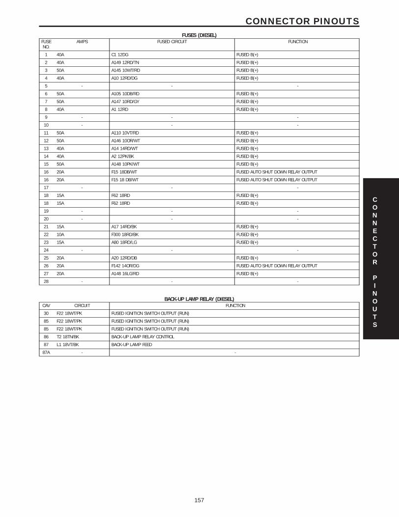
FUSES (DIESEL)FUSENO.
AMPS FUSED CIRCUIT FUNCTION
1 40A C1 12DG FUSED B(+)
2 40A A149 12RD/TN FUSED B(+)
3 50A A145 10WT/RD FUSED B(+)
4 40A A10 12RD/DG FUSED B(+)
5 - - -
6 50A A105 10DB/RD FUSED B(+)
7 50A A147 10RD/GY FUSED B(+)
8 40A A1 12RD FUSED B(+)
9 - - -
10 - - -
11 50A A110 10VT/RD FUSED B(+)
12 50A A146 10OR/WT FUSED B(+)
13 40A A14 14RD/WT FUSED B(+)
14 40A A2 12PK/BK FUSED B(+)
15 50A A148 10PK/WT FUSED B(+)
16 20A F15 18DB/WT FUSED AUTO SHUT DOWN RELAY OUTPUT
16 20A F15 18 DB/WT FUSED AUTO SHUT DOWN RELAY OUTPUT
17 - - -
18 15A F62 18RD FUSED B(+)
18 15A F62 18RD FUSED B(+)
19 - - -
20 - - -
21 15A A17 14RD/BK FUSED B(+)
22 10A F300 18RD/BK FUSED B(+)
23 15A A80 18RD/LG FUSED B(+)
24 - - -
25 20A A20 12RD/DB FUSED B(+)
26 20A F142 14OR/DG FUSED AUTO SHUT DOWN RELAY OUTPUT
27 20A A148 16LG/RD FUSED B(+)
28 - - -
BACK-UP LAMP RELAY (DIESEL)CAV CIRCUIT FUNCTION
30 F22 18WT/PK FUSED IGNITION SWITCH OUTPUT (RUN)
85 F22 18WT/PK FUSED IGNITION SWITCH OUTPUT (RUN)
85 F22 18WT/PK FUSED IGNITION SWITCH OUTPUT (RUN)
86 T2 18TN/BK BACK-UP LAMP RELAY CONTROL
87 L1 18VT/BK BACK-UP LAMP FEED
87A - -
CONNECTOR
PINOUTS
157
CONNECTOR PINOUTS

RIGHT REAR LAMP ASSEMBLY - BLACK 6 WAYCAV CIRCUIT FUNCTION
1 L1 18VT/BK BACK-UP LAMP FEED
2 L95 18DG/YL (BUILT-UP-EXPORT)
REAR FOG LAMP RELAY OUTPUT
3 L7 18BK/YL PARK LAMP RELAY OUTPUT
4 L62 18BR/RD RIGHT TURN SIGNAL
5 Z151 18BK GROUND
6 L50 18WT/TN PRIMARY BRAKE SWITCH SIGNAL
SHIFTER ASSEMBLY (C201 DIESEL) - WHITE 12 WAYCAV CIRCUIT FUNCTION
1 - -
2 - -
3 - -
4 K2 20WT/PK SECONDARY BRAKE SWITCH SIGNAL
5 D25 20RD PCI BUS
6 - -
7 D21 20PK SCI TRANSMIT
8 F12 20DB/WT FUSED IGNITION SWITCH OUTPUT (RUN-START)
9 T2 20TN/BK BACK-UP LAMP RELAY CONTROL
10 Z234 20WT GROUND
11 T41 20BK/WT PARK/NEUTRAL POSITION SWITCH SENSE
12 F991 20OR/DB FUSED IGNITION SWITCH OUTPUT (RUN-START)
SHIFTER ASSEMBLY C1 (DIESEL) - BLACK 12 WAYCAV CIRCUIT FUNCTION
1 F991 20OR/DB FUSED IGNITION SWITCH OUTPUT (RUN-START)
2 F991 20OR/DB FUSED IGNITION SWITCH OUTPUT (RUN-START)
3 F991 20OR/DB FUSED IGNITION SWITCH OUTPUT (RUN-START)
4 T2 20TN/BK BACK-UP LAMP RELAY CONTROL
5 D25 20OR PCI BUS
6 W0 20DB/WT SHIFTER C1 SENSE
7 W1 20VT/WT SHIFTER C2 SENSE
8 W2 20VT SHIFTER C3 SENSE
9 W3 20BK SHIFTER C4 SENSE
10 W4 20PK/OR SHIFTER C5 SENSE
11 Z234 20WT GROUND
12 Z234 20WT GROUND
SHIFTER ASSEMBLY C2 (DIESEL) - 6 WAYCAV CIRCUIT FUNCTION
1 - -
2 - -
3 F12 20DB/WT FUSED IGNITION SWITCH OUTPUT (RUN-START)
4 K2 20WT/PK SECONDARY BRAKE SWITCH SIGNAL
5 F991 20OR/DB FUSED IGNITION SWITCH OUTPUT (RUN-START)
6 Y1 20DB/PK PARK LOCKOUT SOLENOID CONTROL
CONNECTOR
PINOUTS
158
CONNECTOR PINOUTS

TRANSFER CASE POSITION SENSOR - BLACK 2 WAYCAV CIRCUIT FUNCTION
1 K77 20BR/WT (DIESEL) TRANSFER CASE POSITION SENSOR SIGNAL
1 K77 18LG/BK (GAS) TRANSFER CASE POSITION SENSOR SIGNAL
2 K4 20BK/LB (DIESEL) SENSOR GROUND
2 K4 18BK/LB (GAS) SENSOR GROUND
TRANSMISSION CONTROL MODULE C1 (DIESEL) - BLACK 18 WAYCAV CIRCUIT FUNCTION
1 D21 20PK SCI TRANSMIT
2 - -
3 W4 20PK/OR SHIFTER C5 SENSE
4 Y1 20DB/PK PARK LOCKOUT SOLENOID CONTROL
5 - -
6 - -
7 T41 20BK/WT PARK/NEUTRAL POSITION SWITCH SENSE
8 - -
9 - -
10 - -
23 - -
24 - -
25 W0 20DB/WT SHIFTER C1 SENSE
26 W1 20VT/WT SHIFTER C2 SENSE
27 W2 20VT SHIFTER C3 SENSE
28 W3 20BK SHIFTER C4 SENSE
29 F991 20OR/DB FUSED IGNITION SWITCH OUTPUT (RUN-START)
30 Z234 20WT GROUND
TRANSMISSION CONTROL MODULE C2 (DIESEL) - BLACK 14 WAYCAV CIRCUIT FUNCTION
12 T52 18RD/BK N2 INPUT SPEED SENSOR
13 T39 18GY/LB SENSOR SUPPLY VOLTAGE
14 T60 18BR 1-2/4-5 SOLENOID CONTROL
15 T159 18DG/WT 3-4 SOLENOID CONTROL
16 T119 18WT/DB 2-3 SOLENOID CONTROL
17 T120 18LG TCC SOLENOID CONTROL
33 T13 18DB/BK SENSOR GROUND
34 T54 18VT TEMP SENSOR - P/N SWITCH
35 T14 18LG/WT N3 INPUT SPEED SENSOR
36 T591 18YL/DB MODULATION PRESSURE SOLENOID CONTROL
37 T118 18YL/DB SHIFT PRESSURE SOLENOID CONTROL
38 T16 18RD SOLENOID SUPPLY VOLTAGE
H1 D52 18LG/WT CAN C BUS(+)
L2 D51 18DG/WT CAN C BUS(-)
CONNECTOR
PINOUTS
159
CONNECTOR PINOUTS

TRANSMISSION SOLENOID ASSEMBLY (DIESEL) - BLACK 13 WAYCAV CIRCUIT FUNCTION
1 T14 18LG/WT N3 INPUT SPEED SENSOR
2 T591 18YL/DB MODULATION PRESSURE SOLENOID CONTROL
3 T52 18RD/BK N2 INPUT SPEED SENSOR SIGNAL
4 T54 18VT TEMP SENSOR - P/N SWITCH
5 - -
6 T16 18RD SOLENOID SUPPLY VOLTAGE
7 T39 18GY/LB SENSOR SUPPLY VOLTAGE
8 T119 18WT/DB 2-3 SOLENOID CONTROL
9 T159 18DG/WT 3-4 SOLENOID CONTROL
10 T118 18YL/DB SHIFT PRESSURE SOLENOID CONTROL
11 T120 18LG TCC SOLENOID CONTROL
12 T13 18DB/BK SENSOR GROUND
13 T60 18BR 1-2/4-5 SOLENOID CONTROL
CONNECTOR
PINOUTS
160
CONNECTOR PINOUTS

10.0 SCHEMATIC DIAGRAMS
SCHEMATIC
DIAGRAMS
161
SCHEMATIC DIAGRAMS

NOTES
162

11.0 CHARTS AND GRAPHS
11.1 SHIFT LEVER ERROR CODES
11.2 SHIFTER SWITCH STATES
CHARTS
AND
GRAPHS
163
CHARTS AND GRAPHS

11.3 5 VOLT SQUARE WAVE - TYPICAL PATTERNCHARTS
AND
GRAPHS
164
CHARTS AND GRAPHS

11.4 TRANMISSION TEMP SENSOR CHARTS
AND
GRAPHS
165
CHARTS AND GRAPHS

NOTES
166