table of contents - galionsys · table of contents about this manual ... for maximum expandability,...
TRANSCRIPT

Table of Contents
About This Manual...................................................................................................iChapter 1 Digital Video Recorder Introduction....................................................1Chapter 2 Getting Started.....................................................................................9Chapter 3 Quick Guide to Icons on the Main Screen.........................................15Chapter 4 Configuring the Cameras....................................................................19Chapter 5 Schedule Recording............................................................................23Chapter 6 Account Settings................................................................................27Chapter 7 System Settings.................................................................................31Chapter 8 Alarm Settings...................................................................................43Chapter 9 Alarm Log..........................................................................................51Chapter10 User Log............................................................................................55Chapter11 Configuring General Purpose I/O......................................................57Chapter12 Pan Tilt Zoom...................................................................................61Chapter13 Playback............................................................................................67Chapter14 Remote Surveillance...........................................................................81Appendix A Backup to NAS...............................................................................111Appendix B NTP................................................................................................113Appendix C Audio..............................................................................................115Appendix D Multi-Playback...............................................................................119Appendix E Troubleshooting..............................................................................121Appendix F Configuring ActiveX........................................................................125Announcement....................................................................................................................127
About This Manual
This manual is designed to assist customers in the use of the Digital VideoRecorder produced by our company. Information in this document has beencarefully designed and arranged, and also checked for accuracy beforepublication; however, no guarantee is given as to the correctness of the con-tents in print and depiction. Corrections will be made as necessary in subse-quent editions for the benefit of our customers. No guarantee or other hints inany form about the content or usage of this manual is expressed. Also, theinformation contained in this document is subject to change without notice.
Edition 3.5.4
2005. JUN.
Copyright
This publication contains information that is protected by copyright. No part ofit may be reproduced, transmitted, transcribed, or translated into any languagewithout permission from the copyright holders.
Copyright © 2005
All rights reserved.
i

Warning
It is essential that only the supplied special devices be used, and alsoonly the components approved by the manufacturer or the authorizeddealer. The use of unapproved components may cause systemdamage, or give off / receive over-standard electromagnetic radiation.
You are suggested to use the original components produced by ourmanufacturer for your benefit.
Maintenance
Follow these steps and you will increase the working lifetime of yourDVR.
1.Please read the manual and follow the warnings and instruc-tions listed in it.
2.Make sure the Digital Video Recorder is turned off beforeunplugging it.
3.It is a good idea to unplug your Digital Video Recorder when itis not in use.
4.Do not use the Digital Video Recorder in a dusty or dirty workarea; and the dust in the filter net under the cover should becleaned at regular intervals.
5.Clean your Digital Video Recorder exterior casing regularlywith a soft cloth. If you use a cleanser, make sure that it isonly mild detergent and not a solvent. Make sure that theDigital Video Recorder's power is off when you clean it. Aftercleaning, allow 30 minutes drying time before you use it.
6.Remember to clean your display at regular intervals. Spraywindow cleanser onto a soft cloth and then wipe the display.Do not spray the cleanser directly onto the display.
7.Do not operate your Digital Video Recorder near a source ofheat or in direct sunlight.
8.Do not use the Digital Video Recorder in a potentially flam-mable work area.
9.Do not use your Digital Video Recorder on an unstable workingsurface. This will prevent your Digital Video Recorder fromfalling or being knocked over and damaged.
ii
10.Do not store objects on the top of your Digital Video Recorder.Do not exert pressure on the Digital Video Recorder, it maydamage the LCD display.
11.Do not use the Digital Video Recorder near water or otherliquids, or in rainy/moist situations. If liquid gets into yourDigital Video Recorder, turn it off and take it to your dealer forinspection.
12.Wait for a period of one minute before restarting your DigitalVideo Recorder after turning it off, in order to avoid damage tothe hard disk.
iii

1
Chapter 1
DIGITAL VIDEO RECORDER INTRODUCTION
Thank you for your purchasing the Digital Video Recorder (DVR) developedby our company! This product has already obtained CE, FCC, BSMI Class A
Certifications .
Our company has developed 4-, 8-, 12-, 16-CH DVR system,DVR centralmonitoring system and various storage devices, aimed at various securitysurveillance applications. The entire series of products utilizes the mostadvanced digital technology and provides a broad range of functions, inorder to completely satisfy your DVR application requirements.
Our DVR system has built-in digital compression technology for recordingand streaming video. Generally speaking, an CCD camera can deliver clear,crisp images at about 30 fps (NTSC — National Television Standards Com-mittee — US Television Standard) (25fps for PAL—Phase Alternating Line— European Television Standard) — real continuous motion requires 24fps (frames per second, standing for the number of the images delivered inone second.) The high-performance processor and quick I/O connectionnot only provide you with the capability to monitor the camera in real-timemode, but also utilize the extra processing power to allow for a high framerate for recording and remote monitoring via I.E. browser, so that there willbe a minimal loss of video frames. Users can determine the actual framerate required for recording and remote monitoring according to the amountof allocated disk space and the bandwidth available.
For maximum expandability, the system provides a Network Card, allowingcustomers to connect a computer system to monitor remotely through thenetwork. A built-in 3½" floppy disk drive (FDD) may be used for outputtingvideo documents, and other optional items include memory, storage/backupdevices, and alarm functions. Customers can choose to purchase expand-able modules according to actual needs.
This User’s Guide describes all features of the Digital Video Recorder in aneasy-to-read yet thorough manner. The primary goals of this chapter are toidentify the main components of the Digital Video Recorder and to provide aquick reference of the DVR functions for experienced DVR users.
Chapter 1
2
Unpacking the DVR
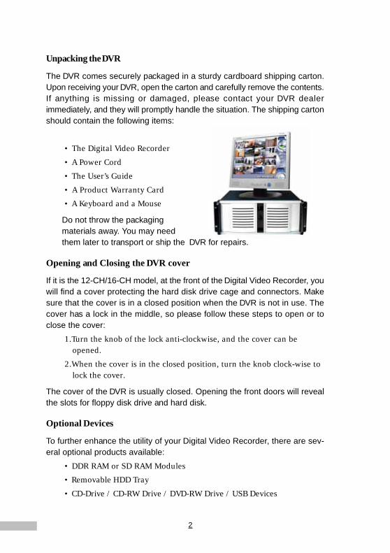
The DVR comes securely packaged in a sturdy cardboard shipping carton.Upon receiving your DVR, open the carton and carefully remove the contents.If anything is missing or damaged, please contact your DVR dealerimmediately, and they will promptly handle the situation. The shipping cartonshould contain the following items:
• The Digital Video Recorder
• A Power Cord
• The User’s Guide
• A Product Warranty Card
• A Keyboard and a Mouse
Do not throw the packagingmaterials away. You may needthem later to transport or ship the DVR for repairs.
Opening and Closing the DVR cover
If it is the 12-CH/16-CH model, at the front of the Digital Video Recorder, youwill find a cover protecting the hard disk drive cage and connectors. Makesure that the cover is in a closed position when the DVR is not in use. Thecover has a lock in the middle, so please follow these steps to open or toclose the cover:
1.Turn the knob of the lock anti-clockwise, and the cover can beopened.
2.When the cover is in the closed position, turn the knob clock-wise tolock the cover.
The cover of the DVR is usually closed. Opening the front doors will revealthe slots for floppy disk drive and hard disk.
Optional Devices
To further enhance the utility of your Digital Video Recorder, there are sev-eral optional products available:
• DDR RAM or SD RAM Modules
• Removable HDD Tray
• CD-Drive / CD-RW Drive / DVD-RW Drive / USB Devices

3
Chapter 1• 4 Din/Dout GPIO Cable
• Exchangeable IDE Hard Disk/ IDE Expansion Board/ Disk Array/NAS Devices / DAT Devices
• RS-232 Interface Modem
• IP sharing device
• UPS (Uninterruptible Power Supply)
Overview of the Digital Video Recorder's Hardware Features
This section provides an overview of the Digital Video Recorder’s features asfollows:
CPU The central processing unit (CPU) is the DVR’s key hardware feature; it acts as the brain of the Digital Video Recorder, performing all the computing functions and orchestrating the actions of the system.
Upgradeable System Memory
Memory can be upgraded to 256MB
Power Management
The DVR features sophisticated power management built into the complete BIOS Setup program─Integrated Smart Charger Circuit, which is designed to restart the DVR automatically as soon as the power is resumed after a power cut.
FDD Module
The DVR comes with a built-in FDD (Floppy Disk Drive) module. The FDD can use 1.44MB high-density 3.5" floppy diskettes.
Removable HDD Tray
The DVR comes with a 3.5” hard disk. The hard drive can easily be removed and replaced with multiple hard drives for the purpose of data backup or expansion.

4
Identifying External Components
Please refer to the text and diagrams below to identify all external compo-nents and accessories of the Digital Video Recorder.
Front View
Figure 1-1: Front View of the DVR
Front Inside ViewPlease refer to Figure 1-2 and the following descriptions to identify thecomponents on the front side of the Digital Video Recorder.
Figure 1-2: Front Inside View of the Digital Video Recorder
4 or 8 Channel Type 12 or16 Channel Type
4 or 8 Channel Type
12 or 16 Channel Type
5
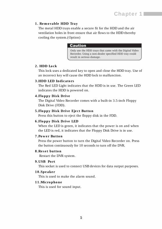
Chapter 11. Removable HDD Tray
The metal HDD trays enable a secure fit for the HDD and the airventilation holes in front ensure that air flows to the HDD therebycooling the system.(Option)
2. HDD LockThis lock uses a dedicated key to open and close the HDD tray. Use ofan incorrect key will cause the HDD lock to malfunction.
3.HDD LED IndicatorsThe Red LED Light indicates that the HDD is in use. The Green LEDindicates the HDD is powered on.
4.Floppy Disk DriveThe Digital Video Recorder comes with a built-in 3.5-inch FloppyDisk Drive (FDD).
5.Floppy Disk Drive Eject ButtonPress this button to eject the floppy disk in the FDD.
6.Floppy Disk Drive LEDWhen the LED is green, it indicates that the power is on and whenthe LED is red, it indicates that the Floppy Disk Drive is in use.
7.Power ButtonPress the power button to turn the Digital Video Recorder on. Pressthe button continuously for 10 seconds to turn off the DVR.
8.Reset button Restart the DVR system.
9.USB PortThis socket is used to connect USB devices for data output purposes.
10.SpeakerThis is used to make the alarm sound.
11.MicrophoneThis is used for sound input.

6
Rear ViewPlease refer to Figure 1-3 and the following descriptions to identify thecomponents on the rear side of the Digital Video Recorder.
Figure 1-3: Rear View of Digital Video Recorder

7
Chapter 11. Power Fan
This is used to cool the power supply.
2. System Ventilation FanThis fan ventilates the entire system.
3.BNC Camera InputUse BNC pigtail adaptor to connect NTSC or PAL compatible cameras.See Figure1-3; the position and numbering of the on-screen cameraoutput is determined by the slot and channel numbering sequence ofthe cards. For example, camera 1 would be connected to channel 1 ofcard 1, camera 2 would be connected to channel 2 of card 1, camera5 would be connected to channel 1 of card 2, etc., since there are 4available channels per card slot.
Figure 1-4: BNC pigtail adaptor
4.Ethernet LAN PortUse an RJ-45 LAN cable to connect to a LAN or Internet.
5.VGA Display PortThis port is used to connect an external CRT or TFT display.
6.Printer PortThis port is used to connect a printer to the DVR.
7.PS/2 Keyboard PortThis port connects a PS/2 compatible keyboard.
8.PS/2 Mouse PortThis port connects a PS/2 compatible mouse.
9.Power Cord SocketThis socket is used to connect the power cord to the wall poweroutlet.
10.Voltage SwitchThe voltage switch regulates the voltage specifications of 110/220V,as required for different regions. Switch the voltage according toyour region’s requirements.

8
11.Power SwitchUse this switch to power the machine on or to cut off the power.
12.RS-232 PortConnect this socket to the MODEM to enable the sending of alarmalerts, or to convert RS-232 to RS-485 devices to control the PTZvideo camera.
13.USB PortThis socket is used to connect USB devices for data output.
14.SpeakerThis is used to make the alarm sound.
15.MicrophoneThis is used for sound input.
Preparing the Digital Video Recorder for Operation
To prepare your Digital Video Recorder for operation, you should first con-nect all peripheral devices. Make sure the DVR is turned off before you dothis. Once you have connected all peripheral devices, check that the volt-age switch is appropriate for your region (115/230). Make sure the floppydrive does not contain a diskette, and there are no discs in the CD / CD-RWdrive; if there are any discs, press the eject button to eject an inserted disc.
9
Chapter 2Chapter 2
GETTING STARTED
This chapter explains what you need to do after turning on your Digital VideoRecorder. Experienced DVR users may skip this chapter and then return toit for reference if there are any problems in reading other chapters.
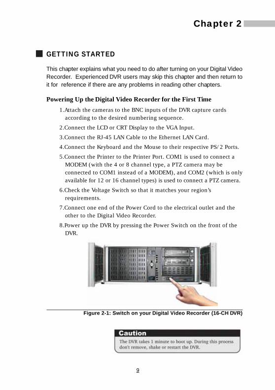
Powering Up the Digital Video Recorder for the First Time1.Attach the cameras to the BNC inputs of the DVR capture cards
according to the desired numbering sequence.
2.Connect the LCD or CRT Display to the VGA Input.
3.Connect the RJ-45 LAN Cable to the Ethernet LAN Card.
4.Connect the Keyboard and the Mouse to their respective PS/2 Ports.
5.Connect the Printer to the Printer Port. COM1 is used to connect aMODEM (with the 4 or 8 channel type, a PTZ camera may beconnected to COM1 instead of a MODEM), and COM2 (which is onlyavailable for 12 or 16 channel types) is used to connect a PTZ camera.
6.Check the Voltage Switch so that it matches your region’srequirements.
7.Connect one end of the Power Cord to the electrical outlet and theother to the Digital Video Recorder.
8.Power up the DVR by pressing the Power Switch on the front of theDVR.
Figure 2-1: Switch on your Digital Video Recorder (16-CH DVR)

10
Once the boot process is complete, the Digital Video Recorder will directlydisplay all the connected cameras (see Figure 2-2), enabling the user tocheck them conveniently. If there is a screen displaying NO SIGNAL in blue,it means the respective camera is either inactive or not working. Please referto your camera manual for further assistance.
Figure 2-2: The first viewable screen (Main Screen)
The first viewable screen not only gives the user a first glance at the GUI(Graphical User Interface) but also shows all of the connected cameras. Theviewable screen takes up 75% of the screen, while the controls are posi-tioned to the right of the viewable cameras.
Status Lights:The lights on the top left corner show the status of recordingoperation. There are Red Lights, Blue Lights and Green Lights.
Green Light e means Scheduled
Red Light e means recording
Blue Light e means no recording

11
Chapter 2
Right-side Toolbar
Figure 2-3: Right-side Toolbar
1.System Time / Version IndicatorThis indicator displays the Date/Month/Year and Time in digitalformat; and also shows the Version before logging on.
2.Settings IconClick this icon to enter the Settings Menu.
3.Playback IconClick this icon to enter the Playback Menu.
4.Log-on IconClick this icon to enter the Log-on / Shut-down Menu.
5.Single View IconClick this icon to run in Single view mode.
6.Quad View Icon
Understanding the DVR Main Screen
When starting the Digital Video Recorder for the first time, please make surethat you understand all of the DVR’s icons before moving on. Here is anexplanation of the relevant icons on the main screen.
12
Clicking this icon will display four camera images on the screen.
7.9-Camera Viewable IconClicking this icon will display nine camera images on the screen.
8.16-Camera Viewable IconClicking this icon will display sixteen camera images on the screen.
9.Full Screen IconClicking this icon will show the viewable cameras in full screen.
10.Total & Remaining HDD Space IndicatorThe indicator displays total available HDD space and how muchspace is remaining on the available HDD. If the DVR begain to cyclicrecording, it will display “Recycle”.
Here is an explanation of the relevant icons on the botton toolbar.
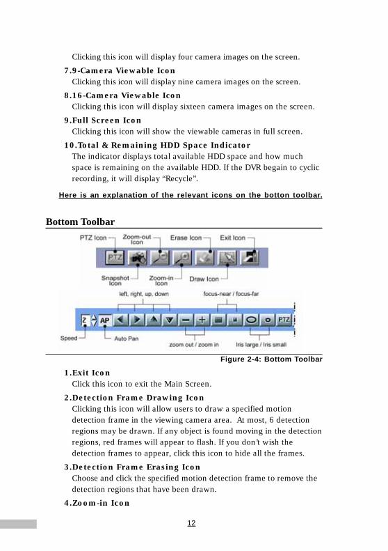
Bottom Toolbar
Figure 2-4: Bottom Toolbar
1.Exit IconClick this icon to exit the Main Screen.
2.Detection Frame Drawing IconClicking this icon will allow users to draw a specified motiondetection frame in the viewing camera area. At most, 6 detectionregions may be drawn. If any object is found moving in the detectionregions, red frames will appear to flash. If you don’t wish thedetection frames to appear, click this icon to hide all the frames.
3.Detection Frame Erasing IconChoose and click the specified motion detection frame to remove thedetection regions that have been drawn.
4.Zoom-in Icon

13
Chapter 2Clicking this icon will zoom in the selected camera images or, justdouble-click the respective camera image on the main screen.
5.Zoom-out IconClicking this icon will zoom out the selected camera images. Or youcan just click the right key of the mouse to zoom the images out.
6.Snapshot IconClicking this icon will save a single picture of the camera image intothe database or for printing.
7.PTZ IconClicking this icon will allow users to view more icons that will helpin controlling the PTZ camera more effectively.
Power the DVR on and off
Only “admin” can be login to the DVR while the DVR is operated at first time.Because there are no other users admitted by the system.
First time operating the system, it will auto-login to the DVR main screen.Enable/ Disable the “auto-login”, please read Chapter 7: System Settings.Adding DVR users, please read Chapter 6: Account Settings. Meanwhile,please shutdown the DVR as following:
Re-loginWhen starting the Digital Video Recorder for the first time, the system canonly provide "admin" authority for the Supervisor, with no other rights for theremaining users. So initially, you will have to log on with the right of "admin".
The first time the system is started, it will log on automatically to enter theDVR Main Screen. For instructions relating to how to start / stop systemauto log-on, please refer to Chapter 7--System Settings. Chapter 6--Ac-count Settings explains the process of creating users to access the DVR.Now,to shutdown your DVR, please do the following:
1. Step 1: Click the “Log-on” Icon on the right..............................
2. Step 2: Under User name field type in or select ”admin” (default),under Password field type in the password or “admin” (default).
3. Step 3: Click the “Login” button.

14
Figure2-5: Logging into the system
Shutting Down the System
1. Click the Log-on Icon.......................................................................
2. DVR will popup a dialog for you to confirm the logout.
3. Click "Confirm" to confirm it, then it can be chose to "Login" or "Shutdown".
Figure2-6:Shut down the system
4. Enter or choose "admin" in the User name field: enter the passwordor the default password "admin".
5.Click the “Shut down” to shutdown the system.
Figure 2-7: Shutting down the system
After logout the DVR system, the software version of the DVR system willbe shown on the top right of the screen, for example....................
15
Chapter 3Chapter 3
QUICK GUIDE TO ICONS ON THE MAIN SCREEN
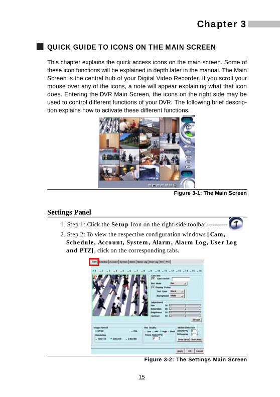
This chapter explains the quick access icons on the main screen. Some ofthese icon functions will be explained in depth later in the manual. The MainScreen is the central hub of your Digital Video Recorder. If you scroll yourmouse over any of the icons, a note will appear explaining what that icondoes. Entering the DVR Main Screen, the icons on the right side may beused to control different functions of your DVR. The following brief descrip-tion explains how to activate these different functions.
Figure 3-1: The Main Screen
Settings Panel1. Step 1: Click the Setup Icon on the right-side toolbar-----------
2. Step 2: To view the respective configuration windows [Cam,Schedule, Account, System, Alarm, Alarm Log, User Logand PTZ], click on the corresponding tabs.
Figure 3-2: The Settings Main Screen

16
Single View Camera Screen1.Step 1: Click the Single View Camera Icon on the right-side toolbar
------------------------------------------------------------------------------
2.Step 2: The image will expand to single view mode (As shown below)
Figure 3-4: The Single and The Quad Camera View Screen
Clicking separate windows will display different settings screens. The firstwindow is the camera screen. Please refer to the instructions later on inthis manual.
Playback Panel
1.Step 1: Click the Playback Icon on the right-side toolbar------
2.Step 2: View the video database under the Playback Screen. Click ona selected file and open the recorded data. (The red circle indicatesthe playback image).
Figure 3-3: The Playback Screen
17
Chapter 3The DVR system can be configured with a Single View Camera Screenwhich could display different camera viewpoints at 6-second intervals. Moredetails on this mode are mentioned in Chap 7.
Quad Camera View Screen1.Step 1: Click the Quad View Camera Icon on the right-side toolbar
--------------------------------------------------------------------------------
2.Step 2: The screen will display four camera images in one screen. Ifyour DVR system has 16 cameras, this view can be configured todisplay four different camera viewpoints at 6-second intervals.
9-Camera View Screen
1.Step 1: Click the 9-Camera View Icon on the right-side toolbar-
2.Step 2: The screen will display nine camera images in one screen. Ifyour DVR system has 16 cameras, this view can be configured todisplay nine different camera viewpoints at 6-second intervals.
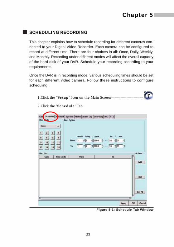
Figure 3-5: The Nine-Camera and The 16-Camera View Screen
16-Camera View Screen1.Step 1: Click the 16-Camera View Icon on the right-side toolbar
............................................................................................................
2.Step 2: Sixteen camera images will be displayed in one screen.

18
Full Screen Mode
1.Step 1: Click the Full Screen View Icon on the right-side toolbar...........................................................................................................
2.Step 2: The screen will display all or the selected cameras connectedto the DVR in Full Screen Mode. If the system has 16 cameras,sixteen camera images will occupy the entire screen.
3.Step 3: Click the right key of the mouse to resume original status.
Figure 3-6: The Full-Screen Camera View Screen

19
Chapter 4Chapter 4
CONFIGURING THE CAMERAS
This chapter explains how to set and configure the cameras connected toyour Digital Video Recorder. Once you have connected the video camerasyou need to your DVR, you need to enter the Setup Menu to configure eachindividual camera. Here users can select the camera information shown on-screen, set the background colors, adjust the lighting of each camera, setthe image format and resolution, change the image quality, frame rate, andadjust the sensitivity of motion detection.
Please follow these steps to change the settings of each camera:1.Click the Setup Icon on the Main Screen to enter the camera
settings screen-------------------------------------------------------------
2.Click the Diamond Icon to choose the camera you want to configure.
3.The small window under the camera selection will then display theselected camera in real-time mode.
Figure 4-1: Main Camera Settings Window
Naming Cameras• If the selected camera has been set up, while having not started
working, a grey screen will be shown. You should click the checkboxunder “Cam Info” to enter a name for the camera to start thecamera screen.
• If you start a camera before its installation, this camera will display

20
NO SIGNAL in blue, and this condition will waste system resources.So don’t enable a camera before installing it.
Figure 4-2: Camera Naming Field
Setting Recording Mode• Under “Rec Mode” choose one of the three options:i. No Recording (The camera will stop recording)
ii.Recording (The camera records at all times)
iii.Scheduled (A particular time should be scheduled for recordingunder this option)
These three types of recording modes will be activated when thealarm starts.
Adding Text & Text Background Color• Click the “Display Status”checkbox to change the text color and
background color.
• Text colors: For Text Color users can choose to have text in Black,Red, Green, Blue and White
• Background color: For Background Color users can choose to haveBlack, Red, Green, Blue and White
Adjusting Picture Quality
• Under “Adjustment” users can choose various settings respectivelyfor
i. “Hue”- This is the attribute of colors that permits them to be classedas Red, Yellow, Green, Blue, or an intermediate between any contigu-ous pair of these colors
ii. “Saturation”- This is the degree of difference from the achromatic
Rec Mode choice No Recording Recording Scheduled
Adding Text &Text BackgroundColor
Naming Cameras

21
Chapter 4light-source color of the same brightness
iii.“Brightness”- This is the attribute of light-source colors by whichemitted light is ordered continuously from light to dark in correla-tion with its intensity
iv.“Contrast”- This is to compare with respect to differences
When changes are made the camera image is automatically updated.To return to previous settings, click *“Default”
*Default: Hue-50 / Saturation-50 / Brightness-50 / Contrast-50
Figure 4-3: Camera image field
Setting Image Format• Under “Image Format” users can select :
i. *“NTSC”- Three settings for image resolution - (160x120, 320x240,or 640x480).
ii. “PAL”- Three settings for image resolution - (176x144, 352x288, or704x576)
Figure 4-4: Image Format Area
Setting Recording Quality
• Under “Recording Quality”, there are four choices: Low, Medium,High and Best. Among them, Low quality is applicable for longtime recording, while Best quality is used for applications whichrequire better image quality.
• Click to choose the proper quality, and use the Frame Rate (f/s: thenumber of pictures that can be recorded per second, dependingon the whole performance of the system) to set the recordingspeed of each camera.

22
Figure 4-5: Recording Quality and Motion Detection Area
Setting Motion DetectionUnder “Motion Detection” users can select:
i. Sensitivity - To set the sensitivity relative to the detected motion(from 1 to 5). The higher the value is, the more sensitive the detec-tion will be. Thus even a very slight stimulation could be respondedto.
ii. Differentia - A factor that distinguishes differences among imagesrelating to entity, state or class.(from 1 to 10)For example, assuming the value to be 1, once the second image isdifferent from the first one, an alarm would be started.
Up to six different Motion Detection Windows can be created in one cameraview.
• Click “Draw Area” : if you want to draw a motion detec-tion frame on the camera images, just drag a frame-sized windowover the desired motion detection area. Continue to do this until allthe needed frames have been drawn (up to 6 detection frames).
• Click “Stop” : After you have clicked drawing area, “DrawArea” will revert to “Stop” . If you don’t want todisplay the detection frames, just press this button to hide all theframes.
• If you would like to cancel current motion detection settings, click“Clear Area” to erase all the frames one by one.
• When all settings are complete, click “Apply” and then “OK” (The screen will return to the main screen).
Motion DetectionSetting Recording Quality
23
Chapter 5Chapter 5
SCHEDULING RECORDING
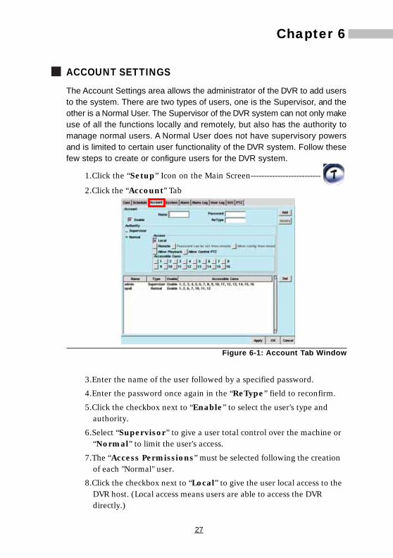
This chapter explains how to schedule recording for different cameras con-nected to your Digital Video Recorder. Each camera can be configured torecord at different time. There are four choices in all: Once, Daily, Weekly,and Monthly. Recording under different modes will affect the overall capacityof the hard disk of your DVR. Schedule your recording according to yourrequirements.
Once the DVR is in recording mode, various scheduling times should be setfor each different video camera. Follow these instructions to configurescheduling:
1.Click the “Setup” Icon on the Main Screen---------------------------
2.Click the "Schedule" Tab
Figure 5-1: Schedule Tab Window

24
3.Under REC Mode (Record Mode), users have four choices:
i. Once - Provides a recording option for a specified period of time
Figure 5-2: Record Mode Selection Bar (Once)
ii. Daily - Provides a recording option for Hours and Minutes everyday.
Figure 5-3: Record Mode Selection Bar (Daily)
iii. Weekly - Provides a recording option for users to set the day(Sun. through Sat.) and time for recording every week.
Figure 5-4: Weekly Schedule Settings
iv. Monthly - Provides a recording option that allows users to set thedate and time for recording every month.
Figure 5-5: Monthly Schedule Settings

25
Chapter 54.After you have selected the record mode and record option, choose
the camera you want to configure (you can also choose the camerafirst and then the record mode).
5.Click the “Add” button. The relative information will beshown in the schedule recording List.
6.If you wish to delete a particular entry, select the entry and click the
“Delete” button.
8.If you wish to delete all the entries, click the “Del All”
button.
9.Click “Apply” , and “OK” to confirm your
corrections. The screen will return to viewer mode.
Once Scheduling
By choosing the “Once” scheduling mode of the DVR, users can firstselect the Day, Month, and Year, and then select a particular time on thatdate to record. The advantage of this operation is to set different times foreach individual camera, allowing users to record with different cameras atvarious times. This function can be used for PTZ, Dome cameras andnormal cameras.
1.Select the “Once” option
2.Select the serial number of the camera you wish to configure. Thenthe selected camera will appear in high light mode.
3.Select the recording duration.
figure 5-6: Duration Selection
4.Click the “Add” button.

26
Daily SchedulingBy choosing the “Daily” scheduling mode of the DVR, users can set a par-ticular period for recording during one day.
1.Select the “Daily” option
2.Select the camera you wish to configure.
3.Select the recording duration.
Figure 5-7: Duration Selection
4.Click the “Add” button.
*The settings for Weekly and Monthly are the same as above.
Deleting Schedule SettingsDeleting recorded data will permanently delete all related information fromthe hard disk drive, thus freeing-up disk space.
1.Select the recorded scheduled period from the list.
Figure 5-8: Deleting Schedule Settings
2.Click the “Delete” button.
To Delete All
1.Click the “Del all” button .
27
Chapter 6
ACCOUNT SETTINGS
The Account Settings area allows the administrator of the DVR to add usersto the system. There are two types of users, one is the Supervisor, and theother is a Normal User. The Supervisor of the DVR system can not only makeuse of all the functions locally and remotely, but also has the authority tomanage normal users. A Normal User does not have supervisory powersand is limited to certain user functionality of the DVR system. Follow thesefew steps to create or configure users for the DVR system.
1.Click the “Setup” Icon on the Main Screen--------------------------
2.Click the “Account” Tab
Figure 6-1: Account Tab Window
3.Enter the name of the user followed by a specified password.
4.Enter the password once again in the “ReType” field to reconfirm.
5.Click the checkbox next to “Enable” to select the user's type andauthority.
6.Select “Supervisor” to give a user total control over the machine or“Normal” to limit the user's access.
7.The “Access Permissions” must be selected following the creationof each "Normal" user.
8.Click the checkbox next to “Local” to give the user local access to theDVR host. (Local access means users are able to access the DVRdirectly.)
Chapter 6
28
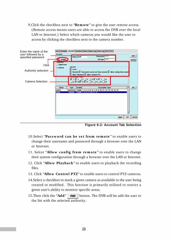
9.Click the checkbox next to “Remote” to give the user remote access.(Remote access means users are able to access the DVR over the localLAN or Internet.) Select which cameras you would like the user toaccess by clicking the checkbox next to the camera number.
Figure 6-2: Account Tab Selection
10.Select “Password can be set from remote” to enable users tochange their username and password through a browser over the LANor Internet.
11. Selcet “Allow config from remote” to enable users to changetheir system configuration through a browser over the LAN or Internet.
12. Click “Allow Playback” to enable users to playback the recordingfiles.
13. Click “Allow Control PTZ” to enable users to control PTZ cameras.
14.Select a checkbox to mark a given camera as available to the user beingcreated or modified. This function is primarily utilized to restrict agiven user's ability to monitor specific areas.
15.Then click the “Add” button. The DVR will be add the user tothe list with the selected authority.
Click
Enter the name of theuser followed by aspecified password
Authority selection
Camera Selection

29
Chapter 6To Modify User Settings
1.Select the user.
2.Make the changes in the Main Account Panel
3.Click the “Modify” button.
4.Click “Apply” , then “OK” to confirm changes
To Delete Users
1.Select the user
2.Click “delete”
3.Click “Apply” , then “OK” to confirm the changes

30
- NOTES -
31
Chapter 7Chapter 7
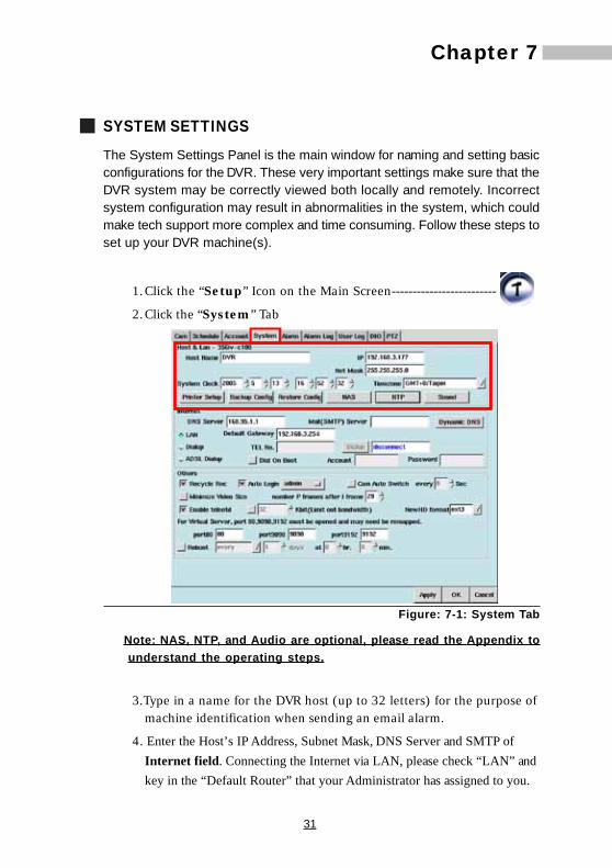
SYSTEM SETTINGSThe System Settings Panel is the main window for naming and setting basicconfigurations for the DVR. These very important settings make sure that theDVR system may be correctly viewed both locally and remotely. Incorrectsystem configuration may result in abnormalities in the system, which couldmake tech support more complex and time consuming. Follow these steps toset up your DVR machine(s).
1.Click the “Setup” Icon on the Main Screen-------------------------
2.Click the “System” Tab
Figure: 7-1: System Tab
Note: NAS, NTP, and Audio are optional, please read the Appendix tounderstand the operating steps.
3.Type in a name for the DVR host (up to 32 letters) for the purpose ofmachine identification when sending an email alarm.
4. Enter the Host’s IP Address, Subnet Mask, DNS Server and SMTP ofInternet field. Connecting the Internet via LAN, please check “LAN” andkey in the “Default Router” that your Administrator has assigned to you.

32
5.Click “Apply” , and “OK” .
ADSL Dial-up and DDNS Set-upIt supports DDNS services for remote site users using fixed host name toconnecting with your DVR, no need to know the real IP address that you realbeen assigned.
1.Check the ADSL dial-up, and enter the account and password ofADSL.
Figure: 7-2: System Tab
2.Click the “Dialup” button. IP address will be shown in this columnwhen connecting succeeded. (You can click “Dial On Boot”)
3.When connection succeeded, click “Dynamic DNS” to show the DDNSsetting window (as below), and enter the account and password.(Please enter a easy-to–memory account)
Figure: 7-3: DDNS setting

33
Chapter 74.Click “Save” to save your settings, and then click “Manual Register”, if
there shows a register success message, which means the domainname (*Note.) will be enabled after 3 mins.
Note: A complete domain name is “Account + .dvrsite.net”
Ex: Account name is dvr124, enter http://dvr124.dvrsite.net to connectthe DVR.
Illustrations of DDNS Service Settings1.Account: Name of domain name. DVR will connect to database
server to check if the account exists, and then check the password.Only the correct account and password will enable the mapping ofdomain name and IP.
2.Password: The password of Account.
3.Auto register after connection: When ADSL disconnection,system will auto redial, sometimes ISP will offer another IP. To enablethis function, system will auto update the correspondent IP whenADSL assigns another one.
4.Manual Register: User register account and IP by himself. (Rightcontrary to “Auto register after connection”)
5.Save: Save the settings. (Only after saving would enable all yoursettings)
Modem Dial-upDVR users can choose modem dial-up for connecting external Network.Windows users can also dialup (using PPP) to DVR for remote monitoring.To set up modem diap-up, do the following:
Check the “Dialup” in the Internet field and enter the “TEL No.” (the phoneno. of ISP), “Account” and “Password” (your account and password fromISP).Then click the “Dail” button to test the dail-up procedure. If successful,“disconnect” field will revert to the IP assigned by ISP. After finished yourtest and idle for 30 seconds, the connection will be hung up by the systemautomatically and the “IP” field will revert to “disconnect” again.
If users chose to connect the external network by modem dialup, DVR willuse modem dialup for alert e-mail delivery, the Network connection wouldbe hung up by the system automatically(idle for 30 seconds) when sendingout the alert e-mail.

34
Figure 7-4: Modem Dial-up settings
Printer SettingThis DVR System is capable of sending static images to a printer. Theseprinted images may reveal more detail than can be seen clearly on the monitor.The system supports a variety of printers; your DVR Supplier will providerelated information. To set up a printer, do the following:
1.click “printer setup”
2.and then the window shows a list of system support printer types.
Figure 7-5: Printer Types
35
Chapter 73.select the “Printer type”, “Paper size”, “Resolution” and
“Color depth”.
4.then click “ok” to confirm.
5.then the window will show if you want to print a test image.
Figure 7-6: To print a test image
6.click “Confirm” to continue and review the resultant testimage.
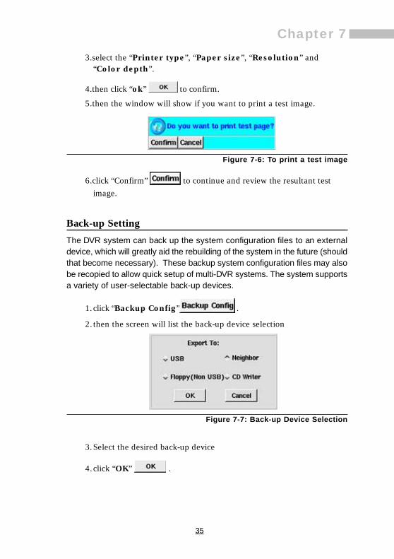
Back-up SettingThe DVR system can back up the system configuration files to an externaldevice, which will greatly aid the rebuilding of the system in the future (shouldthat become necessary). These backup system configuration files may alsobe recopied to allow quick setup of multi-DVR systems. The system supportsa variety of user-selectable back-up devices.
1.click “Backup Config” .
2. then the screen will list the back-up device selection
Figure 7-7: Back-up Device Selection
3.Select the desired back-up device
4.click “OK” .
36
Restoring settings from the Back-up deviceThe DVR system can restore the system configuration settings from theback-up device. The system supports different (user-selectable) back-updevices.
1.Click “Restore Config” .
2.then the screen will show a list of (user-selectable) back-up devices.
Figure 7-8: Restore Device Selection
3.select the device you want.
4. then click “OK” .
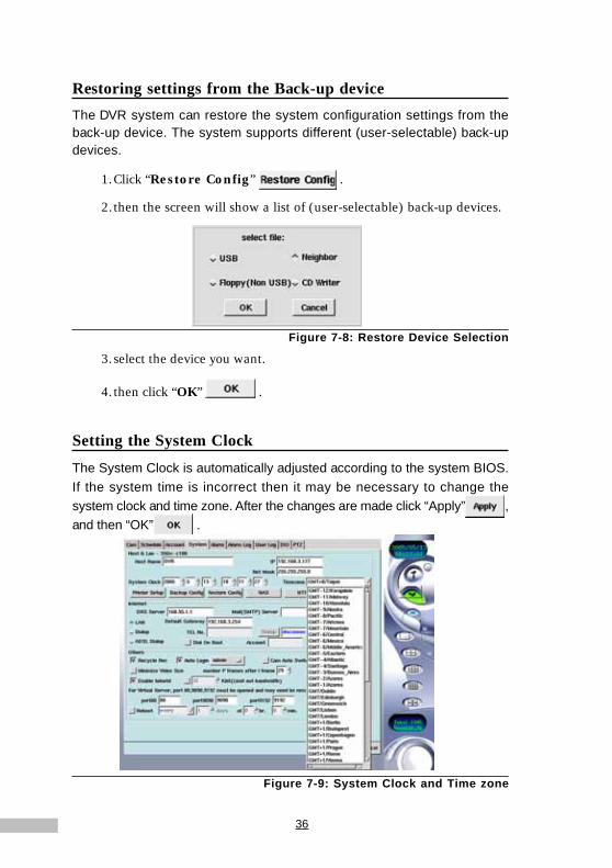
Setting the System Clock
The System Clock is automatically adjusted according to the system BIOS.If the system time is incorrect then it may be necessary to change thesystem clock and time zone. After the changes are made click “Apply” ,and then “OK” .
Figure 7-9: System Clock and Time zone

37
Chapter 7
Other Settings
Recycle RecordingThe first additional option to explore is “Recycle Rec”, which refers to therecycling of recording. When the hard disk is full, if the system has “Re-cycle Rec” enabled, it will continue to record over previously recorded data,so that the recording can continue.
1.Click the “System” Tab.
2.Under “Others” click the checkbox next to “Recycle Rec”.
Figure 7-10: Recycle Rec Option
3.Click “Apply” , then “OK” to activate the changes.
Auto LoginA second option is to give the administrator and other users “Auto Login”status when the system is started. Users with this status do not have to entera username and password every time they log in.
1.Click the “System” Tab.
2.Under “Others” click the checkbox next to “Auto Login”.
3.Select the user account you want to give “Auto Login” status to.
4.Click “Apply” , then “OK” .
38
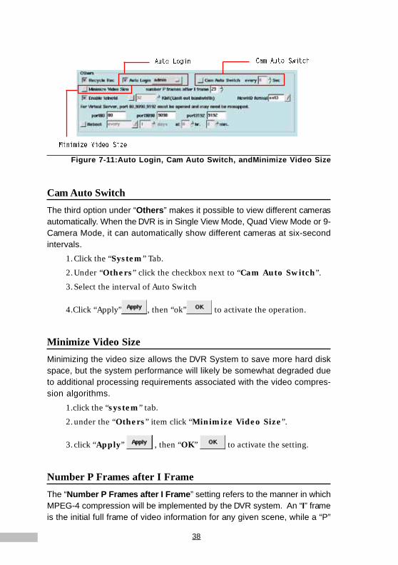
Figure 7-11:Auto Login, Cam Auto Switch, andMinimize Video Size
Cam Auto SwitchThe third option under “Others” makes it possible to view different camerasautomatically. When the DVR is in Single View Mode, Quad View Mode or 9-Camera Mode, it can automatically show different cameras at six-secondintervals.
1.Click the “System” Tab.
2.Under “Others” click the checkbox next to “Cam Auto Switch”.
3.Select the interval of Auto Switch
4.Click “Apply” , then “ok” to activate the operation.
Minimize Video SizeMinimizing the video size allows the DVR System to save more hard diskspace, but the system performance will likely be somewhat degraded dueto additional processing requirements associated with the video compres-sion algorithms.
1.click the “system” tab.
2.under the “Others” item click “Minimize Video Size”.
3.click “Apply” , then “OK” to activate the setting.
Number P Frames after I FrameThe “Number P Frames after I Frame” setting refers to the manner in whichMPEG-4 compression will be implemented by the DVR system. An “I” frameis the initial full frame of video information for any given scene, while a “P”

39
Chapter 7frame consists only of the incremental changes necessary to form the nextframe, rather than an entire new frame. The greater the number of P framesafter each I frame, the more space will be saved on the hard disk, but themore computation will be needed to uncompress the video for playback. Touse this setting:
1.click the “system” tab.
2.under the “Others” item, adjust the “Number P Frames after IFrame” setting (29 is the default setting)
3.click “Apply” , then “OK” to apply the change.
Figure 7-12: Number P Frames after I Frame Settings
Use of the “Number P Frames after I Frame” function will influence1.the quality of the video
2.space used on the hard disk
3.the speed of data transmission
When the P frame function is set to a value higher than the default setting,for every clip of video, less I Frames are sent, so the quality of the image willbe normal, but transmission occurs more quickly and disk space is saved;on the contrary, when the P Frame function is set to a value lower than thedefault setting, more I frames are sent, and the quality of the image will behigh, using more disk space and transmitting more slowly, so users shouldset this function according to their specific requirements. Possible P Framesetting values range from 0-60.
Enable telnetdThe “Enable telnetd” setting refers to start or stop the telnetd daemon. Thedefault setting allow user to login DVR system from remote site using telnetutility (for maintenance). For security consideration, user can disable thisfunction as following:

40
1.click the “System” tab.
2.under the “Others” item, uncheck the “Enable telnetd”.
3.Click “Apply” , then “OK” to apply the change.
Figure 7-13: Enable telnetd Settings
Limit out bandwidthUsers can restrict the total network outbound bandwidth as following:
1.click the “System” tab.
2.under the “Others” item, adjust the outbound bandwidth(64K Bit isthe default setting).
3.Click “Apply” , then “OK” to apply the change.
New HD formatSupport file system including ext3(more stable, the default setting) or vfat.When using vfat format, the HD can be mounted to Windows system forplayback.
1.click the “System” tab.
2.under the “Others” item, select the suitable file system for your newHD.
3.Click “Apply” , then “OK” to apply the change.
Virtual Server SettingIf the DVR is only provided with one legal IP, and besides the DVR host,there are also some other applications (such as interior on-line computersof a company, the network server, the ftp server, the e-mail server...) that
Limit out bandwidth
Enable telnetd New HD format Settings

41
Chapter 7should be used through Internet connections, or there are several DVRhosts providing service outwards, then Virtual Server should be an idealsolution. Virtual Server allows multiple applications to share one legal IP,by assigning various application requirements respectively to the interiorvirtual IP of the company. Basically, functions and setups of Virtual Serverare different depending on the machines’ types. So, please refer to theUser’s Guide for the Virtual Server you purchased. DVR should use threeTCP ports of 80, 9090 and 9192, you will need to open these three TCPports on Virtual Server, or you must fill in the three TCP ports in this item thatcorresponding to the three ports assigned by Virtual Server.
Example:• Network Environment (please consult the Net-Supervisor of your
company):
Exterior legal IP : 211.23.141.2
Interior Network of the company : 192.168.1*
Interior Netmask of the company : 255.255.255.0
Default Router IP of the company : 193.168.1.1
Interior DNS Server : 192.168.1.2
• DVR Host Setting Mode (Virtual IP: 192.168.1.3):
IP : 192.168.1.3
Netmask : 255.255.255
DNS Server : 192.168.1.2
Default Router : 192.168.1.1
Virtual Server IP : 211.23.141.2
• When the above setting is complete, if the users connect throughbrowser to http://211.23.141.2/ , they actually will connect the Hostwith the virtual IP address http://192.168.1.3/.
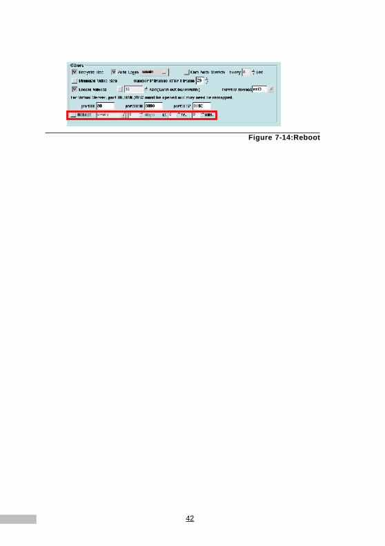
RebootIn order to prevent System occupied unnecessary resources, DVR can beset as auto regular reboot to release other resources, thus to enhance theefficiency of DVR. Please enter the interval days and time for reboot .
Note: Default is no reboot.
42
Figure 7-14:Reboot
43
Chapter 8Chapter 8
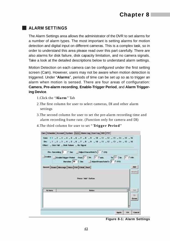
ALARM SETTINGSThe Alarm Settings area allows the administrator of the DVR to set alarms fora number of alarm types. The most important is setting alarms for motiondetection and digital input on different cameras. This is a complex task, so inorder to understand this area please read over this part carefully. There arealso alarms for disk failure, disk capacity limitation, and no camera signals.Take a look at the detailed descriptions below to understand alarm settings.
Motion Detection on each camera can be configured under the first settingscreen (Cam). However, users may not be aware when motion detection istriggered. Under “Alarms”, periods of time can be set up so as to trigger analarm when motion is sensed. There are four areas of configuration:Camera, Pre-alarm recording, Enable-Trigger Period, and Alarm Trigger-ing Device.
1.Click the “Alarm” Tab
2.The first column for user to select cameras, DI and other alarmsettings
3.The second column for user to set the pre-alarm recording time andalarm recording frame rate. (Function only for camera and DI)
4.The third column for user to set “ Trigger Period”
Figure 8-1: Alarm Settings

44
5.Click the checkbox next to “Enable” first, then click “Enable TriggerPeriod” again and enter the period. With this function, the users don’tneed to be in an alarm environment all day long, and they can set theirown desired alarm period according to their actual needs.The “Dura-tion” is for setting the active alarm period (ex: The same kind of alarmwill be overleaped during the Alarm Duration) and the recording framerate when alarm-received. (Which only functions when you selectedthe record trigger mode) It is adjustable for each is camera and DI.
6.Then select one of the Triggering Devices from the “Tab” fieldwindows below.
Alarm Record TriggeringThe following shows how to use Record Alarm:
1.Click the “Alarm” Tab first.
2.From the “General” tab select the “Duration” for motion detectiontriggering and click the checkbox next to “AdjustFrameRateTo”.to select the frame speed for the motion detection.
Figure 8-2: General Field
3.Select the appropriate triggering event for alarm recording(“Camera”, “Din”)
4.Select the entire “Enable” field for to enable 24 hour recordingduration. To set up other record durations, tick off the entire“Enable” field first, then select “Enable” under “Trigger Period”to set the record duration.
5.Click “REC”.
6.Click “Add”
7.Click “Apply” , then “OK” to activate.

45
Chapter 8Alarm Sound Triggering
Activating the Alarm Sound parameter enables sounding of the alarm at thetime of alarm condition detection. Follow the instructions below to set theAlarm Sound.
1.Click the “Alarm” Tab first.
2.Select the “Camera”, “Din”, “Disk full”, “Disk failure”, or “Nosignal”.
3.Select “Enable” or “Enable” “Trigger Period”.
4.Click the “Sound” Tab.
Figure 8-3: Sound Tab
5.Click the “Select” button to choose alarm sound from the sound listwindow.
Figure 8-4: Sound Selection Window
6.Choose a .wav file from the above window and click “OK”
7.Click “Play” to play the file.
8.Select how many times you would like to repeat the alarm sound (upto 10 times)
46
9.Then click “Add” .
10.Click “Apply” , and “OK” .
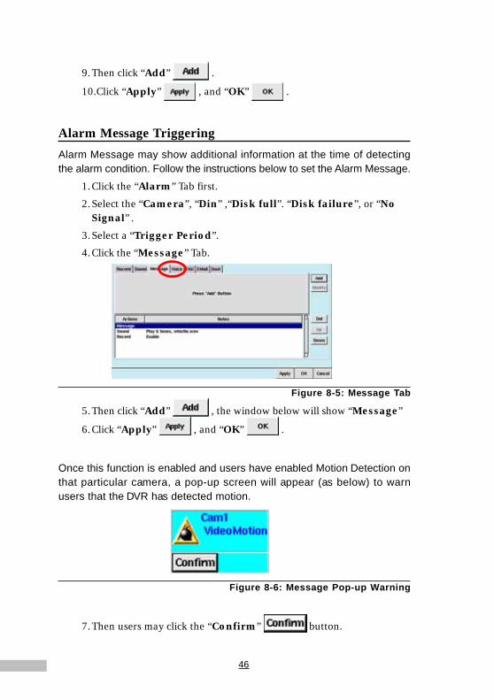
Alarm Message TriggeringAlarm Message may show additional information at the time of detectingthe alarm condition. Follow the instructions below to set the Alarm Message.
1.Click the “Alarm” Tab first.
2.Select the “Camera”, “Din” ,“Disk full”. “Disk failure”, or “NoSignal” .
3.Select a “Trigger Period”.
4.Click the “Message” Tab.
Figure 8-5: Message Tab
5.Then click “Add” , the window below will show “Message”
6.Click “Apply” , and “OK” .
Once this function is enabled and users have enabled Motion Detection onthat particular camera, a pop-up screen will appear (as below) to warnusers that the DVR has detected motion.
Figure 8-6: Message Pop-up Warning
7.Then users may click the “Confirm” button.
47
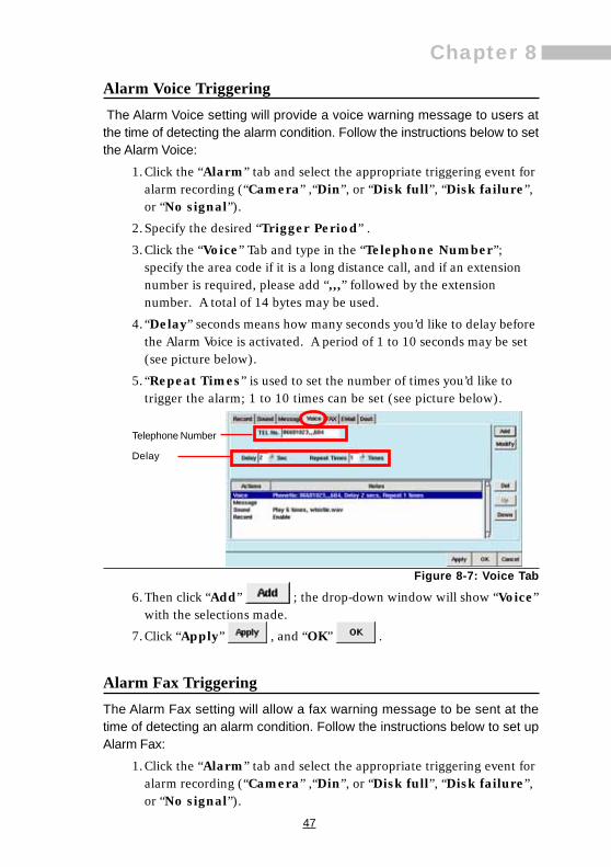
Chapter 8Alarm Voice Triggering The Alarm Voice setting will provide a voice warning message to users atthe time of detecting the alarm condition. Follow the instructions below to setthe Alarm Voice:
1.Click the “Alarm” tab and select the appropriate triggering event foralarm recording (“Camera” ,“Din”, or “Disk full”, “Disk failure”,or “No signal”).
2.Specify the desired “Trigger Period” .
3.Click the “Voice” Tab and type in the “Telephone Number”;specify the area code if it is a long distance call, and if an extensionnumber is required, please add “,,,” followed by the extensionnumber. A total of 14 bytes may be used.
4. “Delay” seconds means how many seconds you’d like to delay beforethe Alarm Voice is activated. A period of 1 to 10 seconds may be set(see picture below).
5. “Repeat Times” is used to set the number of times you’d like totrigger the alarm; 1 to 10 times can be set (see picture below).
Figure 8-7: Voice Tab
6.Then click “Add” ; the drop-down window will show “Voice”with the selections made.
7.Click “Apply” , and “OK” .
Alarm Fax TriggeringThe Alarm Fax setting will allow a fax warning message to be sent at thetime of detecting an alarm condition. Follow the instructions below to set upAlarm Fax:
1.Click the “Alarm” tab and select the appropriate triggering event foralarm recording (“Camera” ,“Din”, or “Disk full”, “Disk failure”,or “No signal”).
Telephone Number
Delay

48
2.Select a “Trigger Period” .
3.Click the “Fax” Tab
4.Type in the “Fax Number”; if it is along distance call, please add thearea code..
5.Choose from the “Send” drop-down list how many pictures you’dlike to fax; 1 to 30 pictures may be chosen (see picture below).
Figure 8-8: Fax Tab
6.Then click “Add” , and the window below will show “Fax”with the selections made.
7.Click “Apply” , and “OK” .
Alarm Email TriggeringAlarm email may email a warning message at the time of detecting an alarmcondition. Follow the instructions below to set up Alarm email:
1.Click the “Alarm” Tab.
2.Select the “Camera”, “Din”, “Disk full”, “Disk failure” or “nosignal” .
3. Specify the desired “Trigger Period” .
4.Click the “Email” tab.
Figure 8-9: Email Tab

49
Chapter 85.Type in the appropriate email address. An additional email address
may be specified in “CC”.
6.Adjust the “Send” parameter as desired to specify the number ofseconds of video you’d like to send in the email; a value of from 1 to 5seconds may be chosen, and the default value is 2 seconds .
7. If you click “Attach playback program”, you can attach to theemail a playback program of up to 1.78MB, so that the video may beplayed by the email recipient(s). If the recipients have alreadydownloaded the playback program file, you do not need to choosethis option again.
8.Then click “Add” , and the window below will show“EMAIL” with the selections made.
9.Click “Apply” , and “OK” .
Alarm Digital Output TriggeringAlarm Digital Output may activate the digital output at the time of detectingalarm. Follow the instructions to set the Digital Output.
1. Click the “Alarm” Tab.
2.Select the “Camera” .
3.Select a “Trigger Period”.
4.Click the “Dout” Tab
Figure 8-10: Output Port Tab
5.Select an Dout.
6.Tick off “Enable / Not-Enable”, the icon with a tick is “Enable”.
50
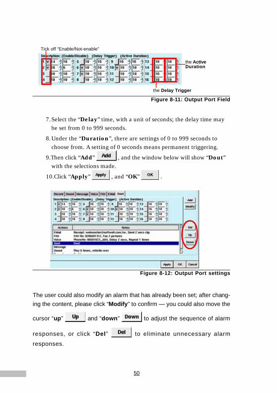
Figure 8-11: Output Port Field
7.Select the “Delay” time, with a unit of seconds; the delay time maybe set from 0 to 999 seconds.
8.Under the “Duration”, there are settings of 0 to 999 seconds tochoose from. A setting of 0 seconds means permanent triggering.
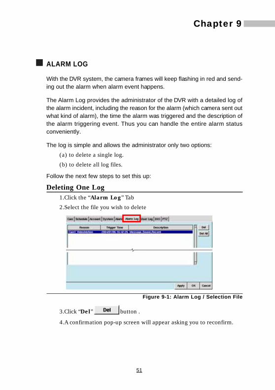
9.Then click “Add” , and the window below will show “Dout”with the selections made.
10.Click “Apply” , and “OK” .
Figure 8-12: Output Port settings
The user could also modify an alarm that has already been set; after chang-ing the content, please click “Modify” to confirm — you could also move the
cursor “up” and “down” to adjust the sequence of alarm
responses, or click “Del” to eliminate unnecessary alarm
responses.
Tick off “Enable/Not-enable”
the Delay Trigger
the ActiveDuration
51
Chapter 9Chapter 9
ALARM LOG
With the DVR system, the camera frames will keep flashing in red and send-ing out the alarm when alarm event happens.
The Alarm Log provides the administrator of the DVR with a detailed log ofthe alarm incident, including the reason for the alarm (which camera sent outwhat kind of alarm), the time the alarm was triggered and the description ofthe alarm triggering event. Thus you can handle the entire alarm statusconveniently.
The log is simple and allows the administrator only two options:(a) to delete a single log.
(b) to delete all log files.
Follow the next few steps to set this up:
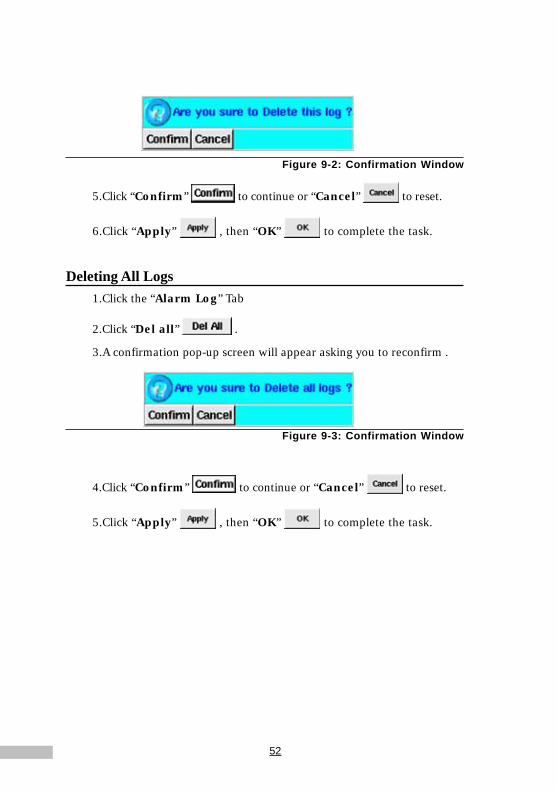
Deleting One Log1.Click the “Alarm Log” Tab
2.Select the file you wish to delete
Figure 9-1: Alarm Log / Selection File
3.Click “Del” button .
4.A confirmation pop-up screen will appear asking you to reconfirm.
52
Figure 9-2: Confirmation Window
5.Click “Confirm” to continue or “Cancel” to reset.
6.Click “Apply” , then “OK” to complete the task.
Deleting All Logs1.Click the “Alarm Log” Tab
2.Click “Del all” .
3.A confirmation pop-up screen will appear asking you to reconfirm .
Figure 9-3: Confirmation Window
4.Click “Confirm” to continue or “Cancel” to reset.
5.Click “Apply” , then “OK” to complete the task.
53
Chapter 10Chapter 10
USER LOG
The User Log provides the administrator of the DVR to monitor all users thathave accessed the DVR. This database tells the administrator whether theusers accessed the system locally or remotely, how long the users werelogged on, and what their IP addresses were. This is only a user log; theinformation cannot be changed. Information in this log can only be deleted,or else the entire log file can be deleted. Follow these few steps to deletefiles:
Deleting One Log
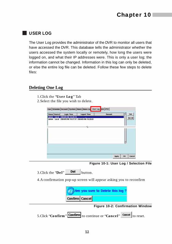
1.Click the “User Log” Tab2.Select the file you wish to delete.
Figure 10-1: User Log / Selection File
3.Click the “Del” button.
4.A confirmation pop-up screen will appear asking you to reconfirm
Figure 10-2: Confirmation Window
5.Click “Confirm” to continue or “Cancel” to reset.

54
6.Click “Apply” , then “OK” to complete the task.
Deleting All Logs1.Click the “User Log” Tab.
2.Click “Del all” .
3.A confirmation pop-up screen will appear asking you to reconfirm.
Figure 10-3: Confirmation Window
4.Click “Confirm” to continue or “Cancel” to reset.
5.Click “Apply” , then “OK” to complete the task.
55
Chapter 11Chapter 11
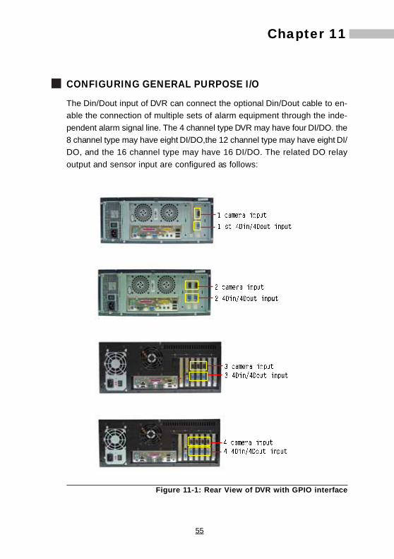
CONFIGURING GENERAL PURPOSE I/O
The Din/Dout input of DVR can connect the optional Din/Dout cable to en-able the connection of multiple sets of alarm equipment through the inde-pendent alarm signal line. The 4 channel type DVR may have four DI/DO. the8 channel type may have eight DI/DO,the 12 channel type may have eight DI/DO, and the 16 channel type may have 16 DI/DO. The related DO relayoutput and sensor input are configured as follows:
Figure 11-1: Rear View of DVR with GPIO interface

56
Figure 11-2 Pin definitions
Click "DI/DO" in Settings to set related functions
Figure 11-3: DIO setting
Input SettingsEach camera has a corresponding sensor input. This sensor input must be ofthe dry contact closure type, with a voltage of less than 5V.
Depending on their attributes, the sensors can be set to Normal Open (NO)or Normal Closed (NC) according to the users’ application requirements.
Normal open, NOWhen the sensor is of the NO type, DI is connected to the NO connec-tion of the sensor and GND is connected to the COM connection of thesensor. When the alarm is triggered, the circuit connected to thealarm sensor input of the DVR will be closed.
57
Chapter 11
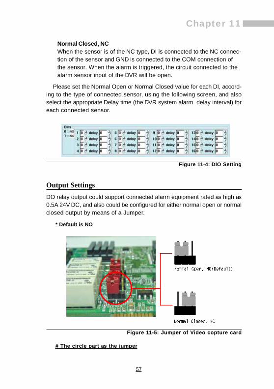
Normal Closed, NCWhen the sensor is of the NC type, DI is connected to the NC connec-tion of the sensor and GND is connected to the COM connection ofthe sensor. When the alarm is triggered, the circuit connected to thealarm sensor input of the DVR will be open.
Please set the Normal Open or Normal Closed value for each DI, accord-ing to the type of connected sensor, using the following screen, and alsoselect the appropriate Delay time (the DVR system alarm delay interval) foreach connected sensor.
Figure 11-4: DIO Setting
Output SettingsDO relay output could support connected alarm equipment rated as high as0.5A 24V DC, and also could be configured for either normal open or normalclosed output by means of a Jumper.
* Default is NO
Figure 11-5: Jumper of Video copture card
# The circle part as the jumper

58
Normal open, NO
If the DO relay output is set to be normally open, when an alarm istriggered, The DO relay output of the DVR will transition from open toclosed.
Normal Closed, NC
If the DO relay output is set to be normally closed, when an alarm istriggered, The DO relay output of the DVR will transition from closed toopen.
The user can specify the connection point number and also select a closedor open condition under the “Manual Dout Control”, in order to test thefunctionality of any given connected alarm device.
Figure 11-6: Manual Dout Control setting

59
Chapter 12
PAN TILT ZOOM
Pan Tilt Zoom (PTZ) provides the administrator of the DVR with the ability toconfigure and monitor all PTZ cameras that are connected to the DVR. TheDVR can be configured with multiple PTZ cameras. Currently, the systemsupports the following PTZ models:
1. Lilin Protocol: PIH-7000, PIH-7600, PIH-7625
2. Vido Protocol: CD-55
3. Pelco Protocol: Pelco-D and Pelco-P(Pelco Spectra III series)
4. SAE Protocol: CD-55H.CD-56,CD-65
5. PANASONIC Protocol: only support for WV-CS850, WV-CS854(Traditional Protocol)
6. Dynacolor Protocol: D7722, D77HO
7. MD-Nicecam: MP1000, MD1800
8. Katatel-312 Protocol
The user should contact their dealer for information regarding which PTZcameras they can provide at present. This chapter shows users how to con-figure a PTZ camera that is compatible with the DVR.
1.Click the “PTZ” Tab.
Figure 12-1: PTZ Tab
Chapter 12
60
On the left side of the window you will see a live view from your PTZcamera. This allows you to configure and see a “live” feed so you canadjust the system to your requirements.
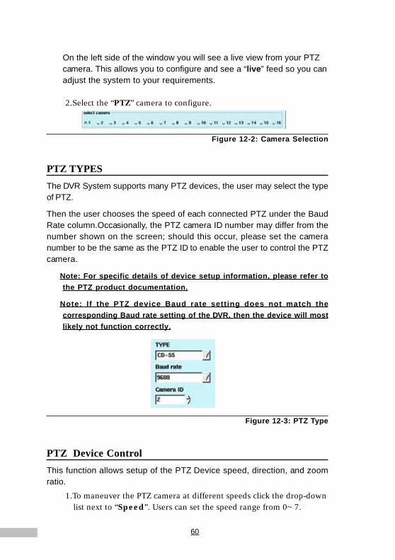
2.Select the “PTZ” camera to configure.
Figure 12-2: Camera Selection
PTZ TYPESThe DVR System supports many PTZ devices, the user may select the typeof PTZ.
Then the user chooses the speed of each connected PTZ under the BaudRate column.Occasionally, the PTZ camera ID number may differ from thenumber shown on the screen; should this occur, please set the cameranumber to be the same as the PTZ ID to enable the user to control the PTZcamera.
Note: For specific details of device setup information, please refer tothe PTZ product documentation.
Note: If the PTZ device Baud rate setting does not match thecorresponding Baud rate setting of the DVR, then the device will mostlikely not function correctly.
Figure 12-3: PTZ Type
PTZ Device ControlThis function allows setup of the PTZ Device speed, direction, and zoomratio.
1.To maneuver the PTZ camera at different speeds click the drop-downlist next to “Speed”. Users can set the speed range from 0~7.

61
Chapter 122.Using the Dome controls at the bottom left of the “PTZ” window,
users can configure their PTZ cameras to move left , right ,
up , and down .
3.If your DVR system is set up to use a PTZ camera, you can zoom the
camera in or out by clicking to zoom in, and to zoom out.
Figure 12-4: Dome Settings, Focus, Iris
If you are not familiar with the DVR system or do not know how to properlycontrol a PTZ camera, please try to follow the steps introduced above, whileobserving the resultant changes to the screen output. Once you understandhow to control the PTZ device, then you could start to learn the followingadditional PTZ device functionality.
FocusWhen connecting a PTZ camera to your Digital Video Recorder, you havethe option to focus in on the picture. Use to focus-in, to focus-out,an d t o h a v e t h e c am e r a a u t o m a t i c a l l y ad j u s t e d .
IrisWhen connecting a PTZ camera to your Digital Video Recorder, you havethe option to adjust the iris on the camera. Use to make the iris smaller,or use to make the iris bigger.
Note: Some of the PTZs setup as Auto by default. It's iris can't beadjusted manually. Pls refer to the PTZ product documentation for thedetails.

62
Preset SetupOnce you have become familiar with these settings and defined your de-sired parameters, you are ready to preset your PTZ camera. The DigitalVideo Recorder provides users with 128 preset positional orientation pointsfor each connected PTZ device. For each preset point, users can adjust thespeed and duration interval for the camera.
1.Specify the preset point number (from 0 to 128): 0 means NULL,that’s NO MOTION).
2.Set the Speed of the PTZ camera adjustment (range from 0 to 7),then adjust the Dome orientation.
Figure 12-5: Preset Setup
3.Specify the “Speed” within the preset point field (this ranges from 0degree per second to 255 degrees per second) and the duration“Time” (range from 0 to 255 seconds) to make adjustments topreset speed and duration time for the PTZ camera.
4.Once complete, click the “Save” button .
5.To view any of the preset camera pictures in later time, just insertthe appropriate camera number in the “Preset” field.
6.Click “Clear one preset” to delete a presetpoint.
7.Click “Clear all preset” to delete all presets.
Grouping PresetsThe Digital Video Recorder gives users the option to set up to 128 presets.Of the 128 presets, presets 1 to 4 make up Group One, presets 5 to 8 makeup Group Two, presets 9 to 12 make up Group Three and presets 13 to 16make up Group Four. The remaining presets are only used to view pictures
preset points
63
Chapter 12in particular directions more conveniently.
The main purpose of Group presets is to allow the user to Auto Pan to spe-cific preset points.
When the presets are complete, follow these instructions to Auto Pan thePTZ cameras according to the presets in the groups:
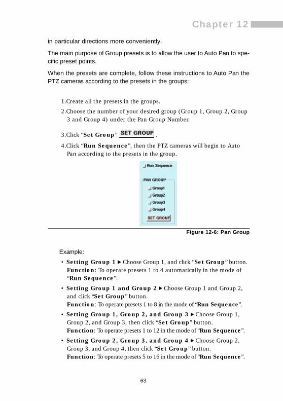
1.Create all the presets in the groups.
2.Choose the number of your desired group (Group 1, Group 2, Group3 and Group 4) under the Pan Group Number.
3.Click “Set Group” .
4.Click “Run Sequence”, then the PTZ cameras will begin to AutoPan according to the presets in the group.
Figure 12-6: Pan Group
Example:• Setting Group 1 Choose Group 1, and click “Set Group” button.
Function: To operate presets 1 to 4 automatically in the mode of“Run Sequence”.
• Setting Group 1 and Group 2 Choose Group 1 and Group 2,and click “Set Group” button.Function: To operate presets 1 to 8 in the mode of “Run Sequence”.
• Setting Group 1, Group 2, and Group 3 Choose Group 1,Group 2, and Group 3, then click “Set Group” button.Function: To operate presets 1 to 12 in the mode of “Run Sequence”.
• Setting Group 2, Group 3, and Group 4 Choose Group 2,Group 3, and Group 4, then click “Set Group” button.Function: To operate presets 5 to 16 in the mode of “Run Sequence”.
64
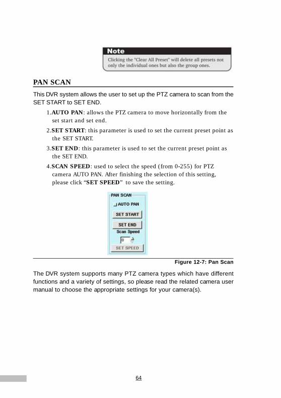
PAN SCANThis DVR system allows the user to set up the PTZ camera to scan from theSET START to SET END.
1.AUTO PAN: allows the PTZ camera to move horizontally from theset start and set end.
2.SET START: this parameter is used to set the current preset point asthe SET START.
3.SET END: this parameter is used to set the current preset point asthe SET END.
4.SCAN SPEED: used to select the speed (from 0-255) for PTZcamera AUTO PAN. After finishing the selection of this setting,please click “SET SPEED” to save the setting.
Figure 12-7: Pan Scan
The DVR system supports many PTZ camera types which have differentfunctions and a variety of settings, so please read the related camera usermanual to choose the appropriate settings for your camera(s).

65
Chapter 13Chapter 13
PLAYBACK
One of the most important features of any Digital Video Recorder is playback.Playback allows users to view recorded data, as the system is recording oras users view live data remotely. The features within “Playback” are: Blur,Snapshot, Export, Tag, File, Alarm, Fast Forward, Slow Motion, Skip & Rewind.All of these features are covered later in this chapter. Let’s first take a look athow we can review playback.
To view Playback click the “Playback” Icon ---------------------------------
A pop-up database window will appear giving you the choice of selecting afile. Selecting by Date, Time and Camera, or by checking the list of all files,you are able to choose record files. At the bottom of the screen you willnotice a set of icons. These icons will help later when using the playbackimage.
Figure 13-1: Playback Screen
Understanding the Recorded DatabaseLet’s take a closer look at the options in the database window before we viewplayback images.

66
Figure 13-2: Pop-up Database Screen
1.Calendar Search: Clicking the “Calendar” button, users are ableto search the desired record files depending on the selected date.
2.Time Search: Clicking the “Time Search” button allowsusers to select a specific time in which they would like to view thefiles.
3.Camera Search: Select the camera whose recording files you wantto playback; you could choose more than one camera if desired.
4.Select All: click “ALL” to choose all cameras.
5.Reset: click “reset” to clear the current data, and reset the new filesyou choose.
6.Other path: click “other path” to choose the recording files under“other path”.
7.Back up: choose the file you need to back up and click “Backup” toback up files.
NOTE: Press <Shift> and mouse's left button at the same time, you canchoose multipe files.
8.Search Button: Click the “Search” button to list all recorded filesin accordance with the selected Date, Time and Camera.
9.List Button: Click this button to display a list of all the recordeddatabase.
10.Open: Click this button to view a selected file.
11.Cancel Button: Cancel all actions.
time search

67
Chapter 13Understanding the Bottom Toolbar
The Bottom Toolbar appears only when you click the playback icon. Beforea recorded file is selected, the bottom toolbar will be hidden (disabled).Once a recorded file is selected, the toolbar icons will appear (be enabled).Let¡¦s view what each icon means.
Figure 13-3: Bottom Toolbar
Click this icon to exit playback.
If there is a function of NAS in your DVR (It is optional), clickthis icon to enter the video file page to select and playbackfiles in NAS by date, time and camera.
If there is a function of Multiple Playback in your DVR (It isoptional), click this icon to enter the Multiple Playback page.
If there is a function of Audio out (It is optional), click this iconto turn the mute on or off.
Click the directional icons to move the playback images up,down, left, or right.
Click this icon to remove blur, to sharpen or define the image.
Click this icon to blur the image.
Click this image to take a snapshot (one selected frame formthe current video file), and export or print the snapshot image.
Click this image to save an image to disk.
Click this icon to tag an important section of the recorded file.Once the file is tagged, you can go directly back to the relevantplace when you open this tag to review this file.
Click this quick reference icon to enter the recorded databasewindow, you can list the recorded files by date, time, orcamera or, you can list all recorded files, and then select thefile to play.
Click this icon to review the previous file.
Click this icon to rewind play.
Click this icon to pause play, repeat click this icon will play theimage frame by frame.
68
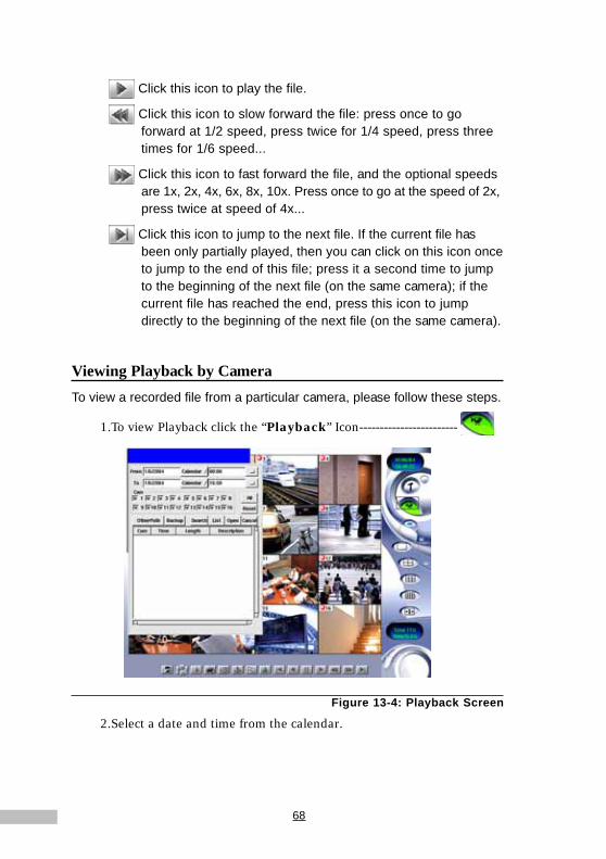
Click this icon to play the file.
Click this icon to slow forward the file: press once to goforward at 1/2 speed, press twice for 1/4 speed, press threetimes for 1/6 speed...
Click this icon to fast forward the file, and the optional speedsare 1x, 2x, 4x, 6x, 8x, 10x. Press once to go at the speed of 2x,press twice at speed of 4x...
Click this icon to jump to the next file. If the current file hasbeen only partially played, then you can click on this icon onceto jump to the end of this file; press it a second time to jumpto the beginning of the next file (on the same camera); if thecurrent file has reached the end, press this icon to jumpdirectly to the beginning of the next file (on the same camera).
Viewing Playback by CameraTo view a recorded file from a particular camera, please follow these steps.
1.To view Playback click the “Playback” Icon------------------------
Figure 13-4: Playback Screen
2.Select a date and time from the calendar.

69
Chapter 13
Figure 13-5: Calendar & Camera Selection
3.Select a camera.
4.Click “Search” , to list the desired files, or click “List” to show all the files.
5.Then the recorded database will be listed on the screen (if the camerais defined with a name, the name will appear in the “Description”field).
Figure 13-6: Recording Database
6.Choose the recorded file to play.
Figure 13-7: Camera Selection

70
7.Double-click the selection or click “Open” . The video from theselected file will appear in the top left-hand corner of the Main Screen.
Figure 13-8: Recorded Data Playback
8.Click “Play” from the Bottom Toolbar
9.Double-click the image to enlarge-----------------
Figure 13-9: Enlarged Image
10.Double-click the image again to enlarge-----------------

71
Chapter 13
Figure 13-10: Full-size Playback Image
11.To reduce the size or go back to the original size, right-click ---
Alarm Recorded PlaybackFollow these steps to view alarm triggered playback images
1.Click the “Alarm” Icon.
2.A database of all the alarm triggered playback files will appear (AlarmLog)
Figure 13-11: Alarm Log
3.Please select the file you want from the alarm video log. Double-clickit or click “Open” . The selected file will appear in front of theMain Screen.

72
4. Click “Play” to view the file.
Figure 13-12: Alarm Triggered File
Tagging Recorded DataAfter opening a file, if some important section has been found in the video,that section can be tagged for later reference. While watching the videoframes, the tagged section can be operated like this:
1.Click the “Tag” button to enter the window.
Figure 13-13: Tag Field
2.Type in the Tag name first.
3.Click the “Insert” button, the information about the Camera, Tagtime, and Description (the camera name) will be added to the systemautomatically and then be listed out.
73
Chapter 13
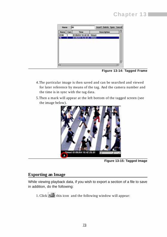
Figure 13-14: Tagged Frame
4.The particular image is then saved and can be searched and viewedfor later reference by means of the tag. And the camera number andthe time is in sync with the tag data.
5.Then a mark will appear at the left bottom of the tagged screen (seethe image below).
Figure 13-15: Tagged Image
Exporting an ImageWhile viewing playback data, if you wish to export a section of a file to savein addition, do the following:
1.Click this icon and the following window will appear:

74
Figure 13-16: Export Image
2.The image highlights the hours, minutes, and seconds. Use the drop-down list to select the time frame when you would like to export.
There are two ways to export:
(1)DVRClick “Export Playback program” to export video with the DVRexport playback program. If you have already downloaded thisplayback program, you do not need to click the “Export Playbackprogram” tab again.
(2)HTML+JPGIf you export the video by choosing this type, you will be able toview the video with a standard browser.
Comparison of the two methods of Video Export
Note1: The installation program for playback program is DvrActiveXSetup.exe, which would be allocated on the same directory of exported data files.When users click on the DvrActiveXSetup.exe, installation will be initiatedautomatically, and will run playback right away
Note2: If your PC already installed the playback program, you can click directlyon the exported data file (.dvr) for playback
DVR (MPEG-4) HTML+JPG a. Uses the DVR’s unique playback
program, the video will not be trancscoded and is more clearer.
a. the image can be viewed in a standard browser.
b. The first time the program is used You need to export the playback program.
b. due to the transcoding, the image is not so clear.

75
Chapter 13Note3: The rules on naming the exported data files would be asC1_20030306_120000_60.dvr(DVR host site data exporting) orC1_0306_120000_60.dvr(remote site data exporting), meaning cameraone, and the recording activities beginning by 2003/03/06 12:00:00, andthe length of the recording file is 60 seconds
3.Then click “NEXT” to continue.
4.The DVR then asks you to choose the media and the destination forthe file to and the name of the file. Once complete, click “OK”
to confirm.(If the space is not big enough for the export file,the system will inform you beforehand and stop the export mode)
Figure 13-17: Export Image (2)
Smoothing an ImageThe smoothness and sharpness of an image can be adjusted in the DVR.When an image is unclear or if it is important to clarify the image, you canuse one of two functions.
Figure 13-18: Sharp Image
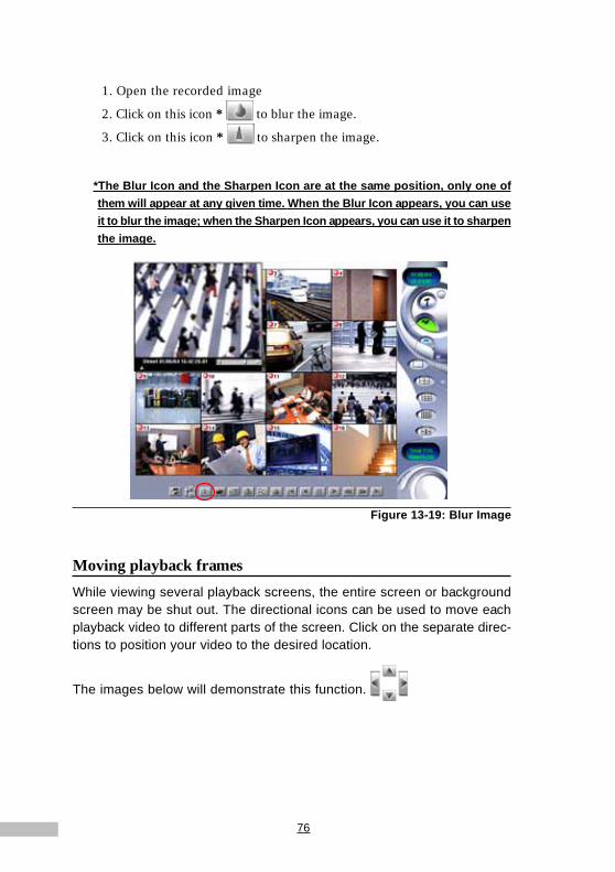
76
1. Open the recorded image
2. Click on this icon * to blur the image.
3. Click on this icon * to sharpen the image.
*The Blur Icon and the Sharpen Icon are at the same position, only one ofthem will appear at any given time. When the Blur Icon appears, you can useit to blur the image; when the Sharpen Icon appears, you can use it to sharpenthe image.
Figure 13-19: Blur Image
Moving playback framesWhile viewing several playback screens, the entire screen or backgroundscreen may be shut out. The directional icons can be used to move eachplayback video to different parts of the screen. Click on the separate direc-tions to position your video to the desired location.
The images below will demonstrate this function.
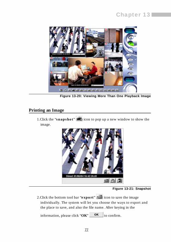
77
Chapter 13
Figure 13-20: Viewing More Than One Playback Image
Printing an Image
1.Click the “snapshot” icon to pop up a new window to show theimage.
Figure 13-21: Snapshot
2.Click the bottom tool bar “export” icon to save the imageindividually. The system will let you choose the ways to export andthe place to save, and also the file name. After keying in the
information, please click “OK” to confirm.
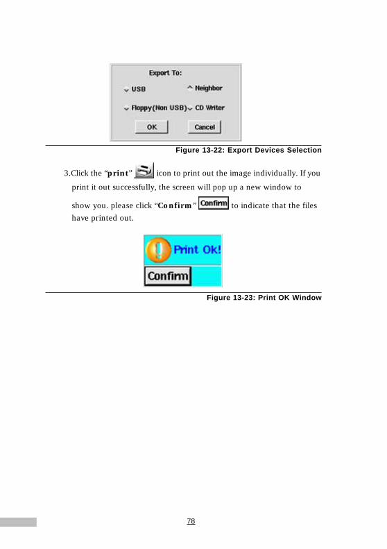
78
Figure 13-22: Export Devices Selection
3.Click the “print” icon to print out the image individually. If you
print it out successfully, the screen will pop up a new window to
show you. please click “Confirm” to indicate that the fileshave printed out.
Figure 13-23: Print OK Window

79
Chapter 14Chapter 14
REMOTE SURVEILLANCE
The DVR allows users to view the cameras connected to the DVR and therecorded file playback remotely through browsers. The DVR system is ableto provide users with all functions available on the Host port. Once you haveset up the local LAN and Internet functionality from the System Window, youare able to easily and conveniently operate your Digital Video Recorderremotely.
1.Click the “Setup” icon from the Main Screen of the DVR system ---
2.Click the “System” Tab.
Figure 14-1: System Tab Screen for LAN Identification
3.Identify your IP address.
4.Open your browser.
5.In the address field enter the IP address.
6.Hit “Enter”. The DVR remote logon window will appear.
7.Under Name enter admin (the default Account for Administrator).
8.Under Password enter admin (the default password).
9.Click Login.
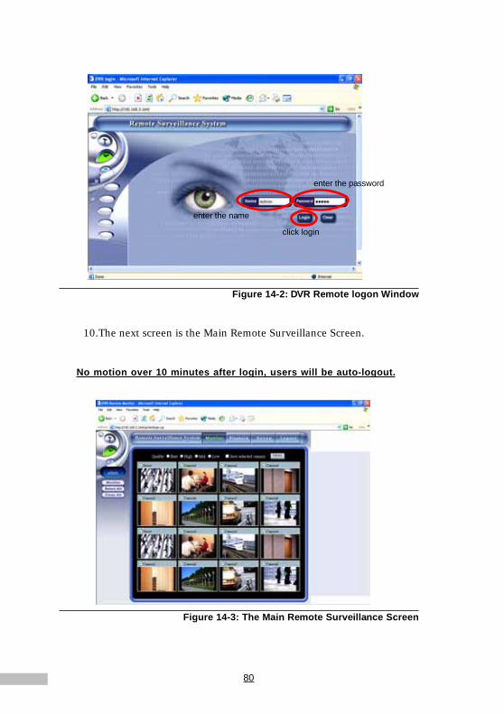
80
Figure 14-2: DVR Remote logon Window
10.The next screen is the Main Remote Surveillance Screen.
No motion over 10 minutes after login, users will be auto-logout.
Figure 14-3: The Main Remote Surveillance Screen
enter the name
enter the password
click login
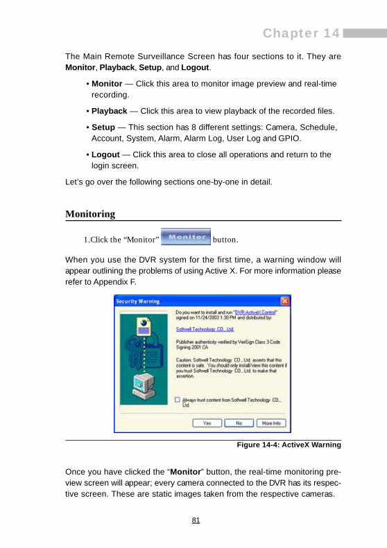
81
Chapter 14The Main Remote Surveillance Screen has four sections to it. They areMonitor, Playback, Setup, and Logout.
• Monitor — Click this area to monitor image preview and real-timerecording.
• Playback — Click this area to view playback of the recorded files.
• Setup — This section has 8 different settings: Camera, Schedule,Account, System, Alarm, Alarm Log, User Log and GPIO.
• Logout — Click this area to close all operations and return to thelogin screen.
Let’s go over the following sections one-by-one in detail.
Monitoring
1.Click the “Monitor” button.
When you use the DVR system for the first time, a warning window willappear outlining the problems of using Active X. For more information pleaserefer to Appendix F.
Figure 14-4: ActiveX Warning
Once you have clicked the “Monitor” button, the real-time monitoring pre-view screen will appear; every camera connected to the DVR has its respec-tive screen. These are static images taken from the respective cameras.

82
Figure 14-5: Remote Monitor Screen - Remote Monitor
This screen provides a view of the static preview images from all cameras bydefault. The user may select which camera’s video to monitor as live video.This screen also displays the name of the current user.
2.Click “Select All” to view monitoring screens fromall cameras in the new window.
Four degrees of image quality may be selected: Low, Mid, High, Best.
Figure 14-6: Image Quality Field
3.Click first the left button “Clear All” .
4.Then Check the camera you want to view.
to show logininguser’s name
Monitor image qualityselection
Save the selectedcameras
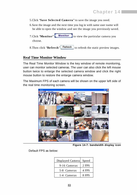
83
Chapter 145.Click “Save Selected Camera” to save the image you need.
6.Save the image and the next time you log in with same user name willbe able to open the window and see the image you previously saved.
7.Click “Monitor” to view the particular camera youchoose.
8.Then click “Refresh” to refresh the static preview images.
Real Time Monitor WindowThe Real Time Monitor Window is the key window of remote monitoring,user can monitor selected cameras. The user can also click the left mousebutton twice to enlarge the selected camera window and click the rightmouse button to restore the enlarge camera window.
The Maximum FPS of each camera will be shown on the upper left side ofthe real time monitoring screen.
Figure 14-7: bandwidth display icon
Default FPS as below:
Displayed Camera Speed
9-16 Cameras 2 FPS
5-8 Cameras 4 FPS
1-4 Cameras 8 FPS

84
Click < or > to adjust the Max. speed (0-30 FPS) as below:
Figure 14-8: Adjust maximum display speed
Click icon to export images to HDD or print it out via printer: (as below)
Figure 14-9: Focused camera image export (1)

85
Chapter 14
Figure 14-10: Focused camera image export (2)
as the icon for displaying bandwidth, click it to display the bandwidth,click again to hide the information
Figure 14-11: show the bandwidth
The second icon on the upper right side of the real time monitor windowmay be used to minimize the window.
Figure 14-12: Minimize real time monitor window
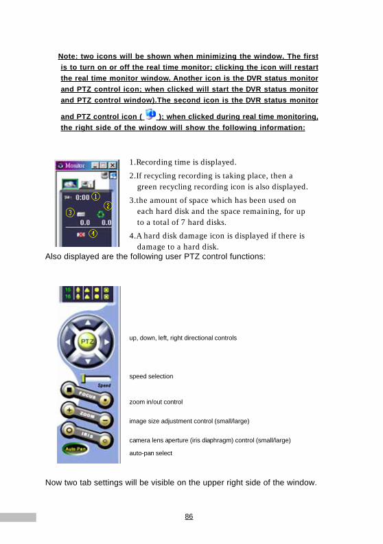
86
Note: two icons will be shown when minimizing the window. The firstis to turn on or off the real time monitor; clicking the icon will restartthe real time monitor window. Another icon is the DVR status monitorand PTZ control icon; when clicked will start the DVR status monitorand PTZ control window).The second icon is the DVR status monitor
and PTZ control icon ( ); when clicked during real time monitoring,the right side of the window will show the following information:
Also displayed are the following user PTZ control functions:
Now two tab settings will be visible on the upper right side of the window.
1.Recording time is displayed.
2.If recycling recording is taking place, then agreen recycling recording icon is also displayed.
3.the amount of space which has been used oneach hard disk and the space remaining, for upto a total of 7 hard disks.
4.A hard disk damage icon is displayed if there isdamage to a hard disk.
up, down, left, right directional controls
speed selection
zoom in/out control
image size adjustment control (small/large)
camera lens aperture (iris diaphragm) control (small/large)
auto-pan select
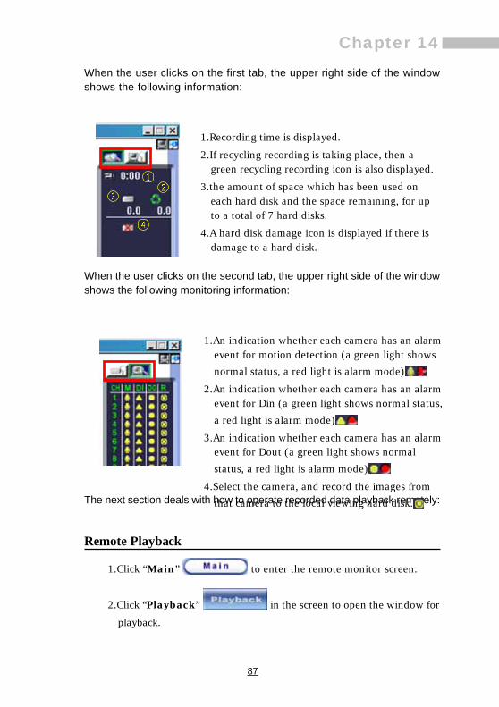
87
Chapter 14When the user clicks on the first tab, the upper right side of the windowshows the following information:
When the user clicks on the second tab, the upper right side of the windowshows the following monitoring information:
The next section deals with how to operate recorded data playback remotely:
Remote Playback
1.Click “Main” to enter the remote monitor screen.
2.Click “Playback” in the screen to open the window for
playback.
1.Recording time is displayed.
2.If recycling recording is taking place, then agreen recycling recording icon is also displayed.
3.the amount of space which has been used oneach hard disk and the space remaining, for upto a total of 7 hard disks.
4.A hard disk damage icon is displayed if there isdamage to a hard disk.
1.An indication whether each camera has an alarmevent for motion detection (a green light shows
normal status, a red light is alarm mode)
2.An indication whether each camera has an alarmevent for Din (a green light shows normal status,
a red light is alarm mode)
3.An indication whether each camera has an alarmevent for Dout (a green light shows normal
status, a red light is alarm mode)
4.Select the camera, and record the images from
that camera to the local viewing hard disk.

88
Figure 14-13: Understanding the Playback Toolbar
Understanding the Playback ToolbarThe playback sidebar gives users the freedom to manipulate the image totheir benefit. Let’s take a closer look at these icons:
1.Play Button: Click this button to play the file
2.Reverse Button: Click this button to rewind the played image
3.Pause Button: Click this button to stop playing for a pause
4.Last Section Button: Click this button to rewind to last section
5.Next Section Button: Click this button to go to the next frame
6.File Button: Click this button to choose the file you want to view
7.Alarm File Button: Click this button to find an alarm recorded file
8.Tag File Button: Click this button to find a file by its tag
9.Snapshot Button: Click this button to take a snapshot and print it out
10.Export Button: Click it to export and save an image to outputdevices
11.Tag Button: Click this button to mark a recorded file
12.NAS: If there are video data back up to NAS, then you can click it toplayback the back up clips in NAS.
13.Speed: 8x,6x,4x,2x,1x, 1/2x, 1/4x, 1/6x, 1/8x and one frame
14.Resolution: Click this button to select the size of the screen; theoptions are 320x240, 480x360, 640x480 etc.

89
Chapter 14
The first time you enter the Record Playback mode of the remote monitorsystem, a warning window will appear concerning the problems associatedwith using ActiveX. For more information please refer to Appendix F.
Figure 14-14: The Remote Playback Screen
There is a horizontal scroll bar on the bottom of the playing window, whichfacilitates users in searching films quickly. You may press and hold the leftmouse button on it and drag it from left to right until you find the video imagethat you need.
Playback by File
You may click “Playback” to view the files remotely:
1.Once you have clicked the “File” icon,.
2.A new pop-up window will appear allowing you to select the camera,
and the time you wish to preview.
Speed Screen
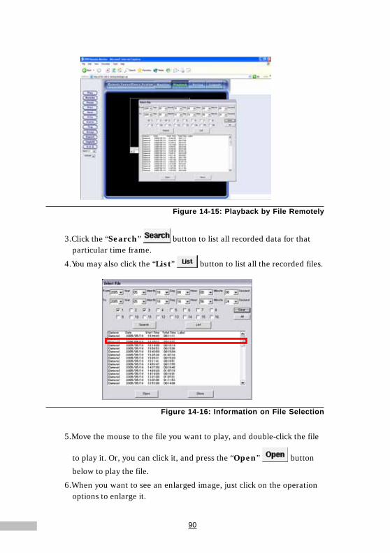
90
Figure 14-15: Playback by File Remotely
3.Click the “Search” button to list all recorded data for thatparticular time frame.
4.You may also click the “List” button to list all the recorded files.
Figure 14-16: Information on File Selection
5.Move the mouse to the file you want to play, and double-click the file
to play it. Or, you can click it, and press the “Open” button
below to play the file.
6.When you want to see an enlarged image, just click on the operationoptions to enlarge it.

91
Chapter 14
Figure 14-17: Remote Playback - Enlarged Image
Alarm File“Alarm File” allows users to see the time and camera numbers concernedwith an alarm, and all the alarm files can be deleted.
1.Click “Alarm”.
2.Select one alarm file, click “Open” to play it.
3.Click the “Delete” button to delete one alarm file.
Figure 14-18: Alarm File
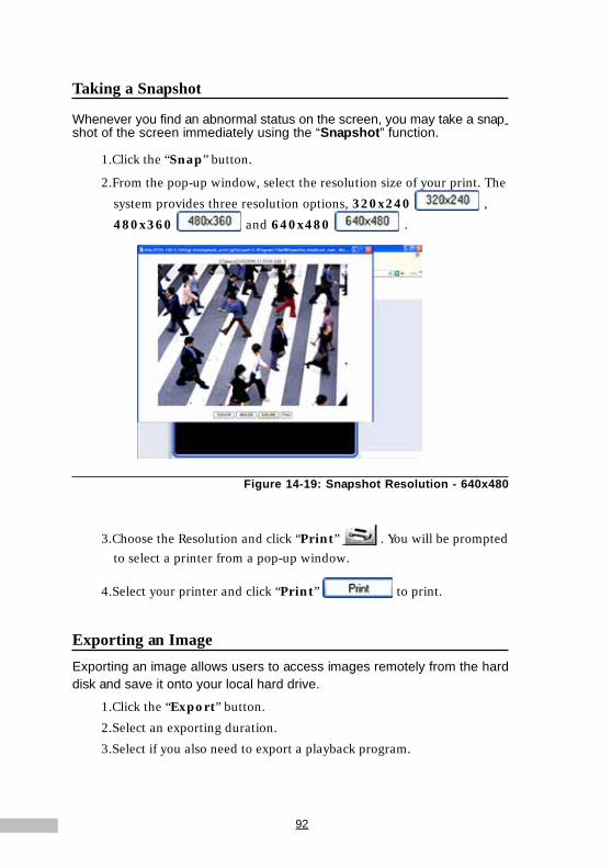
92
Taking a Snapshot
Whenever you find an abnormal status on the screen, you may take a snap-shot of the screen immediately using the “Snapshot” function.
1.Click the “Snap” button.
2.From the pop-up window, select the resolution size of your print. The
system provides three resolution options, 320x240 ,
480x360 and 640x480 .
Figure 14-19: Snapshot Resolution - 640x480
3.Choose the Resolution and click “Print” . You will be promptedto select a printer from a pop-up window.
4.Select your printer and click “Print” to print.
Exporting an ImageExporting an image allows users to access images remotely from the harddisk and save it onto your local hard drive.
1.Click the “Export” button.
2.Select an exporting duration.
3.Select if you also need to export a playback program.

93
Chapter 14
Figure 14-20: Export Duration
4.Click “Export” to choose path for saving the file and enter the file
name, then click “Save” to save this file to disk.
* If the time for exporting is a little long, please wait for a while patiently.
Inserting a TagInserting a tag allows users to mark an important section of a file specially.Once it’s opened, the tagged file will be played from the marked place. Afteradding the tagged files, click the “Tag” in the file options; a pop-up windowwill list all the tagged files.
The following tells how to produce a tagged file:1.Click the “Tagadd” button.
2.After entering the Tag Name, click the “OK” button.
Figure 14-21: Export Duration

94
3.Click the “Tag” on the Playback Side Toolbar.
4.Select the file you wish to view.
5.Click Open (to view the image) or Delete to discard a useless Tag.
Figure 14-22: Tag Window
NASClick this button, you can playback the video clips that back up in NAS.
Configuring Setup RemotelyThe functions for remote setup are basically the same as those used locally.The following instructions outline this in detail.
1.On the Main Remote Screen click “Setup” .
2.The next screen is the Camera setup window.

95
Chapter 14
Figure 14-23: Main Remote Screen - Setup Screen
Remote Camera ConfigurationWhen configuring cameras remotely for the first time, please install therelated Active-X Object , according to the information provided in Appendix F.All remote functionality is set up similarly to the local machine. The majordifference is the way the interface looks. On the left side of the viewing areaare the function keys for setup. Clicking any of the keys will lead you into therelated setup screen. Then you can choose the camera and set relatedparameters on the right side of the viewing area.
\
Figure 14-24: Remote Camera Configuring Screen

96
Additionally, in the camera configuring screen users may have thefollowing selections:1.Cameras
2.Activate the camera and the camera name
3.Status Display — the Camera Number, the Date and the Time willbe displayed on the monitoring screen on the left
Figure 14-25: Remote Camera Configuration(1)
4.Character Color — the optional colors are Black, Red, Green, Blueand White
NOTE: It will change the text and background color of DVR site, not yourbrowser site.
5.Background Color — the optional colors are Black, Red, Green,Blue and White
6.Recording Mode — there are 3 modes: No Recording, Recordingand Schedule
7.Hue, Saturation, Brightness, Contrast — Users can adjust thevalue or click to choose the default value (50, 50, 50, 50)
8.Motion Detection Frame Setting —
a. “Hidden Area/Show Area” button: Click this button to hide themotion detection frame that has been drawn, click it again to showthe frame.

97
Chapter 14b. “Draw Area” button : up to 6 motion detection
frames can be drawn.
c. “Clean Area” button .
Figure 14-26: Remote Camera Configuration(2)
9.Speed — Users can select the speed to adjust the direction of thePTZ cameras from 0 to 7
10.Camera Direction — users can use the UP, DOWN, LEFT andRIGHT icons to move the cameras
11.Zoom In button & Zoom Out button
12.Iris — Enlarge Iris button & Reduce Iris button
13.Focus — Nearer Focus button & Further Focus button
14.Auto Pan — check this to make the PTZ cameras circumgyrateautomatically
15.Video Image Quality — there are 4 options: Low, Mid, High,and Best
16.Image Resolution — users may choose from 160x120, 320x240and 640x480
17.Image Format — NTSC (or PAL) format
18.Frame Rate (frame per second) — the frame rate can bechosen from 1 to 30 fps
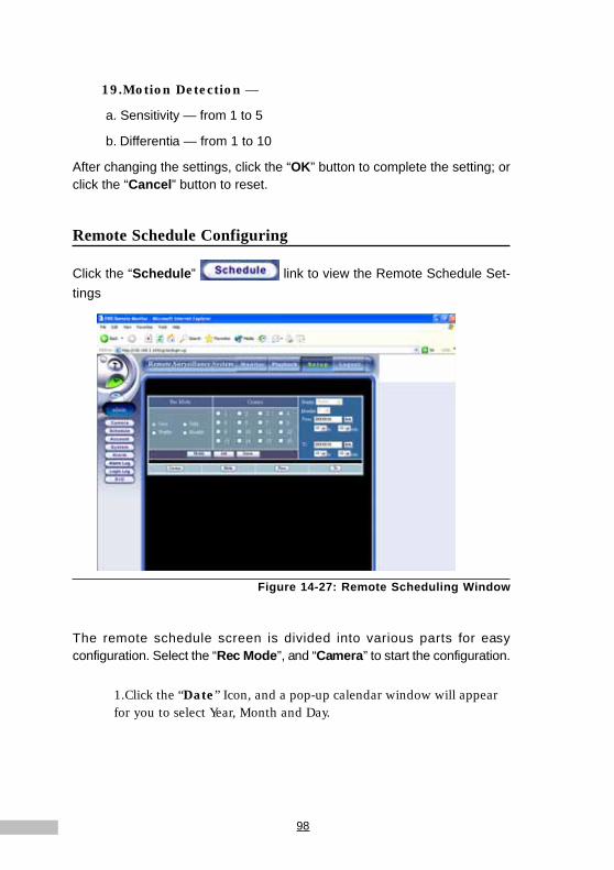
98
19.Motion Detection —
a. Sensitivity — from 1 to 5
b. Differentia — from 1 to 10
After changing the settings, click the “OK” button to complete the setting; orclick the “Cancel” button to reset.
Remote Schedule Configuring
Click the “Schedule” link to view the Remote Schedule Set-tings
Figure 14-27: Remote Scheduling Window
The remote schedule screen is divided into various parts for easyconfiguration. Select the “Rec Mode”, and “Camera” to start the configuration.
1.Click the “Date” Icon, and a pop-up calendar window will appearfor you to select Year, Month and Day.

99
Chapter 14
Figure 14-28: date
2.Then click to choose the right Hour and Minute.
Figure 14-29: Remote Schedule Window
3.Once complete, click “Add” to activate the settings. Afteryou have completed all schedule settings you can view a log of all
changes at the bottom of the window.
Modifying Scheduled Settings
1.Click the data you wish to modify
2.Click the “Modify” button after having changed thescheduled settings.
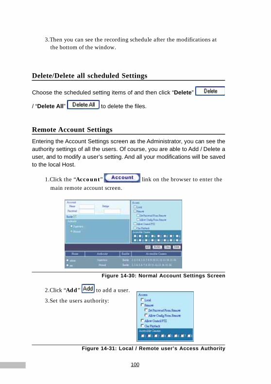
100
3.Then you can see the recording schedule after the modifications atthe bottom of the window.
Delete/Delete all scheduled Settings
Choose the scheduled setting items of and then click “Delete”
/ “Delete All” to delete the files.
Remote Account SettingsEntering the Account Settings screen as the Administrator, you can see theauthority settings of all the users. Of course, you are able to Add / Delete auser, and to modify a user’s setting. And all your modifications will be savedto the local Host.
1.Click the “Account” link on the browser to enter themain remote account screen.
Figure 14-30: Normal Account Settings Screen
2.Click “Add” to add a user.
3.Set the users authority:
Figure 14-31: Local / Remote user’s Access Authority
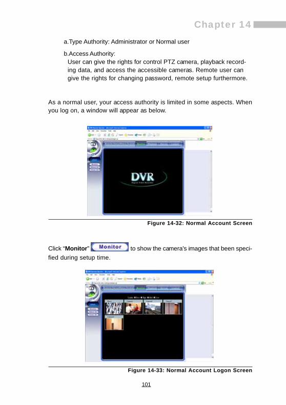
101
Chapter 14a.Type Authority: Administrator or Normal user
b.Access Authority:User can give the rights for control PTZ camera, playback record-ing data, and access the accessible cameras. Remote user cangive the rights for changing password, remote setup furthermore.
As a normal user, your access authority is limited in some aspects. Whenyou log on, a window will appear as below.
Figure 14-32: Normal Account Screen
Click “Monitor” to show the camera's images that been speci-fied during setup time.
Figure 14-33: Normal Account Logon Screen
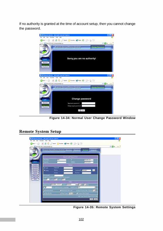
102
If no authority is granted at the time of account setup, then you cannot changethe password.
Figure 14-34: Normal User Change Password Window
Remote System Setup
Figure 14-35: Remote System Settings

103
Chapter 14
1.Click on the “System” link in the browser window toenter the Remote System Settings screen.
In this screen, you are provided with the capability of remote system settings,including:
1.DVR Host and LAN - You are able to see all network settings of theHost, and among them is the IP address that’s relative to remotemonitoring. Once have you entered this IP address in the browserwindow, you can connect to monitor the DVR Host. CAUTION: Donot attempt to change the network settings on the Host from theremote browser, or else communication with the Host will be lost,disabling any further operations.
2.The version number (Version 3.5.4) will be visible in the header.
3.Internet - In this field, you can setup the info regarding to Internetand modem dial-up:
a.DNS Server IP
b.Default Gateway IP
c.The corresponding Virtual Server TCP ports.4.Current System Time, the System Time/Date to be changed.
5.Limot out bandwidth, New HD format, Enable telnetd, Minimize videosize, and the number P frames after I frames.
6.Recycle Recording, Auto Logon, Auto Skip — operations through abrowser are not the same with operations on the Host, so remotemonitoring functions don’t support “Auto Logon” and “AutoSkip”. The setting and modification of these two functions remotelycan only be seen on the Host.
Also, the current status of the hard disk capacity (how much space can beused and has been left) will be shown at the bottom of the screen.
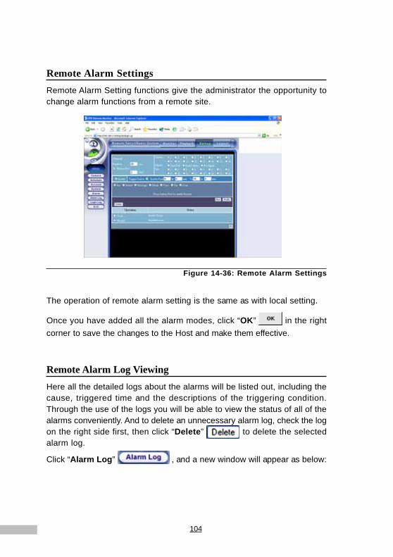
104
Remote Alarm SettingsRemote Alarm Setting functions give the administrator the opportunity tochange alarm functions from a remote site.
Figure 14-36: Remote Alarm Settings
The operation of remote alarm setting is the same as with local setting.
Once you have added all the alarm modes, click “OK” in the rightcorner to save the changes to the Host and make them effective.
Remote Alarm Log ViewingHere all the detailed logs about the alarms will be listed out, including thecause, triggered time and the descriptions of the triggering condition.Through the use of the logs you will be able to view the status of all of thealarms conveniently. And to delete an unnecessary alarm log, check the logon the right side first, then click “Delete” to delete the selectedalarm log.
Click “Alarm Log” , and a new window will appear as below:

105
Chapter 14
Figure 14-37: Remote Alarm Log
If you would like to delete all logs, click in the checkbox next to “Select All”,then press “Delete” , and click “OK” in the pop-upinquiring window.
Figure 14-38: Delete Alarm Log Remotely
Remote User LogAll the users having entered the system will be recorded, with the data notesof their entering and leaving the system. The log shows where the usersentered from and their logon/ logoff time, thus the Administrator is able tosee the current status of the system.
Click the “Login Log” link to view the user log remotely.
Figure 14-39: Remote User Log

106
As previously, check individual logs respectively or click in the checkbox
next to “Select All”, and then click “Delete” to delete unwanted logs.
Remote GPIO Settings
The operation on remote GPIO is the same as with local settings on theDVR host. Once you have added all the GPIO modes, click “Submit”
in the right corner to save the changes to the Host and make themeffective.
Figure 14-40: Remote GPIO Setting Window
After completing all the settings or after using this function, click “Main”
to use other remote functions. Or you can click “Logout”
to leave the remote monitoring system.

107
Appendix A
Backup to NAS (Network Attached Storage)
Backup to NAS(Network Attached Storage)Because the image data of the DVR are larger than text file, plenty storagespace are demanded. NAS can connect to IP network, therefore users canbackup their DVR data to NAS through Internet / LAN at anytime and anywhere.Traditional DAS (Direct Attached System) cannot meet these requirementsanymore.
Steps:
1.Click the ‘’Setup’’ icon on the main screen.
2.Click the ‘’System’’ tab.
3.Click the NAS button to popup the NasSetup windows.
Figure A-1: Click NAS button
4.Enable: Click the ‘’Enable’’ checkbox to enable the NAS feature.
5.Path: Fill in the backup pathname including the IP/Host name ofNAS and the DVR backup folder name on NAS (ex. In above picture,Backup stands for the host name of NAS and nas1 is the name ofDVR backup folder.)
Appendix A

108
Figure A-2: NAS setting
Note: One NAS can connect multiple DVR hosts, in order not to confoundthe back-up data, their folders’ names should be different.
6.User: Fill in the login user account on NAS.
7.Password: Fill in the password for the corresponding user.
8.Overwrite: If you want to recycle your backup NAS storage whenstorage is full, click the ‘’Overwrite’’ checkbox to enable it. Onceoverwrite enabled, NAS will initiate deleting files. The deletion will bebased on the free space lesser or equal to the Lowerbound. Thisprocedure will be continued till the free space is more or equal to theUpperbound.
9.Backup Period: DVR will not keep archiving data to NAS, the ‘’Backup Period’’ is the time interval to make sure NAS synchronizedwith the DVR and backup new data to NAS. (In default, the systemwill auto backup data every 1 minutes.)
10.Volume: “Volume” is the total available space for your DVRbackup.(NAS can backup the data of various DVR hosts, and here werefer to the available space of your DVR can have).
EX: when Volume set up as 10G, Upperbound 400MB, Lowerbound200MB. Once the free space on NAS lesser than 200MB, system willdelete the oldest files, till the free space more than 400MB.)

109
Appendix C
NTP (Network Time Protocol)
NTP (Network Time Protocol)
The Network Time Protocol (NTP) is used to synchronize the clock of DVR toanother reference time source in the network.
Steps:
1.Click the ‘’Setup’’ icon on the main screen.
2.Click the ‘’System’’ tab.
3.Click the ‘’NTP’’ button to popup the NTP setup windows.
Figure B-1:Click NTP to synchronize the clock of DVR
Appendix B
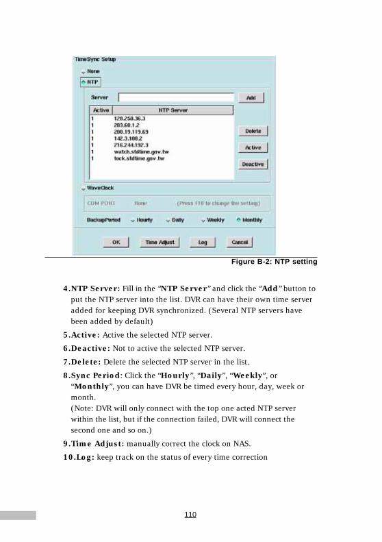
110
Figure B-2: NTP setting
4.NTP Server: Fill in the ‘’NTP Server’’ and click the ‘’Add’’ button toput the NTP server into the list. DVR can have their own time serveradded for keeping DVR synchronized. (Several NTP servers havebeen added by default)
5.Active: Active the selected NTP server.
6.Deactive: Not to active the selected NTP server.
7.Delete: Delete the selected NTP server in the list.
8.Sync Period: Click the “Hourly’’, “Daily”, “Weekly”, or“Monthly”, you can have DVR be timed every hour, day, week ormonth.(Note: DVR will only connect with the top one acted NTP serverwithin the list, but if the connection failed, DVR will connect thesecond one and so on.)
9.Time Adjust: manually correct the clock on NAS.
10.Log: keep track on the status of every time correction

111
Appendix C
Audio
AudioDVR supports for only 1-CH audio recording. Providing audio recording andaudio playback via built-in audio device of mothboard.
Steps:
1.Click the Setting icon on the main screen.
2.Select “ System Settings”
3.Click the Audio button to pop up the setting window.
Figure C-1: Click the sound button
Appendix C

112
Related settings as below:
Figure C-2:Sound Setling screen
Recording Property1.Camera select: only support 1CH audio for the first one camera.
2.Selecting Audio device: If select no recording, it will no sound whenplayback.
3.Quality: select “High” or “Low”. The better quality, the bigger file sizeis needed.
Playback Property
Click “Mute” for mute mode or adjust the “volume” slider for volume control.
Note: The volume is irrelative with the file’s capacity.
1.The real-time monitoring and playback screen with audio.Click the audio icon to switch to mute mode.

113
Appendix C
Figure C-3: Real-time monitoring screen with audio
Figure C-4: Playblack screen with audio
2.The real-time monitoring and playback screen in mute mode.Click the mote icon to switch to audio mode.

114
Figure C-5: Real-time monitoring screen in mute mode
Figure C-6: Playback screen in mute mode

115
Appendix D
Multi-Playback
Multi-Playback
Let’s take a look at how we can use the multi-playback function.
1.Click the ”playback” button on the main screen, and then
click (multi-playback), you’ll see the Multi-Playback windows asbelow.
Figure D-1: Multi-playback screen
2.Click to select the playback clips according to cameras anddate/time.
Figure D-2: Playback setting for the date, time and camera
Appendix D
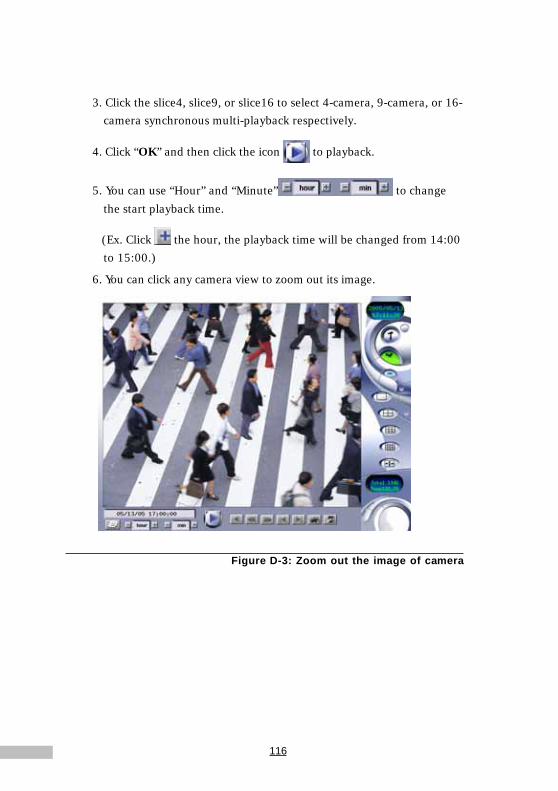
116
3. Click the slice4, slice9, or slice16 to select 4-camera, 9-camera, or 16-camera synchronous multi-playback respectively.
4. Click “OK” and then click the icon to playback.
5. You can use “Hour” and “Minute” to change
the start playback time.
(Ex. Click the hour, the playback time will be changed from 14:00
to 15:00.)
6. You can click any camera view to zoom out its image.
Figure D-3: Zoom out the image of camera

117
Appendix EAppendix E
TROUBLESHOOTINGYour Digital Video Recorder has passed through a series of rigorous qualityassurance tests to guarantee reliable performance. However, your new Digi-tal Video Recorder is a sophisticated piece of equipment; the system mal-function might occur if it is used incorrectly or if one of its components fails.Included here are important tips and information you will need to help locateand solve some of the problems you may encounter.
An Approach to TroubleshootingIn general, troubleshooting involves an organized systematic approach toproblem solving. Try to isolate the problem and identify the defective device(hardware) or improper setting (software). When you have a problem, youshould do a thorough visual inspection of the Digital Video Recorder. If noneof the indicators are lit and you cannot hear the HDD spinning, then theDigital Video Recorder is probably not receiving power. Make sure the powercord is plugged in, and securely connected. If you are using a power strip orsurge protector, ensure that these devices are turned on.
Improperly connected cables cause often problems. If you are using periph-erals such as a mouse or keyboard, make sure they are properly connectedto their respective ports. Ensure that none of the connectors’ pins are bent orbroken. Check all cables connected to the Digital Video Recorder. If any arecut, frayed, or damaged in any way, replace them right away.
Never use a damaged cable. A damaged cable is not only a fire hazard; itmay also cause a short circuit, resulting in irreparable damage to the DigitalVideo Recorder.
Isolating the ProblemThe problems that you will encounter can be divided into two basic categories:hardware problems and software problems. Hardware problems can be fur-ther divided into electrical and mechanical problems.
You will know you have a hardware problem if the screen is dark, the com-puter cannot read the disk drives, or you get an error message during thePower-On Self Test (POST).Software errors can occur at several levels. Inaddition, each application software package has its own set of error

118
messages. It is important to determine whether the software error mes-sage you are getting is from the operating system. Once you know this, youcan refer to your dealer for a solution to the problem.
Checking Cables and ConnectionsStart by performing a careful visual inspection of the exterior of the DigitalVideo Recorder. If no lights are displayed, make sure that your Digital VideoRecorder and its peripherals are getting power and communicating with eachother properly.
To check the power cables and connections:• Check the wall outlet or power strip with an item that you know is
functioning properly. A lamp or radio is a convenient item forchecking the power. You may also need to check the fuses andbreakers in your electric box.
• If the outlet is controlled by a wall switch, make sure that theswitch is on.
• If your Digital Video Recorder is plugged into a power strip with anOn/Off switch, make sure the switch is on.
With the Digital Video Recorder’s power switched off, check all cableconnections. If the Digital Video Recorder is connected to any peripheraldevices, look for loose or disconnected cables. If the Digital Video Recorderis too close to a wall, a cable connection may be loose or the cables may becrimped.
The Power-On Self TestThe Power-On Self Test (POST) runs every time you turn on or reset theDigital Video Recorder. The POST checks memory, the main system board,the display, the mouse, the disk drives, and other installed options.
A few seconds after you turn on your Digital Video Recorder, a copyright

119
Appendix Emessage appears on your display screen. A memory test message ap-pears next; as the test continues, memory size increases until all installedmemory is tested.
Two classifications of malfunctions can be detected during the POST:
• Error messages that indicate a failure with the hardware, thesoftware, or the Basic Input/Output System (BIOS). Thesecritical malfunctions prevent the Digital Video Recorder fromoperating at all or could cause incorrect and apparent results. Anexample of a critical error is CPU malfunction.
• Messages that furnish important information on the power-onand boot processes (such as memory status). These non-criticalmalfunctions are those that cause incorrect results that may not bereadily apparent. An example of a non-critical error would be amemory chip failure.
In general, if the POST detects a system board failure (a critical error), theDigital Video Recorder halts and sends out a series of beeps. If failure isdetected in an area other than the system board (such as the display, key-board or mouse) an error message is displayed on the screen and testing isstopped. It is important to remember that the POST does not test all areas ofthe Digital Video Recorder, but only those that allow it to be operational enoughto run diagnostic programs.
If your system does not successfully complete the POST, but displays ablank screen, emits a series of beeps, or displays an error code, consult yourdealer immediately.

120
- NOTES -

121
Appendix FAppendix F
CONFIGURING ACTIVEX
ActiveX is one type of VBscript. ActiveX is used for client-side communica-tion with the main application.
ActiveX SettingsThe relative settings of ActiveX can be configured in the manner describedbelow:When you get into the system, the window will pop-up a warning screenwhich is about the Active X setting; the details are as follows:
Figure F-1: Warning Window
The user could check “Always trust content from Softwell Technology
Co., Ltd.”, and then click “yes” to continue.
Figure F-2: Install DVR ActiveX

122
Choose which features of DVR Active X installer you want to install
1.DVR ActiveX: to copy the file to the computer
2.Start Menu Shortcuts
Figure F-3: Objects Selection
Figure F-4: Install Location Selection
Figure F-5: Installation Window
After finishing installation, then click “Close” .
123
Third Party Software Licenses
This system includes third party packages licensed under the GNU Gen-eral Public License (GPL), the GNU General Public License (GPL) Version2, GNU Lesser General Public License(LGPL) Version2.1, XFree86 License,Artistic License, and CGIC License. Please see the related Copyright No-tice for the terms of these licenses. Specifically, the following third partysoftwares are included in this product:
Copyright Notice
1. glibc-2.2.2-10.src.rpm(GPL)
2. bttv_0.9.11.6.zip(GPL)
3. imlib-1.9.8.1-2.src.rpm(GPL)
4. devfsd-2.4.2-2.src.rpm(GPL)
5. aumix-2.7-2.src.rpm(GPL)
6. gawk-3.0.6-1.src.rpm(GPL)
7. sh-utils-2.0-13.src.rpm(GPL)
8. bash-2.04-21.src.rpm(GPL)
9. textutils-2.0.11-7.src.rpm(GPL)
10.fileutils-4.0.36-4.src.rpm(GPL)
11.sed-3.02-9.src.rpm(GPL)
12.console-tools-19990829-34.src.rpm(GPL)
13.cpio-2.4.2-20.src.rpm(GPL)
14.gawk-3.0.6-1.src.rpm(GPL)
15.initscripts-5.83-1.src.rpm(GPL)
16.net-tools-1.57-6.src.rpm(GPL)
17.ed-0.2-19.src.rpm(GPL)
18.grep-2.4.2-5.src.rpm(GPL)
19.gettext-0.10.35-31.src.rpm(GPL)
20.tar-1.13.19-4.src.rpm(GPL)
21.gzip-1.3-12.src.rpm(GPL)
22.procps-2.0.7-8.src.rpm(GPL)
23.setserial-2.17-2.src.rpm(GPL)
24.mount-2.10r-5.src.rpm(GPL)
25.zsh-3.0.8-8.src.rpm(GPL)
26.gnome-libs-1.2.8-11.src.rpm(GPL)
27.esound-0.2.22-1.src.rpm(GPL)
28.efax-0.9-8.src.rpm(GPL)
29.apmd-3.0final-29.src.rpm(GPL)
30.sysklogd-1.4-7.src.rpm(GPL)
31.e2fsprogs-1.19-4.src.rpm(GPL)
32.libtermcap-2.0.8-26.src.rpm(GPL)
33.dosfstools-2.2-8.src.rpm(GPL)
34.modutils-2.4.2-5.src.rpm(GPL)
35.SysVinit-2.78-15.src.rpm(GPL)
36.pciutils-2.1.8-19.src.rpm(GPL)
37.rp-pppoe-2.6-5.src.rpm(GPL)
38.ghostscript-5.50-17.src.rpm(GPL)
39.findutils-4.1.6-2.src.rpm(GPL)
40.diffutils-2.7-21.src.rpm(GPL)
41.mgetty-voice-1.1.25-2.src.rpm(GPL)
42.db2-2.4.14-5.src.rpm(GPL)
43.gdbm-1.8.0-5.src.rpm(GPL)
44.readline-4.1-9.src.rpm(GPL)

124
45.slang-1.4.2-2.src.rpm(GPL)
46.libstdc++-2.96-81.src.rpm(GPL)
47.info-4.0-20.src.rpm(GPL)
48.mgetty-1.1.25-2.src.rpm(GPL)
49.mingetty-0.9.4-16.src.rpm(GPL)
50.linuxconf-1.24r2-10.src.rpm(GPL)
51.dip-3.3.7o-22.src.rpm(GPL)
52.ntsysv-1.2.22-1.src.rpm(GPL)
53.mutt-1.2.5i-9.src.rpm(GPL)
54.time-1.7-13.src.rpm(GPL)
55.dialog-0.9a-4.src.rpm(GPL)
56.eject-2.0.2-7.src.rpm(GPL)
57.gnome-core-1.2.4-16.src.rpm(LGPL/GPL)
58.LPRng-3.7.4-22.src.rpm(GPL andArtistic)
59.VFlib2-2.25.1-12.src.rpm(GPL2)
60.samba-client-2.0.7-36.src.rpm(GPL2)
61.logrotate-3.5.4-1.src.rpm(LGPL)
62.chkconfig-1.2.22-1.src.rpm(LGPL)
63.glibc-common-2.2.2-10.src.rpm(LGPL)
64.audiofile-0.1.11-1.src.rpm(LGPL)
65.gtk+-1.2.9-4.src.rpm(LGPL)
66.gdk-pixbuf-0.8.0-7.src.rpm(LGPL)
67.glib-1.2.9-1.src.rpm(LGPL)
68.XFree86-devel-4.0.3-5.src.rpm(XFree86)
69.cgic201.tar.gz(cgic)
Please refer to http://www.perl.com/pub/a/language/misc/Artistic.html,http://www.gnu.org/licenses/lgpl.html, http://www.xfree86.org/legal/licenses.html, http://www.gnu.org/licenses/gpl.html, and http://www.boutell.com/cgic/license.txt for the detail of related Copyright Notices.
