table of contents: section 8 - denver water · table of contents: section 8.0 ... autocad map 3d is...
TRANSCRIPT
Section 8.0 – Utilizing GIS Data via FDO Connections 8.0-1
CA
D S
ta
nd
ar
ds
-
3
rd
E
ditio
n –
N
ov
em
be
r 2
01
6
Section 8.0
Table of Contents: Section 8.0
Overview - Section 8.0 ......................................................................................................................................8.0-3
Choosing an Application ...................................................................................................................................8.0-3
Creating a Base Drawing Using Map 3D ..........................................................................................................8.0-3
Set Coordinate System ................................................................................................................................8.0-4
Add/Remove FDO Layers ............................................................................................................................8.0-6
Add Layers ..............................................................................................................................................8.0-6
Remove Layers .......................................................................................................................................8.0-7
Establish SDE Connection ................................................................................................................................8.0-9
Query Data ......................................................................................................................................................8.0-11
Single Layer ...............................................................................................................................................8.0-11
Multiple Layers ...........................................................................................................................................8.0-14
Save As AutoCAD Drawing.............................................................................................................................8.0-17
Quick Check ....................................................................................................................................................8.0-20
Convert FDO Drawing to DW Standards ........................................................................................................8.0-21
Layer Translator .........................................................................................................................................8.0-23
Automatic Layer Mapping .....................................................................................................................8.0-23
Manual Layer Mapping .........................................................................................................................8.0-24
Linetype Scales ..........................................................................................................................................8.0-26
Cleanup FDO Drawing ...............................................................................................................................8.0-26
GEOMAP Command .......................................................................................................................................8.0-26
Overview - Section 8.1 – E-Map Images via WMS Connections ......................................................................8.1-1
Adding An Aerial Image ....................................................................................................................................8.1-3
Resizing images ................................................................................................................................................8.1-4
Image GreyScale And Brightness Adjustment ..................................................................................................8.1-6
Display Order ....................................................................................................................................................8.1-7
Overview - Section 8.2 – SID Images via Raster Connections .........................................................................8.2-1
Adding An Aerial Image ....................................................................................................................................8.2-3
Resizing images ................................................................................................................................................8.2-9
Image GreyScale And Brightness Adjustment ................................................................................................8.2-11
8.0-2 Section 8.0 - Utilizing GIS Data via FDO Connections
CA
D S
ta
nd
ar
ds
-
3
rd
E
ditio
n –
N
ov
em
be
r 2
01
6
Display Order .................................................................................................................................................. 8.2-13
Combining Multiple Image Files ...................................................................................................................... 8.2-15
Reconnecting .................................................................................................................................................. 8.2-17
Disconnecting ................................................................................................................................................. 8.2-21
Section 8.0 – Utilizing GIS Data via FDO Connections 8.0-3
CA
D S
ta
nd
ar
ds
-
3
rd
E
ditio
n –
N
ov
em
be
r 2
01
6
Overview - Section 8.0
Within Denver Water AutoCAD Civil 3D is the primary application used to complete most work; however, AutoCAD Map 3D is the application used for pulling the GIS data into a drawing as actual AutoCAD objects, instead of “links”. In order for Denver Water’s GIS information to be accessed in AutoCAD the following FDO steps must be utilized.
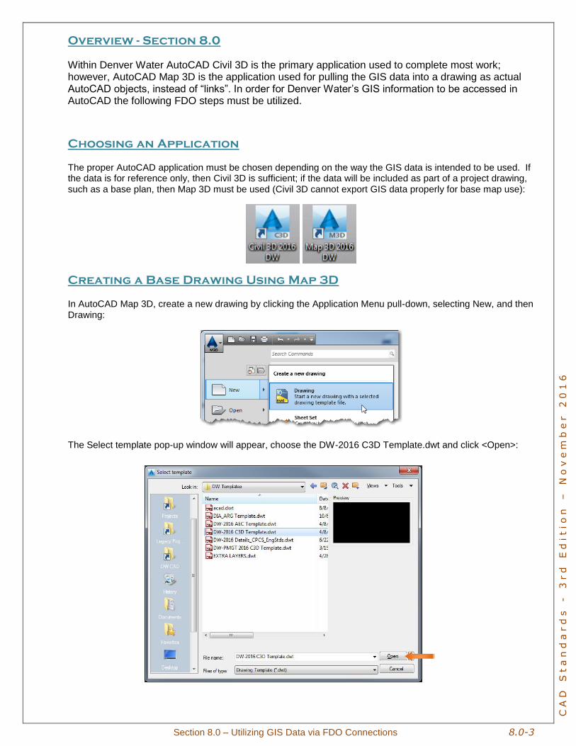
Choosing an Application
The proper AutoCAD application must be chosen depending on the way the GIS data is intended to be used. If the data is for reference only, then Civil 3D is sufficient; if the data will be included as part of a project drawing, such as a base plan, then Map 3D must be used (Civil 3D cannot export GIS data properly for base map use):
Creating a Base Drawing Using Map 3D
In AutoCAD Map 3D, create a new drawing by clicking the Application Menu pull-down, selecting New, and then Drawing:
The Select template pop-up window will appear, choose the DW-2016 C3D Template.dwt and click <Open>:
8.0-4 Section 8.0 - Utilizing GIS Data via FDO Connections
CA
D S
ta
nd
ar
ds
-
3
rd
E
ditio
n –
N
ov
em
be
r 2
01
6
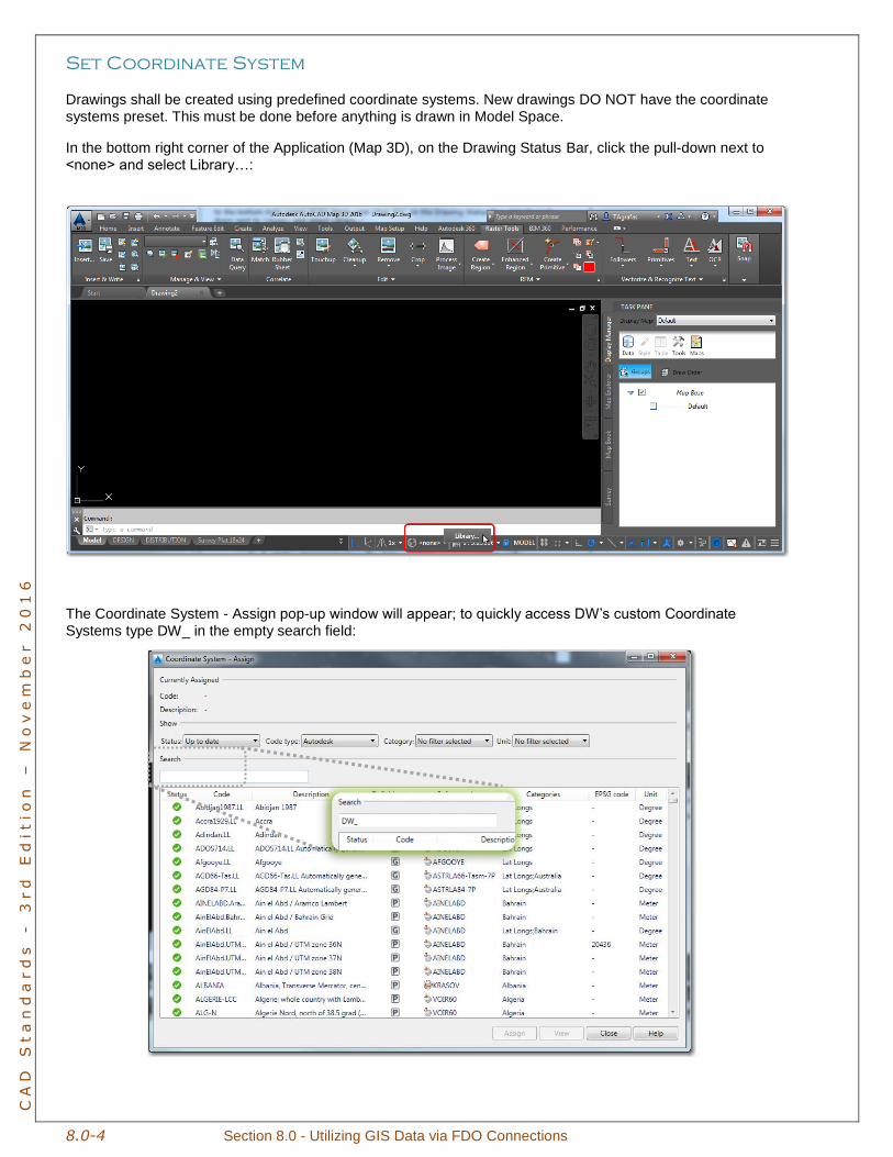
Set Coordinate System
Drawings shall be created using predefined coordinate systems. New drawings DO NOT have the coordinate systems preset. This must be done before anything is drawn in Model Space.
In the bottom right corner of the Application (Map 3D), on the Drawing Status Bar, click the pull-down next to <none> and select Library…:
The Coordinate System - Assign pop-up window will appear; to quickly access DW’s custom Coordinate Systems type DW_ in the empty search field:
Section 8.0 – Utilizing GIS Data via FDO Connections 8.0-5
CA
D S
ta
nd
ar
ds
-
3
rd
E
ditio
n –
N
ov
em
be
r 2
01
6
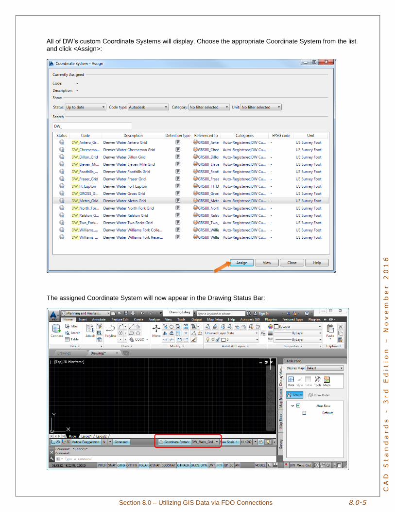
All of DW’s custom Coordinate Systems will display. Choose the appropriate Coordinate System from the list and click <Assign>:
The assigned Coordinate System will now appear in the Drawing Status Bar:
8.0-6 Section 8.0 - Utilizing GIS Data via FDO Connections
CA
D S
ta
nd
ar
ds
-
3
rd
E
ditio
n –
N
ov
em
be
r 2
01
6
Add/Remove FDO Layers
Custom, stylized layer files have been created to help quickly access GIS data. Use the following steps to add and remove layers.
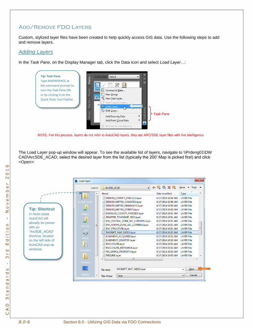
Adding Layers
In the Task Pane, on the Display Manager tab, click the Data icon and select Load Layer…:
NOTE: For this process, layers do not refer to AutoCAD layers, they are ARC/SDE layer files with live intelligence.
The Load Layer pop-up window will appear. To see the available list of layers, navigate to \\Prdeng01\DW CAD\ArcSDE_ACAD; select the desired layer from the list (typically the 200’ Map is picked first) and click <Open>:
Task Pane
Tip: Task Pane
Type MAPWSPACE at
the command prompt to
turn the Task Pane ON
or by clicking it on the
Quick Tools Tool Palette.
Tip: Shortcut In most cases
AutoCAD will
already be preset
with an
“ArcSDE_ACAD”
shortcut, located
on the left side of
AutoCAD pop-up
windows.
Section 8.0 – Utilizing GIS Data via FDO Connections 8.0-7
CA
D S
ta
nd
ar
ds
-
3
rd
E
ditio
n –
N
ov
em
be
r 2
01
6
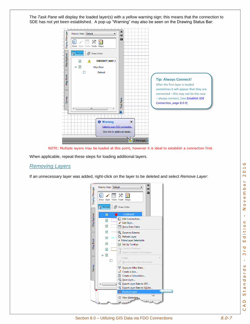
The Task Pane will display the loaded layer(s) with a yellow warning sign; this means that the connection to
SDE has not yet been established. A pop-up “Warning” may also be seen on the Drawing Status Bar:
NOTE: Multiple layers may be loaded at this point, however it is ideal to establish a connection first.
When applicable, repeat these steps for loading additional layers.
Removing Layers
If an unnecessary layer was added, right-click on the layer to be deleted and select Remove Layer:
Tip: Always Connect! After the first layer is loaded
sometimes it will appear that they are
connected – this may not be the case
– always connect, [see Establish SDE
Connection, page 8.0-9].
8.0-8 Section 8.0 - Utilizing GIS Data via FDO Connections
CA
D S
ta
nd
ar
ds
-
3
rd
E
ditio
n –
N
ov
em
be
r 2
01
6
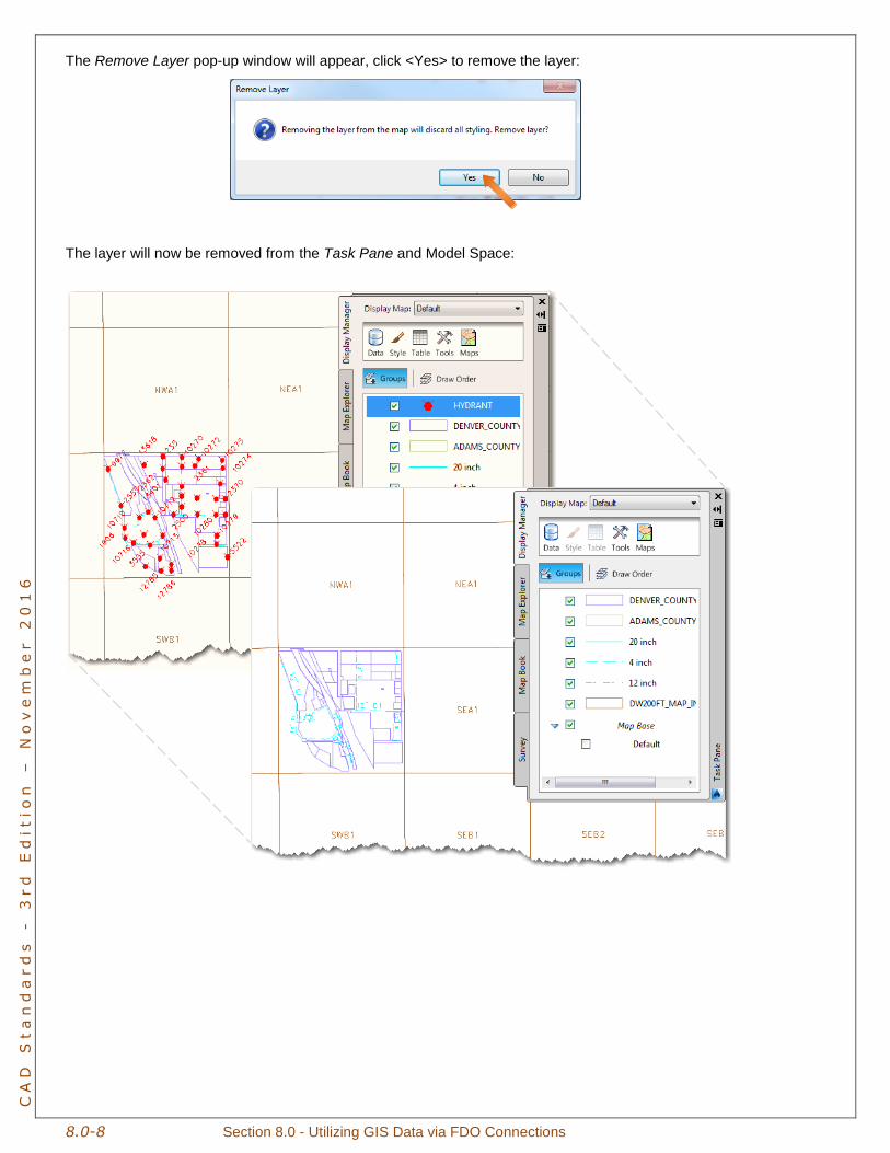
The Remove Layer pop-up window will appear, click <Yes> to remove the layer:
The layer will now be removed from the Task Pane and Model Space:
Section 8.0 – Utilizing GIS Data via FDO Connections 8.0-9
CA
D S
ta
nd
ar
ds
-
3
rd
E
ditio
n –
N
ov
em
be
r 2
01
6
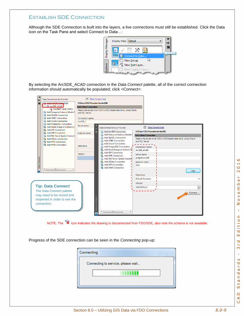
Establish SDE Connection
Although the SDE Connection is built into the layers, a live connections must still be established. Click the Data icon on the Task Pane and select Connect to Data…:
By selecting the ArcSDE_ACAD connection in the Data Connect palette, all of the correct connection
information should automatically be populated; click <Connect>:
NOTE: The icon indicates the drawing is disconnected from FDO/SDE, also note the schema is not available.
Progress of the SDE connection can be seen in the Connecting pop-up:
Tip: Data Connect The Data Connect palette
may need to be closed and
reopened in order to see the
connection.
8.0-10 Section 8.0 - Utilizing GIS Data via FDO Connections
CA
D S
ta
nd
ar
ds
-
3
rd
E
ditio
n –
N
ov
em
be
r 2
01
6
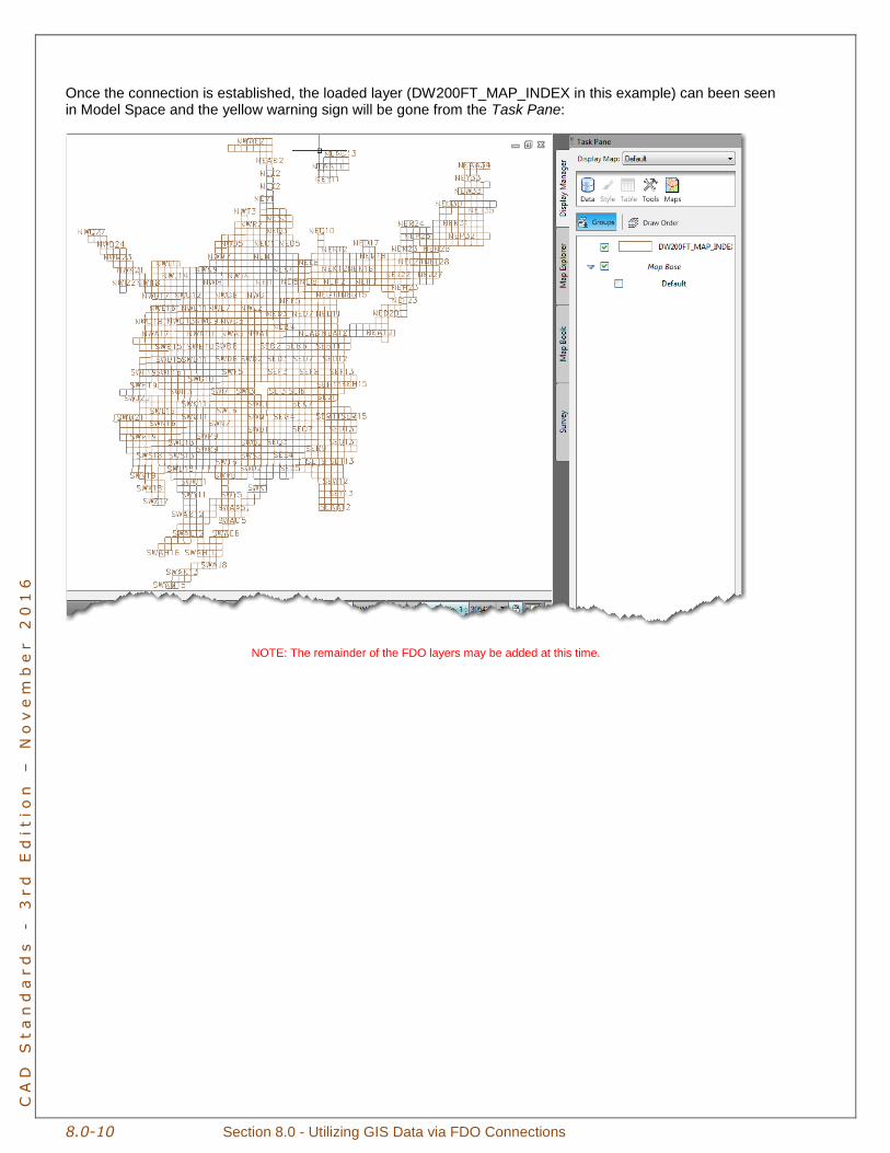
Once the connection is established, the loaded layer (DW200FT_MAP_INDEX in this example) can been seen in Model Space and the yellow warning sign will be gone from the Task Pane:
NOTE: The remainder of the FDO layers may be added at this time.
Section 8.0 – Utilizing GIS Data via FDO Connections 8.0-11
CA
D S
ta
nd
ar
ds
-
3
rd
E
ditio
n –
N
ov
em
be
r 2
01
6
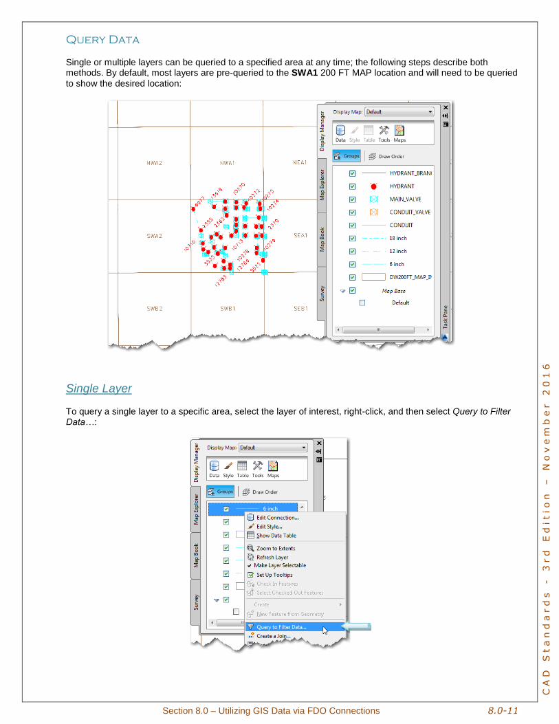
Query Data
Single or multiple layers can be queried to a specified area at any time; the following steps describe both methods. By default, most layers are pre-queried to the SWA1 200 FT MAP location and will need to be queried
to show the desired location:
Single Layer
To query a single layer to a specific area, select the layer of interest, right-click, and then select Query to Filter Data…:
8.0-12 Section 8.0 - Utilizing GIS Data via FDO Connections
CA
D S
ta
nd
ar
ds
-
3
rd
E
ditio
n –
N
ov
em
be
r 2
01
6
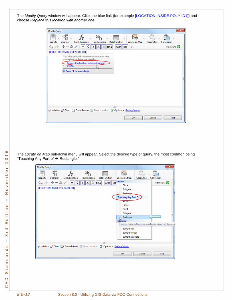
The Modify Query window will appear. Click the blue link (for example [LOCATION:INSIDE.POLY.ID1]) and choose Replace this location with another one:
The Locate on Map pull-down menu will appear. Select the desired type of query, the most common being
“Touching Any Part of Rectangle:”
Section 8.0 – Utilizing GIS Data via FDO Connections 8.0-13
CA
D S
ta
nd
ar
ds
-
3
rd
E
ditio
n –
N
ov
em
be
r 2
01
6
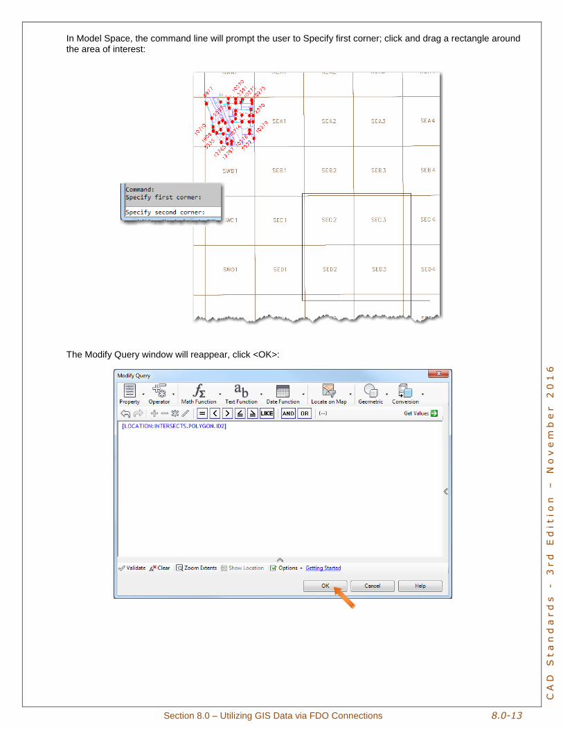
In Model Space, the command line will prompt the user to Specify first corner; click and drag a rectangle around the area of interest:
The Modify Query window will reappear, click <OK>:
8.0-14 Section 8.0 - Utilizing GIS Data via FDO Connections
CA
D S
ta
nd
ar
ds
-
3
rd
E
ditio
n –
N
ov
em
be
r 2
01
6
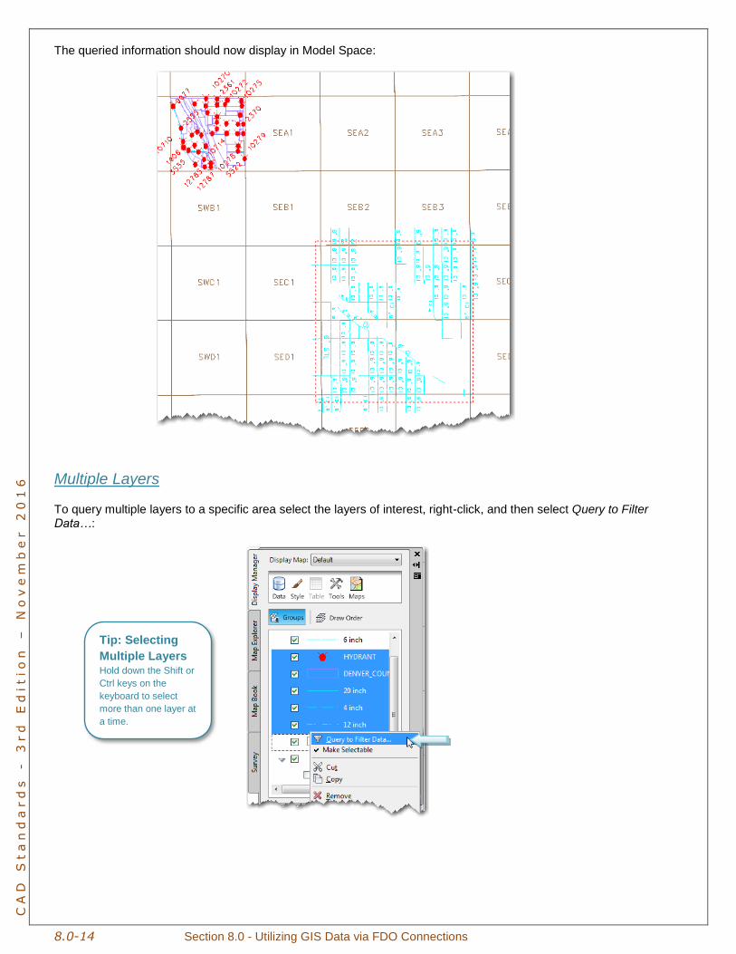
The queried information should now display in Model Space:
Multiple Layers
To query multiple layers to a specific area select the layers of interest, right-click, and then select Query to Filter
Data…:
Tip: Selecting
Multiple Layers Hold down the Shift or
Ctrl keys on the
keyboard to select
more than one layer at
a time.
Section 8.0 – Utilizing GIS Data via FDO Connections 8.0-15
CA
D S
ta
nd
ar
ds
-
3
rd
E
ditio
n –
N
ov
em
be
r 2
01
6
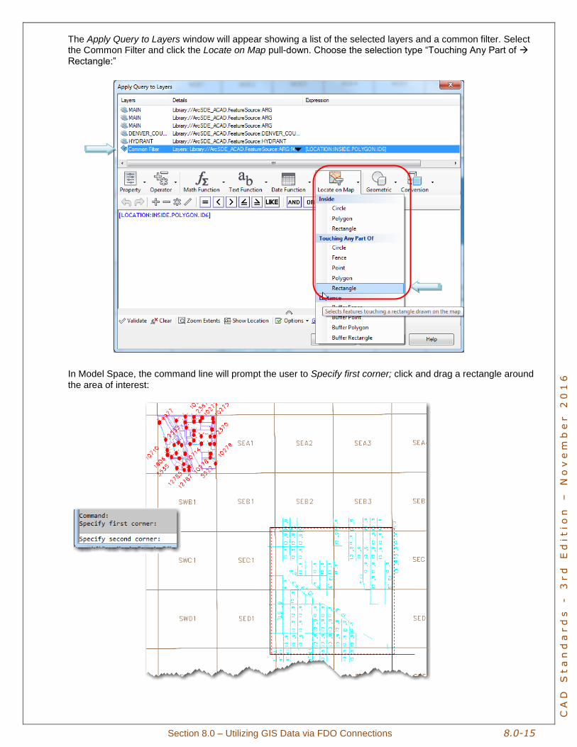
The Apply Query to Layers window will appear showing a list of the selected layers and a common filter. Select the Common Filter and click the Locate on Map pull-down. Choose the selection type “Touching Any Part of
Rectangle:”
In Model Space, the command line will prompt the user to Specify first corner; click and drag a rectangle around
the area of interest:
8.0-16 Section 8.0 - Utilizing GIS Data via FDO Connections
CA
D S
ta
nd
ar
ds
-
3
rd
E
ditio
n –
N
ov
em
be
r 2
01
6
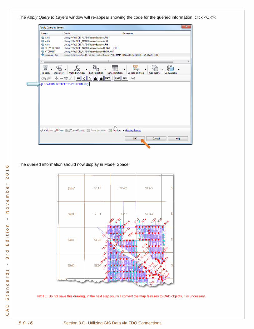
The Apply Query to Layers window will re-appear showing the code for the queried information, click <OK>:
The queried information should now display in Model Space:
NOTE: Do not save this drawing, in the next step you will convert the map features to CAD objects, it is uncessary.
Section 8.0 – Utilizing GIS Data via FDO Connections 8.0-17
CA
D S
ta
nd
ar
ds
-
3
rd
E
ditio
n –
N
ov
em
be
r 2
01
6
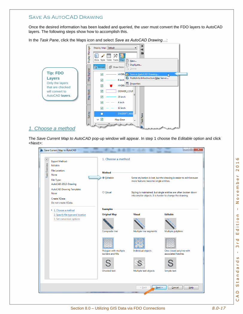
Save As AutoCAD Drawing
Once the desired information has been loaded and queried, the user must convert the FDO layers to AutoCAD layers. The following steps show how to accomplish this.
In the Task Pane, click the Maps icon and select Save as AutoCAD Drawing…:
1. Choose a method
The Save Current Map to AutoCAD pop-up window will appear. In step 1 choose the Editable option and click <Next>:
Tip: FDO
Layers Only the layers
that are checked
will convert to
AutoCAD layers.
8.0-18 Section 8.0 - Utilizing GIS Data via FDO Connections
CA
D S
ta
nd
ar
ds
-
3
rd
E
ditio
n –
N
ov
em
be
r 2
01
6
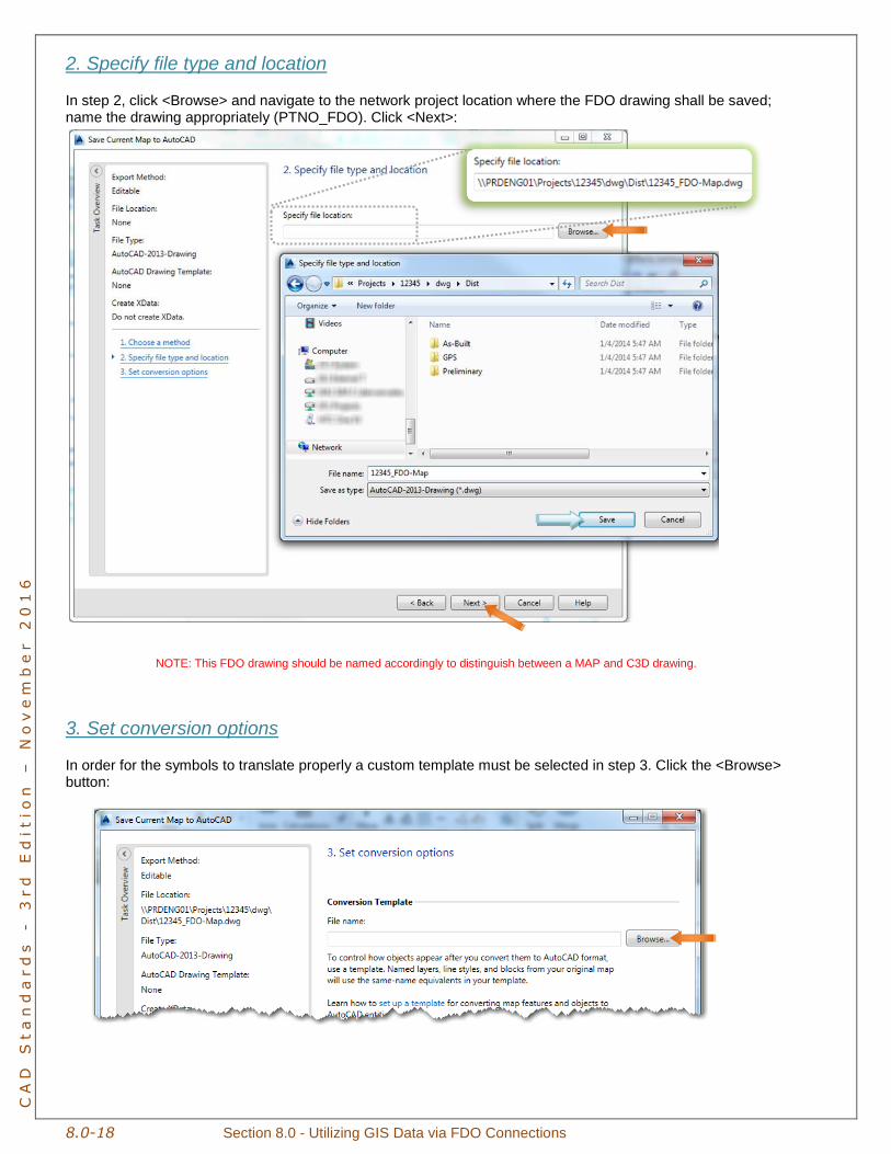
2. Specify file type and location
In step 2, click <Browse> and navigate to the network project location where the FDO drawing shall be saved; name the drawing appropriately (PTNO_FDO). Click <Next>:
NOTE: This FDO drawing should be named accordingly to distinguish between a MAP and C3D drawing.
3. Set conversion options
In order for the symbols to translate properly a custom template must be selected in step 3. Click the <Browse> button:
Section 8.0 – Utilizing GIS Data via FDO Connections 8.0-19
CA
D S
ta
nd
ar
ds
-
3
rd
E
ditio
n –
N
ov
em
be
r 2
01
6
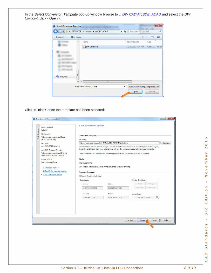
In the Select Conversion Template pop-up window browse to …DW CAD\ArcSDE_ACAD and select the DW Civil.dwt; click <Open>:
Click <Finish> once the template has been selected:
8.0-20 Section 8.0 - Utilizing GIS Data via FDO Connections
CA
D S
ta
nd
ar
ds
-
3
rd
E
ditio
n –
N
ov
em
be
r 2
01
6
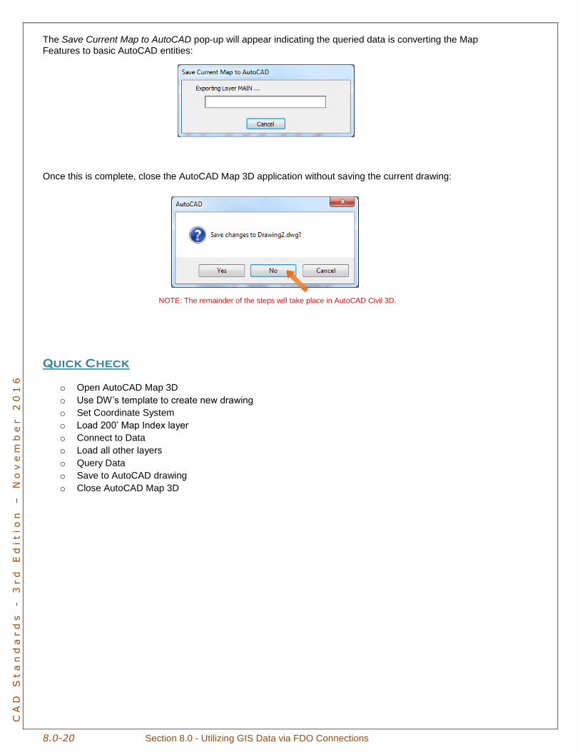
The Save Current Map to AutoCAD pop-up will appear indicating the queried data is converting the Map
Features to basic AutoCAD entities:
Once this is complete, close the AutoCAD Map 3D application without saving the current drawing:
NOTE: The remainder of the steps will take place in AutoCAD Civil 3D.
Quick Check
o Open AutoCAD Map 3D
o Use DW’s template to create new drawing
o Set Coordinate System
o Load 200’ Map Index layer
o Connect to Data
o Load all other layers
o Query Data
o Save to AutoCAD drawing
o Close AutoCAD Map 3D
Section 8.0 – Utilizing GIS Data via FDO Connections 8.0-21
CA
D S
ta
nd
ar
ds
-
3
rd
E
ditio
n –
N
ov
em
be
r 2
01
6
Convert FDO Drawing to DW Standards
The recently created FDO drawing will need to be converted to DW Standards before it is useable in a project drawing, the following steps accomplish this.
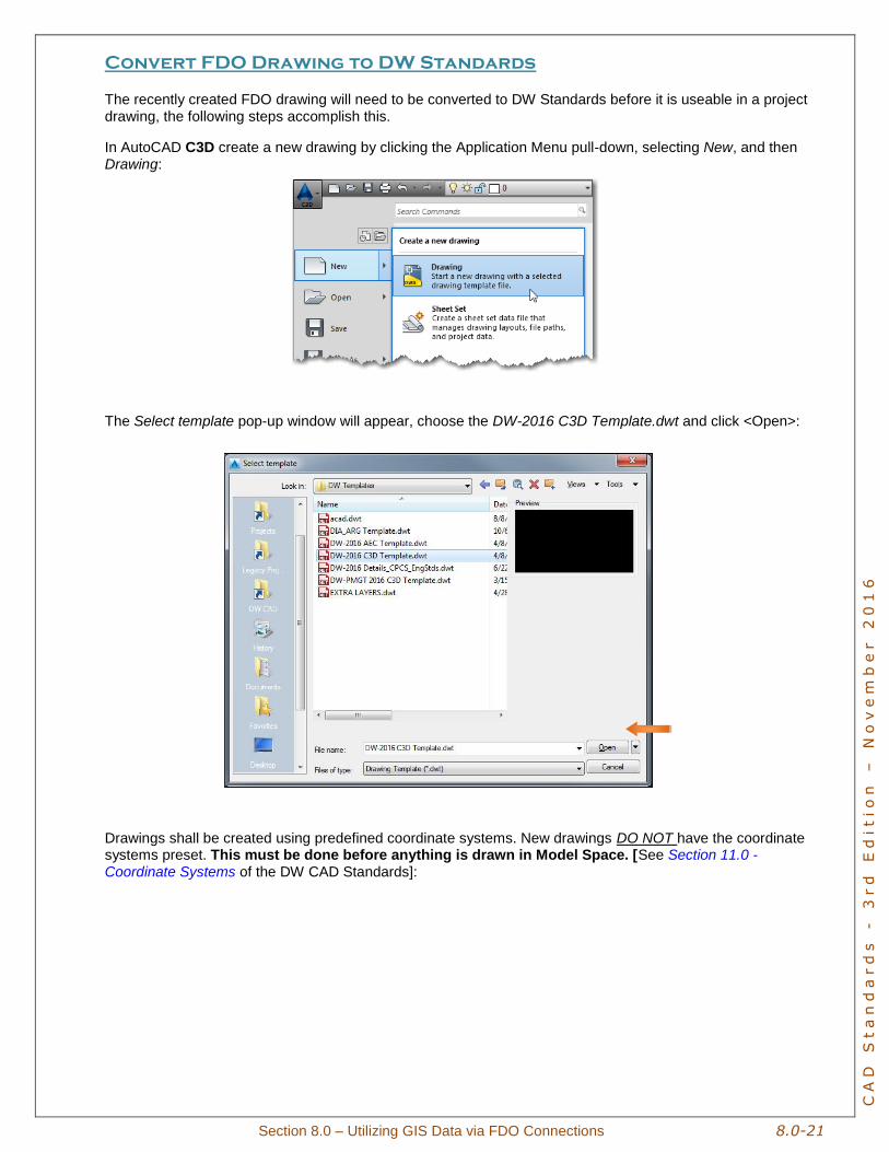
In AutoCAD C3D create a new drawing by clicking the Application Menu pull-down, selecting New, and then Drawing:
The Select template pop-up window will appear, choose the DW-2016 C3D Template.dwt and click <Open>:
Drawings shall be created using predefined coordinate systems. New drawings DO NOT have the coordinate systems preset. This must be done before anything is drawn in Model Space. [See Section 11.0 -
Coordinate Systems of the DW CAD Standards]:
8.0-22 Section 8.0 - Utilizing GIS Data via FDO Connections
CA
D S
ta
nd
ar
ds
-
3
rd
E
ditio
n –
N
ov
em
be
r 2
01
6
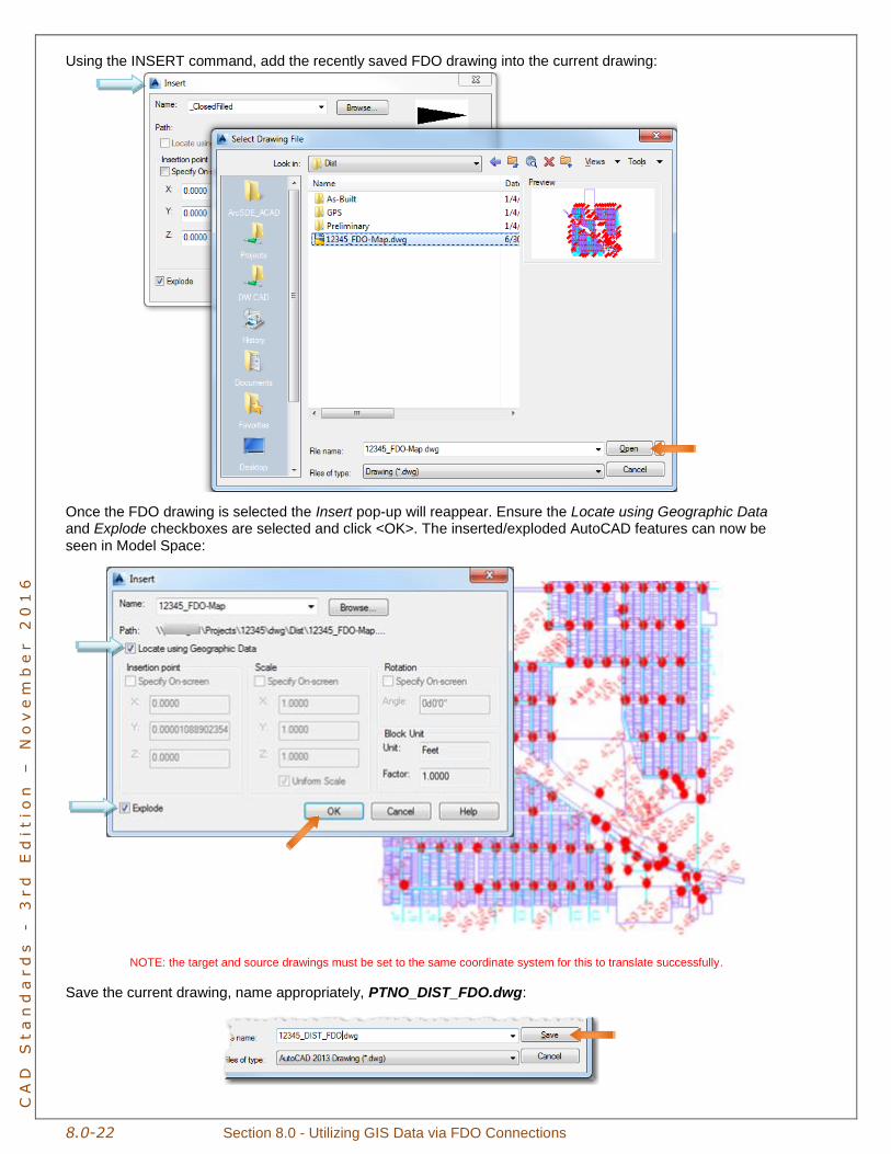
Using the INSERT command, add the recently saved FDO drawing into the current drawing:
Once the FDO drawing is selected the Insert pop-up will reappear. Ensure the Locate using Geographic Data and Explode checkboxes are selected and click <OK>. The inserted/exploded AutoCAD features can now be
seen in Model Space:
NOTE: the target and source drawings must be set to the same coordinate system for this to translate successfully.
Save the current drawing, name appropriately, PTNO_DIST_FDO.dwg:
Section 8.0 – Utilizing GIS Data via FDO Connections 8.0-23
CA
D S
ta
nd
ar
ds
-
3
rd
E
ditio
n –
N
ov
em
be
r 2
01
6
Layer Translator
Layers and symbols within the FDO drawing must be placed on the correct DW Standard layers [see Section 12.0: Layers & Linetypes of the DW CAD Standards for “GIS” layers]. The Layer Translator must be utilized in this process.
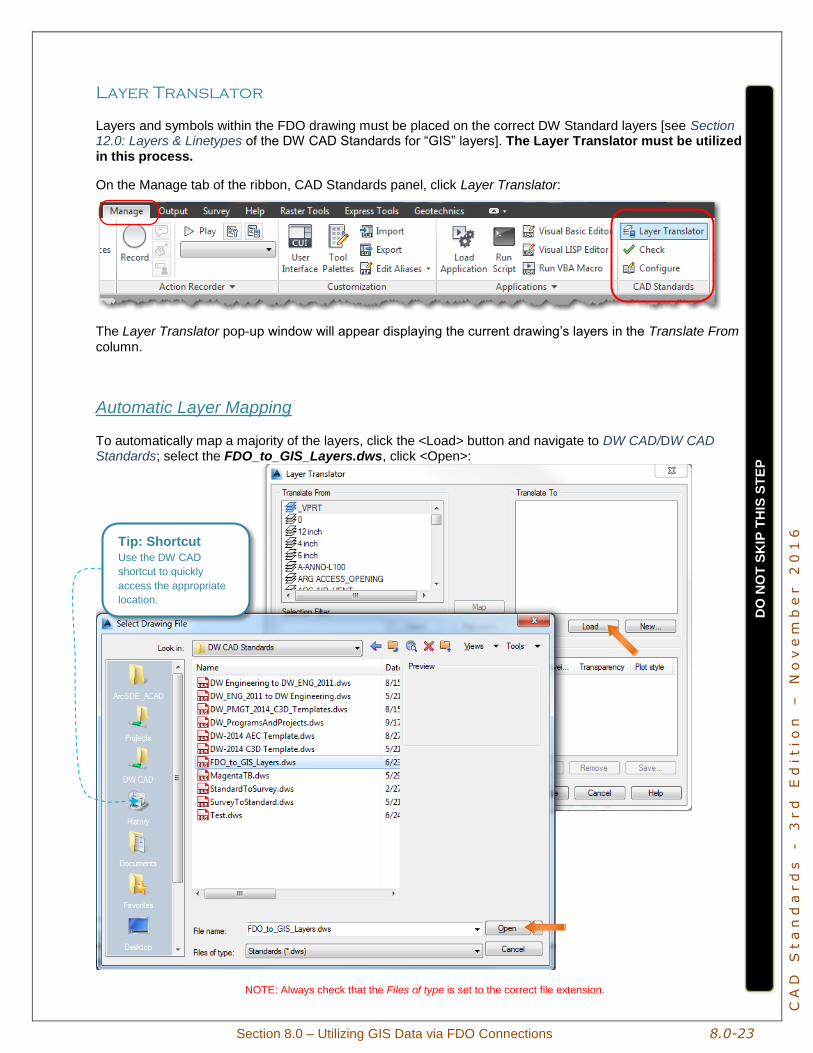
On the Manage tab of the ribbon, CAD Standards panel, click Layer Translator:
The Layer Translator pop-up window will appear displaying the current drawing’s layers in the Translate From
column.
Automatic Layer Mapping
To automatically map a majority of the layers, click the <Load> button and navigate to DW CAD/DW CAD Standards; select the FDO_to_GIS_Layers.dws, click <Open>:
NOTE: Always check that the Files of type is set to the correct file extension.
DO
NO
T S
KIP
TH
IS S
TE
P
Tip: Shortcut Use the DW CAD
shortcut to quickly
access the appropriate
location.
8.0-24 Section 8.0 - Utilizing GIS Data via FDO Connections
CA
D S
ta
nd
ar
ds
-
3
rd
E
ditio
n –
N
ov
em
be
r 2
01
6
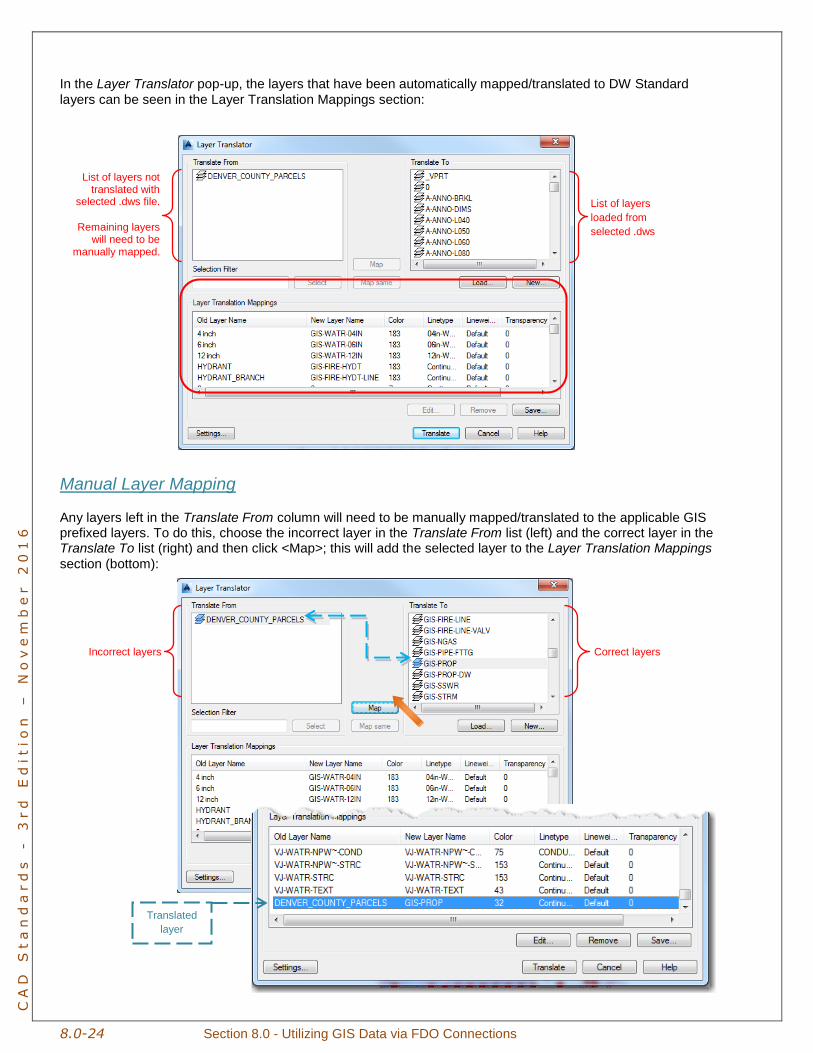
In the Layer Translator pop-up, the layers that have been automatically mapped/translated to DW Standard
layers can be seen in the Layer Translation Mappings section:
Manual Layer Mapping
Any layers left in the Translate From column will need to be manually mapped/translated to the applicable GIS prefixed layers. To do this, choose the incorrect layer in the Translate From list (left) and the correct layer in the Translate To list (right) and then click <Map>; this will add the selected layer to the Layer Translation Mappings
section (bottom):
Incorrect layers Correct layers
List of layers
loaded from
selected .dws
List of layers not translated with
selected .dws file.
Remaining layers will need to be
manually mapped.
Translated
layer
Section 8.0 – Utilizing GIS Data via FDO Connections 8.0-25
CA
D S
ta
nd
ar
ds
-
3
rd
E
ditio
n –
N
ov
em
be
r 2
01
6
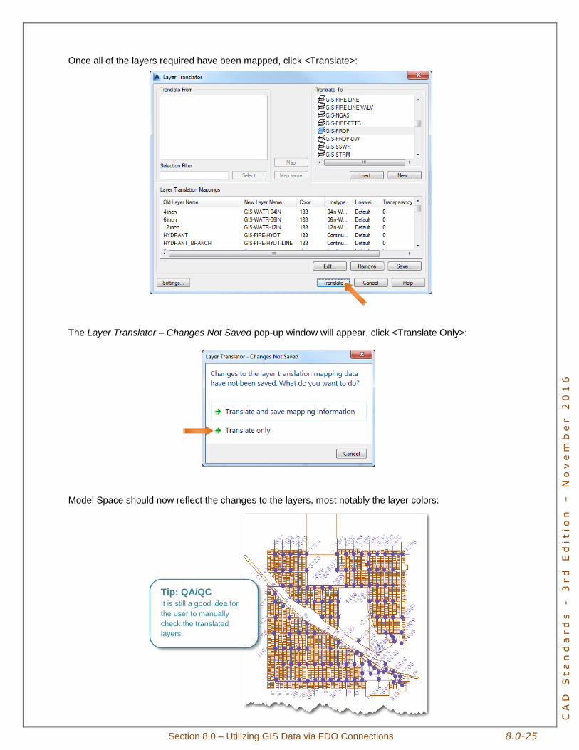
Once all of the layers required have been mapped, click <Translate>:
The Layer Translator – Changes Not Saved pop-up window will appear, click <Translate Only>:
Model Space should now reflect the changes to the layers, most notably the layer colors:
Tip: QA/QC It is still a good idea for
the user to manually
check the translated
layers.
8.0-26 Section 8.0 - Utilizing GIS Data via FDO Connections
CA
D S
ta
nd
ar
ds
-
3
rd
E
ditio
n –
N
ov
em
be
r 2
01
6
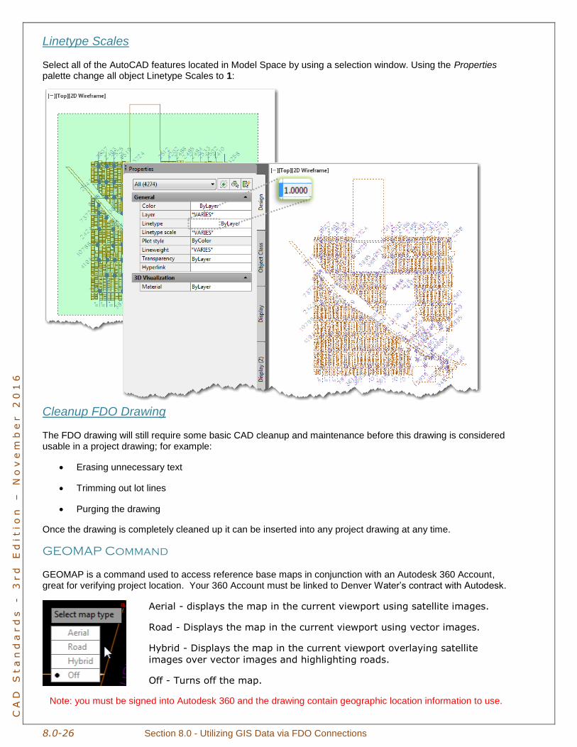
Linetype Scales
Select all of the AutoCAD features located in Model Space by using a selection window. Using the Properties palette change all object Linetype Scales to 1:
Cleanup FDO Drawing
The FDO drawing will still require some basic CAD cleanup and maintenance before this drawing is considered usable in a project drawing; for example:
Erasing unnecessary text
Trimming out lot lines
Purging the drawing
Once the drawing is completely cleaned up it can be inserted into any project drawing at any time.
GEOMAP Command
GEOMAP is a command used to access reference base maps in conjunction with an Autodesk 360 Account, great for verifying project location. Your 360 Account must be linked to Denver Water’s contract with Autodesk.
Aerial - displays the map in the current viewport using satellite images.
Road - Displays the map in the current viewport using vector images.
Hybrid - Displays the map in the current viewport overlaying satellite
images over vector images and highlighting roads.
Off - Turns off the map.
Note: you must be signed into Autodesk 360 and the drawing contain geographic location information to use.