table of contents - palm beach county,...
TRANSCRIPT

PALM BEACH COUNTY
THOROUGHFARE ROAD
DESIGN PROCEDURES
•
FEBRUARY 2006
•
A . ROVEDBY GEORGE T. WEBB, P.E.
COUNTY ENGINEER
•

TABLE OF CONTENTS
TITLE PAGE
A. Policies and Procedures.............................................. 2 - 4 B. Scope of Services........................................................ 5 C. Submittal Phases......................................................... 6 - 8 D. Phase Descriptions and Outlines
Phase I...................................................................... 9 - 15 Phase II..................................................................... 16 - 21 Phase III.................................................................... 22 - 23 Phase IV.................................................................... 24 Final Submittal.......................................................... 25
APPENDIX
A. Utility Coordination Guidelines................................... A-1 - A-4 B. Drainage Design Guidelines...................................... B-1 C. Right-of-Way Procurement Maps............................. C-1 - C-3 D. Legal Descriptions and Sketches.............................. D-1 E. Bridge Design Guidelines.......................................... E-1 - E-11 F. CADD System Design Guidelines…………………… F-1 - F-5
G. Signing, Pavement Markings & Signals Guidelines.. G-1
1
A. POLICIES AND PROCEDURES:
1. The Roadway Production Division shall be responsible for monitoring all thoroughfare roadway designs.
2. Design of thoroughfare roads shall comply with this document, and the current editions of
the Florida Department of Transportation Manual of Uniform Minimum Standards for Design, Construction and Maintenance for Streets and Highways, commonly known as the AFlorida Green Book@; the Florida Department of Transportation Plans Preparation Manual; and the Florida Department of Transportation Roadway and Traffic Design Standards, commonly known as the AFDOT Index@. The Consultant shall inform the Roadway Production Division of any conflicts between/among these documents. The Roadway Production Division shall recommend a resolution.
3. General consistency and clarity should be a top priority in the presentation of plans. To
promote consistent practices with micro-station files, the Consultant shall comply with the following:
a. New micro-station files will be created using a seed file provided by Palm Beach
County Engineering to ensure uniform working units configuration.
b. Custom menus addressing line styles, line weights, text sizes, etc. for roadway design, survey, and right-of-way work will be provided to ensure compliance with CADD System Design Guidelines. (See Appendix F)
c. Standard sheets (Title, Plan and Profile, Drainage and Cross Sections) are
available at the County Engineering Department.
d. One foot resolution digital orthos should be obtained from the County Engineering Department for use by the Consultant. Release of these copyrighted materials will require acknowledgment of the rules of use by the Consultant and all such materials will be returned with the submittal of final plans.
4. Plans shall be prepared on 11” x 17” sheets using Palm Beach County Standards. 5. The Consultant shall submit a minimum of four (4) sets of design plans to the Roadway
Production Division for each phase submittal, except for the final submittal.
6. All computations shall be done in accordance with Palm Beach County and State of Florida Department of Transportation Design Standards, taking into consideration the requirements of other permitting agencies, and shall be signed and sealed by the Professional Engineer preparing them.
2

A. POLICIES AND PROCEDURES: (continued)
7. All drainage systems shall be designed and constructed for ultimate roadway requirements,
unless otherwise directed by the Roadway Production Division. For existing drainage systems, proof shall be provided that the system in place was actually designed, permitted, and constructed for the ultimate roadway. Testing may be required to establish the condition and life expectancy of the existing system for the Engineering Department to determine if replacement is required. (See Appendix B)
8. The Consultant shall be responsible for coordination of utility locations, conflicts and
conflict resolution prior to the finalization of construction plans, and in accordance with the Utility Coordination Guidelines. (See Appendix A)
9. The Consultant shall be responsible for the preparation of all permit applications,
coordination with all permitting agencies, and preparation of permittable plans, as well as revisions required by the permitting agencies. A Roadway Production Division representative shall be present at all meetings with permitting agencies. Final construction plan approval shall be conditioned to the issuance of all required permits.
10. Soil borings shall be provided every 200' on alternating sides. Pavement cores shall be
obtained whenever existing pavement is to be reused and shall be provided every 1000', or as otherwise indicated by the Project Manager.
11. Each phase submittal shall include a progress report of the project schedule and list of
unresolved issues. Include a means of addressing these issues and reasons for delays.
12. The County shall monitor the plans for conformance with the Standards set forth herein and for consistency with the overall County Roadway Program. This monitoring of plans does not relieve the Consultant of his/her obligations and shall not be considered a quality control review.
3

A. POLICIES AND PROCEDURES: (continued)
13. At the completion of each review, the Consultant may be provided with a set of Amarked up plans@ (i.e. informal comments) from the Roadway Production Division and Traffic Divisions, and/or a comment letter.
14. The plans submitted for the next phase shall address all comments from the previous
submittal, both formal and informal. The Amarked up plans@ shall also be submitted along with written responses to all formal comments. Failure to follow this procedure could result in plans being returned to the Consultant without review.
15. The use of aerials is required for all Right-of-Way Procurement Maps, Drainage Maps, and
Plan Sheets. Sheet layout shall be set to avoid intersections at match lines. Sheets shall be set such that north is generally to the top or to the right of the page. These aerials shall include coverage of the existing roadway extending a minimum of 400' beyond the limits of construction and/or striping. Stationing shall increase from left to right of the sheet, and increase from south to north and from west to east. Station equations shall be provided for the intersection of centerlines.
16. Palm Beach County Thoroughfare Road Design Procedures will be updated periodically
and the latest revision shall be considered a part of this document. These revisions will be determined and issued by the Director of Engineering & Public Works Operations. The latest copy will be available in the Roadway Production Division reception area.
4
B. SCOPE OF SERVICES:
The County’s Project Manager and Project Engineer shall have a Scope Meeting with the Consultant. The County’s Traffic, Survey, and Right-of-Way Acquisition Divisions/Sections will also be included. If a bridge exists on the project, the Bridge Review Consultant for the project should also be present. This meeting shall be scheduled by the Project Manager. At this meeting, the design requirements will be set forth for the project. The following will be addressed and/or provided by Palm Beach County at the Scope Meeting:
a. Typical Section.
b. Access Management Issues.
c. Additional Turn Lane Requirements.
d. Drainage Issues.
e. Available Records (drainage, utilities, maintenance, existing development
conditions, anticipated future development conditions, contaminated areas identified by Environmental Resources Management (ERM), etc.).
f. Palm Beach County will begin the process to provide the Consultant with:
- An updated ownership list with copies of all right-of-way deeds along the project.
- Copies of plats in the vicinity.
g. Public Involvement Issues.
h. Design schedule.
i. The consultant is to provide aerial views of the entire roadway corridor as a basis for discussion.
5

C. SUBMITTAL PHASES (See Appendix “E”, Page 9 for Bridge Submittal Phases)
PHASE I
PHASE IA - Initial Utility Contact Plans PHASE IB - Typical Section PHASE IC - Master Plan
PHASE ID – 35% Submittal
1. Title Sheet. 2. Approved Typical Section. 3. Preliminary Drainage Map. 4. Preliminary Geometrics. 5. Benchmarks, Reference Points and Sectional Corners. 6. Right-of-Way Lines, Baseline of Survey and Centerline of Construction 7. Preliminary Drainage Design. 8. Preliminary Profile Grade Lines (Existing and Proposed). 9. Existing Drainage.
10. Back of Sidewalk Profiles. 11. Existing Ditch/Detention Area Plan and Profile. 12. Existing Intersection Profiles. 13. Existing Cross Sections. 14. Existing Ditch Cross Sections. 15. Preliminary Right-of-Way Procurement Map (if required) (1”=40’). 16. Bridge Construction Plans (See Appendix E). 17. List of Required Permits.
6

PHASE II
PHASE IIA - Utility Pothole Coordination Plans
PHASE IIB - First Utility Coordination Meeting
PHASE IIC - Pothole Underground Utilities at Possible Conflict Points
PHASE IID (65% SUBMITTAL)
1. Phase I comments Addressed. 2. Summary of Quantities (items only).
3. Drainage Design Computations. 4. Drainage Maps. 5. Proposed Drainage in Plan. 6. Final Geometrics. 7. Geometric Computation Book. 8. Plateaued Intersection Sheets. 9. Final Profiles.
10. Limits of Construction. 11. Proposed Ditch/Detention Area Plan and Profile. 12. Intersection Profile Sheets. 13. Proposed Cross Sections. 14. Proposed Ditch Cross Sections. 15. Existing Utilities. 16. Driveway Profile Sheets (existing and proposed). 17. Special Detail Sheets. 18. Bridge Construction Plans (See Appendix E). 19. Preliminary Signing and Pavement Marking Plans. 20. Preliminary Signal Plans (if required). 21. Proposed Right-of-Way Procurement Map (if required).
PHASE IIE - Stake Existing and Proposed Right-of-Way
PHASE IIF - Field Review of Proposed Right-of-Way, Easements, Restorations,etc.
PHASE IIG - Right-of-Way Documents
1. 100% Right-of-Way Procurement Map (if required). 2. Legal Descriptions and Sketches. (See Appendix C)
PHASE IIH - All Permits Applied For
7

PHASE III
PHASE IIIA - Utility Conflict Resolution Plans
PHASE IIIB - Second Utility Coordination Meeting (Final Conflict Resolution)
PHASE IIIC (96% SUBMITTAL)
1. Phase II Comments Addressed. 2. Special Provisions for Construction Specifications. 3. Summary of Quantities Sheet. 4. Utilities on Plan and Profile. 5. Drainage on Drainage Map and Plan and Profile Sheets. 6. Ditch/Detention Area Plan and Profile. 7. Traffic Control Plans (if required). 8. Signing and Pavement Marking Plans. 9. Signal Plans (if required).
10. Drainage Structure Sheets. 11. Special Detail Sheets. 12. Cross Sections. 13. Ditch Cross Sections. 14. Quantity Computation Book. 15. Engineers Cost Estimate. 16. Bridge Construction Plans (See Appendix E).
PHASE IV
PHASE IVA - Final Utility Coordination Meeting PHASE IVB (100% SUBMITTAL)
1. Phase III Comments Addressed 2. All Permits Received
FINAL SUBMITTAL (INCLUDING BRIDGE PLANS)
1. One Complete Set of Signed and Sealed Plans. 2. Thirty (30) Sets of Plans. 3. Final Cost Estimate. 4. Electronic Copy of Pay Items. 5. Final Set of Special Provisions. 6. Final Right-of-Way Procurement Map (Signed & Sealed). 7. One Signed and Sealed Geometric Computation Book. 8. One Signed and Sealed Bridge Computation Book (if applicable). 9. One Signed and Sealed Drainage Computation Book.
10. One Signed and Sealed Quantity Computation Book. 11. All Electronic Files. 12. All Permits.
8

D. PHASE DESCRIPTIONS AND OUTLINES: PHASE I
PHASE IA - INITIAL UTILITY CONTACT PLANS:
See Utility Coordination Guidelines (See Appendix A).
PHASE IB – TYPICAL SECTION: Palm Beach County Standard Typical Section shall be adjusted to reflect project conditions. PHASE IC – MASTER PLAN: Include horizontal control and address all access management issues.
PHASE ID (35% SUBMITTAL):
1. TITLE SHEET:
The County shall provide a Typical Title Sheet and the Consultant shall include on this sheet the road name, limits, identify what the project entails (eg. 6 lane divided section), County project number, Commissioners= names and districts, location map, project length, engineering certification, reference to FDOT Index, index of sheets, and general notes or reference thereto.
a. LOCATION MAP:
The location map shall include the general vicinity and a delineation of the project, north arrow, section, township and range, and project limits with stationing, showing any exceptions and bridges.
b. PROJECT LENGTH:
A table shall be included showing the project length in feet and miles. Include any exceptions and the lengths of any bridges within the project limits.
c. ENGINEERING CERTIFICATION:
The following certification is required on the title sheet of all final plans:
I hereby certify that the attached plans and design are in substantial compliance with the Design Standards and criteria in effect on this date for the Palm Beach County Engineering Department and the State of Florida Department of Transportation.
DATE_______________
(Signed and Sealed) PROFESSIONAL ENGINEER #
At the final submittal, each and every sheet shall be signed and sealed by the Engineer of Record.
9

d. FDOT INDEX AND SPECIFICATION:
The latest edition shall be used for the design and shall be so referenced.
e. GENERAL NOTES:
These may be included on another sheet if space does not allow on the Title Sheet. However, reference must be made on the title sheet to the sheet where they are located. The following General Notes, at a minimum, shall be included where relevant:
1. Prior to the commencement of any excavation, the Contractor shall comply
with Florida Statute 556.105 for the protection of underground gas pipelines.
2. Grades shown are finished grades, unless otherwise noted.
3. Benchmark datum must be referred to the National Geodetic Vertical Datum
1929.
4. Existing Section, Quarter Section Corner, Property Corners, Palm Beach County Survey Control Monuments and all other permanent monuments located within proposed construction are to be referenced prior to construction and reset after construction by a Professional Surveyor and Mapper.
5. Unless otherwise shown, all existing drainage structures, within the limits of
construction, are to be removed.
6. Utilities are to be adjusted by others unless otherwise noted.
7. The location of the existing utilities shown in the plans are approximate only; the exact locations shall be determined by the Contractor prior to the start of construction. In addition, the Contractor shall be responsible to verify if Aother@ utilities (not shown in the plans) exist within the area of construction. Should there be utility conflicts, the Contractor shall inform the Engineer and notify the respective utility owners to resolve utility conflicts and utility adjustments, as required.
8. All utility companies within the project limits shall be listed with contact
person and phone number, as follows:
CONTACT PERSON UTILITY PHONE NUMBER
9. Utility locations may also be determined by calling Sunshine One-Call and the respective utility company.
10. Stations and offsets refer to the centerline of construction, unless otherwise
noted.
10
e. GENERAL NOTES: (continued)
11. Intersecting roads and driveways are to be graded as directed by the Engineer, unless otherwise noted.
12. Maintenance of Traffic shall be in accordance with current Florida DOT
Standards and the Manual on Uniform Traffic Control Devices.
13. All pipes shall be in accordance with Florida DOT and Palm Beach County requirements.
14. All inlet drainage structures shall have a minimum 2' sump, except control
structures. Weep holes shall not be a part of these sumps.
2. TYPICAL SECTION:
The Typical Section furnished at the Scope Meeting, as modified for the project, shall be a part of this and all future plan submittals. The ultimate typical section shall also be included. The design speed and pavement section shall be shown. Also include alternate pavement sections to be utilized at the option of the Contractor. The alternate sidewalk detail and a detail for placement of guardrail should also be included on this sheet, if relevant.
3. PRELIMINARY DRAINAGE MAP:
a. Drainage maps at a scale of 1"=200’ (11" X 17" sheets) shall be supplied for every
project on aerial photographs.
b. The plan view of the preliminary drainage map shall show the existing drainage system including outfalls and pipes, and shall also include section lines and corners, identification of canals maintained and design high water elevations of canals, limits of project, stationing, road center lines, identification of all adjacent and intersecting roadways, intersecting street center lines, intersecting street profile elevations at 100' intervals to one point past the drainage divide and a north arrow on each sheet.
c. The preliminary drainage map in the profile view shall include the limits of the project, stationing, canals, and all existing drainage facilities. Also indicate the maintained water elevation.
11
4. PRELIMINARY GEOMETRICS (PLAN AND PROFILE SHEETS):
a. The plan and profile sheets shall be prepared on 11" X 17" sheets to a scale of 1" equals 40' horizontally, and 1" equals 4' vertically. b. The preliminary geometrics shall be shown on aerial photographs. This should
include the geometrics for survey baseline, centerline of construction and right-of-way lines including stations, offsets from centerline of construction, curve data, angle points, bearings and ties to section lines.
c. All plan and profile sheets shall include a north arrow at the upper right corner of
the sheet.
d. All existing utilities shall be shown in the plan view with dashed lines. Indicate ownership, material and size of each underground utility.
e. Match lines are required when plans match at an uneven station or when plan
sheets are not contiguous. Show match lines, corresponding stations and sheet numbers in each case. Layout should be such that match lines do not occur at intersections.
5. BENCHMARKS, REFERENCE POINTS AND SECTIONAL CORNERS (PLAN AND PROFILE SHEETS):
a. Permanent benchmark spacing shall not exceed 1,200 feet, and shall be located
outside the construction area. Reference to the nearest benchmark shall be shown on each plan and profile sheet.
b. Reference points reflecting ties to baseline of survey shall be included. These ties
shall be located outside of the construction area. A separate sheet including all project ties is strongly recommended.
c Sectional corners shall be shown on all relevant sheets. Dimensioning shall be
provided from the centerline and baseline to all section lines within the plan limits.
6. RIGHT-OF-WAY LINES, BASELINE OF SURVEY AND CENTERLINE OF CONSTRUCTION (PLAN AND PROFILE SHEETS):
a. The proposed right-of-way lines shall be shown for the proposed roadway, as well
as existing right-of-way lines and easements (dashed) for intersecting streets and canals. Dimensions to the right-of-way lines from the centerline of construction along with stations and offsets at all changes in direction of the right-of-way line shall be shown on all plan and profile sheets. Whenever right-of-way procurement maps are not provided, the Consultant shall show existing road right-of-way lines on all plan sheets.
12
6. RIGHT-OF-WAY LINES, BASELINE OF SURVEY AND CENTERLINE OF CONSTRUCTION (PLAN AND PROFILE SHEETS): (continued)
b. The centerline of construction shall be shown on the plan view and shall include
station equations at all intersecting streets.
c. The centerline of construction shall be stationed and all profiles, structures, edge of pavement, offsets, etc. shall be referenced from this line, unless otherwise directed by the Roadway Production Division.
d. Centerline curve data shall be provided on the drawings indicating angle point
station, delta angle with direction, degree of curvature, tangent length, length of curve, radius, super-elevation rate, P.C. station and P.T. station. Where the curve extends over more than one sheet, the curve data shall be repeated on each sheet. Curve data shall also be provided for curves not concentric with the centerline.
e. The baseline of survey with bearings, curve data, angle point stations, ties to
permanent monuments, reference to section lines, and relation to centerline of construction shall be indicated on the plans.
7. PRELIMINARY DRAINAGE DESIGN (PLAN AND PROFILE SHEETS):
Preliminary flood routing computations shall also be included with this submittal for the 25 year, 3 day storm, using the variable tailwater method. (See Appendix B for additional information).
8. PRELIMINARY PROFILE GRADE LINES (EXISTING AND PROPOSED)
(PLAN AND PROFILE SHEETS):
a. The profile shall be set as per the drainage requirement standards (requiring at least one through lane in each direction to be above the 25 year, 3 day storm stage for the roadway being built), or as set by the back of sidewalk profiles if so directed by the Roadway Production Division.
b. Profile grade lines shall be labeled and slopes shall be shown on all profiles to two
decimal places. c. Elevations are required at the beginning and end of each sheet, point of vertical
intersection (PVI), point of vertical curve (PVC), and point of vertical tangency (PVT), and at 100 foot stations. The k value and curve length shall also be indicated. In vertical curves and super-elevated sections, proposed elevations shall be shown at every 50 foot station, and high and low point stations and elevations shall be shown.
d. If super elevation is required, the edge of pavement profile shall be shown through
the super elevation transition, including beginning and end stations.
13
8. PRELIMINARY PROFILE GRADE LINES (EXISTING AND PROPOSED) (PLAN AND PROFILE SHEETS: (continued)
e. Special edge of pavement profiles are required wherever elevations in sag curves result in slopes flatter than 0.3%.
f. The existing (dashed lines) and proposed (solid lines) grades at the profile grade
lines (PGL) shall be shown in the profile view. The proposed lines shall be heavier.
g. All available utility information shall be shown in the profile view.
9. EXISTING DRAINAGE IN PLAN AND PROFILE:
All existing drainage shall be shown in the plan and profile views with a dashed line. Pipe sizes and materials shall be included in the plan view.
10. BACK OF SIDEWALK PROFILES:
Back of sidewalk profiles shall be a requirement in cases of new construction in urban areas. If required, these profiles shall be submitted prior to setting the preliminary profile grade lines. Back of sidewalk profiles shall be used to set the proposed grades unless the drainage condition controls, and shall also include existing elevations at the right-of-way line, proposed back of sidewalk grades, finished floor elevation of buildings within 25 feet of the proposed right-of-way, elevation and limits of intersecting streets, adjacent parking lots, driveways, walls, etc. The proposed profile shall be the result of an existing condition best fit and meeting the requirement of one through lane in each direction to be above the 25 year, 3 day storm stage.
A field review with County staff may be required, at the discretion of the Roadway Production Division.
11. DITCH/DETENTION AREA PLAN AND PROFILE (EXISTING):
Ditch/detention area plan and profile shall include existing plan and elevation, baseline of survey, centerline of construction, north arrow, and scale. Existing outfalls shall also be shown.
12. EXISTING INTERSECTION PROFILES:
Plans shall include existing profiles for all intersecting roads and major driveways. Existing centerline of pavement and swale profiles shall be included, up to 20' past the Amatch existing@ point or the drainage divide, whichever is furthest.
14

13. EXISTING CROSS SECTIONS:
Existing cross sections shall be provided at a minimum of each 100' station. In areas of super-elevation, sections shall be shown at 50' intervals. Cross sections shall show the right-of-way lines, centerline of construction, survey baseline (including offset from the centerline) vertical and horizontal scales, existing ground as a dashed line extending to 25' outside of the proposed right-of-way, and any walls, fences, trees or hedges within this 25' area. The station for which the cross section is prepared along with the elevation grid, shall be shown on the right side. Cross sections shall be plotted at a scale of 1" equals 5' vertically and 1" equals 10' horizontally, on grid paper. The existing elevation shall be shown at the centerline of construction just below the cross section.
14. DITCH CROSS SECTIONS (EXISTING):
These shall follow the same Standards as the Roadway Cross Sections and shall be shown on separate sheets tied to a baseline.
15. PRELIMINARY RIGHT-OF-WAY PROCUREMENT MAPS (See Appendix C):
a. Right-of-Way Procurement Maps shall be required for all projects, unless otherwise directed by the Roadway Production Division. There are supplemental requirements included in this publication, under the heading Right-of-way Procurement Map. (See Appendix C). Please refer to these also.
b. Right-of-Way Procurement Maps shall utilize aerial photography or raster images
as a base for delineating property lines related to the proposed right-of-way lines. Sufficient survey information shall be shown on the document to enable a prudent Professional Surveyor and Mapper to locate and stake each parcel in the field. Maps are to be prepared at a scale no smaller than 1" equals 40'.
c. Each map shall have the official seal of the Professional Surveyor and Mapper
certifying that the special survey meets the minimum technical standards prescribed by Chapter 61G17-6 F.A.C., and that the map is a true and correct representation of the land surveyed under his responsible direction and supervision.
d. All right-of-way procurement maps shall utilize the same stationing as the
construction plans to allow for easy cross reference.
16. BRIDGE CONSTRUCTION PLANS (35%):
See Bridge Design Guidelines. (See Appendix E)
17. LIST OF REQUIRED PERMITS:
Provide a complete list of all the permits required for the project.
15
PHASE II:
PHASE IIA - UTILITY POTHOLE COORDINATION PLANS:
See Utility Coordination Guidelines. (See Appendix A)
PHASE IIB- FIRST UTILITY COORDINATION MEETING:
See Utility Coordination Guidelines. (See Appendix A)
PHASE IIC - POTHOLE UNDERGROUND UTILITIES:
See Utility Coordination Guidelines. (See Appendix A)
PHASE IID (65% SUBMITTAL):
1. PHASE I COMMENTS INCORPORATED:
All comments from the previous review shall be addressed. Failure to do so may result in plans being returned without review.
2. SUMMARY OF QUANTITIES:
a. A Summary of Quantities sheet shall be included in the plans.
b. Only the items for the project shall be listed for this phase. No actual quantities are
required at this time.
c. Regular roadway pay items shall include all items definitely required for the construction of the project.
d. Contingency items shall also be indicated to cover any possible issues that may
arise during construction.
e. A Palm Beach County Standard Nomenclature file is available to the Consultant. Palm Beach County Pay Items sequence and nomenclature shall be used. Add Pay items as required.
16

3. DRAINAGE DESIGN COMPUTATIONS (REFER TO APPENDIX B):
4. DRAINAGE MAPS:
a. Drainage maps shall show the proposed drainage system in plan view, including
delineation of the contributing drainage basin, sub-basins, area of each sub-basin, outfalls, detention/retention areas (including control elevations and 25 year, 3 day storm elevations), structure numbers, pipes in solid lines, and their sizes and overland flow direction.
b. The profile views shall include as a minimum, the proposed profile (including PVI=s
and elevations), pipes and outfalls, and all drainage structures on the mainline.
c. All proposed drainage shall be drawn using solid lines, all existing drainage shall be shown using dashed lines.
5. PROPOSED DRAINAGE IN PLAN:
a. All drainage structures, drainage pipes and french drains (exfiltration trenches)
shall be shown and labeled in the plan view. This shall include structure types and numbers, trench dimensions, and pipes (size and material).
b. Drainage structures shall be located for the ultimate typical section.
c. Main line pipes shall be sized for the ultimate section.
6. FINAL GEOMETRICS (PLAN AND PROFILE SHEETS):
a. Final geometry of all intersecting streets shall be shown.
b. The limits of driveway restoration/reconstruction, type of pavement, limits of 6" concrete sidewalk and drop curbs shall be shown.
c. All curb return radii shall be indicated. PC and PT stations and elevations at the
edge of pavement shall be shown. High points and low points within the curb return shall be noted with stations, offsets, and elevations at the edge of pavement.
d. All sidewalks shall be located in accordance with the typical section. In curb
sections, sidewalk curb ramps shall be provided in accordance with the Florida DOT Standards.
17

7. GEOMETRIC COMPUTATION BOOK:
The Geometric Computation Book shall include all the necessary computations required to define (i) the centerline and PGL alignment, and (ii) super-elevation and super-elevation transitions (all transitions and elevations shall consider the ultimate section).
8. PLATEAUED INTERSECTION SHEETS:
a. All major intersections with other thoroughfare roadways shall be plateaued on
separate plan sheets.
b. All approaches shall be plateaued considering the ultimate expanded intersection.
c. Sheets shall include a north arrow, street names, centerlines, baselines, edges of pavement, traffic separators, curb and gutter, all lane lines and the necessary number of spot elevations to construct the plateaued intersection.
d. Special profiles shall be shown as required, including those for the existing
centerlines, proposed centerlines, lane lines, and edges of pavement.
e. Elevations and profiles shown on plateau intersection sheets shall not be duplicated on the plan and profile sheets.
f. Match lines will be used for cross-referencing.
9. FINAL PROFILES (PLAN AND PROFILE SHEETS):
Final profile grade line and any special profiles including station, offset, slopes, and elevation, shall be shown.
10. LIMITS OF CONSTRUCTION:
The limits of work, outside of the right-of-way, shall be indicated in the plan view. The line indicating this limit shall be labeled as the Alimit of construction@. This shall include:
(i) toe or top of slope or limits of trench required to construct underground
facilities, whichever is greater;
(ii) limit of driveway construction.
(iii) limits of work on side streets
Temporary construction easements shall not be labeled and restoration agreement lines shall not be shown on the construction plans.
11. DITCH/DETENTION AREA PLAN AND PROFILE (PROPOSED):
The ditch/detention area plan and profile shall include the proposed plan and elevations, and typical section.
18

12. INTERSECTION PROFILES SHEETS:
The plans shall include the proposed profiles and existing grades for all intersecting public rights-of-way, and major driveways. The centerline of pavement, gutterline and swale profiles shall be included.
13. PROPOSED CROSS SECTIONS:
Proposed cross sections shall show the proposed template, PGL elevations, soil borings, and the amount of cut, fill, and unsuitable material, where applicable. The cut and fill quantities shall be shown on the right side of the cross section sheet both in square feet for each cross section and cubic yards for the actual volumes between cross sections. Quantities for any unsuitable material shall be shown on the left side of the sheet in the same manner as for the cut and fill.
14. DITCH CROSS SECTIONS (PROPOSED):
These shall follow the same Standards as the Cross Sections.
15. EXISTING UTILITIES:
Existing utilities shall be shown in plan and profile views based on the pothole information from Phase IIC.
16. DRIVEWAY PROFILE SHEETS (EXISTING AND PROPOSED):
a. Partial sections shall be provided at all driveways. Driveway profiles shall extend
from proposed outside edge of pavement to 25' beyond the proposed right-of-way line, or to 10' beyond the limit of driveway construction, whichever is greater.
b. Driveway profiles shall carry the same information as required for intersection
profiles. 17. SPECIAL DETAIL SHEETS:
a. Detail sheets shall include all items proposed for construction which do not appear
in the Florida DOT indices and all modifications thereto.
b. Also required are details for the drainage control structures, including but not limited to, weir elevations, weir widths, orifice details, etc.
18. BRIDGE CONSTRUCTION PLANS (65%) (See Appendix E)
19. PRELIMINARY SIGNING AND PAVEMENT MARKING PLANS:
a. Signing and pavement marking plans are to be included as a separate set of plans,
with their own title sheet. They shall be in accordance with the Palm Beach County Traffic Division Standards.
b. This work shall be submitted to the Roadway Production Division with the 65%
roadway plans.
19

20. PRELIMINARY SIGNAL PLANS (IF REQUIRED):
a. The Traffic Division may require that signal plans be prepared by the Consultant. If
so, this will be made clear at the Scope Meeting.
b. Any signal installation or modification plans are to be included as a separate set of plans, with its own title sheet.
c. Signal plans shall be submitted to the Roadway Production Division with the 65%
roadway plans.
21. PROPOSED RIGHT-OF-WAY PROCUREMENT MAP:
a. The proposed right-of-way procurement map shall have addressed all previous
comments.
b. Parcels shall be identified as follows: 100 Series for Right-of-Way. 200 Series for all Permanent Easements (eg. Roadway, Embankment, Drainage, Utility, etc.). 300 Series for all Temporary Easements.
c. Provide a table listing all parcels required with corresponding stations and offsets.
PHASE IIE - STAKE EXISTING AND PROPOSED RIGHT-OF-WAY:
a. The right-of-way lines shall be staked by the Consultant=s Surveyor and Mapper in
preparation for field inspection.
b. Staking should not occur too far in advance of the field trip to reduce the possibility of the stakes being removed by others prior to the field review.
PHASE IIF - FIELD REVIEW OF PROPOSED RIGHT-OF-WAY, EASEMENTS,RESTORATIONS, ETC.:
a. A field review shall be conducted with the Roadway Production Division and the
Right-of-Way team if necessary to review the proposed right-of-way takes and analyze the need for the temporary construction easements.
b. Alternate construction methods shall be analyzed to eliminate the need for the
easements if feasible.
c. Necessary measures shall be taken to avoid existing signs, trees, hedges, etc. where feasible.
d. Special attention shall be paid to safe corners at intersections. Provisions should
be made to accommodate signal poles, especially mast arms.
20
PHASE IIG - RIGHT-OF-WAY DOCUMENTS:
1. 100% RIGHT-OF-WAY PROCUREMENT MAP (IF REQUIRED) (See Appendix C):
a. The final right-of-way procurement map should incorporate all previous comments.
b. Any required temporary construction, embankment, and drainage easements shall also be shown.
2. LEGAL DESCRIPTIONS AND SKETCHES (See Appendix D):
a. Legal descriptions and sketches will be required on parcels to be acquired, including but not limited to, right-of-way, temporary construction easements, embankment easements and drainage easements. Parcel sketches will agree with information on the right-of-way procurement map. All legal descriptions and sketches shall have the official seal and registration number of the Land Surveyor and Mapper who prepared the document.
b. The legals and sketches shall reference the centerline of construction for stationing
and offsets.
PHASE IIH - ALL PERMITS APPLIED FOR:
a. All permits shall be applied for upon receipt of 65% review comments.
b. Required permits that are the responsibility of the Consultant include, but are not limited to, SFWMD, all Water Control Districts, FDOT, ERM (vegetation and excavation permits), and Army Corps of Engineers.
c. The Consultant shall provide Palm Beach County with complete copies of the
packages submitted to the permitting agencies. This includes responses to comments from the review process.
21
PHASE III:
PHASE IIIA - UTILITY CONFLICT RESOLUTION PLANS:
See Utility Coordination Guidelines. (See Appendix A)
PHASE IIIB - UTILITY COORDINATION MEETING:
See Utility Coordination Guidelines. (See Appendix A)
PHASE IIIC (96% SUBMITTAL): PHASE IIE THROUGH PHASE IIH SHALL BE COMPLETED PRIOR TO THIS SUBMITTAL
1. PHASE IID COMMENTS INCORPORATED:
All comments from the previous review shall be addressed. Failure to do so may result in plans being returned without review.
2. SPECIAL PROVISIONS FOR CONSTRUCTION SPECIFICATIONS:
The Consultant shall be required to provide the County with any special provisions required for the particular project, whenever clarification or special conditions need to be addressed.
3. SUMMARY OF QUANTITIES SHEET:
a. Quantities shall be provided for all the items required for the project.
b. Pay item footnotes shall be included.
c. This sheet shall include a Summary of Earthwork.
4. UTILITIES ON PLAN AND PROFILE:
a. All pothole information shall be incorporated. b. Any conflict resolution measures shall be addressed.
5. DRAINAGE ON DRAINAGE MAPS, AND PLAN AND PROFILE SHEETS:
Pipe flow line elevations shall be shown. Yard drains shall be included where necessary.
6. DITCH/DETENTION AREA PLAN AND PROFILE:
Address all agency requirements and permit conditions, including littoral shelves.
7. TRAFFIC CONTROL PLANS (IF REQUIRED):
a. Traffic control plans (maintenance of traffic plans) shall be provided if required by
the Roadway Production Division or as a permit condition from a review agency.
b. Florida DOT Standards shall be followed for items to be included in this plan.
8. SIGNING AND PAVEMENT MARKING PLANS:
The plans shall include a tabulation of all the quantities required.
22
9. SIGNAL PLANS (IF REQUIRED):
a. Any specifications shall be provided at this stage.
b. The plans shall include a tabulation of all the quantities required.
10. DRAINAGE STRUCTURE SHEETS:
a. All drainage pipes and french drains (exfiltration trenches) shall be shown including the length of pipe, type of material, and flow lines.
b. All inlet drainage structures shall have a 2' sump.
c. All structures shall be shown, including location (center line of structure and offset),
elevation (pipe flow lines, bottom, and edge of pavement), and type of structure. Reference shall be made to the applicable Florida DOT indices.
d. All existing utilities shall be shown including ownership, size, depth, and conflict
resolution (if required).
11. SPECIAL DETAIL SHEETS: A final check shall be made to confirm all special details and coordination with applicable
plan sheets.
12. CROSS SECTIONS:
A final check shall be made of all the volumes for cut, fill and unsuitable material.
13. DITCH CROSS SECTIONS:
A final check shall be made of all the volumes for cut, fill and unsuitable material. 14. QUANTITY COMPUTATION BOOK:
a. A detailed computation book shall be submitted.
b. It shall detail all quantity computations and locations on a sheet by sheet basis.
c. It shall be in sufficient detail to justify the quantities as shown on the Summary of
Quantities sheet.
d. Quantities for the signing and pavement marking plans and signal plans should also be included.
e. Quantities for any bridges shall also be included.
15. ENGINEERS COST ESTIMATE:
a. A cost estimate shall be provided using present average unit costs. Recent bid
tabulations are available in the Roadway Production Division.
b. It shall include all items listed in the Summary of Quantities for the roadway plans, signing and pavement marking plans, signal plans and bridge plans.
16. BRIDGE CONSTRUCTION PLANS (96%):
See Bridge Design Guidelines (See Appendix E).
23

PHASE IV: PHASE IVA- FINAL UTILITY COORDINATION MEETING: See Utility Coordination Guidelines. (See Appendix A) PHASE IVB (100% SUBMITTAL): 1. PHASE III COMMENTS INCORPORATED: All comments from the previous review shall be addressed. Failure to do so may result in plans being returned without review. 2. ALL PERMITS RECEIVED: All permits should be in hand prior to this submittal.
24

FINAL SUBMITTAL: The Final Submittal shall consist of all the following documents: 1. One complete set of 11” x 17” signed and sealed plans with each sheet signed and sealed by a Registered Engineer for the roadway construction plans, the signing and pavement marking plans and the bridge plans. The right-of-way procurement maps shall be signed and sealed by a Registered Surveyor & Mapper. 2. Thirty (30) complete sets of plans (11” x 17”). 3. A signed and sealed final cost estimate. This also shall be provided in electronic format on disk. 4. A summary of all pay items, units and quantities in accordance with the Palm Beach County Standard Nomenclature shall be submitted in electronic format (Excel readable) for use in preparing construction contract documents. 5. A set of Special Provisions if required for the project, on disk in Word format.
6. One (1) Signed and Sealed Right-of-Way Procurement Map. 7. A Signed and Sealed Geometric Computation Book.
8. A Signed and Sealed Bridge Computation Book.
9. A Signed and Sealed Drainage Computation Book.
10. A Signed and Sealed Quantity Computation Book.
11. An electronic copy on disk with the complete design (in Micro station format following Palm Beach County CADD System Design Guidelines) for the roadway design, signing and
striping plans, bridge plans, and right-of-way procurement maps. In addition plat files of all drawing sheets shall be delivered in both micro-station and PDF formats.
12. All permits required for the project.
25
APPENDIX A
UTILITY COORDINATION GUIDELINES
INITIAL UTILITY CONTACT
1. Initial Utility Contact Plans are prepared by Consultant. These plans, including the approved typical section, shall be submitted to Palm Beach County (PBC) as soon as aerials are received and after centerline, proposed right-of-way lines, and intersecting street names are shown (PHASE IA). The Palm Beach County Utility Coordinator will determine which utilities should be contacted and requests reproducibles or two (2) sets of plans per Utility Company from the Consultant. The PBC Traffic Division shall always be included. 2. In an Initial Contact Letter (ICL), the Utility Coordinator requests available As-builts and sends the Initial Utility Contact Plans to the utility owners, requiring one (1) set to be marked and returned within a maximum of thirty (30) calendar days, or a letter stating that the utility has no facilities within the limits of the project. The ICL shall include a statement that when pot holing is required, the utility will be responsible for uncovering their facilities for location by PBC (or its Consultant) and/or any non destructive utility location services required. The ICL shall also request notification (and support documents) of any utility claims for reimbursement. 3. The Utility Coordinator forwards the marked plans and As-Builts to the Consultant within one week of receiving them from the Utility Companies.
A-1

ROADWAY DESIGN IS BETWEEN 35% AND 65% SUBMITTAL 1. The Consultant shows existing utilities and proposed drainage in plan (no backwater drainage
computations are necessary at this time). An Initial Utility Conflict Matrix (list of possible conflict points), a request for a pot holing meeting, and a set of utility pot hole coordination plans for each utility company (or reproducibles) is submitted by the Consultant. (PHASE IIA)
2. The Utility Coordinator provides all utility companies with the above referenced plans ten (10) working
days before the utility coordination meeting. 3. The First Utility Coordination Meeting is conducted and a pot holing and survey date is set (PHASE
IIB). Letter is sent to utilities confirming pot holing schedule. Letter to include statement that when potholing is required the utility will be responsible for uncovering their facilities for location by PBC (or its Consultant) and/or any non destructive utility location services required. PBC (or its Consultant) shall be responsible for marking either the Centerline of Construction or Baseline of Survey (as applicable) by painting station callouts at 100' intervals.
4. The Utility Company shall be responsible to pot hole underground utilities at possible conflict points
(PHASE IIC) within twenty (20) working days of Utility Coordination Meeting. The exposed utilities shall be surveyed by PBC (or its Consultant) within ten (10) working days after notification from utilities that pot hole locations are ready. Unless otherwise agreed upon, the utility company shall locate/mark their utilities either by;
- A 3" " diameter pvc pipe on top of the utility.
- Providing the offset and the cover depth of the utility from a physical feature (pavement,
curb, etc.) and marking (painting) that physical feature. 5. No vertical drainage design is to be done until all the pot holing information has been received and
transferred to the plans. 65% SUBMITTAL All pot holing information received to date shall be included in this submittal.
A-2

ROADWAY DESIGN IS BETWEEN 65% AND 96% SUBMITTAL 1. The Consultant completes drainage backwater computations, includes the pot holing information in the
plans, determines the physical placement (horizontal and vertical) of the proposed drainage pipes, and shows preliminary drainage in plan and profile sheets. The Consultants design must include the Abest effort@ to avoid all utility conflicts, when economically feasible.
2. The Consultant determines all unavoidable points of conflict and updates the Utility Conflict Matrix. 3. The Consultant provides PBC with current plans and updated Matrix (PHASE IIIA). 4. The Utility Coordinator provides all utility companies with the above referenced plans and the updated
Matrix ten (10) working days before the second utility coordination meeting. 5. The Consultant, PBC Roadway Production Division staff, and the affected Utilities conduct the second
Utility Coordination Meeting (Final Conflict Resolution) to address the updated Matrix and all unavoidable points of conflict. (PHASE IIIB)
6. The Consultant prepares Ameeting minutes@ (identifying resolved items) and a final Utility Conflict
Matrix. These are submitted to PBC who shall forward copies to each utility allowing ten (10) working days for any additional comments or objections.
7. Any costs associated with changes resulting from responses received after ten (10) working days will
be the sole responsibility of the Utility Company. 8. PBC in conjunction with its Consultant and the utility companies shall determine the necessity of:
a. An early clearing of selected areas to be included within the roadway construction contract, or
b. A separate clearing contract of selected areas. 9. Evaluation and discussion of forthcoming Utility Relocation Schedules
(for underground and overhead facilities).
Consultant=s AMeeting Minutes@ shall include a section with projected start and duration time periods. 96% SUBMITTAL: This submittal shall include all features of final drainage design, drainage structure sheets and existing utilities.
A-3
ROADWAY DESIGN IS BETWEEN 96% AND 100% SUBMITTAL 1. The Utility Coordinator sends out a ARelocation Schedule@ document to all Utility Companies. This
document shall request information pertaining to time/schedule for relocating and/or adding facilities. This document shall also request whether the Utility Company desires to include the work as part of the PBC bid package. Any requested reimbursement costs shall also be identified at this time. Any utilities in the area that are unaffected shall provide a letter to that effect. The Utility Company shall return completed ARelocation Schedule@ within twenty (20) working days after written request
2. Upon approval of 96% complete plans by PBC Roadway Production Division, the Consultant advises
the Utility Coordinator that all requested changes have been incorporated in the plans and that the final utility coordination meeting should be conducted.
3. A complete set of roadway plans is sent to the Utility Companies with a request to review for
compliance with previous agreements, to identify all contingency items, and to attend a final Utility Coordination Meeting. Any changes that take place beyond this point must be reflected in the revision box and the Utility Companies need to be notified of those changes prior to the “Pre-Advertisement meeting”.
4. The Final Utility Coordination Meeting (PHASE IVA) is conducted prior to the 100% Submittal. Any and
all utility related contingency items should be finalized at this time. The Palm Beach County Project Engineer and Utility Coordinators shall be present. The Consultant will record notes to be used in preparing the project construction specifications, and finalizing the plans for construction (including contingent utility related quantities).
5. The utility coordination is completed and the Consultant proceeds to prepare the 100% submittal. 6. Pre-advertisement meeting to include the status of utility relocation and completion.
A-4
APPENDIX B
DRAINAGE DESIGN GUIDELINES
All Thoroughfare Road Drainage Design shall comply with the Florida Department of Transportation Drainage Manual (latest Edition) and the following guidelines:
The values and methodology presented in these guidelines and supplemental references are Palm Beach County Standards. Deviations from these guidelines shall be documented within the required Drainage Design Computation Book at each instance of deviation, and must receive written authorization from Palm Beach County. A Drainage Design Computation Book shall be prepared and one (1) signed and sealed by the Professional Engineer in responsible charge, shall be submitted to Palm Beach County. The Drainage Design Computation Book shall include all calculations necessary to support the information required by Palm Beach County and permitting agencies. Design and construction of all drainage systems shall be for the ultimate roadway requirements. The drainage design shall address historical flow as obstructed or displaced by the roadway construction. The drainage design shall include flood routing computations for the 25 year, 3 day storm event. Pipes shall be sized for the 3 year, 1 day storm event, using the Rational Method and the Florida Department of Transportation Zone 10 Rainfall Intensity Duration Frequency Curve, resulting in the hydraulic gradient being at least 1’ below the top of the grate with all control elements in place i.e. weirs, orifices, etc. The profile grade line shall be set for the 25 year, 3 day storm peak stage (storm water pond or canal whichever is higher), accommodating at least one through lane in each direction for the roadway being built above this elevation.
SUPPLEMENTAL REFERENCES Florida Department of Transportation Drainage Manual (Latest Version). Florida Department of Transportation Roadway and Traffic Design Standards (Latest Version). Florida Department of Transportation Plans Preparation Manual (Latest Version). South Florida Water Management District Manual Volume IV.
B-1

APPENDIX C Right of Way Procurement Maps as defined by Palm Beach County are Specific Purpose Surveys whose purpose is to delineate the location of existing and proposed Right of Way on paper as well as on the ground.
RIGHT OF WAY PROCUREMENT MAPS
COVER SHEET The following information shall be clearly shown on all cover sheets: Name of Project Project Limits Project Number Palm Beach County Commission Titles Surveyors Report: Right of Way Procurement Map shall meet the applicable portions of the Minimum Technical Standards (61G17-6) and this Index. Bearing note - grid bearings Coordinate base NAD 83/90 (as prescribed by Palm Beach County). Scale Factor Dimensions - ground distances Field book reference Computed dimensions are supported by field measurements Date of photography
Company name and the name and registration number of the Land Surveyor and Mapper in Responsible charge.
Location Sketch showing Beginning and End Project Completed Title Block DETAIL SHEETS The following information shall be clearly shown on all detail sheets: Scale 1"=40' North arrow, Stated Scale and Graphic Scale Section, Township and Range Show all dimensions in following fashion: Plat (P), Calculated (C), Field (F), Deed (D), Measured (M).
C-1
Stations shall run from South to North or West to East NAD 83/90 (as prescribed by Palm Beach County) on baseline at beginning and end of project. Baseline dimensions will be balanced between County monuments. Survey Baseline - If possible the baseline will be the centerline of the new right of way, or centerline of construction. If the baseline is not the centerline of construction, station and offset ties to all Control Points will be referenced to the centerline of construction. Complete centerline data, including beginning of survey station, all curve elements, bearings on all tangent lines, points of intersection station with deflection angle left or right, all intermediate control point stations, and end point station. Non tangent curves must be identified and show delta angle, arc length, radius and chord bearing or radial bearing. Offset ties will be at right angles or radial to the baseline. Subdivisions - Name, Plat Book and Page, and boundaries of all subdivisions along the corridor will be shown with ties to the boundary and block lines. Plat dimensions, Calc. dimensions and complete lot and block information will be shown. Subdivision and side street locations shall be supported by field measurements. Subdivisions along corridor will be shown with ties to the boundaries, streets and block lines. If PRMs do not exist then lot corners or PCPs shall be used to establish the plat limits. If no corners or PCPs can be found then plat limits can be established using record plat information. Ties to section corners, ¼ corners and other important corners shall be shown by station plus and bearing and distance to corner. Include the type of monumentation found or set. Breaks in all existing right of way lines shall be clearly labeled shown by station and offset. Existing right of way shall be accompanied by an O.R.B. and Page or Plat Book and Page. Existing Easements and reservations shall be clearly labeled with station and offsets. Proposed right of way lines shall be clearly labeled and tied by station and offset. Side Streets - Centerline of right of way on all existing side intersecting streets shall be tied by station and angle or bearing. Acquisition Parcels - Right of way parcel takes shall be clearly shown with all data necessary to describe the parcel. Bearings and distances must be shown for all parcel boundaries and property lines. Where boundaries are curved lines a minimum of Radius, Delta Angle, and Arc length shall be shown. Non tangent curves must be identified and show delta angle, arc length, radius and chord bearing or radial bearing.
C-2
Parcel numbers will be identified in bold print in parcel bubbles. Show a Baseline tie to beginning and end of each parcel. (Numbers start in the 100 series) Right-of-way takes shall be clearly labeled with stations and offsets. Temporary Construction Easements shall be clearly labeled with station and offsets. (Numbers start in the 300 series) Embankment and Drainage Easements shall be clearly labeled with station and offsets. (Numbers start in the 200 series) Curve or Tangent tabulation without the above information is not permissible. Topographic features will be tied by Station and Offset (specific by project) and shall include, but not be limited to: Bodies of water All Buildings within 25' of proposed right of way line. Buildings to be identified with type of structure, number of stories and use. Field ties, Major improvements within the take. Reference ties - Control points including Begin Survey, PCs, PTs, POLs at a maximum interval of 1200' and End survey shall be referenced. Control monuments must be referenced to a minimum of three references outside the limits of construction and shall be shown on the map.
C-3

APPENDIX D
LEGAL DESCRIPTIONS AND SKETCHES LEGAL DESCRIPTIONS Legal Descriptions will be submitted on letter size (8½"x11") and have a minimum lettering height of 0.10". Legal Descriptions should be as simple as possible. ie. "The South 25 feet of Lot 4,..." Where applicable use qualified calls ie.. Plat lines, record R/W lines or sectional breakdown lines must be shown. Legal Descriptions must include: 1) Signed and sealed per 61G17 F.A.C. 2) Section, Township and Range or Subdivision name and recording data 3) POC or POB - Use Government or Record corner where a monument was recovered or set. 4) Curve boundaries must show a minimum of Delta, Radius and Arc Length 5) Non tangent curves must be identified and show delta angle, arc length, radius and chord bearing or radial bearing. 6) The area should be shown in square feet if the take is less than ½ acre. SKETCHES A sketch prepared on letter sized (8½"x11") will accompany all legal descriptions. The minimum lettering height shall be 0.10". The sketch must be in exact accord with the legal description and the right of way map and contain the following information: 1) Project number and Parcel number, with intended use. (100 series Fee Simple R/W, 200 series
Permanent Easements, 300 series Temporary Easements). 2) Bearing base referenced to a monument line on the sketch. 3) North arrow and scale. 4) POC and POB labeled and tied to a recovered or set point 5) Bearings and distances on all courses. 6) Baseline tie to beginning and end of each parcel. 7) Abbreviations not generally used by the Public must be shown in a legend. 8) Record information of adjacent roads or canals. 9) Stations and offsets are from construction center line and are required to define the right-of-way and easements.
D-1
APPENDIX E
Supplement to Palm Beach County Thoroughfare Road Design Procedures
Palm Beach County Bridge Design Guidelines
General Information
a. Bridges shall be designed in accordance with current AASHTO (American Association of State
and Highway Transportation Officials) and Florida Department of Transportation Specifications and shall include planning for utility installation.
b. All bridge structures shall be designed for HS20 AASHTO LRFD loading and shall incorporate adequate erosion protection, unless otherwise directed by the Roadway Production Division.
Preliminary Design Phase Typical Bridge Section The Bridge Typical Section must be reviewed and approved by Palm Beach County prior to the project design. This must be submitted after the approval of the roadway typical section. The Typical Section must include the design speed and the beginning and end bridge stations. Structure Type, Size and Location (TS&L) Based on the complexity of the specific bridge project; the County may request that a type, size and location (TS&L) study be conducted. This type of study is done to establish the most suitable structure for a given location. The specific study parameters shall be established between the Engineer and the County when required. These studies shall be conducted once the bridge typical section is approved and prior to completion of the Preliminary Design Phase. Water Management Agencies The particular water management agencies and drainage districts must be contacted early in the design phase to determine the required span length of the proposed structure. When possible a canal section or a letter approving preliminary design spans should be provided. In certain conditions, when a drainage district does not control the water crossing, a hydraulic report must be used to determine span lengths. This analysis should be submitted to this office prior to design phase. Documentation should be obtained from the respective drainage districts including; minimum horizontal opening; minimum vertical clearance above normal design stages, as well as, anticipated flow rates and corresponding stages. This information will be necessary in establishing Hydraulic impacts on the proposed structure. In the event that a detailed Bridge Hydraulics Report is required, the Engineer shall follow current FDOT Drainage Manual Guidelines, as well as, any requirements placed by the Water Management Agencies.
E-1
Widening Existing Bridge Structures Any proposed widening of an existing structure shall be based on the FDOT Structures Design Guidelines. The Engineer shall review the following items prior to proposing an addition to an existing structure.
1. Current inspection reports. 2. Load rating information. 3. Perform a site visit and document all findings via photographs and descriptions. This information should be submitted to the County for approval prior to the design phase. Hollowcore deck slab bridges shall not be expanded except by special permission from the County. A load rated structure shall be brought up to current code requirements prior to the addition. This should be included in the proposed design plans. Bridge Construction Plans Title Sheet For bridge plans that require a title sheet ( i.e. no roadway design work), standard notes must be shown along with a location map calling out the section, township and range, engineering certification, index of sheets, FDOT index numbers, benchmarks as well as other appropriate information. When a title sheet is not required, the general notes sheet in the plans shall include the index of sheets, the FDOT index numbers and any standard notes. Maintenance of Traffic (If required) If the Maintenance of Traffic is phased, it can be shown on the plan and elevation sheet with sections shown on substructure and superstructure sheets. If the Maintenance of Traffic is complex, a separate sheet should be provided showing a detailed description of the proposed maintenance of traffic.
E-2

General Notes The general notes shall include the following items: A. General Specifications B. Design Specifications C. Design Loadings
1. Dead Load Concrete Weight Barrier Loads
2. Live Load LRFD Requirements
3. Wind Load Per AASHTO LFRD
4. Thermal Forces D. Design Method E. Material Properties
1. Concrete 2. Reinforcing Steel 3. Prestressing Strands 4. Neoprene Bearing Pads 5. Structural Steel
F. Concrete Cover G. Foundations H. End Bents I. Superstructure J. Surface Finish K. Environment L. Bridge Deck Finish M. MSE Wall Notes (if applicable) N. Temporary Critical Wall Notes (if applicable) The bridge quantities must be shown on this sheet, and bid item notes (as applicable).
Plan and Elevation Sheet
A Plan and Elevation Sheet must be included in the construction plans. The plan and elevation sheet must show the roadway dimensions, all roadway and canal right-of-way lines, high water elevation, control water elevation, clearance, span dimensions, canal cross-sections both existing and proposed with bottom of canal elevations, low member elevation, type of structure, slope protection with all dimensions, utility information both existing and proposed, guardrail attachment either FDOT index number or referenced to appropriate roadway sheet, drainage pipe locations, structure number and other pertinent design information. Also, to be included is the baseline and centerline of construction with bearing and the centerline of canal with bearing, beginning and end stations for the approach slabs, begin bridge and intermediate bents as required. The vertical alignment of grade is needed. Detail and dimensions of the required slope protection should be provided. This information should be received by the governing water management agency but if none is in jurisdiction, the hydraulic flow calculations shall determine the necessary slope protection based on scour potential and flow velocities.
E-3

Pile Layout Sheet A Pile Layout Sheet is required on all thoroughfare roadway bridge projects. Piles shall be of a low maintenance material, preferably prestressed concrete. If prestressed concrete piling is used they must conform to standard FDOT piling. Spread footings are not permitted. The following items should be addressed on the sheet: 1. Pile cut off elevations. 2. Pile location from the centerline of construction. 3. Pile sizes. 4. Minimum bearing capacities GRLWEAP analysis. 5. Recommended test pile locations per FDOT guidelines for design spans. 6. Soil boring data. 7. Finish grade elevations. 8. The minimum pile tip elevation to satisfy lateral load requirements. 9. Location of existing and proposed utilities to existing and proposed piles. 10. Scour implications and required counter measures. 11. Construction phasing. (if applicable) 12. Pile down drag. 13. Vibrations concerns and measures for dealing with vibration. (If applicable) Substructure Sheets Pile Cap Design
The Substructure Design Sheets shall include: the End Bent Sheet, the Intermediate Bent Sheet and the End Bent Details. The End Bent Sheet shall show the plan, elevation and section views with all the bent dimensions adequately called out. All reinforcing steel shall be clearly marked. The required pile embedment of one (1) foot and sheet pile embedment of six (6) inches minimum, where applicable, shall be shown. Any variation from this will require detailed design calculations. The end bent details shall include the connection between the superstructure and approach slab to the substructure. The Intermediate Bent should be similar to the end bent sheet requirements.
The Sheet Pile and Slope Protection Section should be referenced from the End Bent Sheet. Sheet piling shall be of a low maintenance material such as concrete. The bottom of the sheet piling shall be at the bottom of the proposed canal elevation. Due to local construction practices, the preferred concrete sheet piling shall span between the piling and interlock with an approved grout sock. Please see panel joint detail in Appendix E.1, Standard Abutment Design AA@. FDOT 2'-6" prestressed concrete sheet piling is not recommended. Steel sheet piling may only be used in temporary situations such as removal of wing walls for bridge expansion projects. Please be advised that Design AA@ represents minimum requirements. The Engineer is responsible for determining adequate embankment protection based on hydraulic flow and water management agency=s recommendation.
E-4
Superstructure Sheets Detailed Superstructure Sheets are required which include all pertinent design information. Prestressed stranding for prestressed units must be designed by an engineer, not the manufacturer. The superstructure material must be concrete. In certain cases, composite designed prestressed/precast concrete can be used. Composite steel design should only be considered when extremely long design spans or curved sections are required. Below is a description of what will be required for the most common types of superstructures. Deck Design Pre-stressed concrete slab units For Prestressed Concrete Slab Units, the design must follow current FDOT Structures Design Guidelines. The sheets must include: slab unit layout, post-tensioning sequencing, slab unit plan, elevation and section views showing all pre-stressing strands, ducts and reinforcing steel. All information regarding special details, block out sizes, and bursting grids are required. Anchorage assemblies can be shown by shop drawings but, the dimensions of the plates and the number of post-tensioning ducts must be referenced in the construction plans. Material specifications and construction notes shall be placed on these sheets. Any other pertinent data, such as bearing pads, must be clearly marked. Cast-In-Place Concrete For Cast-in-Place Concrete Decks, the Superstructure Sheets must include: slab dimensions, reinforcing steel locations and call outs. A typical section is required showing top, bottom, longitudinal and transverse steel. Connection to barrier wall, sidewalk, and traffic separators must be clearly detailed. A forming plan should be included. AASHTO Girder Beams For larger structures, generally spans greater than fifty (50) feet, AASHTO concrete girder beams with a minimum eight and one half (8 2) inch reinforced concrete deck slab shall be used. FDOT guidelines and details should be used. Composite Steel Girders The design and details of composite steel girder systems should be as per FDOT Design Criteria. Reference to all applicable guidelines are included in the reference section of this document. Florida Double Tee Any design of FDOT Double Tee shall include appropriate FDOT design sheets with all stranding data completed and reinforcing steel detailed. Details The Superstructure Details shall include: shear key design, sidewalk and traffic separator design and connection, and closure beams.
E-5

Approach Slab The Approach Slab Sheet may be per FDOT Structures Design Office Standard Drawings designed by the engineer. If designed, the sheets must include: all dimensions, type and locations of reinforcing steel, typical cross-sections and thickness (variation in slab thickness must be clearly shown). The minimum slab thickness is nine (9) inches. Retaining Walls The design of conventional and propriety retaining wall systems shall utilize the design requirements of the FDOT LRFD Design Manual. Geotechnical recommendations are to be documented in the design files. The construction plans are to be reviewed by the project Geotechnical Engineer of Record for conformance with Soil Property and Geotechnical recommendations. Reinforcing Bar Schedules Reinforcing Bar Schedules are required on all thoroughfare roadway bridge projects. The tables shall include: bar designation number, type of bar, size of bar, number of bars, lap splice length and embedment lengths. For the lap splices and embedment lengths, if not shown, give references where information may be obtained. The tables should be clear and concise and easy to follow to avoid complications during construction. Bridge Computations and Related Material
Structural Calculations At each phase submittal, appropriate support computations and documents shall be provided. Two sets of Signed and Sealed Design Calculations must be submitted at the 96% design review. The computations must be in a neat and concise order with proper heading and references to appropriate codes and design standards. AASHTO LRFD design criteria is required on all thoroughfare bridges. The following is a partial list of what calculations are required for submittal. 1. Pile design loads 2. Bent and intermediate bent design 3. Superstructure design including all prestressed items, form work design, etc. 4. Approach slab design if FDOT Standard drawing is not used. 5. Miscellaneous details Cost Estimates A Bridge Cost Estimate is required at the 96% design submittal.
E-6
Permits Permits are required from the various environmental and state agencies. Please see Thoroughfare Roadway Standards. Specifications Any special specifications not included in the FDOT Specifications for Road and Bridge Construction are required. Quantities A Bridge Quantity Sheet is required in the bridge construction plans. All quantities should make reference to FDOT index numbers. A computation booklet should be included in the design computation submittal. Utility Coordination The engineer shall follow the Palm Beach County Utility Guidelines for Connection to Bridge Structures. The utilities should be coordinated, at the beginning of the design phase, with County officials. It is the responsibility of the Engineer to coordinate with the utilities in road and bridge construction. The County will hold formal meetings under the direction of the utility coordinator. The various utility companies may request the services of the design engineer to place their facilities on the bridge structure. Construction (if required) The Engineer is responsible for the review and approval of all shop drawings required for the project. The pile data shall be reviewed and pile lengths determined in a timely manner. Coordination between the Engineer and the Palm Beach County Construction Coordination is essential during construction.
E-7

Palm Beach County Bridge Design Procedures
Reference Material Latest Edition
AASHTO LRFD Bridge Design Specifications 444 North Capitol Street N.W., Suite 249 Washington, D.C. 20001
FDOT Structures Design Guidelines for Load Resistance Factor Design Bureau of Structures Design, Tallahassee, Florida
FDOT 605 Suwannee Street, Mail Station 33 Tallahassee, Florida 32399-0450
FDOT Structures Design Office Standard Drawings FDOT Roadway and Traffic Design Standards Palm Beach County Thoroughfare Road Design Procedures PCI Design Handbook-Precast and Prestressed Concrete
175 W. Jackson Blvd Chicago, Illinois 60604
Post Tensioning Manual
301 W. Osborn, Suite 3500 Phoenix, AZ 85013
American Society of Civil Engineers Minimum Design Loads for Buildings and Other Structures ASCE 7-98 Timber Construction Manual ACI Building Code Requirements for Reinforced Concrete / Commentary ACI 318
E-8
Bridge Design Submittal Requirement
Bridge Typical Section
PHASE 1A 35% Design Review 1. Approved Typical Section 2. General Notes Sheet completed 3. Preliminary Plan and Elevation Sheet showing design spans and canal cross sections 4. Preliminary Pile Layout Sheet showing pile spacing and size 5. Preliminary Bent Sheet showing bent dimensions and pile locations 6. Preliminary Deck Layout Sheet 7. Appropriate FDOT Standards Sheets 8. Design Calculations PHASE IIA 65% Design Review 1. All comments from the 35% review must be addressed 2. Basic Structural design of all sheets complete 3. Design Calculations PHASE IIB Utility Coordination Meeting PHASE III 96% Design Review 1. All comments from the 65% review must be addressed 2. Reinforcing Schedule complete 3. Bridge Quantities complete 4. All Structural Details should be complete 5. Pages Numbered and County Job Number on each sheet 6. All utilities addressed 7. All permits applied for and status reported to County 8. Cost Estimate 9. Design Calculations
E-9

PHASE IV 100% Design Review 1. All Comments from the 96% review addressed 2. Special Specifications 3. All Permits in hand FINAL SUBMISSION 1. Final Roadway Plans received 2. One set of signed and sealed plans (each Sheet) 3. Final Cost Estimate CONSTRUCTION PHASE (if required) 1. Pile Logs reviewed and production pile lengths determined 2. Shop Drawings approval
E-10

. '
-
. '
DISTANCE ALONG THE CANAL : TO 8E OETERNINE BY L .W. 0 . D. COR OTHE 8 J
.
.
_,-BRIDGE SLAB
CAP ANCHOR
•
~APPROACH SLAB
• z -:~ .
~~ =o.. u -· REVETMENT TO 8E PLACED • • C\1 -
•
•
•
IN ACCORDANCE WITH l.W.D-0 . CRITEReA
'
•
Nl N. PE NANUFACTURER
' o" .. '
MIN .
• I
PILE---~
CONCRETE SHEET PILE -1-----.J FILTEft fABRIC AT .JOINTS -- -..._1----.J ....
.
SLOTS SHAll BE fil l ED WITH CEMENT MORTAR GROUT
.w· ..
·H •-. ~ .
•
•• :: +---. .
PANEl JOINT DETA'L -
SCAt.E I 'J2l = 1• • o"
.
BOTTOM OF SHEET PILE TO BOTTON OF CANAL DESIGN SECTION
.
ABUTMENT BOARD OF CbUNTY COMMISS,ONERS PALM BEACH COUNTY. FLOR.DA
. . . . .
I I
STANDARD ABUTMENT DESIGN •A• . ...... D.L.B.
_, f£8. 1989 C.M. . . . ..... ,' AS SHOWN ' ''FOR INFORMATION ONLY"
. • • •
' • .. llttctOit M ItO& ~"laY f'ltOOK11Jott .
.
' I • , .. ,n 011 .. ..................
APPENDIX F
CADD SYSTEM DESIGN GUIDELINES
These CADD standards are intended to supplement the current FDOT CADD standards by introducing items which may be unique to Palm Beach County projects. In addition, the standards utilize the full capabilities of newer Micro-Station versions which allow virtually an unlimited number of levels, rather than the 64 levels available in earlier versions.
F-1
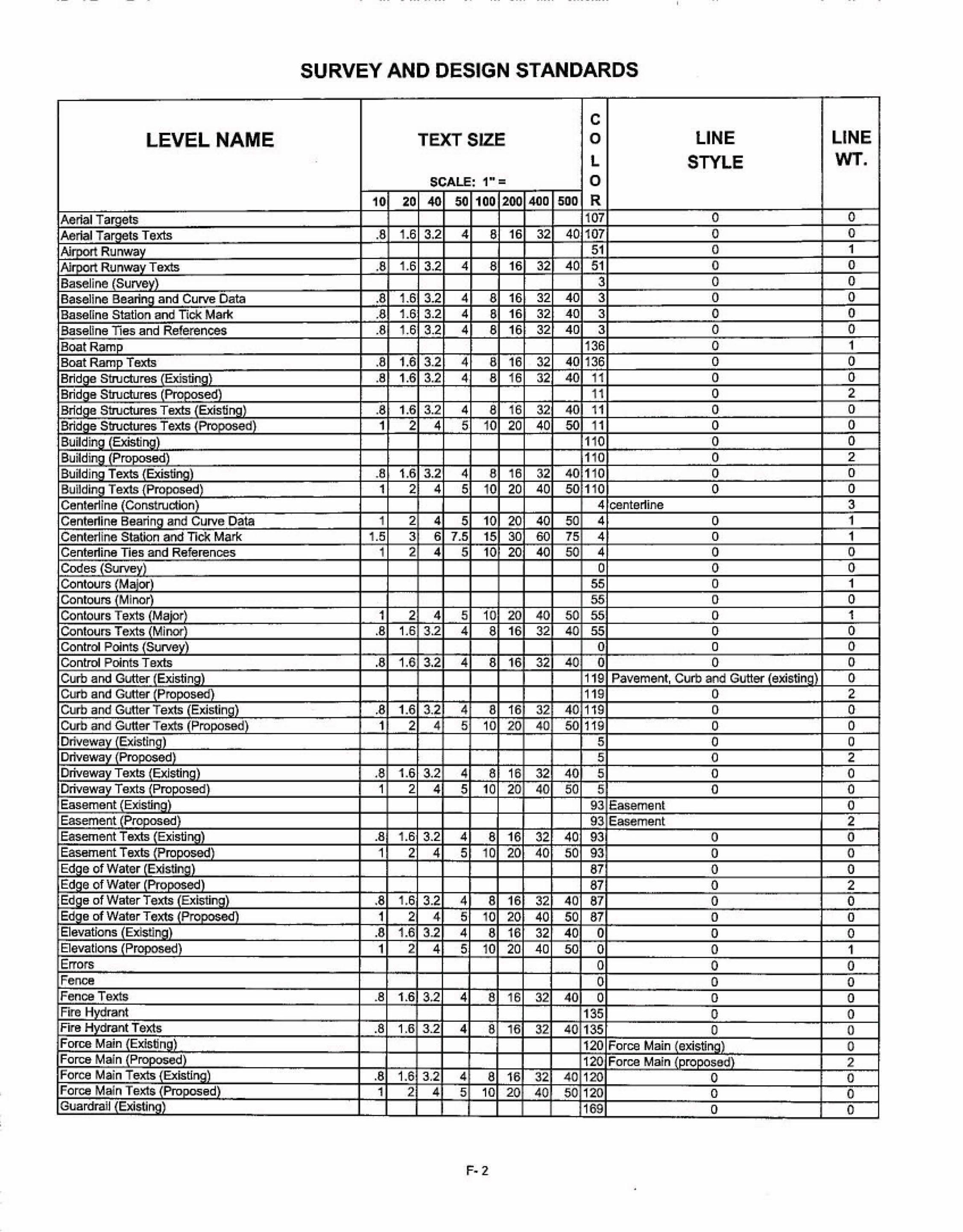
SURVEY AND DESIGN STANDARDS
' c
LEVEL NAME TEXT SIZE '
' 0 LINE ' LINE ' L STYLE WT. ' .
SCALE: 1"= 0 10 20 40 50 100 200 400 sno R
'
0 . Aerial Ta,H'Qts 107 0 '
Aerial Targets Texts .8 1.6 3.2 4 8 16 32 40 107 0 0 Airport Runway 51 0 1
'
1A#vvrt Runway Texts I .8 1.6 3.2 4 8 16 32 40 51 0 0 ' Baseline (Survey) 3 0 0 Baseline Bea.;. ':!:jl and Curve Data .8 1.6 3.2 4 6 16 32 40 3 0 0
· Baseline Station and Tick Mark .8 1.6 3.2 4 8 16 32 40 3 0 0 BaseUne lies and References I .8 1.6 . 3.2 4
' 8 16 32 40 3 0 0
Boat Ramp ' 136 0 1 Boat R..!rr.v Texts .8 1.6 3.2 1 4 8 16 ' 32 40 136 0 0 Bridge structures [t:Xistingl .8 ' 1.6 3.2 4, 8 16 32 40 11 0 0
, Bridge Structures (PtOWcsed) ' 11 0 2 Bridge Structures Texts (Existing) .8 ' 1.6 3.2 4 8 16 3.2 40 11 0 0
. Bridge Structures Texts PtvvOS.ed 1 2 4 5 10 20 40 50 11 0 0 ' ' '
0 Building (Existing) 110 0 '
BuDding (Pro · d) ' 110 0 2 BuDding Texts {Existing) .a 1.6 3£2 4 8 16 32 40 110 0 0 BuUding Texts {Proposed 1 2 4 5 10 20 40 50 110 0 0 Centerline ~ .Construction
'
4 center1ine 3 Centertine Bearing and Curve Data 1 2 4 5 10 20 40 50 4 0 1 Centerline Station and TlCk Mark 1.5 3 6 7.5 15 30 6{) 75 4 0 1 Centerline Ties and References 1 2 4 5 10 2{) 40 50 4 0 0
. Codes (Survey) 0 0 0 Contours Maiot 55 0 1 Contours Minor 55 0 0 Contours Texts 1 Major 1 2 4 5 10 20 40 50 55 0 1 Contours Texts · Minor .8 1.6 3.2 4 8 16 32 40 55 0 0 Control Pojnts (SUNey) 0 0 ' 0 ControJ Points Texts .8 1.6 3.2 4 8 16 32 40 0 0 0 Curb and Gutter (Existing) 119 Pavement, CUrb and Gutter (existing 0 Curb and Gutter (Proposed 119 0 2 Curb and Gutter Texts 1 Existing . .8 1.6 3.2 4 8 16 32 40 119 0 0 CUrb and Gutter Texts 1 Proposed) 1 2 4 5 10 20 40 50 119 0 0 .
Driveway {Existing · 5 0 0 '
'
Driveway Proposed) '
5 '
0 2 Driveway Texts Existing) .8 1.6 3.2 4 a 16 32 40 5 0 ' ' 0 Driveway Texts . Proposed) 1 2 4 5 10
'
'
20 40 50 5 0 0 Easement (Existing) 93 Easement 0 Easement (er,oposed) ! 93 Easement ' 2 Easement Texts (Existing) I .8 1.6 3.2 4 8
'
'
16 32 40. 93 0 0 Easement Texts (Proposed) 1 2 4 5 10 20 40 50 93 0 0 Edge of Water (ExisUng) ' 87 0 0 Edge of Water (Pro ed) ' 87 0 2
'
Edge of WaterTexts.(ExEstmg) I .8 1.6 3.2 · 4 8 16 32 40 87 0 0 Edge o1 Water Texts (Pro ~ 1 2
• 4 5 10 20 40 50 87 0 ' 0
Elevations (Existing) .8 1.6 3.2 4 8 16 32 40 0 0 0 Elevations {Proposed) 1 2 4 5 10 20 40 5{) 0 0 1 Errors 0 0 0
' '
Fenoe 0 0 0 Fence Texts .8 1.6 3.2 4 8 16 32 40 0 0 0 Fire Hydrant
.
135 0 0 Frre Hydrant T&xts .8 1.6 3.2 4 8 16 32 40 135 0 0 Force Main (Existing . 120 Force Main (existing) 0 Force Main (Pr ed 120 Force Main (proposed. 2 '
Force Main Texts (Existing) .8 1.6 3.2 4 8 16 32 40 120 0 0 Force Main Texts LnUIJosed) 1 2 4 5 10 20 40 50 120 0 0 .
GuardraiJ 1 Existing) 169 '
0 0
F-2 •

LEVEL NAME
GuardraH (Proposed) GuardraU Texts (Existing GuardraU Texts (Proposed) Irrigation (Existing) Irrigation (Pro.oosed) Irrigation TeXIs Ex.fsting) Irrigation Texts (Proposed_} Lane line
- . - ~ - -· ·- - -- ~ --
SURVEY AND DESIGN STANDARDS •
TEXT SIZE c 0 LINE LINE
WT. L STYLE SCALE: 1" = 0
10. 20 40 50 100 aoo 400 . 500 R 169 0 2
4 8 16 32 40 169 0 0 1 2 4 5 10 20 40 50 169 0 0
71 Irrigation (exist[!gl;u_ ___ _ _ ,.__o=-· --I 71 Irrigation (proposed) 2
.8 1.6 3.2 4 8 16 32 40 71 0 0 1 2 4 5 10 20 40 50 71 0 0
189 2 1 Levees 22 0 0
~
Levees Texts .8 1.6 3.2 4 8 16 32 40 22 0 0 Lot Une · 33 0 0
.
Lot Une Texts .8 1.6 3.2 4 8 16 32 40 33 0 0 Mailbox 0 0 0 .
Mailbox Texts .8 1.6 3.2 4 8 16 32 40 0 0 0 Mangrove Existing) 146 0 0 Mangrove Proposed) 146 0 2 Mangrove Texts Existing) .8 1.6 3.2 4 6 16 32 40 146 0 0 Mangrove Texts Proposed . 1 2 4 5 10 20 40 50 146 o o Manhole (Existing & Generic field located 88 0 0 Manhole Texts (Existing & Generic) fteld located .8 1.6 3.2 . 4 8 16 32 · 40 88 0 0 Match Line 0 0 1 Match Une Texts 1 2 4 5 1 0 20 40 50 · 0 0 1
. Mise Structures (Existing · 0 0 0 Mise Structures (Proposed 0 0 2 Mise Structures Texts (Existi"!S .8 1.6 3.2 4 8 16 32 40 0 0 0 Mise Structures Texts (Propose~d-.-,) -------+__,;,;1~___;,;..2=-t· ..;;.;.;;4~-::5+-1~0~20~_::4..::::-0~---:=5~0.J--O~. I----------::.o------+-~o~-l
Mise Texts 1 2 4 5 10 20 40 50 0 0 0 Municipal Boundary 165 Municipal Boun y 2 Municipal Boundary Texts . .8 1.6 3~2 4 8 16 32! 40 165 0 0 North Arrow 0 0 1 .. Notes (Surv~} .8 1.6 3.2 4 8 16 32 40 0 o o Pavement Existing) 15 Pavement, Curb and Gutter (existing) 0 Pavement (Proposed 15 0 2 Pavement Texts Existing) .8 1.6 3.2 4 8 16 32 40 15 0 0 Pavement Texts (Proposed . 1 2 4 5 10 20 40 50 15 . 0 0 PGL (Ex1stlng) 102 2 0 PGL (Proposed . 102 0 2 PGL Texts (Exit~ting) .8 1.6 3.2 4 8 16 32 40 102 0 0 PGl Texts Proposed} 1 2 4 5 10 20 40 50 102 0 0 Point Names (Survey} · .8 . 1.6 3.2 4 8 16 32 40 0 0 0 Preliminary Stamp . . 179 · 0 0 Property Comers · 0 0 0
.
Propert\fCorners Texts .8 1.6. 3.2 4 8 16 32 40 0 0 · 0 ProJ)ertv Une_(Boundary) · 175 · 0 3 Property Une Texts (B~undary .8 1.6 3.2 4 8 16 32 40 175 o o Railroad (Exrsting) · 131 o o Railroad tnVj.losed) 131 . 0 2 Raifroad Texts (EXistinaJ .a 1.6 3.2 4 8 16 32 40 131 o o Railroad Texts \huvosedl 1 2 4 5 10 20 40 · 60 131 0 0
.
R~ght-o~Way Texts (Existin.,a~· ;;--. ------+...;·~8~1 .~6r3;;..::.2::t--:4r:-=8+-±16:+-.;;32~40=*-:1~01-· ____ __:O;_ _ _ _ _ -J---!:o:....__.J ~ht-ot.Way Texts (Proposed 1 2 4 5 10 20 40 50 10 0 o Sanitarv Sewer Structures 'Ex'JSting 120 San~ Sewer (existing) o Sanitary Sewer Structures (Proposed) 120 Sanit~ry Sewer [proposed) 2 Sanita_ry Sewer S1ructures Texts 1 Exrstlng) .8 1.6 3.2 · 4 8 16 · 32 40 120 o o Sanitary Sewer Structures Texts (Proposed · 1 2 4 · 5 . 10 20 40 so '120 o o
F- 3

LEVEL NAME
Seale Seawall Seawall Texts Section Line Section Une Texts Secoon Symbols Sjdewatk Existing) Sidewatk Proposed) SJdewalk Texts (Existing Sidewalk Texts (Proposed)
Sign Texts Speed Hump (Existln_g} Speed Hump (Proposed) Speed Hump, Texts (Existing) Speed Hump Texts {Proposed} Storm Dram (Existing Storm Drain (Proposed) Storm Drajn Texts Existing} Stonn Drain Texts CPro d) Street Names Striping Striping Texts Tick Sr• i .bot (Survey) Title Sheet Top ofBank_Toe (Existing) Top of Bank_ Toe (Proposed) Top of Bank_ Toe Texts Existing Top of Bani<_ Toe TeKts . Proposed) Traffic Se ator (Existing) Traffic S ator (Pf; ed) Traffic Separator Texts (Existing) Traffic Separator Texts {Pro ~ . ed · Tree:s Trees (Cogo Points) Trees Texts Utilities Uti6ties Texts Water Structures(Existing) Water Structures (Pr . sed) Water Structures Texts (Existing) Water Structures Texts tProposed) Wetland Boun-'· y (Existing) Weuand Boundary (Proposed) • WeUand Boundary Texts 1 Exis.ting Wetland Boundary Texts(Proposed
- · -· - - · -- · -- ~~ -- ·
SURVEY AND DESIGN STANDARDS
TEXT SIZE c 0 LINE
STYLE L SCALe: 1" = 0
10 20 40 Sf 100 200 400 500 R 1.5 3 6 7.5 15 30 60 75 0 0
161 0 .8 1.6 3.2 4 8 16 32 40 161 0
139 Section line .8 1.6 3.2' 4 8 16 32 40 139 0
139 0 163 0 163 0
.8 1.6 3.2 4 8 16 32 40 163 0 1 2 4 5 10 20 40 50 163 0
0 0 .8 1.6 3.2 4 8 16 32 40 0 0
158 5 158 0
.8 1.6 3.2 4 8 16 32 40 158 0 ~
1 2 4 5 1.0 20 40 50 158 0 92 Storm Oraln (existrng) 92 Stonn Drain (proposed)
.8 1.6 3.2 4 8 16 32 4{) 92 0 1 2 4 5 10 20 40 50 92 0 2 4 8 10 20 40 80 100 0 0
80 2 1 2 4 5 10 20 40 50 so 0
0 0 0 0
.100 0 100 0
.8 1.6 3.2 4 8 16 . 32 40 100 0 ~ ~
1 2 4 5 10 20 40 50 100 0 ~
12 0 12 0
.. 8 1.6 3.2 4 8 16 32 4() 12 0 1 2 4 5 10 20 40 50 12 0
130 0 .8 1 .. 6 3.2 4 8 16 32 40 130 0 .8 1.6 3.2 4 8 t 6 32 40 130 0
140 0 .a 1.6 3.2 4 s 16 32 4o 140 o
135 Water Line (existing 135 Water Une {proposed
.8 1.6 3.2 4 8 16 32 40 135 0 1 2 4 5 10 2{) 40 50 136 0
114 0 114 0
.8 1.6 3.2 4 8 16 32 40 114 0 1 2 4 5 10 20 40 50 114 0
F-4
LINE WT.
1 0 0 0 0 1 0 2 0 0 0
~
0 0 2 0 0 0 2 0 0 1 3 0 0 1 0 2 0 0 0 2 0 0 0 0 0 0 0 0 ~
2 0 0 0 2 0 0
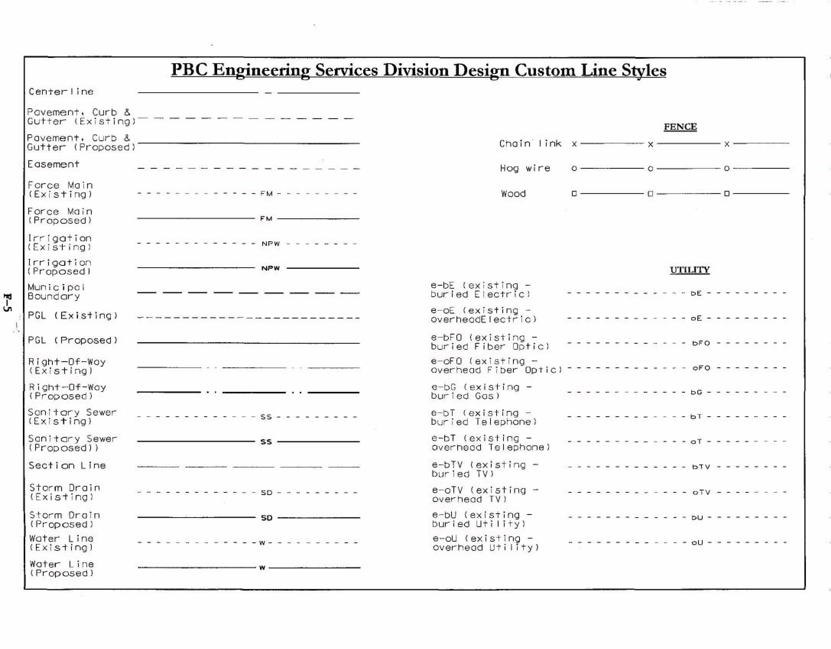
~
~
•
PBC Engineering Services D.iYi~ion Design Custom~.ltine Styles Center I i ne - --------------Pa vement , Curb & Gut ter- <Ex ist T ng )- - ---- - - - - -- - -Pavement, Curb & Gutte r (Pr oposed)
·Easement
For ce Ma in c Ex i s 't i ng )
Force Main ( Pr-oposed >
l r r i got i on CEx i s't i ng ) I I I T gat ion (Pr opo s ed 1
Mun i c i p o I Boundary
- - -- - - -- -
- - - - - - - - - - - - - F M - - - - - - - - -
------------------ F' M -------
- - - - - - - - - - - - - N P W -. - - --- ·- -
NPW
, PGL ( Ex i sting) - - - - - - ------- --- ----------I ·. .. ·,
PGL C Pr op os ed >
R i ght-Of - Woy < E x i s 't i ng )
Ri gh-t-Of - Way <Proposed )
Son i t ory Sewer <E x is-t ing >
Son i t a r y Sewer (Proposed) >
Section Line
Stor m Or o i n · < E x i s -t i ng l
Storm Or o Tn <Praposed )
Water Line (Exi s +i ng l
Water L i ne <Pr op osed )
----- . ' ------ • •
- - - - - - - - - - - - - 55 - - - - - - - - -
-------------------- s s --------------
- - - - - - - - - - - - - so - - - - - - - - -
-------------------- so --------------
- - - - - - - - -- - - - w-- - --- -- - -
- ------------w--- -----
FENCE
Cho rn · 1 i nk x ---~~ x ----- x --- ---
Hog wire
Wood
e - bE {ex is t ing -burl ed E lectricJ
e - oE <ex is t i ng -overhe odEiectrlc )
e-bFO (exi sti ng -buri e d F iber Opt i cl
e - oFO ( e x isting -overhead Fi ber Optlcl
e - bG <ex i s ti ng -bur led Gos )
e - bT <exist ing -buried Te lephone )
e - bT <ex ist ing -overhead Te lephone)
e-bTV ( e x isting burl ed TV >
e - oTV <ex isting -overhead TV} e - bU <ext str ng -bur ied Ut i I i t y l e - ou <exi s t ing -overhe ad Ut i l i t y)
0 - - - -- 0 --- - - 0-----
o-----o----- 0-----
UTlLITY
- - - - - - - - - - - - - bE - - - - - - - - -
- - - - - - - - - - - - - o E - - - - - - - - -
- - - - - - - - - -- - - - b F O - - - - - - - -
- - - - - - - - - - - - - o FO· - - - - - - - -
- - - - - - - - - - - - - bC - - - - - - - - -
- - - - - - - - - - - - - b T - - - - - - - - -
- - - - - - - - - - - - - o T - - - - - - - - -
- .... - - - - - - - - - - - b T V - - - - - - - -
- - - - - - - - - - - - - o TV - - - - - - - -
- - - - - - - - - - - - - ou - - - - - - - - -
- - - - - - - - - - - - - ou - - - - - - - - -

APPENDIXG
S.,\gnal Design Submittals
Traffic Signal Design will start when all right-of-way and lane g~ometrics are established. Accordingly the first signal design submittal will be at the 65% of roadway submittal Traffic signal design submittal included in the 65% roadway submittal is also considered 65% signal submittal. The 65o/o signal design submittal will include:
--
--
-
----
---
-
All utilities, including overhead, underground and clearances, identified and shown on the signal plans. Verification of all utility calls. Right-of-way, complete road geometries, and pavement markings shall be included in all signal plan submittal as part of the signal plan. All pole locations Mast Ann lengths identified for mast ann signals All signal head locations and alignment All Illuminated Street Name Signs Controller location Loops locations Pull-box locations Locations of signal power source Signal phasing · Turning movement counts Pedestri~ equipment including pedestrian heads, push buttons and signs Traffic Signal General Notes Mast ann detai 1 and layout sheet
All conunents on the 65o/o shall be addressed, plans re-submitted and approved before 95% plan submittal.
The 95% submittal will include: - Structural analysis - Details sheets - Estimated quantities
* All utilities identified and shown on signal plans at all submittals.
F:\TRAFFIC\FNJ\StmGWs\Sgn1DsgnS.bmrl$_ 14Sep03.doc
G-1