table of contents page - dodge official site table of contents page ... 8 maintenance schedules ......
TRANSCRIPT

TABLE OF CONTENTSSECTION PAGE
1 INTRODUCTION . . . . . . . . . . . . . . . . . . . . . . . . . . . . . . . . . . . . . . . . . . . . . . . . . . . . . . . . . . . . . 3
2 THINGS TO KNOW BEFORE STARTING YOUR VEHICLE . . . . . . . . . . . . . . . . . . . . . . . . . . . 7
3 UNDERSTANDING THE FEATURES OF YOUR VEHICLE . . . . . . . . . . . . . . . . . . . . . . . . . . . . 55
4 INSTRUMENT PANEL AND CONTROLS . . . . . . . . . . . . . . . . . . . . . . . . . . . . . . . . . . . . . . . . . 93
5 STARTING AND OPERATING . . . . . . . . . . . . . . . . . . . . . . . . . . . . . . . . . . . . . . . . . . . . . . . . 141
6 WHAT TO DO IN EMERGENCIES . . . . . . . . . . . . . . . . . . . . . . . . . . . . . . . . . . . . . . . . . . . . . 207
7 MAINTAINING YOUR VEHICLE . . . . . . . . . . . . . . . . . . . . . . . . . . . . . . . . . . . . . . . . . . . . . . 219
8 MAINTENANCE SCHEDULES . . . . . . . . . . . . . . . . . . . . . . . . . . . . . . . . . . . . . . . . . . . . . . . . 261
9 IF YOU NEED CONSUMER ASSISTANCE . . . . . . . . . . . . . . . . . . . . . . . . . . . . . . . . . . . . . . . 279
10 INDEX . . . . . . . . . . . . . . . . . . . . . . . . . . . . . . . . . . . . . . . . . . . . . . . . . . . . . . . . . . . . . . . . . . . 287
1
2
3
4
5
6
7
8
9
10


INTRODUCTION
CONTENTS
m Introduction . . . . . . . . . . . . . . . . . . . . . . . . . . . 4
m How To Use This Manual . . . . . . . . . . . . . . . . . 4
m Warnings And Cautions . . . . . . . . . . . . . . . . . . 5
m Vehicle Identification Number . . . . . . . . . . . . . . 5
m Vehicle Modifications / Alterations . . . . . . . . . . 5
1

INTRODUCTIONThis manual has been prepared with the assistance ofservice and engineering specialists to acquaint you withthe operation and maintenance of your new vehicle. It issupplemented by a Warranty Information Booklet andvarious customer oriented documents. You are urged toread these publications carefully. Following the instruc-tions and recommendations in this manual will helpassure safe and enjoyable operation of your vehicle.
NOTE: After you read the manual, it should be storedin the vehicle for convenient reference and remain withthe vehicle when sold, so that the new owner will beaware of all safety warnings.
When it comes to service, remember that your dealerknows your vehicle best, has the factory-trained techni-cians and genuine Mopart parts, and is interested inyour satisfaction.
WARNING!
Engine exhaust, some of its constituents, and certainvehicle components contain or emit chemicalsknown to the State of California to cause cancer andbirth defects or other reproductive harm. In addition,certain fluids contained in vehicles and certain prod-ucts of component wear contain or emit chemicalsknown to the State of California to cause cancer andbirth defects or other reproductive harm.
HOW TO USE THIS MANUALConsult the table of contents to determine which sectioncontains the information you desire.
The detailed index, at the rear of this manual, contains acomplete listing of all subjects.
4 INTRODUCTION

WARNINGS AND CAUTIONSThis manual contains WARNINGS against operatingprocedures which could result in an accident or bodilyinjury. It also contains CAUTIONS against procedureswhich could result in damage to your vehicle. If you donot read this entire manual you may miss importantinformation. Observe all Warnings and Cautions.
VEHICLE IDENTIFICATION NUMBERThe vehicle identification number (VIN) is found on astamped plate located on the left front corner of theinstrument panel pad, visible from outside of the vehiclethrough the windshield. This number also appears on theAutomobile Information Disclosure Label affixed to awindow on your vehicle. Save this label for a convenientrecord of your vehicle identification number and optionalequipment.
NOTE: It is illegal to remove the VIN plate.
VEHICLE MODIFICATIONS / ALTERATIONS
WARNING!
Any modifications or alterations to this vehiclecould seriously affect its roadworthiness and safetyand may lead to an accident resulting in seriousinjury or death.
INTRODUCTION 5
1


THINGS TO KNOW BEFORE STARTING YOUR VEHICLE
CONTENTS
m A Word About Your Keys . . . . . . . . . . . . . . . . . 9
▫ Key-In-Ignition Reminder . . . . . . . . . . . . . . . . 9
▫ Sentry Key — If Equipped . . . . . . . . . . . . . . . . 9
m Ignition And Steering Lock — If Equipped . . . .11
▫ Manual Transmissions . . . . . . . . . . . . . . . . . . .11
▫ Automatic Transmissions . . . . . . . . . . . . . . . . .12
m Illuminated Entry . . . . . . . . . . . . . . . . . . . . . . .12
▫ Vehicles Equipped With Power Door Locks . . . .12
m Door Locks . . . . . . . . . . . . . . . . . . . . . . . . . . .13
▫ Manual Locks . . . . . . . . . . . . . . . . . . . . . . . . .13
▫ Power Door Locks — If Equipped . . . . . . . . . .14
▫ Child Protection Door Lock . . . . . . . . . . . . . . .16
m Remote Keyless Entry — If Equipped . . . . . . . .17
▫ To Unlock The Doors (Four Door Vehicles) . . . .17
▫ To Lock The Doors . . . . . . . . . . . . . . . . . . . . .18
▫ Using The Panic Alarm . . . . . . . . . . . . . . . . . .19
▫ Programming Additional Transmitters . . . . . . . .19
▫ General Information . . . . . . . . . . . . . . . . . . . .20
▫ Transmitter Battery Service . . . . . . . . . . . . . . .21
m Security Alarm System — If Equipped . . . . . . .21
▫ To Set The Alarm . . . . . . . . . . . . . . . . . . . . . .21
▫ To Disarm The System . . . . . . . . . . . . . . . . . . .22
2

m Windows . . . . . . . . . . . . . . . . . . . . . . . . . . . . .22
▫ Power Windows — If Equipped . . . . . . . . . . . .22
▫ Sliding Rear Window—If Equipped . . . . . . . . .23
▫ Club Cab Vented Quarter Window . . . . . . . . . .24
▫ Wind Buffeting . . . . . . . . . . . . . . . . . . . . . . . .24
m Occupant Restraints . . . . . . . . . . . . . . . . . . . . .24
▫ Lap/Shoulder Belts . . . . . . . . . . . . . . . . . . . . .25
▫ Adjustable Upper Shoulder Belt Anchorage . . . .29
▫ Seat Belt Pretensioners—Quad Cab Only . . . . . .29
▫ Front Lap Belts . . . . . . . . . . . . . . . . . . . . . . . .30
▫ Seat Belts And Pregnant Women . . . . . . . . . . . .30
▫ Seat Belt Extender . . . . . . . . . . . . . . . . . . . . . .31
▫ Driver And Right Front Passenger SupplementalRestraint System—Airbag . . . . . . . . . . . . . . . .31
▫ Child Restraint . . . . . . . . . . . . . . . . . . . . . . . .38
m Engine Break-In Recommendations . . . . . . . . . .52
m Safety Tips . . . . . . . . . . . . . . . . . . . . . . . . . . . .53
▫ Exhaust System . . . . . . . . . . . . . . . . . . . . . . .53
▫ Safety Checks You Should Make Inside TheVehicle . . . . . . . . . . . . . . . . . . . . . . . . . . . . . .54
▫ Safety Checks You Should Make Outside TheVehicle . . . . . . . . . . . . . . . . . . . . . . . . . . . . . .54
8 THINGS TO KNOW BEFORE STARTING YOUR VEHICLE

A WORD ABOUT YOUR KEYSThe double sided keys may be inserted into the lockswith either side up. The keys for your new vehicle areenclosed in a plastic bag with a bar code label affixed tothe front. The bar code can be used to order duplicatekeys from your dealer or a locksmith. If you receivedyour keys without the bag, ask your dealer to give youthe number.
Key-In-Ignition ReminderIf you open the driver’s door when the key is in theignition lock, a continuous chime will sound to remindyou to remove the key.
CAUTION!
An unlocked vehicle is an invitation to thieves.Always remove the key from the ignition and lockall the doors when leaving the vehicle unattended.
SENTRY KEY — IF EQUIPPEDWith this system, an electronically coded ignition keysends a signal to the vehicle electronics. If the electronicsrecognizes the signal, the vehicle will start and continueto run. If the system does not recognize the signal, thevehicle will start and run for 2 seconds, then shut off.After six unsuccessful attempts at starting, the systemwill shut down until the correct key is used.
NOTE: The Sentry Key Immobilizer System is notcompatible with remote starting systems. Use of thesesystems may result in vehicle starting problems and aloss of security protection. Additional Sentry Keys orMobil Speed-pass™ devices held against or immediatelyadjacent to the ignition key when starting the engine maycause vehicle starting problems. If a problem occurs,remove the Sentry Key from the key-ring and attempt tostart the vehicle again. Pagers, cell phones, walkman, etc.will have no effect on this system.
The 9Security Light9 will illuminate for about 3 secondswhen the ignition switch is first turned to the ONposition. If the vehicle electronics do not receive a validsignal from the ignition key, the 9Security Light9 will flash
THINGS TO KNOW BEFORE STARTING YOUR VEHICLE 9
2

continuously to signal that the vehicle has been immobi-lized. If the 9Security Light9 remains on during vehicleoperation, it indicates a fault in the system electronics. Ifthis option was ordered, all of the keys provided withyour new vehicle have been programmed to the vehicleelectronics.
Replacement Keys
NOTE: Only keys that have been programmed to thevehicle electronics can be used to start the vehicle. Oncea Sentry Key has been programmed to a vehicle, it cannotbe programmed to any other vehicle.
At the time of purchase, the original owner is providedwith a four digit PIN number. This number is requiredfor dealer replacement of keys. Duplication of keys maybe performed at an authorized dealer or by using theCustomer Key Programming procedure. This procedureconsists of programming a blank key to the vehicleelectronics. A blank key is one which has never beenprogrammed and needs to be cut.
NOTE: When having the Sentry Key System serviced,bring all vehicle keys to the dealer.
Customer Key ProgrammingYou can program new keys to the system if you have twovalid keys by doing the following:
1. Insert the first valid key into the ignition and turn theignition to the ON position for at least 3 seconds but nolonger than 15 seconds. Turn the ignition back to the OFFposition and remove the first key.
2. Insert the second valid key and switch the ignition tothe ON position within 15 seconds. After 10 seconds, achime will sound and the 9Security Light9 will begin toflash. Turn the ignition back to the OFF position andremove the second key.
3. Insert a blank Sentry Key into the ignition and switchthe ignition to the ON position within 60 seconds ofhaving removed the second key. After 10 seconds, asingle chime will sound. The 9Security Light9 will stopflashing, then turn on for 3 seconds; then turn off.
The new Sentry Key has been programmed. Repeat thisprocess to program up to a total of 8 keys.
10 THINGS TO KNOW BEFORE STARTING YOUR VEHICLE

General InformationThis device complies with part 15 of FCC rules and withRS-210 of Industry Canada. Operation is subject to thefollowing conditions:
1. This device may not cause harmful interference.
2. This device must accept any interference that may bereceived including interference that may cause undesiredoperation.
NOTE: Changes or modifications not expressly ap-proved by the party responsible for compliance couldvoid the user’s authority to operate the equipment.
IGNITION AND STEERING LOCK — IF EQUIPPED
Manual TransmissionsDepress and hold the release button located between theignition switch and the instrument panel. Turn the igni-tion key to LOCK and remove the key.
Manual Transmissions
THINGS TO KNOW BEFORE STARTING YOUR VEHICLE 11
2

Automatic TransmissionsIn the LOCK position, the steering and ignition systemsare locked to provide antitheft protection for your ve-hicle. It may be difficult to turn the key from the LOCKposition when starting your vehicle. Move the steeringwheel left and right while turning the key until it turnseasily. The key can be inserted or withdrawn only in theLOCK position. Push in on the key in the ignition lockcylinder to rotate to the LOCK position.
NOTE: On vehicles equipped with an automatic trans-mission, the key cannot be turned to LOCK until theselector is in the PARK position. Do not attempt to pullthe shift lever out of PARK after the key is in the LOCKposition.
ILLUMINATED ENTRY
Vehicles Equipped With Power Door LocksAll interior lights will illuminate in the vehicle when thedoors are unlocked using the key fob, when any door isopened or, if equipped with security, when the door keycylinder is turned to the unlock position. Vehiclesequipped with a cargo lamp will turn the cargo lamp onfor 30 seconds when the doors are unlocked using the keyfob.
The interior lights will remain on for 30 seconds after thelast door is closed, or until all doors are closed and eitherthe ignition is turned to the ON position or a key fobLOCK button is pressed.
Automatic Transmissions
12 THINGS TO KNOW BEFORE STARTING YOUR VEHICLE

There is also a battery saver feature that will turn theinterior lights off after 15 minutes if the ignition is OFFand a door is left open or the dimmer control is in theinterior lights ON position or cargo light ON position.
DOOR LOCKS
Manual LocksFront doors may be locked, sliding the lock knob rear-ward. When the orange indicator is visible the lock knobis in the unlocked position.
Both doors may be opened with the inside door handlewithout sliding the lock knob forward. Doors lockedbefore closing will remain locked when closed.
The ignition key will unlock all the locks on your vehicle.
WARNING!
For personal security and safety in the event of anaccident, lock the vehicle doors when you drive aswell as when you park and leave the vehicle.
WARNING!
When leaving the vehicle always remove the keyfrom the ignition lock, and lock your vehicle. Do notleave children unattended in the vehicle, or withaccess to an unlocked vehicle. Unsupervised use ofvehicle equipment may cause severe personal inju-ries and death.
THINGS TO KNOW BEFORE STARTING YOUR VEHICLE 13
2

Power Door Locks — If EquippedVehicles equipped with power door locks can be lockedor unlocked from inside by either the use of the door lockswitches located on the front doors or by pressing theLOCK or UNLOCK buttons on the Remote Keyless Entrykey fob.
As a safety feature the doors will not lock when using thedoor lock switches during the following conditions:
1. The driver’s door is open while the key is in theignition.
2. The driver’s door is open while the headlight switch isON.
14 THINGS TO KNOW BEFORE STARTING YOUR VEHICLE

Central Locking — If EquippedVehicles with security will have a feature called 9CentralLocking.9 When the key is placed in the door cylinderand turned to the 9Unlock9 position, the security will bedisarmed, the illuminated entry will be turned on andthat door will be mechanically unlocked. If the key isonce again turned to the unlock position within 5 secondsof the first unlock, the remaining doors will unlock. If thekey is turned to the 9Lock9 position while all doors areclosed, illuminated entry will be canceled, security willbegin arming, and all doors will lock.
Automatic Door LocksIf this feature is enabled, your door locks will lockautomatically when the vehicle’s speed exceeds 15 mph(24 km/h).
This feature is enabled when your vehicle is shippedfrom the assembly plant and can be disabled by using thefollowing procedure:
1. Enter your vehicle and close all doors.
2. Fasten your seat belt (Fastening the seat belt willcancel any chiming that may confuse you during thisprogramming procedure).
3. Place the key into the ignition.
4. Within 10 seconds cycle the key from the OFF positionto the ON position four times; ending in the OFF position( Do not start the engine ).
5. Within 30 seconds, press the driver’s door lock switchin the LOCK direction.
6. A single chime will be heard to indicate the feature hasbeen disabled.
7. To reactivate this feature, repeat the above steps.
8. If a chime is not heard, program mode was canceledbefore the feature could be disabled. If necessary, repeatthe above procedure.
THINGS TO KNOW BEFORE STARTING YOUR VEHICLE 15
2

Child Protection Door LockTo provide a safer environment for small children ridingin the rear seats, the rear doors are equipped with a childprotection door lock system.
This label is located near thelock lever.
WARNING!
Avoid trapping anyone in the vehicle in a collision.Remember that the rear doors can only be openedfrom the outside when the child protection locks areengaged.
16 THINGS TO KNOW BEFORE STARTING YOUR VEHICLE

REMOTE KEYLESS ENTRY — IF EQUIPPED
This system allows you to lock or unlock the doors fromdistances up to about 23 feet (7 meters) using a hand heldradio transmitter. The transmitter need not be pointed atthe vehicle to activate the system.
To unlock the doors (four door vehicles):Press and release the UNLOCK button on the key fobonce to unlock only the driver’s door or twice to unlockall the doors. When the UNLOCK button is pressed, the
illuminated entry will initiate, the parking lights willflash on twice and if installed, the cargo lamp will turn onfor 30 seconds.
The system can be programmed to unlock all the doorsupon the first UNLOCK button press by using thefollowing procedure:
1. Enter your vehicle and close all doors.
2. Fasten your seat belt. (Fastening the seat belt willcancel any chiming that may confuse you during thisprogramming procedure).
3. Place the key into the ignition.
4. Within 10 seconds cycle the key from the OFF positionto the ON position four times; ending in the ON position( Do not start the engine ).
5. Within 30 seconds, press the driver’s door lock switchin the UNLOCK direction.
6. A single chime will be heard to indicate the feature hasbeen disabled.
7. To reactivate this feature, repeat the above steps.
THINGS TO KNOW BEFORE STARTING YOUR VEHICLE 17
2

8. If a chime is not heard, program mode was canceledbefore the feature could be disabled. If necessary, repeatthe above procedure.
NOTE: All two-door vehicles will be shipped from theassembly plant with this feature disabled. If this feature isenabled on a two door vehicle, a single UNLOCK buttonpress will initiate the illuminated entry only - none of thedoors will unlock. If the UNLOCK button is pressed asecond time within 4 seconds of the first, all doors willunlock.
To lock the doors:Press and release the LOCK button on the transmitter tolock all doors. If the ignition is OFF, when the doors arelocked, the parking lights will flash on once and the hornwill chirp once.
The horn chirp feature will be shipped from the assemblyplants activated. If desired this feature can be disabled byusing the following procedure:
1. Enter your vehicle and close all doors.
2. Fasten your seat belt (Fastening the seat belt willcancel any chiming that may confuse you during thisprogramming procedure).
3. Place the key into the ignition.
4. Turn the ignition to the ON position ( Do not start theengine ).
5. Press and hold the LOCK button on the key fob.
6. After holding the LOCK button for four seconds, alsopress the PANIC button within 6 seconds.
7. When a single chime is heard, release both buttons.
8. Turn the ignition OFF to test the horn chirp feature.
9. To reactivate this feature, repeat the above steps.
10. If a chime is not heard, program mode was canceledbefore the feature could be disabled. If necessary, repeatthe above procedure.
18 THINGS TO KNOW BEFORE STARTING YOUR VEHICLE

Using the Panic AlarmTo activate the Panic mode while the ignition is OFF pressand release the PANIC button on the transmitter once.When the Panic mode is activated, the interior lights willilluminate, the headlamps and parking lights will flash,and the horn will sound.
To cancel the Panic mode press and release the PANICbutton on the transmitter a second time. Panic mode willautomatically cancel after 3 minutes or if the vehicle isstarted and exceeds 15 mph (24 km/h). During the PanicMode, the door locks and remote keyless entry systemswill function normally. Panic mode will not disarm thesecurity system on vehicles so equipped.
Programming Additional TransmittersVehicles with the keyless entry option will be shippedfrom the assembly plants with two key fob transmittersprogrammed only for that vehicle. A total of four fobs canbe programmed for your vehicle. Additional fobs can beprogrammed to your vehicle through the use of a cur-rently programmed fob.
NOTE: When entering program mode using that fob,all other programmed fobs will be erased and you willhave to reprogram them for your vehicle.
Use the Following procedure to program additional keyfobs:
1. Enter your vehicle and close all doors.
2. Fasten your seat belt (Fastening the seatbelt will cancelany chiming that may confuse you during this program-ming procedure).
3. Place the key into the ignition.
4. Turn the ignition to the ON position ( Do not start theengine ).
5. Press and hold the UNLOCK button on the key fob.
6. After holding the UNLOCK button for four seconds,also press the PANIC button within 6 seconds.
7. Release both buttons and a single chime will be heard.The chime is an indication that you have successfullyentered program mode. All fobs that are to be pro-grammed must be done so within 30 seconds of when thechime was heard.
THINGS TO KNOW BEFORE STARTING YOUR VEHICLE 19
2
8. Using the fob to be programmed, press and releaseboth the LOCK and UNLOCK buttons, simultaneously.
9. A single chime will be heard.
10. Within four seconds of hearing the chime, press andrelease either the LOCK or UNLOCK button on the fob.
11. Repeat steps 8 through 10 to program up to twoadditional fobs.
12. Your vehicle will remain in program mode up to 30seconds from when the original chime was heard. After30 seconds, all programmed fobs function normally.
NOTE: If you do not have a programmed transmitter,contact your dealer for details.
General InformationThis device complies with part 15 of FCC rules and withRS-210 of Industry Canada. Operation is subject to thefollowing conditions:
1. This device may not cause harmful interference.
2. This device must accept any interference that may bereceived including interference that may cause undesiredoperation.
NOTE: Changes or modifications not expressly ap-proved by the party responsible for compliance couldvoid the user’s authority to operate the equipment.
If your Keyless Entry Transmitter fails to operate from anormal distance, check for these two conditions.
1. Weak batteries in transmitter. The expected life of thebatteries is from one to two years.
2. Closeness to a radio transmitter such as a radio stationtower, airport transmitter, and some mobile or CB radios.
20 THINGS TO KNOW BEFORE STARTING YOUR VEHICLE

Transmitter Battery Service
The recommended replacement battery is 2016.
NOTE: Do not touch the battery terminals that are onthe back housing or the printed circuit board.
1. With transmitter buttons facing down, use a flat bladeor dime to pry the two halves of the transmitter apart.Make sure not to damage the rubber gasket duringremoval.
2. Remove and replace the batteries. Avoid touching thenew batteries with your fingers. Skin oils may causebattery deterioration. If you touch a battery, clean it withrubbing alcohol.
3. To reassemble the transmitter case snap the two halvestogether. Make sure there is an even gap between the twohalves. Test transmitter operation.
SECURITY ALARM SYSTEM — IF EQUIPPEDThis system monitors the vehicle doors and ignition forunauthorized operation. When the alarm is activated, thesystem provides both audible and visual signals. Thehorn will sound repeatedly for 3 minutes and the head-lights and security light in the instrument cluster willflash for an additional 15 minutes. The engine will notrun until the system is disarmed.
To Set the Alarm:The alarm will set when you use the power door locks,turn the key in the door lock cylinder, or use the KeylessEntry transmitter to lock the doors. After all the doors arelocked and closed the SECURITY light in the instrumentcluster will flash rapidly to signal that the system is
THINGS TO KNOW BEFORE STARTING YOUR VEHICLE 21
2

arming. The security light in the instrument panel clusterwill flash rapidly for about 15 seconds to indicate that thealarm is being set. After the alarm is set, the security lightwill flash at a slower rate to indicate that the system isarmed.
NOTE: If the SECURITY light stays on continuouslyduring vehicle operation, have the system checked byyour dealer.
To Disarm the System:Use the Keyless Entry transmitter or the key to turn thedoor locks to the unlock position. If something hastriggered the system in your absence, the horn will soundthree times when you unlock the doors. Check thevehicle for tampering.
The Security system will also disarm, if the vehicle isstarted with a programmed Sentry Key. If an unpro-grammed Sentry Key is used to start a vehicle, the enginewill run for 2 seconds and then the security alarm will beinitiated. To exit alarming mode, press the RKE Unlockbutton, unlock the doors using the key cylinder, or startthe vehicle with a programmed Sentry Key.
The Security Alarm System is designed to protect yourvehicle; however, you can create conditions where thesystem will arm unexpectedly. If you remain in thevehicle and lock the doors with the transmitter, the alarmwill sound when you pull the door handle to exit. Youmay also accidentally disarm the system by unlockingany door with the door key and then locking it. The doorwill be locked but the Security Alarm will not arm.
WINDOWS
Power Windows — IF Equipped
22 THINGS TO KNOW BEFORE STARTING YOUR VEHICLE

The control on the left front door panel has up-downswitches that give you fingertip control of all powerwindows. There is a single opening and closing switch onthe front passenger door for passenger window controland on the rear doors of Quad Cab models. The windowswill operate only when the ignition switch is turned tothe ON position.
Auto DownThe driver’s window switch has an Auto Down feature.Press the window switch past the detent, release, and thewindow will go down automatically.
Window Lockout SwitchThe window lockout switch on the driver’s door allowsyou to disable the window control on the other doors. Todisable the window controls on the other doors, press thewindow lock button. To enable the window controls,press the window control button again.
Sliding Rear Window—If EquippedA locking device in the center of the window helps toprevent entry from the rear of the vehicle. Squeeze thelock to release the window.
THINGS TO KNOW BEFORE STARTING YOUR VEHICLE 23
2

Club Cab Vented Quarter WindowThe Club Cab is equipped with rear quarter windowsthat open out. Pull the window latch toward you tounlock, and push out on the window. Press the latchstraight to secure the window in an open position.
WIND BUFFETINGWind buffeting can be described as the perception ofpressure on the ears or a helicopter type sound in theears. Your vehicle may exhibit wind buffeting with thewindows down, or the sunroof (if so equipped) in certainopen or partially open positions. This is a normal occur-rence and can be minimized. If the buffeting occurs withthe rear windows open, open the front and rear windowstogether to minimize the buffeting. If the buffeting occurswith the sunroof open, adjust the sunroof opening tominimize the buffeting.
OCCUPANT RESTRAINTSSome of the most important safety features in yourvehicle are the restraint systems. These include the frontand rear seat belts for the driver and all passengers, andfront airbags for both the driver and front passenger. Ifyou will be carrying children too small for adult-sizebelts, your seat belts also can be used to hold infant andchild restraint systems.
Please pay close attention to the information in thissection. It tells you how to use your restraint systemproperly to keep you and your passengers as safe aspossible.
WARNING!
In a collision, you and your passengers can suffermuch greater injuries if you are not properly buck-led up. You can strike the interior of your vehicle orother passengers, or you can be thrown out of thevehicle. Always be sure you and others in yourvehicle are buckled up properly.
24 THINGS TO KNOW BEFORE STARTING YOUR VEHICLE

Buckle up even though you are an excellent driver, evenon short trips. Someone on the road may be a poor driverand cause a collision that includes you. This can happenfar away from home or on your own street.
Research has shown that seat belts save lives, and thatthey can reduce the seriousness of injuries in a collision.Some of the worst injuries happen when people arethrown from the vehicle. Seat belts reduce the possibilityof ejection and the risk of injury caused by striking theinside of the vehicle. Everyone in a motor vehicle shouldbe belted at all times.
Lap/Shoulder BeltsThe outboard front and rear seats of your vehicle havecombination lap/shoulder belts. The belt webbing retrac-tor is designed to lock during very sudden stops orcollisions. This feature allows the shoulder part of thebelt to move freely with you under normal conditions.But in a collision, the belt will lock and reduce the risk ofyour striking the inside of the vehicle or being thrownout.
WARNING!
It is extremely dangerous to ride in a cargo area,inside or outside of a vehicle. In a collision, peopleriding in these areas are more likely to be seriouslyinjured or killed.
Do not allow people to ride in any area of yourvehicle that is not equipped with seats and seat belts.
Be sure everyone in your vehicle is in a seat andusing a seat belt properly.
THINGS TO KNOW BEFORE STARTING YOUR VEHICLE 25
2

WARNING!
• Wearing a seat belt incorrectly is dangerous. Seatbelts are designed to go around the large bones ofyour body. These are the strongest parts of yourbody and can take the forces of a collision thebest. Wearing your belt in the wrong place couldmake your injuries in a collision much worse. Youmight suffer internal injuries, or you could evenslide out of part of the belt. Follow these instruc-tions to wear your seat belt safely and to keepyour passengers safe, too.
• Two people should never be belted into a singleseat belt. People belted together can crash into oneanother in an accident, hurting one another badly.Never use a lap/shoulder belt or a lap belt formore than one person, no matter what their size.
Lap/Shoulder Belt Operating Instructions
1. Enter the vehicle and close the door. Sit back andadjust the seat.
2. The seat belt latch plate is above the back of the frontseat, next to your arm in the rear seat. Grasp the latchplate and pull out the belt. Slide the latch plate up thewebbing as far as necessary to allow the belt to go aroundyour lap.
26 THINGS TO KNOW BEFORE STARTING YOUR VEHICLE
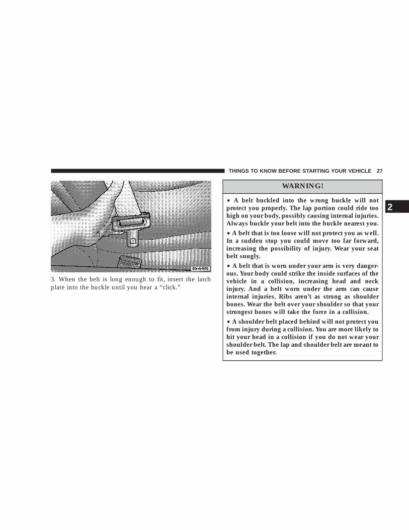
3. When the belt is long enough to fit, insert the latchplate into the buckle until you hear a “click.”
WARNING!
• A belt buckled into the wrong buckle will notprotect you properly. The lap portion could ride toohigh on your body, possibly causing internal injuries.Always buckle your belt into the buckle nearest you.• A belt that is too loose will not protect you as well.In a sudden stop you could move too far forward,increasing the possibility of injury. Wear your seatbelt snugly.• A belt that is worn under your arm is very danger-ous. Your body could strike the inside surfaces of thevehicle in a collision, increasing head and neckinjury. And a belt worn under the arm can causeinternal injuries. Ribs aren’t as strong as shoulderbones. Wear the belt over your shoulder so that yourstrongest bones will take the force in a collision.• A shoulder belt placed behind will not protect youfrom injury during a collision. You are more likely tohit your head in a collision if you do not wear yourshoulder belt. The lap and shoulder belt are meant tobe used together.
THINGS TO KNOW BEFORE STARTING YOUR VEHICLE 27
2

4. Position the lap belt across your thighs, below yourabdomen. To remove slack in the lap belt portion, pull upon the shoulder belt. To loosen the lap belt if it is too tight,tilt the latch plate and pull on the lap belt. A snug beltreduces the risk of sliding under the belt in a collision.
WARNING!
• A lap belt worn too high can increase the risk ofinternal injury in a collision. The belt forces won’tbe at the strong hip and pelvic bones, but across yourabdomen. Always wear the lap belt as low as pos-sible and keep it snug.
• A twisted belt can’t do its job as well. In a collisionit could even cut into you. Be sure the belt is straight.If you can’t straighten a belt in your vehicle, take itto your dealer and have it fixed.
5. Position the shoulder belt on your chest so that it iscomfortable and not resting on your neck. The retractorwill withdraw any slack in the belt.
6. To release the belt, push the red button on the buckle.The belt will automatically retract to its stowed position.If necessary, slide the latch plate down the webbing toallow the belt to retract fully.
28 THINGS TO KNOW BEFORE STARTING YOUR VEHICLE
WARNING!
A frayed or torn belt could rip apart in a collisionand leave you with no protection. Inspect the beltsystem periodically, checking for cuts, frays, or looseparts. Damaged parts must be replaced immediately.Do not disassemble or modify the system. Seat beltassemblies must be replaced after a collision if theyhave been damaged (bent retractor, torn webbing,etc.).
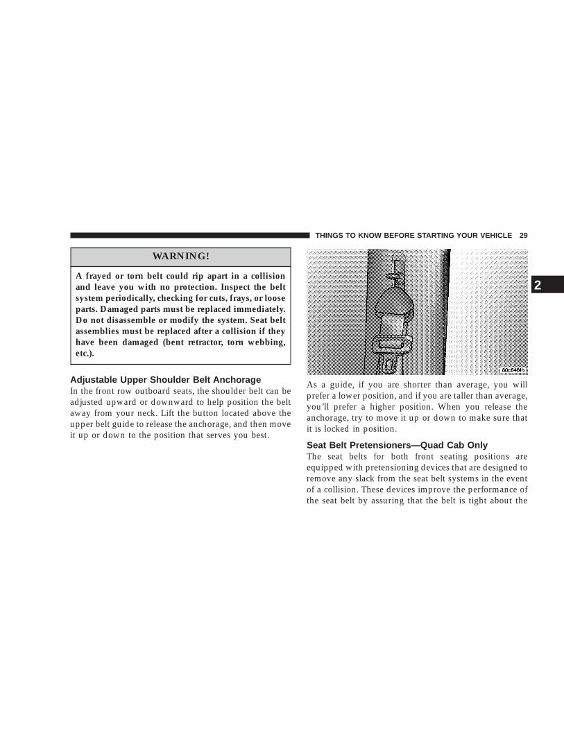
Adjustable Upper Shoulder Belt AnchorageIn the front row outboard seats, the shoulder belt can beadjusted upward or downward to help position the beltaway from your neck. Lift the button located above theupper belt guide to release the anchorage, and then moveit up or down to the position that serves you best.
As a guide, if you are shorter than average, you willprefer a lower position, and if you are taller than average,you’ll prefer a higher position. When you release theanchorage, try to move it up or down to make sure thatit is locked in position.
Seat Belt Pretensioners—Quad Cab OnlyThe seat belts for both front seating positions areequipped with pretensioning devices that are designed toremove any slack from the seat belt systems in the eventof a collision. These devices improve the performance ofthe seat belt by assuring that the belt is tight about the
THINGS TO KNOW BEFORE STARTING YOUR VEHICLE 29
2

occupant early in a collision. Pretensioners work for allsize occupants, including those in child restraints.
NOTE: These devices are not a substitute for properseat belt placement by the occupant. The seat belt stillmust be worn snugly and positioned properly.
The pretensioners are triggered by the airbag controlmodule. Like the airbags, the pretensioners are single useitems. After a collision that is severe enough to deploythe airbags and pretensioners, both must be replaced.
Front Lap BeltsThe center seating positions have a lap belt only. To fastenthe lap belt, slide the latch plate into the buckle until youhear a 9click.9 To lengthen the lap belt, tilt the latch plateand pull. To remove slack, pull the loose end of thewebbing. Wear the lap belt snug against the hips. Sit backand erect in the seat, then adjust the belt as tightly as iscomfortable.
WARNING!
• A lap belt worn too loose or too high is dangerous.
• A belt worn too loose can allow you to slip downand under the belt in a collision.
• A belt that is too loose or too high will apply crashforces to the abdomen, not to the stronger hipbones. In either case, the risk of internal injuriesis greater. Wear a lap belt low and snug.
Seat Belts and Pregnant WomenWe recommend that pregnant women use seat beltsthroughout their pregnancies. Keeping the mother safe isthe best way to keep the baby safe.
Pregnant women should wear the lap part of the beltacross the thighs and as snug against the hips as possible.Keep the belt low so that it does not come across theabdomen. That way the strong bones of the hips will takethe force if there is a collision.
30 THINGS TO KNOW BEFORE STARTING YOUR VEHICLE

Seat Belt ExtenderIf a seat belt is too short, even when fully extended, yourdealer can provide you with a seat belt extender. Thisextender should be used only if the existing belt is notlong enough. When it is not required, remove the ex-tender and store it.
WARNING!
Using a seat belt extender when not needed canincrease the risk of injury in a collision. Only use theseat belt extender when the lap belt is not longenough when it is worn low and snug, and in therecommended seating positions. Remove and storethe extender when not needed.
Driver And Right Front Passenger SupplementalRestraint System—AirbagThis vehicle has front airbags for both the driver andfront passenger as a supplement to the seat belt restraintsystems. The driver’s front airbag is mounted in thecenter of the steering wheel. The passenger’s front airbag
is mounted in the instrument panel, above the glovecompartment. The words SRS AIRBAG are embossed onthe airbag covers.
These airbags are certified to the new Federal regulationsthat allow less forceful deployments.
THINGS TO KNOW BEFORE STARTING YOUR VEHICLE 31
2

WARNING!
Do not put anything on or around the front airbagcovers or attempt to manually open them. You maydamage the airbags and you could be injured be-cause the airbags are not there to protect you. Theseprotective covers for the airbag cushions are de-signed to open only when the airbags are inflating.
Airbags inflate in moderate to high speed impacts. Alongwith the seatbelts, front airbags work with the instrumentpanel knee bolsters to provide improved protection forthe driver and front passenger.
The seat belts are designed to protect you in many typesof collisions. The front airbags deploy in moderate tosevere frontal collisions. But even in collisions where theairbags work, you need the seat belts to keep you in theright position for the airbags to protect you properly.
Here are some simple steps you can follow to minimizethe risk of harm from a deploying airbag.
• Children 12 years and under should ride buckled up ina rear seat, if available.
• Infants in rear facing child restraints must NEVERride in the front seat of a vehicle with a passenger frontairbag unless the airbag is turned off. An airbagdeployment could cause severe injury or death toinfants in that position. See the passenger airbagon/off switch section.
• If your vehicle does not have a rear seat, see thePassenger Airbag On/Off Switch section.
• Children that are not big enough to properly wear thevehicle seat belt (see section on Child Restraints)should be secured in the rear seat in child restraints orbelt-positioning booster seats. Older children who donot use child restraints or belt-positioning boosterseats should ride properly buckled up in the rear seat.Never allow children to slide the shoulder belt behindthem or under their arm.
• All occupants should use their seat belts properly.
32 THINGS TO KNOW BEFORE STARTING YOUR VEHICLE

• The driver and front passenger seats should be movedback as far as practical to allow the airbag room toinflate.
WARNING!
• Relying on the airbags alone could lead to moresevere injuries in a collision. The airbags workwith your seat belt to restrain you properly. Insome collisions the airbags won’t deploy at all.Always wear your seat belts even though youhave airbags.
• Being too close to the steering wheel or instru-ment panel during airbag deployment could causeserious injury. Airbags need room to inflate. Sitback, comfortably extending your arms to reachthe steering wheel or instrument panel.
Airbag System Components
The airbag system consists of the following:
• Airbag Control Module
• AIRBAG Readiness Light
• Driver Airbag
• Passenger Airbag
• Steering Wheel and Column
• Instrument Panel
• Airbag Control Module bullet (with integrated crashsensor)
• Interconnecting Wiring
• Knee Impact Bolsters
• Passenger Side Frontal Airbag ON/OFF Switch
How The Airbag System Works
• The airbag control module determines if a frontalcollision is severe enough to require the airbags toinflate.
• The airbag control module will not detect side, rollover, or rear collisions.
THINGS TO KNOW BEFORE STARTING YOUR VEHICLE 33
2

• The airbag control module also monitors the readinessof the electronic parts of the system whenever theignition switch is in the START or RUN positions.These include all of the items listed above except theknee bolsters, the instrument panel, and the steeringwheel and column If the key is in the 9off9 position, inthe ACC position, or not in the ignition, the airbags arenot on and will not inflate
• The airbag control module also turns on the AIRBAGlight in the instrument panel for 6 to 8 seconds whenthe ignition is first turned on, then turns the light off.If it detects a malfunction in any part of the system, itturns on the light either momentarily or continuously.
WARNING!
Ignoring the AIRBAG light in your instrument panelcould mean you won’t have the airbags to protectyou in a collision. If the light does not come on, stayson after you start the vehicle, or if it comes on as youdrive, have the airbag system checked right away.
• When the airbag control module detects a collisionrequiring the airbags, it signals the inflator units. Alarge quantity of nontoxic gas is generated to inflatethe airbags. The airbag covers separate and fold out ofthe way as the airbags inflate to their full size. Theairbags fully inflate in milliseconds. This is only abouthalf of the time it takes you to blink your eyes. Theairbags then quickly deflate while helping to restrainthe driver and front passenger. The driver’s frontairbag gas is vented through the airbag materialtowards the instrument panel. The passenger’s frontairbag gas is vented through vent holes in the sides ofthe airbag. In this way the airbags do not interfere withyour control of the vehicle.
• The knee impact bolsters help protect the knees andposition you for the best interaction with the frontairbag.
Passenger Airbag On/Off Switch – If EquippedThe passenger front airbag is to be turned off only if thepassenger:
• is an infant (less than 1 year old) who must ride in thefront seat because there is no rear seat, because the rear
34 THINGS TO KNOW BEFORE STARTING YOUR VEHICLE

seat is too small for a rear-facing infant restraint orbecause the infant has a medical condition whichmakes it necessary for the driver to be able to see theinfant,
• is a child, age 1 to 12 who must ride in the front seatbecause there is no rear seat, because there is no rearseat position available, or because the child has amedical condition which makes it necessary for thedriver to be able to see the child,
• has a medical condition which makes passenger airbaginflation (deployment) a greater risk for the passengerthan the risk of hitting the dashboard (instrumentpanel) or windshield in a crash.
WARNING!
Whenever an airbag is turned off, even a lap/shoulder belted passenger may hit their head, neck,or chest on the dashboard (instrument panel) orwindshield in a crash. This may result in seriousinjury or death.
NOTE: The Passenger Airbag On/Off Switch is notavailable in the Quad Cab.
To Shut Off the Passenger Airbag
Place the ignition key in the Passenger Airbag On/OffSwitch, push the key in and turn clockwise, and removethe key from the switch. This will shut off the passengerside airbag. The “Off” light near the switch will illumi-nate when the ignition switch is turned to the ONposition.
THINGS TO KNOW BEFORE STARTING YOUR VEHICLE 35
2

To Turn On the Passenger Airbag
Place the ignition key in the Passenger Airbag On/OffSwitch, push the key in and turn counterclockwise, andremove the key from the switch. This will turn on thepassenger airbag. The “Off” light near the switch will beoff when the ignition switch is turned to the ON position.
If A Deployment OccursThe airbag system is designed to deploy when the air bagcontrol module detects a moderate-to-severe frontal col-lision, and then immediately to deflate.
NOTE: A frontal collision that is not severe enough toneed airbag protection will not activate the system. Thisdoes not mean something is wrong with the airbagsystem.
If you do have a collision which deploys the airbags, anyor all of the following may occur:
• The nylon airbag material may sometimes cause abra-sions and/or skin reddening to the driver and frontpassenger as the airbags deploy and unfold. Theabrasions are similar to friction rope burns or thoseyou might get sliding along a carpet or gymnasium
floor. They are not caused by contact with chemicals.They are not permanent and normally heal quickly.However, if you haven’t healed significantly within afew days, or if you have any blistering, see your doctorimmediately.
• As the airbags deflate you may see some smoke-likeparticles. The particles are a normal by-product of theprocess that generates the nontoxic gas used for airbaginflation. These airborne particles may irritate the skin,eyes, nose, or throat. If you have skin or eye irritation,rinse the area with cool water. For nose or throatirritation, move to fresh air. If the irritation continues,see your doctor. If these particles settle on yourclothing, follow the garment manufacturers instruc-tions for cleaning.
• It is not advisable to drive your vehicle after theairbags have deployed. If you are involved in anothercollision, the airbags will not be in place to protect you.
36 THINGS TO KNOW BEFORE STARTING YOUR VEHICLE

WARNING!
Deployed airbags can’t protect you in another colli-sion. Have the airbags replaced by an authorizeddealer as soon as possible.
Enhanced Accident Response SystemIf the airbags deploy after an impact and the electricalsystem remains functional, vehicles equipped withpower door locks will unlock automatically. In addition,approximately 10 seconds after the vehicle has stoppedmoving, the interior lights will light until the ignitionswitch is turned off.
Maintaining Your Airbag Systems
WARNING!
• Modifications to any part of the airbag systemcould cause it to fail when you need it. You couldbe injured because the airbags are not there toprotect you. Do not modify the components orwiring, including adding any kind of badges orstickers to the steering wheel hub trim cover orthe upper right side of the instrument panel. Donot modify the front bumper, vehicle body struc-ture, or frame.
• You need proper knee impact protection in acollision. Do not mount or locate any aftermarketequipment on or behind the knee bolster.
• It is dangerous to try to repair any part of theairbag system yourself. Be sure to tell anyone whoworks on your vehicle that it has airbags.
THINGS TO KNOW BEFORE STARTING YOUR VEHICLE 37
2

Airbag LightYou will want to have the airbags ready to inflate for yourprotection in an impact. While the airbag system isdesigned to be maintenance free, if any of the followingoccurs, have an authorized dealer service the systempromptly:
• The airbag light does not come on or flickers duringthe 6 to 8 seconds when the ignition switch is firstturned on.
• The light remains on or flickers after the 6 to 8 secondinterval.
• The light flickers or comes on and remains on whiledriving.
NOTE: If the speedometer, tachometer or any enginerelated gauges are not working, the airbag control mod-ule may also be disabled. The airbags may not be readyto inflate for your protection. Promptly check fuse num-bers 18 and 19 in the fuse block. See your dealer if thefuse is good.
Child RestraintEveryone in your vehicle needs to be buckled up all thetime — babies and children, too. Every state in the UnitedStates and all Canadian provinces require that smallchildren ride in proper restraint systems. This is the law,and you can be prosecuted for ignoring it.
Children 12 years and under should ride properly buck-led up in a rear seat, if available. According to crashstatistics, children are safer when properly restrained inthe rear seats rather than in the front.
WARNING!
In a collision, an unrestrained child, even a tinybaby, can become a missile inside the vehicle. Theforce required to hold even an infant on your lap canbecome so great that you could not hold the child, nomatter how strong you are. The child and otherscould be badly injured. Any child riding in yourvehicle should be in a proper restraint for the child’ssize.
38 THINGS TO KNOW BEFORE STARTING YOUR VEHICLE

Infants and Small ChildrenThere are different sizes and types of restraints forchildren from newborn size to the child almost largeenough for the adult seat belt. Use the restraint that iscorrect for your child:
• Safety experts recommend that children riderearward-facing in the vehicle until they are at leastone year old and weigh at least 20 lbs (9 kg). Two typesof child restraints can be used rearward-facing: infantcarriers and 9convertible9 child seats. Both types ofchild restraints are held in the vehicle by the lap/shoulder belt.
• The infant carrier is only used rearward-facing in thevehicle. It is recommended for children who weigh upto about 20 lbs (9 kg). 9Convertible9 child seats can beused either rearward-facing or forward-facing in thevehicle. Convertible child seats often have a higherweight limit in the rearward-facing direction thaninfant carriers do, so they can be used rearward-facingby children who weigh more than 20 lbs (9 kg) but areless than one year old.
• Rearward-facing child seats must NEVER be used inthe front seat of a vehicle with a front passenger airbagunless the airbag is turned off. An airbag deploymentcould cause severe injury or death to infants in thisposition.
• Children who weigh more than 20 lbs. (9 kg) and whoare older than one year can ride forward-facing in thevehicle. Forward-facing child seats and convertiblechild seats used in the forward-facing direction are forchildren who weigh 20 to 40 lbs (9 to 18 kg) and whoare older than one year. These child seats are also heldin the vehicle by the lap/shoulder belt.
• The belt-positioning booster seat is for children weigh-ing more than 40 lbs (18 kg), but who are still too smallto fit the vehicle’s seat belts properly. If the childcannot sit with knees bent over the vehicle’s seatcushion while the child’s back is against the seat back,they should use a belt-positioning-booster seat. Thechild and booster seat are held in the vehicle by thelap/shoulder belt. (Some booster seats are equipped
THINGS TO KNOW BEFORE STARTING YOUR VEHICLE 39
2

with a front shield and are held in the vehicle by thelap portion.) For further information refer towww.seatcheck.org.
WARNING!
• Improper installation can lead to failure of aninfant or child restraint. It could come loose in acollision. The child could be badly injured orkilled. Follow the manufacturers directions ex-actly when installing an infant or child restraint.
• A rearward facing child restraint should only beused in a rear seat, or in the front seat if thepassenger’s front airbag is Off. If the airbag is leftOn, a rearward facing child restraint in the frontseat may be struck by a deploying passengerairbag which may cause severe or fatal injury tothe infant.
Here are some tips for getting the most out of your childrestraint:
• Before buying any restraint system, make sure that ithas a label certifying that it meets all applicable SafetyStandards. We also recommend that you make surethat you can install the child restraint in the vehiclewhere you will use it before you buy it.
• The restraint must be appropriate for your child’sweight and height. Check the label on the restraint forweight and height limits.
• Carefully follow the instructions that come with therestraint. If you install the restraint improperly, it maynot work when you need it.
• The passenger seat belts are equipped with cinchinglatch plates, which are designed to keep the lap portiontight around the child restraint so that it is not neces-sary to use a locking clip. Pulling up on the shoulderportion of the lap/shoulder belt will tighten the belt.The cinching latch plate will keep the belt tight, how-ever, any seat belt system will loosen with time, socheck the belt occasionally and pull it tight if necessary.
40 THINGS TO KNOW BEFORE STARTING YOUR VEHICLE

• In the rear seat, you may have trouble tightening thelap/shoulder belt on the child restraint because thebuckle or latch plate is too close to the belt pathopening on the restraint. Disconnect the latch platefrom the buckle and twist the short buckle-end beltseveral times to shorten it. Insert the latch plate intothe buckle with the release button facing out.
• If the belt still can’t be tightened, or if pulling andpushing on the restraint loosens the belt, disconnectthe latch plate from the buckle, turn the bucklearound, and insert the latch plate into the buckleagain. If you still can’t make the child restraint secure,try a different seating position.
• Buckle the child into the seat according to the childrestraint manufacturers directions.
• When your child restraint is not in use, secure it in thevehicle with the seat belt or remove it from the vehicle.Do not leave it loose in the vehicle. In a sudden stop orcollision, it could strike the occupants or seat backsand cause serious personal injury.
WARNING!
Improper installation can lead to failure of an infantor child restraint. It could come loose in a collision.The child could be badly injured or killed. Followthe manufacturers directions exactly when installingan infant or child restraint.
THINGS TO KNOW BEFORE STARTING YOUR VEHICLE 41
2

Lower Anchors and Tether for CHildren (LATCH)Each vehicle is equipped with the child restraint anchor-age system called LATCH, which stands for LowerAnchors and Tether for CHildren. LATCH child restraintanchorage systems are installed in the Standard Cabpassenger seat position, the Club Cab front passengerand rear outboard right side positions and the Quad Cabrear seat outboard positions and also feature tether strapanchorages, which must be used, located behind theseatback (refer to Child Restraint Tether Anchor later inthis section).
Standard and Club Cab Front Seat
42 THINGS TO KNOW BEFORE STARTING YOUR VEHICLE

Club Cab Rear Right Seat Quad Cab Rear Right Seat
THINGS TO KNOW BEFORE STARTING YOUR VEHICLE 43
2

NOTE: For children riding in the front seat of aStandard Cab model refer to the “Passenger AirbagOn/Off Switch” located in this section.
Child restraint systems having attachments designed toconnect to the lower anchorages are now available. Childrestraints having tether straps and hooks for connectionto the seatback tether anchorage have been available forsome time. In fact, many child restraint manufacturerswill provide add-on tether strap kits for some of theirolder products.
Because the lower anchorages are to be introduced topassenger carrying vehicles over a period of years, childrestraint systems having attachments for those anchor-ages will continue to have features for installation invehicles using the lap or lap/shoulder belt. They will alsohave tether straps, and you are urged to take advantageof all of the available attachments provided with yourchild restraint in any vehicle.
NOTE: If your child restraint seat is not LATCHcompatible, install the restraint using the vehicle seatbelting.
Quad Cab Rear Left Seat
44 THINGS TO KNOW BEFORE STARTING YOUR VEHICLE

Installing the Child Restraint System
WARNING!
Do not install child restraint systems equipped withLATCH attachments in the center position of a QuadCab model rear seat. The LATCH anchorages in thisseat are designed for the two outboard seating posi-tions only. A child may be placed in the rear centerseating position of a Quad Cab model using the seatbelt and child tether anchorage. Failure to follow thismay result in serious or fatal injury.
We urge that you carefully follow the directions of themanufacturer when installing your child restraint. Many,but not all, restraint systems will be equipped withseparate straps on each side, with each having a hook orconnector and a means for adjusting the tension in thestrap. Forward-facing toddler restraints and somerearward-facing infant restraints will also be equippedwith a tether strap, a hook and means for adjusting thetension in the strap.
In general, you will first loosen the adjusters on the lowerstraps and tether straps so that you can more easily attachthe hook or connector to the lower anchorages and tetheranchorages. Then tighten all three straps as you push thechild restraint rearward and downward into the seat.
Not all child restraint systems will be installed as wehave described here. Again, carefully follow the instruc-tions that come with the child restraint system.
WARNING!
Improper installation of a child restraint to theLATCH anchorages can lead to failure of an infant orchild restraint. The child could be badly injured orkilled. Follow the manufacturers directions exactlywhen installing an infant or child restraint.
THINGS TO KNOW BEFORE STARTING YOUR VEHICLE 45
2

Child Restraint Tether AnchorRegular Cab models have two tether anchorages, onebehind each passenger seating position (front center andright seat positions). Club Cab and Quad Cab modelshave three anchorages, one behind each of the rear seatpositions (rear left, center, and right seat positions).
WARNING!
With a child restraint installed in the rear driver orpassenger side locations, use care when adjustingthe front seat(s) rearward, to avoid the front seatback coming in contact with the belted child directlybehind the seat. The child could be injured.
WARNING!
Improper installation can lead to failure of an infantor child restraint. It could come loose in a collision.The child could be seriously injured or killed. Makesure the child restraint tether strap is always routedthrough the proper anchor strap inner loop.
Tether Straps at the Front Passenger’s Seat (RegularCab With All Seats)
1. Route the child restraint tether strap up and over thepassenger seat back.
2. Thread the tether strap through the anchor strap innerloop (loop with metal ring), located directly behind thepassenger’s seat.
3. Route the tether strap across to the anchor strapinstalled in the center, and attach the tether strap hook tothe anchor strap metal ring.
46 THINGS TO KNOW BEFORE STARTING YOUR VEHICLE

4. Remove the slack in the tether strap so that bothanchor straps are pulled tight.
Tether Straps at the Front Center Seat (Regular CabWith Any Bench Seat)
1. Route the child restraint tether strap up and over thecenter seat back.
2. Thread the tether strap through the anchor strap innerloop (loop with metal ring), located directly behind thecenter seat.
3. Route the tether strap across to the anchor strapinstalled directly behind the passenger’s seat location,and attach the tether strap hook to the anchor strap metalring.
Regular Cab With All Seats
THINGS TO KNOW BEFORE STARTING YOUR VEHICLE 47
2

4. Remove the slack in the tether strap so that bothanchor straps are pulled tight.
Tether Strap at the Front Passenger Seat (Club Cab)
1. Route the child restraint tether strap up and over thefront passenger seat back.
2. Connect the tether strap to the lower anchorage.
3. Remove the slack in the tether strap so that it is pulledtight.
Regular Cab With Any Bench Seat
Club Cab Front Passenger Seat
48 THINGS TO KNOW BEFORE STARTING YOUR VEHICLE
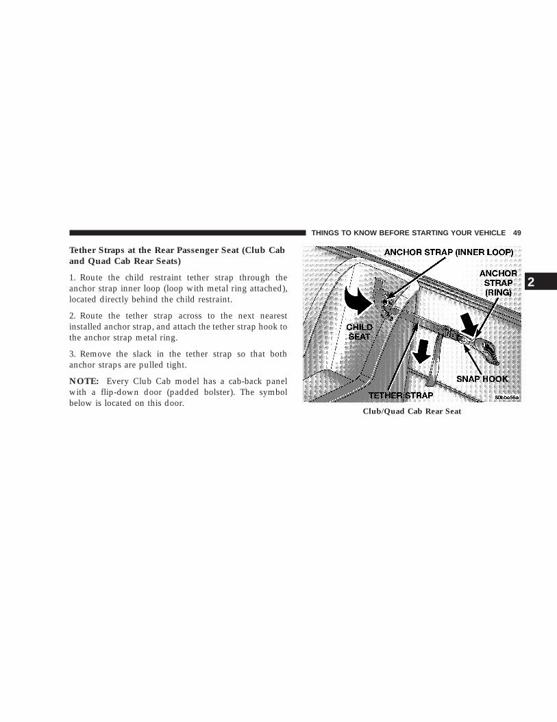
Tether Straps at the Rear Passenger Seat (Club Caband Quad Cab Rear Seats)
1. Route the child restraint tether strap through theanchor strap inner loop (loop with metal ring attached),located directly behind the child restraint.
2. Route the tether strap across to the next nearestinstalled anchor strap, and attach the tether strap hook tothe anchor strap metal ring.
3. Remove the slack in the tether strap so that bothanchor straps are pulled tight.
NOTE: Every Club Cab model has a cab-back panelwith a flip-down door (padded bolster). The symbolbelow is located on this door.
Club/Quad Cab Rear Seat
THINGS TO KNOW BEFORE STARTING YOUR VEHICLE 49
2
Multiple Child Restraint Installation Sequence
1. Thread the child restraint tether strap hook throughthe inner loop, located directly behind the child restraint.
2. After following step 1 for either of the two outer seats,route the tether strap hook to the metal ring on the innerloop behind the center seat and attach the hook to themetal ring.
3. After following step 1 for the center child restraint,route the tether strap hook to the metal ring on the innerloop, located behind the passenger’s seat. Attach thetether strap hook to the metal ring
NOTE: Two Anchors must be used for either of thethree seating positions.
50 THINGS TO KNOW BEFORE STARTING YOUR VEHICLE

Multiple Child Restraint
THINGS TO KNOW BEFORE STARTING YOUR VEHICLE 51
2

WARNING!
An incorrectly anchored tether strap could lead toseat failure and injury to the child. In a collision, theseat could come loose and allow the child to crashinto the inside of the vehicle or other passengers, oreven be thrown from the vehicle. Use only theanchor positions directly behind the child restraintto secure a child restraint top tether strap. See yourdealer for help if necessary.
Children Too Large for Booster SeatsChildren who are large enough to wear the shoulder beltcomfortably, and whose legs are long enough to bendover the front of the seat when their back is against theseat back should use the lap/shoulder belt in a rear seat.
• Make sure that the child is upright in the seat.
• The lap portion should be low on the hips and as snugas possible.
• Check belt fit periodically. A child’s squirming orslouching can move the belt out of position.
If the shoulder belt contacts the face or neck, move thechild closer to the center of the vehicle. If this doesn’thelp, move the child to the center rear seating positionand use the lap belt. Never allow a child to put theshoulder belt under an arm or behind their back.
ENGINE BREAK-IN RECOMMENDATIONSA long break-in period is not required for the engine inyour new vehicle. Drive moderately during the first 300miles (500 km). After the initial 60 miles (100 km), speedsup to 50 or 55 mph (80 or 90 km/h) are desirable. Whilecruising, brief full-throttle acceleration, within the limitsof local traffic laws, contributes to a good break-in.
Avoid wide open throttle acceleration in low gear.
The engine oil installed in the engine at the factory is ahigh-quality, energy-conserving type lubricant. Oilchanges should be consistent with anticipated climateconditions under which vehicle operations will occur.The recommended viscosity and quality grades areshown in Section 7.
NON-DETERGENT OR STRAIGHT MINERAL OILSMUST NEVER BE USED.
52 THINGS TO KNOW BEFORE STARTING YOUR VEHICLE

A new engine may consume some oil during its first fewthousand miles of operation. This is a normal part of thebreak-in and is not an indication of difficulty.
SAFETY TIPS
Exhaust System
WARNING!
Exhaust gases contain carbon monoxide, an ex-tremely toxic gas that by itself is colorless andodorless. To avoid inhaling these gases, the follow-ing precautions should be observed:
• Do not run the engine in a closed garage or in confinedareas any longer than needed to move your vehicle inor out of the area.
• It may be necessary to sit in a parked vehicle with theengine running for more than a short period. If so,adjust your climate control system to force outside airinto the vehicle. Set the blower at high speed and thecontrols in any position except OFF or RECIRC.
• The best protection against carbon monoxide entryinto the vehicle body is a properly maintained engineexhaust system.
Be aware of changes in the sound of the exhaust system;exhaust fumes detected inside the vehicle; or damage tothe underside or rear of the vehicle. Have a competentmechanic inspect the complete exhaust system and adja-cent body areas for broken, damaged, deteriorated ormispositioned parts. Open seams or loose connectionscould permit exhaust fumes to seep into the passengercompartment. In addition, inspect the exhaust systemeach time the vehicle is raised for lubrication or oilchange. Replace or adjust as required.
THINGS TO KNOW BEFORE STARTING YOUR VEHICLE 53
2

Safety Checks You Should Make Inside TheVehicle
Seat BeltsInspect the belt system periodically, checking for cuts,frays and loose parts. Damaged parts must be replacedimmediately. Do not disassemble or modify the system.
Seat belt assemblies must be replaced after an accident ifthey have been damaged (bent retractor, torn webbing,etc.). If there is any question regarding belt or retractorcondition, replace the belt.
DefrostersCheck operation by selecting the defrost mode and placethe blower control on high speed. You can feel the airdirected against the windshield.
Safety Checks You Should Make Outside TheVehicle:
TiresExamine tires for tread wear or uneven wear patterns.Check for stones, nails, glass or other objects lodged inthe tread.
Inspect for tread cuts or sidewall cracks. Check wheelnuts for tightness and tires for proper pressure.
LightsHave someone observe the operation of exterior lights asyou turn them on. Check turn signal and high beamindicator lights on the instrument panel.
Door LatchesCheck for positive closing, latching and locking.
Fluid LeaksCheck the area under vehicle after overnight parking forfuel, water, oil, or other fluid leaks. Also, if gasolinefumes are detected, the cause should be located andcorrected.
54 THINGS TO KNOW BEFORE STARTING YOUR VEHICLE

UNDERSTANDING THE FEATURES OF YOUR VEHICLE
CONTENTS
m Mirrors . . . . . . . . . . . . . . . . . . . . . . . . . . . . . .58
▫ Inside Day/Night Mirror . . . . . . . . . . . . . . . . .58
▫ Automatic Dimming Mirror— If Equipped . . . .59
▫ Outside Mirrors . . . . . . . . . . . . . . . . . . . . . . .59
▫ Exterior Mirrors Folding Feature . . . . . . . . . . .59
▫ Electric Remote-Control Mirrors . . . . . . . . . . . .60
▫ Heated Mirrors — If Equipped . . . . . . . . . . . . .61
m Seats . . . . . . . . . . . . . . . . . . . . . . . . . . . . . . . .61
▫ Seat Adjustment . . . . . . . . . . . . . . . . . . . . . . .61
▫ Reclining Seats . . . . . . . . . . . . . . . . . . . . . . . .62
▫ 6 - Way Power Seat Adjuster — Driver’s SideOnly . . . . . . . . . . . . . . . . . . . . . . . . . . . . . . .63
▫ Lumbar Support Adjustment — Power SeatsOnly . . . . . . . . . . . . . . . . . . . . . . . . . . . . . . .63
▫ Seatback Releases — Bench Seat . . . . . . . . . . . .63
▫ Seatback Releases—Bucket And Split Bench . . . .64
▫ Club Cab Easy Entry System . . . . . . . . . . . . . .64
▫ Club Cab/Quad Cab Rear Seat . . . . . . . . . . . . .65
m To Open And Close The Hood . . . . . . . . . . . . .66
m Lights . . . . . . . . . . . . . . . . . . . . . . . . . . . . . . .67
▫ Interior Lights . . . . . . . . . . . . . . . . . . . . . . . .67
▫ Battery Saver . . . . . . . . . . . . . . . . . . . . . . . . .68
▫ Headlamp Delay . . . . . . . . . . . . . . . . . . . . . . .68
▫ Headlights, Parking Lights, Panel Lights . . . . . .68
3

▫ Daytime Running Lights (Canada Only) . . . . . .69
▫ Lights-On Reminder . . . . . . . . . . . . . . . . . . . .69
▫ Fog Lights — If Equipped . . . . . . . . . . . . . . . .69
▫ Cargo Light — If Equipped . . . . . . . . . . . . . . .70
m Multifunction Control Lever . . . . . . . . . . . . . . .70
▫ Turn Signals . . . . . . . . . . . . . . . . . . . . . . . . . .70
▫ Passing Light . . . . . . . . . . . . . . . . . . . . . . . . .70
▫ High Beam / Low Beam Select Switch . . . . . . .71
▫ Windshield Wipers . . . . . . . . . . . . . . . . . . . . .71
▫ Windshield Washers . . . . . . . . . . . . . . . . . . . .72
m Tilt Steering Column — If Equipped . . . . . . . . .73
m Electronic Speed Control — If Equipped . . . . . .74
▫ To Activate . . . . . . . . . . . . . . . . . . . . . . . . . . .74
▫ To Set At A Desired Speed . . . . . . . . . . . . . . . .74
▫ To Deactivate . . . . . . . . . . . . . . . . . . . . . . . . .74
▫ To Resume Speed . . . . . . . . . . . . . . . . . . . . . .75
▫ To Vary The Speed Setting . . . . . . . . . . . . . . . .75
▫ To Accelerate For Passing . . . . . . . . . . . . . . . .75
m Overhead Console . . . . . . . . . . . . . . . . . . . . . .76
▫ Courtesy/Reading Lights . . . . . . . . . . . . . . . . .76
m Compass/Temperature Mini-Trip Computer . . .77
▫ US/M Button . . . . . . . . . . . . . . . . . . . . . . . . .77
▫ Reset Button . . . . . . . . . . . . . . . . . . . . . . . . . .77
▫ Global Reset . . . . . . . . . . . . . . . . . . . . . . . . . .77
▫ Step Button . . . . . . . . . . . . . . . . . . . . . . . . . .78
▫ Average Fuel Economy (AVG ECO) . . . . . . . . .78
▫ Distance To Empty (DTE) . . . . . . . . . . . . . . . .78
▫ Trip Odometer (ODO) . . . . . . . . . . . . . . . . . . .78
▫ Elapsed Time (ET) . . . . . . . . . . . . . . . . . . . . . .78
▫ C/T Button . . . . . . . . . . . . . . . . . . . . . . . . . .79
▫ Compass/Temperature Display . . . . . . . . . . . .79
▫ Automatic Compass Calibration . . . . . . . . . . . .79
56 UNDERSTANDING THE FEATURES OF YOUR VEHICLE

▫ Manual Compass Calibration . . . . . . . . . . . . . .80
▫ Outside Temperature . . . . . . . . . . . . . . . . . . . .81
m Garage Door Opener . . . . . . . . . . . . . . . . . . . .81
▫ Programming Homelink . . . . . . . . . . . . . . . . .82
▫ Canadian Programming/Gate Programming . . .84
▫ Using Homelink . . . . . . . . . . . . . . . . . . . . . . .85
▫ Erasing Homelink Buttons . . . . . . . . . . . . . . . .85
▫ Reprogramming a Single Homelink Button . . . .85
▫ Security . . . . . . . . . . . . . . . . . . . . . . . . . . . . .85
m Electrical Power Outlets — If Equipped . . . . . .86
▫ Electrical Outlet Use With Engine Off . . . . . . . .87
m Floor Console — If Equipped . . . . . . . . . . . . . .88
▫ Floor Console Features . . . . . . . . . . . . . . . . . .88
m Center Storage Compartment — If Equipped . . .89
m Cup Holders . . . . . . . . . . . . . . . . . . . . . . . . . .89
m Tailgate . . . . . . . . . . . . . . . . . . . . . . . . . . . . . .90
m Slide-In Campers . . . . . . . . . . . . . . . . . . . . . . .90
▫ Camper Applications . . . . . . . . . . . . . . . . . . . .90
▫ General Information . . . . . . . . . . . . . . . . . . . .91
▫ Carbon Monoxide Warning Vehicles EquippedWith A Cap Or Slide-In Campers . . . . . . . . . . .91
UNDERSTANDING THE FEATURES OF YOUR VEHICLE 57
3

MIRRORS
Inside Day/Night MirrorThe mirror should be adjusted to center on the viewthrough the rear window. A two-point pivot systemallows for horizontal and vertical adjustment of themirror.
Annoying headlight glare can be reduced by moving thesmall control under the mirror to the night position(toward rear of truck). The mirror should be adjustedwhile set in the day position (toward windshield).
58 UNDERSTANDING THE FEATURES OF YOUR VEHICLE

Automatic Dimming Mirror— If EquippedThis mirror will automatically adjust for annoying head-light glare from vehicles behind you. You can turn thefeature on or off by pressing the button at the base of themirror. A light in the button will indicate when thedimming feature is activated.
CAUTION!
To avoid damage to the mirror during cleaning,never spray any cleaning solution directly onto themirror. Apply the solution onto a clean cloth andwipe the mirror clean.
Outside MirrorsTo receive maximum benefit, adjust the outside mirror(s)to center on the adjacent lane of traffic with a slightoverlap of the view obtained on the inside mirror.
Exterior Mirrors Folding FeatureFolding exterior mirrors are hinged and may be movedeither forward or rearward to resist damage. The hingeshave three detent positions; full forward, full rearward,and normal.
UNDERSTANDING THE FEATURES OF YOUR VEHICLE 59
3
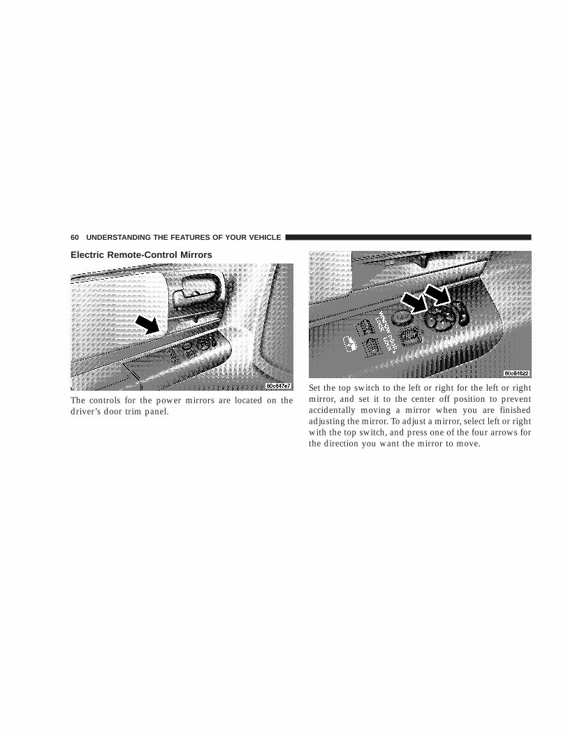
Electric Remote-Control Mirrors
The controls for the power mirrors are located on thedriver’s door trim panel.
Set the top switch to the left or right for the left or rightmirror, and set it to the center off position to preventaccidentally moving a mirror when you are finishedadjusting the mirror. To adjust a mirror, select left or rightwith the top switch, and press one of the four arrows forthe direction you want the mirror to move.
60 UNDERSTANDING THE FEATURES OF YOUR VEHICLE

WARNING!
Vehicles and other objects seen in the right sideconvex mirror will look smaller and farther awaythan they really are. Relying too much on your rightside mirror could cause you to collide with anothervehicle or other object. Use your inside mirror whenjudging the size or distance of a vehicle seen in theright side mirror.
Heated Mirrors — If EquippedHeated mirrors are automatically activated when youdepress the rear window defroster switch located on theinstrument panel. The light will illuminate to indicatethat the heating elements are ON. Turning OFF theignition will deactivate the heated mirrors.
SEATS
Seat AdjustmentThe adjusting lever is at the front of the seat, near thefloor. Lift the lever and move the seat to the desiredposition.
Using body pressure, move forward and rearward on theseat to be sure the seat adjusters have latched.
UNDERSTANDING THE FEATURES OF YOUR VEHICLE 61
3

WARNING!
Adjusting a seat while the vehicle is moving isdangerous. The sudden movement of the seat couldcause you to lose control. The seat belt might not beproperly adjusted and you could be injured. Adjustany seat only while the vehicle is parked.
Reclining SeatsBoth the bucket seats and the split-bench seats areequipped with recliners. The reclining mechanism isoperated by a control located on the outboard side of theseat. To recline, lean forward slightly before lifting thelever, then push back to the desired angle and release thelever. Lean forward and lift the lever to return theseatback to its normal position.
WARNING!
Do not ride with the seatback reclined so that theshoulder belt is no longer resting against your chest.In a collision you could slide under the seat belt andbe seriously or even fatally injured. Use the reclineronly when the vehicle is parked.
62 UNDERSTANDING THE FEATURES OF YOUR VEHICLE

6 - Way Power Seat Adjuster — Driver’s SideOnlyThe 6-way power seat adjuster switch is on the outboardside of the driver’s seat. Use this switch to move the seatup or down, forward or rearward, recline or tilt.
Lumbar Support Adjustment — Power Seats OnlyVehicles equipped with the power bucket seat or the40/20/40 split bench power are equipped with an adjust-able lumbar support on the driver’s seat. Rotating thelever on the left side of the driver’s seatback increases ordecreases the lumbar support.
Seatback Releases — Bench SeatThe seatback is equipped with inertia latching mecha-nisms that automatically lock and prevent the seatbackfrom folding forward during periods of high decelera-tion, such as hard braking.
This type of latch mechanism eliminates the need toactuate a release lever to fold the seat forward. In somesituations, such as when parked on a steep hill, the inertialatch may lock and manual release of the lock will benecessary.
UNDERSTANDING THE FEATURES OF YOUR VEHICLE 63
3

Seatback Releases—Bucket And Split BenchBoth seats have a position latch release. To release theseatback if you are on the outside of the vehicle, lift up onthe recliner lever located on the outboard side of the seat.From the rear seat, lift the lever located on the rear of theseatback.
Club Cab Easy Entry System
To allow easier access to the rear seat, the front passengerseat will move to its full forward position when theseatback is folded down. To fold the seatback forward ifyou are on the outside of the vehicle, lift up on the
recliner lever located on the outboard side of the seat.From the rear seat, pull the cloth pull-tab located on therear or the seat cushion rearward until the latch releases,and then push the seat forward. The seat will lock inplace when the back is returned to an upright positionand will need to be reset. However, the seat may be slidrearward before returning the seatback to the uprightposition to minimize the amount of readjustment re-quired.
NOTE: Power seats are available with the Club or QuadCab models only.
CAUTION!
When operating the folding front seat, use care inrepositioning seat to its normal position. This willprevent shoulder belt harness from being caughtbehind seat or tangled in the seatback latchingmechanism.
64 UNDERSTANDING THE FEATURES OF YOUR VEHICLE

WARNING!
It is extremely dangerous to ride in a cargo area,inside or outside of a vehicle. In a collision, peopleriding in these areas are more likely to be seriouslyinjured or killed.
Do not allow people to ride in any area of yourvehicle that is not equipped with seats and seat belts.
Be sure everyone in your vehicle is in a seat andusing a seat belt properly.
Club Cab/Quad Cab Rear SeatMore cargo space is available by lifting up on the rearseat cushion.
The Club Cab/Quad Cab rear seat is a 60/40 splitcushion and full back. Either cushion can be raisedindependently.
UNDERSTANDING THE FEATURES OF YOUR VEHICLE 65
3

TO OPEN AND CLOSE THE HOODTo open the hood, two latches must be released. First pullthe hood release lever located under the left side of theinstrument panel.
Second, locate the hood safety latch lever between thefront grille openings to the left of center. Push this leverto the right to release the hood.
To prevent possible damage, do not slam the hood toclose it. Use a firm downward push at the center of thehood to ensure that both latches engage. Never driveyour vehicle unless the hood is fully closed, with bothlatches engaged.
66 UNDERSTANDING THE FEATURES OF YOUR VEHICLE

WARNING!
If the hood is not fully latched, it could fly up whenthe vehicle is moving and block your forward vision.Be sure all hood latches are fully latched beforedriving.
LIGHTS
Interior Lights
Courtesy and dome lights are turned on when the frontdoors are opened, when the dimmer control (rotatingwheel on the right side of the switch) is rotated to thesecond upward detent position, or if equipped, when theUNLOCK button is pressed on the key fob. Rotating thedimmer control to the optional fully upward position willturn on the cargo light located on the back of the cab.When a door is open and the interior lights are on,rotating the dimmer control all the way down to the OFFdetent will cause all the interior lights to go out. This is
UNDERSTANDING THE FEATURES OF YOUR VEHICLE 67
3

also known as the 9Party9 mode because it allows thedoors to stay open for extended periods of time withoutdischarging the vehicle’s battery.
The brightness of the instrument panel lighting can beregulated by rotating the dimmer control up (brighter) ordown (dimmer). When the headlights are ON you cansupplement the brightness of the odometer, trip odom-eter, radio and overhead console by rotating the controlup until you hear a click. This feature is termed the“Parade” mode and is useful when headlights are re-quired during the day.
Club Cab/Quad Cab models may have an optionalswitched dome lamp that may be operated by pressingthe lens.
Battery SaverTo protect the life of your vehicle’s battery, Load Shed-ding is provided for both the interior and exterior lights.
If the ignition is off and any door is left ajar for 15minutes or the dimmer control is rotated upwards for 15minutes, the interior lights will automatically turn off.
If the headlamps remain on while the ignition is cycledoff, the exterior lights will automatically turn off after 5minutes. If the headlamps are turned on and left on for 15minutes while the ignition is off, the exterior lights willautomatically turn off.
NOTE: Battery Saver mode is cancelled if the ignition isON.
Headlamp DelayTo aid in your exit, your vehicle is equipped with aheadlamp delay that will leave the headlamps on for 60seconds. This delay is initiated when the ignition isturned OFF while the headlamp switch is on, and thenthe headlamp switch is cycled off. The headlamps willremain on for 60 seconds. Headlamp delay can becancelled by either turning the headlamp switch ON thenOFF or by turning the ignition ON.
Headlights, Parking Lights, Panel LightsWhen the headlight switch is rotated to the firstposition, the parking lights, taillights, side markerlights, license plate light and instrument panel
lights are all turned on. The headlights will turn ONwhen the switch is rotated to the second position.
68 UNDERSTANDING THE FEATURES OF YOUR VEHICLE

Your vehicle is equipped with plastic headlight lensesthat are lighter and less susceptible to stone breakagethan glass headlights.
Plastic is not as scratch resistant as glass and thereforedifferent lens cleaning procedures must be followed.
To minimize the possibility of scratching the lenses andreducing light output, avoid wiping with a dry cloth. Toremove road dirt, wash with a mild soap solution fol-lowed by rinsing.
Do not use abrasive cleaning components, solvents, steelwool or other abrasive materials to clean the lenses.
Daytime Running Lights (Canada Only)The headlights on your vehicle will illuminate when theengine is started. This provides a constant 9Lights ON9condition until the ignition is turned OFF. The lightsilluminate at less than 50% of normal intensity. If theparking brake is applied the Daytime Running Lightswill turn off.
Lights-on ReminderIf the headlights, parking lights, courtesy lights or cargolights are left on, after the ignition is turned off, a chimewill sound when the driver’s door is opened.
Fog Lights — If EquippedThe foglights are turned ON by placing the headlightrotary control in the parking light or headlight positionand pulling out the headlight rotary control. The foglights will operate only when the parking lights are ONor when the vehicle headlights are ON low beam. Anindicator light located left of the switch will illuminatewhen the fog lights are on. The fog lights will turn off
UNDERSTANDING THE FEATURES OF YOUR VEHICLE 69
3

when the switch is pressed in, when the headlight switchis rotated to the OFF position or the high beam isselected.
CARGO Light — If EquippedThe cargo lights are turned on by rotating the dimmercontrol to the optional fully upward position. The interiorlights will also turn on when the cargo lights are on. Thecargo lights will also turn on for 30 seconds when a keyfob Unlock is pressed, as part of the illuminated entryfeature.
MULTIFUNCTION CONTROL LEVERThe multifunction control lever is located on the left sideof the steering column.
Turn SignalsMove the lever up or down to signal a right-hand orleft-hand turn.
The arrow on either side of the instrument cluster flashesto indicate the direction of the turn, and proper operationof the front and rear turn signal lights. If either indicatorflashes at a faster rate, check for a defective outside light
bulb. If an indicator fails to light when the lever ismoved, it would suggest that the fuse or indicator bulb isdefective.
You can signal a lane change by moving the leverpartially up or down.
Passing LightYou can signal another vehicle with your headlights bypartially pulling the multifunction lever toward the steer-ing wheel. This will cause the high beam headlights toturn on until the lever is released.
70 UNDERSTANDING THE FEATURES OF YOUR VEHICLE

High Beam / Low Beam Select SwitchPull the multifunction control lever fully toward thesteering wheel to switch the headlights from HIGH orLOW beam.
Windshield WipersThe wipers and washers are operated by a switchin the multifunction control lever. Turn the end ofthe handle to select the desired wiper speed.
NOTE: In cold weather, always turn off the wiperswitch and allow the wipers to return to the park positionbefore turning off the engine. If the wiper switch is left onand the wipers freeze to the windshield, damage to thewiper motor may occur when the vehicle is restarted.
Intermittent Wiper System
UNDERSTANDING THE FEATURES OF YOUR VEHICLE 71
3

The intermittent feature of this system was designed foruse when weather conditions make a single wiping cycle,with a variable pause between cycles, desirable. Formaximum delay between cycles, rotate the control knobinto the upper end of the delay range.
The delay interval decreases as you rotate the knob untilit enters the LO continual speed position. The delay canbe regulated from a maximum of about 15 secondsbetween cycles, to a cycle every 2 seconds.
WARNING!
Sudden loss of visibility through the windshieldcould lead to an accident. You might not see othervehicles or other obstacles. To avoid sudden icing ofthe windshield during freezing weather, warm thewindshield with defroster before and during wind-shield washer use.
Speed-Sensitive Intermittent Wipe — If EquippedFor vehicles equipped with Speed-Sensitive IntermittentWipe, if the vehicle is moving at a speed of less than 10mph (16 km/h), the delay time between wipes will bedoubled, resulting in a longer time between wipes (1–36seconds).
Windshield WashersTo use the washer, push in on the knob on the end of themultifunction control lever and hold while spray isdesired. If the knob is depressed while in the delay range,the wiper will operate for several seconds after the knobis released. It will then resume the intermittent interval
72 UNDERSTANDING THE FEATURES OF YOUR VEHICLE

previously selected. If the knob is pushed while in theOFF position, the wiper will wipe approximately threewipes, after the wash knob is released.
To prevent freeze-up of your windshield washer systemin cold weather, select a solution or mixture that meets orexceeds the temperature range of your climate. Thisrating information can be found on most washer fluidcontainers.
TILT STEERING COLUMN — IF EQUIPPEDTo tilt the column, push down on the lever below the turnsignal control and move the wheel up or down, asdesired. Push the level back up to lock the column firmlyin place.
WARNING!
Tilting the steering column while the vehicle ismoving is dangerous. Without a stable steering col-umn, you could lose control of the vehicle and havean accident. Adjust the column only while the ve-hicle is stopped. Be sure it is locked before driving.
UNDERSTANDING THE FEATURES OF YOUR VEHICLE 73
3

ELECTRONIC SPEED CONTROL — IF EQUIPPEDWhen engaged, this device takes over accelerator opera-tion at speeds greater than 35 mph (56 km/h). Thecontrols are mounted on the steering wheel.
To ActivatePush the ON/OFF button to the ON position. An indi-cator light in the instrument cluster illuminates when thesystem is on.
To Set At A Desired SpeedWhen the vehicle has reached the desired speed, pressand release the SET button. Release the accelerator andthe vehicle will operate at the selected speed.
To DeactivateA soft tap on the brake pedal, normal braking, clutchpressure while slowing the vehicle, or pressing the CAN-CEL button will deactivate speed control without erasingthe memory. Pushing the ON/OFF button to the OFFposition or turning off the ignition erases the memory.
WARNING!
Leaving the Speed Control ON when not in use isdangerous. You could accidentally set the system tocause it to go faster than you want. You could losecontrol and have an accident. Always leave thesystem OFF when you aren’t using it.
74 UNDERSTANDING THE FEATURES OF YOUR VEHICLE

To Resume SpeedTo resume a previously set speed, push and release theRESUME button. Resume can be used at any speed above50 km/h (30 mph).
To Vary The Speed SettingWhen the speed control is on, speed can be increased bypressing and holding the ACCEL button. When thebutton is released, a new set speed will be established.
Tapping the ACCEL button once will result in a 2 mph(3.2 km/h) speed increase. Each time the button istapped, speed increases so that tapping the button threetimes will increase speed by 6 mph (9.6 km/h), etc.
Tapping the COAST button once will result in a 1 mph(1.6 km/h) speed decrease. Each time the button istapped, speed will decrease. For example, tapping thebutton 3 times will decrease the speed by 3 mph (4.8km/h), etc.
To decrease speed while the speed control is on, pressand hold the COAST button. Release the button when thedesired speed is reached, and the new speed will be set.
To Accelerate For PassingDepress the accelerator as you would normally. When thepedal is released, the vehicle will return to the set speed.
NOTE: When driving uphill, at elevations above 2,000feet (610 Meters), or when the vehicle is heavily loaded(especially when towing) the vehicle may slow below theSET speed. If the vehicle speed drops below 30 mph (48km/h), the speed control will automatically disengage. Ifthis happens, you can push down on the acceleratorpedal to maintain the desired speed.
Vehicles equipped with a 5–speed manual transmissionshould be operated in 4th gear under the above condi-tions.
Vehicles equipped with a 4–speed automatic transmis-sion may exhibit several 4-3 downshifts under the aboveconditions. To reduce the frequency of the downshiftsand to improve vehicle performance, it is advisable tolock out overdrive by pressing the O/D OFF buttonlocated at the end of the gear shifter.
UNDERSTANDING THE FEATURES OF YOUR VEHICLE 75
3

WARNING!
Speed Control can be dangerous where the systemcan’t maintain a constant speed. Your vehicle couldgo too fast for the conditions, and you could losecontrol. An accident could be the result. Don’t useSpeed Control in heavy traffic or on roads that arewinding, icy, snow-covered, or slippery.
OVERHEAD CONSOLEThe overhead console has the following features:
• Courtesy Lights
• Garage Door Opener — If Equipped
• Mini-Trip Computer — If Equipped
Courtesy/Reading LightsNear the front of the console are two courtesy/readinglights.
Both lights illuminate as courtesy lights when a door isopened, when the dimmer control is rotated to thecourtesy light position (fully upward position), or whenthe UNLOCK button is pressed on the Remote KeylessEntry transmitter, if so equipped. These lights are alsooperated individually as reading lights by pressing therecessed area of the corresponding lens.
NOTE: The courtesy/reading lights will remain onuntil the switch is pressed a second time, so be sure theyhave been turned off before leaving the vehicle.
76 UNDERSTANDING THE FEATURES OF YOUR VEHICLE
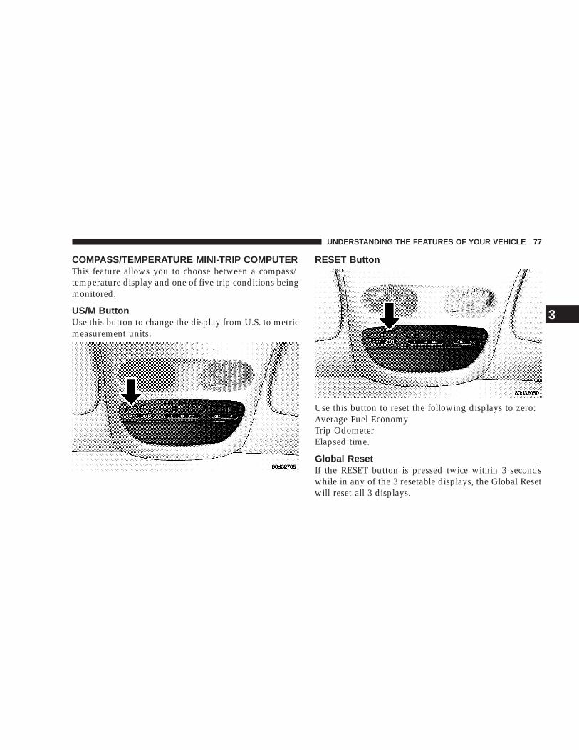
COMPASS/TEMPERATURE MINI-TRIP COMPUTERThis feature allows you to choose between a compass/temperature display and one of five trip conditions beingmonitored.
US/M ButtonUse this button to change the display from U.S. to metricmeasurement units.
RESET Button
Use this button to reset the following displays to zero:Average Fuel EconomyTrip OdometerElapsed time.
Global ResetIf the RESET button is pressed twice within 3 secondswhile in any of the 3 resetable displays, the Global Resetwill reset all 3 displays.
UNDERSTANDING THE FEATURES OF YOUR VEHICLE 77
3

Step Button
Use this button to choose or cycle through the four tripconditions.
Average Fuel Economy (AVG ECO)This display shows the average fuel economy since thelast reset.
Distance To Empty (DTE)This display shows the estimated distance that can betraveled with the fuel remaining in the tank. The distanceis calculated by multiplying the amount of fuel remain-ing by the projected fuel economy. The distance predictedwill change every few seconds to a higher or lowernumber as these factors change. The DTE will read zerowhen the fuel gauge reads “E.”
This display cannot be reset.
Trip Odometer (ODO)This display shows the distance traveled since the lastreset.
Elapsed Time (ET)This display shows the accumulated ignition ON timesince the last reset.
78 UNDERSTANDING THE FEATURES OF YOUR VEHICLE

C/T Button
Use this button to select a readout of the outside tem-perature and one of eight compass headings that indicatethe direction in which the vehicle is facing.
Compass/Temperature DisplayThis display provides the outside temperature and one ofeight compass readings to indicate the direction thevehicle is facing.
WARNING!
Even if the display still reads a few degrees above32°F ( 0°C), the road surface may be icy, particularlyin woods or on bridges. Drive carefully under suchconditions to prevent an accident and possible per-sonal injury or property damage.
Automatic Compass CalibrationThe self calibrating feature of the compass eliminates theneed to calibrate the compass for normal conditions.During a short initial period, the compass may appearerratic and the CAL symbol will appear on the display.The CAL symbol may also appear after the vehicle issubjected to a high level of magnetism. While completingthree 360° turns at about 5 mph (8 km/h) in an area freefrom large metal or metallic objects, the CAL symbol willturn off and the compass will function normally.
UNDERSTANDING THE FEATURES OF YOUR VEHICLE 79
3

Manual Compass CalibrationIf the compass appears erratic and the CAL light does notappear, you must calibrate the compass. Find an openarea away from large metal objects. With the ignition ONand the compass/temperature displayed, press and holdthe RESET button until the CAL symbol appears (about10 seconds). Drive slowly, about 5 mph (8 km/h), in 3complete 360° circles. The CAL light will turn off and thecompass will be calibrated.
Variance is the difference between magnetic North andgeographic North. For proper compass function, thecorrect variance zone must be set. Refer to the variancemap for the correct variance zone. To check the variancezone, the ignition must be on and the compass/temperature displayed. Press and hold the RESET buttonfor about 5 seconds until VAR appears in the display. Thenumber displayed is the variance zone used by thecompass. To change the zone, press the STEP button toscroll through numbers 1 through 15. Press the RESETbutton after selecting the proper zone to return to thenormal compass/temperature display.
80 UNDERSTANDING THE FEATURES OF YOUR VEHICLE

Outside TemperatureBecause engine temperature can increase the displayedtemperature, temperature readings are slowly updatedwhen vehicle speed is below 20 mph (30 km/h).
GARAGE DOOR OPENERThe HomeLinkt Universal Transceiver replaces up tothree remote controls (hand held transmitters) that oper-ate devices such as garage door openers, motorizedgates, or home lighting. It triggers these devices at thepush of a button. The Universal Transceiver operates offyour vehicle’s battery and charging system; no batteriesare needed. For additional information on HomeLinkt, call 1–800–
355–3515, or on the internet at www.homelink.com.
UNDERSTANDING THE FEATURES OF YOUR VEHICLE 81
3

WARNING!
A moving garage door can cause injury to people andpets in the path of the door. People or pets could beseriously or fatally injured. Only use this transceiverwith a garage door opener that has a “stop andreverse” feature as required by federal safety stan-dards. This includes most garage door opener mod-els manufactured after 1982. Do not use a garagedoor opener without these safety features it couldcause injury or death. Call toll-free 1–800–355–3515or, on the Internet at www.homelink.com for safetyinformation or assistance.
Programming HomeLink
NOTE: When programming a garage door opener, it isadvised to park outside the garage. It is also recom-mended that a new battery be placed in the hand-heldtransmitter of the device being programmed toHomeLink for quicker training and accurate transmis-sion of the radio-frequency signal.
1. Press and hold the two outer HomeLink buttons, andrelease only when the indicator light begins to flash (after20 seconds). Do not hold the buttons for longer than 30seconds and do not repeat step one to program a secondand/or third hand-held transmitter to the remaining twoHomeLink buttons.
82 UNDERSTANDING THE FEATURES OF YOUR VEHICLE

WARNING!
Vehicle exhaust contains carbon monoxide, a danger-ous gas. Do not run the vehicle’s exhaust whiletraining the transceiver. Exhaust gas can cause seri-ous injury or death.
WARNING!
Your motorized door or gate will open and closewhile you are training the Universal Transceiver. Donot train the transceiver if people or pets are in thepath of the door or gate. A moving door or gate cancause serious injury or death to people and pets ordamage to objects.
2. Position the end of your hand-held transmitter 1-3inches (3-8 cm) away from the HomeLink buttons whilekeeping the indicator light in view.
3. Simultaneously press and hold both the HomeLinkbutton that you want to train and the hand-held trans-mitter buttons. Do not release the buttons until step 4has been completed.
NOTE: Some gate operators and garage door openersmay require you to replace this Programming Step 3 withprocedures noted in the 9Gate Operator/Canadian Pro-gramming9 section.
4. The HomeLink indicator light will flash slowly andthen rapidly after HomeLink successfully receives thefrequency signal from the hand-held transmitter. Releaseboth buttons after the indicator light changes from theslow to the rapid flash.
5. Press and hold the just trained HomeLink button andobserve the indicator light. If the indicator light stays onconstantly, programming is complete and your deviceshould activate when the HomeLink button is pressedand released.
NOTE: To program the remaining two HomeLink but-tons, begin with 9Programming9 step two. Do not repeatstep one.
UNDERSTANDING THE FEATURES OF YOUR VEHICLE 83
3
If the indicator light blinks rapidly for two seconds andthen turns to a constant light, continue with (Program-ming( steps 6-8 to complete the programming of a rollingcode equipped device (most commonly a garage dooropener).
6. At the garage door opener receiver (motor-head unit)in the garage, locate the 9learn9 or 9smart9 button. Thiscan usually be found where the hanging antenna wire isattached to the motor-head unit.
7. Firmly press and release the 9learn9 or 9smart9 button.(The name and color of the button may vary by manu-facturer.)
NOTE: There are 30 seconds in which to initiate stepeight.
8. Return to the vehicle and firmly press, hold for twoseconds and release the programmed HomeLink button.Repeat the (press/hold/release( sequence a second time,and, depending on the brand of the garage door opener(or other rolling code equipped device), repeat thissequence a third time to complete the programming.
HomeLink should now activate your rolling codeequipped device.
NOTE: To program the remaining two HomeLink but-tons, begin with 9Programming9 step two. Do not repeatstep one. For questions or comments, please contactHomeLink at www.homelink.com or 1-800-355-3515.
Canadian Programming/Gate ProgrammingCanadian radio-frequency laws require transmitter sig-nals to 9time-out9 (or quit) after several seconds oftransmission which may not be long enough forHomeLink to pick up the signal during programming.Similar to this Canadian law, some U.S. gate operators aredesigned to 9time-out9 in the same manner.
If you live in Canada or you are having difficultiesprogramming a gate operator by using the 9Program-ming9 procedures (regardless of where you live), replace(Programming HomeLink( step 3 with the following:
NOTE: If programming a garage door opener or gateoperator, it is advised to unplug the device during the9cycling9 process to prevent possible overheating.
84 UNDERSTANDING THE FEATURES OF YOUR VEHICLE

3. Continue to press and hold the HomeLink buttonwhile you press and release every two seconds (9cycle9)your hand-held transmitter until the frequency signal hassuccessfully been accepted by HomeLink. (The indicatorlight will flash slowly and then rapidly.) Proceed with9Programming9 step four to complete.
Using HomeLinkTo operate, simply press and release the programmedHomeLink button. Activation will now occur for thetrained device (i.e. garage door opener, gate operator,security system, entry door lock, home/office lighting,etc.). For convenience, the hand-held transmitter of thedevice may also be used at any time. In the event thatthere are still programming difficulties or questions,contact HomeLink at: www.homelink.com or 1-800-355-3515.
Erasing HomeLink ButtonsTo erase programming from the three buttons (individualbuttons cannot be erased but can be 9reprogrammed9 -note below), follow the step noted:
• Press and hold the two outer HomeLink buttons untilthe indicator light begins to flash-after 20 seconds.
Release both buttons. Do not hold for longer that 30seconds. HomeLink is now in the train (or learning)mode and can be programmed at any time beginningwith 9Programming9 - step 2.
Reprogramming a Single HomeLink ButtonTo program a device to HomeLink using a HomeLinkbutton previously trained, follow these steps:
1. Press and hold the desired HomeLink button. DoNOT release the button.
2. The indicator light will begin to flash after 20 seconds.Without releasing the HomeLink button, proceed with9Programming9 step 2
For questions or comments, contact HomeLink at:www.homelink.com or 1-800-355-3515.
SecurityIf you sell your vehicle, be sure to erase the frequencies.
To erase all of the previously trained frequencies, holddown both outside buttons until the green light begins toflash.
UNDERSTANDING THE FEATURES OF YOUR VEHICLE 85
3

This device complies with part 15 of FCC rules and withRSS-210 of Industry Canada. Operation is subject to thefollowing conditions:
• This device may not cause harmful interference.
• This device must accept any interference that may bereceived including interference that may cause undes-ired operation.
NOTE: Changes or modifications not expressly ap-proved by the party responsible for compliance couldvoid the user’s authority to operate the equipment.
HomeLinkt is a trademark owned by Johnson Controls,Inc.
ELECTRICAL POWER OUTLETS — IF EQUIPPED
The optional auxiliary power outlet can provide up to 15Amps of current for accessories designed for use with thestandard power outlet adapter. The outlet is located inthe lower portion of the instrument panel. It is covered bya snap on a plastic cap when not in use. As a safetyprecaution, this outlet only operates with the ignitionswitch ON. When the optional Cigar Lighter heatingelement is used, it heats when pushed in and pops out
86 UNDERSTANDING THE FEATURES OF YOUR VEHICLE

automatically when ready for use. To preserve the heat-ing element, do not hold the lighter in the heatingposition.
All accessories connected to this outlet should be re-moved or turned OFF when the vehicle is not in use toprotect the battery against discharge.
Electrical Outlet Use With Engine OFF
CAUTION!
• Many accessories that can be plugged in drawpower from the vehicle’s battery, even when notin use (i.e. cellular phones, etc.). Eventually, ifplugged in long enough, the vehicle’s battery willdischarge sufficiently to degrade battery lifeand/or prevent engine starting.
• Accessories that draw higher power (i.e. coolers,vacuum cleaners, lights, etc.), will discharge thebattery even more quickly. Only use these inter-mittently and with greater caution.
• After the use of high power draw accessories, orlong periods of the vehicle not being started (withaccessories still plugged in), the vehicle must bedriven a sufficient length of time to allow thegenerator to recharge the vehicle’s battery.
UNDERSTANDING THE FEATURES OF YOUR VEHICLE 87
3

FLOOR CONSOLE — IF EQUIPPED
Floor Console Features
The Floor Console, available with bucket seats, has thefollowing features:
• Miscellaneous storage compartments
• Adjustable cup holders - with Automatic Transmissiononly
• Portable phone storage bin
• Portable phone cord routing
• Power Outlet inside storage compartment
• Storage compartment lamp
• Side open armrest lid
• Tissue holder & pen holder
Storage CompartmentsSome miscellaneous storage compartments and cupholders have rubber mats at the bottom, the mats areboth removable and dishwasher safe for cleaning pur-poses. Various storage compartments provide versatileand useful storage. A coin holder is also provided insidethe console storage compartment.
Cup HoldersThe cup holders fit a wide variety of cup and bottle sizes.To use the adjustable cup holders (only in automatictransmission vehicles) place your beverage in the cupholder well, then adjust the movable arms to tightly holdthe beverage.
Power Outlet and Portable Phone StorageThe console is equipped with a power outlet, portablephone storage bin, and phone cord routing. The phone
88 UNDERSTANDING THE FEATURES OF YOUR VEHICLE

storage bin can be used when ease access to the phone isneeded. Also the power outlet inside console compart-ment can be used to power up the phone while it is beingstored in the bin. To use plug in the portable powerrecharge cord and place the cord along the slot providedin the left side of the console. Close the console armrestlid and plug the power cord into the phone while restingthe phone in the bin. The power outlet may be used forany portable item with a standard 12 volt power plug.
Storage compartment lampA storage compartment lamp illuminates the consolestorage compartment when the armrest lid is opened,and turns off when the armrest lid is closed or when thelamp plunger has been pressed.
Side Open Armrest LidPressing the button on the left side of the console opensthe console armrest lid. The armrest lid will remain openand the lamp will remain illuminated until armrest lid isclosed manually be pressing the lid back into place. Apenholder is provided on the inside of the armrest lid. Atissue holder is also provided on the inside of the armrestlid, which holds a pocket size soft pack of tissue.
CENTER STORAGE COMPARTMENT — IFEQUIPPEDThe center portion of the seat folds down to provide anarmrest with unique storage compartments under the lid.Push the button on the armrest to raise the lid. Compart-ments include a holder which will accommodate fivecompact disks with finger notches for easier access, apencil tray, a coin holder, and a large open area formiscellaneous items.
CUP HOLDERSIf your vehicle has bucket seats with a center console,there are three cup holders located on the console. Referto the section on floor console.
A removable pull-out two-cavity cup holder is availableon all Quad Cab rear seats. It is stored in the front of theseat cushion and has two-way adjustable arms accommo-dating a wide range of cup sizes. A push-button latch onthe dishwasher-safe cup holder releases it from its recep-tacle.
UNDERSTANDING THE FEATURES OF YOUR VEHICLE 89
3

When using your Quad Cab rear seat cup holder makesure that you pull the cup holder out fully to engage thecup holder arms.
TAILGATETo simplify mounting of a camper unit with an overhang,the tailgate can be removed quickly. Follow these steps:
1. Open the tailgate to a 45° angle.
2. Unclip and remove the cables from the box whilemaintaining a 45° angle.
3. Lift the tailgate off of the pivot on the passenger sideby pulling upward and rearward at the same time.
4. Slide the tailgate to the passenger side while makingsure clearance from the box and taillight is maintained.
To reinstall the tailgate, do the following:
1. Slide the tailgate onto the driver’s side pivot.
2. Hold the tailgate at a 45° angle and insert it into thepassenger side pivot.
3. Clip the cables to the box.
SLIDE-IN CAMPERS
Camper ApplicationsCertain truck models are not recommended for slide-incampers. To determine if your vehicle is excluded, pleaserefer to the Consumer Information Truck-Camper Load-ing document located in your Owner’s Manual packet oravailable from your dealer. For safety reasons, follow allinstructions on this important document.
90 UNDERSTANDING THE FEATURES OF YOUR VEHICLE

General InformationThe Manufacturer’s Warranty does not apply to bodymodifications and special equipment, such as a camperunit, heaters, stoves, refrigerators, etc., supplied bymanufacturers other than the manufacturer. For warrantycoverage and service on these items, contact the appli-cable manufacturer.
To mount a camper unit with an overhang, the tailgatecan be removed. Unlatch tailgate and remove supportcables from the retainer pins. Raise right side of tailgateuntil the lower right side pivot clears the hanger bracket.Then slide the tailgate to the right to remove.
Carbon Monoxide Warning Vehicles EquippedWith A Cap or Slide-In CampersTo avoid inhaling carbon monoxide, which is deadly, theexhaust system on vehicles equipped with “Cap orSlide-In Campers” should extend beyond the overhang-ing camper compartment and be free of leaks.
UNDERSTANDING THE FEATURES OF YOUR VEHICLE 91
3


INSTRUMENT PANEL AND CONTROLS
CONTENTS
m Instruments And Controls . . . . . . . . . . . . . . . . .96
m Four Gauge Instrument Cluster . . . . . . . . . . . . .97
m Six Gauge Instrument Cluster . . . . . . . . . . . . . .98
m Instrument Cluster Description . . . . . . . . . . . . .99
m Electronic Digital Clock . . . . . . . . . . . . . . . . . 105
▫ Clock Setting Procedure . . . . . . . . . . . . . . . . . 105
m Sales Code RAZ—AM/ FM Stereo Radio WithCassette Tape Player, CD Player And CDChanger Controls — If Equipped . . . . . . . . . . 106
▫ Operating Instructions — Radio . . . . . . . . . . . 106
▫ Power Switch, Volume Control . . . . . . . . . . . . 106
▫ Seek Button (Radio Mode) . . . . . . . . . . . . . . . 106
▫ Tuning . . . . . . . . . . . . . . . . . . . . . . . . . . . . . 106
▫ PTY (Program Type) Button . . . . . . . . . . . . . . 106
▫ Balance . . . . . . . . . . . . . . . . . . . . . . . . . . . . 108
▫ Fade . . . . . . . . . . . . . . . . . . . . . . . . . . . . . . 108
▫ Tone Control . . . . . . . . . . . . . . . . . . . . . . . . 108
▫ AM/FM Selection . . . . . . . . . . . . . . . . . . . . . 108
▫ Scan Button . . . . . . . . . . . . . . . . . . . . . . . . . 108
▫ To Set The Radio Push-Button Memory . . . . . . 108
▫ To Change From Clock To Radio Mode . . . . . . 109
▫ Operating Instructions — Tape Player . . . . . . . 109
▫ Seek Button . . . . . . . . . . . . . . . . . . . . . . . . . 109
4

▫ Fast Forward (FF) . . . . . . . . . . . . . . . . . . . . . 109
▫ Rewind (RW) . . . . . . . . . . . . . . . . . . . . . . . . 109
▫ Tape Eject . . . . . . . . . . . . . . . . . . . . . . . . . . . 110
▫ Scan Button . . . . . . . . . . . . . . . . . . . . . . . . . 110
▫ Changing Tape Direction . . . . . . . . . . . . . . . . 110
▫ Metal Tape Selection . . . . . . . . . . . . . . . . . . . 110
▫ Pinch Roller Release . . . . . . . . . . . . . . . . . . . 110
▫ Noise Reduction . . . . . . . . . . . . . . . . . . . . . . 110
▫ Operating Instructions — CD Player . . . . . . . . 110
▫ Inserting The Compact Disc . . . . . . . . . . . . . . 111
▫ Seek Button . . . . . . . . . . . . . . . . . . . . . . . . . 111
▫ EJT CD (Eject) Button . . . . . . . . . . . . . . . . . . 111
▫ FF/Tune/RW . . . . . . . . . . . . . . . . . . . . . . . . 112
▫ Program Button 4 (Random Play) . . . . . . . . . . 112
▫ Mode . . . . . . . . . . . . . . . . . . . . . . . . . . . . . . 112
▫ Tape CD Button . . . . . . . . . . . . . . . . . . . . . . 112
▫ Time Button . . . . . . . . . . . . . . . . . . . . . . . . . 112
▫ Scan Button . . . . . . . . . . . . . . . . . . . . . . . . . 112
▫ CD Changer Control Capability — IfEquipped . . . . . . . . . . . . . . . . . . . . . . . . . . . 113
m Sales Code RBK—AM/ FM Stereo RadioWith CD Player And CD Changer Controls . . . 114
▫ Radio Operation . . . . . . . . . . . . . . . . . . . . . . 114
▫ CD Player Operation . . . . . . . . . . . . . . . . . . . 116
▫ CD Changer Control Capability — IfEquipped . . . . . . . . . . . . . . . . . . . . . . . . . . . 117
▫ Radio Display Messages . . . . . . . . . . . . . . . . 119
m Sales Code RBB—AM/FM Stereo Radio WithCassette Tape Player And CD ChangerCapability . . . . . . . . . . . . . . . . . . . . . . . . . . . 119
▫ Operating Instructions . . . . . . . . . . . . . . . . . . 119
▫ Power Button . . . . . . . . . . . . . . . . . . . . . . . . 120
▫ Electronic Volume Control . . . . . . . . . . . . . . . 120
94 INSTRUMENT PANEL AND CONTROLS

▫ Seek . . . . . . . . . . . . . . . . . . . . . . . . . . . . . . 120
▫ Tune . . . . . . . . . . . . . . . . . . . . . . . . . . . . . . 120
▫ To Set The Push-Button Memory . . . . . . . . . . 120
▫ Balance . . . . . . . . . . . . . . . . . . . . . . . . . . . . 121
▫ Fade . . . . . . . . . . . . . . . . . . . . . . . . . . . . . . 121
▫ Bass And Treble Tone Control . . . . . . . . . . . . 121
▫ AM/FM Selection . . . . . . . . . . . . . . . . . . . . . 121
▫ Mode Button . . . . . . . . . . . . . . . . . . . . . . . . 121
▫ Cassette Player Features . . . . . . . . . . . . . . . . 121
▫ CD Changer Control Capability — IfEquipped . . . . . . . . . . . . . . . . . . . . . . . . . . . 122
▫ Radio Display Messages . . . . . . . . . . . . . . . . 124
m Sales Code RBQ—AM/FM Stereo RadioWith 6 - Disc CD Changer . . . . . . . . . . . . . . . 124
▫ Radio Operation . . . . . . . . . . . . . . . . . . . . . . 124
▫ CD Player Operation . . . . . . . . . . . . . . . . . . . 126
m Remote Sound System Controls — IfEquipped . . . . . . . . . . . . . . . . . . . . . . . . . . . . 130
▫ Radio Operation . . . . . . . . . . . . . . . . . . . . . . 130
▫ Tape Player . . . . . . . . . . . . . . . . . . . . . . . . . 131
▫ CD Player . . . . . . . . . . . . . . . . . . . . . . . . . . 131
m Cassette Tape And Player Maintenance . . . . . . 131
m Compact Disc Maintenance . . . . . . . . . . . . . . . 132
m Radio Operation And Cellular Phones . . . . . . . 132
m Climate Controls . . . . . . . . . . . . . . . . . . . . . . 133
▫ Heater Only . . . . . . . . . . . . . . . . . . . . . . . . . 133
▫ Air Conditioning . . . . . . . . . . . . . . . . . . . . . 134
▫ Operating Tips . . . . . . . . . . . . . . . . . . . . . . . 137
▫ Operation Tips Chart . . . . . . . . . . . . . . . . . . . 139
m Rear Window Defroster – Quad-Cab Only . . . . 140
INSTRUMENT PANEL AND CONTROLS 95
4

INSTRUMENTS AND CONTROLS
96 INSTRUMENT PANEL AND CONTROLS

FOUR GAUGE INSTRUMENT CLUSTER
INSTRUMENT PANEL AND CONTROLS 97
4

SIX GAUGE INSTRUMENT CLUSTER
98 INSTRUMENT PANEL AND CONTROLS

INSTRUMENT CLUSTER DESCRIPTION
1. Engine Coolant Temperature GageThe temperature gage indicates engine coolanttemperature. Any reading within the normalrange indicates that the cooling system is oper-
ating satisfactorily. The gage needle in V6 and V8engines will likely indicate a high temperature whendriving in hot weather, up mountain grades, in heavytraffic, or when towing a trailer. If the needle rises to260° (hot mark), stop the vehicle, shift into N (Neutral)and elevate engine speed for 2-3 minutes. If thetemperature reading does not return to normal, seekauthorized service immediately.
CAUTION!
Do not leave your vehicle unattended with theengine running as you would not be able to react tothe temperature indicator if the engine overheats.
The gage pointer will remain near its last reading whenthe engine is turned off. It will return to a true readingwhen the engine is restarted.
2. Voltage Gage – If EquippedWhen the engine is running, the gage willindicate the electrical system voltage. During
normal electrical load, the pointer will remain near thecenter of the scale. If the pointer moves to either thehigh or low sections, and remains there during normaldriving, the electrical system should be serviced.
3. TachometerThis gage measures engine revolutions per minute (rpmx 1000).
4. Shift Indicator LightA small triangle lights to signal the most economical shiftpoint for vehicles equipped with a manual transmission.See the Manual Transmission Operating description insection 5 of this manual for details.
5. Turn Signal IndicatorsWhen a turn signal is activated, a right-pointing orleft-pointing arrow lights up and flashes to indicate the
INSTRUMENT PANEL AND CONTROLS 99
4

direction of the turn. These indicators also indicateproper operation of the front and rear turn signal lights.If either indicator flashes at a faster rate than normal,check for a defective bulb. If either indicator fails to lightup when the lever is moved, check for a defective fuse orturn signal bulb. A continuous low chime is activatedwhen the left/right turn signal is left on with the engineRPM vehicle speed greater than 15 mph (24 km/h) formore than 1 mi. (1.6 km)
6. High Beam IndicatorThis light indicates that headlights are on highbeam.
7. SpeedometerThis gage shows vehicle speed in miles per hour andkilometers per hour.
8. Oil Pressure Gage – If EquippedThis gage indicates engine oil pressure. Anyreading within the normal range indicates that
the engine oil system is operating satisfactorily. Acontinuous high or low reading under normal operat-ing conditions may indicate a lubrication system mal-function. Immediate service should be obtained. The
oil gage does not indicate the amount of oil in theengine. See section 7 for the oil level checking proce-dure.
9. Fuel GageThis gage shows the level of fuel in tank whenthe ignition switch is in the ON position.
10. Gear SelectorThe electronic gear selector display is self-containedwithin the instrument cluster. It displays the position ofthe automatic transmission shift lever, and the relation ofeach position to all other positions. For a good signal thedisplay will place a box around the selected transmissionrange (PRND21). If the PRNDL displays only the char-acters PRND21 (no boxes) or PRND21 with all boxes on,have the system checked by an authorized dealer.
11. O/D (Overdrive) OFF Indicator (AutomaticTransmissions OnlyThis light will illuminate when the overdrive off buttonhas been selected.
100 INSTRUMENT PANEL AND CONTROLS

12. Seat Belt Reminder LightThis light comes on for several seconds after theignition is turned ON as a reminder to “buckleup.” This light will remain on as long as the seat
belt remains unbuckled. If this light flashes, it indi-cates a fault in the airbag system. Have the systemchecked by an authorized dealer.
13. Low Washer Fluid IndicatorThis light comes on when the washer fluid level fallsbelow approximately 1/4 full. The light will remain onuntil fluid is added and ignition switch is cycled.
14. Brake System Warning LightThis light will light when the ignition key is turned to theON position and will remain on for a few seconds. If thelight stays on, it may be an indication that the parkingbrake has not been released, or there is a low brake fluidlevel. If the light remains on when the parking brake hasbeen disengaged, and the fluid level is at the full mark onthe master cylinder reservoir, it indicates a possible brakehydraulic system malfunction. In this case, the light willremain on until the cause is corrected. If the parkingbrake is applied, the light will flash when the gear
position is out of park for automatic transmissions, or theengine RPM is greater than 0 for manual transmissions.
If brake failure is indicated, immediate repair is neces-sary. Operating the vehicle in this condition is danger-ous!
15. SERVICE 4WD IndicatorThis light monitors the electric shift 4WDsystem. This light will come on when theignition key is turned to the ON position andwill stay on for 2 seconds. If the light stays
on or comes on during driving, it means that the 4WDsystem is not functioning properly and that service isrequired.
16. Check GagesThis light illuminates when the Voltmeter, En-gine Oil Pressure or Engine Coolant Tempera-
ture gages indicate a reading either too high or toolow. Examine the gages carefully, and follow theinstructions above for each indicated problem.
NOTE: When the ignition switch is turned to OFF, theFuel Gage, Voltmeter, Oil Pressure and Engine Coolant
INSTRUMENT PANEL AND CONTROLS 101
4
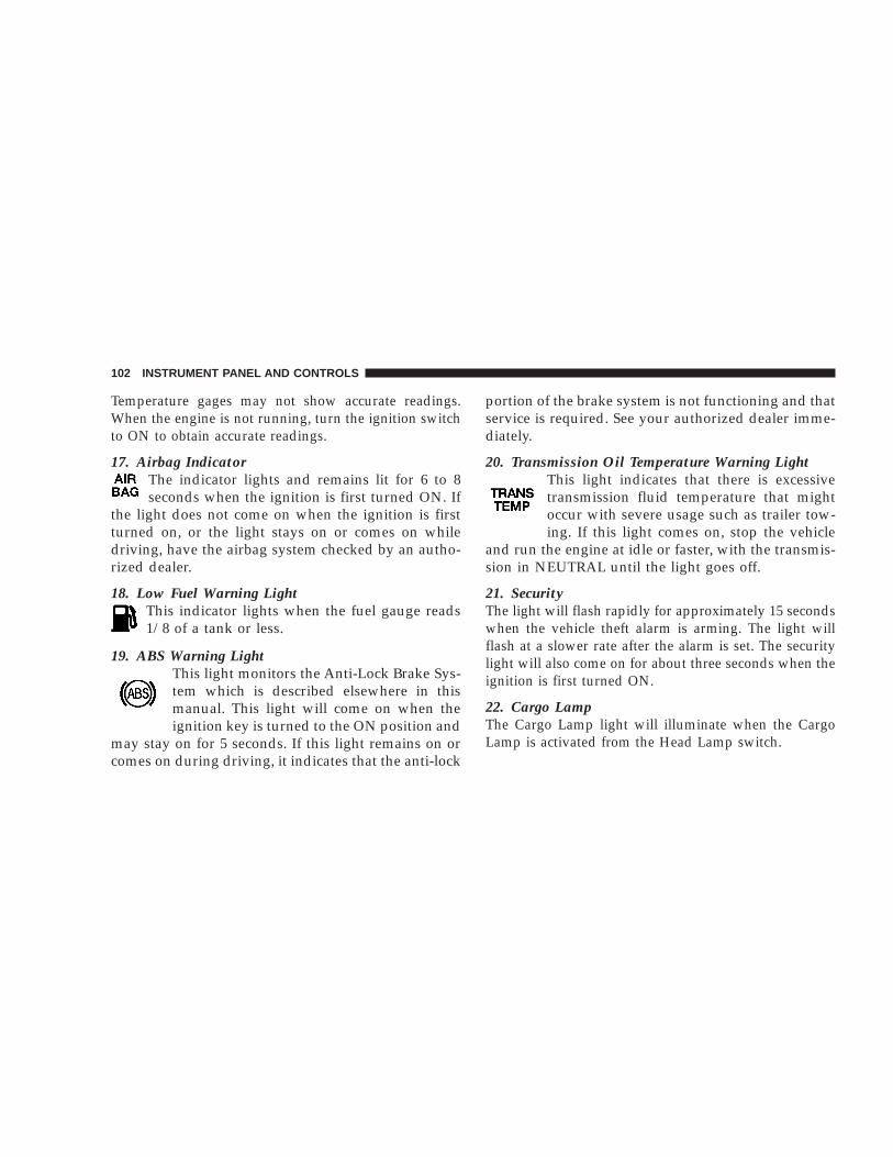
Temperature gages may not show accurate readings.When the engine is not running, turn the ignition switchto ON to obtain accurate readings.
17. Airbag IndicatorThe indicator lights and remains lit for 6 to 8seconds when the ignition is first turned ON. If
the light does not come on when the ignition is firstturned on, or the light stays on or comes on whiledriving, have the airbag system checked by an autho-rized dealer.
18. Low Fuel Warning LightThis indicator lights when the fuel gauge reads1/8 of a tank or less.
19. ABS Warning LightThis light monitors the Anti-Lock Brake Sys-tem which is described elsewhere in thismanual. This light will come on when theignition key is turned to the ON position and
may stay on for 5 seconds. If this light remains on orcomes on during driving, it indicates that the anti-lock
portion of the brake system is not functioning and thatservice is required. See your authorized dealer imme-diately.
20. Transmission Oil Temperature Warning LightThis light indicates that there is excessivetransmission fluid temperature that mightoccur with severe usage such as trailer tow-ing. If this light comes on, stop the vehicle
and run the engine at idle or faster, with the transmis-sion in NEUTRAL until the light goes off.
21. SecurityThe light will flash rapidly for approximately 15 secondswhen the vehicle theft alarm is arming. The light willflash at a slower rate after the alarm is set. The securitylight will also come on for about three seconds when theignition is first turned ON.
22. Cargo LampThe Cargo Lamp light will illuminate when the CargoLamp is activated from the Head Lamp switch.
102 INSTRUMENT PANEL AND CONTROLS

23. Malfunction Indicator LightThis light is part of an onboard diagnosticsystem which monitors the emissions and en-gine control system. If the vehicle is ready for
emissions testing the light will come on when theignition is first turned on and remain on, as a bulbcheck, until the engine is started. If the vehicle is notready for emissions testing the light will come onwhen the ignition is first turned on and remain on for15 seconds, then blink for 5 seconds, and remain onuntil the vehicle is started. If the bulb does not comeon during starting, have the condition investigatedpromptly.
If this light comes on and remains on while driving, itsuggests a potential engine control problem and the needfor system service.
Although your vehicle will usually be drivable and notneed towing, see your dealer for service as soon aspossible.
CAUTION!
Prolonged driving with the MIL on could causedamage to the engine control system. It also couldaffect fuel economy and driveability.
If the MIL is flashing, severe catalytic converterdamage and power loss will soon occur. Immediateservice is required.
24. Door AjarThe Door Ajar light will illuminate when theignition is ON and either one of the passen-ger doors is opened.
25. Odometer/Trip Odometer ButtonPress this button to toggle between the odometer and thetrip odometer display. Holding the button in resets thetrip odometer reading.
26. Odometer/Trip OdometerThe odometer shows the total distance the vehicle hasbeen driven.
INSTRUMENT PANEL AND CONTROLS 103
4

U.S. federal regulations require that upon transfer ofvehicle ownership, the seller certify to the purchaser thecorrect mileage that the vehicle has been driven. There-fore, if the odometer reading is changed during repair orreplacement, be sure to keep a record of the readingbefore and after the service so that the correct mileage canbe determined.
The trip odometer shows individual trip mileage. Totoggle between the odometer and the trip odometer,press the Odometer/Trip Odometer Button.
27. Cruise LightThis indicator lights when the electronic speed controlsystem is turned on.
28. Coolant Temperature Light (Clusters Without AGauge)
This light warns of an overheated engine con-dition. For a bulb check, this light will come onmomentarily when the ignition is turned On. If
the light turns on while driving, stop the vehicle andshut off the engine as soon as possible.
CAUTION!
Driving with a hot engine cooling system coulddamage your vehicle. If the temperature light is on,pull over and stop the vehicle. Idle the vehicle withthe air conditioner turned off until the light turnsoff. If the if the light remains on, turn the engine offimmediately, and call for service.
WARNING!
A hot engine cooling system is dangerous. You orothers could be badly burned by steam or boilingcoolant. You may want to call a service center if yourvehicle overheats. If you decide to look under thehood yourself, see Section 7 of this manual. Followthe warnings under the Cooling System PressureCap paragraph.
104 INSTRUMENT PANEL AND CONTROLS

29. Engine Oil Pressure Indicator Light (ClustersWithout A Gauge)
This light indicates that the engine oil pressurehas become too low. For a bulb check, this light
will come on momentarily when the ignition is turnedOn. If the light turns on while driving, stop the vehicleand shut off the engine as soon as possible. Immediateservice should be obtained.
30. Voltage Light (Clusters Without A Gauge)This light monitors the electrical system volt-age. The light should turn on momentarily as
the engine is started. If the light stays on or turns onwhile driving, it indicates a problem with the chargingsystem. Immediate service should be obtained.
ELECTRONIC DIGITAL CLOCK
The clock and radio each use the display panel built intothe radio. A digital readout shows the time in hours andminutes whenever the ignition switch is in the “ON” or“ACC” position.
When the ignition switch is in the “OFF” position, orwhen the radio frequency is being displayed, time keep-ing is accurately maintained.
Clock Setting Procedure
1. Turn the ignition switch to the “ON” or “ACC”position. Using the point of a ballpoint pen or similarobject, press either the “H” (Hour) or “M” (Minute)buttons on the radio. The display will show the time.
2. Press the “H” button to set hours or the “M” button toset minutes. The time setting will increase each time youpress a button.
INSTRUMENT PANEL AND CONTROLS 105
4

SALES CODE RAZ—AM/ FM STEREO RADIOWITH CASSETTE TAPE PLAYER, CD PLAYERAND CD CHANGER CONTROLS — IF EQUIPPED
Operating Instructions — Radio
NOTE: Power to operate the radio is controlled by theignition switch. It must be in the ON or ACC position tooperate the radio.
Power Switch, Volume ControlPress the ON/VOL control to turn the radio on. Turn thevolume control clockwise to increase the volume. Thevolume will be displayed and continuously updatedwhile the button is pressed.
Seek Button (Radio Mode)Press and release the Seek button to search for the nextstation in either the AM or FM mode. Press the top of thebutton to seek up and the bottom to seek down. Holdingthe button will by pass stations until you release thebutton.
TuningPress the TUNE control up or down to increase ordecrease the frequency. If you press and hold the button,the radio will continue to tune until you release thebutton. The frequency will be displayed and continu-ously updated while the button is pressed.
PTY (Program Type) ButtonPressing this button once will turn on the PTY mode for5 seconds. If no action is taken during the 5 second timeout the PTY icon will turn off. Pressing the PTY buttonwithin 5 seconds will allow the program format type tobe selected. Many radio stations do not currently broad-cast PTY information.
106 INSTRUMENT PANEL AND CONTROLS

Toggle the PTY button to select the following formattypes:
Program Type Radio DisplayAdult Hits Adlt HitClassical ClassiclClassic Rock Cls RockCollege CollegeCountry CountryInformation InformJazz JazzForeign Language LanguageNews NewsNostalgia NostalgaOldies OldiesPersonality PersnltyPublic PublicRhythm and Blues R & BReligious Music Rel MuscReligious Talk Rel TalkRock Rock
Program Type Radio DisplaySoft SoftSoft Rock Soft RckSoft Rhythm and Blues Soft R&BSports SportsTalk TalkTop 40 Top 40Weather Weather
By pressing the SEEK button when the PTY icon isdisplayed, the radio will be tuned to the next frequencystation with the same selected PTY name. The PTYfunction only operates when in the FM mode.
The radio display will flash “SEEK” and the selected PTYprogram type when searching for the next PTY station. Ifno station is found with the selected PTY program type,the radio will return to the last preset station.
If a preset button is activated while in the PTY (ProgramType) mode, the PTY mode will be exited and the radiowill tune to the preset station.
INSTRUMENT PANEL AND CONTROLS 107
4

Pressing PTY, then SCAN will scan the FM Band and stopat all RDS stations. Each RDS station will be played for a5 second scan once around the FM Band and stop at thelast station. The PTY icon will then turn off.
BalanceThe Balance control adjusts the left-to-right speaker bal-ance. Push in the button and it will pop out. Adjust thebalance and push the button back in. The balance will bedisplayed and continuously updated while the button isturned.
FadeThe Fade control provides for balance between the frontand rear speakers. Push in the button and it will pop out.Adjust the balance and push the button back in. The fadewill be displayed and continuously updated while thebutton is turned.
Tone ControlSlide the Bass and/or Treble controls up or down toadjust the sound for the desired tone. The treble, and basswill be displayed and continuously updated while theslide is moved.
AM/FM SelectionPress the AM/FM button to change from AM to FM. Theoperating mode will be displayed next to the stationfrequency. The display will show ST when a stereostation is received.
Scan ButtonPressing the SCAN button causes the tuner to search forthe next station, in either AM or FM, pausing for 5seconds at each listenable station before continuing to thenext.
Pressing the AM/FM button continues the search in thealternate frequency band.
To stop the search, press SCAN a second time.
To Set The Radio Push-button MemoryWhen you are receiving a station that you wish tocommit to push-button memory, press the SET button.SET 1 will show in the display window. Select thepush-button you wish to lock onto this station and pressand release that button. If a station is not selected within
108 INSTRUMENT PANEL AND CONTROLS

5 seconds after pressing the SET button, the station willcontinue to play but will not be locked into push-buttonmemory.
You may add a second station to each push-button byrepeating the above procedure with this exception: Pressthe SET button twice and SET 2 will show in the displaywindow. Each button can be set for SET 1 and SET 2 inboth AM and FM. This allows a total of 10 AM and 10 FMstations to be locked into memory. You can recall thestations stored in SET 2 memory by pressing the push-button twice.
To Change From Clock To Radio ModePress the Time button to change the display betweenradio frequency and time.
Operating Instructions — Tape PlayerInsert the cassette with the exposed tape side toward theright and the mechanical action of the player will gentlypull the cassette into the play position.
NOTE: When subjected to extremely cold temperatures,the tape mechanism may require a few minutes to warmup for proper operation. Sometimes poor playback may
be experienced due to a defective cassette tape. Clean anddemagnetize the tape heads at least twice a year.
Seek ButtonPress the SEEK button up for the next selection on thetape and down to return to the beginning of the currentselection.
Press the SEEK button up or down to move the tracknumber to skip forward or backward 1 to 6 selections.Press the SEEK button once to move 1 selection, twice tomove 2 selections, etc.
Fast Forward (FF)Press the FF button up momentarily to advance the tapein the direction that it is playing. The tape will advanceuntil the button is pressed again or the end of the tape isreached. At the end of the tape, the tape will play in theopposite direction.
Rewind (RW)Press the RW button momentarily to reverse the tapedirection. The tape will reverse until the button is pressedagain or until the end of the tape is reached. At the end ofthe tape, the tape will play in the opposite direction.
INSTRUMENT PANEL AND CONTROLS 109
4

Tape EjectPress the EJT Tape button and the cassette will disengageand eject from the radio.
Scan ButtonPress this button to play 10 seconds of each selection.Press the scan button a second time to cancel the feature.
Changing Tape DirectionIf you wish to change the direction of tape travel (sidebeing played), press the PTY button. The lighted arrow inthe display window will show the new direction.
Metal Tape SelectionIf a standard metal tape is inserted into the player, theplayer will automatically select the correct equalizationand the 70 symbol will appear in the display window.
Pinch Roller ReleaseIf ignition power or the radio ON/OFF switch are turnedoff, the pinch roller will automatically retract to protectthe tape from any damage. When power is restored to thetape player, the pinch roller will automatically reengageand the tape will resume play.
Noise ReductionThe Dolby Noise Reduction System* is on whenever thetape player is on, but may be switched off.
To turn off the Dolby Noise reduction System: Press theDolby button (button 2) after you insert the tape. The NRlight in the display will go off when the Dolby System isoff. The Dolby System is automatically reactivated eachtime a tape is inserted.
* ”Dolby” noise reduction manufactured under licensefrom Dolby Laboratories Licensing Corporation. Dolbyand the double-D symbol are trademarks of Dolby Labo-ratories Licensing Corporation.
Operating Instructions — CD Player
NOTE: The ignition switch must be in the ON or ACCposition and the volume control ON before the CD playerwill operate.
110 INSTRUMENT PANEL AND CONTROLS

CAUTION!
This CD player will accept 4 3⁄4 inch (12 cm) discsonly. The use of other sized discs may damage theCD player mechanism.
Inserting The Compact DiscThe CD player contained within the radio is not amulti-disc changer, and will only accept one CD. Gentlyinsert one CD into the CD player with the CD label facingup. The CD will automatically be pulled into the CDPlayer.
If the volume control is ON, the unit will switch fromradio to CD mode and begin to play. The display willshow the track number and index time in minutes andseconds. Play will begin at the start of track one.
NOTE:• You may eject a disc with the radio OFF. The ignition
switch must be in the ON or ACC position to insert adisc with the radio OFF.
• If you insert a disc with the ignition ON and the radioOFF, the CD will automatically be pulled into the CDPlayer and the display will show the time of day. Ifyou insert a disc with the ignition OFF, the display willshow the time of day for about 5 seconds, then go out.
Seek ButtonPress the top of the SEEK button for the next selection onthe CD. Press the bottom of the button to return to thebeginning of the current selection, or return to thebeginning of the previous selection if the CD is within thefirst 10 seconds of the current selection.
EJT CD (Eject) ButtonPress this button and the disc will unload and move tothe entrance for easy removal. The unit will switch to theradio mode.
If you do not remove the disc within 15 seconds, it will bereloaded. The radio mode will continue to appear.
The disc can be ejected with the radio OFF.
INSTRUMENT PANEL AND CONTROLS 111
4

FF/TUNE/RWPress FF (Fast Forward) and the CD player will begin tofast forward until FF is released. The RW ( Reverse)button works in a similar manner.
Program Button 4 (Random Play)Press this button while the CD is playing to activateRandom Play. This feature plays the tracks on the se-lected disc in random order to provide an interestingchange of pace.
Press the SEEK button to move to the next randomlyselected track.
Press TUNE FF to fast forward through the tracks. Pressthe FF button a second time to stop the fast forwardfeature. If TUNE RW is pressed, the current track willreverse to the beginning of the track and begin playing.
Press button 4 a second time to stop Random Play.
MODEPress the MODE button to select between the tape player,CD player, or satellite radio (if equipped).
To select Satellite Radio (if equipped), press the MODEbutton until the word SIRIUS appears. The following willbe displayed in this order: After three seconds, thecurrent channel name and number will be displayed forfive seconds. The current program type and channelnumber will then be displayed for five seconds. Thecurrent channel name and number will then be displayeduntil an action occurs. A CD or tape may remain in theplayer while in the Satellite Radio mode.
Tape CD ButtonPress this button to select between CD player and Tapeplayer.
Time ButtonPress this button to change the display from elapsed CDplaying time to time of day.
Scan ButtonPress this button to play the first 10 seconds of each track.To stop the scan function, press the button a second time.
112 INSTRUMENT PANEL AND CONTROLS

CD Changer Control Capability — If EquippedThis radio is compatible with a remote mounted CDchanger available through Mopar Accessories. The fol-lowing instructions are for the radio controls that operatethis CD changer.
Mode ButtonTo activate the CD changer, press the MODE button untilCD information appears on the display.
Push-ButtonWhile the CD changer is playing, press the NUMBER 1push-button or the NUMBER 5 push-button to select adisc numbered higher or lower than the one currentlybeing played.
Seek ButtonPress the SEEK up or down to select another track on thesame disc. A SEEK symbol will appear on the display.
Fast Forward And Rewind ButtonsPress and hold the FF button for fast forward. Press andhold the RW button for fast reverse.
The audio output can be heard when fast forward andfast reverse are activated.
Random Play (RND)Press the Random button to play the tracks on theselected disc in random order for an interesting change ofpace.
Random can be cancelled by pressing the button a secondtime or by ejecting the CD from the changer.
CD Diagnostic IndicatorsWhen driving over a very rough road, the CD player mayskip momentarily. Skipping will not damage the disc orthe player, and play will resume automatically.
As a safeguard and to protect your CD player, one of thefollowing warning symbols may appear on your display.
A CD HOT symbol indicates the player is too hot.
CD HOT will pause the operation. Play can be resumedwhen the operating temperature is corrected or anotherMODE is selected.
An ERR symbol will appear on the display if the laser isunable to read the Disc data for the following reasons:
• Excessive vibration
INSTRUMENT PANEL AND CONTROLS 113
4

• Disc inserted upside down
• Damaged disc
• Water condensation on optics
SALES CODE RBK—AM/ FM STEREO RADIOWITH CD PLAYER AND CD CHANGERCONTROLS
Radio Operation
Power/Volume ControlPress the ON/VOL control to turn the radio on. Turn thevolume control clockwise to increase the volume.
NOTE: Power to operate the radio is supplied throughthe ignition switch. It must be in the ON or ACC positionto operate the radio.
SeekPress and release the SEEK button to search for the nextstation in either the AM or FM mode. Press the top of thebutton to seek up and the bottom to seek down. Theradio will remain tuned to the new station until youmake another selection. Holding the button in will by-pass stations without stopping until you release it.
TunePress the TUNE control up or down to increase ordecrease the frequency. If you press and hold the button,the radio will continue to tune until you release thebutton. The frequency will be displayed and continu-ously updated while the button is pressed.
114 INSTRUMENT PANEL AND CONTROLS

BalanceThe Balance control adjusts the left-to-right speaker bal-ance. Press the BAL button in and it will pop out. Adjustthe balance and push the button back in.
FadeThe Fade control provides for balance between the frontand rear speakers. Press the FADE button in and it willpop out. Adjust the balance and push the button back in.
Bass and Treble Tone ControlThe tone controls consist of 2 separate bands. The bassband is on the left, and the treble band is on the right.Each band is adjusted by a slider control with a detent atthe mid-position. Moving the control up or down in-creases or decreases amplification of that band. The midposition provides a balanced output.
AM/FM SelectionPress the AM/FM button to change from AM to FM. Theoperating mode will be displayed next to the stationfrequency. The display will show ST when a stereostation is received.
To Set The Radio Push-Button MemoryWhen you are receiving a station that you wish tocommit to push-button memory, press the SET button.SET 1 will show in the display window. Select the “1–5”button you wish to lock onto this station and press andrelease that button. If a button is not selected within 5seconds after pressing the SET button, the station willcontinue to play but will not be locked into push-buttonmemory.
You may add a second station to each push-button byrepeating the above procedure with this exception: Pressthe SET button twice and SET 2 will show in the displaywindow. Each button can be set for SET 1 and SET 2 inboth AM and FM. This allows a total of 10 AM and 10 FMstations to be locked into push-button memory. Thestations stored in SET 2 memory can be selected bypressing the push-button twice. Every time a presetbutton is used a corresponding button number will bedisplayed.
TimePress the TIME button to change the display betweenradio frequency and time.
INSTRUMENT PANEL AND CONTROLS 115
4

General InformationThis radio complies with Part 15 of FCC rules and withRSS-210 of Industry Canada. Operation is subject to thefollowing conditions:
1. This device may not cause harmful interference,
2. This device must accept any interference received,including interference that may cause undesired opera-tion.
NOTE: Changes or modifications not expressively ap-proved by the party responsible for compliance couldvoid the user’s authority to operate the equipment.
CD Player Operation
NOTE: The ignition switch must be in the ON or ACCposition and the volume control ON before the CD playerwill operate.
Inserting The Compact Disc
CAUTION!
This CD player will accept 4 3⁄4 inch (12 cm) discsonly. The use of other sized discs may damage theCD player mechanism.
You may either insert or eject a disc with the radio OFF.
If you insert a disc with the ignition ON and the radioOFF, the display will show the time of day.
If the power is ON, the unit will switch from radio to CDmode and begin to play when you insert the disc. Thedisplay will show the track number and index time inminutes and seconds. Play will begin at the start of trackone.
SeekPress the top of the SEEK button for the next selection onthe CD. Press the bottom of the button to return to the
116 INSTRUMENT PANEL AND CONTROLS

beginning of the current selection, or return to thebeginning of the previous selection if the CD is within thefirst second of the current selection.
EJT — EjectPress the EJT button and the disc will unload and moveto the entrance for easy removal. The unit will switch tothe radio mode.
If you do not remove the disc within 15 seconds, it will bereloaded. The unit will continue in radio mode.
The disc can be ejected with the radio and ignition OFF.
FF/TUNE/RWPress FF (Fast Forward) and the CD player will begin tofast forward until FF is released. The RW ( Reverse)button works in a similar manner.
Random Play — RND/Program Button 4Press the RND (button 4) button while the CD is playingto activate Random Play. This feature plays the tracks onthe selected disc in random order to provide an interest-ing change of pace.
Press the SEEK button to move to the next randomlyselected track.
Press the RND (button 4) button a second time to stopRandom Play.
ModePress the MODE button repeatedly to select between theCD player, the optional remote CD changer and theSatellite Radio (if equipped). When Satellite Radio (ifequipped) is selected “SA” will appear in your radiodisplay.
A CD or tape may remain in the player while in theSatellite mode.
TimePress the TIME button to change the display fromelapsed CD playing time to time of day.
CD Changer Control Capability — If EquippedThis radio is compatible with a remote mounted CDchanger available through Mopar Accessories. The fol-lowing instructions are for the radio controls that operatethis CD changer.
INSTRUMENT PANEL AND CONTROLS 117
4
Mode ButtonTo activate the CD changer, press the MODE button untilCD information appears on the display.
Push-ButtonWhile the CD changer is playing, press the NUMBER 1push-button or the NUMBER 5 push-button to select adisc numbered higher or lower than the one currentlybeing played.
Seek ButtonPress the SEEK up or down to select another track on thesame disc. A SEEK symbol will appear on the display.
Fast Forward And Rewind ButtonsPress and hold the FF button for fast forward. Press andhold the RW button for fast reverse.
The audio output can be heard when fast forward andfast reverse are activated.
Random Play (RND)Press the Random button to play the tracks on theselected disc in random order for an interesting change ofpace.
Random can be cancelled by pressing the button a secondtime or by ejecting the CD from the changer.
CD Diagnostic IndicatorsWhen driving over a very rough road, the CD player mayskip momentarily. Skipping will not damage the disc orthe player, and play will resume automatically.
As a safeguard and to protect your CD player, one of thefollowing warning symbols may appear on your display.
A CD HOT symbol indicates the player is too hot.
CD HOT will pause the operation. Play can be resumedwhen the operating temperature is corrected or anotherMODE is selected.
An ERR symbol will appear on the display if the laser isunable to read the Disc data for the following reasons:
• Excessive vibration
• Disc inserted upside down
• Damaged disc
• Water condensation on optics
118 INSTRUMENT PANEL AND CONTROLS

Radio Display MessagesYour radio has been designed to display certain messageswhen a problem is detected with the CD player.
SALES CODE RBB—AM/FM STEREO RADIOWITH CASSETTE TAPE PLAYER AND CDCHANGER CAPABILITY
Operating Instructions
NOTE: Power to operate the radio is supplied throughthe ignition switch. It must be in the ON or ACC positionto operate the radio.
NOTE: When first learning the control functions, theuser should set the controls as shown in the followinglist.Tone Controls…As illustrated.Speaker Control…Centered.
INSTRUMENT PANEL AND CONTROLS 119
4

Power ButtonThe volume control/power button pops out whenpressed, this turns the sound system ON in the mode lastused. Pushing the button back in turns the sound systemOFF.
Electronic Volume ControlThe electronic volume control turns continuously (360degrees) in either direction without stopping. Turning thevolume control to the right increases the volume and tothe left decreases it.
When the audio system is turned on, the sound will beset at the same volume level as last played.
For your convenience, the volume can be turned down,but not up, when the audio system is off and the ignitionis ON.
SeekPress and release the SEEK button to search for the nextstation in either the AM or FM mode. Press the top of thebutton to seek up and the bottom to seek down. Theradio will remain tuned to the new station until you
make another selection. Holding the button will bypassstations without stopping until you release it.
TunePress the TUNE control up or down to increase ordecrease the frequency. If the button is pushed and held,the radio will continue to tune until the button isreleased. The frequency will be displayed and continu-ously updated while the button is pushed.
To Set The Push-Button MemoryWhen you are receiving a station that you wish tocommit to push-button memory, press the SET button.The symbol SET 1 will now show in the display window.Select the “1–5” button you wish to lock onto this stationand press and release that button. If a button is notselected within 5 seconds after pressing the SET button,the station will continue to play but will not be lockedinto push-button memory.
You may add a second station to each push-button byrepeating the above procedure with this exception: Pressthe SET button twice and SET 2 will show in the displaywindow. Each button can be set for SET 1 and SET 2 inboth AM and FM. This allows a total of 10 AM and 10 FM
120 INSTRUMENT PANEL AND CONTROLS

stations to be locked into push-button memory. Thestations stored in SET 2 memory can be selected bypressing the push-button twice.
Every time a preset button is used a correspondingbutton number will be displayed.
BalanceThe balance control adjusts the left-to-right speaker bal-ance. Press the BAL button in and it will pop out. Adjustthe balance and push the button back in.
FadeThe fade control provides for balance between the frontand rear speakers. Press the FADE button in and it willpop out. Adjust the balance and push the button back in.
Bass and Treble Tone ControlThe tone controls consist of 2 separate bands. The bassband is on the left, and the treble band is on the right.Each band is adjusted by a slider control with a detent atthe mid-position. Moving the control up or down in-creases or decreases amplification of that band. The midposition provides a balanced output.
AM/FM SelectionPress the AM/FM button to change from AM to FM. Theoperating mode will be displayed next to the stationfrequency. The display will show ST when a stereostation is received in the FM mode.
Mode ButtonPress the MODE button to select between the cassettetape player, CD changer, or the Satellite Radio (ifequipped). When the Satellite Radio (if equipped) isselected “SA” will appear in your radio display.
A CD or tape may remain in the player while in theSatellite or radio mode.
Cassette Player FeaturesWith ignition OFF and the sound system OFF, you caneject the tape cassette by pushing the EJECT button.
You can turn the tape player ON by inserting a cassette oractivating the MODE button (with a cassette in the radio),but only when the ignition and radio are on.
Each time a cassette is inserted the tape player will beginplaying on the side of the cassette that is facing up in theplayer.
INSTRUMENT PANEL AND CONTROLS 121
4

Music SearchPressing the SEEK button while playing a tape will startthe Music Search mode. Press the SEEK button up for thenext selection on the tape and down to return to thebeginning of the current selection, or return to thebeginning of the previous selection if the tape is withinthe first 5 seconds of the current selection.
The SEEK symbol appears on the display when MusicSearch is in operation. Music Search shuts off automati-cally when a selection has been located.
Selective Music SearchPress the SEEK button up or down to move the tracknumber to skip forward or backward 1 to 7 selections.Press the SEEK button once to move 1 selection, twice tomove 2 selections, etc.
Fast Forward And Rewind ButtonsPressing the TUNE button up or down momentarilyactivates Fast Forward or Rewind and makes the direc-tional arrows appear on the display.
To stop Fast Forward or Rewind, press the TUNE buttonagain.
Time ButtonPress the time button to toggle between station frequencyand time of day.
Pressing this button while playing a cassette tape willchange the side of the tape being played.
NR (Noise Reduction)Pushing the Number 2 Pre-set button when a tape isplaying deactivates the Dolby Noise Reduction System*.When Dolby is ON, the NR symbol appears on thedisplay. Each time a tape is inserted the Dolby will turnON.
* “Dolby” noise reduction manufactured under licensefrom Dolby Laboratories Licensing Corporation. Dolbyand the double-D symbol are trademarks of Dolby Labo-ratories Licensing Corporation.
CD Changer Control Capability — If EquippedThis radio is compatible with a remote mounted CDchanger available through Mopar Accessories. The fol-lowing instructions are for the radio controls that operatethis CD changer.
122 INSTRUMENT PANEL AND CONTROLS

Mode ButtonTo activate the CD changer, press the MODE button untilCD information appears on the display.
Push-ButtonWhile the CD changer is playing, press the NUMBER 1push-button or the NUMBER 5 push-button to select adisc numbered higher or lower than the one currentlybeing played.
Seek ButtonPress the SEEK up or down to select another track on thesame disc. A SEEK symbol will appear on the display.
Fast Forward And Rewind ButtonsPress and hold the FF button for fast forward. Press andhold the RW button for fast reverse.
The audio output can be heard when fast forward andfast reverse are activated.
Random Play (RND)Press the Random button to play the tracks on theselected disc in random order for an interesting change ofpace.
Random can be cancelled by pressing the button a secondtime or by ejecting the CD from the changer.
CD Diagnostic IndicatorsWhen driving over a very rough road, the CD player mayskip momentarily. Skipping will not damage the disc orthe player, and play will resume automatically.
As a safeguard and to protect your CD player, one of thefollowing warning symbols may appear on your display.
A CD HOT symbol indicates the player is too hot.
CD HOT will pause the operation. Play can be resumedwhen the operating temperature is corrected or anotherMODE is selected.
An ERR symbol will appear on the display if the laser isunable to read the Disc data for the following reasons:
• Excessive vibration
• Disc inserted upside down
• Damaged disc
• Water condensation on optics
INSTRUMENT PANEL AND CONTROLS 123
4

Radio Display MessagesYour radio has been designed to display certain messageswhen a problem is detected with the CD player.
SALES CODE RBQ—AM/FM STEREO RADIOWITH 6 - DISC CD CHANGER
Radio Operation
Power/Volume ControlPress the PWR/VOL control to turn the radio on. Turnthe volume control clockwise to increase the volume.
NOTE: Power to operate the radio is controlled by theignition switch. It must be in the ON or ACC position tooperate the radio.
124 INSTRUMENT PANEL AND CONTROLS

ModePress the MODE button repeatedly to select between AM,FM, the CD changer and Sirius Satellite Radio™ (ifequipped). The display will show ST when a stereostation is received.
To select Sirius Satellite Radio™ (if equipped), press theMODE button until the word SIRIUS appears. The fol-lowing will be displayed in this order: After three sec-onds, the current channel name and number will bedisplayed for five seconds. The current program type andchannel number will then be displayed for five seconds.The current channel name and number will then bedisplayed until an action occurs. CD’s may remain in theplayer while in the Satellite Radio mode.
SeekPress and release the SEEK button to search for the nextstation in either the AM or FM mode. Press the top of thebutton to seek up and the bottom to seek down. Theradio will remain tuned to the new station until youmake another selection. Holding the button in will by-pass stations without stopping until you release it.
TunePress the TUNE control up or down to increase ordecrease the frequency. If the button is pressed and held,the radio will continue to tune until the button isreleased. The frequency will be displayed and continu-ously updated while the button is pressed.
Balance — BALThe Balance control adjusts the left-to-right speaker bal-ance. Press the BAL button in and it will pop out. Adjustthe balance and push the button back in.
FadeThe Fade control provides for balance between the frontand rear speakers. Press the FADE button in and it willpop out. Adjust the balance and push the button back in.
Tone ControlThe tone controls affect the Bass and Treble frequencybands. Each is controlled by a slider control with a detentat the mid position. Moving a control up or downincreases or decreases amplification of the band. The midposition provides a balanced output.
INSTRUMENT PANEL AND CONTROLS 125
4

To Set The Radio Push-Button MemoryWhen you are receiving a station that you wish tocommit to push-button memory, press the SET RNDbutton. SET 1 will show in the display window. Select the“1–6” button you wish to lock onto this station and pressand release that button. If a button is not selected within5 seconds after pressing the SET RND button, the stationwill continue to play but will not be locked into push-button memory.
You may add a second station to each push-button byrepeating the above procedure with this exception: Pressthe SET button twice and SET 2 will show in the displaywindow. Each button can be set for SET 1 and SET 2 inboth AM and FM. This allows a total of 12 AM and 12 FMstations to be locked into push-button memory. Thestations stored in SET 2 memory can be selected bypressing the corresponding push-button twice. Everytime a preset button is used, a corresponding buttonnumber will be displayed.
Time ButtonPress the TIME button to change the display betweenradio frequency and time.
General InformationThis radio complies with Part 15 of FCC rules and withRSS-210 of Industry Canada. Operation is subject to thefollowing conditions:
1. This device may not cause harmful interference,
2. This device must accept any interference received,including interference that may cause undesired opera-tion.
NOTE: Changes or modifications not expressively ap-proved by the party responsible for compliance couldvoid the user’s authority to operate the equipment.
CD Player Operation
NOTE: The ignition switch must be in the ON or ACCposition and the Power / Volume control pushed ONbefore the CD player will operate.
126 INSTRUMENT PANEL AND CONTROLS

Inserting The Compact Disc
CAUTION!
This CD player will accept 4 3⁄4 inch (12 cm) discsonly. The use of other sized discs may damage theCD player mechanism.
You may either insert or eject a disc with the radio OFF.
If you insert a disc with the ignition ON and the radioOFF, the display will show the time of day. If you inserta disc with the ignition OFF, the display will show thetime of day for about 5 seconds, then go out.
If you insert a disc with the ignition ON and the radioON, the unit will switch from radio to CD mode andbegin to play when you insert the disc. The display willshow the disc number, the track number, and index timein minutes and seconds. Play will begin at the start oftrack 1.
LOAD/ EJT — LoadPress the LOAD/ EJT button and the button with thecorresponding number where the CD is being loaded.After the radio displays “load” insert the CD into theplayer.
Radio display will show “loading” when it is beingloaded.
LOAD / EJT — EjectPress the LOAD/ EJT button and the button with thecorresponding number where the CD was loaded and thedisc will unload and move to the entrance for easyremoval.
Radio display will show “ejecting” when it is beingejected.
If you have ejected a disc and have not removed it within15 seconds, it will be reloaded. If the CD is not removed,the radio will continue to play the non-removed CD. Ifthe CD is removed and there are other CD’s in the radio,the radio will play the next CD. If the CD is removed andthere are no other CD’s in the radio, the radio will returnto the last selected AM or FM mode.
INSTRUMENT PANEL AND CONTROLS 127
4

The disc can be ejected with the radio and ignition OFF.
SeekPress the top of the SEEK button for the next selection onthe CD. Press the bottom of the button to return to thebeginning of the current selection, or return to thebeginning of the previous selection if the CD is within thefirst second of the current selection.
ScanPress the Scan button to scan through each track on theCD currently playing.
FF/TUNE/RWPress FF (Fast Forward) and the CD player will begin tofast forward until FF is released. The RW ( Reverse)button works in a similar manner.
Random Play — SET / RNDPress the RND button while the CD is playing to activateRandom Play. This feature plays the tracks on the disc inrandom order to provide an interesting change of pace.
Press the SEEK button to move to the next randomlyselected track.
Press TUNE FF to fast forward through the tracks. Pressthe FF button a second time to stop the fast forwardfeature. If TUNE RW is pressed, the current track willreverse to the beginning of the track and begin playing.
Press the SET / RND button a second time to stopRandom Play.
PTY (Program Type) ButtonPressing this button once will turn on the PTY mode for5 seconds. If no action is taken during the 5 second timeout the PTY icon will turn off. Pressing the PTY buttonwithin 5 seconds will allow the program format type tobe selected. Many radio stations do not currently broad-cast PTY information.
Toggle the PTY button to select the following formattypes:
Program Type Radio DisplayAdult Hits Adlt HitClassical ClassiclClassic Rock Cls RockCollege CollegeCountry Country
128 INSTRUMENT PANEL AND CONTROLS

Program Type Radio DisplayEmergency ALERT!Emergency Test TestInformation InformJazz JazzForeign Language LanguageNews NewsNostalgia NostalgaOldies OldiesPersonality PersnltyPublic PublicRhythm and Blues R & BReligious Music Rel MuscReligious Talk Rel TalkRock RockSoft SoftSoft Rock Soft RckSoft Rhythm and Blues Soft R&BSports SportsTalk TalkTop 40 Top 40Weather Weather
By pressing the SEEK button when the PTY icon isdisplayed, the radio will be tuned to the next frequencystation with the same selected PTY name. The PTYfunction only operates when in the FM mode.
The radio display will flash “SEEK” and the selected PTYprogram type when searching for the next PTY station. Ifno station is found with the selected PTY program type,the radio will return to the last station.
If a preset button is activated while in the PTY (ProgramType) mode, the PTY mode will be exited and the radiowill tune to the preset station.
By pressing the SCAN button when the PTY icon isdisplayed, the radio will stop at every PTY station on theband and list each corresponding program type in theradio display.
TimePress the TIME button to change the display fromelapsed CD playing time to time of day.
INSTRUMENT PANEL AND CONTROLS 129
4
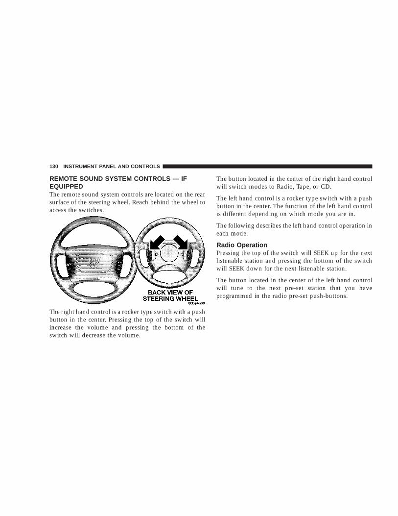
REMOTE SOUND SYSTEM CONTROLS — IFEQUIPPEDThe remote sound system controls are located on the rearsurface of the steering wheel. Reach behind the wheel toaccess the switches.
The right hand control is a rocker type switch with a pushbutton in the center. Pressing the top of the switch willincrease the volume and pressing the bottom of theswitch will decrease the volume.
The button located in the center of the right hand controlwill switch modes to Radio, Tape, or CD.
The left hand control is a rocker type switch with a pushbutton in the center. The function of the left hand controlis different depending on which mode you are in.
The following describes the left hand control operation ineach mode.
Radio OperationPressing the top of the switch will SEEK up for the nextlistenable station and pressing the bottom of the switchwill SEEK down for the next listenable station.
The button located in the center of the left hand controlwill tune to the next pre-set station that you haveprogrammed in the radio pre-set push-buttons.
130 INSTRUMENT PANEL AND CONTROLS
Tape PlayerPressing the top of the switch once will go to the nextselection on the cassette. Pressing the bottom of theswitch once will go to the beginning of the currentselection or to the beginning of the previous selection if itis within the first 5 seconds of the current selection.
If you press the switch up or down twice it plays thesecond selection, three times, it will play the third, etc.
The button in the center of the left hand switch has nofunction in this mode.
CD PlayerPressing the top of the switch once will go to the nexttrack on the CD. Pressing the bottom of the switch oncewill go to the beginning of the current track or to thebeginning of the previous track if it is within one secondafter the current track begins to play.
If you press the switch up or down twice it plays thesecond track, three times, it will play the third, etc.
The button in the center of the left hand switch changesCD’s on the 6–Disc in-dash CD changer radio (RBQ). Thisbutton does not function for all other radios.
CASSETTE TAPE AND PLAYER MAINTENANCETo keep the cassette tapes and player in good condition,take the following precautions:
1. Do not use cassette tapes longer than C-90; otherwise,sound quality and tape durability will be greatly dimin-ished.
2. Keep the cassette tape in its case to protect fromslackness and dust when it is not in use.
3. Keep the cassette tape away from direct sunlight, heatand magnetic fields such as the radio speakers.
4. Before inserting a tape, make sure that the label isadhering flatly to the cassette.
5. A loose tape should be corrected before use. To rewinda loose tape, insert the eraser end of a pencil into the tapedrive gear and twist the pencil in the required directions.
Maintain your cassette tape player. The head and capstanshaft in the cassette player can pick up dirt or tapedeposits each time a cassette is played. The result ofdeposits on the capstan shaft may cause the tape to wraparound and become lodged in the tape transport. The
INSTRUMENT PANEL AND CONTROLS 131
4

other adverse condition is low or “muddy” sound fromone or both channels, as if the treble tone control wereturned all the way down. To prevent this, you shouldperiodically clean the head with a commercially availableWET cleaning cassette.
As preventive maintenance, clean the head about every30 hours of use. If you wait until the head becomes verydirty (noticeably poor sound), it may not be possible toremove all deposits with a simple WET cleaning cassette.
COMPACT DISC MAINTENANCETo keep the compact discs in good condition, take thefollowing precautions:
1. Handle the disc by its edge; avoid touching thesurface.
2. If the disc is stained, clean the surface with a soft cloth,wiping from center to edge.
3. Do not apply paper or tape to the disc; avoid scratch-ing the disc.
4. Do not use solvents such as benzine, thinner, cleaners,or antistatic sprays.
5. Store the disc in its case after playing.
6. Do not expose the disc to direct sunlight.
7. Do not store the disc where temperatures may becometoo high.
NOTE: If you experience difficulty in playing a particu-lar disc, it may be damaged (i.e. scratched, reflectivecoating removed, a hair, moisture or dew on the disc)oversized, or have theft protection encoding. Try aknown good disc before considering disc player service.
RADIO OPERATION AND CELLULAR PHONESUnder certain conditions, the cellular phone being On inyour vehicle can cause erratic or noisy performance fromyour radio. This condition may be lessened or eliminatedby relocating the cellular phone antenna. This conditionis not harmful to the radio. If your radio performancedoes not satisfactorily “clear” by the repositioning of theantenna, it is recommended that the radio volume beturned down or off during cellular phone operation.
132 INSTRUMENT PANEL AND CONTROLS

CLIMATE CONTROLS
The controls for the heating and ventilation system in thisvehicle consist of a series of rotary knobs. These comfortcontrols can be set to obtain desired interior conditions.
Heater OnlyThe mode control (located at the right of the controlpanel) can be set in any of the following positions:
NOTE: To improve your selection choices, the systemallows you to operate at intermediate positions betweenthe major modes. These intermediate positions are iden-tified by the small dots.
Bi-LevelOutside air flows through the outlets located in theinstrument panel and at the floor.
PanelOutside air flows through the outlets located in theinstrument panel.
HeatOutside air flows primarily through the floor out-lets located under the instrument panel.
MixOutside air flows in equal proportions through thefloor and defroster outlets.
DefrostOutside air is primarily directed to the windshieldthrough the defroster outlets located at the base of
the windshield, and the demister outlets located at theedge of each side of the instrument panel.
INSTRUMENT PANEL AND CONTROLS 133
4
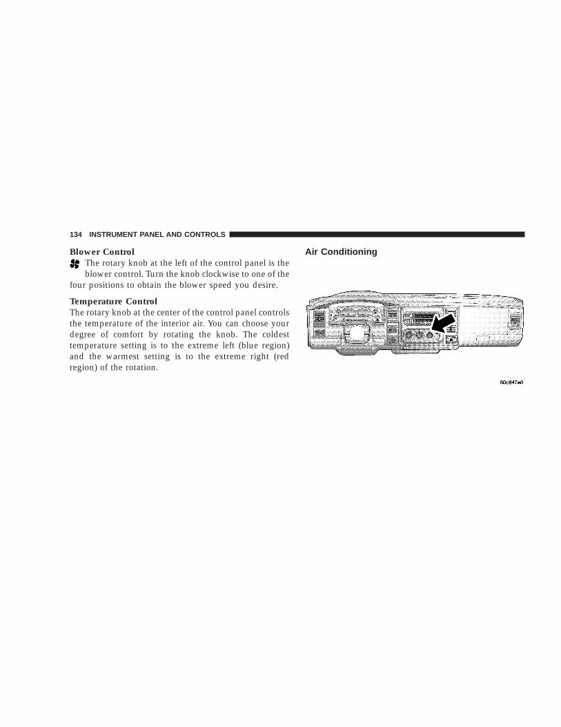
Blower ControlThe rotary knob at the left of the control panel is theblower control. Turn the knob clockwise to one of the
four positions to obtain the blower speed you desire.
Temperature ControlThe rotary knob at the center of the control panel controlsthe temperature of the interior air. You can choose yourdegree of comfort by rotating the knob. The coldesttemperature setting is to the extreme left (blue region)and the warmest setting is to the extreme right (redregion) of the rotation.
Air Conditioning
134 INSTRUMENT PANEL AND CONTROLS

Air Conditioning OperationTo turn on the Air Conditioning, set the fan control at anyspeed and press the snowflake button located at the rightof the control panel. Conditioned air will be directedthrough the outlets selected by the mode control. A lightin the snowflake button shows that the air conditioning ison. Press the button a second time to turn the airconditioning off.
Slight changes in engine speed or power may be noticedwhen the air conditioning compressor is on. This is a
normal occurrence as the compressor will cycle on andoff to maintain comfort and increase fuel economy.
The mode control (at the right of thecontrol panel) can be set in any of thefollowing positions:
NOTE: To improve your selection choices, the systemallows you to operate at intermediate positions betweenthe major modes. These intermediate positions are iden-tified by the small dots.
Recirculation Modes (Panel or Bi-Level )Select the recirculation modes whenthe outside air contains smoke, odors,high humidity, or if rapid cooling isdesired. This feature allows for recir-culation of interior air only. Air flowsthrough the panel outlets in this mode.
INSTRUMENT PANEL AND CONTROLS 135
4

PanelOutside air flows through the outlets located in theinstrument panel.
Bi-LevelOutside air flows through the outlets located in theinstrument panel and at the floor.
FloorOutside air flows primarily through the floor out-lets located under the instrument panel.
MixOutside air flows in equal proportions through thefloor and defroster outlets.
DefrostOutside air is primarily directed to the windshieldthrough the defroster outlets located at the base of
the windshield, and the demister outlets located at theedge of each side of the instrument panel.
Blower ControlThe rotary knob on the left ofthe control panel is theblower control. Turn the knobclockwise to one of the fourpositions to obtain the blowerspeed you desire.
Temperature Control
The rotary knob at the centerof the control panel controlsthe temperature of the inte-rior air. You can choose yourdegree of comfort by rotatingthe knob. The coldest tem-perature setting is to the ex-treme left (blue region) andthe warmest setting is to theextreme right (red region) ofthe rotation.
136 INSTRUMENT PANEL AND CONTROLS

CirculationThe cab is designed with features to promote outside aircirculation. There are grilles in the cab back panel. Theseare air exhausters that provide the means for regularexchange of cab air.
Side window demisters direct air flow specifically to thewindow glass to help prevent interior fogging of theglass. They are located in the extreme outside upperedges of the instrument panel. The demisters also pro-vide extra air ducts for circulation. They are in operationwhenever the Floor, Mix or Defrost modes are in use.
NOTE: When you turn off the engine you may hear ahissing sound from under the hood for a short period oftime. This is a normal condition that occurs if the airconditioning system has been on. It is not an indication ofa problem with the air conditioning system.
Operating Tips
Fast CooldownFor a fast cooldown, turn the blower fan rotary knob tothe extreme right position, turn the mode control to thepanel fresh position, press the snowflake button to turn
on the air conditioning, and drive with the windowsopen for the first few minutes. Once the hot air has beenexpelled, close the windows and turn the mode selectorto the Recirculation Panel Mode or Recirculation ModeBi-level position. When a comfortable condition has beenreached, choose a mode position and adjust the tempera-ture control knob and blower speed as necessary tomaintain comfort. For high humidity conditions it maybe necessary to remain in the Recirculation mode tomaintain comfort.
Window FoggingWindows will fog on the inside when the humidity insidethe vehicle is high. This often occurs in mild or cooltemperatures when it’s rainy or humid. In most casesturning on the Air-conditioning (pressing the snowflakebutton) will clear the fog. Adjust the temperature control,air direction and blower speed to maintain comfort.
As the temperature gets colder it may be necessary todirect air onto the windshield by using MIX Modeposition on the control. Adjust the temperature controland blower speed to maintain comfort. High blower
INSTRUMENT PANEL AND CONTROLS 137
4

speeds will reduce fogging. Interior fogging on thewindshield can be quickly removed by selecting thedefrost mode.
Regular cleaning of the inside of the windows with anon-filming cleaning solution (vinegar and water worksvery well) will help prevent contaminates (cigarettesmoke, perfumes, etc.) from sticking to the windows.Contaminates increase the rate of window fogging.
Summer OperationAir conditioned vehicles must be protected with a highquality antifreeze coolant during summer to provideproper corrosion protection and to raise the boiling pointof the coolant for protection against overheating. A 50 %concentration is recommended.
When using the air conditioner in extremely heavy trafficin hot weather especially when towing a trailer, addi-tional engine cooling may be required. If this situation isencountered, operate the transmission in a lower gear.When stopped in heavy traffic, it may be necessary toshift into NEUTRAL and depress the accelerator slightlyfor fast idle operation.
Winter OperationWhen operating the system during the winter months,make sure the air intake, located directly in front of thewindshield, is free of ice, slush, snow, or other obstruc-tions.
138 INSTRUMENT PANEL AND CONTROLS

Operation Tips Chart
INSTRUMENT PANEL AND CONTROLS 139
4

REAR WINDOW DEFROSTER – Quad-Cab Only
CAUTION!
Use care when washing the inside of the rear win-dow to prevent damage to heating elements. Use asoft cloth and a mild washing solution, wipingparallel to the heating elements. Also, keep allobjects a safe distance from the window to preventdamaging the heating elements.
140 INSTRUMENT PANEL AND CONTROLS

STARTING AND OPERATING
CONTENTS
m Starting Procedures . . . . . . . . . . . . . . . . . . . . 144
▫ Manual Transmission . . . . . . . . . . . . . . . . . . 144
▫ Automatic Transmission . . . . . . . . . . . . . . . . 144
▫ Normal Starting . . . . . . . . . . . . . . . . . . . . . . 144
▫ Engine Block Heater — If Equipped . . . . . . . . 146
m Shifting . . . . . . . . . . . . . . . . . . . . . . . . . . . . . 146
▫ Automatic Transmission . . . . . . . . . . . . . . . . 146
▫ Manual Transmission . . . . . . . . . . . . . . . . . . 150
m Four-Wheel Drive Operation . . . . . . . . . . . . . . 151
▫ NV 233 Transfer Case OperatingInformation/Precautions . . . . . . . . . . . . . . . . 151
▫ Shifting Procedure - NV233 Transfer Case . . . . 155
▫ NV244 Transfer Case OperatingInformation / Precautions . . . . . . . . . . . . . . . 157
▫ Shifting Procedure - NV244 Transfer Case . . . . 160
m Limited-Slip Differential — If Equipped . . . . . 162
m Parking Brake . . . . . . . . . . . . . . . . . . . . . . . . . 163
m Brake System . . . . . . . . . . . . . . . . . . . . . . . . . 164
▫ Rear Wheel Anti-Lock Brake System . . . . . . . . 164
▫ Four-Wheel Anti-Lock Brake System — IfEquipped . . . . . . . . . . . . . . . . . . . . . . . . . . . 165
m Power Steering . . . . . . . . . . . . . . . . . . . . . . . . 166
m Rocking The Vehicle . . . . . . . . . . . . . . . . . . . . 167
m Tire Safety Information . . . . . . . . . . . . . . . . . . 167
5

▫ Tire Markings . . . . . . . . . . . . . . . . . . . . . . . . 167
▫ Tire Identification Number (TIN) . . . . . . . . . . 171
▫ Tire Loading And Tire Pressure . . . . . . . . . . . 172
m Tires—General Information . . . . . . . . . . . . . . . 175
▫ Tire Pressure . . . . . . . . . . . . . . . . . . . . . . . . . 175
▫ Tire Inflation Pressures . . . . . . . . . . . . . . . . . 176
▫ Radial-Ply Tires . . . . . . . . . . . . . . . . . . . . . . 178
▫ Compact Spare Tire — If Equipped . . . . . . . . . 178
▫ Tire Spinning . . . . . . . . . . . . . . . . . . . . . . . . 179
▫ Tread Wear Indicators . . . . . . . . . . . . . . . . . . 180
▫ Replacement Tires . . . . . . . . . . . . . . . . . . . . . 180
▫ Alignment And Balance . . . . . . . . . . . . . . . . . 181
m Supplemental Tire Pressure Information . . . . . 182
m Tire Chains . . . . . . . . . . . . . . . . . . . . . . . . . . . 182
m Snow Tires . . . . . . . . . . . . . . . . . . . . . . . . . . . 183
m Tire Rotation Recommendations . . . . . . . . . . . 183
m Fuel Requirements . . . . . . . . . . . . . . . . . . . . . 184
▫ Reformulated Gasoline . . . . . . . . . . . . . . . . . 184
▫ Gasoline/Oxygenate Blends . . . . . . . . . . . . . . 185
▫ MMT In Gasoline . . . . . . . . . . . . . . . . . . . . . 185
▫ Sulfur In Gasoline . . . . . . . . . . . . . . . . . . . . . 185
▫ Materials Added To Fuel . . . . . . . . . . . . . . . . 186
m Adding Fuel . . . . . . . . . . . . . . . . . . . . . . . . . . 186
▫ Fuel Filler Cap (Gas Cap) . . . . . . . . . . . . . . . 186
▫ Fuel Tank Filler Tube . . . . . . . . . . . . . . . . . . . 187
▫ Fuel System Cautions . . . . . . . . . . . . . . . . . . 188
▫ Carbon Monoxide Warnings . . . . . . . . . . . . . . 189
m Catalytic Converter . . . . . . . . . . . . . . . . . . . . . 189
m Vehicle Loading . . . . . . . . . . . . . . . . . . . . . . . 191
▫ Certification Label . . . . . . . . . . . . . . . . . . . . . 191
▫ Curb Weight . . . . . . . . . . . . . . . . . . . . . . . . . 192
▫ Loading . . . . . . . . . . . . . . . . . . . . . . . . . . . . 192
142 STARTING AND OPERATING

m Loading Wide Building Materials . . . . . . . . . . 194
m Trailer Towing . . . . . . . . . . . . . . . . . . . . . . . . 195
▫ Definitions . . . . . . . . . . . . . . . . . . . . . . . . . . 195
▫ Trailer And Tongue Weight . . . . . . . . . . . . . . 197
▫ Trailer Towing—Hitches . . . . . . . . . . . . . . . . 198
▫ Trailer Towing Information(Maximum Trailer Weight Ratings) . . . . . . . . . 199
▫ Trailer Towing Requirements . . . . . . . . . . . . . 199
▫ Trailer Tow Wiring . . . . . . . . . . . . . . . . . . . . 200
▫ Cooling System Tips—Trailer Towing . . . . . . . 201
m Snowplow . . . . . . . . . . . . . . . . . . . . . . . . . . . 201
▫ Dodge Dakota Models . . . . . . . . . . . . . . . . . . 201
m Recreational Towing (Behind Motorhome, Etc.)Of 4X4 Vehicles . . . . . . . . . . . . . . . . . . . . . . . 202
▫ Recreational Towing Procedure . . . . . . . . . . . . 202
▫ Returning To Normal Operation . . . . . . . . . . . 204
m Traction . . . . . . . . . . . . . . . . . . . . . . . . . . . . . 206
m Equipment Identification Plate . . . . . . . . . . . . 206
STARTING AND OPERATING 143
5

STARTING PROCEDURESThe starter should not be operated for more than 15second intervals. Waiting a few seconds between suchintervals will protect the starter from overheating.
Manual TransmissionApply the parking brake, place the gearshift control leverin NEUTRAL and depress clutch pedal to the floor beforestarting the vehicle. This vehicle is equipped with aclutch interlocking ignition system. It will not start unlessthe clutch is depressed.
Automatic TransmissionStart the engine with the shift lever in NEUTRAL orPARK position. Apply the brake before shifting to anydriving range.
WARNING!
Do not attempt to push or tow your vehicle to get itstarted. Vehicles equipped with an automatic trans-mission cannot be started this way. Unburned fuelcould enter the catalytic converter and once theengine has started, ignite and damage the converterand vehicle. If the vehicle has a discharged battery,booster cables may be used to obtain a start from abooster battery or the battery in another vehicle. Thistype of start can be dangerous if done improperly.See section 6 of this manual for the proper jumpstarting procedures and follow them carefully.
Normal StartingNormal starting of either a warm or cold engine isobtained without pumping or depressing the acceleratorpedal. Turn the key to the START position and releasewhen the engine starts. If the engine fails to start within10 seconds, turn the key to the OFF position, wait 5seconds, then repeat the starting procedure.
144 STARTING AND OPERATING

If Engine Fails To StartIf the engine fails to start after you have followed theNormal Starting procedure, it may be flooded. Push theaccelerator pedal all the way to the floor and hold it therewhile cranking the engine. This should clear any excessfuel in case the engine is flooded.
CAUTION!
To prevent damage to the starter, do not crank theengine for more than 15 seconds at a time. Wait 10 to15 seconds before trying again.
If the engine has been flooded, it may start to run, but nothave enough power to continue running when the key isreleased. If this occurs, continue cranking with the accel-erator pedal pushed all the way to the floor. Release theaccelerator pedal and the key once the engine is runningsmoothly.
If the engine shows no sign of starting after two 15second periods of cranking with the accelerator pedalheld to the floor, the Normal Starting procedure shouldbe repeated.
WARNING!
Never pour fuel or other flammable liquid into thethrottle body air inlet opening in an attempt to startthe vehicle. This could result in flash fire causingserious personal injury.
After StartingThe idle speed is automatically controlled on fuel injectedengines and will decrease as the engine warms up.
STARTING AND OPERATING 145
5

CAUTION!
Long periods of engine idling can cause excessiveexhaust temperatures which can damage your ve-hicle. Do not leave your vehicle unattended with theengine running.
WARNING!
Do not leave children or animals inside parkedvehicles in hot weather. Interior heat build up maycause serious injury or death.
Engine Block Heater — If EquippedThe engine block heater warms engine coolant andpermits quicker starts in cold weather. Connect the cordto a standard 110-115 volt AC electrical outlet with agrounded, three wire extension cord.
The engine block heater cord is located at the right frontof the engine compartment for all engine applications.
WARNING!
Remember to disconnect the cord before driving.Damage to the 110-115 volt electrical cord couldcause electrocution.
SHIFTING
Automatic TransmissionThe gear shift lever is mounted on the right side of thesteering column. To engage a gear for driving, move theshift lever from P-Park or N-Neutral to the desired gearrange (R-Reverse, D-Drive, 2–Second, or 1–First). Tomove the shift lever, pull it toward you, then release itwhen the desired gear range is reached. The Transmis-sion Range Indicator (labeled “Gear Selector”) in theinstrument cluster shows the selected gear range. TheIndicator is illuminated for night driving.
Brake/Transmission Interlock SystemThis system prevents you from moving the gear shift outof Park and into any gear unless the brake pedal ispressed. This system is active only while the ignition
146 STARTING AND OPERATING
switch is in the ON position. Always depress the brakepedal first, before moving the gear selector out of PARK.
Gear RangesDO NOT race the engine when shifting from Park orNeutral position into another gear range.
“P” ParkThis position supplements parking brake by locking thetransmission. The engine can be started in this range.Never use Park while the vehicle is in motion. Apply theparking brake when leaving vehicle in this range. Alwaysapply the parking brake first, then place the selector inthe Park position.
WARNING!
Your vehicle could move and injure you and others ifit is not completely in P (Park). Check by trying tomove the gearshift lever back and forth without firstpulling the lever toward you, after you have set it inP. Make sure it is in Park before leaving the vehicle.
WARNING!
Never use Park position on an automatic transmis-sion as a substitute for the parking brake. Alwaysapply parking brake fully when parked to guardagainst vehicle movement and possible injury ordamage.
WARNING!
It is dangerous to shift the selector lever out of “P” or“N” if the engine speed is higher than idle speed. Ifyour foot is not firmly on the brake pedal, thevehicle could accelerate quickly forward or in re-verse. You could lose control of the vehicle and hitsomeone or something. Only shift into gear whenthe engine is idling normally and when your rightfoot is firmly on the brake pedal.
“R” ReverseUse this range only after the vehicle has come to acomplete stop.
STARTING AND OPERATING 147
5

“N” NeutralShift to Neutral when vehicle is standing for prolongedperiods with engine running. Engine may be started inthis range. Set the parking brake if you must leave thevehicle.
“D” DriveUse this position for most city and highway driving.
“2” SecondUse this position for driving slowly in heavy city trafficor on mountain roads where more precise speed controlis desirable. Use it also when climbing long grades, andfor engine braking when descending moderately steepgrades. To prevent excessive engine speed do not exceed45 mph (72 km/h) in this range.
“1” FirstUse this position for driving up very steep hills and forengine braking at low speeds 25 mph (40 km/h ) or lesswhen going down hill. To prevent excessive engine speeddo not exceed 25 mph (40 km/h) in this range.
OverdriveThe transmission contains a fourth and fifth (if equipped)speed (Overdrive) and will automatically shift fromDrive to Overdrive if the following conditions arepresent:
• The transmission selector is in Drive.
• Engine coolant has reached normal operating tem-perature.
• Vehicle speed is above approximately 30 mph (48km/h).
• The “O/D OFF” button has not been activated.
• Transmission has reached normal operating tempera-ture.
Overdrive can be locked out by pressing the O/D Offbutton located at the end of the transmission gear shiftlever. A light in the instrument cluster shows that thefeature has been deactivated. Pressing the button asecond time restores the Overdrive function.
148 STARTING AND OPERATING

The “O/D OFF” feature must be selected, if desired, eachtime the engine is started.
NOTE: If the vehicle is started in extremely coldtemperatures, the transmission may not shift into Over-drive and will automatically select the most desirablegear for operation at this temperature. Normal operationwill resume when the transmission fluid temperature hasrisen to a suitable level. Refer also to the Note undertorque converter clutch, later in this section.
If the transmission temperature gets extremely hot, thetransmission will automatically select the most desir-able gear for operation at this temperature. If thetransmission temperature becomes hot enough theO/D OFF and/or TRANS TEMP light(s) may illumi-nate and the transmission may downshift out ofOverdrive until the transmission cools down. Aftercooldown, the transmission will resume normal op-eration.
When To Lock Out OverdriveWhen driving in hilly areas, towing a trailer, carrying aheavy load, or whenever frequent transmission shiftingoccurs, press the “O/D OFF” button. This will improveperformance and reduce the potential for transmissionoverheating or failure due to excessive shifting.
Torque Converter ClutchA feature designed to improve fuel economy is includedin all automatic transmissions. A clutch within the torqueconverter engages automatically at a calibrated speed atlight throttle. It engages at higher speeds under heavieracceleration. This may result in a slightly different feelingor response during normal operation in high gear. When
STARTING AND OPERATING 149
5

the vehicle speed drops below a calibrated speed, orduring acceleration, the clutch automatically andsmoothly disengages. The feature is operational in Over-drive and in Drive.
NOTE: The torque converter clutch will not engageuntil the transmission fluid and engine coolant are warm[usually after 1-3 miles (1.6 - 4.8 km) of driving]. Becausethe engine speed is higher when the torque converterclutch is not engaged, it may seem as if the transmissionis not shifting into Overdrive when cold. This is normal.Pressing the O/D OFF button, when the transmission issufficiently warm, will demonstrate that the transmissionis able to shift into and out of overdrive.
NOTE: If the vehicle has not been driven in severaldays, the first few seconds of operation after shifting thetransmission into gear may seem sluggish. This is due tothe fluid partially draining from the torque converter intothe transmission. This condition is normal and will notcause damage to the transmission. The torque converterwill refill within five seconds of shifting from Park intoany other gear position.
Manual Transmission
NOTE: The parking brake should be engaged beforeleaving the vehicle, especially on an incline.
Use each gear in numerical order - donot skip a gear. Be sure the transmissionis in FIRST gear— not THIRD, whenstarting from a standing position; other-wise damage to the clutch can resultfrom starting in THIRD.
For most city driving you will find it easier to use onlythe lower gears. For steady highway driving with lightaccelerations, 5th gear is recommended. To shift into 5thgear, move the shift lever to the right beyond the springpressure point and push it forward. When shifting from5th to 4th gear, pull the lever down toward you in onemotion. Do not pull the lever sharply left as you mayshift accidentally into 2nd gear and damage the trans-mission or engine.
150 STARTING AND OPERATING

To shift into Reverse, come to a complete stop. Depressthe clutch and pause briefly to allow the gear train to spindown. Move the shift lever from the Neutral positionstraight across and back into Reverse.
Never drive with your foot resting on the clutch pedal.Do not attempt to hold the vehicle on a hill with theclutch pedal partially engaged, as this will cause abnor-mal wear on the clutch.
Recommended Shift SpeedsTo use your manual transmission for fuel economy itshould be upshifted as listed below. Shift at the vehiclespeeds listed for acceleration and cruise conditions (rela-tively steady speeds).
Recommended Manual Transmission Shift Speeds inMPH (KM/H)
Engine Model 1 to 2 2 to 3 3 to 4 4 to 53.7L/4.7L All 15 (24) 25 (40) 40 (64) 45 (72)
Higher upshift speeds may be used to obtain a desiredacceleration rate.
DownshiftingMoving from a high gear down to the lower gears indescending numerical order is recommended to preservebrakes when driving down steep hills. In addition,downshifting at the right time provides better accelera-tion when you want to resume speed. For accelerationinitiated at speeds less than 20 mph (30 km/h), secondgear is recommended.
FOUR-WHEEL DRIVE OPERATION
NV 233 Transfer Case OperatingInformation/PrecautionsThe NV233 is an electric shift transfer case and isoperated by the 4WD Control Switch (Transfer CaseSwitch), which is located on the instrument panel.
The NV233 transfer case provides 4 mode positions: 2(rear) wheel drive high range, 4 wheel drive high range,4 wheel drive low range, and neutral.
The NV233 transfer case is designed to be driven in the 2wheel drive position (2WD) for normal street and high-way conditions (dry hard surfaced roads).
STARTING AND OPERATING 151
5

When additional traction is required, the transfer case4HI and 4LO positions can be used to lock the front andrear driveshafts together and force the front and rearwheels to rotate at the same speed. This is accomplishedby rotating the 4WD Control Switch to the desiredposition - see Shifting Procedure section for specificshifting instructions. The 4HI and 4LO positions aredesigned for loose, slippery road surfaces only. Drivingin the 4HI and 4LO positions on dry hard surfaced roadsmay cause increased tire wear and damage to the driv-eline components.
The transfer case Neutral (N) position is selected bydepressing the recessed button located on the lower lefthand corner of the 4WD Control Switch.
NOTE: The transfer case Neutral (N) position is to beused for recreational towing only. See Recreational Tow-ing section for specific procedures on shifting into andout of Neutral (N).
Transfer Case Position Indicator LightsTransfer case position indicator lights are located on theFour-Wheel-Drive Control Switch, found on your instru-ment panel, and indicate the current and desired transfer
case selection. When you select a different transfer caseposition, the indicator lights will do the following:
If All Shift Requirements are Met
1. The current position indicator light will turn OFF.
2. The selected position indicator light will flash until thetransfer case completes the shift.
3. When the shift is complete, the indicator light for theselected position will stop flashing and remain ON.
If One or More Shift Requirements are not Met
1. The indicator light for the current position will remainON.
2. The newly selected position indicator light will flash.
3. The transfer case will not shift.
NOTE: Before retrying a selection, make certain that allthe necessary requirements for selecting a new transfercase position have been met. To retry the selection, turnthe control knob back to the current position, wait five (5)
152 STARTING AND OPERATING
seconds, and retry selection. To find the shift require-ments, refer to the 9Shifting Procedure9 for your transfercase, located in this section of the owner’s manual.
The “SERVICE 4WD” warning light monitors the electricshift 4WD system. If this light remains on after enginestart up or illuminates during driving, it means that the4WD system is not functioning properly and that serviceis required.
WARNING!
Always engage the parking brake when poweringdown the vehicle if the (Service 4WD( light isilluminated. Not engaging the parking brake mayallow the vehicle to roll which may cause personalinjury.
NOTE: Do not attempt to make a shift while only thefront or rear wheels are spinning. The NV233 transfercase is not equipped with a synchronizer and thereforethe front and rear driveshaft speeds must be equal for theshift to take place. Shifting while only the front or rearwheels are spinning can cause damage to the transfercase.
When operating your vehicle in 4LO, the engine speed isapproximately three times that of the 2WD or 4HIpositions at a given road speed. Take care not to over-speed the engine and do not exceed 25 mph (40 km/h).
Proper operation of 4 wheel drive vehicles depends ontires of equal size, type and circumference on each wheel.Any difference in tire size can cause damage to thetransfer case.
Because 4 wheel drive provides improved traction, thereis a tendency to exceed safe turning and stopping speeds.Do not go faster than road conditions permit.
STARTING AND OPERATING 153
5

WARNING!
You or others could be injured if you leave thevehicle unattended with the transfer case in theNeutral (N) position without first fully engaging theparking brake. The transfer case Neutral (N) positiondisengages both the front and rear driveshafts fromthe powertrain and will allow the vehicle to moveregardless of the transmission position. The parkingbrake should always be applied when the driver isnot in the vehicle.
For additional information on the appropriate use of eachtransfer case mode position see the information below:
2WDRear Wheel Drive High Range - Normal street andhighway driving. Dry hard surfaced roads.
4HI4 Wheel Drive High Range - Locks the front and reardriveshafts together. Forces the front and rear wheels torotate at the same speed. Additional traction for loose,slippery road surfaces only.
4LO4 Wheel Drive Low Range - Low speed 4 wheel drive.Locks the front and rear driveshafts together. Forces thefront and rear wheels to rotate at the same speed.Additional traction and maximum pulling power forloose, slippery road surfaces only. Do not exceed 25 mph(40 km/h).
NNeutral - Disengages both the front and rear driveshaftsfrom the powertrain. To be used for flat towing behindanother vehicle. See Recreational Towing for more infor-mation.
154 STARTING AND OPERATING

Shifting Procedure - NV233 Transfer Case
NOTE: If any of the requirements to select a newtransfer case position have not been met, the transfer casewill not shift.The indicator light for the previous positionwill remain ON and the newly selected position indicatorlight will continue to flash until all the requirements forthe selected position have been met. To retry a shift:return the control knob back to the original position,make certain all shift requirements have been met, waitfive (5) seconds and try the shift again.
2WD to 4HI or 4HI to 2WDRotate the 4WD Control Switch to the desired position.Shifts between 2WD and 4HI can be done with thevehicle stopped or in motion. With the vehicle in motion,the transfer case will engage / disengage faster if youmomentarily release the accelerator pedal after turningthe control switch. If the vehicle is stopped, the ignitionkey must be in the ON position with the engine eitherRUNNING or OFF. This shift cannot be completed if thekey is in the accessory position.
NOTE: On vehicles equipped with Anti-Lock BrakeSystems, the 4x4 system will not allow shifts between2WD/ 4HI if the rear wheels are spinning (no traction). Inthis situation the selected position indicator light willflash and the original position indicator light will remainON. At this time, reduce speed and stop spinning thewheels to complete the shift. There may be a delay up to10 seconds for the shift to complete after the wheels havestopped spinning.
STARTING AND OPERATING 155
5

4HI to 4LO or 4LO to 4HI
NOTE: When shifting into or out of 4LO some gearnoise may be heard. This noise is normal and is notdetrimental to the vehicle or occupants.
Shifting can be performed with the vehicle rolling 2-3mph (3-5 km/h) or completely stopped. USE EITHER OFTHE FOLLOWING PROCEDURES:
Preferred Procedure
1. With engine RUNNING, slow vehicle to 2-3 mph (3-5km/h).
2. Shift the transmission into NEUTRAL (depress clutchon manual transmissions).
3. While still rolling, rotate the transfer case controlswitch to the desired position.
4. After the desired position indicator light is ON (notflashing), shift transmission back into gear (release clutchon manual transmissions).
Alternate Procedure
1. Bring the vehicle to complete stop.
2. With the key ON and the engine either OFF orRUNNING, shift the transmission into NEUTRAL (de-press clutch on manual transmissions).
3. Rotate the transfer case control switch to the desiredposition.
4. After the desired position indicator light is ON (notflashing), shift transmission back into gear (release clutchon manual transmissions).
NOTE: If steps 1 or 2 of either the Preferred or AlternateProcedure are not satisfied prior to attempting the shift orif they no longer are being met while the shift attempt isin process then the desired position indicator light willflash continuously while the original position indicatorlight is ON, until all requirements have been met.
NOTE: The ignition key must be ON for a shift to takeplace and for the position indicator lights to be operable.If the key is not ON then the shift will not take place andno position indicator lights will be on or flashing.
156 STARTING AND OPERATING

NV244 Transfer Case Operating Information /PrecautionsThe NV244 is an electric shift transfer case and isoperated by the 4WD Control Switch, which is located onthe instrument panel.
The NV244 transfer case provides 4 mode positions -Normal all wheel drive high range, 4 wheel drive highrange, 4 wheel drive low range, and neutral.
This transfer case is equipped with an inter-axle differ-ential that allows driving the vehicle in the normal allwheel drive position (AWD) at all times on any givenroad surface, including dry hard surfaced roads. TheAWD mode allows the front and rear wheels to rotate atdifferent speeds. This eliminates driveline binding andcomponent wear normally associated with driving thevehicle in the 4HI position on dry hard surfaced roads.This feature provides the safety, security, and conve-nience of operating in all wheel drive at all timesregardless of road conditions.
When additional traction is required, the 4HI and 4LOpositions can be used to lock the front and rear drive-shafts together through the transfer case inter-axle differ-ential and force the front and rear wheels to rotate at thesame speed. This is accomplished by rotating the 4WDControl Switch to these positions. The 4HI and 4LOpositions are intended for loose, slippery road surfacesonly. Driving in the 4HI and 4LO positions on dry hardsurfaced roads may cause increased tire wear and dam-age to the driveline components.
The transfer case Neutral (N) position is selected bydepressing the recessed button located on the lower lefthand corner of the 4WD Control Switch.
NOTE: The transfer case Neutral (N) position is to beused for recreational towing only. (See Recreational Tow-ing section for specific procedures on shifting into andout of Neutral (N).
Transfer Case Position Indicator LightsTransfer case position indicator lights are located on theFour-Wheel-Drive Control Switch, found on your instru-ment panel, and indicate the current and desired transfer
STARTING AND OPERATING 157
5

case selection. When you select a different transfer caseposition, the indicator lights will do the following:
If All Shift Requirements are Met
1. The current position indicator light will turn OFF.
2. The selected position indicator light will flash until thetransfer case completes the shift.
3. When the shift is complete, the indicator light for theselected position will stop flashing and remain ON.
If One or More Shift Requirements are not Met
1. The indicator light for the current position will remainON.
2. The newly selected position indicator light will flash.
3. The transfer case will not shift.
NOTE: Before retrying a selection, make certain that allthe necessary requirements for selecting a new transfercase position have been met. To retry the selection, turnthe control knob back to the current position, wait five (5)
seconds, and retry selection. To find the shift require-ments, refer to the 9Shifting Procedure9 for your transfercase, located in this section of the owner’s manual.
The SERVICE 4WD warning light monitors the electricshift 4WD system. If this light remains on after enginestart up or illuminates during driving, it means that the4WD system is not functioning properly and that serviceis required.
WARNING!
Always engage the parking brake when poweringdown the vehicle if the (Service 4WD( light isilluminated. Not engaging the parking brake mayallow the vehicle to roll which may cause personalinjury.
NOTE: Do not attempt to make a shift while only thefront or rear wheels are spinning. The NV244 transfercase is not equipped with a synchronizer and thereforethe front and rear driveshaft speeds must be equal for the
158 STARTING AND OPERATING
shift to take place. Shifting while only the front or rearwheels are spinning can cause damage to the transfercase.
When operating your vehicle in 4LO, the engine speed isapproximately three times that of the AWD or 4HIpositions at a given road speed. Take care not to over-speed the engine and do not exceed 25 mph (40 km/h).
Proper operation of 4 wheel drive vehicles depends ontires of equal size, type and circumference on each wheel.Any difference in tire size can cause damage to thetransfer case.
Because 4 wheel drive provides improved traction, thereis a tendency to exceed safe turning and stopping speeds.Do not go faster than road conditions permit.
WARNING!
You or others could be injured if you leave thevehicle unattended with the transfer case in theNeutral (N) position without first fully engaging theparking brake. The transfer case Neutral (N) positiondisengages both the front and rear driveshafts fromthe powertrain and will allow the vehicle to moveregardless of the transmission position. The parkingbrake should always be applied when the driver isnot in the vehicle.
For additional information on the appropriate use of eachtransfer case mode position see the information below:
AWDNormal All Wheel Drive High Range - Employs inter-axle differential. Allows front and rear wheels to rotate atdifferent speeds. All road surfaces.
STARTING AND OPERATING 159
5

4HI4 Wheel Drive High Range - Locks the transfer caseinter-axle differential. Forces front and rear wheels torotate at the same speed. Additional traction for loose,slippery road surfaces only.
4LO4 Wheel Drive Low Range - Low speed 4 wheel drive.Locks the transfer case inter-axle differential. Forces thefront and rear wheels to rotate at the same speed.Additional traction and maximum pulling power forloose, slippery road surfaces only. Do not exceed 25 mph(40 km/h).
NNeutral - Disengages both the front and rear driveshaftsfrom the powertrain. To be used for flat towing behindanother vehicle. See Recreational Towing for more infor-mation.
Shifting Procedure - NV244 Transfer Case
NOTE: If any of the requirements to select a newtransfer case position have not been met, the transfer casewill not shift.The indicator light for the previous positionwill remain ON and the newly selected position indicatorlight will continue to flash until all the requirements forthe selected position have been met. To retry a shift:return the control knob back to the original position,make certain all shift requirements have been met, waitfive (5) seconds and try the shift again.
160 STARTING AND OPERATING

AWD to 4HI or 4HI to AWDRotate the 4WD Control Switch to the desired position.Shifts between AWD and 4HI can be done with thevehicle stopped or in motion. With the vehicle in motion,the transfer case will engage / disengage faster if youmomentarily release the accelerator pedal after turningthe control switch. If the vehicle is stopped the ignitionkey must be in the ON position with the engine eitherRUNNING or OFF. This shift cannot be completed if thekey is in the accessory position.
NOTE: On vehicles equipped with a Anti-Lock BrakeSystems, the 4x4 system will not allow shifts betweenAWD/ 4HI if the rear wheels are spinning (no traction).In this situation the selected position indicator light willflash and the original position indicator light will remainON. At this time, reduce speed and stop spinning thewheels to complete the shift. There may be a delay up to10 seconds for the shift to complete after the wheels havestopped spinning.
NOTE: Delayed shifting out of the 4HI position may beexperienced due to uneven tire wear, low tire pressure, orexcessive loading.
4HI to 4LO or 4LO to 4HI
NOTE: When shifting into or out of 4LO some gearnoise may be heard. This noise is normal and is notdetrimental to the vehicle or occupants.
Shifting can be performed with the vehicle rolling 2-3mph (3-5 km/h) or completely stopped. USE EITHER OFTHE FOLLOWING PROCEDURES:
Preferred Procedure
1. With engine RUNNING, slow vehicle to 2-3 mph (3-5km/h).
2. Shift the transmission into NEUTRAL (depress clutchon manual transmissions).
3. Ensure ignition key is in the ON position with theengine either RUNNING or OFF. While still rolling,rotate the transfer case control switch to the desiredposition.
4. After the desired position indicator light is ON (notflashing), shift transmission back into gear (release clutchon manual transmissions).
STARTING AND OPERATING 161
5

Alternate Procedure
1. Bring the vehicle to complete stop.
2. With the key ON and the engine either OFF orRUNNING, shift the transmission into NEUTRAL (de-press clutch on manual transmissions).
3. Rotate the transfer case control switch to the desiredposition.
4. After the desired position indicator light is ON (notflashing), shift transmission back into gear (release clutchon manual transmissions).
NOTE: If steps 1 or 2 of either the Preferred or AlternateProcedure are not satisfied prior to attempting the shift orif they no longer are being met while the shift attempt isin process, then the desired position indicator light willflash continuously while the original position indicatorlight is ON, until all requirements have been met.
NOTE: The ignition key must be ON for a shift to takeplace and for the position indicator lights to be operable.If the key is not ON then the shift will not take place andno position indicator lights will be on or flashing.
LIMITED-SLIP DIFFERENTIAL — IF EQUIPPEDThe limited-slip differential provides additional tractionon snow, ice, mud, sand and gravel. It improves tractionwhen there is a difference between the characteristics ofthe surface under the right and left rear wheels. Duringnormal driving and cornering, the limited-slip unit issimilar to a conventional differential. But on a slipperysurface, the differential delivers more of the driving effortto the wheel having the better traction.
WARNING!
On vehicles equipped with a limited-slip differen-tial, never run the engine with one rear wheel off theground. The vehicle may drive through the rearwheel remaining on the ground and cause you tolose control of the vehicle.
Care should be taken to avoid sudden accelerations whenboth rear wheels are on a slippery surface. This couldcause both rear wheels to spin, and allow the vehicle toslide sideways on the crowned surface of a road or in aturn.
162 STARTING AND OPERATING

PARKING BRAKEThe parking brake should be applied whenever thedriver is not in the vehicle.
The foot operated parking brake is positioned below thelower left corner of the instrument panel.
To apply the parking brake: Place your foot on theparking brake pedal and push firmly downward as far asthe pedal will go. When the parking brake is applied andthe ignition is ON, the BRAKE light in the instrumentcluster will light.
NOTE: The BRAKE light in the instrument clusterindicates only that the parking brake is applied—it doesnot indicate the degree of application.
To release the parking brake: Pull the parking brakerelease handle towards you. The BRAKE light in theinstrument cluster will go out when the parking brake isdisengaged.
To park on a hill: You must make sure that the parkingbrake is fully applied and the gear shift lever is in PARK(for an automatic transmission) or in REVERSE or FIRST(for a manual transmission). You should apply the park-ing brake before shifting to PARK; otherwise, the load onthe transmission locking mechanism may make it diffi-cult to move the shift lever out of the Park position.
When parking on a hill, turn the front wheels:
• Toward the curb on a downhill grade.
• Away from the curb on an uphill grade.
STARTING AND OPERATING 163
5

WARNING!
• Always fully apply the parking brake when leav-ing your vehicle, or vehicle may roll and causedamage or injury. Also be certain to leave anautomatic transmission in Park, a manual trans-mission in Reverse or first gear. Failure to do somay cause the vehicle to roll and cause damage orinjury.
• Be sure the parking brake is fully disengagedbefore driving. Failure to do so can lead to brakefailure and an accident.
• Leaving children in a vehicle unattended is dan-gerous for a number of reasons. A child or otherscould be injured. Children should be warned notto touch the parking brake or the gear selectorlever. Don’t leave the key in the ignition. A childcould operate power windows, other controls, ormove the vehicle.
BRAKE SYSTEMIn the event power assist is lost for any reason (forexample, repeated brake applications with the engineoff), the brakes will still function. The effort required tobrake the vehicle will be significantly increased over thatrequired with the power system operating.
If either the front or rear hydraulic system loses normalcapability, the remaining system will still function withsome loss of braking effectiveness. This will be evident byincreased pedal travel during application, greater pedalforce required to slow or stop, and activation of the BrakeWarning light and the ABS light during brake use.
Rear Wheel Anti-Lock Brake SystemThis Anti-Lock Brake System provides increased vehiclestability and brake performance under most brakingconditions. The system automatically controls the opera-tion of the rear brakes to prevent rear wheel lockup.
The system remains operational in the four-wheel drivemode. The level of performance is reduced when thefront brakes are locked up. This will cause the rear brakesto lock-up through the drivetrain, which may reduce theeffectiveness of the anti-lock system.
164 STARTING AND OPERATING
During severe braking conditions, particularly withchanging road surfaces, such as ice to concrete, a slightdrop or minor pulsation may be felt in the brake pedal.
WARNING!
Both Anti-Lock Brake Systems contain sophisticatedelectronic equipment. It may be susceptible to inter-ference caused by improperly installed or high out-put radio transmitting equipment. This interferencecan cause possible loss of anti-lock braking capabil-ity. Installation of such equipment should be doneby qualified professionals.
Four-Wheel Anti-Lock Brake System — IfEquippedThis Anti-Lock Brake System is designed to aid the driverin maintaining vehicle control under adverse brakingconditions. The system operates with a separate com-puter to modulate hydraulic pressure to prevent wheellock-up and help avoid skidding on slippery surfaces.
The system’s pump motor runs during an ABS stop toprovide regulated hydraulic pressure. The pump motormakes a low humming noise during operation, which isnormal.
The Anti-Lock Brake System includes an amber ABSwarning light. When the light is illuminated, the Anti-Lock Brake System is not functioning. The system revertsto standard non-anti-lock brakes. Turning the ignitionOFF and ON again may reset the Anti-Lock Brake Systemif the fault detected was only momentary.
WARNING!
Pumping of the Anti-Lock Brakes will diminishtheir effectiveness and may lead to an accident.Pumping makes the stopping distance longer. Justpress firmly on your brake pedal when you need toslow down or stop.
STARTING AND OPERATING 165
5

WARNING!
• Anti-lock system (ABS) cannot prevent the natu-ral laws of physics from acting on the vehicle, norcan it increase braking or steering efficiency be-yond that afforded by the condition of the vehiclebrakes and tires or the traction afforded.
• The ABS cannot prevent accidents, includingthose resulting from excessive speed in turns,following another vehicle too closely, or hydro-planing. Only a safe, attentive, and skillful drivercan prevent accidents.
• The capabilities of an ABS equipped vehicle mustnever be exploited in a reckless or dangerousmanner which could jeopardize the user’s safetyor the safety of others.
When you are in a severe braking condition involvinguse of the Anti-lock Brake System, you will experiencesome pedal drop as the vehicle comes to a stop. This isthe result of the system reverting to the base brakesystem.
Engagement of the Anti-lock Brake System may beaccompanied by a pulsing sensation. You may also hear aclicking noise. These occurrences are normal, and indi-cate that the system is functioning properly.
POWER STEERINGYour power steering system will provide mechanicalsteering capability if power assist is lost.
If for any reason the hydraulic pressure is interrupted, itwill still be possible to steer your vehicle. Under theseconditions you will experience an increase in steeringeffort and a noticeable amount of “free play” in thesteering wheel.
166 STARTING AND OPERATING

ROCKING THE VEHICLEIf vehicle becomes stuck in snow, sand, or mud, it canoften be moved by a rocking motion. Move the gearselector rhythmically between FIRST and REVERSE,while applying slight pressure to the accelerator.
The least amount of accelerator pedal pressure to main-tain the rocking motion without spinning the wheels orracing the engine is most effective. Allow the engine toidle with the transmission selector in NEUTRAL for atleast one minute after every five rocking-motion cycles.This will minimize overheating and reduce the risk oftransmission failure during prolonged efforts to free astuck vehicle.
TIRE SAFETY INFORMATION
Tire Markings
STARTING AND OPERATING 167
5

NOTE:• P(Passenger)-Metric tire sizing is based on U.S. design
standards. P-Metric tires have the letter “P” moldedinto the sidewall preceding the size designation. Ex-ample: P215/65R15 95H.
• European Metric tire sizing is based on Europeandesign standards. Tires designed to this standard havethe tire size molded into the sidewall beginning withthe section width. The letter 9P9 is absent from this tiresize designation. Example: 215/65R15 96H
• LT(Light Truck)-Metric tire sizing is based on U.S.design standards. The size designation for LT-Metrictires is the same as for P-Metric tires except for theletters “LT” that are molded into the sidewall preced-ing the size designation. Example: LT235/85R16.
• Temporary Spare tires are high pressure compactspares designed for temporary emergency use only.Tires designed to this standard have the letter “T”molded into the sidewall preceding the size designa-tion. Example: T145/80D18 103M.
• High Flotation tire sizing is based on U.S. designstandards and begins with the tire diameter moldedinto the sidewall. Example: 31x10.5 R15 LT.
168 STARTING AND OPERATING

Tire Sizing Chart
EXAMPLE:Size Designation:
P = Passenger car tire size based on U.S. design standards(....blank....( = Passenger car tire based on European design standardsLT = Light Truck tire based on U.S. design standardsT = Temporary Spare tire31 = Overall Diameter in Inches (in)215 = Section Width in Milimeters (mm)65 = Aspect Ratio in Percent (%)
—Ratio of section height to section width of tire.10.5 = Section Width in Inches (in)R = Construction Code
—9R9 means Radial Construction.—9D9 means Diagonal or Bias Construction.
15 = Rim Diameter in Inches (in)
STARTING AND OPERATING 169
5

EXAMPLE:Service Description:
95 = Load Index—A numerical code associated with the maximum load a tire can carry.
H = Speed Symbol—A symbol indicating the range of speeds at which a tire can carry a load correspondingto its load index under certain operating conditions.—The maximum speed corresponding to the Speed Symbol should only be achieved un-der specified operating conditions. (ie. tire pressure, vehicle loading, road conditions andposted speed limits).
Load Identification:(....blank....( = Absence of any text on sidewall of the tire indicates a Standard Load (SL) TireExtra Load (XL) = Extra Load (or Reinforced) TireLight Load = Light Load TireC,D,E = Load range associated with the maximum load a tire can carry at a specified pressure
Maximum Load — Maximum Load indicates the maximum load this tire is designed to carry.Maximum Pressure — Maximum Pressure indicates the maximum permissible cold tire inflation pressure for thistire.
170 STARTING AND OPERATING

Tire Identification Number (TIN)The TIN may be found on one or both sides of the tirehowever the date code may only be on one side. Tireswith white sidewalls will have the full TIN includingdate code located on the white sidewall side of the tire.
Look for the TIN on the outboard side of black sidewalltires as mounted on the vehicle. If the TIN is not found onthe outboard side then you will find it on the inboard sideof the tire.
EXAMPLE:DOT MA L9 ABCD 0301
DOT = Department of Transportation—This symbol certifies that the tire is in compliance with the U.S. Department of Transportation tiresafety standards, and is approved for highway use.
MA = Code representing the tire manufacturing location.(2 digits)L9 = Code representing the tire size.(2 digits)ABCD = Code used by tire manufacturer.(1 to 4 digits)03 = Number representing the week in which the tire was manufactured.(2 digits)
—03 means the 3rd week.01 = Number representing the year in which the tire was manufactured.(2 digits)
—01 means the year 2001.—Prior to July 2000, tire manufacturers were only required to have 1 number to represent the year inwhich the tire was manufactured. Example: 031 could represent the 3rd week of 1981 or 1991.
STARTING AND OPERATING 171
5

Tire Loading and Tire Pressure
Tire Placard Location
NOTE: Some vehicles have a “Tire and Loading Infor-mation” placard located on the driver’s side “B” pillar.
Tire and Loading Information Placard
This placard tells you important information about the,1) number of people that can be carried in the vehicle2) the total weight your vehicle can carry3) the tire size designed for your vehicle4) the cold tire inflation pressures for the front, rearand spare tires.
LoadingThe vehicle maximum load on the tire must not exceedthe load carrying capacity of the tire on your vehicle. Youwill not exceed the tire’s load carrying capacity if you
172 STARTING AND OPERATING

adhere to the loading conditions, tire size and cold tireinflation pressures specified on the Tire and LoadingInformation placard and the Vehicle Loading section ofthis manual.
NOTE: Under a maximum loaded vehicle condition,gross axle weight ratings (GAWR’s) for the front and rearaxles must not be exceeded. For further information onGAWR’s, vehicle loading and trailer towing, see theVehicle Loading section of this manual.
To determine the maximum loading conditions of yourvehicle, locate the statement “The combined weight ofoccupants and cargo should never exceed XXX kg or XXXlbs.” on the Tire and Loading Information placard. Thecombined weight of occupants, cargo/luggage andtrailer tongue weight (if applicable) should never exceedthe weight referenced here.
Steps for Determining Correct Load Limit
1. Locate the statement “The combined weight of occu-pants and cargo should never exceed XXX pounds” onyour vehicle’s placard.
2. Determine the combined weight of the driver andpassengers that will be riding in your vehicle.
3. Subtract the combined weight of the driver and pas-sengers from XXX kilograms or XXX pounds.
4. The resulting figure equals the available amount of cargoand luggage load capacity. For example, if “XXX” amountequals 1400 lbs. and there will be five 150 lb. passengers inyour vehicle, the amount of available cargo and luggageload capacity is 650 lb. (1400–750 (5 x 150) = 650 lb.)
5. Determine the combined weight of luggage and cargobeing loaded on the vehicle. That weight may not safelyexceed the available cargo and luggage load capacitycalculated in step 4.
6. If your vehicle will be towing a trailer, load from yourtrailer will be transferred to your vehicle. Consult thismanual to determine how this reduces the availablecargo and luggage load capacity of your vehicle.
NOTE: The following table shows examples on how tocalculate total load, cargo/luggage and towing capacitiesof your vehicle with varying seating configurations andnumber and size of occupants. This table is for illustra-tion purposes only and may not be accurate for theseating and load carry capacity of your vehicle.
STARTING AND OPERATING 173
5

NOTE: For the following example the combined weight ofoccupants and cargo should never exceed 865 lbs. (392 Kg).
174 STARTING AND OPERATING
WARNING!
Overloading of your tire is dangerous. Overloadingcan cause tire failure, affect vehicle handling, andincrease your stopping distance. Use tires of therecommended load capacity for your vehicle. Neveroverload them.
TIRES—GENERAL INFORMATION
Tire PressureProper tire inflation pressure is essential to the safe andsatisfactory operation of your vehicle. Three primaryareas are affected by improper tire pressure:
1. Safety—
WARNING!
Improperly inflated tires are dangerous and cancause accidents.
• Under inflation increases tire flexing and canresult in tire failure.
• Over inflation reduces a tire’s ability to cushionshock. Objects on the road and chuck holes can causedamage that results in tire failure.
• Unequal tire pressures can cause steering prob-lems. You could lose control of your vehicle.
• Over inflated or under inflated tires can affectvehicle handling and can fail suddenly, resulting inloss of vehicle control.
• Unequal tire pressures from one side of the vehicleto the other can cause the vehicle to drift to the rightor left.
Always drive with each tire inflated to the recom-mended cold tire inflation pressure.
STARTING AND OPERATING 175
5

2. Economy—Improper inflation pressures can cause uneven wearpatterns to develop across the tire tread. These abnormalwear patterns will reduce tread life resulting in a need forearlier tire replacement. Underinflation also increases tirerolling resistance and results in higher fuel consumption.
3. Ride Comfort and Vehicle Stability—Proper tire inflation contributes to a comfortable ride.Overinflation produces a jarring and uncomfortable ride.
Tire Inflation PressuresThe proper cold tire inflation pressure for passenger carsis listed on either the face of the driver’s door or thedriver’s side “B” pillar. For vehicles other than passengercars, the cold tire inflation pressures are listed on eitherthe “B” pillar, the Certification Label or in the TireInflation Pressures brochure in the glove compartment.
Some vehicles may have Supplemental Tire PressureInformation for vehicle loads that are less that the maxi-mum loaded vehicle condition. These pressure condi-tions will be found in the “Supplemental Tire PressureInformation” section of this manual.
The pressure should be checked and adjusted as well asinspecting for signs of tire wear or visible damage at leastonce a month. Use a good quality pocket-type gauge tocheck tire pressure. Do not make a visual judgementwhen determining proper inflation. Radial tires may lookproperly inflated even when they are underinflated.
“B” PILLAR
176 STARTING AND OPERATING

CAUTION!
After inspecting or adjusting the tire pressure al-ways reinstall the valve stem cap–if equipped. Thiswill prevent moisture and dirt from entering thevalve stem, which could damage the valve stem.
Inflation pressures specified on the placard are always“cold tire inflation pressure”. Cold tire inflation pressureis defined as the tire pressure after the vehicle has notbeen driven for at least 3 hours, or driven less than 1mile(1 km) after a 3 hour period. The cold tire inflationpressure must not exceed the maximum inflation pres-sure molded into the tire side wall.
Check tire pressures more often if subject to a wide rangeof outdoor temperatures, as tire pressures vary withtemperature changes.
Tire pressures change by approximately 1 psi (7 kPa) per12° F (7° C) of air temperature change. Keep this in mindwhen checking tire pressure inside a garage especially inthe winter.
Example: If garage temperature = 68° F (20° C) and theoutside temperature = 32° F (0° C) then the cold tireinflation pressure should be increased by 3 psi (21 kPa),which equals 1 psi (7 kPa) for every 12° F (7° C) for thisoutside temperature condition.
Tire pressure may increase from 2 to 6 psi (13 to 40 kPa)during operation. DO NOT reduce this normal pressurebuild up or your tire pressure will be too low.
Tire Pressures for High Speed OperationThe manufacturer advocates driving at safe speedswithin posted speed limits. Where speed limits or condi-tions are such that the vehicle can be driven at highspeeds, maintaining correct tire inflation pressure is veryimportant. Increased tire pressure and reduced vehicleloading may be required for high speed vehicle opera-tion. Refer to original equipment or an authorized tiredealer for recommended safe operating speeds, loadingand cold tire inflation pressures.
STARTING AND OPERATING 177
5

WARNING!
High speed driving with your vehicle under maxi-mum load is dangerous. The added strain on yourtires could cause them to fail. You could have aserious accident. Don’t drive a vehicle loaded to themaximum capacity at continuous speeds above 75mph (120 km/h).
Radial-Ply Tires
WARNING!
Combining radial ply tires with other types of tireson your vehicle will cause your vehicle to handlepoorly. The instability could cause an accident. Al-ways use radial ply tires in sets of four (or 6, in caseof trucks with dual rear wheels). Never combinethem with other types of tires.
Cuts and punctures in radial tires are repairable only inthe tread area because of sidewall flexing. Consult yourauthorized tire dealer for radial tire repairs.
Compact Spare Tire — If EquippedThe compact spare is for temporary emergency use withradial tires. It is engineered to be used on your stylevehicle only. Since this tire has limited tread life, theoriginal tire should be repaired (or replaced) and rein-stalled at the first opportunity.
WARNING!
Temporary use spare tires are for emergency useonly. With these tires, do not drive more than 50 mph(80 km/h). Temporary-use spare tires have a totaltread life of 3,000 miles (4 800 km). Be sure to followthe warnings which apply to your spare. Failure todo so could result in spare tire failure and loss ofvehicle control.
178 STARTING AND OPERATING

Do not install a wheel cover or attempt to mount aconventional tire on the compact spare wheel, since thewheel is designed specifically for the compact spare.
Do not install more than one compact spare tire/wheelon the vehicle at any given time.
CAUTION!
Because of the reduced ground clearance, do not takeyour vehicle through an automatic car wash with thecompact spare installed. Damage to the vehicle mayresult.
Tire SpinningWhen stuck in mud, sand, snow, or ice conditions, do notspin your vehicle’s wheels above 35 mph (55 km/h).
See the paragraph on Freeing A Stuck Vehicle in Section6 of this manual.
WARNING!
Fast spinning tires can be dangerous. Forces gener-ated by excessive wheel speeds may cause tire dam-age or failure. A tire could explode and injuresomeone. Do not spin your vehicle’s wheels fasterthan 35 mph (55 km/h) when you are stuck. Anddon’t let anyone near a spinning wheel, no matterwhat the speed.
STARTING AND OPERATING 179
5
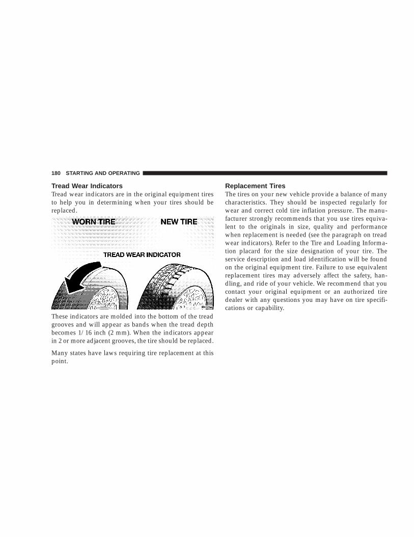
Tread Wear IndicatorsTread wear indicators are in the original equipment tiresto help you in determining when your tires should bereplaced.
These indicators are molded into the bottom of the treadgrooves and will appear as bands when the tread depthbecomes 1/16 inch (2 mm). When the indicators appearin 2 or more adjacent grooves, the tire should be replaced.
Many states have laws requiring tire replacement at thispoint.
Replacement TiresThe tires on your new vehicle provide a balance of manycharacteristics. They should be inspected regularly forwear and correct cold tire inflation pressure. The manu-facturer strongly recommends that you use tires equiva-lent to the originals in size, quality and performancewhen replacement is needed (see the paragraph on treadwear indicators). Refer to the Tire and Loading Informa-tion placard for the size designation of your tire. Theservice description and load identification will be foundon the original equipment tire. Failure to use equivalentreplacement tires may adversely affect the safety, han-dling, and ride of your vehicle. We recommend that youcontact your original equipment or an authorized tiredealer with any questions you may have on tire specifi-cations or capability.
180 STARTING AND OPERATING

WARNING!
• Do not use a tire, wheel size or rating other thanthat specified for your vehicle. Some combina-tions of unapproved tires and wheels may changesuspension dimensions and performance charac-teristics, resulting in changes to steering, han-dling, and braking of your vehicle. This can causeunpredictable handling and stress to steering andsuspension components. You could lose controland have an accident resulting in serious injury ordeath. Use only the tire and wheel sizes with loadratings approved for your vehicle.
• Never use a tire with a smaller load index orcapacity, other than what was originally equippedon your vehicle. Using a tire with a smaller loadindex could result in tire overloading and failure.You could lose control and have an accident.
• Failure to equip your vehicle with tires havingadequate speed capability can result in suddentire failure and loss of vehicle control.
CAUTION!
Replacing original tires with tires of a different sizemay result in false speedometer and odometer read-ings.
Alignment And BalancePoor suspension alignment may result in:
• Fast tire wear.
• Uneven tire wear, such as feathering and one-sidedwear.
• Vehicle pull to right or left.
Tires may also cause the vehicle to pull to the left or right.Alignment will not correct this condition. See your dealerfor proper diagnosis.
Improper alignment will not cause vehicle vibration.Vibration may be a result of tire and wheel out-of-balance. Proper balancing will reduce vibration andavoid tire cupping and spotty wear.
STARTING AND OPERATING 181
5

SUPPLEMENTAL TIRE PRESSURE INFORMATIONA light load vehicle condition is defined as two passen-gers {150 lbs (68 kg) each} plus 200 lbs (91kg) of cargo.Cold tire inflation pressures for a lightly loaded vehiclewill be found on a “Supplemental Tire Pressure Inflation”label located on the face of the driver’s door or in the TireInformation Pressures pamphlet in the glove box.
TIRE CHAINSUse only Class S chains, or other traction aids that meetSAE specifications. Chains must be the proper size for thevehicle as recommended by the chain manufacturer.
These cautions apply to all chain traction devices, includ-ing link and cable (radial) chains.
CAUTION!To avoid damage to your vehicle, tires or chains observe the followingprecautions:• Because of restricted chain clearance between tires and other suspen-
sion components, it is important that only chains in good conditionare used. Broken chains can cause serious damage. Stop the vehicleimmediately if noise occurs that could indicate chain breakage.Remove the damaged parts of the chain before further use.
• Install chains as tightly as possible and then retighten after drivingabout 1/2 mile (0.8 km).
• Do not exceed 30 mph (48 km/h).• Drive cautiously and avoid severe turns and large bumps, especially
with a loaded vehicle.• Install only Class S chains on 4x2 and 4x4 vehicles.• Do not install tire chains on the front wheels of 4x2 vehicles.• Do not install tire chains or traction devices on rear wheels of 4x2
vehicles with tires larger than LT225/75R16. These tires are too largefor sufficient body clearance with chains or other traction devices.
• Do not install tire chains or traction devices on front wheels of 4x4models with tires larger than LT225/75R16. Do not install tire chainsor traction devices on rear wheels of 4x4 models with tires larger thanLT225/75R16. These tires are too large for sufficient body clearancewith chains or other traction devices.
• Do not drive for a prolonged period on dry pavement.• Tire chains are not allowed on 4x2 vehicles equipped with P255/65R16
or P255/55R17 tires or 4x4 vehicles equipped with P265/70R16 tires.• Observe the tire chain manufacturer’s instructions on method of
installation, operating speed, and conditions for usage. Always usethe lower suggested operating speed if both the chain manufacturerand the vehicle manufacturer suggest a maximum speed.
182 STARTING AND OPERATING

SNOW TIRESSnow tires should be of the same size and type construc-tion as the front tires. Consult the manufacturer of thesnow tire to determine any maximum vehicle speedrequirement associated with the tire. These tires shouldalways be operated at the vehicle maximum capacityinflation pressures under any load condition.
While studded tires improve performance on ice, skidand traction capability on wet or dry surfaces may bepoorer than that of non-studded tires. Some states pro-hibit studded tires; therefore, local laws should bechecked before using these tire types.
TIRE ROTATION RECOMMENDATIONSTires on the front and rear axles of vehicles operate atdifferent loads and perform different steering, driving,and braking functions. For these reasons, they wear atunequal rates and tend to develop irregular wear pat-terns. These effects can be reduced by timely rotation oftires. The benefits of rotation are especially worthwhilewith aggressive tread designs such as those on all seasontype tires. Rotation will increase tread life, help to main-tain mud, snow and wet traction levels, and contribute toa smooth, quiet ride.
STARTING AND OPERATING 183
5

Follow the recommended tire rotation frequency for yourtype of driving found in the “Maintenance Schedules”Section of this manual. More frequent rotation is permis-sible if desired. The reasons for any rapid or unusualwear should be corrected prior to rotation being per-formed.
FUEL REQUIREMENTSYour engine is designed to meet all emissions regulationsand provide excellent fuel economy and performancewhen using high quality unleaded “regular” gasolinehaving an octane rating of 87. The routine use of pre-mium gasoline is not recommended. Under normal con-ditions the use of premium fuel will not provide a benefitover high quality regular gasolines and in some circum-stances may result in poorer performance.
Light spark knock at low engine speeds isnot harmful to your engine. However, con-tinued heavy spark knock at high speedscan cause damage and immediate serviceis required. Engine damage resulting fromoperation with a heavy spark knock may
not be covered by the new vehicle warranty.
Poor quality gasoline can cause problems such as hardstarting, stalling and hesitations. If you experience thesesymptoms, try another brand of “regular” gasoline be-fore considering service for the vehicle.
Over 40 auto manufacturers world-wide have issued andendorsed consistent gasoline specifications (the World-wide Fuel Charter, WWFC) to define fuel propertiesnecessary to deliver enhanced emissions, performanceand durability for your vehicle. The manufacturer recom-mends the use of gasolines that meet the WWFC speci-fications if they are available.
Reformulated GasolineMany areas of the country require the use of cleanerburning gasoline referred to as “Reformulated Gasoline.”Reformulated gasolines contain oxygenates, and are spe-cifically blended to reduce vehicle emissions and im-prove air quality.
The manufacturer strongly supports the use of reformu-lated gasolines. Properly blended reformulated gasolineswill provide excellent performance and durability for theengine and fuel system components.
184 STARTING AND OPERATING

Gasoline/Oxygenate BlendsSome fuel suppliers blend unleaded gasoline with oxy-genates such as 10% ethanol, MTBE and ETBE. Oxygen-ates are required in some areas of the country during thewinter months to reduce carbon monoxide emissions.Fuels blended with these oxygenates may be used inyour vehicle.
CAUTION!
DO NOT use gasolines containing METHANOL.Gasoline containing methanol may damage criticalfuel system components.
MMT In GasolineMMT is a manganese-containing metallic additive that isblended into some gasoline to increase octane. Gasolinesblended with MMT provide no performance advantagebeyond gasolines of the same octane number withoutMMT. Gasolines blended with MMT reduce spark pluglife and reduce emission system performance in somevehicles. We recommend that gasolines free of MMT be
used in your vehicle. The MMT content of gasoline maynot be indicated on the gasoline pump; therefore, youshould ask your gasoline retailer whether or not his/hergasoline contains MMT.
It is even more important to look for gasolines withoutMMT in Canada because MMT can be used at levelshigher than allowed in the United States. MMT is pro-hibited in Federal and California reformulated gasolines.
Sulfur In GasolineIf you live in the northeast United States, your vehiclemay have been designed to meet California low emissionstandards with Cleaner-Burning California reformulatedgasoline with low sulfur. If such fuels are not available instates adopting California emission standards, your ve-hicles will operate satisfactorily on fuels meeting federalspecifications, but emission control system performancemay be adversely affected. Gasoline sold outside ofCalifornia is permitted to have higher sulfur levels whichmay affect the performance of the vehicle’s catalyticconverter. This may cause the Check Engine or ServiceEngine Soon light to illuminate. We recommend that youtry a different brand of unleaded gasoline having lower
STARTING AND OPERATING 185
5

sulfur to determine if the problem is fuel related prior toreturning your vehicle to an authorized dealer for ser-vice.
CAUTION!
If the Check Engine or Service Engine Soon light isflashing, immediate service is required; see onboarddiagnostics system section.
Materials Added To FuelAll gasolines sold in the United States are required tocontain effective detergent additives. Use of additionaldetergents or other additives is not needed under normalconditions and would result in unnecessary cost. There-fore, you should not have to add anything to the fuel.
ADDING FUEL
Fuel Filler Cap (Gas Cap)
The gas cap is behind the fuel filler door. If the gas cap islost or damaged, be sure the replacement cap is for usewith this vehicle.
CAUTION!
Damage to the fuel system or emission controlsystem could result from using an improper fueltank filler tube cap (gas cap). A poorly fitting capcould let impurities into the fuel system.
186 STARTING AND OPERATING

WARNING!
• Remove the fuel tank filler tube cap (gas cap)slowly to prevent fuel spray from the filler neckwhich may cause injury.
• The volatility of some gasolines may cause abuildup of pressure in the fuel tank that mayincrease while you drive. This pressure can resultin a spray of gasoline and/or vapors when the capis removed from a hot vehicle. Removing the capslowly allows the pressure to vent and preventsfuel spray.
• Never allow any lit smoking materials near thevehicles while removing the cap or filling thetank.
• Never add fuel to the vehicle when the engine isrunning.
Fuel Tank Filler Tube
NOTE: On some models, the fuel tank filler tube has arestricting door about 2 inches (50 mm) down from theopening. If fuel is poured from a portable container, thecontainer should have a flexible nozzle long enough toforce open the restricting door.
CAUTION!
To avoid fuel spillage and overfilling, do not “topoff” the fuel tank after filling.
NOTE: When the fuel nozzle “clicks” or shuts off, thefuel tank is full.
NOTE: Tighten the gas cap until you hear a “clicking”sound. This is an indication that the gas cap is properlytightened.
The Check Engine light will come on if the gas cap isnot properly secured. Make sure that the gas cap istightened each time the vehicle is refueled.
STARTING AND OPERATING 187
5

WARNING!
A fire may result if gasoline is pumped into aportable container that is inside of a vehicle. Youcould be burned. Always place gas containers on theground while filling.
Fuel System Cautions
CAUTION!
Follow these guidelines to maintain your vehicle’sperformance:
• The use of leaded gas is prohibited by Federal law.Using leaded gasoline can impair engine performance,damage the emission control system, and could resultin loss of warranty coverage.
• An out-of-tune engine, or certain fuel or ignitionmalfunctions, can cause the catalytic converter tooverheat. If you notice a pungent burning odor or
some light smoke, your engine may be out of tune ormalfunctioning and may require immediate service.Contact your dealer for service assistance.
• When pulling a heavy load or driving a fully loadedvehicle when the humidity is low and the temperatureis high, use a premium unleaded fuel to help preventspark knock. If spark knock persists, lighten the load,or engine piston damage may result.
• The use of fuel additives which are now being sold asoctane enhancers is not recommended. Most of theseproducts contain high concentrations of methanol.Fuel system damage or vehicle performance problemsresulting from the use of such fuels or additives is notthe responsibility of the manufacturer and may not becovered under the New Vehicle Warranty.
NOTE: Intentional tampering with emissions controlsystems can result in civil penalties being assessedagainst you.
188 STARTING AND OPERATING

Carbon Monoxide Warnings
WARNING!
Carbon monoxide (CO) in exhaust gases is deadly.Follow the precautions below to prevent carbonmonoxide poisoning:
• Do not inhale exhaust gases. They contain carbonmonoxide, a colorless and odorless gas which can kill.Never run the engine in a closed area, such as agarage, and never sit in a parked vehicle with theengine running for an extended period. If the vehicle isstopped in an open area with the engine running formore than a short period, adjust the ventilation systemto force fresh, outside air into the vehicle.
• Guard against carbon monoxide with proper mainte-nance. Have the exhaust system inspected every timethe vehicle is raised. Have any abnormal conditionsrepaired promptly. Until repaired, drive with all sidewindows fully open.
• Keep the liftgate closed when driving your vehicle toprevent carbon monoxide and other poisonous ex-haust gases from entering the vehicle.
CATALYTIC CONVERTERThe catalytic converter requires the use of unleaded fuelonly. Leaded gasoline will destroy the effectiveness of theconverter as an emission control device. Under normaloperating conditions, the catalytic converter will notrequire maintenance. However, you must keep the en-gine maintained to assure proper operation and preventpossible damage.
NOTE: Intentional tampering with emissions controlsystems result in civil penalties being assessed againstyou.
STARTING AND OPERATING 189
5

CAUTION!
Damage to the catalytic converter can result if yourvehicle is not kept in proper operating condition. Inthe event of engine malfunction, particularly involv-ing engine misfire or other apparent loss of perfor-mance, have your vehicle serviced promptly. Contin-ued operation of your vehicle with a severemalfunction could cause the converter to overheat,resulting in possible damage to the converter andvehicle.
As with any vehicle do not park or operate this vehicle inareas where combustible materials such as grass or leavescan contact a hot exhaust system.
A scorching odor may appear if you continue to run amalfunctioning engine. The odor may indicate severeand abnormal catalyst overheating. If this occurs, thevehicle should be stopped, the engine shut off and thevehicle allowed to cool. Service, including a tune-up tomanufacturer’s specifications should be obtained imme-diately.
To minimize the possibility of catalytic converter dam-age:
• Do not shut off the engine or interrupt the ignitionwhen the transmission is in gear and the vehicle is inmotion.
• Do not try to start the engine by pushing or towing thevehicle.
• Do not idle the engine with any spark plug wiresdisconnected or removed, such as when diagnostictesting.
• Do not idle the engine for prolonged periods duringvery rough idle or malfunctioning operating condi-tions.
• Do not allow vehicle to run out of fuel.
NOTE: Intentional tampering with emissions controlsystems can result in civil penalties being assessedagainst you.
190 STARTING AND OPERATING

VEHICLE LOADING
Certification LabelAs required by National Highway Traffic Safety Admin-istration Regulations, your vehicle has a certificationlabel affixed to the driver’s side door or pillar.
This label contains the month and year of manufacture,Gross Vehicle Weight Rating (GVWR), Gross Axle WeightRating (GAWR) front and rear, and Vehicle IdentificationNumber (VIN). A Month-Day-Hour (MDH) number isincluded on this label and shows the Month, Day, and
Hour of manufacture. The bar code that appears on thebottom of the label is your Vehicle Identification Number(VIN).
Gross Vehicle Weight Rating (GVWR)The GVWR is the total permissible weight of your vehicleincluding driver, passengers, vehicle, options, and cargo.The label also specifies maximum capacities of front andrear axle systems. Total load must be limited so thatGVWR is not exceeded.
PayloadThe payload of a vehicle is defined as the allowable loadweight a truck can carry including the weight of thedriver, all passengers, options, and cargo.
Gross Axle Weight Rating (GAWR)The GAWR is the maximum permissible load on the frontand rear axles. The load must be distributed in the cargoarea so that the GAWR of each axle is not exceeded.
Each axle GAWR is determined by the component in thesystem with the lowest load carrying capacity (axle,springs, tires, or wheels).
STARTING AND OPERATING 191
5
Heavier axles or suspension components sometimesspecified by purchasers for increased durability do notnecessarily increase the vehicle’s GVWR.
Tire SizeThis is the minimum allowable tire size for your vehicle.Replacement tires must be equal to the load capacity ofthis tire size.
Rim SizeThis is the rim size that is appropriate for the tire sizelisted.
Inflation Pressure (Cold)This is the cold tire inflation pressure for your vehicle forall loading conditions up to full GAWR.
Curb WeightThe curb weight of a vehicle is defined as the total weightof the vehicle with all fluids, including vehicle fuel, at fullcapacity conditions, and with no occupants or cargoloaded into the vehicle. The front and rear curb weightvalues are determined by weighing your vehicle on acommercial scale before any occupants or cargo areadded.
LoadingThe actual total weight and the weight of the front andrear of your vehicle at the ground can best be determinedby weighing it when it is loaded and ready for operation.
The entire vehicle should first be weighed on a commer-cial scale to insure that the GVWR has not been exceeded.The weight on the front and rear of the vehicle shouldthen be determined separately to be sure that the load isproperly distributed over front and rear axle. Weighingthe vehicle may show that the GAWR of either the frontor rear axles has been exceeded but the total load iswithin the specified GVWR. If so, weight must be shiftedfrom front to rear or rear to front as appropriate until thespecified weight limitations are met.
Store heavier items down low and be sure that the weightis distributed equally. Stow all loose items securely beforedriving.
Improper weight distribution can have an adverse effecton the way your vehicle steers and handles and the waythe brakes operate.
192 STARTING AND OPERATING

WARNING!
Do not load your vehicle any heavier than theGVWR or the maximum front and rear GAWR. Ifyou do, parts on your vehicle can break, or it canchange the way your vehicle handles. This couldcause you to lose control. Also, overloading canshorten the life of your vehicle.
A loaded vehicle is shown in the following example. Notethat neither GVWR nor GAWR capabilities are exceeded.Overloading can cause potential safety hazards andshorten service life.
NOTE: The weights shown in this chart are notnecessarily the weights for your vehicle. Also, theamount of load added to both the front and rear axlescan be computed after the vehicle has been weighedboth in its (curb weight( condition, and in its (loadedand ready for operation( condition.
Gross Vehicle Weight Rating (GVWR) 6500 LBS.
STARTING AND OPERATING 193
5

LOADING WIDE BUILDING MATERIALSFour foot wide building materials can be convenientlycarried in the Dakota pickup box. For occasional use upto 600 lbs (272 kg) of unrestrained material [9 pcs. 3/49(19 mm) plywood] can be supported on 2 X 6 lumberplaced crossbody in indentations provided in the pickupbox inner walls. See illustration.
WARNING!
• Care should always be exercised when operating avehicle with unrestrained cargo. Vehicle speedsmay need to be reduced. Severe turns or roughroads may cause shifting or bouncing of the cargothat may result in vehicle damage. If wide build-ing materials are to be frequently carried, theinstallation of a support is recommended. Thiswill restrain the cargo and transfer the load to thepickup box floor.
• If you wish to carry more than 600 lbs (272 kg) ofmaterial suspended above the wheelhouse, sup-ports must be installed to transfer the weight ofthe load to the pickup box floor or vehicle damagemay result. The use of proper supports will permitloading up to the rated payload.
• Unrestrained cargo may be thrown forward in anaccident causing serious or fatal injury.
194 STARTING AND OPERATING

See your dealer or a reputable installer of aftermarketequipment for further information on the installation ofthese supports.
WARNING!
It is extremely dangerous to ride in a cargo area,inside or outside of a vehicle. In a collision, peopleriding in these areas are more likely to be seriouslyinjured or killed.
Do not allow people to ride in any area of yourvehicle that is not equipped with seats and seat belts.
Be sure every one in your vehicle is in a seat andusing a seat belt properly
TRAILER TOWINGTo maintain warranty coverage, follow the requirementsand recommendations in this manual concerning ve-hicles used for trailer towing.
DefinitionsThe following trailer towing related terminology defini-tions will assist in understanding the subsequent sec-tions:
GROSS COMBINATION WEIGHT RATING (GCWR)is the total permissible weight of your vehicle and trailerwhen weighed in combination. (Note that GCWR ratingsinclude a 68 kg (150 lb.) allowance for the presence of adriver.) Tongue Weight (of a trailer) is the weight placedon a vehicle’s trailer hitch by the trailer.
GROSS TRAILER WEIGHT (GTW) is the weight of thetrailer plus the weight of all cargo, consumables andequipment (permanent or temporary) loaded in or on thetrailer in its 9loaded and ready for operation9 condition.
TRAILER SWAY CONTROL is a telescoping link thatcan be installed between the hitch receiver and the trailer
STARTING AND OPERATING 195
5

tongue that typically provides adjustable friction associ-ated with the telescoping motion to dampen any un-wanted trailer swaying motions while traveling.
CAUTION!
• During the first 500 miles (805 km) your newvehicle is driven, do not tow a trailer. Doing somay damage your vehicle.
• When first towing a trailer, limit your speed to 50mph (80 km/h) during the first 500 miles (805 km)of towing.
Consider the following items when computing theweight on the rear axle:
• the tongue weight of the trailer
• the weight of any other type of cargo or equipment putin or on your vehicle
NOTE: Remember that everything put into or on thetrailer adds to the load on your vehicle. Also, additionalfactory-installed options, or dealer-installed options,must be considered as part of the total load on yourvehicle. Refer to the Certification label located at thedriver’s door for the Gross Vehicle Weight Rating.
Perform maintenance services as prescribed in the Main-tenance Schedules section. When your vehicle is used fortrailer towing, never exceed the gross axle weight rating(GAWR) and GVWR.
WARNING!
Improper towing can lead to an injury accident.Follow these guidelines to make your trailer towingas safe as possible:
• Be sure the trailer is loaded heavier in front, with 60%to 65% of the weight located ahead of the trailer’saxles(s) sufficiently to place result in tongue weights ofbetween 10% and 15% of the GTW loaded trailerweight on the tow hitch of your vehicle. (For a 95th
196 STARTING AND OPERATING

Wheel9 style trailer, this range of loading on the 9KingPin9 should be between 15% and 25%.) Loads balancedover the wheels or biased toward 9heavier in the rear9can cause the trailer to sway severely side to sidewhich will cause loss of control of vehicle and trailer.Failure to load trailers heavier in front is the cause ofmany trailer accidents.
• Do not interconnect the hydraulic brake system ofyour vehicle with that of the trailer. This could causeinadequate braking and possible personal injury.
• Trailer brakes are recommended for trailers over 1,000lbs. (454 kg) and required for trailers in excess of 2,000lbs. (907 kg).
• Use an approved trailer harness and connector. If ahitch is ordered, the proper wiring will be provided.
• When hauling cargo or towing a trailer, do not over-load your vehicle or trailer. Overloading can cause aloss of control, poor performance or damage to brakes,axle, engine, transmission, steering, suspension, chas-sis structure or tires.
• Make certain that the load is secured in the trailer andwill not shift during travel. When trailering cargo thatcannot be fully secured, dynamic load shifts can occurthat may be difficult for the driver to control.
• All trailer hitches should be professionally installed onyour vehicle.
• Safety chains must always be used between yourvehicle and trailer.
• Connect trailer lighting and brakes using factory har-nesses only. Do not cut or splice any wiring to thebrake circuits.
Trailer and Tongue WeightGross Trailer Weight (GTW) means the weight of thetrailer plus the weight of all cargo and equipment loadedon the trailer when in actual underway towing condition.The recommended way to measure GTW is to put yourfully loaded trailer on a vehicle scale. The entire weightof the trailer must be supported by the scale.
Tongue Weight is the weight placed on the vehicle’strailer hitch by the trailer. Always load a trailer with 60%
STARTING AND OPERATING 197
5

to 65% of the weight in the front of the trailer. This places10% to 15% of the GTW on the tow hitch of your vehicle.
Trailer sway control and equalizing hitch are required fortongue weights above 350 lbs. (159 kg).
Trailer Towing—Hitches:With a Class I Hitch, your vehicle can be equipped to towtrailers with a Gross Trailer Weight (GTW) of 2,000 lbs.(907 kg) maximum. Vehicles equipped with a rear stepbumper are rated for a Class I Hitch.
With a Class II Hitch, your vehicle can be equipped totow trailers with a Gross Trailer Weight (GTW) of 3,500lbs. (1,587 kg) maximum. Tongue weight must be equal toat least 10% of GTW, but no more that 15% of GTW.
With a Class III Hitch, your vehicle can be equipped totow trailers with a Gross Trailer Weight (GTW) of 5,000lbs. (2,268 kg) maximum. Tongue weight must be equal toat least 10% of GTW, but no more that 15% of GTW.
With a Class IV Hitch, you can tow a trailer with a GrossTrailer Weight of up to 6,700 lbs. (3039 kg.) depending onyour vehicle equipment. The Trailer Tow Package in-cludes the platform hitch receiver, and a 7 lead wiringharness mounted on the hitch.
NOTE: When towing a trailer, the following require-ments must be adhered to:
• GCWR must not be exceeded
• Total weight must be distributed between the towvehicle and the trailer such that the following four(4) ratings are not exceeded:
1. GVWR
198 STARTING AND OPERATING

2. GTW
3. Tongue weight rating for the trailer hitch uti-lized (This requirement may limit the ability toalways achieve the 10% to 15% range of tongueweight [15% to 25% for a (5th Wheel( style trailer]as a percentage of total trailer weight.)
4. GAWR ratings
NOTE: Towing a trailer equipped with more than thestandard lighting (turn, tail, stop and backup lights) maycause an abnormally high electrical current draw throughthe headlight switch, causing the switch to fail. Toprevent a recurring switch failure install a trailer towwiring harness overlay kit with relay to bypass headlightswitch (available from your dealer).
Trailer Towing Information (Maximum TrailerWeight Ratings)
(Trailer Towing Guide(
NOTE: For trailer towing information (maximumtrailer weight ratings) refer to the following websiteaddress: http:// www.dodge.com/towing.
In Canada, refer to the following website address:http:// www.dodge.ca.
Trailer Towing RequirementsAll Dodge Dakota trucks are intended to tow trailers upto 2,000 lbs. without added equipment or alterations tostandard equipment. Your vehicle may be factoryequipped for safe towing of trailers weighing over 2,000lbs. with the Trailer Tow Package. The electrical part ofthis package includes an instruction sheet, a 7/4 pinadaptor, a wiring pigtail for an aftermarket electric trailerbrake controller, and three relays that must be installedinto the power distribution center. These items are storedin the glove box. Also included in the Trailer TowPackage are two fuses and a relay that are located on thedriver’s side of the engine compartment on a harnessnear the Power Distribution Center. This relay and thefuses power up the trailer towing option. See your Dodgedealer for further information.
If you regularly pull a trailer, regardless of the trailer size,stop and turn signals on the trailer are recommended formotoring safety. To handle the additional electrical load
STARTING AND OPERATING 199
5

of the trailer lights and assure their proper functioning, aheavy duty turn signal flasher can be installed as aseparate equipment item by your dealer.
WARNING!
The direct connection of hydraulic brake lines fromvehicle brake system to trailer system is not accept-able. The extra load may cause brake failure and youmay be injured.
Heavy trailer towing also may require breakaway electrictrailer brakes, anti-sway devices or equalizing hitches forsafe operation. Such devices are commonly required bystate law.
For all trailer tow or heavy-duty applications it isstrongly recommended that the factory fill rear axlelubricant be replaced with an SAE 75W-140 syntheticgear lubricant. Mopart Synthetic Gear Lubricant is ofthis type.
Trailer Tow WiringThe Trailer Tow Package includes a wiring harnesslocated at the rear underbody of the vehicle.
NOTE: Connect trailer lighting and brakes using fac-tory harnesses only. Do not cut or splice wiring to thebrake circuits.
The electrical connections are all complete to the vehiclebut you must mate the harness to a trailer connector.Refer to the following table for wire color and function.
Wire Color FunctionBlack Ground WireBlue Trailer BrakeBlack/Orange Tail & Running LampsRed/Tan BatteryDk. Green/Red Lt. Stop & Turn SignalBrown/Red Rt. Stop & Turn SignalViolet/Black Backup Lamps
200 STARTING AND OPERATING

Cooling System Tips—Trailer TowingTo reduce potential for engine and transmission over-heating, take the following actions:
• City Driving —When stopped for short periods oftime, put transmission in neutral and increase engineidle speed.
• Highway Driving —Reduce your speed.
• Air Conditioning —Turn off temporarily.
See Cooling System Operating information in the Main-tenance section of this manual for more information.
To reduce potential for automatic transmission overheat-ing, turn the Overdrive OFF when driving in hilly areasor shift the transmission to Drive position 2 on moresevere grades. Move the shift lever to the next lowerposition to eliminate excessive transmission shifting. Thisaction will also reduce the possibility of transmissionoverheating and provide better engine braking.
NOTE: If your vehicle has an automatic transmissionand you tow a trailer frequently follow MaintenanceSchedule “B”.
SNOWPLOW
Dodge Dakota Models
NOTE: Do not use Dodge Dakota Models for snow-plow applications.
WARNING!
Snowplows, winches, and other aftermarket equip-ment should not be added to the front end or yourvehicle. The airbag crash sensors may be affected bythe change in the front end structure. The airbagscould deploy unexpectedly or could fail to deployduring a collision resulting in serious injury ordeath.
CAUTION!
Using this vehicle for snowplow applications cancause damage to the vehicle.
STARTING AND OPERATING 201
5

RECREATIONAL TOWING (BEHINDMOTORHOME, ETC.) OF 4X4 VEHICLES
CAUTION!
Internal damage to the transfer case will occur if afront or rear wheel lift is used when recreationaltowing.
NOTE: Both the NV233 and NV244 transfer cases mustbe shifted into Neutral (N) for recreational towing. TheNeutral (N) selection button is located on the lower lefthand corner of the 4WD Control Switch. Shifts into andout of transfer case Neutral (N) can take place with theselector switch in any mode position. Automatic Trans-missions must be placed in P (Park) position for recre-ational towing. Manual Transmissions must be placed ingear (for example, 4th gear) for recreational towing.
Recreational Towing Procedure
Use the following procedure to prepare your vehicle forrecreational towing.
CAUTION!
It is necessary to follow these steps to be certain thatthe transfer case is fully in Neutral (N) beforerecreational towing to prevent damage to internalparts.
1. Bring vehicle to a complete stop.
2. Shut engine OFF.
3. Place ignition key in the ON position.
4. Depress brake pedal.
5. Shift automatic transmission to Neutral (N) or depressclutch on manual transmission.
202 STARTING AND OPERATING

6. Using the point of a ballpoint pen or similar object,depress the recessed transfer case Neutral (N) button for4 seconds.
7. After shift is completed and the Neutral (N) lightcomes on release Neutral (N) button.
8. Start engine.
9. Shift automatic transmission into Reverse (R).
10. Release brake pedal for five seconds and ensure thatthere is no vehicle movement.
11. Repeat steps 9 and 10 with the transmission in Drive(D).
12. Shut engine OFF and place ignition key to theunlocked OFF position.
13. Shift automatic transmission into Park (P). ShiftManual transmissions into 4th gear.
14. Attach vehicle to tow vehicle with tow bar.
NOTE: Items 1 through 5 are requirements that must bemet prior to depressing the Neutral (N) selection button,and must continue to be met until the 4 seconds elaspesand the shift has been completed. If any of these require-ments (with the exception of 3 - Key ON) are not metprior to depressing the Neutral (N) button or are nolonger met during the 4 second timer, then the Neutral(N) indicator light will flash continuously until all re-quirements are met or until the Neutral (N) button isreleased.
NOTE: The ignition key must be ON for a shift to takeplace and for the position indicator lights to be operable.If the key in not ON, the shift will not take place and noposition indicator lights will be on or flashing.
NOTE: Flashing neutral (N) position indicator lightindicates that shift requirements have not been met.
STARTING AND OPERATING 203
5

CAUTION!
Damage to the transmission may occur if the trans-mission is shifted into Park (P) with the transfer casein Neutral (N) and the engine RUNNING. With thetransfer case in Neutral (N) ensure that the engine isOFF prior to shifting the transmission into Park (P).
Returning to Normal Operation
Use the following procedure to prepare your vehicle fornormal usage.
1. Bring vehicle to a complete stop.
2. Shut engine OFF.
3. Place ignition key in the ON position.
4. Depress brake pedal.
5. Shift automatic transmission to Neutral (N) or depressclutch on manual transmission.
6. Using the point of a ballpoint pen or similar object,depress the recessed transfer case Neutral (N) button for1 second.
7. After the Neutral (N) indicator light turns off releasethe Neutral (N) button.
8. After the Neutral (N) button has been released thetransfer case will shift to the position identified by theselector switch.
9. Shift automatic transmission into Drive (D), releasethe clutch on manual transmission.
NOTE: Items 1 through 5 are requirements that must bemet prior to depressing the Neutral (N) selection button,and must continue to be met until 1 second elapses andthe shift has been completed. If any of these requirements(with the exception of 3 - key ON) are not met prior todepressing the Neutral (N) button or are no longer metduring the 1 second time, then all of the mode positionindicator lights will flash continuously until all require-ments are met or until the Neutral (N) button is released.
204 STARTING AND OPERATING

NOTE: The ignition key must be ON for a shift to takeplace and for the position indicator lights to be operable.If the key is not ON, the shift will not take place and noposition indicator lights will be on or flashing.
NOTE: Flashing neutral (N) position indicator lightindicates that shift requirements have not been met.
WARNING!
You or others could be injured if you leave thevehicle unattended with the transfer case in theNeutral (N) position without first fully engaging theparking brake. The transfer case Neutral (N) positiondisengages both the front and rear driveshafts fromthe powertrain and will allow the vehicle to movedespite the transmission position. The parkingbrake should always be applied when the driver isnot in the vehicle.
CAUTION!
• Do not use a bumper mounted clamp-on tow baron your vehicle. The bumper face bar will bedamaged.
• Do not disconnect the rear driveshaft becausefluid will leak from the transfer case and damageinternal parts.
STARTING AND OPERATING 205
5

TRACTIONWhen driving on wet or slushy roads, it is possible for awedge of water to build up between the tire and roadsurface. This is known as hydroplaning and may causepartial or complete loss of vehicle control and stoppingability. To reduce this possibility, the following precau-tions should be observed:
1. Slow down during rainstorms or when roads areslushy.
2. Slow down if road has standing water or puddles.
3. Replace tires when tread wear indicators first becomevisible.
4. Keep tires properly inflated.
5. Maintain sufficient distance between your vehicle andthe car in front to avoid a collision in a sudden stop.
EQUIPMENT IDENTIFICATION PLATEThe equipment Identification Plate is located on the hoodinner surface.
The following information about your vehicle is dis-played on this plate: Model, Wheelbase, Vehicle Identifi-cation Number, Truck Order Number, and code numberswith descriptions of all production and special equip-ment on the truck as shipped from the factory.
NOTE: Always refer to the Equipment IdentificationPlate When Ordering Parts.
206 STARTING AND OPERATING

WHAT TO DO IN EMERGENCIES
CONTENTS
m Hazard Warning Flasher . . . . . . . . . . . . . . . . . 208
m Adding Fuel . . . . . . . . . . . . . . . . . . . . . . . . . . 208
m Changing A Flat Tire . . . . . . . . . . . . . . . . . . . 209
▫ Jack Location . . . . . . . . . . . . . . . . . . . . . . . . 209
▫ Jack Removal And Stowage . . . . . . . . . . . . . . 210
▫ Removing The Spare Tire . . . . . . . . . . . . . . . . 210
▫ Tire Changing Procedure . . . . . . . . . . . . . . . . 211
m Jump Starting . . . . . . . . . . . . . . . . . . . . . . . . . 215
m Towing A Disabled Vehicle . . . . . . . . . . . . . . . 217
▫ Four-Wheel Drive Vehicles . . . . . . . . . . . . . . . 218
▫ Two-Wheel Drive Vehicles . . . . . . . . . . . . . . . 218
6

HAZARD WARNING FLASHERThe flasher switch is on the top of the steering column,just behind the steering wheel. Press the flasher switchand all front and rear directional signals will flashintermittently.
Press the switch a second time to turn off the emergencyflashers.
This is an emergency warning system and should not beused when the vehicle is in motion. Use it when yourvehicle is disabled and is creating a safety hazard forother motorists.
If it is necessary to leave the vehicle to go for service, theflasher system will continue to operate with the ignitionkey removed and the vehicle locked.
ADDING FUELOn some models, the fuel tank filler tube, on vehiclesequipped with a catalytic converter, has a restricting doorabout 2 inches (50 mm) inside the opening. If using aportable fuel container, it should have a flexible nozzlelong enough to force open the restricting door.
WARNING!
A fire may result if gasoline is pumped into aportable container that is in a vehicle or on a truckbed. You could be burned. Always place gas contain-ers on the ground while filling.
208 WHAT TO DO IN EMERGENCIES

WARNING!
Remove the gas cap slowly to prevent fuel sprayfrom the filler neck which may cause injury.
The volatility of present gasolines may cause a buildup of pressure in the fuel tank that may increasewhile you drive. This pressure can result in a sprayof gasoline and/or vapors when you remove the capfrom a hot vehicle. Removing the cap slowly allowsthe pressure to vent and prevents fuel spray.
Never allow any lit smoking materials near thevehicles while removing the cap or filling the tank.
Never add fuel to the vehicle when the engine isrunning.
CHANGING A FLAT TIRE
Jack LocationThe jack, jack drive tube, 2 tube extensions, and wheelwrench are located behind the seat on the passenger’sside of the vehicle.
WARNING!
The jack is designed as a tool for changing tires only.The jack should not be used to lift the vehicle forservice purposes, unless suitable supports are placedunder the vehicle as a safety measure. The vehicleshould be jacked on a firm level surface only. Avoidice or slippery areas.
• In the Regular Cab the jack and tools are stowed undera formation in the carpet behind the passenger seat.
• In the Quad Cab the jack and tools are stowed underthe rear seat. Lift the passenger side rear seat cushionto gain access to this area.
WHAT TO DO IN EMERGENCIES 209
6

• In the Club Cab the jack and tools are stowed in a floorcompartment located under the rear seat on the pas-senger’s side of the vehicle. The seat cushion can belifted to a vertical position to allow access to thiscompartment.
Jack Removal and Stowage
a. Quad Cab models have a Hoop–Style stowage followthe instructions below:
• For jack removal, turn the screw counterclockwiseto remove the jack from beneath the retaining hoop.
• For jack stowage, place the jack beneath the retain-ing hoop and turn the jack screw clockwise until thejack is firmly secured within the retaining hoop.Refer to the graphic below. The seat has beenremoved for clarity.
Removing The Spare TireRemove the spare tire before attempting to jack the truck.Attach the wheel wrench to the jack extension tube. Insertthe tube through the access hole in the rear bumper andinto the winch mechanism tube. Rotate the wheel wrench
Quad Cab Jack Stowage
210 WHAT TO DO IN EMERGENCIES

handle counterclockwise until the spare tire is on theground with enough cable slack to allow you to pull itout from under the vehicle. When the spare is clear, tiltthe retainer at the end of the cable and pull it through thecenter of the wheel.
It is recommended that you stow the flat or spare toavoid tangling the loose cable.
NOTE: The winch mechanism is designed for use withthe jack extension tube only. Use of an air wrench or otherpower tools is not recommended and can damage thewinch.
Tire Changing Procedure
WARNING!
Getting under a jacked-up vehicle is dangerous. Thevehicle could slip off the jack and fall on you. Youcould be crushed. Never get any part of your bodyunder a vehicle that is on a jack. Never start or runthe engine while the vehicle is on a jack. If you needto get under a raised vehicle, take it to a servicecenter where it can be raised on a lift.
Do not raise this vehicle using a bumper jack. The jack isdesigned as a tool for changing tires on this vehicle only.It is not recommended that the jack be used for servicepurposes or to lift more than one wheel at a time.
PreparationsPark the vehicle on a firm level surface, avoiding ice orslippery areas. Set the parking brake and place the gearselector in PARK (automatic transmission) or REVERSE(manual transmission). On four-wheel drive vehicles,shift the transfer case to the “4L” position.
WHAT TO DO IN EMERGENCIES 211
6
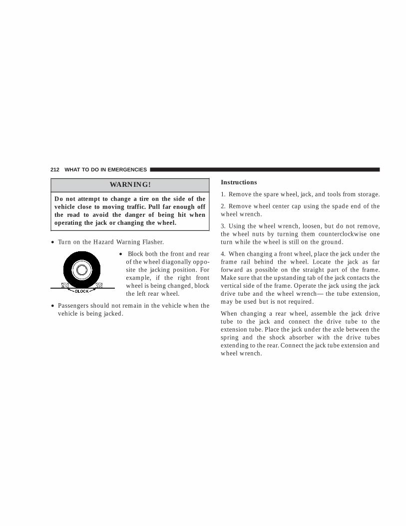
WARNING!
Do not attempt to change a tire on the side of thevehicle close to moving traffic. Pull far enough offthe road to avoid the danger of being hit whenoperating the jack or changing the wheel.
• Turn on the Hazard Warning Flasher.
• Block both the front and rearof the wheel diagonally oppo-site the jacking position. Forexample, if the right frontwheel is being changed, blockthe left rear wheel.
• Passengers should not remain in the vehicle when thevehicle is being jacked.
Instructions
1. Remove the spare wheel, jack, and tools from storage.
2. Remove wheel center cap using the spade end of thewheel wrench.
3. Using the wheel wrench, loosen, but do not remove,the wheel nuts by turning them counterclockwise oneturn while the wheel is still on the ground.
4. When changing a front wheel, place the jack under theframe rail behind the wheel. Locate the jack as farforward as possible on the straight part of the frame.Make sure that the upstanding tab of the jack contacts thevertical side of the frame. Operate the jack using the jackdrive tube and the wheel wrench— the tube extension,may be used but is not required.
When changing a rear wheel, assemble the jack drivetube to the jack and connect the drive tube to theextension tube. Place the jack under the axle between thespring and the shock absorber with the drive tubesextending to the rear. Connect the jack tube extension andwheel wrench.
212 WHAT TO DO IN EMERGENCIES
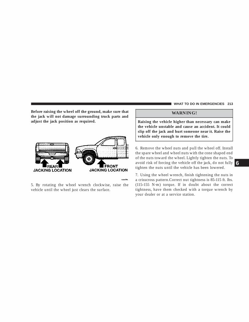
Before raising the wheel off the ground, make sure thatthe jack will not damage surrounding truck parts andadjust the jack position as required.
5. By rotating the wheel wrench clockwise, raise thevehicle until the wheel just clears the surface.
WARNING!
Raising the vehicle higher than necessary can makethe vehicle unstable and cause an accident. It couldslip off the jack and hurt someone near it. Raise thevehicle only enough to remove the tire.
6. Remove the wheel nuts and pull the wheel off. Installthe spare wheel and wheel nuts with the cone shaped endof the nuts toward the wheel. Lightly tighten the nuts. Toavoid risk of forcing the vehicle off the jack, do not fullytighten the nuts until the vehicle has been lowered.
7. Using the wheel wrench, finish tightening the nuts ina crisscross pattern.Correct nut tightness is 85-115 ft. lbs.(115-155 N·m) torque. If in doubt about the correcttightness, have them checked with a torque wrench byyour dealer or at a service station.
WHAT TO DO IN EMERGENCIES 213
6

WARNING!
A loose tire or jack thrown forward in a collision orhard stop could injure someone in the vehicle.Always stow the jack parts and the extra tire andwheel in the places provided.
8. Install wheel center cap and remove wheel blocks. Donot install chrome or aluminum wheel center caps on thespare wheel. This may result in cap damage.
9. Lower the jack to its fully closed position. Stow thereplaced tire, jack, and tools as previously described.
10. Adjust the tire pressure when possible.
NOTE: Do not oil wheel studs. For chrome wheels, donot substitute with chrome plated wheel nuts.
WARNING!
Carefully follow these tire changing warnings tohelp prevent personal injury or damage to yourvehicle:
• Always park on a firm, level surface as far fromthe edge of the roadway as possible before raisingthe vehicle.
• Block the wheel diagonally opposite the wheel tobe raised.
• Apply the parking brake firmly before jacking.
• Never start the engine with the vehicle on a jack.
• Do not let anyone sit in the vehicle when it is ona jack.
• Do not get under the vehicle when it is on a jack.
• Only use the jack in the positions indicated.
• If working on or near a roadway, be extremelycareful of motor traffic.
214 WHAT TO DO IN EMERGENCIES

To Stow The Flat Or SpareTurn the wheel so that the valve stem is down. Slide thewheel retainer through the center of the wheel andposition it properly across the wheel opening.
For convenience in checking the spare tire inflation, stowwith the valve stem toward the rear of the vehicle.
Attach the wheel wrench to the extension tube. Rotate thewinch mechanism until the wheel is drawn into placeagainst the underside of the vehicle. Continue to rotateuntil you feel the winch mechanism slip or click 3 or 4times. It cannot be overtightened. Push against the tireseveral times to be sure it is firmly in place.
JUMP STARTING
WARNING!
• Battery fluid is a corrosive acid solution; do notallow battery fluid to contact eyes, skin or cloth-ing. Don’t lean over battery when attachingclamps or allow the clamps to touch each other. Ifacid splashes in eyes or on skin, flush the con-taminated area immediately with large quantitiesof water.
• A battery generates hydrogen gas which is flam-mable and explosive. Keep flame or spark awayfrom the vent holes. Do not use a booster batteryor any other booster source with an output thatexceeds 12 volts.
Check the Battery Test Indicator (if equipped). If a yellowor bright colored dot is visible in the indicator (ifequipped), DO NOT jump-start the battery.
WHAT TO DO IN EMERGENCIES 215
6

If the indicator (if equipped) is dark or shows a green dot,proceed as follows:
1. Wear eye protection and remove all metal jewelry suchas watch bands or bracelets which might make anunintended electrical contact.
2. Park the booster vehicle within cable reach but with-out letting the vehicles touch. Set the parking brake, placethe automatic transmission in PARK or the manualtransmission in NEUTRAL and turn the ignition OFF onboth vehicles.
3. Turn OFF heater, radio and all unnecessary electricalloads.
4. Connect one end of a jumper cable to the positiveterminal of the booster battery. Connect the other end ofthe same cable to the positive terminal of the dischargedbattery.
WARNING!
Do not permit vehicles to touch each other as thiscould establish a ground connection and personalinjury could result.
5. Connect the other cable, first to the negative terminalof the booster battery and then to the engine of thevehicle with the discharged battery. Make sure you havea good contact on the engine.
216 WHAT TO DO IN EMERGENCIES

WARNING!
Do not connect the cable to the negative post of thedischarge battery. The resulting electrical sparkcould cause the battery to explode.
During cold weather when temperatures are belowfreezing point, electrolyte in a discharged batterymay freeze. Do not attempt jump starting becausethe battery could rupture or explode. The batterytemperature must be brought up above freezingpoint before attempting jump start.
6. Start the engine in the vehicle which has the boosterbattery, let the engine idle a few minutes, then start theengine in the vehicle with the discharged battery.
7. When removing the jumper cables, reverse the abovesequence exactly. Be careful of the moving belts and fan.
WARNING!
Any procedure other than above could result in:
1. Personal injury caused by electrolyte squirtingout the battery vent;
2. Personal injury or property damage due to batteryexplosion;
3. Damage to charging system of booster vehicle orof immobilized vehicle.
TOWING A DISABLED VEHICLEProper towing or lifting equipment is required to preventdamage to your vehicle. Use of safety chains is recom-mended. Attach towing device to main structural mem-bers of the vehicle — not to bumpers or associatedbrackets. State and local laws applying to vehiclesunder tow must be observed.
WHAT TO DO IN EMERGENCIES 217
6

Four-Wheel Drive VehiclesThe manufacturer recommends towing with all wheelsoff the ground. Acceptable methods are to tow the vehicleon a flatbed or with one end of the vehicle raised and theopposite end on a towing dolly.
Two-Wheel Drive Vehicles
Provided that the transmission is operable, tow with thetransmission in Neutral and the ignition key in the OFFposition along with the front wheels raised and the rearwheels on the ground. The speed must not exceed 30mph (50 km/h) and the distance must not exceed 15miles (25 km).
If the vehicle is to be towed more than 15 miles (25 km),it must be towed on a flatbed, or with the rear wheelsraised and the front wheels on the ground, or with thefront end raised and the rear wheels on a towing dolly.
218 WHAT TO DO IN EMERGENCIES

MAINTAINING YOUR VEHICLE
CONTENTS
m Engine Compartment 3.7L V6 . . . . . . . . . . . . . 221
m Engine Compartment 4.7L V-8 . . . . . . . . . . . . 222
m Onboard Diagnostic System — OBD II . . . . . . 223
m Emissions Inspection And MaintenancePrograms . . . . . . . . . . . . . . . . . . . . . . . . . . . . 224
m Replacement Parts . . . . . . . . . . . . . . . . . . . . . 225
m Dealer Service . . . . . . . . . . . . . . . . . . . . . . . . 225
m Maintenance Procedures . . . . . . . . . . . . . . . . . 226
▫ Engine Oil . . . . . . . . . . . . . . . . . . . . . . . . . . 226
▫ Engine Oil Filter . . . . . . . . . . . . . . . . . . . . . . 229
▫ Drive Belts — Check Condition And Tension . . 230
▫ Spark Plugs . . . . . . . . . . . . . . . . . . . . . . . . . 230
▫ Ignition Cables . . . . . . . . . . . . . . . . . . . . . . . 230
▫ Engine Air Cleaner Filter . . . . . . . . . . . . . . . . 230
▫ Engine Fuel Filter . . . . . . . . . . . . . . . . . . . . . 231
▫ Catalytic Converter . . . . . . . . . . . . . . . . . . . . 231
▫ Maintenance-Free Battery . . . . . . . . . . . . . . . . 232
▫ Air Conditioner Maintenance . . . . . . . . . . . . . 233
▫ Power Steering — Fluid Check . . . . . . . . . . . . 234
▫ Front Suspension Ball Joints . . . . . . . . . . . . . . 235
▫ Steering Linkage . . . . . . . . . . . . . . . . . . . . . . 235
▫ Drive Shaft Constant VelocityJoints — 4X4 Models . . . . . . . . . . . . . . . . . . . 235
▫ Body Lubrication . . . . . . . . . . . . . . . . . . . . . 235
7

▫ Windshield Wiper Blades . . . . . . . . . . . . . . . . 235
▫ Windshield Washers . . . . . . . . . . . . . . . . . . . 236
▫ Exhaust System . . . . . . . . . . . . . . . . . . . . . . 236
▫ Cooling System . . . . . . . . . . . . . . . . . . . . . . . 237
▫ Emission Related Components . . . . . . . . . . . . 241
▫ Brake System . . . . . . . . . . . . . . . . . . . . . . . . 243
▫ Clutch Hydraulic System . . . . . . . . . . . . . . . . 245
▫ Manual Transmission . . . . . . . . . . . . . . . . . . 245
▫ Automatic Transmission . . . . . . . . . . . . . . . . 245
▫ Transfer Case . . . . . . . . . . . . . . . . . . . . . . . . 248
▫ Axles . . . . . . . . . . . . . . . . . . . . . . . . . . . . . . 248
▫ Selection Of Lubricating Grease . . . . . . . . . . . 248
▫ Appearance Care And Protection FromCorrosion . . . . . . . . . . . . . . . . . . . . . . . . . . . 249
m Power Distribution Center . . . . . . . . . . . . . . . 252
m Fuse Block . . . . . . . . . . . . . . . . . . . . . . . . . . . 253
m Vehicle Storage . . . . . . . . . . . . . . . . . . . . . . . . 254
m Replacement Light Bulbs . . . . . . . . . . . . . . . . 254
m Bulb Replacement . . . . . . . . . . . . . . . . . . . . . . 255
▫ Headlights . . . . . . . . . . . . . . . . . . . . . . . . . . 255
▫ Parking/Turn Signal Lights . . . . . . . . . . . . . . 256
▫ Rear Side Marker, Tail Lights, Turn SignalsAnd Backup Lights — Replacement . . . . . . . . 256
▫ License Lights . . . . . . . . . . . . . . . . . . . . . . . . 257
▫ Center High-Mounted Stoplight . . . . . . . . . . . 257
▫ Fog Lights . . . . . . . . . . . . . . . . . . . . . . . . . . 257
m Fluids And Capacities . . . . . . . . . . . . . . . . . . . 258
m Recommended Fluids, Lubricants AndGenuine Parts . . . . . . . . . . . . . . . . . . . . . . . . . 259
▫ Engine . . . . . . . . . . . . . . . . . . . . . . . . . . . . . 259
▫ Chassis . . . . . . . . . . . . . . . . . . . . . . . . . . . . 260
220 MAINTAINING YOUR VEHICLE

ENGINE COMPARTMENT 3.7L V6
MAINTAINING YOUR VEHICLE 221
7

ENGINE COMPARTMENT 4.7L V-8
222 MAINTAINING YOUR VEHICLE

ONBOARD DIAGNOSTIC SYSTEM — OBD IIYour vehicle is equipped with a sophisticated onboarddiagnostic system called OBD II. This system monitorsthe performance of the emissions, engine, and automatictransmission control systems. When these systems areoperating properly, your vehicle will provide excellentperformance and fuel economy, as well as engine emis-sions well within current government regulations.
If any of these systems require service, the OBD II systemwill turn on the “Malfunction Indicator Light.” It willalso store diagnostic codes and other information toassist your service technician in making repairs. Al-though your vehicle will usually be drivable and notneed towing, see your dealer for service as soon aspossible.
CAUTION!
• Prolonged driving with the “Malfunction Indica-tor Light” on could cause further damage to theemission control system. It could also affect fueleconomy and driveability. The vehicle must beserviced before any emissions tests can be per-formed.
• If the “Malfunction Indicator Light” is flashingwhile the engine is running, severe catalytic con-verter damage and power loss will soon occur.Immediate service is required.
MAINTAINING YOUR VEHICLE 223
7

EMISSIONS INSPECTION AND MAINTENANCEPROGRAMSIn some localities, it may be a legal requirement to passan inspection of your vehicle’s emissions control system.Failure to pass could prevent vehicle registration.
For states which have an I/M (Inspection andMaintenance) requirement, this check verifies thefollowing: the MIL (Malfunction Indicator Lamp)
is functioning and is not on when the engine is running,and that the OBD (On Board Diagnostic) system is readyfor testing.
Normally, the OBD system will be ready. The OBDsystem may not be ready if your vehicle was recentlyserviced, if you recently had a dead battery, or a batteryreplacement. If the OBD system should be determinednot ready for the I/M test, your vehicle may fail the test.
Your vehicle has a simple ignition key actuated testwhich you can use prior to going to the test station. Tocheck if your vehicle’s OBD system is ready, you must dothe following:
1. Insert your ignition key into the ignition switch.
2. Turn the ignition to the ON position, but do not crankor start the engine.
3. If you crank or start the engine, you will have to startthis test over.
4. As soon as you turn your key to the ON position, youwill see your MIL symbol come on as part of a normalbulb check.
5. Approximately 15 seconds later, one of two things willhappen:
a. The MIL light will blink for approximately 5seconds and then remain on until the first enginecrank or the key is turned off. This means that yourvehicle’s OBD system is not ready and you shouldnot proceed to the I/M station.
b. The MIL light will remain fully illuminated untilthe first engine crank or the key is turned off. Thismeans that your vehicle’s OBD system is ready andyou can proceed to the I/M station.
If your OBD system is not ready, you should see yourdealer or repair facility. If your vehicle was recently
224 MAINTAINING YOUR VEHICLE

serviced or had a battery failure or replacement, you mayneed to do nothing more than drive your vehicle as younormally would in order for your OBD system to update.A recheck with the above test routine may then indicatethat the system is now ready.
Regardless of whether your vehicle’s OBD system isready or not ready, if the MIL symbol is illuminatedduring normal vehicle operation, you should have yourvehicle serviced before going to the I/M station. The I/Mstation can fail your vehicle because the MIL symbol is onwith the engine running.
REPLACEMENT PARTSUse of genuine Mopart parts for normal/scheduledmaintenance and repairs is highly recommended to in-sure the designed performance. Damage or failurescaused by the use of non-Mopart parts for maintenanceand repairs will not be covered by the manufacturer’swarranty.
DEALER SERVICEYour dealer has the qualified service personnel, specialtools and equipment to perform all service operations inan expert manner. Service manuals are available whichinclude detailed service information for your vehicle.Refer to these manuals before attempting any procedureyourself.
NOTE: Intentional tampering with emissions controlsystems can result in civil penalties being assessedagainst you.
WARNING!
You can be badly injured working on or around amotor vehicle. Do only that service work for whichyou have the knowledge and the proper equipment.If you have any doubt about your ability to performa service job, take your vehicle to a competentmechanic.
MAINTAINING YOUR VEHICLE 225
7

MAINTENANCE PROCEDURESThe pages that follow contain the required maintenanceservices determined by the engineers who designed yourvehicle.
Besides the maintenance items for which there are fixedmaintenance intervals, there are other items that shouldoperate satisfactorily without periodic maintenance.However, if a malfunction of these items does occur, itcould adversely affect the engine or vehicle performance.These items should be inspected if a malfunction isobserved or suspected.
Engine Oil
Checking Engine Oil LevelTo assure proper lubrication of your vehicle’s engine, theengine oil must be maintained at the correct level. Thebest time to check the engine oil level is about 5 minutesafter a fully warmed up engine is shut off or beforestarting the engine after it has sat overnight.
Checking the oil while the vehicle is on level ground willimprove the accuracy of the oil level readings. Maintainthe oil level between the ADD and SAFE markings on thedipstick. Adding one quart of oil when the reading is atthe ADD mark will result in a SAFE reading on theseengines.
It is important to check the oil while the vehicle is onlevel ground. Add oil only when the level is at or belowthe ADD OIL mark.
226 MAINTAINING YOUR VEHICLE

CAUTION!
Overfilling or underfilling the crankcase will causeoil aeration or loss of oil pressure. This could dam-age your engine.
Frequency Of Oil ChangeRoad conditions and your style of driving affect theinterval at which your oil should be changed. Check thefollowing to determine if any apply to you:
• Day or night temperatures are below 32°F (0°C).
• Stop and go driving.
• Extensive engine idling.
• Driving in dusty conditions
• Short trips of less than 10 miles (16.2 km)
• More than 50% of your driving is at sustained highspeeds during hot weather, above 32°C (90°F)
• Trailer towing
• Taxi, Police or delivery service (commercial service)
• Off-road or desert operation
• If equipped for and operating with E-85 (ethanol)fuel.
NOTE: If ANY of these apply to you then change yourengine oil every 3,000 miles (5 000 km) or 3 months,whichever comes first and follow schedule “B” of the9Maintenance Schedules9 section of this manual.
If none of these apply to you, then change your engine oilat every interval shown on schedule 9A9 of the 9Mainte-nance Schedules9 section of this manual.
4x4 Models, If Used Primarily For Off-RoadOperationEvery 50 hours of use.
MAINTAINING YOUR VEHICLE 227
7

Dusty ConditionsDriving through dust-laden air increases the problems ofkeeping abrasive materials out of the engine. Under theseconditions, special attention should be given to theengine air cleaner and the crankcase inlet air cleaner. Thecrankcase ventilation system should also be checkedperiodically. Make sure that these units are always clean.This will tend to reduce to a minimum the amount ofabrasive material that may enter the engine.
Engine Oil SelectionFor best performance and maximum protection under alltypes of operating conditions, the manufacture onlyrecommends engine oils that are API certified and meetthe requirements of DaimlerChrysler Material StandardMS-6395. Use Mopar or an equivalent oil meeting thespecification MS-6395.
American Petroleum Institute (API) OilIdentification SymbolThere is a symbol to aid you in selecting the properengine oil.
This symbol means that the oil hasbeen certified by the AmericanPetroleum Institute (API). Themanufacture only recommendsAPI Certified engine oils thatmeet the requirements ofDaimlerChrysler Material Stan-dard MS-6395. Use Mopar or anequivalent oil meeting the specifi-cation MS-6395.
Engine Oil Viscosity ChartThe proper SAE viscosity grade of engine oil should beselected based on the following recommendation and bewithin the operating temperature shown in the recom-mended SAE viscosity chart.
• SAE 5W-30 is the oil recommended in trucks equippedwith a 3.7L/4.7L engine, for optimum fuel economy.
• Synthetic engine oils may be used provided that the oilquality requirements described above are met and therecommended maintenance intervals for oil and filterchanges are followed.
228 MAINTAINING YOUR VEHICLE

• Lubricants which do not have both the engine oilcertification mark or current service symbol and thecorrect viscosity grade number should not be used.
Synthetic Engine OilsThere are a number of engine oils being promoted aseither synthetic or semi-synthetic. If you chose to usesuch a product, use only those oils that meet the Ameri-can Petroleum Institute (API) and SAE viscosity stan-dard. Follow the service schedule that describes yourdriving type.
Materials Added to Engine OilThe manufacture strongly recommends against the addi-tion of any additives (other than leak detection dyes) tothe engine oil. Engine oil is an engineered product andit’s performance may be impaired by supplemental ad-ditives.
Disposing of Used Engine Oil And Oil FiltersCare should be taken in disposing of used engine oil andoil filters from your vehicle. Used oil and oil filters,indiscriminately discarded, can present a problem to theenvironment. Contact your dealer, service station, orgovernmental agency for advice on how and where usedoil and oil filters can be safely discarded in your area.
Engine Oil FilterThe engine oil filter should be replaced at every engineoil change.
Engine Oil Filter SelectionThe manufacturer’s engines have a full-flow type oilfilter. Use a filter of this type for replacement. The qualityof replacement filters varies considerably. Only high
3.7L/4.7L Engines
MAINTAINING YOUR VEHICLE 229
7

quality filters should be used to assure most efficientservice. Mopar Engine Oil Filters are a high quality oilfilter and are recommended.
Drive Belts — Check Condition and TensionAt the mileage indicated in the maintenance schedule, allbelts should be checked for condition and proper tension.Improper belt tension can cause belt slippage and failure.
Belts should be inspected for evidence of cuts, cracks, orglazing, and replaced if there is indication of damagewhich could result in belt failure. If adjustment is re-quired, see your authorized dealer for service. Lowgenerator belt tension can cause battery failure. A specialtool is required to properly measure tension and torestore belt tension to factory specifications.
Also check belt routing to make sure there is no interfer-ence between the belts and other engine components.
Spark PlugsSpark plugs must fire properly to assure proper engineperformance and emission control. The plugs installed inyour vehicle should operate satisfactorily in normalservice for the mileage indicated in the Maintenance
Chart. New plugs should be installed at this mileage. Theentire set should be replaced if there is any malfunctiondue to a faulty spark plug. Check the Vehicle EmissionsControl Information label for the proper type of sparkplug for your vehicle.
CAUTION!
When replacing plugs, do not overtighten. You coulddamage them and cause them to leak.
Ignition CablesReplace the ignition cables at the mileage interval shownin the maintenance charts.
Engine Air Cleaner FilterUnder normal driving conditions, replace the air filter atthe intervals shown on Schedule “A”. If, however, youdrive the vehicle frequently under dusty or severe con-ditions, the filter element should be inspected periodi-cally and replaced if necessary at the intervals shown onSchedule “B”.
230 MAINTAINING YOUR VEHICLE

WARNING!
The air cleaner can provide a measure of protectionin the case of engine backfire. Do not remove the aircleaner unless such removal is necessary for repair ormaintenance. Make sure that no one is near theengine compartment before starting the vehicle withthe air cleaner removed. Failure to do so can result inserious personal injury.
Engine Fuel FilterA plugged fuel filter can cause stalling, limit the speed atwhich a vehicle can be driven or cause hard starting.Should an excessive amount of dirt accumulate in thefuel tank, frequent filter replacement may be necessary.
Catalytic ConverterThe catalytic converter requires the use of unleaded fuelonly. Leaded gasoline will destroy the effectiveness of thecatalyst as an emission control device.
Under normal operating conditions, the catalytic con-verter will not require maintenance. However, it is im-portant to keep the engine properly tuned to assureproper catalyst operation and prevent possible catalystdamage.
CAUTION!
Damage to the catalytic converter can result if yourvehicle is not kept in proper operating condition. Inthe event of engine malfunction, particularly involv-ing engine misfire or other apparent loss of perfor-mance, have your vehicle serviced promptly. Contin-ued operation of your vehicle with a severemalfunction could cause the converter to overheat,resulting in possible damage to the converter and thevehicle.
NOTE: Intentional tampering with emissions controlsystems can result in civil penalties being assessedagainst you.
MAINTAINING YOUR VEHICLE 231
7

WARNING!
A hot exhaust system can start a fire if you park overmaterials that can burn. Such materials might begrass or leaves coming into contact with your ex-haust system. Do not park or operate your vehicle inareas where your exhaust system can contact any-thing that can burn.
In unusual situations involving grossly malfunctioningengine operation, a scorching odor may indicate severeand abnormal catalyst overheating. If this occurs, thevehicle should be stopped, the engine shut off and thevehicle allowed to cool. Thereafter, service, including atune-up to manufacturer’s specifications, should be ob-tained immediately.
To minimize the possibility of catalyst damage:
• Do not shut off the engine or interrupt the ignitionwhen the transmission is in gear and the vehicle is inmotion.
• Do not try to start engine by pushing or towing thevehicle.
• Do not idle the engine with any spark plug wiresdisconnected or removed, such as when diagnostictesting, or for prolonged periods during very roughidling or malfunctioning operating conditions.
Maintenance-Free BatteryAll Dodge trucks are equipped with maintenance-freebatteries. You will never have to add water, nor isperiodic maintenance required.
232 MAINTAINING YOUR VEHICLE

WARNING!
Battery posts, terminals, and related accessories con-tain lead and lead compounds. Always wash handsafter handling the battery.
To determine the battery charge, check the battery testindicator (if equipped) on top of the battery. Refer to theillustration.
CAUTION!
It is essential when replacing the cables on thebattery that the positive cable is attached to thepositive post and the negative cable is attached to thenegative post. Battery posts are marked (+) positiveand negative (-) and identified on the battery case.Also, if a “fast charger” is used while battery is in thevehicle, disconnect both vehicle battery cables be-fore connecting the charger to battery. Do not use a“fast charger” to provide starting voltage.
Air Conditioner MaintenanceFor best possible performance, your air conditionershould be checked and serviced by an Authorized Dealerat the start of each warm season. This service shouldinclude cleaning of the condenser fins and a performancetest. Drive belt tension should also be checked at thistime.
MAINTAINING YOUR VEHICLE 233
7

WARNING!
• Use only refrigerants and compressor lubricantsapproved by the manufacturer for your air condi-tioning system. Some unapproved refrigerants areflammable and can explode, injuring you. Otherunapproved refrigerants or lubricants can causethe system to fail, requiring costly repairs.
• The air conditioning system contains refrigerantunder high pressure. To avoid risk of personalinjury or damage to the system, adding refrigerantor any repair requiring lines to be disconnectedshould be done by an experienced repairman.
Refrigerant Recovery and RecyclingR-134a Air Conditioning Refrigerant is a hydrofluorocar-bon (HFC) that is endorsed by the Environmental Pro-tection Agency and is an ozone-saving product. How-ever, the manufacturer recommends that air conditioningservice be performed by dealers or other service facilitiesusing recovery and recycling equipment.
Power Steering — Fluid CheckChecking the power steering fluid level at a definedservice interval is not required. The fluid should only bechecked if a leak is suspected, abnormal noises areapparent, and/or the system is not functioning as antici-pated. Coordinate inspection efforts through a certifiedDaimlerChrysler Dealership.9
WARNING!
Fluid level should be checked on a level surface andwith the engine off to prevent injury from movingparts and to insure accurate fluid level reading. Donot overfill. Use only manufacturers recommendedpower steering fluid.
If necessary, add fluid to restore to the proper indicatedlevel. With a clean cloth, wipe any spilled fluid from allsurfaces. Refer to Recommended Fluids, Lubricants, andGenuine Parts for correct fluid type.
234 MAINTAINING YOUR VEHICLE

Front Suspension Ball JointsThe ball joints and seals should be inspected wheneverthe vehicle is serviced for other reasons. Damaged sealsshould be replaced to prevent leakage or contaminationof the grease.
Steering LinkageWhenever the vehicle is hoisted, all steering linkagejoints should be inspected for evidence of damage. Dam-aged seals should be replaced to prevent leakage orcontamination of the grease.
Drive Shaft Constant Velocity Joints — 4X4ModelsAll four-wheel drive models are equipped with fourconstant velocity joints. Periodic lubrication of thesejoints is not required. However, the joint boot should beinspected for external leakage or damage periodically. Ifexternal leakage or damage is evident, the joint boot andgrease should be replaced immediately. Continued op-eration could result in failure of the joint due to waterand dirt contamination of the grease. This would requirecomplete replacement of the joint assembly. Refer to theService Manual for the detailed replacement procedure.
Body LubricationLocks and all body pivot points, including such items asseat tracks, doors,liftgate and hood hinges, should belubricated periodically to assure quiet, easy operationand to protect against rust and wear. Prior to the appli-cation of any lubricant, the parts concerned should bewiped clean to remove dust and grit; after lubricatingexcess oil and grease should be removed. Particularattention should also be given to hood latching compo-nents to insure proper function. When performing otherunderhood services, the hood latch, release mechanismand safety catch should be cleaned and lubricated.
The external lock cylinders should be lubricated twice ayear, preferably in the fall and spring. Apply a smallamount of a high quality lubricant such as Mopart LockCylinder Lubricant directly into the lock cylinder.
Windshield Wiper BladesThe rubber edges of the wiper blades and the windshieldshould be cleaned periodically with a sponge or soft clothand a mild nonabrasive cleaner. This will remove accu-mulations of salt or road film.
MAINTAINING YOUR VEHICLE 235
7

Operation of the wipers on dry glass for long periodsmay cause deterioration of the wiper blades. Always usewasher fluid when using the wipers to remove salt or dirtfrom a dry windshield.
Avoid using the wiper blades to remove frost or ice fromthe windshield. Keep the blade rubber out of contact withpetroleum products such as engine oil, gasoline, etc.
Windshield WashersThe fluid reservoir should be checked for fluid level atregular intervals. When freezing weather is anticipated,flush out the water in the reservoir by operating thesystem. Fill the reservoir with windshield washer anti-freeze (not radiator antifreeze), and operate the systemfor a few seconds to flush out the residual water.
To prevent freeze-up of your windshield washer systemin cold weather, select a solution or mixture that meets orexceeds the temperature range of your climate. Thisrating information can be found on most washer fluidcontainers.
WARNING!
Commercially available windshield washer solventsare flammable. They could ignite and burn you. Caremust be exercised when filling or working aroundthe washer solution.
After the engine has warmed, operate the defroster for afew minutes to reduce the possibility of smearing orfreezing the fluid on the cold windshield. Mopar AllWeather Windshield Washer Solution used with water asdirected on the container, aids cleaning action, reducesfreezing point to avoid line clogging, and is not harmfulto paint or trim.
Exhaust SystemThe best protection against carbon monoxide entry intothe vehicle body is a properly maintained engine exhaustsystem.
236 MAINTAINING YOUR VEHICLE

Whenever a change is noticed in the sound of the exhaustsystem, when exhaust fumes can be detected inside thevehicle, or when the underside or rear of the vehicle isdamaged, have a competent mechanic inspect the com-plete exhaust system and adjacent body areas for broken,damaged, deteriorated, or mispositioned parts. Openseams or loose connections could permit exhaust fumesto seep into the passenger compartment. In addition,inspect the exhaust system each time the vehicle is raisedfor lubrication or oil change. Replace as required.
WARNING!
Exhaust gases can injure or kill. They contain carbonmonoxide (CO) which is colorless and odorless.Breathing it can make you unconscious and caneventually poison you. To avoid breathing CO, fol-low the preceding safety tips.
Cooling System
InspectionCoolant protection checks should be made at every 12months (before the onset of freezing weather, whereapplicable). If coolant is dirty or rusty in appearance, thesystem should be drained, flushed and refilled with freshcoolant. Check face of radiator for any accumulation ofbugs, leaves, etc. If dirty, clean the radiator core by gentlyspraying water from a garden hose at the back of the core.
Check the reserve tank tubing for condition and tightnessof connection at reserve tank and radiator. Inspect theentire system for leaks.
With the engine at normal operating temperature (butnot running), check the coolant pressure cap for propervacuum sealing by draining a small amount of coolantfrom the radiator drain cock. If the cap is sealing prop-erly, the coolant will begin to drain from the reserve tank.Do not remove the pressure cap when the cooling systemis hot.
MAINTAINING YOUR VEHICLE 237
7

WARNING!
You or others can be badly burned by hot coolant orsteam from your radiator. If you see or hear steamcoming from under the hood don’t open the hooduntil the radiator has had time to cool. If you openthe hood and see steam or hot coolant escaping fromthe radiator, don’t touch anything. Get away quickly.Never try to open a pressure cap when the radiator ishot.
Cooling System MaintenanceAt the intervals shown on the Maintenance Schedules,the system should be drained, flushed and filled.
Cooling System — Drain, Flush And RefillIf the solution is dirty and contains a considerableamount of sediment, clean and flush with a reliablecooling system cleaner. Follow with a thorough rinsing toremove all deposits and chemicals. Discard old antifreezesolution according to recommended procedure.
Disposal of Used Engine CoolantUsed ethylene glycol-based engine coolant is a regulatedsubstance requiring proper disposal. Check with yourlocal authorities to determine the disposal rules for yourcommunity. Do not store ethylene glycol-based enginecoolant in open containers or allow it to remain inpuddles on the ground. Prevent ingestion by animals andchildren. If ingested by a child, contact a physicianimmediately. Clean up any ground spills immediately.
Recommended Engine CoolantRefer to Recommended Fluids, Lubricants and GenuineParts for correct fluid type.
238 MAINTAINING YOUR VEHICLE

CAUTION!
Mixing of coolants other than specified (non-HOAT), may result in engine damage that may notbe covered under the new vehicle warranty, anddecreased corrosion protection. If a non-HOAT cool-ant is introduced into the cooling system in anemergency, it should be replaced with the specifiedcoolant as soon as possible.
Do not use plain water alone or alcohol base anti-freeze products. Do not use additional rust inhibi-tors or antirust products, as they may not be compat-ible with the radiator coolant and may plug theradiator.
This vehicle has not been designed for use withPropylene Glycol based coolants. Use of PropyleneGlycol based coolants is not recommended.
Adding CoolantWhen adding coolant or refilling system, a 50% solutionof ethylene glycol antifreeze coolant in water should be
used. Higher concentrations (not to exceed 65%) arerequired if temperatures below –37°F (– 38°C) are antici-pated.
Use only high purity water such as distilled or deionizedwater when mixing the water/antifreeze solution. Theuse of lower quality water will reduce the amount ofcorrosion protection in the engine cooling system.
Please note that it is the owner’s responsibility to main-tain the proper level of protection against freezing ac-cording to the temperatures occurring in the area wherethe vehicle is operated.
WARNING!
Never add coolant to the radiator when the engine isoverheated. Do not loosen or remove pressure cap tocool overheated engine. The coolant is under pres-sure and severe scalding could result.
MAINTAINING YOUR VEHICLE 239
7

Coolant Pressure CapThe coolant pressure cap must be fully tightened toprevent loss of coolant, and to insure that coolant willreturn to the radiator from the coolant reserve tank.
The pressure cap should be inspected and cleaned if thereis any accumulation of foreign material on the sealingsurfaces.
WARNING!
The warning words “DO NOT OPEN HOT” on thecoolant pressure cap are a safety precaution. Heatcauses pressure to build up in the cooling system. Toprevent scalding or injury, do not remove the pres-sure cap when the system is hot or under pressure.
Coolant Level
The coolant reserve system provides a quick visualmethod for determining that the coolant level is ad-equate. With the engine idling, and warmed to normaloperating temperature, remove the cap from the over-flow bottle, remove the dipstick and wipe the excesscoolant from it. Reinsert the dipstick and remove. Ob-serve the dipstick checking the holes along the stem forcoolant. Check the coolant level whenever the hood israised.
240 MAINTAINING YOUR VEHICLE

The radiator normally remains completely full, so there isno need to remove the pressure cap except when check-ing coolant freeze point or when replacing coolant. Yourservice attendant should be advised of this. When addi-tional coolant is needed to maintain the proper level, itshould be added to the overflow bottle. Do not overfill.
Points To Remember
A. Do not overfill the reserve tank (overflow bottle).
B. Check coolant freeze point in the radiator and in thereserve tank. If antifreeze needs to be added, contents ofreserve tank also must be protected against freezing.
C. If frequent coolant additions are required, or if thelevel in the reserve tank does not drop when the enginecools, the cooling system should be pressure tested forleaks.
D. Maintain a minimum coolant concentration of 50%ethylene glycol.
E. Make sure that the radiator and reserve tank overflowhoses are not kinked or obstructed.
F. Keep the front of the radiator clean. If your vehicle isequipped with air conditioning, keep the front of thecondenser clean also.
G. The thermostat should not be changed for summer orwinter operation. If replacement is ever necessary, installONLY the correct type thermostat. Other designs mayresult in unsatisfactory cooling performance.
Emission Related Components
Fuel System Hoses And Vapor/Vacuum HarnessesWhen the vehicle is serviced for scheduled maintenance,inspect surface of hoses and nylon tubing for evidence ofheat and mechanical damage. Hard and brittle rubber,cracking, checking, tears, cuts, abrasions, and excessiveswelling suggest deterioration of the rubber. Particularattention should be given to examining hose surfacesnearest to high heat sources, such as the exhaust mani-fold.
MAINTAINING YOUR VEHICLE 241
7

Insure nylon tubing in these areas has not melted orcollapsed.
Inspect all hose clamps and couplings to make sure theyare secure and no leaks are present.
NOTE: Fluids such as oil, power steering fluid, andbrake fluid are used during assembly plant operations toease the assembly of hoses to couplings. Therefore, oilwetness at the hose-coupling area is not necessarily anindication of leakage. Actual dripping of hot fluid whensystems are under pressure (during vehicle operation),should be noted before hose is replaced based on leakage.
You are urged to use only manufacturer specified hosesand clamps, or their equivalent in material and specifi-cation, in any fuel system servicing. It is mandatory toreplace all clamps that have been loosened or removedduring service. Care should be taken in installing newclamps to insure they are properly torqued.
Positive Crankcase Ventilation (PCV) ValveProper operation of the crankcase ventilation systemrequires that the PCV valve be free of sticking or plug-ging because of deposits. Deposits can accumulate in the
PCV valve and passage with increasing mileage. Havethe PCV valve, hoses, and passages checked for properoperation at the intervals specified. If the valve isplugged or sticking, replace with a new valve. Do notattempt to clean the oil PCV valve! Check ventilatinghose for indication of damage or plugging with deposits.Replace if necessary.
242 MAINTAINING YOUR VEHICLE

Brake System
Power Disc Brakes (Front)Disc brakes do not require adjustment; however, severalhard stops during the break-in period are recommendedto seat the linings and wear off any foreign material.
Self-Adjusting Rear BrakesTo maintain the correct adjustment, you need only driveyour vehicle in reverse and apply the brakes. If furtheradjustment is needed, drive forward about 20 feet (6meters) before you repeat the reverse application. Toavoid poor braking, brake pull, or damage to brakedrums, the brake linings should be inspected as specifiedin the Maintenance Schedule.
Brake Master CylindersThe fluid level in the master cylinders should be checkedwhenever the vehicle is serviced, or immediately if thebrake system warning light is on. If necessary, add fluidto bring level to the full mark on the side of the reservoirof the brake master cylinder. Be sure to clean the top ofthe master cylinder area before removing the cap. Withdisc brakes, fluid level can be expected to fall as the brake
pads wear. Brake fluid level should be checked whenpads are replaced. If the brake fluid level is abnormallylow, check system for leaks.
Refer to Recommended Fluids, Lubricants and GenuineParts for correct fluid type.
MAINTAINING YOUR VEHICLE 243
7

WARNING!
Use of brake fluid that may have a lower initialboiling point, or is unidentified as to specifications,may result in sudden brake failure during hardprolonged braking. You could have an accident.
WARNING!
Overfilling the brake fluid reservoir can result inspilling brake fluid on hot engine parts and thebrake fluid catching fire.
Use only brake fluid that has been in a tightly closedcontainer to avoid contamination from foreign matter ormoisture.
CAUTION!
Do not allow a petroleum-base fluid to contaminatethe brake fluid. Seal damage may result.
Brake LiningsYour vehicle is equipped with self-adjusting brakes. Afew brake applications while moving in reverse willmaintain your brakes at the specified adjustment. Adjust-ment will continue until the brake linings are worn. Toavoid brake failure, brake pull or damage to drums,inspect the brake linings as specified. If excessively worn,the brake linings must be replaced.
Brake HosesInspection should be performed whenever the brakesystem is serviced or at intervals specified. Inspect hy-draulic brake hoses for surface cracking, scuffing or wornspots. If there is any evidence of cracking, scuffing, orworn spots, the hose should be replaced immediately!Eventual deterioration of the hose can take place withpossible burst failure.
244 MAINTAINING YOUR VEHICLE

WARNING!
Worn brake hoses can burst and cause brake failure.You could have an accident. If you see any sign ofcracking, scuffing, or worn spots, have the brakehoses replaced immediately.
Clutch Hydraulic SystemThe clutch hydraulic system is a sealed maintenance freesystem. In the event of leakage or other malfunction, thesystem must be replaced.
Manual Transmission
Fluid Level CheckThis fluid should be checked whenever other underhoodservices are performed. The fluid level is checked byremoving the fill plug. If the level of the lubricant is morethan 1/49 (6.35 mm) below the bottom of the filler holewhile the vehicle is level, enough lubricant should beadded to bring the level to the bottom of the filler hole.
NV-3500 5-Speed Transmission Lubricant SelectionThese transmissions are filled with manual transmissionfluid at the factory. This fluid does not require periodicchanging. If it becomes necessary to add or change thefluid in these transmissions, Refer to RecommendedFluids, Lubricants and Genuine Parts for correct fluidtype.
Automatic Transmission
Fluid Level Check – 3.7/4.7L EngineCheck the fluid level while the transmission is at normaloperating temperature 180°F (82°C). This occurs after atleast 15 miles (25 km) of driving. At normal operatingtemperature the fluid cannot be held comfortably be-tween the fingertips.
To check the automatic transmission fluid level properly,the following procedure must be used:
1. Operate the engine at idle speed and normal operatingtemperature.
2. The vehicle must be on level ground.
MAINTAINING YOUR VEHICLE 245
7

3. Fully apply the parking brake and press the brakepedal.
4. Place the gear selector momentarily in each gearposition ending with the lever in P (Park).
5. Remove the dipstick, wipe it clean and reinsert it untilseated.
6. Remove the dipstick again and note the fluid level onboth sides. The fluid level should be between the “HOT”(upper) reference holes on the dipstick at normal operat-ing temperature. Verify that solid coating of oil is seen on
both sides of the dipstick. If the fluid is low, add asrequired into the dipstick tube. Do not overfill. Afteradding any quantity of oil through the oil fill tube, waita minimum of two (2) minutes for the oil to fully draininto the transmission before rechecking the fluid level.
NOTE: If it is necessary to check the transmissionbelow the operating temperature, the fluid level shouldbe between the two “COLD” (lower) holes on the dip-stick with the fluid at approximately 70°F (21°C) (roomtemperature). If the fluid level is correctly established atroom temperature, it should be between the “HOT”(upper) reference holes when the transmission reaches180°F ( 82°C). Remember it is best to check the level at thenormal operating temperature.
CAUTION!
Be aware that if the fluid temperature is below 50°F(10°C) it may not register on the dipstick. Do not addfluid until the temperature is elevated enough toproduce an accurate reading.
246 MAINTAINING YOUR VEHICLE

7. Check for leaks. Release parking brake.
To prevent dirt and water from entering the transmissionafter checking or replenishing fluid, make certain that thedipstick cap is properly reseated. It is normal for thedipstick cap to spring back slightly from its fully seatedposition, as long as its seal remains engaged in thedipstick tube.
Automatic Transmission Fluid And Filter ChangeTo obtain best performance and long life for automatictransmissions, the manufacturer recommends that theybe given regular maintenance service by an AuthorizedDodge Dealer or Service Center. It is important that thetransmission be adjusted periodically, the fluid be main-tained at the correct level, and that it be drained andrefilled as specified.
It is important that proper lubricant is used in thetransmission. Refer to Recommended Fluids, Lubricantsand Genuine Parts for correct fluid type. It is importantthat the transmission fluid be maintained at the pre-scribed level using the recommended fluid.
CAUTION!
Using a transmission fluid other than the manufac-turers recommended fluid may cause deteriorationin transmission shift quality and/or torque convertershudder. Using a transmission fluid other than themanufacturers recommended fluid will result inmore frequent fluid and filter changes. Refer toRecommended Fluids, Lubricants and Genuine Partsfor correct fluid type.
Refer to the “Maintenance Schedules” section for theproper service intervals for your type of driving.
If the transmission is disassembled for any reason, thefluid and filter should be changed, and the bands ad-justed (if equipped).
Special AdditivesThe manufacturer strongly recommends against the ad-dition of any fluid additives to the transmission. Excep-tion to this policy is the use of special dyes to aid indetecting fluid leaks. The use of transmission sealersshould be avoided, since they may adversely affect seals.
MAINTAINING YOUR VEHICLE 247
7

Transfer CaseInspect the transfer case for fluid leaks. If a fluid leak isevident the transfer case fluid level can be checked byremoving the filler plug located on the back side of thetransfer case. The fluid level should be at the bottom edgeof the filler plug hole when the vehicle is in a levelposition.
The transfer case fluid should be drained and refilled atthe intervals specified.
Lubricant SelectionRefer to Recommended Fluids, Lubricants and GenuineParts for correct fluid type.
AxlesRefer to Recommended Fluids, Lubricants and GenuineParts for correct fluid type.
The manufacturer does not recommend regularly sched-uled oil changes for axles in vehicles whose operation isclassified as normal truck service.
NOTE: The presence of water in the gear lubricant willresult in corrosion and possible failure of differentialcomponents. Operation of the vehicle in water, as may be
encountered in some off-highway types of service, willrequire draining and refilling the axle to avoid damage.
Rear AxleLimited-slip differentials require the use of Mopart lim-ited slip additive. Refer to Recommended Fluids, Lubri-cants and Genuine Parts for correct fluid type. Thisshould be added to the gear lubricant whenever a fluidchange is made, when equipped with a limited-slipdifferential. Rear axle fluid level should be 1/49 (6.35mm) below filler plug hole for 8 1/4 axles and should be5/89 (16 mm) below filler plug hole for 9 1/49 axles.
Front AxleFront axle fluid level should be at the bottom of the fillerplug hole.
Selection of Lubricating GreaseThe National Lubricating Grease Institute (NLGI) hasdeveloped a symbol (Certification Mark) to aid thevehicle owner in the proper selection of grease for chassiscomponents. This symbol, an example shown below, islocated on the grease container and identifies the appli-cation and quality of the grease.
248 MAINTAINING YOUR VEHICLE

There are two groupsidentified, those for wheelbearings (Letter “G”) andthose for chassis (Letter“L”) lubrication. Perfor-mance categories withinthese groups result in dualletter designations foreach group. The letter des-ignations shown in the ex-ample are the highest
quality level available and when combined as shown canbe used for chassis lubrication. Use only those greasesthat have the NLGI symbol on the container along withthe proper quality level for your application.
Appearance Care and Protection from Corrosion
Protection of Body and Paint from CorrosionVehicle body care requirements vary according to geo-graphic locations and usage. Chemicals that make roadspassable in snow and ice, and those that are sprayed ontrees and road surfaces during other seasons, are highlycorrosive to the metal in your vehicle. Outside parking,
which exposes your vehicle to airborne contaminants,road surfaces on which the vehicle is operated, extremehot or cold weather and other extreme conditions willhave an adverse effect on paint, metal trim, and under-body protection.
The following maintenance recommendations will enableyou to obtain maximum benefit from the corrosionresistance built into your vehicle.
What Causes Corrosion?Corrosion is the result of deterioration or removal ofpaint and protective coatings from your vehicle.
The most common causes are:
• Road salt, dirt and moisture accumulation.
• Stone and gravel impact.
• Insects, tree sap and tar.
• Salt in the air near seacoast localities.
• Atmospheric fallout/industrial pollutants.
MAINTAINING YOUR VEHICLE 249
7

Washing
• Wash your vehicle regularly. Always wash your ve-hicle in the shade using a mild car wash soap, andrinse the panels completely with clear water.
• If insects, tar or other similar deposits have accumu-lated on your vehicle, wash it as soon as possible.
• Use Mopar auto polish to remove road film and stainsand to polish your vehicle. Take care never to scratchthe paint.
• Avoid using abrasive compounds and power buffingthat may diminish the gloss or thin out the paintfinish.
CAUTION!
Do not use abrasive or strong cleaning materialssuch as steel wool or scouring powder, which willscratch metal and painted surfaces.
Special Care
• If you drive on salted or dusty roads or if you drivenear the ocean, hose off the undercarriage at least oncea month.
• It is important that the drain holes in the lower edgesof the doors, rocker panels and tailgate be kept clearand open.
• If you detect any stone chips or scratches in the paint,touch them up immediately. The cost of such repairs isconsidered the responsibility of the owner.
• If your vehicle is damaged due to an accident orsimilar cause which destroys the paint and protectivecoating have your vehicle repaired as soon as possible.The cost of such repairs is considered the responsibil-ity of the owner.
• All wheels and wheel trim, especially aluminum andchrome plated wheels should be cleaned regularlywith mild soap and water to prevent corrosion. Toremove heavy soil, select a nonabrasive, non-acidiccleaner. Do not use scouring pads, steel wool, a bristlebrush or metal polishes. Only Mopar cleaners are
250 MAINTAINING YOUR VEHICLE

recommended. Do not use oven cleaner. Avoid auto-matic car washes that use acidic solutions or harshbrushes that may damage the wheels’ protective fin-ish.
• If you carry special cargo such as chemicals, fertilizers,de-icer salt, etc., be sure that such materials are wellpackaged and sealed.
• If a lot of driving is done on gravel roads, considermud or stone shields behind each wheel.
• Use Mopar touch up paint on scratches as soon aspossible. Your dealer has touch up paint to match thecolor of your vehicle.
Interior CareUse Mopar Fabric Cleaner to clean fabric upholstery andcarpeting.
Use Mopar Vinyl Cleaner to clean vinyl upholstery andtrim.
Mopar Total Clean is specifically recommended forleather upholstery.
Your leather upholstery can be best preserved by regularcleaning with a damp soft cloth. Small particles of dirtcan act as an abrasive and damage the leather upholsteryand should be removed promptly with a damp cloth.Stubborn soils can be removed easily with a soft clothand Mopar Total Clean. Care should be taken to avoidsoaking your leather upholstery with any liquid. Pleasedo not use polishes, oils, cleaning fluids, solvents, deter-gents, or ammonia based cleaners to clean your leatherupholstery. Application of a leather conditioner is notrequired to maintain the original condition.
WARNING!
Do not use volatile solvents for cleaning purposes.Many are potentially flammable, and if used inclosed areas they may cause respiratory harm.
Glass SurfacesAll glass surfaces should be cleaned on a regular basiswith any commercial household-type glass cleaner.Never use an abrasive type cleaner. Use caution whencleaning inside rear windows equipped with electric
MAINTAINING YOUR VEHICLE 251
7

defrosters or windshields equipped with a windshieldwiper de-icer. Do not use scrapers or other sharp instru-ments which may scratch the elements.
When cleaning the rear view mirror, spray cleaner on thetowel or rag that you are using. Do not spray cleanerdirectly on the mirror.
Cleaning Plastic Instrument Cluster LensesThe lenses in front of the instruments in this vehicle aremolded in clear plastic. When cleaning the lenses, caremust be taken to avoid scratching the plastic.
1. Clean with a wet soft rag. A mild soap solution may beused, but do not use high alcohol content or abrasivecleaners. If soap is used, wipe clean with a clean damprag.
2. Dry with a soft tissue.
Seat Belt MaintenanceDo not bleach, dye or clean the belts with chemicalsolvents or abrasive cleaners. This will weaken the fabric.Sun damage will also weaken the fabric.
If the belts need cleaning, use a mild soap solution orlukewarm water. Do not remove the belts from the car towash them.
Replace the belts if they appear frayed or worn or if thebuckles do not work properly.
POWER DISTRIBUTION CENTERYour vehicle is equipped with an electrical Power Distri-bution Center located in the engine compartment nearthe battery.
252 MAINTAINING YOUR VEHICLE

This power center houses plug-in cartridge and relays. Alabel inside the latching cover of the center identifies eachcomponent for ease of replacement, if necessary. Car-tridge fuses and relays can be obtained from your Dodgedealer.
FUSE BLOCKThe fuse block contains blade-type mini-fuses, relays,and circuit breakers for high-current circuits. It is locatedjust inboard of the left end of the instrument panel,behind the panel surface. It is accessible through asnap-in cover. Refer to the label on the backside of thefuse block cover for the proper fuse amperage andposition. CAUTION!
When replacing a blown fuse, it is important to useonly a fuse having the correct amperage rating. Theuse of a fuse with a rating other than indicated mayresult in a dangerous electrical system overload. If aproperly rated fuse continues to blow, it suggests aproblem in the circuit that must be corrected.
MAINTAINING YOUR VEHICLE 253
7

NOTE: If you are leaving your vehicle dormant forlonger than 21 days, you may want to take steps toprotect your battery. You may do this by disconnectingthe battery or by disconnecting the ignition-off draw(I.O.D.) fuse in cavity #12. The I.O.D. cavity includes asnap-in retainer that allows the fuse to be disconnected,without removing it from the fuse block. Pressing theI.O.D. fuse back into the cavity reconnects it.
VEHICLE STORAGEIf you are storing your vehicle for more than 21 days, werecommend that you take the following steps to mini-mize the drain on your vehicle’s battery:
• Disconnect the Ignition-Off Draw fuse (I.O.D.) fuselocated in cavity #12 of the fuse block. The I.O.D.cavity includes a snap-in retainer that allows the fuseto be disconnected, without removing it from the fuseblock.
• The transfer case should be placed in the 4HI modeand kept in this position to minimize the battery drain.
• As an alternative to the above steps you may discon-nect the negative cable from the battery.
REPLACEMENT LIGHT BULBS
LIGHT BULBS — Inside Bulb No.A/C Control. . . . . . . . . . . . . . . . . . . . . . . . . . . . . 74Ash Tray . . . . . . . . . . . . . . . . . . . . . . . . . . . . . . 161Brake System Warning Indicator . . . . . . . . . . . . . . 194Dome Light . . . . . . . . . . . . . . . . . . . . . . . . . . . . 579EGR Reminder . . . . . . . . . . . . . . . . . . . . . . . . . . 194Glove Box. . . . . . . . . . . . . . . . . . . . . . . . . . . . . . 194Heater Control . . . . . . . . . . . . . . . . . . . . . . . . . . 158High Beam Indicator . . . . . . . . . . . . . . . . . . . . . . 194Instrument Cluster. . . . . . . . . . . . . . . . . . . . . . . . 194Low Fuel Indicator . . . . . . . . . . . . . . . . . . . . . . . 194Low Washer Fluid Indicator . . . . . . . . . . . . . . . . . 194Oil Indicator . . . . . . . . . . . . . . . . . . . . . . . . . . . . 194Overhead Console . . . . . . . . . . . . . . . . . . . . . . . . 578Seat Belt Indicator . . . . . . . . . . . . . . . . . . . . . . . . 194Switched Dome . . . . . . . . . . . . . . . . . . . . . . . . . . 578Temperature Indicator . . . . . . . . . . . . . . . . . . . . . 194Turn Signals . . . . . . . . . . . . . . . . . . . . . . . . . . . . 194Underhood Light. . . . . . . . . . . . . . . . . . . . . . . . . 5614x4 Shift Indicator . . . . . . . . . . . . . . . . . . . . . . . . 161
254 MAINTAINING YOUR VEHICLE

LIGHT BULBS — Outside Bulb No.Headlight . . . . . . . . . . . . . . . . . . . . . . . . . . . 9007LLBack-Up . . . . . . . . . . . . . . . . . . . . . . . . . . . . . . 3157Center High Mounted Stoplight . . . . . . . . . . . . . . 921Fog Lamp . . . . . . . . . . . . . . . . . . . . . . . . . . . . . 881LFront Sidemarker. . . . . . . . . . . . . . . . . . . . . . . . . 168License Plate Light . . . . . . . . . . . . . . . . . . . . . . . 168Park & Turn Signal (2) . . . . . . . . . . . . . . . . . . . . 3157Tail, Stop, & Sidemarker . . . . . . . . . . . . . . . . . . . 3157Cargo (2) . . . . . . . . . . . . . . . . . . . . . . . . . . . . . . 921
BULB REPLACEMENT
Headlights
1. Open the hood.
2. Remove the screw as shown and pull the parking/turn signal housing out.
3. Disconnect connectors from the parking/turn signallamp.
MAINTAINING YOUR VEHICLE 255
7

4. Remove the bolts attaching the headlamp to the innerfender panel.
5. Grasp the headlamp and pull firmly to disengage itfrom the panel.
6. Disconnect all connectors and separate the headlampmodule from the vehicle
7. Remove the retaining ring holding the bulb to theheadlamp.
8. Pull the bulb socket from the headlamp and pull thebulb from the socket.
NOTE: These are Halogen bulbs. Take care not to touchthe bulb with your fingers.
Parking/Turn Signal Lights
1. Remove the screw as shown and pull the parking/turn signal housing out.
2. Turn the bulb and socket assembly 1/4 turn and pullto remove socket from housing.3. The bulb can be removed from the socket by pullingstraight out.NOTE: Body oils from your fingers could cause exces-sive heat buildup which reduces bulb life.
Rear Side Marker, Tail Lights, Turn Signals AndBackup Lights — Replacement
1. Remove the screws as illustrated. Grasp the tail lighthousing and pull it rearward.
256 MAINTAINING YOUR VEHICLE
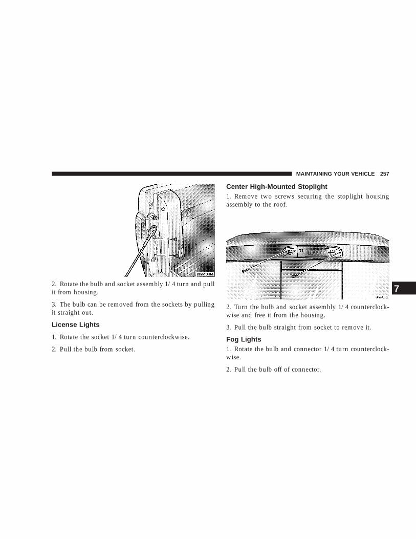
2. Rotate the bulb and socket assembly 1/4 turn and pullit from housing.
3. The bulb can be removed from the sockets by pullingit straight out.
License Lights
1. Rotate the socket 1/4 turn counterclockwise.
2. Pull the bulb from socket.
Center High-Mounted Stoplight1. Remove two screws securing the stoplight housingassembly to the roof.
2. Turn the bulb and socket assembly 1/4 counterclock-wise and free it from the housing.
3. Pull the bulb straight from socket to remove it.
Fog Lights1. Rotate the bulb and connector 1/4 turn counterclock-wise.
2. Pull the bulb off of connector.
MAINTAINING YOUR VEHICLE 257
7

FLUIDS AND CAPACITIES
U.S. MetricFuel
Regular/Club Cab, 87 Octane 20 Gal. w/ORVR, 22 Gal.w/o ORVR
76L w/ORVR, 83L w/oORVR
Quad Cab, 87 Octane 24 Gal. 91LEngine Oil (with filter)
3.7L, SAE 5W-30, API Certified 5 Qt. 4.7L4.7L, SAE 5W-30, API Certified 6 Qt. 5.7L
Cooling System3.7L (Mopart Antifreeze/Coolant 5 Year/100,000 Mile
Formula) NA NA
4.7L (Mopart Antifreeze/Coolant 5 Year/100,000 MileFormula) 17 Qt. 16L
258 MAINTAINING YOUR VEHICLE

RECOMMENDED FLUIDS, LUBRICANTS AND GENUINE PARTSEngine
Component Fluids, Lubricants and Genuine PartsEngine Coolant Mopart Antifreeze/Coolant 5 Year/100,000 Mile Formula HOAT (Hybrid Or-
ganic Additive Technology) P/N 5011764AB or equivalent.Engine Oil Use SAE 5W-30, API Certified, meeting material standard MS-6395.Engine Oil Filter Mopart Engine Oil Filter, P/N 5281090 or equivalent.Spark Plugs Refer to the Vehicle Emission Control Information label in the engine com-
partment.Fuel Selection 87 Octane, (R+M)/2 Method
MAINTAINING YOUR VEHICLE 259
7

Chassis
Component Fluids, Lubricants and Genuine Parts.Automatic Transmission Mopart ATF+4, Automatic Transmission Fluid.Manual Transmission (NV 3500) Mopart Manual Transmission Fluid, part number 4874464Transfer Case Mopart ATF+4, Automatic Transmission Fluid.Front and Rear Axles SAE 75W-90 Multipurpose Type, GL-5 Gear Lubricant. Limited-Slip Rear
Axles Require Mopart limited slip additive. Four (4) ounces (118 ml)should be added to the gear lubricant whenever a fluid change is made.
Rear Axle Fluid for Trailer Towing For all trailer towing or heavy duty applications, replace the factory fillrear axle fluid with Mopart Synthetic Gear Lubricant SAE 75W-140 (MS-8985)
Brake Master Cylinder Mopart DOT 3 and SAE J1703 should be used. If DOT 3 brake fluid is notavailable, then DOT 4. Use only recommended brake fluids.
Power Steering Reservoir Mopart ATF+4, Automatic Transmission Fluid.Steering Linkage Mopart Multi-Mileage Lubricant 5Ball Joints Mopart Multi-Mileage Lubricant 5
260 MAINTAINING YOUR VEHICLE

MAINTENANCE SCHEDULES
CONTENTS
m Emission Control System Maintenance . . . . . . 262
m Emissions Testing . . . . . . . . . . . . . . . . . . . . . . 262
m Maintenance Schedules . . . . . . . . . . . . . . . . . . 263
▫ Schedule “B” . . . . . . . . . . . . . . . . . . . . . . . . 265
▫ Schedule “A” . . . . . . . . . . . . . . . . . . . . . . . . 274
8
MAINTENANCE
SCHEDULES

EMISSION CONTROL SYSTEM MAINTENANCEThe “Scheduled” maintenance services, listed in boldtype on the following pages must be done at the times ormileages specified to assure the continued proper func-tioning of the emission control system. These, and allother maintenance services included in this manual,should be done to provide best vehicle performance andreliability. More frequent maintenance may be needed forvehicles in severe operating conditions such as dustyareas and very short trip driving.
Inspection and service also should be done any time amalfunction is suspected.
NOTE: Maintenance, replacement, or repair of theemission control devices and systems on your vehiclemay be performed by any automotive repair establish-ment or individual using any automotive part which hasbeen certified pursuant to U.S. EPA or, in the State ofCalifornia, California Air Resources Board regulations.
EMISSIONS TESTINGIn some localities, it may be or will become a legalrequirement to ensure that all emissions components andsystems are functioning properly as a part of the testprocedure. The test center accomplishes this by checkingthe On Board Diagnostic System (OBD) system with anelectronic scan tool. If your vehicle has recently beenserviced, the OBD system may have been reset to a 9notready9 condition because the OBD system has not hadsufficient time since the servicing to reconfirm thatemissions components are operating properly. In mostcases, a reasonable mix and amount of normal city andhighway driving and at least one overnight-off periodwill be required to prepare your vehicle for this check;however your dealer has the equipment and proceduresrequired to make certain that the OBD system of yourvehicle is ready for the required testing.
262 MAINTENANCE SCHEDULES
8
MAINTENANCE
SCHEDULES

MAINTENANCE SCHEDULESThere are two maintenance schedules that show therequired service for your vehicle.
First is Schedule “B”. It is for vehicles that are operatedunder the conditions that are listed below and at thebeginning of the schedule.
• Day or night temperatures are below 32° F (0° C).
• Stop and go driving.
• Extensive engine idling.
• Driving in dusty conditions.
• Short trips of less than 10 miles (16 km).
• More than 50% of your driving is at sustained highspeeds during hot weather, above 90° F32 (° C).
• Trailer towing.
• Heavy Loading.
• Taxi, police, or delivery service (commercial service).
• Off-road or desert operation.
• If equipped for and operating with E-85 (ethanol)fuel.
NOTE: If ANY of these apply to you then change yourengine oil every 3,000 miles (5 000 km) or 3 months,whichever comes first and follow schedule “B” of the9Maintenance Schedules9 section of this manual.
NOTE: Most vehicles are operated under the conditionslisted for Schedule 9B9.
Second is Schedule “A”. It is for vehicles that are notoperated under any of the conditions listed under Sched-ule 9B9.
Use the schedule that best describes your driving condi-tions. Where time and mileage are listed, follow theinterval that occurs first.
NOTE: Under no circumstances should oil changeintervals exceed 6,000 miles (10 000 km) or 6 monthswhichever comes first.
MAINTENANCE SCHEDULES 263
8
MAINTENANCE
SCHEDULES

CAUTION!
Failure to perform the required maintenance itemsmay result in damage to the vehicle.
At Each Stop for Fuel
• Check the engine oil level about 5 minutes after a fullywarmed engine is shut off. Checking the oil level whilethe vehicle is on level ground will improve the accu-racy of the oil level reading. Add oil only when thelevel is at or below the ADD or MIN mark.
• Check the windshield washer solvent and add ifrequired.
Once a Month
• Check tire pressure and look for unusual wear ordamage.
• Inspect the battery and clean and tighten the terminalsas required.
• Check the fluid levels of coolant reservoir, brakemaster cylinder, and transmission and add as needed.
• Check all lights and all other electrical items for correctoperation.
At Each Oil Change
• Change the engine oil filter.
• Inspect the exhaust system.
• Inspect the brake hoses.
• Inspect the CV joints (if equipped) and front suspen-sion components.
• Check the automatic transmission fluid level (ifequipped).
• Check the manual transmission fluid level (ifequipped).
• Check the coolant level, hoses, and clamps.
Tire Rotation
• Rotate the tires every 6,000 miles (10 000 km).
264 MAINTENANCE SCHEDULES
8
MAINTENANCE
SCHEDULES

Schedule “B”Follow schedule “B” if you usually operate your vehicleunder one or more of the following conditions.
• Day or night temperatures are below 32° F ( 0° C).
• Stop and go driving.
• Extensive engine idling.
• Driving in dusty conditions.
• Short trips of less than 10 miles (16 km).
• More than 50% of your driving is at sustained highspeeds during hot weather, above 90° F (32° C).
• Trailer towing.
• Heavy Loading.
• Taxi, police, or delivery service (commercial service).
• Off-road or desert operation.
• If equipped for and operating with E-85 (ethanol)fuel.
NOTE: If ANY of these apply to you then change yourengine oil every 3,000 miles (5 000 km) or 3 months,whichever comes first and follow schedule “B” of the9Maintenance Schedules9 section of this manual.
SCHEDULE “B” 265
8
MAINTENANCE
SCHEDULES

Miles 3,000 6,000 9,000 12,000 15,000(Kilometers) (5 000) (10 000) (14 000) (19 000) (24 000)Change engine oil and engine oil filter. X X X X XChange rear axle fluid. XChange front axle fluid (4X4). XInspect brake linings. XInspect engine air cleaner filter, replace if neces-sary. X
266 SCHEDULE “B”
8
MAINTENANCE
SCHEDULES

Miles 18,000 21,000 24,000 27,000 30,000(Kilometers) (29 000) (34 000) (38 000) (43 000) (48 000)Change engine oil and engine oil filter. X X X X XChange rear axle fluid. XChange front axle fluid (4X4). XCheck transfer case fluid level (4X4). XInspect brake linings. XInspect engine air cleaner filter, replace if neces-sary. X
Replace spark plugs. XInspect PCV valve, replace as necessary.* XDrain and refill automatic transmission fluid andchange main sump filter (4.7L).
X
SCHEDULE “B” 267
8
MAINTENANCE
SCHEDULES

Miles 33,000 36,000 39, 000 42,000 45,000(Kilometers) (53 000) (58 000) (62 000) (67 000) (72 000)Change engine oil and engine oil filter. X X X X XChange rear axle fluid. XChange front axle fluid (4X4). XInspect brake linings. XInspect engine air cleaner filter, replace if neces-sary. X
268 SCHEDULE “B”
8
MAINTENANCE
SCHEDULES

Miles 48,000 51,000 54,000 57,000 60,000(Kilometers) (77 000) (82 000) (86 000) (91 000) (96 000)Change engine oil and engine oil filter. X X X X XChange rear axle fluid. X XChange front axle fluid (4X4). X XInspect brake linings. X XInspect engine air cleaner filter, replace if neces-sary. X
Replace spark plugs. XInspect PCV valve, replace as necessary.* XInspect auto tension drive belt and replace if re-quired.
X
Drain and refill transfer case (4X4). XDrain and refill automatic transmission fluid,change filter (3.7L). This applies only if your ve-hicle is used for police, taxi, fleet, heavy loading, ortrailer towing.
X
Drain and refill automatic transmission fluid andchange main sump filter (4.7L).
X
SCHEDULE “B” 269
8
MAINTENANCE
SCHEDULES

Miles 63,000 66,000 69,000 72,000 75,000(Kilometers) (101 000) (106 000) (110 000) (115 000) (120 000)Change engine oil and engine oil filter. X X X XChange rear axle fluid. XChange front axle fluid (4X4). XInspect brake linings. XInspect engine air cleaner filter, replace if necessary. XInspect auto tension drive belt, replace if required. X
270 SCHEDULE “B”
8
MAINTENANCE
SCHEDULES

Miles 78,000 81,000 84,000 87,000 90,000(Kilometers) (125 000) (130 000) (134 000) (139 000) (144 000)Change engine oil and engine oil filter. X X X X XChange rear axle fluid. XChange front axle fluid (4X4). XCheck transfer case fluid level (4X4). XInspect brake linings. XInspect engine air cleaner filter, replace if neces-sary. X
Replace spark plugs. XInspect PCV valve, replace as necessary.* XInspect auto tension drive belt and replace if re-quired.
X
Drain and refill automatic transmission fluid andchange main sump and cooler return filter (ifequipped) (4.7L).
X
SCHEDULE “B” 271
8
MAINTENANCE
SCHEDULES

Miles 93,000 96,000 99,000 100,000 102,000(Kilometers) (149 000) (154 000) (158 000) (160 000) (163 000)Change engine oil and engine oil filter. X X X XFlush and replace engine coolant. XChange rear axle fluid. XChange front axle fluid (4X4). XInspect brake linings. X
272 SCHEDULE “B”
8
MAINTENANCE
SCHEDULES

Miles 105,000 108,000 111,000 114,000 117,000 120,000(Kilometers) (168 000) (173 000) (178 000) (182 000) (187 000) (192 000)Change engine oil and engine oil filter. X X X X X XChange rear axle fluid. X XChange front axle fluid (4X4). X XInspect brake linings. X XInspect engine air cleaner filter, replace ifnecessary. X X
Replace spark plugs. XInspect PCV valve, replace as necessary.* XInspect auto tension drive belt and replace ifrequired. X X
Drain and refill transfer case fluid (4X4). XDrain and refill automatic transmission fluid,change filter (3.7L). This applies only if yourvehicle is used for police, taxi, fleet, heavyloading, or trailer towing.
X
Drain and refill automatic transmission fluidand change main sump filter (4.7L).
X
* This maintenance is recommended by the manufactureto the owner but is not required to maintain the emis-sions warranty.
‡ This maintenance is not required if previously replaced.Inspection and service should also be performed anytime amalfunction is observed or suspected. Retain all receipts.
SCHEDULE “B” 273
8
MAINTENANCE
SCHEDULES

Schedule “A”
Miles 6,000 12,000 18,000 24,000 30,000(Kilometers) (10 000) (19 000) (29 000) (38 000) (48 000)[Months] [6] [12] [18] [24] [30]Change engine oil and engine oil filter. X X X X XCheck transfer case fluid level (4X4). XInspect brake linings. XReplace engine air cleaner filter. XReplace spark plugs. X
274 SCHEDULE “A”
8
MAINTENANCE
SCHEDULES
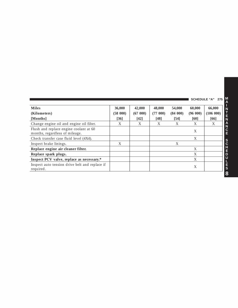
Miles 36,000 42,000 48,000 54,000 60,000 66,000(Kilometers) (58 000) (67 000) (77 000) (84 000) (96 000) (106 000)[Months] [36] [42] [48] [54] [60] [66]Change engine oil and engine oil filter. X X X X X XFlush and replace engine coolant at 60months, regardless of mileage. X
Check transfer case fluid level (4X4). XInspect brake linings. X XReplace engine air cleaner filter. XReplace spark plugs. XInspect PCV valve, replace as necessary.* XInspect auto tension drive belt and replace ifrequired. X
SCHEDULE “A” 275
8
MAINTENANCE
SCHEDULES

Miles 72,000 78,000 84,000 90,000 96,000 100,000(Kilometers) (115 000) (125 000) (134 000) (144000) (154 000) (160 000)[Months] [72] [78] [84] [90] [96]Change engine oil and engine oil filter. X X X X XCheck transfer case fluid Level (4X4). XInspect brake linings. X XReplace engine air cleaner filter. XReplace spark plugs. XInspect PCV valve, replace as necessary.* XInspect auto tension drive belt and replace ifrequired.‡ X
Drain and refill automatic transmission fluidand change main sump and cooler return fil-ter (if equipped) (4.7L).
X
276 SCHEDULE “A”
8
MAINTENANCE
SCHEDULES
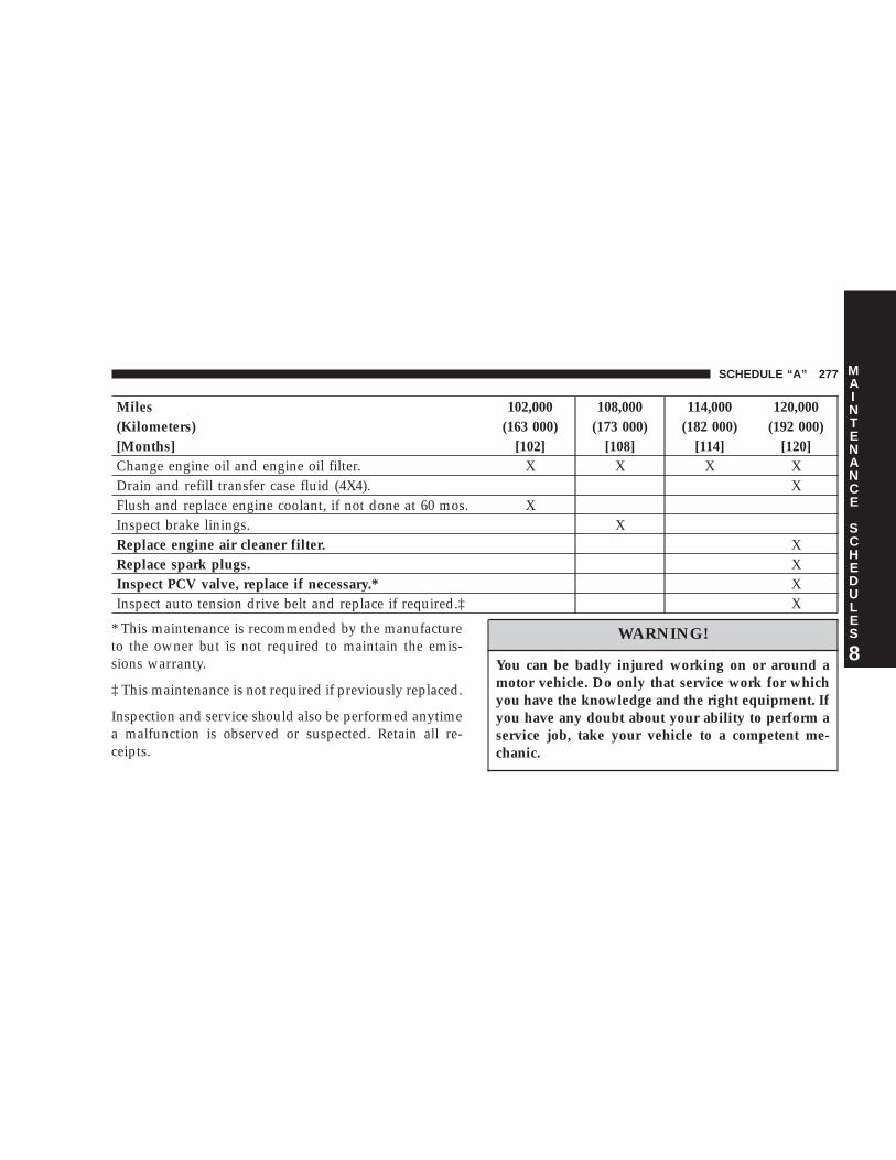
Miles 102,000 108,000 114,000 120,000(Kilometers) (163 000) (173 000) (182 000) (192 000)[Months] [102] [108] [114] [120]Change engine oil and engine oil filter. X X X XDrain and refill transfer case fluid (4X4). XFlush and replace engine coolant, if not done at 60 mos. XInspect brake linings. XReplace engine air cleaner filter. XReplace spark plugs. XInspect PCV valve, replace if necessary.* XInspect auto tension drive belt and replace if required.‡ X
* This maintenance is recommended by the manufactureto the owner but is not required to maintain the emis-sions warranty.
‡ This maintenance is not required if previously replaced.
Inspection and service should also be performed anytimea malfunction is observed or suspected. Retain all re-ceipts.
WARNING!
You can be badly injured working on or around amotor vehicle. Do only that service work for whichyou have the knowledge and the right equipment. Ifyou have any doubt about your ability to perform aservice job, take your vehicle to a competent me-chanic.
SCHEDULE “A” 277
8
MAINTENANCE
SCHEDULES


IF YOU NEED CONSUMER ASSISTANCE
CONTENTS
m Suggestions For Obtaining Service For YourVehicle . . . . . . . . . . . . . . . . . . . . . . . . . . . . . . 280
▫ Prepare For The Appointment . . . . . . . . . . . . 280
▫ Prepare A List . . . . . . . . . . . . . . . . . . . . . . . . 280
▫ Be Reasonable With Requests . . . . . . . . . . . . . 280
m If You Need Assistance . . . . . . . . . . . . . . . . . . 280
m Warranty Information . . . . . . . . . . . . . . . . . . . 282
m Mopart Parts . . . . . . . . . . . . . . . . . . . . . . . . . 284
m Reporting Safety Defects . . . . . . . . . . . . . . . . . 284
▫ In Canada . . . . . . . . . . . . . . . . . . . . . . . . . . 284
m Publication Order Forms . . . . . . . . . . . . . . . . . 284
9

SUGGESTIONS FOR OBTAINING SERVICE FORYOUR VEHICLE
Prepare For The AppointmentIf you’re having warranty work done, be sure to have theright papers with you. Take your warranty folder. Allwork to be performed may not be covered by thewarranty, discuss additional charges with the servicemanager. Keep a maintenance log of your vehicle’sservice history. This can often provide a clue to thecurrent problem.
Prepare A ListMake a written list of your vehicle’s problems or thespecific work you want done. If you’ve had an accident,or work done that is not on your maintenance log, let theservice advisor know.
Be Reasonable With RequestsIf you list a number of items, and you must have yourvehicle by the end of the day, discuss the situation withthe service advisor and list the items in order of priority.At many dealers you may obtain a rental vehicle at a
minimal daily charge. If you need a rental, it is advisableto make these arrangements when you call for an ap-pointment.
IF YOU NEED ASSISTANCEThe manufacturer and its dealers are vitally interested inyour satisfaction. We want you to be happy with ourproducts and services.
Your selling dealer is best equipped and most anxious toprovide prompt resolution for any warranty issue orrelated matter that you may experience. The manufactur-er’s dealers have the facilities, factory-trained techni-cians, special tools, and the latest information to assureyour vehicle is fixed correctly and in a timely manner.The manufacturer has empowered its dealers to makewarranty and repair decisions that ensure you are notinconvenienced. There is no need for you to wait for adecision from the manufacturer. If a special circumstanceoccurs that requires information from the manufacturer,we have asked the dealer’s service management to makethe contact on your behalf.
280 IF YOU NEED CONSUMER ASSISTANCE

This is why you should always talk to your dealer’sservice manager first. Most matters can be resolved withthis process.
• If for some reason you are still not satisfied, talk to thegeneral manager or owner of the dealership. Theywant to know if you need assistance.
• If your dealership is unable to resolve the concern, youmay contact the Manufacturer’s Customer Center.
Any communication to the Manufacturer’s CustomerCenter should include the following information:
• Owner’s name and address
• Owner’s telephone number (home and office)
• Dealership name
• Vehicle identification number
• Vehicle delivery date and mileage
DaimlerChrysler Motors Corporation Customer CenterP.O. Box 21–8004Auburn Hills, MI 48321–8004Phone: (800) 992-1997
DaimlerChrysler Canada Inc. Customer CenterP.O. Box 1621Windsor, Ontario N9A 4H6Phone —(800) 465–2001
In Mexico contact:Av. Prolongacion Paseo de la Reforma, 1240Sante Fe C.P. 05109Mexico, D. F.In Mexico (915) 729–1248 or 729–1240Outside Mexico (525) 729–1248 or 729–1240
Customer Assistance For The Hearing Or SpeechImpaired (TDD/TTY)To assist customers who have hearing difficulties, themanufacturer has installed special TDD (Telecommuni-cation Devices for the Deaf) equipment at its CustomerCenter. Any hearing or speech impaired customer whohas access to a TDD or a conventional teletypewriter(TTY) in the United States can communicate with themanufacturer by dialing 1–800–380–CHRY.
IF YOU NEED CONSUMER ASSISTANCE 281
9

Service ContractYou may have purchased a service contract for yourvehicle to help protect you from the high cost of unex-pected repairs after your manufacturer’s new vehiclelimited warranty expires. The manufacturer stands be-hind only the manufacturer’s Service Contracts. If youpurchased a manufacturer’s Service Contract, you willreceive Plan Provisions and an Owner Identification Cardin the mail within three weeks of your vehicle deliverydate. If you have any questions about your servicecontract, call the manufacturer’s Service Contract Na-tional Customer Hotline at 1-800-521-9922.
The manufacturer will not stand behind any servicecontract that is not the manufacturer’s Service Contract. Itis not responsible for any service contract other than themanufacturer’s Service Contract. If you purchased aservice contract that is not a manufacturer’s ServiceContract, and you require service after your manufactur-er’s new vehicle limited warranty expires, please refer toyour contract documents, and contact the person listed inthose documents.
We appreciate that you have made a major investmentwhen you purchased your new vehicle. Your dealer hasalso made a major investment in facilities, tools, andtraining to assure that you are absolutely delighted withyour ownership experience. You’ll be pleased with theirsincere efforts to resolve any warranty issues or relatedconcerns.
WARRANTY INFORMATIONSee your manufacturer’s Warranty Information Bookletfor information on warranty coverage and transfer ofwarranty.
282 IF YOU NEED CONSUMER ASSISTANCE

IF YOU NEED CONSUMER ASSISTANCE 283
9

MOPART PARTSMopart fluids, lubricants, parts, and accessories areavailable from your dealer. They will help you keep yourvehicle operating at its best.
REPORTING SAFETY DEFECTSIn the 50 United States and Washington D.C.: If youbelieve that your vehicle has a defect which could causea crash or cause injury or death, you should immediatelyinform the National Highway Traffic Safety Administra-tion (NHTSA) in addition to notifying the manufacturer.
If NHTSA receives similar complaints, it may open aninvestigation, and if it finds that a safety defect exists ina group of vehicles, it may order a recall and remedycampaign. However, NHTSA cannot become involved inindividual problems between you, your dealer, and themanufacturer.
To contact NHTSA, you may either call the Auto SafetyHotline toll free at 1-800-424-9393 (or 366-0123 in Wash-ington DC area) or write to: NHTSA, U.S. Dept. of
Transportation, Washington DC 20590. You can alsoobtain other information about motor vehicle safety fromthe Hotline.
In Canada:If you believe that your vehicle has a safety defect, youshould contact the Customer Service Department imme-diately. Canadian customers who wish to report a safetydefect to the Canadian government should write toTransport Canada, Motor Vehicle Defect Investigationsand Recalls, 2780 Sheffield Road, Ottawa, Ontario K1B3V9.
PUBLICATION ORDER FORMSTo order the following manuals, you may use either thewebsite or the phone numbers listed below. Visa, Mas-tercard, American Express, and Discover orders are ac-cepted. If you prefer mailing your payment, please callfor an order form.
NOTE: A street address is required when orderingmanuals. (No P.O. Boxes).
284 IF YOU NEED CONSUMER ASSISTANCE

• Service Manuals.
These comprehensive service manuals provide theinformation that students and professional techniciansneed in diagnosing/troubleshooting, problem solving,maintaining, servicing and repairing DaimlerChryslerCorporation vehicles. A complete working knowledgeof the vehicle, system and/or components is written instraightforward language with illustrations, diagramsand charts.
• Diagnostic Procedure Manuals.
Filled with diagrams, charts and detailed illustrations,these practical manuals make it easy for students andtechnicians to find and fix problems on computer-controlled vehicle systems and features. They showexactly how to find and correct problems the first time,using step-by-step troubleshooting and driveabilityprocedures, proven diagnostic tests and a complete listof all tools and equipment.
• Owner’s Manuals.
These manuals have been prepared with the assistanceof service and engineering specialists to acquaint youwith specific Chrysler group vehicles. Included arestarting, operating, emergency and maintenance pro-cedures as well as specifications, capabilities andsafety tips.
Call Toll Free at 1–800–890–4038 (U.S.) or 1–800–387–1143(Canada)
Or
Visit us on the World Wide Web at:
www.techauthority.daimlerchrysler.com orwww.daimlerchrysler.ca/manuals
IF YOU NEED CONSUMER ASSISTANCE 285
9


INDEX
10

Adding Engine Coolant (Antifreeze) . . . . . . . . . 239Adding Fuel . . . . . . . . . . . . . . . . . . . . . . . . 186,208Air Conditioner Maintenance . . . . . . . . . . . . . . 233Air Conditioning . . . . . . . . . . . . . . . . . . . . . . . 134Air Conditioning, Operating Tips . . . . . . . . 135,137Air Conditioning Refrigerant . . . . . . . . . . . . . . 234Air Conditioning System . . . . . . . . . . . . . . . . . 134Air Pressure, Tires . . . . . . . . . . . . . . . . . . . 176,182Airbag . . . . . . . . . . . . . . . . . . . . . . . . . . . 31,34,102Airbag Light . . . . . . . . . . . . . . . . . . . . . . . . . . . 38Airbag On/Off Switch . . . . . . . . . . . . . . . . . . . . 34Alarm . . . . . . . . . . . . . . . . . . . . . . . . . . . . . 21,102Alarm, Panic . . . . . . . . . . . . . . . . . . . . . . . . . . . 19Alignment and Balance . . . . . . . . . . . . . . . . . . 181Alterations/Modifications, Vehicle . . . . . . . . . . . . 5Antifreeze (Engine Coolant) . . . . . . . . . . . . 238,258Anti-Lock Brake System . . . . . . . . . . . . . . . 164,165Anti-Lock Warning Light . . . . . . . . . . . . . . . . . 102Anti-Theft System . . . . . . . . . . . . . . . . . . . . 21,102Appearance Care . . . . . . . . . . . . . . . . . . . . . . . 249Automatic Dimming Mirror . . . . . . . . . . . . . . . . 59Automatic Transmission . . . . . . . . . . . . 144,146,245
Adding Fluid . . . . . . . . . . . . . . . . . . . . . . . . 246
Fluid and Filter Changes . . . . . . . . . . . . . . . . 247Fluid Level Check . . . . . . . . . . . . . . . . . . . . . 245Fluid Type . . . . . . . . . . . . . . . . . . . . . . . 247,260Gear Ranges . . . . . . . . . . . . . . . . . . . . . . . . . 147Overdrive . . . . . . . . . . . . . . . . . . . . . . . . . . . 148Shifting . . . . . . . . . . . . . . . . . . . . . . . . . . . . 146Special Additives . . . . . . . . . . . . . . . . . . . . . 247Torque Converter . . . . . . . . . . . . . . . . . . . . . 149
Axle Fluid . . . . . . . . . . . . . . . . . . . . . . . . . . . . 260Axle Lubrication . . . . . . . . . . . . . . . . . . . . . . . 248
Backfire, Engine . . . . . . . . . . . . . . . . . . . . . . . . 190Ball Joints . . . . . . . . . . . . . . . . . . . . . . . . . . . . 235Battery . . . . . . . . . . . . . . . . . . . . . . . . . . . . . . . 232
Charging . . . . . . . . . . . . . . . . . . . . . . . . . . . 215Emergency Starting . . . . . . . . . . . . . . . . . . . . 215Gas Caution . . . . . . . . . . . . . . . . . . . . . . . . . 215Keyless Transmitter Replacement . . . . . . . . . . 21Saving Feature . . . . . . . . . . . . . . . . . . . . . . . . 68
Belts, Drive . . . . . . . . . . . . . . . . . . . . . . . . . . . 230Belts, Seat . . . . . . . . . . . . . . . . . . . . . . . . . . . . . 25Body Mechanism Lubrication . . . . . . . . . . . . . . 235B-Pillar Location . . . . . . . . . . . . . . . . . . . . . . . 172
288 INDEX

Brake Fluid . . . . . . . . . . . . . . . . . . . . . . . . . . . 260Brake System . . . . . . . . . . . . . . . . . . . . . . . 164,243
Anti-Lock . . . . . . . . . . . . . . . . . . . . . . . . 164,165Disc Brakes . . . . . . . . . . . . . . . . . . . . . . . . . . 243Fluid Check . . . . . . . . . . . . . . . . . . . . . . . . . 243Hoses . . . . . . . . . . . . . . . . . . . . . . . . . . . . . . 244Master Cylinder . . . . . . . . . . . . . . . . . . . . . . 243Parking . . . . . . . . . . . . . . . . . . . . . . . . . . . . 163Self-Adjusting Rear . . . . . . . . . . . . . . . . . . . . 243Warning Light . . . . . . . . . . . . . . . . . . . . . . . 101
Brake/Transmission Interlock . . . . . . . . . . . . . . 146Break-In Recommendations, New Vehicle . . . . . . 52Bulb Replacement . . . . . . . . . . . . . . . . . . . . . . 255Bulbs, Light . . . . . . . . . . . . . . . . . . . . . . . . . . . 254
Camper . . . . . . . . . . . . . . . . . . . . . . . . . . . . . . . 90Capacities, Fluid . . . . . . . . . . . . . . . . . . . . . . . 258Capacity, Cargo Weight . . . . . . . . . . . . . . . . . . 191Caps, Filler
Fuel . . . . . . . . . . . . . . . . . . . . . . . . . . . . . . . 186Power Steering . . . . . . . . . . . . . . . . . . . . . . . 234
Car Washes . . . . . . . . . . . . . . . . . . . . . . . . . . . 250Carbon Monoxide Warning . . . . . . . . . . . . . 91,189
Cargo . . . . . . . . . . . . . . . . . . . . . . . . . . . . . . . 191Cargo Area Features . . . . . . . . . . . . . . . . . . . . . 194Cargo Light . . . . . . . . . . . . . . . . . . . . . . . . . 70,102Cassette Tape and Player Maintenance . . . . . . . 131Cassette Tape Player . . . . . . . . . . . . . . . 106,119,121Catalytic Converter . . . . . . . . . . . . . . . . . . 189,231CD Changer . . . . . . . . . . . . . . . . . . . . . 113,117,122CD Player . . . . . . . . . . . . . . . . . 110,114,116,124,126Cellular Phone . . . . . . . . . . . . . . . . . . . . . . . . . 132Center High Mounted Stop Light . . . . . . . . . . . 257Center Lap Belts . . . . . . . . . . . . . . . . . . . . . . . . 30Center Seat Storage Compartment . . . . . . . . . . . 89Certification Label . . . . . . . . . . . . . . . . . . . . . . 191Changing A Flat Tire . . . . . . . . . . . . . . . . . . . . 209Charging . . . . . . . . . . . . . . . . . . . . . . . . . . . . . 215Chart, Tire Sizing . . . . . . . . . . . . . . . . . . . . . . . 169Child Restraint . . . . . . . . . . . . . . . . . . . . . 38,39,52Child Restraint Tether Anchors . . . . . . . . . . . 42,46Child Safety Locks . . . . . . . . . . . . . . . . . . . . . . . 16Child Seat . . . . . . . . . . . . . . . . . . . . . . . . . . . . . 45Climate Control . . . . . . . . . . . . . . . . . . . . . . . . 133Clock . . . . . . . . . . . . . . . . . . . . . . . . . . . . . . . . 105Club Cab . . . . . . . . . . . . . . . . . . . . . . . . . . . . 24,64
INDEX 289
10
Compact Disc Maintenance . . . . . . . . . . . . . . . 132Compact Disc Player . . . . . . . . . . . . . . . . . 106,110Compact Spare Tire . . . . . . . . . . . . . . . . . . . . . 178Compass . . . . . . . . . . . . . . . . . . . . . . . . . . . . . . 79Compass Calibration . . . . . . . . . . . . . . . . . . . 79,80Computer, Trip/Travel . . . . . . . . . . . . . . . . . . . . 77Console, Floor . . . . . . . . . . . . . . . . . . . . . . . . . . 88Console, Overhead . . . . . . . . . . . . . . . . . . . . . . . 76Contract, Service . . . . . . . . . . . . . . . . . . . . . . . 282Converter, Catalytic . . . . . . . . . . . . . . . . . . . . . 189Coolant Pressure Cap . . . . . . . . . . . . . . . . . . . . 240Cooling System . . . . . . . . . . . . . . . . . . . . . 237,240
Adding Coolant (Antifreeze) . . . . . . . . . . . . . 239Coolant Capacity . . . . . . . . . . . . . . . . . . . . . 258Coolant Level . . . . . . . . . . . . . . . . . . . . . . . . 240Disposal of Used Coolant . . . . . . . . . . . . . . . 238Drain, Flush, and Refill . . . . . . . . . . . . . . . . . 238Inspection . . . . . . . . . . . . . . . . . . . . . . . . . . . 237Points to Remember . . . . . . . . . . . . . . . . . . . 241Radiator Cap . . . . . . . . . . . . . . . . . . . . . . . . 240Selection of Coolant . . . . . . . . . . . . . 238,258,259Temperature Gauge . . . . . . . . . . . . . . . . . . . . 99
Cruise Control . . . . . . . . . . . . . . . . . . . . . . . . . . 74
Cruise Light . . . . . . . . . . . . . . . . . . . . . . . . . . . 104Cup Holder . . . . . . . . . . . . . . . . . . . . . . . . . . . . 89Customer Assistance . . . . . . . . . . . . . . . . . . . . 280
Daytime Running Lights . . . . . . . . . . . . . . . . . . 69Dealer Service . . . . . . . . . . . . . . . . . . . . . . . . . 225Defroster, Rear Window . . . . . . . . . . . . . . . . . . 140Defroster, Windshield . . . . . . . . . . . . . . . 54,133,136Delay Wipers . . . . . . . . . . . . . . . . . . . . . . . . . . . 71Diagnostic System, Onboard . . . . . . . . . . . . . . . 223Differential, Limited-Slip . . . . . . . . . . . . . . . . . 162Dimmer Switch, Headlight . . . . . . . . . . . . . . . . 100Dipsticks
Automatic Transmission . . . . . . . . . . . . . . . . 245Oil (Engine) . . . . . . . . . . . . . . . . . . . . . . . . . 226Power Steering . . . . . . . . . . . . . . . . . . . . . . . 234
Disabled Vehicle Towing . . . . . . . . . . . . . . . . . 217Disc Brakes . . . . . . . . . . . . . . . . . . . . . . . . . . . 243Disposal
Used Coolant . . . . . . . . . . . . . . . . . . . . . . . . 238Door Ajar . . . . . . . . . . . . . . . . . . . . . . . . . . . . 103Door Locks . . . . . . . . . . . . . . . . . . . . . . . . . . 13,14Door Opener, Garage . . . . . . . . . . . . . . . . . . . . . 81
290 INDEX

Downshifting . . . . . . . . . . . . . . . . . . . . . . . . . . 151Drive Belts . . . . . . . . . . . . . . . . . . . . . . . . . . . . 230Drive Shaft Universal Joints . . . . . . . . . . . . . . . 235
Electrical Power Outlets . . . . . . . . . . . . . . . . . . . 86Electronic Power Distribution Center . . . . . . . . 252Electronic Speed Control . . . . . . . . . . . . . . . . . . 74Emergency, In Case of
Freeing Vehicle When Stuck . . . . . . . . . . . . . 167Jacking . . . . . . . . . . . . . . . . . . . . . . . . . . . . . 211Jump Starting . . . . . . . . . . . . . . . . . . . . . . . . 215Overheating . . . . . . . . . . . . . . . . . . . . . . . . . 239Towing . . . . . . . . . . . . . . . . . . . . . . . . . . . . . 217
Emission Control System Maintenance . . . . . . . 262Emission Related Components . . . . . . . . . . . . . 241Engine
Air Cleaner . . . . . . . . . . . . . . . . . . . . . . . . . . 231Air Cleaner Filter . . . . . . . . . . . . . . . . . . . . . 230Block Heater . . . . . . . . . . . . . . . . . . . . . . . . . 146Break-In Recommendations . . . . . . . . . . . . . . . 52Compartment . . . . . . . . . . . . . . . . . . . . . 221,222Coolant . . . . . . . . . . . . . . . . . . . . . . . . . . 238,259Cooling . . . . . . . . . . . . . . . . . . . . . . . . . . . . 237
Exhaust Gas Caution . . . . . . . . . . . . . . . . 53,189Fails to Start . . . . . . . . . . . . . . . . . . . . . . . . . 145Flooded, Starting . . . . . . . . . . . . . . . . . . . . . 145Fuel Requirements . . . . . . . . . . . . . . . . . . . . 258Oil . . . . . . . . . . . . . . . . . . . . . . . . . . 226,258,259Oil Selection . . . . . . . . . . . . . . . . . . . . . . . . . 258Oil Synthetic . . . . . . . . . . . . . . . . . . . . . . . . . 229Overheating . . . . . . . . . . . . . . . . . . . . . . . . . 239Starting . . . . . . . . . . . . . . . . . . . . . . . . . . . . 144Temperature Gauge . . . . . . . . . . . . . . . . . . . . 99
Entry System, Illuminated . . . . . . . . . . . . . . . . . 12Equipment Identification Plate . . . . . . . . . . . . . 206Exhaust Gas Caution . . . . . . . . . . . . . . . . . . 53,237Exhaust System . . . . . . . . . . . . . . . . . . . . . . 53,236Exterior Lighting . . . . . . . . . . . . . . . . . . . . . . . . 68
FiltersAir Cleaner . . . . . . . . . . . . . . . . . . . . . . . . . . 230Engine Fuel . . . . . . . . . . . . . . . . . . . . . . . . . 231Engine Oil . . . . . . . . . . . . . . . . . . . . . . . 229,259Engine Oil Disposal . . . . . . . . . . . . . . . . . . . 229
FlashersHazard Warning . . . . . . . . . . . . . . . . . . . . . . 208
INDEX 291
10

Turn Signal . . . . . . . . . . . . . . . . . . . . . . . . . . 99Flat Tire Stowage . . . . . . . . . . . . . . . . . . . . . . . 215Flooded Engine Starting . . . . . . . . . . . . . . . . . . 145Floor Console . . . . . . . . . . . . . . . . . . . . . . . . . . 88Fluid, Brake . . . . . . . . . . . . . . . . . . . . . . . . . . . 260Fluid Capacities . . . . . . . . . . . . . . . . . . . . . . . . 258Fluid Level Checks
Automatic Transmission . . . . . . . . . . . . . . . . 245Brake . . . . . . . . . . . . . . . . . . . . . . . . . . . . . . 243Cooling System . . . . . . . . . . . . . . . . . . . . . . . 237Power Steering . . . . . . . . . . . . . . . . . . . . . . . 234Transfer Case . . . . . . . . . . . . . . . . . . . . . . . . 248
Fog Lights . . . . . . . . . . . . . . . . . . . . . . . . . . 69,257Four Wheel Drive . . . . . . . . . . . . . . . . . . . . . . 151
Operation . . . . . . . . . . . . . . . . . . . . . . . . . . . 151Four-Way Hazard Flasher . . . . . . . . . . . . . . . . . 208Freeing A Stuck Vehicle . . . . . . . . . . . . . . . . . . 167Front Axle . . . . . . . . . . . . . . . . . . . . . . . . . . . . 248Fuel . . . . . . . . . . . . . . . . . . . . . . . . . . . . . . . . . 184
Adding . . . . . . . . . . . . . . . . . . . . . . . . . . . . . 186Filler Cap . . . . . . . . . . . . . . . . . . . . . . . . . . . 186Filter . . . . . . . . . . . . . . . . . . . . . . . . . . . . . . 231Gasoline . . . . . . . . . . . . . . . . . . . . . . . . . . . . 184
Gauge . . . . . . . . . . . . . . . . . . . . . . . . . . . . . 100Materials Added . . . . . . . . . . . . . . . . . . . . . . 186Octane Rating . . . . . . . . . . . . . . . . . . . . . . . . 259Requirements . . . . . . . . . . . . . . . . . . . . . 184,258System Hoses . . . . . . . . . . . . . . . . . . . . . . . . 241Tank Capacity . . . . . . . . . . . . . . . . . . . . . . . . 258
Fuses . . . . . . . . . . . . . . . . . . . . . . . . . . . . . . . . 253
Garage Door Opener . . . . . . . . . . . . . . . . . . . . . 81Gasoline . . . . . . . . . . . . . . . . . . . . . . . . . . . . . 184Gasoline, Reformulated . . . . . . . . . . . . . . . . . . 184Gauges
Coolant Temperature . . . . . . . . . . . . . . . . . . . 99Fuel . . . . . . . . . . . . . . . . . . . . . . . . . . . . . . . 100Oil Pressure . . . . . . . . . . . . . . . . . . . . . . . . . 100Speedometer . . . . . . . . . . . . . . . . . . . . . . . . . 100Tachometer . . . . . . . . . . . . . . . . . . . . . . . . . . 99Voltmeter . . . . . . . . . . . . . . . . . . . . . . . . . . . . 99
Gear Ranges . . . . . . . . . . . . . . . . . . . . . . . . 100,147Glass Cleaning . . . . . . . . . . . . . . . . . . . . . . . . . 251GVWR . . . . . . . . . . . . . . . . . . . . . . . . . . . . . . . 191
Hazard Warning Flasher . . . . . . . . . . . . . . . . . . 208
292 INDEX

Headlights . . . . . . . . . . . . . . . . . . . . . . . . . . . . 255Dimmer Switch . . . . . . . . . . . . . . . . . . . . . . . 100High Beam . . . . . . . . . . . . . . . . . . . . . . . . . . . 71High Beam/Low Beam Select Switch . . . . . . . 71Lights On Reminder . . . . . . . . . . . . . . . . . . . . 69Replacing . . . . . . . . . . . . . . . . . . . . . . . . . . . 255Switch . . . . . . . . . . . . . . . . . . . . . . . . . . . . . . 68
Heater . . . . . . . . . . . . . . . . . . . . . . . . . . . . . . . 133Heater, Engine Block . . . . . . . . . . . . . . . . . . . . 146High Beam/Low Beam Select Switch . . . . . . . . . 71Hitches
Trailer Towing . . . . . . . . . . . . . . . . . . . . . . . 198Holder, Cup . . . . . . . . . . . . . . . . . . . . . . . . . . . 89Homelink Transmitter . . . . . . . . . . . . . . . . . . . . 81Hood Release . . . . . . . . . . . . . . . . . . . . . . . . . . 66Hoses . . . . . . . . . . . . . . . . . . . . . . . . . . . . . . . 241
Ignition . . . . . . . . . . . . . . . . . . . . . . . . . . . . . . . 11Cables . . . . . . . . . . . . . . . . . . . . . . . . . . . . . 230Key . . . . . . . . . . . . . . . . . . . . . . . . . . . . . . . 9,11Lock . . . . . . . . . . . . . . . . . . . . . . . . . . . . . . . . 11
Illuminated Entry . . . . . . . . . . . . . . . . . . . . . . . 12Infant Restraint . . . . . . . . . . . . . . . . . . . . . . . 38,39
Inflation Pressure Tires . . . . . . . . . . . . . . . . . . . 182Inside Rearview Mirror . . . . . . . . . . . . . . . . . . . 58Instrument Cluster . . . . . . . . . . . . . . . . . . . . . 97,99Instrument Panel and Controls . . . . . . . . . . . . . . 96Instrument Panel Lens Cleaning . . . . . . . . . . . . 252Interior Appearance Care . . . . . . . . . . . . . . . . . 251Interior Lights . . . . . . . . . . . . . . . . . . . . . . . . . . 67Intermittent Wipers . . . . . . . . . . . . . . . . . . . . . . 71Introduction . . . . . . . . . . . . . . . . . . . . . . . . . . . . 4
Jack Location . . . . . . . . . . . . . . . . . . . . . . . . . . 209Jack Operation . . . . . . . . . . . . . . . . . . . . . . . . . 211Jump Starting . . . . . . . . . . . . . . . . . . . . . . . . . 215
Key, Replacement . . . . . . . . . . . . . . . . . . . . . . . 10Key, Sentry . . . . . . . . . . . . . . . . . . . . . . . . . . . . . 9Key-In Reminder . . . . . . . . . . . . . . . . . . . . . . . . . 9Keyless Entry System . . . . . . . . . . . . . . . . . . . . . 17Keys . . . . . . . . . . . . . . . . . . . . . . . . . . . . . . . . . . 9Knee Bolster . . . . . . . . . . . . . . . . . . . . . . . . . . . 31
Lane Change and Turn Signals . . . . . . . . . . . . 70,99Lap Belts . . . . . . . . . . . . . . . . . . . . . . . . . . . . . . 30
INDEX 293
10

Lap/Shoulder Belts . . . . . . . . . . . . . . . . . . . . . . 25LATCH
(Lower Anchors and Tether for CHildren) . . . . 42Lead Free Gasoline . . . . . . . . . . . . . . . . . . . . . . 184Lights . . . . . . . . . . . . . . . . . . . . . . . . . . . . . . 54,67
Airbag . . . . . . . . . . . . . . . . . . . . . . . . . . . 38,102Anti-Lock Warning . . . . . . . . . . . . . . . . . . . . 102Back-Up . . . . . . . . . . . . . . . . . . . . . . . . . . . . 256Brake Warning . . . . . . . . . . . . . . . . . . . . . . . 101Bulb Replacement . . . . . . . . . . . . . . . . . . . . . 254Cargo . . . . . . . . . . . . . . . . . . . . . . . . . . . . . . . 70Center Mounted Stop . . . . . . . . . . . . . . . . . . 257Check Gauges . . . . . . . . . . . . . . . . . . . . . . . . 101Courtesy/Reading . . . . . . . . . . . . . . . . . . . . . 76Cruise . . . . . . . . . . . . . . . . . . . . . . . . . . . . . 104Daytime Running . . . . . . . . . . . . . . . . . . . . . . 69Fog . . . . . . . . . . . . . . . . . . . . . . . . . . . . . 69,257Hazard Warning Flasher . . . . . . . . . . . . . . . . 208Headlights . . . . . . . . . . . . . . . . . . . . . . . . . . . 68High Beam . . . . . . . . . . . . . . . . . . . . . . . . . . . 71Instrument Cluster . . . . . . . . . . . . . . . . . . . 97,99Intensity Control . . . . . . . . . . . . . . . . . . . . . . 68Interior . . . . . . . . . . . . . . . . . . . . . . . . . . . 67,76
License . . . . . . . . . . . . . . . . . . . . . . . . . . . . . 257Lights On Reminder . . . . . . . . . . . . . . . . . . . . 69Low Fuel . . . . . . . . . . . . . . . . . . . . . . . . . . . 102Low Washer Fluid . . . . . . . . . . . . . . . . . . . . 101Malfunction Indicator . . . . . . . . . . . . . . . . . . 103Park . . . . . . . . . . . . . . . . . . . . . . . . . . . . . . . 256Passing . . . . . . . . . . . . . . . . . . . . . . . . . . . . . 70Seat Belt Reminder . . . . . . . . . . . . . . . . . . . . 101Service . . . . . . . . . . . . . . . . . . . . . . . . . . 254,255Transmission Warning . . . . . . . . . . . . . . . . . . 102Turn Signal . . . . . . . . . . . . . . . . . . . . . . . . 70,256Upshift Indicator . . . . . . . . . . . . . . . . . . . 99,151Warning (Instrument Cluster Description) . . . . 99Washer Fluid . . . . . . . . . . . . . . . . . . . . . . . . 101
Limited-Slip Differential . . . . . . . . . . . . . . . . . . 162Load Limits . . . . . . . . . . . . . . . . . . . . . . . . . . . 191Loading Vehicle . . . . . . . . . . . . . . . . . . . . . 191,194
Tires . . . . . . . . . . . . . . . . . . . . . . . . . . . . . . . 172Locks . . . . . . . . . . . . . . . . . . . . . . . . . . . . . . . . 13
Child Protection . . . . . . . . . . . . . . . . . . . . . . . 16Door . . . . . . . . . . . . . . . . . . . . . . . . . . . . . . . 13Ignition . . . . . . . . . . . . . . . . . . . . . . . . . . . . . 11Keys . . . . . . . . . . . . . . . . . . . . . . . . . . . . . . . . 9
294 INDEX

Power Door . . . . . . . . . . . . . . . . . . . . . . . . . . 14Lower Anchors and Tether for CHildren
(LATCH) . . . . . . . . . . . . . . . . . . . . . . . . . . . . 42Lubricating Oil . . . . . . . . . . . . . . . . . . . . . . . . 248Lubrication, Body . . . . . . . . . . . . . . . . . . . . . . . 235Lug Nuts . . . . . . . . . . . . . . . . . . . . . . . . . . . . . 213Lumbar Support . . . . . . . . . . . . . . . . . . . . . . . . 63
Maintenance . . . . . . . . . . . . . . . . . . . . . . . . . . 226Maintenance Free Battery . . . . . . . . . . . . . . . . . 232Maintenance Procedures . . . . . . . . . . . . . . . . . . 226Maintenance Schedule . . . . . . . . . . . . . . . . . . . 263
Schedule 9A9 . . . . . . . . . . . . . . . . . . . . . . . . . 274Schedule 9B9 . . . . . . . . . . . . . . . . . . . . . . . . . 265
Malfunction Indicator Light . . . . . . . . . . . . 103,224Manual, Service . . . . . . . . . . . . . . . . . . . . . . . . 284Manual Transmission . . . . . . . . . . . . . . 144,150,245
Fluid Level Check . . . . . . . . . . . . . . . . . . . . . 245Lubricant Selection . . . . . . . . . . . . . . . . . 245,260Shift Speeds . . . . . . . . . . . . . . . . . . . . . . . . . 151
Mirrors . . . . . . . . . . . . . . . . . . . . . . . . . . . . . . . 58Automatic Dimming . . . . . . . . . . . . . . . . . . . . 59Electric Powered . . . . . . . . . . . . . . . . . . . . . . . 60
Outside . . . . . . . . . . . . . . . . . . . . . . . . . . . . . 59Rearview . . . . . . . . . . . . . . . . . . . . . . . . . . . . 58
Modifications/Alterations, Vehicle . . . . . . . . . . . . 5Mopar Parts . . . . . . . . . . . . . . . . . . . . . . . . 225,284Multi-Function Control Lever . . . . . . . . . . . . . . . 70
New Vehicle Break-In Period . . . . . . . . . . . . . . . 52
Occupant Restraints . . . . . . . . . . . . . . . . . . . . . . 24Odometer . . . . . . . . . . . . . . . . . . . . . . . . . . . . 103
Trip . . . . . . . . . . . . . . . . . . . . . . . . . . . . . . . 103Oil, Engine . . . . . . . . . . . . . . . . . . . . . . . . . 226,259
Capacity . . . . . . . . . . . . . . . . . . . . . . . . . . . . 258Change Interval . . . . . . . . . . . . . . . . . . . . . . 227Dipstick . . . . . . . . . . . . . . . . . . . . . . . . . . . . 226Disposal . . . . . . . . . . . . . . . . . . . . . . . . . . . . 229Filter . . . . . . . . . . . . . . . . . . . . . . . . . . . 229,259Filter Disposal . . . . . . . . . . . . . . . . . . . . . . . 229Identification Logo . . . . . . . . . . . . . . . . . . . . 228Materials Added to . . . . . . . . . . . . . . . . . . . . 229Pressure Gauge . . . . . . . . . . . . . . . . . . . . . . . 100Recommendation . . . . . . . . . . . . . . . . . . 228,258Synthetic . . . . . . . . . . . . . . . . . . . . . . . . . . . 229
INDEX 295
10

Viscosity . . . . . . . . . . . . . . . . . . . . . . . . . 228,258Onboard Diagnostic System . . . . . . . . . . . . 223,224Opener, Garage Door . . . . . . . . . . . . . . . . . . . . . 81Outside Rearview Mirrors . . . . . . . . . . . . . . . . . 59Overdrive . . . . . . . . . . . . . . . . . . . . . . . . . . . . 148Overhead Console . . . . . . . . . . . . . . . . . . . . . 76,77Overhead Travel Information Center . . . . . . . . . 77Overheating, Engine . . . . . . . . . . . . . . . . . . 104,239Owner’s Manual . . . . . . . . . . . . . . . . . . . . . . . 284
Panic Alarm . . . . . . . . . . . . . . . . . . . . . . . . . . . 19Parking Brake . . . . . . . . . . . . . . . . . . . . . . . . . 163Parking On Hill . . . . . . . . . . . . . . . . . . . . . . . . 163Passenger Airbag On/Off Switch . . . . . . . . . . . . 34Passing Light . . . . . . . . . . . . . . . . . . . . . . . . . . . 70Pickup Box . . . . . . . . . . . . . . . . . . . . . . . . . . . 194Placard, Tire and Loading Information . . . . . . . 172Positive Crankcase Valve . . . . . . . . . . . . . . . . . 242Power
Brakes . . . . . . . . . . . . . . . . . . . . . . . . . . . . . 243Distribution Center . . . . . . . . . . . . . . . . . . . . 252Door Locks . . . . . . . . . . . . . . . . . . . . . . . . . . 14Mirrors . . . . . . . . . . . . . . . . . . . . . . . . . . . . . 60
Outlet . . . . . . . . . . . . . . . . . . . . . . . . . . . . . . 86Steering . . . . . . . . . . . . . . . . . . . . . . . . . 166,234Windows . . . . . . . . . . . . . . . . . . . . . . . . . . . . 22
Power Steering Fluid . . . . . . . . . . . . . . . . . . . . 260Pregnant Women and Seat Belts . . . . . . . . . . . . . 30Pressure Gauge, Oil . . . . . . . . . . . . . . . . . . . . . 100Programmable Electronic Features . . . . . . . . . 82,85Programming Transmitters . . . . . . . . . . . . 19,82,85
Quad Cab . . . . . . . . . . . . . . . . . . . . . . . . . . . . . 65
Radial Ply Tires . . . . . . . . . . . . . . . . . . . . . . . . 178Radiator Cap . . . . . . . . . . . . . . . . . . . . . . . . . . 240Radio . . . . . . . . . . . . . . . . . . . . . . . 106,114,119,124Radio Operation . . . . . . . . . . . . . . . . . . 114,119,132Rear Axle . . . . . . . . . . . . . . . . . . . . . . . . . . . . . 248Rear Window Defroster . . . . . . . . . . . . . . . . . . 140Rearview Mirrors . . . . . . . . . . . . . . . . . . . . . . . . 58Reclining Front Seats . . . . . . . . . . . . . . . . . . . . . 62Recommended Fluids, Lubricants and Genuine
Parts . . . . . . . . . . . . . . . . . . . . . . . . . . . . . . . 259Recreational Towing . . . . . . . . . . . . . . . . . . . . . 202
Shifting into Transfer Case Neutral (N) . . . . . 202
296 INDEX

Shifting out of Transfer Case Neutral (N) . . . 204Reformulated Gasoline . . . . . . . . . . . . . . . . . . . 184Refrigerant . . . . . . . . . . . . . . . . . . . . . . . . . . . . 234Release, Hood . . . . . . . . . . . . . . . . . . . . . . . . . . 66Remote Keyless Entry . . . . . . . . . . . . . . . . . . . . 17Remote Sound System Controls . . . . . . . . . . . . 130Replacement Tires . . . . . . . . . . . . . . . . . . . . . . 180Reporting Safety Defects . . . . . . . . . . . . . . . . . 284Restraints, Child . . . . . . . . . . . . . . . . . . . . . . 38,45Restraints, Occupant . . . . . . . . . . . . . . . . . . . . . 24Rocking Vehicle When Stuck . . . . . . . . . . . . . . 167Rotation, Tires . . . . . . . . . . . . . . . . . . . . . . 183,264
Safety Checks Inside Vehicle . . . . . . . . . . . . . . . 54Safety Checks Outside Vehicle . . . . . . . . . . . . . . 54Safety Defects, Reporting . . . . . . . . . . . . . . . . . 284Safety Information, Tire . . . . . . . . . . . . . . . . . . 167Safety Tips . . . . . . . . . . . . . . . . . . . . . . . . . . . . . 53Schedule, Maintenance . . . . . . . . . . . . . . . . . . . 263Seat Belt Maintenance . . . . . . . . . . . . . . . . . . . 252Seat Belts . . . . . . . . . . . . . . . . . . . . . . . . . . . . 24,25
And Pregnant Women . . . . . . . . . . . . . . . . . . 30Child Restraint . . . . . . . . . . . . . . . . . . . . . . 38,52
Extender . . . . . . . . . . . . . . . . . . . . . . . . . . . . 31Front Seat . . . . . . . . . . . . . . . . . . . . . . . . . . . . 25Inspection . . . . . . . . . . . . . . . . . . . . . . . . . . . 54Reminder . . . . . . . . . . . . . . . . . . . . . . . . . . . 101
Seats . . . . . . . . . . . . . . . . . . . . . . . . . . . . . . . . . 61Adjustment . . . . . . . . . . . . . . . . . . . . . . . . . . 61Bench . . . . . . . . . . . . . . . . . . . . . . . . . . . . . . . 63Easy Entry . . . . . . . . . . . . . . . . . . . . . . . . . . . 64Lumbar Support . . . . . . . . . . . . . . . . . . . . . . . 63Reclining . . . . . . . . . . . . . . . . . . . . . . . . . . . . 62
Security Alarm . . . . . . . . . . . . . . . . . . . . . . . 21,102Selection of Coolant . . . . . . . . . . . . . . . . . . . . . 259Selection of Oil . . . . . . . . . . . . . . . . . . . . . . . . 228Self-Adjusting Brakes . . . . . . . . . . . . . . . . . . . . 243Sentry Key . . . . . . . . . . . . . . . . . . . . . . . . . . . . . 9Service and Maintenance . . . . . . . . . . . . . . 262,263Service Assistance . . . . . . . . . . . . . . . . . . . . . . 280Service Contract . . . . . . . . . . . . . . . . . . . . . . . . 282Service Manuals . . . . . . . . . . . . . . . . . . . . . . . . 284Setting the Clock . . . . . . . . . . . . . . . . . . . . . . . 105Shift Speeds, Manual Transmission . . . . . . . . . . 151Shifting . . . . . . . . . . . . . . . . . . . . . . . . . . . . . . 146
Manual Transmission . . . . . . . . . . . . . . . . . . 150
INDEX 297
10

Transfer Case . . . . . . . . . . . . . . . . . . . . . . . . 151Transfer Case, Shifting into Transfer
Case Neutral (N) . . . . . . . . . . . . . . . . . . . . 202Transfer Case, Shifting out of Transfer
Case Neutral (N) . . . . . . . . . . . . . . . . . . . . 204Shoulder Belt Upper Anchorage . . . . . . . . . . . . . 29Signals, Turn . . . . . . . . . . . . . . . . . . . . . . 70,99,256Sliding Rear Window . . . . . . . . . . . . . . . . . . . . . 23Snow Chains . . . . . . . . . . . . . . . . . . . . . . . . . . 182Snow Plow . . . . . . . . . . . . . . . . . . . . . . . . . . . 201Snow Tires . . . . . . . . . . . . . . . . . . . . . . . . . . . . 183Spare Tire . . . . . . . . . . . . . . . . . . . . . . . . . . . . 210Spark Plugs . . . . . . . . . . . . . . . . . . . . . . . . . . . 230Specifications
Fuel . . . . . . . . . . . . . . . . . . . . . . . . . . . . . . . 184Speed Control . . . . . . . . . . . . . . . . . . . . . . . . . . 74Speedometer . . . . . . . . . . . . . . . . . . . . . . . . . . 100Starting . . . . . . . . . . . . . . . . . . . . . . . . . . . . . . 144
Emergency (Jump Starting) . . . . . . . . . . . . . . 215Engine Block Heater . . . . . . . . . . . . . . . . . . . 146
SteeringColumn Controls . . . . . . . . . . . . . . . . . . . . . . 70Column Lock . . . . . . . . . . . . . . . . . . . . . . . . . 11
Linkage . . . . . . . . . . . . . . . . . . . . . . . . . . . . 235Power . . . . . . . . . . . . . . . . . . . . . . . . . . . 166,234Wheel, Tilt . . . . . . . . . . . . . . . . . . . . . . . . . . . 73
Steering Wheel Mounted Sound SystemControls . . . . . . . . . . . . . . . . . . . . . . . . . . . . 130
Storage Compartment, Center Seat . . . . . . . . . . . 89Storage, Vehicle . . . . . . . . . . . . . . . . . . . . . . . . 254Stuck, Freeing . . . . . . . . . . . . . . . . . . . . . . . . . 167Supplemental Tire Pressure Information . . . . . . 182Synthetic Engine Oil . . . . . . . . . . . . . . . . . . . . . 229
Tachometer . . . . . . . . . . . . . . . . . . . . . . . . . . . . 99Tailgate . . . . . . . . . . . . . . . . . . . . . . . . . . . . . . . 90Taillights . . . . . . . . . . . . . . . . . . . . . . . . . . . . . 256Tape Player . . . . . . . . . . . . . . . . . . . . . . . . . . . 131Temperature Gauge, Engine Coolant . . . . . . . . . 99Tether Anchor, Child Restraint . . . . . . . . . . . . . . 42Thermostat . . . . . . . . . . . . . . . . . . . . . . . . . . . 241Tilt Steering Column . . . . . . . . . . . . . . . . . . . . . 73Tire and Loading Information Placard . . . . . 172,182Tire Identification Number (TIN) . . . . . . . . . . . 171Tire Markings . . . . . . . . . . . . . . . . . . . . . . . . . 167Tire Safety Information . . . . . . . . . . . . . . . . . . . 167
298 INDEX

Tires . . . . . . . . . . . . . . . . . . . . . . . . . . . . . . 54,175Air Pressure . . . . . . . . . . . . . . . . . . . . . . . . . 175Alignment . . . . . . . . . . . . . . . . . . . . . . . . . . 181Chains . . . . . . . . . . . . . . . . . . . . . . . . . . . . . 182Changing . . . . . . . . . . . . . . . . . . . . . . . . . . . 209Compact Spare . . . . . . . . . . . . . . . . . . . . . . . 178General Information . . . . . . . . . . . . . . . . . . . 175High Speed . . . . . . . . . . . . . . . . . . . . . . . . . 177Inflation Pressures . . . . . . . . . . . . . . . . . . . . 176Jacking . . . . . . . . . . . . . . . . . . . . . . . . . . . . . 211Load Capacity . . . . . . . . . . . . . . . . . . . . . . . 172Radial . . . . . . . . . . . . . . . . . . . . . . . . . . . . . 178Replacement . . . . . . . . . . . . . . . . . . . . . . . . . 180Rotation . . . . . . . . . . . . . . . . . . . . . . . . . 183,264Safety . . . . . . . . . . . . . . . . . . . . . . . . . . . 167,175Sizes . . . . . . . . . . . . . . . . . . . . . . . . . . . . . . . 169Snow Tires . . . . . . . . . . . . . . . . . . . . . . . . . . 183Spare Tire . . . . . . . . . . . . . . . . . . . . . . . . . . . 210Spinning . . . . . . . . . . . . . . . . . . . . . . . . . . . . 179Tread Wear Indicators . . . . . . . . . . . . . . . . . . 180Warnings . . . . . . . . . . . . . . . . . . . . . . . . . . . 182Wheel Nut Torque . . . . . . . . . . . . . . . . . . . . 213
Tongue Weight/Trailer Weight . . . . . . . . . . . . . 197
Torque Converter Clutch . . . . . . . . . . . . . . . . . 149Towing
Disabled Vehicle . . . . . . . . . . . . . . . . . . . . . . 217Guide . . . . . . . . . . . . . . . . . . . . . . . . . . . . . . 199Recreational . . . . . . . . . . . . . . . . . . . . . . . . . 202Trailering . . . . . . . . . . . . . . . . . . . . . . . . . . . 195Weight . . . . . . . . . . . . . . . . . . . . . . . . . . . . . 199
Traction . . . . . . . . . . . . . . . . . . . . . . . . . . . . . . 206Trailer Towing . . . . . . . . . . . . . . . . . . . . . . . . . 195
Cooling System Tips . . . . . . . . . . . . . . . . . . . 201Hitches . . . . . . . . . . . . . . . . . . . . . . . . . . . . . 198Minimum Requirements . . . . . . . . . . . . . . . . 199Trailer and Tongue Weight . . . . . . . . . . . . . . 197Wiring . . . . . . . . . . . . . . . . . . . . . . . . . . . . . 200
Trailer Towing Guide . . . . . . . . . . . . . . . . . . . . 199Trailer Weight . . . . . . . . . . . . . . . . . . . . . . . . . 199Transfer Case . . . . . . . . . . . . . . . . . . . . . . . . . . 248
Fluid . . . . . . . . . . . . . . . . . . . . . . . . . . . . . . 260Transmission . . . . . . . . . . . . . . . . . . . . 146,150,245
Automatic . . . . . . . . . . . . . . . . . . . . . 144,146,245Filter . . . . . . . . . . . . . . . . . . . . . . . . . . . . . . 247Fluid . . . . . . . . . . . . . . . . . . . . . . . . 245,247,260Manual . . . . . . . . . . . . . . . . . . . . . . . 144,150,245
INDEX 299
10

Transmitter Battery Service . . . . . . . . . . . . . . . . 21Transmitter, Garage Door Opener . . . . . . . . . . . . 81Transmitter Programming . . . . . . . . . . . . . . . . . 19Tread Wear Indicators . . . . . . . . . . . . . . . . . . . 180Trip Computer . . . . . . . . . . . . . . . . . . . . . . . . . . 77Trip Odometer . . . . . . . . . . . . . . . . . . . . . . . . . 103Turn Signals . . . . . . . . . . . . . . . . . . . 70,99,255,256
Universal Transmitter . . . . . . . . . . . . . . . . . . . . 81Unleaded Gasoline . . . . . . . . . . . . . . . . . . . . . . 184
Vehicle Identification Number . . . . . . . . . . . . . . . 5Vehicle Loading . . . . . . . . . . . . . . . . . . 172,191,194Vehicle Modifications/Alterations . . . . . . . . . . . . 5Vehicle Storage . . . . . . . . . . . . . . . . . . . . . . . . . 254Vented Quarter Window . . . . . . . . . . . . . . . . . . 24Voltmeter . . . . . . . . . . . . . . . . . . . . . . . . . . . . . . 99
Warning Lights (Instrument Cluster Description) . 99Warnings and Cautions . . . . . . . . . . . . . . . . . . . . 5Warranty Information . . . . . . . . . . . . . . . . . . . . 282
Washers, Windshield . . . . . . . . . . . . . . . . . . . . . 72Washing Vehicle . . . . . . . . . . . . . . . . . . . . . . . . 250Weight Load Carrying . . . . . . . . . . . . . . . . . . . 191Wheel Alignment and Balance . . . . . . . . . . . . . 181Wheel and Wheel Trim . . . . . . . . . . . . . . . . . . . 250Wheel Changing . . . . . . . . . . . . . . . . . . . . . . . 209Wheel Nut Torque . . . . . . . . . . . . . . . . . . . . . . 213Wind Buffeting . . . . . . . . . . . . . . . . . . . . . . . . . 24Window Fogging . . . . . . . . . . . . . . . . . . . . . . . 137Windows . . . . . . . . . . . . . . . . . . . . . . . . . . . . . . 22
Power . . . . . . . . . . . . . . . . . . . . . . . . . . . . . . 22Rear Sliding . . . . . . . . . . . . . . . . . . . . . . . . . . 23Vented Quarter . . . . . . . . . . . . . . . . . . . . . . . . 24
Windshield Defroster . . . . . . . . . . . . . . . 54,133,136Windshield Washers . . . . . . . . . . . . . . . . 71,72,236
Fluid . . . . . . . . . . . . . . . . . . . . . . . . . . . . 71,236Windshield Wiper Blades . . . . . . . . . . . . . . . . . 235Windshield Wipers . . . . . . . . . . . . . . . . . . . . . . 71Wiper Blade Replacement . . . . . . . . . . . . . . . . . 235Wipers, Intermittent . . . . . . . . . . . . . . . . . . . . . . 71Wrecker Towing . . . . . . . . . . . . . . . . . . . . . . . . 217
300 INDEX