table of contents: page - defa
TRANSCRIPT
Product DEFA WarmUp kit
Components See table below
Difficulty B
Note: Difficulty stated above reflects the minimum level of expertise required to install the accessory
(A) Customer (B) Dealer Technician (C) Master Technician
Table of contents: Page:
WarmUp Kit - Futura
-Cord set 5
-Termini cable 10
-Futura wiring harness 10
-In-Car Control Unit - Futura 15
-Termini interior heater 19
-Battery charger wiring harness 21
-Onboard battery charger 22
WarmUp Kit - Bluetooth
-Cord set 5
-Termini cable 13
-Bluetooth wiring harness 17
-Bluetooth Control Unit 17
-Termini interior heater 19
-Battery charger wiring harness 21
-Onboard battery charger 22
Engine Heater Kit 23
Cord set 5
On Board Battery Charger Kit
-Cord set 5
-Battery charger wiring harness 21
-Onboard battery charger 22
Cabin Heater Kit
-Cord set 5
-Termini cable 13
-Termini interior heater 19
WarmUp System = WarmUp Kit + Engine Heater Kit
Notes to the Installer: 1) Read the entire installation pamphlet prior to beginning the installation of this accessory.
2) Ensure OEM fasteners that require removal and reinstallation are torqued to specifications
3) Avoid contact between the installed cables and any sharp or moving parts
4) Ensure the vehicle is properly protected in the area(s) where the accessory is to be installed.
5) To prevent vehicle damage, never place tools on top of painted surfaces, seats, dash pad, console or floor carpet/mats.
6) Always wear appropriate safety gear to include gloves and eye protection when required.
Special notes to consider when working on Hybrid vehicles: 1) Always isolate the high voltage battery as directed in the manufacturer’s instructions when working on the vehicle electrical system.
2) Do not secure any DEFA components or cables to any or near any components of the Hybrid drive electrical system.
3) Follow this installation guide to ensure the correct routing of all DEFA system cables.
4) Always wear appropriate safety gear to include gloves and eye protection when required.
5) Always follow manufacturer’s guidelines regarding safe work practices when working on Hybrid vehicles.
TECHNICAL INFORMATION
DEFA North America Inc., 15 Allstate Parkway, Markham, ON, L3R 5B4 1 888 539-DEFA (3332) or 1 647 660-DEFA (3332)
4/13/2021 TD 21007 All Makes WUP 120V CAEN.docx - 2 -
Instructional Symbols / Definitions
Denotes danger of serious physical injury or death
Denotes warning that may lead to serious physical injury or vehicle damage
Denotes cautions to be taken to avoid physical injury or component damage.
Denotes cautions to be taken to avoid vehicle and component damage.
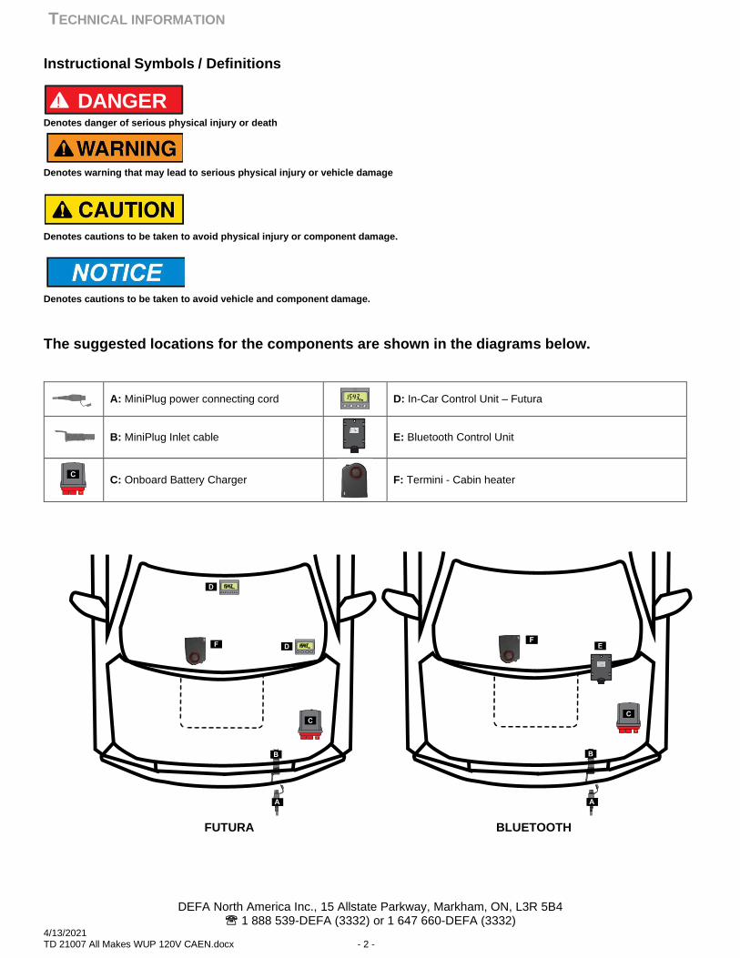
The suggested locations for the components are shown in the diagrams below.
FUTURA BLUETOOTH
! DANGER
A: MiniPlug power connecting cord
D: In-Car Control Unit – Futura
B: MiniPlug Inlet cable
E: Bluetooth Control Unit
C: Onboard Battery Charger
F: Termini - Cabin heater
TECHNICAL INFORMATION
DEFA North America Inc., 15 Allstate Parkway, Markham, ON, L3R 5B4 1 888 539-DEFA (3332) or 1 647 660-DEFA (3332)
4/13/2021 TD 21007 All Makes WUP 120V CAEN.docx - 3 -
READ ALL THE INSTRUCTIONS BEFORE PROCEEDING WITH THE
INSTALLATIONS AS PROCEEDURES MAY OVERLAP.
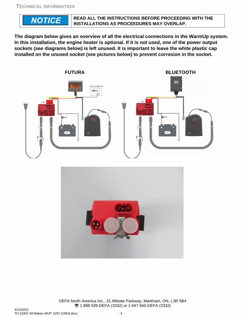
The diagram below gives an overview of all the electrical connections in the WarmUp system.
In this installation, the engine heater is optional. If it is not used, one of the power output
sockets (see diagrams below) is left unused. It is important to leave the white plastic cap
installed on the unused socket (see pictures below) to prevent corrosion in the socket.
FUTURA BLUETOOTH
TECHNICAL INFORMATION
DEFA North America Inc., 15 Allstate Parkway, Markham, ON, L3R 5B4 1 888 539-DEFA (3332) or 1 647 660-DEFA (3332)
4/13/2021 TD 21007 All Makes WUP 120V CAEN.docx - 4 -
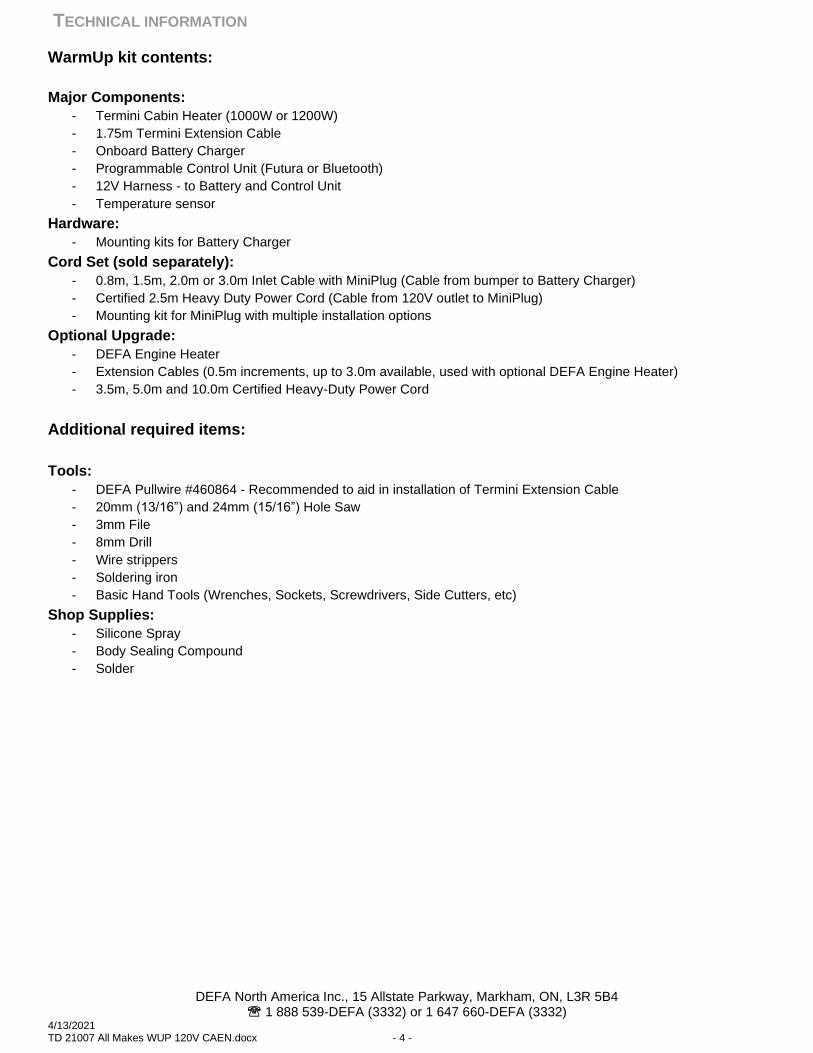
WarmUp kit contents:
Major Components:
- Termini Cabin Heater (1000W or 1200W)
- 1.75m Termini Extension Cable
- Onboard Battery Charger
- Programmable Control Unit (Futura or Bluetooth)
- 12V Harness - to Battery and Control Unit
- Temperature sensor
Hardware:
- Mounting kits for Battery Charger
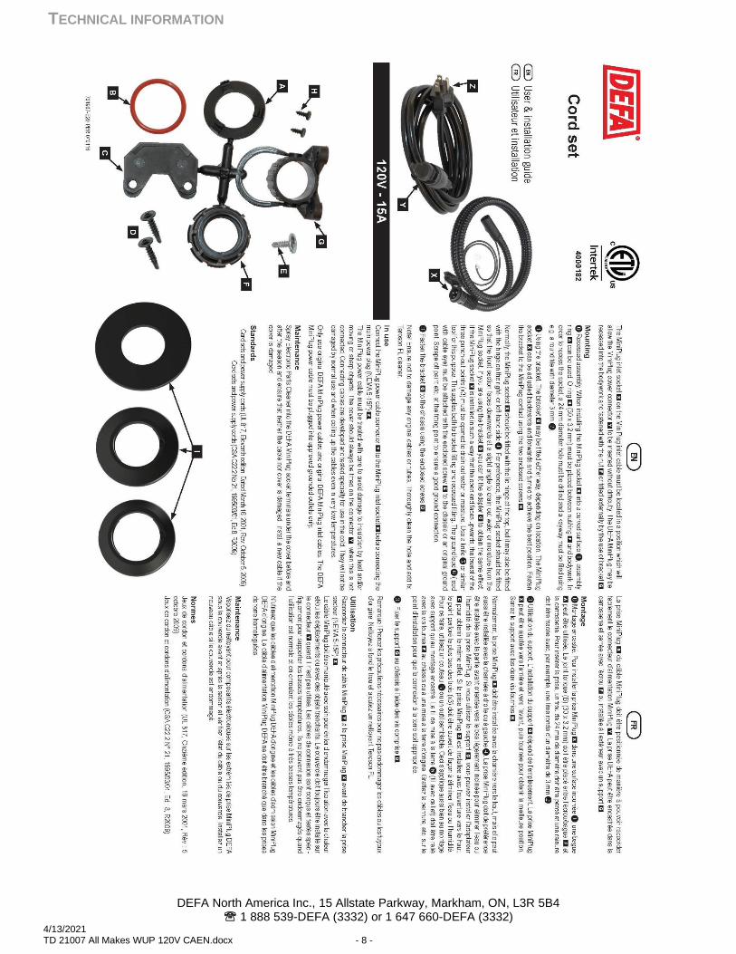
Cord Set (sold separately):
- 0.8m, 1.5m, 2.0m or 3.0m Inlet Cable with MiniPlug (Cable from bumper to Battery Charger)
- Certified 2.5m Heavy Duty Power Cord (Cable from 120V outlet to MiniPlug)
- Mounting kit for MiniPlug with multiple installation options
Optional Upgrade:
- DEFA Engine Heater
- Extension Cables (0.5m increments, up to 3.0m available, used with optional DEFA Engine Heater)
- 3.5m, 5.0m and 10.0m Certified Heavy-Duty Power Cord
Additional required items:
Tools:
- DEFA Pullwire #460864 - Recommended to aid in installation of Termini Extension Cable
- 20mm (13/16”) and 24mm (15/16”) Hole Saw
- 3mm File
- 8mm Drill
- Wire strippers
- Soldering iron
- Basic Hand Tools (Wrenches, Sockets, Screwdrivers, Side Cutters, etc)
Shop Supplies:
- Silicone Spray
- Body Sealing Compound
- Solder
TECHNICAL INFORMATION
DEFA North America Inc., 15 Allstate Parkway, Markham, ON, L3R 5B4 1 888 539-DEFA (3332) or 1 647 660-DEFA (3332)
4/13/2021 TD 21007 All Makes WUP 120V CAEN.docx - 5 -
Inlet cable installation:
HYBRID VEHICLES: Disconnect the high voltage system following the
manufacturers’ service procedures.
READ ALL THE INSTRUCTIONS BEFORE PROCEEDING WITH THE
INSTALLATION. Failure to do so can result in personal injury and/or
damage to vehicle systems.
Avoid contact between the installed cables to any sharp or moving parts.
Failure to do so can result in personal injury and/or damage to vehicle
systems.
Ensure OEM fasteners that require removal and reinstallation are torqued
to specifications. Failure to do so can result in damage to the vehicle
and/or the DEFA system components.
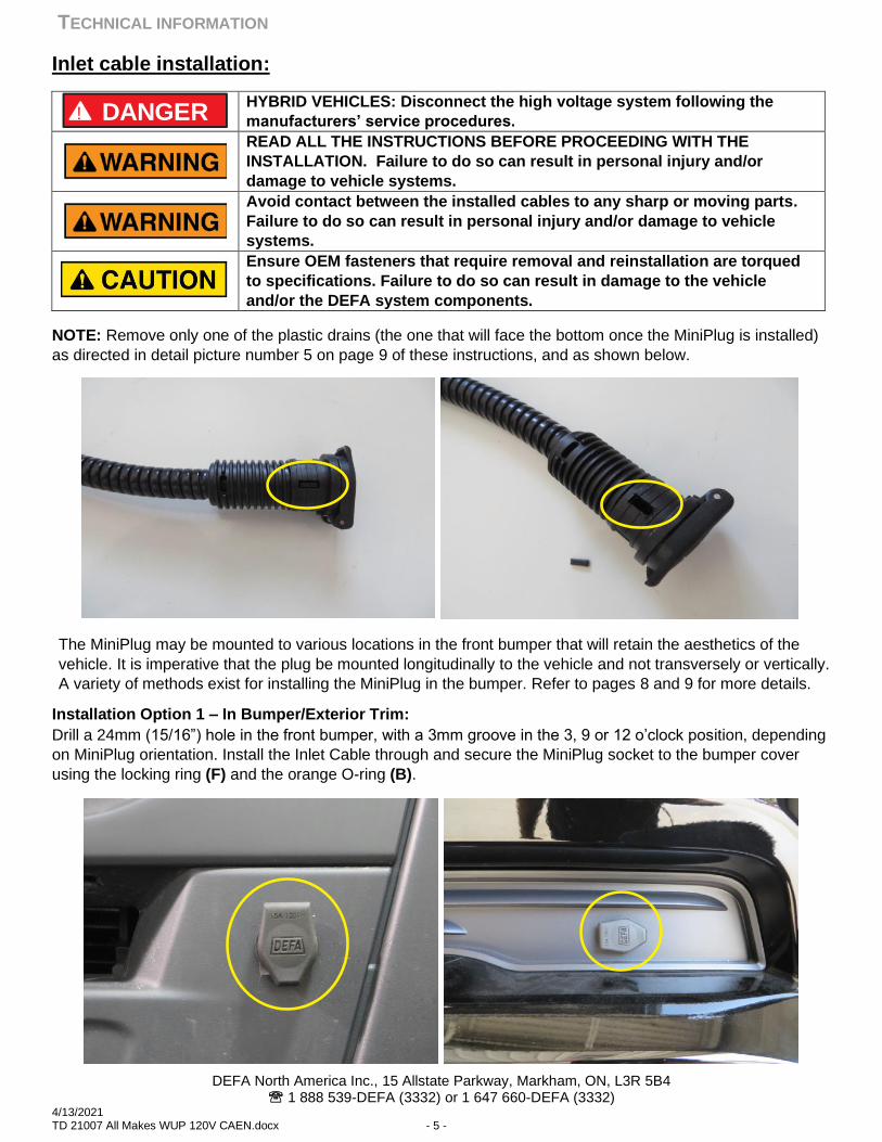
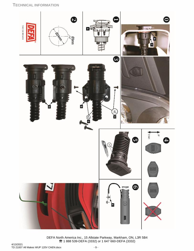
NOTE: Remove only one of the plastic drains (the one that will face the bottom once the MiniPlug is installed)
as directed in detail picture number 5 on page 9 of these instructions, and as shown below.
The MiniPlug may be mounted to various locations in the front bumper that will retain the aesthetics of the
vehicle. It is imperative that the plug be mounted longitudinally to the vehicle and not transversely or vertically.
A variety of methods exist for installing the MiniPlug in the bumper. Refer to pages 8 and 9 for more details.
Installation Option 1 – In Bumper/Exterior Trim:
Drill a 24mm (15/16”) hole in the front bumper, with a 3mm groove in the 3, 9 or 12 o’clock position, depending
on MiniPlug orientation. Install the Inlet Cable through and secure the MiniPlug socket to the bumper cover
using the locking ring (F) and the orange O-ring (B).
! DANGER
TECHNICAL INFORMATION
DEFA North America Inc., 15 Allstate Parkway, Markham, ON, L3R 5B4 1 888 539-DEFA (3332) or 1 647 660-DEFA (3332)
4/13/2021 TD 21007 All Makes WUP 120V CAEN.docx - 6 -
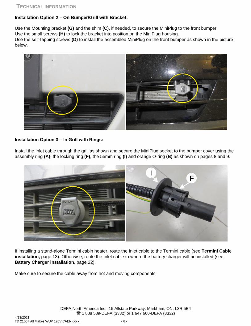
Installation Option 2 – On Bumper/Grill with Bracket:
Use the Mounting bracket (G) and the shim (C), if needed, to secure the MiniPlug to the front bumper.
Use the small screws (H) to lock the bracket into position on the MiniPlug housing.
Use the self-tapping screws (D) to install the assembled MiniPlug on the front bumper as shown in the picture
below.
Installation Option 3 – In Grill with Rings:
Install the Inlet cable through the grill as shown and secure the MiniPlug socket to the bumper cover using the
assembly ring (A), the locking ring (F), the 55mm ring (I) and orange O-ring (B) as shown on pages 8 and 9.
If installing a stand-alone Termini cabin heater, route the Inlet cable to the Termini cable (see Termini Cable
installation, page 13). Otherwise, route the Inlet cable to where the battery charger will be installed (see
Battery Charger installation, page 22).
Make sure to secure the cable away from hot and moving components.
FI
TECHNICAL INFORMATION
DEFA North America Inc., 15 Allstate Parkway, Markham, ON, L3R 5B4 1 888 539-DEFA (3332) or 1 647 660-DEFA (3332)
4/13/2021 TD 21007 All Makes WUP 120V CAEN.docx - 7 -
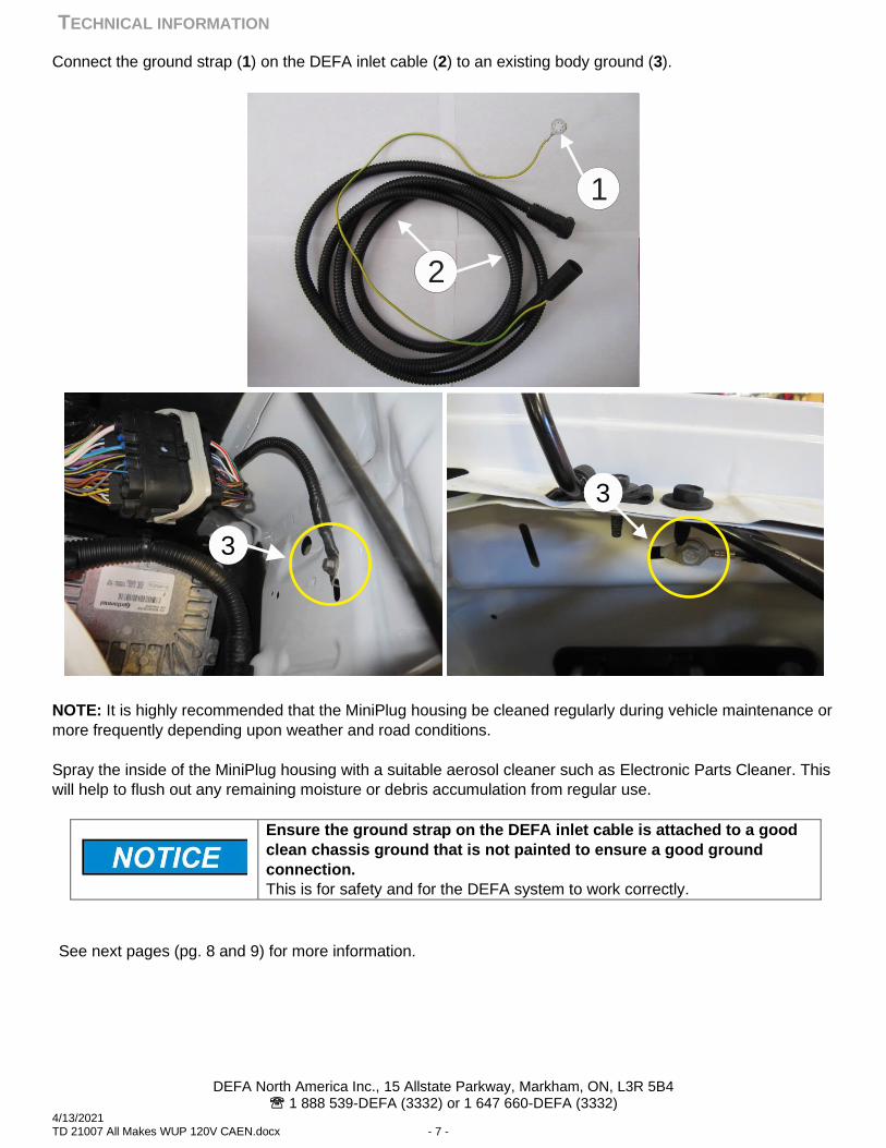
Connect the ground strap (1) on the DEFA inlet cable (2) to an existing body ground (3).
NOTE: It is highly recommended that the MiniPlug housing be cleaned regularly during vehicle maintenance or
more frequently depending upon weather and road conditions.
Spray the inside of the MiniPlug housing with a suitable aerosol cleaner such as Electronic Parts Cleaner. This
will help to flush out any remaining moisture or debris accumulation from regular use.
Ensure the ground strap on the DEFA inlet cable is attached to a good
clean chassis ground that is not painted to ensure a good ground
connection.
This is for safety and for the DEFA system to work correctly.
See next pages (pg. 8 and 9) for more information.
1
2
3
103
TECHNICAL INFORMATION
DEFA North America Inc., 15 Allstate Parkway, Markham, ON, L3R 5B4 1 888 539-DEFA (3332) or 1 647 660-DEFA (3332)
4/13/2021 TD 21007 All Makes WUP 120V CAEN.docx - 8 -
TECHNICAL INFORMATION
DEFA North America Inc., 15 Allstate Parkway, Markham, ON, L3R 5B4 1 888 539-DEFA (3332) or 1 647 660-DEFA (3332)
4/13/2021 TD 21007 All Makes WUP 120V CAEN.docx - 9 -
TECHNICAL INFORMATION
DEFA North America Inc., 15 Allstate Parkway, Markham, ON, L3R 5B4 1 888 539-DEFA (3332) or 1 647 660-DEFA (3332)
4/13/2021 TD 21007 All Makes WUP 120V CAEN.docx - 10 -
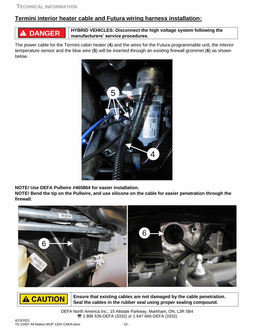
Termini interior heater cable and Futura wiring harness installation:
HYBRID VEHICLES: Disconnect the high voltage system following the
manufacturers’ service procedures.
The power cable for the Termini cabin heater (4) and the wires for the Futura programmable unit, the interior
temperature sensor and the blue wire (5) will be inserted through an existing firewall grommet (6) as shown
below.
NOTE! Use DEFA Pullwire #460864 for easier installation.
NOTE! Bend the tip on the Pullwire, and use silicone on the cable for easier penetration through the
firewall.
Ensure that existing cables are not damaged by the cable penetration.
Seal the cables in the rubber seal using proper sealing compound.
! DANGER
5
4
6
6
TECHNICAL INFORMATION
DEFA North America Inc., 15 Allstate Parkway, Markham, ON, L3R 5B4 1 888 539-DEFA (3332) or 1 647 660-DEFA (3332)
4/13/2021 TD 21007 All Makes WUP 120V CAEN.docx - 11 -
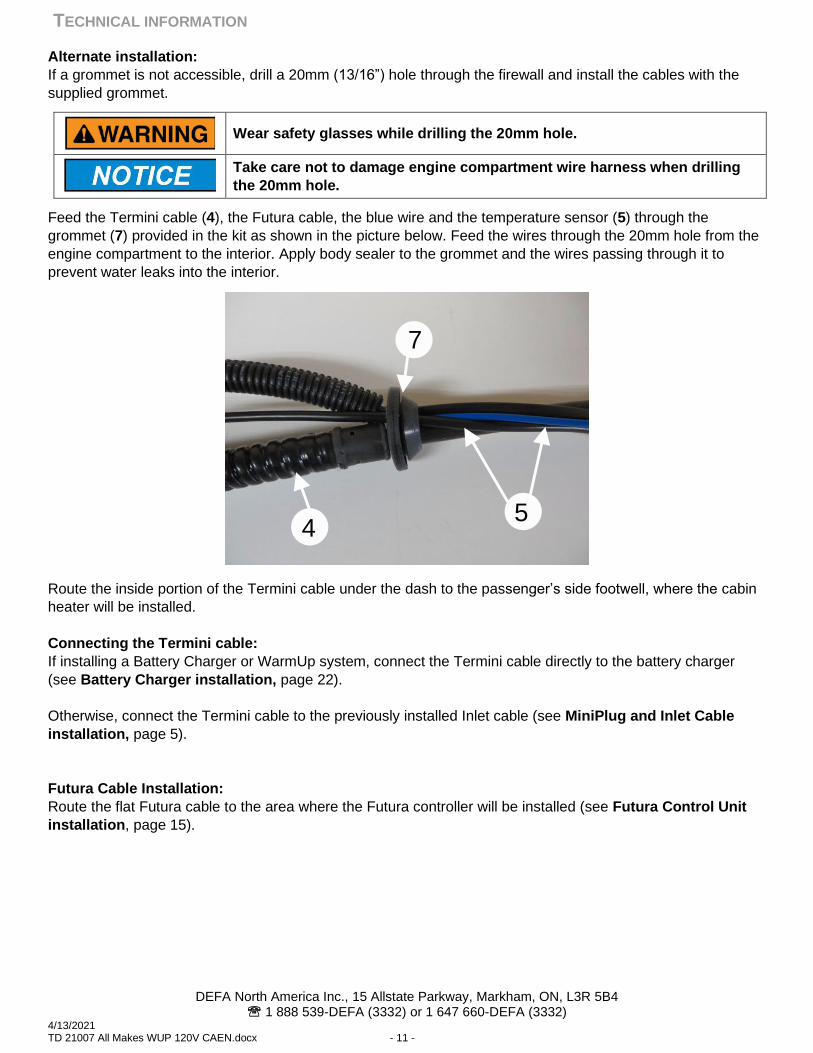
Alternate installation:
If a grommet is not accessible, drill a 20mm (13/16”) hole through the firewall and install the cables with the
supplied grommet.
Wear safety glasses while drilling the 20mm hole.
Take care not to damage engine compartment wire harness when drilling
the 20mm hole.
Feed the Termini cable (4), the Futura cable, the blue wire and the temperature sensor (5) through the
grommet (7) provided in the kit as shown in the picture below. Feed the wires through the 20mm hole from the
engine compartment to the interior. Apply body sealer to the grommet and the wires passing through it to
prevent water leaks into the interior.
Route the inside portion of the Termini cable under the dash to the passenger’s side footwell, where the cabin
heater will be installed.
Connecting the Termini cable:
If installing a Battery Charger or WarmUp system, connect the Termini cable directly to the battery charger
(see Battery Charger installation, page 22).
Otherwise, connect the Termini cable to the previously installed Inlet cable (see MiniPlug and Inlet Cable
installation, page 5).
Futura Cable Installation:
Route the flat Futura cable to the area where the Futura controller will be installed (see Futura Control Unit
installation, page 15).
7
54
TECHNICAL INFORMATION
DEFA North America Inc., 15 Allstate Parkway, Markham, ON, L3R 5B4 1 888 539-DEFA (3332) or 1 647 660-DEFA (3332)
4/13/2021 TD 21007 All Makes WUP 120V CAEN.docx - 12 -
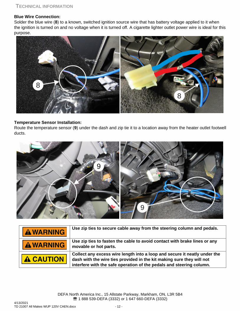
Blue Wire Connection:
Solder the blue wire (8) to a known, switched ignition source wire that has battery voltage applied to it when
the ignition is turned on and no voltage when it is turned off. A cigarette lighter outlet power wire is ideal for this
purpose.
Temperature Sensor Installation:
Route the temperature sensor (9) under the dash and zip tie it to a location away from the heater outlet footwell
ducts.
Use zip ties to secure cable away from the steering column and pedals.
Use zip ties to fasten the cable to avoid contact with brake lines or any
movable or hot parts.
Collect any excess wire length into a loop and secure it neatly under the
dash with the wire ties provided in the kit making sure they will not
interfere with the safe operation of the pedals and steering column.
16168
16168
9
9
TECHNICAL INFORMATION
DEFA North America Inc., 15 Allstate Parkway, Markham, ON, L3R 5B4 1 888 539-DEFA (3332) or 1 647 660-DEFA (3332)
4/13/2021 TD 21007 All Makes WUP 120V CAEN.docx - 13 -
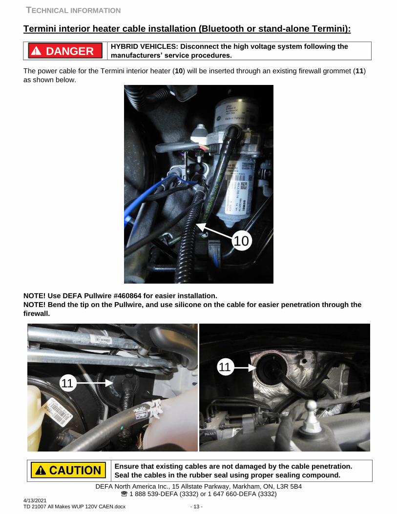
Termini interior heater cable installation (Bluetooth or stand-alone Termini):
HYBRID VEHICLES: Disconnect the high voltage system following the
manufacturers’ service procedures.
The power cable for the Termini interior heater (10) will be inserted through an existing firewall grommet (11)
as shown below.
NOTE! Use DEFA Pullwire #460864 for easier installation.
NOTE! Bend the tip on the Pullwire, and use silicone on the cable for easier penetration through the
firewall.
Ensure that existing cables are not damaged by the cable penetration.
Seal the cables in the rubber seal using proper sealing compound.
! DANGER
10
11
11
TECHNICAL INFORMATION
DEFA North America Inc., 15 Allstate Parkway, Markham, ON, L3R 5B4 1 888 539-DEFA (3332) or 1 647 660-DEFA (3332)
4/13/2021 TD 21007 All Makes WUP 120V CAEN.docx - 14 -
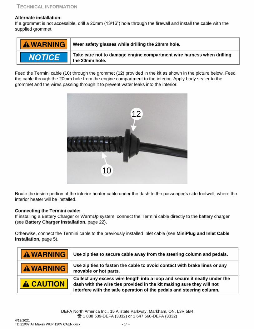
Alternate installation:
If a grommet is not accessible, drill a 20mm (13/16”) hole through the firewall and install the cable with the
supplied grommet.
Wear safety glasses while drilling the 20mm hole.
Take care not to damage engine compartment wire harness when drilling
the 20mm hole.
Feed the Termini cable (10) through the grommet (12) provided in the kit as shown in the picture below. Feed
the cable through the 20mm hole from the engine compartment to the interior. Apply body sealer to the
grommet and the wires passing through it to prevent water leaks into the interior.
Route the inside portion of the interior heater cable under the dash to the passenger’s side footwell, where the
interior heater will be installed.
Connecting the Termini cable:
If installing a Battery Charger or WarmUp system, connect the Termini cable directly to the battery charger
(see Battery Charger installation, page 22).
Otherwise, connect the Termini cable to the previously installed Inlet cable (see MiniPlug and Inlet Cable
installation, page 5).
Use zip ties to secure cable away from the steering column and pedals.
Use zip ties to fasten the cable to avoid contact with brake lines or any
movable or hot parts.
Collect any excess wire length into a loop and secure it neatly under the
dash with the wire ties provided in the kit making sure they will not
interfere with the safe operation of the pedals and steering column.
12
10
TECHNICAL INFORMATION
DEFA North America Inc., 15 Allstate Parkway, Markham, ON, L3R 5B4 1 888 539-DEFA (3332) or 1 647 660-DEFA (3332)
4/13/2021 TD 21007 All Makes WUP 120V CAEN.docx - 15 -
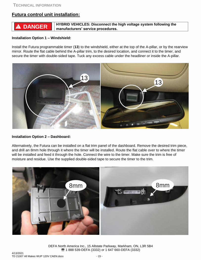
Futura control unit installation:
HYBRID VEHICLES: Disconnect the high voltage system following the
manufacturers’ service procedures.
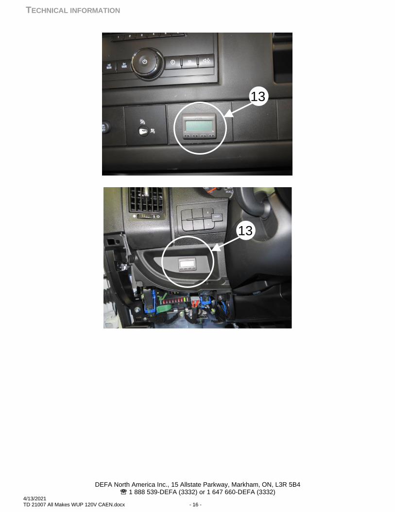
Installation Option 1 – Windshield:
Install the Futura programmable timer (13) to the windshield, either at the top of the A-pillar, or by the rearview
mirror. Route the flat cable behind the A-pillar trim, to the desired location, and connect it to the timer, and
secure the timer with double-sided tape. Tuck any excess cable under the headliner or inside the A-pillar.
Installation Option 2 – Dashboard:
Alternatively, the Futura can be installed on a flat trim panel of the dashboard. Remove the desired trim piece,
and drill an 8mm hole through it where the timer will be installed. Route the flat cable over to where the timer
will be installed and feed it through the hole. Connect the wire to the timer. Make sure the trim is free of
moisture and residue. Use the supplied double-sided tape to secure the timer to the trim.
! DANGER
1313
8mm 8mm
TECHNICAL INFORMATION
DEFA North America Inc., 15 Allstate Parkway, Markham, ON, L3R 5B4 1 888 539-DEFA (3332) or 1 647 660-DEFA (3332)
4/13/2021 TD 21007 All Makes WUP 120V CAEN.docx - 16 -
13
13
TECHNICAL INFORMATION
DEFA North America Inc., 15 Allstate Parkway, Markham, ON, L3R 5B4 1 888 539-DEFA (3332) or 1 647 660-DEFA (3332)
4/13/2021 TD 21007 All Makes WUP 120V CAEN.docx - 17 -
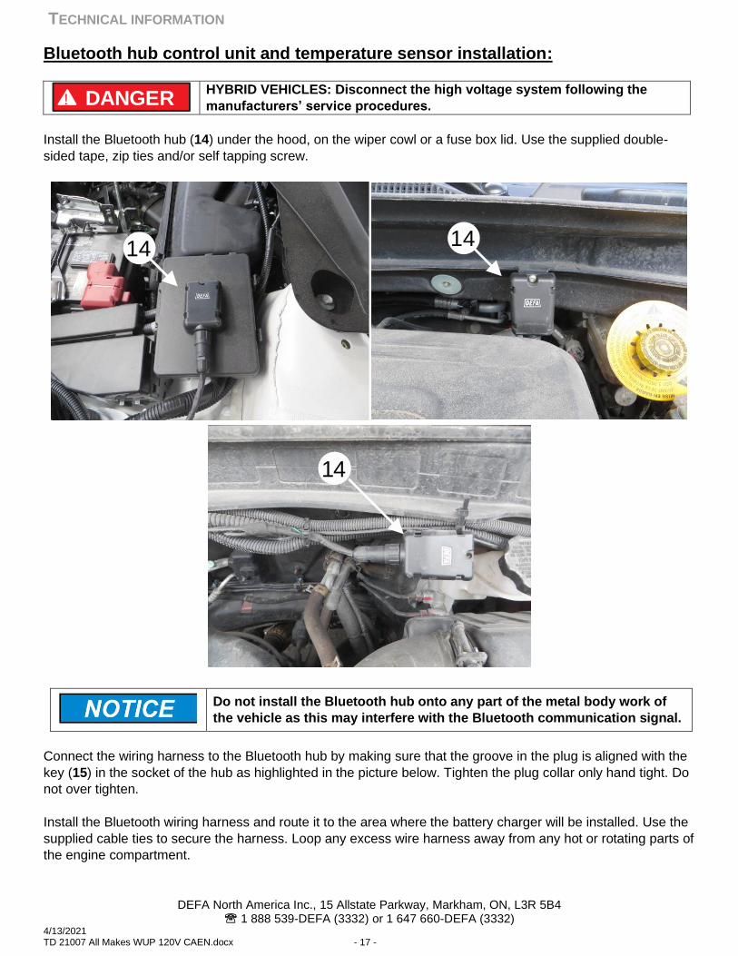
Bluetooth hub control unit and temperature sensor installation:
HYBRID VEHICLES: Disconnect the high voltage system following the
manufacturers’ service procedures.
Install the Bluetooth hub (14) under the hood, on the wiper cowl or a fuse box lid. Use the supplied double-
sided tape, zip ties and/or self tapping screw.
Do not install the Bluetooth hub onto any part of the metal body work of
the vehicle as this may interfere with the Bluetooth communication signal.
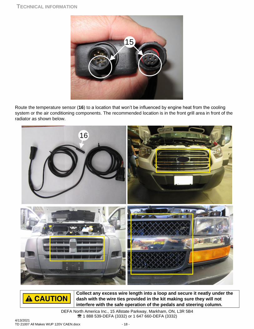
Connect the wiring harness to the Bluetooth hub by making sure that the groove in the plug is aligned with the
key (15) in the socket of the hub as highlighted in the picture below. Tighten the plug collar only hand tight. Do
not over tighten.
Install the Bluetooth wiring harness and route it to the area where the battery charger will be installed. Use the
supplied cable ties to secure the harness. Loop any excess wire harness away from any hot or rotating parts of
the engine compartment.
! DANGER
14 14
14
TECHNICAL INFORMATION
DEFA North America Inc., 15 Allstate Parkway, Markham, ON, L3R 5B4 1 888 539-DEFA (3332) or 1 647 660-DEFA (3332)
4/13/2021 TD 21007 All Makes WUP 120V CAEN.docx - 18 -
Route the temperature sensor (16) to a location that won’t be influenced by engine heat from the cooling
system or the air conditioning components. The recommended location is in the front grill area in front of the
radiator as shown below.
Collect any excess wire length into a loop and secure it neatly under the
dash with the wire ties provided in the kit making sure they will not
interfere with the safe operation of the pedals and steering column.
15
16
TECHNICAL INFORMATION
DEFA North America Inc., 15 Allstate Parkway, Markham, ON, L3R 5B4 1 888 539-DEFA (3332) or 1 647 660-DEFA (3332)
4/13/2021 TD 21007 All Makes WUP 120V CAEN.docx - 19 -
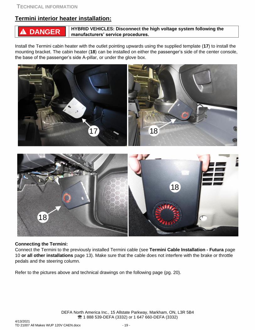
Termini interior heater installation:
HYBRID VEHICLES: Disconnect the high voltage system following the
manufacturers’ service procedures.
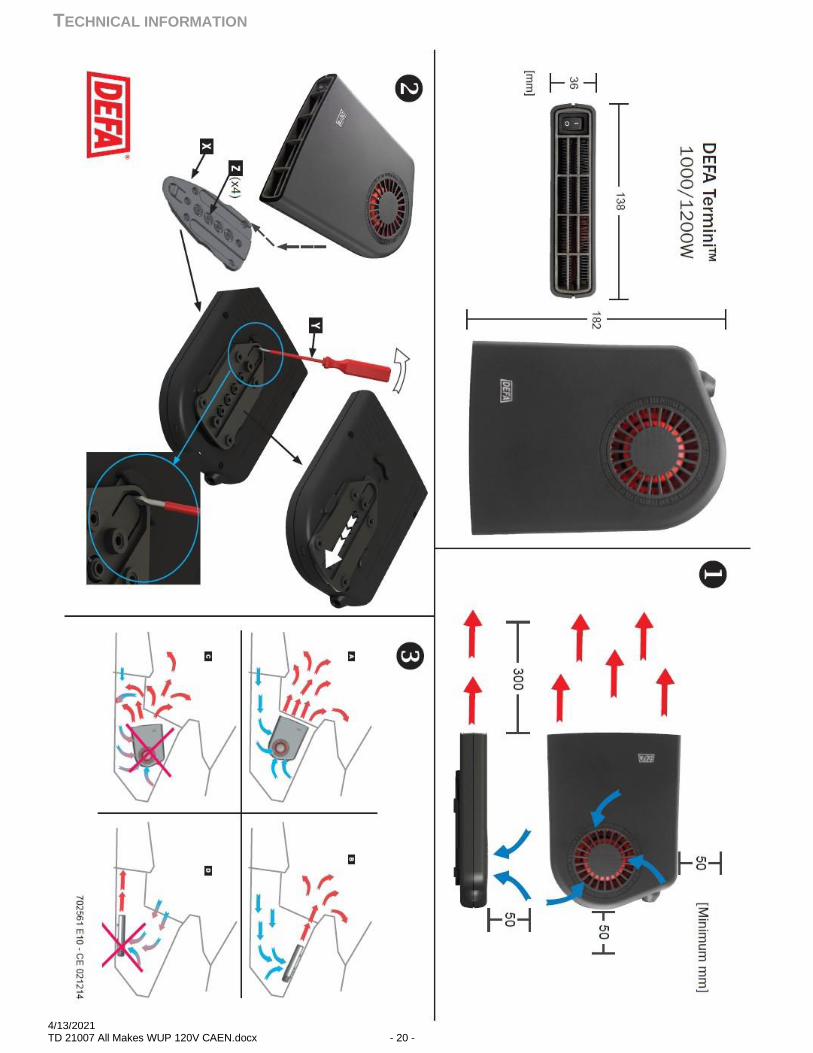
Install the Termini cabin heater with the outlet pointing upwards using the supplied template (17) to install the
mounting bracket. The cabin heater (18) can be installed on either the passenger’s side of the center console,
the base of the passenger’s side A-pillar, or under the glove box.
Connecting the Termini:
Connect the Termini to the previously installed Termini cable (see Termini Cable Installation - Futura page
10 or all other installations page 13). Make sure that the cable does not interfere with the brake or throttle
pedals and the steering column.
Refer to the pictures above and technical drawings on the following page (pg. 20).
! DANGER
17 18
18
18
TECHNICAL INFORMATION
DEFA North America Inc., 15 Allstate Parkway, Markham, ON, L3R 5B4 1 888 539-DEFA (3332) or 1 647 660-DEFA (3332)
4/13/2021 TD 21007 All Makes WUP 120V CAEN.docx - 20 -
TECHNICAL INFORMATION
DEFA North America Inc., 15 Allstate Parkway, Markham, ON, L3R 5B4 1 888 539-DEFA (3332) or 1 647 660-DEFA (3332)
4/13/2021 TD 21007 All Makes WUP 120V CAEN.docx - 21 -
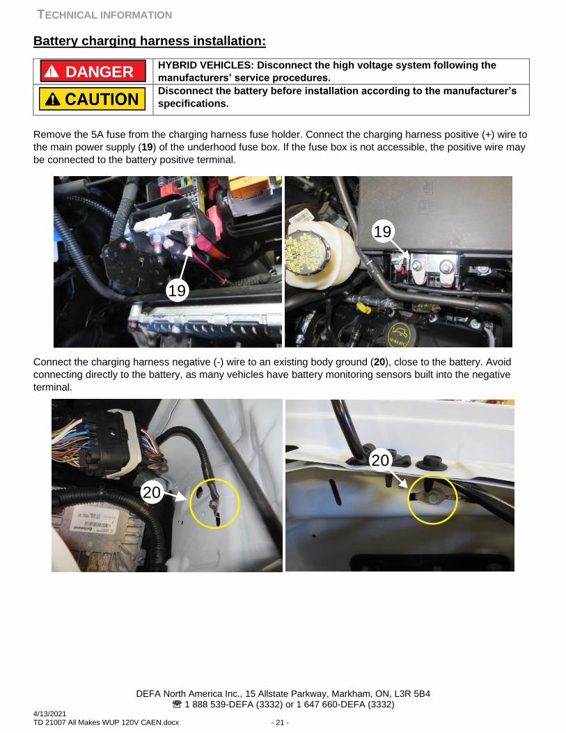
Battery charging harness installation:
HYBRID VEHICLES: Disconnect the high voltage system following the
manufacturers’ service procedures.
Disconnect the battery before installation according to the manufacturer’s
specifications.
Remove the 5A fuse from the charging harness fuse holder. Connect the charging harness positive (+) wire to
the main power supply (19) of the underhood fuse box. If the fuse box is not accessible, the positive wire may
be connected to the battery positive terminal.
Connect the charging harness negative (-) wire to an existing body ground (20), close to the battery. Avoid
connecting directly to the battery, as many vehicles have battery monitoring sensors built into the negative
terminal.
! DANGER
19
19
20
1020
TECHNICAL INFORMATION
DEFA North America Inc., 15 Allstate Parkway, Markham, ON, L3R 5B4 1 888 539-DEFA (3332) or 1 647 660-DEFA (3332)
4/13/2021 TD 21007 All Makes WUP 120V CAEN.docx - 22 -
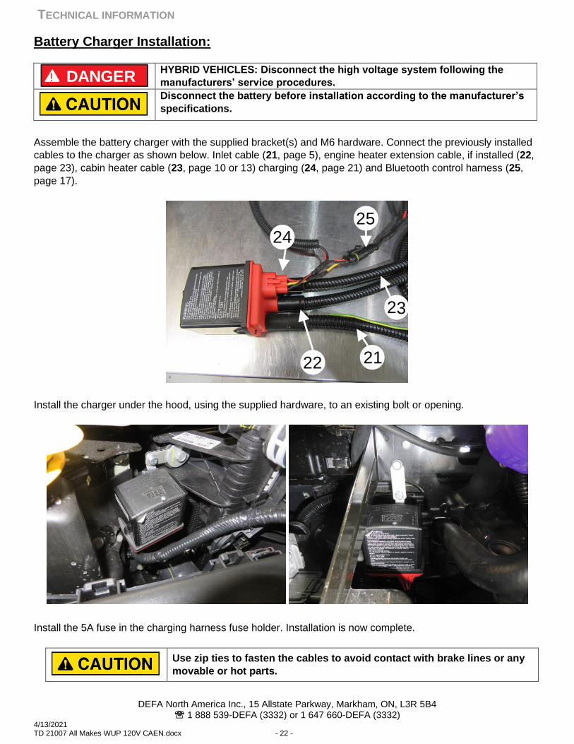
Battery Charger Installation:
HYBRID VEHICLES: Disconnect the high voltage system following the
manufacturers’ service procedures.
Disconnect the battery before installation according to the manufacturer’s
specifications.
Assemble the battery charger with the supplied bracket(s) and M6 hardware. Connect the previously installed
cables to the charger as shown below. Inlet cable (21, page 5), engine heater extension cable, if installed (22,
page 23), cabin heater cable (23, page 10 or 13) charging (24, page 21) and Bluetooth control harness (25,
page 17).
Install the charger under the hood, using the supplied hardware, to an existing bolt or opening.
Install the 5A fuse in the charging harness fuse holder. Installation is now complete.
Use zip ties to fasten the cables to avoid contact with brake lines or any
movable or hot parts.
! DANGER
22 21
23
2425
TECHNICAL INFORMATION
DEFA North America Inc., 15 Allstate Parkway, Markham, ON, L3R 5B4 1 888 539-DEFA (3332) or 1 647 660-DEFA (3332)
4/13/2021 TD 21007 All Makes WUP 120V CAEN.docx - 23 -
Engine heater installation:
Refer to the documents supplied with the engine heater for vehicle-specific instructions. The WarmUp kit does
not include the necessary extension cable to allow the completion of the kit with a DEFA engine heater
(available in 0.5m increments, up to 3.0m, sold separately).
NOTE: When adding an engine heater to a WarmUp kit, make sure that the combined wattage does not
exceed the 120V circuit to which it will be connected. A typical 120V circuit will have a 15-amp breaker, which
limits total output to 1800W.
Connecting the engine block heater:
If installing a Battery Charger or WarmUp system, use an extension cable (available separately) to connect the
engine heater to the battery charger (see Battery Charger installation, page 22). Loop and secure the excess
cable.
Otherwise, route the Inlet Cable directly to the engine heater (see MiniPlug and Inlet Cable installation, page
5).
DEFA WarmUp System:
KEY checks for good installation and functionality
BEFORE YOU START THE INSTALLATION
•Read all instructions before proceeding with the installation as procedures may overlap.
•Before installation, disconnect the battery as directed by the manufacturer.
DURING THE INSTALLATION
•Make sure to remove the drain tab from the MiniPlug before installation in the bumper.
•Ensure there is sufficient space between components to avoid chaffing or contact with
moving parts.
•Ensure the ground wire on the DEFA inlet cable is attached to a good clean chassis ground that is
void of paint to ensure a good ground connection.
TEST THE SYSTEM
•Do not turn the ignition on while checking the operation of the DEFA Preheating system.
•Connect the system using the complimentary power cable within the charger kit.
•The light on the charger will only come on when the battery is at a low state of charge
(Below 13.7V) and will not illuminate during the floating/maintaining states.
To test the charger, place a load on the battery such as an open door or headlights on.
MAINTENANCE
• It is highly recommended to regularly clean the MiniPlug housing during vehicle maintenance or more
frequently depending upon weather and road conditions.
Spray the inside of the MiniPlug housing with a suitable aerosol cleaner such as Electronic Parts
Cleaner. This will help to flush out any remaining moisture or debris accumulation from regular use.
R