table of contents operating and maintenance instructions … · 2017-05-16 · operating and...
TRANSCRIPT

TABLE OF CONTENTS
TOC
TABLE OF CONTENTS
TOC
Operating and maintenance instructions
for the drum dryer model GDZ
Keep for future
reference.
MA_H_GDZ_V01.docx
04/12/2014
2
INDEX
1 Key of indications. ................................................................................................. 7
1.1 Document release ............................................................................................... 7
2 Identification ........................................................................................................ 8
2.1 Appliance brand and designation of the type ........................................................... 8
2.2 Version of the appliance ....................................................................................... 8
2.3 Name and address of the manufacturer, supplier, and distributor ............................... 8
2.4 Pick up and delivery of the appliance by the carrier. ................................................. 9
2.5 Declaration of conformity ................................................................................... 10
3 Product specification ............................................................................................ 10
3.1 Intended use. ................................................................................................... 11
3.2 Improper use but reasonably predictable. ............................................................. 12
3.3 Dimensions and weight (for transport) ................................................................. 12
3.4 Data regarding power supply, gas, water, and other consumables. .......................... 13
3.5 Energy consumption .......................................................................................... 13
3.6 Emissions of noise, waste, etc. ........................................................................... 14
3.7 IP code ............................................................................................................ 14
3.8 Environmental conditions, operating and storage limits (transport) .......................... 14
3.9 Information relative to safety ............................................................................. 15
3.9.1 Fundamental rules. ...................................................................................... 15
3.9.2 Information regarding residual risks ............................................................... 17
4 Definitions .......................................................................................................... 19
4.1 Symbols (labels) applied to the appliance ............................................................. 20
5 Preparation of the product for use .......................................................................... 23
5.1 Transport and storage ....................................................................................... 23
5.2 Safety precautions to be taken before use ............................................................ 23
5.3 Unpacking ....................................................................................................... 24
5.4 Safe disposal of packaging materials ................................................................... 25
5.5 Operations to be carried out before installation ..................................................... 26
5.5.1 Serial number plate for models with electric or steam heating. ........................... 26
5.5.2 Serial number plate for models with gas heating. ............................................. 27
5.6 Installation and assembly .................................................................................. 28
5.6.1 Open the panels on all appliance models ......................................................... 28
5.6.2 Construction work ....................................................................................... 28
5.6.3 Feet adjustment .......................................................................................... 28
5.7 Connection of the fumes discharge for models with electric and steam heating .......... 29
5.7.1 Increase coefficients for installation of curves and fittings ................................. 29
5.7.2 Fresh air .................................................................................................... 30
5.8 Steam supply connection (only where necessary) .................................................. 31
5.8.1 Connection diagram of the appliance with steam heating ................................... 32

3
5.8.2 Liquid expansion thermostatic trap ................................................................ 33
5.8.3 Thermostatic trap ........................................................................................ 33
5.8.4 Steam trap with float ................................................................................... 33
5.8.5 Inverted bucket steam trap........................................................................... 33
5.8.6 Thermodynamic steam trap .......................................................................... 33
5.9 Steam battery filter ........................................................................................... 34
5.10 Gas connection: installation of appliances with gas heating ................................... 34
5.10.1 Type of appliance with gas heating ............................................................... 34
5.10.2 Gas tables ................................................................................................ 36
5.10.3 Flue evacuation gas heating version ............................................................. 38
5.10.4 Connection of the gas distribution network to the appliance ............................. 39
5.11 Specific checks on the calibration of the dryer for other types of gas ...................... 39
5.11.1 Flame quality ............................................................................................ 39
5.11.2 What to do if you smell gas ......................................................................... 40
5.11.3 Instructions on how to modify the appliance calibration for other types of gas. ... 40
5.11.4 Special cases: FR/BE diaphragm installation and 1st family gases ..................... 41
5.12 Check the rotation direction of the extractor. ...................................................... 41
5.13 Setting and adjusting the gas valve. .................................................................. 42
5.13.1 Description of the gas valve. ....................................................................... 42
5.13.2 How to adjust the pressure. ........................................................................ 43
5.13.3 Gas pressure adjustment to the valve. .......................................................... 43
5.13.4 Bleeding operations of the gas supply network. .............................................. 43
5.13.5 Gas adjustment procedure. ......................................................................... 43
5.13.6 Precautions to be taken for all models .......................................................... 44
5.13.7 Replacement of the nozzle .......................................................................... 45
5.14 Electric connections ......................................................................................... 45
5.14.1 Special features of the electrical connection ................................................... 47
5.14.1.1 Power supply connection 380-400-415 3~ + N ............................................ 48
5.14.1.2 Power supply connection 380-400-415-440 3~ or 220-230-240 3~. ............... 48
5.14.1.3 SINGLE-PHASE 220-230-240 power supply connection. ................................ 49
5.15 Ergonomic installation of the appliances ............................................................. 49
5.16 Testing .......................................................................................................... 49
5.17 Storage and protection during intervals between normal use periods ...................... 50
5.18 Re-packaging to prevent damage during transport ............................................... 50
5.19 Information assignment (users, operators, maintenance experts) .......................... 50
5.19.1 Location of the instructions ......................................................................... 51
5.20 Warranty ....................................................................................................... 51
6 Operating instructions .......................................................................................... 51
6.1 Chemical hazard ............................................................................................... 52
6.2 Operating in safe conditions ............................................................................... 52
6.3 Routine operation ............................................................................................. 53

4
6.3.1 Description of the appliance and of the control panel ........................................ 53
6.3.2 Display description ...................................................................................... 54
6.3.3 Door opening .............................................................................................. 54
6.4 Useful tips on the use of the appliance ................................................................. 54
6.4.1 Symbols (tags) applied on the fabrics ............................................................. 55
6.5 Preparing for a drying program ........................................................................... 57
6.6 Function of the control panel keys ....................................................................... 57
6.7 Automatic execution of a program ....................................................................... 58
6.8 Starting diagram of a drying cycle ....................................................................... 58
6.8.1 Cycle sequence with 3 drying modules (basic version) ...................................... 59
6.8.2 Sequence of cycle with 3 drying modules and temperature probe T2 option ......... 60
6.8.3 Sequence of cycle with 3 drying modules with relative humidity probe option. ...... 61
6.8.4 Description of standard programs supplied with the appliance ............................ 62
6.8.5 Description of modified programs .................................................................. 62
6.9 Production to the program ................................................................................. 63
6.9.1 Programming the cycles. .............................................................................. 63
6.9.1.1 Cycle programming limit. ........................................................................... 66
6.9.2 Technical user level (T) enabling procedure ..................................................... 66
6.9.3 Tips for drying delicate garments ................................................................... 66
6.9.4 Machine parameters menu ............................................................................ 67
6.9.4.1 Table 1: parameters –values – enabled users ............................................... 67
6.9.4.2 Table 2: meaning of parameter menu items ................................................. 68
6.9.4.3 Navigation in parameters menu .................................................................. 69
6.9.5 Checking status of digital inputs and DIP SWITCHES ........................................ 70
6.10 Loading "default parameters" (reset operation) ................................................... 72
6.11 Restoring default parameters of inverter and modifying speed settings ................... 72
6.12 Power cut during operation ............................................................................... 73
6.13 Deletion of an alarm ........................................................................................ 73
7 Safety functions and devices ................................................................................. 74
8 cleaning and maintenance .................................................................................... 75
8.1 In general ........................................................................................................ 75
8.2 Cleaning. ......................................................................................................... 75
8.2.1 Daily cleaning ............................................................................................. 75
8.2.2 Weekly cleaning. ......................................................................................... 76
8.2.3 Monthly cleaning. ........................................................................................ 76
8.2.4 Daily, weekly and monthly maintenance and cleaning register ........................... 77
8.2.5 Releasing laundry and drum maintenance ....................................................... 77
8.3 Maintenance: types and warnings ...................................................................... 77
8.3.1 Routine maintenance: operation of safety systems and cleaning. Cleaning frequency. .......................................................................................................... 78
8.3.2 Routine maintenance: lubrication of bearings. Every three months. .................... 79
5
8.3.3 Routine maintenance: check the state and adjustment of the belts. Every 6 months. ........................................................................................................................ 80
8.3.4 Routine maintenance: cleaning extractor fan and filter compartment. Monthly. .... 81
8.3.5 Extraordinary maintenance: annual check valid for all versions. ......................... 83
8.3.6 Extraordinary maintenance: additional annual check for versions with gas heating.
........................................................................................................................ 83
8.3.7 Required maintenance: replace inverter and restore parameters. ....................... 84
8.3.8 Maintenance and cleaning form to be filled in by qualified personnel ................... 86
9 Troubleshooting .................................................................................................. 87
9.1 Description of alarms, possible causes and solutions. ............................................. 87
10 optional functions and accessories available. .......................................................... 92
10.1 Temperature and relative humidity probe T2. ...................................................... 92
10.2 Two-stage electric heating. ............................................................................... 92
10.3 Two-stage gas heating. .................................................................................... 92
10.4 50%-100% electric heating selector switch ......................................................... 93
10.5 Self-service configuration ................................................................................. 93
10.5.1 External emergency stop installation in self-service configuration ..................... 93
10.5.2 Types of payment systems available ............................................................. 93
10.5.2.1 Centralised cash register connection. ......................................................... 93
10.5.3 Self-service mode. ..................................................................................... 96
10.5.3.1 Payment with impulses system ................................................................. 96
10.5.3.2 Payment with parallel system ................................................................... 96
10.5.3.3 Payment by key reader or prepaid cards .................................................... 96
10.5.3.4 Credit management. ................................................................................ 97
10.5.3.5 Useful information. .................................................................................. 97
10.5.3.6 Display .................................................................................................. 98
10.6 Energy saving ................................................................................................. 98
10.7 Finishing function ............................................................................................ 98
10.8 Simplified check .............................................................................................. 99
10.8.1 General information ................................................................................... 99
10.8.2 Limits compared to the standard version ....................................................... 99
10.8.3 Comparison of the user interface. ................................................................ 99
10.8.4 Settings. ................................................................................................ 100
10.8.5 Programming .......................................................................................... 100
10.8.6 Preset cycles ........................................................................................... 100
11 Assistance service addresses, spare parts and consumables order........................... 101
12 List of spare parts and consumables. .................................................................. 102
12.1 Recommended spare part list .......................................................................... 102
12.2 Diagrams. .................................................................................................... 102
12.3 Decommissioning .......................................................................................... 103
12.3.1 Waste disposal ........................................................................................ 103
12.3.2 Information for users ............................................................................... 103

6
Translation of Original instructions.
(note for translation: replace “original instructions” with “translation of original instructions)
For any claims or observations, the reference text is the original one in the manufacturer's
language i.e. Italian.

7
1 KEY OF INDICATIONS.
Attention!
It shows a procedure or functioning condition, assembly or testing that, if not complied with, may cause death or injury to persons
and animals, and damage to objects.
Attention! It shows a procedure or functioning condition, assembly or testing
that, if not complied with, may cause damage to or destruction of equipment or components that are part of the machine.
It shows a procedure or functioning condition that, in addition to
being binding, can help you improve the manufacturing, building or assembly of the components stated in the present instructions.
This manual provides appliance transport, installation, operation and maintenance instructions
for models: GDZ11
GDZ14
GDZ18
GDZ24
With electric, gas and steam heating.
1.1 Document release
Ver. Document
name
Network archiving address Author Date Appro
ved
Date
00 MA_H_GDZ_V00
S:\110_PROGETTI\P-21_GD11-14-18-
24\P21-54-Documentazione-Manuali-
Schemi\Manuale GD
V00\MA_H_GDZ_V00.docx\
A. Bogo 17/01/14 U. Bulf
01 MA_H_GDZ_V
01
S:\110_PROGETTI\P-21_GD11-14-18-
24\P21-54-Documentazione-Manuali-
Schemi\Manuale GD
V01\MA_H_GDZ_V01.docx\
Porta G. 04/12/14
This manual has been drawn-up in compliance with the following Standards:
EN 60204-1 EN 60335-1
EN 60335-2
ISO 12100-2 ISO 10472-1
ISO 10472-4
ISO 9398-2:2003
8
2 IDENTIFICATION
Make sure that the delivered appliance corresponds with the model stated on the transport
document or invoice. The model is stated on the label positioned on the packaging, as well as on the rear closing panel of the appliance.
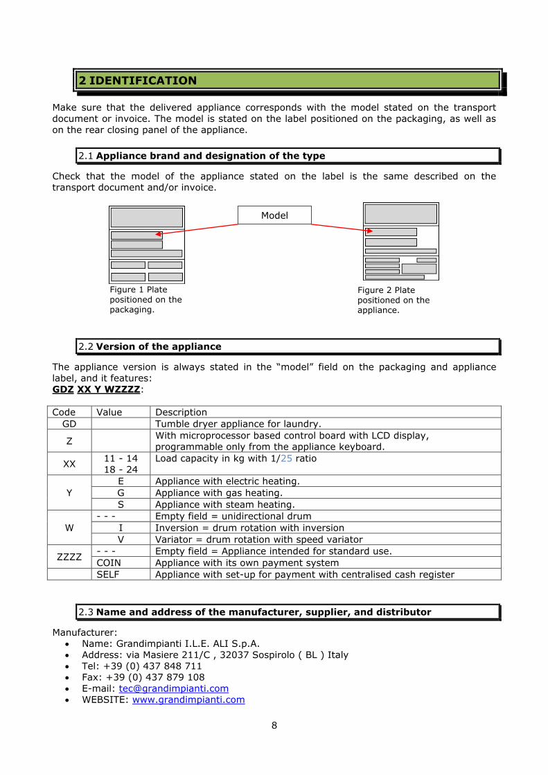
2.1 Appliance brand and designation of the type
Check that the model of the appliance stated on the label is the same described on the transport document and/or invoice.
2.2 Version of the appliance
The appliance version is always stated in the “model” field on the packaging and appliance
label, and it features: GDZ XX Y WZZZZ:
Code Value Description
GD Tumble dryer appliance for laundry.
Z With microprocessor based control board with LCD display, programmable only from the appliance keyboard.
XX 11 - 14
18 - 24
Load capacity in kg with 1/25 ratio
Y
E Appliance with electric heating.
G Appliance with gas heating.
S Appliance with steam heating.
W
- - - Empty field = unidirectional drum
I Inversion = drum rotation with inversion
V Variator = drum rotation with speed variator
ZZZZ - - - Empty field = Appliance intended for standard use.
COIN Appliance with its own payment system
SELF Appliance with set-up for payment with centralised cash register
2.3 Name and address of the manufacturer, supplier, and distributor
Manufacturer: Name: Grandimpianti I.L.E. ALI S.p.A.
Address: via Masiere 211/C , 32037 Sospirolo ( BL ) Italy
Tel: +39 (0) 437 848 711 Fax: +39 (0) 437 879 108
E-mail: [email protected] WEBSITE: www.grandimpianti.com
Figure 2 Plate positioned on the appliance.
Figure 1 Plate positioned on the packaging.
Model

9
Supplier (importer):....
IMPORTER STAMP....
Distributor:...................
DISTRIBUTOR STAMP
2.4 Pick up and delivery of the appliance by the carrier.
Attention!
Before accepting the appliance from the carrier, check the conditions of the packaging. If evident external damage is found,
the appliance may also have undergone consequences (this task is facilitated in appliances with wooden cage). In this case, unpack
the appliance in the presence of the carrier and sign the relative transport document applying the note ''subject to confirmation''.
Any damage due to transport or incorrect storage cannot be
blamed on the appliance manufacturer.
10
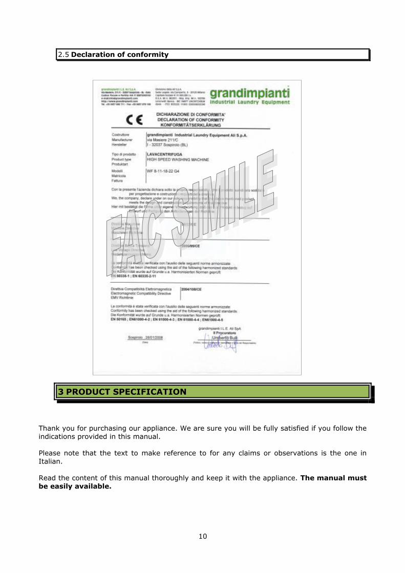
2.5 Declaration of conformity
3 PRODUCT SPECIFICATION
Thank you for purchasing our appliance. We are sure you will be fully satisfied if you follow the indications provided in this manual.
Please note that the text to make reference to for any claims or observations is the one in
Italian.
Read the content of this manual thoroughly and keep it with the appliance. The manual must
be easily available.
11
In the event of interventions on the appliance, the manufacturer recommends using original spare parts, which must be ordered after consultation of the technical attachment.
The descriptions and illustrations contained in this manual are not binding; therefore, the company reserves the right to update the publication, any time and without prior notice,
and/or make any modifications to parts, components and accessories, if this is deemed necessary for improvement or to meet any construction or sales requirements.
3.1 Intended use.
The appliance has been designed: to dry fabric with load and volume limits in accordance with model specifications.
to be used in industrial, commercial and residential environments. to be used in self-service laundries
The appliance has NOT been designed:
to treat fabrics soaked with flammable substances, solvents, acids, grease.
to treat materials different from fabric. to protect from biological risks.
The appliance has been designed and manufactured to operate in safe conditions if:
it is used within the limits described in this manual; procedures described in this manual are adhered to;
routine maintenance is carried out at intervals and with the methods indicated in this manual;
extraordinary maintenance is carried out promptly in case of necessity;
safety devices are not removed and/or bypassed.
Attention! Any person using this appliance must read this user manual.
In case it is necessary to treat special fabrics, please contact in advance the after-sales assistance of the manufacturer.
Please follow the drying instructions indicated on fabric labels. The manufacturer declines any responsibility for damage to
fabrics caused by incorrect drying procedures.
Attention!
Any other use that is not explicitly indicated must be considered dangerous.
The manufacturer cannot be held liable for any damage deriving from use that is improper, incorrect or unreasonable or, however,
not stated in this manual. The appliance cannot be used by persons (including children) with
reduced physical, sensory, mental capacities or with little
experience or knowledge, unless they have been examined or trained regarding the use of the appliance by suitably trained staff
that is responsible for their safety. Children should be supervised to make sure they do not play with
the appliance

12
The recommendations and warnings contained in this manual cannot cover all possibilities; it is important to use common sense, attention and caution. These are features that the
manufacturer cannot add to the machine but must be a priority for the persons carrying out
installation, maintenance and/or using the machine.
3.2 Improper use but reasonably predictable.
Treatment of materials different from fabric. Use of the appliance in an environment subject to weather conditions (and exposure of
system to lightning) Use in an environment with high risk of fire and/or explosion
Use in environments subject to electromagnetic disturbances.
Attention!
Modifications of the electric, electronic or mechanical components
and to their relative positions can only be made after written authorisation of the manufacturer.
3.3 Dimensions and weight (for transport)
Follow recommendations below for transport and/or shipping:
only use the original or equivalent pallet. use the manual or electric forklift with sufficient lifting capacity and fork length (see
table and fig. 3). check that the appliance can overcome all obstacles e.g. stairs, doors etc.
Use the original packaging to ship the appliance
The product must be stored indoors and protected from the elements.
Appliance model Gross
weight (kg)
Width*
(mm)
Depth*
(mm)
Height*
(mm)
Minimum fork
length X (mm)
kg 11 215/225(**) 895 1120 1670 1100
kg 14 225/235(**) 895 1285 1670 1100
kg 18 292/302(**) 1070 1190 1900 1100
Kg 24 311/321(**) 1070 1405 1900 1300
(*) measurements of the packaged appliance. (**) without/with inversion.
Figure 1 Appliance
transport.

13
3.4 Data regarding power supply, gas, water, and other consumables.
The appliance is set-up with an electric power supply input and, according to the type of
heating, also a steam power supply input and condensate drain or GAS input. The inputs are displayed in figure 4 and the dimensions for the connections are stated in the table.
3.5 Energy consumption
Current absorption, hourly steam consumption and gas consumption for the different appliances.
Appliance
model 11-14 kg 18-24 kg
A, electric
power supply input.
PG 21 PG 29 ( PG16 gas
and steam heating )
B, steam input
connection. 1” 1”
C, condensate drain
connection.
¾” ¾”
D, gas
connection. ½”
Appliance model
Heating type kg 11 kg 14 kg 18 Kg 24
Electric Max power (kW) 12 16.5 23 32
GAS
GAS heat capacity (kW) 13-18 13-18 16-24 16-24
Max gas capacity G110 (m³/h) 4.7 4.7 4.7 (reduced
power)
4.7 (reduced
power)
Max gas capacity G20 (m³/h) 1.9 1.9 2.53 2.53
Max gas capacity G31 (m³/h) 0.75 0.75 1.00 1.00
Electric absorption (kW) 1.5 1.5 2 2
Steam
Dry saturated steam pressure (MPa) 0.40 – 0.60 0.40 – 0.60 0.40 – 0.60 0.40 – 0.60
Electric absorption (kW) 1.5 1.5 2 2
Steam consumption (Kg/h) 45 45 62 62
B
D
C
A
Figure 4 position of power supply, gas, and
steam inputs, and condensate output.
14
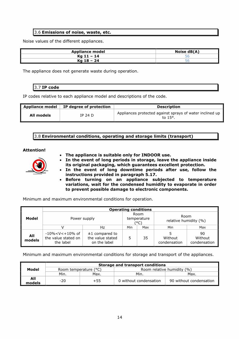
3.6 Emissions of noise, waste, etc.
Noise values of the different appliances.
Appliance model Noise dB(A)
Kg 11 – 14 56
Kg 18 – 24 56
The appliance does not generate waste during operation.
3.7 IP code
IP codes relative to each appliance model and descriptions of the code.
Appliance model IP degree of protection Description
All models IP 24 D Appliances protected against sprays of water inclined up
to 15°.
3.8 Environmental conditions, operating and storage limits (transport)
Attention!
The appliance is suitable only for INDOOR use. In the event of long periods in storage, leave the appliance inside
its original packaging, which guarantees excellent protection.
In the event of long downtime periods after use, follow the instructions provided in paragraph 5.17.
Before turning on an appliance subjected to temperature variations, wait for the condensed humidity to evaporate in order
to prevent possible damage to electronic components.
Minimum and maximum environmental conditions for operation.
Model
Operating conditions
Power supply Room
temperature
(°C)
Room relative humidity (%)
V Hz Min Max Min Max
All models
-10%<V<+10% of
the value stated on the label
±1 compared to
the value stated on the label
5 35
5
Without condensation
90
Without condensation
Minimum and maximum environmental conditions for storage and transport of the appliances.
Model
Storage and transport conditions
Room temperature (°C) Room relative humidity (%)
Min. Max. Min. Max.
All
models -20 +55 0 without condensation 90 without condensation

15
3.9 Information relative to safety
Attention! This paragraph states conditions and behaviour to comply with to
prevent dangerous conditions for persons, animals, objects or the
environment. Read what is stated thoroughly and keep this manual close to the
appliance for easy consultation!
In the event of failure and/or malfunction: disconnect the plug from the socket (if provided).
lock the interlocked switch with a padlock close the load cocks/gate valves (GAS, steam inlet and steam condensate discharge)
During use, cleaning and maintenance, pay attention not to access moving parts (motors,
fans) with tools, much less with your hands.
In the event of accidents, the manufacturer will not be liable for damage to the operator or
other persons occurring during use, cleaning and maintenance of the appliance.
3.9.1 Fundamental rules.
Using any electric or electronic appliance involves compliance with several fundamental rules:
Attention!
Do not touch the appliance with wet or damp hands or feet. Do not use the appliance barefoot.
Do not leave the appliance exposed to weather agents (rain,
salt, sea salt etc.). Do not smoke close to the appliance during use.
Do not remove or by-pass safety devices. Never use direct or indirect water jets on the appliance; pay
attention not to install it close to areas where this could happen.
The disconnector switch input contacts are always live even if the switch is in the off position!
The electric connection and especially the earth wire
connection must be made and checked by authorised personnel in compliance with the local Standards.
The appliance must have a permanent connection to the earth clamp and the equipotential clamp must be connected with
other appliances available in the same place.

16
Attention!
Given the appliance characteristics, to avoid any danger due to accidental rearm of the thermal interruption device, this appliance
must not be supplied by means of an external controller, such as a timer, or be connected to a circuit regularly connected to or
disconnected from power by service. The appliance must not be installed on a wooden floor even if it is
reinforced. Do not use the appliance if parts do not function or have been
removed. If the plastic membrane positioned on the appliance control keys
is damaged-broken do not use the appliance. Replace the
damaged membrane. Perform maintenance according to the schedule indicated in this
manual. If body parts should come into contact with liquid leaking from a
damaged display unit, wash using soap and water. Seek medical help in the event of accidental ingestion.
Do not treat items that have been in contact with flammable chemical materials. Hand-wash them first and dry them outdoors
to make these substances evaporate.
The steam intake piping and the condensate return piping can reach very high temperatures, as can all steam and condensate
control, filtering and drain devices even when cycle is not in progress.
Do not enter in the drum. If it is necessary to work inside the drum to release the laundry or carry out maintenance operations,
refer to the chapter on cleaning and maintenance. During the laundry loading and unloading phases, pay attention to
drum temperature. The drum temperature may be high especially
if the cycle is interrupted before carrying out the cooling phase normally envisaged.
Provide one or more fire extinguishers near to the appliance.
17
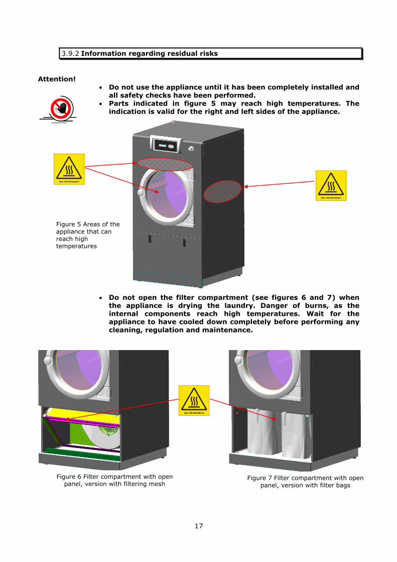
3.9.2 Information regarding residual risks
Attention!
Do not use the appliance until it has been completely installed and all safety checks have been performed.
Parts indicated in figure 5 may reach high temperatures. The indication is valid for the right and left sides of the appliance.
Do not open the filter compartment (see figures 6 and 7) when the appliance is drying the laundry. Danger of burns, as the
internal components reach high temperatures. Wait for the appliance to have cooled down completely before performing any
cleaning, regulation and maintenance.
Figure 5 Areas of the
appliance that can reach high temperatures
Figure 6 Filter compartment with open panel, version with filtering mesh
Figure 7 Filter compartment with open panel, version with filter bags

18
Attention! Do not put your hands or objects into the fume discharge shown
in figure 8. This opening is required for operation/installation of
the appliance and is located on the lower rear area.
Attention! Never put your hands or objects into the fitting made for
discharging fumes (see figure 8). It must be connected only to the fume evacuation flue.
Do not put your hands or objects into the appliance lower rear air
vent (see figure 8).
Attention!
Do not touch steam inlet and outlet pipes when hot. Burn injury
hazard. (See paragraph 5.8)
Figure 8 Opening in the presence of moving components

19
4 DEFINITIONS
To help you understand some of the more uncommon terms found in the manual, the
definitions and synonyms of some of the words used are provided below.
Appliance = product described in the manual (the tumble dryer in this case).
User = person who:
Is in charge of using the appliance. Has read and understood all pertinent parts of this manual.
Is able to perform routine maintenance and clean the appliance. Is informed in the terms indicated below.
Heating = drying phase of the cycle in which the appliance heats the air which hits the
laundry up to a value pre-established from the drying cycle selected.
Drying = main phase of the drying cycle in which the appliance maintains the temperature of
the air that hits the laundry as near as possible to the value pre-established from the selected drying cycle.
Cooling = final phase of the drying cycle in which the appliance indicates the temperature of
the air that hits the laundry at an acceptable value for the operator who will manage the washed laundry.
Anti-crease function = phase of the drying cycle that keeps the drum rotating if the drying
cycle has finished and the door has not yet been opened. It is used to prevent the formation of
difficult-to-iron creases. It stays on for a time predetermined in the program or until the door is opened.
Guard = part of an appliance used to provide protection by means of a physical barrier.
Damage = physical injury, damage to persons' health, deterioration of assets or of the environment.
Danger = potential source of damage.
Protection device = protection (different from a guard) which reduces risk (mechanical or electric devices).
Risk = combination of the probability of damage occurring and of its seriousness.
Informed person = person suitably informed or monitored by a trained person to allow them
to perceive risks and prevent danger potentially created by the appliance operation or maintenance.
Qualified technician = trained and experienced person able to perceive risks and prevent danger that can derive from interaction with the appliance.

20
4.1 Symbols (labels) applied to the appliance
Description Symbol Description Symbol
At the end of its useful
life, the product must
be collected separately
from other waste.
Conformity
marking on the
product in
compliance with
EC Standards.
Attention, electrical
hazard: disconnect the
appliance from the
mains before any
interventions.
Instructions for
resetting the
safety thermostat.
Greasing the bearings,
mandatory every 750
hours.
Attention, read
the instructions!
Appliance safety earth
connection.
Appliance earth
connection.
Attention, crushing
hazard: Only use
original spare parts.
Once repairs and
maintenance have been
completed, restore all
panels in their original
positions.
Attention,
electrical hazard:
disconnect the
appliance from the
mains before any
interventions.
Equipotential
connection.
Attention,
electrical hazard,
400Vac voltage
Burn injury hazard.
Burn injury
hazard.
Extraction motor
direction rotation.
Room installation
and ventilation
requisites.
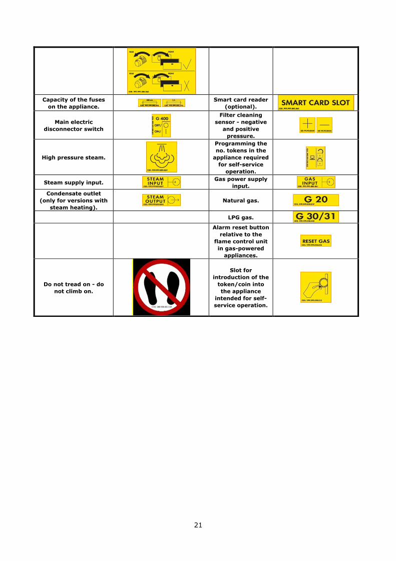
21
Capacity of the fuses
on the appliance. Smart card reader
(optional).
Main electric
disconnector switch
Filter cleaning
sensor - negative
and positive
pressure.
High pressure steam.
Programming the
no. tokens in the
appliance required
for self-service
operation.
Steam supply input.
Gas power supply
input.
Condensate outlet
(only for versions with
steam heating).
Natural gas.
LPG gas.
Alarm reset button
relative to the
flame control unit
in gas-powered
appliances.
Do not tread on - do
not climb on.
Slot for
introduction of the
token/coin into
the appliance
intended for self-
service operation.

22
23
5 PREPARATION OF THE PRODUCT FOR USE
It includes unpacking/packing, handling and transport operations performed between the
delivery of the appliance and the actual installation, the re-installation or the disposal thereof.
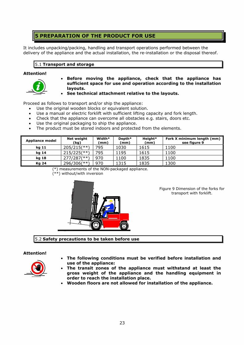
5.1 Transport and storage
Attention!
Before moving the appliance, check that the appliance has sufficient space for use and operation according to the installation
layouts. See technical attachment relative to the layouts.
Proceed as follows to transport and/or ship the appliance: Use the original wooden blocks or equivalent solution.
Use a manual or electric forklift with sufficient lifting capacity and fork length. Check that the appliance can overcome all obstacles e.g. stairs, doors etc.
Use the original packaging to ship the appliance. The product must be stored indoors and protected from the elements.
Appliance model Net weight
(kg)
Width*
(mm)
Depth*
(mm)
Height*
(mm)
Fork X minimum length (mm)
see figure 9
kg 11 205/215(**) 795 1030 1615 1100 kg 14 215/225(**) 795 1195 1615 1100 kg 18 277/287(**) 970 1100 1835 1100 Kg 24 296/306(**) 970 1315 1835 1300
(*) measurements of the NON-packaged appliance.
(**) without/with inversion
5.2 Safety precautions to be taken before use
Attention! The following conditions must be verified before installation and
use of the appliance: The transit zones of the appliance must withstand at least the
gross weight of the appliance and the handling equipment in order to reach the installation place.
Wooden floors are not allowed for installation of the appliance.
Figure 9 Dimension of the forks for transport with forklift.
24
Check that the electric absorption of the appliance is lower than that supplied by the electric company.
Check that the steam pressure available (for appliances running
with this type of heating) is within the accepted values. Check that the pressure and the type of GAS available in the
distribution network are those stated on the appliance serial plate.
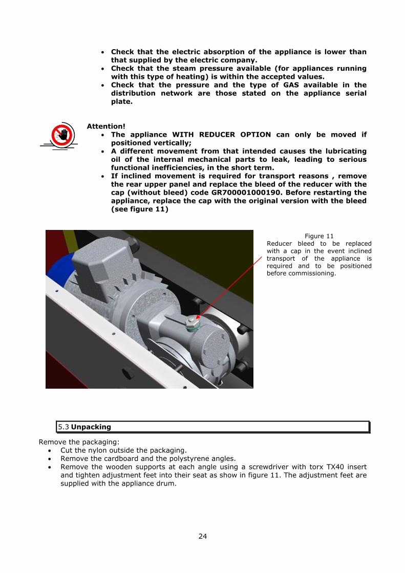
Attention! The appliance WITH REDUCER OPTION can only be moved if
positioned vertically; A different movement from that intended causes the lubricating
oil of the internal mechanical parts to leak, leading to serious
functional inefficiencies, in the short term. If inclined movement is required for transport reasons , remove
the rear upper panel and replace the bleed of the reducer with the cap (without bleed) code GR700001000190. Before restarting the
appliance, replace the cap with the original version with the bleed (see figure 11)
5.3 Unpacking
Remove the packaging:
Cut the nylon outside the packaging. Remove the cardboard and the polystyrene angles.
Remove the wooden supports at each angle using a screwdriver with torx TX40 insert and tighten adjustment feet into their seat as show in figure 11. The adjustment feet are
supplied with the appliance drum.
Figure 11 Reducer bleed to be replaced with a cap in the event inclined
transport of the appliance is required and to be positioned before commissioning.
25
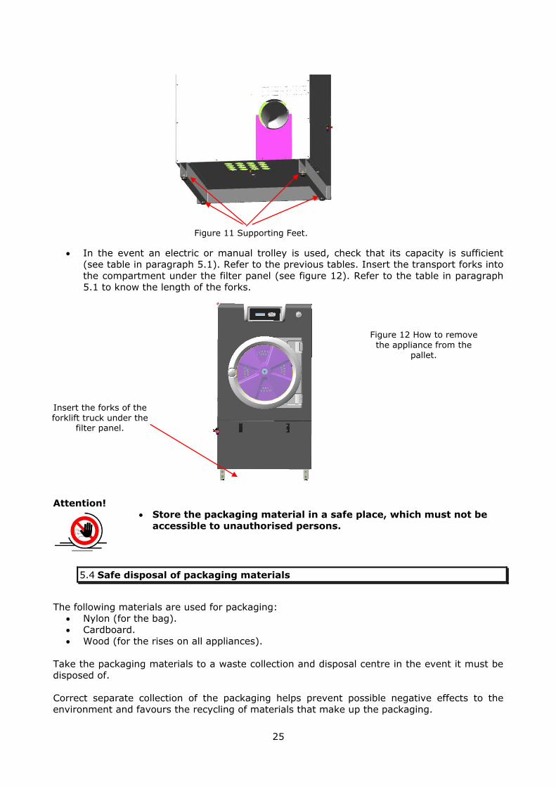
In the event an electric or manual trolley is used, check that its capacity is sufficient (see table in paragraph 5.1). Refer to the previous tables. Insert the transport forks into
the compartment under the filter panel (see figure 12). Refer to the table in paragraph 5.1 to know the length of the forks.
Attention! Store the packaging material in a safe place, which must not be
accessible to unauthorised persons.
5.4 Safe disposal of packaging materials
The following materials are used for packaging:
Nylon (for the bag). Cardboard.
Wood (for the rises on all appliances).
Take the packaging materials to a waste collection and disposal centre in the event it must be disposed of.
Correct separate collection of the packaging helps prevent possible negative effects to the environment and favours the recycling of materials that make up the packaging.
Insert the forks of the forklift truck under the
filter panel.
Figure 11 Supporting Feet.
Figure 12 How to remove the appliance from the
pallet.

26
Illegal disposal of the packaging involves the application of administrative sanctions provided by law.
Refer to the WEEE European Directive regarding the recovery of parts (only for countries that are part of the European Community).
To dismantle the single parts and take them to a differentiated collection centre, refer to the
cataloguing groups of the individual parts. If required, the cataloguing groups can be found on the website: www.euwas.org
5.5 Operations to be carried out before installation
Once you have removed the packaging, check the data indicated on the appliance
identification plate. Figure 13 shows the position of the identification plate.
5.5.1 Serial number plate for models with electric or steam heating.
Serial number of the appliance
Company name
Power Supply Voltage
Year and month of manufacture
Total electric absorption
IP protection rate of the appliance
Total power
Motor power
Model
Appliance type approvals.
Figure 14 Identification plate found on the last page of the manual and on the rear panel of the appliance in models with electric and steam heating.
Figure 13
Rear view. Position of the identification plate.

27
5.5.2 Serial number plate for models with gas heating.
Besides the plate described in figure 14, there is the one described in figure 16.
Attention!
Do not power the appliances with voltage and frequency outside
the values stated. Check that the electric power supply data correspond with the
electric energy supply values. The offset allowed is ±10% of the rated voltage stated on the
label and ± 1 Hz of the nominal frequency stated on the label.
Serial number of the appliance
Company name
Power supply voltage and frequency
Gross weight and dimensions
Signature confirming quality checks performed
Net weight and volume of the packaging
Model
Inspector's signature
Figure 15 Identification plate found on the appliance packaging in models with electric and steam heating.
Serial number of the appliance
Company name
Power Supply Voltage
Year and month of manufacture
Total electric absorption
IP protection rate of the appliance
Heat capacity
Motor power
Model
Type of gas appliance.
Figure 16 Identification plate found on the last page of the manual, on the rear panel of
the appliance and on the cardboard in models with gas heating.
Gas surveillance body code.
Gas appliance PIN.
Category
Nation
Gas type.
28
5.6 Installation and assembly
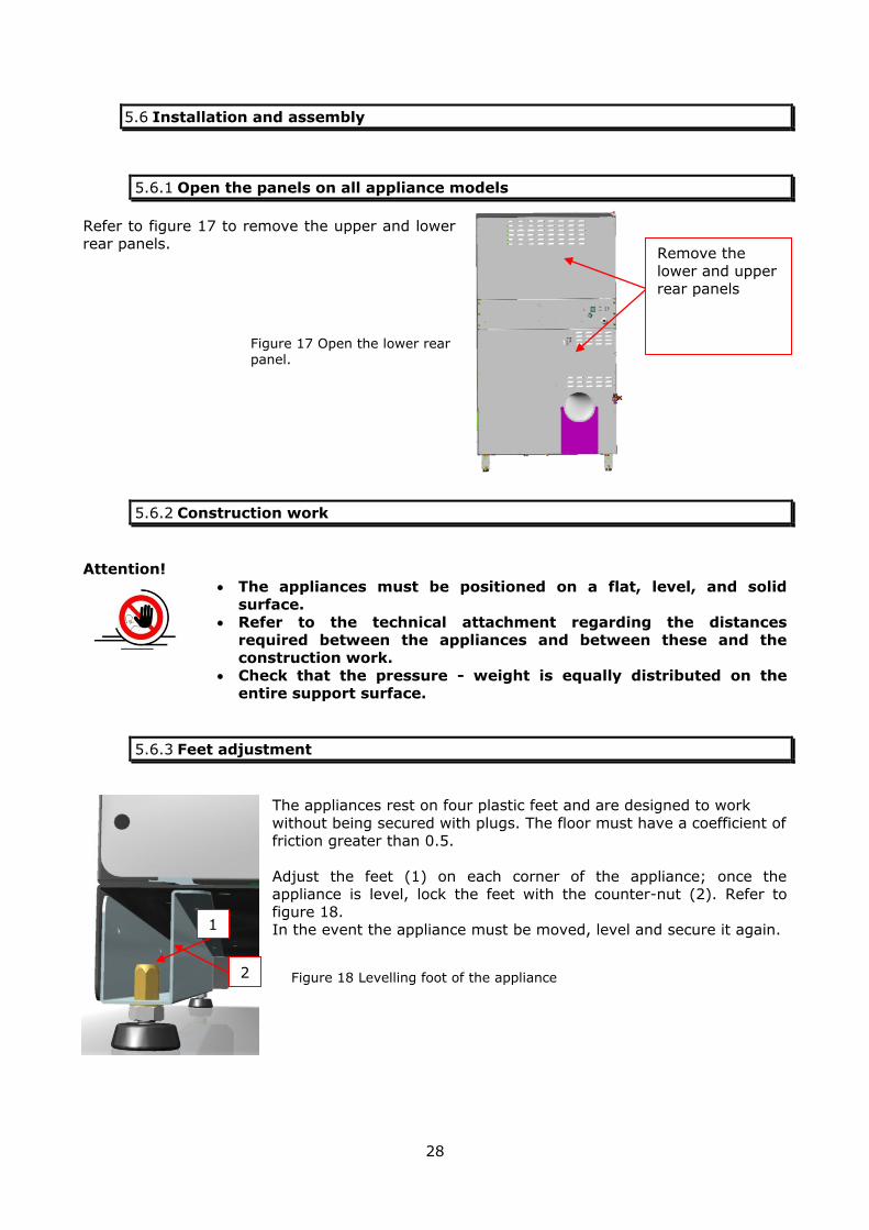
5.6.1 Open the panels on all appliance models
Refer to figure 17 to remove the upper and lower rear panels.
5.6.2 Construction work
Attention! The appliances must be positioned on a flat, level, and solid
surface. Refer to the technical attachment regarding the distances
required between the appliances and between these and the construction work.
Check that the pressure - weight is equally distributed on the entire support surface.
5.6.3 Feet adjustment
The appliances rest on four plastic feet and are designed to work
without being secured with plugs. The floor must have a coefficient of friction greater than 0.5.
Adjust the feet (1) on each corner of the appliance; once the appliance is level, lock the feet with the counter-nut (2). Refer to
figure 18. In the event the appliance must be moved, level and secure it again.
Remove the
lower and upper rear panels
2 Figure 18 Levelling foot of the appliance
1
Figure 17 Open the lower rear panel.

29
5.7 Connection of the fumes discharge for models with electric and steam
heating
The appliance is supplied with a connection for the evacuation of the fumes. Refer to the table to know the diameters of the connections and the maximum lengths allowed.
Model Maximum length (m) Inner diameter (mm) Kg 11, kg 14 20 (50Hz) 150 Kg 18, kg 24 25 (50Hz) – 30 (60Hz) 200
5.7.1 Increase coefficients for installation of curves and fittings
In designing the fume exhaust duct, keep in mind the number of curves used. Each curve makes you lose metres of length as indicated in the following table.
Curved shape Description r = radius
inner curve, d = pipe diameter
Linear Coefficient, lost pipe length correspondence in meters
90° Curve r = 2d 1.1
45° Curve r = 2d 0.7
90° Curve r = d 1.9
45° Curve r = d 1.1
Corrugated pipe 90° curve
r = 2d 3.2
Corrugated pipe 45° curve
r = 2d 2.0
90° curve in segments
r = 2d 1.2
Westerflex 90° curve
r = 2d 1.2
r = 4d 0.9
Westerflex 45° curve
r = 2d 1.0
r = 4d 0.9
Attention!
The fumes must be taken out to a well-ventilated open area. Do not exceed the maximum length of the exhaust flues indicated
in the table in paragraph 5.7. Avoid narrowing and siphons, which can fill with condensate and
jeopardise suction, after reducing sections or corrosion of the
flue. Avoid horizontal or descending tracts of flue.
30
Provide an outlet for the recovery of condensate in the lowest point of evacuation, only if the total length of the channel exceeds
10 metres in length.
The piping must resist crushing and be free from uprights and gate valves.
If several appliances must be installed without distinct drains, make all necessary arrangements so that the fumes cannot return
into the place of installation through the pipes of the other appliances.
The section of the resulting pipe must be at least equal to the sum of the sections of the individual pipes.
Before connecting several appliances to the same drain, make sure that the pipe coupling has a 30° angle.
Attention!
Maximum temperature of fumes 80°C. The pipe must be resistant against corrosion.
Contact the appliance supplier or manufacturer for sections and distances other than those indicated in the table in paragraph 5.7.
Do not use flues already used for discharges coming from gas, carbon, wood, diesel burners or other sources of energy.
The appliance's mist discharge must be separated from any other
discharge coming from other sources. Provide a distance of 5 cm between the flue discharge channel
and any other object. The piping must be made of rigid metal.
Screws or rivets must not be used for joints, as they protrude inside the pipe.
Use high temperature resistant systems for joints.
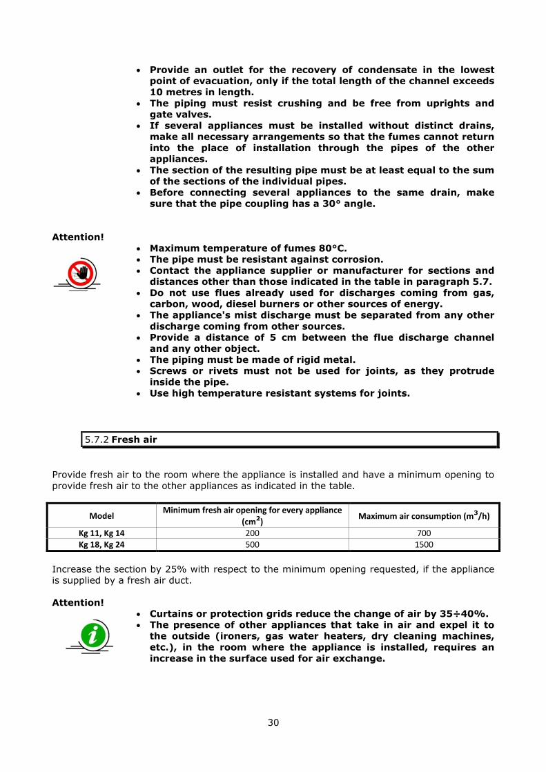
5.7.2 Fresh air
Provide fresh air to the room where the appliance is installed and have a minimum opening to
provide fresh air to the other appliances as indicated in the table.
Model Minimum fresh air opening for every appliance
(cm2) Maximum air consumption (m3/h)
Kg 11, Kg 14 200 700 Kg 18, Kg 24 500 1500
Increase the section by 25% with respect to the minimum opening requested, if the appliance is supplied by a fresh air duct.
Attention!
Curtains or protection grids reduce the change of air by 35÷40%. The presence of other appliances that take in air and expel it to
the outside (ironers, gas water heaters, dry cleaning machines, etc.), in the room where the appliance is installed, requires an
increase in the surface used for air exchange.

31
5.8 Steam supply connection (only where necessary)
The appliance is set-up for a saturated steam inlet
(without presence of air) and dry steam inlet (without presence of condensate) and one
condensate drain with the diameters described in
the technical attachment. Refer to the appliance data plate.
Appliances with steam heating must be installed in
compliance with the local and national laws in force.
The steam supply piping and gate valves and
condensate return must be appropriately dimensioned depending on the steam pressure,
temperature and requirements of the machine
(steam consumption); however, the diameter must not be smaller than the inlet and outlet
attachments onto the appliance.
The appliance is equipped with a steam inlet (see figure 19), into which the steam solenoid valve (EV) supplied must be connected (positioned inside the drum for transport).
The appliance has a condensate outlet to which a trap (SC) must be connected, dimensioned
according to the distance between the outlet and the trap and to the features of the system.
Attention!
The steam intake piping and the condensate return piping can reach very high temperatures, as can all steam and condensate
control, filtering and drain devices. Set-up a suitable protection device against burns.
A fine mesh filter (FL) must be installed upstream from the
solenoid valve to prevent impurities present in the line from
damaging the solenoid valve membrane. A shut-off gate valve must also be installed that is indispensable for performing repairs,
maintenance or emergencies. It is always advisable to assemble a non-return valve downstream
from the trap to prevent condensate from returning. A shut-off gate valve is essential to perform maintenance, repairs or
emergency operations and is a passage indicator that confirms the correct operation of the steam system.
EV
SC
FL
Figure 19 Steam connection

32
5.8.1 Connection diagram of the appliance with steam heating
KEY
Code Description Model Dimensions Notes
SR1 Inlet gate valve 11kg ÷ 14kg ¾” Not supplied
18kg ÷ 24kg 1” Not supplied
SR2 Outlet gate valve All ¾” Not supplied
MN1 Pressure gauge before reducer All - - - Not supplied
MN2 Pressure gauge after reducer All - - - Not supplied
RI Pressure reducer
400 ÷ 600kpa
11kg ÷ 14kg ¾” Not supplied
18kg ÷ 24kg 1” Not supplied
TF1 Corrugated PFTE flexible hose 11kg ÷ 14kg ¾” Not supplied
18kg ÷ 24kg 1” Not supplied
TF2 Corrugated PFTE flexible hose All ¾” Not supplied
FL Mechanical filter 11kg ÷ 14kg ¾” Not supplied
18kg ÷ 24kg 1” Not supplied
EV Steam solenoid valve 11kg ÷ 14kg 1” Supplied
18kg ÷ 24kg 1” Supplied
SCA Heat exchanger inside the
appliance
11kg ÷ 14kg 35 kg/h - - -
18kg ÷ 24kg 60kg/h - - -
SC Condensate trap 11kg ÷ 14kg ¾” Not supplied
18kg ÷ 24kg ¾” Not supplied
IS Inspection 11kg ÷ 14kg ¾” Not supplied
NR Non-return valve 11kg ÷ 14kg ¾” Not supplied
Other elements such as pipe bleeding devices, heat exchangers, pumps for condensate rising,
superheaters and support lungs must be used according to the type of system and appliance performance.
A list of some features of the most used condensate traps is indicated in the figure 20 with the abbreviation SC.
FL EV TF1 RI SR1
SC TF2 IS NR SR2
MN1 MN2
SCA
Figure 20 Steam connection diagram

33
5.8.2 Liquid expansion thermostatic trap
As it does not withhold condensate, it is not subject to freezing. High drain capacity even when
cold. The minimum distance between the dryer output and the trap is 2 metres. It does not accept large steam pressure changes. The flexible element does not accept the presence of
corrosive condensate.
5.8.3 Thermostatic trap
As well as the qualities of the previous type, it has a greater resistance to water hammers and
corrosive condensate. However, it is not recommended where a temperature control is
available.
5.8.4 Steam trap with float
Accepts sudden load and pressure variations. Easily drains the air in the pipes. In case of maintenance or faults, it is simply built and it is easy to repair. Immediate condensate drain.
The float does not support corrosive condensate, water hammers or overheated steam. The
choice must be made according to the operating pressure.
5.8.5 Inverted bucket steam trap
Accepts water hammers and overheated steam. On request, it can withstand corrosive
condensate. Simply built. Its correct operation implies perfect dimensioning. It is slower to respond to pressure and load variations. Should pressure drop, continuous steam passages can
be created.
5.8.6 Thermodynamic steam trap
Smaller dimensions than previous models. Large condensate drain capacity. They have a wide temperature and pressure operating range. They work with overheated steam, even in the
presence of corrosive condensate. Accepts water hammers well. There is no risk of freezing if the drain faces downwards. It does not work with pressure below 0.3 bar and with drain
counter-pressure greater than 80% compared to the inlet pressure.
Attention! Use components suitable for the pressure and temperature of the
steam and condensate. Steam pressure between 0.4 Mpa and 0.6 Mpa corresponds to a
temperature between 142°C and 158°C.
34
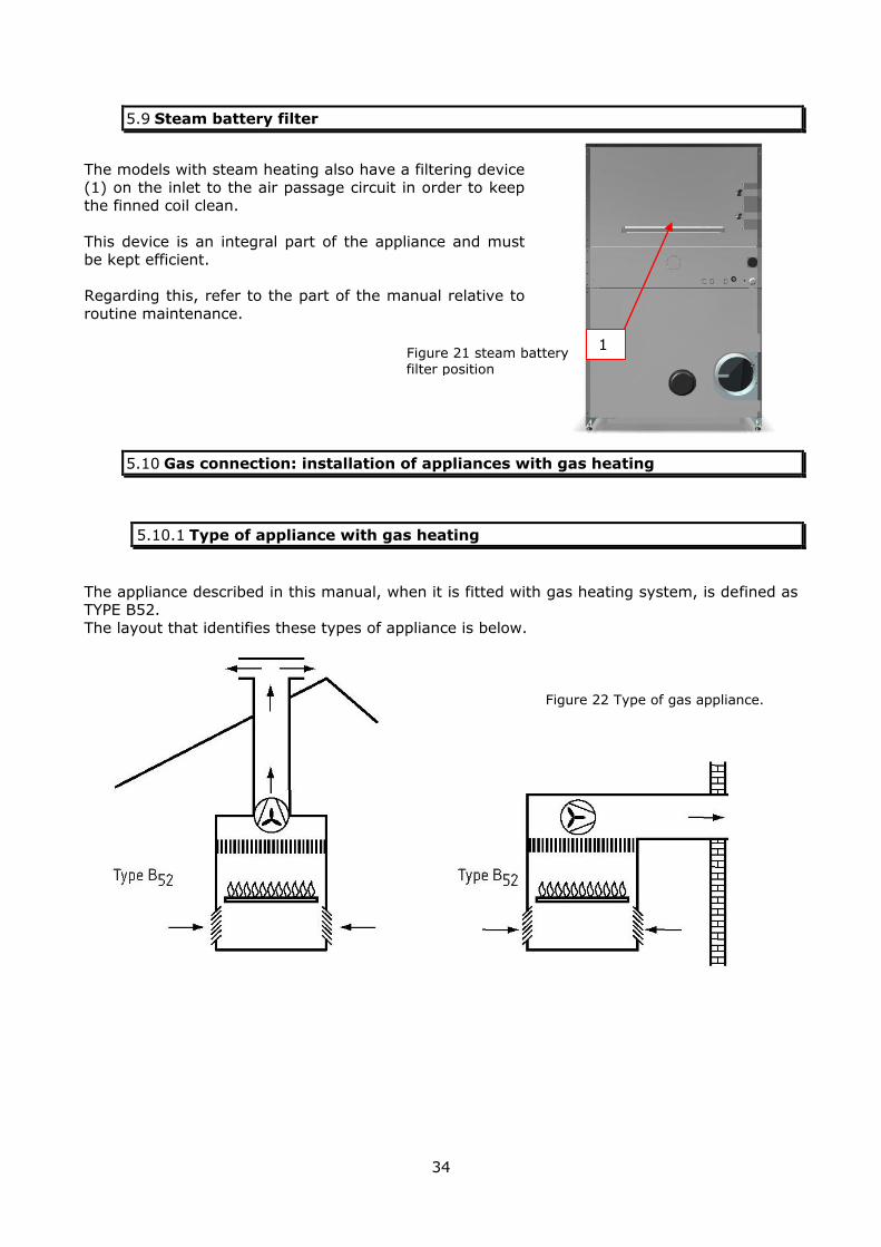
5.9 Steam battery filter
The models with steam heating also have a filtering device
(1) on the inlet to the air passage circuit in order to keep the finned coil clean.
This device is an integral part of the appliance and must be kept efficient.
Regarding this, refer to the part of the manual relative to
routine maintenance.
5.10 Gas connection: installation of appliances with gas heating
5.10.1 Type of appliance with gas heating
The appliance described in this manual, when it is fitted with gas heating system, is defined as TYPE B52.
The layout that identifies these types of appliance is below.
1 Figure 21 steam battery filter position
Figure 22 Type of gas appliance.

35
Attention! Gas appliances must not be installed in the same places where
appliances using solvents that contain perchloretylene (PER) or
chlorofluorocarbons (CFC) are installed. The prohibition is valid for any type of gas.
Attention! Only qualified installers must be contacted for any installation and
maintenance on gas appliances. Do-it-yourself is prohibited.
All gas appliances must be installed in compliance with local and
national laws in force. Before installation check that the distribution conditions, nature
and pressure of the gas and the layout of the appliance are compatible.
The appliance is set-up for operation with the type of gas, the pressure and category indicated
on the serial plate provided: On the last page of this manual.
On the rear central panel of the appliance.
On the appliance packaging.
Attention! Do not power the appliance with different gas and pressures from
those envisioned. Bad combustion deriving from the use of a type of gas different
from that for which the appliance has been calibrated can cause the formation of carbon monoxide, a very toxic gas.
All appliance models are fitted with one drain both for the steam
generated during drying and for the burned gas.

36
5.10.2 Gas tables
Category Group
gas
Reference
gas
Supply
pressures
(mbar)
Ø Nozzle
(mm)
Ø diaphram
(mm)
Burner
pressure
13kW (mbar)
Burner
pressure
18kW (mbar)
Ø Nozzle
(mm)
Ø diaphragm
(mm)
Burner
pressure
13kW (mbar)
Burner
pressure
18kW (mbar)
DK Denmark III1a2H3B/P 1a G110 8 8,00 (*) 28,5 (**) 1,5 2,5 8,00 (*) 28,5 (**) 1,5 2,5
IT Italy III1a2H3+ 1a G110 8 8,00 (*) 28,5 (**) 1,5 2,5 8,00 (*) 28,5 (**) 1,5 2,5
SE Sweden II1a2H ; II2H3B/P 1a G110 8 8,00 (*) 28,5 (**) 1,5 2,5 8,00 (*) 28,5 (**) 1,5 2,5
(*)L=28mm (**) On burner
GD11-14 GD18-24
First family
Category Gas
Group
Reference
gas
Supply
pressures
(mbar)
Ø Nozzle Ø diaphragm Burner
pressure
13kW (mbar)
Burner
pressure
18kW (mbar)
Ø Nozzle Ø diaphragm
(mm)
Burner
pressure
16kW (mbar)
Burner
pressure
24kW (mbar)
AL Albania II2H3B/P ; II2H3P 2H G20 20 3,80 *** 4,7 8,5 4,40 *** 3,8 8,5
AT Austria II2H3B/P 2H G20 20 3,80 *** 4,7 8,5 4,40 *** 3,8 8,5
BE Belgium 2E+ G20 20 3,80 4,5 (determ.) *** 4,40 5,0 8,0(*) ***
BE Belgium 2E+ G25 25 3,80 4,5 (determ.) *** 4,40 5.0 8,0(*) ***
BG Bulgaria II2H3B/P ; II2H3P 2H G20 20 3,80 *** 4,7 8,5 4,40 *** 3,8 8,5
CH Switzerland II2H3B/P ; II2H3+ 2H G20 20 3,80 *** 4,7 8,5 4,40 *** 3,8 8,5
CY Cyprus II2H3B/P ; II2H3+ 2H G20 20 3,80 *** 4,7 8,5 4,40 *** 3,8 8,5
CZ Czech Republic II2H3B/P ; II2H3P ; II2H3+ 2H G20 20 3,80 *** 4,7 8,5 4,40 *** 3,8 8,5
DE Germany 2E G20 20 3,80 *** 4,7 8,5 4,40 *** 3,8 8,5
DE Germany 2LL G25 25 4,20 *** 4,5 8,4 4,80 *** 4,0 9,0
DK Denmark III1a2H3B/P 2H G20 20 3,80 *** 4,7 8,5 4,40 *** 3,8 8,5
EE Estonia II2H3B/P 2H G20 20 3,80 *** 4,7 8,5 4,40 *** 3,8 8,5
ES Spain II2H3+ 2H G20 20 3,80 *** 4,7 8,5 4,40 *** 3,8 8,5
FI Finland I2H ; II2H3B/P 2H G20 20 3,80 *** 4,7 8,5 4,40 *** 3,8 8,5
FR France 2E+ G20 20 3,80 4,5 (determ.) *** 4,40 5,0 8,0(*) ***
FR France 2E+ G25 25 3,80 4,5 (determ.) *** 4,40 5.0 8,0(*) ***
GB United Kingdom II2H3+ ; II2H3P 2H G20 20 3,80 *** 4,7 8,5 4,40 *** 3,8 8,5
GR Greece II2H3B/P; II2H3+ 2H G20 20 3,80 *** 4,7 8,5 4,40 *** 3,8 8,5
HU Hungary 2H G20 20 3,80 *** 4,7 8,5 4,40 *** 3,8 8,5
HU Hungary 2S G25.1 25 4,20 *** 5,0 9,5 4,80 *** 4,0 9,5
HR Croatia II2H3B/P ; II2H3P 2H G20 20 3,80 *** 4,7 8,5 4,40 *** 3,8 8,5
IE Ireland II2H3+ ; II2H3P 2H G20 20 3,80 *** 4,7 8,5 4,40 *** 3,8 8,5
IS Iceland *** *** *** *** *** *** *** *** *** *** *** ***
IT Italy III1a2H3+ 2H G20 20 3,80 *** 4,7 8,5 4,40 *** 3,8 8,5
LT Lithuania II2H3B/P ; II2H3P 2H G20 20 3,80 *** 4,7 8,5 4,40 *** 3,8 8,5
LU Luxembourg II2H3P; II2E3P 2H G20 20 3,80 *** 4,7 8,5 4,40 *** 3,8 8,5
LV Latvia II2H 2H G20 20 3,80 *** 4,7 8,5 4,40 *** 3,8 8,5
MK Rep. of Macedonia II2H3B/P ; II2H3P 2H G20 20 3,80 *** 4,7 8,5 4,40 *** 3,8 8,5
MT Malta I3B ; I3B/P *** *** *** *** *** *** *** *** *** *** ***
NL Netherlands II2L3B/P 2L G25 25 4,20 *** 4,5 8,4 4,80 *** 4,0 9,0
NO Norway II2H3B/P 2H G20 20 3,80 *** 4,7 8,5 4,40 *** 3,8 8,5
PL Poland 2E G20 20 3,80 *** 4,7 8,5 4,40 *** 3,8 8,5
PL Poland 2Ls G2.350 13 5,00 *** 4,0 7,0 5,80 *** 3,0 7,0
PT Portugal II2H3+ 2H G20 20 3,80 *** 4,7 8,5 4,40 *** 3,8 8,5
RO Romania II2H3B/P ; II2E3B/P 2H/2E G20 20 3,80 *** 4,7 8,5 4,40 *** 3,8 8,5
SE Sweden II1a2H ; II2H3B/P 2H G20 20 3,80 *** 4,7 8,5 4,40 *** 3,8 8,5
SI Slovenia II2H3B/P ; II2H3P ; II2H3+ 2H G20 20 3,80 *** 4,7 8,5 4,40 *** 3,8 8,5
SK Slovakia II2H3B/P ; II2H3P; II2H3+ 2H G20 20 3,80 *** 4,7 8,5 4,40 *** 3,8 8,5
TR Turkey II2H3B/P ; II2H3+ 2H G20 20 3,80 *** 4,7 8,5 4,40 *** 3,8 8,5
(*) before diaphragm
II2ELL3B/P
II2E+3+
I2E+ ; I3+
II2HS3B/P ; I2HS ; I3B/P
II2E3B/P ; II2ELs3B/P
GD11-14 GD18-24
Second family

37
Category Group
gas
Reference
gas
Supply
pressures
(mbar)
Ø Nozzle
(mm)
Ø diaphragm
(mm)
Burner
pressure
13kW (mbar)
Burner
pressure
18kW (mbar)
Ø Nozzle
(mm)
Ø diaphragm
(mm)
Burner
pressure
16kW (mbar)
Burner
pressure
24kW (mbar)
AL Albania 3B/P G30/G31 30 2,20 *** 11,1 22,1 2,60 *** 8,5 21,0
AL Albania 3P G31 37 2,10 *** 17,5 36,4 2,40 *** 15,0 35,2
AT Austria II2H3B/P 3B/P G30/G31 50 2,20 *** 11,1 22,1 2,60 *** 8,5 21,0
BE Belgium I2E+ ; I3+ 3+ G30/G31 28-30/37 2,10 *** 14,0/17,5 28,0/36,4 2,40 *** 11,0/15,0 27,5/35,2
BG Bulgaria 3B/P G30/G31 30 2,20 *** 11,1 22,1 2,60 *** 8,5 21,0
BG Bulgaria 3P G31 37 2,10 *** 17,5 36,4 2,40 *** 15,0 35,2
CH Switzerland 3B/P G30/G31 50 2,20 *** 11,1 22,1 2,60 *** 8,5 21,0
3+ G30/G31 28-30/37 2,10 *** 14,0/17,5 28,0/36,4 2,40 *** 11,0/15,0 27,5/35,2
CY Cyprus II2H3B/P ; II2H3+ 3B/P G30/G31 30 2,20 *** 11,1 22,1 2,60 *** 8,5 21,0
CY Cyprus 3+ G30/G31 28-30/37 2,10 *** 14,0/17,5 28,0/36,4 2,40 *** 11,0/15,0 27,5/35,2
CZ Czech Republic 3B/P G30/G31 30 2,20 *** 11,1 22,1 2,60 *** 8,5 21,0
CZ Czech Republic 3P G31 37 2,10 *** 17,5 36,4 2,40 *** 15,0 35,2
CZ Czech Republic 3+ G30/G31 28-30/37 2,10 *** 14,0/17,5 28,0/36,4 2,40 *** 11,0/15,0 27,5/35,2
DE Germany II2ELL3B/P 3B/P G30/G31 50 2,20 *** 11,1 22,1 2,60 *** 8,5 21,0
DK Denmark III1a2H3B/P 3B/P G30/G31 30 2,20 *** 11,1 22,1 2,60 *** 8,5 21,0
EE Estonia II2H3B/P 3B/P G30/G31 30 2,20 *** 11,1 22,1 2,60 *** 8,5 21,0
ES Spain II2H3+ 3+ G30/G31 28-30/37 2,10 *** 14,0/17,5 28,0/36,4 2,40 *** 11,0/15,0 27,5/35,2
FI Finland I2H ; II2H3B/P 3B/P G30/G31 30 2,20 *** 11,1 22,1 2,60 *** 8,5 21,0
FR France II2E+3+ 3+ G30/G31 28-30/37 2,10 *** 14,0/17,5 28,0/36,4 2,40 *** 11,0/15,0 27,5/35,2
GB United Kingdom 3+ G30/G31 28-30/37 2,10 *** 14,0/17,5 28,0/36,4 2,40 *** 11,0/15,0 27,5/35,2
GB United Kingdom 3P G31 37 2,10 *** 17,5 36,4 2,40 *** 15,0 35,2
GR Greece 3B/P G30/G31 30 2,20 *** 11,1 22,1 2,60 *** 8,5 21,0
GR Greece 3+ G30/G31 28-30/37 2,10 *** 14,0/17,5 28,0/36,4 2,40 *** 11,0/15,0 27,5/35,2
HU Hungary II2HS3B/P; I2HS ; I3B/P 3B/P G30/G31 30 2,20 *** 11,1 22,1 2,60 *** 8,5 21,0
HR Croatia 3B/P G30/G31 30 2,20 *** 11,1 22,1 2,60 *** 8,5 21,0
HR Croatia 3P G31 37 2,10 *** 17,5 36,4 2,40 *** 15,0 35,2
IE Ireland 3+ G30/G31 28-30/37 2,10 *** 14,0/17,5 28,0/36,4 2,40 *** 11,0/15,0 27,5/35,2
IE Ireland 3P G31 37 2,10 *** 17,5 36,4 2,40 *** 15,0 35,2
IS Iceland *** *** *** *** *** *** *** *** *** *** *** ***
IT Italy III1a2H3+ 3+ G30/G31 28-30/37 2,10 *** 14,0/17,5 28,0/36,4 2,40 *** 11,0/15,0 27,5/35,2
LT Lithuania 3B/P G30/G31 30 2,20 *** 11,1 22,1 2,60 *** 8,5 21,0
LT Lithuania 3P G31 37 2,10 *** 17,5 36,4 2,40 *** 15,0 35,2
LU Luxembourg II2H3P; II2E3P 3P G31 50 2,10 *** 17,5 36,4 2,40 *** 15,0 35,2
LV Latvia II2H *** *** *** *** *** *** *** *** *** *** ***
MK Rep. of Macedonia 3B/P G30/G31 30 2,20 *** 11,1 22,1 2,60 *** 8,5 21,0
MK Rep. of Macedonia 3P G31 37 2,10 *** 17,5 36,4 2,40 *** 15,0 35,2
MT Malta 3B G30 30 2,20 *** 11,1 22,1 2,60 *** 8,5 21,0
MT Malta 3B/P G30/G31 30 2,20 *** 11,1 22,1 2,60 *** 8,5 21,0
NL Netherlands II2L3B/P 3B/P G30/G31 30 2,20 *** 11,1 22,1 2,60 *** 8,5 21,0
NO Norway II2H3B/P 3B/P G30/G31 30 2,20 *** 11,1 22,1 2,60 *** 8,5 21,0
PL Poland II2E3B/P ; II2ELs3B/P 3B/P G30/G31 30 2,20 *** 11,1 22,1 2,60 *** 8,5 21,0
PT Portugal II2H3+ 3+ G30/G31 28-30/37 2,10 *** 14,0/17,5 28,0/36,4 2,40 *** 11,0/15,0 27,5/35,2
RO Romania II2H3B/P ; II2E3B/P 3B/P G30/G31 30 2,20 *** 11,1 22,1 2,60 *** 8,5 21,0
SE Sweden II1a2H ; II2H3B/P 3B/P G30/G31 30 2,20 *** 11,1 22,1 2,60 *** 8,5 21,0
SI Slovenia 3B/P G30/G31 30 2,20 *** 11,1 22,1 2,60 *** 8,5 21,0
SI Slovenia 3P G31 37 2,10 *** 17,5 36,4 2,40 *** 15,0 35,2
SI Slovenia 3+ G30/G31 28-30/37 2,10 *** 14,0/17,5 28,0/36,4 2,40 *** 11,0/15,0 27,5/35,2
SK Slovakia 3B/P G30/G31 30 2,20 *** 11,1 22,1 2,60 *** 8,5 21,0
SK Slovakia 3P G31 37 2,10 *** 17,5 36,4 2,40 *** 15,0 35,2
SK Slovakia 3+ G30/G31 28-30/37 2,10 *** 14,0/17,5 28,0/36,4 2,40 *** 11,0/15,0 27,5/35,2
TR Turkey 3B/P G30/G31 30 2,20 *** 11,1 22,1 2,60 *** 8,5 21,0
TR Turkey 3+ G30/G31 30/37 2,10 *** 14,0/17,5 28,0/36,4 2,40 *** 11,0/15,0 27,5/35,2
II2H3B/P ; II2H3P
II2H3B/P ; II2H3P; II2H3+
II2H3B/P ; II2H3P
II2H3B/P ; II2H3P ; II2H3+
II2H3+ ; II2H3P
II2H3B/P; II2H3+
II2H3B/P; II2H3P
II2H3B/P ; II2H3P; II2H3+
II2H3B/P ; II2H3+
GD11-14 GD18-24
Third family
II2H3B/P ; II2H3+
II2H3+ ; II2H3P
II2H3B/P ; II2H3P
II2H3B/P ; II2H3P
I3B ; I3B/P

38
5.10.3 Flue evacuation gas heating version
See the tables in paragraph 5.7 for reference to the lengths allowed according to the different
appliance model.
The flue must have a smooth internal surface and be made of suitable material to resist the temperatures of the outlet fumes.
Attention!
The Standards provide detailed instructions regarding the type and quality of the materials to be used for the piping and their
accessories, for smoke channels, the chimneys and the flues. Comply with the provisions and Local Standards in force.
Attention! A load heavier than the appliance nominal load jeopardises the air
circuit. The filter in the drain channel is an integral part of the appliance.
Checking the air/fumes circuit is a very important operation for safety reasons.
Check the air - fumes circuit after every intervention, even partial, on the system or the appliance.
Any appliance where a burner is running absorbs the air
necessary for combustion and emits fumes. An opening is mandatory to withdraw outdoor air. This must have
a minimum surface as stated in paragraph 5.7.
39
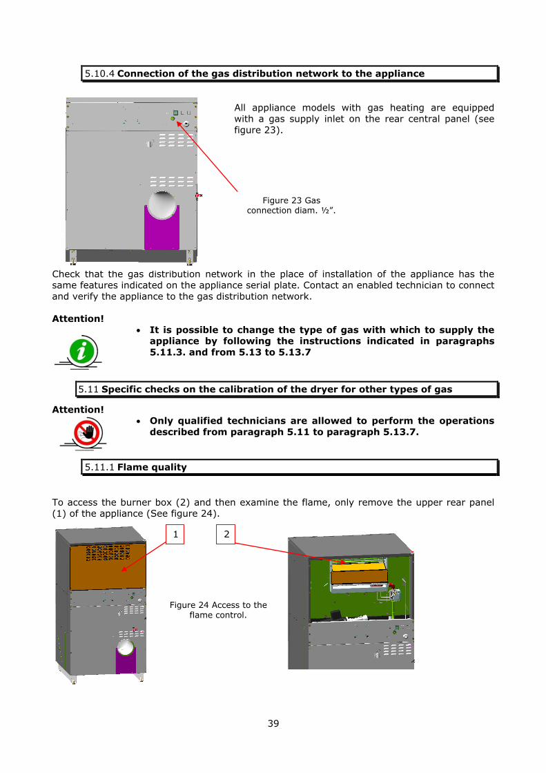
5.10.4 Connection of the gas distribution network to the appliance
All appliance models with gas heating are equipped with a gas supply inlet on the rear central panel (see
figure 23).
Check that the gas distribution network in the place of installation of the appliance has the same features indicated on the appliance serial plate. Contact an enabled technician to connect
and verify the appliance to the gas distribution network.
Attention!
It is possible to change the type of gas with which to supply the appliance by following the instructions indicated in paragraphs
5.11.3. and from 5.13 to 5.13.7
5.11 Specific checks on the calibration of the dryer for other types of gas
Attention! Only qualified technicians are allowed to perform the operations
described from paragraph 5.11 to paragraph 5.13.7.
5.11.1 Flame quality
To access the burner box (2) and then examine the flame, only remove the upper rear panel (1) of the appliance (See figure 24).
1 2
Figure 23 Gas connection diam. ½”.
Figure 24 Access to the flame control.
40
The flame must be taut and light blue. If it is irregular and yellowish, the appliance requires an intervention by the installation technician. Refer to the paragraph relative to routine and
extraordinary maintenance for the indications on how to proceed with flame regulation.
Attention!
If one of the following cases occurs, call the after-sales assistance immediately:
When soot, dirt or stains are identified in the appliance or in the immediate vicinity due, for example, to possible
burning. When hissing or knocking sounds are heard upon
activation. If the gate valves on the supply line do not function
correctly, e.g. if they do not close the appliance supply
hermetically. If safety devices, such as alarms AL6, AL7, AL8, AL9,
AL10 or manual reset thermostat ST1, ST3, or ST4 require repeated interventions.
5.11.2 What to do if you smell gas
All combustible gases must have a characteristic smell, to allow the detection of their presence in case of leaks, before reaching dangerous levels.
In the presence of this characteristic smell, act as follows: Open doors and windows to air the room as much as possible.
DO NOT TURN ON THE LIGHT Switch all the flames off immediately.
Close the gate valve or the main supply valve of the appliance or appliances. Do not smoke or ignite naked flames.
Do not activate any type of electrical appliance or telephone.
Keep the main gate valve closed and check that other secondary gate valves are also closed.
If the system is powered with G30 and G31 liquid gas (commonly called GPL or LPG) and an accidental leak occurs, this initially tends to stratify on the ground as it is heavier than air.
In all cases, behave as described previously and call the technical after-sales assistance.
5.11.3 Instructions on how to modify the appliance calibration for other types
of gas.
Appliances with gas heating are supplied with a kit for the replacement of the type of gas with which the appliance can be powered.
The kit consists of the following material: Approved nozzles
Valve outlet diaphragm for FR/BE Mechanical interface block
Fitting gaskets
Screws for diaphragm assembly
Adhesive kits for updating data
plates. Burner inlet diaphragm for 1st family
gases
Replace the nozzle positioned on the right of the burner, making sure that the diameter stated in the new nozzle to be assembled corresponds to the table in paragraph 5.10.1.

41
5.11.4 Special cases: FR/BE diaphragm installation and 1st family gases
For installations with gas heating in countries such as France and Belgium or to use 1st family
gases, it is necessary to install the corresponding diaphragm in addition to the nozzle (see gas tables).
1. Approved nozzles 2. FR-BE diaphragm
3. Mechanical interface block 4. Fitting gaskets
5. Valve body 6. Burner inlet diaphragm for 1st family
gases
Attention!
Update the serial plate on the appliance rear and on the last page
of this manual. The adhesives stating the new features must entirely cover the
original indications in order to avoid any misunderstandings.
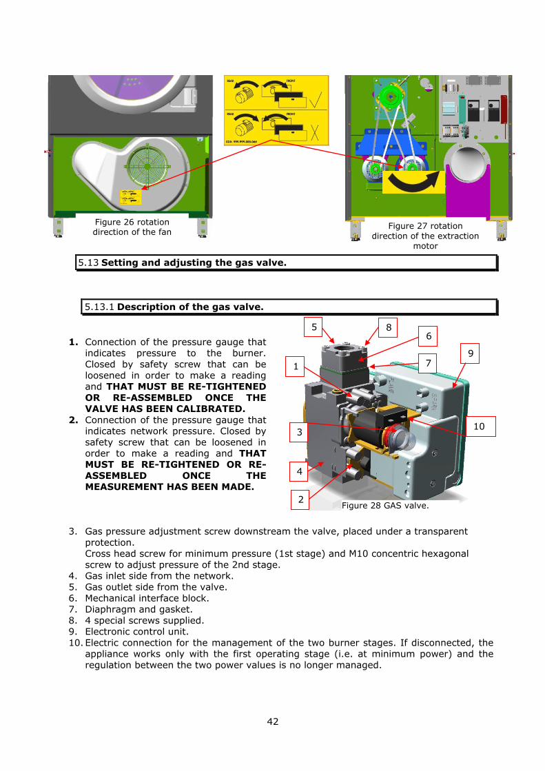
5.12 Check the rotation direction of the extractor.
Start a drying cycle with the appliance empty (and gas inlet gate valve closed) and check the
rotation direction of the extraction motor: Make sure the fan rotates clockwise (from the front of the appliance, removing the
filtering mesh) (see figure 26). Make sure the extraction motor from the back of the appliance (removing the lower rear
panel) rotates anti-clockwise (see figure 27).
Otherwise, immediately stop the appliance, disconnect the power supply sources and invert two of the three phases of the appliance power supply. Then, restore the power supply sources
and check again.
In appliances with SINGLE or 2-PHASE electric power supply, it is not necessary to perform
this check, regardless of the type of heating used.
A visual check of the rotation direction of the extraction motor is however possible by controlling that it rotates as indicated by the adhesive label positioned on the machine in
proximity of the fan, accessible by opening the filter inspection door (see figure 26).
1
2 3
4
5
Figure 25 - assembly of the diaphragm.
6
42
5.13 Setting and adjusting the gas valve.
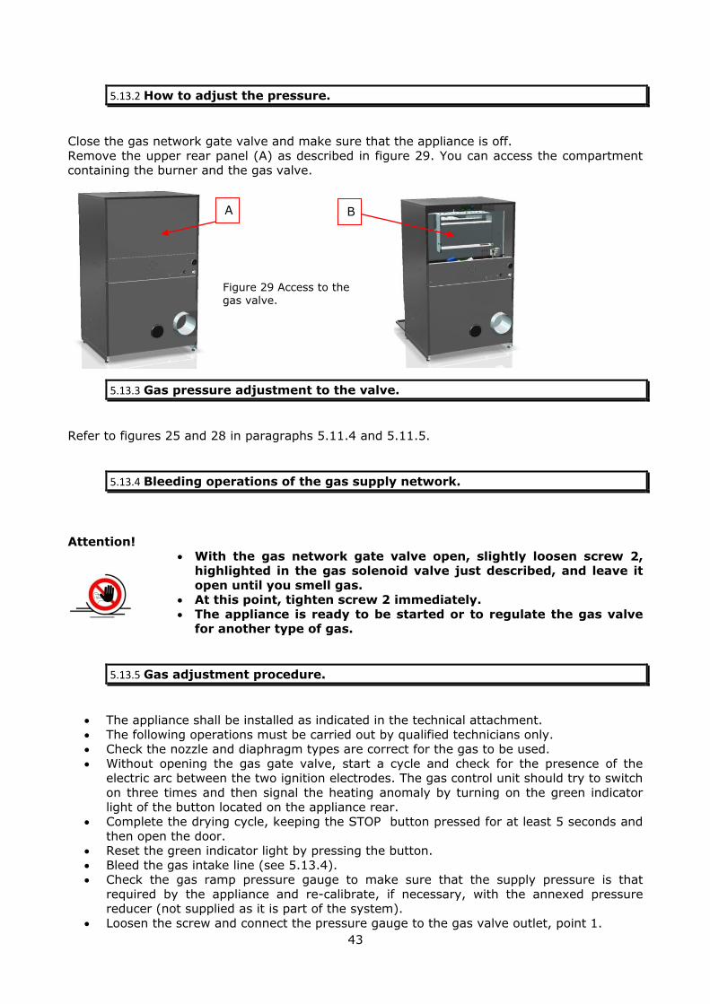
5.13.1 Description of the gas valve.
1. Connection of the pressure gauge that indicates pressure to the burner.
Closed by safety screw that can be
loosened in order to make a reading and THAT MUST BE RE-TIGHTENED
OR RE-ASSEMBLED ONCE THE VALVE HAS BEEN CALIBRATED.
2. Connection of the pressure gauge that indicates network pressure. Closed by
safety screw that can be loosened in order to make a reading and THAT
MUST BE RE-TIGHTENED OR RE-
ASSEMBLED ONCE THE MEASUREMENT HAS BEEN MADE.
3. Gas pressure adjustment screw downstream the valve, placed under a transparent
protection. Cross head screw for minimum pressure (1st stage) and M10 concentric hexagonal
screw to adjust pressure of the 2nd stage. 4. Gas inlet side from the network.
5. Gas outlet side from the valve.
6. Mechanical interface block. 7. Diaphragm and gasket.
8. 4 special screws supplied. 9. Electronic control unit.
10. Electric connection for the management of the two burner stages. If disconnected, the appliance works only with the first operating stage (i.e. at minimum power) and the
regulation between the two power values is no longer managed.
1
5 6
7
8
9
4
10
Figure 28 GAS valve.
4
3
2
Figure 26 rotation direction of the fan
Figure 27 rotation
direction of the extraction motor
43
5.13.2 How to adjust the pressure.
Close the gas network gate valve and make sure that the appliance is off.
Remove the upper rear panel (A) as described in figure 29. You can access the compartment containing the burner and the gas valve.
5.13.3 Gas pressure adjustment to the valve.
Refer to figures 25 and 28 in paragraphs 5.11.4 and 5.11.5.
5.13.4 Bleeding operations of the gas supply network.
Attention!
With the gas network gate valve open, slightly loosen screw 2, highlighted in the gas solenoid valve just described, and leave it
open until you smell gas. At this point, tighten screw 2 immediately.
The appliance is ready to be started or to regulate the gas valve for another type of gas.
5.13.5 Gas adjustment procedure.
The appliance shall be installed as indicated in the technical attachment.
The following operations must be carried out by qualified technicians only. Check the nozzle and diaphragm types are correct for the gas to be used.
Without opening the gas gate valve, start a cycle and check for the presence of the electric arc between the two ignition electrodes. The gas control unit should try to switch
on three times and then signal the heating anomaly by turning on the green indicator
light of the button located on the appliance rear. Complete the drying cycle, keeping the STOP button pressed for at least 5 seconds and
then open the door. Reset the green indicator light by pressing the button.
Bleed the gas intake line (see 5.13.4). Check the gas ramp pressure gauge to make sure that the supply pressure is that
required by the appliance and re-calibrate, if necessary, with the annexed pressure reducer (not supplied as it is part of the system).
Loosen the screw and connect the pressure gauge to the gas valve outlet, point 1.
A B
Figure 29 Access to the gas valve.

44
Remove protection cover indicated in point 3 of figure 28. Open the gas gate valve, start a cycle and approximately calibrate the valve so that the
flame is taut, blue and without yellow/orange parts using a 10 mm fixed spanner and a
Phillips screwdriver. End the drying cycle as previously described.
Close the gas gate valve. Move the pressure gauge on the screw relative to the valve inlet pressure (after having
loosened it) to position 2 and close the outlet one in position 1. Open the gas gate valve.
Start a drying cycle and check that the inlet pressure with the appliance running at nominal heating power is correct and, if necessary, adjust via the pressure reducer of
the gas ramp. End the drying cycle as previously described.
Close the gas gate valve.
Re-position the pressure gauge on the valve outlet screw (after loosening it) in position 1 after closing the inlet one in position 2.
Open the gas gate valve and start a cycle. Regulate the maximum pressure (with 10 mm hexagonal box wrench) as per the gas
table (paragraph 5.10.1) attached to this manual. Regulate the minimum pressure (with cross head spanner) as per the gas table attached
to this manual. To switch from maximum pressure (second stage) to minimum pressure (first stage),
insert or remove the "bridge rectifier" connected to position 10 of figure 27. Connection
is guaranteed by a safety screw. Regulate the two pressure values to comply with the values requested simultaneously.
It is recommended to seal the adjustment screw with a drop of sealing wax. Reinstall the transparent plastic protection (position 3).
5.13.6 Precautions to be taken for all models
Attention!
For correct adjustment of the gas, the valve pressure value, which can be measured in position 2, must be equal to the nominal
pressure stated in the table and required for the various appliances.
Check sealing of the gas circuit upstream the valve, as described below.
Pressurise the gas circuit by opening the gas gate valve, close the gate valve upstream the gas ramp pressure gauge for 2 minutes
and check the stability of the pressure. It MUST NOT drop.
Check the joints using specific leak detector foam, in the event of maintenance or regulation of the valve for other types of gas.
Control the correct heating operation by reaching the set temperature and changeover the valve from first to second stage
and vice-versa. At the end of the regulation procedure, restore all screws and
protection devices previously removed or loosened. The appliance is live during the calibration and regulation
procedure. Pay attention to the accessible parts.
The burner and surrounding parts can reach dangerous temperatures. Pay special attention.
Make sure the data labels state the adjusted data and no longer the original data.
Draw up a service report that states the following.
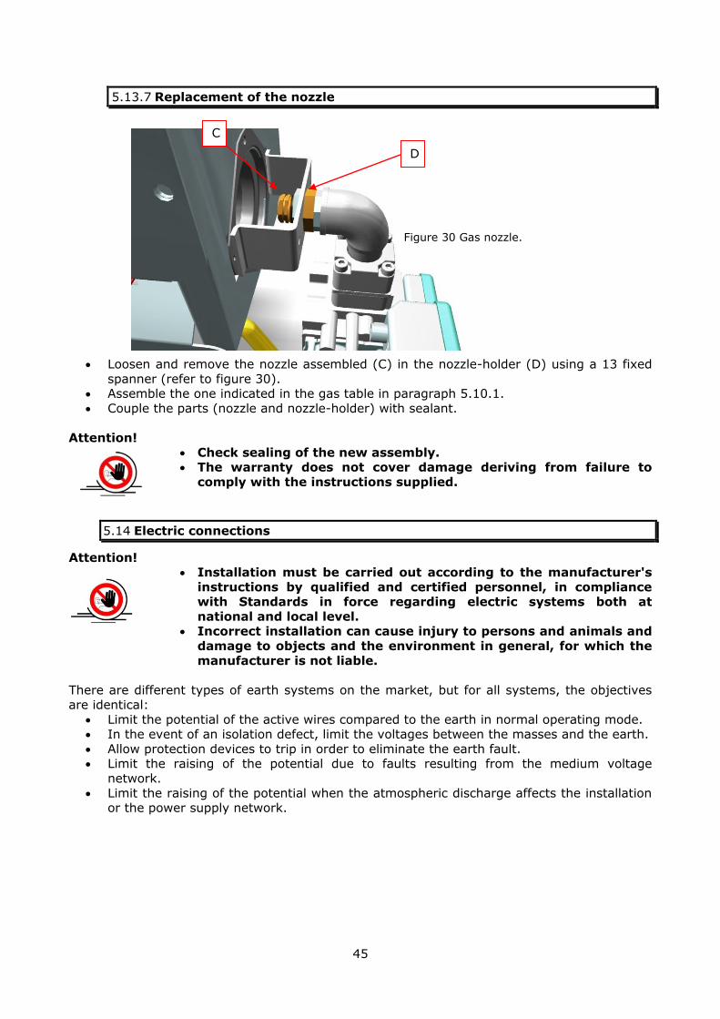
45
5.13.7 Replacement of the nozzle
Loosen and remove the nozzle assembled (C) in the nozzle-holder (D) using a 13 fixed
spanner (refer to figure 30). Assemble the one indicated in the gas table in paragraph 5.10.1.
Couple the parts (nozzle and nozzle-holder) with sealant.
Attention!
Check sealing of the new assembly. The warranty does not cover damage deriving from failure to
comply with the instructions supplied.
5.14 Electric connections
Attention! Installation must be carried out according to the manufacturer's
instructions by qualified and certified personnel, in compliance with Standards in force regarding electric systems both at
national and local level. Incorrect installation can cause injury to persons and animals and
damage to objects and the environment in general, for which the
manufacturer is not liable.
There are different types of earth systems on the market, but for all systems, the objectives are identical:
Limit the potential of the active wires compared to the earth in normal operating mode. In the event of an isolation defect, limit the voltages between the masses and the earth.
Allow protection devices to trip in order to eliminate the earth fault. Limit the raising of the potential due to faults resulting from the medium voltage
network.
Limit the raising of the potential when the atmospheric discharge affects the installation or the power supply network.
C
D
Figure 30 Gas nozzle.

46
Some examples.
NATION LV Public Distribution
Network (neutral point connection).
User systems powered at
low voltage.
Specific earth
system.
GERMANY TN-C TN-C and TT yes
AUSTRALIA TN-C TN-C yes
JAPAN TT TT yes
UNITED KINGDOM TN-C TN-C or TN-S NO
IRELAND TN TT yes
ITALY TT TT yes
BELGIUM TT TT yes
SWITZERLAND TN TN-C or TN-S yes
FRANCE TT TT yes
CHINA TT TT yes
SPAIN TT TT yes
PORTUGAL TT TT yes
NORWAY IT IT NO
Attention!
The appliance described in this manual is set-up for a TT earth system.
Certification of the system must be made by a qualified
technician, who verifies and certifies its correct design and operation.
For appliances with steam supply, make sure that the electric connection cable cannot come into contact with the steam supply
pipe or condensate collection/recovery pipe. The differential switch, where required, must be of class B.
There is a clamp on the rear part of the appliance for the connection of the equipotential,
which must be performed in compliance with the Laws in force. The manufacturer declines any
liability for failure to comply with this accident-prevention standard.
Identify the symbol shown in figure 31.
This clamp must be connected to the same clamp of the other appliances present in the
vicinity and must be then connected to the earth connection via a protective earth circuit alternative to the earth wire supplied with the socket.
Before introducing the power supply cable, check that the cable has a bend that is lower than
the appliance inlet or terminal board, in a way that any drops of condensation onto the cable do not come into contact with the electrical connections, thanks to this cable (refer to figure
32). Power the appliance in compliance with its plate data and with the available distribution
system.
Use cable gland A assembled on the rear panel of the appliance to insert the power supply cable. Pass it in cable gland B of the component box and block the cable, after having
connected the cables to the disconnector switch supplied with the appliance.
Figure 31 Equipotential clamp symbol.

47
Figure 33 Power supply cable passage.
Attention! The earth cable must be longer than the other wires by at least 2
cm.
5.14.1 Special features of the electrical connection
Attention!
During the connection of several appliances with “speed variator” option, identify the phase that powers the inverters (single-
phase) and connect them alternately on the 3 phases available to distribute the load evenly.
Figure 32 Power supply cable inlet
B
A

48
Attention! Before connecting the appliance electrically, check that the power
supply voltage matches with the voltage indicated on the serial
number plate. The appliance makes use of voltages different than the rated
voltage but with the limits indicated on the wiring diagram.
5.14.1.1 Power supply connection 380-400-415 3~ + N
Figure 34 shows the connection of the appliance for the versions with power supply: three-phase 380-400-415 VAC WITH NEUTRAL
5.14.1.2 Power supply connection 380-400-415-440 3~ or 220-230-240 3~.
Figure 35 shows the connection of the appliance for the versions with power supply: three-phase 380-400-415 VAC WITHOUT NEUTRAL
three-phase 220-230-240 VAC
N L1 L2 L3 PE
Figure 34 Internal view of the appliance, which shows
the connection of the electric power supply network to the disconnector switch clamps.
N = Neutral L1 = Phase
L2 = Phase L3 = Phase PE = Earth
L1 L2 L3 PE
Figure 35 Internal view of the appliance, which shows the connection of the electric
power supply network to the disconnector switch clamps.
L1 = Phase
L2 = Phase L3 = Phase
PE = Earth
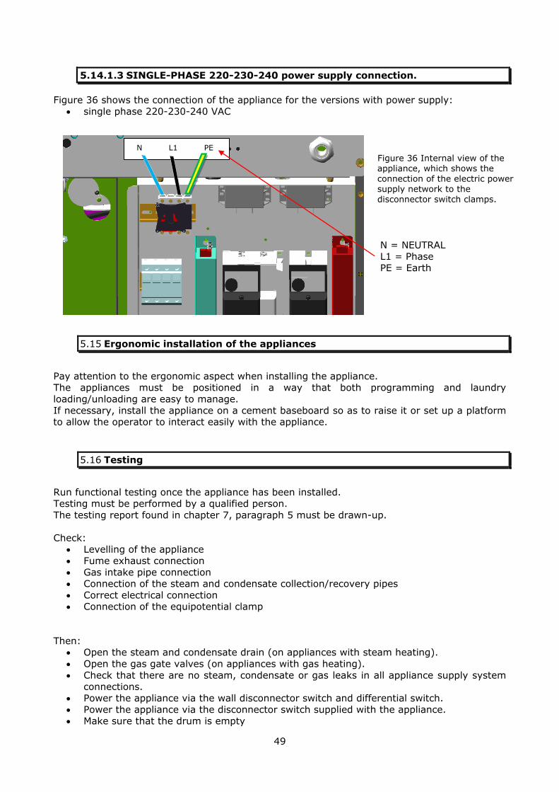
49
5.14.1.3 SINGLE-PHASE 220-230-240 power supply connection.
Figure 36 shows the connection of the appliance for the versions with power supply:
single phase 220-230-240 VAC
5.15 Ergonomic installation of the appliances
Pay attention to the ergonomic aspect when installing the appliance. The appliances must be positioned in a way that both programming and laundry
loading/unloading are easy to manage.
If necessary, install the appliance on a cement baseboard so as to raise it or set up a platform to allow the operator to interact easily with the appliance.
5.16 Testing
Run functional testing once the appliance has been installed. Testing must be performed by a qualified person.
The testing report found in chapter 7, paragraph 5 must be drawn-up.
Check: Levelling of the appliance
Fume exhaust connection
Gas intake pipe connection Connection of the steam and condensate collection/recovery pipes
Correct electrical connection Connection of the equipotential clamp
Then: Open the steam and condensate drain (on appliances with steam heating).
Open the gas gate valves (on appliances with gas heating).
Check that there are no steam, condensate or gas leaks in all appliance supply system connections.
Power the appliance via the wall disconnector switch and differential switch. Power the appliance via the disconnector switch supplied with the appliance.
Make sure that the drum is empty
N L1 PE
Figure 36 Internal view of the appliance, which shows the connection of the electric power supply network to the disconnector switch clamps.
N = NEUTRAL L1 = Phase PE = Earth
50
Once this is done, run a high temperature drying cycle with very damp rags.
This is to remove traces of products used during mechanical processing of the appliance.
When these checks have been performed with positive result, reposition all protections and
panels that were previously removed. Train all operators that will be interacting with the appliance during the entire functioning
period. At this point, the appliance can be used by the operators.
Attention!
The warranty does not cover damages resulting from incorrect installation.
5.17 Storage and protection during intervals between normal use periods
Follow the indications below in the event the appliance must undergo long periods of downtime:
Disconnect the appliance from the power supply.
Disconnect the plug. Close the gas gate valves and the steam and condensate recovery gate valves if the
appliance has this type of heating. Drain the condensate in the appliance.
Dry the drum and the door gasket.
Leave the door open and if possible cover the appliance to protect it from dust. Keep the appliance in a closed place, which complies with environmental conditions.
5.18 Re-packaging to prevent damage during transport
Attention! Use the original packaging and wooden feet if the appliance must
be transferred.
5.19 Information assignment (users, operators, maintenance experts)
Attention! The instructions contained in this manual must be disclosed to the
personnel that interact with the appliance.

51
5.19.1 Location of the instructions
These instructions are supplied with the appliance and are attached to the packaging in an
adhesive bag, which identifies its contents. This manual must accompany the appliance in every step of its life cycle.
Attention!
Any person using this appliance must read and demonstrate to have understood this user manual.
The appliance must only be used by trained persons. Store this manual in a place which can be easily accessed for
future reference. If this appliance is transferred to another owner, this manual
must be supplied with the appliance.
5.20 Warranty
The warranty covers a period of twelve (12) months, from the date of purchase of the appliance, or of an integral part of it.
The warranty consists in replacing any failed parts for ascertained manufacturing causes and it is applied directly by your supplier.
The purchaser is in charge of labour as well as delivery, packaging, and shipping costs, and must bear the risks of transport.
According to the warranty conditions, damaged pieces must be returned CARRIAGE PAID, once
all the data regarding the model, serial number and defect of the appliance on which the
component was assembled have been communicated. The warranty does not apply to appliances that have suffered damages due to negligence,
incorrect connection, unsuitable installation, failure to comply with assembly or user instructions, and, however, having been altered by unauthorised personnel. Moreover, the
warranty does not apply if the serial number has been altered, deleted or removed or is unknown.
The warranty does not cover the following material, subject to normal wear, such as:
Belts;
Solenoid valve membrane; Gaskets and rubber parts in general;
Electric and electronic components, such as motor, coils, contactors, heaters, circuit boards, inverters.
6 OPERATING INSTRUCTIONS
Attention!
Any person using this appliance must read this user manual. The appliance must only be used by trained persons.
The appliance cannot be used by persons (including children) with
reduced physical, sensory, mental capacities or with little experience or knowledge, unless they have been examined or
trained regarding the use of the appliance by suitably trained staff that is responsible for their safety.

52
Children should be supervised to make sure they do not play with the appliance.
The appliance has not been designed to be used in environments
subject to the ATEX Standard, relative to explosive atmospheres. The appliance has not been designed to disinfect laundry.
Before performing any cleaning or maintenance operations, make sure that the steam supply and return gate valves (in the
appliances with this type of heating) are closed and that the master switch is off.
Keep flammable liquids away from the appliance. Keep cleaning and soap products away from the appliance and
locked in a cabinet.
Attention!
The manufacturer is not liable for damage to fabrics dried using an inappropriate program.
The manufacturer is not liable for failure to comply with the indications stated on the labels of the garments or of soaps or
additives. Replace the labels on the appliance if they become illegible.
The manufacturer is not liable for labels that have been removed or replaced.
Comply with all local laws relative to safety.
6.1 Chemical hazard
Attention! The appliance cannot handle laundry that has been in contact with
or soaked in flammable substances. The decomposition of some chemical products in appliances
heated directly (especially with gas burners), such as certain solvents used for dry cleaning, can produce toxic fumes.
6.2 Operating in safe conditions
Check that the laundry trolleys are lower than the door lower limit. Do not allow the trolleys to strike the door, causing damage.
Attention! To prevent spontaneous combustion, the load of laundry must be
removed as soon as the drying cycle has ended. The laundry must be removed for the same reason if the appliance
stops after a power cut.
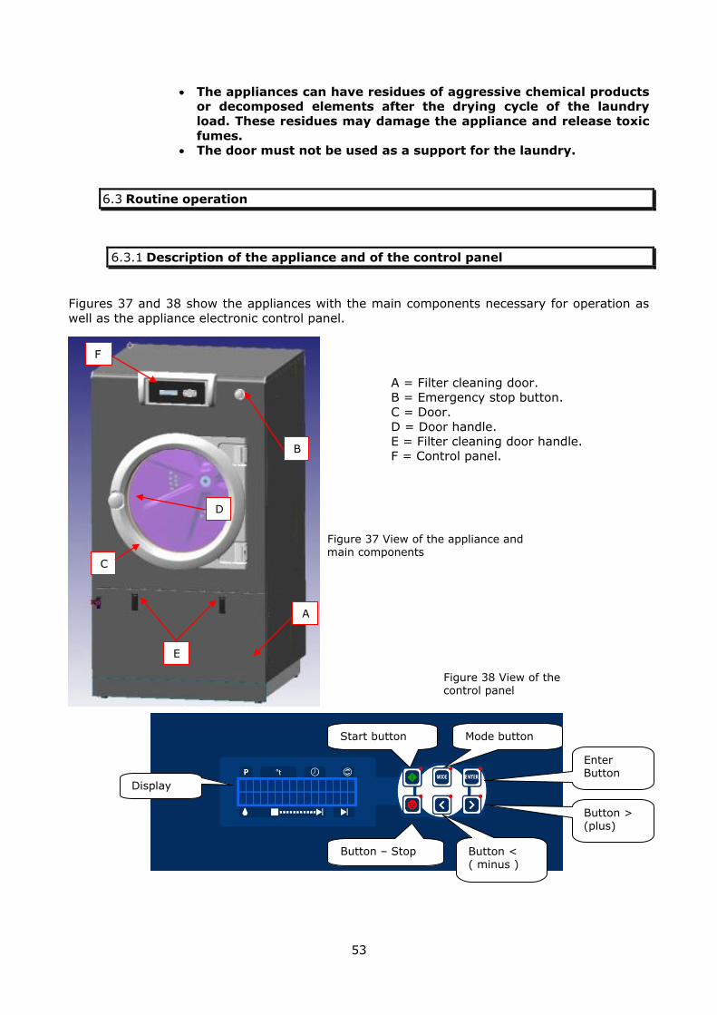
53
Figure 37 View of the appliance and main components
Figure 38 View of the control panel
The appliances can have residues of aggressive chemical products or decomposed elements after the drying cycle of the laundry
load. These residues may damage the appliance and release toxic
fumes. The door must not be used as a support for the laundry.
6.3 Routine operation
6.3.1 Description of the appliance and of the control panel
Figures 37 and 38 show the appliances with the main components necessary for operation as
well as the appliance electronic control panel.
F
A
A = Filter cleaning door. B = Emergency stop button.
C = Door.
D = Door handle. E = Filter cleaning door handle. F = Control panel.
C
B
E
D
Button > (plus)
Button < ( minus )
Enter Button
Mode button Start button
Button – Stop
Display
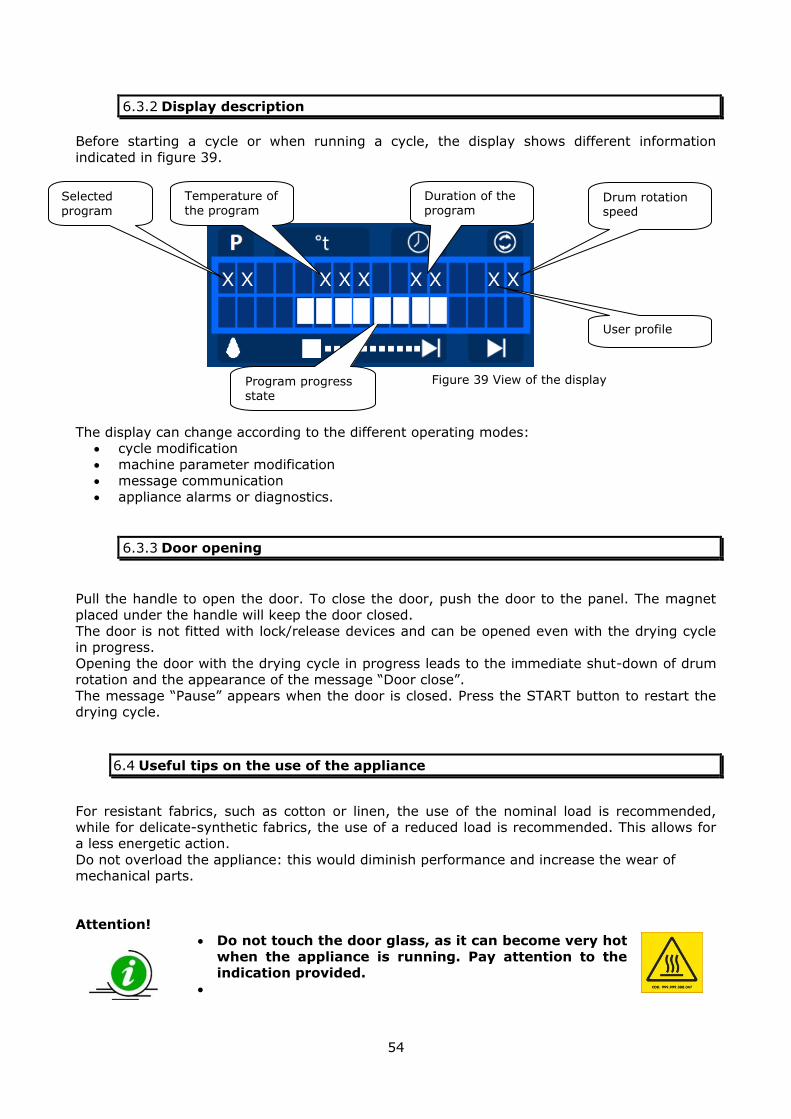
54
Figure 39 View of the display
6.3.2 Display description
Before starting a cycle or when running a cycle, the display shows different information
indicated in figure 39.
The display can change according to the different operating modes:
cycle modification machine parameter modification
message communication
appliance alarms or diagnostics.
6.3.3 Door opening
Pull the handle to open the door. To close the door, push the door to the panel. The magnet
placed under the handle will keep the door closed.
The door is not fitted with lock/release devices and can be opened even with the drying cycle in progress.
Opening the door with the drying cycle in progress leads to the immediate shut-down of drum rotation and the appearance of the message “Door close”.
The message “Pause” appears when the door is closed. Press the START button to restart the drying cycle.
6.4 Useful tips on the use of the appliance
For resistant fabrics, such as cotton or linen, the use of the nominal load is recommended, while for delicate-synthetic fabrics, the use of a reduced load is recommended. This allows for
a less energetic action.
Do not overload the appliance: this would diminish performance and increase the wear of mechanical parts.
Attention! Do not touch the door glass, as it can become very hot
when the appliance is running. Pay attention to the indication provided.
Selected
program
Temperature of
the program
Duration of the program
Drum rotation speed
Program progress state
X X X X X X X X X
User profile

55
6.4.1 Symbols (tags) applied on the fabrics
Symbol Basic symbols
Wet washing: the tub is the symbol for wet washing.
Chlorine bleaching: the chlorine bleaching symbol is a triangle.
Ironing: the shape of an iron is the symbol for ironing.
Professional textile care.
Professional wet washing.
Drying with rotary drum dryer: a square containing a circle is the symbol for drying with
rotary drum dryer.
Symbol Additional symbols
Not admitted treatment: in addition to the 5 previous symbols, the St. Andrew's cross
positioned on the symbol means that the treatment indicated by that particular symbol must not be performed.
Moderate treatment: in addition to the first 5 symbols, the bar under the tub or the circle indicates that the treatment must be carried out moderately complying with the treatment corresponding to the same symbol without bar.
Very moderate treatment: in addition to the 5 symbols, the interrupted bar under the tub
indicates a very moderate washing treatment.
Symbol Washing operations
Maximum temperature: 95°C, normal mechanical action.
Normal rinse, normal spin.
Maximum temperature: 95°C, reduced mechanical action.
Cool down rinse (due to gradual introduction of cold water), reduced spin.
Maximum temperature: 70°C, normal mechanical action.
Normal rinse, normal spin.
Maximum temperature: 60°C, normal mechanical action.
Normal rinse, normal spin.
Maximum temperature: 60°C, reduced mechanical action. Cool down rinse (due to gradual introduction of cold water) reduced spin.
Maximum temperature: 50°C, reduced mechanical action. Cool down rinse (due to gradual introduction of cold water), reduced spin.
Maximum temperature: 40°C, reduced mechanical action. Cool down rinse (due to gradual introduction of cold water) reduced spin.
Maximum temperature: 40°C, considerably reduced mechanical action.
Normal rinse, normal spin, do not wring.
Maximum temperature: 40°C, considerably reduced mechanical action. Normal rinse, reduced spin.
Hand wash only, do not machine wash - maximum temperature 30°C
Handle with care
Do not wash in water.
Handle with care when wet.
Symbol Drying by rotary drum dryer
Drying by rotary drum dryer allowed.
Normal drying program
Drying by rotary drum dryer allowed. Low temperature drying program
Do not dry with rotary drum dryer
Symbol Natural Drying
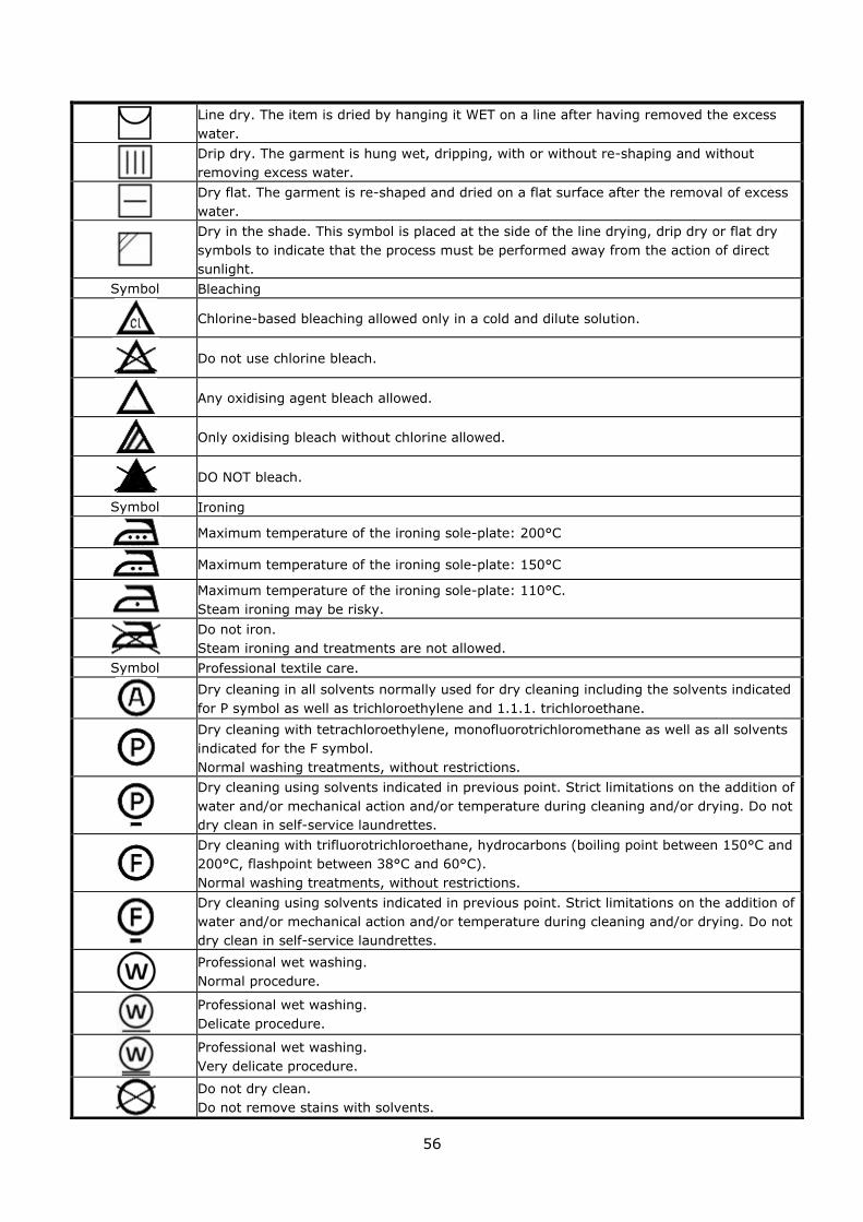
56
Line dry. The item is dried by hanging it WET on a line after having removed the excess
water.
Drip dry. The garment is hung wet, dripping, with or without re-shaping and without
removing excess water.
Dry flat. The garment is re-shaped and dried on a flat surface after the removal of excess
water.
Dry in the shade. This symbol is placed at the side of the line drying, drip dry or flat dry
symbols to indicate that the process must be performed away from the action of direct
sunlight.
Symbol Bleaching
Chlorine-based bleaching allowed only in a cold and dilute solution.
Do not use chlorine bleach.
Any oxidising agent bleach allowed.
Only oxidising bleach without chlorine allowed.
DO NOT bleach.
Symbol Ironing
Maximum temperature of the ironing sole-plate: 200°C
Maximum temperature of the ironing sole-plate: 150°C
Maximum temperature of the ironing sole-plate: 110°C.
Steam ironing may be risky.
Do not iron.
Steam ironing and treatments are not allowed.
Symbol Professional textile care.
Dry cleaning in all solvents normally used for dry cleaning including the solvents indicated
for P symbol as well as trichloroethylene and 1.1.1. trichloroethane.
Dry cleaning with tetrachloroethylene, monofluorotrichloromethane as well as all solvents
indicated for the F symbol.
Normal washing treatments, without restrictions.
Dry cleaning using solvents indicated in previous point. Strict limitations on the addition of
water and/or mechanical action and/or temperature during cleaning and/or drying. Do not
dry clean in self-service laundrettes.
Dry cleaning with trifluorotrichloroethane, hydrocarbons (boiling point between 150°C and
200°C, flashpoint between 38°C and 60°C).
Normal washing treatments, without restrictions.
Dry cleaning using solvents indicated in previous point. Strict limitations on the addition of
water and/or mechanical action and/or temperature during cleaning and/or drying. Do not
dry clean in self-service laundrettes.
Professional wet washing.
Normal procedure.
Professional wet washing.
Delicate procedure.
Professional wet washing.
Very delicate procedure.
Do not dry clean.
Do not remove stains with solvents.

57
6.5 Preparing for a drying program
Before starting a drying cycle:
Check the drum is empty and clean. Load the laundry with the same features (type of fabric) and the same drying
requirements.
Check the labels on every item and follow the indications provided. Before drying any garment, make sure that buttons, zips, clips and buckles face inwards.
Make sure pockets are empty. Do not put laundry into the machine that has been cleaned, wet, washed or stain-
removed with flammable or explosive materials. Proceed by hand washing first. Open the steam and condensate drain/recovery gate valves (for appliances with this
type of heating). Open the gas gate valves (for appliances with this type of heating).
Power the appliance. Check that the display switches on and wait a few seconds for the cycle selection screen to appear.
Select the cycle using the “<” or “>” buttons according to that stated on the labels of
the garments to dry. Close the door and press the START button.
See the table below for the amount of laundry to load.
Drum model/volume Kg11/275dm3 Kg14/350dm
3 Kg18/450dm
3 Kg24/600dm
3
Maximum load capacity (kg) of dry
laundry (to be washed) 15 19 25 33
Maximum load capacity (kg) of wet
laundry (washed and spun) 30 38 50 66
6.6 Function of the control panel keys
Symbol Name Description
START
Cycle start and bypass of the drying cycle sectors button .
STOP Cycle stop button
MODE
Button used to enter and exit the menu address or display information during execution of the program.
MINUS
Button used to change menu item and decrease the displayed
value.
PLUS
Button used to change menu item and increase the displayed value.
ENTER
Button used to confirm the displayed value and enter the item
in the displayed menu.

58
6.7 Automatic execution of a program
The electronic control is already supplied with 10 preset drying cycles, but which can be
customised.
On pressing the START button, the electronic control performs the phases required for the
selected drying cycle. The basic drying cycle sequence includes: 1 heating-drying module (up to 3 modules can be programmed)
cooling phase anti-crease phase
Every phase of the drying cycle can have a specific drum movement and temperature
depending on the type of fabric to treat.
6.8 Starting diagram of a drying cycle
Gw i z 1 . XX
XXXX XX
Switch-on
01 120 C 3 1
1 / 3
Start message
with FW version
display
Program
number
Program
temperature
Duration of the first
program module
Drum rotation
speed
N° module /
N° modules.
Cycle selection
Door
closed?
NO
Display: Close door
YES
Start
selected
cycle
Enter or
mode
pressed?
NO
The cycle
continues
normally and
the
advancement
bar shortens.
01 120 C 3 1
1 / 3
Cycle duration, partials
flash
(eighths of the total time)
Temperature
read by
probe T1
End Cy c l e
A nt i p . X :X X: XX
CD=150 s TDC=25 ° C
NMOD=1 ON
Cooling time
Cooling
temperature
Anti-crease
duration
START
See programming paragraphs

59
Attention! Before opening, always make sure that the drum is at a standstill
and that the internal temperature has dropped below 40°C.
End of cycle: carry out the following operations Leave the door open.
Disconnect power to the appliance via the master switch. Close the gas, the steam and condensate recovery/drain cocks (on the appliances with
this type of heating). Isolate the appliance from the electrical mains.
Attention!
Do not leave the appliance unnecessarily powered by the mains.
Switch the appliance master switch OFF when it is not being used.
6.8.1 Cycle sequence with 3 drying modules (basic version)
This sequence is shown below with the operation block diagram in the basic version (without T2 probe on the drain and without humidity probe).
First drying module
Cycle start Once the time of the first module is
elapsed, it passes to the subsequent
module
Powers the finishing function for
the time set on F
Second drying module
Once the time of the second
module is elapsed, it passes to
the subsequent module
Powers the finishing function
for the time set on F
Third drying module
Once the time of the third
sector is elapsed, it passes to
the cooling phase.
Cooling phase, once the time set on CD is elapsed or when the TCD
temperature is reached, the cycle ends and the anti-crease phase starts
Anti-crease phase, once the time set on AT has elapsed or when the door is opened,
the appliance stops any activity and waits for the execution of a new cycle.
Powers the finishing function
for the time set on F
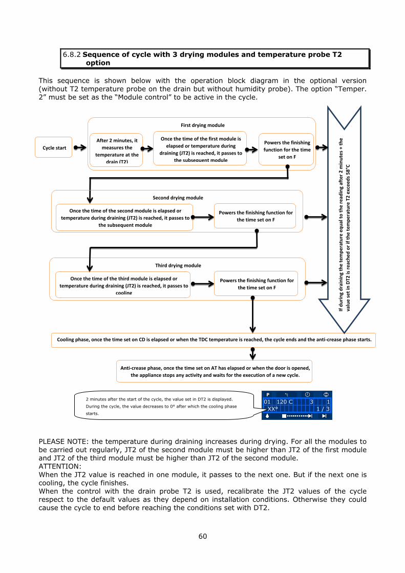
60
6.8.2 Sequence of cycle with 3 drying modules and temperature probe T2
option
This sequence is shown below with the operation block diagram in the optional version
(without T2 temperature probe on the drain but without humidity probe). The option “Temper. 2” must be set as the “Module control” to be active in the cycle.
PLEASE NOTE: the temperature during draining increases during drying. For all the modules to
be carried out regularly, JT2 of the second module must be higher than JT2 of the first module and JT2 of the third module must be higher than JT2 of the second module.
ATTENTION:
When the JT2 value is reached in one module, it passes to the next one. But if the next one is cooling, the cycle finishes.
When the control with the drain probe T2 is used, recalibrate the JT2 values of the cycle respect to the default values as they depend on installation conditions. Otherwise they could
cause the cycle to end before reaching the conditions set with DT2.
First drying module
Cycle start
After 2 minutes, it
measures the
temperature at the
drain (T2)
Once the time of the first module is
elapsed or temperature during
draining (JT2) is reached, it passes to
the subsequent module
Powers the finishing
function for the time
set on F
Second drying module
Once the time of the second module is elapsed or
temperature during draining (JT2) is reached, it passes to
the subsequent module
Powers the finishing function for
the time set on F
Third drying module
Once the time of the third module is elapsed or
temperature during draining (JT2) is reached, it passes to
cooling
Powers the finishing function for
the time set on F
Cooling phase, once the time set on CD is elapsed or when the TDC temperature is reached, the cycle ends and the anti-crease phase starts.
Anti-crease phase, once the time set on AT has elapsed or when the door is opened,
the appliance stops any activity and waits for the execution of a new cycle.
01 120 C 3 1
XX° 1 / 3
2 minutes after the start of the cycle, the value set in DT2 is displayed.
During the cycle, the value decreases to 0° after which the cooling phase
starts.
If d
uri
ng
dra
inin
g th
e t
em
pe
ratu
re e
qu
al t
o t
he
re
ad
ing
afte
r 2
min
ute
s +
the
valu
e s
et
in D
T2 is
re
ach
ed
or
if t
he
te
mp
era
ture
T2
exc
ee
ds
58
°C
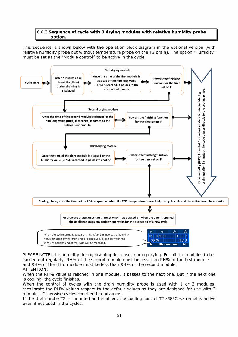
61
6.8.3 Sequence of cycle with 3 drying modules with relative humidity probe
option.
This sequence is shown below with the operation block diagram in the optional version (with
relative humidity probe but without temperature probe on the T2 drain). The option “Humidity” must be set as the “Module control” to be active in the cycle.
PLEASE NOTE: the humidity during draining decreases during drying. For all the modules to be carried out regularly, RH% of the second module must be less than RH% of the first module
and RH% of the third module must be less than RH% of the second module. ATTENTION:
When the RH% value is reached in one module, it passes to the next one. But if the next one
is cooling, the cycle finishes. When the control of cycles with the drain humidity probe is used with 1 or 2 modules,
recalibrate the RH% values respect to the default values as they are designed for use with 3 modules. Otherwise cycles could end in advance.
If the drain probe T2 is mounted and enabled, the cooling control T2>58°C -> remains active even if not used in the cycles.
First drying module
Cycle start
After 2 minutes, the
humidity (RH%)
during draining is
displayed
Once the time of the first module is
elapsed or the humidity value
(RH%) is reached, it passes to the
subsequent module
Powers the finishing
function for the time
set on F
Second drying module
Once the time of the second module is elapsed or the
humidity value (RH%) is reached, it passes to the
subsequent module.
Powers the finishing function
for the time set on F
Third drying module
Once the time of the third module is elapsed or the
humidity value (RH%) is reached, it passes to cooling
Powers the finishing function
for the time set on F
Cooling phase, once the time set on CD is elapsed or when the TCD temperature is reached, the cycle ends and the anti-crease phase starts
Anti-crease phase, once the time set on AT has elapsed or when the door is opened,
the appliance stops any activity and waits for the execution of a new cycle.
01 120 C 3 1
XX% 1 / 3
When the cycle starts, it appears_ _ %. After 2 minutes, the humidity
value detected by the drain probe is displayed, based on which the
modules and the end of the cycle will be managed.
If t
he
hu
mid
ity
(RH
%)
inte
nd
ed
fo
r th
e la
st m
od
ule
is d
ete
cte
d d
uri
ng
dra
inin
g (a
fte
r 2
min
ute
s), t
he
cyc
le p
asse
s d
ire
ctly
to
th
e c
oo
ling
ph
ase
.

62
6.8.4 Description of standard programs supplied with the appliance
Cycles 1 to 5 are set with 1 module (they can be increased up to 3) while cycles 6 to 10 have 3
modules. The drying processed is timed. The default cycles are displayed in detail below (the
relative values which change in modules 2 and 3 are shown in brackets).
Cycle
N°
Drying Cooling Anti-crease
Tem
p.
( °
C )
Du
rati
on
( M
in.
)
Dru
m
Ro
t.
sp
eed
( S
ec.
)
Dru
m
pau
se
( S
ec.
)
JT2
DT2
T2
JR
H%
F
Mo
du
le
co
ntr
ol
Du
rati
on
( M
in.
)
Tem
p.
( °
C )
N.
of
mo
du
les
Du
rati
on
( M
in.
)
Ro
t.
ro
t.
( S
ec.
)
Dru
m
pau
se
( S
ec.
)
1 110 30 5 40 2 40°C 15°C Value read 70% 0 TIME 240 50 1 0 40 200
2 120 30 5 40 2 40°C 15°C Value read 70% 0 TIME 240 50 1 0 40 200
3 130 30 5 40 2 40°C 15°C Value read 70% 0 TIME 240 50 1 0 40 200
4 90 30 5 40 2 40°C 15°C Value read 70% 0 TIME 240 50 1 0 40 200
5 80 30 5 40 2 40°C 15°C Value read 70% 0 TIME 240 50 1 0 40 200
6 130
(120)
(120)
7 (+20)
(+6)
5 (4)
(3)
40 2 40°C
(45°C)
(50°C)
15°C Value read
70% (40%)
(15%)
0 TIME 240 50 3 20 40 200
7 130
(120)
(120)
7 (+25)
(+6)
5 (4)
(3)
40 2 40°C
(45°C)
(50°C)
15°C Value read
70% (40%)
(15%)
0 TIME 240 50 3 20 40 200
8 130
(130)
(130)
7 (+25)
(+6)
5 (4)
(3)
40 2 40°C
(45°C)
(50°C)
15°C Value read
70% (40%)
(15%)
0 TIME 240 50 3 20 40 200
9 110 (90)
(90)
7 (+16)
(+5)
5 (4)
(3)
40 2 40°C
(45°C)
(50°C)
15°C Value read
70% (40%)
(15%)
0 TIME 240 50 3 20 40 200
10 100 (80)
(80)
7 (+12)
(+5)
5 (4)
(3)
40 2 40°C
(45°C)
(50°C)
15°C Value read
70% (40%)
(15%)
0 TIME 240 50 3 20 40 200
Attention! If the appliance has been re-programmed from the keyboard or
several special functions have been activated, do not refer to the
tables. The manufacturer reserves the right to modify the drying cycles
normally memorised in the appliances at any time.
6.8.5 Description of modified programs
Cycle
N° Drying Cooling Anti-crease
Tem
p.
( °
C )
Du
rati
o
n
( M
in.
)
Dru
m
Ro
t.
sp
eed
( S
ec.
)
Dru
m
pau
se
( S
ec.
)
JT2
DT2
T2
JR
H%
F
Mo
du
le
co
ntr
ol
Du
rati
o
n
( M
in.
)
Tem
p.
( °
C )
N.
of
mo
du
le
s
Du
rati
o
n
( M
in.
)
Ro
t.
ro
t.
( S
ec.
)
Dru
m
pau
se
( S
ec.
)
1
2
3
4
5
6
7
8
9
10
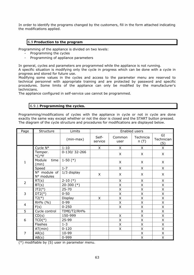
63
In order to identify the programs changed by the customers, fill in the form attached indicating the modifications applied.
6.9 Production to the program
Programming of the appliance is divided on two levels:
- Programming the cycles
- Programming of appliance parameters
In general, cycles and parameters are programmed while the appliance is not running.
A specific situation is modifying only the cycle in progress which can be done with a cycle in
progress and stored for future use. Modifying some values in the cycles and access to the parameter menu are reserved to
technical personnel with appropriate training and are protected by password and specific procedures. Some limits of the appliance can only be modified by the manufacturer's
technicians. The appliance configured in self-service use cannot be programmed.
6.9.1 Programming the cycles.
Programming/modifications of cycles with the appliance in cycle or not in cycle are done exactly the same way except whether or not the door is closed and the START button pressed.
The diagram of the cycle structure and procedures for modifications are displayed below.
Page Structure Limits Enabled users
(min-max) Self-
service Common
user Technicia
n (T)
GI
Technician (S)
1
Cycle N° 1-10 X X X X
Temper.
°C/°F
0-130/ 32-266 X X X
Module time (min)
1-50 (*) X X X
Speed 1-7 X X X
N° module of
N° modules
1/3 display X X X X
2 RT(s) 2-10 (*) X X X
BT(s) 20-300 (*) X X X
3
JT2(°) 25-70 X X X
DT2(°) 0-50 X X X
T2(°) Display X X X X
4 RH% (%) 0-99 X X X
F(s) 0-250 X X X
5 Cycle control TIME/T2/RH% X X
6
CD(s) 150-999 X X X
TCD(°) 25-99 X X X
Flashes 1-3 X X X
7
AT(min) 0-120 X X X
AR(s) 10-99 X X
AB(s) 0-999 X X
(*) modifiable by (S) user in parameter menu.

64
Meaning of items in cycle menu
1
Cycle N° The cycles are identified by a number between 1 and 10. Only the first 5
are enabled for self-service configuration, though all are programmable.
Temperature °C/°F
Temperatures can be displayed/programmed in Celsius or Fahrenheit degrees. (parameter menu)
Module time
(min)
The duration of the modules are displayed/programmed.
Speed In versions with the optional speed variator, 7 preset speeds can be
chosen, which can be different for the individual modules.
N° module of N° modules
The cycles can have 1-2-3 modules. On the first page, the number of the module in progress is displayed on the n° of modules set in the cycle in
progress.
2 RT(s) Drum rotation time.
BT(s) Pause time between one rotation and the next.
3
JT2(°) Temperature setting detected at drain determining the module change or
the end of cycle. The function is only active with the probe T2 present and enabled (optional).
DT2(°) Temperature increase setting at drain respect to that detected 2 minutes
after the start of the cycle. If calibrated properly, it defines the drying degree of the laundry treated without using a humidity probe. It is the
same for all models. The function is only active with the probe T2 present and enabled (optional).
T2(°) It displays the temperature read during draining with the probe T2.
(optional)
4
RH% (%) Setting of humidity detected by humidity probe located at drain (optional). It defines the condition for passage to the next module or the
end of the cycle (after the last module of the cycle, it passes to the cooling phase).
F(s) Activation of a relay can be programmed at the end of each module. This
can be used to activate a device for finishing the laundry, for example perfume. Attention: do not use flammable products.
5
Cycle control The appliance with the temperature probes T2 or the humidity probe, can
manage the single timed cycle (TIME), depending on temperature variations during draining (Temper.2) or on humidity variation during
draining (Humidity). In particular, if the probe T2 is applied and enabled
in the parameter menu, regardless of the type of cycle control, when it reaches 58°C during draining the cycle finishes. If the cycle consists of
several modules, the control is modified simultaneously on all of them.
6
CD(s) Setting of the duration of the cooling phase necessary so that the laundry is not too hot to be managed and to avoid fire hazards for the appliance.
TCD(°) Setting of the temperature detected inside the drum allowing the cooling
phase set in CD to finish in advance.
Flashes Setting of the number of modules making up each individual cycle. It
makes it possible to implement the actual drying processes with different
times, temperatures, speeds, etc. in order to optimise the drying phases of the treated laundry. They can range from 1 to 3.
7
AT(min) Setting of the duration of the anti-crease phase at the end of the cycle.
AR(s) Setting of the anti-crease rotation time.
AB(s) Setting of the pause time between rotations during the anti-crease
phase.
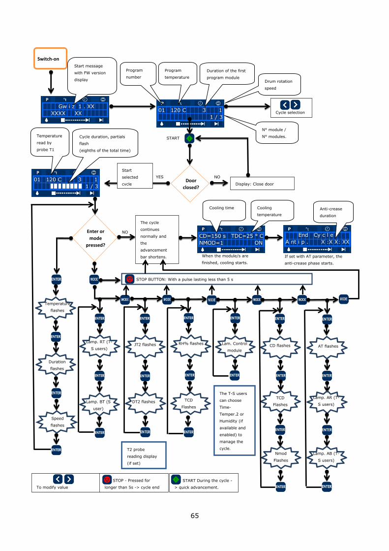
65
Gw i z 1 . XX
XXXX XX
Switch-on
01 120 C 3 1
1 / 3
Start message
with FW version
display
Program
number
Program
temperature
Duration of the first
program module
Drum rotation
speed
N° module /
N° modules.
Cycle selection
Door
closed?
NO
Display: Close door
YES
Start
selected
cycle
Enter or
mode
pressed?
NO
The cycle
continues
normally and
the
advancement
bar shortens.
Temperature
flashes
To modify value
Duration
flashes
Speed
flashes
Lamp. RT (T-
S users)
Lamp. BT (S
user)
JT2 flashes RH% flashes Lam. Control
module
01 120 C 3 1
1 / 3
Cycle duration, partials
flash
(eighths of the total time)
Temperature
read by
probe T1
CD flashes
DT2 flashes
T2 probe
reading display
(if set)
TCD
Flashes
The T-S users
can choose
Time-
Temper.2 or
Humidity (if
available and
enabled) to
manage the
cycle.
TCD
Flashes
Nmod
Flashes
AT flashes
Lamp. AR (T-
S users)
Lamp. AB (T-
S users)
End Cy c l e
A nt i p . X :X X: XX CD=150 s TDC=25 ° C
NMOD=1 ON
When the module/s are
finished, cooling starts.
If set with AT parameter, the
anti-crease phase starts.
Cooling time
Cooling
temperature
Anti-crease
duration
STOP BUTTON: With a pulse lasting less than 5 s
STOP - Pressed for
longer than 5s -> cycle end
START During the cycle -
> quick advancement.
START

66
6.9.1.1 Cycle programming limit.
10 programmable drying cycles are available for common use.
Only the first 5 are enabled in self-service configuration. During the cycle, the advancement bar is not refreshed if module durations are modified in the
meantime.
Attention! If power is missing during the MACHINE PARAMETER or CYCLE
modifications, the data is not stored and the procedure must be repeated from the beginning.
6.9.2 Technical user level (T) enabling procedure
The following parameter modification procedure is reserved for users with the technician qualification or who will have anyhow received proper training.
The operations described must be carried out with the machine not running.
Press < and ENTER simultaneously and type the password (5 times ENTER). When the letter “T” appears, the values of the cycles can be modified according to that shown in
paragraph “6.9.1 Programming the cycles”. Pressing <> simultaneously grants access to the parameter menu. To exit “T” mode, switch the appliance off and back on.
6.9.3 Tips for drying delicate garments
When drying particularly delicate garments (e.g. Silk, Wool, garments that require WET
CLEANING and can be dried on rotary dryers) and the speed regulation option is available, set a speed value that allows the laundry to be attached to the drum without falling. This reduces
the pilling and felting effects. In the same cases, increase the rotation time by at least 60 seconds and keep low drying temperatures, compatibly with the recommendations of the
supplier of the fabric.
01 120 C 3 1
1 / 3
Press > and ENTER
simultaneously.
X 5 P as swo r d
P as swo r d
*****
01 120 C 30 T 1
1 / 3
Press Enter five
times
The display of the letter ”T” confirms
enabling.
"MACHINE
PARAMETERS" menu
"CYCLES" menu
Enter or
<>
pressed
The additional values
indicated in the table
in paragraph 6.9.1
can be modified

67
6.9.4 Machine parameters menu
6.9.4.1 Table 1: parameters –values – enabled users
Parameter Options Default
Value
Min
value
Max
value
Enabled
user
“T” “S”
1 ki 38 0 100 X
2 kd 4 0 100 X
3 Kp 90 0 100 X
4 Band 20 0 100 X
5 Temperature °C - °F °C X X
6 EURO/$...01 (*) 1.00 0.10 599.90 X X
7 EURO/$...02 (*) 1.00 0.10 599.90 X X
8 EURO/$...03 (*) 1.00 0.10 599.90 X X
9 EURO/$...04 (*) 1.00 0.10 599.90 X X
10 EURO/$...05 (*) 1.00 0.10 599.90 X X
11 EURO/$...06 (*) 1.00 0.10 599.90 X X
12 EURO/$...07 (*) 1.00 0.10 599.90 X X
13 EURO/$...08 (*) 1.00 0.10 599.90 X X
14 EURO/$...09 (*) 1.00 0.10 599.90 X X
15 EURO/$...10 (*) 1.00 0.10 599.90 X X
16 Sys-Pay Exe-Imp-Par Exe X X
17 V-imp (*) 1.00 0.10 99.90 X X
18 CH 0 (*) 0.05 0.01 99.90 X X
19 CH 1 (*) 0.10 0.01 99.90 X X
20 CH 2 (*) 0.20 0.01 99.90 X X
21 CH 3 (*) 0.50 0.01 99.90 X X
22 CH 4 (*) 1.00 0.01 99.90 X X
23 CH 5 (*) 2.00 0.01 99.90 X X
24 TC 60s= (*) 0.10 0.10 599.90 X X
25 Par.M 1-10-100-1000 100 X
26 Heat Type Electric-Gas/Steam Electric X
27 Basket driving Type 0-1-2 Type 1 X
28 T2 On – Off Off X
29 RH% On - Off Off X
30 T mod min (min) 1 1 999 X
31 T mod max (min) 50 1 999 X
32 Bt min (s) 2 1 600 X
33 Bt max (s) 10 10 600 X
34 Rt min (s) 20 10 999 X X
35 Rt max (s) 300 60 999 X X
36 Buzzer On - Off On X X
37 Alarm filter 400 100 500 X
38
Cycles Par. -display-
Tot -display-
39 Tot. Pay -display-
40 Ex-C C - I C X X
41 Cycle timeout 60 10 90 X
42 Password Lev 1 Ins. Psw 1 Enter x5 X X
43 Password Lev 2 Ins. Psw 2 ***** X X
(*) The ranges depend on the parameter value “Par.M” as explained in the following diagram.
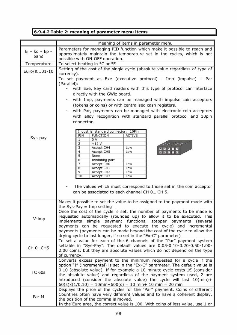
68
6.9.4.2 Table 2: meaning of parameter menu items
Meaning of items in parameter menu
ki – kd – kp -
band
Parameters for managing PID function which make it possible to reach and approximately maintain the temperature set in the cycles, which is not
possible with ON-OFF operation.
Temperature To select heating in °C or °F
Euro/$...01-10 Setting of the cost of the single cycle (absolute value regardless of type of currency).
Sys-pay
To set payment as Exe (executive protocol) - Imp (impulse) – Par
(Parallel): - with Exe, key card readers with this type of protocol can interface
directly with the GWiz board.
- with Imp, payments can be managed with impulse coin acceptors
(tokens or coins) or with centralised cash registers.
- with Par, payments can be managed with electronic coin acceptors
with alloy recognition with standard parallel protocol and 10pin
connector.
Industrial standard connector: 10Pin
PIN FUNCTION ACTIVE
1 0 V
2 +12 V
3 Accept CH4 Low
4 Accept CH5 Low
5 None
6 Inhibiting port
7 Accept CH0 Low
8 Accept CH1 Low
9 Accept CH2 Low
10 Accept CH3 Low
- The values which must correspond to those set in the coin acceptor
can be associated to each channel CH 0… CH 5.
V-imp
Makes it possible to set the value to be assigned to the payment made with
the Sys-Pay = Imp setting Once the cost of the cycle is set, the number of payments to be made is
requested automatically (rounded up) to allow it to be executed. This implements simple payment functions, stepper payments (several
payments can be requested to execute the cycle) and incremental
payments (payments can be made beyond the cost of the cycle to allow the drying cycle to last longer, if so set in the “Ex-C” parameter)
CH 0…CH5
To set a value for each of the 6 channels of the “Par” payment system
settable in “Sys-Pay”. The default values are 0.05-0.10-0.20-0.50-1.00-2.00 coins, but they are absolute values which do not depend on the type
of currency.
TC 60s
Converts excess payment to the minimum requested for a cycle if the option “I” (incremental) is set in the “Ex-C” parameter. The default value is
0.10 (absolute value). If for example a 10-minute cycle costs 1€ (consider the absolute value) and regardless of the payment system used, 2 are
introduced (consider the absolute value) the cycle will last 10(min)+ 60(s)x(1/0.10) = 10min+600(s) = 10 min+ 10 min = 20 min
Par.M
Displays the price of the cycles for the “Par” payment. Coins of different
Countries often have very different values and to have a coherent display, the position of the comma is moved.
In the Euro area, the correct value is 100. With coins of less value, use 1 or

69
10. With coins of a higher value, use 1000. If for example cycle 1 costs 1
(€) with Par.M=100, with Par.M= 1 the cost is displayed as 100, with Par.M=10 as 10.0 and with Par.M=1000 as 0.100 . All values relative to
costs are modified automatically.
Heat Type
Electric or gas/steam heating management can be chosen. In the first case, the PID is active while in the second the temperature band for ON-OFF
activation of the steam solenoid valve or of the two gas solenoid stages is managed.
Basket Driving
The type of movement management of the appliance's drum is defined.
Type 0 = without inversion Type 1 = with inversion
Type 2 = with speed variator
T2 Activates (ON) or deactivates (OFF) the optional temperature probe at the drain.
RH% Activates (ON) or deactivates (OFF) the optional relative humidity probe at
the drain.
Tmod min/max Allows you to set the minimum and maximum time limits of the modules.
Bt min/max Allows you to set the minimum and maximum time limits of the pause
between two left/right movements.
Rt min/max Allows you to set the minimum and maximum time limits of rotation
between two pauses.
Buzzer Activates the buzzer of the Gwiz board every time a button is pressed or signalling the end of the cycle.
Alarm filter Allows you to set a number of cycles after which the fluff filter must be
cleaned. If exceeded, “alarm filter” is displayed, which can be reset by opening the filter door for at least 5s.
Cycles Par/tot Displays the cycles carried out. When the reset, they are not zeroed.
Tot. Pay Displays the n° payments made in “Imp” mode. The value is zeroed when
reset.
EX-C Manages payment which exceeds the cost of the cycle. With the “C” option, excess credit is maintained for the subsequent cycle (if credit zeroing is not
enabled with the dip-switch 2 on the Gwiz board set at ON). The “I” option enables incremental payment which, according to that explained in “TC
60s”, overpayment is transformed into drying minutes. Remember that the duration of the cycle cannot exceed that set in the "timeout" parameter
described below.
Cycle timeout Limits operation of the appliance and avoids fire hazards due to excessive drying of the laundry.
Password 1 Allows the “T” technician user to modify the password
Password 2 Allows the manufacturer's “S” technician user to modify the password.
6.9.4.3 Navigation in parameters menu
To enter the parameters menu, proceed as indicated in 6.9.2. When the letter “T” appears, press the plus or minus arrows (<>) simultaneously to display the first parameter. Pressing
MODE several times in the parameters menu displays all the available parameters. Once all the
parameters have been displayed, pressing MODE again repeats the list in cyclical mode. Pressing <> changes the available values/options.
Press ENTER once to display the first parameter on the list. Pressing it again displays the cycles.
To go back to the “common user” level, switch the appliance off and back on.

70
6.9.5 Checking status of digital inputs and DIP SWITCHES
The Gwiz logic board has 4 digital inputs in the form of DIP SWITCHES. (The functions are displayed in the tables in this paragraph).
The appliance electronics allow you to check the status of the digital inputs. To access the function, just set dip switch 4 on the control board at OFF. This operation allows you to view:
The analogue value read by the board and relative conversion in °C detected by the
temperature probes. The status of the digital inputs detected by the control board
To change position of the dip switch, remove the upper panel (refer to figures 40, 41, and 42)
01 120 C 30 T 1
1 / 3
P a r. K i
3 8
Enable “T” user level as indicated in 6.9.2 Pressing <> displays the first
parameter of the list indicated in
the table 6.9.4.1
P a r. Kd
4
Pressing MODE displays in succession
all the parameters of the tables
6.9.4.1 explained in table 6.9.4.2.
Figure 40
Removal of the upper panel
Figure 41 Control board position
Figure 42 Dip switch position in the electronic control board for appliance configuration
Remove the 2 upper
fixing screws
Continue the same way for all the parameters. Pressing ENTER allows you to go back to the first
parameter on the list. Pressing ENTER again goes back to displaying the cycles.
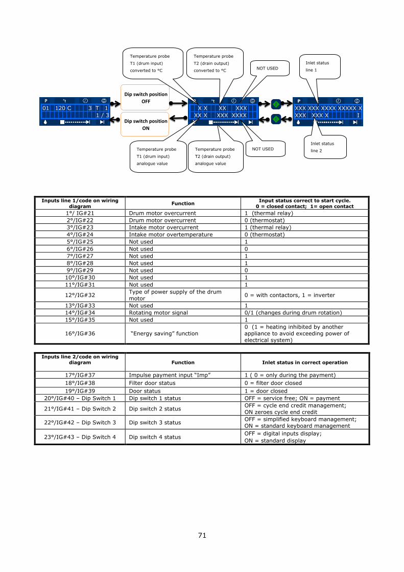
71
Inputs line 1/code on wiring diagram
Function Input status correct to start cycle.
0 = closed contact; 1= open contact
1°/ IG#21 Drum motor overcurrent 1 (thermal relay)
2°/IG#22 Drum motor overcurrent 0 (thermostat)
3°/IG#23 Intake motor overcurrent 1 (thermal relay)
4°/IG#24 Intake motor overtemperature 0 (thermostat)
5°/IG#25 Not used 1
6°/IG#26 Not used 0
7°/IG#27 Not used 1
8°/IG#28 Not used 1
9°/IG#29 Not used 0
10°/IG#30 Not used 1
11°/IG#31 Not used 1
12°/IG#32 Type of power supply of the drum
motor 0 = with contactors, 1 = inverter
13°/IG#33 Not used 1
14°/IG#34 Rotating motor signal 0/1 (changes during drum rotation)
15°/IG#35 Not used 1
16°/IG#36 “Energy saving” function
0 (1 = heating inhibited by another
appliance to avoid exceeding power of
electrical system)
Inputs line 2/code on wiring diagram
Function Inlet status in correct operation
17°/IG#37 Impulse payment input “Imp” 1 ( 0 = only during the payment)
18°/IG#38 Filter door status 0 = filter door closed
19°/IG#39 Door status 1 = door closed
20°/IG#40 – Dip Switch 1 Dip switch 1 status OFF = service free; ON = payment
21°/IG#41 – Dip Switch 2 Dip switch 2 status OFF = cycle end credit management;
ON zeroes cycle end credit
22°/IG#42 – Dip Switch 3 Dip switch 3 status OFF = simplified keyboard management;
ON = standard keyboard management
23°/IG#43 – Dip Switch 4 Dip switch 4 status OFF = digital inputs display;
ON = standard display
Dip switch position
OFF
01 120 C 3 T 1
1 / 3
X X XX XXX
XX X XXX XXXX
XXX XXX XXXX XXXXX X
XXX XXX X I
XX X XXX XXX Dip switch position
ON
Temperature probe
T1 (drum input)
converted to °C
Temperature probe
T2 (drain output)
converted to °C NOT USED
Temperature probe
T1 (drum input)
analogue value
Temperature probe
T2 (drain output)
analogue value
NOT USED
Inlet status
line 1
Inlet status
line 2

72
6.10 Loading "default parameters" (reset operation)
Attention!
The reset procedure must be performed by qualified personnel
and strictly following the instructions provided. Eliminates all modifications and any special programs.
Restores default parameters and programs and disables temperature and humidity probes (optional). They cannot be
restored without intervention of a trained/qualified technician as they require password and specific procedures.
If the data reset procedure is performed incorrectly it can be
repeated without damaging the circuit board. It does not cancel the n° of drying cycles carried out.
Flow chart of reset operation.
6.11 Restoring default parameters of inverter and modifying speed settings
On these appliances, the inverter parameters are set manually.
Attention!
The operation is intended for qualified technicians alone.
The inverter must be programmed when it is replaced or when modifying the preset speed
settings (from 1 to 7). Due to the type of operations, they are described in the maintenance chapter.
Switch-on
The start message appears with the
installed FW version displayed. Always
keep “<” and “>” pressed.
Gw i z 1 . XX
XXXX XX
R es e t
The word “Reset” appears but
does NOT flash. Keep “<” and “>”
pressed.
Switch the machine on and keep
both keys “<” and “>” pressed
until the end of the procedure!
R es e t
The word "Reset" flashes, keys “<” and “>” can
be released. The procedure is complete. Switch
off the machine to exit from this status.
Deactivation

73
6.12 Power cut during operation
In the event of power cut during the execution of a program, the appliance stops safely until
power supply is restored.
Attention!
The temperature inside the drum will rise for the first minutes following the power cut.
6.13 Deletion of an alarm
During execution of a cycle or when pressing the start button, messages can appear such as “close door” or “door filter close”. These are reset by closing the door or filter door. The
message “Pause” appears. Press START to start the cycle or to resume normal operation. When messages appear consisting of "Alarm" followed by an error code, they can only be reset
by switching the appliance off and back on.
Attention! The alarms generated by motor and inverter management require
a long time to reset. Wait at least 5 minutes before re-starting the appliance.
When 5 minutes have elapsed, power the appliance once again.
To resolve the problems indicated by the error code, see the specific paragraph in chapter 7.

74
7 SAFETY FUNCTIONS AND DEVICES
Attention! The appliance is supplied with the safety devices listed below.
Protective fuses for the power line and for the individual components.
Door closed detection micro switch. Emergency stop. It allows you to stop the cycle in progress in case of emergency (borne
by the distributor of the self versions). Negative pressure sensor in the air circuit, which fails to enable heating in the presence
of poor negative pressure. Automatic and manual rearmed safety thermostats. These control the air temperature in
the circuit in many points of the appliance.
Thermal relay(s) and internal thermostat(s) of the motor(s). Drum and intake motor inverter (optional) with safety inputs capable of disconnecting
power outputs. The inverter also adjusts the motor speed, checks and protects the controlled motor and itself from malfunctions, such as: excessive temperature of the
circuits or heat sinks, overcurrent, short-circuit, etc.). Over-load sensor (with inverter option). This is an electronic system that can determine
whether the drum has been overloaded with laundry by an excessive number of kg. Flame presence sensor: available only in models with gas heating.
Drum rotation sensor
REED-type closed filter door sensor which avoids possible malfunctioning due to the humid and dusty environment in which it is inserted and guarantees a high number of
operations.
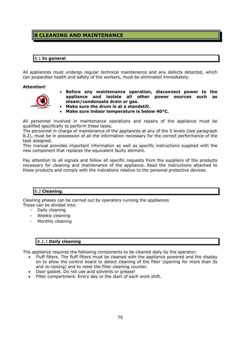
75
8 CLEANING AND MAINTENANCE
8.1 In general
All appliances must undergo regular technical maintenance and any defects detected, which
can jeopardise health and safety of the workers, must be eliminated immediately.
Attention! Before any maintenance operation, disconnect power to the
appliance and isolate all other power sources such as
steam/condensate drain or gas. Make sure the drum is at a standstill.
Make sure indoor temperature is below 40°C.
All personnel involved in maintenance operations and repairs of the appliance must be qualified specifically to perform these tasks.
The personnel in charge of maintenance of the appliances at any of the 5 levels (see paragraph 8.2), must be in possession of all the information necessary for the correct performance of the
task assigned.
This manual provides important information as well as specific instructions supplied with the new component that replaces the equivalent faulty element.
Pay attention to all signals and follow all specific requests from the suppliers of the products
necessary for cleaning and maintenance of the appliance. Read the instructions attached to these products and comply with the indications relative to the personal protective devices.
8.2 Cleaning.
Cleaning phases can be carried out by operators running the appliances These can be divided into:
- Daily cleaning
- Weekly cleaning
- Monthly cleaning
8.2.1 Daily cleaning
The appliance requires the following components to be cleaned daily by the operator;
Fluff filters. The fluff filters must be cleaned with the appliance powered and the display on to allow the control board to detect cleaning of the filter (opening for more than 5s
and re-closing) and to reset the filter cleaning counter. Door gasket. Do not use acid solvents or grease!
Filter compartment. Every day or the start of each work shift.

76
Figure 44 coil optional filter position with steam heating
8.2.2 Weekly cleaning.
For models with steam heating, clean the inlet filter on a weekly basis.
In this case, clean with: Machine off and cold
Steam and condensate gate valves closed.
Attention!
Clean the filter with the machine cold. Do not start the appliance without this device engaged.
Failure to clean the filter leads to rapid deterioration of appliance performance.
8.2.3 Monthly cleaning.
Clean the cover panels with a damp cloth. Do not use flammable or abrasive products.
Attention!
Always keep the cooling openings in the rear of the appliance free from dust.
Do not access with limbs or tools. Clean the display surface and control panels in general using a
slightly damp cloth. Solvents and/or abrasive substances
irreparably damage these surfaces. Do not exert too much pressure.
Never use direct jets of water to clean the appliance.
The formation of condensate on the display glass can irreparably damage the display. Even if the appliance is not to be started, any drops of water must be dried immediately.
Like all electronic components, the display is sensitive to electrostatic discharges. When use of the appliance has been concluded, switch it off, disconnect it from the power
supply sources and leave the door open.
Air filter for the steam coil.

77
8.2.4 Daily, weekly and monthly maintenance and cleaning register
An example on how a routine maintenance register can be structured is provided below. This
register must accompany the appliance.
Starting the appliance
OK KO Activity Date Signature Notes
Clean the filter and filter compartment at the drain.
Power the appliance with the power supply sources required.
Record any operation anomalies.
End of the day
OK KO Activity Date Signature Notes
Disconnect the electric power supply.
Disconnect any other power supply sources.
Clean the contact area of the door gasket.
Check drum is empty and clean.
Leave the door open.
Record any operation anomalies.
8.2.5 Releasing laundry and drum maintenance
Should the laundry get stuck inside the drum or if the drum requires adjustments to eliminate imperfections, proceed as follows:
Disconnect power and block the switch. Disconnect all types of energy sources (steam, gas) and close the shut-off devices.
Release the stuck laundry (probably at the loading inlet) and adjust the drum (for example abrasion due to treating laundry with hinges/metal accessories).
Turn the power sources back on and resume normal use.
This operation can be carried out by the appliance operators if
sufficiently trained to perform that described above. Otherwise request the intervention of a technician.
If the problem occurs frequently, request intervention of a technician to check centring of the drum.
8.3 Maintenance: types and warnings
Maintenance is divided into five different levels: Routine maintenance
It has the purpose of preserving the efficiency and safety of the appliance. Preventive maintenance
Intervene on the appliance in advance to prevent faults or malfunctions on the basis of
the manufacturer's experience. Corrective or necessary maintenance
Call-out intervention due to fault or sudden malfunction. Pro-active maintenance
Generally, adaptation for improving the protection rating of the appliance or adaptation to the amended Standards in force.
Extraordinary maintenance All important modernisation interventions aimed at prolonging the life span of the
appliance or its efficiency, without modifying the functional features and the structure of
the appliance.
78
The first three types of maintenance must be considered normal activities, which an appliance
may and should undergo.
In the last two types of maintenance instead, significant variations can be made to appliance functionality. Repercussions occur at a Standards and legislative level, which must be taken
into consideration.
Attention!
Any maintenance must be performed by authorised after-sales centres or by duly trained personnel.
All maintenance interventions not included in this manual exclude all liability of the manufacturer, who considers itself foreign to any possible repercussions of legal nature.
Attention!
Aside from that described in paragraph 8.1, pay attention to the
following points:
Even if the disconnecting switch on the machine is off, the
input terminals could be powered! In the event of interventions on the motor or on the inverter
(speed regulator), wait 5 minutes from switch-off of the disconnector switch to allow residual voltage in the inverter to
discharge. Never disable the safety devices for any reason.
Only use original spare parts and if in doubt, consult our
technical department as soon as possible, stating the model and serial number that can be found on the plate positioned on
the rear of the appliance.
8.3.1 Routine maintenance: operation of safety systems and cleaning. Cleaning
frequency.
Check the following daily:
Check that the drying cycle does not start with the door open and that drum rotation stops if the door is opened during the drying cycle.
Check that the drying cycle does not start with the filter inspection panel open and that drum rotation stops with drying cycle in progress if the panel is opened.
Check that the steam supply filter is clean (in appliances with this type of heating and with steam coil filter option).
Clean/remove all traces of dust accumulated inside and/or outside of the appliance.

79
Attention! Dust can be source of fire.
Write down the maintenance operation and the number of cycles indicated in the parameters
menu.
8.3.2 Routine maintenance: lubrication of bearings. Every three months.
Lithium-based lubricant grease must be introduced into the 2 greasing points positioned on the
two bearing-supports along with additives for high temperatures (NLGI 2) (see figure 45). To access the bearings, remove the top rear panel of the appliance using a Torx TX30
screwdriver. There could be a gearmotor depending on the type of drive used for the drum.
Attention! The grease is only used to lubricate the front and rear bearings.
Excessive lubrication can be just as damaging as poor lubrication. Never use petrol-based lubricants with silicone-based lubricants.
Re-assemble the upper rear panel, which was previously removed
in order to reach the bearing supports.
The grease introduced cannot reach areas of the appliance where the laundry is normally loaded.
If the type of grease used is different from that indicated, check that the 2 types of grease are compatible. Lithium-based lubricants are compatible with calcium-based lubricants but not with
sodium-based lubricants.
Write down the maintenance operation and the number of cycles indicated in the parameters
menu.
Figure 52 Bearing greasing position.
Tighten the shaft fixing screws in the front and rear bearings.

80
8.3.3 Routine maintenance: check the state and adjustment of the belts. Every
6 months.
These appliances, except for the version with gearmotor, can have 1 or 2 transmission belts.
The first (belt 1 – fig. 46) transmits motion between the transmission shaft and the pulley joined to the drum. It is Poly-V-type and is found inside the tank. The second (belt 2 – fig. 46)
transmits motion between the motor pulley and the transmission pulley. It is at the bottom of rear part of the appliance (easy to reach) and is the V-type belt.
To service the transmission belts, remove the bottom rear panel using a torx TX30 screwdriver and then (referring to figure 46):
Loosen the screw “D” and turn the inspection cap “E” . Block it so that belt 1 remains visible.
Check that belt 1 is not excessively worn or faulty. If it needs to be replaced, contact the technical service as specific instructions are required.
Check that belt 2 is not excessively worn or faulty. Request the original spare part if it
needs to be replaced. Check that belt 1 is well tensioned. If not, proceed as follows:
o Loosen the screws “A2” a half-turn - Turn the 13mm socket wrench
anticlockwise (they only need to be loosened and not removed).
o Loosen the lock nut “B2” - Turn the 13mm fixed spanner anticlockwise.
o Turn the screw “C2” clockwise with a 13mm fixed spanner until tension is
correct.
o Tighten the nut “B2”.
o Tighten the screws “A2”.
o Check that belt tension is correct. If not, repeat the operations shown above.
Check that belt 2 is tensioned correctly. (PLEASE NOTE: when the tension of belt 1 is adjusted, belt 2 must be checked as well.) Then proceed as follows:
o Loosen the screws “A1” a half-turn - Turn the 13mm socket wrench
anticlockwise (they only need to be loosened and not removed).
o Loosen the lock nut “B1” - Turn the 13mm fixed spanner anticlockwise.
o Turn the screw “C1” clockwise with a 13 mm fixed spanner until tension is
correct.
o Tighten the nut “B1”.
o Tighten the screws “A1”.
o Check that belt tension is correct. If not, repeat the operations shown above.
Check that belt 2 is parallel to the rear panel. To do so, use the back of the side panels
as a reference, for example sliding a straight metal bar. If needed, re-align the pulleys “P1” and “P2”.
When the prior controls are finished. start a full load cycle and make sure the belts do not slip.
Refit the inspection cap “E” secure it with the relative screw “D”
Reposition the lower rear panel.
Write down the maintenance operation and the number of cycles indicated in the parameters menu.
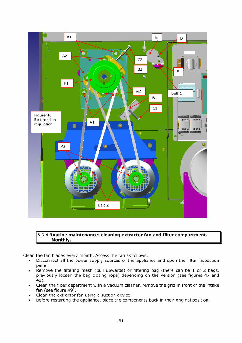
81
8.3.4 Routine maintenance: cleaning extractor fan and filter compartment.
Monthly.
Clean the fan blades every month. Access the fan as follows:
Disconnect all the power supply sources of the appliance and open the filter inspection panel.
Remove the filtering mesh (pull upwards) or filtering bag (there can be 1 or 2 bags,
previously loosen the bag closing rope) depending on the version (see figures 47 and 48).
Clean the filter department with a vacuum cleaner, remove the grid in front of the intake fan (see figure 49).
Clean the extractor fan using a suction device. Before restarting the appliance, place the components back in their original position.
Figure 46 Belt tension regulation
A1
B2
C2
D E
F
A2
A1
A2
C1
B1
P1
P2
Belt 2
Belt 1

82
Filtering mesh, pull upwards
Extraction direction of the filtering mesh
Grid to be removed to
access the extractor fan
Filtering bags (one or two, depending on the version)
Loosen the tightening rope of the bags before removing them
Figure 47 position of the version with filtering mesh
Figure 48 position of the version with filter bags
Figure 49 position of the fan grid
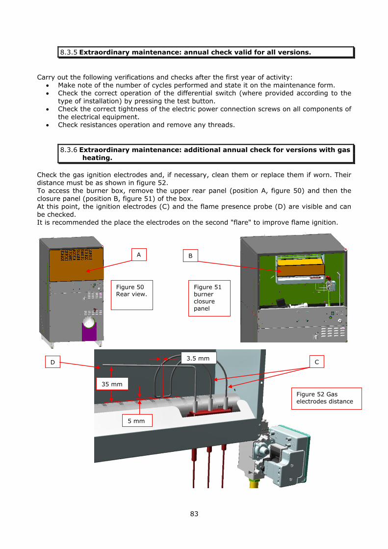
83
8.3.5 Extraordinary maintenance: annual check valid for all versions.
Carry out the following verifications and checks after the first year of activity:
Make note of the number of cycles performed and state it on the maintenance form. Check the correct operation of the differential switch (where provided according to the
type of installation) by pressing the test button. Check the correct tightness of the electric power connection screws on all components of
the electrical equipment. Check resistances operation and remove any threads.
8.3.6 Extraordinary maintenance: additional annual check for versions with gas
heating.
Check the gas ignition electrodes and, if necessary, clean them or replace them if worn. Their
distance must be as shown in figure 52. To access the burner box, remove the upper rear panel (position A, figure 50) and then the
closure panel (position B, figure 51) of the box. At this point, the ignition electrodes (C) and the flame presence probe (D) are visible and can
be checked. It is recommended the place the electrodes on the second "flare" to improve flame ignition.
A B
C D 3.5 mm
5 mm
35 mm
Figure 50 Rear view.
Figure 51 burner closure panel
Figure 52 Gas electrodes distance
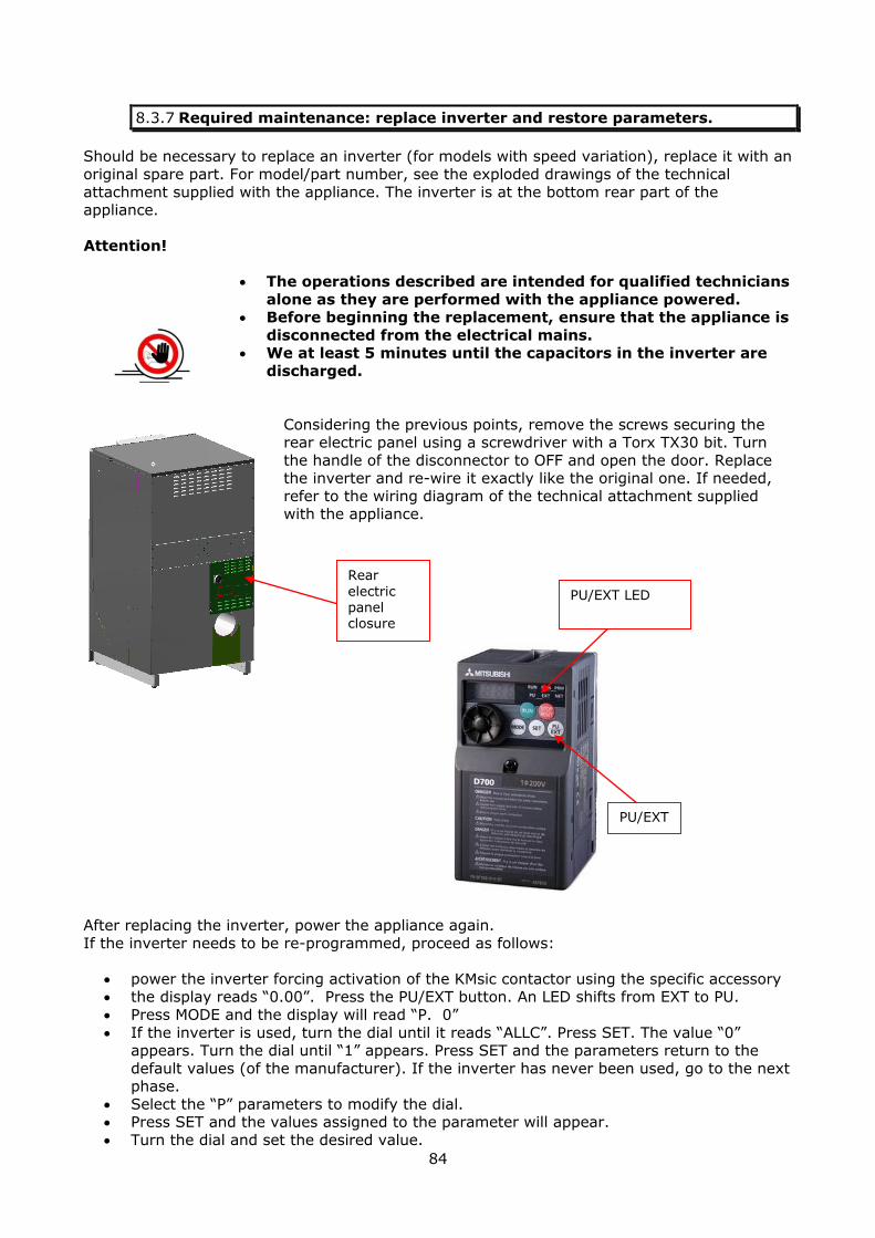
84
8.3.7 Required maintenance: replace inverter and restore parameters.
Should be necessary to replace an inverter (for models with speed variation), replace it with an
original spare part. For model/part number, see the exploded drawings of the technical
attachment supplied with the appliance. The inverter is at the bottom rear part of the appliance.
Attention!
The operations described are intended for qualified technicians
alone as they are performed with the appliance powered. Before beginning the replacement, ensure that the appliance is
disconnected from the electrical mains. We at least 5 minutes until the capacitors in the inverter are
discharged.
Considering the previous points, remove the screws securing the rear electric panel using a screwdriver with a Torx TX30 bit. Turn
the handle of the disconnector to OFF and open the door. Replace the inverter and re-wire it exactly like the original one. If needed,
refer to the wiring diagram of the technical attachment supplied with the appliance.
After replacing the inverter, power the appliance again.
If the inverter needs to be re-programmed, proceed as follows:
power the inverter forcing activation of the KMsic contactor using the specific accessory the display reads “0.00”. Press the PU/EXT button. An LED shifts from EXT to PU.
Press MODE and the display will read “P. 0”
If the inverter is used, turn the dial until it reads “ALLC”. Press SET. The value “0” appears. Turn the dial until “1” appears. Press SET and the parameters return to the
default values (of the manufacturer). If the inverter has never been used, go to the next phase.
Select the “P” parameters to modify the dial. Press SET and the values assigned to the parameter will appear.
Turn the dial and set the desired value.
Rear
electric panel closure
PU/EXT
PU/EXT LED

85
Press SET. The new value will flash. Press SET again to confirm it and to go to the next parameter.
Select the next parameter and modify it.
Having modified all the parameters, press MODE twice The display reads “0.00”. Remove the accessory used for the forced activation of the KMsic contactor.
The inverter is now programmed and ready for use. The following is a list of parameters to set depending on the size of the appliance.
Parameters 4-5-6 and 24-25-26-27 determine respectively the
rotation speed of the drum from 1 to 7 settable in the cycles. If the preset values do not meet customer requirements, they
can be modified but must never exceed 80. The appliance could undergo fast deterioration.
Modello GDZ11/14 GDZ 18/24
Parametro valore
1 80 80 frequenza max
4 44 30 velocità 1
5 46 38 velocità 2
6 48 42 velocità 3
7 4 4 accelerazione
8 2 2 decelerazione
9 2,1 2,4 termica motore (0,37 kW)
24 50 44 velocità 4
25 54 46 velocità 5
26 58 58 velocità 6
27 65 62 velocità 7
67 2 2 numero reset errori
68 3 3 tempo tra i reset
71 3 3 tipo motore (standard)
72 12 12 frequenza PWM
80 0,37 0,55 potenza motore
83 230 230 tensione alimentazione
84 50 50 frequenza alimentazione
Parametri GDZ : inverter + cinghie
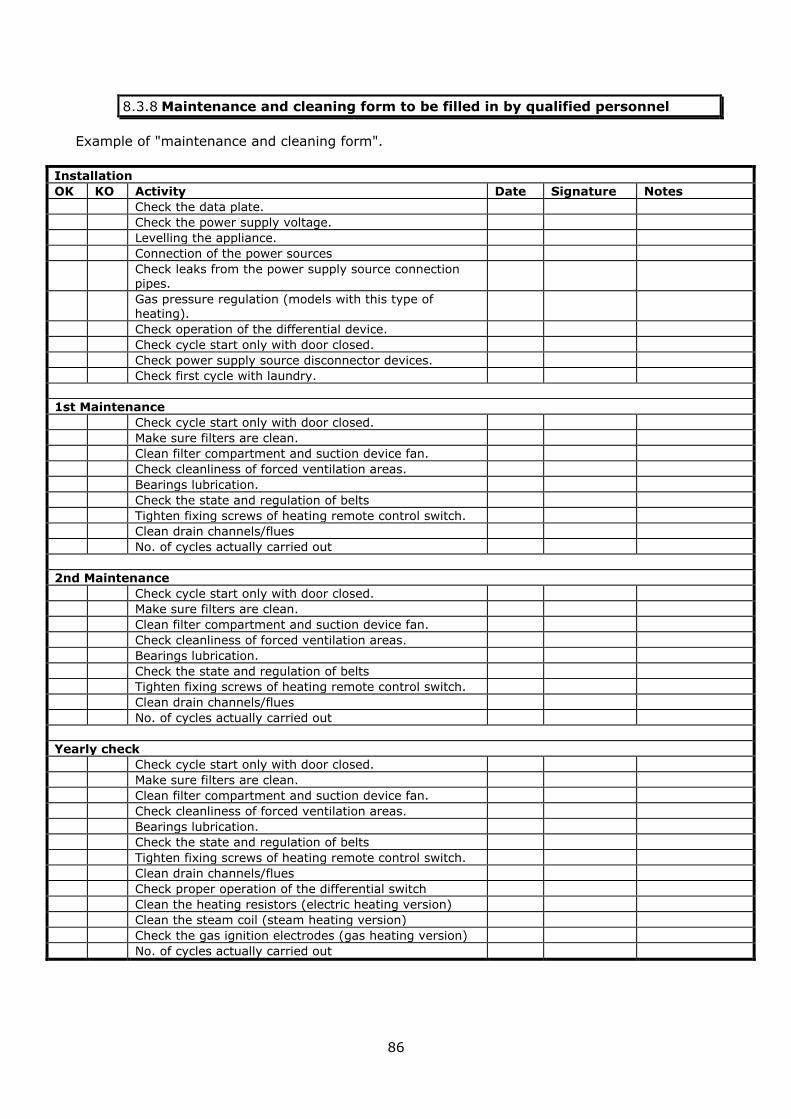
86
8.3.8 Maintenance and cleaning form to be filled in by qualified personnel
Example of "maintenance and cleaning form".
Installation
OK KO Activity Date Signature Notes
Check the data plate.
Check the power supply voltage.
Levelling the appliance.
Connection of the power sources
Check leaks from the power supply source connection pipes.
Gas pressure regulation (models with this type of heating).
Check operation of the differential device.
Check cycle start only with door closed.
Check power supply source disconnector devices.
Check first cycle with laundry.
1st Maintenance
Check cycle start only with door closed.
Make sure filters are clean.
Clean filter compartment and suction device fan.
Check cleanliness of forced ventilation areas.
Bearings lubrication.
Check the state and regulation of belts
Tighten fixing screws of heating remote control switch.
Clean drain channels/flues
No. of cycles actually carried out
2nd Maintenance
Check cycle start only with door closed.
Make sure filters are clean.
Clean filter compartment and suction device fan.
Check cleanliness of forced ventilation areas.
Bearings lubrication.
Check the state and regulation of belts
Tighten fixing screws of heating remote control switch.
Clean drain channels/flues
No. of cycles actually carried out
Yearly check
Check cycle start only with door closed.
Make sure filters are clean.
Clean filter compartment and suction device fan.
Check cleanliness of forced ventilation areas.
Bearings lubrication.
Check the state and regulation of belts
Tighten fixing screws of heating remote control switch.
Clean drain channels/flues
Check proper operation of the differential switch
Clean the heating resistors (electric heating version)
Clean the steam coil (steam heating version)
Check the gas ignition electrodes (gas heating version)
No. of cycles actually carried out
87
9 TROUBLESHOOTING
In case of faults, the appliance signals them by displaying the "Alarm" message followed by an identification code. All details are described in the following paragraphs "ALARMS
DESCRIPTION" and "DISPLAY MESSAGES".
Attention!
If an unavailable component is to be replaced, padlock the disconnector switch in the off position.
Place a sign on the appliance stating “APPLIANCE OUT OF SERVICE, DO NOT USE” and re-position all previously removed
panels.
9.1 Description of alarms, possible causes and solutions.
The view of any alarm on the display is always active.
In the event of anomalies that can jeopardise the safety of the operator or the integrity of the appliance components, all activities that the appliance was performing will be stopped on
immediate activation of the buzzer (even though deactivated in the parameters menu). When displaying the alarm, the buzzer activates. To stop the buzzer, press STOP.
ALARM 01 DRUM MOTOR: OVERCURRENT (C) OR OVERTEMPERATURE (T)
CAUSE If the letter “C” is coupled to code 01, a motor overcurrent or short-circuit is
signalled. If the letter “T” is coupled to code 01, motor overtemperature is signalled.
ALARM RESET
Reset the alarm (C) by switching the appliance off and back on and by pressing the
reset button on the thermal relay of the motor. Reset the alarm (T) by switching the appliance off and back on, after having waited approximately 30 minutes for the motor to cool off and for the thermistor inside to reactivate.
WHAT TO CHECK Amount of laundry loaded in the drum Presence of the three power supply phases in the three-phase version.
Check the motor power supply cable and the correct operation of the remote control.
CORRECTIVE ACTION
Cleaning and checking the motor cooling fan. Check the drum bearings, lubricate or replace them, if required.
88
ALARM 02 INTAKE MOTOR: OVERCURRENT (C) OR OVERTEMPERATURE (T)
CAUSE If the letter “C” is coupled to code 02, a motor overcurrent or short-circuit is signalled. If the letter “T” is coupled to code 02, motor overtemperature is signalled.
ALARM RESET
Reset the alarm (C) by switching the appliance off and back on and by pressing the
reset button on the thermal relay of the motor. Reset the alarm (T) by switching the appliance off and back on, after having waited approximately 30 minutes for the
motor to cool off and for the thermistor inside to reactivate.
WHAT TO CHECK
Cooling fan of the extraction motor and fan Amount of laundry loaded in the drum
Presence of the three power supply phases in the three-phase version. Check the motor-fan power supply cable and the correct operation of the remote control.
CORRECTIVE ACTION
Cleaning and checking the motor cooling fan. Clean and check the fan impeller: the system must run easily when in manual mode.
Check the drum bearings, lubricate or replace them, if required
ALARM 03 FUNCTION NOT ENABLED: WIRING ERROR
CAUSE As the function is not enabled, it is a wiring error.
ALARM RESET Check wiring and after adjusting it, switch the appliance off and back on
WHAT TO CHECK Correctness of the digital input values.
CORRECTIVE ACTION
Adjust wiring
ALARM 04 INCOMPATIBILITY OF OPEN/CLOSED DOOR SIGNALS WITH STATUS OF
INVERTER POWER SUPPLY CONTACTOR
CAUSE The door microswitch and the signal of the inverter power supply relay are not compatible. For example door open and contactor active.
ALARM RESET The alarm is removed upon reset of the contact operation and upon reactivation of the appliance.
WHAT TO CHECK Correct operation of the microswitch inside the hinge. Correct wiring of power contactor of inverter. Activation of contactor when cycle starts. Correct setting of “Basket driving” parameter in parameters menu.
CORRECTIVE ACTION
Replace door hinge. Replace inverter power contactor.
ALARM 05 INVERTER SAFETY CONTACTOR FAULTY
CAUSE The inverter power supply contactor (in the version with this option) is detected closed with cycle not in progress.
ALARM RESET The alarm is removed only by switching the appliance off and on and by replacing the
faulty component.
WHAT TO CHECK The normally open contact that powers the inverter (KMSIC) must be opened when
the appliance is not running a cycle and closed when the appliance is running a cycle.
CORRECTIVE
ACTION Replacement of the faulty contactor

89
ALARM 06 INLET TEMPERATURE PROBE (T1) FAULTY
CAUSE If temperature probe T1 is not connected or if a temperature higher than 170°C is detected, all functions are disabled and any cycle in progress is aborted.
ALARM RESET The alarm is removed by switching the machine off and on again.
WHAT TO CHECK
Integrity of the temperature probe: cable + sensitive element + connector.
Measure the resistance between the 2 terminals of the probe connector (disconnected
from the board). Correct connection of the wiring onto the electronic board. Correct heating operation.
CORRECTIVE ACTION
Replacement of the temperature probe if failed. Restore the electric connection on the electronic board.
Replace the faulty heating component with a new one.
ALARM 07 OUTLET TEMPERATURE PROBE (T2) FAULTY
CAUSE If temperature probe T2 is not connected or if a temperature higher than 85°C is detected, all functions are disabled and any cycle in progress is aborted.
ALARM RESET The alarm is removed by switching the machine off and on again.
WHAT TO CHECK
Integrity of the temperature probe: cable + sensitive element + connector.
Measure the resistance between the 2 terminals of the probe connector (disconnected from the board). Correct connection of the wiring onto the electronic board.
Correct heating operation.
CORRECTIVE ACTION
Replacement of the temperature probe if failed.
Restore the electric connection on the electronic board. Replace the faulty heating component with a new one.
ALARM 08 TEMPERATURE PROBE ANOMALY
CAUSE In the event the inlet temperature probe (T1) reads a lower temperature compared to that measured at the outlet (T2) for a time greater than 4 minutes, the cycle is
aborted.
ALARM RESET The alarm is removed only by switching the machine off and on again.
WHAT TO CHECK Heating components and temperature probes Connection of the temperature probes.
Probe connection inversion
CORRECTIVE ACTION
Replace the faulty heating component or temperature probe. Check the connection cable, the sensitive element and the temperature probe connector.
ALARM 09 CYCLE TEMPERATURE ANOMALY
CAUSE
During the cycle (not during the pause) if the temperature detected at inlet exceeds that set by 30°C for longer than 90 seconds, the cycle is aborted. There could be high temperature differences, with a cycle of several modules, and there is not enough
time to return within the intended range.
ALARM RESET The alarm is removed only by switching the machine off and on again.
WHAT TO CHECK Heating remote control switch, coil and power contacts. TEMP1 temperature probe.
CORRECTIVE ACTION
Replace the faulty heating component
Check and/or replace the connection cable, the sensitive element and the TEMP1 probe connector. Check that the probe connector is connected correctly to the Gwiz
board.
90
ALARM 10 NO FLAME IGNITION: DEDUCED AND INDUCED.
CAUSE In gas heating versions, the inlet temperature trend during the heating phases is assessed. The alarm triggers if the trend is negative for a certain period of time. This
is a deduced alarm.
ALARM RESET
The signal must be considered steady and can be eliminated only by removing and
re-applying voltage to the machine. The flame control device, which commands opening of the gas valve, carries out its own procedure. If the flame does not light or is not detected as such, after 3 ignition
attempts, the fault is signalled by switching on of the green button at the back of the appliance. This error signal is induced. Press the button to reset.
WHAT TO CHECK Check the correct position of the ignition electrodes and flame detection device. Check that the gas valve is open. If the appliance has remained idle for a long time, repeat the reset and the ignition several times to purge the gas supply pipe.
CORRECTIVE
ACTION
Position of the ignition electrodes and flame detection device.
Gas valve opening Press the gas alarm reset button
ALARM 11 (code not displayed)
OPEN DOOR: “CLOSE DOOR” signal
CAUSE The drum loading door has been opened during the execution of a cycle. A cycle has tried to be started with the door open.
Incorrect signal from hinge microswitches.
ALARM RESET The signal is removed as soon as the door is closed. If in cycle, “PAUSE” appears.
Press START to resume the cycle.
WHAT TO CHECK Check the correct closure of the door and operation of the door switches.
CORRECTIVE
ACTION Close the door or replace the door hinge with the incorporated micro switches.
ALARM 12
(code not displayed)
FILTER PANEL OPEN: “CLOSE DOOR FILTER” signal
CAUSE
Attempt to start a cycle with the filter door open. The filter door was opened during the cycle. The magnet placed on the filter door is faulty or missing.
The filter door microswitch is faulty or it is not aligned with the door magnet.
ALARM RESET The signal is removed as soon as the filter door is closed.
If in cycle, “PAUSE” appears. Press START to resume the cycle.
WHAT TO CHECK Check the alignment of the magnet and microswitch of the filter door. Check the operation of the micro-switch Check the presence of the magnet on the filter door.
CORRECTIVE ACTION
Close the filter door Check the presence of the magnet on the filter door.
Replace the micro switch of the filter door.

91
ALARM 13
(code not displayed)
FILTER CLEANING: ALARM FILTER signal
CAUSE
The filter door has not been opened for periodical cleaning of the fluff filter. This operation must be done with the machine powered. In this case the processor
microswitch detects opening of the filter door and deduces it has been cleaned.
Cleaning frequency depends on the value set in the parameters menu. It appears at the end of the cycle and does not allow others to be performed.
ALARM RESET Open and close the filter door for at least 5 seconds.
WHAT TO CHECK When the filter door opens the alarm “CLOSE DOOR FILTER” must appear.
Check the micro switch changeover of the filter door.
CORRECTIVE ACTION
Open and close the filter door with the appliance powered for no longer than 5 seconds. Replace the microswitch of the filter door if faulty.
ALARM 14 FUNCTION NOT ENABLED: WIRING ERROR
CAUSE As the function is not enabled, it is a wiring error.
ALARM RESET Check wiring and after adjusting it, switch the appliance off and back on
WHAT TO CHECK Correctness of the digital input values.
CORRECTIVE
ACTION Adjust wiring
ALARM 15 DRUM MOVEMENT ANOMALY
CAUSE During operation, the drum movement sensor changeover is not detected within 10 seconds.
ALARM RESET The signal is removed upon deactivation and reactivation of the appliance.
WHAT TO CHECK
Proper operation of the drum movement sensor.
Position of the magnet at the rear of the drum near the sensor. Distance between
sensor and magnet. Operation of the drum motor. State of the drum movement transmission belts: they must not slide. Operation of the contactor that powers the motor.
In the version with reducer, check that this is intact. In the version with inverter option: - check that this is powered and not in alarm
- check that the safety circuit is intact
CORRECTIVE ACTION
Replace the faulty component. Adjust the transmission belts.
Attention!
In order to remove alarm AL15 completely, if generated from the inverter (speed regulator), switch the appliance off for at least 5
minutes (time required for the inverter to switch off completely
and reset its internal alarms).

92
10 OPTIONAL FUNCTIONS AND ACCESSORIES AVAILABLE.
The appliance is equipped with the optional functions and accessories summarised in the following table.
Capacity kg 11 kg 14 kg 18 Kg 24
T2 temperature probe Option Option Option Option
Relative humidity probe Option Option Option Option
Two-stage electric heating - - - - - - Standard Standard
Two-stage gas heating Standard Standard Standard Standard
50%-100% electric heating selector switch - - - - - - Option Option
Self-service configuration Option Option Option Option
“Energy saving” function Standard Standard Standard Standard
Finishing function Option Option Option Option
Simplified check Option Option Option Option
10.1 Temperature and relative humidity probe T2.
The temperature and humidity probes detect the features of the outlet air from the appliance
and allow the drying cycles to be managed. They make it possible to pass from one module to
another depending on the preset temperature or humidity values and determine the desired drying degree. See chapter 6 for that which regards operation and settings.
10.2 Two-stage electric heating.
Operation of the 2 resistance coils is managed separately in the Kg 18 and Kg 24 models. This
makes it possible to have a quick temperature increase in the initial phases of the cycle and the engagement of appropriate power in the holding phase. Depending on the set temperature
conditions, draught of the exhaust flue and laundry loaded operate both heating coils rather than just one. This management, coupled with PID (see chapter 6) improve drying times as
the time heating is OFF and thus air coding introduced in the drum is considerably reduced. The two-stage function is not active in the Kg 11 and Kg 14 models as they have only one
heating coil.
10.3 Two-stage gas heating.
In all models, gas heating is managed with 2 different power outputs. When the cycle starts, maximum power is used and once the set temperature is reached, power varies between
minimum and maximum keeping the air temperature in the drum as close as that set in the cycle as possible. The function considerably decreases the time heating is OFF due to the set
temperature being exceeded which, in case of gas, is not profitable from a cycle duration point of view. In fact ignition is delayed by safety management of the process by the flame control
unit
93
10.4 50%-100% electric heating selector switch
Operation of one of the two heating coils in the Kg 18 and Kg 24 models can be impaired
manual. The two-stage function described above is impaired. It is used to decrease the power required for the electrical system in particular conditions.
10.5 Self-service configuration
10.5.1 External emergency stop installation in self-service configuration
The appliances used in self-service launderettes are without an emergency button as allowed
by relevant standards. This safety function is however maintained by following that laid down in standard EN10472-1-2009.
It requires the availability of sufficient devices so at least one is visible by the operator, from
every position inside the access area, at 2 m from the appliance. Moreover, it requires each device to be positioned within 8 m from the operator's work stations. If this device consists of
an emergency stop button, this must be placed at a height above the ground or the work
platform, between 700 mm and 1700 mm.
The emergency stop button must be connected on the appliance and, precisely, in the specific terminal box, assembled on the appliance's electric control board.
Identify the connections to make by referring to the technical attachment accompanying this appliance.
The appliances intended for self-service installation are fitted with a cable gland for passing the system outside the equipment, to facilitate said operations.
10.5.2 Types of payment systems available
Below we provide differences related to installation, use and operation of the “self-service”
versions with start-up of the cycle upon payment. The types of coin acceptor which can be managed are:
Mechanical coin acceptor (with coin or token)
Centralised cash register Alloy recognition electronic coin acceptor
Key or card reader
10.5.2.1 Centralised cash register connection.
The payment systems mentioned above are installed on the appliance except for the
centralised cash register. The following are some connection examples normally used. For particular centralised cash registers, contact the manufacturer's after-sales service.
In centralised cash register configuration, the appliance can be set up with: Single wires/multi-wire cable coloured but without number
Single wires/multi-wire cable all black but numbered

94
Connection of the "generic" centralised cash register Figure 54 - Connection and summary table of "reference number" / "function of relative wires"
for "generic" centralised cash register version (not specified)
Wire number
Wire colour
Signal Function Notes
1 Black
17 VDC Payment
made
They must be connected to a potentially free
contact of the centralised cash register relay for payment made. Connect these wires to shared
and normally open terminals. ATTENTION, DO
NOT PROVIDE VOLTAGE TO THESE WIRES! The contact must close for at least 0.3 seconds, in
order to be acquired by the appliance.
2 Black
3 Black
230VAC
Neutral 230 VAC voltage which goes from the appliance to the centralised cash register signalling
machine "active-ready". If the signal is not present, the machine is displayed as engaged.
4 Black 230VAC
phase
5 Black Shared
Engaged
appliance
signal
Contact if an internal appliance relay. NO VOLTAGE ON THIS CONTACT. Normally, this
contact is powered with the voltage required for
the inlet of the centralised cash register ("appliance engaged").
6 Black Norm.
open
7 Black Norm.
closed
Yellow+green
Earth Earth wire taken from the terminal box of the appliance and available.
Figure 54 Appliance connections with
"generic" centralised cash register
Centralised cash register
Appliance
Microprocessor
Cycle relay Microprocessor
Payment relay
Wire no. 6
Wire n. 7
Wire n. 5
Wire n. 3
Wire n. 4
Yellow/green wire
Wire n. 1
Wire n. 2
230 VAC

95
Connection of the centralised cash register in COMESTERO “LAUNDRY
POINT” version
Figure 55 - Connection and summary table of ''reference colour" / ''function of relative wires'' for Comestero “laundry point” centralised cash register version.
Wire colour
Signal Function Notes
White
17 VDC Payment
made
They must be connected to a potentially free contact of
the centralised cash register relay for payment made. Connect these wires to shared and normally open
terminals. ATTENTION, DO NOT PROVIDE VOLTAGE TO THESE WIRES! The contact must close for at least 0.3
seconds, in order to be acquired by the appliance.
Orange
Pink 230VAC
neutral Engaged appliance
signal
Voltage signal (230 VAC) to confirm when the appliance is
engaged at the cash register. When the appliance is running (cycle in progress), the centralised cash register
provides the information on the display ("machine engaged").
Purple 230 VAC phase
Yellow+
green Earth
Earth wire taken from the terminal box of the appliance
and available.
Figure 55 Appliance
connections with “Laundry
Point Comestero” centralised cash register
Centralised cash register
Appliance
Microprocessor
Cycle relay
Microprocessor
Payment relay
Purple wire
Pink wire
Yellow+green wire
White wire
Orange wire
230VAC 5 VDC converter

96
10.5.3 Self-service mode.
In self-service configuration, the appliance can have several payment systems identified as
follows:
IMPULSES (IMP): to make the payment by an impulse (or several impulses) coming from a centralised cash register or a mechanical coin acceptor (coins or tokens).
PARALLEL (PAR): to make the payment by means of an electronic alloy recognition coin acceptor.
EXECUTIVE (EXE): to make the payment deducting it from a pre-charged key or card. Communication between the appliance and payment system is performed by means of
executive protocol.
For that which regards activation of cycles by payment, of settings of the payment systems and costs of the individual
cycles, see chapter 6 in this manual. The possible functions available are illustrated below.
In self-service configuration, the first 5 cycles of the 10 available are enabled. The configuration is performed using a
dip-switch 1 set at ON. Functioning of the MODE and ENTER keys is impaired (the
latter is enabled but changes function in a case described
below). The cost (PAY) of each cycle viewed on the display alternated
with the credit (CRT) available can be defined in the parameters menu.
10.5.3.1 Payment with impulses system
The value of the single impulse must be set with the V-imp parameter. For example the value
1.00€ is assigned to 1C (coin). If the cycle costs 1.00€, 1 impulse must be given to start it; if the cycle costs more than the impulse, N payments must be made to satisfy it. If the display
views that credit (CRT) is ≥ than cost (PAY) then the cycle can be carried out. Payment and credit are indicated as n° of impulses necessary/carried out.
10.5.3.2 Payment with parallel system
Introduce coins in the alloy recognition coin acceptor to obtain a credit (CRT) ≥ of the cost
(PAY). When this occurs, the cycle can be carried out. The display indicates the cost of the cycle and the amount inserted without indicating the coin of reference.
10.5.3.3 Payment by key reader or prepaid cards
It is sufficient that there be more credit (CRT) than the cost (PAY). Pressing START, deducts the credit and starts the cycle. The key or cards can be recharged by a centralised device or
alloy recognition coin acceptor connected to the reader. The display indicates the cost of the cycle and the amount inserted without indicating the coin of reference.

97
10.5.3.4 Credit management.
Dip-switch 2 allows you to define whether credit which exceeds the cost of the cycle is
cancelled (ON) or managed (OFF) at the end of the cycle.
Setting the EX-C (extra coin) parameter as C (credit) or I (incremental) makes it possible to manage credit which exceeds the value of the cycle. With the setting C, excess credit remains
available for the next cycle (if the dip switch 2 is not ON); with setting I, the time of the cycle increases by a value settable with the parameter TC (time conversion) in which the cost of
60sec of a cycle is assigned.
Incremental payment: - with the impulse and parallel system: cycle time is increased as indicated in the example of
the parameters menu depending on the parameter TC. If the payment is made by a
mechanical coin acceptor, the parameter V-imp must be taken into account with which the
impulse value and therefore the coin or token (as chosen) is assigned and then converted
by the parameter TC.
- with the key/payment card system: a cycle is started by pressing START. Pressing ENTER
during a cycle and making a second payment equal to the cost of the cycle increases
cycle time depending on the parameter TC (see parameters menu).
10.5.3.5 Useful information.
Cycles are normally selected by pressing <and > either with the door open or closed.
To access the CYCLES MENU, the self-service mode must be disabled temporarily with dip
switch n°1 (set at OFF)
To access the PARAMETERS MENU, just access using the password and the specific procedure.
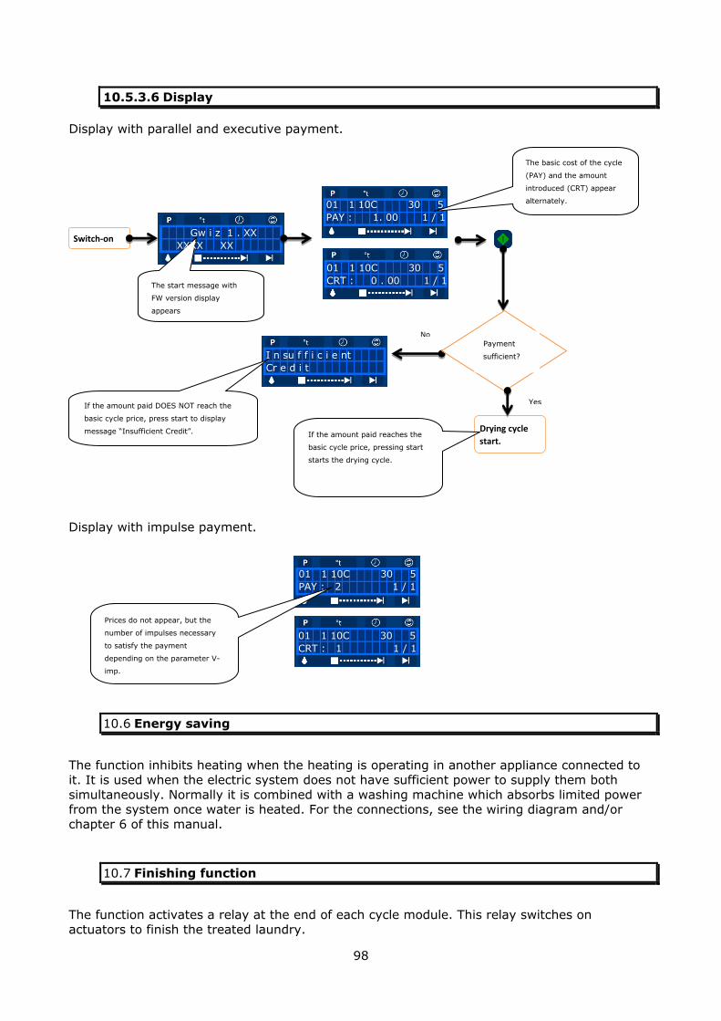
98
10.5.3.6 Display
Display with parallel and executive payment.
Display with impulse payment.
10.6 Energy saving
The function inhibits heating when the heating is operating in another appliance connected to
it. It is used when the electric system does not have sufficient power to supply them both
simultaneously. Normally it is combined with a washing machine which absorbs limited power from the system once water is heated. For the connections, see the wiring diagram and/or
chapter 6 of this manual.
10.7 Finishing function
The function activates a relay at the end of each cycle module. This relay switches on
actuators to finish the treated laundry.
Switch-on
The start message with
FW version display
appears
Gw i z 1 . XX
XXXX XX
01 1 10C 30 5
PAY : 1. 00 1 / 1
Drying cycle
start. If the amount paid reaches the
basic cycle price, pressing start
starts the drying cycle.
01 1 10C 30 5
CRT : 0 . 00 1 / 1
I n su f f i c i e nt
Cr e d i t
If the amount paid DOES NOT reach the
basic cycle price, press start to display
message “Insufficient Credit”.
The basic cost of the cycle
(PAY) and the amount
introduced (CRT) appear
alternately.
Payment
sufficient?
No
Yes
01 1 10C 30 5
PAY : 2 1 / 1
01 1 10C 30 5
CRT : 1 1 / 1
Prices do not appear, but the
number of impulses necessary
to satisfy the payment
depending on the parameter V-
imp.

99
10.8 Simplified check
10.8.1 General information
Mapping and operation of the 6-button keypad is modified in the simplified check. The START and STOP keys are active and the cycles with LOW-MEDIUM-HIGH temperature can be selected
with 3 keys combined with the single function.
10.8.2 Limits compared to the standard version
Compared to the standard version, this version of appliance: allows only 3 cycles to be used
does not allow any type of cycle programming before the keyboard is reset with
standard features does not allow the executive protocol to be used and therefore, the payment key/card
readers cannot be managed directly from the logic board. PAR and IMP type of payments (see parameter menu) remain active.
Requires dedicated firmware.
10.8.3 Comparison of the user interface.
The images below describe how the keyboard functions change when using the "simplified check".
Display Button < ( minus )
Button > (plus)
Enter Button
Mode button Start button
Button – Stop
Display
Button – Stop Start button
Button - low temperature cycle
Button - medium temperature cycle
Button - high temperature cycle
Standard check
Simplified check

100
10.8.4 Settings.
Configure the appliance with the "simplified check" as follows:
Program the microprocessor of the logic board with dedicated firmware and run RESET
Set dip switch 3 to OFF (see the digital inputs table in 6.9.5). Set dip switch 1 to ON or OFF (see the digital inputs table in 6.9.5) depending on the
paid or free use.
10.8.5 Programming
The only operation, in addition to selecting one of three cycles, START or STOP is RESET with the consequences described in paragraph 6.10.
Move dip switch 3 to ON to make changes to the cycles or the parameters. The keyboard
resumes the standard functions, including the MODE key not shown in the adhesive membrane dedicated to the simplified check. At this point the same operations as the standard version
are possible (except the selection of the EXE type of Sys-Pay) and therefore, refer to the explanations in chapter 6.
The settings referred to 10 programs appear in the cycles and parameters menu, however, as has already been mentioned, only the first 3 can be used.
ATTENTION: they must be consistent with that indicated on the adhesive membrane used.
Once the operations are complete, set dip switch 3 to OFF.
10.8.6 Preset cycles
Refer to paragraph 6.8.4 "description of the standard programs", as the first 3 of the same
table are used in the "simplified check".
101
11 ASSISTANCE SERVICE ADDRESSES, SPARE PARTS AND
CONSUMABLES ORDER.
Stamp of the maintenance agent
Stamp NOTES
Date
_ _ /_ _ / _ _
Date
_ _ /_ _ / _ _
Date
_ _ /_ _ / _ _
Date
_ _ /_ _ / _ _

102
12 LIST OF SPARE PARTS AND CONSUMABLES.
To identify the codes of the spare parts, use the exploded drawings (see technical attachment)
with relative part list.
Attention! Once the code has been identified, send regular order to the
manufacturer. Clearly indicate the model, serial number, power supply, and
frequency of the appliance. The code and the description of the spare part involved.
12.1 Recommended spare part list
Model kg 11 kg 14 kg 18 Kg 24
Electric heating resistance GR700002012020 GR700002012010 GR700002012020 GR700002012010
Gas electrodes GR50-GI-951516
T1 temperature probe GR700002000100
Proximity sensor NO (Reed) GR50-851000311
Flame control unit DBC579 GR700002000210
6-key board GR50-851000370
Gwiz control membrane GR420400000280
Door gasket GR700001011070
Transmission belts
return pulley motor
50Hz Unidirectional: GR700001012315 (XPZ 1112) Unidirectional and with inversion
GR700001012320 (XPZ 1237) With inversion: GR700001012310 (XPCS 1090)
60 Hz Unidirectional: _ _ _
Unidirectional and with GR inversion With inversion: GR7000012317 (XPZ1147)
Transmission belts
drum return pulley GR700001012290 (10*PJ 1549 LB)
12.2 Diagrams.
The part of the wiring diagrams, the exploded view for Kg 11, Kg 14, Kg 18 and Kg 24 models
is found in the technical attachment.
Attention! The technical attachment is an integral part of this manual.
103
12.3 Decommissioning
Refer to that indicated in this manual to dispose of the appliance.
12.3.1 Waste disposal
In compliance with Standards regarding waste disposal in force in the individual countries and
for respect of the environment in which the appliance is installed, all appliance parts must be divided in order to be disposed of or recovered separately. All parts of the appliance are
considered solid urban waste with exception of metal parts, which however, are not listed among special waste in most European countries.
12.3.2 Information for users
For the purpose and effects of Directives 2002/95/EC, 2002/96/EC and 2003/108/EC, relative to the reduction of use of dangerous substances in
electric and electronic appliances, as well as the disposal of waste” the crossed-bin symbol on the appliance indicates that the product must be collected
separately from other waste at the end of its useful life.
The separate collection of this appliance at the end of its life is organised and managed by the manufacturer.
If a new appliance is purchased, the user that wants to eliminate the used one must therefore contact the manufacturer and follow the system that the latter uses to allow separate
collection of the appliance at the end of its life. Correct separate collection of the appliance helps prevent possible negative effects to the environment and favours the recycling of
materials that make up the appliance. Illegal disposal of the product involves the application of administrative sanctions provided by law.
Attention! When the appliance is put out of service, remember to remove -
dismantle the door!
Refer to the WEEE European Directive regarding the recovery of parts (only for countries that are part of the European Union).
To dismantle the single parts and take them to a differentiated collection centre, refer to the cataloguing groups of the individual parts.
If required, the cataloguing groups can be found on the website: www.euwas.org