table of contents - mississippi department of...
TRANSCRIPT
Table of Contents
Bridge Safety Inspection ii Policy and Procedure Manual
Chapter 1 Introduction and Background .......................................... 1-1 1.1 Purpose and Scope ............................................................................................ 1-1 1.2 Federal and State Laws & Regulations ............................................................. 1-2
1.2.1 National Bridge Inspection Standards ........................................................ 1-2 1.2.2 The Mississippi Code of 1972 .................................................................... 1-2
1.3 Mississippi Department of Transportation........................................................ 1-3 1.3.1 Mississippi Transportation Commission .................................................... 1-3 1.3.2 Responsibilities ........................................................................................... 1-3 1.3.3 Organizational Charts ................................................................................. 1-4 1.3.4 Bridge Division ........................................................................................... 1-5
1.3.4.1 Background .................................................................................................... 1-5 1.3.4.2 Bridge Management, Ratings & Inventory Section ....................................... 1-5
1.3.5 MDOT Districts .......................................................................................... 1-7 1.3.5.1 MDOT Districts Map ..................................................................................... 1-7 1.3.5.2 District Bridge Safety Inspection Personnel .................................................. 1-8
Chapter 2 Bridge Inspections and Reports ....................................... 2-1
2.1 Types of Bridge Inspections ............................................................................. 2-1 2.1.1 Initial Inspections ........................................................................................ 2-1 2.1.2 Routine Inspections ..................................................................................... 2-1 2.1.3 Damage Inspections .................................................................................... 2-2 2.1.4 In-Depth Inspections ................................................................................... 2-2 2.1.5 Fracture-Critical Inspections ....................................................................... 2-2 2.1.6 Underwater Inspections .............................................................................. 2-3 2.1.7 Special Inspections...................................................................................... 2-4
2.2 Complex Bridges .............................................................................................. 2-4 2.3 Assessment for Bridge Scour ............................................................................ 2-4 2.4 Bridge Inspection Equipment ........................................................................... 2-5
2.4.1 Standard Equipment .................................................................................... 2-5 2.4.2 Specialized Equipment................................................................................ 2-6
2.4.2.1 Survey Equipment .......................................................................................... 2-6 2.4.2.2 Non-Destructive Testing Methods ................................................................. 2-6 2.4.2.3 Underwater Inspection Equipment ................................................................. 2-6 2.4.2.4 Underbridge Inspection Vehicles ................................................................... 2-7
2.4.3 Safety Considerations ................................................................................. 2-7 2.4.4 Maintenance of Traffic ............................................................................... 2-8 2.4.5 Railroads ..................................................................................................... 2-8
2.5 Bridge Inspection Procedures ........................................................................... 2-8 2.5.1 Examples of Good Inspection Practices ..................................................... 2-9 2.5.2 Inspection Photographs ............................................................................. 2-10
2.6 Reporting of Critical Bridge Damage or Deficiencies .................................... 2-12 2.6.1 Critical Deficiency Process ....................................................................... 2-13 2.6.2 Hazardous Deficiency Process .................................................................. 2-15 2.6.3 MDOT’s Comprehensive Emergency Transportation Response Plan ...... 2-15
2.7 Bridge Inspection Reports............................................................................... 2-15 2.7.1 Minimum Requirements ........................................................................... 2-16 2.7.2 Bridge Maintenance Report ...................................................................... 2-16

Table of Contents
Bridge Safety Inspection iii Policy and Procedure Manual
Chapter 3 Bridge Inspection File (Records) ...................................... 3-1 3.1 Purpose of Bridge Records ............................................................................... 3-1 3.2 Components of Bridge Records ........................................................................ 3-2
Chapter 4 Load Rating and Analysis ................................................. 4-1
4.1 MDOT Load Rating and Posting Policy ........................................................... 4-1 4.1.1 Criteria for Load Rating .............................................................................. 4-1
4.1.1.1 Loads .............................................................................................................. 4-2 4.1.1.2 Impact Factors ................................................................................................ 4-2 4.1.1.3 Methods.......................................................................................................... 4-3 4.1.1.4 Software ......................................................................................................... 4-3
4.1.2 Criteria for Posting or Closing .................................................................... 4-3 4.1.2.1 Statues and Regulations Regarding Bridge Restrictions ................................ 4-3 4.1.2.2 Bridge Posting Evaluation ............................................................................. 4-4
4.1.3 Procedures for Application, Modification, or Removal of Weight Restrictions ................................................................................................. 4-5
4.2 Hauling Permits (This section to be added at a later date) ............................... 4-6 Chapter 5 National Bridge Inventory (NBI) ..................................... 5-1
5.1 Bridge Inventory Data....................................................................................... 5-1 5.1.1 Inventory Items ........................................................................................... 5-1 5.1.2 Condition Items ........................................................................................... 5-2 5.1.3 Appraisal Items ........................................................................................... 5-3 5.1.4 Pontis ........................................................................................................ 5-3
5.2 FHWA Reporting Guidelines ........................................................................... 5-4 5.2.1 Structure Inventory and Appraisal .............................................................. 5-4 5.2.2 Data Entry Requirements ............................................................................ 5-4
5.3 Structure Identification ..................................................................................... 5-4 5.3.1 Labeling Structures ..................................................................................... 5-4 5.3.2 Structure Keys ............................................................................................. 5-5 5.3.3 Bridge Number/Mile Post ........................................................................... 5-5 5.3.4 Structure Number ........................................................................................ 5-5
Chapter 6 Quality Control and Quality Assurance .......................... 6-1
6.1 Quality Control Procedures............................................................................... 6-1 6.1.1 Organization and Staffing ........................................................................... 6-1
6.1.1.1 Bridge Management, Ratings & Inventory Section ....................................... 6-1 6.1.1.2 MDOT Districts ............................................................................................. 6-3
6.1.2 Annual Meeting with Bridge Inspection Staff ............................................ 6-6 6.2 Quality Assurance Procedures .......................................................................... 6-6
6.2.1 BIPM Annual Review ................................................................................. 6-6 6.2.1.1 Field Inspections ............................................................................................ 6-7 6.2.1.2 Office Review ................................................................................................ 6-7
6.2.2 District Close-Out Meeting ......................................................................... 6-8 6.2.3 District Summary Report ............................................................................ 6-8

Table of Contents
Bridge Safety Inspection iv Policy and Procedure Manual
6.2.4 Disqualification ........................................................................................... 6-8 6.2.4.1 Out-of-Tolerance ............................................................................................ 6-8 6.2.4.2 Reasons for Disqualification .......................................................................... 6-9 6.2.4.3 Disqualification Procedures ........................................................................... 6-9
6.3 Training and Continuing Education ................................................................ 6-10 6.3.1 National Highway Institute ....................................................................... 6-10 6.3.2 Qualifications Database ............................................................................ 6-11
Appendix A
References .................................................................................................................... A-1 Appendix B
NBIS Code of Federal Regulations Chapter 23 Highways – Part 650 ........................ B-1 Appendix C
Abbreviations ............................................................................................................... C-1 Definitions.................................................................................................................... C-4
Appendix D
Standard Inspection Equipment ................................................................................... D-1 Appendix E
Sample Forms ............................................................................................................... E-1 Bridge Maintenance Repair Request (BRD005) MDOT Standard Bridge Inspection Form (BRD006b) MDOT Standard Box Culvert Inspection Form (BRD006c) MDOT Standard Truss Inspection Form (BRD006t) Bridge Critical Deficiency Report (BRD008) Bridge Hazardous Deficiency Report (BRD009) Bridge Inspector Experience and Training Record Scour Critical Bridge – Plan of Action Fracture-Critical Bridge Inspection Procedure
Appendix F
AASHTO and State-Specific CoRe Elements .............................................................. F-1 Appendix G
Engineering Services Contract and Scope of Work for Underwater Bridge Inspection Services ........................................................................................................................ G-1
Appendix H
Mississippi State Legal Load Truck Illustrations ........................................................ H-1

Bridge Safety Inspection 1-1 Policy and Procedure Manual
Chapter 1 Introduction and Background 1.1 Purpose and Scope The primary purpose of the Mississippi Department of Transportation Bridge Safety Inspection Policy and Procedure Manual (Manual) is to organize and compile information on the policies and procedures of the Mississippi Department of Transportation (MDOT) as related to their bridge safety inspection program to ensure: ● Bridges are adequately inspected and maintained in order to maximize public safety.
● Compliance with all requirements of the Federal Highway Administration (FHWA), the National Bridge Inspection Standards (NBIS) and the state of Mississippi.
● Proper management and quality control of bridge safety inspections, bridge inventory data, load ratings and load postings.
The MDOT has a decentralized bridge safety inspection program that follows the guidelines and standards established by the FHWA and the American Association of State Highway and Transportation Officials (AASHTO). Each district is responsible for the management, administration, and inspection of all bridges under its maintenance jurisdiction. The Bridge Division is responsible for the overall guidance and coordination of the MDOT’s bridge safety inspection program. The Manual is intended to provide guidance to all MDOT personnel involved in bridge safety inspection activities. In the event of conflicting information or requirements between the Manual and the NBIS, the NBIS shall govern. The Manual is not a static document, and will be updated periodically with revisions based on feedback from employees within the MDOT, as well as practices outlined by the FHWA and the state of Mississippi. The Manual provides guidance on the responsibilities of the MDOT; procedures and administrative requirements to ensure public safety and compliance with all applicable laws and statutes; quality control (QC) and quality assurance (QA) guidelines; and technical information regarding bridge safety inspections, load ratings, and load postings. The Manual is intended to provide information regarding inspections of bridges with a span of greater than 20 feet. Provisions are not included for local bridges not maintained by the MDOT, pedestrian bridges, federally owned bridges, bridges used solely for railway or rail transit, or public utilities that are not related to public highways. The Manual is not intended to supplant proper training or the exercise of judgment by a professional engineer, and states only the minimum requirements necessary to provide for

Chapter 1 – Introduction and Background
Bridge Safety Inspection 1-2 Policy and Procedure Manual
public safety. The individual districts of the MDOT may require higher standards for inspection, load rating or the testing of materials than the minimum requirements. In-depth background material and supporting information may be found in the references listed in Appendix A. 1.2 Federal and State Laws & Regulations
1.2.1 National Bridge Inspection Standards
The NBIS are mandated by federal law and are intended to ensure the proper inspection of the nation’s bridges with spans greater than 20 feet in length on public roads. The NBIS are included in Subpart C of Part 650 of the Code of Federal Regulations, Title 23 – Highways. A copy of the current NBIS is included in Appendix B and is also available for download at: http://frwebgate.access.gpo.gov/cgi-bin/get-cfr.cgi?TITLE=23&PART=650&SUBPART=C&TYPE=PDF The NBIS were developed after the 1968 Federal Highway Act became effective and were first published as a notice in the Federal Register, Volume 36, No. 81, Page 7851 on April 27, 1971. In the latest revisions to the NBIS, published in the Federal Register in December 2004 (Volume 69, Number 239) and now part of the Code of Federal Regulations (Title 23, Part 650), the FHWA clarified language that was vague or ambiguous, reorganized the standards into a more logical sequence, and made it easier for those administering the highway bridge inspection programs at the state and federal levels to understand the regulations. In addition to administering the NBIS, the FHWA gives policy guidance, establishes criteria and priorities for matching funds under various programs, and reviews the results of those programs for compliance with the NBIS through its annual compliance review.
1.2.2 The Mississippi Code of 1972
The most recent version of The Mississippi Code of 1972, as Amended, can be accessed at http://michie.com/mississippi/ or http://www.mscode.com/. Since the Code is extensive and not static, only references to relevant sections of the Code are provided in the Manual. For the most current laws and regulations, it is recommended that the Code be accessed at one of the web sites listed above. The most relevant section of the Code as related to bridge safety inspections is Title 65: Highways, Bridges, and Ferries.

Chapter 1 – Introduction and Background
Bridge Safety Inspection 1-3 Policy and Procedure Manual
1.3 Mississippi Department of Transportation
1.3.1 Mississippi Transportation Commission
The state of Mississippi vests oversight of its highway transportation resources and operations in the three-member elected Mississippi Transportation Commission (MTC). The MTC appoints the Executive Director of the MDOT. The Executive Director administers policies approved by the MTC and has full supervision over administrative and technical matters relating to highway construction, maintenance, and weight enforcement. The Executive Director appoints the directors of the MDOT’s four central operating offices (Administrative Services, Highways, Enforcement, and Intermodal Planning).
1.3.2 Responsibilities
The MDOT has federal and state statutory responsibilities for the safety and inspections of public road bridges in Mississippi on state routes, U.S. routes and interstate highways. Some of the more critical of these responsibilities include assurance of compliance with the NBIS, proper bridge restrictions for vehicle size and weight, administration of federal funds for NBIS inspections, and the reporting of National Bridge Inventory (NBI) bridge data to the FHWA.

Chapter 1 – Introduction and Background
Bridge Safety Inspection 1-4 Policy and Procedure Manual
1.3.3 Organizational Charts
Figure 1 – MDOT Organizational Structure
Mississippi Transportation Commission
Office of Administrative Services
Deputy Executive Director
Office of Highways Deputy Executive
Director/ Chief Engineer
Office of Enforcement
Pre-Construction
Bridge Division
Bridge Management, Ratings & Inventory
Section
Office of Intermodal Planning
District Offices
Tupelo District 1
Batesville District 2
Yazoo City District 3
Newton District 5
Hattiesburg District 6
McComb District 7
Hydraulics Section
Design & Plan Preparation Section
CADD/Computer Systems Section
Estimating Section
Administrative Section
Executive Director
Foundations Section

Chapter 1 – Introduction and Background
Bridge Safety Inspection 1-5 Policy and Procedure Manual
Figure 2 – MDOT Bridge Division Organizational Structure
1.3.4 Bridge Division
1.3.4.1 Background
The Bridge Division is administered through the Office of Highways and has approximately 50 engineers, technicians, and staff personnel under the direction of the State Bridge Engineer, who are responsible for the safety of existing bridges and the development of quality, cost effective and safe bridges for the state. Functionally, the Bridge Division is separated into seven sections: Bridge Management, Ratings & Inventory; Hydraulics; Foundations; Design & Plan Preparation; CADD/Computer Systems; Estimating; and Administrative.
1.3.4.2 Bridge Management, Ratings & Inventory Section
The Bridge Management, Ratings & Inventory Section consists of four registered professional engineers and two NICET certified Bridge Safety Inspectors, managed by the Bridge Inspection Program Manager (BIPM). This section is responsible for the management of data for over 5,600 state-owned bridges and the MDOT bridge intranet site. In addition, this section performs bridge load ratings and coordinates with the Permits Division of the Office of Enforcement in the evaluation of vehicles for oversize and overweight permits and reports load and clearance restrictions and emergency closures to the Office of Enforcement.
State Bridge Engineer District Engineer
Bridge Inspection Program Manager
(BIPM)
Assistant District Engineer -
Maintenance
District Bridge Inspection Engineer
(DBIE)
Bridge Inspection Team Coordinator
(BITC)
District Bridge Inspector(s) (DBI)
Bridge Load Rating Engineer (BLRE)

Chapter 1 – Introduction and Background
Bridge Safety Inspection 1-6 Policy and Procedure Manual
The BIPM works under the direction of the State Bridge Engineer. Qualifications for the BIPM are listed in Section 6.1.1.1.1. The BIPM has the following responsibilities: ● Overall management of the MDOT’s bridge inspection program.
● Responsible for inspection policies, procedures and maintenance of the Manual and all related forms.
● QC and QA for inspection, inspection records, load rating and load posting.
● QC and QA of qualifications, experience, and training of all MDOT employees performing bridge safety inspections.
● Management of bridge inventory data and reporting NBI data to the FHWA.
● Management of the underwater bridge inspection (UWI) program.
● Management and monitoring of bridge scour assessments, recommendations, and Plans of Action (POA).
● Management of load posting requirements.
● Management of the training program for MDOT employees performing bridge safety inspections.
● Development of inspection procedures for complex bridges or bridges having fracture-critical members (FCM).
The Bridge Load Rating Engineer (BLRE) works under the direction of the BIPM. Qualifications for the BLRE are listed in Section 6.1.1.1.2. The BLRE has the following responsibilities: ● Perform load ratings for state maintained bridges.
● Determine weight restrictions for state maintained bridges.
● Report recommended changes in weight restrictions to the BIPM.
● Determine capacities for special load permits and report to the Permits Division of the Office of Enforcement.
● Report load and clearance restrictions or emergency closures to the Commercial Motor Vehicle Enforcement Division of the Office of Enforcement.
● Assist the BIPM with the QC/QA for inspection, inspection records, load rating and load posting.

Chapter 1 – Introduction and Background
Bridge Safety Inspection 1-7 Policy and Procedure Manual
1.3.5 MDOT Districts
The MDOT has six districts located throughout the state. Each district is responsible for conducting the required type of safety inspection for all bridges under its maintenance jurisdiction, and the reporting of all NBI data and inspection reports to the BIPM.
1.3.5.1 MDOT Districts Map
Figure 3 – MDOT Districts
Chapter 1 – Introduction and Background
Bridge Safety Inspection 1-8 Policy and Procedure Manual
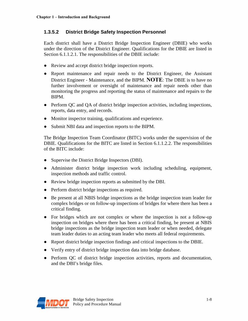
1.3.5.2 District Bridge Safety Inspection Personnel Each district shall have a District Bridge Inspection Engineer (DBIE) who works under the direction of the District Engineer. Qualifications for the DBIE are listed in Section 6.1.1.2.1. The responsibilities of the DBIE include: ● Review and accept district bridge inspection reports.
● Report maintenance and repair needs to the District Engineer, the Assistant District Engineer - Maintenance, and the BIPM. NOTE: The DBIE is to have no further involvement or oversight of maintenance and repair needs other than monitoring the progress and reporting the status of maintenance and repairs to the BIPM.
● Perform QC and QA of district bridge inspection activities, including inspections, reports, data entry, and records.
● Monitor inspector training, qualifications and experience.
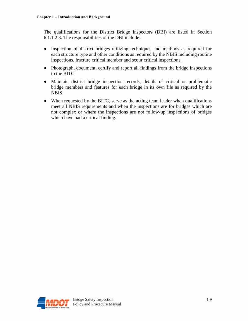
● Submit NBI data and inspection reports to the BIPM. The Bridge Inspection Team Coordinator (BITC) works under the supervision of the DBIE. Qualifications for the BITC are listed in Section 6.1.1.2.2. The responsibilities of the BITC include: ● Supervise the District Bridge Inspectors (DBI).
● Administer district bridge inspection work including scheduling, equipment, inspection methods and traffic control.
● Review bridge inspection reports as submitted by the DBI.
● Perform district bridge inspections as required.
● Be present at all NBIS bridge inspections as the bridge inspection team leader for complex bridges or on follow-up inspections of bridges for where there has been a critical finding.
● For bridges which are not complex or where the inspection is not a follow-up inspection on bridges where there has been a critical finding, be present at NBIS bridge inspections as the bridge inspection team leader or when needed, delegate team leader duties to an acting team leader who meets all federal requirements.
● Report district bridge inspection findings and critical inspections to the DBIE.
● Verify entry of district bridge inspection data into bridge database.
● Perform QC of district bridge inspection activities, reports and documentation, and the DBI’s bridge files.
Chapter 1 – Introduction and Background
Bridge Safety Inspection 1-9 Policy and Procedure Manual
The qualifications for the District Bridge Inspectors (DBI) are listed in Section 6.1.1.2.3. The responsibilities of the DBI include: ● Inspection of district bridges utilizing techniques and methods as required for
each structure type and other conditions as required by the NBIS including routine inspections, fracture critical member and scour critical inspections.
● Photograph, document, certify and report all findings from the bridge inspections to the BITC.
● Maintain district bridge inspection records, details of critical or problematic bridge members and features for each bridge in its own file as required by the NBIS.
● When requested by the BITC, serve as the acting team leader when qualifications meet all NBIS requirements and when the inspections are for bridges which are not complex or where the inspections are not follow-up inspections of bridges which have had a critical finding.
Bridge Safety Inspection 2-1 Policy and Procedure Manual
Chapter 2 Bridge Inspections and Reports The NBIS establishes guidelines for bridge safety inspection frequencies and procedures. All MDOT maintained bridges shall be inspected in accordance with the requirements of the NBIS. The most current version of the NBIS is included in Appendix B. (See Section 1.2.1 for more information on the NBIS) 2.1 Types of Bridge Inspections The following types of bridge safety inspections are described in the AASHTO Manual for Bridge Evaluation (MBE). All types of inspections shall be conducted in the presence of a NBIS qualified team leader.
2.1.1 Initial Inspections
The Initial Inspection of a bridge is performed as it becomes part of the bridge inventory or after a major rehabilitation when the year rebuilt is coded greater than zero. Initial Inspections provide Structure Inventory and Appraisal (SI&A) data along with bridge element information and baseline structural condition. Initial Inspections usually begin in the office with the construction plans and route information then proceed to the field for verification of the as-built conditions. 2.1.2 Routine Inspections
The Routine Inspection is a regularly scheduled inspection consisting of observations and/or measurements needed to determine the physical and functional condition of the bridge, to identify any changes from initial or previously recorded conditions, and to ensure that the structure continues to satisfy present service requirements. The Routine Inspection identifies the current structural and hydraulic adequacy and condition of the bridge. Included in the Routine Inspection report are repair recommendations and recommendations for further analysis or investigation. Each bridge shall receive a Routine Inspection performed at regular intervals not to exceed 24 months (two years). Certain bridges that may be inspected at intervals greater than 24 months (not to exceed 48 months) shall be based upon selected criteria established by the State Bridge Engineer and are subject to written approval by the FHWA. These bridges must meet the requirements of Paragraph 5 of the FHWA Technical Advisory T5140.21, dated September 16, 1988 (See Appendix A). The BIPM has the authority to establish Routine Inspection intervals of less than 24 months. Any bridge with a main timber component in the deck, superstructure or substructure and bridges that are posted for weight restrictions shall be inspected at an interval not to exceed 12 months.

Chapter 2 – Bridge Inspections and Reports
Bridge Safety Inspection 2-2 Policy and Procedure Manual
2.1.3 Damage Inspections
Damage Inspections may be necessary immediately after an emergency, or scheduled to monitor certain conditions that may develop after environmental or man-inflicted incidents such as traffic/vehicle damage, boat/barge damage, flooding, or fire. Any condition found to be hazardous or dangerous to the traveling public or which endangers the structure shall be immediately reported following the procedures outlined in Section 2.6. The State Bridge Engineer is to be consulted if any unusual repairs require review or work beyond the scope of the district. Repairs beyond the scope and ability of the district crews may be performed by contract. See Section 2.6.3 for an explanation of the MDOT’s Comprehensive Emergency Transportation Response Plan (CETRP). 2.1.4 In-Depth Inspections
An In-Depth Inspection is a close-up, hands-on inspection of one or more members above or below the water level to identify any deficiencies not readily detectable using routine inspection procedures. This type of inspection can be scheduled independently of a Routine Inspection, though generally at a longer interval, or it may be a follow-up for Damage or Initial Inspections. In-Depth Inspections are required for any structural unit that contains a fracture-critical member and/or a component with a known deficiency such as a steel girder with section loss or a pre-stressed concrete girder with shear cracks. Bridges with structurally non-redundant members and/or fatigue prone details also shall receive an In-Depth Inspection. In addition, timber bridge components shall require a complete In-Depth Inspection as part of the regularly scheduled Routine Inspections. In-Depth Inspections are to be performed at intervals not to exceed 12 months. 2.1.5 Fracture-Critical Inspections A Fracture-Critical Inspection is an in-depth evaluation of critical bridge components performed in accordance with procedures developed for that structure. These inspection procedures identify the location of fracture-critical members (FCMs) and describe the inspection requirements, and are outlined in the bridge record for each structure with a FCM. Information regarding identification of FCMs and developing inspection procedures is provided in the FHWA Report, Inspection of Fracture Critical Bridge Members. For the MDOT Fracture-Critical Bridge Inspection Procedure form, See Appendix E. An FCM is defined as a steel member in tension, or with a tension element, whose failure would most likely cause a portion of or the entire bridge to fail catastrophically. Per MDOT guidelines, Fracture-Critical Inspections are to be performed at intervals not to exceed 12 months (one year).

Chapter 2 – Bridge Inspections and Reports
Bridge Safety Inspection 2-3 Policy and Procedure Manual
Fracture-Critical Inspections may require the use of ultrasonic testing (UT) equipment or non-destructive evaluation (NDE) techniques. Bridges with FCMs are identified by Item 92A in the NBI. 2.1.6 Underwater Inspections
Underwater members must be inspected to the extent necessary to determine with certainty that their condition has not compromised the structural safety of the bridge. An Underwater Inspection (UWI) is performed on bridges with structural elements which are underwater at a depth of greater than 3 feet, and are not otherwise accessible for inspection. A UWI is required for underwater elements that cannot be visually evaluated or examined by feel for condition or integrity due to excessive water depth or turbidity. Underwater inspection procedures shall identify, locate, and describe underwater elements for each bridge requiring a UWI. All structures with underwater elements must receive routine underwater inspections at intervals not to exceed 60 months (or 72 months with FHWA approval). This is the maximum interval permitted between UWI’s for bridges which are both in excellent condition underwater and which are located in passive, non-threatening environments. Certain bridges may require an inspection of underwater structural elements at less than 60 month intervals. These bridges will be evaluated for a reduced frequency on a case by case basis depending on its configuration, type and severity of deterioration, as well as the location and number of deteriorated elements. Other factors to be considered are channel condition, structure load path redundancy, age, scour and bank deterioration. Generally when individual substructure elements are rated poor (NBI condition rating less than 5), frequency reduction is considered. The BIPM/Bridge Division may call for a twenty-four (24) to thirty-six (36) month inspection frequency based upon these conditions. Scour and embankment deterioration by itself can trigger a reduced inspection frequency depending on the foundation type and amount of scour observed. Inspectors may also recommend a reduced frequency based on other observed deficiencies. Bridges requiring a UWI are identified by Item 92B in the NBI. The MDOT utilizes the services of a qualified and experienced diving firm to perform all Underwater Inspections. Divers employed by the firm and conducting the inspections shall meet the requirements of §650.309(d). See Appendix G for a typical Engineering Services Contract and Scope of Work for Underwater Bridge Inspection Services. Underwater Inspections are classified by three levels, depending on requirements and needs for a specific structure:
Level I: Consists of a “swim-by” overview of the structure, at arm's length, with minimal cleaning to remove marine growth. All underwater elements are to receive this level of inspection at a minimum.

Chapter 2 – Bridge Inspections and Reports
Bridge Safety Inspection 2-4 Policy and Procedure Manual
Level II: A detailed “sampling” inspection, which requires that portions of the substructure be cleaned of marine growth. Typically, at least 10 percent of the UWI should meet Level II requirements. Level III: Consists of a highly detailed inspection of critical structural elements that may have extensive damage or deterioration or that may require repairs or replacement.
2.1.7 Special Inspections
A Special Inspection is an inspection scheduled at the discretion of the MDOT Bridge Division. It is used to monitor a particular known or suspected deficiency, such as foundation settlement, scour, member condition, or the public’s use of a load-posted bridge, and can be performed by any qualified person familiar with the bridge and available to accommodate the assigned inspection frequency. The determination of an appropriate Special Inspection frequency should consider the severity of the known deficiency. The BIPM is responsible for determining if a Special Inspection is required and the Special Inspection intervals. Bridges requiring a Special Inspection are identified by Item 92C in the NBI. Special Inspections usually are not sufficiently comprehensive to meet NBIS requirements for Routine Inspections. Any bridge having known deficiencies, that is in questionable condition, or that is subjected to unusual stress, strain, or hazard by reason of repetitive overloads, collision damage, stream degradation, shifting of stream channel or other known reasons, shall receive a Special Inspection as often as necessary to accurately assess any potential hazardous conditions.
2.2 Complex Bridges
Complex bridges are bridges which have unique or special features that require additional attention. Inspection procedures shall identify specialized inspection requirements and additional inspector training and experience necessary to inspect complex bridges. Examples of complex bridges include cable-stayed bridges, suspension bridges, and movable bridges. Per MDOT guidelines, Routine Inspections of complex bridges are to be performed at intervals not to exceed 12 months (one year). The BIPM is responsible for determining complex bridge inspection procedures. The BITC, as a registered professional engineer, is required to serve as the inspection team leader for all inspections of complex bridges.
2.3 Assessment for Bridge Scour
In order to prevent the loss of a bridge due to scour failure, it is necessary to identify those bridges most likely to be vulnerable to scour. Performing a scour assessment and developing a scour Plan of Action (POA) helps the bridge inspectors and owners to

Chapter 2 – Bridge Inspections and Reports
Bridge Safety Inspection 2-5 Policy and Procedure Manual
concentrate efforts and remedial actions to mitigate the conditions at bridges susceptible to the effects of scour. A scour critical bridge is one whose foundation has been determined to be unstable for the predicted scour conditions. The results of the calculated scour assessment are to be used to determine a bridge’s susceptibility to scour. Information from past inspections and the scour assessments are used together for the evaluation of the overall safety of the bridge. The NBIS require that all bridges determined to be scour critical have a written scour POA. The POA details the procedures for monitoring known and potential deficiencies and for addressing critical findings, as well as procedures for closure of the roadway, if necessary. A sample POA for a scour critical bridge is included in Appendix E. Evaluating Scour at Bridges, Hydraulic Engineering Circular No. 18 (HEC-18), dated May 2001, presents the state of knowledge and practice for the design, evaluation and inspection of bridges for scour. Namely, the purpose of this document is to provide guidelines for the following: designing new and replacement bridges to resist scour; evaluating existing bridges for vulnerability to scour; inspecting bridges for scour; improving the state-of-practice of estimating scour at bridges. There are two companion documents, Stream Stability at Highway Structures (HEC-20), dated March 2001, and Bridge Scour and Stream Instability Countermeasures (HEC-23), dated March 2001. Bridges determined to be scour critical shall be inspected after every major runoff event to the extent necessary to ensure bridge foundation integrity. 2.4 Bridge Inspection Equipment Utilizing the proper inspection equipment is necessary to maintain the safety of the bridge inspectors and the traveling public. Inspectors should never try to substitute improper inspection equipment in the interest of saving time or money. Also, the inspector shall be familiar with every piece of equipment and how to use and operate it properly and safely. Each district is responsible for providing inspectors with the proper equipment, training, and oversight.
2.4.1 Standard Equipment
See Appendix D for a comprehensive list of inspection equipment which should be provided to each district bridge inspection team. All equipment provided shall be necessary to complete thorough bridge inspections and shall meet Occupational Safety and Health Administration (OSHA) safety standards. Standard bridge inspection equipment is divided into eight categories: Safety Equipment (including Personal Protective Equipment), General Tools, Cleaning Tools, Visual Aid Tools, Measuring Tools, Documentation Tools, Access Tools, and Miscellaneous Equipment.
Chapter 2 – Bridge Inspections and Reports
Bridge Safety Inspection 2-6 Policy and Procedure Manual
2.4.2 Specialized Equipment
For the Routine Inspection of a common bridge, special equipment is usually not necessary. However, certain inspection activities may require special tools. The inspector shall be familiar with special equipment and its application.
2.4.2.1 Survey Equipment
Special circumstances may require the use of a transit, a level, an incremental rod, or other survey equipment. This equipment can be used to establish a component's exact location relative to other components, as well as an established reference point. In addition, Global Positioning System (GPS) coordinates may be used to establish the location of a bridge.
2.4.2.2 Non-Destructive Testing Methods Non-Destructive Testing (NDT) is the in-place examination of a material for structural integrity without damaging the material. NDT equipment allows the inspector to “see” inside a bridge element and assess deficiencies that may not be visible with the naked eye. Generally, a trained technician is necessary to conduct NDT and interpret the results. NDT work may be contracted out. NDT methods which are performed by the MDOT Bridge Division include the following: ● Dye Penetrant (PT) – This procedure involves applying a penetrant liquid to the
surface by spray or brush. The penetrant will seek out and enter small openings. After sufficient drying a white developer is applied. The colored (usually red) penetrant remaining in the discontinuity bleeds out forming a highly visible, contrasting indication on the test surface. PT is simple to use and can be used on any non-porous material, however the surface must be clean and paint free, and only surface defects can be detected using this method.
● Ultrasonic Testing (UT) – Ultrasonic inspection is used to evaluate the internal
condition or thickness of materials. Typical discontinuities that are detectable by use of ultrasonic testing include laminations, cracks, and many of the surface and subsurface weld discontinuities. An ultrasonic thickness gage can be used to measure the thickness of a steel element using a probe which emits and receives sound waves.
2.4.2.3 Underwater Inspection Equipment
When the waterway is shallow (less than 3 feet), underwater inspection can be performed from above water with a simple probe. Probing can be performed using a range pole, piece of reinforcing steel, a survey rod, a folding rule, or even a tree limb.

Chapter 2 – Bridge Inspections and Reports
Bridge Safety Inspection 2-7 Policy and Procedure Manual
When the waterway is deep (greater than 3 feet), the UWI must be performed by a diver who is qualified and certified per the NBIS. This requires special diving equipment that can include a working platform or boat, air supply systems, radio communication, and sounding equipment. 2.4.2.4 Underbridge Inspection Vehicles
An underbridge inspection vehicle is a specialized bucket truck with an articulated boom designed to reach under a structure while parked on the bridge deck. The MDOT owns five underbridge inspection vehicles, which are used by the district bridge inspectors and Bridge Division personnel on an as needed basis. The Bridge Management, Ratings & Inventory Section owns an Aspen Aerials UB60 and all personnel of the Bridge Management, Ratings & Inventory Section are certified to operate the unit. Districts 1, 2, and 6 each own and operate an Aspen Aerials UB30. District 5 owns and operates a MOOG inspection/work platform crane.
2.4.3 Safety Considerations
Before the bridge inspection begins, an equipment inspection should be performed. The inspector should check all the equipment and verify that it is in good working condition with no defects or problems. When necessary, safety harnesses with shoulder, leg, and waist straps of approved OSHA design should be used as personal fall protection in conjunction with appropriate lanyards and tie off devices. At a minimum, all access equipment should be inspected regularly as per the manufacturer’s guidelines, and should be replaced if worn or damaged. If rigging or scaffolding is being used, it should be checked to ensure that it was installed properly and all cables and planks are secured tightly. When using an underbridge inspection vehicle, all operators should be properly trained. If the inspector is not familiar with the inspection vehicle being used, he/she should take the time required to become accustomed to the operation. When operating any inspection vehicle, inspectors should always be aware of any overhead power lines or any other hazards that may exist. It is also important to be aware of any restrictions on the vehicle, such as weight limits for the bucket, support surface slope limits, wind speed restrictions, and reach limitations. Do not boom out into unsafe areas such as unprotected traffic lanes or near electrical lines. When climbing or using an underbridge inspection vehicle over water, the requirements of OSHA Standard No. 1926.106 shall apply: (a) Employees working over or near water, where the danger of drowning exists, shall
be provided with U.S. Coast Guard-approved life jacket or buoyant work vests.
Chapter 2 – Bridge Inspections and Reports
Bridge Safety Inspection 2-8 Policy and Procedure Manual
(b) Prior to and after each use, the buoyant work vests or life preservers shall be inspected for defects which would alter their strength or buoyancy. Defective units shall not be used.
(c) Ring buoys with at least 90 feet of line shall be provided and readily available for emergency rescue operations. Distance between ring buoys shall not exceed 200 feet.
(d) At least one lifesaving skiff shall be immediately available at locations where employees are working over or adjacent to water.
2.4.4 Maintenance of Traffic
When using an access vehicle or special equipment, it may be necessary to close a lane of traffic on or underneath the bridge. Each district has its own traffic personnel who are able to provide proper set up and maintenance of traffic (MOT). Guidelines for proper MOT are set forth in the Manual on Uniform Traffic Control Devices (MUTCD) (see Appendix A). The BITC is responsible for scheduling any required MOT with the district ahead of time. A shadow vehicle with a truck mounted attenuator (TMA) parked behind the inspection vehicle is used to prevent vehicles from entering the work zone and striking the inspection vehicle or any inspectors if a motorist drifts into the lane closure. A shadow vehicle should generally be employed any time a shoulder or travel lane will be occupied by workers or equipment. On some inspections, police assistance may be helpful and even required, especially if work is being performed at night. The presence of a patrol car aids in slowing and controlling the public. At a signalized intersection near a job site, a police officer may be required to ensure traffic flows properly and smoothly. 2.4.5 Railroads
For bridges over railroads, coordination with the railroad owner is required to ensure that a flagman is available to warn inspectors of approaching trains. It is the responsibility of the BITC to coordinate and schedule railroad flagmen and to ensure that all proper procedures and requirements are met when inspecting bridges over or near railroads.
2.5 Bridge Inspection Procedures
Each district shall ascertain their needs in order that each bridge in their jurisdiction receives thorough Routine Inspections. Inspections shall be performed by at least two qualified inspectors, one of whom must meet the NBIS definition of a team leader (see Appendix B). All inspections are performed in teams for safety purposes and to provide assistance in the inspection procedure.

Chapter 2 – Bridge Inspections and Reports
Bridge Safety Inspection 2-9 Policy and Procedure Manual
Plan. The first step is to plan the inspection. The inspection team should make sure all equipment is available, and should schedule MOT with the district, if needed. The BITC is responsible for providing all equipment and scheduling. Safety Features. The inspection should include a thorough review of all safety features such as railings, guardrails and signs, including advance warning and posting signs. Safety features shall be given particular attention during the Initial Inspection. Visual Inspection. A complete visual inspection of the bridge should be performed, noting all defects and irregularities. Maintenance. The inspectors should note any maintenance items such as clogged scuppers or debris in the stream channel. A Bridge Maintenance Repair Request (form BRD005) should be filled out and submitted with the inspection report, if required. Soundings. For bridges over water, soundings (water depths) need to be taken and recorded. Soundings shall be taken at each substructure unit, on each side of the bridge at a minimum. Stencil. The inspectors shall check that the bridge has the proper stenciling of the bridge number and structure key. If needed the proper numbers should be stenciled (see Section 5.3.1). Photographs. The inspectors shall take the standard digital photographs identified in Section 2.5.2 at a minimum, as well as photograph any defects and posting signs. Photographs should also be taken showing any evidence or effects of scour. Report. All inspection data, including defect descriptions, is to be entered into the PONTIS system by the inspectors. A report will be printed, along with pictures, sketches, and form BRD005 (if required) and reviewed by the BITC. See Forms provided in Appendix E. The BITC signs the report and submits it to the DBIE for review and approval. The DBIE will determine the final maintenance and repair recommendations and priorities.
2.5.1 Examples of Good Inspection Practices
The following are examples of good inspection practices: ● Inspection teams take copies of inspection files to the field and inspect each bridge.
● Inspection team completes all condition and appraisal ratings, and reviews other items for correctness before leaving the site.
● The BITC reviews each report for completeness and uniformity. The BITC then signs and submits the report to the DBIE.
Chapter 2 – Bridge Inspections and Reports
Bridge Safety Inspection 2-10 Policy and Procedure Manual
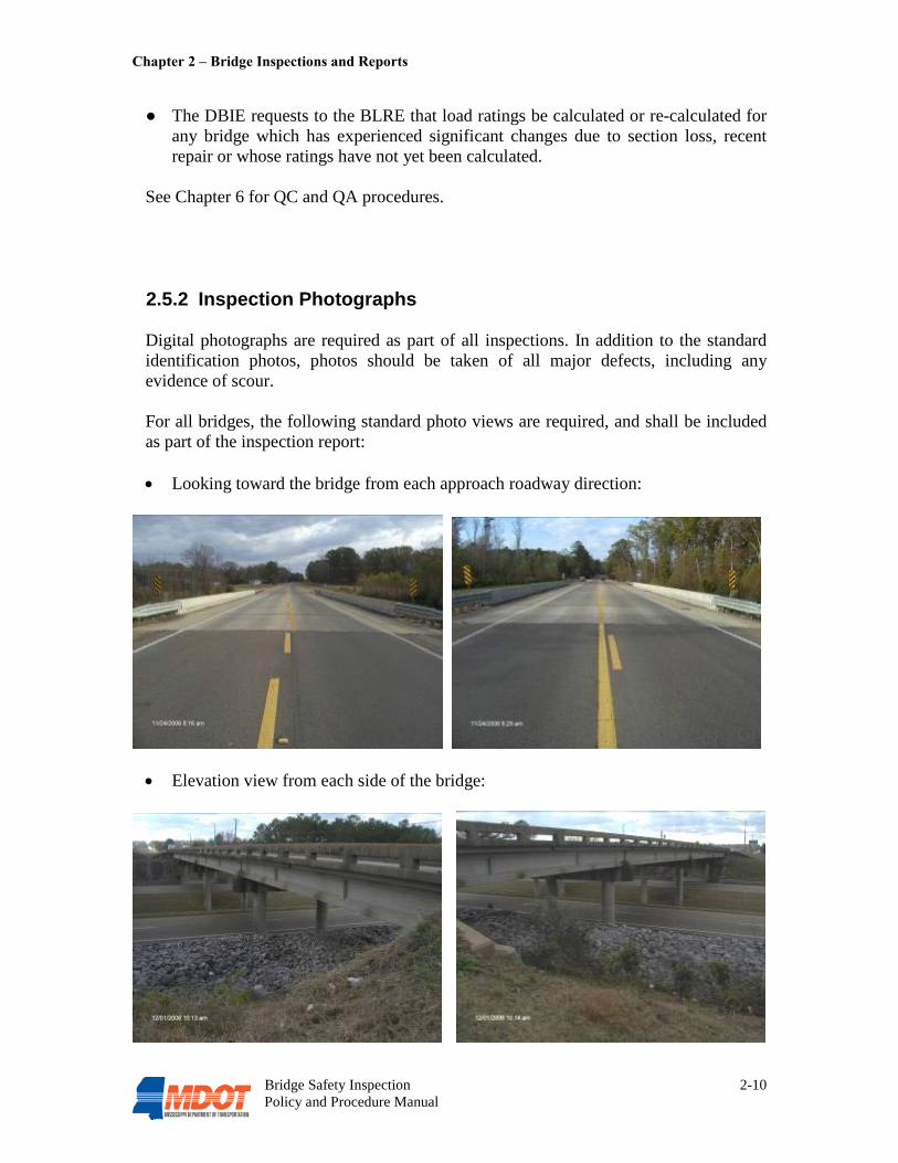
● The DBIE requests to the BLRE that load ratings be calculated or re-calculated for any bridge which has experienced significant changes due to section loss, recent repair or whose ratings have not yet been calculated.
See Chapter 6 for QC and QA procedures.
2.5.2 Inspection Photographs
Digital photographs are required as part of all inspections. In addition to the standard identification photos, photos should be taken of all major defects, including any evidence of scour. For all bridges, the following standard photo views are required, and shall be included as part of the inspection report: • Looking toward the bridge from each approach roadway direction:
• Elevation view from each side of the bridge:

Chapter 2 – Bridge Inspections and Reports
Bridge Safety Inspection 2-11 Policy and Procedure Manual
• Hydraulic Structures – up stream & down stream through bridge showing stream banks:
• Overpasses – Road beneath looking under bridge in direction of traffic:
For all culverts, the following standard photo views are required, and shall be included as part of the inspection report: • Looking toward the culvert from each approach roadway direction:
Chapter 2 – Bridge Inspections and Reports
Bridge Safety Inspection 2-12 Policy and Procedure Manual
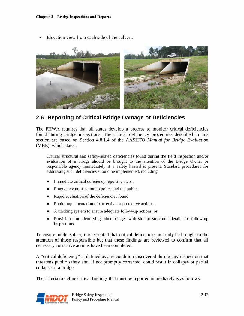
• Elevation view from each side of the culvert:
2.6 Reporting of Critical Bridge Damage or Deficiencies The FHWA requires that all states develop a process to monitor critical deficiencies found during bridge inspections. The critical deficiency procedures described in this section are based on Section 4.8.1.4 of the AASHTO Manual for Bridge Evaluation (MBE), which states:
Critical structural and safety-related deficiencies found during the field inspection and/or evaluation of a bridge should be brought to the attention of the Bridge Owner or responsible agency immediately if a safety hazard is present. Standard procedures for addressing such deficiencies should be implemented, including: ● Immediate critical deficiency reporting steps,
● Emergency notification to police and the public,
● Rapid evaluation of the deficiencies found,
● Rapid implementation of corrective or protective actions,
● A tracking system to ensure adequate follow-up actions, or
● Provisions for identifying other bridges with similar structural details for follow-up inspections.
To ensure public safety, it is essential that critical deficiencies not only be brought to the attention of those responsible but that these findings are reviewed to confirm that all necessary corrective actions have been completed. A “critical deficiency” is defined as any condition discovered during any inspection that threatens public safety and, if not promptly corrected, could result in collapse or partial collapse of a bridge. The criteria to define critical findings that must be reported immediately is as follows:

Chapter 2 – Bridge Inspections and Reports
Bridge Safety Inspection 2-13 Policy and Procedure Manual
● Bridges with recommendations for immediate action on any FCM.
● Bridges with recommendations for immediate correction of scour or hydraulic problems.
● Bridges with NBI condition ratings of 2 or less for the Superstructure, Substructure, or NBI appraisal ratings of 2 or less for waterway adequacy. NOTE: If temporary repairs are in place (Item 103 = T), then a Superstructure or Substructure condition rating may be a 2 or less and it WOULD NOT be considered a critical finding. This would only be in effect when the temporary repairs have restored the structural capacity of the structure such that the structure is safe for the traveling public.
● Bridges with recommendations for immediate work to prevent substantial reduction in safe load capacity.
A “hazardous deficiency” is defined as any condition found during any bridge inspection that may be hazardous to the public safety, but IS NOT expected to lead to collapse or partial collapse of the bridge. Examples of hazardous deficiencies include but are not limited to:
● Loose concrete hanging from an overpass as a result of over height damage.
● Ponding of water on the roadway surface as a result of plugged drain holes.
● Significant bridge rail or guardrail damage.
● Loose or broken joint armor. 2.6.1 Critical Deficiency Process
The following guidelines outline and describe the procedures to be followed if a critical deficiency is observed during a bridge inspection. These guidelines are divided into three parts; Responsibilities of the BITC, Responsibilities of the DBIE, and Responsibilities of the BIPM/Bridge Division. Part 1-Responsibilities of the BITC: Upon discovery of a critical deficiency, the BITC is responsible for the following: 1. Emergency Bridge Closure: If the observed condition is severe enough to warrant
immediate closure of the bridge (or immediate restriction of traffic above or below the bridge), the BITC shall immediately take any actions necessary to ensure public safety.
2. Notification of the DBIE: Upon discovery of a critical deficiency, the BITC shall immediately notify the DBIE within 2 hours. The inspector should identify the bridge number, bridge location, and clearly and accurately describe the nature of the critical condition.
3. Inspection Report: In addition to prompt verbal notification, a Critical Deficiency Report (form BRD008) should be completed and submitted to the DBIE within 48
Chapter 2 – Bridge Inspections and Reports
Bridge Safety Inspection 2-14 Policy and Procedure Manual
hours of finding the critical deficiency. The form should accurately describe the findings and appropriate photographs, measurements, sketches should supplement the form.
Part 2-Responsibilities of the DBIE: Upon being notified of a critical deficiency, the DBIE is responsible for the following: 1. Rapid Evaluation: The DBIE is required to quickly assess the situation to confirm
or refute the finding, and to initiate necessary traffic restrictions to ensure public safety. Requests for assistance in evaluating a critical deficiency, or for development of repair plans, should be directed to the State Bridge Engineer.
2. Immediate Actions: If the DBIE confirms the finding is a critical deficiency, the DBIE will immediately notify the District Engineer, the State Bridge Engineer and the BIPM. The district shall be responsible for coordinating all necessary traffic control (such as load weight or size restrictions, lane or bridge closures, or detours) as well as law enforcement and public notifications of any traffic restrictions.
3. Submittal of Critical Deficiency Report: If confirmed that the finding is a critical deficiency, within 72 hours of finding the critical deficiency, the DBIE will distribute a copy of form BRD008 as follows:
• Deputy Executive Director/Chief Engineer • State Maintenance Engineer • District Engineer • Assistant District Engineer - Maintenance • State Bridge Engineer • Director of Law Enforcement Division • FHWA, Division Bridge Engineer
4. Rapid Implementation of Corrective Action: The DBIE is responsible for promptly scheduling repairs to the bridge. If determined by the BLRE that weight restrictions are required, the DBIE shall ensure the prompt posting of the weight restrictions.
5. Resolution of Deficient Status: After repairs have been completed, a revised copy of
form BRD008 describing the corrective action taken will be submitted to the BIPM. Part 3-Responsibilities of the BIPM/Bridge Division: 1. Provide Immediate Assistance: When requested by the District Engineer or the
DBIE, the BIPM/Bridge Division will provide assistance for the following:
• Evaluation of the critical deficiency. • Development of repair plans. • Determine necessary traffic restrictions (lane closure, bridge closure). • Determine load ratings and, if necessary, recommend weight restrictions.
2. Recording the Critical Deficiency: Upon receipt of form BRD008, the BIPM will enter the appropriate condition ratings, inventory and operating ratings, and the

Chapter 2 – Bridge Inspections and Reports
Bridge Safety Inspection 2-15 Policy and Procedure Manual
related posting ratings into the PONTIS database. Additionally, to provide an efficient means of tracking the resolution to the critical finding, a “smart flag” is created in the PONTIS database upon initiation of form BRD008.
3. Follow-up: The BIPM shall continuously monitor the situation as necessary until the critical deficiency has been resolved and a revised copy of form BRD008 has been received indicating that corrective action has been completed.
4. Documenting and Updating the Bridge Inventory: Upon receipt of the revised form BRD008, the bridge inventory will be updated to reflect the remedial measures taken to resolve the critical finding. All pertinent documentation related to the critical finding, type of corrective action taken, and resolution of the deficiency shall become a permanent entry into the bridge record.
5. Reporting of Critical Bridge Deficiency Status: The BIPM/State Bridge Engineer will submit to the FHWA Division Bridge Engineer a critical bridge deficiency status report every 3 months or as requested.
2.6.2 Hazardous Deficiency Process All hazardous deficiencies require immediate corrective action by the district, and are to be immediately reported to the District Engineer, the Assistant District Engineer – Maintenance, and the DBIE. The DBIE will report the hazardous deficiency within 72 hours of the finding by distributing a copy of form BRD009 to the District Engineer, State Maintenance Engineer, and State Bridge Engineer. After repairs have been completed, the DBIE will distribute a revised copy of form BRD009 describing the corrective action taken. Requests for assistance in evaluating a hazardous deficiency, or for development of repair plans, should be directed to the State Bridge Engineer, otherwise no subsequent documentation will be required by the BIPM/State Bridge Engineer. FHWA notification and follow-up for hazardous deficiencies shall be provided only upon request. 2.6.3 MDOT’s Comprehensive Emergency Transportation Response
Plan
The MDOT Comprehensive Emergency Transportation Response Plan (CETRP) identifies policies, responsibilities and procedures for the regulation and use of highways and highway facilities within the state of Mississippi during an emergency and outlines procedures for emergency inspection of damaged bridges and reporting guidelines. A copy of the CETRP is available from the MDOT website: http://www.gomdot.com/Home/EmergencyPreparedness/CETRP/Home.aspx
2.7 Bridge Inspection Reports
Chapter 2 – Bridge Inspections and Reports
Bridge Safety Inspection 2-16 Policy and Procedure Manual
All bridge inspection reports are prepared by the District Bridge Inspectors, signed by the BITC and submitted to the DBIE for review and approval. The bridge inspection reports are considered legal documents and the signature of the BITC or acting team leader certifies the accuracy and completeness of the report. The DBIE’s signature on the inspection report only signifies that the DBIE has reviewed the report, and does not signify corroboration of the accuracy and thoroughness of either the field inspection itself, the assessment of the structure’s condition by the BITC, or the description of the structure’s condition by the BITC on the inspection report.
2.7.1 Minimum Requirements
All bridge inspection reports, at a minimum, should meet the requirements of Section 4.7 of the AASHTO MBE, which states:
Inspection forms and reports prepared for field use should be organized in a
systematic manner and contain sketches and room for notes. The completed report should be clear and detailed to the extent that notes and sketches can be fully interpreted at a later date. Photographs should be taken in the field to illustrate defects and cross referenced in the forms and reports where the various defects are noted. Sketches and photographs should be used to supplement written notes concerning the location and physical characteristics of deficiencies. The use of simple elevation and section sketches of deteriorated members permits the drawing and dimensioning of defects clearly, without resorting to lengthy written notes.
The sources of all information contained in a report should be clearly evident, and the date of the inspection or other sources of data should be noted. A report should be made for each bridge inspection even though it may be only a Special Inspection.
All signs of distress and deterioration should be noted with sufficient accuracy so that future inspectors can readily make a comparison of condition. If conditions warrant, recommendations for repair and maintenance should be included.
Standardized abbreviations, legends and methodologies should be developed and used for systematic numbering of bridge components to facilitate note taking and produce uniform results which are easily understood by all inspection teams and office personnel. The use of photographs and sketches to define areas and extent of deterioration should be encouraged. Nomenclature used to describe bridge components should be consistent.
MDOT highway bridge terms and abbreviations are included in Appendix C.
2.7.2 Bridge Maintenance Report
As part of the routine bridge inspection procedure, the DBI should make note of any items which require routine maintenance such as clogged scuppers, damaged approach guardrails, potholes, or debris in the stream channel. All items requiring maintenance attention shall be submitted on Form BRD005, Bridge Maintenance Repair Request (See Appendix E), and submitted to the DBIE with the inspection report.

Bridge Safety Inspection 3-1 Policy and Procedure Manual
Chapter 3 Bridge Inspection File (Records) 3.1 Purpose of Bridge Records The bridge inspection file is an integral part of an effective bridge inspection and management system. The information in the bridge inspection file is kept current through Routine Inspections. As bridge inspection files are updated, the existing information is archived and retained to establish a history for each bridge. Each district shall maintain a complete, accurate, and up-to-date record for each bridge under their jurisdiction. These records are needed to: ● Establish an inventory of infrastructure assets.
● Document the condition and functionality of infrastructure, including the need and justification for bridge restrictions, for public safety.
● Identify improvement and maintenance needs for planning and programming.
● Document improvements and maintenance repairs performed.
● Meet documentation requirements for work performed using federal and state funding.
● Provide available information in a timely manner for safety inspections. All bridge records, at a minimum, should meet the requirements of Section 2.1 of the AASHTO MBE, which states the following: Bridge Owners should maintain a complete, accurate and current record of each bridge
under their jurisdiction. Complete information, in good usable form, is vital to the effective management of bridges. Furthermore, such information provides a record that may be important for repair, rehabilitation, or replacement.
A bridge record contains the cumulative information about an individual bridge. It should provide a full history of the structure, including details of any damage and all strengthening and repairs made to the bridge. The bridge record should report data on the capacity of the structure, including the computations substantiating reduced load limits, if applicable.
A bridge file describes all of the bridges under the jurisdiction of the Bridge Owner. It contains one bridge record for each bridge and other general information which applies to more than one bridge.
Information about a bridge may be subdivided into three categories: inventory data which is normally not subject to change; condition data which is updated by field inspection; and data which is derived from the inventory and inspection data. In addition, each district shall maintain a master list of all bridges within their jurisdiction that have fracture-critical members, require underwater inspection, bridges determined to be scour critical, and/or warrant special attention because of their past maintenance requirements, design, location, or strategic importance. This information should be updated regularly and provided to the BIPM in the MDOT Bridge Division.

Chapter 3 – Bridge Inspection File (Records)
Bridge Safety Inspection 3-2 Policy and Procedure Manual
3.2 Components of Bridge Records The inspection information for individual bridges or set of bridges need not be located in a single central file. In fact, the wide variety of formats now in use for these records makes a “single file drawer” concept for file management impractical. For the purposes of this section, the generic term “Inspection File” is intended to encompass all of these records wherever they are physically stored. See Section 2.2 of the AASHTO MBE for a description of some of the components of good bridge records. The following components are required for every bridge record: 1. Map of the bridge site, which will be the project cover sheet for most bridges.
2. SI&A sheet from each inspection.
3. Inspection report/form BRD006 from each inspection including photographs and/or sketches of any deficiency.
4. Streambed profile taken along the length, and each side, of the bridge for hydraulic crossings. (If applicable)
5. Additional forms such as the Bridge Maintenance Repair Request (BRD005) or Critical Deficiency Report (BRD008).
6. Summary sheet of load rating calculations, including weight restriction recommendations, if applicable, and all supporting information.
7. Correspondence recommending application, modification, or removal of weight restrictions. (If applicable)
8. Scour Evaluation. (If applicable)
9. Scour Plan of Action (POA) for bridges determined to be scour critical. (If applicable)
10. Underwater inspection report(s). (If applicable)
11. Any other special inspection report(s). (If applicable)
12. Identification and inspection procedures for fracture-critical members and/or underwater elements. (If applicable) Note: Components 2, 3, 5 and 7 shall be filed in chronological order.

Chapter 3 – Bridge Inspection File (Records)
Bridge Safety Inspection 3-3 Policy and Procedure Manual
The following components will be stored on the Bridge Division intranet site due to physical file space constraints: 13. Digital photos of the bridge. See Section 2.5.2.
14. As-built plans.
15. Shop drawings.
16. Pile records.
17. Underwater inspection reports.
18. Repair plans (the 11117-1 and 11117-2 plans in the example below).
Figure 4 – MDOT Bridge Intranet Site

Bridge Safety Inspection 4-1 Policy and Procedure Manual
Chapter 4 Load Rating and Analysis Bridge load capacity analysis is required by federal regulation, the purpose of which is to assure the structure owner, and indirectly the highway user, that each bridge is safe for use by the motoring public. This chapter shall establish policy for the load ratings and posting of bridges under the MDOT jurisdiction as prescribed in Section 65-1 of the Mississippi Code of 1972, Annotated, the NBIS, and the AASHTO Manual for Bridge Evaluation (MBE). 4.1 MDOT Load Rating and Posting Policy Bridge load rating and bridge posting are performed in accordance with the requirements of Section 6 of the AASHTO MBE. The BLRE determines the safe load capacity rating for each bridge and is responsible for review and approval of all load ratings and their entry into the MDOT’s bridge inventory database. Qualifications for the BLRE are listed in Section 6.1.2.3. All load rating calculations are to be performed by a licensed professional engineer in the Bridge Management, Ratings & Inventory Section (See Section 1.3.4.2) and will be checked by a second professional engineer for accuracy, correctness, and completeness. Occasionally, a consultant may be utilized to perform load rating calculations. All consultant qualifications and procedures are to be in compliance with the NBIS and will be outlined in an Engineering Services Contract and Scope of Work. For each load rating analysis, a summary sheet, full documentation of the load rating computations, and any supporting information shall be provided and maintained in the bridge record for the life of the structure. The geometry and dimensions of the elements being load rated are generally obtained from the “as-built” construction plans; occasionally field measurements are required to accurately model deterioration or section loss of an element. The governing strength limit of a structural element can be flexural moment, shear stresses, axial stresses, or serviceability limits. In general, safe load capacity limit is governed by a girder, stringer, or floorbeam.
4.1.1 Criteria for Load Rating
Newly designed bridges will have an initial load rating analysis to determine the inventory and operating ratings upon finalization of the design plans. As such, the load ratings are available, as well as all other NBI required items, to be entered into the bridge inventory upon acceptance of the bridge to the MDOT maintenance jurisdiction. Bridge decks or substructures receive a load rating, at the discretion of the BLRE, only when deterioration or physical damage exists. Newly designed bridges do not receive a load rating by the bridge designer; this is done by the Bridge Management, Ratings & Inventory Section.

Chapter 4 – Load Rating and Analysis
Bridge Safety Inspection 4-2 Policy and Procedure Manual
Existing bridges undergoing modification(s) to their structure that differs significantly from its original design or that could alter the loading conditions being applied to their structure may be reason to perform an updated load rating analysis. Deterioration of any bridge elements may be reason to perform an updated load rating analysis. The decision to perform an updated load rating is at the discretion of the BLRE. Any subsequent change in the inventory and/or operating ratings are updated into the bridge database by the BLRE no later than 30 days from notification that the modifications have been completed, although generally this is done within 7 days of notification. Additionally, the updated load ratings and any identified critical members will be made a permanent entry into the bridge record. On occasion, a structure may be transferred from a local jurisdiction to state jurisdiction and there will be no plans as to how it was built; for these structures, a rating based on engineering judgment by a qualified engineer familiar with the bridge may be appropriate. A bridge rating based upon engineering judgment should consider, but it not limited to, the following factors: ● Condition of the load carrying components
● Material properties of members
● Redundancy of load path
● Traffic characteristics
● Performance of bridge under current traffic
● Past, current, or proposed bridge restrictions If the DBIE, BITC, or any other district personnel is of the opinion that a structure’s load capacity has changed due to damage or deterioration, a detailed description, drawings with dimensions, and photographs (if necessary for clarity) shall be submitted to the State Bridge Engineer, who will evaluate and possibly adjust the load capacity rating of the structure in the bridge inventory.
4.1.1.1 Loads
Bridge load rating analysis should generally include only those dead loads that the bridge currently carries. Dead loads used are to be fully documented in the load rating computations. Live load vehicles used for load rating are the AASHTO HS20 truck for inventory and operating ratings, and four state legal load trucks for posting restrictions (See Appendix H).
4.1.1.2 Impact Factors
The impact factor and distribution of live loads shall be determined in accordance with the AASHTO Standard Specifications for Highway Bridges and any case

Chapter 4 – Load Rating and Analysis
Bridge Safety Inspection 4-3 Policy and Procedure Manual
requiring adjustment to impact factors or a refined method of analysis shall be fully documented in the load rating computations approved by the BLRE. 4.1.1.3 Methods Load rating methods are Load Factor Rating (LFR) or Load and Resistance Factor Rating (LRFR) analysis for steel and concrete structures, and Allowable Stress Design (ASD) or LRFR analysis for timber components. MDOT will adhere to the FHWA policy memorandum dated October 30, 2006 to determine which load rating method is appropriate for each structure. 4.1.1.4 Software
The Bridge Management, Ratings & Inventory Section uses the AASHTO BRIDGEWare program Virtis to perform load ratings. As the successor to the Bridge Analysis and Rating Systems (BARS), Virtis can import existing BARS files.
4.1.2 Criteria for Posting or Closing
Size and weight restrictions on vehicles are sometimes necessary to ensure the safety of the traveling public and to protect the bridge infrastructure. Restrictions on bridges must be prudently established to maintain an adequate level of safety without impeding the general flow of traffic and emergency vehicles. Weight restrictions may be based on the condition of the bridge or upon traffic conditions. In addition, vertical clearance restrictions may be necessary. It is the responsibility of the DBIE to ensure that proper bridge restriction signs are installed and maintained. When bridge restriction signs are erected, removed or modified, the district shall provide written notification to the BLRE or BIPM as prescribed in section 4.1.3. The district bridge inspectors are to verify the existence and condition of bridge restriction signing during each inspection. Any signing deficiencies shall be noted in the inspection report and brought to the attention of the DBIE.
4.1.2.1 Statues and Regulations Regarding Bridge Restrictions
The below listed statutes and regulations regarding bridge restrictions apply to all bridges owned and maintained by the MDOT: ● National Bridge Inspection Standards (NBIS), § 650.313 (c)
Requires that bridges are to be load rated and if the state legal loads exceed the loads allowed under the operating rating, the bridge must be posted for a restriction. (See section 1.2.1 and Appendix B)

Chapter 4 – Load Rating and Analysis
Bridge Safety Inspection 4-4 Policy and Procedure Manual
● Mississippi Code of 1972, § 65-1-45 Weight limitation on highways and bridges – in part, this section empowers the state highway commission to restrict or prohibit the use of any state highway or bridge or to reduce the allowable weight permitted when such highways or bridges have been weakened due to any cause. (See section 1.2.2)
4.1.2.2 Bridge Posting Evaluation Each state maintained bridge shall be evaluated by the BLRE for its ability to safely carry each of the bridge posting vehicles illustrated in Appendix H. Any bridge that cannot carry the posting vehicles at its safe load capacity (100% of its operating rating) must be posted for the appropriate posting vehicle(s) in accordance with the AASHTO MBE. The BLRE shall determine the safe loading capacity for each of the bridge posting vehicles at the controlling section/member of the bridge for the various load effects of flexural moment, shear stresses, axial stresses, and serviceability limits. For most common steel or concrete bridges, the safe loading capacity is calculated using computer software, as identified in section 4.1.1.4. On occasion, due to lack of design plans or other pertinent information, engineering judgment must be applied in determining the safe loading capacity. As such, weight restrictions may be recommended based solely on sound engineering judgment. When establishing a weight restriction based on engineering judgment, a 5 ton increment for the posting vehicle(s) and 1 ton increment for single or tandem axles will be used.
If it is determined that the structure’s safe loading capacity has been significantly reduced, the BLRE or BIPM will advise the Assistant District Engineer-Maintenance that the posting signs shall be mounted with two 12" x 12" red flags. If for any reason any bridge structural elements are not capable of carrying a minimum gross live load weight of 3 tons, the bridge shall be physically closed in accordance with the Mississippi Code of 1972 and Sections 6A.8.1 & 6A.8.4 of the AASHTO MBE. Should any improvements be made to a structure that could increase the safe loading capacity, the district shall advise the BLRE in order to re-evaluate the bridge’s capability of carrying the posting vehicles and adjust the weight restrictions and load ratings accordingly. Each DBI, BITC, and DBIE shall be acutely cognizant of the condition of all state maintained bridges under their jurisdiction. Should any condition or appraisal reveal serious deterioration or physical damage resulting in the safe loading capacity being compromised, the district shall immediately take the appropriate action to mitigate the problem and safeguard the traveling public. (See section 2.6). Weight restrictions imposed upon the bridge shall be entered into the inventory by the BLRE or BIPM within a period of 7 days from the date of notification by the district that posting sign(s) have been installed. Additionally, a permanent entry into the bridge record shall include the following:

Chapter 4 – Load Rating and Analysis
Bridge Safety Inspection 4-5 Policy and Procedure Manual
• A summary sheet listing the inventory and operating ratings for each posting vehicle and the AASHTO HS20 truck. This summary sheet shall identify the location of the controlling member/section and shall indicate the recommended posting level.
• All supporting information, assumptions, and decisions.
• All assumptions and/or decisions based on engineering judgment.
4.1.3 Procedures for Application, Modification, or Removal of Weight Restrictions
Application, modification, or removal of weight restrictions on bridges requires authorization of the MTC and approval of the Executive Director of the MDOT. Procedures for this process are as follows:
1. The BLRE or BIPM notifies the Assistant District Engineer – Maintenance that due
to current structural conditions, the subject bridge(s) requires application, increase, decrease or removal of weight restrictions.
2. In the event weight restrictions are being applied, increased or decreased, the Assistant District Engineer – Maintenance orders the specific posting signs from the Jackson Sign Shop.
3. The State Bridge Engineer contacts the State Maintenance Engineer with specific information regarding the bridge(s) location and weight restrictions.
4. The State Bridge Engineer sends a letter to the Executive Director for his approval of the action and distributes a copy to the District Engineer, Director of Law Enforcement, and the State Maintenance Engineer.
5. The State Maintenance Engineer requests a MTC agenda item for the next meeting asking the MTC to ratify the actions of the Executive Director in the proposed action.
6. The Assistant District Engineer – Maintenance notifies the BLRE when the appropriate signs have been placed or removed as required.
7. The BLRE changes the bridge database information to reflect the new posting conditions.
8. A copy of the approval letter from the Executive Director is placed in the bridge file.
For emergency situations, the district is to take actions it deems necessary for public safety. The formal posting authorization process should be completed shortly thereafter. When a bridge is closed to traffic and undue inconvenience to the traveling public results there from, or the lack of necessary repair constitutes a hazard or danger to the structure, the Executive Director of the MDOT may, at his discretion, declare an emergency exists and emergency procedures shall be instituted for repair of the bridge.

Chapter 4 – Load Rating and Analysis
Bridge Safety Inspection 4-6 Policy and Procedure Manual
4.2 Hauling Permits This section to be added at a later date.

Bridge Safety Inspection 5-1 Policy and Procedure Manual
Chapter 5 National Bridge Inventory (NBI) 5.1 Bridge Inventory Data Each state agency must prepare and maintain an inventory of all bridges subject to the NBIS. Certain Structure Inventory and Appraisal (SI&A) data must be collected and retained by the state. This data is reported to the FHWA as requested, using established procedures as outlined in the FHWA report, Recording and Coding Guide for the Structure Inventory and Appraisal of the Nation’s Bridges (NBI Coding Guide). The Bridge Management, Ratings & Inventory Section is responsible for the maintenance of the MDOT Bridge Inventory Data. See Section 1.3.4.2 for the responsibilities of the BIPM. The coding of inventory and inspection items is according to the NBI Coding Guide. It is important to note that the items listed in the NBI Coding Guide apply to both the field and office personnel responsible for bridge inspections. The bridge inspector is not required to obtain the data for all the items during every inspection of a bridge. Once a bridge has been inventoried, the majority of the NBI items should remain unchanged. The inspector should spot check to see if inventoried items are consistent with findings from the bridge site.
5.1.1 Inventory Items Inventory items pertain to a bridge’s characteristics. For the most part, these items are permanent characteristics, which only change when the bridge is altered in some way, such as reconstruction or load restriction. Inventory items include the following NBI items: ● Identification – Identifies the structure using location codes and descriptions.
● Structure Type and Material – Categorizes the structure based on the material, design and construction, the number of spans, and wearing surface.
● Age and Service – Information showing when the structure was constructed or reconstructed, features the structure carries and crosses, and traffic information.
● Geometric Data – Includes pertinent structural dimensions.
● Design Load – The live load for which the structure was designed.
● Navigation Data – Identifies the existence of navigation control, pier protection, and waterway clearance measurements.
● Classification – Classification of the structure and the facility carried by the structure are identified.
● Required Inspections – Includes designated inspection frequency and critical features requiring special inspections or special emphasis during inspection.

Chapter 5 – National Bridge Inventory (NBI)
Bridge Safety Inspection 5-2 Policy and Procedure Manual
All inventory items are explained in the NBI Coding Guide. Although inventory items are usually provided from previous reports, the inspector must be able to verify and update the inventory data as needed. 5.1.2 Condition Items
The MDOT collects bridge condition data using NBI Coding Guide criteria and element level criteria. The MDOT also collects bridge data using AASHTO Commonly Recognized (CoRe) Elements plus additional state-specific CoRe Elements. A complete list of the AASHTO CoRe Elements and MDOT state-specific CoRe Elements is included in Appendix F. Condition ratings are determined by inspectors in the field and describe the actual, in-place condition of various bridge components. Evaluation is for the materials-related, physical condition of the deck, superstructure, and substructure. The condition evaluation of culverts, channels and channel protection is also included. Condition codes are properly used when they provide an overall characterization of the general condition of the entire component being rated. Conversely, they are improperly used if they attempt to describe localized or nominally occurring instances of deterioration or disrepair. Correct assignment of a condition code must consider both the severity of the deterioration or disrepair and the extent to which it is widespread throughout the component being rated. The load-carrying capacity will not be used in evaluating condition items. The fact that a bridge was designed for less than current legal loads and may be posted shall have no influence upon condition ratings. The following general condition ratings shall be used as a guide in evaluating Items 58 (deck), 59 (superstructure), and 60 (substructure): Code Description N Not Applicable 9 Excellent Condition 8 Very Good Condition – no problems noted. 7 Good Condition – some minor problems. 6 Satisfactory Condition – structural elements show some minor
deterioration. 5 Fair Condition – all primary structural elements are sound but may have
minor section loss, cracking, spalling or scour. 4 Poor Condition – advanced section loss, deterioration, spalling or scour.
3 Serious Condition – loss of section, deterioration, spalling or scour have seriously affected primary structural components. Local failures are possible. Fatigue cracks in steel or shear cracks in concrete may be present.

Chapter 5 – National Bridge Inventory (NBI)
Bridge Safety Inspection 5-3 Policy and Procedure Manual
2 Critical Condition – advanced deterioration of primary structural elements. Fatigue cracks in steel or shear cracks in concrete may be present or scour may have removed substructure support. Unless closely monitored it may be necessary to close the bridge until corrective action is taken.
1 “Imminent” Failure Condition – major deterioration or section loss present in critical structural components or obvious vertical or horizontal movement affecting structure stability. Bridge is closed to traffic but corrective action may put back in light service.
0 Failed Condition – out of service – beyond corrective action.
5.1.3 Appraisal Items
Appraisal items are an evaluation of a bridge component condition in comparison to current standards. Appraisal items are used to evaluate the structure based on the level of service it provides on the highway system. Depending on the item being evaluated, the value may be determined by the DBI, calculated by Pontis software (see Section 5.1.4), or calculated by Bridge Management, Ratings, and Inventory Section personnel. Appraisal rating items include the following NBI items: ● Structural Evaluation – Overall condition of the structure based on all major
deficiencies, and its ability to carry loads.
● Deck Geometry – Evaluates the curb-to-curb bridge roadway width and the minimum vertical clearance over the bridge roadway.
● Under-clearances, Vertical and Horizontal – The vertical and horizontal under-clearances from the through roadway under the structure to the superstructure or substructure units.
● Waterway Adequacy – Appraises waterway opening with respect to passage of flow under the bridge.
● Approach Roadway Alignment – Compares the alignment of the bridge approaches to the general highway alignment of the section of highway that the structure is on.
● Traffic Safety Features – Record information on bridge railings, transitions, approach guardrail and approach guardrail ends, and evaluates their adequacy compared to current standards.
● Scour Critical Bridges – Identifies the current status of the bridge regarding its vulnerability to scour.
● Load Rating and Posting – Identifies the load-carrying capacity of the bridge and the current posting status.
5.1.4 Pontis
The MDOT Bridge Division uses the AASHTO BRIDGEWare program Pontis, a software application developed to assist in managing highway bridges and other structures. Pontis stores bridge inspection and inventory data based on FHWA and

Chapter 5 – National Bridge Inventory (NBI)
Bridge Safety Inspection 5-4 Policy and Procedure Manual
NBIS coding guidelines. In addition, the system stores condition and appraisal data for each of a bridge's structural elements.
5.2 FHWA Reporting Guidelines
5.2.1 Structure Inventory and Appraisal
The NBI Coding Guide is used for establishing the bridge inventory and the overall condition of the deck, superstructure, substructure, and channel. The data must be reported using FHWA established procedures as outlined in the NBI Coding Guide. It is not an inspection guide. The state is responsible for having the capability to obtain, store, and report certain information about bridges, for collection by FHWA as requested. The NBI sheet is a tabulation of information that must be submitted for each individual structure. Any requests by the FHWA for submittals of NBI data will be based on the definitions, explanations, and codes supplied in this manual, its supplements, and the NBI Coding Guide with interim changes or the most recent version. It is important to note that the NBI sheet is not an inspection form. Rather, it is a summary sheet of bridge data required by the FHWA to effectively monitor and manage the National Bridge Inspection Program and the Highway Bridge Replacement and Repair Program (HBRRP). 5.2.2 Data Entry Requirements All NBI data shall be reviewed by the DBIE prior to entry into the bridge inventory database. The BITC is responsible for updating the bridge inventory data. National Bridge Inventory data for routine, in-depth, fracture-critical, underwater, damage and special inspections shall be entered into the state inventory within 90 days of the date of inspection. For existing bridge modifications that alter previously recorded data and for new bridges, the NBI data shall be entered into the state inventory within 90 days after the completion of the work. For changes in load restriction or closure status, the NBI data shall be entered into the state inventory within 90 days after the change in status of the structure.
5.3 Structure Identification
5.3.1 Labeling Structures
The BITC or DBI will stencil the Bridge Number on the outside face of the outside stringer under the right traffic lane at the rear abutment approximately six feet from the end of the stringer. The Bridge Number will also be stenciled on the opposite side at the forward end of the bridge.

Chapter 5 – National Bridge Inventory (NBI)
Bridge Safety Inspection 5-5 Policy and Procedure Manual
The Bridge Number will be stenciled on the inside face of the right traffic rail within three feet of the rail end, visually convenient for identification purposes. On a state maintained underpass, the Bridge Number will be placed on the southern or western abutment, or column, approximately six feet high or higher, where it does not face the traffic. On box bridges the Bridge Number will be placed on the vertical face of the wing wall on the right end of the box near the rear abutment for the right traffic lane and on the left end of the box near the forward abutment for the left traffic lane.
5.3.2 Structure Keys
The Structure Key is a five-digit integer number that is used to uniquely identify each structure, assigned by the BIPM. The Structure Key will be placed on each sheet of the structural contract plans. 5.3.3 Bridge Number/Mile Post Each bridge shall be assigned a bridge number by the BIPM or BITC that is equal to the distance in miles and tenths from the southern or western terminus of the route carried by the bridge to the southern or western end of the bridge. As such, the bridge number is also referred to as the mile post for that bridge. The terminus of a route that crosses a state line will be considered to be the point of intersection between the route and the state line. 5.3.4 Structure Number As prescribed in the NBI Coding Guide, each bridge shall be assigned an official structure number that is unique to each bridge in the MDOT inventory. Additionally, once established, the structure number should never change for the life of the bridge. The method MDOT uses in assigning a structure number, which is NBI Item 8 containing 15 digits, is comprised of NBI Item 5 (segments B, C, D, and E), route number, county code, and the mile post for the route. See the following illustration:
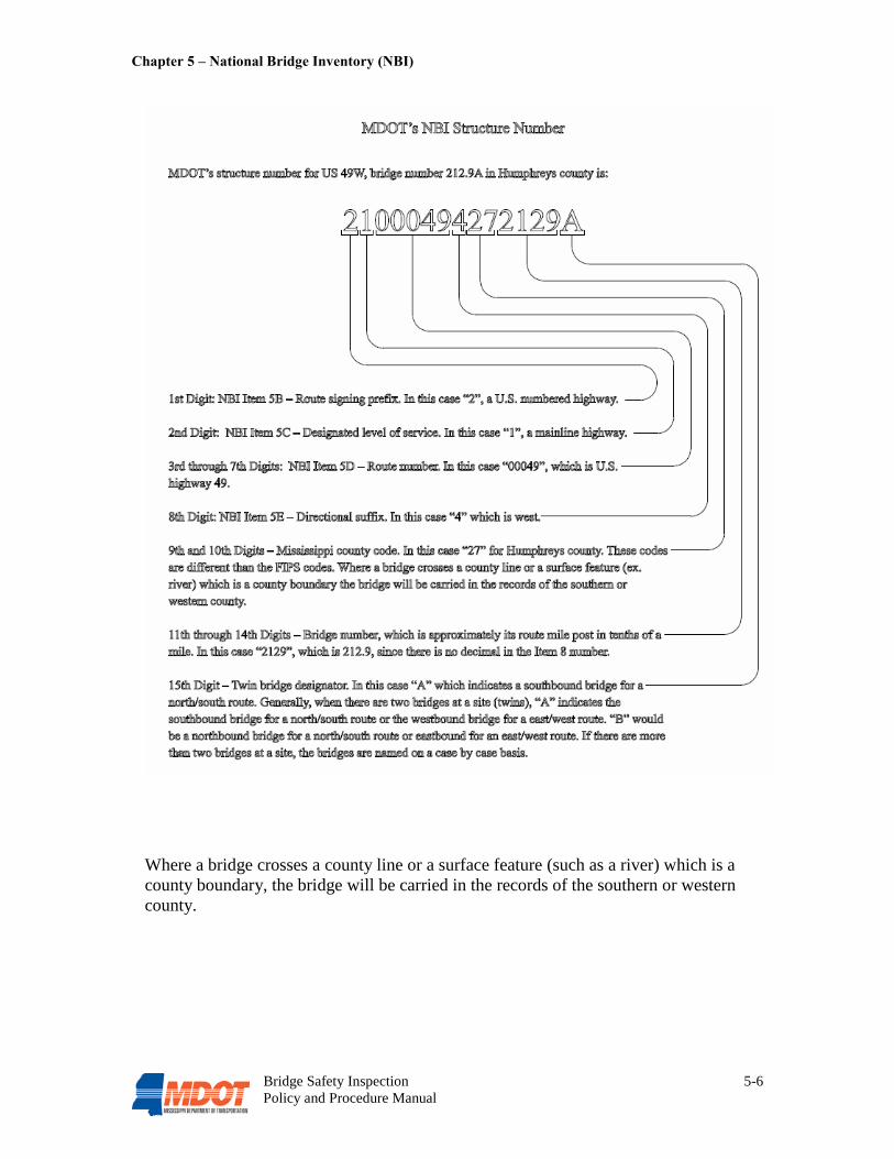
Chapter 5 – National Bridge Inventory (NBI)
Bridge Safety Inspection 5-6 Policy and Procedure Manual
Where a bridge crosses a county line or a surface feature (such as a river) which is a county boundary, the bridge will be carried in the records of the southern or western county.
Bridge Safety Inspection 6-1 Policy and Procedure Manual
Chapter 6 Quality Control and Quality Assurance In order to assure a high degree of quality, accuracy and consistency in the state’s bridge inspection program, and to protect the safety and investment of the public, it is necessary to implement and incorporate comprehensive QC and QA procedures. Observations and assessments made during the course of an inspection must be uniform on a statewide basis. Inspection information must be accurate and consistent in order to correctly determine the need for any maintenance or repairs, and to establish replacement priority if required. The MDOT Bridge Division is responsible for oversight of these QC and QA procedures, which are to be implemented by each district. 6.1 Quality Control Procedures Quality Control includes checks and procedures that are intended to maintain the quality of a bridge inspection and load rating at or above a specified level.
6.1.1 Organization and Staffing
An effective QC program begins with assuring that an adequate, properly equipped and qualified staff is in place to address the primary functions of a bridge inspection program.
6.1.1.1 Bridge Management, Ratings & Inventory Section See Section 1.3.4.2 for a description of the roles and responsibilities of the Bridge Management, Ratings & Inventory Section.
6.1.1.1.1 Bridge Inspection Program Manager
Of paramount importance will be the BIPM’s ability to provide good judgment in determining the urgency of problems and to implement and prioritize the necessary remedial actions to provide for the safety of the public. This individual will need a general understanding of the Bridge Division’s role and the information required in maintaining the state’s bridge inventory and bridge management system. Qualifications Required Refer to § 650.309 of the NBIS. At a minimum, the BIPM must have the following qualifications: ● Be a registered professional engineer with five years of experience in bridge
design and bridge inspection; and
● Successfully complete the 10 day NHI training course, “Safety Inspection of In-Service Bridges” or an equivalent FHWA approved course.

Chapter 6 – Quality Control and Quality Assurance
Bridge Safety Inspection 6-2 Policy and Procedure Manual
Quality Control Roles and Responsibilities In addition to the responsibilities listed in Section 1.3.4.2, the BIPM also has the following responsibilities, as related to QC. These responsibilities may be conducted by the BIPM or by others under the supervision of the BIPM: ● Ensure compliance of inspection data with the NBIS and the policies and
procedures of the FHWA and MDOT.
● Ensure that the defined QC procedures are performed by the DBIE in each district.
● Maintain a roster and organizational chart of staff addressing these primary functions, and ensure that all districts have the proper staff for the bridges assigned to them.
● Ensure that all bridge inspection staff meets NBIS and MDOT requirements for certification, training, and experience.
● Review, validate, and approve all load ratings when the calculated results indicate the need for a change in posting/closing condition.
● Check, review, and validate the MDOT’s bridge inventory for accuracy and completeness. This shall consist of selecting a minimum of 10 bridges at random and performing ‘spot checks’ of inventory data, performed on a quarterly basis.
● Send quarterly inspection schedule status reports to each district. Each report shall show bridges in their respective districts past due for inspection, due for inspection within 30 days, due for inspection within 60 days and due for inspection within 90 days.
6.1.1.1.2 Bridge Load Rating Engineer
Qualifications Required At a minimum, the BLRE must have the following qualifications: ● Be a registered professional engineer; and
● Have five years bridge experience, preferably in bridge design; and
● Successfully complete the 10 day NHI training course, “Safety Inspection of In-Service Bridges” or an equivalent FHWA approved course.
Quality Control Roles and Responsibilities The BLRE shall assist the BIPM in the QC roles and responsibilities listed in Section 6.1.1.1.1.

Chapter 6 – Quality Control and Quality Assurance
Bridge Safety Inspection 6-3 Policy and Procedure Manual
6.1.1.2 MDOT Districts
See Section 1.3.5.2 for a description of the roles and responsibilities of the district bridge safety inspection personnel.
6.1.1.2.1 District Bridge Inspection Engineer
Qualifications Required ● Be a registered professional engineer with five years of experience in bridge
design, bridge inspection, bridge construction, or bridge maintenance; and
● Successfully complete the 10 day NHI training course, “Safety Inspection of In-Service Bridges” or an equivalent FHWA approved course.
Quality Control Roles and Responsibilities In addition to the responsibilities listed in Section 1.3.5.2, the DBIE also has the following responsibilities, as related to QC: • Review all inspection reports for bridges in his/her district prepared by district
bridge inspection personnel for compliance with the NBIS and FHWA and MDOT requirements before the data is entered into the PONTIS system. The review shall consist of the following:
- Overall review of the inspection report to check that the correct form has
been used, that the correct bridge is identified and that all required information has been entered.
- Review that all information has been correctly entered in accordance with the FHWA Coding Guide. This review will include but not be limited to a check that proper coding conventions, format, significant digits and correct units have been used.
- Check that the condition ratings for NBI Items 58 through 62 are appropriate and consistent with the context of the report.
- Check that there is adequate documentation for items with condition ratings of 6 or lower.
- Check that all photographs and/or sketches have been properly cross-referenced to the inspection report.
- Check that there is consistency of information between the current inspection report and previous inspection reports, as well as the latest UWI report, if applicable.
- Check for proper documentation for any changes from the previous NBI data, and review all items in the NBI after data entry to check that they have been properly and correctly entered.

Chapter 6 – Quality Control and Quality Assurance
Bridge Safety Inspection 6-4 Policy and Procedure Manual
- For Initial Inspections, check the inventory data on the SI&A against the construction plans to ensure that the data is consistent.
• The DBIE shall notify the BIPM within 30 days of any inspection findings resulting in a condition rating of 4 or less for deck, superstructure, or substructure.
• Monitor the inspection schedules to ensure that there are no overdue inspections.
On a quarterly basis, the DBIE should:
● Review scour critical list and subsequent POA to ascertain any change in status and/or the need for scour countermeasures; meet with first-level responders to ensure their responsibilities are understood.
● Review critical findings list and follow-up accordingly to ensure rapid implementation of corrective action being taken to resolve the deficiency.
● Check BRD005 forms for completeness and update records accordingly.
On a biannual basis, the DBIE should: ● Select a minimum of six bridges that were inspected in the previous two
quarters and perform site visits.
● Independently rate each bridge for condition and appraisal ratings using NBI Coding Manual.
● Compare results with previous inspection reports.
● Review field observations with BITC and inspectors.
● Review reference materials and inspection tools with BITC and inspectors.
● Review a minimum of 5 to 10 bridge files at random for completeness. On an annual basis, the DBIE should:
● Review posted bridge list and verify that each bridge has the correct signing in place, as recommended by the BLRE. Annually on or about January 31, the DBIE shall submit a list of all posted bridges in his/her district to the Bridge Management, Ratings and Inventory Section. This list shall include the location, type of weight restriction, and the date of the posting recommendation.
● Review fracture-critical bridge list.
● Review with the District Engineer and the BIPM the procedures to be used in the event of a bridge emergency for reporting and coordinating repairs.
● Review with the BIPM the procedures for selection of candidates for the bridge maintenance program and rehabilitation/replacement programs. Review accomplishments and identify concerns.

Chapter 6 – Quality Control and Quality Assurance
Bridge Safety Inspection 6-5 Policy and Procedure Manual
● Review how large discrepancies in bridge inspection condition/appraisal ratings or posting recommendations from the previous inspection are handled by the BITC.
● Document and follow-up on problems identified.
6.1.1.2.2 Bridge Inspection Team Coordinator
Qualifications Required At a minimum, the BITC must have the following qualifications: ● Be a registered professional engineer with two years of experience in bridge
design, bridge inspection, bridge construction, or bridge maintenance; and
● Successfully complete the 10 day NHI training course, “Safety Inspection of In-Service Bridges” or an equivalent FHWA approved course.
Quality Control Roles and Responsibilities ● Ensure that bridge inspections are performed safely in a consistent and
satisfactory manner.
● Ensure that inspection reports contain complete and appropriate information.
● Ensure that all types of bridge inspections are performed within the assigned inspection frequency.
Quarterly, the BITC should: ● Review files for 10% of the bridges inspected in the previous three months for
completeness and accuracy.
● Review posted bridge lists and review the bridge record for 10% of these bridges which were inspected within the previous quarter to see that the bridge record documentation is complete in accordance with the NBIS, the actual posting signs are in agreement with the weight restrictions recommended by the BLRE, and the rating is current with the latest inspection findings.
6.1.1.2.3 District Bridge Inspector
Qualifications Required At a minimum, all District Bridge Inspectors must have the following qualifications: ● Have a high school diploma; and
● Have two years of experience in construction or inspection of bridges; and
Chapter 6 – Quality Control and Quality Assurance
Bridge Safety Inspection 6-6 Policy and Procedure Manual
● Successfully complete the 5 day NHI training course, “Engineering Concepts for Bridge Inspectors” or an equivalent FHWA approved course; and
● Successfully complete the 10 day NHI training course, “Safety Inspection of In-Service Bridges” or an equivalent FHWA approved course.
In addition to the above minimum requirements, the DBI may qualify as an inspection team leader and serve in that capacity in the absence of the BITC, provided that one of the following two qualifications are met:
1) Have the qualifications specified for the BIPM or DBIE, or
2) Have ten years bridge inspection experience.
6.1.2 Annual Meeting with Bridge Inspection Staff An annual meeting of field inspection staff including the DBIE from each district, the BIPM, and the BLRE is recommended to ensure that the entire team is aware of the latest developments in bridge safety inspection. This meeting shall be held at the MDOT headquarters. Additional meetings should be considered if significant issues or concerns arise. The BIPM shall review comments and observations with each DBIE, and provide feedback for improvements. In addition, the BIPM shall review the qualifications and training needs for all of the district bridge inspection personnel. This review should be separate from the QA program’s district close-out meeting (see Section 6.2.2).
6.2 Quality Assurance Procedures Quality Assurance is an objective evaluation of a service (i.e., an inspection) to establish that a pre-described level of quality has been met. The purpose of QA is to evaluate the bridge safety inspection program effectiveness, uniformity, and compliance with federal and MDOT policies. These measurements are used to enhance or emphasize training needs and to address statewide bridge inspection anomalies.
6.2.1 BIPM Annual Review
The MDOT Bridge Division annual review performed by the BIPM shall be in conjunction with the FHWA annual review. The BIPM or his designee, along with another qualified individual from the Bridge Division shall independently re-inspect a total of twelve NBIS bridges annually. This is to consist of six bridges in each of two districts. The two districts inspected each year are to be rotated so that all districts are reviewed at least once every four years.
Chapter 6 – Quality Control and Quality Assurance
Bridge Safety Inspection 6-7 Policy and Procedure Manual
The bridges to be re-inspected are to be selected at random; however, the selected bridges typically should not require special equipment to inspect, have reasonable ADT and be of a reasonable size in order to minimize the cost of the re-inspection and the overall cost of the QA program. In addition, at least one of the selected bridges in each district should meet one or more of the following criteria:
● Posted for weight restrictions
● Scour critical
● Has had a critical finding
● Contains a fracture-critical member
● Has a condition rating of 5 or less on one or more of NBI items 58 (Deck), 59 (Superstructure), 60 (Substructure), 61 (Channel), or 62 (Culvert)
6.2.1.1 Field Inspections As part of the field inspections, the BIPM or his designee should:
● Verify and identify the structure
● Arrange for MOT if required
● Photograph the structure with a digital camera
● Verify bridge inventory data
● Verify safety features and posting signs
● Perform independent condition/appraisal ratings
● List and prioritize maintenance/repair needs and conduct a maintenance needs assessment
The ratings from the QA blind inspection are compared to the ratings from the original inspection. 6.2.1.2 Office Review
The BIPM should visit each district office as part of the annual review. Elements of the office review shall include the following: ● Evaluation of bridge safety inspection personnel qualifications
● Review of bridge records for the six bridges which have been selected
● Review bridge master lists
● Review the district bridge inspection procedures
Chapter 6 – Quality Control and Quality Assurance
Bridge Safety Inspection 6-8 Policy and Procedure Manual
● Review critical finding procedures In addition, for each of the six bridges selected for review, the BIPM shall verify that the following items are accurate and should correct any discrepancies: ● Inventory and inspection documentation in bridge records should match with data
in the bridge inventory
● Load rating analysis data in bridge records should match data in the bridge inventory
● Compliance with posting policy
● Verify that inspection forms have been completed
● Verify any maintenance items required
6.2.2 District Close-Out Meeting
The district close-out meeting is a forum to discuss the findings of the annual QA review. This is an opportunity to discuss findings from QA inspections with inspectors, discuss rating analyses, posting evaluations and other bridge inspection related issues. The meeting encourages communication between QA reviewers and inspectors and the results are used to emphasize training requirements, improve inspection techniques, and initiate needed changes to inspection and coding manuals and rating programs. An annual meeting shall be held at each district office being reviewed, and should include the BIPM, BLRE, District Engineer, DBIE, BITC, and all District Bridge Inspectors. 6.2.3 District Summary Report
A summary report should be prepared by the BIPM for each of the two districts being reviewed. The report should include a summary of the district close-out meeting, as well as results of the QA inspections and a discussion about the bridge inspection procedures and the maintenance needs assessment for each of the bridges reviewed. Recommendations and conclusions should be given regarding the district’s effort. 6.2.4 Disqualification
6.2.4.1 Out-of-Tolerance
The inspection condition ratings for NBI items 58-62 compiled during the BIPM Annual Review shall be compared to the ratings in the most recent district inspection report. These condition ratings are considered to be out-of-tolerance if they vary more than ±1 from the ratings compiled by the BIPM or his/her designee.
Chapter 6 – Quality Control and Quality Assurance
Bridge Safety Inspection 6-9 Policy and Procedure Manual
6.2.4.2 Reasons for Disqualification
Typical reasons for disqualification can be, but are not limited to, the following: ● Numerous items are found to be out-of-tolerance during the course of the review
● Lack of proper follow-up and notification of critical and/or hazardous findings
● Lack of follow-up for correcting load posting deficiencies
● Failure to correct findings from QC or QA reviews
● Recurring miscoded critical inventory items such as NBI items 29, 30, 36, 51, 53, 54, 55, 56, 92, 93, and 113
● Failure to submit completed inspection data and/or corrections in a timely manner
● Failure to complete soundings at each inspection
● Fraud, abuse, or falsification of information
● Failure to maintain orderly and complete bridge records
6.2.4.3 Disqualification Procedures When the annual review indicates that an individual continues to make the same or similar mistakes, omissions, etc., the MDOT Bridge Division shall implement disqualification procedures as follows: ● The individual will be placed on probation and reviewed again in six (6) months.
This review will be conducted by a team consisting of the BIPM, and a representative of the district.
● If the same or similar mistakes are found during this second review, the individual shall be given notification that they will be disqualified if these problems are not corrected and avoided in the future, and placed on a secondary probation period of three (3) months.
● If the same or similar problems are found during the third review, the individual will be notified that they are disqualified for a minimum of one year and will no longer be allowed to perform bridge safety inspections in the state until they have been re-qualified.
● A disqualified individual may be re-qualified to perform bridge safety inspections after the one-year period if:
1) The disqualified individual successfully completes the 3 day NHI training course, “Bridge Inspection Refresher Training” or an equivalent FHWA approved course; and
2) Undergoes a subsequent QA review by the BIPM to verify that the disqualification discrepancies have been resolved.

Chapter 6 – Quality Control and Quality Assurance
Bridge Safety Inspection 6-10 Policy and Procedure Manual
Upon approval by the MDOT Bridge Division, the individual shall be re-qualified.
The MDOT Bridge Division has the final authority to carry out the disqualification process. All personnel involved in bridge safety inspections must agree to these procedures before they will be allowed to perform any bridge safety inspections.
6.3 Training and Continuing Education As part of the QA process, some form of continuing education and training will be required for all personnel involved in bridge safety inspections. At a minimum, all bridge safety inspection personnel must successfully complete the NHI training course, “Bridge Inspection Refresher Training” or an equivalent FHWA approved course every three years. The MDOT offers several bridge inspection training courses as well as a bridge inspection certification program and refresher course for its bridge safety inspectors and supervisors. Theses courses are offered by the National Highway Institute (NHI) and are listed in Section 6.3.1.
6.3.1 National Highway Institute Established by Congress in 1970, the NHI is a part of the Office of Professional and Corporate Development within the FHWA. The NHI helps improve the performance of the transportation industry through training, and provides both classroom based and distance based learning. The goals of the NHI are to train the current and future transportation workforce, transfer knowledge quickly and effectively to and among transportation professionals, and to provide training that addresses the full life cycle of the highway transportation system. The following NHI courses are currently available to MDOT employees performing bridge safety inspections: ● Safety Inspection of In-Service Bridges
● Bridge Inspection Refresher Training
● Engineering Concepts for Bridge Inspectors
● Fracture Critical Inspection Techniques for Steel Bridges
● LRFD for Highway Bridge Superstructures - Steel and Concrete
● LRFD for Highway Bridge Substructures and Earth Retaining Structures
● Inspection and Maintenance of Ancillary Highway Structures
● Bridge Construction Inspection

Chapter 6 – Quality Control and Quality Assurance
Bridge Safety Inspection 6-11 Policy and Procedure Manual
● Underwater Bridge Inspection
● Load and Resistance Factor Rating for Highway Bridges
● Stream Stability and Scour at Highway Bridges for Bridge Inspectors A complete list of current course offerings is available at http://www.nhi.fhwa.dot.gov
6.3.2 Qualifications Database
The BIPM is to maintain a centralized database of all bridge inspection personnel experience and training, and is to ensure that proper experience and requirements are maintained by all bridge safety inspection staff. See the Bridge Inspector Training and Experience Record form in Appendix E.

APPENDIX A
References

A-1
The Manual for Bridge Evaluation (MBE), First Edition/2008 AASHTO (available for purchase) https://bookstore.transportation.org/item_details.aspx?ID=1343 Bridge Inspector’s Reference Manual (BIRM) U.S. Department of Transportation Publication No. FHWA NHI 03-002 http://www.nhi.fhwa.dot.gov/downloads/freebees/10/RM%20Reference%20Manual%202006.pdf Inspection of Fracture Critical Bridge Members U.S. Department of Transportation Report No. FHWA-IP-86-26 http://isddc.dot.gov/OLPFiles/FHWA/009349.pdf Culvert Inspection Manual U.S. Department of Transportation Report No. FHWA-IP-86-2 http://isddc.dot.gov/OLPFiles/FHWA/006625.pdf Underwater Inspection of Bridges U.S. Department of Transportation Report No. FHWA-DP-80-1 http://isddc.dot.gov/OLPFiles/FHWA/009738.pdf Underwater Evaluation and Repair of Bridge Components FHWA Demonstration Program 98 Participant Workbook FHWA-DP-98-1 http://isddc.dot.gov/OLPFiles/FHWA/009737.pdf Movable Bridge Inspection, Evaluation, and Maintenance Manual, 1st Edition AASHTO (available for purchase) https://bookstore.transportation.org/item_details.aspx?ID=76 Guidelines for the Installation, Inspection, Maintenance and Repair of Structural Supports for Highway Signs, Luminaries, and Traffic Signals Federal Highway Administration http://www.fhwa.dot.gov/bridge/signinspection.pdf Recording and Coding Guide for the Structure Inventory and Appraisal of the Nation’s Bridges (Coding Guide) U.S. Department of Transportation Report No. FHWA-PD-96-001 http://www.fhwa.dot.gov/BRIDGE/mtguide.pdf Errata Sheet, Recording and Coding Guide for the Structure Inventory and Appraisal of the Nation’s Bridges http://www.fhwa.dot.gov/bridge/errata.pdf Guide for Commonly Recognized Structural Elements and its 2002 Interim Revisions AASHTO (available for purchase) https://bookstore.transportation.org/item_details.aspx?ID=20

A-2
Manual on Uniform Traffic Control Devices (MUTCD) Federal Highway Administration http://mutcd.fhwa.dot.gov/pdfs/2003r1r2/pdf_index.htm Revisions to the National Bridge Inspection Standards (NBIS) FHWA Technical Advisory T5140.21, dated September 16, 1988 http://www.fhwa.dot.gov/legsregs/directives/techadvs/t514021.htm Evaluating Scour at Bridges, Fourth Edition Publication No. FHWA NHI 01-001 Hydraulic Engineering Circular No. 18 http://isddc.dot.gov/OLPFiles/FHWA/010590.pdf Evaluating Scour at Bridges FHWA Technical Advisory T5140.23, dated October 28, 1991 http://www.fhwa.dot.gov/legsregs/directives/techadvs/t514023.htm Mississippi Department of Transportation’s Comprehensive Emergency Transportation Response Plan (CETRP) Mississippi Department of Transportation http://www.gomdot.com/Home/EmergencyPreparedness/CETRP/Home.aspx National Cooperative Highway Research Program (NCHRP) Synthesis 375 Bridge Inspection Practices A Synthesis of Highway Practice Transportation Research Board of the National Academies http://onlinepubs.trb.org/onlinepubs/nchrp/nchrp_syn_375.pdf White Paper on Bridge Inspection and Rating ASCE/SEI-AASHTO Ad-hoc Group on Bridge Inspection, Rating, Rehabilitation, and Replacement http://content.seinstitute.org/files/pdf/Adhocwhitepaper_Final.pdf

APPENDIX B
NBIS Code of Federal Regulations (CFR) Chapter 23 Highways – Part 650
B-1
Subpart C
National Bridge Inspection Standards Source: 69 FR 74436, Dec. 14, 2004, unless otherwise noted. § 650.301 Purpose. This subpart sets the national standards for the proper safety inspection and evaluation of all highway bridges in accordance with 23 U.S.C. 151. § 650.303 Applicability. The National Bridge Inspection Standards (NBIS) in this subpart apply to all structures defined as highway bridges located on all public roads. § 650.305 Definitions. Terms used in this subpart are defined as follows: American Association of State Highway and Transportation Officials (AASHTO) Manual. “Manual for Condition Evaluation of Bridges,” second edition, published by the American Association of State Highway and Transportation Officials (incorporated by reference, see §650.317).
Bridge. A structure including supports erected over a depression or an obstruction, such as water, highway, or railway, and having a track or passageway for carrying traffic or other moving loads, and having an opening measured along the center of the roadway of more than 20 feet between undercopings of abutments or spring lines of arches, or extreme ends of openings for multiple boxes; it may also include multiple pipes, where the clear distance between openings is less than half of the smaller contiguous opening.
Bridge inspection experience. Active participation in bridge inspections in accordance with the NBIS, in either a field inspection, supervisory, or management role. A combination of bridge design, bridge maintenance, bridge construction and bridge inspection experience, with the predominant amount in bridge inspection, is acceptable.
Bridge inspection refresher training. The National Highway Institute “Bridge Inspection
Refresher Training Course”1 or other State, local, or federally developed instruction aimed to improve quality of inspections, introduce new techniques, and maintain the consistency of the inspection program.1 The National Highway Institute training may be found at the following URL: http://www.nhi.fhwa.dot.gov/ Bridge Inspector's Reference Manual (BIRM). A comprehensive FHWA manual on programs, procedures and techniques for inspecting and evaluating a variety of in-service highway bridges. This manual may be purchased from the U.S. Government Printing Office, Washington, DC 20402 and from National Technical Information Service,

B-2
Springfield, Virginia 22161, and is available at the following URL: http://www.fhwa.dot.gov/bridge/bripub.htm Complex bridge. Movable, suspension, cable stayed, and other bridges with unusual characteristics.
Comprehensive bridge inspection training. Training that covers all aspects of bridge inspection and enables inspectors to relate conditions observed on a bridge to established criteria (see the Bridge Inspector's Reference Manual for the recommended material to be covered in a comprehensive training course).
Critical finding. A structural or safety related deficiency that requires immediate follow-up inspection or action.
Damage inspection. This is an unscheduled inspection to assess structural damage resulting from environmental factors or human actions.
Fracture critical member (FCM). A steel member in tension, or with a tension element, whose failure would probably cause a portion of or the entire bridge to collapse.
Fracture critical member inspection. A hands-on inspection of a fracture critical member or member components that may include visual and other nondestructive evaluation.
Hands-on. Inspection within arms length of the component. Inspection uses visual techniques that may be supplemented by nondestructive testing.
Highway. The term “highway” is defined in 23 U.S.C. 101(a)(11).
In-depth inspection. A close-up, inspection of one or more members above or below the water level to identify any deficiencies not readily detectable using routine inspection procedures; hands-on inspection may be necessary at some locations.
Initial inspection. The first inspection of a bridge as it becomes a part of the bridge file to provide all Structure Inventory and Appraisal (SI&A) data and other relevant data and to determine baseline structural conditions.
Legal load. The maximum legal load for each vehicle configuration permitted by law for the State in which the bridge is located.
Load rating. The determination of the live load carrying capacity of a bridge using bridge plans and supplemented by information gathered from a field inspection.
National Institute for Certification in Engineering Technologies (NICET). The NICET provides nationally applicable voluntary certification programs covering several broad engineering technology fields and a number of specialized subfields. For information on the NICET program certification contact: National Institute for Certification in Engineering Technologies, 1420 King Street, Alexandria, VA 22314–2794.
Operating rating. The maximum permissible live load to which the structure may be subjected for the load configuration used in the rating.
Professional engineer (PE). An individual, who has fulfilled education and experience requirements and passed rigorous exams that, under State licensure laws, permits them to offer engineering services directly to the public. Engineering licensure laws vary from State to State, but, in general, to become a PE an individual must be a graduate of an
B-3
engineering program accredited by the Accreditation Board for Engineering and Technology, pass the Fundamentals of Engineering exam, gain four years of experience working under a PE, and pass the Principles of Practice of Engineering exam.
Program manager. The individual in charge of the program, that has been assigned or delegated the duties and responsibilities for bridge inspection, reporting, and inventory. The program manager provides overall leadership and is available to inspection team leaders to provide guidance.
Public road. The term “public road” is defined in 23 U.S.C. 101(a)(27).
Quality assurance (QA). The use of sampling and other measures to assure the adequacy of quality control procedures in order to verify or measure the quality level of the entire bridge inspection and load rating program.
Quality control (QC). Procedures that are intended to maintain the quality of a bridge inspection and load rating at or above a specified level.
Routine inspection. Regularly scheduled inspection consisting of observations and/or measurements needed to determine the physical and functional condition of the bridge, to identify any changes from initial or previously recorded conditions, and to ensure that the structure continues to satisfy present service requirements.
Routine permit load. A live load, which has a gross weight, axle weight or distance between axles not conforming with State statutes for legally configured vehicles, authorized for unlimited trips over an extended period of time to move alongside other heavy vehicles on a regular basis.
Scour. Erosion of streambed or bank material due to flowing water; often considered as being localized around piers and abutments of bridges.
Scour critical bridge. A bridge with a foundation element that has been determined to be unstable for the observed or evaluated scour condition.
Special inspection. An inspection scheduled at the discretion of the bridge owner, used to monitor a particular known or suspected deficiency.
State transportation department. The term “State transportation department” is defined in 23 U.S.C. 101(a)(34).
Team leader. Individual in charge of an inspection team responsible for planning, preparing, and performing field inspection of the bridge.
Underwater diver bridge inspection training. Training that covers all aspects of underwater bridge inspection and enables inspectors to relate the conditions of underwater bridge elements to established criteria (see the Bridge Inspector's Reference Manual section on underwater inspection for the recommended material to be covered in an underwater diver bridge inspection training course).
Underwater inspection. Inspection of the underwater portion of a bridge substructure and the surrounding channel, which cannot be inspected visually at low water by wading or probing, generally requiring diving or other appropriate techniques.
B-4
§ 650.307 Bridge inspection organization. a) Each State transportation department must inspect, or cause to be inspected, all
highway bridges located on public roads that are fully or partially located within the State's boundaries, except for bridges that are owned by Federal agencies.
b) Federal agencies must inspect, or cause to be inspected, all highway bridges located on public roads that are fully or partially located within the respective agency responsibility or jurisdiction.
c) Each State transportation department or Federal agency must include a bridge inspection organization that is responsible for the following:
1) Statewide or Federal agency wide bridge inspection policies and procedures, quality assurance and quality control, and preparation and maintenance of a bridge inventory.
2) Bridge inspections, reports, load ratings and other requirements of these standards.
d) Functions identified in paragraphs (c) (1) and (2) of this section may be delegated, but such delegation does not relieve the State transportation department or Federal agency of any of its responsibilities under this subpart.
e) The State transportation department or Federal agency bridge inspection organization must have a program manager with the qualifications defined in §650.309(a), who has been delegated responsibility for paragraphs (c) (1) and (2) of this section.
§ 650.309 Qualifications of personnel. a) A program manager must, at a minimum:
1) Be a registered professional engineer, or have ten years bridge inspection experience; and
2) Successfully complete a Federal Highway Administration (FHWA) approved comprehensive bridge inspection training course.
b) There are five ways to qualify as a team leader. A team leader must, at a minimum:
1) Have the qualifications specified in paragraph (a) of this section; or
2) Have five years bridge inspection experience and have successfully completed an FHWA approved comprehensive bridge inspection training course; or
3) Be certified as a Level III or IV Bridge Safety Inspector under the National Society of Professional Engineer's program for National Certification in Engineering Technologies (NICET) and have successfully completed an FHWA approved comprehensive bridge inspection training course, or

B-5
4) Have all of the following:
i) A bachelor's degree in engineering from a college or university accredited by or determined as substantially equivalent by the Accreditation Board for Engineering and Technology;
ii) Successfully passed the National Council of Examiners for Engineering and Surveying Fundamentals of Engineering examination;
iii) Two years of bridge inspection experience; and
iv) Successfully completed an FHWA approved comprehensive bridge inspection training course, or
5) Have all of the following:
i) An associate's degree in engineering or engineering technology from a college or university accredited by or determined as substantially equivalent by the Accreditation Board for Engineering and Technology;
ii) Four years of bridge inspection experience; and
iii) Successfully completed an FHWA approved comprehensive bridge inspection training course.
c) The individual charged with the overall responsibility for load rating bridges must be a registered professional engineer.
d) An underwater bridge inspection diver must complete an FHWA approved comprehensive bridge inspection training course or other FHWA approved underwater diver bridge inspection training course.
§ 650.311 Inspection frequency. a) Routine inspections.
1) Inspect each bridge at regular intervals not to exceed twenty-four months.
2) Certain bridges require inspection at less than twenty-four-month intervals. Establish criteria to determine the level and frequency to which these bridges are inspected considering such factors as age, traffic characteristics, and known deficiencies.
3) Certain bridges may be inspected at greater than twenty-four month intervals, not to exceed forty-eight-months, with written FHWA approval. This may be appropriate when past inspection findings and analysis justifies the increased inspection interval.
b) Underwater inspections. 1) Inspect underwater structural elements at regular intervals not to exceed sixty
months.
2) Certain underwater structural elements require inspection at less than sixty-month intervals. Establish criteria to determine the level and frequency to which these members are inspected considering such factors as construction material,

B-6
environment, age, scour characteristics, condition rating from past inspections and known deficiencies.
3) Certain underwater structural elements may be inspected at greater than sixty-month intervals, not to exceed seventy-two months, with written FHWA approval. This may be appropriate when past inspection findings and analysis justifies the increased inspection interval.
c) Fracture critical member (FCM) inspections. 1) Inspect FCMs at intervals not to exceed twenty-four months.
2) Certain FCMs require inspection at less than twenty-four-month intervals. Establish criteria to determine the level and frequency to which these members are inspected considering such factors as age, traffic characteristics, and known deficiencies.
d) Damage, in-depth, and special inspections. Establish criteria to determine the level and frequency of these inspections.
§ 650.313 Inspection procedures. a) Inspect each bridge in accordance with the inspection procedures in the AASHTO
Manual (incorporated by reference, see §650.317).
b) Provide at least one team leader, who meets the minimum qualifications stated in §650.309, at the bridge at all times during each initial, routine, in-depth, fracture critical member and underwater inspection.
c) Rate each bridge as to its safe load-carrying capacity in accordance with the AASHTO Manual (incorporated by reference, see §650.317). Post or restrict the bridge in accordance with the AASHTO Manual or in accordance with State law, when the maximum unrestricted legal loads or State routine permit loads exceed that allowed under the operating rating or equivalent rating factor.
d) Prepare bridge files as described in the AASHTO Manual (incorporated by reference, see §650.317). Maintain reports on the results of bridge inspections together with notations of any action taken to address the findings of such inspections. Maintain relevant maintenance and inspection data to allow assessment of current bridge condition. Record the findings and results of bridge inspections on standard State or Federal agency forms.
e) Identify bridges with FCMs, bridges requiring underwater inspection, and bridges that are scour critical.
1) Bridges with fracture critical members. In the inspection records, identify the location of FCMs and describe the FCM inspection frequency and procedures. Inspect FCMs according to these procedures.
2) Bridges requiring underwater inspections. Identify the location of underwater elements and include a description of the underwater elements, the inspection frequency and the procedures in the inspection records for each bridge requiring
B-7
underwater inspection. Inspect those elements requiring underwater inspections according to these procedures.
3) Bridges that are scour critical. Prepare a plan of action to monitor known and potential deficiencies and to address critical findings. Monitor bridges that are scour critical in accordance with the plan.
f) Complex bridges. Identify specialized inspection procedures, and additional inspector training and experience required to inspect complex bridges. Inspect complex bridges according to those procedures.
g) Quality control and quality assurance. Assure systematic quality control (QC) and quality assurance (QA) procedures are used to maintain a high degree of accuracy and consistency in the inspection program. Include periodic field review of inspection teams, periodic bridge inspection refresher training for program managers and team leaders, and independent review of inspection reports and computations.
h) Follow-up on critical findings. Establish a statewide or Federal agency wide procedure to assure that critical findings are addressed in a timely manner. Periodically notify the FHWA of the actions taken to resolve or monitor critical findings.
§ 650.315 Inventory. a) Each State or Federal agency must prepare and maintain an inventory of all bridges
subject to the NBIS. Certain Structure Inventory and Appraisal (SI&A) data must be collected and retained by the State or Federal agency for collection by the FHWA as requested. A tabulation of this data is contained in the SI&A sheet distributed by the FHWA as part of the “Recording and Coding Guide for the Structure Inventory and Appraisal of the Nation's Bridges,” (December 1995) together with subsequent interim changes or the most recent version. Report the data using FHWA established procedures as outlined in the “Recording and Coding Guide for the Structure Inventory and Appraisal of the Nation's Bridges.”
b) For routine, in-depth, fracture critical member, underwater, damage and special inspections enter the SI&A data into the State or Federal agency inventory within 90 days of the date of inspection for State or Federal agency bridges and within 180 days of the date of inspection for all other bridges.
c) For existing bridge modifications that alter previously recorded data and for new bridges, enter the SI&A data into the State or Federal agency inventory within 90 days after the completion of the work for State or Federal agency bridges and within 180 days after the completion of the work for all other bridges.
d) For changes in load restriction or closure status, enter the SI&A data into the State or Federal agency inventory within 90 days after the change in status of the structure for State or Federal agency bridges and within 180 days after the change in status of the structure for all other bridges.
B-8
§ 650.317 Reference manuals. a) The materials listed in this subpart are incorporated by reference in the corresponding
sections noted. These incorporations by reference were approved by the Director of the Federal Register in accordance with 5 U.S.C. 552(a) and 1 CFR part 51. These materials are incorporated as they exist on the date of the approval, and notice of any change in these documents will be published in the Federal Register. The materials are available for purchase at the address listed below, and are available for inspection at the National Archives and Records Administration (NARA). These materials may also be reviewed at the Department of Transportation Library, 400 Seventh Street, SW., Washington, DC, in Room 2200. For information on the availability of these materials at NARA call (202) 741–6030, or go to the following URL: http://www.archives.gov/federal_register/code_of_federal_regulations/ibr_locations.html In the event there is a conflict between the standards in this subpart and any of these materials, the standards in this subpart will apply.
b) The following materials are available for purchase from the American Association of State Highway and Transportation Officials, Suite 249, 444 N. Capitol Street, NW, Washington, DC 20001. The materials may also be ordered via the AASHTO bookstore located at the following URL: http://www.aashto.org/aashto/home.nsf/FrontPage
1) The Manual for Condition Evaluation of Bridges, 1994, second edition, as amended by the 1995, 1996, 1998, and 2000 interim revisions, AASHTO, incorporation by reference approved for §§650.305 and 650.313.
2) 2001 Interim Revision to the Manual for Condition Evaluation of Bridges, AASHTO, incorporation by reference approved for §§650.305 and 650.313.
3) 2003 Interim Revision to the Manual for Condition Evaluation of Bridges, AASHTO, incorporation by reference approved for §§650.305 and 650.313.

APPENDIX C Abbreviations and Definitions

C-1
Abbreviations AASHTO American Association of State Highway and Transportation Officials AADT Annual Average Daily Traffic ABET Accreditation Board for Engineering and Technology Abut Abutment ADTT Average Daily Truck Traffic Agg Aggradation ANSI American National Standards Institute ASD Allowable Stress Design ASCE American Society of Civil Engineers ASTM American Society for Testing and Materials BIPM Bridge Inspection Program Manager BIRM Bridge Inspector’s Reference Manual BITC Bridge Inspection Team Coordinator BLRE Bridge Load Rating Engineer Bm Beam BMS Bridge Management System Brg Bearing Bt Bent Btm Bottom CETRP Comprehensive Emergency Transportation Response Plan (MDOT) CFR Code of Federal Regulations Cl Center Line Col Column Conc Concrete Cor Corrosion CoRe AASHTO Commonly Recognized Structural Elements Crk Crack DBI District Bridge Inspector DBIE District Bridge Inspection Engineer Deg Degradation Det Deterioration Dia Diameter Diag Diagonal Dphrm Diaphragm DrSlb Drop Slab DS Down Stream

C-2
E East EIT Engineer in Training Elev Elevation Exp Exposed FAP Federal Aid Primary Highway FAS Federal Aid Secondary Highway FCM Fracture Critical Member FE Fundamentals of Engineering examination FHWA Federal Highway Administration Fldsp Field Splice FlBm Floor Beam Flg Flange FS Far Side Ftg Footing GPS Global Positioning System Grd Girder HBRRP Highway Bridge Replacement and Repair Program Hor Horizontal Ht Height ISEA International Safety Equipment Association LFD Load Factor Design Long Longitudinal LRFD Load and Resistance Factor Design LSBP Local System Bridge Replacement and Rehabilitation Program Max Maximum MBE AASHTO Manual for Bridge Evaluation MDOT Mississippi Department of Transportation Min Minimum Mod Moderate MOT Maintenance of Traffic MS Mississippi MTC Mississippi Transportation Commission MUTCD Manual of Uniform Traffic Control Devices N North NBI National Bridge Inventory NBIS National Bridge Inspection Standards NCEES National Council of Examiners for Engineering and Surveying NCHRP National Cooperative Highway Research Program

C-3
NDE Non-Destructive Evaluation NDT Non-Destructive Testing NHI National Highway Institute NHS National Highway System NICET National Institute for Certification in Engineering Technologies NS Near Side OSARC Office of State Aid Road Construction OSHA Occupational Safety & Health Administration P Pile PE Professional Engineer Pl Plate POA Plan of Action PPE Personal Protective Equipment PT Dye Penetrant Testing QA Quality Assurance QC Quality Control S South SI&A Structure Inventory and Appraisal Sig Significant SL Section Loss SOP Standard Operating Procedure SOW Scope of Work Stl Steel Strng Stringer Tmb Timber TMA Truck Mounted Attenuator Top Top Trans Transverse US Up Stream USGS United States Geological Survey UT Ultrasonic Testing UWI Underwater Inspection Vert Vertical W West Web Web XBrac Cross Bracing

C-4
Definitions AASHTO Manual for Bridge Evaluation – The Manual for Bridge Evaluation, First Edition (MBE) was adopted by the AASHTO Highways Subcommittee on Bridges and Structures in 2005. The MBE combines the Manual for Condition Evaluation of Bridges, Second Edition (2000) and its 2001 and 2003 Interim Revisions with the Guide Manual for Condition Evaluation and Load and Resistance Factor Rating (LRFR) of Highway Bridges, First Edition and its 2005 Interim Revisions. Revisions based on approved agenda items from annual Subcommittee meetings in 2007 and 2008 are also incorporated into the MBE.
Appraisal Rating - a judgment of a bridge component's adequacy in comparison to current standards
Approach - the part of the roadway immediately before and after the bridge structure
As-Built Plans - plans made after the construction of a project, showing all field changes to the final design plans (i.e. showing how the bridge was actually built)
Bridge - a structure including supports erected over a depression or an obstruction, such as water, highway, or railway, and having a track or passageway for carrying traffic or other moving loads, and having an opening measured along the center of the roadway of more than 20 feet between undercopings of abutments or spring lines of arches, or extreme ends of openings for multiple boxes; it may also include multiple pipes, where the clear distance between openings is less than half of the smaller contiguous opening
Bridge Deficiency - a defect in a bridge component or member that makes the bridge less capable or less desirable for use
Bridge File - describes all of the bridges under the jurisdiction of the Bridge Owner. It contains one bridge record for each bridge and other general information which applies to more than one bridge.
Bridge Inspection Experience - active participation in bridge inspections in accordance with the NBIS, in either a field inspection, supervisory, or management role. A combination of bridge design, bridge maintenance, bridge construction and bridge inspection experience, with the predominant amount in bridge inspection, is acceptable. Bridge Management System (BMS) – a system designed to optimize the use of available resources for the inspection, maintenance, rehabilitation and replacement of bridges
Bridge Owner – an organization or agency responsible for the inspection and load rating of highway bridges
Bridge Record - contains the cumulative information about an individual bridge. It should provide a full history of the structure including damages and all strengthening and repairs made to the bridge. The bridge record should provide data on the capacity of the structure, including the computations substantiating reduced load limits, if applicable.
Clearance - the unobstructed vertical or horizontal space provided between two objects

C-5
Clear Span - the unobstructed space or distance between support elements of a bridge or bridge member
Complex Bridge - movable, suspension, cable stayed, and other bridges with unusual characteristics
Component - a general term reserved to define a bridge deck, superstructure or substructure
Condition Rating - a judgment of a bridge component condition in comparison to its original as-built condition
Critical Deficiency - any condition discovered during any inspection that threatens public safety and, if not promptly corrected, could result in collapse or partial collapse of a bridge
Critical Finding - a structural or safety related deficiency that requires immediate follow-up inspection or action
Culvert - a drainage structure beneath an embankment (e.g., corrugated metal pipe, concrete box culvert)
Dead Load - a static load due to the weight of the structure itself
Deck - that portion of a bridge which provides direct support for vehicular and pedestrian traffic, supported by a superstructure
Degradation - general progressive lowering of a stream channel by scour
Delamination - surface separation of concrete into layers; separation of glulaminated timber plies
Design Load - the force for which a structure is designed; the most severe combination of loads
Deterioration - decline in quality over a period of time due to chemical or physical degradation
Elevation View - a drawing of the side view of a structure
Erosion - wearing away of soil by flowing water not associated with a channel; see SCOUR
Failure - a condition at which a structure reaches a limit state such as cracking or deflection where it is no longer able to perform its usual function; collapse; fracture
Fatigue - the tendency of a member to fail at a stress below the yield point when subjected to repetitive loading
Flood Frequency - the average time interval in years in which a flow of a given magnitude will recur
Fracture-Critical Member (FCM) - a steel member in tension, or with a tension element, whose failure would probably cause a portion of or the entire bridge to collapse

C-6
Functionally Obsolete – a bridge that has deck geometry, load carrying capacity, clearance or approach roadway alignment that no longer meets the criteria for the system of which the bridge is a part
H Loading - a combination of loads used to represent a two-axle truck developed by AASHTO
Hazardous Deficiency - any condition found during any bridge inspection that may be hazardous to the public safety, but IS NOT expected to lead to collapse or partial collapse of the bridge
HS Loading - a combination of loads developed by AASHTO used to represent a truck and trailer
Inventory Item - data contained in the structure file pertaining to bridge identification, structure type and material, age and service, geometric data, navigational data, classification, load rating and posting, proposed improvements, and inspections
Inventory Rating - the capacity of a bridge to withstand loads under normal service conditions based on 55% of yield strength
Kip - a kilo pound (1000 lb.); convenient unit for structural calculations
Legal Load - the maximum legal load for each vehicle configuration permitted by law for the State in which the bridge is located
Live Load - a temporary dynamic load such as vehicular traffic that is applied to a structure; also accompanied by vibration or movement affecting its intensity
Load Factor Design (LFD) - a design method used by AASHTO, based on limit states of material and arbitrarily increased loads
Load Rating - the determination of the live load carrying capacity of a bridge using bridge plans and supplemented by information gathered from a field inspection
Load and Resistance Factor Design (LRFD) - design method used by AASHTO, based on limit states of material with increased loads and reduced member capacity based on statistical probabilities
Maintenance of Traffic (MOT) - the management of vehicular and pedestrian traffic through a construction zone to ensure the safety of the public and the construction workforce
Member - an individual angle, beam, plate, or built component piece intended ultimately to become an integral part of an assembled frame or structure
Movable Bridge - a bridge having one or more spans capable of being raised, turned, lifted, or slid from its normal service location to provide a clear navigation passage
National Bridge Inspection Standards (NBIS) – federal regulations establishing requirements for inspection procedures, frequency of inspections, qualifications of personnel, inspection reports, and preparation and maintenance of bridge inventory records. The NBIS apply to all structures defined as bridges located on or over all public roads

C-7
National Bridge Inventory (NBI) – the aggregation of structure inventory and appraisal data collected to fulfill the requirements of the National Bridge Inspection Standards. Each State shall prepare and maintain an inventory of all bridges subject to the NBIS.
Operating Rating – the capacity of a bridge to withstand loads based on 75% of yield strength; the maximum permissible live load to which the structure may be subjected for the load configuration used in the rating
Overload - a weight greater than the structure is designed to carry
Pier - a substructure unit that supports the spans of a multi-span superstructure at an intermediate location between its abutments
Plan View - drawing that represents the top view of the road or a structure
Primary Member - a member designed to resist flexure and distribute primary live loads and dead loads
Probing - investigating the location and condition of submerged foundation material using a rod or shaft of appropriate length; checking the surface condition of a timber member for decay using a pointed tool, e.g., an ice pick
Professional Engineer (PE) - an individual, who has fulfilled education and experience requirements and passed rigorous exams that, under state licensure laws, permits them to offer engineering services directly to the public. Engineering licensure laws vary from state to state, but, in general, to become a PE an individual must be a graduate of an engineering program accredited by the Accreditation Board for Engineering and Technology, pass the Fundamentals of Engineering exam, gain four years of experience working under a PE, and pass the Principles of Practice of Engineering exam.
Profile - a section cut vertically along the center line of a roadway or waterway to show the original and final ground levels
Program Manager - the individual in charge of the program, that has been assigned or delegated the duties and responsibilities for bridge inspection, reporting, and inventory. The program manager provides overall leadership and is available to inspection team leaders to provide guidance.
Programmed Repair - those repairs that may be performed in a scheduled program
Public Road - the term ``public road'' means any road or street under the jurisdiction of and maintained by a public authority and open to public travel
Quality Assurance (QA) - the use of sampling and other measures to assure the adequacy of quality control procedures in order to verify or measure the quality level of the entire bridge inspection and load rating program
Quality Control (QC) - procedures that are intended to maintain the quality of a bridge inspection and load rating at or above a specified level
Redundancy - the quality of a bridge that enables it to perform its design function in a damaged state.
Routine Permit Load - a live load, which has a gross weight, axle weight or distance between axles not conforming with State statutes for legally configured vehicles,

C-8
authorized for unlimited trips over an extended period of time to move alongside other heavy vehicles on a regular basis.
Safety Factor - the difference between the ultimate strength of a member and the maximum load it is expected to carry
Scour - removal of a streambed or bank area by stream flow; erosion of streambed or bank material due to flowing water; often considered as being localized around piers and abutments of bridges
Scour Critical Bridge - a bridge with a foundation element that has been determined to be unstable for the observed or evaluated scour condition.
Scupper - an opening in the deck of a bridge to provide means for water accumulated upon the roadway surface to drain
Secondary Member - a member that does not carry calculated live loads; bracing members
Service Load Design - AASHTO’s description for Working Stress Design
Shop Drawings - detailed drawings developed from the more general design drawings used in the manufacture or fabrication of bridge components
Slab - a wide beam, usually of reinforced concrete, which supports load by flexure
Sounding - determining the depth of water by an echo-sounder or lead line; tapping a surface to detect delaminations (concrete) or decay (timber)
Spall - depression in concrete caused by a separation of a portion of the surface concrete, revealing a fracture parallel with or slightly inclined to the surface
Span - the distance between the supports of a beam; the distance between the faces of the substructure elements; the complete superstructure of a single span bridge or a corresponding integral unit of a multiple span structure
Specifications - a detailed description of requirements, materials, tolerances, etc., for construction which are not shown on the drawings; also known as specs
Structural Member - an individual piece, such as a beam or strut, which is an integral part of a structure
Structural Redundancy - the ability of an interior continuous span to resist total collapse by cantilever action in the event of a fracture
Structurally Deficient – bridges where 1) significant load carrying elements are found to be in poor or worse condition due to deterioration and/or damage or, 2) the adequacy of the waterway opening provided by the bridge is determined to be extremely insufficient to the point of causing intolerable traffic interruptions
Structure - something, such as a bridge, that is designed and built to sustain a load
Structure Inventory and Appraisal (SI&A) Sheet – a summary sheet of bridge data required by NBIS
Substructure - the abutments and piers built to support the span of a bridge superstructure

C-9
Superstructure - the entire portion of a bridge structure that primarily receives and supports traffic loads and in turn transfers these loads to the bridge substructure
Team Leader - individual in charge of an inspection team responsible for planning, preparing, and performing field inspection of the bridge.
Timber - wood suitable for construction purposes
Ton - a unit of weight equal to 2,000 pounds
Truck Loading - a combination of loads used to simulate a single truck passing over a bridge
Truss - a jointed structure made up of individual members primarily carrying axial loads arranged and connected in triangular panels
Underwater Diver Bridge Inspection Training - training that covers all aspects of underwater bridge inspection and enables inspectors to relate the conditions of underwater bridge elements to established criteria.
Vertical Clearance - the distance between the structure and the underpass
Waterway Opening - the available width for the passage of water beneath a bridge
Wearing Surface - the topmost layer of material applied upon a roadway to receive the traffic loads and to resist the resulting disintegrating action; also known as wearing course
Wheel Load - the load carried by and transmitted to the supporting structure by one wheel of a traffic vehicle, a movable bridge, or other motive equipment or device

APPENDIX D
Standard Inspection Equipment

D-1
Inspection equipment needs will vary between districts and it shall be the responsibility of the districts to ascertain the type of equipment required to achieve a thorough inspection while also ensuring the safety of the inspector. Standard equipment that should be considered are: Safety Equipment: - Gloves – to protect hands from the cold, as well as cuts and abrasions
- Work Boots – to protect feet
- Hard Hat – to protect head from falling objects
- Reflective Safety Vest – shall meet the requirements of ANSI/ISEA 107-2004 Class II at a minimum. Class III garments shall be worn during night work or when traffic exceeds 50 mph. http://www.safetyequipment.org/hivisstd.htm
- OSHA-approved safety harness with lanyard – used for climbing and when using bucket truck or underbridge inspection vehicle
- Life Jackets – required for each person when using a boat. Also recommended when working over water
- Fire Extinguisher
- First-aid kit, including snake bite kit - used for small cuts, snake bites, and bee stings
- Safety glasses
- Amber flashing light/strobe lights for inspection vehicle
- Warning signs and safety cones – for use when working on shoulder of roadway when a lane closure or Maintenance of Traffic is not required. Districts will provide lane closures and all appropriate signs and cones.
- Dust mask or respirator - used to protect against inhalation in dusty condition or work around pigeon droppings
- Safety Flares or reflective triangles
- Safety Boat with operator and ring buoys with at least 90 feet of line – required per OSHA regulations when working over water (See Section 2.2.3)
General Inspection Tools: - Pocket knife - used for general duty
- Machete – for removing brush and overgrowth around structure
- Ice pick - used for surface examination of timber elements
- Increment borer with supply of creosoted plugs – for taking timber core samples for internal examination of timber elements
- Chipping hammer – used for loosening dirt and rust scale, sounding concrete, and checking for sheared or loose fasteners
- Plumb bob - used to measure vertical alignment of a superstructure or substructure element

D-2
- Tool belt with tool pouch - used for convenient holding and access of small tools
- Chain drag - used to identify areas of delamination on concrete decks
- Range pole / probe - used for probing for scour holes
- Spray/Marking Paint Cleaning Tools: - Wisk broom - used for removing loose dirt and debris
- Wire brush - used for removing loose paint and corrosion from steel elements
- Scrapers - used for removing corrosion or growth from element surfaces
- Flat bladed screwdriver - used for general cleaning and probing
- Shovel - used for removing dirt and debris from bearing areas Visual Aid Tools: - Binoculars - used to preview areas prior to inspection activity and for examination at
distances
- Flashlight - used for illuminating dark areas
- Lighted magnifying glass (e.g., five power and 10 power) - used for close examination of cracks and areas prone to cracking
- Inspection mirrors - used for inspection of inaccessible areas (e.g., underside of deck joints)
- Dye penetrant kit - used for identifying cracks and their lengths Measuring Tools: - Pocket tape (6 foot rule) - used to measure defects and element and joint dimensions
- 25 foot steel tape measure
- 100 foot tape
- Measuring Wheel
- Micrometer
- Calipers - used for measuring the thickness of an element beyond an exposed edge
- Optical crack gauge - used for precise measurements of crack widths
- Paint film gauge - used for checking paint thickness
- Tiltmeter and protractor - used for determining tilting substructures and for measuring the angle of bearing tilt
- Thermometer - used for measuring ambient air temperature and superstructure temperature

D-3
- 4 foot carpenter's level - used for measuring deck cross-slopes and approach pavement settlement
- D-Meter (ultrasonic thickness gauge) - used for accurate measurements of steel thickness
- Electronic Distance Meter or DISTO - used for accurate measurements of span lengths and clearances when access is a problem
- Line level and string line
- Tripod
- Level Rod Documentation Tools: - Inspection forms, clipboard, and pencil - used for record keeping for most bridges
- Field books - used for additional record keeping for complex structures
- Straight edge - used for drawing concise sketches
- Digital camera with rechargeable batteries and a minimum resolution of 3.0 mega pixels - used to provide digital images of defects which can be downloaded and e-mailed for instant assessment
- Disposable 35mm camera – Used for emergencies and backup if digital camera is damaged or batteries are not charged
- Chalk, keel, paint sticks, or markers - used for element and defect identification for improved organization and photo documentation
- Center punch - used for applying reference marks to steel elements for movement documentation (e.g., bearing tilt and joint openings)
- "P-K" nails - Parker Kalon masonry survey nails used for establishing a reference point necessary for movement documentation of substructures and large cracks
Access Tools: - Ladders - used for substructures and various areas of the superstructure
- Boat - used for soundings and inspection; safety for over water work
- Rigging or scaffolding as required
- Rope - used to aid in climbing
- Waders - used for shallow streams
- Hip Boots Miscellaneous Equipment:

D-4
- Handheld GPS unit - for locating structure and determining latitude and longitude
- "C"-clamps - used to provide a "third hand" when taking difficult measurements
- Penetrating oil - aids removal of fasteners, lock nuts, and pin caps when necessary
- Insect repellent - reduces attack by mosquitoes, ticks, and chiggers
- Wasp and hornet killer - used to eliminate nests to permit inspection
- Coveralls - used to protect clothing and skin against sharp edges while inspecting
- Cell phone or radio - used to call in emergencies
- One complete set of ½ scale county maps of the District showing the State Maintained System and with each bridge plotted by number on each route
- Black stencil paint
- Stencil brushes
- For stenciling: Four sets of numbers 0-9, one decimal point, and one set of the letters A, B, C, and D. The number and letter size should be approximately 2 to 4 inches
- Sounding equipment – fathometer
- Desktop or laptop computer and PONTIS software Additional equipment may be required and should be acquired on an as-needed basis, subject to approval. The District Bridge Inspection Engineer shall be responsible for approving, purchasing, inventory and maintenance of all bridge inspection equipment for the inspection teams under his/her supervision.
APPENDIX E
Sample Forms
Bridge Maintenance Repair Request (BRD005) MDOT Standard Bridge Inspection Form (BRD006b) MDOT Standard Box Culvert Inspection Form (BRD006c) MDOT Standard Truss Inspection Form (BRD006t) Bridge Critical Deficiency Report (BRD008) Bridge Hazardous Deficiency Report (BRD009) Bridge Inspector Experience and Training Record Scour Critical Bridge – Plan of Action Fracture-Critical Bridge Inspection Procedure

District: 06
BRIDGE MAINTENANCE
Return completed form to Bridge Inspection Team Leader
Structure Number: 11000100230145B REPAIR REQUESTform BRD 005 ver 2.0 rev 12/29/08
Bridge ID: 11245
Location:Feature Intersected:Facility Carried: I 10
HancockCounty: I 10 OVER SR 43SR 43
Description of Work Required:Span 3 beam has two exposed strands
Priority: Low
Work Category:Work Type:
Work RequestOvrheight Vehicle ImpactReported
Requested By:Bridge Inspection Team Leader/DBIE
Request Number: 1Report Date: 12/13/2007
Work Assigned To: Date Work Completed:
Action Taken:
Dist. Maint. EngineerDate:Work Approved By:
Sufficiency Rating:
Rating Date:Load Posting Limits
Status:
3/11/1999
95.7
Work Item Closedin Database: yes ___ Date:
Bridge Inspection Team LeaderDistribution:
District Maintenance EngineerBridge Inspection Program ManagerDistrict Inspection Team Leader
District Bridge Inspection Engineer
District Bridge Record
tonton
H Truck:
Hs Long: tonHs Short:
tonTand Axle:Single Axle: ton

County: District:
MDOT STANDARDBRIDGE INSPECTION FORM
Location:
Feature Intrsctd:Facility Carried:
Bridge ID:Structure Number:
Inspection Date:
Team Members:
Last Insp Date:
APPROACHAppr Rdwy Condition: G F P C
Appr Transition: Good (<3/4") Deficient (>3/4")
Time:
Insp Freq(91): mo
Inspection Type:
form BRD 006b ver 1.2 rev 12/01/09page 1
Fracture Critical: FC Member:
TRAFFIC SAFETY FEATURES
G F P C
G F P C
G F P C
Rail Transitions(36b):
Appr Guardrail(36c):
Appr Guardrail Ends(36d):
11
SIGNING
Posting Signs in Place: yes no not needed
Bridge Open/Posted/Closed(41):
yes no neededEnd of Bridge Markers: yes no needed
Vertical Clearance: yes no needed
Other: yes no needed
Posted Weight Limits: In-Place Fwd In-Place Rear
Weather
Routine Initial
SpecialIn-Depth
Fracture CriticalDamage
General Approach Comments:
Approaches - page 1
MISCELLANEOUS
Utility Attachment 1: Utility Attachment 2:
Digital Photos Available:
H TruckHS ShortHS Long
Tandem AxleSingle Axle
Gross Vehicle Weight
Required
31000300730205016160Union 01
SR 30
MITCHELL CREEK
3.0 MI E LAFAYETTE CL
2/16/2010 24
N None
1
A Open, no restriction
U
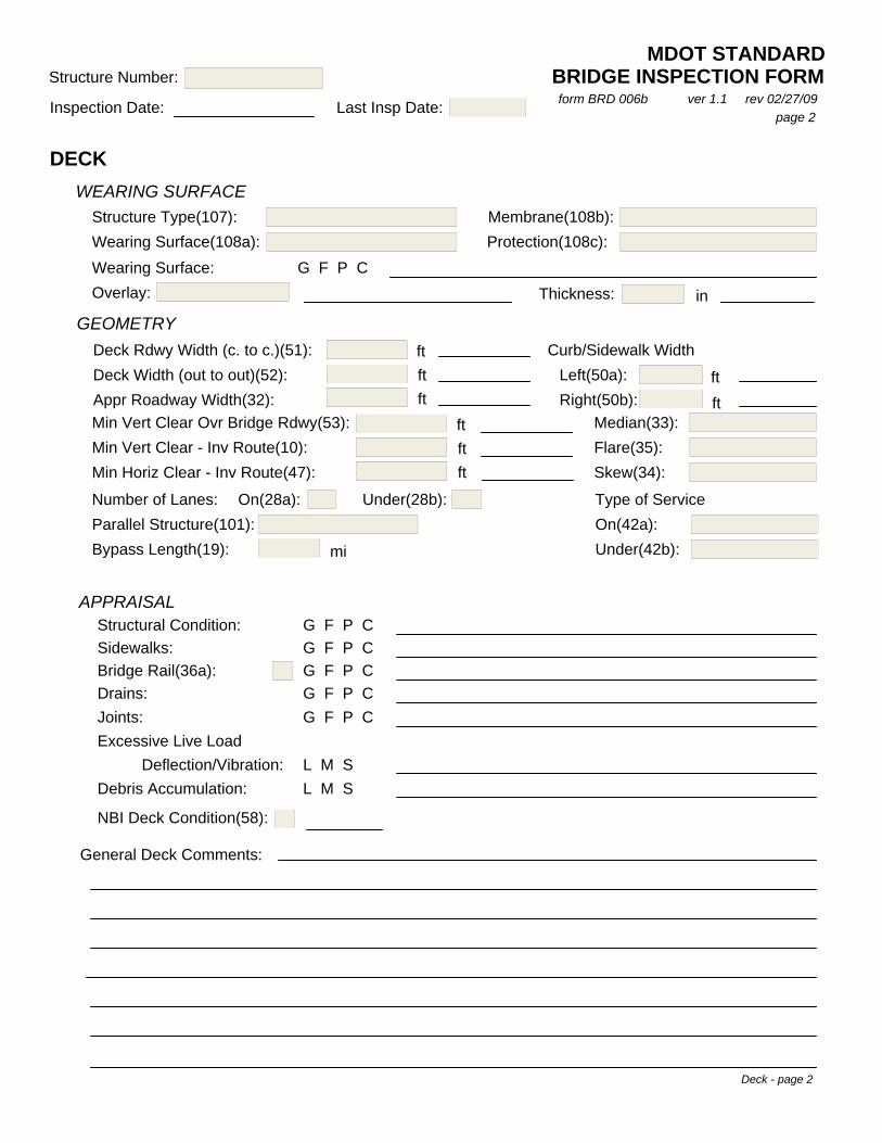
DECK
MDOT STANDARDBRIDGE INSPECTION FORM
Last Insp Date:Inspection Date:
Structure Number:
WEARING SURFACEStructure Type(107):Wearing Surface(108a): 1Wearing Surface: G F P COverlay:
Membrane(108b):Protection(108c):
GEOMETRY
Deck Width (out to out)(52):Appr Roadway Width(32):
Deck Rdwy Width (c. to c.)(51): ftftft
Curb/Sidewalk WidthLeft(50a):Right(50b):
ftft0.00
Median(33):Flare(35):Skew(34):
Min Vert Clear Ovr Bridge Rdwy(53):Min Vert Clear - Inv Route(10):Min Horiz Clear - Inv Route(47):
ftftft
APPRAISAL
Excessive Live Load
Structural Condition:Sidewalks:
Drains:Joints:
Deflection/Vibration:
G F P CG F P CG F P CG F P CG F P C
L M SL M SDebris Accumulation:
General Deck Comments:
00
NBI Deck Condition(58):
form BRD 006b ver 1.1 rev 02/27/09page 2
Thickness: in
46.83
327.755901043.99934338
Bridge Rail(36a):
Number of Lanes:Parallel Structure(101):Bypass Length(19):
On(28a): Under(28b): Type of ServiceOn(42a):Under(42b):mi
15
Deck - page 2
310003007302050
2/16/2010
1 00
43.9993433
43.9993433
327.76 0
0.00
2 0N9.942209
1
8

SUPERSTRUCTURE
BRIDGE INSPECTION FORMMDOT STANDARD
Structure Number:
Inspection Date: Last Insp Date:
GEOMETRYStructure Length(49): Max Span Length(48):ft ftMain Span Unit
Spans in Appr Unit(46):02 Stringer/Girder
Material Type(43a):Design Type(43b):
Spans in Main Unit(45):02 Stringer/Girder
Appr Span Unit
Material Type(44a):Design Type(44b):
NMin Vert Undrclear(54b):
Min Horiz Undrclearft Ref Feature(54a):
Ref Feature(55a):
Left(56): ft Right(55b): ft
APPRAISAL
form BRD 006b ver 1.1 rev 02/27/09page 3
Diaphragms:Floor Beams:Stringers: G F P C
G F P CG F P C
Superstructure - page 3
6 P/S Conc Continuous 6 P/S Conc Continuous
4
N
00.00
281.50
2
00.00
00.00
60.00
310003007302050
2/16/2010
Girders: G F P CSteel Risers: G F P C
Indications that Flood Waters Reach Superstructure: Yes No
Hinge Pins/Hangers: G F P CSway Bracing:Paint:
Cap/Girder Debris: L M SCollision Damage: Yes No
Cause of Debris: Open Joint Floodwater Other
G F P CG F P C
NBI Superstructure Rating(59):
General Superstructure Comments:
8

SUBSTRUCTURE
Navigation Control(38):Nav Vert Clear(39):
Structure Number:
Inspection Date: Last Insp Date:
MDOT STANDARDBRIDGE INSPECTION FORM
Pier Protection(111):Nav Horiz Clear(40): ftft
ABUTMENTS
CapWingsBackwall
G F P CG F P CG F P C
Bearing G F P C
form BRD 006b ver 1.1 rev 02/27/09page 4
General Substructure Comments
Web WallsBracingScour UnderminingHigh Water Mark
G F P CG F P C L M S
Yes No
NBI Substructure Rating(60):
Underwater Inspection Reqd(92b):
INTERMEDIATE BENTS
CapColumns/PilesFootings
G F P CG F P CG F P C
Bearing G F P C
Footings G F P C
G F P CG F P CPiles
Bulkhead
Scour UnderminingHigh Water Mark
L M SYes No
Embankment G F P CSlope PavingRiprap
G F P CG F P C
Substructure - page 4
310003007302050
2/16/2010
!00.0000.00
0
N
8

SCOUR / WATERWAY APPRAISAL
Scour Critical Bridge(113):
Structure Number:
Inspection Date: Last Insp Date:BRIDGE INSPECTION FORM
MDOT STANDARD
Scour Indicator:
form BRD 006b ver 1.1 rev 02/27/09page 5
Sediment and/or Gravel Accumulation: L M SStreambed Aggradation Evident: Y N ________________ Degradation: Y N ________________Channel has been Altered and/or Straightened: Y N U
Waterway Obstructions (ie, jetties, beaver dams, etc):
Abutment(s) Encroach into Channel: Y N
Indications of Scour (blowhole): Y N
Indications that Flood Waters Overtop Bridge and/or Approaches:
Location:
Site L M S Downstream L M SUpstream L M S
Debris/Drift Downstream:
Debris/Drift at Site:
Debris/Drift Upstream: ( )
( )
( )
Low Growth:
Large Timber:
Clear Banks:
( )
( )
( )
Bank Erosion/Failure:
Bank Vegetation:
Primary Bank Protection:Secondary Bank Protection 1 :Secondary Bank Protection 2:
Stream Velocity: Dry L M H
Has Channel Shifted: Yes No Not Apparent
Streambed Material:
NBI Channel/Channel Protection Rating(61):
Waterway Adequacy(71):
Scour Countermeasures in Place: Yes No If Yes, Countermeasure Condition: G F P C
Unknown Foundation:
General Scour Comments:
Y N Occasionally Frequently Unknown
Scour - page 5
310003007302050
2/16/2010
8
-1
8
8

INSPECTION TEAM SUMMARY
Structure Number:
Inspection Date: Last Insp Date:
MDOT STANDARDBRIDGE INSPECTION FORM
form BRD 006b ver 1.1 rev 02/27/09page 6
Date:Team Leader Signature:
Reviewed by DBIE: Date:
Inspection Summary - page 6
310003007302050
2/16/2010
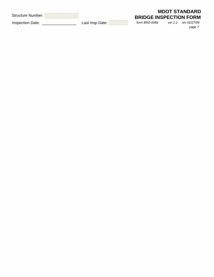
Structure Number:
Inspection Date: Last Insp Date: form BRD 006b ver 1.1 rev 02/27/09page 7
BRIDGE INSPECTION FORMMDOT STANDARD
310003007302050
2/16/2010

00.00
210006100103300
County: District:
MDOT STANDARDBOX CULVERT INSPECTION FORM
Location: 5.2 MI N WILKINSON CL
INDIAN VILLAGE BAYOUFeature Intrsctd:Facility Carried:
Bridge ID:
Inspection Date:
Fracture Critical: FC Member:
Team Members:
Time:
Last Insp Date: Insp Freq(91): moWeather
form BRD 006c ver 1.1 rev 03/02/09page 1
Initial
In-Depth
Special
Inspection Type:
Routine
Damage
Utility Attachment 2:Utility Attachment 1:
Digital Photos Available:
MISCELLANEOUS
GEOMETRY
ft Bypass Length(19): mi
ft Skew(34):
Min Horiz Clear - Inv Route(47):
Appr Roadway Width(32):
Min Vert Clear - Inv Route(10): ft328.05
Parallel Structure(101):Number of Lanes On(28a):
19 Culvert
Main Span Material Type(43a):
Main Span Design Type(43b):Spans in Main Unit(45):
Structure Length(49):Max Span Length(48):
ft
ft
21.98
Fill Height: ft
Barrel Length: ft00.00Cell Height: ft00.00Cell Width: ft
Number of Cells:
WEARING SURFACEWearing Surface: G F P COverlay: Thickness: in
SIGNINGyes no neededyes no needed
yes no needed
yes no needed
End of Bridge Markers:
Vertical Clearance:
Other:
TRAFFIC SAFETY FEATURESRail Transitions(36b):
Appr Guardrail(36c):
Appr Guardrail Ends(36d): N
NG F P C
G F P C
G F P C
Appr Transition: Good (<3/4") Deficient (>3/4")
Appr Rdwy Condition: G F P C
Approach/Geometry - page 1
Structure Number:10011Adams 07
US 61
8/21/2008 24
N _
N
327.755901
A
83.9895001
4
1 Concrete
1
20.01 00.00
0
N
3.2808397
102.01
N
U
N
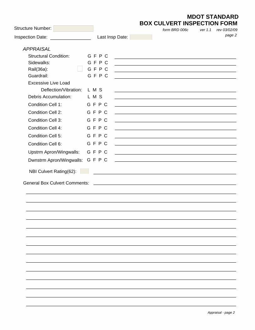
MDOT STANDARDBOX CULVERT INSPECTION FORM
Last Insp Date:Inspection Date:
Structure Number: form BRD 006c ver 1.1 rev 03/02/09page 2
APPRAISALStructural Condition:Sidewalks:Rail(36a):Guardrail:Excessive Live Load
Deflection/Vibration: L M SL M SDebris Accumulation:
Condition Cell 3:
Condition Cell 4:
G F P CG F P CG F P CG F P C
Condition Cell 1:
Condition Cell 2:
G F P C
G F P C
G F P C
G F P C
Condition Cell 5:
Condition Cell 6:
Upstrm Apron/Wingwalls:
Dwnstrm Apron/Wingwalls:
G F P C
G F P C
G F P C
G F P C
General Box Culvert Comments:
NBI Culvert Rating(62):
Appraisal - page 2
210006100103300
8/21/2008
N
7

SCOUR / WATERWAY APPRAISAL
Stream Velocity: Dry L M H
Has Channel Shifted: Yes No Not Apparent
Scour Critical Bridge(113):
Scour Countermeasures in Place: Yes No If Yes, Countermeasure Condition: G F P C
Streambed Material:
Scour Indicator:
NBI Channel/Channel Protection Rating(61):
Waterway Adequacy(71):
Site L M S Downstream L M SUpstream L M S
Debris/Drift Downstream:
Debris/Drift at Site:
Debris/Drift Upstream: ( )
( )
( )
Low Growth:
Large Timber:
Clear Banks:
( )
( )
( )
GG
Bank Erosion/Failure:
Bank Vegetation:
Primary Bank Protection:Secondary Bank Protection 1 :Secondary Bank Protection 2:
Sediment and/or Gravel Accumulation: L M SStreambed Aggradation Evident: Y N Degradation: Y NChannel has been Altered and/or Straightened: Y N U
Waterway Obstructions (ie, jetties, beaver dams, etc):
BOX CULVERT INSPECTION FORMMDOT STANDARD
Structure Number:
Inspection Date: Last Insp Date: form BRD 006c ver 1.1 rev 03/02/09page 3
Scour - page 3
Indications of Scour (blowhole): Y N
Indications that Flood Waters Overtop Bridge: Y N Occasionally Frequently Unknown
Location:
General Scour Comments:
210006100103300
8/21/2008
U8
7
8
R

INSPECTION TEAM SUMMARY
MDOT STANDARDBOX CULVERT INSPECTION FORMStructure Number:
Inspection Date: Last Insp Date:form BRD 006c ver 1.1 rev 03/02/09
page 4
Inspection Summary - page 4
Date:Reviewed by DBIE:
Team Leader Signature: Date:
210006100103300
8/21/2008
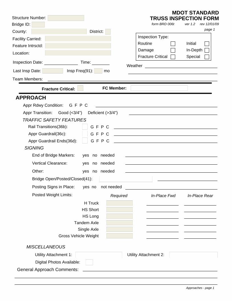
County: District:
Location:
Feature Intrsctd:Facility Carried:
Bridge ID:Structure Number:
Inspection Date:
Team Members:
Last Insp Date:
APPROACHAppr Rdwy Condition: G F P C
Appr Transition: Good (<3/4") Deficient (>3/4")
Time:
Insp Freq(91): mo
Inspection Type:
page 1
Fracture Critical: FC Member:
TRAFFIC SAFETY FEATURES
G F P C
G F P C
G F P C
Rail Transitions(36b):
Appr Guardrail(36c):
Appr Guardrail Ends(36d):
11
SIGNING
Posting Signs in Place: yes no not needed
Bridge Open/Posted/Closed(41):
yes no neededEnd of Bridge Markers: yes no needed
Vertical Clearance: yes no needed
Other: yes no needed
Posted Weight Limits: In-Place Fwd In-Place Rear
Weather
Routine Initial
SpecialIn-Depth
Fracture CriticalDamage
General Approach Comments:
Approaches - page 1
MISCELLANEOUS
Utility Attachment 1: Utility Attachment 2:
Digital Photos Available:
H TruckHS ShortHS Long
Tandem AxleSingle Axle
Gross Vehicle Weight
Required
21000490143371016242Coahoma 02
US 49
MISSISSIPPI RIVER
MISS/AR STATE LINE
10/21/2008 24
Y -1
1
A Open, no restriction
TRUSS INSPECTION FORMform BRD 006t ver 1.2 rev 12/01/09
MDOT STANDARD

DECK
Last Insp Date:Inspection Date:
Structure Number:
WEARING SURFACEStructure Type(107):Wearing Surface(108a): 1Wearing Surface: G F P COverlay:
Membrane(108b):Protection(108c):
GEOMETRY
Deck Width (out to out)(52):Appr Roadway Width(32):
Deck Rdwy Width (c. to c.)(51): ftftft
Curb/Sidewalk WidthLeft(50a):Right(50b):
ftft0.00
Median(33):Flare(35):Skew(34):
Min Vert Clear Ovr Bridge Rdwy(53):Min Vert Clear - Inv Route(10):Min Horiz Clear - Inv Route(47):
ftftft
APPRAISAL
Excessive Live Load
Structural Condition:Sidewalks:
Drains:Joints:
Deflection/Vibration:
G F P CG F P CG F P CG F P CG F P C
L M SL M SDebris Accumulation:
General Deck Comments:
00
NBI Deck Condition(58):
page 2
Thickness: in
31.20
17.4999998529.19999861
Bridge Rail(36a):
Number of Lanes:Parallel Structure(101):Bypass Length(19):
On(28a): Under(28b): Type of ServiceOn(42a):Under(42b):mi
15
Deck - page 2
210004901433710
10/21/2008
1 00
40.0000001
27.9999991
17.40 0
0.00
2 0N123.7030
1
6
MDOT STANDARDTRUSS INSPECTION FORMform BRD 006t ver 1.2 rev 12/01/09

SUPERSTRUCTURE
Structure Number:
Inspection Date: Last Insp Date:
GEOMETRYStructure Length(49): Max Span Length(48):ft ft
Spans in Appr Unit(46):03 Girder-Floorbeam
Material Type(43a):Design Type(43b):
Spans in Main Unit(45):10 Truss-Thru
Material Type(44a):Design Type(44b):
NMin Vert Undrclear(54b):
Min Horiz Undrclearft Ref Feature(54a):
Ref Feature(55a):
Left(56): ft Right(55b): ft
APPRAISAL
page 3
Diaphragms:Floor Beams:Stringers: G F P C
G F P CG F P C
Superstructure - page 3
3 Steel 3 Steel
16
N
327.76
5204.00
5
00.00
00.00
840.00
210004901433710
10/21/2008
MDOT STANDARDTRUSS INSPECTION FORMform BRD 006t ver 1.2 rev 12/01/09
Main Span Unit Appr Span Unit
Girders: G F P CGirders: G F P C
NBI Superstructure Rating(59):
General Superstructure Comments:
4
Indications that Flood Waters Reach Superstructure: Yes No
Hinge Pins/Hangers: G F P CSway Bracing:Paint:
Cap/Girder Debris: L M SCollision Damage: Yes No
Cause of Debris: Open Joint Floodwater Other
G F P CG F P C

TRUSS
Portals:
Chords - Top
Chords - Bottom:
Verticals:
Diagonals:
Sway Bracing:
Top Lateral Struts:
Top Lateral "X" Bracing:
End Posts: G F P C
G F P C
G F P C
G F P C
G F P C
G F P C
G F P C
G F P C
G F P C
G F P CBottom Laterals:
page 4form BRD 006t ver 1.2 rev 12/01/09
MDOT STANDARDTRUSS INSPECTION FORM
Last Insp Date:
Structure Number:
Inspection Date:
General Truss Comments:
Truss - page 4

SUBSTRUCTURE
Navigation Control(38):Nav Vert Clear(39):
Pier Protection(111):Nav Horiz Clear(40): ftft
ABUTMENTS
CapWingsBackwall
G F P CG F P CG F P C
Bearing G F P C
General Substructure Comments
Web WallsBracingScour UnderminingHigh Water Mark
G F P CG F P C L M S
Yes No
NBI Substructure Rating(60):
Underwater Inspection Reqd(92b):
INTERMEDIATE BENTS
CapColumns/PilesFootings
G F P CG F P CG F P C
Bearing G F P C
Footings G F P C
G F P CG F P CPiles
Bulkhead
Scour UnderminingHigh Water Mark
L M SYes No
Embankment G F P CSlope PavingRiprap
G F P CG F P C
Substructure - page 5
1719.8059.70
1
Y
7
Structure Number:
Inspection Date: Last Insp Date:
210004901433710
10/21/2008
210004901433710
10/21/2008page 5
MDOT STANDARDTRUSS INSPECTION FORMform BRD 006t ver 1.2 rev 12/01/09

SCOUR / WATERWAY APPRAISAL
Scour Critical Bridge(113):
Structure Number:
Inspection Date: Last Insp Date:
Scour Indicator:
page 6
Sediment and/or Gravel Accumulation: L M SStreambed Aggradation Evident: Y N ________________ Degradation: Y N ________________Channel has been Altered and/or Straightened: Y N U
Waterway Obstructions (ie, jetties, beaver dams, etc):
Abutment(s) Encroach into Channel: Y N
Indications of Scour (blowhole): Y N
Indications that Flood Waters Overtop Bridge and/or Approaches:
Location:
Site L M S Downstream L M SUpstream L M S
Debris/Drift Downstream:
Debris/Drift at Site:
Debris/Drift Upstream: ( )
( )
( )
Low Growth:
Large Timber:
Clear Banks:
( )
( )
( )
Bank Erosion/Failure:
Bank Vegetation:
Primary Bank Protection:Secondary Bank Protection 1 :Secondary Bank Protection 2:
Stream Velocity: Dry L M H
Has Channel Shifted: Yes No Not Apparent
Streambed Material:
NBI Channel/Channel Protection Rating(61):
Waterway Adequacy(71):
Scour Countermeasures in Place: Yes No If Yes, Countermeasure Condition: G F P C
Unknown Foundation:
General Scour Comments:
Y N Occasionally Frequently Unknown
Scour - page 6
210004901433710
10/21/2008
5
-1
8
7
MDOT STANDARDTRUSS INSPECTION FORMform BRD 006t ver 1.2 rev 12/01/09

INSPECTION TEAM SUMMARY
Structure Number:
Inspection Date: Last Insp Date:page 7
Date:Team Leader Signature:
Reviewed by DBIE: Date:
Inspection Summary - page 7
210004901433710
10/21/2008TRUSS INSPECTION FORMform BRD 006t ver 1.2 rev 12/01/09
MDOT STANDARD

Structure Number:
Inspection Date: Last Insp Date:page 8
210004901433710
10/21/2008
MDOT STANDARDTRUSS INSPECTION FORM
form BRD 006t ver 1.2 rev 12/01/09

District: 05
BRIDGE CRITICALStructure Number: 210008005112250 DEFICIENCY REPORT
form BRD 008 ver 2.0 rev 05/04/09Bridge ID: 13542
Location:Feature Intersected:Facility Carried:US 80
NewtonCounty: 6.2 MI E SR 503CHUNKY RIVER
CompleteStatus: Sufficiency Rating: 44.5Report Date: 2/25/2009
Description of Deficiency:After pumping the scour hole out at spans 1 and 2 and 3, the top of the footings are exposed at bent 2 and almost at bent 3, column 2.This scour has been present for years and has never been underwater inspected. The footing is only 14" thick.
Date Work Completed:
Action Taken:
Item Closedin Database: yes ___ Date:
Bridge Inspection Team Leader
Distribution:Deputy Executive Director/Chief EngineerAssistant Chief Engineer - Operational MaintenanceDistrict EngineerState Maintenance EngineerBridge EngineerDirector of Law EnforcementFHWA, Division Bridge Engineer

District: 05
BRIDGE HAZARDOUSStructure Number: 210008005112250 DEFICIENCY REPORT
form BRD 009 ver 2.0 rev 05/04/09Bridge ID: 13542
Location:Feature Intersected:Facility Carried:US 80
NewtonCounty: 6.2 MI E SR 503CHUNKY RIVER
CompleteStatus: Sufficiency Rating: 44.5Report Date: 2/25/2009
Description of Deficiency:After pumping the scour hole out at spans 1 and 2 and 3, the top of the footings are exposed at bent 2 and almost at bent 3, column 2.This scour has been present for years and has never been underwater inspected. The footing is only 14" thick.
Date Work Completed:
Action Taken:
Item Closedin Database: yes ___ Date:
Bridge Inspection Team Leader
Distribution:Deputy Executive Director/Chief EngineerAssistant Chief Engineer - Operational MaintenanceDistrict EngineerState Maintenance EngineerBridge EngineerDirector of Law EnforcementFHWA, Division Bridge Engineer

Bridge Inspector Experienceand Training Record
Major Years
Hours Sponsor Date
Hours Sponsor Date
Years
Supervisor's Signature ________________________________________________ Date _________________
Date _________________
Supervisor's Name (Print) ____________________________________ Title ___________________________
Bridge Inspection PM _________________________________________________
Having reviewed the above information, I conclude that this individual meets the minimum qualifications for a bridge inspector/team leader
as prescribed in the current 23 CFR 650.309.
Inspector's Signature _________________________________________________
To the best of my knowledge, the above information is true and accurate.
Date _________________
Bridge Inspection Experience Bridge Duties
Inspector's Name
Title
Education/Institution Degree
Professional Registration Registration Number
Date
Bridge Inspection Training
Special Technical Course(s)
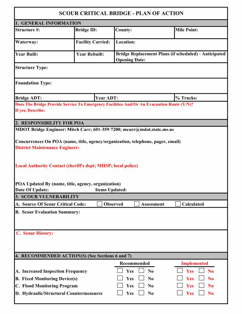
SCOUR CRITICAL BRIDGE - PLAN OF ACTION
1. GENERAL INFORMATIONStructure #: Bridge ID: County: Mile Point:
Waterway: Facility Carried: Location:
Year Built: Year Rebuilt: Bridge Replacement Plans (if scheduled) - Anticipated Opening Date:
Structure Type:
Foundation Type:
Bridge ADT: Year ADT: % Trucks:Does The Bridge Provide Service To Emergency Facilities And/Or An Evacuation Route (Y/N)?If yes, Describe:
2. RESPONSIBILITY FOR POAMDOT Bridge Engineer:
Concurrences On POA (name, title, agency/organization, telephone, pager, email)District Maintenance Engineer:
Local Authority Contact (sheriff's dept; MHSP; local police)
POA Updated By (name, title, agency, organization)Date Of Update: Items Updated:3. SCOUR VULNERABILITYA. Source Of Scour Critical Code: Observed Assessment Calculated B. Scour Evaluation Summary:
C. Scour History:
4. RECOMMENDED ACTION(S) (See Sections 6 and 7)Recommended Implemented
A. Increased Inspection Frequency Yes No Yes NoB. Fixed Monitoring Device(s) Yes No Yes NoC. Flood Monitoring Program Yes No Yes NoD. Hydraulic/Structural Countermeasures Yes No Yes No

5. NBI CODING INFORMATIONInspection DateItem 113 Scour CriticalItem 60 Substructure Item 61 Channel & Channel Protection
Item 71 Waterway AdequacyComments: (drift, Scour holes, etc.)
6. PLAN OF ACTION
Only Monitoring Required:
District, County, and Individual Responsible for Monitoring:
Responsible Individual's Contact Information (telephone, cell, pager, email):
Structural/Hydraulic Countermeasures Considered:
Countermeasure Implementation Project Type:Proposed Construction ProjectDistrict Maintenance ProjectTarget Construction Completion Date:
Countermeasure Completed:7. BRIDGE CLOSURE PLANAgency And Department Responsible For Closure:
Contact Persons (name, title, telephone, pager,email)
Scour Monitoring Criteria For Consideration Of Bridge Closure:
Emergency Repair Plans (include sources, contacts, cost, installation directions):
Criteria For Re-Opening The Bridge:
Agency And Person Responsible For Re-Opening The Bridge After Inspection:

9. DETOUR ROUTEDetour Route Description (route number, from/to, distance from bridge, etc.) -
Bridges On Detour Route: (State Maintained Only)
Bridge Number WaterwaySufficiency Rating/ Load
Limitations Item 113 Code
Traffic Control Equipment (detour signing and barriers) and Locations:
Additional Considerations Or Critical Issues (susceptibility to overtopping, limited waterway adequacy, land restriction, etc.):
New Release, Other Public Notice (include authorized persons, information to be providedand limitations):

FRACTURE CRITICAL BRIDGE INSPECTION PROCEDURE
Special Equipment Required
Inspection Procedure
Purpose: Identify the location of Fracture Critical Members (FCM) and describe the required inspection procedure.
Definition: A FCM is a steel member in tension, or with a tension element, whose failure would probably cause a
portion of or the entire bridge to collapse.
Procedure:
1) All FCM shall receive a very detailed, close visual “hands-on” inspection of all surface areas. To assist the inspector in identifying FCM, these designated members are color highlighted on the contract plan drawings previously provided to the inspector. As necessary, surface areas should be properly cleaned to allow a thorough inspection. Additional lighting and magnification may be required. Special attention shall be given to areas vulnerable to corrosion, sudden change in cross-section such as cover plates, field welds, and any discontinuities resulting in stress risers. Note any evidence of corrosion, cracks, defects, warping, or damage. Check for any out-of-plane bending that could result in fatigue cracks and prying action that may occur at bolted/riveted connection plates. Take digital photographs as necessary to aid in documenting the deficiencies.
2) In the event that a crack in the FCM is suspected an in-depth inspection such as NDT (dye penetrant or UT) shall be used to confirm the existence and size of the crack. Particular care should be taken to document the size and length of any crack.
3) Upon discovery of a crack, or defect, in a FCM which could threaten the structural stability of the bridge, the BITC (or Team Leader) shall take immediate action to ensure public safety by closing the bridge to all traffic and subsequently follow the critical findings procedures prescribed in MDOT’s Bridge Safety Inspection Policy and Procedure Manual.
Structure #
Yes No
Structure Key County
Feature Int. Location
Facility Mile Post ADTYear Built Year ADT
Fracture Critical Member (s)
Inspection Frequency
Date Created
Effective Date: 02/18/2009

APPENDIX F
AASHTO and State-Specific CoRe Elements

F-1
Deck/Slab Elements Concrete Decks/Slabs Without AC Overlay 12 Concrete Deck--- Bare (EA) This element defines those concrete bridge decks
with no surface protection of any type and constructed with uncoated reinforcement.
26 Concrete Deck--- Protected with Coated Bars (EA) This element defines those concrete bridge decks constructed with (epoxy, galvanized, stainless steel, etc.) coated reinforcement bar.
27 Concrete Deck--- Protected with Cathodic System (EA) This element defines those concrete bridge decks protected with a cathodic system.
375 Integral Concrete Deck---Bare (EA) This element defines those concrete bridge decks where the deck is an integral part of the load-carrying capacity of the structure (box girder, tee-beam).
38 Concrete Slab---Bare (EA) This element defines those concrete slab bridges with no surface protection of any type and constructed with uncoated reinforcement.
52 Concrete Slab---Protected with Coated Bars (EA) This element defines those concrete slab bridges constructed with (epoxy, galvanized, stainless steel, etc.) coated reinforcement bar.
53 Concrete Slab---Protected with Cathodic System (EA) This element defines those concrete slab bridges protected with a cathodic system.
369 Choctaw Slab---Bare (EA) This element defines those slab bridges constructed with precast Choctaw slab units.
371 Voided Slab---Bare (EA) This element defines those slab bridges constructed with precast voided slab units.
373 Prestressed Voided Slab---Bare (EA) This element defines those slab bridges constructed with precast, prestressed voided slab units.
Concrete Decks/Slabs With AC Overlay 13 Concrete Deck--- Unprotected with AC Overlay (EA) This element defines
those concrete bridge decks with no surface protection of any type. The deck is covered with an asphaltic concrete overlay.
14 Concrete Deck---Protected with AC Overlay (EA) This element defines those concrete bridge decks protected with a membrane. The membrane is covered with an asphaltic concrete overlay.
F-2
376 Integral Concrete Deck with AC Overlay (EA) This element defines those concrete bridge decks where the deck is an integral part of the load-carrying capacity of the structure (box girder, tee-beam). . The deck is covered with an asphaltic concrete overlay.
39 Concrete Slab--- Unprotected with AC Overlay (EA) This element defines those concrete slab bridges with no surface protection of any type. The deck is covered with an asphaltic concrete overlay.
40 Concrete Slab--- Protected with AC Overlay (EA) This element defines those concrete slab bridges protected with a membrane. The membrane is covered with an asphaltic concrete overlay.
370 Choctaw Slab with AC Overlay (EA) This element defines those slab bridges constructed with precast Choctaw slab units. The deck is covered with an asphaltic concrete overlay.
372 Voided Slab with AC Overlay (EA) This element defines those slab bridges constructed with precast voided slab units. The deck is covered with an asphaltic concrete overlay.
374 Prestressed Voided Slab with AC Overlay (EA) This element defines those concrete slab bridges constructed with precast, prestressed voided slab units. The deck is covered with an asphaltic concrete overlay.
Concrete Decks/Slabs With Thin/Rigid Overlay 18 Concrete Deck--- Protected with Thin Overlay (EA) This element defines
those concrete bridge decks protected with a thin (<25mm) overlay (Portland cement, polymer, etc.).
22 Concrete Deck--- Protected with Rigid Overlay (EA) This element defines those concrete bridge decks protected with a rigid (>25mm) overlay (low-slump Portland cement, polymer, etc.).
44 Concrete Slab--- Protected with Thin Overlay (EA) This element defines those concrete slab bridges protected with a thin (<25mm) overlay (Portland cement, polymer, etc.).
48 Concrete Slab--- Protected with Rigid Overlay (EA) This element defines those concrete slab bridges protected with a rigid (>25mm) overlay (low-slump Portland cement, polymer, etc.).
Timber Decks/Slabs 31 Timber Deck--- (EA) This element defines those bridge decks that are
constructed of timber and are not overlaid.
32 Timber Deck--- with AC Overlay (EA) This element defines those bridge decks that are constructed of timber and are overlaid with asphaltic concrete.

F-3
54 Timber Slab (EA) This element defines those slab span bridges that are constructed of timber and are not overlaid.
55 Timber Slab--- with AC Overlay (EA) This element defines those slab span bridges that are constructed of timber and are overlaid with asphaltic concrete.
Steel Decks 28 Steel--- Open Grid (EA) This element defines those bridge decks that are
constructed of steel grids that are open and unfilled.
29 Steel--- Concrete Filled Grid (EA) This element defines those bridge decks that are constructed of steel grids with either all of the openings or just those in the wheel tracks filled with concrete.
30 Steel--- Corrugated/Orthotropic/Etc. (EA) This element defines those bridge decks that are constructed of corrugated metal filled with Portland cement concrete or asphaltic concrete. Orthotropic steel decks are also included.
Superstructure and Substructure Unpainted Steel 101 Closed Web/Box Girder (m) This element defines only those steel closed
web/box girder units that are not painted or are constructed of weathering steel.
106 Open Girder/Beam (m) This element defines only those steel open girder units that are not painted or are constructed of weathering steel. This element includes two-girder systems as well as rolled beams on multiple-beam spans.
366 Plate Girder (m) This element defines only those steel open girder units that are fabricated from steel plates, angles, and channels with welded, bolted or riveted connections. Steel is not painted or is fabricated from weathering steel.
112 Stringer (stringer-floor beam system) (m) This element defines all unpainted steel stringers that support the deck in a stringer-floor beam system.
120 Through Truss (bottom chord) (m) This element defines the bottom chord of unpainted steel trusses or those constructed of weathering steel. This element includes through trusses and pony trusses.
125 Through Truss (excluding bottom chord) (m) This element defines all truss elements except the bottom chord of unpainted steel trusses or those constructed of weathering steel. This element includes through trusses and pony trusses.
130 Deck Truss (m) This element defines all members of unpainted steel deck trusses or those constructed of weathering steel.
140 Arch (m) This element defines all members of only those steel arches that are not painted or are constructed of weathering steel.

F-4
151 Floor Beam (m) This element defines only those steel floor beams that are not painted or are constructed of weathering steel.
201 Column or Pile Extension (EA) This element defines only those columns or pile extensions that are unpainted or are constructed of weathering steel.
225 Submerged Pile (EA) This element defines only those unpainted steel piles that are continuously submerged and are visible for inspection. The exposure may be intentional or caused by scour.
230 Pier Cap (m) This element defines only those steel pier caps that are not painted or are constructed of weathering steel.
Painted Steel 102 Closed Web/Box Girder (m) This element defines only those steel closed
web/box girder units that are painted.
107 Open Girder/Beam (m) This element defines only those steel open girder units that are painted. This element includes two-girder systems as well as rolled beams on multiple-beam spans.
367 Plate Girder (m) This element defines only those steel open girder units that are fabricated from steel plates, angles, and channels with welded, bolted or riveted connections. Steel is painted.
113 Stringer (stringer-floor beam system) (m) This element defines all painted steel stringers that support the deck in a stringer-floor beam system.
121 Through Truss (bottom chord) (m) This element defines the bottom chord of steel trusses that are painted. This element includes through trusses and pony trusses.
126 Through Truss (excluding bottom chord) (m) This element defines all truss elements except the bottom chord of steel trusses that are painted. This element includes through trusses and pony trusses.
131 Deck Truss (m) This element defines all members of painted steel deck trusses.
141 Arch (m) This element defines all members of only those steel arches that are painted.
152 Floor Beam (m) This element defines only those steel floor beams that are painted.
202 Column or Pile Extension (EA) This element defines only those columns or pile extensions that are painted.
368 Concrete-encased Steel Pile (EA) This element defines only those piles which have been encased in concrete.
231 Cap (m) This element defines only those steel pier caps that are painted.

F-5
Reinforced Concrete 105 Closed Web/Box Girder (m) This element defines only those closed web/box
girder units constructed of reinforced concrete.
110 Open Girder/Beam (m) This element defines only those open girder units constructed of reinforced concrete. This element includes two-girder systems as well as reinforced concrete beams on multiple-beam spans.
116 Stringer (stringer-floor beam system) (m) This element defines only those reinforced concrete stringers that support the deck in a stringer-floor beam system.
144 Arch (m) This element defines only those arches constructed of reinforced concrete.
155 Floor Beam (m) This element defines only those floor beams constructed of reinforced concrete.
205 Driven Pile or Pile Extension (EA) This element defines only those driven piles or pile extensions that are constructed of precast reinforced concrete.
365 Cast-in-Place Column (EA) This element defines those columns which are constructed of cast-in-place reinforced concrete.
210 Pier Wall (m) This element defines only those pier walls (shafts) constructed of reinforced concrete.
215 Abutment (m) This element defines only those abutments constructed of reinforced concrete.
220 Submerged Pile Cap/Footing (EA) This element defines only those reinforced concrete pile caps and/or footings that are continuously submerged and are visible for inspection. The exposure may be intentional or caused by scour.
227 Submerged Pile (EA) This element defines only those reinforced concrete piles that are continuously submerged and are visible for inspection. The exposure may be intentional or caused by scour.
377 Submerged Column (EA) This element defines only those reinforced concrete columns that are continuously submerged and are visible for inspection. The exposure may be intentional or caused by scour.
234 Cap (m) This element defines only those pier caps that are constructed of reinforced concrete.
Pre-stressed Concrete 104 Closed Web/Box Girder (m) This element defines only those closed web/box
girder units constructed of prestressed concrete.
109 Open Girder/Beam (m) This element defines only those prestressed concrete open girder units constructed of prestressed concrete. This element includes two-girder systems as well as prestressed concrete beams on multiple-beam spans.
F-6
364 Bulb-T Girder (m) This element defines those prestressed concrete open girders with a Bulb-T design.
115 Stringer (stringer-floor beam system) (m) This element defines only those prestressed concrete stringers that support the deck in a stringer-floor beam system.
143 Arch (m) This element defines only those arches constructed of prestressed concrete.
154 Floor Beam (m) This element defines only those floor beams constructed of prestressed concrete.
204 Column or Pile Extension (EA) This element defines only those columns or pile extensions that are constructed of prestressed concrete.
226 Submerged Pile (EA) This element defines only those prestressed concrete piles that are continuously submerged and are visible for inspection. The exposure may be intentional or caused by scour.
233 Cap (m) This element defines only those pier caps that are constructed of prestressed concrete.
Timber 111 Open Girder/Beam (m) This element defines only those open girders of timber
construction. These can include either solid timber beams or glue-lam girders.
117 Stringer (stringer-floor beam system) (m) This element defines only those timber stringers that support the deck in a stringer-floor beam system.
135 Timber Truss/Arch (m) This element defines all members of trusses and arches that are constructed of timber.
156 Floor Beam (m) This element defines only those floor beams constructed of timber.
206 Column or Pile Extension (EA) This element defines only those columns or pile extensions that are constructed of timber.
216 Abutment (m) This element defines only those abutments constructed of timber.
228 Submerged Pile (EA) This element defines only those timber piles that are continuously submerged and are visible for inspection. The exposure may be intentional or caused by scour.
235 Cap (m) This element defines only those pier caps that are constructed of timber.
F-7
Other Elements Joints 300 Strip Seal Expansion Joint (m) This element defines only those expansion joint
devices that utilize a neoprene type waterproof gland with steel extrusion to anchor the gland.
301 Pourable Joint Seal (m) This element defines only those joints filled with a pourable seal.
302 Compression Joint Seal (m) This element defines only those joints filled with a preformed compression-type seal.
303 Assembly Joint Seal (modular) (m) This element defines only those joints filled with an assembly mechanism, which may or may not have a seal.
304 Open Expansion Joint (m) This element defines only those joints that are open and not sealed.
Bearings 310 Elastomeric Bearing (EA) This element defines only those bridge bearings that
are constructed primarily of elastomers, with or without fabric or metal reinforcement.
311 Movable Bearing (roller, sliding, etc.) (EA) This element defines only those bridge bearings that provide for both deflection and longitudinal movement by means of roller, rocker, or sliding mechanisms.
312 Enclosed/Concealed Bearing (EA) This element defines only those bridge bearings that are enclosed so that they are not open for detailed inspection.
313 Fixed Bearing (EA) This element defines only those bridge bearings that provide for deflection only.
314 Pot Bearing (EA) This element defines those high-load bearings with confined elastomer. The bearing may be fixed against horizontal movement, guided to allow movement in one direction or floating to allow sliding in any direction.
315 Disk Bearing (EA) This element defines those high-load bearings with a hard plastic disk. The bearing may be fixed against horizontal movement, guided to allow movement in one direction, or floating to allow sliding in any direction.
F-8
Approach Slabs 320 Approach Slab with/without AC Overlay --- Prestressed Concrete (EA) This
element defines those structural sections, with or without an asphalt overlay, between the abutment and the approach pavement that are constructed of prestressed concrete.
321 Approach Slab with or without AC Overlay --- Reinforced Concrete (EA) This element defines those structural sections, with or without an asphalt overlay, between the abutment and the approach pavement that are constructed of reinforced concrete.
Bridge Railings 330 Bridge Railing Metal Coated (m) This element defines all types and shapes of
metal bridge railing. Steel, aluminum, metal beam, rolled shapes, etc., are all considered part of this element. The element may be coated with paint or protected with galvanizing or some other coating.
331 Bridge Railing Reinforced Concrete (m) This element defines all types and shapes of reinforced concrete bridge railing. All elements of the railing must be concrete.
332 Bridge Railing Timber (m) This element defines all types and shapes of timber bridge railing.
333 Bridge Railing Other (m) This element defines all types and shapes of bridge railing except those defined as metal, concrete, or timber. This element may include combinations of materials.
334 Bridge Railing Metal Uncoated (m) This element defines all types and shapes of metal bridge railing. Steel, aluminum, metal beam, rolled shapes, etc., are all considered part of this element. The element is neither coated nor painted.
Culverts 240 Steel Culvert (along length of barrel) (m) This element defines all metal (steel,
aluminum, galvanized) culverts, including arches, round or elliptical pipes, etc.
241 Concrete Culvert (along length of barrel) (m) This element defines all precast and cast-in-place (conventional or prestressed) concrete arch, pipe, and box culverts.
242 Timber Culvert (along length of barrel) (m) This element defines all timber box culverts.
243 Culvert Other (along length of barrel) (m) This element defines all culverts not included under steel, concrete, or timber culverts. It includes masonry and combinations of other materials.

F-9
Other Elements 145 Arch (m) This element defines arches made of masonry or any other material
except steel, concrete, or timber.
146 Uncoated Cable (not embedded in concrete) (EA) This element defines only those steel cables not embedded in concrete.
147 Coated Cable (not embedded in concrete) (EA) This element defines only those steel cables not embedded in concrete.
160 Unpainted Steel Pin and/or Pin and Hanger Assembly (EA) This element defines only those steel pin and hanger assemblies that are either not painted or are constructed of weathering steel.
161 Painted Steel Pin and/or Pin and Hanger Assembly (EA) This element defines only those steel pin and hanger assemblies that are painted.
211 Pier Wall (m) This element defines only those pier walls (shafts) constructed of material other than reinforced concrete, such as masonry pier walls.
217 Abutment (m) This element defines abutments made of masonry or any other material except concrete or timber.
Smart Flags 356 Steel Fatigue (EA) This condition state language addresses only those bridges
with steel elements that are already showing fatigue damage. It should not be applied to steel bridges before fatigue damage becomes apparent. Once established, deterioration modeling can be used to obtain transition probabilities.
357 Pack Rust (EA) This condition state language addresses only those connections (including shapes in contact in built-up members) of steel bridges that are already showing signs of rust packing between steel plates.
358 Deck Cracking (EA) This condition state language addresses cracking on the top surface of concrete decks.
359 Soffit (or undersurface) of Concrete Deck or Slab (EA) This condition state language addresses deck distresses through visual inspections of the deck soffit (undersurface). It is extremely valuable when the top surface of the deck is covered with an overlay.
360 Settlement (EA) This condition state language addresses substructure settlement distresses that are evident during visual inspections. Its primary purpose is to identify bridges that are experiencing settlement and to provide some measure of the magnitude of that settlement. The normal condition state language for substructure elements does not address settlement.

F-10
361 Scour (EA) This condition state language addresses scour distresses that are evident during visual inspections. Its primary purpose is to identify bridges that are experiencing scour and to provide some measure of the magnitude of scour. This Smart Flag may not be needed if National Bridge Inventory Item 113 is used to record field observed scour.
362 Traffic Impact (EA) This condition state language addresses distress of any elements (mainly superstructure) due to traffic impact damage.
363 Section Loss (EA) This condition state language addresses section loss in areas of steel members that warrant analysis (e.g., beam/girder web in high-shear areas, beam/girder flanges in high-moment areas, bottom chords of through trusses, etc.). This Smart Flag should be used when a steel element reaches condition state 4, or for those elements that have section loss but have been repaired or cleaned and painted over.

APPENDIX G
Engineering Services Contract and Scope of Work for Underwater Bridge Inspection Services
LEGAL NOTICE The Mississippi Department of Transportation intends to employ an underwater diving firm to provide inspections on the foundations of approximately _____ bridges. These bridges are located throughout the state and include saltwater crossings as well as freshwater crossings. For selected bridges, portions of the bridges’ substructures and the channel bottom surrounding the substructures will be displayed and recorded with acoustic imaging using high resolution scanning sonar. In addition, heavy drift removal requiring the use of a heavy duty winch truck may be required at a number of sites. The department will utilize a Labor Hour / Unit Cost with an upset limit contract for the underwater inspection services. Diving firms interested in providing these services may so indicate by furnishing the Department seven (7) copies of the following:
1. A cover letter specifying the name and complete description of project, the name of the project manager, and the location and address of the office to be assigned the majority of the work;
2. A response containing the information upon which the consultant will be evaluated;
3. An organizational chart of all key personnel. 4. Proof that the Project Manager is licensed as a Mississippi Professional Engineer and that
the firm has met state licensure and certification requirements**;
5. A resume for each principal member, the project manager and employee(s) of the firm anticipated to be assigned to the project, listing each person's experience and qualifications. The resumes shall include an experience record for each Diver and Engineer that may be involved in this work; as well as a listing, by classification, of each employee (or prospective employee) who may be assigned to this work.
6. A firm must have, in addition to extensive underwater investigation experience, qualified
engineering personnel on its staff capable of rendering sound judgments and evaluations regarding the structural integrity of underwater bridge members.
7. All divers who may perform inspections shall have attended and successfully completed
an FHWA approved comprehensive bridge inspection training course or other FHWA approved underwater inspection training course as prescribed in the National Bridge Inspection Standards, 23 CFR 650.309. The firm shall provide copies of the certifications of training for the courses described above for each individual diver, including any certifications from subconsultants.
8. A description of similar type work completed during the past five (5) years with
approximately five (5) samples of underwater inspection reports which qualifies the firm for this work;
9. A description of a Quality Control and Quality Assurance (QC/QA) Plan that would be
used by your firm for underwater inspections and report preparations similar to this project; and
10. Standard Form (SF) 254, Architect-Engineer and Related Services Questionnaire.

The Department will evaluate the Expressions of Interest based on the following factors listed in their relative order of importance: the firm’s experience, performance, and qualifications performing NBI underwater bridge inspections with MDOT and/or other clients; the experience, qualifications, and performance of the engineering and diving staff that will be assigned to this project; the quality, clarity, and thoroughness of sample inspection reports; and the quality, clarity, and thoroughness of a QC/QA Plan description for a similar type project. MDOT reserves the right to select one (1) consultant or select a short list of consultants from whom more information will be required.
The DBE goal is 0%. To be considered, all replies must be received by ________________________, in the Office of the Consultant Services Director, Scot Ehrgott, Room 10083, Mississippi Department of Transportation Building, 401 North West Street, Jackson, Mississippi, 39201. This Legal Notice will appear in The Clarion Ledger on _______________________. The Mississippi Transportation Commission and the Mississippi Department of Transportation are equal opportunity employers. **Miss. Code Ann Sections 73-13-1 through 73-13-45 (1972) (as amended) govern the practice of engineering in Mississippi. Firms are encouraged to contact the Mississippi Board of Licensure for Professional Engineers and Surveyors at (601) 359-6160 to insure that individuals and firms are qualified to offer and provide services in the State of Mississippi. The Board’s web address is www.pepls.state.ms.us

1
ENGINEERING SERVICES CONTRACT
Underwater Bridge Inspection Services Project No. ####
Statewide
This CONTRACT, is made and entered into by and between the Mississippi Transportation Commission, a body Corporate of the State of Mississippi (the "COMMISSION"), acting by and through the duly authorized Executive Director of the Mississippi Department of Transportation and, CCCXXXX (the "CONSULTANT"), a XXXX Corporation, duly licensed and registered to do business in the State of Mississippi, whose address for mailing is XXXX. This CONTRACT shall be effective as of the date of latest execution below. WITNESSETH:
WHEREAS, the COMMISSION requires the services of an underwater diving firm to provide inspections on the foundations of approximately ### bridges located throughout the state, and include saltwater crossings as well as freshwater crossings, Statewide, Project No. ####, hereinafter called the “PROJECT”; and
WHEREAS, the COMMISSION desires to engage a qualified and experienced CONSULTANT to conduct said services as stated above, hereinafter called the "SERVICES"; and, WHEREAS, the CONSULTANT has represented to the COMMISSION that it is experienced and qualified to provide those services, and the COMMISSION has relied upon such representation; and WHEREAS, the CONSULTANT herein was chosen through the Consultant Selection Process pursuant to Mississippi Department of Transportation (hereinafter "MDOT") Standard Operating Procedure ADM-24-01-00-000 (March 1, 2001, as revised) and pursuant to Federal Highway Administration (“FHWA”) regulations, Engineering and Design Related Service Contracts, 23 C.F.R. Part 172 (as amended) and found satisfactory both by the COMMISSION and by the FHWA to the end that both parties are now desirous of entering into a CONTRACT; NOW, THEREFORE, for and in consideration of the mutual promises and covenants contained herein and for other good and valuable consideration flowing unto the parties, the receipt and sufficiency of which is hereby acknowledged, the COMMISSION and the CONSULTANT do hereby CONTRACT and agree as follows: ARTICLE I. GENERAL RECITALS The CONSULTANT shall, for the agreed fees, furnish all engineering services and materials required to perform the tasks described in the Scope of Work for the proposed transportation project. In so doing, the CONSULTANT shall comply with all terms of this CONTRACT, including the Scope of Work and other exhibits, to the satisfaction of the COMMISSION, which shall include any special requirements of the COMMISSION. The CONSULTANT shall perform all SERVICES according to the terms of the CONTRACT, including all technical specifications and according to the prevailing industry standards, including standards of conduct and care, format and content.
2
The COMMISSION, in support of the CONSULTANT, will provide the CONSULTANT a Scope of Work shown in "Exhibit 2" hereto and any other data which may be of assistance to the CONSULTANT and within the possession and control of the COMMISSION. Manuals, guides, and specifications applicable to this CONTRACT shall be those approved and/or adopted by MDOT and/or the COMMISSION and in effect on the effective date of this CONTRACT, unless otherwise specified in this Contract or subsequently directed by MDOT or the COMMISSION during the course of the CONTRACT. ARTICLE II. SCOPE OF WORK The CONSULTANT shall conduct the SERVICES in accordance with the Scope of Work attached to this CONTRACT as "Exhibit 2" and made a part hereof as if fully set forth herein. The performance of the SERVICES referred to in "Exhibit 2" shall be the primary basis for measurement of performance under this CONTRACT. The COMMISSION specifically reserves the right and privilege to enlarge or reduce the scope or to cancel this CONTRACT at any time. ARTICLE III. CONTRACT TERM, TERMINATION This CONTRACT shall commence upon the latest date of execution below and continue until such time as the above named project is successfully completed to the satisfaction of the COMMISSION or until December 31, 2010, at 11:59 p.m., at which time this CONTRACT shall absolutely and finally terminate. During the term of this CONTRACT, the COMMISSION reserves the right to terminate this CONTRACT in whole or in part, at any time, with or without cause, upon prior written notice to the CONSULTANT, notwithstanding any just claims by the CONSULTANT for payment for SERVICES rendered prior to the date of termination. In addition to payment for services rendered prior to the date of termination, the COMMISSION shall be liable only for the reasonable costs, fees and expenses for demobilization and close out of this CONTRACT, based on actual time and expenses incurred by the CONSULTANT in the packaging and shipment of all documents covered by this CONTRACT to the COMMISSION. In no event shall the COMMISSION be liable for lost profits or other consequential damages. Prior to the COMMISSION’S taking official action to terminate this CONTRACT, the Executive Director of MDOT may notify the CONSULTANT, in writing, of MDOT’S intentions to ask the COMMISSION to terminate this CONTRACT. Upon notice from the Executive Director of MDOT, the CONSULTANT shall suspend all activities under this CONTRACT, pending final action by the COMMISSION.
ARTICLE IV. TIME OF PERFORMANCE Time is of the essence in this contract. The CONSULTANT shall be prepared to perform its responsibilities for providing SERVICES by the date of execution of this CONTRACT. The CONSULTANT may not begin work on any feature of this PROJECT prior to receiving a Notice to Proceed.
ARTICLE V. RELATIONSHIP OF THE PARTIES
The relationship of the CONSULTANT to the COMMISSION is that of an independent contractor and, in accordance with its status as an independent contractor, covenants and agrees that it will conduct itself consistent with such status, that it will neither hold itself out as, nor claim to be, an officer or employee of the COMMISSION. The CONSULTANT shall not make any claim, demand or application for any right or privilege applicable to an officer or employee of the COMMISSION, including but not limited to workers' compensation coverage, unemployment insurance benefits, social security coverage, retirement membership or credit, or any form of tax withholding whatsoever.

3
The COMMISSION executes all directives and orders through the MDOT. All notices,
communications, and correspondence between the COMMISSION and the CONSULTANT shall be directed to the key personnel and designated agents designated in this CONTRACT. ARTICLE VI. COMPENSATION, BILLING & AUDIT A. Cost and Fees The CONSULTANT shall be paid on the basis set forth in "Exhibit 3" to this CONTRACT. Under no circumstances shall the COMMISSION be liable for any amounts, including any costs, which exceed the maximum dollar amount of compensation that is specified in and set forth in the COMMISSION’S Order. B. Monthly Billing The CONSULTANT may submit monthly billing to the COMMISSION (A sample of a required invoice is attached as "Exhibit 4.") Each billing shall include all time and allowable expenses through the end of the billing period. Monthly payments will be made on the basis of a certified time record. The COMMISSION retains the right to verify time and expense records by audit of any or all the CONSULTANT'S time and accounting records at any time during the life of this CONTRACT and up to three years thereafter. Payment for inspection services will be made to the CONSULTANT upon receipt of certified invoices which are accompanied by their respective bridge inspection reports. Payments for heavy drift removal and disposal will be made to the CONSULTANT upon receipt of certified invoices for work completed at bridge sites specified by the MDOT representative.
The CONSULTANT further agrees that FHWA or any other federal agency may audit the same records at any time during the life of this CONTRACT and up to three years thereafter, should the funding source for all or any part of this CONTRACT be funds of the United States of America.
C. Record Retention The CONSULTANT shall maintain all time and expense records related to the PROJECT and used
in support of its proposal and shall make such material available at all reasonable times during the period of this CONTRACT and for three years from the date of final payment under this CONTRACT for inspection by the COMMISSION, and copies thereof shall be furnished upon request, at the COMMISSION'S expense. The CONSULTANT agrees that the provisions of this Article shall be included in any CONTRACT it may make with any subconsultants, assignees or transferees.
D. Retainage For Labor Hour/Unit Cost, the COMMISSION shall retain the final 5% of the CONSULTANT’S
contract amount until the final payment request has been received and an audit of the total PROJECT cost to date has been completed by the COMMISSION or its designee.
ARTICLE VII. FINAL PAYMENT
The CONSULTANT agrees that acceptance of the final payment shall be in full and final settlement of all claims arising against the COMMISSION for payment for work done, materials furnished, cost incurred, or otherwise arising out of this CONTRACT and shall release the COMMISSION from any and all further claims for payment, whether known or unknown, for and on account of said CONTRACT, including payment for all work done, and labor and material furnished in connection with the same. Failure to perform, to the satisfaction of the COMMISSION, all terms of this CONTRACT, which include the Scope of Work and other exhibits, any technical specifications, and special requirements of the COMMISSION, or the CONSULTANT’S failure to perform according to the prevailing industry standards, including standards of conduct and care, format and content, shall be corrected by the CONSULTANT without additional compensation.
4
ARTICLE VIII. REVIEW OF WORK Authorized representatives of the COMMISSION may at all reasonable times review and inspect the SERVICES being provided under this CONTRACT and any addenda or amendments thereto. Authorized representatives of the FHWA may also review and inspect the SERVICES under this CONTRACT should funds of the United States of America be in any way utilized in payment for said SERVICES. Such inspection shall not make the United States of America a party to this CONTRACT, nor will FHWA interfere with the rights of either party hereunder. All reports, drawings, studies and maps prepared by and for the CONSULTANT, shall be made available to authorized representatives of the COMMISSION for inspection and review at all reasonable times in the General Offices of the COMMISSION. Authorized representatives of the FHWA may also review and inspect said reports, drawings, studies and maps prepared under the CONTRACT should funds of the United States of America be in any way utilized in payment for the same. Acceptance by the COMMISSION shall not relieve the CONSULTANT of its contractual and professional obligations. CONSULTANT shall correct, at its expense, any of its breaches, errors and/or omissions, in the final version of the work. The CONSULTANT shall be responsible for performance of and compliance with all terms of this CONTRACT, including the Scope of Work and other exhibits, and including any technical specifications and special requirements of the COMMISSION, to the satisfaction of the COMMISSION, and shall be responsible for errors and/or omissions, including those as to conduct and care, format and content, for all aspects of the CONTRACT, and including professional quality and technical accuracy of all designs, drawings, specifications, and other services furnished by the CONSULTANT. Failure to comply with any terms of this CONTRACT shall be corrected by the CONSULTANT without additional compensation.
If any breach of CONTRACT, is discovered by COMMISSION personnel after final acceptance of the work by the COMMISSION, then the CONSULTANT shall, without additional compensation, cure any deficiency or breach including errors and/or omissions in designs, plans, drawings, specifications, or other services. In the event that the project schedule requires that a breach of this CONTRACT be corrected by someone other than the CONSULTANT then the actual costs incurred by the COMMISSION for such corrections shall be the responsibility of the CONSULTANT. The COMMISSION shall give the CONSULTANT an opportunity to correct said breach unless (1) the COMMISSION determines, in its sole discretion, that the CONSULTANT cannot cure the breach within the schedule established by the COMMISSION, or (2) the COMMISSION determines, in its sole discretion, that the CONSULTANT cannot cure the breach to the satisfaction of the COMMISSION. In the event that the CONSULTANT breaches this CONTRACT, and the breaches of the CONSULTANT are discovered during the construction phase, then an accounting of all costs incurred by the COMMISSION resulting from such breach, including errors and/or omissions, will be made and such amount will be recovered from the CONSULTANT.
ARTICLE IX. RESPONSIBILITIES FOR CLAIMS AND LIABILITY The CONSULTANT shall indemnify and hold harmless the COMMISSION and all its officers, agents and employees from any claim, loss, damage, cost, charge or expense, including reasonable attorney fees, to the extent caused by any negligent act, actions, neglect or omission by the CONSULTANT, its agents, employees, or subconsultants during the performance of this CONTRACT, whether direct or indirect, and whether to any person or property for which the COMMISSION or said parties may be subject, except that neither the CONSULTANT nor any of his agents or subconsultants will be liable under this provision for damages arising out of the injury or damage to persons or property to the extent caused by or resulting from the negligence of the COMMISSION or any of its officers, agents or employees.
5
The CONSULTANT'S obligations under this Article, including the obligations to indemnify, defend, hold harmless, pay reasonable attorney fees or, at the COMMISSION'S option, participate and associate with the COMMISSION in the defense and trial or arbitration of any damage claim, lien or suit and any related settlement negotiations, shall be initiated by the COMMISSION'S notice of claim for indemnification to the CONSULTANT. Only an adjudication or judgment after the highest appeal is exhausted specifically finding the COMMISSION entirely responsible shall excuse performance of this provision by the CONSULTANT. In such case, the COMMISSION shall pay all costs and fees related to this obligation and its enforcement. Should there be a finding of dual or multiple liability, costs and fees shall be apportioned accordingly. In conjunction herewith, the COMMISSION agrees to notify the CONSULTANT in writing as soon as practicable after receipt or notice of any claim involving the CONSULTANT. These indemnities shall not be limited by reason of the listing of any insurance coverage below.
ARTICLE X. INSURANCE Prior to beginning any work under this CONTRACT, the CONSULTANT shall obtain and furnish certificates to the COMMISSION for the following minimum amounts of insurance:
A. Workers' Compensation Insurance in accordance with the laws of the State of Mississippi. B. Comprehensive General Liability Insurance with a minimum combined limit of not less than One Million Dollars ($1,000,000.00) for each occurrence. The policy shall include coverage for bodily injury, broad form property damage (including completed operations), personal injury (including coverage for contractual and employee acts), blanket contractual, contractors protective, sudden and accidental pollution, products and completed operations, and coverage for other hazards. C. Valuable Documents Insurance, whether as a part of the property damage insurance referenced above or as separate insurance, in an amount sufficient to cover all costs associated with repairing, restoring or replacing any documents kept or created by the CONSULTANT as a part of the SERVICES, in the event of casualty to, or loss or theft of such documents. D. Errors and Omission Insurance in an amount not less than One Million Dollars ($1,000,000.00) per incident; One Million Dollars ($1,000,000.00) aggregate. E. Comprehensive Automobile Liability Insurance, with a combined single limit for bodily injury and property damage of not less than One Million Dollars ($1,000,000.00) per incident with respect to the CONSULTANT’S (owned, hired or non-owned) vehicles, assigned to or used in the performance of services.
The COMMISSION shall be listed as a certificate holder of insurance on any of the insurance required under this CONTRACT.
In the event that the CONSULTANT retains any subconsultant or other personnel to perform SERVICES or carry out any activities under or incident to work on any project or phase of this CONTRACT, the CONSULTANT agrees to obtain from said subconsultant or other personnel, certificates of insurance demonstrating that said subconsultant or other personnel has all of the above coverage, or CONSULTANT agrees to include said subconsultant or other personnel within the CONSULTANT'S coverage for the duration of this PROJECT or phase for which said subconsultant or other personnel is employed.
The Insurance coverage recited above shall be maintained in full force and effect by the CONSULTANT during the life of this CONTRACT. Should CONSULTANT cease to carry the errors and/or omissions coverage listed above for any reason, it shall obtain “tail” or extended coverage at the same
6
limits for a period of not less than three (3) years subsequent to policy termination or contract termination, whichever is longer. Should CONSULTANT change insurance carriers for errors and /or coverage, it shall obtain a “retroactive coverage” endorsement from its new insurance carrier.”
Insurance carriers must be properly licensed and/or must hold a Certificate of Authority from the
Mississippi Department of Insurance.
A certificate of insurance acceptable to the COMMISSION shall be issued to the COMMISSION by the CONSULTANT prior to the execution of this CONTRACT by the CONSULTANT and thereafter on an annual basis for the duration of this CONTRACT as evidence that policies providing the required coverage, conditions and limits are in full force and effect. Such certificate shall identify this CONTRACT and contain provisions that coverage afforded under the policies will not be cancelled, terminated, or materially altered until at least thirty (30) days prior written notice has been given to the COMMISSION.
The CONSULTANT will furnish certified copies, upon request, of any or all of the policies and/or
endorsements to the COMMISSION prior to the execution of this CONTRACT and thereafter on an annual basis for the duration of this CONTRACT. The CONSULTANT shall provide the COMMISSION any and all documentation necessary to prove compliance with the insurance requirements of this CONTRACT as such documentation is requested, from time to time, by the COMMISSION. If the CONSULTANT fails to procure or maintain required insurance, the COMMISSION may immediately elect to terminate this CONTRACT or, at its discretion, procure or renew such insurance and pay any and all premiums in connection therewith, and all monies so paid by the COMMISSION shall be repaid by the CONSULTANT to the COMMISSION upon demand, or the COMMISSION may offset the cost of the premiums against any monies due to the CONSULTANT from the COMMISSION.
ARTICLE XI. COVENANT AGAINST CONTINGENT FEES AND LOBBYING The CONSULTANT shall comply with the relevant requirements of all federal, state or local laws. The CONSULTANT warrants that it has not employed or retained any company or person, other than a bona fide employee working solely for the CONSULTANT, to solicit or secure this CONTRACT, and that it has not paid or agreed to pay any company or person, other than a bona fide employee working solely for the CONSULTANT, any fee, commission, percentage, brokerage fee, gifts or any other consideration contingent upon or resulting from the award or making of this CONTRACT. The CONSULTANT warrants that it shall not contribute any money, gift or gratuity of any kind, either directly or indirectly to any employee of the COMMISSION, or to any employee of the MDOT. For breach or violation of this warranty, the COMMISSION shall have the right to annul this CONTRACT without liability, and the CONSULTANT shall forfeit any sums due hereunder at the time of such breach and may be barred from performing any future services for the COMMISSION or participating in any future contracts with the COMMISSION.
ARTICLE XII. EMPLOYMENT OF COMMISSION'S PERSONNEL The CONSULTANT shall not employ any person or persons in the employ of the COMMISSION for any work required by the terms of this CONTRACT, without the written permission of the COMMISSION, except as may otherwise be provided for herein.
ARTICLE XIII. MODIFICATION If, prior to the satisfactory completion of the SERVICES under this CONTRACT, the COMMISSION materially alters the scope, character, complexity or duration of the SERVICES from those required under this CONTRACT, a supplemental agreement may be executed between the parties. Also, a supplemental agreement may be negotiated and executed between the parties in the event that both parties agree

7
the CONSULTANT'S compensation should be increased due to an increase in the nature, scope or amount of work necessary to properly provide the SERVICES required on any particular phase or project begun hereunder. Oral agreements or conversations with the COMMISSION, any individual member of the COMMISSION, officer, agent, or employee of MDOT, either before or after execution of this CONTRACT, shall not affect or modify any of the terms or obligations contained in this CONTRACT. All modifications to this CONTRACT, amendments or addenda thereto must be submitted in writing and signed by the parties thereto before the modifications, amendments, or addenda become effective. The CONSULTANT may not begin work on any modifications, amendments, or addenda prior to receiving a Notice to Proceed. Minor changes in the proposal which do not involve changes in the compensation, extensions of time or changes in the goals and objectives of this CONTRACT may be made by written notification of such change by either the COMMISSION or the CONSULTANT to the other party, and shall become effective upon written acceptance thereof (i.e. letter agreement).
ARTICLE XIV. SUBLETTING, ASSIGNMENT OR TRANSFER It is understood by the parties to this CONTRACT that the work of the CONSULTANT is considered personal by the COMMISSION. The CONSULTANT shall not assign, subcontract, sublet or transfer any or all of its interest in this CONTRACT without prior written approval of the COMMISSION. Under no condition will the CONSULTANT be allowed to sublet or subcontract more than 60% of the work required under this CONTRACT. It is clearly understood and agreed that specific projects or phases of the work may be sublet or subcontracted in their entirety provided that the CONSULTANT performs at least 40% of the overall CONTRACT with its own forces. Consent by the COMMISSION to any subcontract shall not relieve the CONSULTANT from any of its obligations hereunder, and the CONSULTANT is required to maintain final management responsibility with regard to any such subcontract. The COMMISSION reserves the right to review all subcontracts documents prepared in connection with this CONTRACT, and the CONSULTANT agrees that it shall submit to the COMMISSION any proposed subcontract document together with subconsultant cost estimates for review and written concurrence of the COMMISSION in advance of their execution.
ARTICLE XV. OWNERSHIP OF PRODUCTS AND DOCUMENTS AND WORK MADE FOR HIRE
The CONSULTANT agrees that all reports, documents, computer information and access, software, drawings, studies, notes, maps and other data and products, prepared by and for the COMMISSION under the terms of this CONTRACT shall become and remain the property of the COMMISSION upon creation and shall be delivered to the Commission upon termination or completion of work, or upon request of the COMMISSION, regardless of any claim or dispute between the parties. All such data and products shall be delivered within thirty (30) days of receipt of a written request by the COMMISSION.
The CONSULTANT and the COMMISSION intend and agree that this CONTRACT to be a contract for services and each party considers the products and results of the services to be rendered by the CONSULTANT hereunder, including any and all material produced and/or delivered under this CONTRACT (the “Work”), to be a “work made for hire” under U.S. copyright and all applicable laws. The CONSULTANT acknowledges and agrees that the COMMISSION owns all right, title, and interest in and to the Work including, without limitation, the copyright thereto and all trademark, patent, and all intellectual property rights thereto.
If for any reason the Work would not be considered a work made for hire under applicable law, or in
the event this CONTRACT is determined to be other than a contract or agreement for a work made for hire,

8
the CONSULTANT does hereby transfer and assign to the COMMISSION, and its successors and assigns, the entire right, title, and interest in and to any Work prepared hereunder including, without limitation, the following: the copyright and all trademark, patent, and all intellectual property rights in the Work and any registrations and copyright, and/or all other intellectual property, applications relating thereto and any renewals and extensions thereof; all works based upon, derived from, or incorporating the Work; all income, royalties, damages, claims, and payments now or hereafter due or payable with respect thereto; all causes of action, either in law or in equity, for past, present, or future infringement based on the copyrights and/or all other intellectual property; all rights, including all rights to claim priority, corresponding to the foregoing in the United States and its territorial possessions and in all foreign countries. The CONSULTANT agrees to execute all papers and perform such other proper acts as the COMMISSION may deem necessary to secure for the COMMISSION or its designee the rights herein assigned.
The COMMISSION may, without any notice or obligation of further compensation to the CONSULTANT, publish, re-publish, anthologize, use, disseminate, license, or sell the Work in any format or medium now known or hereafter invented or devised. The COMMISSION'S rights shall include, without limitation, the rights to publish, re-publish, or license a third party to publish, re-publish, or sell the Work in print, on the World Wide Web, or in any other electronic or digital format or database now known or hereafter invented or devised, as a separate isolated work or as part of a compilation or other collective work, including a work different in form from the first publication, and to include or license a third party to include the Work in an electronic or digital database or any other medium or format now known or hereafter invented or devised.
The CONSULTANT shall obtain any and all right, title, and interest to all input and/or material
from any third party subconsultant, or any other party, who may provide such input and/or material to any portion of the Work so that said right, title, and interest, and all such interest in and to the Work including, without limitation, the copyright thereto and all trademark, patent, and all intellectual property rights thereto, shall belong to the COMMISSION.
For any intellectual property rights currently owned by third parties or by the CONSULTANT and
not subject to the terms of this CONTRACT, the CONSULTANT agrees that it will obtain or grant royalty-free, nonexclusive, irrevocable license(s) for or to the COMMISSION at no cost to the COMMISSION to use all copyrighted or copyrightable work(s) and all other intellectual property which is incorporated in the material furnished under this CONTRACT. Further, the CONSULTANT warrants and represents to the COMMISSION that it has obtained or granted any and all such licensing prior to presentation of any Work to the COMMISSION under this CONTRACT. This obligation of the CONSULTANT does not apply to a situation involving a third party who enters a license agreement directly with the COMMISSION.
The CONSULTANT warrants and represents that it has not previously licensed the Work in whole
or in part to any third party and that use of the Work in whole or in part will not violate any rights of any kind or nature whatsoever of any third party. The CONSULTANT agrees to indemnify and hold harmless the COMMISSION, its successors, assigns and assignees, and its respective officers, directors, agents and employees, from and against any and all claims, damages, liabilities, costs and expenses (including reasonable attorneys' fees), arising out of or in any way connected with any breach of any representation or warranty made by CONSULTANT herein.
ARTICLE XVI. PUBLICATION AND PUBLICITY The CONSULTANT agrees that it shall not for any reason whatsoever communicate to any third party in any manner whatsoever concerning any of its CONTRACT work product, its conduct under the CONTRACT, the results or data gathered or processed under this CONTRACT, which includes, but is not limited to, reports, computer information and access, drawings, studies, notes, maps and other data prepared by and for the CONSULTANT under the terms of this CONTRACT, without prior written approval from the COMMISSION, unless such release or disclosure is required by judicial proceeding. The CONSULTANT agrees that it shall immediately refer any third party who requests such information to the
9
COMMISSION and shall also report to the COMMISSION any such third party inquiry. This Article shall not apply to information in whatever form that comes into the public domain, nor shall it restrict the CONSULTANT from giving notices required by law or complying with an order to provide information or data when such order is issued by a court, administrative agency or other authority with proper jurisdiction, or if it is reasonably necessary for the CONSULTANT to defend itself from any suit or claim. All approved releases of information, findings, and recommendations shall include a disclaimer provision and all published reports shall include that disclaimer on the cover and title page in the following form:
The opinions, findings, and conclusions in this publication are those of the author(s) and not necessarily those of the Mississippi Department of Transportation, Mississippi Transportation Commission, the State of Mississippi or the Federal Highway Administration.
ARTICLE XVII. CONTRACT DISPUTES
This CONTRACT shall be deemed to have been executed in Hinds County, Mississippi, and all questions including but not limited to questions of interpretation, construction and performance shall be governed by the laws of the State of Mississippi, excluding its conflicts of laws provisions, and any litigation with respect to this CONTRACT shall be brought in a court of competent jurisdiction in Hinds County, State of Mississippi. The CONSULTANT expressly agrees that under no circumstances shall the COMMISSION be obligated to or responsible for payment of an attorney’s fee for the cost of legal action to or on behalf of the CONSULTANT.
ARTICLE XVIII. COMPLIANCE WITH APPLICABLE LAW A. The undersigned certify that to the best of their knowledge and belief, the foregoing is in compliance with all applicable laws. B. The CONSULTANT shall observe and comply with all applicable federal, state, and local laws, rules and regulations, policies and procedures, ordinances, and orders and decrees of bodies or tribunals of the United States of America or any agency thereof, the State of Mississippi or any agency thereof, and any local governments or political subdivisions, that are in effect at the time of the execution of this CONTRACT or that may later become effective. C. The CONSULTANT shall not discriminate against any employee nor shall any party be subject to discrimination in the performance of this CONTRACT because of race, creed, color, sex, national origin, age or disability. D. The CONSULTANT shall comply and shall require its subconsultants to comply with the regulations for compliance with Title VI of the Civil Rights Act of 1964, as amended, and all other applicable federal regulations as stated in "Exhibit 5" which is incorporated herein by reference. E. The CONSULTANT shall comply with the provisions set forth in Department of Transportation regulations, Uniform Administrative Requirements for Grants and Cooperative Agreements, 49 CFR, Part 18, (as amended) in its administration of this CONTRACT or any subcontract resulting herefrom. F. The CONSULTANT shall abide by the provisions of the U.S. Department of Transportation regulations on Disadvantaged Business Enterprises, 49 CFR Part 26 (as amended), and include the certification made in “Exhibit 5" to this CONTRACT in any and all subcontracts which may result from this CONTRACT. G. The CONSULTANT shall comply and shall require its subconsultants to comply with Code of Federal Regulations CFR 23 Part 634 - Worker Visibility – as stated in “Exhibit 5”.

10
H. IMMIGRANT STATUS CERTIFICATION. The CONSULTANT represents that it is in compliance with the Immigration Reform and Control Act of 1986 (Public Law 99-603), as amended, in relation to all employees performing work in the State of Mississippi and does not knowingly employ persons in violation of the United States immigration laws. The CONSULTANT further represents that it is registered and participating in the Department of Homeland Security’s E-Verify™ employment eligibility verification program, or successor thereto, and will maintain records of compliance with the Mississippi Employment Protection Act including, but not limited to, requiring compliance certification from all subcontractors and vendors who will participate in the performance of this Agreement and maintaining such certifications for inspection if requested. The CONSULTANT acknowledges that violation may result in the following: (a) cancellation of any public contract and ineligibility for any public contract for up to three (3) years, or (b) the loss of any license, permit, certification or other document granted by an agency, department or governmental entity for the right to do business in Mississippi for up to one (1) year, or (c) both. The CONSULTANT also acknowledges liability for any additional costs incurred by the Commission due to such contract cancellation or loss of license or permit. The CONSULTANT is required to provide the certification on Exhibit 9 in this CONTRACT to the COMMISSION verifying that the CONSULTANT and subconsultant(s) are registered and participating in E-Verify prior to execution of this CONTRACT. I. The covenants herein shall, except as otherwise provided, accrue to the benefit of and be binding upon the successors and assigns of the parties hereto.
ARTICLE XIX. WAIVER Failure of either party hereto to insist upon strict compliance with any of the terms, covenants, and conditions hereof shall not be deemed a waiver or relinquishment of any similar right or power hereunder at any subsequent time, or of any other provision hereof, nor shall it be construed to be a modification of the terms of this CONTRACT.
ARTICLE XX. SEVERABILITY
If any terms or provisions of this CONTRACT are prohibited by the laws of the State of Mississippi or declared invalid or void by a court of competent jurisdiction, the remainder of this CONTRACT shall not be affected thereby and each term and provision of this CONTRACT shall be valid and enforceable to the fullest extent permitted by law.
ARTICLE XXI. ENTIRE AGREEMENT
This CONTRACT constitutes the entire agreement of the parties with respect to the subject matter contained herein and supersedes and replaces any and all prior negotiations, understandings, and agreements, written or oral, between the parties relating thereto.
ARTICLE XXII. CONFLICT OF INTEREST The CONSULTANT covenants that no public or private interests exist and none shall be acquired directly or indirectly which would conflict in any manner with the performance of the CONSULTANT’S CONTRACT. The CONSULTANT further covenants that no employee of the CONSULTANT or of any subconsultant(s), regardless of his/her position, is to personally benefit directly or indirectly from the performance of the SERVICES or from any knowledge obtained during the CONSULTANT’S execution of this CONTRACT.
ARTICLE XXIII. AVAILABILITY OF FUNDS
It is expressly understood and agreed that the obligation of the COMMISSION to proceed under this CONTRACT is conditioned upon the availability of funds, the appropriation of funds by the Mississippi Legislature, and the receipt of state and/or federal funds. If, at any time, the funds anticipated for the fulfillment of this CONTRACT are not forthcoming or are insufficient, either through the failure of the federal government to provide funds or of the State of Mississippi to appropriate funds or the discontinuance or material alteration of the program under which funds were provided, or if funds are not otherwise available to

11
the COMMISSION for the performance of this CONTRACT, the COMMISSION shall have the right, upon written notice to the CONSULTANT, to immediately terminate or stop work on this CONTRACT without damage, penalty, cost, or expense to the COMMISSION of any kind whatsoever. The effective date of termination shall be as specified in the notice of termination. ARTICLE XXIV. STOP WORK ORDER A. Order to Stop Work. The COMMISSION may, by written order to the CONSULTANT at any
time, and without notice to any surety, require the CONSULTANT to stop all or any part of the work called for by this CONTRACT. This order shall be for a specified period not exceeding twenty-four (24) months after the order is delivered to the CONSULTANT unless the parties agree to any further period. Any such order shall be identified specifically as a stop work order issued pursuant to this clause. Upon receipt of such an order, the CONSULTANT shall forthwith comply with its terms and take all steps to minimize the occurrence of costs allocable to the work covered by the order during the period of work stoppage. Before the stop work order expires, or within any further period to which the parties shall have agreed, the COMMISSION shall either:
(1) cancel the stop work order; or
(2) terminate the work covered by such order according to and as provided in Article III of this
CONTRACT.
Prior to the COMMISSION’S taking official action to stop work under this CONTRACT, the Executive Director of MDOT may notify the CONSULTANT, in writing, of MDOT’s intentions to ask the COMMISSION to stop work under this CONTRACT. Upon notice from the Executive Director of MDOT, CONSULTANT shall suspend all activities under this CONTRACT, pending final action by the COMMISSION. B. Cancellation or Expiration of the Order. If a stop work order issued under this clause is canceled
at any time during the period specified in the order, or if the period of the order or any extension thereof expires, the CONSULTANT shall have the right to resume work. If the COMMISSION decides that it is justified, an appropriate adjustment may be made in the delivery schedule. If the stop work order results in an increase in the time required for or in the CONSULTANT’S cost properly allocable to the performance of any part of this CONTRACT and the CONSULTANT asserts a claim for such an adjustment within 30 days after the end of the period of work stoppage, an equitable adjustment in this CONTRACT may be made by written modification of this CONTRACT as provided by the terms of this CONTRACT.
C. Termination of Stopped Work. If a stop work order is not canceled and the work covered by such
order is terminated, the CONSULTANT may be paid for services rendered prior to the Termination. In addition to payment for services rendered prior to the date of termination, the COMMISSION shall be liable only for the costs, fees, and expenses for demobilization and close out of this CONTRACT, based on actual time and expenses incurred by the CONSULTANT in the packaging and shipment of all documents covered by this CONTRACT to the COMMISSION. In no event shall the COMMISSION be liable for lost profits or other consequential damages.
12
ARTICLE XXV. KEY PERSONNEL & DESIGNATED AGENTS The CONSULTANT agrees that Key Personnel identified as assigned to phases hereunder as set forth in this CONTRACT, shall not be changed or reassigned without prior approval of the COMMISSION or, if prior approval is impossible, and then notice to the COMMISSION and subsequent review by the COMMISSION which may approve or disapprove the action. For purposes of implementing this section and all other sections of this CONTRACT with regard to notice, the following individuals are herewith designated as agents for the respective parties: COMMISSION For Contractual Matters For Technical Matters XXX, P.E. XXX, P.E. Deputy Executive Director/Chief Engineer Sate Engineer of Bridge MDOT MDOT P.O. Box 1850 P.O. Box 1850 Jackson, MS 39215-1850 Jackson, MS 39215-1850 Telephone: (601) 359-7004 Telephone: (601) 359-7200 Facsimile: (601) 359-7110 Facsimile: (601) 359-7070 CONSULTANT For Contractual Matters For Technical Matters XXX, P.E. (Same) XXX CCCXXX XXX XXX Telephone: XXX Facsimile: XXX Email: XXX XXX Licensure Number Licensure Number from the Mississippi from the Mississippi Board of Licensure Board of Licensure for Professional for Professional Engineers and Surveyors: Engineers and Surveyors: P.E. #__________________ P.E. #________________ Surveyor #______________ Surveyor #____________

13
ARTICLE XXVI. AUTHORIZATION Both parties hereto represent that they have authority to enter into this CONTRACT and that the individuals executing this CONTRACT are authorized to execute it and bind their respective parties and certified copies of the applicable COMMISSION Order and the Resolution of the Corporate Board of Directors of the CONSULTANT are attached hereto as “Exhibit 1” and incorporated herein by reference and made a part hereof as if fully copied herein in words and figures. WITNESS this my signature in execution hereof, this the ____ day of ______________, 2009. MISSISSIPPI TRANSPORTATION COMMISSION BY AND THROUGH THE EXECUTIVE DIRECTOR OF THE MISSISSIPPI DEPARTMENT OF TRANSPORTATION ______________________________________________ XXX, EXECUTIVE DIRECTOR WITNESS this my signature in execution hereof, this the _______ day of __________, 2009. CCCXXX _________________________________ ATTEST: ____________________ Exhibits attached hereto and incorporated by reference into this contract include those identified on the attached page entitled “List of Exhibits”.
14
LIST OF EXHIBITS
1. Evidence of Authority 2. General Scope of Work and Common Specifications 3. Fees and Expenses 4. Sample Invoice 5. Notice to the CONSULTANT 6. The CONSULTANT’S Certificate Regarding Debarment, Suspension and Other Responsibility
Matters 7. Certification of Mississippi Transportation Commission 8. This Exhibit was intentionally left blank 9. Prime Consultant / Contractor EEV Certification and Agreement

15
EXHIBIT 1 {{{{Attach copy of MDOT Commission Order here}}}}

16
{{{{Attach certified copy of Resolution of the Corporate Board of Directors here}}}}

17
EXHIBIT 2
SCOPE OF WORK SECTION I: THE INSPECTION The services to be provided by the CONSULTANT shall include the following: INSPECTION SERVICES A Level I and Level II underwater inspection shall be performed as stated below in accordance with the guidelines set forth in the Federal Highway Administration’s “Bridge Inspector’s Reference Manual (Report No. FHWA NHI 03-001, October, 2002) hereinafter referred to as BIRM. The Level I inspection shall be performed at the bridge sites listed in ATTACHMENT B which are located statewide. These bridges are owned and maintained by the MDOT. The underwater bridge inspections shall be scheduled such that the inspection will be performed within 60 months of the previous underwater inspection at each bridge. When a Level I inspection indicates the need, a Level II inspection shall be performed in accordance with section 11.3.3 of the BIRM. At a minimum, 10% of each underwater element (critical areas of the element) shall receive a Level II inspection. If a pattern of deficiencies is encountered, the inspection should continue to determine the extent of the deficiencies, and if necessary, a Level III inspection shall be performed. The inspection shall extend from the waterline to the mudline of all underwater substructure and foundation bridge elements as identified by the MDOT Bridge Engineer. Elements requiring inspection may be steel, concrete, or timber abutments, piling, piers or pier protection systems. Specific inspection requirements shall include, but not be limited to the following:
- At each bridge site: identify the location of the underwater elements; provide a description of the underwater elements; and describe the procedures utilized for the underwater inspection.
- Identify and describe any cracks, scaling, spalling or erosion of concrete piers, piling or
abutments and exposure or deterioration of reinforcing steel.
- Identify any corrosion or section loss of steel piling and/or condition of any pile protection (concrete encasements).
- Identify any scour patterns in the stream bed adjacent to the foundation elements
- Identify and describe any decay or deterioration of timber piling or abutments caused by
fungi, insects or marine borer.
- Identify and include measurements of any voids beneath footings and abutments and describe the condition of the exposed piling.
- Identify and describe condition, location and size of in place riprap at piers, piling,
embankment slopes, streambed, etc.
- Identify and describe any damage to any substructure elements as may have been caused by ship or barge collision, debris, etc.

18
- Identify the location and denote condition of all operating submerged power cables at or above the mudline for any movable bridge span.
In addition to the above-mentioned requirements, soundings shall be taken to depict the stream bottom along the centerline of the bridge and to depict any evidence of scour around substructure elements, both upstream and downstream. The diver shall make as many dives as necessary to obtain the required information, reporting all conditions observed, whether they be satisfactory or unsatisfactory. All structural conditions, including loss of section to damaged or deteriorated areas, shall be reported in full detail giving all dimensions of size, shape and exact location. When determined to be necessary, timber piling shall be cored. The CONSULTANT may employ any method of underwater inspection prescribed in BIRM. Regardless of the type of method, the CONSULTANT shall assure that voice communication be maintained between the diver and an assistant capable of interpreting and recording conditions as they are being observed and reported by the diver. Incidental drift removal to facilitate the underwater inspection is considered a part of the inspection services. BRIDGE UNDERWATER INSPECTION PLAN For each bridge to be inspected, the CONSULTANT shall develop a “Bridge Underwater Inspection Plan”. Each plan shall consist of a detailed written underwater inspection procedure and plan sheets. The plan sheets will, at a minimum, indicate the area of inspection for each defined bridge element to be inspected. The CONSULTANT shall deliver two (2) paper, or “hard”, copies and two (2) electronic file versions of the “Bridge Underwater Inspection Plan” to the MDOT Bridge Engineer. BRIDGE UNDERWATER INSPECTION REPORT For each bridge to be inspected, the CONSULTANT shall furnish the Bridge Engineer a “Bridge Underwater Inspection Report” covering the inspection findings. The CONSULTANT shall deliver two (2) paper, or “hard”, copies and two (2) electronic file versions of the “Bridge Underwater Inspection Plan” to the MDOT Bridge Engineer. The report shall be signed by a registered Mississippi licensed Professional Engineer and include the following:
1) Damage assessment and recommendations for repair of bridge deficiencies; recommendations for repair shall be assigned a rating code as follows:
1 Extensive deterioration requiring bridge closure. 2 High priority remedial countermeasures required imminent bridge failure. 3 Countermeasures required as soon as possible, or countermeasures in place
but not functioning. 4 Countermeasures in place and functioning. 5 No repairs required.
2) Proportionally Scaled drawings and photographs as necessary to accurately describe and
locate all defects in underwater bridge elements and to identify presence of rip rap or debris;
3) An assigned NBIS substructure condition rating and scour assessment in accordance with FHWA’s “Recording and Coding Guide for the Structure Inventory and Appraisal of the Nation’s Bridges”;
4) Assign a condition state rating for underwater bridge members in accordance with AASHTO’s guide for “Commonly Recognized (CoRe) Structural Elements and MDOT’s supplemental core elements.
5) Results of scour or other indications of distress that may be present. 6) Underwater photographs in digital format shall be made to illustrate extensive damage
or extensive deterioration, where visibility permits.

19
7) The electronic versions of the report for each site shall be provided in two electronic document files: Microsoft Word and Adobe Acrobat. All photographs and graphics shall be embedded in the electronic documents, giving the user the same look as the hard copy report. The electronic documents shall include a table of contents with bookmarks that can automatically take the user to the correct section of the documents. Filenames for the electronic versions of the report must include the Route, Bridge Number, Bridge Key, and the year inspected as part of the name (Example: US 45, Br. No. 242.6, Br. Key 10102 would be 45_2426_u10102_04.xxx). All files will be provided to the MDOT Bridge Engineer on compact disk (CD) compatible with any standard PC CD-ROM drive.
The CONSULTANT shall sign and seal a certification that will accompany each submittal stating that the underwater bridge inspections have been performed and the inspection reports prepared and checked in accordance with the National Bridge Inspection Standards (NBIS) and the MDOT’s specifications for this contract. Errors and omissions in the report(s) shall be corrected by the CONSULTANT without additional compensation, except errors that may have resulted from defective data furnished by the MDOT. INSPECTION WITH HIGH RESOLUTION SCANNING SONAR Sonar inspection shall be performed at the bridge sites and pier/bent locations shown in ATTACHMENT C which are located statewide. These bridges are owned and maintained by the MDOT. For the bridge sites shown in ATTACHMENT C, portions of the bridges’ substructures and the channel bottom surrounding the substructures will be displayed and recorded with acoustic imaging using high resolution scanning sonar. Images will be provided in the inspection report for each selected bridge. Copies of the electronic images will also be provided on compact disk (CD). HEAVY DRIFT REMOVAL AND DISPOSAL Surface and submerged heavy drift that may impede the underwater bridge inspection or cause structure damage or significant scour shall be dislodged and released so as not to exacerbate conditions at the bridge site. The drift shall be disposed of in manner as to avoid becoming a barrier downstream. For the purpose of establishing a cost estimate, this contract provides for heavy drift removal/disposal at 20 bridge sites. However, the MDOT will pay for heavy drift removal/disposal only at those sites where heavy drift removal/disposal is required as agreed upon by the MDOT representative when the work is to begin. QUALITY CONTROL/QUALITY ASSURANCE The CONSULTANT shall institute: Quality Control (QC) procedures to maintain the quality of underwater bridge inspections and reporting; and Quality Assurance (QA) procedures to assure the adequacy of the quality control procedures. The CONSULTANT shall submit a QC/QA plan in writing to the MDOT Bridge Engineer for review and approval prior to performing underwater bridge inspection or reporting. The QC/QA plan should detail the procedures, evaluation criteria and instructions for the CONSULTANT’s organization to assure conformance with the contract. SECTION II: CONSULTANT/DIVER QUALIFICATIONS The underwater inspection(s) shall be conducted by a certified diver(s) meeting the requirements of the National Bridge Inspection Standards (NBIS) 23 CFR 650.309(d). All underwater inspections shall be conducted under the direct supervision of a NBIS qualified Team Leader. Members of the dive team must meet the requirements of and follow the operations procedures prescribed in the Occupational Safety and Health Administration (OSHA) regulations (29 CFR Part 1910, Subpart T-Commercial Diving Operations) and United States Coast Guard (USCG) regulations covering commercial diving operation in areas under USCG jurisdiction (46 CFR, Ch 1, Subchapter V, Part 197, Subpart B, Commercial Dive Operations). The CONSULTANT shall have a Mississippi licensed Professional Engineer (Civil/Structural) on its staff who is

20
directly responsible for the thoroughness of the inspections, the analysis of the inspection findings, and any subsequent recommendations of corrective actions to be taken. SECTION III: GENERAL REQUIREMENTS It is the intent of this AGREEMENT that, with the exception of the items specifically listed to be furnished by the DEPARTMENT, the CONSULTANT shall, for the agreed fee, obtain all data and furnish all labor, materials, and equipment necessary for the completion of this contract. SECTION IV: INFORMATION DATA, AND SERVICES FURNISHED BY THE MDOT The MDOT will furnish the following services and data to the CONSULTANT:
(1) The MDOT will grant the CONSULTANT full access to retrieve/copy any bridge plans, documents, maintenance records or previous underwater inspection records as needed for the inspections.
(2) The MDOT will provide the previous underwater inspection date for each bridge to be inspected.
(3) The MDOT will provide a representative at the site(s) to assess the underwater inspection and heavy drift removal operations.
(4) The MDOT representative will identify the piers, bents, abutments or other bridge elements to be inspected at each site.
(5) The MDOT will provide maintenance of traffic when required by the CONSULTANT. The CONSULTANT shall furnish a weekly schedule one week in advance of anticipated maintenance of traffic requirements.

21
ATTACHMENT B (Substitute new attachment with new contract)
Bridges which require Underwater Inspection District 1
County Bridge ID
Structure Number
Structure Name Route Location Feature Intersected
Bent/Pier Locations For Underwater Inspection
Previous Underwater Inpection Date
ALCORN 10102 310035000200340 003.40 SR 350 3.4 MI E SR 2 WARDLOW CREEK Bent #3,4 11/20/2009 00:00:00CHICKASAW 10515 310000800913170 131.70 SR 8 1.8 MI E NATCHEZ TRACE HOULKA CREEK RELIEF Bent #2-5 11/29/2009 00:00:00CLAY 10750 310005001308340 083.40 SR 50 CLAY/LOWNDES CL TENN TOM WATERWAY Bent #5,6,12,17,22,23,24 1/7/2010 00:00:00ITAWAMBA 11737 210007802911540 115.40 SR 178 3.5 MI E SR 25 N STREAM Bent #5,6,7 4/20/2010 00:00:00ITAWAMBA 11720 210007802911570 115.70 SR 178 3.8 MI E SR 25 N BULL MOUNTAIN CREEK Bent #4,8,9,10 11/20/2009 00:00:00ITAWAMBA 11758 310002502914710 147.10 SR 25 0.2 MI N MONROE CL BULL MOUNTAIN CREEK Bent #2-8; 16-24; 26-29 11/21/2009 00:00:00ITAWAMBA 11768 310017802910480 104.80 SR 178 6.1 MI E LEE CL TOMBIGBEE RIVER Bent #4 11/20/2009 00:00:00ITAWAMBA 11769 310017802910500 105.00 SR 178 6.3 MI E LEE CL RELIEF Bent #2,3 11/20/2009 00:00:00LOWNDES 12866 210004504415110 151.10 US 45 6.2 MI N NOXUBEE CL MAGOWAH CREEK Bent #7 1/7/2010 00:00:00LOWNDES 12867 210004504415370 153.70 US 45 8.8 MI N NOXUBEE CL GILMER CREEK Bent #3-8 11/23/2009 00:00:00LOWNDES 12855 210004504415560 155.60 US 45 10.7 MI N NOXUBEE CL MOTLEY SLOUGH Bent #4-6 11/22/2009 00:00:00LOWNDES 12868 21000450441608A 160.8A US 45/US 82 1.8 MI E JCT US 45S/US 82 TENN TOM WATERWAY Bent #7 12/15/2009 00:00:00LOWNDES 12869 21000450441608B 160.8B US 45/US 82 1.8 MI E JCT US 45S/US 82 TENN TOM WATERWAY Bent #7 12/15/2009 00:00:00LOWNDES 12872 21000450441616A 161.6A US 45/US 82 2.6 MI E JCT US 45S/US 82 RELIEF STREAM Bent #2-5 11/23/2009 00:00:00LOWNDES 12873 21000450441616B 161.6B US 45/US 82 2.6 MI E JCT US 45S/US 82 RELIEF STREAM Bent #2-5 11/23/2009 00:00:00LOWNDES 12916 210008204417580 175.80 US 82 2.9 MI E US 45 NORTH LUXAPALILA CREEK Bent #5,6 11/22/2009 00:00:00LOWNDES 12949 310018204401890 018.90 SR 182 0.7 MI W SR 69 RELIEF Bent #3-5 11/22/2009 00:00:00LOWNDES 12950 310037304400990 009.90 SR 373 LOWNDES/MONROE CL BUTTAHATCHIE RIVER Bent #7 1/6/2010 00:00:00MONROE 13313 310000604815390 153.90 SR 6 1.4 MI W SR 25 TOMBIGBEE RIVER Bent #14,15 1/6/2010 00:00:00MONROE 13351 310037304801030 010.30 SR 373 0.2 MI N LOWNDES CL BUTTAHATCHIE RELIEF Bent #3,4 11/22/2009 00:00:00PONTOTOC 14043 310033405801920 019.20 SR 334 8.3 MI W SR 9 UNNAMED CREEK Bent #2,3,4 11/5/2004 00:00:00PONTOTOC 14044 310033405801980 019.80 SR 334 7.7 MI W SR 9 TOCCOPOLA CREEK Bent #3 11/5/2004 00:00:00TISHOMINGO 14718 310002507119880 198.80 SR 25 6.7 MI S US 72 CRIPPLE DEER CREEK Bent #2-5 8/29/2004 00:00:00TISHOMINGO 14717 310002507122130 221.30 SR 25 0.2 MI S TENN ST LINE SANDY CREEK Bent #3,4 8/27/2004 00:00:00WINSTON 15111 310001508018110 181.10 SR 15 2.1 MI N NESHOBA CL RELIEF Bent #3-5 11/23/2009 00:00:00

22
ATTACHMENT B Bridges which require Underwater Inspection
District 2
County Bridge ID
Structure Number
Structure Name Route Location Feature Intersected
Bent/Pier Locations For Underwater Inspection
Previous Underwater Inspection Date
CARROLL 10474 310003500817670 176.70 SR 35 1.2 MI N ATTALA CL BIG BLACK RIVERBents 3,25 & 26; Piers I & II 9/20/2009 00:00:00
CARROLL 10475 310003500817720 177.20 SR 35 1.6 MI N ATTALA CL RELIEF OPENING Bent 6 9/20/2009 00:00:00DESOTO 10950 21000780170095A 009.5A US 78 2.4 MI W MARSHALL CCOLDWATER RIVER Piers A & B 11/4/2004 00:00:00DESOTO 10983 310030501701530 15.3 SR 305 7.1 MI. S US 78 COLDWATER RIVER Bent 11 11/8/2004 00:00:00GRENADA 11220 310000802206410 064.10 SR 8 1.6 MI N SR 7 YALOBUSHA RIVER Pier 3 11/8/2004 00:00:00GRENADA 11221 310000802206490 064.90 SR 8 1.2 MI N SR 7 YALOBUSHA RIVER RELIEF Bents 3 thru 6 11/19/2009 00:00:00
LAFAYETTE 12174 310000703613240 132.40 SR 7 11.5 MI N SR 30 TALLAHATCHIE RIVERBents 16, 60 thru 63; Pier I 5/12/1999 00:00:00
LAFAYETTE 15487 310031003605290 52.9 SR 310 8.2 MI E PANOLA CL. BLACKWATER CREEK Bent 6 11/19/2009 00:00:00LAFAYETTE 12221 310033403601710 017.10 SR 334 5.1 MI E SR 331 SHILO CREEK Bents 2 & 3 11/10/2004 00:00:00LEFLORE 12743 21000820420583A 058.3A US 82 0.1 MI E US 49E NORTHTALLAHATCHIE, YAZOO CUTO Pier lll 11/10/2004 00:00:00LEFLORE 12745 21000820420583B 058.3B US 82 0.1 MI E US 49E NORTHTALLAHATCHIE, YAZOO CUTO Pier lll 11/9/2004 00:00:00LEFLORE 12746 210008204206060 060.60 US 82 2.1 MI W US 49E SOUTYAZOO RIVER Piers l & ll 11/8/2004 00:00:00LEFLORE 12760 310000804204340 043.40 SR 8 0.5 MI E US 49E TALLAHATCHIE RIVER Piers l & ll 9/17/2009 00:00:00MARSHALL 13219 310030904702210 022.10 SR 309 4.9 MI N SR 178 COLDWATER RIVER Bents 2 & 3 9/18/2009 00:00:00PANOLA 13701 11000550542471A 247.1A I 55 3.8 MI N SR 6 TALLAHATCHIE RIVER Piers B & C 9/18/2009 00:00:00PANOLA 13718 11000550542471B 247.1B I 55 3.8 MI N SR 6 TALLAHATCHIE RIVER Piers B & C 8/10/2005 00:00:00PANOLA 13773 310032205404190 41.9 SR 322 2.1 MI. E. QUITMAN CL PANOLA QUITMAN FLOODWAYBents 3 thru 6 11/17/2009 00:00:00TALLAHATCHIE 14577 310000806804760 047.60 SR 8 4.1 MI E LEFLORE CL TALLAHATCHIE CHANNEL Bents 5 & 6 9/19/2009 00:00:00TALLAHATCHIE 14589 310003206804620 046.20 SR 32 7.7 MI E US 49E TALLAHATCHIE RIVER Piers l & ll 9/17/2009 00:00:00TATE 14630 210005106927830 278.30 US 51 1.6 MI N SR 306 COLDWATER RIVER Bents 4, 5 & 33; Pier II 11/18/2009 00:00:00YALOBUSHA 15194 310003208107420 074.20 SR 32 5.8 MI E US 51 LONG BRANCH Bent 7 11/19/2009 00:00:00YALOBUSHA 15218 310033008101190 011.90 SR 330 1.7 MI W SR 7 CYPRESS CREEK Bent 3 11/18/2009 00:00:00

23
ATTACHMENT B Bridges which require Underwater Inspection
District 3
County Bridge ID
Structure Number
Structure Name Route Location Feature Intersected
Bent/Pier Locations For Underwater Inspection
Previous Underwater Inspection Date
BOLIVAR 10329 310044600600630 006.30 SR 446 6.3 MI E SR 1 BOUGE PHALIA RIVER Bents 3 thru 10 9/21/2009 00:00:00HOLMES 11605 210004922621520 215.20 US 49E 2.0 MI N YAZOO CL PARKER BAYOU Bents 3 & 4 9/1/2009 00:00:00HOLMES 11632 310001202604750 047.50 SR 12 0.4 MI E HUMPHREYS CL TCHULA LAKE CUTOFF Bents 5 thru 7 9/1/2009 00:00:00ISSAQUENA 11691 310000102802940 029.40 SR 1 0.7 MI N SR 14 STEELE BAYOU Bents 3 & 4 7/18/2004 00:00:00ISSAQUENA 11692 310001402800660 006.60 SR 14 0.6 MI E SR 1 NORTH STEEL BAYOU EAST PRONG Bents 3 & 4 7/18/2004 00:00:00ISSAQUENA 11695 310046502800630 006.30 SR 465 6.3 MI W US 61 STEEL BAYOU Bents 12 & 13 8/31/2009 00:00:00SHARKEY 14408 310001406301940 019.40 SR 14 2.7 MI E US 61 SUNFLOWER RIVER Bents 4 thru 9 7/18/2004 00:00:00SUNFLOWER 14545 210004946725520 255.20 US 49W 2.5 MI S US 82 SUNFLOWER RIVER Bents 3 & 4 11/17/2009 00:00:00SUNFLOWER 14546 21000494672552B 255.2B US 49W 2.5 MI S US 82 SUNFLOWER RIVER Bents 3 & 4 11/17/2009 00:00:00SUNFLOWER 14551 21000820670383A 038.3A US 82 3.9 MI E US 49W SUNFLOWER RIVER Bents 5 & 6 11/17/2009 00:00:00SUNFLOWER 14552 21000820670383B 038.3B US 82 3.9 MI E US 49W SUNFLOWER RIVER Bents 3R & 4R 11/17/2009 00:00:00WARREN 14930 210006107512790 127.90 US 61 0.8 MI N SR 465 SUNFLOWER RIVER Piers A, B, C, D 8/25/2004 00:00:00WARREN 14953 310046507501570 015.70 SR 465 15.7 MI W US 61 MUDDY BAYOU Bent 9 8/30/2009 00:00:00WASHINGTON 14984 21000820760221A 022.1A US 82 2.1 MI E US 61 BOGUE PHALIA Bents 5 & 6 9/21/2009 00:00:00WASHINGTON 14985 21000820760221B 022.1B US 82 2.1 MI E US 61 BOGUE PHALIA Bents 4, 5, 6 9/21/2009 00:00:00WASHINGTON 14987 310000107603740 037.40 SR 1 0.7 MI S SR 436 STEELE BAYOU Bents 4 thru 8 9/1/2009 00:00:00WASHINGTON 15000 310001207602390 023.90 SR 12 WASHINGTON/HUMPHREYS CSUNFLOWER RIVER Piers 1 & 2 9/1/2009 00:00:00WASHINGTON 15003 310043807601110 011.10 SR 438 1.5 MI E US 61 BOGUE PHALIA RIVER Bents 5, 6, 7 9/21/2009 00:00:00YAZOO 15259 210004948221010 210.10 SR 16/SR 1492.1 MI E HUMPHREYS CL WOLF LAKE Bents 3 thru 7 7/21/2004 00:00:00YAZOO 15258 210004948221110 211.10 SR 16/SR 1491.4 MI E HUMPHREYS CL FLOODWAY CHANNEL YAZOO Piers II & III 7/21/2004 00:00:00YAZOO 15279 310000308203440 034.40 SR 3 1.4 MI S US 149 OLD YAZOO RIVER CUT OFF Bents 2 thru 6 9/2/2009 00:00:00YAZOO 15287 310001608207100 071.00 SR 16 YAZOO/MADISON CL BIG BLACK RIVER Pier B 3/19/2004 00:00:00
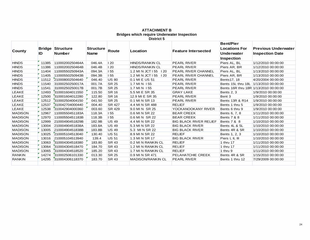
24
ATTACHMENT B Bridges which require Underwater Inspection
District 5
County Bridge ID
Structure Number
Structure Name Route Location Feature Intersected
Bent/Pier Locations For Underwater Inspection
Previous Underwater Inspection Date
HINDS 11385 11000200250464A 046.4A I 20 HINDS/RANKIN CL PEARL RIVER Piers AL, BL 1/12/2010 00:00:00HINDS 11386 11000200250464B 046.4B I 20 HINDS/RANKIN CL PEARL RIVER Piers AR, BR 1/12/2010 00:00:00HINDS 11404 11000550250943A 094.3A I 55 1.2 MI N JCT I 55 I 20 PEARL RIVER CHANNEL Piers AL, BL 1/13/2010 00:00:00HINDS 11405 11000550250943B 094.3B I 55 1.2 MI N JCT I 55 I 20 PEARL RIVER CHANNEL Piers AR, BR 1/13/2010 00:00:00HINDS 11512 210008002504640 046.40 US 80 0.1 MI E US 51 PEARL RIVER Bents17, 18 4/20/2004 00:00:00HINDS 11540 31000250250017A 001.7A SR 25 1.7 MI N I 55 PEARL RIVER Bents 15L thru 18L 1/13/2010 00:00:00HINDS 11541 31000250250017B 001.7B SR 25 1.7 MI N I 55 PEARL RIVER Bents 16R thru 18R 1/13/2010 00:00:00LEAKE 12493 310001604011550 115.50 SR 16 5.5 MI E SR 35 GRAY LAKE Bents 2, 3 1/9/2010 00:00:00LEAKE 12500 310001604012280 122.80 SR 16 12.9 MI E SR 35 PEARL RIVER Bent 3 1/9/2010 00:00:00LEAKE 12512 310002504004150 041.50 SR 25 0.1 MI N SR 13 PEARL RIVER Bents 13R & R14 1/9/2010 00:00:00LEAKE 12537 310042704000440 004.40 SR 427 4.4 MI N SR 488 RELIEF Bents 1 thru 5 1/9/2010 00:00:00LEAKE 12538 310042904000360 003.60 SR 429 9.0 MI N SR 25 YOCKANOOKANY RIVER Bents 6 thru 9 1/9/2010 00:00:00MADISON 12967 11000550451183A 118.3A I 55 0.6 MI N SR 22 BEAR CREEK Bents 6, 7, 8 1/11/2010 00:00:00MADISON 12970 11000550451183B 118.3B I 55 0.6 MI N SR 22 BEAR CREEK Bents 7 & 8 1/11/2010 00:00:00MADISON 12999 21000490451829B 182.9B US 49 4.4 MI N SR 22 BIG BLACK RIVER RELIEF Bents 7 & 8 1/10/2010 00:00:00MADISON 13004 21000490451838A 183.8A US 49 5.3 MI N SR 22 BIG BLACK RIVER Bents 4L & 5L 1/10/2010 00:00:00MADISON 13005 21000490451838B 183.8B US 49 5.3 MI N SR 22 BIG BLACK RIVER Bents 4R & 5R 1/10/2010 00:00:00MADISON 13025 210005104513040 130.40 US 51 8.9 MI N SR 22 RELIEF Bents 1, 2, 3 1/10/2010 00:00:00MADISON 13016 210005104513940 139.4 US 51 1.3 MI N SR 17 BIG BLACK RIVER Piers I, II, III 1/10/2010 00:00:00MADISON 13063 310004304518380 183.80 SR 43 0.2 MI N RANKIN CL RELIEF 1 thru 17 1/11/2010 00:00:00MADISON 13064 310004304518470 184.70 SR 43 1.2 MI N RANKIN CL RELIEF 1 thru 17 1/11/2010 00:00:00MADISON 13065 310004304518520 185.20 SR 43 1.7 MI N RANKIN CL RELIEF 1 thru 9 1/11/2010 00:00:00RANKIN 14274 310002506101330 013.30 SR 25 0.9 MI N SR 471 PELAHATCHIE CREEK Bents 4R & 5R 1/15/2010 00:00:00RANKIN 14295 310004306118370 183.70 SR 43 MADISON/RANKIN CL PEARL RIVER Bents 1 thru 12 7/29/2009 00:00:00

25
ATTACHMENT B Bridges which require Underwater Inspection
District 6
County Bridge ID
Structure Number
Structure Name Route Location Feature Intersected
Bent/Pier Locations For Underwater Inspection
Previous Underwater Inspection Date
CLARKE 10645 11000590121290A 129.0A I 59 3.6 MI N SR 18 RELIEF Bent 3 7/29/2009 00:00:00CLARKE 10648 11000590121290B 129.0B I 59 3.6 MI N SR 18 RELIEF Bents 2 & 3 7/29/2009 00:00:00CLARKE 10679 210004501204540 045.40 SR 18/SR 1450.3 MI N SR 18 W CHICKASAWHAY RIVER Pier 1 6/30/2009 00:00:00CLARKE 10692 310001801216730 167.30 SR 18 1.1 MI E SR 145 ARCHUSA CREEK Bents 2-7 6/30/2009 00:00:00FORREST 10993 11000590180677A 067.7A I 59 0.8 MI N US 49 BOUIE RIVER Pier B & C 12/2/2004 00:00:00FORREST 10994 11000590180677B 067.7B I 59 0.8 MI N US 49 BOUIE RIVER Pier B & C 12/2/2004 00:00:00FORREST 11013 210001101807630 076.30 US 11 0.5 MI S SR 42 EAST LEAF RIVER Bents 2 & 3 7/26/2009 00:00:00FORREST 11020 21000490180493A 049.3A US 49 7.2 MI N SR 13 BLACK CREEK Pier 3 7/27/2009 00:00:00FORREST 11021 21000490180493B 049.3B US 49 7.2 MI N SR 13 BLACK CREEK Peir 2 7/27/2009 00:00:00GEORGE 11117 310002602006520 065.20 SR 26 2.2 MI E SR 57 PASCAGOULA RIVER pier 2-3 142-153 7/22/2009 00:00:00GEORGE 11126 310005702003040 030.40 SR 57 7.7 MI S SR 26 BLACK CREEK Bents 5 & 6 7/23/2009 00:00:00GEORGE 11128 310005702004160 041.60 SR 57 4.2 MI N SR 26 WHISKEY CREEK bents 3-4 7/23/2009 00:00:00GEORGE 11133 310061202000380 003.80 SR 612 3.3 MI W ALA ST LINE ESCATAWPA RIVER bents 4-5 7/23/2009 00:00:00GREENE 11139 21000980211894A 189.4A US 98 2.0 MI E PERRY CL LEAF RIVER bent 18 7/21/2009 00:00:00GREENE 11144 21000980211894B 189.4B US 98 2.0 MI E PERRY CL LEAF RIVER bent 19 7/21/2009 00:00:00GREENE 11157 310004202110790 107.90 SR 42 4.4 MI W SR 57 CHICKASAWHAY RIVER pier B 7/21/2009 00:00:00HANCOCK 11237 110001002300000 000.00 I 10 MISS/LA STATE LINE EAST PEARL RIVER bents 40-41 4/17/2009 00:00:00HANCOCK 15870 110001002301550 015.50 I 10 1.0 MI E SR 43 JOURDAN RIVER bents 4-9 16-24 5/16/2009 00:00:00HANCOCK 16177 210009002301900 19.00 US 90 HANCOCK/HARRISON CL BAY OF ST LOUIS bents 2-68 7/24/2009 00:00:00HANCOCK 11258 310004302300330 003.30 SR 43 2.3 MI S I 10 BAYOU LACROIX bents 2-11 7/25/2009 00:00:00HANCOCK 11259 31000430230033A 003.3A SR 43 2.3 MI S I 10 BAYOU LACROIX bents 2-11 7/25/2009 00:00:00HANCOCK 11260 310004302300760 007.60 SR 43 2.3 MI N I 10 JORDON RIVER bents 3-6 7/26/2009 00:00:00HANCOCK 11268 310060302301530 015.30 SR 603 4.4 MI N SR 43 ORPHAN CREEK bents 2-3 7/26/2009 00:00:00HANCOCK 11269 310060302301770 017.70 SR 603 6.8 MI N SR 43 BAYOU BACON bents 3-5 7/26/2009 00:00:00

26
ATTACHMENT B Bridges which require Underwater Inspection
District 6 (Continued)
County Bridge ID
Structure Number
Structure Name Route Location Feature Intersected
Bent/Pier Locations For Underwater Inspection
Previous Underwater Inspection Date
HANCOCK 11264 310060302302060 020.60 SR 603 4.1 MI S SR 53 CYPRESS CREEK bents 2-3 7/26/2009 00:00:00HARRISON 11285 11000100240407A 040.7A I 10 2.5 MI W SR 67 BILOXI RIVER bent 5 piers 1-2 6/28/2009 00:00:00HARRISON 11286 11000100240407B 040.7B I 10 2.5 MI W SR 67 BILOXI RIVER bent 5 piers 1-2 6/28/2009 00:00:00HARRISON 11304 11000100240450A 045.0A I 10 1.6 MI E SR 67 TCHOUTACABOUFFA RIVERbents8,9,21 piers1-2 6/23/2009 00:00:00HARRISON 11305 11000100240450B 045.0B I 10 1.6 MI E SR 67 TCHOUTACABOUFFA RIVERbents9,10,21 piers 1-2 6/23/2009 00:00:00HARRISON 11316 110011002400010 000.10 I 110 0.1 MI N US 90 L&N RR AND KEEGAN BAYObents37-38 6/28/2009 00:00:00HARRISON 15509 110011002400130 001.30 I 110 1.3 MI N US 90 BILOXI BACK BAY bents 11-49 5/13/2009 00:00:00HARRISON 15523 17001100240012A 001.2A I 110 RAMP 1.2 MI N US 90 BILOXI BACK BAY bents 7-8 5/12/2009 00:00:00HARRISON 15524 17001100240012B 001.2B I 110 RAMP 1.2 MI N US 90 BILOXI BACK BAY bents 8-9 5/12/2009 00:00:00HARRISON 11324 21000490240080A 008.0A US 49 3.2 MI N I 10 FLAT BRANCH bent 4 5/12/1999 00:00:00HARRISON 16178 21000900240494A 049.4A US 90 2.2 MI E I 110 BILOXI BAY bents 4-68 4/16/2009 00:00:00HARRISON 16179 21000900240494B 049.4B US 90 2.2 MI E I 110 BILOXI BAY bents 4-68 4/19/2009 00:00:00HARRISON 11337 31000150240046A 004.6A SR 15 0.5 MI N I 10 TCHUTACABOUFFA RIVER bents 7-10 5/4/1999 00:00:00HARRISON 11338 31000150240046B 004.6B SR 15 0.5 MI N I 10 TCHUTACABOUFFA RIVER bents 7-11 5/4/1999 00:00:00HARRISON 15662 310060502400160 001.60 SR 605 1.6 MI N US 90 BERNARD BAYOU bents 6-11 5/15/2001 00:00:00JACKSON 11794 11000100300590A 59.0A I 10 0.3 MI W OF SR 57 OLD FORT BAYOU BENTS 4-5 1/1/1901 00:00:00JACKSON 11795 11000100300590B 59.0B I 10 0.3 MI W OF SR 57 OLD FORT BAYOU BENTS 4-5 1/1/1901 00:00:00JACKSON 11800 11000100300654A 065.4A I 10 4.4 MI W SR 613 PASCAGOULA RIVER bents 4-305 4/21/2009 00:00:00JACKSON 11801 11000100300654B 065.4B I 10 4.4 MI W SR 613 PASCAGOULA RIVER bents 3-13, 16-305 4/23/2009 00:00:00JACKSON 11810 11000100300741A 074.1A I 10 3.4 MI E SR 63 BLACK CREEK bents 13-14 6/25/2009 00:00:00JACKSON 11811 11000100300741B 074.1B I 10 3.4 MI E SR 63 BLACK CREEK bents 11-14 6/26/2009 00:00:00JACKSON 11812 11000100300755A 075.5A I 10 4.8 MI E SR 63 ESCATAWPA RIVER bents 9-11 1/8/2010 00:00:00JACKSON 11813 11000100300755B 075.5B I 10 4.8 MI E SR 63 ESCATAWPA RIVER bents 9-10 6/27/2009 00:00:00JACKSON 15760 210009003006560 065.60 US 90 6.6 MI E SR 57 WEST PASCAGOULA RIVERbents 5-36 5/15/2009 00:00:00JACKSON 15820 210009003006830 068.30 US 90 0.9 MI W SR 613 EAST PASCAGOULA RIVER bents 12-18 6/26/2009 00:00:00
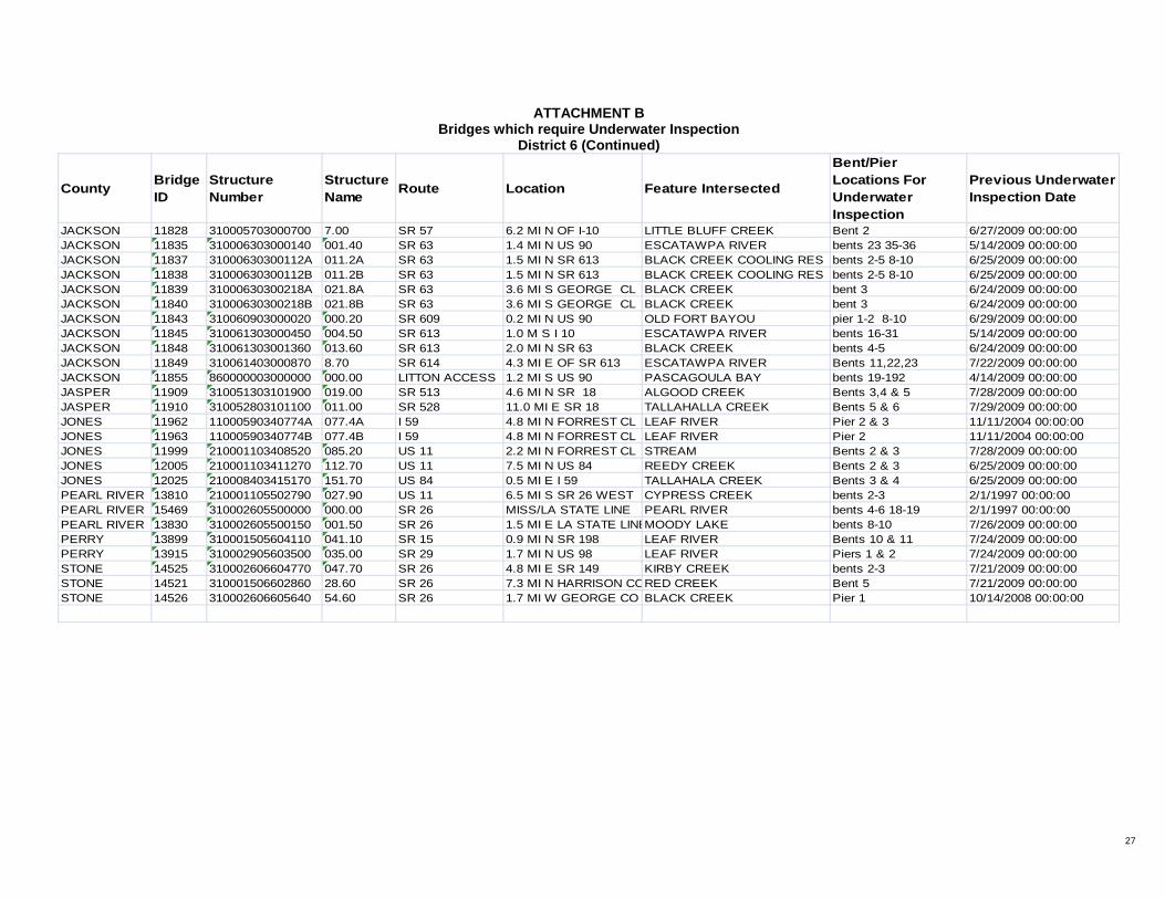
27
ATTACHMENT B Bridges which require Underwater Inspection
District 6 (Continued)
County Bridge ID
Structure Number
Structure Name Route Location Feature Intersected
Bent/Pier Locations For Underwater Inspection
Previous Underwater Inspection Date
JACKSON 11828 310005703000700 7.00 SR 57 6.2 MI N OF I-10 LITTLE BLUFF CREEK Bent 2 6/27/2009 00:00:00JACKSON 11835 310006303000140 001.40 SR 63 1.4 MI N US 90 ESCATAWPA RIVER bents 23 35-36 5/14/2009 00:00:00JACKSON 11837 31000630300112A 011.2A SR 63 1.5 MI N SR 613 BLACK CREEK COOLING RES bents 2-5 8-10 6/25/2009 00:00:00JACKSON 11838 31000630300112B 011.2B SR 63 1.5 MI N SR 613 BLACK CREEK COOLING RES bents 2-5 8-10 6/25/2009 00:00:00JACKSON 11839 31000630300218A 021.8A SR 63 3.6 MI S GEORGE CL BLACK CREEK bent 3 6/24/2009 00:00:00JACKSON 11840 31000630300218B 021.8B SR 63 3.6 MI S GEORGE CL BLACK CREEK bent 3 6/24/2009 00:00:00JACKSON 11843 310060903000020 000.20 SR 609 0.2 MI N US 90 OLD FORT BAYOU pier 1-2 8-10 6/29/2009 00:00:00JACKSON 11845 310061303000450 004.50 SR 613 1.0 M S I 10 ESCATAWPA RIVER bents 16-31 5/14/2009 00:00:00JACKSON 11848 310061303001360 013.60 SR 613 2.0 MI N SR 63 BLACK CREEK bents 4-5 6/24/2009 00:00:00JACKSON 11849 310061403000870 8.70 SR 614 4.3 MI E OF SR 613 ESCATAWPA RIVER Bents 11,22,23 7/22/2009 00:00:00JACKSON 11855 860000003000000 000.00 LITTON ACCESS 1.2 MI S US 90 PASCAGOULA BAY bents 19-192 4/14/2009 00:00:00JASPER 11909 310051303101900 019.00 SR 513 4.6 MI N SR 18 ALGOOD CREEK Bents 3,4 & 5 7/28/2009 00:00:00JASPER 11910 310052803101100 011.00 SR 528 11.0 MI E SR 18 TALLAHALLA CREEK Bents 5 & 6 7/29/2009 00:00:00JONES 11962 11000590340774A 077.4A I 59 4.8 MI N FORREST CL LEAF RIVER Pier 2 & 3 11/11/2004 00:00:00JONES 11963 11000590340774B 077.4B I 59 4.8 MI N FORREST CL LEAF RIVER Pier 2 11/11/2004 00:00:00JONES 11999 210001103408520 085.20 US 11 2.2 MI N FORREST CL STREAM Bents 2 & 3 7/28/2009 00:00:00JONES 12005 210001103411270 112.70 US 11 7.5 MI N US 84 REEDY CREEK Bents 2 & 3 6/25/2009 00:00:00JONES 12025 210008403415170 151.70 US 84 0.5 MI E I 59 TALLAHALA CREEK Bents 3 & 4 6/25/2009 00:00:00PEARL RIVER 13810 210001105502790 027.90 US 11 6.5 MI S SR 26 WEST CYPRESS CREEK bents 2-3 2/1/1997 00:00:00PEARL RIVER 15469 310002605500000 000.00 SR 26 MISS/LA STATE LINE PEARL RIVER bents 4-6 18-19 2/1/1997 00:00:00PEARL RIVER 13830 310002605500150 001.50 SR 26 1.5 MI E LA STATE LINEMOODY LAKE bents 8-10 7/26/2009 00:00:00PERRY 13899 310001505604110 041.10 SR 15 0.9 MI N SR 198 LEAF RIVER Bents 10 & 11 7/24/2009 00:00:00PERRY 13915 310002905603500 035.00 SR 29 1.7 MI N US 98 LEAF RIVER Piers 1 & 2 7/24/2009 00:00:00STONE 14525 310002606604770 047.70 SR 26 4.8 MI E SR 149 KIRBY CREEK bents 2-3 7/21/2009 00:00:00STONE 14521 310001506602860 28.60 SR 26 7.3 MI N HARRISON CORED CREEK Bent 5 7/21/2009 00:00:00STONE 14526 310002606605640 54.60 SR 26 1.7 MI W GEORGE CO BLACK CREEK Pier 1 10/14/2008 00:00:00

28
ATTACHMENT B Bridges which require Underwater Inspection
District 7
County Bridge ID
Structure Number
Structure Name Route Location Feature Intersected
Bent/Pier Locations For Underwater Inspection
Previous Underwater Inspection Date
ADAMS 10018 21000840010001A 000.1A US 84 MISS/LA STATE LINE MISSISSIPPI RIVER piers 1,2,&3 12/16/2009 00:00:00ADAMS 10019 21000840010001B 000.1B US 84 MISS/LA STATE LINE MISSISSIPPI RIVER piers 1,2,&3 12/16/2009 00:00:00AMITE 10111 310002400305590 055.90 SR 24 0.1 MI E SR 567 NORTH TANYARD CREEK BENTS 2 & 3 8/29/2009 00:00:00AMITE 10128 310004800300440 004.40 SR 48 4.2 MI E SR 24 RELIEF bents 2, 3, 4 8/29/2009 00:00:00AMITE 10131 310004800300460 004.60 SR 48 4.4 MI E SR 24 RELIEF bents 3 thru 8 8/29/2009 00:00:00AMITE 10137 310056700300600 006.00 SR 567 6.0 MI N SR 24 WEST FORK AMITE RIVER bents 3, 4 8/29/2009 00:00:00AMITE 10143 310057000300660 006.60 SR 570 1.1 MI E SR 569 EAST FORK AMITE RIVER bents 3, 4 8/30/2009 00:00:00AMITE 10159 310057000301170 011.70 SR 570 0.9 MI W PIKE CL TANGIPAHOA RIVER bents 6, 7, 8 8/30/2009 00:00:00AMITE 10160 310057100300000 000.00 SR 571 0.1 MI N LA STATE LINE UNNAMED STREAM bents 1, 2 8/28/2009 00:00:00AMITE 10163 310058400300710 007.10 SR 584 6.8 MI E SR 24 EAST FORK AMITE RIVER bents 3 thru 6 8/27/2009 00:00:00AMITE 10149 310058400300730 007.30 SR 584 7.1 MI E SR 24 RELIEF bents 4 thru 8 8/28/2009 00:00:00AMITE 10150 310058400300750 007.50 SR 584 7.2 MI E SR 24 RELIEF bents 5, 6 8/28/2009 00:00:00COVINGTON 10892 310003501605120 051.20 SR 35 0.5 MI N JEFF DAVIS CL BOWIE RIVER bents 3, 4 6/24/2009 00:00:00COVINGTON 10908 310058901602940 029.40 SR 589 3.1 MI N LAMAR CL BOWIE RIVER bents 5, 6 6/24/2009 00:00:00COVINGTON 10906 310059001600390 003.90 SR 590 3.9 MI E US 49 CURREY CREEK bents 3, 4 4/21/2004 00:00:00JEFF DAVIS 11953 310004203301800 018.00 SR 42 0.1 MI E US 84 WHITE SAND TRIB bents 2 thru 5 6/24/2009 00:00:00JEFF DAVIS 11955 310004203301820 018.20 SR 42 0.4 MI E US 84 WHITE SAND CREEK bents 14, 15, 16 6/26/2009 00:00:00JEFF DAVIS 11960 310054103300620 006.20 SR 541 4.7 MI S SIMPSON CL BOWIE CREEK bents 3, 4, 5 8/27/2009 00:00:00LAWRENCE 12459 210008403908640 086.40 SR 184 2.4 MI E SR 27 PEARL RIVER piers 2 & 3 6/17/2004 00:00:00LINCOLN 12833 210009804306330 063.30 US 98 10.2 MI W I 55 EAST FORK AMITE RIVER bents 4, 5 8/27/2009 00:00:00LINCOLN 12834 210009804306340 063.40 US 98 10.1 MI W I 55 RELIEF bent 2 8/27/2009 00:00:00LINCOLN 12835 210009804306350 063.50 US 98 10.0 MI W I 55 ADAMS CREEK bent 2 6/23/2009 00:00:00LINCOLN 12840 310055004302130 021.30 SR 550 1.8 MI W US 51 BOGUE CHITTO RIVER bents 2 , 3 6/23/2009 00:00:00LINCOLN 12843 310058304302040 020.40 SR 583 2.1 MI N LAWRENCE CL TOPISAW CREEK bents 3 thru 6 6/23/2009 00:00:00

29
ATTACHMENT B Bridges which require Underwater Inspection
District 7 (Continued)
County Bridge ID
Structure Number
Structure Name Route Location Feature Intersected
Bent/Pier Locations For Underwater Inspection
Previous Underwater Inspection Date
MARION 13084 21000980461185A 118.5A US 98 0.6 MI E SR 35 NORTH PEARL RIVER bents 4, 5, 6 8/25/2009 00:00:00MARION 13095 21000980461185B 118.5B US 98 0.6 MI E SR 35 NORTH PEARL RIVER bents 4 thru 7 8/25/2009 00:00:00MARION 13114 310003504601940 019.40 SR 35 2.0 MI N US 98 PEARL RIVER piers 1, 2 & bent 6 3/24/2008 00:00:00MARION 13118 310003504602530 025.30 SR 35 3.0 MI N SR 13 HARPERS CREEK bents 2, 3, 4 8/26/2009 00:00:00PIKE 13932 11000550570084A 008.4A I 55 0.6 MI N SR 568 TANGIPAHOA RIVER bents 4, 5 8/26/2009 00:00:00PIKE 13924 11000550570084B 008.4B I 55 0.6 MI N SR 568 TANGIPAHOA RIVER bents 4, 5 6/26/2009 00:00:00PIKE 13940 210005105700830 008.30 US 51 0.4 MI N SR 568 TANGIPAHOA RELIEF bents 2, 3, 4 6/26/2009 00:00:00PIKE 13950 210005105702470 024.70 US 51 1.9 MI N US 98 WEST LAKE DIXIE SPRINGS bents 1 thru 4 6/26/2009 00:00:00PIKE 13963 310004405700510 005.10 SR 44 5.1 MI E US 51 BOGUE CHITTO RIVER bents 4, 5, 6 6/27/2009 00:00:00PIKE 13966 310004405700910 009.10 SR 44 9.1 MI E US 51 TOPISAW CREEK bent 3 6/27/2009 00:00:00PIKE 13981 310057005702510 025.10 SR 570 6.3 MI N SR 44 BOGUE CHITTO RIVER bents 4, 5 8/25/2009 00:00:00SIMPSON 14427 21000490641283A 128.3A US 49 1.0 MI N SR 13 STRONG RIVER pier AL 6/27/2009 00:00:00SIMPSON 14428 21000490641283B 128.3B US 49 1.0 MI N SR 13 STRONG RIVER pier AR 6/27/2009 00:00:00SIMPSON 14447 310002806407360 073.60 SR 28 8.9 MI E COPIAH CL STRONG RIVER pier 2 6/24/2009 00:00:00WALTHALL 14869 310002707402160 021.60 SR 27 4.9 MI S LAWRENCE CL RAVEN CREEK bent 2, 3 6/26/2009 00:00:00WALTHALL 14871 310002707402520 025.20 SR 27 1.3 MI S LAWRENCE CL MAGEE CREEK bent 2, 3 8/27/2009 00:00:00WALTHALL 14883 310004807405490 054.90 SR 48 0.5 MI E PIKE CL BOGUE CHITTO RIVER bents 3, 4 6/17/2004 00:00:00WALTHALL 14893 310058507400380 003.80 SR 585 3.8 MI N US 98 UNNAMED STREAM bents 2, 3, 4 8/27/2009 00:00:00WALTHALL 14894 310058507400780 007.80 SR 585 7.8 MI N US 98 DARBUN CREEK bents 2, 3 8/27/2009 00:00:00

30
ATTACHMENT C (Substitute new attachment with new contract)
Bridges which require Sonar Inspection
County Bridge ID Structure Number
Structure Name Route Feature
Intersected
Bent/Pier Locations For Sonar Inspection
HANCOCK 11237 1100010023000000 000.00 I-10 Pearl River BENTS 40, 41ADAMS 10018 21000840010001A 000.1A US 84 Mississippi River PIERS 1, 2, 3ADAMS 10019 21000840010001B 000.1B US 84 Mississippi River PIERS 1, 2, 3LOWNDES 12869 21000450441608B 160.8B US 45 Tenn-Tom Waterway BENT 7RCLAY 10750 310005001303340 033.40 SR 50 Tenn-Tom Waterway BENT 12
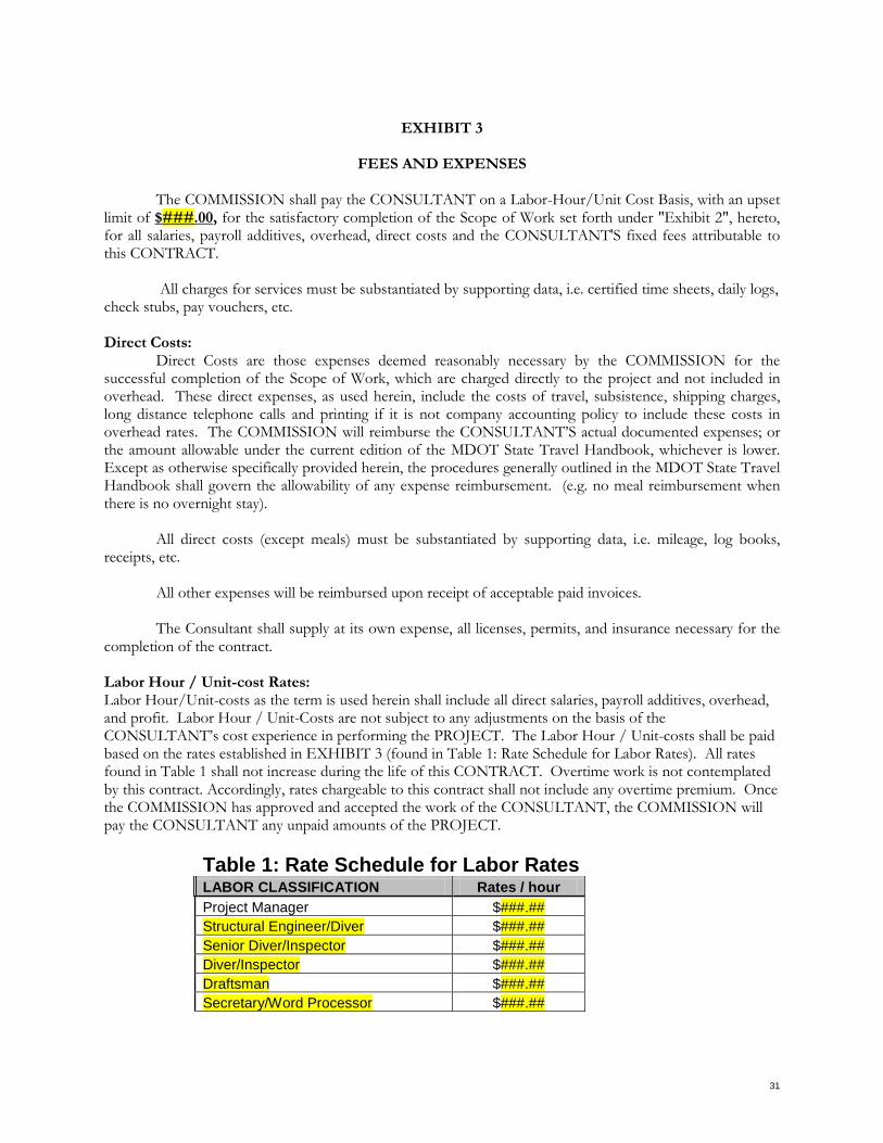
31
EXHIBIT 3
FEES AND EXPENSES The COMMISSION shall pay the CONSULTANT on a Labor-Hour/Unit Cost Basis, with an upset limit of $###.00, for the satisfactory completion of the Scope of Work set forth under "Exhibit 2", hereto, for all salaries, payroll additives, overhead, direct costs and the CONSULTANT'S fixed fees attributable to this CONTRACT.
All charges for services must be substantiated by supporting data, i.e. certified time sheets, daily logs, check stubs, pay vouchers, etc. Direct Costs: Direct Costs are those expenses deemed reasonably necessary by the COMMISSION for the successful completion of the Scope of Work, which are charged directly to the project and not included in overhead. These direct expenses, as used herein, include the costs of travel, subsistence, shipping charges, long distance telephone calls and printing if it is not company accounting policy to include these costs in overhead rates. The COMMISSION will reimburse the CONSULTANT’S actual documented expenses; or the amount allowable under the current edition of the MDOT State Travel Handbook, whichever is lower. Except as otherwise specifically provided herein, the procedures generally outlined in the MDOT State Travel Handbook shall govern the allowability of any expense reimbursement. (e.g. no meal reimbursement when there is no overnight stay).
All direct costs (except meals) must be substantiated by supporting data, i.e. mileage, log books, receipts, etc. All other expenses will be reimbursed upon receipt of acceptable paid invoices. The Consultant shall supply at its own expense, all licenses, permits, and insurance necessary for the completion of the contract. Labor Hour / Unit-cost Rates: Labor Hour/Unit-costs as the term is used herein shall include all direct salaries, payroll additives, overhead, and profit. Labor Hour / Unit-Costs are not subject to any adjustments on the basis of the CONSULTANT’s cost experience in performing the PROJECT. The Labor Hour / Unit-costs shall be paid based on the rates established in EXHIBIT 3 (found in Table 1: Rate Schedule for Labor Rates). All rates found in Table 1 shall not increase during the life of this CONTRACT. Overtime work is not contemplated by this contract. Accordingly, rates chargeable to this contract shall not include any overtime premium. Once the COMMISSION has approved and accepted the work of the CONSULTANT, the COMMISSION will pay the CONSULTANT any unpaid amounts of the PROJECT.
Table 1: Rate Schedule for Labor Rates LABOR CLASSIFICATION Rates / hour Project Manager $###.## Structural Engineer/Diver $###.## Senior Diver/Inspector $###.## Diver/Inspector $###.## Draftsman $###.## Secretary/Word Processor $###.##

32
SCHEDULE OF MAXIMUM RATES, EXPENSES & FEES:
The Rate Schedule for Labor Rates shall not be exceeded for all work under this CONTRACT: Contract Maximums:
Under no circumstances shall the amount payable by the COMMISSION for this assignment exceed $###.00 (Total of all Charges) without the prior written consent of both parties
NOTE: The delineation of the Labor-Hour/Unit Costs is attached behind Exhibit 9.

33
EXHIBIT 4
SAMPLE INVOICE
[Labor-Hour/Unit Cost] MISSISSIPPI DEPARTMENT OF TRANSPORTATION P. O. BOX 1850 JACKSON, MS 39215-1850 DATE: ATTENTION: XXX, Consultant Services Administrator INVOICE NO. 0000 PERIOD _____, 20__ THROUGH ____, 20__ PROFESSIONAL SERVICES IN ACCORDANCE WITH CONTRACT DATED______________________________, 20__, AS RELATES TO PROJECT NO. ___-___-____-____-____ IN___________ COUNTY, HIGHWAY______. CONSULTANT: CUSTOMER NUMBER 0000000000 FILE NO. 000-000000 REPORT NUMBER: 0000 through 00000 CURRENT PREVIOUS TOTAL ALLOWED PERIOD ESTIMATE TO DATE * DIRECT SALARIES $ $ $ ** DIRECT COSTS $ $ $ PROJECT TOTAL $ $ $ AMOUNT DUE THIS INVOICE: $ NOTE: 1. * ATTACH SUPPORTING DATA 2. ** DIRECT COSTS (ATTACH SUPPORTING DATA) 3. THE CONSULTANT MAY USE ITS OWN INVOICE FORM SO LONG AS IT HAS BEEN
APPROVED. PRIOR TO SUBMISSION BY THE CONSULTANT SAID FORM SHOULD, AT A MINIMUM, CONTAIN THE ABOVE INFORMATION

34
SUPPORTING DATA Project No. 00-0000-00-000-00 County _______________ Rate Current Previous Costs Employee and of Pay Period Period To Classification (in contract) Hours Costs Date DIRECT LABOR AND DIRECT COSTS John P. Public, Jr 0.00 0.00 0.00 0.00 Engineer John P. Public, Jr 0.00 0.000 0.00 0.00 Designer John P. Public, Jr 0.00 0.00 0.00 0.00 Engineer John P. Public, Jr 0.00 0.00 0.00 0.00 Technician Sub Total 0.00 0.00 0.00 Total Labor 0.00 0.00 Direct Costs 0.00 0.00 Project Total 0.00 0.00

35
EXHIBIT 5
NOTICE TO CONTRACTORS, FEDERAL AID CONTRACT COMPLIANCE WITH TITLE VI OF THE CIVIL RIGHTS ACT OF 1964 COPELAND ANTI-KICKBACK ACT DAVIS BACON ACT CONTRACT WORK HOURS AND SAFETY STANDARDS ACT CLEAN AIR ACT ENERGY POLICY AND CONSERVATION ACT
DISADVANTAGED BUSINESS ENTERPRISES ACT WORKER VISIBILITY
During the performance of this CONTRACT, the CONSULTANT, for itself, its assignees and successor-in-interest (hereinafter referred to as the "CONSULTANT") agrees as follows: 1. Compliance with Regulations: The CONSULTANT will comply with the Regulations of the COMMISSION, relative to nondiscrimination in Federally-assisted programs of the U. S. Department of Transportation (Title 49, Code of Federal Regulations, Part 21, hereinafter referred to as the "Regulations"), which are herein incorporated by reference and made a part of this CONTRACT. 2. Nondiscrimination: The CONSULTANT, with regard to the work performed by it after award and prior to completion of the contract work, will not discriminate on the grounds of race, religion, color, sex, national origin, age or disability in the selection and retention of subconsultants including procurement of materials and leases of equipment. The CONSULTANT will not participate either directly or indirectly in the discrimination prohibited by Section 21.5 of the Regulations, including employment practices when this CONTRACT covers a program set forth in Appendix B of the Regulations. In addition, the CONSULTANT will not participate either directly or indirectly in discrimination prohibited by 23 C.F.R. 710.405(b). 3. Solicitations for Subcontracts. Including Procurement of Materials and Equipment: In all Solicitations, either by competitive bidding or negotiation made by the CONSULTANT for work to be performed under a subcontract, including procurement of materials or equipment, each potential subconsultant or supplier shall be notified by the CONSULTANT of the CONSULTANT'S obligations under this CONTRACT and the Regulations relative to nondiscrimination on the grounds of race, religion, color, sex, national origin, age or disability. 4. Anti-kick back provisions: All CONTRACTS and subcontracts for construction or repair shall include a provision for compliance with the Copeland "Anti-Kick Back" Act (18 U.S.C. 874) as supplemented in Department of Labor regulations (29 CFR, Part 3). This Act provides that each CONSULTANT or subconsultant shall be prohibited from inducing, by any means, any person employed in the construction, completion, or repair of public work, to give up any part of the compensation to which he is otherwise entitled. The CONSULTANT shall report all suspected or reported violations to the COMMISSION. 5. Davis Bacon Act: When required by the federal grant program legislation, all construction contracts awarded to contractors and subcontractors in excess of $2,000 shall include a provision for compliance with the Davis-Bacon Act (40 U.S.C. 276a to a-7) and as supplemented by Department of Labor regulations (29 CFR, Part 5). Under this Act, contractors shall be required to pay wages to laborers and mechanics at a rate not less than the minimum wages specified in a wage determination made by the Secretary of Labor. In addition, contractors shall be required to pay wages specified in a wage determination made by the Secretary of Labor. In addition, contractors shall be required to pay wages specified in a wage determination made by the Secretary of Labor. In addition, contractors shall be required to pay wages not less often than once a week.

36
6. Contract Work Hours and Safety Standards Act: Where applicable, all contracts awarded by contractors and subcontractors in excess of $2,000 for construction contracts and in excess of $2,500 for other contracts which involve the employment of mechanics or laborers shall include a provision for compliance with sections 103 and 107 of the Contract Work Hours and Safety Standards Act (40 U.S.C. 327-330) as supplemented by Department of Labor Regulations (29 CFR, Part 5). Under section 103 of the Act, each contractor shall be required to compute the wages of every mechanic and laborer on the basis of a standard work week of 40 hours. Work in excess of the standard work week is permissible provided that the worker is compensated at a rate of not less than 1 1/2 times the basic rate of pay for all hours worked in excess of 40 hours in the work week. Section 107 of the Act is applicable to construction work and provides that no laborer or mechanic shall be required to work in surroundings or under working conditions which are unsanitary, hazardous, or dangerous to his health and safety as determined under construction, safety, and health standards promulgated by the Secretary of Labor. These requirements do not apply to the purchases of supplies or materials or articles ordinarily available on the open market, or contracts for transportation or transmission of intelligence. 7. Clean Air Act: Compliance with all applicable standards, orders, or requirements issued under section 306 of the Clear Air Act (42 U.S.C. 1857 (h), Section 508 of the Clean Water Act (33 U.S.C. 1368), Executive Order 11738, and Environmental Protection Agency regulations (40 CFR Part 15) (Contracts and subcontracts in amounts in excess of $100,000). 8. Energy Policy and Conservation Act: Mandatory standards and policies relating to energy efficiency which are contained in the state energy conservation plan issued in compliance with the Energy Policy and Conservation Act (Pub. L. 94-163). 9. Disadvantaged Business Enterprises (DBE): It is the policy of the MDOT to comply with the requirements of 49 C.F.R. 26, to prohibit unlawful discrimination, to meet it’s goal for DBE participation, to meet that goal whenever possible by race-neutral means, to create a level playing field, and to achieve that amount of DBE participation that would be obtained in an non-discriminatory market place. To meet that objective in any United States Department of Transportation assisted contracts, the COMMISSION and the CONSULTANT shall comply with the “Mississippi Department of Transportation’s Disadvantage Business Enterprise Programs For United States Department Of Transportation Assisted Contracts”.
Neither the CONSULTANT, nor any sub-recipient or sub-consultant shall discriminate on the bases of race, color, national origin, or sex in the performance of this CONTRACT. The CONSULTANT shall carry out applicable requirements of 49 C.F.R. 26 in the award and administration of United States Department of Transportation assisted contracts. Failure of the CONSULTANT to carry out those requirements is a material breach of this CONTRACT which may result in the termination of this CONTRACT or such other remedies as the MDOT deems appropriate. 10. Worker Visibility: All workers within the right-of-way of a Federal-aid highway who are exposed either to traffic (vehicles using the highway for the purposes of travel) or to construction equipment within the work area shall wear high-visibility safety apparel – personal protective safety clothing that is intended to provide conspicuity during both daytime and nighttime usage, and that meets the Performance Class 2 or 3 requirements of the ANSI/ISEA 107–2004 publication entitled ‘‘American National Standard for High-Visibility Safety Apparel and Headwear” – for compliance with 23 CFR, Part 634.

37
EXHIBIT 6 CERTIFICATION REGARDING DEBARMENT, SUSPENSION AND OTHER RESPONSIBILITY MATTERS CERTIFICATION REGARDING DEBARMENT, SUSPENSION, AND OTHER RESPONSIBILITY MATTERS - Certification in accordance with Section 29.510 Appendix A, C.F.R./Vol. 53, No. 102, page 19210 and 19211: (1) The CONSULTANT certifies to the best of its knowledge and belief that it and its principals: (a) are not presently debarred, suspended, proposed for debarment, declared ineligible, or voluntarily excluded from covered transactions by any federal department or agency; (b) have not within a three-year period preceding this proposal been convicted of or had a
civil judgment rendered against them for commission of fraud or a criminal offense in connection with obtaining, attempting to obtain, or performing a public (federal, state or local) transaction or CONTRACT under a public transaction, violation of federal or state antitrust statutes or commission of embezzlement, theft, forgery, bribery, falsification or destruction of records, making false statements, or receiving stolen property;
(c) are not presently indicted for or otherwise criminally or civilly charged by a
governmental entity (federal, state or local) with commission of any of the offenses enumerated in paragraph (l)(b) of this certification: and
(d) have not within a three-year period preceding this application/proposal had one or
more public transactions (federal, state or local) terminated for cause or default; (e) has not either directly or indirectly entered into any agreement participated in any
collusion; or otherwise taken any action in restraint of free competitive negotiation in connection with this CONTRACT.
(2) The CONSULTANT further certifies, to the best of his/her knowledge and belief, that: (f) No federal appropriated funds have been paid or will be paid to any person for
influencing or attempting to influence an officer or employee of any Federal agency, a member of Congress, an officer or employee of Congress, or employee of a member of Congress in connection with the awarding of any Federal loan, the entering into of any cooperative agreement, and the extension, continuation, renewal, amendment, or modification of any Federal contract, grant, loan, or cooperative agreement.
(g) If any funds other than Federal appropriated funds have been paid or will be paid to
any person for influencing or attempting to influence an officer of employee of Congress, or any employee of a member of Congress in connection with this CONTRACT, Standard Form-LLL,"Disclosure Form to Report Lobbying", in accordance with its instructions will be completed and submitted.
The certification contained in (1) and (2) above is a material representation of fact upon which reliance is placed and a pre-requisite imposed by Section 1352, Title 31, U. S. Code prior to entering into this CONTRACT. Failure to comply shall be subject to a civil penalty of not less than $10,000 and not more than $100,000. The CONSULTANT shall include the language of the certification in all subcontracts exceeding $25,000 and all sub-consultants shall certify and disclose accordingly.

38
I hereby certify that I am the duly authorized representative of the CONSULTANT for purposes of making this certification, and that neither I, nor any principal, officer, shareholder or employee of the above firm has: (a) employed or retained for commission, percentages, brokerage, contingent fee, or
other consideration, any firm or person (other than a bona fide employee working solely for me or the above CONSULTANT) to solicit or secure this agreement,
(b) agreed, as an express or implied condition for obtaining this CONTRACT, to employ
or retain the services of any firm or person in connection with carrying out the agreement, or (c) paid, or agreed to pay, to any firm, organization or person (other than a bone fide
employee working solely for me or the above CONSULTANT) any fee, contribution, donation, or consideration of any kind for, or in connection with, procuring or carrying out the agreement; except as herein expressly stated (if any).
I acknowledge that this Agreement may be furnished to the Federal Highway Administration, United States Department of Transportation, in connection with the Agreement involving participation of Federal-Aid Highway funds, and is subject to applicable state and federal laws, both criminal and civil. SO CERTIFIED this______ day of ___________________, 2009. CCCXXX _________________________________ ATTEST: ______________________ My Commission Expires: _________________________ Notary
39
EXHIBIT 7 CERTIFICATION OF MISSISSIPPI TRANSPORTATION COMMISSION I hereby certify that I am the Executive Director of the Mississippi Department of Transportation, duly authorized by the Mississippi Transportation Commission to execute this certification and that the above consulting firm or its representative has not been required, directly or indirectly, as an express or implied condition in connection with obtaining or carrying out this agreement to: (a) employ or retain, or agree to employ or retain, firm or person, or (b) pay, or agree to pay, to any firm, person organization, any fee, contribution, donation,
or consideration of any kind except as here expressly stated (if any). SO CERTIFIED on the_______ day of ________________, 2009. THE MISSISSIPPI TRANSPORTATION COMMISSION BY AND THROUGH THE EXECUTIVE DIRECTOR OF THE MISSISSIPPI TRANSPORTATION DEPARTMENT _____________________________________________ XXX, EXECUTIVE DIRECTOR

40
EXHIBIT 8
{Intentionally Left Blank}
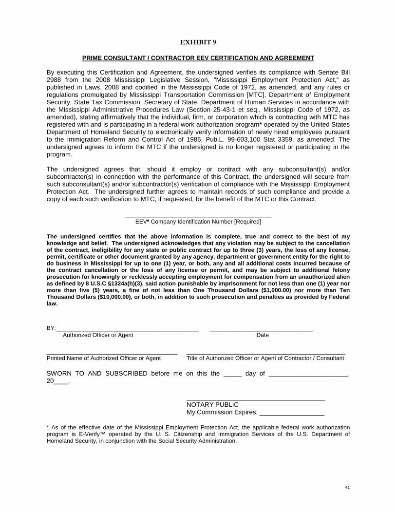
41
EXHIBIT 9
PRIME CONSULTANT / CONTRACTOR EEV CERTIFICATION AND AGREEMENT
By executing this Certification and Agreement, the undersigned verifies its compliance with Senate Bill 2988 from the 2008 Mississippi Legislative Session, "Mississippi Employment Protection Act," as published in Laws, 2008 and codified in the Mississippi Code of 1972, as amended, and any rules or regulations promulgated by Mississippi Transportation Commission [MTC], Department of Employment Security, State Tax Commission, Secretary of State, Department of Human Services in accordance with the Mississippi Administrative Procedures Law (Section 25-43-1 et seq., Mississippi Code of 1972, as amended), stating affirmatively that the individual, firm, or corporation which is contracting with MTC has registered with and is participating in a federal work authorization program* operated by the United States Department of Homeland Security to electronically verify information of newly hired employees pursuant to the Immigration Reform and Control Act of 1986, Pub.L. 99-603,100 Stat 3359, as amended. The undersigned agrees to inform the MTC if the undersigned is no longer registered or participating in the program. The undersigned agrees that, should it employ or contract with any subconsultant(s) and/or subcontractor(s) in connection with the performance of this Contract, the undersigned will secure from such subconsultant(s) and/or subcontractor(s) verification of compliance with the Mississippi Employment Protection Act. The undersigned further agrees to maintain records of such compliance and provide a copy of each such verification to MTC, if requested, for the benefit of the MTC or this Contract.
_____________________________________ EEV* Company Identification Number [Required]
The undersigned certifies that the above information is complete, true and correct to the best of my knowledge and belief. The undersigned acknowledges that any violation may be subject to the cancellation of the contract, ineligibility for any state or public contract for up to three (3) years, the loss of any license, permit, certificate or other document granted by any agency, department or government entity for the right to do business in Mississippi for up to one (1) year, or both, any and all additional costs incurred because of the contract cancellation or the loss of any license or permit, and may be subject to additional felony prosecution for knowingly or recklessly accepting employment for compensation from an unauthorized alien as defined by 8 U.S.C §1324a(h)(3), said action punishable by imprisonment for not less than one (1) year nor more than five (5) years, a fine of not less than One Thousand Dollars ($1,000.00) nor more than Ten Thousand Dollars ($10,000.00), or both, in addition to such prosecution and penalties as provided by Federal law. BY:____________________________________ __________________________ Authorized Officer or Agent Date _________________________________ ________________________________________ Printed Name of Authorized Officer or Agent Title of Authorized Officer or Agent of Contractor / Consultant SWORN TO AND SUBSCRIBED before me on this the _____ day of ______________________, 20____.
___________________________________ NOTARY PUBLIC My Commission Expires: __________________
* As of the effective date of the Mississippi Employment Protection Act, the applicable federal work authorization program is E-Verify™ operated by the U. S. Citizenship and Immigration Services of the U.S. Department of Homeland Security, in conjunction with the Social Security Administration.

42
Cost Estimate for Labor Hour/Lump Sum Contract
PROFIT 12%
Classification Hours Hourly Wage Overhead %
(from contract) Overhead Costs Profit Costs Total Labor Rate Total Labor cost
Principle ##.## ##.## ##.## ##.## ##.## ##.## ##.##
Project Manager ##.## ##.## ##.## ##.## ##.## ##.## ##.##
Structural Engineer/Diver ##.## ##.## ##.## ##.## ##.## ##.## ##.##
Senior Diver/inspector ##.## ##.## ##.## ##.## ##.## ##.## ##.##
Diver/Inspector ##.## ##.## ##.## ##.## ##.## ##.## ##.##
Draftsman ##.## ##.## ##.## ##.## ##.## ##.## ##.##
Clerical ##.## ##.## ##.## ##.## ##.## ##.## ##.##
Total Labor
$##.##
Direct Costs: Mileage $ ##.##
Lodging $ ##.## Meals $ ##.## Printing $ ##.## Personal Dive Equip Rental $ ##.## Travel Expense (Airfare) $ ##.## Expendable Field Supplies $ ##.## Boat with Fuel $ ##.## SSA Diving Package $ ##.## Wench Truck (as needed) $ ##.## HP Air Compressor $ ##.## LP Compressor $ ##.## Underwater Digital Camera $ ##.##
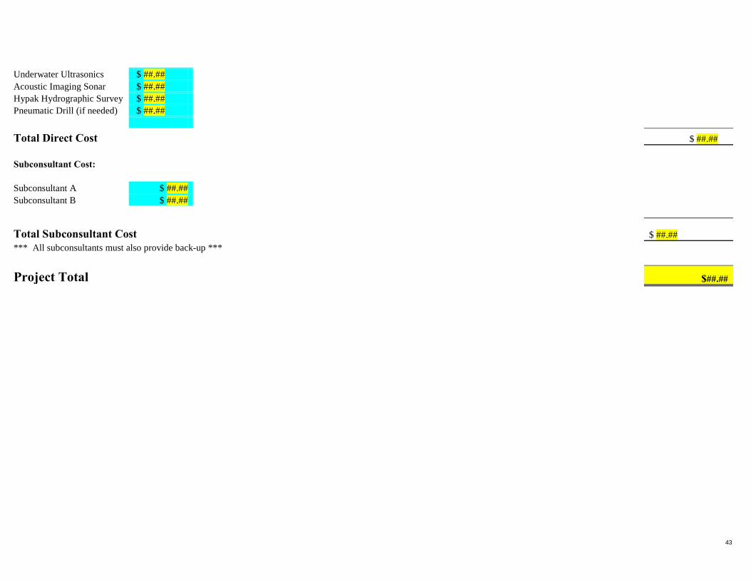
43
Underwater Ultrasonics $ ##.## Acoustic Imaging Sonar $ ##.## Hypak Hydrographic Survey $ ##.## Pneumatic Drill (if needed) $ ##.##
Total Direct Cost
$ ##.##
Subconsultant Cost:
Subconsultant A $ ##.## Subconsultant B $ ##.##
Total Subconsultant Cost
$ ##.##
*** All subconsultants must also provide back-up ***
Project Total
$##.##

APPENDIX H
Mississippi State Legal Load Truck Illustrations
