table of contents e83 body electrical
TRANSCRIPT
Initial Print Date: 10/03
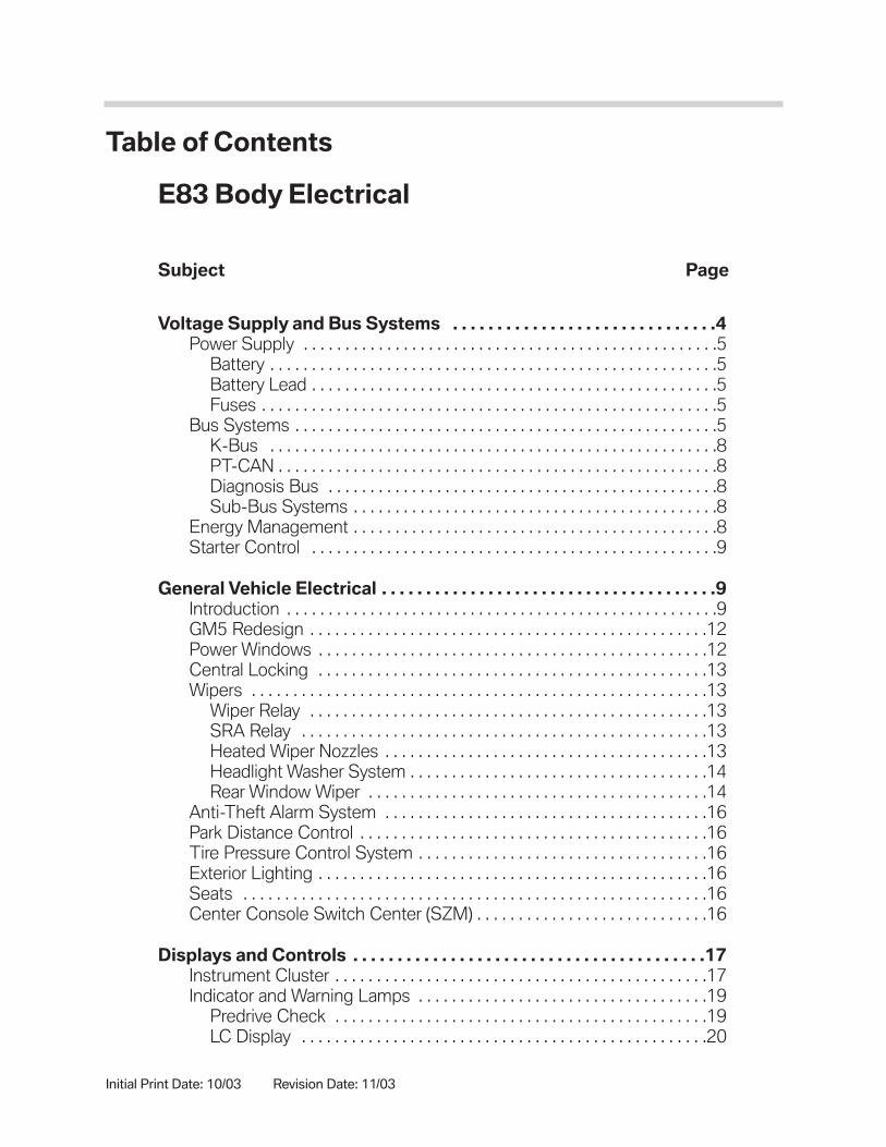
Table of Contents
Subject Page
Voltage Supply and Bus Systems . . . . . . . . . . . . . . . . . . . . . . . . . . . . . .4Power Supply . . . . . . . . . . . . . . . . . . . . . . . . . . . . . . . . . . . . . . . . . . . . . . . . . .5
Battery . . . . . . . . . . . . . . . . . . . . . . . . . . . . . . . . . . . . . . . . . . . . . . . . . . . . . .5Battery Lead . . . . . . . . . . . . . . . . . . . . . . . . . . . . . . . . . . . . . . . . . . . . . . . . .5Fuses . . . . . . . . . . . . . . . . . . . . . . . . . . . . . . . . . . . . . . . . . . . . . . . . . . . . . . .5
Bus Systems . . . . . . . . . . . . . . . . . . . . . . . . . . . . . . . . . . . . . . . . . . . . . . . . . . .5K-Bus . . . . . . . . . . . . . . . . . . . . . . . . . . . . . . . . . . . . . . . . . . . . . . . . . . . . . .8PT-CAN . . . . . . . . . . . . . . . . . . . . . . . . . . . . . . . . . . . . . . . . . . . . . . . . . . . . .8Diagnosis Bus . . . . . . . . . . . . . . . . . . . . . . . . . . . . . . . . . . . . . . . . . . . . . . .8Sub-Bus Systems . . . . . . . . . . . . . . . . . . . . . . . . . . . . . . . . . . . . . . . . . . . .8
Energy Management . . . . . . . . . . . . . . . . . . . . . . . . . . . . . . . . . . . . . . . . . . . .8Starter Control . . . . . . . . . . . . . . . . . . . . . . . . . . . . . . . . . . . . . . . . . . . . . . . . .9
General Vehicle Electrical . . . . . . . . . . . . . . . . . . . . . . . . . . . . . . . . . . . . . .9Introduction . . . . . . . . . . . . . . . . . . . . . . . . . . . . . . . . . . . . . . . . . . . . . . . . . . . .9GM5 Redesign . . . . . . . . . . . . . . . . . . . . . . . . . . . . . . . . . . . . . . . . . . . . . . . .12Power Windows . . . . . . . . . . . . . . . . . . . . . . . . . . . . . . . . . . . . . . . . . . . . . . .12Central Locking . . . . . . . . . . . . . . . . . . . . . . . . . . . . . . . . . . . . . . . . . . . . . . .13Wipers . . . . . . . . . . . . . . . . . . . . . . . . . . . . . . . . . . . . . . . . . . . . . . . . . . . . . . .13
Wiper Relay . . . . . . . . . . . . . . . . . . . . . . . . . . . . . . . . . . . . . . . . . . . . . . . .13SRA Relay . . . . . . . . . . . . . . . . . . . . . . . . . . . . . . . . . . . . . . . . . . . . . . . . .13Heated Wiper Nozzles . . . . . . . . . . . . . . . . . . . . . . . . . . . . . . . . . . . . . . .13Headlight Washer System . . . . . . . . . . . . . . . . . . . . . . . . . . . . . . . . . . . .14Rear Window Wiper . . . . . . . . . . . . . . . . . . . . . . . . . . . . . . . . . . . . . . . . .14
Anti-Theft Alarm System . . . . . . . . . . . . . . . . . . . . . . . . . . . . . . . . . . . . . . .16Park Distance Control . . . . . . . . . . . . . . . . . . . . . . . . . . . . . . . . . . . . . . . . . .16Tire Pressure Control System . . . . . . . . . . . . . . . . . . . . . . . . . . . . . . . . . . .16Exterior Lighting . . . . . . . . . . . . . . . . . . . . . . . . . . . . . . . . . . . . . . . . . . . . . . .16Seats . . . . . . . . . . . . . . . . . . . . . . . . . . . . . . . . . . . . . . . . . . . . . . . . . . . . . . . .16Center Console Switch Center (SZM) . . . . . . . . . . . . . . . . . . . . . . . . . . . .16
Displays and Controls . . . . . . . . . . . . . . . . . . . . . . . . . . . . . . . . . . . . . . . .17Instrument Cluster . . . . . . . . . . . . . . . . . . . . . . . . . . . . . . . . . . . . . . . . . . . . .17Indicator and Warning Lamps . . . . . . . . . . . . . . . . . . . . . . . . . . . . . . . . . . .19
Predrive Check . . . . . . . . . . . . . . . . . . . . . . . . . . . . . . . . . . . . . . . . . . . . .19LC Display . . . . . . . . . . . . . . . . . . . . . . . . . . . . . . . . . . . . . . . . . . . . . . . . .20
E83 Body Electrical
Revision Date: 11/03

Subject Page
Displays and Controls (cont.)Program and Gear Display . . . . . . . . . . . . . . . . . . . . . . . . . . . . . . . . . . .20Control Buttons . . . . . . . . . . . . . . . . . . . . . . . . . . . . . . . . . . . . . . . . . . . . .21On-Board Computer . . . . . . . . . . . . . . . . . . . . . . . . . . . . . . . . . . . . . . . .21Test Functions . . . . . . . . . . . . . . . . . . . . . . . . . . . . . . . . . . . . . . . . . . . . . .21Locking and Unlocking Test Functions . . . . . . . . . . . . . . . . . . . . . . . .21
Diagnosis . . . . . . . . . . . . . . . . . . . . . . . . . . . . . . . . . . . . . . . . . . . . . . . . . . . . .22CID . . . . . . . . . . . . . . . . . . . . . . . . . . . . . . . . . . . . . . . . . . . . . . . . . . . . . . . . . .22SIA IV Service Interval Indicator . . . . . . . . . . . . . . . . . . . . . . . . . . . . . . . . .23
Resetting Service Interval Indicator . . . . . . . . . . . . . . . . . . . . . . . . . . . .23
Information and Communication . . . . . . . . . . . . . . . . . . . . . . . . . . . . . .24Radio and CD Changer . . . . . . . . . . . . . . . . . . . . . . . . . . . . . . . . . . . . . . . .24CD Changer . . . . . . . . . . . . . . . . . . . . . . . . . . . . . . . . . . . . . . . . . . . . . . . . . .25
CDC Location . . . . . . . . . . . . . . . . . . . . . . . . . . . . . . . . . . . . . . . . . . . . . .25Aerial System . . . . . . . . . . . . . . . . . . . . . . . . . . . . . . . . . . . . . . . . . . . . . . . . .25
AM and FM Aerials . . . . . . . . . . . . . . . . . . . . . . . . . . . . . . . . . . . . . . . . .25Aerial Amplifier . . . . . . . . . . . . . . . . . . . . . . . . . . . . . . . . . . . . . . . . . . . . .26FM Aerial Diversity . . . . . . . . . . . . . . . . . . . . . . . . . . . . . . . . . . . . . . . . . .26
Service Mode . . . . . . . . . . . . . . . . . . . . . . . . . . . . . . . . . . . . . . . . . . . . . . . . .27BMW Business CD . . . . . . . . . . . . . . . . . . . . . . . . . . . . . . . . . . . . . . . . .27CID Radio . . . . . . . . . . . . . . . . . . . . . . . . . . . . . . . . . . . . . . . . . . . . . . . . . .27Car and Key Memory . . . . . . . . . . . . . . . . . . . . . . . . . . . . . . . . . . . . . . . .27
Audio Systems . . . . . . . . . . . . . . . . . . . . . . . . . . . . . . . . . . . . . . . . . . . . . .28New Features . . . . . . . . . . . . . . . . . . . . . . . . . . . . . . . . . . . . . . . . . . . . . . . . .28HiFi System . . . . . . . . . . . . . . . . . . . . . . . . . . . . . . . . . . . . . . . . . . . . . . . . . .28
HiFi Amplifier . . . . . . . . . . . . . . . . . . . . . . . . . . . . . . . . . . . . . . . . . . . . . . .30Top HiFi System . . . . . . . . . . . . . . . . . . . . . . . . . . . . . . . . . . . . . . . . . . . . . .30Top HiFi Audio System . . . . . . . . . . . . . . . . . . . . . . . . . . . . . . . . . . . . . . . . .32
SPDIF . . . . . . . . . . . . . . . . . . . . . . . . . . . . . . . . . . . . . . . . . . . . . . . . . . . . .32
Telephone System . . . . . . . . . . . . . . . . . . . . . . . . . . . . . . . . . . . . . . . . . . .33Telematic Control Unit TCU . . . . . . . . . . . . . . . . . . . . . . . . . . . . . . . . . . . . .33Principle of Operation . . . . . . . . . . . . . . . . . . . . . . . . . . . . . . . . . . . . . . . . . .33Compensator . . . . . . . . . . . . . . . . . . . . . . . . . . . . . . . . . . . . . . . . . . . . . . . . .36GPS Aerial . . . . . . . . . . . . . . . . . . . . . . . . . . . . . . . . . . . . . . . . . . . . . . . . . . . .36Telephone Aerial . . . . . . . . . . . . . . . . . . . . . . . . . . . . . . . . . . . . . . . . . . . . . .36
Navigation . . . . . . . . . . . . . . . . . . . . . . . . . . . . . . . . . . . . . . . . . . . . . . . . . . .37

3E83 Body Electrical
Body Electrical
Model: E83
Production: Start of Production MY 2004
After completion of this module you will be able to:
• Identify locations of major electrical components
• Know the differences in the audio systems
• Relate Bus Systems Layout

Voltage Supply and Bus Systems
The E83 electrical system is on the E46 electrical system and E85 system components.The systems have been adapted to the vehicle and their functions improved and extended.
The bus systems K-bus, PT-CAN, LIN bus and the diagnosis bus are used. The instru-ment cluster is the central gateway module. The luggage compartment houses the vehicle battery and the luggage compartment fuse holder. The luggage compartmentfuse holder supplies the glovebox fuse holder.
4E83 Body Electrical
G
+
-
KOMBIEWS
M
R
1 20
TE03-3311
30
R 15
50
15
30
21
1110
4
5
67
12
8
9
1. Starter 7. Luggage compartment fuse holder2. Alternator 8. Valvetronic or common rail3. Not used for U.S. 9. Top HiFi amplifier4. Glovebox fuse holder 10. Electronic immobilizer5. Safety battery terminal 11. Instrument cluster6. Vehicle battery 12. Ignition/starter switch
Voltage Supply Schematic

Power Supply
BatteryDifferent vehicle batteries with different capacities are used depending on the engine andequipment specification. The battery is located in the luggage compartment in thespare-wheel recess.
Battery LeadThe E83 has different battery leads depending on the engine variant. The B+batterycable is routed through the interior of the X3, along the floor on the passenger side. TheB+ cable is made of aluminum and has a diameter of 80mm2.
FusesThe E83 is equipped with two fuse holders. The luggage compartment fuse holder withthe fuse of the front fuse holder is located next to the vehicle battery in the spare wheelrecess.
The glovebox fuse holder carries the majority of the fuses. The main fuses for the DMEand the ignition/starter switch are located on the rear side of the glovebox fuse holder.
Bus Systems
The Bus system of the E83 is based on the E46 with minor upgrades.
The following Bus Systems are used on the E83:
• K-Bus
• PT-CAN
• Diagnosis Bus
• Sub-Bus Systems (BSD, LIN, M, Data Interface)
5E83 Body Electrical
E83 fuse Panel behind Glove BoxE83 Luggage Compartment Fuse Boxw/ Top HiFi Fuse.

K-BusThe K-bus links the components of the general vehicle electrical system, the informationand communications systems and the safety system. The majority of the systems andcomponents has been taken from other models and adapted to the E83.
A new feature is the control system for the new panorama sunroof (MDS) and the safetysystem (MRS4RD).
The satellite radio (SDARS) has been adapted to the connection to the K-bus.
The data transfer rate is 9.6 kbit.
PT-CANThe PT-CAN links the components of the control units for the drive and chassis systems.
Newly incorporated is the VG-SG control unit for the transfer case.
The data transfer rate is 500 kbit.
Diagnosis BusThe diagnosis bus is connected with two leads to the overall bus system. The PIN 7diagnostic connector lead is directed to the DME and transfers all the emissions-relateddata from the engine management system and from the automatic gearbox.
The PIN 8 diagnostic connector is connected to the remaining control units either directlyor via the instrument cluster as gateway.
The data transfer rate is 9.6 kbit. The rate of transfer of emissions related dataKWP2000* (E-OBD and OBD) is 10.4 kbit.
Sub-Bus SystemsThe following sub-buses are used in the E83:
• BSD Bit-serial data interface - connection of electronic engine management andalternator
• LIN Local Interconnected Network - connection of AHL and bi-xenon headlights,connection of GM5 and driver's or door mirror switch block
• M-bus - connection of IHKA/IHKR and stepping motors
Energy Management
Energy management for the E83 is taken from the E46. The software for regulating thecharging voltage is in the DME. In the event of an increased current consumption in thevehicle electrical system, the charging voltage specification can be increased. The charg-ing voltage specification is issued by the DME via the bit-serial data interface to the alter-nator.
6E83 Body Electrical

7E83 Body Electrical
TE03-3306
K-Bus
PT-CAN
LIN-Bus
Kombi
GM
5R
DE
WS
III
+
RL
S
MD
SS
ZM
SM
PD
C
LS
ZR
AD
IO
CID
MR
S 4
RD
OC
3
CD
C
NA
V
HIF
IS
DA
RS
TE
L
SE
S
DS
C
VG
-S
G
LW
S
EG
SIH
KA
DS
C-S
EN
AH
L
XE
NO
N
XE
NO
N
DM
E/D
DE
8 7
SV
T
MF
L
E83 Bus Chart

TE03-3826
K-Bus
PT-CAN
LIN-Bus
Kombi
GM
5R
DE
WS
III
+
RL
S
MD
SS
ZM
SM
PD
C
LS
ZR
AD
IO
CID
MR
S 4
RD
OC
3
CD
C
NA
V
HIF
I
TE
L
SE
S
DS
C
VG
-S
G
LW
S
EG
S
SD
AR
S
IHK
A
DS
C-S
EN
AH
L
XE
NO
N
XE
NO
N
DM
E/D
DE
8 7
SV
T
MF
L
E8
5E
83
E6
0E
53
E4
6
8E83 Body Electrical
E83 System Origin Chart

The charging voltage can be regulated as a function of the outside temperature. Thus thebattery can be charged to optimum effect. At low temperatures, the charging voltage canbe increased to obtain a higher capacity. At high temperatures, the charging voltage isreduced to avoid excessive gassing. The maximum charging voltage is 14.8 V.
A battery change does not have to be communicated to the DME control unit.
Energy management also features the option of load/consumer shutdown. In the event ofexcessive current consumption in the vehicle, the power output of the heated rear win-dow can be reduced.
Starter Control
EWS III plus is used in the E83. The basic function of starter control and enabling of DMEand EGS has remained the same. With EWS III plus the terminal 50 information is for-warded not from the starter motor but rather directly from the EWS control unit to theinstrument cluster. A circuit is hardwired from the output of the starter relay in the EWS IIIplus control unit directly to the instrument cluster. In order to avoid erroneous measure-ments, no sensor values are stored during the starting process.
General Vehicle Electrical
Introduction
The general vehicle electrical system of the E83 is for the most part based on the centralbody electronics 5 ZKE 5 of the E46.
The functions of the general vehicle electrical system are comparable to those of thegeneral vehicle electrical system on the E46:
• Central locking
• Power windows, different to the E46
• Wipe/wash system
• Anti-theft alarm system
• Interior Lights
• Consumer shutdown
• Remote control operation
• Door mirror control
• Car and Key Memory
9E83 Body Electrical

10E83 Body Electrical
System Overview

11E83 Body Electrical
1 Door mirror, left-hand side 33 Footwell lights
2 Central locking, driver's side 34 Ambient lights
3 Lock cylinder, driver's door 35 Power-window motor passenger side front with antitrap
4 Power window, driver's side with anti-trap protection 36 Central locking, passenger side, front
5 Center-lock button 37 Power-window switch, passenger side, front
6 Central locking system remote control 38 Center console switch center
7 Interior tailgate opening button 39 Integrated automatic heating and air conditioning
8 Tilt sensor 40 Rear-view mirror with rain/light sensor
9 Siren 41 Seat adjustment
10 Ultrasonic interior movement detector 42 Ignition/starter switch
11 Wiper switch 43 Digital motor electronics
12 Power-window switch, driver's side, rear 44 Electronic immobilizer
13 Power-window motor, driver's side rear with anti-trap 45 Light switch cluster
14 Central locking, driver's side,rear 46 Exterior lighting WIWA Wipe/wash system
15 Bonnet contact switch 47 Lights operating unit FH Power windows
16 Exterior tailgate opening button 48 Panorama glass sunroof drivemotor
17 Power distributor, front 49 Panorama glass sunroof control unit
18 Vanity mirror light 50 Panorama glass sunroof switch IB Interior Lights
19 Vanity-mirror light 51 Instrument cluster VA Consumer shutdown
20 Central locking, boot lid 52 Panorama glass sunroof drive motor
21 Fuel filler flap central locking 53 Outside temperature sensor
22 Central locking, passenger side,rear 54 EGS
23 Power-window motor,passenger side rear with antitrap 55 Engine management
24 Power-window switch, passenger side, rear 58 Door mirror, right
25 Headlight cleaning system relay K-BUS Body bus
26 Headlight cleaning system pump LIN-Bus Local Interconnected Network bus
27 Washer fluid pump PT-CAN Powertrain CAN
28 Relay, wipe/wash system ZV Central locking
29 Wipe/wash system DWA Anti-theft alarm system
30 Glovebox light FZV Central locking system remote control
31 Luggage-compartment light CKM Car and Key Memory
32 Interior/reading lights, front

The GM5RD communicates with the following components on the LIN bus:
• Door mirror, driver
• Door mirror, passenger side
• Switch block, driver
The stored positions of the door mirrors are lost if the GM5RD is replaced.
GM5 Redesign
The General Module 5 Redesign (GM5RD) is the heart of the general vehicle electricalsystem. The GM5RD, which was used on the E85, has been further developed for theE83 with a combined K-/LIN bus module. The K-/LIN bus module is integrated in theGM5RD for operation of the door mirrors.
Power Windows
The power windows of the E83 are controlled by the GM5RD similar to the operation inthe E46. The anti-trapping feature has been modified and the anti-trap strip is not usedin the E83. Anti-trapping is provided by the EKS electronics included in the individualwindow motors.
The SBFA (drivers door switch block assembly) is connected to the GM5RD via the LINBus. The passenger door switch and both rear door switch assemblies are connecteddirectly via hardwire to the GM5RD.
12E83 Body Electrical
1. SBFA2. GM5RD3. Driver’s power window motor4. Driver’s door contact5. Driver’s side rear door contact6. Driver’s side rear window switch7. Driver’s side rear power window
motor8. Passenger rear door power window
motor9. Passenger rear window switch
10. Passenger door rear contact switch11. Passenger door front contact switch12. Passenger front power window
motor13. Passenger front window switch

Central Locking
The functions of the Central Locking system is the same as those on the E46. TheGM5RD is the master control unit for the central locking system, and all requests areprocessed through the GM5RD.
Wipers
The wiper system has been modified for use in the E83. The GM5RD controls frontwiper and washer operation as well as headlight washer operation. The rear wiper andrear washer are controlled by a wiper module with operation requested directly by thewiper switch.
Wiper RelayThe dual relay is located in the E-Box.
SRA RelayThe SRA (headlight washing system) relay is located in the glove box fuse carrier.
Heated Wiper NozzlesThe heating element of the front washer nozzles are switched by an inline ambient tem-perature sensor via terminal 15. The current draw of the heating elements is controlledby a PTC resistor as a function of temperature.
13E83 Body Electrical
1. Central Locking, drivers doorw/Hall sensors
2. GM5RD3. Tailgate Release Button4. Central Locking, driver’s side
rear door w/Hall sensor5. Centerlock Button6. Remote control antenna7. Tailgate Lock Assembly8. Passenger door rear, w/Hall
sensor9. Fuel Filler Flap Locking
10. Passenger door front,, w/Hall sensor
11. Luggage Compartment Light
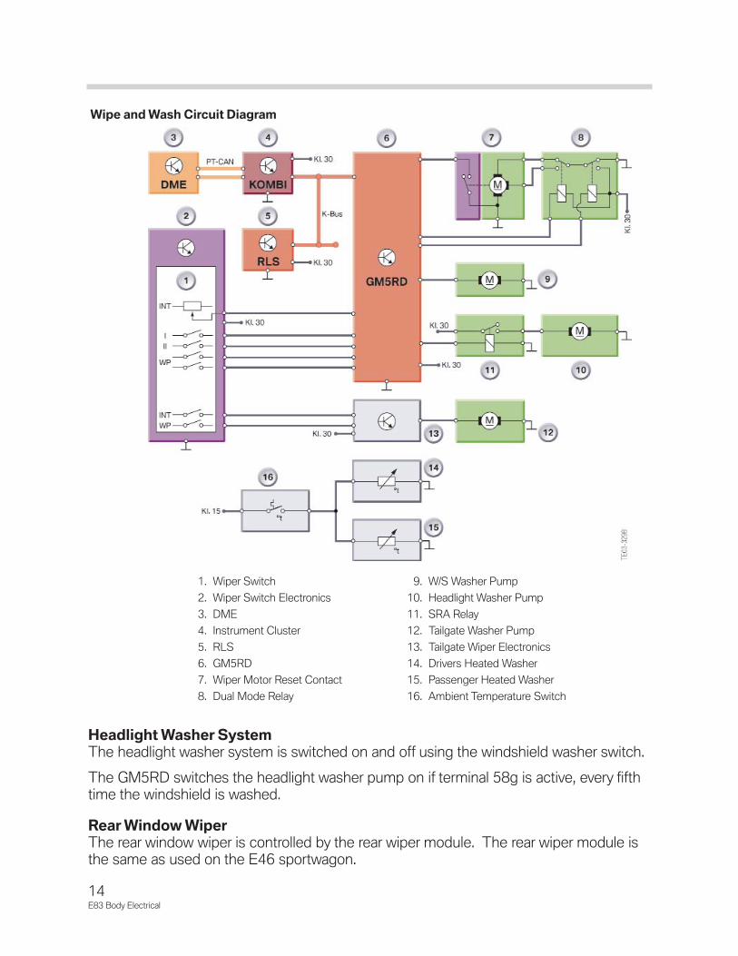
Headlight Washer SystemThe headlight washer system is switched on and off using the windshield washer switch.
The GM5RD switches the headlight washer pump on if terminal 58g is active, every fifthtime the windshield is washed.
Rear Window WiperThe rear window wiper is controlled by the rear wiper module. The rear wiper module isthe same as used on the E46 sportwagon.
14E83 Body Electrical
Wipe and Wash Circuit Diagram
1. Wiper Switch2. Wiper Switch Electronics3. DME4. Instrument Cluster5. RLS6. GM5RD7. Wiper Motor Reset Contact8. Dual Mode Relay
9. W/S Washer Pump10. Headlight Washer Pump11. SRA Relay12. Tailgate Washer Pump13. Tailgate Wiper Electronics14. Drivers Heated Washer15. Passenger Heated Washer16. Ambient Temperature Switch

Door Mirrors
There are two door mirror versions fitted to the E83. The low version(standard) door mir-rors have the following functions:
• Electric mirror adjustment
• Mirror heating
The high version (optional) door mirrors have the following functions:
• Electric mirror adjustment
• Mirror heating
• Mirror folding
All mirror functions for both exterior mirrors are controlled by the GM5RD. The GM5RDmakes all decisions concerning mirror movement and passes instructions to the mirrorelectronics (contained in the mirrors) via the LIN bus.
Potentiometers in the mirror electronics monitor position. Current position is sent to theGM5RD on a cyclical basis, and last mirror position is stored in the GM5RD.
The mirror switch in the SBFA communicates with the GM5RD via the LIN bus.
15E83 Body Electrical
1. GM5RD2. Mirror electrics, right3. Mirror heating, right4. Mirror vertical motor,
right5. Mirror horizontal motor,
right6. Mirror fold motor, right7. Mirror Pot, right8. Mirror Pot, right9. Mirror Fold motor, left
10. Mirror horizontal motor, left
11. Mirror vertical motor, left12. Mirror heating, left13. Mirror electrics, left14. SBFA

Anti-Theft Alarm System
The DWA anti-theft alarm system is the same as used on the E46. The DWA has beenmodified for use on the E83. The alarm is not standard, but a dealer installed option.
Park Distance Control
The PDC Park Distance Control has been taken from the E53. The PDC has been modified for use on the E83.
Tire Pressure Control System
The E83 is equipped with the RPA tire defect (RDW) indicator as standard.
Exterior Lighting
The exterior lighting function has been taken from the E46. The control unit is the lightswitch cluster. The lamps have been modified to the design of the E83. RLS is standardon all E83’s. Bi-xenon lights with AHL are optional.
Seats
The seat functions have been taken from the E46. The design has been modified for theE83. The following seat variants are fitted on the E83:
• Mechanical adjustment seats standard on some models
• Electric seat with memory
• Electric sports seat with memory
The memory function can only be used for the driver's seat. Seat heating with lumbarsupport is also optional.
Center Console Switch Center (SZM)
The SZM is used from the E53. Opening of the tailgate from the SZM is not possible.There are two variants:
• SZM Low with DSC, HDC and PDC
• SZM High with DSC, HDC, PDC and SHZ
The High variant may used as a replacement for the Low version.
16E83 Body Electrical

17E83 Body Electrical
Displays and Controls
Displays and Controls includes the following individual sections:
• Instrument cluster
• Central Information Display
• Service Interval Indicator
Instrument Cluster
The instrument cluster in the E83 is similar to that of the E85. The following changeshave been made to the E83 cluster:
• The end scale value (maximum speed reading) has been reduced to 250 km/h
• There are no indicator lamps for the EPS or DTC
• A wiper fluid indicator lamp has been added.

18E83 Body Electrical
Instrument Cluster Circuit Diagram
1. Brake lining wear sensor, LF2. DME3. DSC4. Outside Temperature Sensor5. Coolant Level Switch6. Not used in the USA7. Instrument Cluster
8. On-Board Computer button in turn signal stalk9. Reverse Light Switch, Manual Trans only
10. Fuse Box11. Parking brake switch12. Fuel level sensor 113. Fuel level sensor 214. Brake lining wear sensor, RR

Indicator and Warning Lamps
The indicator and warning lamps are activated by the processor in the instrument cluster.Important indicator and warning lamps are activated in the Predrive Check with terminal15 ''ON''. The indicator lamps and warning symbols are illuminated by permanentlywired-in LEDs (replacement of LEDs not possible).
Predrive CheckThe Predrive Check is a test of important indicator and warning lamps. In the PredriveCheck, these indicator and warning lamps are activated for 2 seconds with terminal 15''ON''. All the indicator and warning lamps are deactivated at the end of the PredriveCheck.
The following indicator and warning lamps are activated in the Predrive Check:
• Fuel reserve
• Coolant overtemperature
• Fasten seat belt (country-specific)
• Brake-lining wear
• General brake warning light (1 second yellow, 1 second red)
• RDW (1 second yellow, 1 second red)19
E83 Body Electrical
1. Speedometer2. Indicator Warning Lamps3. Tachometer4. Coolant Temperature Guage5. Fuel Guage
6. Button for display of Time and Service Interval7. Display for Selector lever and program display8. Button for reset of Trip Odometer and Time9. Display for Time, Service Interval, OBC

• Oil pressure/oil level (1 second yellow, 1 second red)
• Gearbox limp-home program
• Washer fluid
• Lamp fault (Check Control)
• Battery charge
LC DisplayThe LC display is integrated in the speedometer. The LC display indicates the kilometerreading/mileage and time as well as the on-board computer functions. The service inter-val indicator is also shown in the LC display.
A tampering dot indicates if there are different vehicle identification numbers in the lightswitch cluster and in the instrument cluster.
The LC display is made up of orange-colored segment characters(similar to a dot matrix).The brightness of the display is determined by the light switch cluster.
The LC display is activated with terminal R ''ON''.
Program and Gear DisplayOn vehicles fitted with an automatic gearbox, the program and gear display is featured ina separate LC display. The LC display is located between the speedometer and the revcounter. The program and gear display is activated with terminal 15 ''ON''.
The LC display for the program and gear display is made up of orange colored segments(dot matrix). The brightness of the display is determined by the light switch cluster .
The information between the control units for the automatic gearbox and the instrumentcluster is exchanged on the PT-CAN bus. A separate indicator lamp (see warning andindicator lamps) indicates the gearbox limp-home program in the event of a fault in theelectronic transmission control.
20E83 Body Electrical

The program and gear display shows lettersand numbers. The program mode is displayedon the left and the drive position on the right.
Control ButtonsTwo control buttons are located between the2 large needle instruments. The left button(S/R for Set/Reset) is used to reset the trip-odometer reading, to call up the test functionsand to call up the reset menu for the serviceinterval indicator.
The right button (clock symbol) is used to setthe time and to switch the service interval indi-cator (remaining distance/service date or viceversa).
On-Board ComputerThe on-board computer functions are indicated in the bottom line of the LC display. Thesoftware used in the instrument cluster of the E83 is the same as that used in the E85.All the functions are identical and are described in the vehicle documentation for the E85.
The displays of the on-board computer can be displayed and scrolled through in theinstrument cluster using the button in the turn indicator and High beam switch.
Test FunctionsThe test functions are used by service mechanics to check the coding. The test functionsare also tools for fault finding without a diagnostic tester. The test functions are onlyshown in the LC display of the instrument cluster. The test functions are activated bypressing the left control button in the instrument cluster (S/R, 5 seconds) with terminal Ror terminal 15 ''ON''.
In addition, the test functions can still be called up by pressing the left control button S/Rfor Set/Reset) in the instrument cluster with simultaneous activation of terminal R.
Locking and Unlocking Test FunctionsOnly the first two test functions are freely accessible. All test functions after the third testfunction are locked. Unlocking can only be carried out removed by means of test function19. In test function 19, the display switches in intervals of 1 second from L_on to L_off(Lock on and Lock off). The test functions are unlocked or locked by pressing the leftcontrol button (S/R for Set/Reset).
21E83 Body Electrical
1. Set/Reset 2. Clock Symbol
1. Program Mode 2. Drive Position

If the left control button (S/R for Set/Reset) in the instrument cluster is pressed whileL_off is displayed, the test functions remain unlocked or are unlocked. The display jumpsto test function 0.
If the left control button (S/R for Set/Reset) in the instrument cluster is pressed whileL_on is displayed, the test functions remain locked or are locked. The test functions canbe locked by means of test function 19.
Diagnosis
There are three possible combinations for replacing the instrument cluster/light switchcluster:
• Instrument cluster faulty, light switch cluster OK
• Light switch cluster faulty, instrument cluster OK
• Light switch cluster and instrument cluster must be replaced
Simultaneous replacement of the light switch cluster and the instrument cluster must beavoided. The odometer reading will be lost. In principle it is also possible to carry out atrial replacement of the instrument cluster/light switch cluster.
CID
The Central Information Display on the E83 is located in the center of the instrumentpanel immediately above the ventilation grille. The Central Information Display is identicalin design to the CID fitted in the E85.
The software used in the Central Information Display in the E83 is the same as that usedin the E85. All the functions are identical and are described in the vehicle documentationfor the E85.
22E83 Body Electrical

SIA IV Service Interval Indicator
The BMW maintenance system SIA IV (service interval indicator) is used in the E83. Theservice interval indicator is a system subject to constant development which in its devel-opment stages has been integrated in various model series such as the E85 and E46.
The service interval indicator appears in the LC display in the instrument cluster'sspeedometer. The indicator is shown for five seconds in the LC display after terminalR ''ON''.
Resetting Service Interval IndicatorResetting the service interval indicator for the oil service and inspection can only be per-formed by pressing the left button in the instrument cluster.
23E83 Body Electrical

Information and Communication
The BMW X3 is a premium vehicle in the SAV (Sports Activity Vehicle) range. The X3information and communication systems also offer current technology which meets thehighest standards. For example, DVD navigation with color screen, Bluetooth telephonetechnology (not at SOP) and audio systems with digital sound improvement are alloffered in the X3.
Radio and CD Changer
The radios in the E83 are identical to those in the E85 except for the color of the front fin-isher panel. The controls and functional efficiency also correspond to those of the E85radio systems.
The E83 does come with a BMW Business Radio w/CD as Standard.
Additionally available is the BMW Central Information Display CID radio w/ navigation.
All radios are new generation radios (NG radios). The radios feature a K-bus connectionvia which they communicate with other control units. Radios with a cassette deck are nolonger available.
A 6-CD changer is also available for the E83. The CD changer audio signals have a levelof 2.0 V (increased interference voltage distance). New generation radios detect whetherthey are communicating with a 0.5 V CD changer (old) or a 2.0 V CD changer (new) andswitch over the input accordingly.
24E83 Body Electrical
BMW CD Business w/CD
BMW CID Radio w/ Navigation
Model HiFi Audio System Top HiFi Audio System CDC
Business Radio w/CD Standard Optional Optional
CID Radio w/Nav Standard Optional Optional

CD Changer
The CD changer is a standard 6 disc CDchanger as fitted on the E46. The CD changeris suitable for the new generation radios (2.0 Vaudio output).
CDC LocationFor the first time in a BMW model, the CDchanger is located in a user friendly positionbetween the driver's seat and front passenger'sseat in the front armrest (forced connection withoption 473). The snap-in adapter for the mobilephone is housed in a flap above the CDchanger.
Aerial System
The E83 has up to 6 aerial systems depending on the options installed, not including theaerial for the remote control services (FBD).
The E83 features the following aerial systems:
• FM 1 - 3 window aerials in the rear window
• FM aerial 4 in the rear spoiler
• AM aerial in the rear spoiler
• Telephone aerial (roof-mounted aerial)
• GPS aerial for the navigation system (roof-mounted aerial)
• SDARS aerial for the digital radio in the USA (roof-mounted aerial)
AM and FM AerialsThe aerial structures for the FM aerials 1 - 3 are integrated in the rear window. The rearwindow is made of toughened safety glass (ESG) and is approximately 3.1 mm thick.
The AM aerial is in the rear spoiler. To avoid disturbances in AM reception through thethird brake light in the rear spoiler, there is a suppressor filter in the feed line to the thirdbrake light.
The power supply to the AM and FM aerial amplifier comes from the radio via terminalRad_on.
25E83 Body Electrical

Aerial AmplifierThe aerial amplifier for AM, FM and (FBD) as well as the aerial diversity module are builtinto a housing. The module is fitted on the inside of the tailgate.
FM Aerial DiversityThe tuner is connected to the aerial diversity module via an aerial connector (Fakra) and acoaxial cable. The antenna diversity switches to the next aerial as soon as the signalquality of the active FM aerial exceeds a defined threshold value. No interruption can beheard when the diversity module switches over. Evaluation of the signal quality and theswitch over only occur in the aerial diversity module.
26E83 Body Electrical
Aerial Systems Installation Locations
1. AM Aerial2. FM Aerial 43. Amplifier with Diversity Module4. Roof-mounted Shark Fin, with aerial
for Telephone, Nav and SDARS5. Not used in USA6. Heated rear window with FM 1-37. Not used in USA
1. Heated rear window heating wires with built in FM Aerials
2. Input: Term 30, Radio On,FBD Output
3. Input/Output: Coaxial Cable4. Input: FM 4 Aerial, FBD input, AM 5. Input: FM Aerial 1-36. Aerial Amplifier with Diversity

Service Mode
BMW Business CDThe following procedure applies to BMW CD radio and Business CD:
• Switch on the radio
• Press the "m" button within 8 seconds and hold for at least 8 seconds
• The functions listed in the following table are now possible via the service menu
• Switch off the radio to exit service mode
CID RadioThe following procedure applies to BMW CID Radio:
• Switch on the radio
• Press the "SEL" button within 8 seconds and hold for at least 8 seconds
• Switch off the radio to exit service mode
Car and Key MemoryThe following functions are stored in car and key memory:
• Sound settings
• Audio source
• The last station accessed is stored
27E83 Body Electrical

Audio Systems
The various audio systems of the E83 are described in this technical documentation.The radio systems originate from the E85. The loudspeaker systems are new develop-ments and are adapted to the acoustic and technical dimension requirements of the E83.
The following audio systems are available for the E83:
• HiFi audio system (Standard)
• Top HiFi audio system
The BMW audio standards which have been applied since the E85 are also being appliedto the E83. They apply to the HiFi and Top HiFi systems with regard to symmetry of thesound field, sound pressure and linearity of the frequency response.
New Features
New features by comparison with the E85:
• Central woofers for the HiFi and Top HiFi audio systems are fitted. The central bassprinciple applies to the systems in the E65/E60.
• The HiFi amplifier in the E83 luggage compartment is a modified version of the HiFiamplifier from the E85/E46. A 6 channel amplifier is adapted from the 10 channel hifiamplifier via internal switch changes.
• A fuse is added to the Carver Top HiFi amplifier from the E85 but is otherwiseinstalled in the E83 without further modifications.
HiFi System
28E83 Body Electrical
1. Business Radio2. Front Tweeters3. Front Broadband
Speakers4. Central Woofers5. Rear Broadband
Speakers6. HiFi Amplifier

29E83 Body Electrical
1. Instrument Cluster 5. Front Broadband Speakers
2. Business CD Radio 6. Central Woofers
3. Aerials for AM/FM and diversity module 7. Rear Broadband Speakers
4. Front Tweeters 8. HiFi Amplifier, 6 channel
HiFi Schematic

The HiFi audio system features a 6 channel analogue amplifier that is connected directlyto the 4 speaker outputs of the radio. The loudspeakers are connected to the 6 HiFiamplifier out channels. The tweeters are protected from overload by capacitors in thesupply lead and connected in parallel to the broadband speakers.
All sound controlling functions such as volume, bass, treble, fader, and GAL are per-formed in the radio.
HiFi AmplifierThe 6 channel HiFi amplifier in the luggagecompartment of the E83 is a modified versionof the 10 channel HiFi amplifier from theE85/E46. Four channels are for the door loud-speakers (broad-band loudspeaker or broad-band speaker with additional tweeter) and 2channels are for the central woofers.
The housing is constructed in the same way asthe 10 channel HiFi amplifier in the E85/E46.The HiFi amplifier has on output of 4 x 25 wattsfor the mid-range and high-ranges and 2 x 40watts for the low frequency.
Top HiFi System
30E83 Body Electrical
1. Business Radio2. Front Tweeters3. Front Broadband
Speakers4. Central Woofers5. Rear Tweeters6. Rear Broadband
Speakers7. Carver Top HiFi
Amplifier

31E83 Body Electrical
1. Instrument Cluster 6. Central Woofers2. BMW Business CD Radio 7. Rear Tweeters3. Aerials AM/FM and diversity module 8. Rear Broadband Speakers4. Front Tweeters 9. Carver Top HiFi Amplifier5. Front Broadband speakers
Top HiFi Schematic

Top HiFi Audio System
The Top HiFi audio system features a 10 channel amplifier with digital signal processortechnology for sound control. The Top HiFi amplifier is controlled via the two radio ana-logue audio signals.
The Top HiFi amplifier features a digital input for the CD changer. The digital input is onlyused for the BMW Business CD radio and CD changer combination. The 10 loudspeak-ers are directly connected to the 10 output channels of the Top HiFi amplifier. The activefrequency gates for adaptation of the loudspeakers are built into the amplifier.
Depending on the radio, various functions can be called up. Sound control functions suchas volume, bass, treble, fader, GAL, spatial sound simulation etc. are formed in the TopHiFi amplifier. The 7 band graphic equalizer can only be used in connection with the CIDradio.
Top HiFi Amplifier
A fuse is added to the familiar Carver Top HiFiamplifier from the E85 but is otherwise installedin the E83 without further modifications.
However, special Carver woofers with increasedcone excursion are used in the E83 that are usedin the the E85. The space available in the E83and the resonance volume in the side sill enablesthe use of the central bass principle.
The central woofers in the Top HiFi audio systemare simply adapted to the increased voltage levelof the bass end levels (8 . impedance). Theamplifier delivers 6 x 20 watts,2 x 40 watts and 2 x 100 watts.
SPDIFThe digital connection between the Top HiFiamplifier and the CD changer is an SPDIF connec-tion. SPDIF stands for Sony Philips Digital Interfaceand is a data transfer standard for digital audio data.The data can be transferred optically via fibre-opticcables or via coaxial cables depending on the unit.
Advantage: the digital data is read by the CD andtransferred between the units with the highest pos-sible quality, as no digital/analogue conversion isnecessary. The Top HiFi amplifier also no longerhas to carry out analogue/digital conversion. Thedigital data can therefore be processed directlyfrom the DSP (Digital Sound Processor).
32E83 Body Electrical
1. 46-pin connector2. Digital input for CDC3. Fuse
1. Top HiFi Amplifier (HiFi Amplifier also)2. Navigation3. Not used in USA4. SDARS

Telephone System
The Everest platform for the telephone and telematics functions are used in the US ver-sion of the E83. For the American market, three different versions are offered:
• TCU only with telematics function emergency call (E-Call) and breakdown call (B-Call). (Optional w/Premium Package
• TCU with telematic function emergency call and enabling by provider.
• TCU with telematics and telephone functions via hands-free unit or mobile phone(after retrofitting a telephone).
Telematic Control Unit TCU
The Telematic Control Unit TCU is optional equipment in US vehicles. This means thatan emergency call can always be made(if the car is equipped with the TCU), also if thecustomer has not (yet) retrofitted a telephone.
The range of functions of the US version is as follows:
• TCU is always fitted in order to ensure the emergency call can be made even if notelephone is present
• Dual-band 800 MHz and 1900 MHz
• Combined transmit/receive module NAD (Network Access Device) for analog AMPS(American Mobile Phone Standard) for telephone calls and digital CDMA (CodeDivision Multiplex Algorithm) for telematics functions
• Eject box with charging unit for Motorola Phoenix V60
• Telematics functions (E/B call)
• GPS receiver for localization
Principle of Operation
In the US version, the Telematic Control Unit has an NAD (Network Access Device) thatworks in the AMPS/CDMA standard with the frequencies 800/1900 MHz. The TCU fea-tures a hands-free system with full-duplex transmission. This makes it possible to speakand listen simultaneously. The position of the vehicle is determined by the TCU by meansof a built-in GPS receiver. In the event of a crash, the TCU sends an SMS with this loca-tion data to the provider. Furthermore, the TCU has an interface for the connection of anemergency call button (E/B Call). The emergency call button is a dual function switchwith two keys: one for the emergency call and one for the breakdown call. The emer-gency call button is standard equipment.
33E83 Body Electrical

34E83 Body Electrical
1. MFL w/ Telephone Button 7. GPS Aerial
2. CID 8. Hands-free Microphone
3. Speaker 9. Emergency Call and Assistance Buttons
4. Motorola Mobile Phone 10. CID control panel (Radio)
5. Compensator 11. TCU
6. Phone Aerial
Telephone Overview

35E83 Body Electrical
Telephone Circuit Diagram
1. Hands-free Microphone 5. Eject Box w/Mobile Phone 9. GPS Aerial2. BMW Business CD Radio 6. Phone Aerial 10. Call Buttons3. MFL w/Telephone Button 7. Compensator4. Speaker 8. TCU
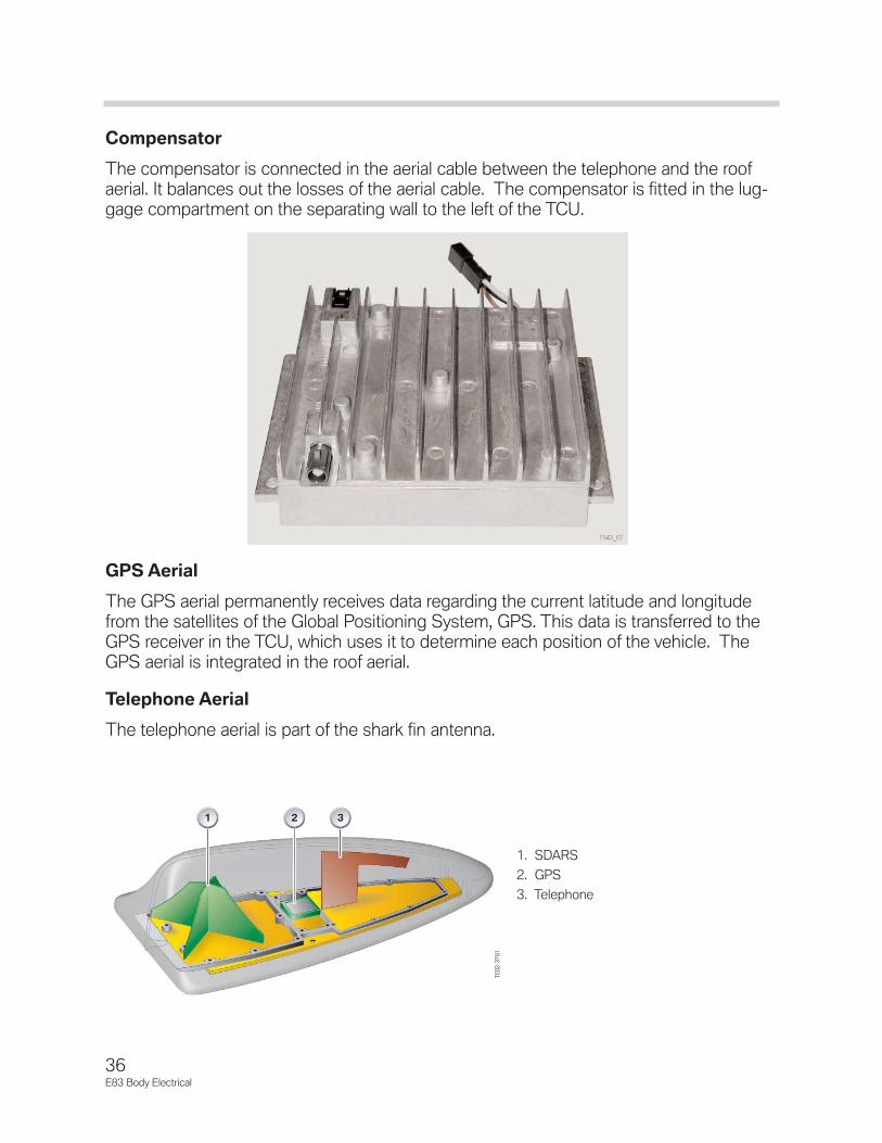
Compensator
The compensator is connected in the aerial cable between the telephone and the roofaerial. It balances out the losses of the aerial cable. The compensator is fitted in the lug-gage compartment on the separating wall to the left of the TCU.
GPS Aerial
The GPS aerial permanently receives data regarding the current latitude and longitudefrom the satellites of the Global Positioning System, GPS. This data is transferred to theGPS receiver in the TCU, which uses it to determine each position of the vehicle. TheGPS aerial is integrated in the roof aerial.
Telephone Aerial
The telephone aerial is part of the shark fin antenna.
36E83 Body Electrical
1. SDARS2. GPS3. Telephone

Navigation
One navigation system is available optionally in the E83. The Professional Navigation withCID and Business Radio with CD( MK-3 Nav with widescreen monitor), is the only systemavailable.
37E83 Body Electrical
1. Instrument Cluster2. CID3. CID Control Panel (Radio)4. DVD Navigation Computer5. GPS Aerial6. AM/FM Aerials with amplifier
and diversity

38E83 Body Electrical
Workshop Exercise - E83 Component Location

39E83 Body Electrical
Lo
cati
on
Acr
ony
mC
om
po
nen
tNam
eIt
em
1 2 3 4 5 6 7 8 9 10 11 12 13 14 15 16 17 18 19 20 21

40E83 Body Electrical

41E83 Body Electrical
Lo
cati
on
Acr
ony
mC
om
po
nen
tNam
eIt
em
1 2 3 4 5

42E83 Body Electrical

43E83 Body Electrical
Lo
cati
on
Acr
ony
mC
om
po
nen
tNam
eIt
em
1 2 3 4 5 6 7 8

44E83 Body Electrical

45E83 Body Electrical
Lo
cati
on
Acr
ony
mC
om
po
nen
tNam
eIt
em
1 2 3 4 5 6 7 8 9 10 11 12 13 14 15 16

46E83 Body Electrical
AHL Active Headlight ControlUnitAntenna Amplifier andDiversity
AUC Auto Recirc Air ControlSensor
Battery
Bluetooth Antenna
CDC Compact Disc Changer
CID Central Information Display
DME Digital Motor Electronics
Door Pressure SensorRight
Door Pressure Sensor Left
DSC Dynamic Stability Control
DVD Navigation Computer
DXC Dynamic X Drive Control
EGS Electronic TransmissionControl
Eject Box
EWS Electronic VehicleImmobilization
GM5RD General Module
GPS GPS Antenna, alsoTelephone and SDARS
HiFi HiFi Amplifier, also Top HiFiAmplifier
KOMBI Instrument Cluster
LSZ Light Switch Cluster
Light Switch Panel
Main Fuse and PowerDistribution Box
MDS Multi Drive SunroofControl Unit
MRS Multiple Restraint System
NG Tilt Sensor
Oil Level Sensor
PDC Park Distance Control
Radio
RLS Rain Light Sensor
SBSL Satellite Crash SensorB-Pillar Left
SBSR Satellite Crash SensorB-Pillar Right
SDARS Satellite Radio Receiver
SES Voice Recognition
SINE Emergency Power Sensor
Solar Sensor
SVT Servotronic Control Unit
TCU Telematics Control Unit
Up Front Sensor
Up Front Sensor
USIS Ultrasonic Car Alarm

E83 Workshop Exercise A/CCustomer has just picked up their new X3. Almost immediately they return with a com-plaint of no fan in the car.
1. Perform Short Test.
2. List the pertinent faults for this complaint.
3. From what source does the affected control module receive its B+?
4. Are those fuses good?
5. Explain the operation of K19 and how it affects the power supply.
6. Check for power at the affected control module.
What is the voltage on the pin(s) that supply B+?
7. What is the next most likely source of the problem?
8. Where is K19?
9. Could you substitute K6304 for K19?
10. List the other components similar to K19 and their location.
11. What is the results of Test Function 7.2 of the Instrument Cluster?
47E83 Body Electrical