table of contents division page - missouri department of
TRANSCRIPT
TABLE OF CONTENTS DIVISION PAGE DIVISION 1 – GENERAL REQUIREMENTS (BROAD SCOPE) 3 01019 CONTRACT REQUIREMENTS 3 01039 COORDINATION AND MEETING REQUIREMENT 5 01300 SUBMITTAL REQUIREMENTS 8 01400 QUALITY CONTROL REQUIREMENTS 12 01500 CONSTRUCTION FACILITIES AND TEMPORARY CONTROL REQUIREMENTS 14 01600 MATERIAL AND EQUIPMENT REQUIREMENT 16 01650 STARTING OF SYSTEMS REQUIREMENT 18 01700 CONTRACT CLOSEOUT REQUIREMENT 20 DIVISION 2 - SITEWORK 22 02220 EXCAVATING, BACKFILLING AND COMPACTING 23 02221 TRENCHING, BACKFILLING AND COMPACTING 29 02280 TERMITE CONTROL 34 02660 WATER DISTRIBUTION SYSTEM 36 02685 GAS DISTRIBUTION SYSTEM 44 02730 SANITARY SEWERAGE SYSTEM 51 DIVISION 3 - CONCRETE 56 03100 CONCRETE FORMWORK 56 03200 CONCRETE REINFORCEMENT 60 03300 CAST-IN-PLACE CONCRETE 62 03346 CONCRETE FLOOR FINISHING 67 03370 CONCRETE CURING 69 DIVISION 5 - METALS 71 05500 METAL FABRICATIONS 71 DIVISION 6 - WOOD AND PLASTIC 73 06112 FRAMING AND SHEATHING 73 DIVISION 7 - THERMAL AND MOISTURE PROTECTION 75 07210 BUILDING INSULATION 75 07212 BOARD INSULATION 77 07411 METAL ROOF AND WALL PANELS 79 07465 ALUMINUM SOFFIT PANELS 84 07631 GUTTERS AND DOWNSPOUTS 87 07900 JOINT SEALERS 89 DIVISION 8 - DOORS AND WINDOWS 92 08111 STANDARD STEEL DOORS 92 08112 STANDARD STEEL FRAMES 95 08360 SECTIONAL OVERHEAD DOORS 98 08520 ALUMINUM WINDOWS 102 08710 DOOR HARDWARE 104 08720 ELECTRIC DOOR OPERATORS 107 08800 GLAZING 109 DIVISION 9 - FINISHES 111 09260 GYPSUM BOARD SYSTEM 111 09511 SUSPENDED ACOUSTIC CEILINGS 113 09900 PAINTING 116 DIVISION 10 - SPECIALTIES 120 10800 TOILET AND BATH ACCESSORIES 120 DIVISION 15 - MECHANICAL 122 15050 MATERIALS AND METHODS 122 15400 PLUMBING SYSTEMS 124 15410 COMPRESSED AIR PIPING 126 15440 PLUMBING FIXTURES 129 15441 PRE-CAST TRENCH DRAINAGE SYSTEM 131 15490 NATURAL GAS PIPING 133

15500 HEATING, VENTILATING AND AIR CONDITIONING 134 15887 CARBON MONOXIDE EXHAUST SYSTEMS 139 15990 TESTING AND BALANCING 142 DIVISION 16 - ELECTRICAL 147 16100 ELECTRICAL WORK 147 16101 GENERAL 147 16102 FIELD CONDITIONS AND MEASUREMENTS 147 16103 CLEANUP 147 16104 GUARANTEE 147 16105 CODES 147 16106 SUBMITTALS 147 16107 QUALITY ASSURANCE 148 16108 CONDUIT 148 16109 WIRE AND CABLE 148 16110 JUNCTION AND OUTLET BOXES 149 16111 LIGHTING FIXTURES 149 16112 WIRING DEVICES 149 16113 PANELBOARDS 150 16114 TRANSFORMERS 150 16115 DISCONNECT SWITCHES 150 16116 GROUNDING 150 16117 OTHER MATERIALS 150 16118 EXECUTION 150 16119 PREPARATION 150 16120 TRENCHING AND BACKFILLING 151 16121 INSTALLATION OF RACEWAYS AND FITTINGS 151 16122 INSTALLATION OF CONDUCTORS 151 16123 INSTALLATION OF PANELS 151 16124 TESTING AND INSPECTION 151 16125 PROJECT COMPLETION 152
Page 3
01019
CONTRACT REQUIREMENTS PART 1 GENERAL 1.1 SECTION INCLUDES A. Schedule of values. B. Application for payment. C. Change procedures. D. Alternatives. 1.2 RELATED SECTIONS A. Section 01600 - Material and Equipment: Product substitutions. 1.3 SCHEDULE OF VALUES
A. Submit a printed schedule on Contractor's standard form. Electronic media printout will be considered.
B. Submit Schedule of Values in duplicate within 20 days after date of Owner-Contractor Agreement. C. Revise schedule to list approved Change Orders, with each Application For Payment. 1.4 APPLICATIONS FOR PAYMENT A. Submit four copies of each application on Contractor's electronic media driven form. B. Content and Format: Utilize Schedule of Values for listing items in Application for Payment. C. Payment Period: 30 days. D. Include an updated construction progress schedule. E. Certified payroll records. 1.5 CHANGE PROCEDURES A. The Architect/Engineer/Designer may issue a Notice of Change that includes a detailed description
of a proposed change with supplementary or revised Drawings and specifications, a change in Contract Time for executing the change with a stipulation of any overtime work required.
B. The Contractor may propose changes by submitting a request for change to the
Architect/Engineer/Designer describing the proposed change and its full effect on the Work. Include a statement describing the reason for the change, the effect on the Contract Sum/Price and Contract Time, and a statement describing the effect on Work by the MoDOT District or other Contractors.
C. Stipulated Sum/Price Change Order: Based on Notice of Change and Contractor's fixed price
quotation or Contractor's request for a Change Order as approved by Architect/Engineer/Designer. D. Construction Change Directive: Architect/Engineer/Designer may issue a directive instructing the
Contractor to proceed with a change in the Work, for subsequent inclusion in a Change Order. Document will describe changes in the Work, and designate method of determining any change in Contract Sum/Price or Contract Time. Promptly execute the change.
Page 4
E. Time and Material Change Order: Submit itemized account and supporting data after completion
of change, within time limits indicated in the Conditions of the Contract. Architect/Engineer/Designer will determine the change allowable in Contract Sum/Price and Contract Time as provided in the Contract Documents.
F. Maintain detailed records of work done on Time and Material basis. Provide full information
required for evaluation of proposed changes, and to substantiate costs for changes in the Work. G. Execution of Change Orders: Architect/Engineer/Designer will issue Change Orders for signatures
of parties as provided in the Conditions of the Contract. 1.6 DEFECT ASSESSMENT A. Replace the Work, or portions of the Work, not conforming to specify requirements.
B. If, in the opinion of the Architect/Engineer/Designer, it is not practical to remove and replace the Work, the Architect/Engineer/Designer will direct an appropriate remedy or adjust payment.
1.7 ALTERNATIVES A. Accepted Alternatives will be identified in Owner-Contractor Agreement.
END OF SECTION
Page 5
01039
COORDINATION AND MEETING REQUIREMENT PART 1 GENERAL 1.1 SECTION INCLUDES A. Coordination and project conditions. B. Field engineering. C. Preconstruction meeting. D. Site mobilization meeting. E. Progress meetings. F. Preinstallation meetings. G. Equipment electrical characteristics and components. H. Examination. I. Preparation. J. Cutting and Patching. K. Alteration project procedures. 1.2 COORDINATION AND PROJECT CONDITIONS A. Coordinate scheduling, submittals, and Work of the various sections of the Project Manual to
ensure efficient and orderly sequence of installation of interdependent construction elements. B. Verify utility requirements and characteristics of operating equipment are compatible with building
utilities. Coordinate work of various sections having interdependent responsibilities for installing, connecting to and placing in service, such equipment.
C. Coordinate space requirements, supports, and installation of mechanical and electrical Work, which
are indicated diagrammatically on Drawings. Follow routing shown for pipes, ducts, and conduit, as closely as practicable; place runs parallel with lines of building. Utilize spaces efficiently to maximize accessibility for other installations, for maintenance, and for repairs.
D. In finished areas, except as otherwise indicated, conceal pipes, ducts and wiring within the
construction. Coordinate locations of fixtures and outlets with finish elements. E. Coordinate completion and clean up of Work of separate sections in preparation for Substantial
Completion. F. After Owner occupancy of premises, coordinate access to site for correction of defective Work and
Work not in accordance with Contract Documents, to minimize disruption of Owner's activities. 1.3 FIELD ENGINEERING A. Employ a Land Surveyor registered in the State of Missouri and acceptable to
Architect/Engineer/Designer. B. Owner will locate and protect survey control and reference points. C. Control datum for survey is that established by Owner provided survey. D. Verify setbacks and easements; confirm drawing dimensions and elevations. E. Provide field engineering services. Establish elevations, lines and levels, utilizing recognized
engineering survey practices. 1.4 PRECONSTRUCTION MEETING A. Architect/Engineer/Designer will schedule a meeting after Notice of Award.

Page 6
B. Attendance Required: District engineer or representative, Architect/Engineer/Designer and Contractor.
C. Record minutes and distribute copies within 5 days after meeting to participants, with two copies to District Engineer, Architect/Engineer/Designer, participants and those affected by decisions made.
1.5 SITE MOBILIZATION MEETING
A. Architect/Engineer/Designer will schedule a meeting at the Project site prior to Contractor occupancy.
B. Architect/Engineer/Designer will record minutes and distributes copies within 5 days after meeting
to participants, with two copies to Architect/Engineer/Designer, participants and those affected by decisions made.
1.6 PROGRESS MEETINGS A. Schedule and administer meetings throughout progress of the Work at when arranged by
Architect/Engineer/Designer. B. Architect/Engineer/Designer will make arrangements for meetings, prepare agenda with copies for
participants, and preside at meetings. C. Attendance Required: Job superintendent, major Subcontractors and suppliers, District engineer
representative, Architect/Engineer/Designer, as appropriate to agenda topics for each meeting. D. Agenda: 1. Review of Work progress. 2. Field observations, problems, and decisions. 3. Identification of problems, which impede planned progress. 4. Maintenance of progress schedule. 5. Corrective measures to regain projected schedules. 6. Coordination of projected progress. 7. Effect of proposed changes on progress schedule and coordination. E. Record minutes and distributes copies within 5 days after meeting to participants and those affected
by decisions made. 1.7 PREINSTALLATION MEETING A. When required in individual specification sections, convene a pre-installation meeting at the site
prior to commencing work of the section. B. Notify Architect/Engineer/Designer seven days in advance of meeting date. C. Prepare agenda and preside at meeting: 1. Review conditions of installation, preparation and installation procedures. 2. Review coordination with related work. D. Record minutes and distributes copies within 5 days after meeting to participants and those affected
by decisions made. PART 2 PRODUCTS Not used

Page 7
PART 3 EXECUTION 3.1 CUTTING AND PATCHING A. Employ skilled and experienced installer to perform cutting and patching. B. Submit written request in advance of cutting or altering elements, which affect: 1. Structural integrity of element. 2. Integrity of weather-exposed or moisture-resistant elements. 3. Work of Owner or separate contractor. C. Execute cutting, fitting, and patching to complete Work, and to: 1. Uncover Work to install or correct ill-timed Work. 2. Remove and replace defective and non-conforming Work.
3. Provide openings in elements of Work for penetrations of mechanical and electrical Work. D. Cut masonry and concrete materials using masonry saw or core drill. E. Fit Work tight to pipes, sleeves, ducts, conduit and other penetrations through surfaces. F. Maintain integrity of wall, ceiling, or floor construction; completely seal voids. G. Refinish surfaces to match adjacent finishes. For continuous surfaces, refinish to nearest
intersection; for an assembly, refinish entire unit. H. Identify hazardous substances or conditions exposed during the Work to the
Architect/Engineer/Designer for decision or remedy. 3.2 ALTERATION PROJECT PROCEDURES A. Materials: As specified in Product sections; match existing Products and work for patching and
extending work. B. Close openings in exterior surfaces to protect existing work from weather and extremes of
temperature and humidity. C. When finished surfaces are cut so that a smooth transition with new Work is not possible, terminate
existing surface along a straight line at a natural line of division and submit recommendation to Architect/Engineer/Designer for review.
D. Patch or replace portions of existing surfaces that are damaged, lifted, discolored or showing other
imperfections. E. Finish surfaces as specified in individual Product sections.
END OF SECTION

Page 8
01300
SUBMITTAL REQUIREMENTS PART 1 GENERAL 1.1 SECTION INCLUDES A. Submittal procedures. B. Construction progress schedules. C. Proposed Products list. D. Product Data. E. Shop Drawings. F. Samples. G. Design data. H. Test reports. I. Certificates. J. Manufacturer's instructions. K. Manufacturer's field reports. L. Erection drawings. M. Construction photographs. 1.2 RELATED SECTIONS A. Section 01300 - Submittals B. Section 01400 - Quality Control: Manufacturers' field services and reports. C. Section 01700 - Contract Closeout: Contract warranties, bonds, manufacturers' certificates and
closeout submittals. 1.3 REFERENCES A. AGC Associated General Contractors of America publication "The Use of CPM in Construction - A
Manual for General Contractors and the Construction Industry". 1.4 SUBMITTAL PROCEDURES A. Submit five (5) hard copies of each submittal with Architect/Engineer/Designer accepted form. B. Identify Project, Contractor, Subcontractor or supplier; pertinent drawing and detail number and
specification section number, as appropriate. C. Apply Contractor's stamp, signed or initialed certifying that review, approval, verification of
Products required, field dimensions, adjacent construction Work and coordination of information is in accordance with the requirements of the Work and Contract Documents.
D. Schedule submittals to expedite the Project, and deliver to Architect/Engineer/Designer at business
address. Coordinate submission of related items. E. For each submittal for review, allow 15 days excluding delivery time to and from the contractor. F. Identify variations from Contract Documents and Product or system limitations, which may be
detrimental to successful performance of the completed Work. G. Submittals not requested will not be recognized or processed.
Page 9
1.5 CONSTRUCTION PROGRESS SCHEDULES A. Submit initial schedule in duplicate within 15 days after date established in Notice to Proceed. B. Revise and resubmit as required. C. Submit revised schedules with each Application for Payment, identifying changes since previous
version. D. Submit a horizontal bar chart with separate line for each major portion of Work or operation,
identifying first workday of each week. 1.6 PROPOSED PRODUCTS LIST A. Within 15 days after date of Notice to Proceed, submit list of major products proposed for use, with
name of manufacturer, trade name and model number of each product. B. For products specified only by reference standards, give manufacturer, trade name, model or
catalog designation and reference standards. 1.7 PRODUCT DATA A. Product Data for Review: 1. Submitted to Architect/Engineer/Designer for review for the limited purpose of checking
for conformance with information given and the design concept expressed in the contract documents.
2. After review, provide copies and distribute in accordance with SUBMITTAL PROCEDURES article above and for record documents purposes described in Section 01700 - CONTRACT CLOSEOUT.
B. Product Data for Information: 1. Submitted for the Architect/Engineer/Designer’s knowledge as contract administrator or for the
Owner. C. Product Data for Project Closeout: 1. Submitted for the Owner's benefit during and after project completion. D. Submit the number of copies, which the Contractor requires, plus two copies that will be retained
by the Architect/Engineer/Designer. E. Mark each copy to identify applicable products, models, options and other data. Supplement
manufacturers' standard data to provide information specific to this Project. F. After review distribute in accordance with the Submittal Procedures article above and provide
copies for record documents described in Section 01700 - CONTRACT CLOSEOUT. 1.8 SHOP DRAWINGS A. Shop Drawings for Review: 1. Submit five (5) hard copies to Architect/Engineer/Designer for review for the limited
purpose of checking for conformance with information given and the design concept expressed in the contract documents.
2. After review, produce copies and distribute in accordance with SUBMITTAL PROCEDURES article above and for record documents purposes described in Section 01700 - CONTRACT CLOSEOUT.
B. Shop Drawings for Information: 1. Submitted for the Architect/Engineer/Designer’s knowledge as contract administrator or
for the Owner.
Page 10
C. Shop Drawings For Project Closeout: 1. Submitted for the Owner's benefit during and after project completion. D. Indicate special utility and electrical characteristics, utility connection requirements and location of
utility outlets for service for functional equipment and appliances. E. Submit in the form of one reproducible transparency and one opaque reproduction. 1.9 SAMPLES A. Samples for Review: 1. Submitted to Architect/Engineer/Designer for review for the limited purpose of checking
for conformance with information given and the design concept expressed in the contract documents.
2. After review, produce duplicates and distribute in accordance with SUBMITTAL PROCEDURES article above and for record documents purposes described in Section 01700 - CONTRACT CLOSEOUT.
B. Samples for Information: 1. Submitted for the Architect/Engineer/Designer’s knowledge as contract administrator or
for the Owner. C. Samples for Selection: 1. Submitted to Architect/Engineer/Designer for aesthetic, color, or finish selection. 2. Submit samples of finishes for Architect/Engineer/Designer selection. 3. After review, produce duplicates and distribute in accordance with SUBMITTAL
PROCEDURES article above and for record documents purposes described in Section 01700 - CONTRACT CLOSEOUT.
1.10 DESIGN DATA A. Submit for the Architect/Engineer/Designer’s knowledge as contract administrator or for the
Owner. B. Submit for information for the limited purpose of assessing conformance with information given
and the design concept expressed in the contract documents. 1.11 TEST REPORTS A. Submit for the Architect/Engineer/Designer’s knowledge as contract administrator or for the
Owner. B. Submit test reports for information for the limited purpose of assessing conformance with
information given and the design concept expressed in the contract documents. 1.12 CERTIFICATES A. When specified in individual specification sections, submit certification by the manufacturer,
installation/application subcontractor, or the Contractor to Architect/Engineer/Designer, in quantities specified for Product Data.
B. Indicate material or Product conforms to or exceeds specified requirements. Submit supporting reference data, affidavits and certifications as appropriate.
C. Certificates may be recent or previous test results on material or Product but must be acceptable to Architect/Engineer/Designer.
1.13 MANUFACTURER'S INSTRUCTIONS A. When specified in individual specification sections, submit printed instructions for delivery,

Page 11
storage, assembly, installation, and start-up, adjusting and finishing, to Architect/Engineer/Designer for delivery to owner in quantities specified for Product Data.
B. Indicate special procedures, perimeter conditions requiring special attention and special environmental criteria required for application or installation.
C. Refer to Section 01400 - Quality Control, Manufacturers' Field Services article. 1.14 MANUFACTURER'S FIELD REPORTS A. Submit reports for the Architect/Engineer/Designer's benefit as contract administrator or for the
Owner. B. Submit for information for the limited purpose of assessing conformance with information given
and the design concept expressed in the contract documents. 1.15 ERECTION DRAWINGS
A. Submit drawings for the Architect/Engineer/Designer’s benefit as contract administrator or for the Owner.
B. Submit for information for the limited purpose of assessing conformance with information given and the design concept expressed in the contract documents.
C. Data indicating inappropriate or unacceptable Work may be subject to action by the Architect/Engineer/Designer or Owner.
END OF SECTION
Page 12
01400
QUALITY CONTROL REQUIREMENTS PART 1 GENERAL 1.1 SECTION INCLUDES A. Quality assurance - control of installation. B. Tolerances C. References and standards. D. Mock-up. E. Inspecting and testing laboratory services. F. Manufacturers' field services. 1.2 RELATED SECTIONS A. Section 01300 - Submittals: Submission of manufacturers' instructions and certificates. B. Section 01600 - Material and Equipment: Requirements for material and product quality. C. Section 01650 - Starting of Systems. 1.3 QUALITY ASSURANCE - CONTROL OF INSTALLATION A. Monitor quality control over suppliers, manufacturers, Products, services, site conditions and
workmanship, to produce Work of specified quality. B. Comply with manufacturers' instructions, including each step in sequence. C. Should manufacturers' instructions conflict with Contract Documents, request clarification from
Architect/Engineer/Designer before proceeding. D. Comply with specified standards as minimum quality for the Work except where more stringent
tolerances, codes or specified requirements indicate higher standards or more precise workmanship. E. Perform Work by persons qualified to produce required and specified quality. F. Verify that field measurements are as indicated on shop drawings or as instructed by the
manufacturer. G. Secure Products in place with positive anchorage devices designed and sized to withstand stresses,
vibration, physical distortion, or disfigurement. 1.4 TOLERANCES A. Monitor fabrication and installation tolerance control of Products to produce acceptable Work. Do
not permit tolerances to accumulate. B. Comply with manufacturers' tolerances. Should manufacturers' tolerances conflict with Contract
Documents, request clarification from Architect/Engineer/Designer before proceeding. C. Adjust Products to appropriate dimensions; position before securing Products in place. 1.5 REFERENCES AND STANDARDS A. For Products or workmanship specified by association, trade or other consensus standards, comply
with requirements of the standard, except when more rigid requirements are specified or are required by applicable codes.
Page 13
B. Conform to reference standard by date of issue current on date for receiving bids or date specified in the individual specification sections, except where a specific date is established by code.
C. Neither the contractual relationships, duties or responsibilities of the parties in Contract nor those of the Architect/Engineer/Designer shall be altered from the Contract Documents by mention or inference otherwise in any reference document.
1.6 TESTING SERVICES A. Contractor to provide all testing services as called out in these specifications. B. Testing and source quality control may occur on or off the project site. Perform off-site testing as
required by the Architect/Engineer/Designer or the Owner. C. Testing does not relieve Contractor to perform Work to contract requirements. D. Re-testing required because of non-conformance to specified requirements shall be performed by
the same MoDOT personnel on instructions by the Architect/Engineer/Designer. 1.7 INSPECTION SERVICES A. Owner will employ MoDOT Personnel to perform inspection. B. Inspecting may occur on or off the project site. Perform off-site inspecting as required by the
Architect/Engineer/Designer or the Owner. C. Inspecting does not relieve Contractor to perform Work to contract requirements. 1.8 MANUFACTURERS' FIELD SERVICES A. When specified in individual specification sections, require material or Product suppliers or
manufacturers to provide qualified staff personnel to observe site conditions, conditions of surfaces and installation, quality of workmanship, start-up of equipment, test, adjust and the balancing of equipment as applicable and to initiate instructions when necessary.
B. Report observations and site decisions or instructions given to applicators or installers that are supplemental or contrary to manufacturers' written instructions.
C. Refer to Section 01300 - SUBMITTALS, MANUFACTURERS' FIELD REPORTS article. PART 2 EXECUTION 2.1 EXAMINATION A. Verify that existing site conditions and substrate surfaces are acceptable for subsequent
Work. Beginning new Work means acceptance of existing conditions. B. Verify that existing substrate is capable of structural support or attachment of new Work
being applied or attached. 2.2 PREPARATION A. Clean substrate surfaces prior to applying next material or substance. B. Seal cracks or openings of substrate prior to applying next material or substance. C. Apply manufacturer required or recommended substrate primer, sealer or conditioner prior to
applying any new material or substance in contact or bond.
END OF SECTION

Page 14
01500
CONSTRUCTION FACILITIES AND TEMPORARY CONTROL REQUIREMENTS PART 1 GENERAL 1.1 SECTION INCLUDES A. Temporary Utilities: Electricity, telephone service, facsimile service and sanitary facilities. B. Temporary Controls: enclosures and fencing, protection of the Work and water control. C. Construction Facilities: progress cleaning and temporary buildings. 1.2 TEMPORARY ELECTRICITY A. Cost: By Contractor; pay for temporary power service furnished by MoDOT. 1.3 TELEPHONE SERVICE A. Provide, maintain, and pay for telephone service to field office and Architect/Engineer/Designer’s
field office at time of project mobilization. 1.4 TEMPORARY WATER SERVICE A. Connect to existing water source as directed for construction operations at time of project
mobilization. B. Contractor will reimburse Owner for water used in construction as agreed upon at time of project
mobilization. 1.5 TEMPORARY SANITARY FACILITIES A. Provide and maintain required facilities and enclosures. Provide at time of project mobilization. 1.6 FENCING A. Construction: Use plastic mesh safety fencing or better. B. Provide 48” high fence around construction site; equip with vehicular and pedestrian gates with
locks. 1.7 WATER CONTROL A. Grade site to drain. Maintain excavations free of water. Provide, operate and maintain pumping
equipment. B. Protect site from puddling or running water. Provide water barriers as required to protect site from
soil erosion. 1.8 EXTERIOR ENCLOSURES A. Provide temporary weather tight closure of exterior openings to accommodate acceptable working
conditions and protection for Products, to allow for temporary heating and maintenance of required ambient temperatures identified in individual specification sections, and to prevent entry of unauthorized persons. Provide access doors with self-closing hardware and locks.
Page 15
1.9 PROTECTION OF INSTALLED WORK A. Protect installed Work and provide special protection where specified in individual specification
sections. B. Provide temporary and removable protection for installed Products. Control activity in immediate
work area to prevent damage. C. Provide protective coverings at walls, projections, jambs, sills and soffits of openings. D. Protect finished floors, stairs, and other surfaces from traffic, dirt, wear, damage or movement of
heavy objects, by protecting with durable sheet materials. E. Prohibit traffic or storage upon waterproofed or roofed surfaces. If traffic or activity is necessary,
obtain recommendations for protection from waterproofing or roofing material manufacturer. F. Prohibit traffic from landscaped areas. 1.10 SECURITY A. Provide security and facilities to protect Work and existing facilities and Owner's operations from
unauthorized entry, vandalism or theft. B. Coordinate with Owner's security program. 1.11 ACCESS ROADS A. Provide and maintain access to fire hydrants, free of obstructions. B. Provide means of removing mud from vehicle wheels before entering streets. C. Designated existing on-site roads may be used for construction traffic. 1.12 PROGRESS CLEANING AND WASTE REMOVAL A. Maintain areas free of waste materials, debris and rubbish. Maintain site in a clean and orderly
condition. B. Remove debris and rubbish from pipe chases, plenums, attics, crawl spaces and other closed or
remote spaces, prior to enclosing the space. C. Broom and vacuum clean interior areas prior to start of surface finishing and continue cleaning to
eliminate dust. D. Collect and remove waste materials, debris and rubbish from site periodically and dispose off-site. E. Open free-fall chutes are not permitted. Terminate closed chutes into appropriate containers with
lids. 1.13 REMOVAL OF UTILITIES, FACILITIES, AND CONTROLS A. Remove temporary utilities, equipment, facilities and materials prior to Final Application for
Payment inspection. B. Clean and repair damage caused by installation or use of temporary work. C. Restore existing facilities used during construction to original condition. Restore permanent
facilities used during construction to specified condition. PART 2 PRODUCTS Not Used. PART 3 EXECUTION Not Used.
END OF SECTION
Page 16
01600
MATERIAL AND EQUIPMENT REQUIREMENT PART 1 GENERAL 1.1 SECTION INCLUDES A. Products. B. Transportation and handling. C. Storage and protection. D. Product options. E. Substitutions. 1.2 RELATED SECTIONS A. Instructions to Bidders: Product options and substitution procedures. B. Section 01400 - Quality Control: Product quality monitoring. 1.3 PRODUCTS A. Do not use materials and equipment removed from existing premises, except as specifically
permitted by the Contract Documents. B. Provide interchangeable components of the same manufacture for components being replaced. 1.4 TRANSPORTATION AND HANDLING A. Transport and handle Products in accordance with manufacturer's instructions. B. Promptly inspect shipments to ensure that Products comply with requirements, quantities are
correct and products are undamaged. C. Provide equipment and personnel to handle Products by methods to prevent soiling, disfigurement
or damage. 1.5 STORAGE AND PROTECTION A. Store and protect Products in accordance with manufacturers' instructions. B. Store with seals and labels intact and legible. C. Store sensitive Products in weather tight, climate controlled, enclosures in an environment
favorable to Product. D. For exterior storage of fabricated Products, place on sloped supports above ground. E. Provide bonded off-site storage and protection when site does not permit on-site storage or
protection. F. Cover Products subject to deterioration with impervious sheet covering. Provide ventilation to
prevent condensation and degradation of Products. G. Store loose granular materials on solid flat surfaces in a well-drained area. Prevent mixing with
foreign matter. H. Provide equipment and personnel to store Products by methods to prevent soiling, disfigurement or
damage.
Page 17
I. Arrange storage of Products to permit access for inspection. Periodically inspect to verify Products are undamaged and are maintained in acceptable condition.
1.6 PRODUCT OPTIONS A. Products Specified by Reference Standards or by Description Only: Any Product meeting those
standards or description is acceptable. B. Products Specified by Naming One or More Manufacturers: Products of manufacturers named and
meeting specifications, no options or substitutions allowed. C. Products Specified by Naming One or More Manufacturers with a Provision for Substitutions:
Submit a request for substitution for any manufacturer not named in accordance with the following article.
1.7 SUBSTITUTIONS A. Architect/Engineer/Designer will consider requests for Substitutions only within 15 days after date
established in Notice to Proceed. B. Substitutions may be considered when a Product becomes unavailable through no fault of the
Contractor. C. Document each request with complete data substantiating compliance of proposed Substitution with
Contract Documents. D. A request constitutes a representation that the Contractor:
1. Has investigated proposed Product and determined that it meets or exceeds the quality level of the specified Product.
2. Will provide the same warranty for the Substitution as for the specified Product. 3. Will coordinate installation and make changes to other Work that may be required for the
Work to be complete with no additional cost to Owner. 4. Waives claims for additional costs or time extension that may subsequently become
apparent. 5. Will reimburse Owner for review or redesign services associated with re-approval by
authorities. E. Substitutions will not be considered when they are indicated or implied on shop drawing or product
data submittals, without separate written request or when acceptance will require revision to the Contract Documents.
F. Substitution Submittal Procedure: 1. Submit three copies of request for Substitution for consideration. Limit each request to
one proposed Substitution. 2. Submit shop drawings, product data and certified test results attesting to the proposed
Product equivalence. Burden of proof is on proposer. 3. The Architect/Engineer/Designer will notify Contractor in writing of decision to accept or
reject request. PART 2 PRODUCTS Not Used. PART 3 EXECUTION Not Used.
END OF SECTION
Page 18
01650
STARTING OF SYSTEMS REQUIREMENT PART 1 GENERAL 1.1 SECTION INCLUDES A. Starting systems. B. Demonstration and instructions. C. Testing, adjusting and balancing. 1.2 RELATED SECTIONS A. Section 01400 - Quality Control: Manufacturers field reports. B. Section 01700 - Contract Closeout: System operation and maintenance data and extra materials. 1.3 STARTING SYSTEMS A. Coordinate schedule for start-up of various equipment and systems. B. Notify Architect/Engineer/Designer seven days prior to start-up of each item. C. Verify that each piece of equipment or system has been checked for proper lubrication, drive
rotation, belt tension, and control sequence and for conditions that may cause damage. D. Verify tests, meter readings, and specified electrical characteristics agree with those required by the
equipment or system manufacturer. E. Verify that wiring and support components for equipment are complete and tested. F. Execute start-up under supervision of applicable manufacturer's representative or Contractors'
personnel in accordance with manufacturers' instructions. G. When specified in individual specification Sections, require manufacturer to provide authorized
representative to be present at site to inspect, check and approve equipment or system installation prior to start-up and to supervise placing equipment or system in operation.
H. Submit a written report in accordance with Section 01300 that equipment or system has been
properly installed and is functioning correctly. 1.4 DEMONSTRATION AND INSTRUCTIONS A. Demonstrate operation and maintenance of Products to Owner's personnel two weeks prior to date
of Final Completion. B. For equipment or systems requiring seasonal operation, perform demonstration for other season
within six months. C. Utilize operation and maintenance manuals as basis for instruction. Review contents of manual with
Owners' personnel in detail to explain all aspects of operation and maintenance. D. Demonstrate start-up, operation, control, adjustment, trouble-shooting, servicing, maintenance and
shutdown of each item of equipment at agreed time, at equipment location.
Page 19
E. Prepare and insert additional data in operations and maintenance manuals when the need for additional data becomes apparent during instruction.
F. The amount of time required for instruction on each item of equipment and system that’s specified
in individual sections. PART 2 PRODUCTS Not Used. PART 3 EXECUTION Not Used.
END OF SECTION

Page 20
01700
CONTRACT CLOSEOUT REQUIREMENT PART 1 GENERAL 1.1 SECTION INCLUDES A. Closeout procedures. B. Final cleaning. C. Adjusting. D. Project record documents. E. Operation and maintenance data. F. Spare parts and maintenance Products. G. Warranties. 1.2 RELATED SECTIONS A. Section 01500 - Construction Facilities and Temporary Controls: Progress cleaning. B. Section 01650 - Starting of Systems: System start-up, testing, adjusting and balancing. 1.3 CLOSEOUT PROCEDURES A. Submit written certification that Contract Documents have been reviewed, Work has been
inspected, and that Work is complete in accordance with Contract Documents and ready for Architect/Engineer/Designer’s review.
B. Provide submittals to Owner that is required by governing or other authorities. C. Submit final Application for Payment identifying total adjusted Contract Sum, previous payments
and sum remaining due. D. Owner will occupy portions of the building as specified in Section 01010. E. Projects shall not be accepted by MoDOT until the vendor has completed all punch list items. The
vendor will then have 30 days to submit all required paperwork necessary to close the project. Failure to submit the required paperwork within 30 days could result in the debarment or suspension of the contractor from future projects
1.4 FINAL CLEANING A. Execute final cleaning prior to final project assessment. Clean interior and exterior glass, surfaces
exposed to view; remove temporary labels, stains and foreign substances, polish transparent and glossy surfaces, vacuum carpeted and soft surfaces.
B. Clean equipment and fixtures to a sanitary condition with cleaning materials appropriate to the
surface and material being cleaned. C. Clean or replace filters of operating equipment used during construction and/or adjustment. D. Clean debris from roofs, gutters, downspouts and drainage systems. E. Clean site; sweep paved areas, rake clean landscaped surfaces. F. Remove waste and surplus materials, rubbish and construction facilities from the site. 1.5 ADJUSTING A. Adjust operating Products and equipment to ensure smooth and unhindered operation.
Page 21
1.6 PROJECT RECORD DOCUMENTS A. Store record documents separate from documents used for construction. B. Record information concurrent with construction progress. C. Specifications: Legibly mark and record at each Product section description of actual Products
installed, including the following: 1. Manufacturer's name and product model and number. 2. Product substitutions or alternates utilized. 3. Changes made by Addenda and modifications. D. Record Drawings and Shop Drawings: Legibly mark each item to record actual construction
including: 1. Measured depths of foundations in relation to finish main floor datum. 2. Measured horizontal and vertical locations of underground utilities and appurtenances,
referenced to permanent surface improvements. 3. Measured locations of internal utilities and appurtenances concealed in construction,
referenced to visible and accessible features of the Work. 4. Field changes of dimension and detail. 5. Details not on original Contract drawings. E. Submit documents to Architect/Engineer/Designer’swith claim for final Application for Payment. 1.7 OPERATION AND MAINTENANCE DATA A. Submit data bound in 8-1/2 x 11 inch (A4) text pages, three D side ring binders with durable plastic
covers. B. Prepare binder cover with printed title "OPERATION AND MAINTENANCE INSTRUCTIONS",
title of project and subject matter of binder when multiple binders are required. C. Internally subdivide the binder contents with permanent page dividers, logically organized; with tab
titling clearly printed under reinforced laminated plastic tabs. D. Submit 1 draft copy of completed volumes 15 days prior to final inspection. This copy will be
reviewed and returned with Architect/Engineer/Designer comments. Revise content of all document sets as required prior to final submission.
E. Submit two sets of revised final volumes, within 10 days after final inspection. 1.8 SPARE PARTS AND MAINTENANCE PRODUCTS A. Provide spare parts, maintenance, and extra Products in quantities specified individual
specification sections. B. Deliver to Project site; obtain receipt prior to final payment. C. Examine system components at a frequency consistent with reliable operation. Clean, adjust and
lubricate as required. D. Include systematic examination, adjustment, and lubrication of components. Repair or replace parts
whenever required. Use parts produced by the manufacturer of the original component. E. Maintenance service shall not be assigned or transferred to any agent or Subcontractor without prior
written consent of the Owner. 1.9 WARRANTIES A. Execute and assemble transferable warranty documents from Subcontractors, suppliers and
manufacturers. B. Submit prior to final Application for Payment. C. For items of Work delayed beyond date of Final Completion, provide updated submittal within 10
days after acceptance, listing date of acceptance as start of the warranty period.
Page 22
PART 2 PRODUCTS Not Used. PART 3 EXECUTION Not Used.
END OF SECTION

Page 23
02220
EXCAVATING, BACKFILLING AND COMPACTING
PART 1 GENERAL 1.1 SUMMARY A Excavate, backfill, compact, and grade the site to the elevations shown on the Drawings, as
specified herein, and as needed to meet the requirements of the construction shown in the Contract Documents.
B. Related work: 1. Documents affecting work of this Section include, but are not necessarily limited to,
General Conditions, Supplementary Conditions and Sections in Division 1 of these Specifications.
1.2 QUALITY ASSURANCE A. Use adequate numbers of skilled workmen who are thoroughly trained and experienced in the
necessary crafts and who are completely familiar with the specified requirements and the methods needed for proper performance of the work of this Section.
B. Use equipment adequate in size, capacity and numbers to accomplish the work of this Section in a timely manner.
C. In addition to complying with requirements of governmental agencies having jurisdiction, comply with the directions of the MoDOT Inspector.
1.3 DELIVERY, STORAGE AND HANDLING A. Comply with pertinent provisions of Section 01620. PART 2 PRODUCTS 2.1 SOIL MATERIALS A. Fill and backfill materials: 1. Provide soil materials free from organic matter and deleterious substances, containing no
rocks or lumps over 6" in greatest dimension, and with not more than 15% of the rocks or lumps larger than 2-3/8" in their greatest dimension.
2. Fill material is subject to the approval of the MoDOT Inspector, and are those materials removed from excavations or imported from off-site borrow areas; predominantly granular, non-expansive soils free from roots and other deleterious matter.
3. Do not permit rocks having a dimension greater than 1" in the upper 12" of fill or embankment.
4. Cohesionless material used for structural backfill. Provide sand free from organic material and other foreign matter, and as approved by the MoDOT Inspector.
5. Where granular base is called for under building slabs, provide aggregate complying with requirements of Section 03300 of these Specifications.
2.2 WEED KILLER A. Provide a dry, free-flowing, dust-free chemical compound, soluble in water, capable of inhibiting
growth of vegetation, and approved for use on this Work by governmental agencies having jurisdiction.
Page 24
2.3 TOPSOIL A. Where and if shown on the Drawings or otherwise required, provide topsoil consisting of friable,
fertile soil of loamy character, containing an amount of organic matter normal to the region, capable of sustaining healthy plant life, and reasonably free from subsoil, roots, heavy or stiff clay, stones larger than 2" in greatest dimension, noxious weeds, sticks, brush, litter and other deleterious matter.
B. Obtain topsoil/backfill from sources within the project limits as approved by Owner, or provide
imported topsoil obtained from sources outside the project limits or from both sources. 2.4 OTHER MATERIALS A. Provide other materials, not specifically described but required for a complete and proper
installation, as selected by the Contractor subject to the approval of the Architect. PART 3 EXECUTION 3.1 SURFACE CONDITIONS A. Examine the areas and conditions under which work of this Section will be performed. Correct
conditions detrimental to timely and proper completion of the Work. Do not proceed until unsatisfactory conditions are corrected.
3.2 FINISH ELEVATIONS AND LINES A. Comply with pertinent provisions of Section 01050. 3.3 PROCEDURES A. Utilities: 1. Unless shown to be removed, protect active utility lines shown on the Drawings or
otherwise made known to the Contractor prior to excavating. If damaged, repair or replace at no additional cost to the Owner.
2. If active utility lines are encountered and are not shown on the Drawings or otherwise made known to the Contractor, promptly take necessary steps to assure that service is not interrupted.
3. If service is interrupted as a result of work under this Section, immediately restore service by repairing the damaged utility at no additional cost to the Owner.
4. If existing utilities are found to interfere with the permanent facilities being constructed under this Section, immediately notify the Architect and secure his instructions.
5. Do not proceed with permanent relocation of utilities until written instructions are received from the Architect.
B. Protection of persons and property: 1. Barricade open holes and depressions occurring as part of the Work, and post warning
lights on property adjacent to or with public access. 2. Operate warning lights during hours from dusk to dawn each day and as otherwise
required. 3. Protect structures, utilities, sidewalks, pavements and other facilities from damage caused
by settlement, lateral movement, washout and other hazards created by operations under this Section.
C. Dewatering: 1. Remove all water, including rainwater encountered during trench and sub-structure work
to an approved location by pumps, drains and other approved methods.

Page 25
2. Keep excavations and site construction area free from water. D. Use means necessary to prevent dust becoming a nuisance to the public, to neighbors and to other
work being performed on or near the site. E. Maintain access to adjacent areas at all times. 3.4 EXCAVATING A. Perform excavating of every type of material encountered within the limits of the Work to the lines,
grades and elevations indicated and specified herein. B. Satisfactory excavated materials: 1. Transport to and place in, fill or embankment areas within the limits of the Work. C. Unsatisfactory excavated materials: 1. Excavate to a distance below grade as directed by the MoDOT Inspector and replace with
satisfactory materials. 2. Include excavation of unsatisfactory materials and replacement by satisfactory materials,
as parts of the work of this Section. D. Surplus materials: 1. Dispose of unsatisfactory excavated material, and surplus satisfactory excavated material,
away from the site at disposal areas arranged and paid for by the Contractor. E. Excavation of rock: 1. Where rocks, boulders, granite, or similar material is encountered, and where such material
cannot be removed or excavated by conventional earth moving or ripping equipment, take required steps to proceed with the general grading operations of the Work, and remove or excavate such material by means which will neither cause additional cost to the Owner nor endanger buildings or structures whether on or off the site.
2. Do not use explosives without written permission from the Architect. F. Excavate and backfill in a manner and sequence that will provide proper drainage at all times. G. Borrow: 1. Obtain material required for fill or embankment in excess of that produced within the
grading limits of the Work from borrow areas selected and paid for by the Contractor and approved by the MoDOT Inspector.
H. Ditches and gutters: 1. Cut accurately to the cross sections, grades and elevations shown. 2. Maintain excavations free from detrimental quantities of leaves, sticks, trash, and other
debris until completion of the Work. 3. Dispose of excavated materials as shown on the Drawings or directed by the MoDOT
Inspector; except do not, in any case, deposit materials less than 3'-0" from the edge of a ditch.
I. Unauthorized excavation: 1. Unauthorized excavation consists of removal of materials beyond indicated subgrade
elevations or dimensions without specific instruction from the Architect or the MoDOT Inspector.
2. Under footings, foundations, or retaining walls: a. Fill unauthorized excavations by extending the indicated bottom elevation of the
footing or base to the excavation bottom, without altering the required top elevation.
Page 26
b. When acceptable to the soil engineer, lean concrete fill may be used to bring the
bottom elevation to proper position. 3. Elsewhere backfill and compact unauthorized excavations as specified for authorized
excavations, unless otherwise directed by the soil engineer. J. Stability of excavations: 1. Slope sides of excavations to 1:1 or flatter, unless otherwise directed by the MoDOT
Inspector. 2. Shore and brace where sloping is not possible because of space restrictions or stability of
the materials being excavated. 3. Maintain sides and slopes of excavations in a safe condition until completion of
backfilling. K. Excavating for structures:
1. Conform to elevations and dimensions shown within a tolerance of 0.10 ft, and extending a sufficient distance from footings and foundations to permit placing and removing concrete formwork, installation of services, other construction required and for inspection.
2. In excavating for footings and foundations, take care not to disturb bottom of excavation: a. Excavate by hand tools to final grade just before concrete is placed. b. Trim bottoms to required lines and grades to leave solid base to receive concrete. 3. Excavate for footings and foundations only after general site excavating, filling and
grading are complete. L. Excavating for pavements: 1. Cut surface under pavements to comply with cross sections, elevations and grades. M. Cold weather protection: 1. Protect excavation bottoms against freezing when atmospheric temperature is less than 35
degrees F. 3.5 FILLING AND BACKFILLING A. General: 1. For each classification listed below, place acceptable soil material in layers to required
subgrade elevations. 2. In excavations: a. Use satisfactory excavated or borrowed materials. 3. Under building slabs: a. Use subbase materials. 4. Under building slabs: a. Use granular fill, if so called for on the Drawings, complying with aggregate
acceptable under Section 03300 of these Specifications. B. Backfill excavations as promptly as progress of the Work permits, but not until completion of the
following. 1. Acceptance of construction below finish grade including, where applicable, dampproofing
and waterproofing. 2. Inspecting, testing, approving and recording locations of underground utilities. 3. Removing concrete formwork. 4. Removing shoring and bracing and backfilling of voids with satisfactory materials. 5. Removing trash and debris. 6. Placement of horizontal bracing on horizontally supported walls. C. Ground surface preparation: 1. Remove vegetation, debris, unsatisfactory soil materials, obstructions and deleterious
matter from ground surface prior to placement of fills.

Page 27
2. Plow, strip, or break up sloped surfaces steeper than one vertical to four horizontal so that fill material will bond with existing surface.
3. When existing ground surface has a density less than that specified under "compacting" for the particular area, break up the ground surface, pulverize, moisture-condition to the optimum moisture content and compact to required depth and percentage of maximum density.
D. Placing and compacting: 1. Place backfill and fill materials in layers not more than 8" in loose depth. 2. Before compacting, moisten or aerate each layer as necessary to provide the optimum
moisture content. 3. Compact each layer to required percentage of maximum density for area.
4. Do not place backfill or fill material on surfaces that are muddy, frozen or containing frost or ice.
5. Place backfill and fill materials evenly adjacent to structures, to required elevations. 6. Take care to prevent wedging action of backfill against structures by carrying the material
uniformly around the structure to approximately the same elevation in each lift. 7. Where the construction includes basement or other underground walls having structural
floors over them, do not backfill such walls until the structural floors are in place and have attained sufficient strength to support the walls.
3.6 GRADING A. General: 1. Uniformly grade the areas within limits of grading under this Section, including adjacent
transition areas. 2. Smooth the finished surfaces within specified tolerance. 3. Compact with uniform levels or slopes between points where elevations are shown on the
Drawings, or between such points and existing grades. 3. Where a change of slope is indicated on the Drawings, construct a rolled transition section
having a minimum radius of approximately 8'0", unless adjacent construction will not permit such a transition or if such a transition defeats positive control of drainage.
B. Grading outside building lines: 1. Grade areas adjacent to buildings to achieve drainage away from the structures and to
prevent ponding. 2. Finish the surfaces to be free from irregular surface changes, and: a. Shape the surface of areas scheduled to be under walks to line, grade and cross-
section, with finished surface not more than 0.10 ft above or below the required subgrade elevation.
b. Shape the surface of areas scheduled to be under pavement to line, grade and cross-section, with finished surface not more than 0.05 ft above or below the required subgrade elevation.
3.7 COMPACTING A. Control soil compaction during construction to provide the minimum percentage of density
specified for each area as determined according to ASTM D1557. B. Provide not less than the following maximum density of soil material compacted at optimum
moisture content for the actual density of each layer of soil material in place and as approved by the MoDOT Inspector.
1. Structures: a. Compact the top 8" of subgrade and each layer of fill material or backfill material
at 90% of maximum density.

Page 28
2. Lawn and unpaved areas: a. Compact the top 8" of subgrade and each layer of fill material or backfill material
at 90% of maximum density. b. Compact the upper 12" of filled areas, or natural soils exposed by excavating, at
85% of maximum density. 3. Walks: a. Compact the top 8" of subgrade and each layer of fill material or backfill material
at 90% of maximum density. 4. Pavements: a. Compact the top 8" of subgrade and each layer of fill material or backfill material
at 90% of maximum density. C. Moisture control: 1. Where subgrade or layer of soil material must be moisture-conditioned before compacting,
uniformly apply water to surface of subgrade or layer of soil material to prevent free water appearing on surface during or subsequent to compacting operations.
2. Remove and replace or scarify and air dry, soil material that is too wet to permit compacting to the specified density.
3. Soil material that has been removed because it is too wet to permit compacting may be stockpiled or spread and allowed to dry. Assist drying by disking, harrowing, or pulverizing until moisture content is reduced to a satisfactory value as determined by moisture-density relation tests approved by the MoDOT Inspector.
3.8 MAINTENANCE A. Protection of newly graded areas: 1. Protect newly graded areas from traffic and erosion, and keep free from trash and weeds; 2. Repair and establish grades in settled, eroded and rutted areas to the specified tolerances. B. Where completed compacted areas are disturbed by subsequent construction operations or adverse
weather, scarify the surface, reshape and compact to the required density prior to further construction.
END OF SECTION
02221
TRENCHING, BACKFILLING AND COMPACTING PART 1 GENERAL 1.1 SUMMARY A. Trench, backfill, and compact as specified herein and as needed for installation of underground
utilities associated with the Work. B. Related work: 1. Documents affecting work of this Section include, but are not necessarily limited to,
General Conditions, Supplementary Conditions and Sections in Division 1 of these Specifications.
1.2 QUALITY ASSURANCE A. Use adequate numbers of skilled workmen who are thoroughly trained and experienced in the
necessary crafts and who are completely familiar with the specified requirement and the methods needed for proper performance of the work of this Section.
B. Use equipment adequate in size, capacity and numbers to accomplish the work in a timely manner. C. In addition to complying with requirements of governmental agencies having jurisdiction, comply
with the directions of the construction soil engineer. 1.3 DELIVERY, STORAGE AND HANDLING A. Comply with pertinent provisions of Section 01620. PART 2 PRODUCTS 2.1 SOIL MATERIALS A. Fill and backfill materials: 1. Provide soil materials free from organic matter and deleterious substances, containing no
rocks or lumps over 6" in greatest dimension, and with not more than 15% of the rocks or lumps larger than 2-3/8" in their greatest dimension.
2. Fill material is subject to the approval of the owner/architect and is that material removed from excavations or imported from off-site borrow areas, predominantly granular, non-expansive soil free from roots and other deleterious matter.
3. Do not permit rocks having a dimension greater than 1" in the upper 12" of fill. 4. Cohesionless material used for backfill: Provide sand free from organic material and other
foreign matter and as approved by the Owner/Architect 2.2 OTHER MATERIALS A. Provide other materials, not specifically described but required for a complete and proper
installation, as selected by the Contractor subject to the approval of the Architect. PART 3 EXECUTION 3.1 SURFACE CONDITIONS A. Examine the areas and conditions under which work of this Section will be performed. Correct
conditions detrimental to timely and proper completion of the Work. Do not proceed until unsatisfactory conditions are corrected.

Page 30
3.2 FINISH ELEVATIONS AND LINES A. Comply with pertinent provision of Section 01050. 3.3 PROCEDURES A. Utilities: 1. Unless shown to be removed, protect active utility lines shown on the drawings or
otherwise made known to the Contractor prior to trenching. If damaged, repair or replace at no additional cost to the Owner.
2. If active utility lines are encountered, and are not shown on the Drawings or otherwise made known to the Contractor, promptly take necessary steps to assure that service is not interrupted.
3. If service is interrupted as a result of work under this Section, immediately restore service by repairing the damaged utility at no additional cost to the Owner.
4. If existing utilities are found to interfere with the permanent facilities being constructed under this Section, immediately notify the Architect and secure his instructions.
5. Do not proceed with permanent relocation of utilities until written instructions are received form the Architect.
B. Protection of persons and property: 1. Barricade open holes and depressions occurring as part of the Work, and post warning
lights on property adjacent to or with public access. 2. Operate warning lights during hours from dusk to dawn each day and as otherwise
required. 3. Protect structures, utilities, sidewalks, pavements and other facilities from damage caused
by settlement, lateral movement, washout and other hazards created by operations under this Section.
C. Dewatering:
1. Remove all water, including rainwater, encountered during trench and sub-structure work to an approved location by pumps, drains and other approved methods.
2. Keep trenches and site construction area free from water. D. Use means necessary to prevent dust becoming a nuisance to the public, to neighbors and to other
work being performed on or near the site. E. Maintain access to adjacent areas at all times. 3.4 TRENCHING A. Comply with pertinent provisions of Section 02220 and the provisions of this Section.
B. Provide sheeting and shoring necessary for protection of the Work and for the safety of personnel. 1. Prior to backfilling, remove all sheeting. 2. Do not permit sheeting to remain in the trenches except when, in the opinion of the
Architect, field conditions or the type of sheeting or methods of construction such as use of concrete bedding are such as to make removal of sheeting impracticable. In such cases, the Architect may permit portions of sheeting to be cut off and remain in the trench.
C. Open cut: 1. Excavate for utilities by open cut. 2. If conditions at the site prevent such open cut and if approved by the Architect, trenching
may be used. 3. Short sections of a trench may be tunneled if, in the opinion of the Architect, the conductor
can be installed safely and backfill can be compacted properly into such tunnel.
Page 31
4. Where it becomes necessary to excavate beyond the limits of normal excavations lines in order to remove boulders or other interfering objects, backfill the voids remaining after removal of the objects as directed by the construction soil engineer.
5. When the void is below the subgrade for the utility bedding, use suitable earth materials and compact to the relative density directed by the construction soil engineer, but in no case to a relative density less than 90%%.
6. When the void is in the side of the utility trench or open cut, use suitable earth or sand compacted or consolidated as approved by the construction soil engineer but in no case to a relative density less than 80%.
7. Remove boulders and other interfering objects and backfill voids left by such removals, at no additional cost to the Owner.
8. Excavating for appurtenances: a. Excavate for manholes and similar structures to a distance sufficient to leave at
least 12" clear between outer surfaces and the embankment or shoring that may be used to hold and protect the banks.
b. Overdepth excavation beyond such appurtenances that has not been directed will be considered unauthorized. Fill with sand, gravel or lean concrete as directed by the construction soil engineer and at no additional cost to the Owner.
D. Trench to the minimum width necessary for proper installation of the utility, with sides as nearly
vertical as possible. Accurately grade the bottom to provide uniform bearing for the utility. E. Depressions: 1. Dig bell holes and depressions for joints after the trench has been graded. Provide uniform
bearing for the pipe on prepared bottom of the trench. 2. Except where rock is encountered, do not excavate below the depth indicated or specified. 3. Where rock is encountered, excavate rock to a minimum overdepth of 4" below the trench
depth indicated or specified. F. Where utility runs traverse public property or are subject to governmental or utility company
jurisdiction, provide depth, bedding, cover and other requirements as set forth by legally constituted authority having jurisdiction but in no case less than the depth shown in the Contract Documents.
G. Where trenching occurs in existing lawns, remove turf in sections and keep damp. Replace turf
upon completion of the backfilling. H. Cover: 1. Provide minimum trench depth indicated below to maintain a minimum cover over the top
of the installed item below the finish grade or subgrade. a. Areas subject to vehicular traffic: (1) Sanitary sewers: (2) Storm drains: b. Areas not subject to vehicular traffic: (1) Sanitary sewers: 30"; (2) Storm drains: 18". c. All areas: (1) Water lines: 30"; (2) Natural gas lines: 24"; (3) Electrical cables: 42"; (4) Electrical ducts: 36". d. Concrete encased: (1) Pipe sleeves for water and gas lines: 24"; (2) Sanitary sewers and storm drains: 12"; (3) Electrical ducts: 24".
Page 32
2. Where utilities are under a concrete structure slab or pavement, the minimum depth need only be sufficient to completely encase the conduit or pipe sleeve and electrical long-radius rigid metal conduit rise, provided it will not interfere with the structural integrity of the slab or pavement.
3. Where the minimum cover is not provided encase the pipes in concrete as indicated. Provide concrete with a minimum 28th day compressive strength of 2500 psi.
3.5 BEDDING A. Provide bedding as indicated on the Drawings. 3.6 BACKFILLING A. General: 1. Do not completely backfill trenches until required pressure and leakage tests have been
performed, and until the utilities systems as installed conform to the requirements specified in the pertinent Sections of these Specifications.
2. Except as otherwise specified or directed for special conditions, backfill trenches to the ground surface with selected material approved by the construction soil engineer.
3. Reopen trenches that have been improperly backfilled, to a depth as required for proper compaction. Refill and compact as specified or otherwise correct to the approval of the construction soil engineer.
4. Do not allow or cause any of the Work performed or installed to be covered up or enclosed by work of this Section prior to required inspections, tests and approvals.
5. Should any of the Work be so enclosed or covered up before it has been approved, uncover all such Work and, after approvals have been made, refill and compact as specified, all at no additional cost to the Owner.
B. Lower portion of trench: 1. Deposit approved backfill and bedding material in layers of 6" maximum thickness, and
compact with suitable tampers to the density of the adjacent soil, or grade as specified herein, until there is a cover of not less than 24" over sewers and 12" over other utility lines.
2. Take special care in backfilling and bedding operations to not damage pipe and pipe coatings.
C. Remainder of trench: 1. Except for special materials for pavements, backfill the remainder of the trench with
material free from stones larger than 6" or 1/2 the layered thickness, whichever is smaller, in any dimension.
2. Deposit backfill material in layers not exceeding the thickness specified and compact each layer to the minimum density directed by the construction soil engineer.
D. Adjacent to buildings: Mechanically compact backfill within ten feet of buildings. E. Consolidation of backfill by jetting with water may be permitted, when specifically approved by the
construction soil engineer, in areas other than building and pavement areas. 3.7 TEST FOR DISPLACEMENT OF SEWERS AND STORMDRAINS A. Check sewers and storm drains to determine whether displacement has occurred after the trench has
been backfilled to above the pipe and has been compacted as specified. B. Flash a light between manholes or, if the manholes have not yet been constructed, between the
locations of the manholes, by means of a flashlight or by reflecting sunlight with a mirror. C. If the illuminated interior of the pipeline shows poor alignment, displaced pipes, or any other
defects, correct the defects to specified conditions and at no additional cost to the Owner.

Page 33
3.8 PIPE JACKING A. The Contractor may, at his option, install steel pipe casings, tongue-and-groove reinforced concrete
pipes, and steel pipes under existing roads or pavements by jacking into place using procedures approved by the governmental agencies having jurisdictional approved by the construction soil engineer.
3.9 TUNNELING OPERATIONS A. The Contractor may, at his option, tunnel pipes into position using procedures approved by the
construction soil engineer and the governmental agencies having jurisdiction. 3.10 FIELD QUALITY CONTROL A. The construction soil engineer will inspect open cuts and trenches before installation of utilities,
and will make the following tests: 1. Assure that trenches are not backfilled until all tests have been completed. 2. Check backfilling for proper layer thickness and compaction. 3. Verify that test results conform to the specified requirements, and that sufficient tests are
performed. 4. Assure that defective work is removed and properly replaced.
END OF SECTION
Page 34
02280
TERMITE CONTROL PART 1 GENERAL 1.1 RELATED DOCUMENTS A. Drawings and general provisions of Contract, including General and Special Conditions and
Division One specification sections, apply to work of this Section. B. Comply with manufacturer's instructions and recommendations for work, including preparation of
substrate and application. 1.2 DESCRIPTION OF WORK A. Extent of termite control work is as herein specified and applied at the Mechanics Building
Addition only. 1.3 QUALITY ASSURANCE A. Scope of Work: Contractor shall furnish all superintendence, labor, tools, materials, equipment and
perform all operations to complete the termite control work as shown on the drawings and specified herein.
B. Engage a professional pest control operator licensed by the Missouri Department of Agriculture,
Bureau of Pesticide Control, P.O. Box 630, Jefferson City, Missouri 65102, 573/751-2462, for application of termiticide soil treatment solutions.
1. Contractor shall be responsible for certifying that applicator of termiticides is licensed and in good standing (no blemishes on record) with the Missouri Department of Agriculture, Bureau of Pesticide Control for the application of termiticides.
2. Prior to commencement of termiticides application, applicator shall provide to the Construction Inspector certification of licensing and standing with the Missouri Department of Agriculture, Bureau of Pesticide Control for the application of termiticides.
3. Termiticides shall be applied by the certified applicator and not by uncertified employees. C. Restrictions: Do not apply soil treatment solution until excavating, filling and grading operations,
and landscaping is completed, except as otherwise required in construction operations. D. To insure penetration, do not apply soil treatment to frozen or excessively wet soils or during
inclement weather. Comply with handling and application instructions of soil toxicant manufacturer.
1.4 SUBMITTALS
A. Product Data: For information only, submit three copies of the manufacturer's technical data and application instructions.
1.5 JOB CONDITIONS A. Inspection: The applicator shall examine the areas and conditions under which the termite control
work is to be performed and notify the Contractor in writing of unsatisfactory conditions. Do not proceed with the work until unsatisfactory conditions have been corrected in a manner acceptable to the applicator.
1. Applicator shall visually inspect the application areas to certify that building waste materials or organic matter has not been placed in the backfill materials.

Page 35
1.6 WARRANTY A. Furnish written warranty certifying that applied soil poisoning treatment will prevent infestation of
subterranean termites and, if subterranean termite activity is discovered during warranty period, Contractor will re-treat soil and repair or replace damage caused by termite infestation.
1. Provide warranty for a period of 5 years from date of treatment, signed by applicator and Contractor.
PART 2 PRODUCTS 2.1 MATERIALS & COMPONENTS A. Soil Treatment Solution: Use emulsible concentrate insecticide for dilution with water, specifically
formulated to prevent termite infestation. Provide a working solution of one of the following chemical elements that are accepted for registration by the Missouri Department of Agriculture.
1. Chlorpyrifos. Dursban TC Dow Chemical Company 2. Permethrin. Dragnet FT FMC Corporation Torpedo ICI Americas, Inc. 3. Cypermethrine. Prevail FT FMC Corporation Demon ICI Americas, Inc. 4. Fenvalerate. Gold Coast Tribute Du Pont 5. Isofenphos. Pryfon Mobay Corporation 6. Other solutions may be used by applicator, if accepted for registration by the Missouri
Department of Agriculture for use as a termiticide. PART 3 EXECUTION 3.1 PREPARATION A. Written Application Procedures: The chemicals currently accepted for registration by the Missouri
Department of Agriculture are highly toxic to aquatic life. The termiticide applicator shall provide written application procedures to the Contractor for approval by the Owner prior to application.
B. Surface Preparation: Remove foreign matter that could decrease effectiveness of treatment on areas to be treated. Loosen, rake and level soil to be treated, except previously compacted areas under slabs and foundations. Toxicants may be applied before placement of compacted fill under slabs, if recommended by toxicant manufacturer.
3.2 APPLICATION A. Application Rates: Apply soil treatment solution at rates recommended by soil toxicant
manufacturer and as submitted in the applicators written application procedures. B. Provide temporary berms, catchment basins or other devices to restrain termiticides or termiticide
treated soils from migrating from the application site. C. Allow not less than 12 hours for drying after application, before beginning concrete placement or
other construction activities. D. Post signs in areas of application warning workers that soil poisoning has been applied. Remove
signs when areas are covered by other construction. E. Reapply soil treatment solution to areas disturbed by subsequent excavation or other construction
activities following application.
END OF SECTION
Page 36
02660
WATER DISTRIBUTION SYSTEM PART 1 GENERAL 1.1 SUMMARY A. Provide water distribution system as shown on the Drawings, specified herein and needed for a
complete and proper installation. B. Related work:
1. Documents affecting work of this Section include but are not necessarily limited to, General Conditions, Supplementary Conditions and Sections in Division 1 of these Specifications.
1.2 SUBMITTALS A. Comply with pertinent provisions of Section 01340. B. Product data: Within 35 calendar days after the Contractor has received the Owner's Notice to
Proceed, submit: 1. Materials list of items proposed to be provided under this Section; 2. Manufacturer's specifications and other data needed to prove compliance with the
specified requirements. 3. Names and addresses of the nearest service and maintenance organization that readily
stocks repair parts. 4. Manufacturer's recommended installation procedures which, when approved by the
Architect, will become the basis for accepting or rejecting actual installation procedures used on the Work.
1.3 QUALITY ASSURANCE A. Use adequate numbers of skilled workmen who are thoroughly trained and experienced in the
necessary crafts and who are completely familiar with the specified requirements and the methods needed for proper performance of the work of this Section.
1.4 DELIVERY, STORAGE AND HANDLING A. Comply with pertinent provisions of Section 01620. PART 2 PRODUCTS 2.1 PIPE AND FITTINGS A. General: 1. Assume connection point to building service lines as being approximately five feet outside
buildings and structures to which service is required. 2. Pipe materials 3" size and larger: Use cast iron, ductile iron, plastic or asbestos cement
pipes unless otherwise indicated or approved in advance by the Architect. 3. Pipe materials less than 3" size: Use PVC or galvanized steel. B. Pipe: 1. Cast iron pipe: a. Comply with ANSI A-21.6 or ANSI A-21.8, with working pressure of not less
than 150 psi unless otherwise shown or specified. b. Use cement mortar lining complying with ANSI A-21.4 or AWWA C205,
standard thickness.

Page 37
2. Ductile iron pipe: a. Comply with ANSI A-21.51, with working pressure of not less than 150 psi
unless otherwise shown or specified. b. Use cement mortar lining complying with ANSI A-21.4 or AWWA C205,
standard thickness. 3. Plastic pipe: a. Use acrylonitrile-butadine-styrene (ABS) complying with ASTM D15527; or b. Use polyvinyl-chloride (PVC) complying with ASTM D1785, schedule 40. 4. Galvanized steel: a. Use steel pipe risers and fittings, with PVC or ABS couplings below grade to
steel risers for hose bibbs, and complying with ASTM A120. C. Joints: 1. Cast iron or ductile iron pipe:
a. Use mechanical joints of the stuffing-box type complying with ANSI A-21.11 as modified by ANSI A-21.51 for ductile iron pipe, with push-on joints complying with ANSI A-21.11 for cast iron, and ANSI A-21.51 for ductile iron; or
b. Use rubber gaskets and lubricant complying with applicable requirements of ANSI A-21.11.
2. Plastic pipe: a. Use solvent cement for PVC joints complying with ASTM D2564. b. Use solvent cement for ABS joints complying with ASTM D2235. 3. Steel pipe fittings 2-1/2" or less in diameter: a. Use malleable iron bonded screw fittings, manufactured to standards of ANSI B-
16.3. b. Use unions that are screwed, malleable iron, ground joint, 300 lb AAR, with
bronze-to-iron seat. 4. Insulating joints: a. Provide between non-threaded ferrous and non-ferrous metallic pipe, fittings, and
values. b. Use sandwich type flange insulating gasket of the dielectric type, insulating
washers and insulating sleeves for flange bolts. c. Use full faced insulating gaskets with outside diameter equal to the flange outside
diameter. d. Use full-length bolt insulating sleeves.
e. Install in a manner to prevent metal-to-metal contact of dissimilar metallic piping elements.
D. Fittings and specials: 1. Cast iron pipe and ductile iron pipe: a. Use fittings and specials suitable for 150-psi pressure rating unless otherwise
specified. b. For use with mechanical joint pipe, comply with ANSI A-21.10. c. For use with push-on joint pipe, comply with ANSI A21.10 and ANSI A-21.11. d. Use cement mortar lining complying with ANSI A-21.4, standard thickness. 2. Plastic pipe: a. Use fittings and specials suitable for schedule 40 rating, unless otherwise
specified or directed. b. Use fittings and specials for PVC pipe complying with ASTM D2468. c. Use schedule 80 under paved areas with heavy truck traffic. 3. Steel pipe: Comply with ANSI B-16.3, using fittings and specials made for steel pipe. E. Valves 1. Gate valves: a. Use gate valves designed for a working pressure of not less than 150 p.s.i.
Page 38
b. Provide connections as required for the piping in which they are installed. c. Provide a clear waterway equal to the full nominal diameter of the valve, opens
by turning counter clockwise. d. Provide an arrow on the operating nut or wheel, cast in metal, indicating direction
of opening. e. Valves smaller than 3":
(1) Provide all bronze, screwed, single wedge disc, screw-in bonnet, packing gland and nut with non-rising stem.
(2) Buried valves: Install in suitable precast concrete hand hole with cover marked "WATER".
f. Valves 3" and larger: (1) Design in accordance with AWWA C500, standard, bronze trimmed,
non-rising stem and solid wedge disc valves. (2) Buried valves: Provide 2" operating nuts and in a suitable valve box
with extension and marked cover. (3) Provide tee handle socket operating wrenches of suitable size. 2. Check valves: a. Use check valves designed for a working pressure of not less than 150 p.s.i or as
indicated or directed, with a clear waterway equal to the full nominal diameter of the valve.
b. Use valves designed to permit flow in one direction, when the inlet pressure is greater than the discharge pressure and to close tightly to prevent return flow when discharge pressure exceeds inlet pressure.
c. Distinctly cast on the body of each valve: (1) Manufacturer's name, initials or trademark by which he can be identified
readily; (2) Valve size; (3) Working pressure; (4) Direction of flow. d. Valves 2" and smaller: Provide all bronze, designed for screwed fittings. e. Valves larger than 2": (1) Provide iron body, bronze mounted, with flanged ends, of the non-slam
type; (2) Provide class 125 flanges complying with ANSI B-16.1. F. Service fittings: 1. Asbestos cement main, 6" or less in diameter: a. For 3/4" service diameter, use 3/4" corporation stop. b. For service 1" in diameter to 2-1/2" in diameter, use double strap service clamp
with corporation stop. 2. Asbestos cement main, 8" and larger in diameter: a. For service 3/4" in diameter to 1" in diameter, use 1" corporation stop. b. For service 1-1/2" in diameter to 2-1/2" in diameter; use double strap service
clamp with corporation stop. 3. PVC mains smaller than 2" in diameter: a. Make 3/4" maximum service with tees or plastic valve tees. b. Acceptable products: (1) As manufactured by Mueller Company, Decatur, Illinois. 4. PVC mains 2" to 3-1/2" in diameter: For 3/4" service to 1" service, use bronze service clamp and bronze corporation stop designed for PVC pipe. 5. Service clamps and corporation stops: a. Use bronze. b. Provide service clamp with flattened straps and molded neoprene gaskets.

Page 39
6. Services larger than those stated above: Make with standard tees on new lines and tapping tees on existing lines.
2.2 TAPPING SLEEVES A. Provide sleeve type coupling for existing water mains, furnished with outlet flanged to American
125 standard (ASA series 15): 1. Acceptable products: a. Clow Corporation, Corona, California; boltless type: (1) Model C1 series for existing cast iron mains, complying with AWWA
class A; (2) Model CA for class 150 and class 200 existing asbestos cement mains. 2. Coordinate requirements of tapping sleeves with gate valves and other fittings as required. 2.3 VALVE BOXES A. Valves 3" and larger: 1. Use service box of cast iron, extension type of the required length, with screw adjustment. 2. Provide the word "WATER" cast into the cover. 3. Acceptable products: a. Alhambra Foundry Company, Alhambra, California: (1) For valves 6" and smaller: Model A-3004; (2) For valves 8" and larger: Model 3005. B. Valves 201/2" and smaller: 1. Use precast concrete box with the word "WATER" cast into the cover. 2. Provide risers on pipeline to place valve within box depth. 3. Acceptable products: a. Manufactured by Brooks Products, Inc., El Monte, California. PART 3 EXECUTION 3.1 SURFACE CONDITIONS A. Examine the areas and conditions under which work of this Section will be performed. Correct
conditions detrimental to timely and proper completion of the Work. Do not proceed until unsatisfactory conditions are corrected.
3.2 FIELD MEASUREMENT A. Make necessary measurements in the field to assure precise fit of items in accordance with the
approved design. 3.3 HANDLING A. Handle pipe accessories so as to ensure delivery to the trench in sound, undamaged condition: 1. Carry pipe into position; do not drag. 2. Use pinch bars or tongs for aligning or turning the pipe only on the bare end of the pipe. B. Thoroughly clean interior of pipe and accessories before lowering pipe into trench. Keep clean
during laying operations by plugging or other method approved by the Architect. C. Before installation, inspect each piece of pipe and each fitting for defects: 1. Material found to be defective before or after laying: Replace with sound material meeting
the specified requirements and without additional cost to the Owner.

Page 40
D. Rubber gaskets: Store in a cool dark place until just prior to time of installation. 3.4 PIPE CUTTING A. Cut pipe neatly and without damage to the pipe. B. Unless otherwise recommended by the pipe manufacturer, and authorized by the Architect, cut pipe
with mechanical cutter only. 1. Use wheel cutters when practicable. 2. Cut plastic pipe square, and remove all burrs. 3.5 LOCATING A. Locate water pipe at least ten feet away, horizontally, from sewer pipes. 1. Where bottom of the water pipe will be at least 12" above top of the sewer pipe, locate
water pipe at least six feet away, horizontally, from the sewer pipe. B. Where water lines cross under gravity-flow sewer lines, fully encase the sewer pipe in concrete for
a distance of at least ten feet each side of the crossing or provide pressure pipe with no joint located within 36" of the crossing.
1. Cross water lines in cases above sewage force mains of inverted siphons at least 24" above the sewer line.
2. Encase in concrete those joints in the sewer main closer, horizontally, than 36" to the crossing.
C. Do not place water lines in the same trench with sewer lines or electric wiring. 3.6 JOINT DEFLECTION A. Cast iron pipe: 1. Maximum allowable deflection will be given in AWWA C600. 2. Table I shows maximum deflections for 18-foot lengths of pipe. For other lengths,
deflection may vary proportionately. 3. If alignment requires deflection-exceeding limits shown in Table I, furnish special bends
or a sufficient number of shorter lengths of pipe to provide angular deflections within the limits shown.
4. Table I, deflection in inches: Push-on Mechanical Diameter: joint pipe: joint pipe: 3" 19" 31" 4" 19" 31" 6" 19" 27" 8" 19" 10" B. Plastic pipe: Unless a lesser amount is recommended by the pipe manufacturer, maximum
allowable deflections from a straight line or grade or offsets, will be five degrees. 3.7 PLACING AND LAYING A. General: 1. Lower pipe and accessories into trench by means of derrick, ropes, belt slings or other
equipment approved by the Architect. 2. Do not dump or drop any of the materials of this Section into the trench. 3. Except where necessary in making connections to other lines, lay pipe with the bells facing
in the direction of laying. 4. Rest the full length of each section of pipe solidly on the pipe bed, with recesses excavated
to accommodate bells, couplings and joints. 5. Take up and relay pipe that has the grade or joint disturbed after laying.

Page 41
6. Do not lay pipe in water, or when trench conditions are unsuitable for the work; keep water out of the trench until jointing is completed.
7. Securely close open ends of pipe, fittings and valves when work is not in progress. 8. Where any part of coating or lining is damaged, repair to the approval of the Architect and
at no additional cost to the Owner. B. Plastic pipe: 1. Position pipe and fittings in trench in a manner that identifying markings will be readily
visible for inspection. 2. Cutting and joining: a. Protect against abrasion from serrated holding devices.
b. Remove burrs and glosses from surfaces to be jointed; use abrasive paper, file, or steel wool.
c. Remove dirt, dust, and moisture by wiping clean with chemical cleaner or dry cloth.
d. Using a pure bristle paint brush, apply an even coat of the specified solvent cement in the fitting socket and on the surface of the pipe to be joined.
e. Promptly insert pipe into bottom of the fitting socket; turn the pipe slightly to assure an even distribution of cement.
f. Remove excess solvent cement from exterior of the joint. g. Should cement begin to dry before the joint is made, reapply cement before
assembling. h. Allow at least one hour for the joint to gain strength before handling or installing
the pipe. 3. Do not thread plastic pipe; make connections only with the solvent cement or with special
adapter fittings designed for the purpose 4. Align pipe system components without strain. 5. Support piping at intervals of not more than four feet, at ends, branch fittings and change
of direction or elevation. 6. Support plastic pipe in trenches with a 3" layer of sand. Allow no rocks, debris, or
potentially damaging substances within 6" of plastic pipe in trenches. 7. Provide an electrically continuous type TW insulated number 14 tracer wire in the trench
along the pipe, fastened to the pipe at 20 foot intervals and terminating aboveground with a 12" lead taped around each riser.
C. Connections: Use special fittings to suit the actual conditions where connections are made between
new work and existing mains. Use only those specials and fittings approved by the utility having jurisdiction.
D. Sleeves:
1. Where pipe passes through walls of valve pits or structures, provide cast iron wall sleeves. 2. Fill annular space between walls and sleeves with rich cement mortar.
3. Fill annular space between pipe and sleeves with mastic. 3.8 JOINTING A. All joints: 1. Cast iron pipe, ductile iron pipe, mechanical joints, and push-on type joints: Install in
accordance with AWWA C600, modified as necessary by the recommendation of the manufacturer to provide for special requirements of ductile iron pipe.
2. Make connections between different pipe and accessories with transition fittings. 3. Rubber gaskets: Handle, lubricate where necessary and install in strict accordance with
the recommendations of the manufacturer.
Page 42
3.9 SETTING VALVES AND VALVE BOXES A. General: 1. Center valve boxes on the valves, setting plumb. 2. Tamp earth fill around each valve box to a distance of four feet on all sides or to the
undisturbed trench face if less than four feet. 3. Tighten stuffing boxes and fully open and close each valve to assure that all parts are in
working condition. B. Service boxes: 1. Where water lines are located below paved streets having curbs, install boxes directly back
of the curbs. 2. Where no curbing exists, install boxes in accessible locations beyond limits of street
surfacing, walks, and driveways. 3.10 THRUST BLOCKS A. General: 1. Provide thrust blocks, or metal tie rods and clamps or lugs, on plugs, caps, tees and bends
deflecting 22-1/2 degrees or more either vertically or horizontally and on water lines 6" in diameter or larger.
2. Provide concrete thrust blocking with a compressive strength of 2500 p.s.i in 28 days. B. Installation: 1. Locate thrust blocking between solid ground and the fitting to be anchored. 2. Unless otherwise shown or directed by the Architect, place the base and thrust bearing
sides of thrust blocking directly against undisturbed earth. 3. Sides of thrust blocking not subject to thrust may be placed against forms.
4. Place thrust blocking so the fitting joints will be accessible for repair. 5. Protect steel rods and clamps by galvanizing or by coating with bituminous paint. 3.11 TESTING AND INSPECTING A. Closing uninspected work: Do not allow or cause any of the work of this Section to be covered up
or enclosed until after it has been completely inspected and tested and has been approved by the Architect/owner.
B. Hydrostatic tests:
1. Where any section of a water line is provided with concrete thrust blocking for fittings, do not make hydrostatic tests until at least five days after installation of the concrete thrust blocking, unless otherwise directed by the Architect/owner.
2. Devise a method for disposal of wastewater from hydrostatic tests and for disinfecting, as approved in advance by the Architect/owner.
C. Pressure tests: 1. After the pipe is laid, the joints completed, fire hydrants permanently installed and the
trench partially backfilled leaving the joints exposed for examination, subject the newly laid piping and valved sections of water distribution and service piping to a hydrostatic pressure of 200 p.s.i.
2. Open and close each valve several times during the test. 3. Carefully examine exposed pipe, joints, fittings and valves. 4. Replace or remake joints showing visible leakage. 5. Remove cracked pipe, defective pipe and cracked or defective joints, fittings and valves.
Replace with sound material and repeat the test until results are satisfactory. 6. Make repair and replacement without additional cost to the Owner.

Page 43
D. Leakage test: 1. Conduct leakage test after the pressure test has been completed satisfactorily. 2. Duration of each leakage test: At least two hours. 3. During the test, subject water lines to a pressure of 200 p.s.i. 4. Leakage is defined as the quantity of water to be supplied into the newly laid pipe or any
valved or approved section thereof, necessary to maintain the specified leakage test pressure after the pipe has been filled with water and the air expelled.
5. No piping installation will be accepted until the leakage is less than the number of gallons per hour as determined by formula, "L = 0.00304 ND x sq root of P," where:
a. L = allowable leakage in gallons per hour; b. N = number of joints in length of pipe under test; c. D = nominal diameter of pipe in inches; and d. P = average test pressure in lbs per sq inch. 6. The allowable leakage in gallons per hour, per joint, at 200-psi average test pressure shall
be in accordance with Table II 7. Should any test of pipe disclose leakage greater than that specified in Table II, locate and
repair the defective joint or joints until the leakage is within the specified allowance and at no additional cost to the Owner.
8. Table II: Leakage Leakage Diameter: in gal: Diameter: in gal: 2" 0.0153 12" 0.0915 3" 0.0231 14" 0.1070 4" 0.0306 16" 0.1225 6" 0.0458 18" 0.1375 8" 0.0610 20" 0.1530 10" 0.0765 24" 0.1830 E. Time for making test: 1. Except for joint material setting, or where concrete reaction backing necessitates a five day
delay, pipelines jointed with rubber gaskets, mechanical, or push-on joints or couplings may be subjected to hydrostatic pressure, inspected and tested for leakage at any time after partial completion of backfill.
2. Asbestos cement pipe and cement mortar lined pipe may be filled with water as recommended by the manufacturer before being subjected to the pressure test and subsequent leakage test.
F. Disinfecting: 1. Before acceptance of the potable water system, disinfect each unit of completed water
supply, distribution and service line in accordance with AWWA C601. 2. Perform all such tests and disinfecting in a manner approved by government agencies
having jurisdiction. 3. Furnish two copies of a Certificate of Disinfecting to the Architect.
END OF SECTION

Page 44
02685
GAS DISTRIBUTION SYSTEM PART 1 GENERAL 1.1 SUMMARY A. Provide gas distribution system as shown on the Drawings, specified herein and needed for a
complete and proper installation. B. Related work: 1. Documents affecting work of this Section include but are not necessarily limited to.
General Conditions, Supplementary Conditions and Sections in Division 1 of these Specifications.
1.2 SUBMITTALS A. Comply with pertinent provisions of Section 01340. B. Product data: Within 35 calendar days after the Contractor has received the Owner's Notice to Proceed, submit: 1. Materials list of items proposed to be provided under this Section; 2. Manufacturer's specifications and other data needed to prove compliance with the
specified requirements; 3. Names and addresses of the nearest service and maintenance organization that readily
stocks repair parts; 4. Manufacturer's recommended installation procedures which, when approved by the
Architect, will become the basis for accepting or rejecting actual installation procedures used on the Work.
1.3 QUALITY ASSURANCE A. Use adequate numbers of skilled workmen who are thoroughly trained and experienced in the
necessary crafts and who are completely familiar with the specified requirements and the methods needed for proper performance of the work of this Section.
1.4 DELIVERY, STORAGE, AND HANDLING A. Comply with pertinent provisions of Section 01620. PART 2 PRODUCTS 2.1 PIPE AND FITTINGS A. Gas distribution main: 1. Use polyvinyl chloride pipe (PVC), polyethylene pipe (PE), or black steel pipe, as
permitted by the utility company and other agencies having jurisdiction and as selected by the Contractor.
2. Where matching or joining existing mains, use the material being matched or joined unless otherwise specifically approved by the Architect.
B. Gas service lines: 1. Use same material used for gas distribution main. 2. Assume connection point to building service lines as being approximately five feet outside
buildings and structures to which service is required.
Page 45
C. Above ground, and within vaults and substations, use: 1. Pipe: a. Black steel complying with ASTM A120, schedule 40; threaded ends on 2" and
smaller, otherwise plain end beveled for butt-welding. 2. Fittings: a. Black malleable iron complying with ANSI B-16.3. 3. Unions: a. Black malleable iron complying with Fed Spec W-U-531. 4. Flanges: a. Black steel slip-on welding. 5. Gaskets: a. Neoprene, 1/16" thickness, 50 to 60 shore "A" hardness. 6. Fasteners: a. Cadmium plated steel nuts, bolts, and washers. D. For buried PVC systems, use: 1. Pipe design: a. Comply with ASTM D2241, SDR 13.5 long term tested: (1) PVC 2110, 160 p.s.i; (2) PVC 2112, 200 p.s.i; or (3) PVC 2116, 250 p.s.i. 2. Fittings: a. Comply with ASTM D2467, schedule 80. 3. Cement: a. Comply with ASTM D2564. 4. Gaskets: a. Neoprene, 1/8" thickness, 50 to 60 shore "A" hardness. 5. Fasteners: a. Monel nuts, bolts, and washers. E. For PE systems: 1. Comply with ASTM D2513 with pipe and fittings compounded in accordance with ASTM
D1248, type and grade as recommended by the manufacturer for natural gas installation. 2. Pipe: a. Comply with ASTM D2239, SDR 11.5, 77 p.s.i, for pipes up to 4" diameter. b. Greater wall thickness (smaller SDR number) is acceptable. 3. Fittings: a. Comply with ASTM D2683, except that size 2" and larger may be butt fused, and
fusion saddles with protective sleeves may be used for lines when branch is two or more pipe sizes smaller than size of main.
4. Gaskets and fasteners: a. Use pertinent materials specified for PVC systems. F. Risers for PVC or PE systems. 1. Use red brass pipe complying with ASTM B-43 with brazed bronze flange complying with
ANSI B-16.24, and inside plastic coating or liner. 2. For sizes larger than 2-1/2", provide threaded ends aboveground. 3. For PVC systems, use only a manufacturer's standard transition fitting, UL listed for gas
service, transition from plastic to brass pipe with O-ring seals and swaged gastight with metal insert.
4. For PE systems: a. Use only a manufacturer's standard transition fitting consisting of steel nipple
bonded to PE coupling with a copper sleeve pressed over the PE coupling. b. Extend the copper sleeve at least 2" above finish grade. c. Provide manufacturer-applied corrosion resistant enamel on exterior steel
surfaces.
Page 46
G. Transition fittings to existing pipe line or service branch: 1. Provide monel bolts, nuts, and washers. 2. Steel-to-plastic, PVC, or PE: a. Use flanged fitting complying with ANSI B-16.5, 150 lb; or b. Use transition fitting as specified for risers except designed for steel-to-plastic
with a tapping tee. 3. Plastic-to-plastic, PVC-to-PVC, or PVC-to-PE: a. Use manufacturer's standard bolt-on plastic tapping saddle tee, UL listed for gas
service, rated for 100 psig, with O-ring seals. b. On PVC-to-PVC, provide bolted flange ends or manufacturer's standard
transitions. 4. Plastic-to-plastic, PE-to-PE: a. Use manufacturer's standard fused tapping tee assembly with shut-off feature. 2.2 BURIED SHUT-OFF VALVES A. Provide ball valves designed for close-off pressure in either direction: 1. Body and end connections: a. Use gray or ductile cast iron, ANSI flanged ends or flangeless short pattern or
configuration for installation between two 150 lb ANSI flanges. 2. Ball: a. Stainless steel, chromium plated shell, or chromium plated ductile iron. 3. Stem, nuts, bolts, and washers: a. Monel, except stem may be type 316 stainless steel. 4. Seal and stem seals: a. Glass reinforced TFE (Teflon). 5. Handle: a. For each series of valves requiring a common wrench provide two valve
wrenches. 2.3 ABOVEGROUND VALVES A. For shut-off valves size 2" and smaller, provide either: 1. Bronze body ball valve complying with Fed Spec WW-V-35, type I, class A, style 3, full
port pattern, with reinforced Teflon seals and threaded ends; or 2. Bronze body plug valve, straightway, taper plug, regular pattern with port opening at least
equal to the internal pipe area or round port full bore pattern, non-lubricated, Teflon packing, flat or square-head stem with lever operator, 325 psig WOG rating, and threaded ends.
2.4 VALVE BOXES A. Provide and place service box of cast iron or precast concrete over valves. Do not locate valve
boxes in concrete walks. B. Valves 2-1/2" and smaller: 1. Use precast concrete valve box with the wording "GAS" cast into the cover. 2. Acceptable products: a. Manufactured by Brooks Products, Inc., El Monte, California. 3. Provide risers on pipeline to place valve within the box depth. C. Valves 3" and larger: 1. Use service box of cast iron, extension type of the required length, having screw adjustment. 2. Acceptable products: a. Manufactured by Alhambra Foundry, Alhambra, California:
Page 47
(1) Use model A-3004 for valves 6" in size and less; (2) Use model A-3005 for valves 8" in size and more. 3. Provide cast iron cover with the wording "GAS" cast into the cover. 2.5 TRACER WIRE A. Provide No. 14 TW insulated copper tracer wire on non-metallic pipes. 2.6 CASING A. Where gas lines are below concrete pavement, provide galvanized pipe complying with ASTM
A120, schedule 40, with extruded polyethylene coating, in pipe sizes 2 sizes larger than the gas line. 2.7 WARNING TAPE FOR BURIED GAS LINES A. Provide polyethylene plastic tape manufactured specifically for warning and identification of buried
utility lines: 1. Roll type, 6" minimum width, color coded for natural gas (orange), with warning and
identification imprinted in bold black letters continuously and repeatedly over entire length of tape.
2. Code and lettering color: Permanent, unaffected by moisture and other substances contained in trench back fill materials.
3. Message: "CAUTION, BURIED GAS LINE BELOW," or similar message as approved by the Architect.
PART 3 EXECUTION 3.1 SURFACE CONDITIONS A. Examine the areas and conditions under which work of this Section will be performed. Correct
conditions detrimental to timely and proper completion of the Work. Do not proceed until unsatisfactory conditions are corrected.
3.2 FIELD MEASUREMENT A. Make necessary measurements in the field to assure precise fit of items in accordance with the
approved design. 3.3 INSTALLATION A. Install pipefittings in accordance with ANSI B-31.8, the Drawings and as specified herein. B. Excavating and backfilling: 1. Comply with pertinent provisions of Section 02221. 2. Coordinate provision of utility warning and identification tape with backfill operations: a. Provide the specified tape above all buried gas lines at a depth of 8" to 12" below
finished grade. C. Plastic pipe and fittings: 1. Handle pipe and fittings carefully. 2. Transport PVC pipe in a long-bed vehicle with pipe lying flat; do not subject the pipe to
bending or concentrated external loads at any point. 3. Discard plastic pipe and fittings that have been dented or damaged. D. Pipe cleaning: 1. Thoroughly clean inside of pipe and fittings before installing. 2. Blow lines clear by using 80 psig to 100-psig clean dry compressed air.
Page 48
3. Rap steel lines sharply along entire length before blowing clear. 4. Cap or plug ends of pipe as necessary to maintain cleanliness throughout installation. E. Aboveground steel lines: 1. Determine and establish measurements for piping at the job site. 2. Cut pipe accurately to determined length requirements. 3. Threaded joints: a. Use threaded joints for pipe of 2" size and smaller. b. Where possible, use pipe with factory-cut threads; otherwise cut pipe ends square,
remove all fins and burrs and cut taper pipe threads in accordance with ANSI B-2.1.
c. Make threads smooth, clean, and full cut. d. Apply joint compound to male joints only. e. Work piping into place without springing or forcing. f. Do not back-off joints to permit alignment. g. Engage threads so that not more than three threads remain exposed. h. Use unions for connections to valves for which no other means of disconnecting
is provided. 4. Welded joints: a. Use welded joints for pipe in sizes larger than 2". b. Weld by the shielded metal-arc process, using covered electrodes and in
accordance with procedures established and qualified in accordance with ANSI B-31.8.
c. Qualify each welder and welder operator in accordance with ANSI procedures: (1) Provide required tests; (2) Upon request of the Architect, display certificates complying with ANSI
B-31.8. 5. Flanged joints: a. Use flanged joints for connecting welded joint pipe and fittings to valves to
provide for disconnection. b. Install joints so that flange faces bear uniformly on gaskets. c. Engage bolts so that there is complete threading through the nuts, and tighten so
that bolts are uniformly stressed and equally torqued. 6. Valves: a. Install shut-off valves with stems either in the vertical position with operators
(lever or handwheel) on top or in the horizontal position. b. Install pressure reducing valves with outlet pressure adjustment on top. 7. Pipe size changes: a. Use reducing fittings for changes in pipe size. b. Do not make size changes with bushings. 8. Painting: a. Paint ferrous metal piping, including supports, in accordance with the provisions
of Section 09900. b. Do not apply paint until piping tests have been completed. c. Upon completion of painting, identify piping in accordance with MIL-STD-101,
except use commercially manufactured piping identification tape and decals in lieu of stencils and paint.
F. Buried plastic lines: 1. For buried plastic lines, use either totally PE or totally PVC. a. Combinations of PE and PVC will not be acceptable. b. Install in accordance with the manufacturers' recommendations as approved by
the Architect. 2. PVC piping: a. Remove fins and burrs.
Page 49
b. Do not thread pipe. c. Wipe the matting surfaces as recommended by pipe manufacturer to break surface
film prior to applying solvent cement. d. Do not solvent weld while raining, at temperatures below 50 degrees F, or under
direct exposure to sun above 90 degrees F. 3. PE piping: a. Prior to installation, demonstrate to the Architect that the installing personnel are
thoroughly qualified by experience and training for installation of PE gas distribution piping.
b. For fittings, saddles, and butt connections, use the specified materials; for all other branch connections, provide protective sleeves as recommended by the pipe manufacturer and approved by the Architect.
c. Fusion weld joints, except where transitions are approved. d. Use electrically heated tools, thermostatically controlled, with an indicating
thermometer. 4. Tracer wire: a. Place parallel to pipe; tape to pipe at least every 20 feet. b. Terminate wires at gas terminals by taping the wire to riser 6" above grade. c. Mechanically bond the wire ends together; wrap bare wire with plastic tape. 5. Plastic pipe installation: a. Bury pipe 24" below finish grade or deeper where indicated. b. PVC pipe: (1) Snake the pipe from side to side of trench bottom to allow for expansion and contraction of the pipe. (2) Backfill trenches when ambient temperature is 80 degrees F or less. (3) If this not possible, flood trenches before and during backfilling. 6. Sand cushion: a. Provide sand cushion in accordance with pertinent provisions of Section 02221. G. Wrapping: 1. Where connection to existing lines is made underground, wrap all new steel transition
fittings and all exposed existing pipe having damaged coating. 2. Clean pipe to bare metal. 3. Use 1-mil minimum thickness polyethylene tape. 4. Initially stretch tape to conform to the surface while spirally half-lapping. 5. Apply a second layer, half-lapped and spiraled as above but with spirals perpendicular to
first wrapping. 3.4 CONNECTION A. Make connection to utility company or agency service line or meter in accordance with the
requirements of the utility having jurisdiction. 3.5 FIELD INSPECTIONS AND TESTS A. Metal welding or brazing inspection: 1. Inspect for compliance with ANSI B-31.8. 2. Replace or repair defective welds and retest until compliance. B. PE fusion welding inspection: 1. Visually inspect butt-fusion welds by comparing with manufacturer's visual joint
appearance chart. 2. Inspect other joints for proper fused connection. 3. Replace unsatisfactory joints by cutting out defective joint or replacing fittings. 4. Inspect 100% of joints; inspect again for corrections. 5. For initial inspections, secure assistance of authorized representative of the pipe
manufacturer.

Page 50
C. Pressure tests: 1. Test pressure: 1-1/2 times working pressure, but in no case less than 50 psig. 2. Do not test until last solvent welded joint has set and cured at least 24 hours at
temperatures above 70 degrees F. 3. Perform testing before backfilling. However, place sufficient backfill material between
fittings to hold pipe in place during tests. 4. Test system gastight in accordance with ANSI B-31.8. a. Use clean dry air for testing. Purge if required prior to testing. b. Make tests on entire system or on sections that can be isolated by valves. c. After pressurization, isolate entire piping system from all sources of air during
test period. d. Maintain test pressure for at least 8 hours between times of first and last reading
of pressure and temperature. e. Do not take test readings during rapid weather changes. f. Verify that ambient temperature is same as actual trench temperature. Do not
permit reduction in applied test pressure other than that due to a change in ambient temperature.
g. Allow for ambient temperature change in accordance with the relationship: P + 14.7 = (Pl + 14.7) (T2 + 460) / (T1 + 460), in which "T" and "P" represent Fahrenheit temperature and gage pressure, respectively, "P1" and "P2" denote initial and final readings, and "P" is the calculated final pressure. If P exceeds the measured final pressure (final gage reading) by 1/2 p.s.i or more: isolate sections of the piping system, retest each section individually and apply a solution of warm soapy water to joints to each section for which a reduction in pressure occurs after allowing for ambient temperature change.
h. Repair leaking joints and repeat test until no reduction in pressure occurs. i. Use a test gage calibrated in 1-psi increments and readable to 1/2 p.s.i. D System purging: 1. After pressure tests, and before testing a gas-contaminated line, purge the line with
nitrogen a junction with main line to remove all air and gas. 2. Clear the completed line by attaching a test pilot fixture at capped stub-in line at building
location and let gas flow until test pilot ignites. 3. Use procedures complying with ANSI B-31.8.
END OF SECTION

Page 51
02730
SANITARY SEWERAGE SYSTEM PART 1 GENERAL 1.1 SUMMARY A. Provide sanitary sewerage system as shown on the Drawings, specified herein and needed for a
complete and proper installation. B. Related work: 1. Documents affecting work of this Section include, but are not necessarily limited to,
General Conditions, Supplementary Conditions and Sections in Division 1 of these Specifications.
1.2 SUBMITTALS A. Comply with pertinent provisions of Section 01340. B. Product data: Within 35 calendar days after the Contractor has received the Owner's Notice to
Proceed, submit: 1. Materials list of items proposed to be provided under this Section; 2. Manufacturer's specifications and other data needed to prove compliance with the
specified requirements; 3. Manufacturer's recommended installation procedures which, when approved by the
Architect, will become the basis for accepting or rejecting actual installation procedures used on the Work.
1.3 QUALITY ASSURANCE
A. Use adequate numbers of skilled workmen who are thoroughly trained and experienced in the necessary crafts and who are completely familiar with the specified requirements and the methods needed for proper performance of the work of this Section.
1.4 DELIVERY, STORAGE, AND HANDLING A. Comply with pertinent provisions of Section 01620. PART 2 PRODUCTS 2.1 PIPE AND FITTINGS A. Cast iron soil pipe and fittings (CIP): 1. Comply with ASTM A74, class SV. 2. Use rubber gaskets complying with ASTM C564 for compression joints. B. Clay pipe and fittings (VCP): 1. Use extra strength, minimum of SDR 35. 2. Comply with ASTM D3034. C. Polyvinyl chloride pipe and fitting (PVC) 1. Use extra strength, minimum of SDR 35. 2. Comply with ASTM D3034. D. Acrylonitrile butadine styrene pipe and fittings (ABS): 1. Comply with ASTM D2680.
Page 52
2.2 MANHOLES A. Precast: 1. Provide reinforced precast concrete manhole sections complying with ASTM C478, except
use Portland cement as specified below. 2. Provide joints of mortar, with approved mastic or rubber gasket or an approved
combination of those types. 3. Provide precast units of concrete rings and eccentric cone section with ladder rungs cast
into the units. 4. Approved manufacturer: a. Ameron Pipe Products Group. B. Portland cement: 1. For concrete in manholes, comply with ASTM C150, type II. 2. For concrete in cradle and encasement: Type optional with the Contractor. C. Concrete: 1. Provide 3000 psi concrete in accordance with pertinent provisions of Section 03300 of
these Specifications. D. Mortar: 1. Comply with ASTM C270, type M. 2.3 FRAMES AND COVERS A. Use cast iron frames and covers, with the wording "SEWER" cast into the covers in letters 2" high
and plainly visible, as manufactured by Alhambra Foundry. 2.4 CLEANOUTS A. Provide cleanouts as required and where shown on the Drawings. 1. Provide traffic weight covers and frames where clean-outs are within pavement, with the
letters "SSCO" cast into the cover. 2. Acceptable products: a. Alhambra Foundry, Model A_2100, 10" round cover, unless otherwise shown on
the Drawings. B. Where cleanout is within a graded area, construct as shown on the Drawings or 100 ft on center
minimum. 2.5 OTHER MATERIALS A. Provide other materials, not specifically described but required for a complete and proper
installation, as selected by the Contractor subject to the approval of the Architect. PART 3 EXECUTION 3.1 SURFACE CONDITIONS A. Examine the areas and conditions under which work of this Section will be performed. Correct
conditions detrimental to timely and proper completion of the Work. Do not proceed until unsatisfactory conditions are corrected.
3.2 FIELD MEASUREMENTS A. Make necessary measurements in the field to assure precise fit of items in accordance with the
approved design.

Page 53
3.3 INSTALLATION
A. Trench, backfill, and compact for the work of this Section in strict accordance with pertinent provisions of Section 02221 of these Specifications.
B. Location: 1. Where the sewer location is not located clearly by dimensions on the Drawings, locate the
sewer: a. Where the bottom of the water pipe will be at least 12" above the top of the sewer
pipe, the horizontal spacing may be a minimum of six feet. b. Where the gravity flow sewers cross above water lines, fully encase the sewer
pipe for a distance of ten feet on each side of the crossing; or c. Use acceptable pressure pipe with no joint closer horizontally than three feet from
the crossing. d. Where concrete encasement is used, provide not less than 4" thickness including
that on pipe joints. C. Pipe laying:
1. Protect pipe during handling against shocks and free fall. Remove extraneous material from the pipe interior.
2. Lay pipe by proceeding upgrade with the spigot ends of bell-and-spigot pipe pointing in direction of flow.
3. Lay each pipe accurately to the indicated line and grade, aligning so the sewer has a uniform invert.
4. Continually clear interior of the pipe free from foreign material. 5. Before making pipe joints, clean and dry all surfaces of the pipe to be joined. 6. Use lubricants, primers, and adhesives recommended for the purpose by the pipe
manufacturer. 7. Place, fit, join, and adjust the joints to obtain the degree of water tightness required. 3.4 WYE BRANCHES A. Provide wye branches where sewer connections are indicated or required. 1. Where joining an existing line, join by placing a saddle over the line, and make connection
in a manner that will not obstruct or interfere with the existing flow. 2. When conditions are such that connection pipe cannot be supported adequately on
undisturbed earth or compacted fill, encase the pipe in a concrete backfill or support on a concrete cradle.
B. Provide concrete required because of conditions resulting from faulty construction methods or negligence, at no additional cost to the Owner.
3.5 MANHOLES A. General: 1. Shape the invert channels to be smooth and semicircular, conforming to the inside of the
adjacent sewer section. 2. Make changes in direction of flow with a smooth curve of as large a radius as the size of
the manhole will permit. 3. Make changes in size and grade of channels smoothly and evenly. 4. Form the invert channels directly in the concrete of the manhole base, with mortar, or by
laying full section sewer pipe through the manhole and breaking out the top half after surrounding concrete has hardened.
5. Smooth the floor of the manhole outside the channels, and slope toward the channels at not less than 1" per foot nor more than 2" per foot.
6. Prevent free drop inside the manholes exceeding 18" measured from the invert of the inlet pipe to the top of the floor of the manhole outside the channels.

Page 54
7. Construct drop manholes whenever the free drop otherwise would be greater than 18". B. Manhole rungs: 1. Provide each manhole with individual wall-mounted rungs fabricated of aluminum,
plastic-covered steel or galvanized steel. 2. Comply with the requirements of governmental agencies having jurisdiction. C. Jointing and plastering: 1. Completely fill mortar joints, and leave smooth and free from surplus mortar on the inside
of the manhole. D. Frames and covers: Unless otherwise shown on the Drawings, set frames and covers: 1. In paved areas: So that the top of the cover will be flush with the finished pavement; or 2. In unpaved areas: 2" higher than finished grade. 3.6 MANHOLE OVER EXISTING PIPE A. Construct new manhole as specified, breaking upper half of existing pipe after base of manhole is
completed so as not to obstruct flow of the existing pipe. 3.7 BUILDING CONNECTIONS A. Terminate building connections where shown on the Drawings. B. Provide temporary closures at terminals where the building pipe is not installed. 1. Place marker post at grade end of plugged line. 2. Where building piping has been installed, make connection to the building piping system. 3.8 TESTING AND INSPECTING A. Do not allow or cause any of the work of this Section to be covered up or enclosed until after it has
been inspected and tested and has been approved by the Architect. B. Leakage tests: 1. Test lines for leakage by exhilaration tests.
a. Prior to testing for leakage, backfill the trench to at least the lower half of the pipe.
b. If required, place sufficient additional backfill to prevent pipe movement during testing, leaving the joints uncovered to permit inspection.
2. Water exhilaration tests: a. Test each section of sewer line between successive manholes by closing the lower
end of the sewer to be tested and the inlet sewer of the upper manhole, using stoppers.
b. Fill the manhole and pipe with water to a point four feet above the invert of the sewer at the center of the upper manhole; or, if groundwater is present, four feet above the average adjacent groundwater level.
c. Allowable leakage will be computed by the formula: (1) For mortared joints: E = 0.0001 LD H; (2) For all other joints: E = 0.0002 LD H; (3) "L" is the length of sewer and house connections tested, in feet; (4) "E" is the allowable leakage in gallons per minute of sewer test; (5) "D" is the internal pipe diameter in inches; (6) "H" is the difference in elevation between the water surface in the upper
manhole and the invert of the pipe at the lower manhole; or, if groundwater is present above the invert of the pipe in the lower manhole, the difference in elevation between water surface in the upper manhole and the groundwater at the lower manhole.
3. Water infiltration test: a. If, in the opinion of the Architect, excessive groundwater is encountered in the

Page 55
construction of a section of the sewer, the exhilaration test shall not be used. b. Close the end of the sewer at the upper structure sufficiently to prevent the
entrance of water. c. Discontinue pumping of groundwater for at least three days, then test for
infiltration. d. Infiltration into each individual reach of sewer between adjoining manholes shall
not exceed that allowed in the formula given for the exhilaration test, except that "H" in the formula shall be the difference between the groundwater surface and the invert of the sewer at the downstream manhole.
4. Provide and use measuring devices approved by the Architect. 5. Provide water, materials, and labor for making required tests. 6. Make tests in the presence of the Architect, gibing the Architect at least three days advance
notice of being ready for test observation. C. Submit test data to the Architect for review and approval.
END OF SECTION

Page 56
03100
CONCRETE FORMWORK
PART 1 GENERAL 1.1 SECTION INCLUDES A. Formwork for cast-in place concrete, with shoring, bracing and anchorage. B. Openings for other work. C. Form accessories. D. Form stripping. 1.2 PRODUCTS INSTALLED BUT NOT FURNISHED UNDER THIS SECTION A. Section 03200 - Concrete Reinforcement B. Section 03300 - Cast-in-Place Concrete: Supply of concrete accessories for placement by this
section. C. Section 05500 - Metal Fabrications: Supply of metal fabrications for placement by this section. 1.3 RELATED SECTIONS A. Section 03200 - Concrete Reinforcement. B. Section 03300 - Cast-in-Place Concrete. 1.4 REFERENCES A. ACI 301 - Structural Concrete for Buildings. B. ACI 318 - Building Code Requirements for Reinforced Concrete. C. ACI 347 - Recommended Practice For Concrete Formwork. D. PS 1 - Construction and Industrial Plywood. 1.5 DESIGN REQUIREMENTS A. Design, engineer and construct formwork, shoring and bracing to conform to design and code
requirements; concrete to conform to required shape, line and dimension. 1.6 SUBMITTALS A. Submit under provisions of Section 01300. B. Product Data: Provide data on void form materials and installation requirements. 1.7 QUALITY ASSURANCE A. Perform Work in accordance with ACI 347. 1.8 REGULATORY REQUIREMENTS A. Conform to applicable code for design, fabrication, erection and removal of formwork. 1.9 FIELD SAMPLES A. Provide under provisions of Section 01400. Coordinate with requirements stated in Section 03100
and 03300.
Page 57
1.10 DELIVERY, STORAGE AND HANDLING A. Deliver, store, protect and handle products to site under provisions of Section 01600. B. Deliver void forms and installation instructions in manufacturer's packaging. C. Store off ground in ventilated and protected manner to prevent deterioration from moisture. 1.11 COORDINATION A. Coordinate work under provisions of Section 01039. B. Coordinate this Section with other Sections of work that require attachment of components to
formwork. C. If formwork is placed after reinforcement resulting in insufficient concrete cover over
reinforcement before proceeding, request instructions from Architect/Engineer. PART 2 PRODUCTS 2.1 WOOD FORM MATERIALS A. Plywood: Douglas Fir species; grade B/B plyform class 1 or 2; sound undamaged sheets with
clean, true edges. B. Lumber: Douglas Fir species; standard grade; with grade stamp clearly visible. 2.2 PREFABRICATED FORMS A. Preformed Steel Forms: Minimum 16 gage matched, tight fitting, stiffened to support weight of
concrete without deflection detrimental to tolerances and appearance of finished surfaces. B. Pan Type: Steel of size and profile required. C. Tubular Column Type: Round, spirally wound laminated fiber material, surface treated with
release agent, non-reusable, of sizes required. D. Void Forms: Moisture resistant treated paper faces, biodegradable, structurally sufficient to
support weight of wet concrete mix until initial set; 2 inches thick. 2.3 FORMWORK ACCESSORIES A. Form Ties: Snap-off type, galvanized metal, fixed length, cone type, with waterproofing washer,
free of defects that could leave holes larger than 1 inch in concrete surface. B. Form Release Agent: Colorless mineral oil which will not stain concrete, or absorb moisture, or
impair natural bonding or color characteristics of coating intended for use on concrete. C. Dovetail Anchor Slot: Galvanized steel, 22 gauge thick, foam filled, release tape sealed slots,
anchors for securing to concrete formwork. D. Flashing Reglets: Galvanized steel, 22 gage thick, longest possible lengths, with alignment splines
for joints, foam filled, release tape sealed slots, anchors for securing to concrete formwork. E. Nails, Spikes, Lag Bolts, Through Bolts, Anchorages: Sized as required, of sufficient strength and
character to maintain formwork in place while placing concrete. F. Waterstops: Rubber, minimum 1,750 p.s.i tensile strength, minimum 50 degrees F to plus 175
degrees F working temperature range, wide, maximum possible lengths, ribbed profile, preformed corner sections, heat welded jointing.
Page 58
PART 3 EXECUTION 3.1 EXAMINATION A. Verify lines, levels and centers before proceeding with formwork. Ensure that dimensions agree
with drawings. 3.2 EARTH FORMS A. Earth forms are not permitted except for spread and column footings, which are to be square and
free of debris. 3.3 ERECTION - FORMWORK A. Erect formwork, shoring and bracing to achieve design requirements, in accordance with ACI 301. B. Provide bracing to ensure stability of formwork. Shore or strengthen formwork subject to over
stressing by construction loads. C. Arrange and assemble formwork to permit dismantling and stripping. Do not damage concrete
during stripping. Permit removal of remaining principal shores. D. Align joints and make watertight. Keep form joints to a minimum. E. Obtain approval before framing openings in structural members that are not indicated on Drawings. F. Install void forms in accordance with manufacturer's recommendations. Protect forms from
moisture or crushing. 3.4 APPLICATION - FORM RELEASE AGENT A. Apply form release agent on formwork in accordance with manufacturer's recommendations. B. Apply prior to placement of reinforcing steel, anchoring devices and embedded items. C. Do not apply form release agent where concrete surfaces will receive special finishes or applied
coverings that are affected by agent. Soak inside surfaces of untreated forms with clean water. Keep surfaces coated prior to placement of concrete.
3.5 INSERTS, EMBEDDED PARTS, AND OPENINGS A. Provide formed openings where required for items to be embedded in passing through concrete
work. B. Locate and set in place items which will be cast directly into concrete. C. Coordinate with work of other sections in forming and placing openings, slots, reglets, recesses,
sleeves, bolts, anchors, other inserts and components of other Work. D. Install accessories in accordance with manufacturer's instructions, straight, level and plumb. Ensure
items are not disturbed during concrete placement. E. Install water-stops continuous without displacing reinforcement. Heat seal joints watertight. F. Provide temporary ports or openings in formwork where required to facilitate cleaning and
inspection. Locate openings at bottom of forms to allow flushing water to drain. G. Close temporary openings with tight fitting panels, flush with inside face of forms and neatly fitted
so joints will not be apparent in exposed concrete surfaces. 3.6 FORM CLEANING A. Clean forms as erection proceeds, to remove foreign matter within forms. B. Clean formed cavities of debris prior to placing concrete. C. Flush with water or use compressed air to remove remaining foreign matter. Ensure that water and
debris drain to exterior through clean-out ports. D. During cold weather, remove ice and snow from within forms. Do not use de-icing salts. Do not
use water to clean out forms, unless formwork and concrete construction proceed within heated enclosure. Use compressed air or other means to remove foreign matter.

Page 59
3.7 FORMWORK TOLERANCES A. Construct formwork to maintain tolerances required by ACI 301. 3.8 FIELD QUALITY CONTROL A. Inspect erected formwork, shoring, and bracing to ensure that work is in accordance with formwork
design and that supports, fastenings, wedges, ties and items are secure. B. Do not reuse wood formwork more than 2 times for concrete surfaces to be exposed to view. Do
not patch formwork. 3.9 FORM REMOVAL A. Do not remove forms or bracing until concrete has gained sufficient strength to carry its own weight
and imposed loads. B. Loosen forms carefully. Do not wedge pry bars, hammers or tools against finish concrete surfaces
scheduled for exposure to view. C. Store removed forms in manner that surfaces to be in contact with fresh concrete will not be
damaged. Discard damaged forms.
END OF SECTION

Page 60
03200
CONCRETE REINFORCEMENT PART 1 GENERAL 1.1 SECTION INCLUDES A. Reinforcing steel bars, wire fabric and accessories for cast-in-place concrete. 1.2 RELATED SECTIONS A. Section 03100 - Concrete Formwork. B. Section 03300 - Cast-in-Place Concrete. 1.3 REFERENCES A. ACI 301 - Structural Concrete for Buildings. B. ACI 318 - Building Code Requirements For Reinforced Concrete. C. ACI SP-66 - American Concrete Institute - Detailing Manual. D. ACI 315-99 – Details and Detailing of Concrete Reinforcement E. ANSI/ASTM A82 - Cold Drawn Steel Wire for Concrete Reinforcement. F. ANSI/ASTM A184 - Fabricated Deformed Steel Bar Mats for Concrete Reinforcement. G. ANSI/ASTM A185 - Welded Steel Wire Fabric for Concrete Reinforcement. H. ANSI/AWS D1.4 - Structural Welding Code for Reinforcing Steel. I. ASTM A615 - Deformed and Plain Billet Steel Bars for Concrete Reinforcement. J. AWS D12.1 - Welding Reinforcement Steel, Metal Inserts and Connections in Reinforced Concrete
Construction. K. CRSI - Concrete Reinforcing Steel Institute - Manual of Standard Practice. L. CRSI - Placing Reinforcing Bars. 1.4 QUALITY ASSURANCE A. Perform Work in accordance with CRSI - Manual of Standard Practice & ACI 318. 1.5 COORDINATION A. Coordinate work under provisions of Section 01039. B. Coordinate with placement of formwork, formed openings and other Work. PART 2 PRODUCTS 2.1 REINFORCEMENT A. Reinforcing Steel: ASTM A615, yield grade; deformed billet steel bars, unfinished.
Page 61
B. Reinforcing Steel Plain Bar and Rod Mats: ASTM A704, ASTM A615, Grade 60; steel bars or rods, unfinished.
C. Stirrup Steel: ANSI/ASTM A82, unfinished. D. Welded Steel Wire Fabric: ASTM A815; in flat sheets. 2.2 ACCESSORY MATERIALS A. Tie Wire: Minimum gage annealed type. B. Chairs, Bolsters, Bar Supports, Spacers: Sized and shaped for strength and support of
reinforcement during concrete placement conditions including load bearing pad on bottom to prevent vapor barrier puncture.
C. Special Chairs, Bolsters, Bar Supports, Spacers Adjacent to Weather Exposed Concrete Surfaces: Plastic coated steel; size and shape as required.
2.3 FABRICATION A. Fabricate concrete reinforcing in accordance with CRSI Manual of Practice ACI SP-66. PART 3 EXECUTION 3.1 PLACEMENT A. Place, support and secure reinforcement against displacement. Do not deviate from required
position. B. Do not displace or damage vapor barrier. C. Accommodate placement of formed openings. D. Conform to applicable code for concrete cover over reinforcement.
END OF SECTION

Page 62
03300
CAST-IN-PLACE CONCRETE PART 1 GENERAL 1.1 SECTION INCLUDES A. Cast-In-Place Concrete floors, shear walls, foundation walls and supported slabs. B. Floors and slabs on grade. C. Control, expansion and contraction joint devices associated with concrete work, including joint
sealants. D. Equipment pads, light pole base, flagpole base, thrust blocks and manholes. 1.2 PRODUCTS FURNISHED BUT NOT INSTALLED UNDER THIS SECTION A. Section 03100 - Concrete Formwork: Placement of joint device anchors in formwork. 1.3 RELATED SECTIONS A. Section 03100 - Concrete Formwork: Formwork and accessories. B. Section 03200 - Concrete Reinforcement. C. Section 03346 - Concrete Floor Finishing. D. Section 03370 - Concrete Curing. E. Section 07900 - Joint Sealers. 1.4 REFERENCES A. ACI 301 - Structural Concrete for Buildings. B. ACI 302 - Guide for Concrete Floor and Slab Construction. C. ACI 304 - Recommended Practice for Measuring, Mixing, Transporting and Placing Concrete. D. ACI 305R - Hot Weather Concreting. E. ACI 306R - Cold Weather Concreting. F. ACI 318 - Building Code Requirements for Reinforced Concrete. G. ANSI/ASTM D994 - Preformed Expansion Joint Filler for Concrete (Bituminous Type). H. ANSI/ASTM D1190 - Concrete Joint Sealer, Hot-Poured Elastic Type. I. ANSI/ASTM D1751 - Preformed Expansion Joint Fillers for Concrete Paving and Structural
Construction (Non-extruding and Resilient Bituminous Types). J. ANSI/ASTM D1752 - Preformed Sponge Rubber and Cork Expansion Joint Fillers for Concrete
Paving and Structural Construction. K. ASTM C33 - Concrete Aggregates. L. ASTM C94 - Ready-Mixed Concrete. M. ASTM C150 - Portland cement.
Page 63
N. ASTM C260 - Air Entraining Admixtures for Concrete. 1.5 SUBMITTALS A. Submit under provisions of Section 01300. B. Product Data: Provide data on joint devices, attachment accessories and admixtures. 1.6 QUALITY ASSURANCE A. Perform Work in accordance with ACI 301. 1.7 COORDINATION A. Coordinate work under provisions of Section 01039. B. Coordinate the placement of joint devices with erection of concrete formwork and placement of
form accessories. PART 2 PRODUCTS 2.1 CONCRETE MATERIALS A. Cement: ASTM C150, Type I - Normal, Type II - Moderate, Type V - Sulfate Resistant. B. Fine and Coarse Aggregates: ASTM C33. C. Water: Clean and not detrimental to concrete. 2.2 ADMIXTURES A. Air Entrainment: ASTM C260. 2.3 ACCESSORIES A. Bonding Agent: Polymer resin emulsion. B. Vapor Barrier: thick clear polyethylene film. C. Non-Shrink Grout: Premixed compound consisting of non-metallic aggregate, cement, water
reducing and plasticizing agents; capable of developing minimum compressive strength of 2,400 psi in 48 hours and 7,000 psi in 28 days.
2.4 JOINT DEVICES AND FILLER MATERIALS A. Joint Filler Type A: ASTM D1751; ASTM D994; Asphalt impregnated fiberboard or felt, 1/2"
thick; tongue and groove profile. B. Joint Filler Type B: ASTM D1752; Closed cell polyvinyl chloride foam, resiliency recovery of 95
percent if not compressed more than 50 percent of original thickness. C. Joint Filler Type C; ASTM D1752; Pre-molded sponge rubber fully compressible with recovery
rate of minimum 95 percent. D. Expansion Joint Devices: ASTM B221 alloy, extruded aluminum; resilient filler strip with a Shore
A hardness of 35 to permit plus or minus 25 percent joint movement with full recovery; extruded aluminum cover plate, of longest manufactured length at each location, flush Mounted, color as selected.
E. Sealant: ASTM D1190; polymer based asphalt or coal tar and rubber compound.
Page 64
2.5 FIBEROUS REINFORCEMENT A. Fiberous concrete reinforcement shall be one hundred percent (100%) virgin polypropylene
fibrillated fibers specifically manufactured for use as concrete reinforcement, containing no reprocessed olefin materials. The fibers shall have the following physical characteristics:
1. Specific gravity – 0.91 2. Tensile strength – 70,000 to 110,000 psi 3. Fiber length – per manufacturer’s recommendation for specific use. B. Add fiberous concrete reinforcement to concrete materials at the time the concrete is batched in the
amounts recommended by the manufacturer (1.5 lb/cubic yard for sidewalks) or as indicated on the accepted plans.
C. Concrete shall be mixed in strict accord with the fiberous concrete reinforcement manufacturer’s instructions and recommendations to assure uniform and complete dispersion.
2.6 CONCRETE MIX A. All concrete shall be Type 1 cement with a compressive strength of 4,000 p.s.i. at 28 days. B. Mix concrete in accordance with ACI 304. Deliver concrete in accordance with ASTM C94. C. Use accelerating admixtures in cold weather only when approved by Architect/Engineer. Use of
admixtures will not relax cold weather placement requirements. D. Use calcium chloride only when approved by Architect/Engineer. E. Use set retarding admixtures during hot weather only when approved by Architect/Engineer. F. Add air entraining agent to normal weight concrete mix for work exposed to exterior. PART 3 EXECUTION 3.1 EXAMINATION A. Verify site conditions under provisions of Section 01039. B. Verify requirements for concrete cover over reinforcement. C. Verify that anchors, seats, plates, reinforcement and other items to be cast into concrete are
accurately placed, positioned securely and will not cause hardship in placing concrete. 3.2 PREPARATION A. Prepare previously placed concrete by cleaning with steel brush and applying bonding agent in
accordance with manufacturer's instructions. B. In locations where new concrete is dowelled to existing work, drill holes in existing concrete, insert
steel dowels and pack solid with non-shrink grout. 3.3 PLACING CONCRETE A. Place concrete in accordance with ACI 304 & ACI 301. B. Notify Architect/Engineer minimum 24 hours prior to commencement of operations. C. Ensure reinforcement, inserts, embedded parts, formed expansion and contraction joints are not
disturbed during concrete placement. D. Separate slabs on grade from vertical surfaces with ½” thick joint filler. E. Place joint filler in floor slab pattern placement sequence. Set top to required elevations. Secure to
resist movement by wet concrete. F. Extend joint filler from bottom of slab to within 1/2 inch of finished slab surface. Conform to
Section 07900 for finish joint sealer requirements.

Page 65
G. Install joint devices in accordance with manufacturer's instructions. H. Install construction joint devices in coordination with floor slab pattern placement sequence. Set
top to required elevations. Secure to resist movement by wet concrete. I. Install joint device anchors. Maintain correct position to allow joint cover to be flush with floor and
wall finish. J. Install joint covers in longest practical length, when adjacent construction activity is complete. K. Apply sealants in joint devices in accordance with Section 07900. L. Place concrete continuously between predetermined expansion, control and construction joints. M. Do not interrupt successive placement; do not permit cold joints to occur. N. Place floor slabs in pattern indicated on drawings. O. Saw cut joints within 24 hours after placing. Use 3/16” thick blade, cut into 1/4 depth of slab
thickness. If in-slab-heating is used cut joints 1/2 inch deep P. Screed floors and slabs on grade level, maintaining surface flatness of maximum. 3.4 SEPARATE FLOOR TOPPINGS A. Prior to placing floor topping, roughen substrate concrete surface and remove deleterious material.
Broom and vacuum clean. B. Place required dividers, edge strips, reinforcing, and other items to be cast in. C. Apply bonding agent to substrate in accordance with manufacturer's instructions. 3.5 CONCRETE FINISHING A. Provide formed concrete surfaces to be left exposed with smooth rubbed finish. B. Finish concrete floor surfaces to requirements of Section 03346. 3.6 CURING AND PROTECTION A. Immediately after placement, protect concrete from premature drying, excessively hot or cold
temperatures, and mechanical injury. B. Maintain concrete with minimal moisture loss at relatively constant temperature for period
necessary for hydration of cement and hardening of concrete. C. Cure concrete floor surfaces to requirements of Section 03370. D. Cure floor surfaces in accordance with ACI 308. 3.7 FIELD QUALITY CONTROL A. Field inspection and testing will be performed in accordance with ACI 301 and under provisions of
Section 01400. B. Provide free access to Work and cooperate with appointed firm. C. Submit proposed mix design to architect for review prior to commencement of Work. D. Contractor shall supply testing of cement and aggregates to ensure conformance with specified
requirements. E. Contractor shall provide three concrete test cylinders per day for every 75 or less cu yards of
concrete placed. F. One additional test cylinder will be taken during cold weather concreting, cured on job site under
same conditions as concrete it represents.
Page 66
G. Contractor shall provide one slump test to be taken for each set of test cylinders taken. 3.8 PATCHING A. Allow Architect/Engineer to inspect concrete surfaces immediately upon removal of forms. B. Excessive honeycomb or embedded debris in concrete is not acceptable. Notify Architect/Engineer
upon discovery. C. Patch imperfections as directed. 3.9 DEFECTIVE CONCRETE A. Defective Concrete: Concrete not conforming to required lines, details, dimensions, tolerances or
specified requirements. B. Repair or replacement of defective concrete will be determined by the Architect/Engineer. C. Do not patch, fill, touch-up, repair, or replace exposed concrete except upon express direction of
Architect/Engineer for each individual area.
END OF SECTION

Page 67
03346
CONCRETE FLOOR FINISHING PART 1 GENERAL 1.1 SECTION INCLUDES A. Finishing slabs-on-grade. B. Surface treatment with concrete hardener, non-skid finish and sealer. 1.2 RELATED SECTIONS A. Section 03300 - Cast-in-Place Concrete: Prepared concrete floors ready to receive finish; control
and formed expansion and contraction joints and joint devices. B. Section 03370 - Concrete Curing. C. Section 07900 - Joint Sealers. 1.3 REFERENCES A. ACI 301 - Structural Concrete for Buildings. B. ACI 302 - Guide for Concrete Floor and Slab Construction. C. ASTM E1155 - Determining Floor Flatness and Levelness Using the F-Number System. 1.4 SUBMITTALS A. Submit under provisions of Section 01300. B. Product Data: Provide data on concrete hardener, sealer and slip resistant treatment, compatibilities
and limitations. 1.5 MAINTENANCE DATA A. Submit under provisions of Section 01700. B. Maintenance Data: Provide data on maintenance renewal of applied coatings. 1.6 QUALITY ASSURANCE A. Perform Work in accordance with ACI 301 and ACI 302. 1.7 DELIVERY, STORAGE AND HANDLING A. Deliver, store, protect, and handle products to site under provisions of Section 01039. B. Deliver materials in manufacturer's packaging including application instructions. 1.8 ENVIRONMENTAL REQUIREMENTS A. Temporary Lighting: Minimum 200 W light source, placed above the floor surface, for each 100
square feet of floor being finished. B. Do not finish floors until the interior heating system is operational. C. Ventilation: Sufficient to prevent injurious gases from temporary heat or other sources affecting
concrete. 1.9 COORDINATION A. Coordinate work under provisions of Section 01039. B. Coordinate the work with concrete floor placement and concrete floor curing.

Page 68
PART 2 PRODUCTS 2.1 CURING/SEALING COMPOUNDS
A. Curing/sealing compound equal to Ashford Formula as distributed by: Curecrete Chemical Company, Inc. 1201 W. Spring Creek Place Springville, UT 84663 (801) 489-5663
PART 3 EXECUTION 3.1 EXAMINATION A. Verify site conditions under provisions of Section 01039. B. Verify that floor surfaces are acceptable to receive the work of this section. 3.2 FLOOR FINISHING A. Finish concrete floor surfaces in accordance with ACI 301 and ACI 302.
B. Steel trowel surfaces that will receive carpeting, resilient flooring and seamless flooring. C. Steel trowel surfaces that areas scheduled to be exposed. D. In areas with floor drains, maintain design floor elevation at walls; slope surfaces uniformly to
drains at nominal. 3.3 FLOOR SURFACE TREATMENT A. Apply sealer in accordance with manufacturer's instructions on floor surfaces. 3.4 TOLERANCES A. Maximum Variation of Surface Flatness For Exposed Concrete Floors: 1/4 inch. B. Maximum Variation of Surface Flatness Under Seamless Resilient Flooring: 1/8 in. C. Maximum Variation of Surface Flatness Under Carpeting: 1/8 in.
END OF SECTION
Page 69
03370
CONCRETE CURING PART 1 GENERAL 1.1 SECTION INCLUDES A. Initial and final curing of horizontal and vertical concrete surfaces. 1.2 RELATED SECTIONS A. Section 03300 - Cast-In-Place Concrete. B. Section 03346 - Concrete Floor Finishing. 1.3 REFERENCES A. ACI 301 - Structural Concrete for Buildings. B. ACI 302 - Recommended Practice for Concrete Floor and Slab Construction. C. ACI 308 - Standard Practice for Curing Concrete. D. ASTM C309 - Liquid Membrane-Forming Compounds for Curing Concrete. E. ASTM D2103 - Polyethylene Film and Sheeting. 1.4 QUALITY ASSURANCE A. Perform Work in accordance with ACI 301 and ACI 302. 1.5 DELIVERY, STORAGE, AND HANDLING A. Deliver, store, protect, and handle products under provisions of Section 01600. B. Deliver curing materials in manufacturer's packaging including application instructions. PART 2 PRODUCTS 2.1 MATERIALS A. Curing/sealing compound equal to Ashford Formula as distributed by:
Curecrete Chemical Company, Inc. 1201 W. Spring Creek Place Springville, UT 84663 (801)489-5663
PART 3 EXECUTION 3.1 EXAMINATION A. Verify substrate conditions under provisions of Section 01039. B. Verify that substrate surfaces are ready to be cured. 3.2 EXECUTION - HORIZONTAL SURFACES A. Cure floor surfaces in accordance with ACI 308. 3.3 EXECUTION - VERTICAL SURFACES A. Cure surfaces in accordance with ACI 308.

Page 70
3.4 PROTECTION OF FINISHED WORK A. Protect finished Work under provisions of Section 01500. B. Do not permit traffic over unprotected floor surface.
END OF SECTION

Page 71
05500
METAL FABRICATIONS
PART 1 GENERAL 1.1 SECTION INCLUDES A. Shop fabricated ferrous metal items. B. Shop fabricated aluminum items. 1.2 RELATED SECTIONS A. Section 09900 - Painting: Paint finish. B. Section 03300 - Cast-In-Place Concrete: Placement of metal fabrications in concrete. 1.3 REFERENCES A. ASTM A36 - Structural Steel. B. ASTM A53 - Hot-Dipped, Zinc-coated Welded and Seamless Steel Pipe. C. ASTM A123 - Zinc (Hot-Dip Galvanized) Coatings on Iron and Steel Products. D. ASTM A283 - Carbon Steel Plates, Shapes and Bars. E ASTM A307 - Carbon Steel Bolts and Studs, 60,000 p.s.i Tensile Strength. F. ASTM A500 - Cold-Formed Welded and Seamless Carbon Steel Structural Tubing in Round and
Shapes. G. ASTM A501 - Hot-Formed Welded and Seamless Carbon Steel Structural Tubing. H. AWS A2.0 - Standard Welding Symbols. I. AWS D1.1 - Structural Welding Code. J. SSPC (Steel Structures Painting Council) - Steel Structures Painting Manual. PART 2 PRODUCTS 2.1 MATERIALS - STEEL A. Steel Sections: ASTM A36. B. Steel Tubing: ASTM A500, Grade B. C. Plates: ASTM A283. D. Pipe: ASTM A53, Grade B, Schedule 40. E. Bolts, Nuts, and Washers: ASTM A325 galvanized to ASTM A153 for galvanized components. F. Welding Materials: AWS D1.1; type required for materials being welded. G. Ladders: ANSI A14.3. H. Shop and Touch-Up Primer: SSPC 15, Type 1, red oxide. 2.2 FABRICATION A. Fit and shop assemble items in largest practical sections, for delivery to site. B. Fabricate items with joints tightly fitted and secured. C. Grind exposed joints flush and smooth with adjacent finish surface. Make exposed joints butt tight,
flush and hairline. Ease exposed edges to small uniform radius. D. Exposed Mechanical Fastenings: Flush countersunk screws or bolts; unobtrusively located;
consistent with design of component, except where specifically noted otherwise. E. Supply components required for anchorage of fabrications. Fabricate anchors and related
components of same material and finish as fabrication, except where specifically noted otherwise.

Page 72
2.3 FABRICATION TOLERANCES A. Squareness: 1/8-inch maximum difference in diagonal measurements. B. Maximum Offset Between Faces: 1/16 inch. C. Maximum Misalignment of Adjacent Members: 1/16 inch. D. Maximum Bow: 1/8 inch in 48 inches. E. Maximum Deviation From Plane: 1/16 inch in 48 inches. 2.4 FINISHES - STEEL A. Clean surfaces of rust, scale, grease, and foreign matter prior to finishing. B. Do not prime surfaces in direct contact with concrete or where field welding is required. C. Prime paint items with one coat. D. Structural Steel Members: Galvanize after fabrication to ASTM A123. [Provide minimum 1.25
oz/sq ft galvanized coating.] E. Non-structural Items: Galvanized after fabrication to ASTM A123. Provide minimum 1.25 oz/sq ft
galvanized coating. F. Chrome Plating: ASTM B177, weight, nickel-chromium alloy, satin finish. PART 3 EXECUTION 3.1 EXAMINATION A. Verify that field conditions are acceptable and are ready to receive work. 3.2 PREPARATION A. Clean and strip primed steel items to bare metal where site welding is required. B. Supply steel items required to be cast into concrete or embedded in masonry with setting templates
to appropriate sections. 3.3 INSTALLATION A. Install items plumb and level, accurately fitted, free from distortion or defects. B. Provide for erection loads, and for sufficient temporary bracing to maintain true alignment until
completion of erection and installation of permanent attachments. C. Field weld components indicated on Drawings. D. Perform field welding in accordance with AWS D1.1.
E. Obtain approval prior to site cutting or making adjustments not scheduled. F. After erection, prime welds, abrasions, and surfaces not shop primed or galvanized, except surfaces
to be in contact with concrete. 3.4 ERECTION TOLERANCES A. Maximum Variation From Plumb: 1/4 inch per story, non-cumulative. B. Maximum Offset From True Alignment: 1/4 inch. C. Maximum Out-of-Position: 1/4 inch.
END OF SECTION
Page 73
06112
FRAMING AND SHEATHING
PART 1 GENERAL 1.1 SECTION INCLUDES A. Floor, and wall sheathing. B. Sill flashings. C. Preservative treatment of wood. D. Miscellaneous framing and sheathing. E. Concealed wood blocking for support of toilet and bath accessories, wall cabinets and wood trim. 1.2 RELATED SECTIONS A. Sections 08111 and 08520: Window and Door openings to receive wood blocking. 1.3 REFERENCES A. AHA (American Hardboard Association) A135.4 - Basic Hardboard. B. ALSC (American Lumber Standards Committee) - Softwood Lumber Standards. C. ANSI A208.1 - Mat-Formed Wood Particleboard. D. APA (American Plywood Association). E. NFPA (National Forest Products Association). F. SPIB (Southern Pine Inspection Bureau). G. WCLIB (West Coast Lumber Inspection Bureau). H. WWPA (Western Wood Products Association). 1.4 SUBMITTALS FOR REVIEW A. Shop Drawings For Site Fabricated Truss Frame: Indicate dimensions, wood species and grades,
component profiles, drilled holes, fasteners, connectors, erection details and sequence. 1.5 QUALITY ASSURANCE A. In lieu of grade stamping exposed to view lumber and plywood, submit manufacturer's certificate
certifying that products meet or exceed specified requirements. B. Design structural shop fabricated trusses under direct supervision of a Professional Structural
Engineer experienced in design of this Work and licensed in the State of Missouri. 1.6 DELIVERY, STORAGE AND PROTECTION A. Section 01600 - Material and Equipment: Transport, handle, store and protect products. B. Protect trusses from warping or other distortion by stacking in vertical position, braced to resist
movement. PART 2 PRODUCTS 2.1 ACCESSORIES A. Fasteners and Anchors: 1. Fasteners: Hot dipped galvanized steel for high humidity and treated wood locations,
unfinished steel elsewhere.
Page 74
B. Sill Flashing (Under Sill Gasket): Galvanized steel. C. Termite Shield: Galvanized sheet steel. PART 3 EXECUTION 3.1 FRAMING (Number 2 or better) A. Set structural members level and plumb, in correct position. B. Make provisions for erection loads and for sufficient temporary bracing to maintain structure safe,
plumb and in true alignment until completion of erection and installation of permanent bracing. C. Place horizontal members, crown side up. D. Construct load bearing framing members’ full length without splices. E. Double members at openings over 24 inches wide. Space short studs over and under opening to
stud spacing. F. Construct double joist headers at floor and ceiling openings and under wall stud partitions that are
parallel to floor joists. Framed rigidly into joists. G. Bridge joists or other framing in excess of 8 feet span at mid-span. Fit solid blocking at ends of
members. H. Place full width continuous sill flashings under framed walls on cementitious foundations. Lap
flashing joint 4 inches. I. Coordinate installation of wood decking, wood chord metal joists, glue laminated structural units,
prefabricated wood trusses or plywood web joists. 3.2 TOLERANCES A. Framing Members: 1/4 inch from true position, maximum. B. Surface Flatness of Floor: 1/4 inch in 10 feet maximum and 1/2 inch in 30 feet maximum.
END OF SECTION

Page 75
07210
BUILDING INSULATION
PART 1 GENERAL 1.1 SUMMARY A. Provide building insulation where shown on the Drawings, as specified herein and as needed for a
complete and proper installation. B. Related work: 1. Documents affecting work of this Section include but are not necessarily limited to,
General Conditions, Supplementary Conditions and Sections in Division 1 of these Specifications.
1.2 QUALITY ASSURANCE A. Use adequate numbers of skilled workmen who are thoroughly trained and experienced in the
necessary crafts and who are completely familiar with the specified requirements and the methods needed for proper performance of the work of this Section.
B. Upon completion of this portion of the Work, complete and post a certificate of insulation compliance in accordance with pertinent requirements of governmental agencies having jurisdiction.
1.3 DELIVERY, STORAGE AND HANDLING A. Comply with pertinent provisions of Section 01620. PART 2 PRODUCTS 2.1 MATERIALS A. Provide the following building insulation where shown on the Drawings or otherwise needed to
achieve the degree of insulation required under pertinent regulations of governmental agencies having jurisdiction.
1. Exterior Wall Insulation - R-19 fiberglass batt insulation installed between the girts or studs. Provide full height 6 mil. vapor barrier fabric between the girts and interior finishes.
2. Roof Insulation - R-30 Fiberglass Batt equal to Owens-Corning Fiberglass Corporation, Toledo, Ohio 43659.
3. Interior Wall Insulation - 3-1/2" thick, unfaced glass fiber acoustical insulation complying with ASTM 665, Type I. Equal to Owens-Corning Fiberglass Corporation, Toledo, Ohio 43659. (Typical of all interior walls).
4. Polyco - Polyfoil Single bubble reflective insulation with tape/adhesive installed over trusses.
2.2 OTHER MATERIALS A. Provide 6 mil. vapor barrier where specified on drawings. B. Provide other materials, not specifically described but required for a complete and proper
installation, as selected by the Contractor subject to the approval of the Architect.
Page 76
PART 3 EXECUTION 3.1 SURFACE CONDITIONS A. Examine the areas and conditions under which work of this Section will be performed. Correct
conditions detrimental to timely and proper completion of the Work. Do not proceed until unsatisfactory conditions are corrected.
B. Remove, or protect against, projections in construction framing that may damage or prevent proper insulation.
3.2 INSTALLATION A. Install the work of this Section in strict accordance with the original design, requirements of
governmental agencies having jurisdiction, and the manufacturer's recommended installation procedures as approved by the Architect, anchoring all components firmly into position.
END OF SECTION
Page 77
07212
BOARD INSULATION PART 1 GENERAL 1.1 SECTION INCLUDES A. Board insulation at cavity wall construction, perimeter foundation walls. 1.2 REFERENCES A. ASTM C208 - Insulating Board (Cellulosic Fiber), Structural and Decorative. B. ASTM E96 - Test Methods for Water Vapor Transmission of Materials. 1.3 SYSTEM DESCRIPTION A. Materials of This Section: Provide continuity of thermal barrier at building enclosure elements. B. Materials of This Section: Provide thermal protection to vapor retarder in conjunction with vapor
retarder materials. C. Materials of This Section: Provide thermal protection to air seal materials at building enclosure
elements in conjunction with air barrier materials. 1.4 ENVIRONMENTAL REQUIREMENTS A. Do not install insulation adhesives when temperature or weather conditions are detrimental to
successful installation. 1.5 SEQUENCING A. Sequence work under the provisions of Section 01010. B. Sequence work to ensure fireproofing, firestop, vapor retarder and air barrier materials are in place
before beginning the Work of this section. 1.6 COORDINATION A. Coordinate work under provisions of Section 01039. B. Coordinate the work with installation of vapor retarder and air seal materials. 1.7 ACCESSORIES A. Sheet Vapor Retarder Type 1: Black polyethylene film for above grade application, 10 mil thick. B. Insulation Fasteners: Impaling clip of unfinished steel with washer retainer and clips, to be adhered
to surface to receive board insulation, length to suit insulation thickness and substrate, capable of securely and rigidly fastening insulation in place.
PART 2 PRODUCT 2.1 MATERIALS A. Provide the following perimeter insulation where shown on the Drawings or otherwise needed to
achieve the degree of insulation required under pertinent regulations of governmental agencies having jurisdiction.
1. 2" rigid insulation board having a minimum “R” - Value of 10 at 25 degrees F per ASTM tests C518.
a. Acceptable Products:
Page 78
(1) "Styrofoam" brand, Square Edge as manufactured by Dow Chemical Company, 2020 Willard H. Dow Center, Midland, Michigan 48674, (800) 232-2436.
(2) Similar products may be substituted with prior approval from the Architect. PART 3 EXECUTION 3.1 EXAMINATION A. Verify site conditions under provisions of Section 01039. B. Verify that substrate, adjacent materials and insulation boards are dry and ready to receive
insulation and adhesive. C. Verify substrate surface is flat, free of honeycomb, fins, irregularities or materials or substances that
may impede adhesive bond. 3.2 INSTALLATION - FOUNDATION PERIMETER A. Install boards on foundation wall or grade beam perimeter horizontally. 1. Place boards in a method to maximize contact bedding. 2. Stagger end joints. 3. Butt edges and ends tight to adjacent board and to protrusions. B. Extend boards over control or expansion joints, unbonded to foundation 4 inches on one side of
joint. C. Cut and fit insulation tight to protrusions or interruptions to the insulation plane. D. Immediately following application of board insulation, place protective boards over exposed
insulation surfaces. Apply Type I adhesive in five continuous beads per board length. 1. Install boards horizontally base of foundation to top of insulation. 2. Butt board joints tight; stagger from insulation joints. 3.3 PROTECTION OF FINISHED WORK A. Protect finished Work under provisions of Section 01500. B. Do not permit work to be damaged prior to covering insulation.
END OF SECTION

Page 79
07411
METAL ROOF AND WALL PANELS PART 1 GENERAL 1.1 SUMMARY
A. Section Includes: Factory-formed metal roof and wall panels, including fascia, soffit and liner panels and includes:
1. Factory-formed panels in vertical installation. 2. Factory-formed panels in horizontal installation. 3. Metal flashings and trim.
1.1 REFERENCES
A. American Society for Testing and Materials (ASTM):
1. ASTM A653/A653M Standard specification for steel sheets, zinc-coated (galvanized) or zinc-iron alloy-coated (galvannealed) by the hot-dip process.
2. ASTM A792/A792M Standard specification for steel sheet, 55% aluminum-zinc alloy coated by the hot-dip process.
3. ASTM B209 Standard specification for aluminum and aluminum-alloy sheet and plate. 4. ASTM D2247 Standard practice for testing water resistance of coatings in 100% relative
humidity. 5. ASTM E1680 Standard test method for determining the rate of air leakage through exterior
metal roof systems under specified pressure differences across the specimen. 6. ASTM E1646 Standard test method for water penetration of metal roof systems by
uniform static air pressure difference. 7. ASTM G90 Standard practice for performing accelerated outdoor weathering of non-
metallic materials using concentrated natural sunlight.
1.2 SYSTEM DESCRIPTION A. Panel Performance requirements: Provide panels, which have been manufactured, fabricated and
installed to withstand structural and thermal movement, wind loading and weather exposure to maintain manufacturer’s performance criteria without defects, damage, failure or infiltration of water.
B. Finish Performance Requirements: 1. Color change and fade resistance: No cracking, peeling, blistering or loss of
adhesion when tested in accordance with ASTM G23; color change, after removal of surface deposits sucha s dirt or chalk, maximum 5 Hunter units.
2. Humidit resistance: No blistering peeling, or loss of adhesion after 2000 hours testing in accordance with ASTM D2247.
1.3 SUBMITTALS A. General: Submit listed submittals in accordance with Conditions of the Contract and Division 1
submittal procedures section. B. Product Data: Submit manufacturer’s product data for specified products. C. Shop Drawings: Submit shop drawings showing layout, profiles, and product components,
including anchorage, accessories, finish colors and textures. 1. Indicate layout of panels and panel sizes, including custom-fabricated panels if indicated:
indicate each item of trim and accessories. 2. Indicate in detailed drawings profile and gauge of interior and exterior sheets, and location

Page 80
and types of fasteners; indicate locations, gauges, shapes and methods of attachment of panels, trim and accessory items.
3. Indicate products/materials required for construction activities of this section not supplies by manufacturer of products of this section.
D. Samples: Submit selection and verification samples for finishes, colors and textures. 1. Selection Samples: For each product requiring color selection, 2 sets of manufacturer’s
sample chips representing full range of colors and finishes available. 2. Verification Samples: For each color and finish selected, 2 chips indicating match to
selected color and finish. E. Quality Assurance Submittals: Submit the following
1. Contractor Certificates: Contractor’s certification that: a. Manufacturer of products of this section meets specified qualifications. b. Installer of products of this section meets specified qualifications.
2. Manufacturer Certificates: Product certificates signed by manufacturer certifying materials comply with specified performance characteristics and physical requirements.
3. Manufacturer’s Instructions: Manufacturer’s installation instructions. F. Closeout Submittals: Submit the following
1. Warranty: Warranty documents specified herein. 2. Record Documents: Project record documents for installed materials in accordance with
Division 1 Closeout submittals (project record documents) section. 1.5 QUALITY ASSURANCE
A. Installer Qualifications: Installer experienced in performing work of this section who has
specialized in the installation of work similar to that required for this project. 1. Certificate: When requested, submit certificates indicating qualification.
B. Sheet Metal Industry Standard: Comply with Sheet Metal and Air Conditioning Contractors National Association (SMACNA) Architectural Sheet Metal Manual.
C. Preinstallation Meetings: Conduct preinstallation meeting to verify project requirements, substrate conditions, manufacturer’s installation instructions and manufacturer’s warranty requirements. Comply with Division 1 Project Management and Coordination, Project Meetings Section.
1.1 DELIVERY, STORAGE & HANDLING
A General: Comply with Division 1 Product Requirements Sections. 1. Ordering: Comply with manufacturer’s ordering instructions and lead time requirements to
avoid construction delays. B. Deliver: Deliver materials in manufacturer’s original, unopened, undamaged containers with
identification labels intact. Indentify fabricated components with UL 90 label where appropriate. C. Packing, Shipping, Handling, and Unloading:
1. Bundle panels in waterproof wrapping paper when nested, or wooden crates when panels cannot be nested.
2. Package trim and accessories in waterproof wrapping paper. D. Storage and Protection: Store materials protected from exposure to harmful conditions. Store
material in dry, above-ground location. 1. Stack prefinished material to prevent twisting, bending, abrasion, scratching and denting.
Elevate one end of each skid to allow for moisture run off. 2. Store products of this section in manufacturer’s unopened packaging until installation of
products. 3. Maintain dry, heated storage area for products of this section until installation of products.
1.7 PROJECT CONDITIONS
A. Field Measurements: Verify actual measurements/openings by field measurement before fabrication; show recorded measurements on shop drawings. Coordinate field measurements, fabrication schedule with construction progress to avoid construction delays.

Page 81
1.7 WARRANTY
A. Project warranty: Refer to conditions of the contract for project warranty provisions. B. Manufacturer’s Warranty: Submit for Owner’s acceptance manufacturer’s standard warranty
document executed by authorized company official. Manufacturer’s warranty is in addition to and not a limitation of other rights Owner may have under the Contract Documents. 1. Warranty Period: one year commencing on Date of Substantial Completion.
PART 2 PRODUCTS 2.0 METAL WALL AND ROOF PANELS 2.1 MANUFACTURES
A. Central States or equal; Toll Free 1-800-356-2733. Local supplier- Mac Steel Inc., 17982 Elder Road, Diamond MO 64840. [email protected] Phone: 1-677-209-0886.
2.2 METAL PANELS A. Specs for Prime Panel-Loc Plus or equal:
1. 26 Gauge/.020 thickness. 2. Paint Thickness Top Coat Paint: .80 mils. 3. Top Coat Primer: .20 mils. 4. Bottom Coat backer: .35 mils. 5. Bottom Coat Primer: .35 mils. 6. Rust Protectant Substrate Galvalume AZ50, Painted. 7. Galvalume AZ55, Acrylic Bare. 8. Steel Strength 80,000 PSI min. 9. Paint System CentralGuard, powered by Valspar’s WeatherX. 10. Warranty 40 year paint adhesion. 11. 30 year chalk and fade. 12. 20 year galvalume perforation warranty. 13. UL Ratings UL580, Class 90 for Wind Uplift resistance 14. UL2218, Class 4 for Impact Resistance 15. UL790 for Fire Resistance 16. Panel Height: 3/4-inch minimum. 17. Color: As selected by Architect from Manufacture’s standard colors.
B. Trim 1. Manufacturer’s standard 26 gauge sheet metal matching panel material and finish, break-
formed, to profiles indicated on drawings, and including, but not limited to: a. Copings. b. Gravel stops. c. Gutters and downspouts. d. Termination and transition strips.
2. Color: Match panel finish. 3. Color: Selected from full range of manufacturer’s standard color.
C. Clips and Fasteners: Supply items required for installation of panels in accordance with manufacturer’s installation instructions and other indicated items; supply galvanized clips and fasteners.
D. Polyco: Polyfoil Single bubble reflective insulation with tape/adhesive installed over trusses.

Page 82
2.3 MATERIALS
A. Galvanized Steel Sheet: ASTM A653, G90 steel sheet, zinc coated (galvanized) by hot dip process, structural quality.
2.4 RELATED MATERIALS
A. General: Coordinate use of related materials: 1. Sealants: Refer to Division 7 Joint Sealants Section.
2.5 SOURCE QUALITY A. Source Quality: Obtain metal panel products from a single manufacturer.
2.6 A. Closure Strips: Equal to Midwest Manufacturing Economy Vented Closure Strips.
PART 3 EXECUTION
3.1 MANUFACTURER’S INSTRUCTIONS A. Compliance: Comply with manufacturer’s product data, recommendations and installations
instructions for substrate verification, preparation requirements and installation. 1. Verification of Conditions:
a. Panel support systems are ready for construction activities of this section and within specified tolerances.
b. Rough-in utilities are in correct locations. 2. Installer’s Examination:
a. Have installer of this section examine conditions under which construction activities of this section are to be performed, then submit written notification if such conditions are unacceptable.
b. Transmit 2 copies of installer’s report to Architect within 24 hours of receipt. c. Delay construction activities of this section until unacceptable conditions have
been corrected. d. Beginning construction activities of this section indicates installer’s acceptance of
conditions.
3.3 PREPARATION A. Coordination: Coordinate metal roofing with other work including drainage, flashing and trim, deck
substrates, parapets, copings, walls and other adjoining work to provide a noncorrosive and leakproof installation.
B. Dissimilar Metals: Prevent galvanic action of dissimilar metals.
3.4 INSTALLATION A. General: Install metal roofing panels to profiles, patterns and drainage indicated and required for
leakproof installation. Provide for structural and thermal movement of work. Seal joints for leakproof installation. 1. Seams: Provide uniform, neat seams. 2. Fasteners: Conceal fasteners where possible in exposed work. Cover and seal fasteners and
anchors for watertight and leakproof installation. 3. Sealant-Type Joints: Provide sealant-type joint where indicated. Form joints to conceal
sealant. Comply with Division 7 Joint Sealants Section for sealant installation. B. Panel Installation:
1. Install panels plumb, true in correct alignment with structural framing, in accordance with shop drawings and manufacturer’s printed installation instructions.
2. Install panels in horizontal installations using manufacturer’s concealed fastening system only; sight-exposed fasteners are prohibited.
3. Install panels in vertical installations using manufacturer’s concealed fastening system or noncorroding fasteners color-match to panel.
4. Install trim using concealed fasteners where possible; sight-exposed noncorroding

Page 83
fasteners color-matched to trim are permitted on vertical surfaces only. C. Installation Tolerances:
1. Variation from Plumb: Maximum 1/8” (3.2 mm) in 20 feet (6.096m). 2. Variation from Level: Maximum 1/8” (3.2 mm) in 20 feet (6.096m). 3. Variation from True Plane: Maximum 1/8” (3.2 mm) in 20 feet (6.096m).
3.5 FIELD QUALITY REQUIREMENTS
A. Site Tests (Post-Installation Testing): Owner reserves right to perform post-installation testing of installed metal panel installation.
B. Manufacturer’s Field Services: Upon Owner’s request, provide manufacturer’s field service consisting of product use recommendations and periodic site visit for inspection of product installation in accordance with manufacturer’s instructions.
3.6 CLEANING A. Cleaning: Remove temporary coverings and protection of adjacent work areas. Repair or replace
damaged installed products. Clean installed products in accordance with manufacturer’s instructions prior to Owner’s acceptance. Remove construction debris from project site and leaglly dispose of the debris. 1. Remove strippable coating from perform dry wipe-down cleaning of panels as erected.
3.7 PROTECTION
A. Protection: Protect installed product’s finish surfaces from damage during construction.
1. Protect installed products from damage by subsequent construction activities. 2. Replace products having damage other than minor finish damage. 3. Repair products having minor damage to finish in accordance with panel manufacturer’s
recommendations. 4. Architect shall be sole judge of acceptability of repair to damaged finishes; replace
products having rejected repairs.
END OF SECTION
Page 84
07465
ALUMINUM SOFFIT PANELS PART 1 GENERAL 1.1 SECTION INCLUDES
A. Preformed aluminum soffit panels, trim, and accessories for enclosing exterior roof overhangs. 1.2 RELATED SECTIONS
A. Section 06112 – Framing and Sheathing. B. Section 07900 – Joint Sealers.
1.3 REFERENCES
A. AAMA 1402-86 – Aluminum Siding, Soffit, and Fascia. B. ASTM B 209 – Aluminum and Aluminum-Alloy Sheet and Plate. C. ASTM D 226 – Asphalt-Saturated Organic Felt Used in Roofing and Waterproofing. D. ASTM E 84 – Surface Burning Characteristics of Building Materials.
1.4 PERFORMANCE REQUIREMENTS
A. Soffits shall be fabricated and installed to withstand positive and negative wind pressure loads in accordance with applicable codes.
B. Soffit system to accommodate without damage to components or failure of weather barrier movement caused by seasonal temperature cycling and deflection of structural support framing.
C. Moisture entering or condensation occurring within soffit system shall drain to exterior. 1.5 SUBMITTALS
A. Provide in accordance with Section 01300: 1. Product data including material descriptions, dimensions, and profiles. 2. Shop drawings showing layout, location of vents, dimensions, penetrations, trim, and
installation methods. 3. 4 inch long minimum samples of soffit panel and trim in color selected. 4. Certificates documenting soffit system complies with requirements specified. 5. Manufacturer’s installation instructions. 6. Copy of warranty for review by Architect.
1.6 QUALITY ASSURANCE
A. Manufacturer: Company with a minimum 5 years’ successful experience manufacturing aluminum soffit.
B. Single Source Responsibility: To ensure functional and appearance compatibility, soffit panels and all trim pieces shall be products of single manufacturer.
C. Aluminum soffit system shall be fabricated and installed to comply with: 1. AAMA 1402-86. 2. International Code Council-ES Legacy – Report No. 97-64. 3. International Conference of Building Officials (ICBO): Report No. 2027.
1.7 PRODUCT HANDLING
A. Deliver components in manufacturer’s protective cartons clearly labeled as to specific products contained.

Page 85
B. During delivery and storage keep cartons flat and supported along entire length. C. Store material off ground, out of weather, in dry place. Provide ventilation. Protect from falling
objects and construction activities. D. Handling: Avoid gouging, scratching, and denting.
1.8 WARRANTY
A. Provide under provisions of section 01780 – Closeout Submittals: Fifty (50) year lifetime limited, non-prorated, transferable warranty.
PART 2 PRODUCTS 2.1 MATERIALS
A. Fabricate soffit panels and trim from sheet aluminum complying with ASTM B 209, AA3000 Alloy: B. Minimum Aluminum Properties:
1. Ultimate Strength: 25 KSI. 2. Yield Strength: 22 KSI. 3. Modulus of Elasticity: 10,000 KSI. 4. Coefficient of Linear Thermal Expansion: 1.31 x 10(-5) inch/inch/degree F. 5. Melting Range: 1175 to 1210 degrees F.
2.2 SOFFIT PANELS
A. Type: Fully vented, hi-tensil, double V-groove soffit panel with installation flanges along both edges. 1. Dimensions: 12 inches exposed width by 144 inches long. 2. Thickness: 0.016 inches. 3. Profile: V-grooves forming three (3) 4-inch wide panels with all panels vented. 4. Net Free Open Area: 11.6 square inches per linear foot. 5. Surface: Smooth. 6. Finish Color: White.
2.3 TRIM
A. Provide trim pieces as detailed on manufacturer’s installation manual and as required for complete, weathertight, functional installation.
B. Aluminum Trim: Fabricate from same material as soffit to shape, dimensions, and profile required to accommodate soffit panel and project conditions. Provide with channels to receive panels, flanges for concealed weathertight attachment, and slotted attachment holes. Color shall match or coordinate with soffit color. In order to eliminate or minimize visible joints, form in longest possible lengths with 10 feet being minimum. 1. J-channel: ½ inch wide channel to receive soffit panels with ½ inch attachment flange. 2. Reverse Frieze Molding: F-shaped piece with ½ inch wide channel to receive aluminum
soffit panels. 3. Soffit T-Bar: Double channel to receive two soffit panels with exposed face.
2.4 ACCESSORIES
A. Fasteners: Weather and corrosion resistant nails of type, size, and spacing as recommended by soffit manufacturer. 1. Plain Shank Nails: Use for wood studs, furring, and other framing with minimum lengths
of 1-1/2 inches. Allow ¾ inch minimum penetration into wood framing. 2. Screw Shank Nails: Use for plywood sheathing. 3. Exposed Nails: Trim nails that match soffit and trim.
B. Sealants: Silicone type as recommended by soffit manufacturer.

Page 86
PART 3 EXECUTION 3.1 GENERAL
A. Prepare substrate and install soffit in accordance with manufacturer’s instructions, approved shop drawings, and manufacturer’s soffit installation manual.
B. Coordinate work with provisions and installation of exterior insulation finish system to ensure compatibility and weathertight, neat transition from vertical surface to horizontal soffit panels.
3.2 PREPARATION
A. Inspection: Verify that soffit support framing is rigid, level, and spacing does not exceed 24 inches. Do not proceed until deficiencies are addressed.
3.3 INSTALLATION
A. Field Cutting: Accurately measure and cut soffit panels and trim. Use power circular saw with 10-point aluminum cutting blade, duckbill sheet metal snips, or hacksaw as recommended by manufacturer for specific cutting operation.
B. Trim: Prior to installing soffit panels, locate and anchor perimeter to receive channels. C. Soffit Panels:
1. Layout panels as detailed on approved shop drawings. Provide vented panels to provide sufficient ventilation of space above soffit.
2. Insert panel into receiver channel, flex panel, and insert other end into opposing receiver channel. Ensure panels are perpendicular to perimeter and aligned. Fasten panel to supports by nailing through attachment flanges.
3. Oerlap, engage, and lock subsequent panels over preceding ones. 4. At corners, miter cut soffit panels and install with soffit T-bar. Align joints and grooves of
intersecting panels. D. Expansion Joints: Where soffit panel engages receiver channel and where aluminum components
butt or adjoin other materials, leave expansion gap: 1. Hot weather with aluminum components partially expanded: 1/16 inch. 2. Cold weather with aluminum components partially contracted: 1/8 inch.
E. Fastening: Install panels and trim with nails. Where exposed, use trim nails with color to match aluminum components. 1. Drive fasteners straight and level. Do not slant fasteners. 2. Do not drive head of fastener tightly against attachment flange. Allow 1/32 inch clearance
between fastener head and aluminum surface. 3. Do not place fastener through face of soffit panel. 4. Spacing: Fasten soffit panels at 24 inches maximum.
E. Sealants: Apply sealants where indicated on manufacturer’s approved shop drawings and as required to provide weathertight installation. Depth of sealant bead shall be ¼ inch minimum.
3.4 CLEANING AND PROTECTION
A. Clean aluminum soffits and trim. Use detergent as required. Do not use solvents, abrasive, wire brushes, or streel scrapers.
B. Remove Excess materials and debris from site. C. Protect soffit from subsequent construction operations. If damage occurs, remove and replace
damaged components to provide installation in original, undamaged condition.
END OF SECTION
Page 87
07631
GUTTERS AND DOWNSPOUTS PART 1 GENERAL 1.1 SECTION INCLUDES A. Pre-finished continuous aluminum gutters and downspouts. 1.2 RELATED SECTIONS A. Section 09900 - Painting: Field painting of metal surfaces. 1.3 REFERENCES A. ASTM B209 - Standard Specification for Aluminum and Aluminum-Alloy Sheet and Plate. 1.4 DESIGN REQUIREMENTS A. Conform to SMACNA Manual CDA Handbook for sizing components for rainfall intensity
determined by a storm occurrence of 1 in 5 years. 1.5 SUBMITTALS FOR REVIEW A. Section 01300 - Submittals: Procedures for submittals. B. Shop Drawings: Indicate locations, configurations, jointing methods, fastening methods, locations
and installation details. C. Samples: Submit two samples, 12 inches long illustrating component design, finish, color and
configuration. 1.6 DELIVERY, STORAGE, AND PROTECTION A. Section 01600 - Material and Equipment: Transport, handle, store and protect. B. Stack material to prevent twisting, bending or abrasion and to provide ventilation. Slope to drain. C. Prevent contact with materials during storage that may cause discoloration, staining or damage. 1.7 PROJECT CONDITIONS A. Section 01039 - Coordination and Meetings. B. Coordinate the work with downspout discharge pipe inlet. PART 2 PRODUCTS 2.1 MATERIALS A. Pre-Finished Aluminum Sheet: ASTM B209; 0.032 inch thick; plain finish shop pre-coated with
acrylic coating; color as selected from manufacturer's standard. 2.2 COMPONENTS A. Gutters: SMACNA Square style profile. B. Connectors: Furnish required connector pieces for PVC (Polyvinyl Chloride) components. C. Anchors and Supports: Profiled to suit gutters and downspouts. 1. Anchoring Devices: Type recommended by fabricator. 2. Gutter Supports: Straps. Screws and ferrules.
Page 88
3. Downspout Supports: Straps. D. Fasteners: Aluminum. Same material and finish as gutters and downspouts, with soft neoprene
washers. 2.3 ACCESSORIES A. Downspout Boots: PVC. See Detail B-3 in Construction Documents. 2.4 FABRICATION A. Form gutters and downspouts of profiles and size indicated. B. Fabricate with required connection pieces. C. Form sections square, true and accurate in size, in maximum possible lengths, free of distortion or
defects detrimental to appearance or performance. Allow for expansion at joints. D. Hem exposed edges of metal. E. Fabricate gutter and downspout accessories; seal watertight. 2.5 FACTORY FINISHING A. Modified silicone polyester coating: Baked enamel system conforming to AAMA 603.8. B. Primer Coat: Finish concealed side of metal sheets with primer compatible with finish system, as
recommended by finish system manufacturer. PART 3 EXECUTION 3.1 EXAMINATION A. Section 01039 - Coordination and Meetings: Verification of existing conditions before starting
work. B. Verify that contact surfaces are ready to receive work. 3.2 PREPARATION A. Paint concealed metal surfaces and surfaces in contact with dissimilar metals with protective
backing paint to a minimum dry film thickness of 15 mil. 3.3 INSTALLATION A. Install gutters, downspouts and accessories in accordance with manufacturer's instructions. B. Slope gutters 1/8 inch per foot C. Connect downspouts to downspout boots or shoes at 8 inches above grade or into storm sewer
system. Seal connection watertight. D. Set splash pads under downspouts.
END OF SECTION

Page 89
07900
JOINT SEALERS PART 1 GENERAL 1.1 SECTION INCLUDES A. Sealants and joint backing. B. Precompressed foam sealers. C. Hollow gaskets. 1.2 RELATED SECTIONS A. Section 07311: Sealants required in conjunction with waterproofing. B. Section 08800 - Glazing: Glazing sealants and accessories. C. Section 09260 - Gypsum Board Systems: Acoustic sealant. 1.3 REFERENCES A. ASTM C834 - Standard Specification for Latex Sealing Compounds. B. ASTM C920 - Standard Specification for Elastomeric Joint Sealants. C. ASTM C1193 - Standard Guide for Use of Joint Sealants. D. ASTM D1056 - Standard Specification for Flexible Cellular Materials - Sponge or Expanded
Rubber. E. ASTM D1565 - Standard Specification for Flexible Cellular Materials -Vinyl Chloride Polymers
and Copolymers (Open-Cell Foam). F. ASTM D1667 - Standard Specification for Flexible Cellular Materials -Vinyl Chloride Polymers
and Copolymers (Closed-Cell Foam). 1.4 QUALITY ASSURANCE A. Manufacturer Qualifications: Company specializing in manufacturing the Products specified in this
section with minimum three years experience. B. Applicator Qualifications: Company specializing in performing the work of this section and
approved by manufacturer. 1.5 ENVIRONMENTAL REQUIREMENTS A. Maintain temperature and humidity recommended by the sealant manufacturer during and after
installation. 1.6 COORDINATION A. Section 01039 - Coordination and Meetings: Coordination requirements. B. Coordinate the work with all sections referencing this section. 1.7 WARRANTY A. Section 01700 - Warranties. B. Correct defective work within a five-year period after Date of Substantial Completion. C. Warranty: Include coverage for installed sealants and accessories which fail to achieve airtight seal
and exhibit loss of adhesion or cohesion or do not cure.
Page 90
1.8 SEALANTS A. Type I - General Purpose Exterior Sealant: Polyurethane or Polysulfide; ASTM C920, Grade NS,
Class 25, Uses M, G and A; single or multi- component. 1. Standard colors matching finished surfaces. B. Type II - Exterior Expansion Joint Sealer: Precompressed foam sealer; urethane with water-
repellent: 1. Face color: Gray. 2. Size as required providing watertight seal when installed. 3. Provide product recommended by manufacturer for traffic-bearing use. 4. Applications: Use for: a. Exterior wall expansion joints b. Paving surface joints c. Set in floor components C. Type III - Exterior Metal Lap Joint Sealant: Butyl or polyisobutylene, non-drying, non-skinning,
non-curing. 1. Applications: Use for: a. Concealed sealant bead in sheet metal work. b. Concealed sealant bead in siding overlaps. D. Type IV - General Purpose Interior Sealant: Acrylic emulsion latex; ASTM C834, single
component, paintable. 1. .Standard colors matching finished surfaces. Applications: Use for: a. Interior wall and ceiling control joints. b. Joints between door and window frames and wall surfaces. c. Other interior joints for which no other type of sealant is indicated. E. Type V - Bathtub/Tile Sealant: White silicone; ASTM C920, Uses M and A; single component,
mildew resistant. 1. Applications: Use for: a. Joints between plumbing fixtures and floor and wall surfaces. b. Joints between kitchen and bath countertops and wall surfaces. F. Type VI - Interior Floor Joint Sealant: Polyurethane, self-leveling; ASTM C920, Grade P, Class
25, Uses T, M and A; single or multi-component. 1. Approved by manufacturer for wide joints up to 1-1/2 inches. 2. Standard colors matching finished surfaces. 3. Applications: Use for: a. Expansion joints in floors. G. Type VII - Concrete Paving Joint Sealant: Polyurethane, self-leveling; ASTM C920, Class 25,
Uses T, M and A; single or multi-] component. 1. Gray color. 2. Applications: Use for: a. Joints in sidewalks and vehicular paving. PART 2 PRODUCTS 2.1 ACCESSORIES A. Primer: Non-staining type, recommended by sealant manufacturer to suit application. B. Joint Cleaner: Non-corrosive and non-staining type, recommended by sealant manufacturer;
compatible with joint forming materials.

Page 91
C. Joint Backing: Round foam rod compatible with sealant; ASTM D1056, sponge or expanded rubber; oversized 30 to 50 percent larger than joint width.
D. Bond Breaker: Pressure sensitive tape recommended by sealant manufacturer to suit application. PART 3 EXECUTION 3.1 EXAMINATION A. Verify that substrate surfaces and joint openings are ready to receive work. B. Verify that joint backing and release tapes are compatible with sealant. 3.2 PREPARATION A. Remove loose materials and foreign matter that might impair adhesion of sealant. B. Clean and prime joints in accordance with manufacturer's instructions. C. Perform preparation in accordance with manufacturer's instructions and ASTM C1193. D. Protect elements surrounding the work of this section from damage or disfiguration. 3.3 INSTALLATION A. Perform installation in accordance with sealant manufacturer's requirements for preparation of
surfaces and material installation instructions. B. Perform installation in accordance with ASTM C1193. C. Measure joint dimensions and size joint backers to achieve width-to-depth ratio, neck dimension,
and surface bond area as recommended by manufacturer, except where specific dimensions are indicated.
D. Install bond breaker where joint backing is not used. E. Install sealant free of air pockets, foreign embedded matter, ridges and sags. F. Apply sealant within recommended application temperature ranges. Consult manufacturer when
sealant cannot be applied within these temperature ranges. G. Tool joints concave. H. Precompressed Foam Sealant: Do not stretch; avoid joints except at corners, ends, and
intersections; install with face 1/8 to 1/4 inch below adjoining surface. I. Compression Gaskets: Avoid joints except at ends, corners, and intersections; seal all joints with
adhesive; install with face 1/8 to 1/4 inch below adjoining surface. 3.4 CLEANING A. Clean adjacent soiled surfaces. 3.5 PROTECTION OF FINISHED WORK A. Protect sealants until cured.
END OF SECTION

Page 92
08111
STANDARD STEEL DOORS
PART 1 GENERAL 1.1 SECTION INCLUDES A. Non-rated, fire rated and thermally insulated steel doors and panels. B. Louvers. Glass and glazing. 1.2 RELATED SECTIONS A. Section 08112 - Standard Steel Frames. B. Section 08710 - Door Hardware. C. Section 08800 - Glazing: Glass for doors. D. Section 09900 - Painting: Field painting of doors. 1.3 REFERENCES A. ANSI A117.1 - Specifications for Making Buildings and Facilities Accessible to and Usable by
Physically Handicapped People. B. ASTM A525 - Steel Sheet, Zinc-Coated (Galvanized) by the Hot-Dip Process. C. ASTM E152 - Methods of Fire Tests of Door Assemblies. D. NFPA 80 - Fire Doors and Windows. E. NFPA 252 - Fire Tests for Door Assemblies. F. SDI-100 - Standard Steel Doors and Frames. G. UL 10B - Fire Tests of Door Assemblies. 1.4 SUBMITTALS FOR REVIEW A. Section 01300 - Submittals: Procedures for submittals. B. Shop Drawings: Indicate door elevations, internal reinforcement, closure method and cutouts for
glazing and louvers. 1.5 SUBMITTALS FOR INFORMATION A. Section 01300 - Submittals: Procedures for submittals. B. Manufacturer's Certificate: Certify that Products meet or exceed specified requirements. 1.6 QUALITY ASSURANCE A. Manufacturer: Specializing in manufacturing products specified in this section with three years
experience. 1.7 REGULATORY REQUIREMENTS A. Installed Door and Panel Assembly: Conform to NFPA 80 for fire rated class as scheduled. 1.8 DELIVERY, STORAGE AND PROTECTION A. Section 01600 - Material and Equipment: Transport, handle, store and protect products. B. Accept doors on site in manufacturer's packaging. Inspect for damage. C. Break seal on site to permit ventilation.
Page 93
1.9 PROJECT CONDITIONS A. Section 01039 - Coordination and Meetings. B. Coordinate frame installation with size, location, and installation of service utilities. C. Coordinate the work with door opening construction, doorframes and door hardware installation. D. Sequence installation to ensure wire connections are achieved in an orderly and expeditious
manner. PART 2 PRODUCTS 2.1 ACCEPTABLE PRODUCTS: A. Allied Steel Products, Inc. B. Amweld/Div. American Welding & Mfg. Co. C. Ceco Corp. D. Curries Mfg., Inc. E. Pioneer Builders Products Corp./Div. CORE Industries, Inc. F. Steelcraft/Div. American Standard Co. G. Republic Builders Products Corp./Subs. Republic Steel. 2.2 DOORS AND PANELS A. Astragals for Double Doors: Steel T shaped, specifically for double doors (As required). B. Fabricate doors with hardware reinforcement welded in place. C. Attach fire rated label to each fire rated door unit. D. Configure exterior doors with special profile to receive recessed weather stripping. E. Type and Design:
1. Tightly hemmed vertical seam on lock and hinge edges, with top flush channel and beveled lock edge, in the dimensions and types shown on the drawings, reinforced for the finish hardware being provided under Section 08710 of these Specifications, and in the following gauges:
a. Interior Doors: 18 gauge honeycomb core. Labeled and/or Non-labeled. b. Exterior Doors: 16 gauge insulated core. Labeled and/or Non-labeled. 2.3 FINISH A. Steel Sheet: Exterior doors to be galvanized to ASTM A525. B. Primer: Air-dried. C. Paint per Specification Section 09900: color as selected. PART 3 EXECUTION 3.1 EXAMINATION A. Section 01039 - Coordination and Meetings: Verification of existing conditions before starting
work. B. Verify that opening sizes and tolerances are acceptable. 3.2 INSTALLATION A. Install doors in accordance with SDI-100 and DHI. B. Coordinate installation of glass and glazing. C. Install door louvers, plumb and level. D. Coordinate installation of doors with installation of frames and hardware specified in Section
08710. E. Touch-up finished doors.
Page 94
3.3 ERECTION TOLERANCES A. Maximum Diagonal Distortion: 1/16 inch measured with straight edge, corner to corner. 3.4 ADJUSTING A. Section 01650 - Starting of Systems: Adjusting installed work. B. Adjust door for smooth and balanced door movement. 3.5 SCHEDULE A. Refer to Door and Frame Schedule on architectural drawings.
END OF SECTION
Page 95
08112
STANDARD STEEL FRAMES PART 1 GENERAL 1.1 SECTION INCLUDES A. Non-rated and fire rated steel frames. B. Interior and Exterior glazed light frames. 1.2 RELATED SECTIONS A. Section 08111 - Standard Steel Doors. B. Section 08710 - Door Hardware: Hardware, silencers and weather stripping. C. Section 08800 - Glazing. 1.3 REFERENCES
A. ANSI A117.1 - Specifications for Making Buildings and Facilities Accessible to and Usable by Physically Handicapped People.
B. ASTM A525 - Steel Sheet, Zinc-Coated (Galvanized) by the Hot-Dip Process. C. ASTM E152 - Methods of Fire Tests of Door Assemblies. D. DHI - Door Hardware Institute: The Installation of Commercial Steel Doors and Steel Frames,
Insulated Steel Doors in Wood Frames and Builder's Hardware. E. NFPA 80 - Fire Doors and Windows. F. NFPA 252 - Fire Tests for Door Assemblies. G. SDI-100 - Standard Steel Doors and Frames. H. UL 10B - Fire Tests of Door Assemblies. 1.4 SUBMITTALS FOR REVIEW A. Section 01300 - Submittals: Procedures for submittals. B. Shop Drawings: Indicate frame elevations, reinforcement, anchor types and spacing, location of
cutouts for hardware and finish. 1.5 QUALITY ASSURANCE A. Manufacturer: Company specializing in manufacturing the Products specified in this section with
minimum three years documented experience. 1.6 REGULATORY REQUIREMENTS A. Fire Rated Frame Construction: Conform to NFPA 252 or UL 10B. B. Installed Frame Assembly: Conform to NFPA 80 for fire rated class same as fire door. 1.7 DELIVERY, STORAGE AND PROTECTION A. Section 01600 - Material and Equipment: Transport, handle, store and protect products. B. Accept frames on site in manufacturer's packaging. Inspect for damage. 1.8 PROJECT CONDITIONS A. Section 01039 - Coordination and Meetings. B. Coordinate the work with frame opening construction, door and hardware installation.
Page 96
C. Sequence installation to ensure wire connections are achieved in an orderly and expeditious manner.
1.9 FRAMES A. Frames: To suit SDI-100 Grade and Model of door specified in Section 08111. PART 2 PRODUCTS 2.1 FRAMES A. 16 gauge. To suit SDI-100 Grade. 1. Provide drywall wrap around frames for interior and exterior doors. 2.2 ACCESSORIES A. Removable Stops: Rolled steel channel shape, butted corners; prepared for countersink style
tamper proof screws. B. Bituminous Coating: Fibered asphalt emulsion. C. Primer: Zinc chromate type. D. Silencers: Specified in Section 08710. E. Weatherstripping: Specified in Section 08710. 2.3 FABRICATION A. Fabricate frames as welded unit. B. Mullions for Double Doors: Fixed type, of same profiles as jambs. C. Transom Bars for Glazed Lights: Fixed type, of same profiles as jamb and head. D. Fabricate frames with hardware reinforcement plates welded in place. Provide mortar guard boxes. E. Reinforce frames wider than 4" with roll formed steel channels fitted tightly into frame head, flush
with top. F. Configure exterior frames with special profile to receive recessed weather stripping. G. Attach fire rated label to each fire rated door unit. 2.4 FINISH A. Steel Sheet: Galvanized. B. Primer: Air-dried. C. Paint per Specification Section 09900: color as selected. D. Coat inside of frame profile with bituminous coating. 2.5 ACCEPTABLE MANUFACTURES FOR 16 GAUGE STAINLESS STEEL FRAMES: A. American Garage Door Supply, 1225 Industrial Park Drive, S E. Bemidji, MN 56601. Phone: 1-800 233-1487 B. A. J. Manufacturing, Inc., 1217 Oak Street, Bloomer WI. Phone: 1-800-328-9448. PART 3 EXECUTION 3.1 EXAMINATION A. Section 01039 - Coordination and Meetings: Verification of existing conditions before starting
work. B. Verify that opening sizes and tolerances are acceptable.

Page 97
3.2 INSTALLATION A. Install frames in accordance with SDI-100 and DHI. B. Coordinate with masonry, gypsum board or concrete wall construction for anchor placement. C. Coordinate installation of glass and glazing. D. Coordinate installation of frames with installation of hardware specified in Section 08710 and doors
in Section 08111. E. Install roll formed steel reinforcement channels between two abutting frames. Anchor to structure
and floor. 3.3 ERECTION TOLERANCES A. Maximum Diagonal Distortion: 1/8" measured with straight edges, crossed corner to corner. 3.4 SCHEDULE A. Refer to Door Schedule on drawings.
END OF SECTION
Page 98
08360
SECTIONAL OVERHEAD DOORS PART 1 GENERAL 1.1 SECTION INCLUDES A. Electric overhead sectional door. B. Operating hardware, supports and controls. 1.2 RELATED SECTIONS A. Section 05500 - Metal Fabrications: Steel channel opening frame. B. Section 08710 - Door Hardware: Cylinder locks. C. Section 16100 – Electrical: Wiring. 1.3 REFERENCES A. ANSI A216.1 - Sectional Overhead Type Door (NAGDM 102). B. ASTM A526/A526M - Steel Sheet, Zinc-Coated (Galvanized) by the Hot-Dip Process, Commercial
Quality. C. NEMA MG 1 - Motors and Generators. D. NFPA 70 - National Electrical Code. Conform to BOCA code for motor and motor control
requirements. Listed and classified by Underwriters Laboratories, Inc. 1.4 SYSTEM DESCRIPTION A. Panels: Insulated with glazed panels. B. Lift Type: Standard lift or High lift operating style with track and hardware. C. Operation: Electric. D. Loads: Design and size components to withstand dead and live loads caused by pressure and
suction of wind acting normal to plane of wall as calculated in accordance with BOCA code. 1.5 SUBMITTALS FOR REVIEW A. Section 01300 - Submittals: Procedures for submittals. B. Shop Drawings: Indicate opening dimensions and required tolerances, connection details,
anchorage spacing, hardware locations and installation details. C. Product Data: Provide component construction, anchorage method and hardware. D. Samples: Submit two exterior and interior panel finish samples, 18 x 18 inches in size, illustrating
color and finish. 1.6 SUBMITTALS AT PROJECT CLOSEOUT A. Section 01700 - Operation and Maintenance Data: Procedures for submittals. B. Operation Data: Include electrical control adjustments. C. Maintenance Data: Include data for motor and transmission, shaft and gearing, lubrication
frequency, spare part sources. D. Warranty: Submit manufacturer warranty and ensure forms have been completed in Owner's name
and registered with manufacturer.
Page 99
1.7 QUALITY ASSURANCE A. Perform Work in accordance with ANSI A216.1, Application Type: Industrial. Maintain one copy
on site. B. Manufacturer Qualifications: Company specializing in manufacturing the Products specified in this
section with minimum three years experience. C. Installer: Company specializing in performing the work of this section and approved by
manufacturer. 1.8 DELIVERY, STORAGE AND HANDLING A. Deliver materials and products in labeled protective packages. Store and handle in strict
compliance with manufacturer’s instructions and recommendations. Protect from damage from weather, excessive temperatures and construction operations.
1.9 WARRANTY A. Section 01700 - Warranties. B. Correct defective Work within a one-year period after Date of Substantial Completion. C. Warranty: Include coverage for electric motor and transmission. D. Provide a one-year manufacturer warranty for electric operating equipment. PART 2 PRODUCTS 2.1 SECTIONAL OVERHEAD DOORS A. Provide standard sectional overhead doors of the dimensions and arrangements shown on the
drawings, and with the following attributes: Equal to Overhead Doors Inc., 592 Series, Thermacore Insulated Steel Sectional Door but with the following minimum requirements.
1. Design wind load: Comply with NAGDM specification 102-1976, except that minimum
wind load shall be 80 mph. 2. Door sections: a. Exterior: Roll-form from .016” hot-dip galvanized steel, with integral reinforcing
ribs consisting of six longitudinal ribs and two flat bottom V-grooves. b. Provide meeting rails of double-rabbeted weatherproof interlocking joints
functioning as integral struts and assuring alignment full width of each section. c. Provide a minimum thickness of 2", R-Value 16.00. U-Value of .057. 3. Glass openings: Provide insulated glass, sealed in automotive type rubber gaskets of the
maximum size allowable, four per door in the 3rd section panel, size 24” x 7”. 4. Track and Hardware: a. Tracks shall be 2" wide galvanized steel, mounted by continuous galvanized steel
angle. b. Stainless Steel lift cables shall have a safety factor of 8 to 1. c. Roller shall be full-floating ball bearings with hardened steel racers. d. Counterbalance shall consist of a torsion spring mounted on a continuous thru
solid steel shaft. e. Provide interior side locking device, which with a slide bar extends through the
left and right side tracks. f. Astragal - Provide "U" type rubber astragal at the bottom edge of each door or an
approved equal.
Page 100
5. Finish: Provide the manufacturer's standard pre-finish system in color selected by the owner from the manufacturer's standard colors.
6. Insulation: Rigid foamed-in-place polyurethane core free of CFC’s and will be fully
encapsulated in non-permeable materials to prevent loss of thermal efficiency over time. Insulation shall have a back cover of .013” steel.
7. Safety: Provisions for the connection of a 2-wire monitored photo electric eye cell system. 8. Weather strip a. Between sections will be EPDM rubber tube seals fitted every joint. b. Jamb seals. Provide pliable bulb seals. 9. Springs: Springs will be 25,000 cycles. 2.3 OTHER MATERIALS A. Provide other materials, not specifically described but required for a complete and proper
installation, as selected by the Contractor subject to the approval of the Architect. B. Sheet Steel: ASTM A526/A526M galvanized to G60, pre-coated with silicone polyester finish,
plain surface. C. Exterior Surfaces: Factory painted. (White) D. Interior Surfaces: Factory painted. (White) PART 3 EXECUTION 3.1 EXAMINATION A. Section 01039 - Coordination and Meetings: Verification of existing conditions before starting
work. B. Verify that wall openings are ready to receive work and opening dimensions and tolerances are
within specified limits. C. Verify that electric power is available and of the correct characteristics. 3.2 PREPARATION A. Prepare opening to permit correct installation of door unit to perimeter air and vapor barrier seal. 3.3 INSTALLATION A. Install door unit assembly in accordance with manufacturer's instructions. B. Anchor assembly to wall construction and building framing without distortion or stress. C. Securely brace door tracks suspended from structure. Secure tracks to structural members only. D. Fit and align door assembly including hardware. E. Coordinate installation of electrical service, power and control wiring by electrical contractor from
disconnect to unit components. F. Coordinate installation of sealants and backing materials at frame perimeter as specified in Section
07900. G. Install perimeter trim and closures.

Page 101
3.4 ERECTION TOLERANCES A. Section 01400 - Quality Assurance: Tolerances. B. Maximum Variation from Plumb: 1/16 inch. C. Maximum Variation from Level: 1/16 inch. D. Longitudinal or Diagonal Warp: Plus or minus 1/8 inch from 10 ft straight edge. E. Maintain dimensional tolerances and alignment with adjacent work. 3.5 MANUFACTURER'S FIELD SERVICES A. Section 01650 - Starting of Systems: Prepare and start systems. B. Ensure the operation and adjustments to door assembly for specified operation. 3.6 ADJUSTING A. Section 01650 - Starting of Systems: Adjusting installed work. B. Adjust door assembly to smooth operation and in full contact with weather stripping. 3.7 CLEANING A. Section 01700 - Contract Closeout: Cleaning installed work. B. Clean doors, frames and glass. C. Remove temporary labels and visible markings. 3.8 PROTECTION OF FINISHED WORK A. Section 01700 - Contract Closeout: Protecting installed work. B. Do not permit construction traffic through overhead door openings after adjustment and cleaning. 3.9 SCHEDULES Refer to Door Schedule on Architectural Drawings
END OF SECTION
Page 102
08520
ALUMINUM WINDOWS PART 1 GENERAL 1.1 SUMMARY A. Provide aluminum windows where shown on the Drawings, as specified herein and as needed for a
complete and proper installation. B. Related work: 1. Documents affecting work of this Section include but are not necessarily limited to,
General Conditions, Supplementary Conditions and Sections in Division 1 of these Specifications.
1.2 SUBMITTALS A. Comply with pertinent provisions of Section 01340. B. Product data: Within 35 calendar days after the Contractor has received the Owner's Notice to
Proceed, submit: 1. Materials list of items proposed to be provided under this Section; 2. Manufacturer's specifications and other data needed to prove compliance with the
specified requirements; 3. Shop Drawings in sufficient detail to shown fabrication, installation, anchorage, and
interface of the work of this Section with the work of adjacent trades; 4. Manufacturer's recommended installation procedures which, when approved by the
Architect, will become the basis for accepting or rejecting actual installation procedures used on the Work.
1.3 QUALITY ASSURANCE A. Use adequate numbers of skilled workmen who are thoroughly trained and experienced in the
necessary crafts and who are completely familiar with the specified requirements and the methods needed for proper performance of the work of this Section.
B. In addition to complying with pertinent regulations of governmental agencies having jurisdiction: 1. Comply with ANSI-AAMA 101-88 for the designations specified. 2. All windows shall bear the "AAMA Certification Program" gold label indicating
conformance to ANSI/AAMA 101-88, "Heavy Commercial" grade. 3. All windows shall be warranted for one year against defects in material or workmanship
under normal use. a. Finish shall be warranted for ten years against chipping, peeling, cracking or
blistering. b. Insulated glass shall be warranted for five years against visual obstruction
resulting from film formation or moisture collection between the internal glass surfaces.
c. Installer shall provide warranty for one year performance on operation and air/water specified levels including labor to repair component parts.
1.4 DELIVERY, STORAGE, AND HANDLING A. Comply with pertinent provisions of Section 01640.

Page 103
PART 2 PRODUCTS 2.1 ALUMINUM WINDOWS A. Provide aluminum windows of the types and dimensions shown on the Drawings, complete with
anchors of the types needed for the installation and complying with the following standards as defined in NSI-AAMA 101-88:
1. Horizontal Sliding: HS-C20 B. Finish: 1. Provide electrostatically applied acrylic or baked on polyester enamel on all window
members. 2. The finish color shall be selected by the Owner from the manufacturer's standard color
options. C. Glass and Glazing 1. Each window shall be factory single glazed to 3/4" insulated glass with two lites of 1/8"
(DSB). Glass units shall be tested, certified and carry the respective CBA level certification on glass spacer on each double hung.
2. Provide standard 1/8" (DSB), dual marine glazing on each horizontal sliding window. D. Acceptable Products: 1. 1300 Series Double Horizontal Slider with full width hinged .028 dia. security screen with
integral stainless steel insect screen, Quaker Window Company, Highway 63 South, P.O. Box 128, Freeburg, MO. 65035 Ph: 800-347-0438
2. Equal products with prior approval from the Architect/Owner PART 3 EXECUTION 3.1 SURFACE CONDITIONS A. Install the work of this Section in strict accordance with the manufacturer's recommendations as
approved by the Architect, anchoring all units firmly into position square, plumb, straight and true. B. Dissimilar materials: 1. Where aluminum surfaces come in contact with metals other than stainless steel, zinc or
white bronze of small area, isolate the aluminum by one of the following methods: a. Apply a good quality sealant material between the aluminum and the dissimilar
metal. b. Isolate the dissimilar metals with non-absorptive tape or gaskets. 3.2 CLEANING A. Labels: 1. Leave all labels in place, intact and legible, until reviewed and approved by the Architect. 2. Do not at any time remove required AAMA labels. B. Prior to completion of the Work, thoroughly clean all exposed surfaces of windows and screens. 1. Use only the cleaning materials and techniques recommended by the manufacturer of the
material being cleaned. 2. Do not scratch of otherwise damage the glass, screen or aluminum finish.
END OF SECTION

Page 104
08710
DOOR HARDWARE PART 1 GENERAL 1.1 SECTION INCLUDES A. Hardware for wood, hollow steel and aluminum doors. B. Thresholds. C. Weatherstripping, seals and door gaskets. 1.2 RELATED SECTIONS A. Section 08111 - Standard Steel Doors. B. Section 08112 - Standard Steel Frames. 1.3 REFERENCES A. NFPA 80 - Fire Doors and Windows. B. NFPA 101 - Life Safety Code. C. NFPA 252 - Fire Tests of Door Assemblies. D. UL 10B - Safety Fire Tests of Door Assemblies. 1.4 SUBMITTALS FOR REVIEW A. Section 01300 - Submittals: Procedures for submittals. B. Shop Drawings: 1. Indicate locations and mounting heights of each type of hardware, schedules and catalog cuts. 2. Submit manufacturer's parts lists and templates. C. Samples: 1. Submit 1 sample of hinge, latchset, lockset and closer, illustrating style, color and finish. 2. Samples will be incorporated into the Work. 1.5 SUBMITTALS AT PROJECT CLOSEOUT A. Section 01700 - Operation and Maintenance Data. B. Section 01300 - Procedures for submittals. C. Maintenance Data: Include data on operating hardware, lubrication requirements and inspection
procedures related to preventative maintenance. D. Keys: Deliver with identifying tags to Owner by security shipment direct from hardware supplier. 1.6 REGULATORY REQUIREMENTS A. Products Requiring Electrical Connection: Listed and classified by Underwriters' Laboratories,
Inc., as suitable for the purpose specified and indicated. 1.7 DELIVERY, STORAGE AND PROTECTION A. Section 01600 - Material and Equipment: Transport, handle, store, and protect products. B. Package hardware items individually, label and identify each package with door opening code to
match hardware schedule.
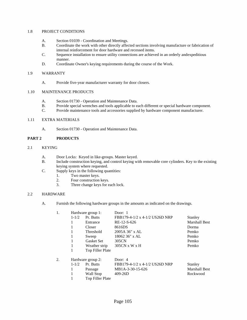
Page 105
1.8 PROJECT CONDITIONS A. Section 01039 - Coordination and Meetings. B. Coordinate the work with other directly affected sections involving manufacture or fabrication of
internal reinforcement for door hardware and recessed items. C. Sequence installation to ensure utility connections are achieved in an orderly and expeditious
manner. D. Coordinate Owner's keying requirements during the course of the Work. 1.9 WARRANTY A. Provide five-year manufacturer warranty for door closers. 1.10 MAINTENANCE PRODUCTS A. Section 01730 - Operation and Maintenance Data. B. Provide special wrenches and tools applicable to each different or special hardware component. C. Provide maintenance tools and accessories supplied by hardware component manufacturer. 1.11 EXTRA MATERIALS A. Section 01730 - Operation and Maintenance Data. PART 2 PRODUCTS 2.1 KEYING A. Door Locks: Keyed in like-groups. Master keyed. B. Include construction keying, and control keying with removable core cylinders. Key to the existing
keying system where requested. C. Supply keys in the following quantities: 1. Two master keys. 2. Four construction keys. 3. Three change keys for each lock. 2.2 HARDWARE A. Furnish the following hardware groups in the amounts as indicated on the drawings. 1. Hardware group 1: Door: 1 1-1/2 Pr. Butts FBB179-4-1/2 x 4-1/2 US26D NRP Stanley 1 Entrance RE-12-S-626 Marshall Best 1 Closer 8616DS Dorma 1 Threshold 2005A 36" x AL Pemko 1 Sweep 18062 36" x AL Pemko 1 Gasket Set 305CN Pemko 1 Weather strip 305CN x W x H Pemko 1 Top Filler Plate 2. Hardware group 2: Door: 4 1-1/2 Pr. Butts FBB179-4-1/2 x 4-1/2 US26D NRP Stanley 1 Passage MB1A-3-30-15-626 Marshall Best 1 Wall Stop 409-26D Rockwood 1 Top Filler Plate

Page 106
3. Hardware group 3: Door: 5 3 Pr. Butts FBB179-4-1/2 x 4-1/2 US26D NRP Stanley 1 Privacy MB1A-3-20-626 Marshall Best 1 Wall Stop 409-26D Rockwood 1 Top Filler Plate PART 3 EXECUTION 3.1 EXAMINATION A. Section 01039 - Coordination and Meetings: Verification of existing conditions before starting
work. B. Verify that doors and frames are ready to receive work and dimensions are as indicated on shop
drawings. C. Verify that electric power is available to power operated devices and is of the correct
characteristics. 3.2 INSTALLATION A. Install hardware in accordance with manufacturer's instructions. B. Use templates provided by hardware item manufacturer. 3.3 FIELD QUALITY CONTROL A. Section 01400 - Quality Control 01650 - Starting of Systems: Field inspection, testing, and
adjusting. B. Architectural Hardware Consultant will inspect installation and certify that hardware and
installation has been furnished and installed in accordance with manufacturer's instructions and as specified.
3.4 ADJUSTING A. Section: 01650 - Starting of Systems: Adjusting installed work. B. Adjust hardware for smooth operation.
END OF SECTION

Page 107
08720
ELECTRIC DOOR OPERATORS
PART 1 GENERAL 1.1 SUMMARY A. Provide electric trolley type sectional overhead door operator and electric rolling door operator,
where shown on the Drawings, as specified herein and as needed for a complete and proper installation.
B. Related work: 1. Documents affecting work of this Section include but are not necessarily limited to,
General Conditions, Supplementary Conditions and Sections in Division 1 of these Specifications.
1.2 SUBMITTALS A. Product data: Within 30 calendar days after the Contractor has received the Owner's Notice to
Proceed, submit: 1. Materials list of items proposed to be provided under this Section; 2. Manufacturers' specifications and other data needed to prove compliance with the
specified requirements; 3. Shop drawings showing general layout, installation, materials, construction and assembly
wiring. 4. Manufacturers' recommended installation procedures which, when approved by the
Architect, will become the basis for accepting or rejecting actual installation procedures used on the Work.
B. Upon completion of this portion of the work and as a condition of its acceptance, deliver to the owner three copies of the operation and maintenance manual.
1.3 QUALITY ASSURANCE A. Use adequate numbers of skilled workmen who are thoroughly trained and experienced in the
necessary crafts and who are completely familiar with the specified requirements and the methods needed for proper performance of the work of this Section.
B. Comply with all governmental agencies having jurisdiction in this work. C. Each operator shall have a minimum one (1) year manufacturer's warranty. 1.4 DELIVERY, STORAGE, AND HANDLING A. Comply with pertinent provisions of Section 01620. PART 2 PRODUCTS AND MATERIAL 2.1 REQUIRED ATTRIBUTES A. Trolley Type: 1. Motor - 115/230V single phase, 1/2 hp instant reversing with automatic reset thermal
overload. Equal to Overhead Door Corp. Model “RSX”. 2. Reversing Contactor - Heavy duty, electrically and mechanically interlocked. 3. Limit Switches - Adjustable rotary type synchronized with door operation. 4. Control Circuit - 24 volt class 2, three button, OPEN-CLOSE-STOP. 5. Reduction - Primary-V-belt, secondary-chain and sprocket. 6. Clutch - Adjustable disc friction type. 7. Brake - Solenoid actuated drum type.
Page 108
8. Provisions for the connection of a 2-wire monitored photo electric eye cell system. 2.2 OTHER MATERIALS
A. Provide other materials, not specifically described but required for a complete and proper installation, as selected by the Contractor subject to the approval of the Architect.
B. Provide a one-button remote for each garage door opener. PART 3 EXECUTION 3.1 SURFACE CONDITIONS A. Examine the areas and conditions under which work of this Section will be performed. Correct
conditions detrimental to timely and proper completion of the Work. Do not proceed until unsatisfactory conditions are corrected.
3.2 INSTALLATION A. Install the work of this section in strict accordance with the manufacturer's recommendations and
shop drawings and in accordance with pertinent requirements of governmental agencies having jurisdiction.
B. Electrical contractor will run electricity to the electric door operator. Final connection to the door operator shall be the responsibility of the electric door operator installer.
3.3 ADJUSTMENTS AND INSTRUCTIONS A. Upon completion of the installation, carefully inspect each component and verify that all items have
been installed in the proper location, adequately anchored and adjusted to achieve optimum operation.
B. Demonstrate to the owner, operation and maintenance procedures.
END OF SECTION
Page 109
08800
GLAZING PART 1 GENERAL 1.1 SECTION INCLUDES A. Glass and glazing for hollow metal work, windows, glazed walls and doors. B. Glass for cabinet doors and view panels. 1.2 RELATED SECTIONS A. Section 08111 - Standard Steel Doors: Glazed doors. B. Section 08360 - Sectional Overhead Doors. C. Section 10800 - Toilet and Bath Accessories: Mirrors. 1.3 REFERENCES A. ANSI Z97.1 - Safety Performance Specifications and Methods of Test for Safety Glazing Used in
Buildings. B. ASTM C669 - Glazing Compounds for Back Bedding and Face Glazing of Metal Sash. C. ASTM C804 - Use of Solvent-Release Type Sealants. D. ASTM C1036 - Flat Glass. E. ASTM C1048 - Heat-Treated Flat Glass - Kind HS, Kind FT Coated and Uncoated Glass. F. ASTM C1172 - Laminated Architectural Safety Glass. G. ASTM E84 - Surface Burning Characteristics of Building Materials. 1.4 QUALITY ASSURANCE A. Installer Qualifications: Company specializing in performing the work of this section with
minimum three years experience. 1.5 ENVIRONMENTAL REQUIREMENTS A. Section 01600 - Material and Equipment: Environmental conditions affecting products on site. B. Do not install glazing when ambient temperature is less than 50 degrees F. C. Maintain minimum ambient temperature before, during and 24 hours after installation of glazing
compounds. 1.6 WARRANTY A. 01700 - Warranties and Bonds. B. Provide a five (5) year warranty to include coverage for sealed glass units from seal failure,
interpane dusting or misting and replacement of it. C. Provide a five (5) year warranty to include coverage for delamination of laminated glass and
replacement of it. PART 2 PRODUCTS 2.1 FLAT GLASS MATERIALS A. Float Glass (Type FG-A): Clear.
Page 110
PART 3 EXECUTION 3.1 EXAMINATION A. Section 01039 - Coordination and Meetings: Verification of existing conditions before starting
work. B. Verify that openings for glazing are correctly sized and within tolerance. C. Verify that surfaces of glazing channels or recesses are clean, free of obstructions that may impede
moisture movement; weeps are clear and ready to receive glazing. 3.2 PREPARATION A. Clean contact surfaces with solvent and wipe dry. B. Seal porous glazing channels or recesses with substrate compatible primer or sealer. C. Prime surfaces scheduled to receive sealant. D. Perform installation in accordance with ASTM C804 for solvent release sealants. 3.3 INSTALLATION - INTERIOR WET/DRY METHOD (TAPE AND SEALANT) A. Cut glazing tape to length and install against permanent stops, projecting 1/16 inch above sight line. B. Place setting blocks at 1/4 points with edge block no more than 6 inches from corners. C. Rest glazing on setting blocks and push against tape to ensure full contact at perimeter of pane or
unit. D. Install removable stops, spacer shims inserted between glazing and applied stops at 24 inch
intervals, 1/4 inch below sight line. E. Trim protruding tape edge. 3.4 CLEANING A. Remove glazing materials from finish surfaces. B. Remove labels after Work is complete. C. Clean glass and adjacent surfaces. 3.5 PROTECTION OF FINISHED WORK A. After installation, mark pane with an 'X' by using removable plastic tape or paste. Do not mark heat
absorbing or reflective glass units.
END OF SECTION
Page 111
09260
GYPSUM BOARD SYSTEM
PART 1 GENERAL 1.1 SECTION INCLUDES A. Gypsum board and joint treatment. 1.2 RELATED SECTIONS A. Section 06112 - Framing and Sheathing: Building wood framing system. B. Section 07212 - Batt Insulation: Thermal insulation. 1.3 REFERENCES A. ASTM C36 - Standard Specification for Gypsum Wallboard. B. ASTM C79 - Standard Specification for Gypsum Sheathing Board. C. ASTM C442 - Standard Specification for Gypsum Backing Board and Coreboard. D. ASTM C475 - Standard Specification for Joint Compound and Joint Tape for Finishing Gypsum
Board. E. ASTM C630 - Standard Specification for Water-Resistant Gypsum Backing Board. F. ASTM C645 - Standard Specification for Non-Load (Axial) Bearing Steel Studs, Runners (Track)
and Rigid Furring Channels for Screw Application of Gypsum Board. G. ASTM C754 - Standard Specification for Installation of Steel Framing Members to Receive Screw-
Attached Gypsum Board. H. ASTM C840 - Standard Specification for Application and Finishing of Gypsum Board. I. ASTM C1002 - Standard Specification for Steel Drill Screws for the Application of Gypsum Board
or Metal Plaster Bases. J. ASTM E119 - Standard Test Methods for Fire Tests of Building Construction and Materials. K. GA-201 - Using Gypsum Board for Walls and Ceilings. L. GA-214 - Recommended Specification: Levels of Gypsum Board Finish. M. GA-216 - Recommended Specifications for the Application and Finishing of Gypsum Board. N. GA-600 - Fire Resistance Design Manual. O. UL - Fire Resistance Directory. 1.4 QUALITY ASSURANCE A. Perform Work in accordance with ASTM C840. B. Applicator Qualifications: Company specializing in performing the work of this section with
minimum three years experience. PART 2 PRODUCTS 2.1 GYPSUM BOARD MATERIALS A. Standard Gypsum Board: ASTM C36; 5/8 inch thick, maximum available length in place; ends
square cut, tapered edges. B. Fire Rated Gypsum Board: ASTM C36; fire resistive type, UL or WH rated; 5/8 inch thick,
maximum available length in place; ends square cut, tapered edges. C. Moisture Resistant Gypsum Board: ASTM C630; 5/8 inch thick, maximum available length in
place; ends square cut, tapered edges.
Page 112
2.2 ACCESSORIES A. Corner Beads: Metal. B. Edge Trim: GA-201 and GA-216; Type LC exposed reveal bead. C. Joint Materials: ASTM C475; reinforcing tape, joint compound, adhesive and water. D. Textured Finish Materials: Latex based texturing material, containing fine aggregate. E. Fasteners: ASTM C1002, Type S12 and GA-216. PART 3 EXECUTION 3.1 EXAMINATION A. Section 01039 - Coordination and Meetings: Verification of existing conditions before starting
work. B. Verify that site conditions are ready to receive work and opening dimensions are as indicated on
drawings. 3.2 GYPSUM BOARD INSTALLATION A. Install gypsum board in accordance with GA-201, GA-216 and GA-600. B. Erect single layer standard gypsum board horizontal, with ends and edges occurring over firm
bearing. C. Erect single layer fire rated gypsum board vertically, with edges and ends occurring over firm
bearing. D. Use screws when fastening gypsum board to metal furring or framing. 3.3 JOINT TREATMENT A. Tape, fill, and sand exposed joints, edges and corners to produce smooth surface ready to receive
finishes. B. Feather coats on to adjoining surfaces so that camber is maximum 1/32 inch. 3.4 TOLERANCES A. Maximum Variation of Finished Gypsum Board Surface from True Flatness: 1/8 inch in 10 feet in
any direction.
END OF SECTION
Page 113
09511
SUSPENDED ACOUSTIC CEILINGS PART 1 GENERAL 1.1 SECTION INCLUDES A. Suspended metal grid ceiling system and perimeter trim. B. Acoustic tile. 1.2 REFERENCES A. ASTM C635 - Manufacture, Performance and Testing of Metal Suspension Systems for Acoustical
Tile and Lay-in Panel Ceilings. B. ASTM C636 - Installation of Metal Ceiling Suspension Systems for Acoustical Tile and Lay-in
Panels. C. ASTM E580 - Application of Ceiling Suspension Systems for Acoustical Tile and Lay-in Panels in
Areas Requiring Seismic Restraint. D. ASTM E1264 - Classification of Acoustical Ceiling Products. E. UL - Fire Resistance Directory. 1.3 SYSTEM DESCRIPTION A. Installed System: Conform to UL Design for ceiling and floor assembly. B. Suspension System: Rigidly secure acoustic ceiling system including integral mechanical and
electrical components with maximum deflection of 1:240. 1.4 SUBMITTALS FOR REVIEW A. Section 01300 - Submittals: Procedures for submittals. B. Shop Drawings: Indicate grid layout and related dimensioning, junctions with other work or ceiling
finishes, interrelation of mechanical and electrical items related to system. C. Product Data: Provide data on metal grid system components and acoustic units. D. Samples: Submit two full size samples illustrating material and finish of acoustic units. 1.5 QUALITY ASSURANCE A. Conform to CISCA requirements. B. Grid Manufacturer: Company specializing in manufacturing the Products specified in this section
with minimum three years experience. C. Acoustic Unit Manufacturer: Company specializing in manufacturing the Products specified in this
section with minimum three years experience. 1.6 REGULATORY REQUIREMENTS A. Conform to applicable code for fire rated assembly and combustibility requirements for materials. 1.7 ENVIRONMENTAL REQUIREMENTS A. Section 01600 - Material and Equipment: Environmental conditions affecting products on site. B. Maintain uniform temperature of minimum 60 degrees F and maximum humidity of 65 percent
prior to, during and after acoustic unit installation.

Page 114
1.8 PROJECT CONDITIONS A. Section 01039 - Coordination and Meetings. B. Sequence work to ensure acoustic ceilings are not installed until building is enclosed, sufficient heat
is provided, dust-generating activities have terminated and overhead work is completed, tested and approved.
C. Install acoustic units after interior wet work is dry. 1.9 EXTRA MATERIALS A. Section 01730 - Operation and Maintenance Data. B. Provide 64 sq. ft. of extra tile to Owner. PART 2 PRODUCTS 2.1 SUSPENSION SYSTEM MATERIALS A. Fire Rated Grid: ASTM C635, intermediate duty, listed by UL for use in a one-hour assembly,
exposed T. B. Grid Materials: Commercial quality cold rolled steel with galvanized coating. C. Exposed Grid Surface Width: 15/16 inch with reveal. D. Grid Finish: color as selected. E. Accessories: Stabilizer bars, clips, splices, perimeter moldings, and hold down clips required for
suspended grid system. F. Support Channels and Hangers: Galvanized steel; size and type to suit application, seismic
requirements and ceiling system flatness requirement specified. 2.2 ACOUSTIC UNIT MATERIALS A. Acoustic Panels: ASTM E1264, conforming to the following: 1. Size: 24 x 24 inches. 2. Thickness: 5/8 inches. 3. Composition: Mineral. 2.3 ACCESSORIES A. Touch-up Paint: Type and color to match acoustic and grid units. PART 3 EXECUTION 3.1 EXAMINATION A. Section 01039 - Coordination and Meetings: Verification of existing conditions before starting
work. B. Verify that layout of hangers will not interfere with other work. 3.2 INSTALLATION - LAY-IN GRID SUSPENSION SYSTEM A. Install suspension system in accordance with ASTM C636 and as supplemented in this section. B. Install system in accordance with ASTM E580. C. Install system capable of supporting imposed loads to a deflection of 1/240 maximum. D. Lay out system to a balanced grid design with edge units no less than 50 percent of acoustic unit
size. E. Install after major above ceiling work is complete. Coordinate the location of hangers with other
work.

Page 115
F. Hang suspension system independent of walls, columns, ducts, pipes and conduit. Where carrying members are spliced, avoid visible displacement of face plane of adjacent members.
G. Where ducts or other equipment prevent the regular spacing of hangers, reinforce the nearest affected hangers and related carrying channels to span the extra distance.
H. Do not support components on main runners or cross runners if weight causes total dead load to exceed deflection capability. Support fixture loads by supplementary hangers located within 6 inches of each corner or support components independently.
I. Do not eccentrically load system, or produce rotation of runners. J. Perimeter Molding: 1. Install edge molding at intersection of ceiling and vertical surfaces with continuous gasket. 2. Use longest practical lengths. 3. Miter corners. 4. Provide at junctions with other interruptions. K. Form expansion joints as required. Form to accommodate plus or minus 1-inch movement.
Maintain visual closure. L. Install light fixture boxes constructed of gypsum board above light fixtures in accordance with UL
assembly requirements and light fixture ventilation requirements. 3.3 INSTALLATION - ACOUSTIC UNITS A. Install acoustic units in accordance with manufacturer's instructions. B. Fit acoustic units in place, free from damaged edges or other defects detrimental to appearance and
function. C. Lay directional patterned units one way with pattern parallel to longest room axis. Fit border trim
neatly against abutting surfaces. D. Install units after above ceiling work is complete. E. Install acoustic units level, in uniform plane, and free from twist, warp and dents. F. Cutting Acoustic Units: 1. Cut to fit irregular grid and perimeter edge trim. 2. Cut square reveal edges to field cut units. 3. Double cut and field paint exposed edges of tegular units. G. Install hold-down clips to retain panels tight to grid system within 20 ft. of an exterior door. 3.4 ERECTION TOLERANCES A. Section 01400 - Quality Control: Tolerances. B. Maximum Variation from Flat and Level Surface: 1/8 inch in 10 feet. C. Maximum Variation from Plumb of Grid Members Caused by Eccentric Loads: 2 degrees.
END OF SECTION
Page 116
09900
PAINTING PART 1 GENERAL 1.1 SECTION INCLUDES A. Surface preparation. B. Field application of paint. 1.2 RELATED SECTIONS A. Section 05500 - Metal Fabrications: Shop primed items. 1.3 REFERENCES A. ASTM D16 - Standard Terminology Relating to Paint, Varnish, Lacquer and Related Products. B. ASTM D4442 - Standard Test Methods for Direct Moisture Content Measurement of Wood and
Wood-Base Materials. C. NACE (National Association of Corrosion Engineers) - Industrial Maintenance Painting. D. NPCA - Guide to U.S. Government Paint Specifications; National Paint and Coatings Association. E. PDCA - Architectural Specifications Manual; Painting and Decorating Contractors of America. F. SSPC - Steel Structures Painting Manual; Steel Structures Painting Council. 1.4 DEFINITIONS A. Conform to ASTM D16 for interpretation of terms used in this section. 1.5 SUBMITTALS FOR REVIEW A. Section 01300 - Submittals: Procedures for submittals. B. Samples: 1. Submit two paper chip samples, 2 x 4 inches in size illustrating range of colors and
textures available for each surface finishing product scheduled. 1.6 QUALITY ASSURANCE A. Manufacturer Qualifications: Company specializing in manufacturing the Products specified in this
section with minimum three years documented experience. B. Applicator Qualifications: Company specializing in performing the work of this section with
minimum three years experience. 1.7 DELIVERY, STORAGE AND PROTECTION A. Section 01600 - Material and Equipment: Transport, handle, store and protect products. B. Deliver products to site in sealed and labeled containers; inspect to verify acceptability. C. Container Label: Include manufacturer's name, type of paint, brand name, lot number, brand code,
coverage, surface preparation, drying time, cleanup requirements, color designation and instructions for mixing and reducing.
D. Paint Materials: Store at minimum ambient temperature of 45 degrees F and a maximum of 90 degrees F, in ventilated area, and as required by manufacturer's instructions.

Page 117
1.8 ENVIRONMENTAL REQUIREMENTS A. Section 01600 - Material and Equipment: Environmental conditions affecting products on site. B. Do not apply materials when surface and ambient temperatures are outside the temperature ranges
required by the paint product manufacturer. C. Do not apply exterior coatings during rain or snow or when relative humidity is outside the
humidity ranges required by the paint product manufacturer. D. Minimum Application Temperatures for Latex Paints: 45 degrees F for interiors; 50 degrees F for
exterior, unless required otherwise by manufacturer's instructions. E. Minimum Application Temperature for Varnish Finishes: 65 degrees F for interior or exterior,
unless required otherwise by manufacturer's instructions. F. Provide lighting level of 80 ft candles measured mid-height at substrate surface. 1.9 PROJECT CONDITIONS A. Section 01039 - Coordination and Meetings. B. Sequence application to the following: 1. Do not apply finish coats until paintable sealant is applied. 2. Back prime wood trim before installation of trim. 1.10 EXTRA MATERIALS A. Section 01730 - Operation and Maintenance Data. B. Supply 1 gallons of each color, type and surface texture; store where directed.
C. Label each container with color, type, texture and room locations in addition to the manufacturer's label.
PART 2 PRODUCTS 2.1 MATERIALS A. Coatings: Ready mixed, except field-catalyzed coatings. Prepare pigments: 1. To a soft paste consistency, capable of being readily and uniformly dispersed to a
homogeneous coating. 2. For good flow and brushing properties. 3. Capable of drying or curing free of streaks or sags. B. Accessory Materials: Linseed oil, shellac, turpentine, paint thinners and other materials not
specifically indicated but required to achieve the finishes specified; commercial quality. C. Patching Materials: Latex filler. D. Fastener Head Cover Materials: Latex filler. 2.2 FINISHES A. Refer to finish schedule on drawings for surface finish. 2.3 BRAND OF PAINT A. Sherwin-Williams or equal. PART 3 EXECUTION

Page 118
3.1 EXAMINATION A. Section 01039 - Coordination and Meetings: Verification of existing conditions before starting
Work. B. Verify that surfaces and substrate conditions are ready to receive Work as instructed by the product
manufacturer. C. Examine surfaces scheduled to be finished prior to commencement of work. Report any condition
that may potentially affect proper application. D. Test shop applied primer for compatibility with subsequent cover materials. E. Measure moisture content of surfaces using an electronic moisture meter. Do not apply finishes
unless moisture content of surfaces is below the following maximums: 1. Plaster and Gypsum Wallboard: 12 percent. 2. Masonry, Concrete and Concrete Unit Masonry: 12%. 3. Interior Wood: 15 percent, measured in accordance with ASTM D4442. 4. Exterior Wood: 15 percent, measured in accordance with ASTM D4442. 5. Concrete Floors: 8 percent. 3.2 PREPARATION A. Surface Appurtenances: Remove or mask electrical plates, hardware, light fixture trim, escutcheons
and fittings prior to preparing surfaces or finishing. B. Surfaces: Correct defects and clean surfaces that affect work of this section. C. Marks: Seal with shellac those that may bleed through surface finishes. D. Impervious Surfaces: Remove mildew by scrubbing with solution of tri-sodium phosphate and
bleach. Rinse with clean water and allow surface to dry. E. Gypsum Board Surfaces: Fill minor defects with filler compound. Spot prime defects after repair. F. Uncoated Steel and Iron Surfaces: Remove grease, mill scale, weld splatter, dirt and rust. Where
heavy coatings of scale are evident, remove by [hand] [power tool] wire brushing or sandblasting; clean by washing with solvent. Apply a treatment of phosphoric acid solution, ensuring weld joints, bolts and nuts are similarly cleaned. Spot prime paint after repairs.
G. Shop Primed Steel Surfaces: Sand and scrape to remove loose primer and rust. Feather edges to make touch-up patches inconspicuous. Clean surfaces with a solvent. Prime paint bare steel surfaces.
H. Metal Doors Scheduled for Painting: Prime metal door top and bottom edge surfaces. 3.3 APPLICATION A. Apply products in accordance with manufacturer's instructions. B. Do not apply finishes to surfaces that are not dry. Allow applied coats to dry before next coat is
applied. C. Apply each coat to uniform appearance. Apply each coat of paint slightly darker than preceding
coat unless otherwise approved. D. Sand wood surfaces lightly between coats to achieve required finish. E. Vacuum clean surfaces of loose particles. Use tack cloth to remove dust and particles just prior to
applying next coat. 3.4 CLEANING A. Collect waste material that may constitute a fire hazard, place in closed metal containers and
remove daily from site. 3.5 SCHEDULE - EXTERIOR SURFACES A. Steel - Unprimed: 1. One coat of alkyd primer. 2. Two coats of alkyd enamel, gloss.
Page 119
B. Steel - Shop Primed: 1. Touch-up with zinc chromate primer. 2. Two coats of alkyd enamel, gloss. C Steel - Galvanized: 1. One coat galvanize primer. 2. Two coats of alkyd enamel, gloss. 3.6 SCHEDULE - INTERIOR SURFACES A. Interior Gypsum Drywall 1. One coat of vinyl latex primer sealer. 2. Two coats of latex eggshell enamel. B. Steel - Unprimed: 1. One coat of alkyd primer. 2. Two coats of alkyd enamel, gloss. C. Steel - Shop Primed: 1. Touch-up with zinc chromate primer. 2. Two coats of alkyd enamel, gloss.
END OF SECTION
Page 120
10800
TOILET AND BATH ACCESSORIES
PART 1 GENERAL 1.1 SECTION INCLUDES A. Toilet and shower room accessories. 1.2 RELATED SECTIONS A. Section 05500: In wall framing and plates for support of accessories. B. Section 06112: Placement of concealed anchor devices and placement of backing plate
reinforcement. C. Section 08800 - Glazing: Other mirrors. 1.3 REFERENCES A. ASTM A123 - Standard Specification for Zinc (Hot-Dip Galvanized) Coatings on Iron and Steel
Products. B. ASTM A653/A653M - Standard Specification for Steel Sheet, Zinc-Coated (Galvanized) or Zinc-
Iron Alloy-Coated (Galvanealed) by the Hot-Dip Process. C. ASTM B456 - Standard Specification for Electrodeposited Coatings of Copper Plus Nickel Plus
Chromium and Nickel Plus Chromium. D. ASTM C1036 - Standard Specification for Flat Glass. E. FS DD-M-411C -- Mirrors, Glass. 1.4 COORDINATION A. Section 01039 - Coordination and Meetings. B. Coordinate the work with the placement of internal wall reinforcement and reinforcement of toilet
partitions to receive anchor attachments. PART 2 PRODUCTS 2.1 MATERIALS A. Accessories - General: Shop assembled, free of dents and scratches and packaged complete with
fittings, steel anchor plates, adapters and anchor components for installation. 1. Grind welded joints smooth. 2. Fabricate units made of metal sheet of seamless sheets, with flat surfaces. B. Keys: Provide 3 keys for each accessory to Owner. C. Fasteners, Screws, and Bolts: Hot dip galvanized, tamper-proof type. D. Expansion Shields: Fiber, lead or rubber as recommended by accessory manufacturer for
component and substrate. 2.2 FINISHES A. Chrome/Nickel Plating: ASTM B456, Type SC 2, satin finish, unless otherwise noted. B. Baked Enamel: Pretreat to clean condition, apply one coat of primer and minimum two coats epoxy
baked enamel. C. Galvanizing for Items other than Sheet: ASTM A123 to 1.25 oz/sq yd. Galvanize ferrous metal and
fastening devices. D. Shop Primed Ferrous Metals: Pretreat and clean, spray apply one coat primer and bake.
Page 121
E. Back paint components where contact is made with building finishes to prevent electrolysis. 2.3 TOILET ROOM ACCESSORIES A. Toilet Paper Dispenser: Double roll surface mounted bracket type, chrome-plated zinc alloy
brackets eccentric-shaped plastic spindle for 1/2 revolution delivery designed to prevent theft of tissue roll.
B. Paper Towel Dispenser: Surface Mounted automatic. Four D-sized batteries. Non-perforated paper towels. Provide one roll of towels. Equal to Bobrick B-72974.
C. Soap Dispenser: Wall mounted translucent high-impact plastic container, 1.5-gallon capacity. To be located by the service sinks.
D. Mirrors: Stainless steel framed, 6 mm thick float glass, abrasion-resistant coated mirror. 1. Size: As indicated on drawings. 2. Frame: 0.05 inch channel shapes, with mitered and welded and ground corners, and
tamperproof hanging system; No.4 bright annealed finish. 3. Backing: Full-mirror sized, minimum 0.03 inch galvanized steel sheet and nonabsorptive
filler material. E. Grab Bars: Stainless steel, 1-1/4 inches outside diameter, minimum 0.05 inch wall thickness,
nonslip grasping surface finish, exposed flange mounting; 1-1/2 inches clearance between wall and inside of grab bar. Length and Configuration: As indicated on drawings.
F. Hat and Coat Hook: Equal to Bobrick B-682. 1. Wall Mounting Flange: 2”x 2” bright polished stainless steel. 2. Hook: 1” wide x 6-1/4” high, bright polished stainless steel with 3” projection. G. Soap Dispenser: Equal to Bobrick B-2111 surface mounted soap dispenser for liquid and lotion
soaps and detergents. 1. Minimum Capacity: 40 ounces. 2. Surface mounted type 304 stainless steel with satin finish. 3. Corrosion resistant valve. PART 3 EXECUTION 3.1 EXAMINATION A. Section 01039 - Coordination and Meetings: Verification of existing conditions before starting
work. B. Verify exact location of accessories for installation. C. Verify that field measurements are as indicated on product data. 3.2 PREPARATION A. Deliver inserts and rough-in frames to site for timely installation. B. Provide templates and rough-in measurements as required. 3.3 INSTALLATION A. Install accessories in accordance with manufacturers' instructions. B. Install plumb and level, securely and rigidly anchored to substrate. C. Mounting Heights and Locations: As required by accessibility regulations.
END OF SECTION

Page 122
15050
MATERIALS AND METHODS
PART 1 GENERAL 1.1 OPERATION PRIOR TO ACCEPTANCE A. When any equipment is operable, and it is to the advantage of the Contractor to operate the
equipment, he may do so provided that he properly supervises the operation, and retains full responsibility for the equipment operated. Before final acceptance by the owner, the Contractor shall properly clean the equipment, install clean filter media, make all required adjustments and complete all punch list items.
1.2 WARRANTY A. Warrant to Owner that materials, equipment, and workmanship provided under this Division of the
Specifications will be free from defects for a period of one year from the date of acceptance by Owner. Additional equipment warranty requirements are stated in other sections of the specifications.
PART 2 PRODUCTS 2.1 MATERIALS A. Products are to be new and free from defects, and are to be installed by competent specialist for
each trade in accordance with the manufacturer's recommendations. Materials or equipment not meeting these standards, or the acceptance of the Engineer, may be rejected and will be replaced at no additional costs to the owner.
PART 3 EXECUTION 3.1 PIPING INSTALLATION A. Conceal piping in pipe chases, walls, furred spaces and above ceiling, unless otherwise indicated. B. Should any condition arise which would cause piping or ductwork to be exposed in finished areas,it
will be called to the architect/owner's attention immediately and corrected in accordance withthe architect/owner's instructions.
3.2 HANGERS AND SUPPORTS A. Provide and install per ANSI Standards SP-58 and SP-69. B. Adequately support pipes throughout the buildings, both horizontal and vertical. C. Hanger Schedule PIPE HANGER SERVICE SIZE TYPE GRINNELL NO. Uninsulated 2" & smaller Split Ring 108 with 114 Steel Uninsulated 2" & smaller Ring CT 99 Copper

Page 123
Cast Iron All Clevis 590 Soil Pipe Insulated 4" & smaller Clevis 260 with shield Steel Insulated 2" & smaller Clevis CT 65 Copper D. Multiple or Trapeze Hangers” Steel channels with angles or unistrut spacers and hanger rods. E. Wall Support 2 1/2 inch and over: Welded steel bracket and wrought steel clamp. F. Vertical Support: Steel riser clamp. G. Provide copper plated hangers and supports for copper piping or provide sheet plastic tape
wrapping between hanger or support and piping. H. Equivalent products of Fee and Mason or Elcen are acceptable substitutes for the Grinnell hangers
specified. I. Maximum horizontal pipe hanger support spacing and minimum rod diameter for rigid rod hangers
(see chart). J. Install hangers to provide minimum 1/2-inch clear space between finished covering and adjacent
work. K. Place a hanger within one foot of each horizontal elbow. L. Support horizontal soil pipe near each hub, with 10 feet maximum spacing between hangers. M. Support PVC piping per manufacturer's recommendations. 3.3 ELECTRICAL WIRING OF MOTORS AND EQUIPMENT A. Follow manufacturer's published directions in the delivery, storage, protection, installation, piping
and wiring and start-up of equipment and materials. 3.4 ACCESS PANELS AND DOORS A. Install access panels and doors for concealed equipment and valves. 3.5 TESTS A. Field test mechanical equipment furnished and installed under this Contract as required by the
Engineer Tests. B. Perform tests required by governing authorities, in addition to tests specified in individual Sections. C. Complete final installation and testing 14 days prior to Contract Substantial Completion Date. D. All pipe work shall be tested at the pressure equal to the design working pressure of the pipe for the
intended service and maintain this pressure for not less than two hours with not more than 1% drop in pressure.
E. Notify architect/owner of any test failures. Submit weekly pipe test log listing service; section tested, initial and final pressure, time and temperature.
END OF SECTION
Page 124
15400
PLUMBING SYSTEMS PART 1 GENERAL 1.1 SUMMARY A. Section Includes: 1. Water piping. 2. Sanitary drainage. 3. Condensate piping. 4. Testing. B. Comply with other Division 15 Sections, as applicable. Refer to other Divisions for coordination of
work. 1.2 SUBMITTALS A. Make submittals for all products specified in the specification. PART 2 PRODUCTS 2.1 MATERIALS A. Water Piping Above Grade, Type "L" hard drawn, seamless copper water tube, ASTM B88 and
Federal Specification WW-T-799. Joined with wrought copper pressure fittings, ANSI B16.22. Make joints using "lead free" solder and a non-corrosive paste-type flux. Core solder is not allowed. Solder will be solid string or wire type. Where soldered copper piping is connected to threaded brass piping, use a cast brass adaptor.
B. Water Piping Below Grade, Type "K" hard drawn, seamless copper water tube, ASTM B88 and Federal Specification WW-T-799. Joined with wrought copper pressure fittings, ANSI B16.22. Make joints using "lead free" solder and a non-corrosive paste-type flux. Core solder is not allowed. Solder will be solid string or wire type. Where soldered copper piping is connected to threaded brass piping, use a cast brass adaptor.
C. Make piping connections to fixtures and equipment with chrome-plated seamless brass tube, ASTM B-125 and Federal Specification WW-T0791. No ferrous piping or materials are allowed in water piping smaller than 4 inches.
2.2 SANITARY DRAINAGE A. Sanitary Drainage lines (Soil, Waste and Vent): Cast iron soil pipe and fittings, coating inside and
outside, ASTM A74 and Federal Specification WW-P-401. Label with Cast Iron Soil Pipe Institutes' "Mark of Quality and Permanence". Weights of pipe are required by code for location and duty. Joints shall be fabricated by use of "Push-On" type gasketed joints (above or below ground) or "No-Hub" mechanical joints (above ground only). Where permitted by local codes, PVC-DWV Plastic Schedule 40, NSF Seal CS-272 may be used for sanitary drainage pipes (soil, waste, and vent), with solvent-welded joints.
2.3 VALVES A. Valves for Domestic Water Piping Systems: Nibco S580 or equal. 2.4 PRESSURE REDUCING VALVE A. When the water system static pressure is greater than 75 PSI, furnish and install a pressure-reducing
valve ahead of all fixtures and located in an accessible place. Set pressure at 50 PSI downstream of backflow preventer. Contractor to verify supply pressure.

Page 125
2.5 COMMERCIAL TYPE WATER HAMMER ARRESTERS A. Provide commercial type water hammer arrester on hot and cold water supplies as generally
indicated, with precise location and sizing to be in accordance with PD1-WH201. B. Water hammer arresters, where concealed, shall be accessible by means of access doors or
removable panels. C. Water hammer arresters shall be in accordance with PD1-WH201, as furnished by Watt, Josam or
equal. D. Vertical capped pipe columns will not be permitted. 2.6 BACKFLOW PREVENTER A. Provide a Watts #909 reduced pressure backflow preventer for the domestic water service. 2.6 PLUMBING FIXTURES A. Provide and install fixtures as shown on plans. PART 3 EXECUTION 3.1 PIPING INSTALLATION A. Install piping neatly and parallel with or perpendicular to lines of the structure. Install pipe hangers
to maintain accurately aligned piping systems, adequately supported both laterally and vertically. Install horizontal soil, waste, and vent pipe with a grade of 1/4" per foot where possible and not less than 1/8" per foot. Where practicable, connect two or more vents together and extend as one vent through roof. Make vent connections to stacks by appropriate use of 45 wyes, long sweep quarter bends, sixth, eighth or sixteenth bends, except that sanitary tees may be used on the vertical stacks.
B. Extend condensate drain piping from units with condensate discharge. C. Install drains at all low points and vents at high points in water distribution system. 3.2 PIPING A. Refer to Section 15700 for insulation requirements. 3.3 PIPE TESTS A. Test water piping before installing equipment and before insulation is applied, using specified
methods and conditions. Subject piping to test for not less than 24 hours under inspection by the Engineer. Make necessary replacements and repairs and repeat tests until entire system is accepted as satisfactory. Work includes testing equipment. After installation of equipment, operate systems; clean out scale, dirt, oil, waste and foreign matter, and correct additional leaks. Test underground piping prior to backfilling.
B. Test plumbing drainage systems under 10 foot static head. Test water systems under 150 PSIG hydrostatic pressure.
C. Flush system thoroughly of dirt and foreign matter, then fill with water treated with 50 ppm of
chlorine. During filling process, open valves and faucets several times to assure treatment of entire system. Leave treated water in system for 24 hours after which time system may be flushed; if residual chlorine is not less than 10 ppm, repeat flushing. After sterilization, receive approval by regulatory agency on samples of water in system.
END OF SECTION
Page 126
15410
COMPRESSED AIR PIPING PART 1 GENERAL 1.1 SUMMARY A. Section Includes: 1. High Pressure Air System (Over 100 p.s.i) 2. Low Pressure Air System (Below 100 p.s.i) B. Work includes but is not limited to the following: 1. Piping 2. Valves 3. Test Procedures 1.2 QUALITY ASSURANCE A. Regulatory Requirements 1. Compressed Air Piping: Compressed air piping shall meet the requirements of ANSI
B31.1. 2. Rotating Equipment. Fully guard couplings, motor shafts, gears and other exposed rotating
or rapidly moving parts in accordance with OSHA 29 CFR 1920.219. Provide rigid and suitable secured guard parts readily removable without disassembling guarded unit.
3. Welding: Safety in welding and cutting of pipe shall conform to ANSI Z49.1 B. Standard Products 1. Materials and equipment shall be the standard products of manufacturers regularly
engaged in the manufacture of such products and shall essentially duplicate items that have been in satisfactory use for at least 2 years prior to bid opening.
PART 2 PRODUCTS 2.1 HIGH PRESSURE AIR PIPING A. High Pressure Pipe and Fittings 1. Piping shall be black steel, schedule 40 seamless, ASTM A106 or A53. 2. Fittings shall be schedule 40 but weld fittings for pipe 2 1/2 inches and larger and 300#
malleable iron fittings for pipe 2 inches and smaller. B. Low Pressure Pipe and Fittings 1. Piping shall be black steel, schedule 40 ASTM A53. 2. Fittings shall be schedule 40, but weld fittings for pipe 2 1/2 inches and larger and 150#
malleable iron fittings for pipe 2 inches and smaller. 2.2 VALVES AND SPECIALTIES A. Compressed Air Piping Valves 1. 150 pound class bronze gate valves, Type II, Class B, or globe Valves. Checkvalves: Lift
or swing type. Ball Valves: Valves shall be full-port type with bolted body cap. Ball and stem shall be hard chrome-plated carbon steel.
B. Pressure Gauges 1. Steel or brass case, and non-shatterable safety glass, and a pressure blowout back to
prevent glass from flying out in case of an explosion. Gauges shall have a 3 1/2 inch minimum diameter dial and a dial range of approximately twice working pressure. Provide gauge cock for each pressure gauge.

Page 127
C. Provide Pressure Reducing Valves 1. Spring loaded type, with nominal pressure rating of not less than inlet system pressure
indicated. Provide pressure-reducing valves capable of being adjusted to specified flow and pressure, and suitable for intended service.
D. Hose connectors shall be all brass, of the size and type indicated on the drawings. E. Filter and/or lubricator shall be suitable for the intended flow and pressure. F. Traps shall be rated at not less than the system pressure and shall be capable of draining water and
other liquids from the system. G. Pressure reducing valves shall be pressure rated of not less than the system inlet pressure. The
outlet pressure shall be capable of adjustment to specified flow and pressure. H. Air hose shall be rated at nominal 100 psi and shall have a rubber or neoprene tube with 2 ply
construction with abrasion resistant cover. PART 3 EXECUTION 3.1 INSTALLATION A. Installation of Compressed Air System 1. Accomplish installation of air piping and equipment in accordance with ANSI B31.1 and
only by competent personnel. The compressors and equipment shall be installed under the supervision of the compressor manufacturer’s representative. The compressor and associated equipment shall be installed in accordance with the manufacturer’s recommendations
2. Work material and equipment into complete, convenient, and economical system or systems; and provide apparatus, parts, materials and accessories that are necessary to accomplish this result. Piping shall follow general arrangement shown, cut accurately to measurements established for work by the Contractor, and work into place without springing or forcing. Install piping and equipment within buildings entirely out of the way of lighting fixtures and doors, windows and other openings. Run overhead piping in buildings in the most inconspicuous positions. Make provision for expansion and contraction of pipelines. Install in accordance with the best method of practice. Do not conceal piping until it has been inspected, tested and approved. Protect materials and equipment from the weather.
3. Install compressors on pad type isolators as specified in paragraph 15250-2.02-B. B. Drainage and Flexibility 1. Compressed air piping shall be free of unnecessary pockets and pitched approximately 3
inches per 100 feet in the direction of flow to low points. Where pipes must be sloped so that condensate flows in opposite direction to air flow, slope 6 inches per 100 feet or greater. Provide flexibility by use of fittings, loops and offsets in piping. Install branches at top of a main to prevent carryover of condensate and foreign matter.
2. Provide traps to eliminate liquids from the system. C. Cleaning 1. Before assembly and installation, clean piping, fittings, valves, unions and other
components of the systems of dirt, oil and other contaminants. Piping for oil free systems shall be oil-free prior to and during installation.

Page 128
D. Anchoring, Guiding, and Supporting Piping 1. Anchor and support piping in a manner such that expansion and contraction will take place
in direction desired and prevent vibration by use of vibration dampeners and prevent undue strains on equipment served. Fabricate hangers used for support of piping 2-inch nominal pipe size and larger to permit adequate adjustment after erection while still supporting load. Use wall brackets where pipes are adjacent to walls or other vertical surfaces that may be used for supports. Furnish and install supports to adequately carry weight of lines. Provide inserts and sleeves in concrete where necessary. Design and fabrication of hanger, supports and anchors shall conform to ANSI B31.1. Space pipe supports at intervals specified in Section 15050 Materials and Methods.
E. Pressure reducing valves, filters, lubricators, quick couplers and other accessories shall be provided
as indicated on the drawings. 3.2 TESTING A. General Requirements 1. The Contractor shall perform all field tests and shall provide everything required for the
tests. Make tests under the direction and subject to approval of the Engineer. 2. Qualified personnel shall test compressed air systems, pressurize each piping system
individually and check to assure that there are no cross connections between different systems prior to operational tests. Test all piping to one and one half times the normal system operating pressure.
END OF SECTION
Page 129
15440
PLUMBING FIXTURES PART 1 GENERAL 1.1 SUMMARY A. Section Includes: 1. Plumbing fixtures and trim. B. Related Sections: 1. Refer to other Divisions for coordination of work. 1.2 SUBMITTALS A. Product Data: Submit manufacturer's descriptive literature for all products specified. PART 2 PRODUCTS 2.1 FITTINGS AND PIPING A. Provide brass fittings and piping in connection with plumbing fixtures; polished chrome-plated
where exposed to view. B. Provide tight-fitting wall or floor escutcheons of chrome-plated brass wherever pipes pass through
floors, walls or ceilings. C. Provide required water, waste, soil, and vent connections to plumbing fixtures and equipment,
together with fittings, supports, fastening devices, cocks, valves and traps, leaving all in complete working order.
2.2 FIXTURES A. Provide new plumbing fixtures, first quality, free from mars or chips. Sufficient means to support
each fixture in an adequate and rigid manner that permits no perceptible movement of fixture by manually applied forces. Fixtures to be standard products as manufactured by American Standard, Crane, Eljer or Kohler. The space between fixtures and floor or walls to be sealed with silicone sealant.
B. Each fixture shall be complete with required trim, and exposed piping and trim shall be polished chrome-plated brass. Each fixture shall be furnished with stop valves having metal-to-metal seats.
C. Provide for each lavatory and sink, a flow-limiting device that will limit flow to not more than 3 g.p.m. Devices shall be integral with fixture trim, wherever possible and shall be products of the fixture trim Manufacturer in all cases.
D. Provide plumbing fixtures as scheduled on Drawings. E. See Specification Section 15410 - Compressed Air Piping, 2.2 Valves and Specialties. PART 3 EXECUTION 3.1 INSTALLATION A. Plumbing fixtures and equipment shall be set in place at locations indicated on the Drawings,
leveled and connected. Fixtures shall be protected from damage during construction. B. Installation procedures shall be in accordance with these Specifications and the Manufacturer's
directions.
Page 130
3.2 ADJUSTING AND CLEANING A. Prior to final acceptance, inspect faucets, flush valves, stop valves, and similar devices, to
determine that they operate properly and discharge the proper quantities of water. Correct any deficiencies as directed by the Engineer.
B. Clean fixtures, trim and accessories of foreign materials, including labels.
END OF SECTION

Page 131
15441
PRE-CAST TRENCH DRAINAGE SYSTEM
PART 1 GENERAL 1.1 SUMMARY A. Provide Pre-Cast Trench Drainage system where shown on the drawings, as specified herein and as
designed and recommended by the manufacturer, complete in place, tested and approved, including but not necessarily limited to:
1. Complete system design by a qualified manufacturer representative including but not necessarily limited to shop drawings, design criteria and engineering data of a total drainage system.
2. Complete in place pre-cast trench drainage system complying with the manufacturers design and recommended installation procedures.
B. Related Work 1. Documents affecting work of this section include, but are not necessarily limited to,
General Conditions, Supplementary Conditions and Sections in Division 1 of the Specifications.
2. Section 02730 Sanitary Sewerage System. Section 03300 Cast-In-Place Concrete. 1.2 SUBMITTALS A. Comply with pertinent provisions of Section 01340. B. Design data: Within 45 calendar days after the contractor has received the Owner's Notice to Proceed, submit: 1. Complete design drawings and specifications fully describing the materials and methods
proposed to be used. When approved by the architect/owner, will become the basis for accepting or rejecting actual installation procedures used on the work.
2. Design calculation and necessary engineering data. 3. Data that the design and calculations have been produced in compliance with these
specifications and by a qualified representative of the manufacturer. C. Product data: Within 45 calendar days after the contractor has received the Owner's Notice to
Proceed, submit: 1. Materials list of items proposed to be provided under this section. 2. Manufacturer's recommended installation procedures. When approved by the
architect/owner, will become the basis for accepting or rejecting actual installation procedures used on the work.
1.3 QUALITY ASSURANCE A. Use adequate numbers of skilled workmen who are thoroughly trained and experienced in the
necessary crafts and who are completely familiar with the specified requirements and method needed for proper performance of the work of this section.
1.4 DELIVERY, STORAGE AND HANDLING A. Comply with pertinent provisions of Section 01620. PART 2 PRODUCTS 2.1 A. Acceptable Manufacturers:
Page 132
1. The design is based on use of ACO K100S Quicklock Trench Drain System manufactured and designed by ACO Polymer Products Inc., 12080 Ravenna Road, Chardon, Ohio 44024, 1-800-543-4764, and terminology used may include references to proprietary products of that company or approved equal. Construe such references as establishing only the quality of workmanship and materials to be provided under this section, and not as limiting competition.
2. Other manufacturers approved in advance by the architect/owner. B. Except as otherwise approved by the architect/owner, provide the pre-cast trench drainage system
having the following attributes: 1. Sloped trench drain channels a. Channels shall be pre-cast b. Sloped or neutral and interlocking c. Incorporating polyesters or vinylester resins and formulated aggregates d. Recassed for grating lock down device e. Unit width - 5.1" inches f. Internal width - 4.0 inches g. Unit depth - 5.6 to 12.4 inches h. Compressive strength - 14,500 psi i. Flexural strength - 2,900 psi j. Built in slope - 0.6% k. Water absorption rate not to exceed 1% 2. Slotted grating; heavy duty with load classification "C", ADA Designed. See Plumbing
Fixture Schedule on plans. 3. Catch basins of like materials and construction having knockouts for plumbing
connections. 4. Grate locking devices. 5. Other parts and accessories, including outlet and caps, pipe outlets, inlet and caps as
required based on the design requirements. 2.2 OTHER MATERIAL A. Provide other materials, not specifically described but required for a complete and proper
installation. PART 3 EXECUTION 3.1 SURFACE CONDITIONS A. Examine the areas and conditions under which work of this section will be performed. Correct
conditions detrimental to timely and proper completion of the work. Do not proceed until unsatisfactory conditions are corrected.
3.2 SITE PREPARATION A. Excavate the area for channel placement wide and deep enough to accommodate the channels and
appurtenances as recommended by the manufacturer. 3.3 INSTALLATION A. Coordinate as required with other trades to assure proper and adequate provision in the work of
these trades for interface with the work of this section. B. Install work of this section in strict accordance with the approved design and shop drawings,
pertinent requirements of governmental agencies having jurisdiction and the manufacturer's recommended installation procedures as approved by the architect/owner.
C. Upon completion of the installation, make all required arrangements, conduct all required tests and make all required changes or corrections as needed.
END OF SECTION
Page 133
15490
NATURAL GAS PIPING PART 1 GENERAL 1.1 SUMMARY A. Section includes: 1. Natural gas piping. B. Comply with Division 15 as applicable. Refer to other Divisions for coordination of work. PART 2 PRODUCTS 2.1 NATURAL GAS PIPING (ABOVE GRADE) A. Piping to be black steel, standard weight. Schedule 40 ASTM A120. Installation shall conform to
NFPA 54 and applicable local codes. 2.2 GAS VALVES A. Valves 2" and smaller shall be 125 psi bronze or cast iron body, flat head cock, with bronze plug, as
manufactured by Crane, Jenkins or Powell. 2.3 GAS SERVICE REGULATORS A. Furnish and install regulators as needed for a complete and proper installation as manufactured by
Rockwell or Fisher. PART 3 EXECUTION 3.1 INSTALLATION A. Mechanical Contractor to extend gas piping to all gas appliances and install valved, dirt leg, and
union at each appliance. B. Pipe welders to be certified and bear evidence of certification 30 days prior to commencing work on
this project. 3.2 NATURAL GAS PIPING - TESTING A. After completion of work, the entire system will be tested. B. For each line intended to be operated at pressure of less than 1 PSIG, give leak test a 3 pressure of
25 PSIG for 2 hours, or as required by local authority if more stringent. C. For each line intended to be operated at a pressure of 1 PSIG and above, give leak test at a pressure
of 100 PSIG for 2 hours, or as required by local authority if more stringent.
END OF SECTION

Page 134
15500
HEATING, VENTILATING AND AIR CONDITIONING
PART 1 GENERAL 1.1 SUMMARY A. Provide heating, ventilating, and air conditioning systems where shown on the Drawings, as
specified herein and as needed for a complete and proper installation including but not necessarily limited to:
1. Heating and Central Air Condenser Unit. 2. Air conditioning supply and return ductwork system with grilles and diffusers. 3. Gas-fired, ceiling-hung Unit Heaters 4. Temperature control system including low-voltage wiring. 5. Acoustical and thermal insulation of ducts. 6. Engineering and design, refer to drawings. B. Related work: 1. Documents affecting work of this Section include, but are not necessarily limited to,
General Conditions, Supplementary Conditions and Sections in Division 1 of these Specifications.
1.2 SUBMITTALS A. Comply with pertinent provisions of Section 01340. B. Product data: Within 30 calendar days after the Contractor has received the Owner's Notice to Proceed, submit: 1. Manufacturers catalogs, samples and other items needed to fully demonstrate the quality of
the proposed materials and equipment. C. Record drawings: 1. Comply with pertinent provisions of Section 01720. 2. Include a copy of the Record Drawings in each copy of the operation and maintenance
manual described below. D. Upon completion of this portion of the Work, and as a condition of its acceptance, deliver to the
Architect two copies of an operation and maintenance manual compiled in accordance with the provisions of Section 01730 of these Specifications.
1.3 QUALITY ASSURANCE A. Use adequate numbers of skilled workmen who are thoroughly trained and experienced in the
necessary crafts and who are completely familiar with the specified requirements and the methods needed for proper performance of the work of this Section.
B. Without additional cost to the Owner, provide such other labor and materials as are required to complete the work of this Section in accordance with the requirements of governmental agencies having jurisdiction, regardless of whether such materials and associated labor are called for elsewhere in these Contract Documents.
C. Provide minimum 1-year manufacturer's warranty on all units. 1.4 DELIVERY, STORAGE AND HANDLING A. Comply with pertinent provisions of Section 01620.

Page 135
PART 2 PRODUCTS 2.1 DUCTWORK A. For exhaust systems and for the heating, ventilating, and air conditioning systems, provide
galvanized sheet metal ducts fabricated and installed to pertinent ASHRAE and SMACNA standards or to the requirements of governmental agencies having jurisdiction, whichever requirement is more stringent.
B. Size the ducts for pressure drop of 0.1" H20 per 100 feet. C. Seal all duct seams, transverse and longitudinal, air tight with 6 ox canvas secured in place with
"WC800" or equal duct sealing compound, an approved lagging adhesive or duct tape. 2.2 FLEXIBLE DUCT A. Provide factory fabricated insulated low-pressure flexible duct with the following attributes: 1. Zinc-coated spring steel helix, with 1" thick fiberglass insulation, sheathed in a seamless
vapor barrier jacket. 2. Interior fire-resistive coated to prevent fiber erosion; 3. Straight run sound absorption of 3 db per ft, and 5 db per ft sound absorption at 45 degree
bends; 4. Composite assembly, including insulation and vapor barrier, meeting Class 1 requirements
of flame spread of 25 or less and smoke developed of 50 or less as set forth in NFPA Bulletin 90-A and bearing UL label as an air duct.
B. Provide flexible duct in fully extended condition, free from sags and kinks. 1. Use only the minimum length required to make the connection. 2. Do not exceed 8'-0" in length. 3. Where horizontal support is required, provide at least 3/4" wide banding material hangers
at not more than 36" centers. 4. Make joints and connections with 1/2" wide positive locking steel straps. C. Acceptable products: 1. Insulated low pressure flexible duct "Type S-181" manufactured by Glass Insulation Co.,
Los Angeles. 2. For toilet exhaust or return air connectors and runouts, aluminum flexible ducts such as
"Flexmaster" or "Van-guard" may be used if acceptable to the governmental agencies having jurisdiction.
2.3 INSULATION A. General: 1. Provide materials complying with NFPA Bulletin 90-A, as determined by UL method
NFPA 225-ASTM E84, and complying with the governing code, with flame spread rating under 25 and smoke developed rating under 50.
2. Where vapor barriers are used, provide intact and continuous throughout. 3. Acceptable manufacturers: a. Owens/Corning Fiberglass; b. Manville c. Certainteed. B. All supply ducts: 1. Insulate supply ducts with 1" thick fiberglass blanket such as Fiberglas "FRK ED-100," or
equal approved in advance by the Architect. 2. Insulate return ducts with 3/4-pcf 1" thick fiberglass duct wrap blanket.

Page 136
C. Acoustical duct liner: For ducts exposed to the weather and for supply ducts from supply fan to first branch ducts:
1. Line with one of the following 1" thick materials: a. CSG No. 300, coated; b. PPG 3 pcf; c. Superine (or Textrafine) Fiberglass PF-615; d. Manville 3 pcf Micortex coated duct liner. 2. Apply duct liner with coated side facing air stream and secured to the sheet metal with
"ED104" adhesive or with mechanical clips recommended by the manufacturer. 3. Make joints tightly butted and heavily sized with "Lag-gas" or "Arabolt Lagging
Adhesive," assuring continuity of surfaces. 2.4 AIR OUTLETS A. Ceiling diffusers: 1. Provide Hart & Cooley or Approved Equal, in size, capacity and pattern noted on the
Drawings. 2. Provide insulated adaptor boxes above each diffuser neck to permit connection of flexible
duct. B. Grilles: Provide Hart & Cooley or Approved Equal in size, capacity and pattern noted on drawings. C. Provide factory-applied or site-applied black coating on the inside of all air outlets and connecting
plenums. D. Provide sponge rubber under all flanges. 2.5 VIBRATION ISOLATION AND FLEXIBLE CONNECTIONS A. At ducts to equipment, provide vent-fabric flexible connections with a minimum of 6" full length
and approved by the governmental agencies having jurisdiction. B. Provide additional sound isolation as required to limit the noise level in conditioned space to a
maximum of NC-40. 2.6 HEATING AND CENTRAL AIR UNIT A. Install High Efficiency, Direct Vent, Condensing Upflow Gas Furnaces with necessary
appurtenances, per HVAC Schedule. See Construction Documents, equal to Carrier. B. Install High Efficiency Air Conditioners with necessary appurtenances, per Split Systems HVAC
Units Schedule sheet 26 of 29, equal to Carrier. C. Install Carrier Model TSTATCCPAC01-B 7 day programmable thermostats, or approved equals,
per manufacturer's instructions and specifications. D. Location of units per drawings E. Vent furnace unit per Manufacturer's instructions and specifications and as per drawings. 2.7 UNIT HEATERS A. Unit Heater. Furnish gas fired, propeller fan and unit heaters as manufactured by one of the
following companies: Crane, Reznor, National, Pearless, Carrier, Tran Bryant, or equal in the capacity shown on the plans. Units shall be A.G.A. certified, completely assembled and be operationally tested before shipment from factory.
B. Unit Heater Exchanger. Shall be stainless steel seam or arc welded with tubes and headers not lighter than 20 gauge thickness. Draft diverters shall be aluminized steel or equal. Electrical characteristics as required.
C. Burners. The burners shall be of cast iron or stainless steel construction that will give quiet, smooth ignition throughout the length of the burner. They shall be equipped with adjustable air shutters to regulate flame characteristics for maximum efficiency. All burners shall be individually removable.
Page 137
D. Pilot. Shall be of the intermittent pilot systems type using gas only when the system calls for heat, is lit by high voltage capacitive discharge spark, turns off automatically when demand for heat is satisfied or flame is lost. If flame is lost, unit shuts off main valve, re-starts ignition sequence.
E. Wiring. Units shall be factory wired for high limit and fan control. Fan motor shall be 115 volt, single phase, 60 cycle totally enclosed with overload protection.
F. Gas Valve. The gas valve shall be standard type 24-volt single phase, 60 cycle arranged for 100% safety shut off on main and pilot burner. 115/24-volt transformer to be supplied with unit heater and factory wired on low voltage side to gas valve.
2.8 PIPING A. For refrigerant piping, provide Type "L" copper, refrigerant grade, with wrought copper fittings,and
with joints thoroughly cleaned prior to soldering. 2.9 AUTOMATIC TEMPERATURE CONTROL A. Provide a system of temperature control with the attributes listed below. 1. Include thermostats, sensors, temperature controllers, and air piping as requiring for a
complete and operable system compatible with approved Heating and Central Air Unit. 2. Provide devices calibrated and adjusted with the actual operating conditions. 2.10 OTHER MATERIALS A. Provide other materials, not specifically described but required for a complete and proper
installation, as selected by the Contractor subject to the approval of the Architect. PART 3 EXECUTION 3.1 SURFACE CONDITIONS A. Examine the areas and conditions under which work of this Section will be performed. Correct
conditions detrimental to timely and proper completion of the Work. Do not proceed until unsatisfactory conditions are corrected.
3.2 COORDINATION A. Coordinate as required with other trades to assure proper and adequate provision in the work of
those trades for interface with the work of this Section. 3.3 EQUIPMENT INTERFACE A. Provide all required shutoff valves, unions and final connections of piping to the work of this
Section. B. For electrically operated equipment, verify the electrical characteristics actually available for the
work of this Section and provide equipment meeting those characteristics. 3.4 PAINTING A. Paint inside of all air outlets and connecting plenums with one coat of black paint or provide all
such items factory preprinted. 3.5 INSULATION A. Wrap insulation firmly around ductwork, covering all surfaces including standing seams and with
all joints lapped at least 2".

Page 138
B. Securely fasten the insulation in place with 16 gauge soft annealed black or galvanized wire spaced approximately 12" on centers for straight runs and 3" on centers for elbows and fittings.
C. Take special care to avoid excessive stretching and compressing and to achieve securing at lapped sections where possible.
3.6 INSTRUCTIONS A. Upon completion of this portion of the Work, and prior to its acceptance by the Owner, provide a
qualified engineer and fully instruct the Owner's maintenance personnel in the proper operation and maintenance of items provided under this Section.
B. Demonstrate the contents of the approved operation and maintenance manual required under Article 1.2 above.
3.7 TESTING AND ADJUSTING A. Test and adjust each piece of equipment and each system as required to assure proper balance and
operation. 1. Test and regulate ventilation and air conditioning systems to conform to the air volumes
shown on the approved design drawings. 2. Make tests and adjustments in apparatus and ducts for securing the proper volume and face
distribution of air for each grille and ceiling outlet. 3. Where required, provide pulleys for fans at no additional cost to the Owner and set to drive
the fans at the speed needed to give the indicated volume. 4. For each system, take the following data in tabulated form: a. Air volumes at all supply return and exhaust outlets; b. Total c.f.m. supplied; c. Total c.f.m. returned; d. Total static pressure at each fan and at each system; e. Motor speed, fan speed and input ampere rating for each fan. B. Submit two sets of test and balance reports to the Architect for approval. C. Eliminate noise and vibration, and assure proper function of all controls, maintenance of
temperature and operation in accordance with the approved design. D. Secure required approval from governmental agencies having jurisdiction.
END OF SECTION

Page 139
15887
CARBON MONOXIDE EXHAUST SYSTEMS
PART 1 GENERAL 1.1 SUMMARY A. Provide carbon monoxide system where shown on the Drawings, as specified herein complete in
place, tested and approved, including but not necessarily limited to: 1. Exhaust fans 2. Ductwork and duct fittings 3. Inlet fittings 4. Accessories B. Related work: 1. Documents affecting work of this section include, but are not necessarily limited to,
General Conditions, Supplementary Conditions and Sections in Division 1 of these Specifications.
1.2 SUBMITTALS A. Comply with pertinent provisions of Section 01340. B. Product data: Within 35 calendar days after the Contractor has received the Owner's "Notice to
Proceed" submit: 1. Materials list of items proposed to be provided under this section; 2. Manufactures literature and data indicating rated capacities, dimensions weights and
pocket loading, accessories, electrical requirements and wiring diagrams. 3. Manufactures recommended installation procedures, when approved by the
Architect/Owner, will become the basis for accepting or rejecting actual installation procedures used on the work
4. Operation data: Include instructions for fan lubrication, motor and drive replacement, and spare parts list
1.3 Quality Assurance A. Use adequate numbers of skilled workmen who are thoroughly trained and experienced in the
necessary crafts and who are completely familiar with the specified requirements and methods needed for proper performance of the work of this section.
B. Performance Ratings: Conform to AMCA 300 1.4 Delivery, Storage and Handling A. Comply with the pertinent provisions of the Section 01620 PART 2 PRODUCTS A. Acceptable Manufactures: 1. The design criteria is based on the use of products manufactured by Car-Mon Products
Inc., 1225 Davis Rd., Eligin, Il. 60123-1317 or approved equal. B. Except as otherwise approved by the Architect/Owner, provided a complete Carbon Monoxide
Exhaust System having the following equipment and accessories. 1. Exhaust fan; a. Shall be single inlet, single width, arrangement 10 shall have backward inclined
fan wheel with single thickness flat blades.

Page 140
b. The fan wheel shall be statically balanced before assembly any required balance weight shall be welded to the outside of the shroud or backplate, no weights are to be installed in the blade air stream.
c. The bearings shall be of the pillow block type with cast steel frame and be bolted to the structural angle supports that form part of the fan base.
d. The scroll and side sheets of the fan housing and the spun inlet cone shall be fabricated of cold rolled steel of 12 gauge and shall be joined through continuous welding. The inlet cone shall be bolted to the housing using a minimum of 8 studs welded to the housing.
e. The fan base and inlet support shall be fabricated of 12 gauge cold rolled steel. Bearing supports shall be fabricated of cold rolled steel angle, 3/16" thick, welded to the side of the lease. All seams shall be continuous welded. The motor base shall be 10 ga. cold rolled steel, and have adjustable positions. Apply caulking to mating surfaces of the inlet cone and the fan housing, and the fan housing and fan lease.
f. The V-Belt drive shall be the adjustable type, the variable pitch sheave shall be factory set at the position to provide the specified capacity. All drives for the fans having 1 HP and larger motors shall have 2 V-Belts all fans shall be provided with a belt guard, with tachometer hole, enclosing sheave and belts.
g. All surfaces of centrifugal having diameters of 22 1/4" and less shall receive a Heresite air dry phenolic resinous coating. Fans having larger diameter shall be similarly coated except all exterior surfaces which shall receive an air dry machinery coating.
h. Fans shall be tested to measure "total frequency" vibration at each bearing. Fans having an average reading over 3 mils deflection will not be accepted Furnish reports indicating compliance.
2. Ceiling Suspension Platform a. Fan platform shall be of heavy duty all welded construction, using 1 ½” x 1 ½” x
3/16” angle iron for the suspension platform. The suspension platform shall incorporate a 3" x 4.1 lb. base channel for vibration rails and 4 holes for suspension rods. Car-Mon Products Inc. CSP/VR
3. Inlet Taper and Discharge Flexible Connection a. Fans shall be equipped with flexible connectors on the incoming and outgoing
sides of the fans. Car-Mon Products Inc. Use Fan Model 14 when providing 2 to 3 reels. Use Fan Model 25 when providing 4 reels. Use fan model as recommended for one reel.
4. Back Draft Damper a. Furnish an automatic back draft damper of all aluminum construction. The blades
shall be linked together to provide simultaneous movement and shall have nylon bearings and felt blade edge seals.
5. Flexible Tubing a. 25' x 6" Drop flexible tubing shall be abrasion resistant constructed of fire
retardant fabric, cured to resist exhaust temperatures up to 665 degrees F. The tubing shall have as external steel-spring wire reinforced spiral. Provide RCT-6 adapters.
6. Retractable Hose Reel a. Provide at each exhaust tubing drop automatic retractable hose reel assembly, as
furnished by the manufacturer. Car-Mon Products Inc. Model # TSR-S32. 2.2 OTHER MATERIAL A. Provide other materials not specifically described but required for a complete and proper
installation.
Page 141
PART 3 EXECUTION A. SURFACE CONDITIONS 1. Examine the areas and conditions under which the work of this Section will be performed
correct conditions detrimental to timely and proper completion of the work. Do not proceed until conditions are corrected.
B. INSTALLATION 1. Coordinate as required with the other trades to assure proper and adequate provisions in
the work of these trades for interface with the work of the Section. 2. Install work in this Section in strict accordance with the Drawings, pertinent requirements
of governmental agencies having jurisdiction and the manufacturer's recommended installation procedures as approved by the Architect/Owner.
3. Upon completion of the installation, make all required arrangements, conduct all required test and make all required changes or corrections as needed.
END OF SECTION
Page 142
15990
TESTING AND BALANCING
PART 1 GENERAL 1.1 RELATED DOCUMENTS A. This section specifies the requirements and procedures for total mechanical systems testing,
adjusting and balancing. Requirements include measurement and establishment of the fluid quantities of the mechanical system as required to meet design specifications, recording and reporting the results and operation of all systems to demonstrate satisfactory performance to the Owner.
B. Test, adjust and balance the following mechanical systems: 1. Supply, return and exhaust air systems 2. Hydronic heating and cooling systems. 3. Verify temperature control system operation. C. This Section does not include: 1. Specifications for materials for patching mechanical systems. 2. Specifications for materials and installation of adjusting and balancing devices. If devices
must be added to achieve proper adjusting and balancing, refer to the respective system sections for materials and installation requirements.
3. Requirements and procedures for piping and ductwork systems leakage tests. 1.2 DEFINITIONS A. Systems testing, adjusting, and balancing is the process of checking and adjusting all the building
environmental systems to produce the design objectives. It includes: 1. The balance of air and water distribution 2. Adjustment of total system to provide design quantities 3. Electrical measurement 4. Verification of performance of all equipment and automatic controls 5. Sound and vibration measurement B. Test: To determine quantitative performance of equipment. C. Adjust: To regulate the specified fluid flow rate and air patterns at the terminal equipment (e.g.
reduce fan speed, throttling). D. Balance: To proportion flows within the distribution system (sub mains, branches and terminals)
according to specified design quantities. E. Procedure: Standardized approach and execution of sequence of work operations to yield
reproducible results F. Report Forms: Test data sheets arranged for collecting test data in logical order for submission and
review. These data sheets should also form the permanent record to be used as the basis for required future testing, adjusting and balancing.
G. Terminal: The point where the controlled fluid enters or leaves the distribution system. There are
supply inlets on water terminals, supply outlets on air terminals, return outlets on water terminals, and exhaust or return inlets on air terminal such as registers, grilles, diffusers, louvers and hoods.
H. Main: Duct or pipe containing the system’s major or entire fluid flow.

Page 143
I. Submain: Duct or pipe containing part of the system’s capacity and serving two or more branch mains.
J. Branch Main: Duct or pipe serving two or more terminals. K. Branch: Duct or pipe serving a single terminal. 1.3 SUBMITTALS A. Agency Data: 1. Submit proof that the proposed testing, adjusting, and balancing agency meets the
qualifications specified below. The firm or individuals performing the work herein specified may be the installing firm or individuals or may be separate and independent firm or individuals employed by the contractor but in either case the personnel performing the work shall be qualified and certified as specified.
B. Engineer and Technicians Data: 1. Submit proof that the proposed testing, adjusting, and balancing agency meets the
qualifications specified below. The firm or individuals performing the work herein specified may be the installing firm or individuals or may be a separate and independent firm or individuals employed by the Contractor, but in either case the personnel performing the work shall be qualified and certified as specified.
C. Procedures and Agenda: Submit a synopsis of the testing adjusting and balancing procedures and
agenda proposed to be used for this project. D. Maintenance Date: Submit maintenance and operating data that includes how to test, adjust and
balance the building system. Include this information in maintenance data specified in Division 15 - Basic Mechanical Requirements.
E. Sample Forms: Submit sample forms, if other than those standard forms prepared by the AABC or
NEBB are proposed. F. Certified Reports: Submit testing, adjusting, and balancing reports bearing the seal and signature of
the Test and Balance Engineer. The reports shall be certified proof that the systems have been tested, adjusted, and balanced in accordance with the referenced standards; are an accurate representation of how the systems have been installed; are a true representation of how the systems are operating at the completion of the testing, adjusting, and balancing procedures; and are an accurate record of all final quantities measured, to establish normal operating values of the systems. Follow the procedures and form as specified below:
G. Reports: Upon completion of testing, adjusting, and balancing procedures, prepare reports on the
approved forms. Reports may be hand written, but must be complete, factual, accurate and legible. Submit 3 complete sets of reports. Only 2 complete sets of draft reports will be returned.
H. Report Format: Report forms shall be those standard forms prepared by the referenced standard for
each respective item and system to be tested, adjusted and balanced. Bind report forms complete with schematic systems diagrams and other data in reinforced, vinyl, three-ring binders. Provide binding edge labels with the project identification and a title descriptive of the contents. Divide the contents of the binder into the below listed divisions, separated by divider tabs.
1. General Information and Summary 2. Air Systems 3. Temperature Control Systems

Page 144
I. Report Contents: Provide the following minimum information, forms and data: 1. General Information and Summary: Inside cover sheet to identify testing, adjusting and
balancing agency, contractor, Owner, Architect, Engineer and Project. Include addresses, and contact names a telephone numbers. Also include a certification sheet containing the seal and name, address, telephone number and signature of the Certified Test and Balance Engineer. Include in this division a listing of the instrumentation used for the procedures along with the proof of calibration.
2. The remainder of the report shall contain appropriate forms containing as a minimum, the information indicated on the standard report forms prepared by the AABC and NEBB, for each respective item and system to accompany each respective report form. The report shall contain the following information, and all other data resulting from the testing, adjusting and balancing work:
3. All nameplate and specification data for all pumps, air handling equipment and motors. 4. Inlet water and outlet water temperatures of each heating and cooling element. 5. Water pressure drop through each heating and cooling coil. 6. Operating suction and discharge pressure and final total discharge head for each pump. 7. Water flow readings at all pumps and coils. 8. Actual metered running amperage for each phase of each motor on all pumps and air
handling equipment. 9. Actual metered voltage at each pump and each piece of air handling equipment (phase to
phase for all phases) 10. Static pressure for each piece of air handling equipment and at each location in ductwork
system where static pressure controllers are located. 11. Fan RPM for each piece of air handling equipment. 12. Total actual DCM being handled by each piece of air handling equipment. 13. Entering and leaving air temperature of all air handling unit heating coils and cooling
coils. 14. Actual CFM of systems by rooms. 1.4 CERTIFICATION A. Agency Qualifications: 1. Employ the services of a certified testing, adjusting and balancing agency meeting the
qualifications specified below, to be the single source of responsibility to test, adjust and balance the building mechanical systems, identified above, to produce the design objectives. Services shall include checking installations for conformity to design, measurement and establishment of the fluid quantities of the mechanical systems as required to meet design specifications, recording and reporting the results and operation of all systems to demonstrate satisfactory performance to the Owner.
2. The testing, adjusting, and balancing agency certified by National Environmental Balancing Bureau (NEBB) or Associated Air Balance Council (AABC) in those testing and balancing disciplines required for this project and having at least one person certified by NEBB or AABC as a Test and Balance Engineer.
B. Codes and Standards
1. NEBB: “Procedural Standards for Testing, Adjusting, and Balancing of Environmental Systems”. Or
2. AABC: “National Standards for Total System Balance”, And 3. ASHRAE: “ASHRAE Handbook”, 1984 Systems Volume, Chapter 37, Testing, Adjusting
and Balancing. C. Pre-balancing Conference: Prior to beginning of the testing, adjusting, and balancing procedures,
schedule and conduct a conference with the Architect/Engineer and representatives of installers of the mechanical system. The objective of the conference is final coordination and verification of system operation and readiness for testing, adjusting and balancing.
Page 145
1.5 PROJECT CONDITIONS A. Systems Operation: System shall be fully operational and clean prior to beginning procedures. 1.6 SEQUENCING AND SCHEDULING A. Test, adjust and balance the air systems before Hydronic, steam and refrigerant systems. B. Test, adjust, and balance air conditioning systems during summer season and heating systems
during winter season, including at least a period of operation at outside conditions within 5 deg. F. Wet bulb temperature of maximum summer design condition and within 10 deg. F. Dry bulb temperature of minimum winter design condition. Take final temperature readings during seasonal operation.
PART 2 PRODUCTS Not Applicable PART 3 EXECUTION 3.1 PRELIMINARY PROCEDURE FOR AIR SYSTEM BALANCING A. Before operating the system, perform these steps: 1. Walk the system from the system air handling equipment to terminal units to determine
variations of installation from design. 2. Check filters for cleanliness and to determine if they are the type specified. 3. Check dampers (both volume and fire) for correct and locked position. Check automatic
operating and safety controls and devices to determine that they are properly connected, functioning and at proper operating set point.
4. Check automatic control dampers to determine that they are functioning properly, that they will close tightly and those they will open and close smoothly without binding or backlash.
5. Prepare report test sheets for both fans and outlets. Obtain manufacturer’s outlet factors and recommended procedures for testing. Prepare a summation of required outlet volumes to permit a cross check with required fan volumes.
6. Determine best locations in main and branch ductwork for most accurate duct traverses. 7. Place outlet dampers in the full open position. 8. Prepare schematic diagrams of system “as-built” ductwork and piping layouts to facilitate
reporting. 9. Lubricate all motors and bearings. 10. Check fan belt tension. 11. Check fan rotation. 3.2 MEASUREMENTS A. Provide all required instrumentation to obtain proper measurements, calibrated to the tolerances
specified in the referenced standards. Instruments shall be properly maintained and protected against damage.
B. Provide instruments meeting the specifications of the referenced standards. C. Use only those instruments that have the maximum field measuring accuracy and are best suited to
the function being measured. D. Apply instrument as recommended by the manufacturer. E. Use instruments with minimum scale and maximum subdivision and with scale ranges proper for
the value being measured.
Page 146
F. When averaging values, take a sufficient quantity of readings that will result in a repeatability error of less that 5 percent. When measuring a single point, repeat readings until 2 consecutive identical values are obtained.
G. Take all readings with the eye at the level of the indicated value to prevent parallax. H. Use pulsation dampeners where necessary to eliminate error involved in estimating average of
rapidly fluctuating readings. I. Take measurements in the system where best suited to the task. 3.3 PERFORMANCE TESTING, ADJUSTING, AND BALANCING A. Perform testing and balancing procedures on each system identified, in accordance with the detailed
procedures outlined in the referenced standards. Balancing of the air systems and hydronic systems shall be achieved by adjusting the automatic controls, balancing valves, dampers, air terminal devices and the fan/motor drives within each system.
B. Cut insulation, ductwork and piping for installation of test probes to the minimum extent necessary
to allow adequate performance of procedures. C. Patch insulation, ductwork and hosing, using materials identical to those removed. D. Seal ducts and piping, and test for and repair leaks. E. Seal insulation to re-establish integrity of the vapor barrier. F. Mark equipment settings, including damper control positions, valve indicators, fan speed control
levers and similar controls and devices, to show final settings. Mark with paint or other suitable, permanent identification materials.
G. Retest, adjust and balance systems subsequent to significant system modifications and resubmit test
results. 3.4 RECORD AND REPORT DATA A. Record all data obtained during testing, adjusting, and balancing in accordance with, and on the
forms recommended by the referenced standards and as approved on the sample report forms. B. Prepare report of recommendations for correcting unsatisfactory mechanical performances when
system cannot be successfully balanced. 3.5 DEMONSTRATION A. Training: 1. Train the Owner’s maintenance personnel on trouble shooting procedures and testing,
adjusting and balancing procedures. Review with the Owner’s personnel, the information contained in the Operating and Maintenance Data specified in Division 15.
2. Schedule training with Owner through Engineer with at least 7 days prior notice.
END OF SECTION

Page 147
16100
ELECTRICAL WORK
16101 GENERAL A. Requirements of the conditions of the contract and Instruction to Bidders, and General Conditions,
apply to all work of this Section. B. Provide complete electrical service where shown on the drawings, as specified herein, and as
needed for a complete and proper installation including, but not necessarily limited to: 1. Panelboards as needed. 2. Branch circuit wiring, in conduit for lighting, receptacles, junction boxes and motors. 3. Hangers, anchors, sleeves, chases, supports, for fixtures and other electrical material and
equipment in association therewith. 4. Lighting fixtures and lamps. 5. Wiring system, in conduit, for equipment and control provided under other Sections of
these specifications. 6. Other items and services required to complete the system. C. Related Work 1. Documents affecting work of this section include, but are not necessarily limited to,
General Conditions, Supplementary Conditions and Sections in Division 1 of these specifications
16102 FIELD CONDITIONS AND MEASUREMENTS A. The Electrical Contractor shall visit the site of the work and familiarize himself with all available
information concerning the structural, excavations, the location condition bearing on transportation, handling, and storage of materials. The Electrical Contractor shall make his own estimate of the facilities needed, and difficulties of execution of the contract including local conditions, availability of labor, uncertainties of weather, transportation, and other contingencies. Failure of the contractor to acquaint himself with all available information concerning these conditions will not relieve him from responsibility for estimating the difficulties and costs or successfully performing the complete work.
16103 CLEANUP A. The Electrical Contractor shall have electrical rubbish and debris removed from the premises as
directed. On completion of the electrical contract all associated debris and rubbish shall be removed from the premises.
B. All electrical equipment and materials furnished by this contractor shall be thoroughly cleaned and ready for use upon completion of the work.
16104 GUARANTEE
A. Contractor guarantees by his acceptance of the contract, that all work installed shall be free from any defects in workmanship and/or materials and that all apparatus will develop capacities and characteristics specified and that if, during a period of one year or as therefore specified, from substantial completion of work, any such defects in workmanship, materials or performance appear, he will with no cost to owner remedy such defect.
16105 CODES A. All electrical work shall be done in strict accordance with the National Electrical Code and all
regulations, laws and ordinances which may be applicable. 16106 SUBMITTALS A. Product data: Within 35 calendar days after the Contractor has received the Owner’s Notice to
Proceed, submit: 1. Materials list of items proposed to be provided under this section. 2. Manufacturer’s specifications and other data needed to prove compliance with the
specified requirements.

Page 148
3. Manufacturer’s recommended installation procedures which, when approved by the owner/architect, will become the basis for accepting or rejecting actual installation procedures used on the work.
B. Submittals shall include the following: 1. Panelboards 2. Lighting fixtures 3. Wiring devices 4. Electric cord reels C. Samples 1. When so requested by the owner/architect, promptly provide samples of items scheduled
to be exposed in the final structure. 2. When specifically so requested by the Contractor and approved by the Architect, approved
samples will be returned to the Contractor for installation on the work. D. Manuals: Upon completion of this portion of the work, and as a condition of its acceptance, deliver
to the owner/architect two copies of an operation and maintenance manual. Include with each manual.
1. Copy of the approved record documents for this portion of work. 2. Copies of all circuit directories. 3. Copies of all warranties and guarantees. 16107 QUALITY ASSURANCE A. Use adequate number of skilled workmen who are thoroughly trained and experienced in the crafts
and who are completely familiar with the specified requirements and the methods needed for proper performance of the work of this section.
B. Without additional cost to the owner, provide such other labor and materials as are required to complete the work of this section in accordance with the requirements of governmental agencies having jurisdiction, regardless of whether such materials and associated labor are called for elsewhere in these contract documents. 16108 CONDUIT A. All interior wiring above grade shall be installed in electrical metallic tubing with screw coupling
fittings. B. All interior wiring below slab shall be Galvanized Rigid Steel conduit. Schedule 40 PVC conduits
may be used if approved by Owner/Architect. If PVC is used the last two feet to point of emergence shall be Galvanized Rigid Steel conduit with grounding bushing and a grounding conductor sized according to ART. 250-95 of the National Electrical Code shall be installed.
C. Wiring in office areas shall be concealed, wiring in shop and storage areas shall be installed on surface.
D. All exterior wiring shall be in galvanized Rigid Steel Conduit. E. Type MC cable with grounding conductor or type AC cable may be used for fixture whips. 16109 WIRE AND CABLE A. Building wire and cable with 600 volt insulation shall be 98% conductivity copper unless otherwise
noted. The minimum size conductor for lighting and power shall be No. 12 AWG. The minimum size conductor for control shall be No. 14 AWG.
B. Conductors sized No. 10 and smaller shall be Type “THHN” solid or stranded as required unless
otherwise noted, sizes No. 8 and larger shall be type “THHN” stranded unless otherwise noted. C. Conductors shall be colored coded as required by governmental agencies having jurisdiction or as
required by the National Electrical Code.
Page 149
D. Contractor shall provide and install all telephone and data cable and equipment as required by the
project and per specifications sections 16930. E. Contractor shall provide and install all of the grounding and grounding field as required by this
project and per specification section 16931. F. Tele/ data cables installed above accessible ceilings may be installed without conduit. Tele/data
cables installed above non-accessible ceilings and on surface shall be in conduit. Open cables installed in space used for environmental air shall be rated for plenum use.
16110 JUNCTION AND OUTLET BOXES A. Outlet Boxes 1. Provide standard one-piece units, galvanized or sherardized steel of shape and size best
suited to that particular location, of sufficient size to contain enclosed wires according to ART. 370-16 of the National Electrical Code.
2. Provide outlet boxes 2 1/8” deep for 1” conduits. 3. For lighting outlets, provide standard 4” octagon or square units with 3/8” fixture stud and
box hanger where required. 4. For switches and receptacles, provide standard boxes with plaster or dry wall ring with
stainless steel cover plate for concealed devices and pressed steel boxed with galvanized or cadmium plated steel cover plates for exposed devices.
B. Junction or Pull Boxes 1. Interior junction boxes shall be galvanized code-gauge sheet steel units with screw-on
covers, of size and shape required to accommodate wires without crowding, and to suit the location.
2. Exterior boxes shall meet NEMA 3R or 4 standards. 16111 LIGHTING FIXTURES A. Install lighting fixtures, complete with lamps, as shown on drawings and schedules. Manufacturers
shown on schedules are for quality and type only, manufacturers of equal quality will be accepted if approved by owner.
1. Recessed fixtures: a. Provide unit having an attached pull box and with UL label. b. Provide local label in addition if so required by governmental agencies having jurisdiction.. 2. Fluorescent fixtures a. Provide ballasts thermally protected against overheating by built-in thermal
protectors sensitive to ballast winding temperature and current. b. Provide protector preventing winding temperature from exceeding 120 degrees C,
allowing winding temperatures to reach 105 degrees C under normal operating conditions at 40 degrees C ambient and, after opening, not reclosing above 80 degrees C.
c. Exterior ballast shall be cold weather type. d. Where fixture substitutes are proposed, submit a sample fixture with materials list
required to be submitted under Art. 16106 above. e. Light fixtures in work areas shall be located so as not to interfere with the
operation of overhead doors. 16112 WIRING DEVICES A. Toggle switches - Mount 48” above finished floor. 1. Single pole Leviton 5521-I 2. 3-way Leviton 5523-I B. Receptacles - Mount 18” above Finished Floor in office area 48” above Finished Floor in garage
and storage areas and above splashboard over counters. 1. Duplex receptacles Leviton 5800-I

Page 150
2. Weatherproof duplex receptacles Leviton 6599-I mounted in FS box and 6196-VFS cover. 3. Ground Fault Interrupter duplex receptacles Leviton 6599-I 4. Isolated ground receptacles Leviton 5262-IG C. Telephone and Computer Outlets shall be 4” x 4” x 1 1/2” outlet box with plaster ring. Install 3/4”
EMT from box to just above accessible ceiling as required. D. Outlets in finished walls shall be 4’ x 4” x x1 1/2” outlet box with plaster ring and a cover plate. E. Outlets on surface shall be 4” x 4” x 1 1/2” outlet box and 4” x 4” raised cover plate. F. Devices of the following manufacturers will be accepted as equal. 1. Hubbel 2. Arrow-Hart 3. General Electric 16113 PANELBOARDS A. Panelboards shall be Sq. ‘D’ Type with circuit breakers as shown on drawings and schedules, and
shall be Service Entrance Rated. B. Devices of the following manufactures will be accepted as equal.
2. General Electric 3. Cuttler-Hammer
16114 TRANSFORMERS A. Service Entrance Transformer is not part of this contract. 16115 DISCONNECT SWITCHES A. Disconnect switches shall be Sq. ‘D’ Class 3130 General Duty fusible or non-fusible as shown on
drawings. Interior switches shall be NEMA 1 and Exterior switches shall be NEMA 3R. 16116 GROUNDING A. Install a 5/8” x 10’ copperclad ground rod at service entrance with a #6 bare copper conductor
between ground rod and grounding bus in Panel board. B. All grounding shall comply with ART. 250 of the National Electrical Code. 16117 OTHER MATERIALS A. Provide other materials, not specifically described but required for a complete and proper
installation as approved by the Architect. 16118 EXECUTION A. Surface Conditions 1. Examine the areas and conditions under which work of this section will be performed.
Correct conditions detrimental to timely and proper completion of the work. Do not proceed until unsatisfactory conditions are corrected.
16119 PREPARATION A. Coordinate 1. Coordinate as necessary with other trades to assure proper and adequate provision in the
work of those trades for interface with the work of this section. 2. Coordinate the installation of electrical items with the schedule for work of other trades to
prevent unnecessary delays in the total work. B. Data indicated on the drawings and in these specifications are as exact as could be secured but there
absolute accuracy is not warranted. The exact locations, distances, levels and other conditions will be governed by actual construction and the drawings and specifications should be used only for guidance in such regard.

Page 151
C. Verify all measurements at the building. No extra compensation will be allowed because of
differences between work shown on the drawings and actual measurements at the site of construction.
D. Branch circuit wiring and arrangement of home runs have been designed for maximum economy
consistent with adequate sizing for voltage drops and other considerations. Install the wiring and circuits arranged exactly as shown on the Drawings, except as otherwise approved in advance by the architect.
E. The electrical drawings are diagrammatic, but are required to be followed as closely as actual
construction and work of other trades will permit. Where deviations are required to conform actual construction and the work of other trades, make such deviations without additional cost to the owner.
16120 TRENCHING AND BACKFILLING A. Perform trenching and backfilling associated with the work of this section in strict accordance with
the provisions of the appropriate sections of these specifications. 16121 INSTALLATION OF RACEWAYS AND FITTINGS A. Where conduit is installed concealed in the walls or above the ceiling, or exposed in work areas,
provide rigid galvanized conduit or electrical metallic tubing with screw type fittings. B. Use flexible metal conduit only for short motor connections or where subject to vibration. C. Provide necessary sleeves and chases where conduits pass through floors and walls, and provide
other necessary openings and spaces, arranging for in proper time to prevent unnecessary cutting in connection with the work. Perform cutting and patching in accordance with the provisions for the original work.
D. Where conduit is exposed, run parallel to or at right angle with lines of the building. E. Securely and rigidly support conduits throughout the work. Conduits and wiring above a ceiling
assembly shall not be supported to, or supported by, the ceiling assembly, including the ceiling support wires.
16122 INSTALLATION OF CONDUCTORS A. Unless otherwise shown use #12 type THHN conductors for all branch circuits protected by 20 amp
circuit breakers. Where so indicated on the drawings, use larger wires to limit voltage drops. B. Use identified (white) neutrals and color-coded phase wires for all branch circuit wiring. 1. Make splices electrically and mechanically with pressure-type connectors. a. For wire size #6 AWG and smaller, provide “Scotch-Lock” connectors. 2. Insulate splices with a minimum of two half-lapped layers of Scotch Brand #33 vinyl-
plastic electrical tape where insulation is required. C. Tape all joints with rubber tape 1 1/2 times the thickness of the conductor insulation, than cover
with vinyl-plastic electrical tape specified above. D. The drawings do not indicate the home runs. Continue all home runs to the panel as though the
routes were shown completely. 16123 INSTALLATION OF PANELS A. Install panels as shown on drawings and specifications or as directed by the owner/architect. B. Mount a typewritten directory behind glass or plastic on the inside of each panel door and, on the
directory, show the number and complete description of all outlets on each circuit. 16124 TESTING AND INSPECTION
Page 152
A. Make required tests in the presence of the owners representative and required approvals from the owner/architect and governmental agencies having jurisdiction.
B. Make written notice to the owner/architect adequately in advance of each of the following stages of
construction. 1. In the underground condition prior to placing concrete floor slab, when all associated
electrical is in place. 2. When all rough in is complete, but not covered. 3. At completion of the work of this section. C. When material and/or workmanship is found to not comply with the specified requirements, within
three days after receipt of notice of such non-compliance remove the non-complying items from the job site and replace them with items complying with the specified requirements, all at no additional cost to the owner.
D. In the owner/architect’s presence: 1 Test all parts of the electrical systems for phase to phase and phase to ground short circuits
and prove that all such items provided under this section function electrically in the required manner.
2. Immediately submit to the architect a report of maximum and minimum voltages and a copy of the recording voltmeter chart.
3. Also measure voltages between phase wires and neutral and report these voltages to the Architect.
16125 PROJECT COMPLETION A. Upon completion of the work of this section, thoroughly clean all exposed portions of the electrical
installation, removing all traces of soil, labels, grease, oil, and other foreign material and using only the type cleaner recommended by the manufacturer of the item being cleaned.
B. Thoroughly indoctrinate the owner’s operation and maintenance personnel in the contents of the operations and maintenance manual required to be submitted under article 16106 of this section of these specifications.
END OF SECTION