table of contents - ct. · pdf file7.1 reuse of existing ... the busway project entails the...
TRANSCRIPT


- i -
Table of Contents 1.0 GENERAL INFORMATION................................................................................................ 1
1.1 General............................................................................................................................ 1
1.2 Datum.............................................................................................................................. 1
1.3 Existing Conditions........................................................................................................ 1
1.4 Design Criteria ............................................................................................................... 2
1.5 Proposed Structure ........................................................................................................ 2
2.0 GEOLOGY.............................................................................................................................. 3
2.1 Alluvial Deposit .............................................................................................................. 3
2.2 Glaciolacustrine Deposit................................................................................................ 3
2.3 Glacial Till ...................................................................................................................... 3
2.4 Bedrock ........................................................................................................................... 4
3.0 EXISTING GEOTECHNICAL INFORMATION .............................................................. 4
3.1 General............................................................................................................................ 4
3.2 Laboratory Test Data .................................................................................................... 4
4.0 SUBSURFACE EXPLORATIONS....................................................................................... 4
4.1 Test Borings.................................................................................................................... 4
4.2 Observation Well ........................................................................................................... 5
5.0 LABORATORY TESTING................................................................................................... 5
5.1 Atterberg Limits............................................................................................................. 5
5.2 Moisture Contents.......................................................................................................... 5
5.3 Gradation Analyses........................................................................................................ 6
5.4 pH and Sulfides Tests .................................................................................................... 6
5.5 Unconfined Rock Compression Tests........................................................................... 6
6.0 SUBSURFACE CONDITIONS............................................................................................. 6
6.1 Subsurface Profile.......................................................................................................... 6
6.2 Geotechnical Design Parameters .................................................................................. 7
6.3 Groundwater .................................................................................................................. 8
7.0 GEOTECHNICAL ISSUES AND EVALUATION............................................................. 8
7.1 Reuse of Existing Substructures ................................................................................... 8
7.2 Bridge Loads and Dimensions ...................................................................................... 8
7.3 Foundation Type Selection............................................................................................ 9
7.4 Settlement Analyses ....................................................................................................... 9
7.5 Soil Corrosion Potential .............................................................................................. 10

ii
7.6 Liquefaction Potential ................................................................................................. 10
8.0 GEOTECHNICAL DESIGN AND CONSTRUCTION RECOMMENDATIONS........ 10
8.1 General Geotechnical Design Recommendations ..................................................... 10
8.2 Static Design Parameters ............................................................................................ 11
8.2.1 General ......................................................................................................... 11
8.2.2 Bearing ......................................................................................................... 11
8.2.3 Sliding/Overturning .................................................................................... 11
8.3 Geotechnical Construction Recommendations ......................................................... 12
8.3.1 Demolition of Existing Foundations .......................................................... 12
8.3.2 Subgrade Preparation................................................................................. 12
8.3.3 Protection of Existing Active Railroad...................................................... 12
8.3.4 Abutment Backfill Requirements .............................................................. 13
8.3.5 Vibrations and Construction-Induced Settlements.................................. 13
8.3.6 Abandonment of Existing Utilities ............................................................. 14
8.3.7 Dewatering ................................................................................................... 14
8.3.8 Re-Use of Existing Substructures and Foundations................................. 14
8.3.9 Special Provisions ........................................................................................ 14
9.0 LIMITATIONS..................................................................................................................... 14 ATTACHMENTS Appendix 1 Figures Appendix 2 2008 Boring Logs (B-Series) Appendix 3 2003 Boring Logs (SB-Series) Appendix 4 1973 Boring Logs (BH-Series) Appendix 5 2008 Geotechnical Laboratory Testing Appendix 6 2003 Geotechnical Laboratory Testing Appendix 7 Limitations
- 1 -
1.0 GENERAL INFORMATION
1.1 General
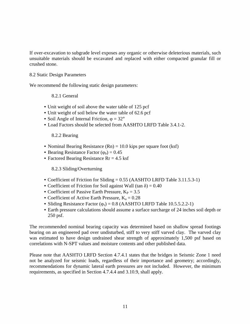
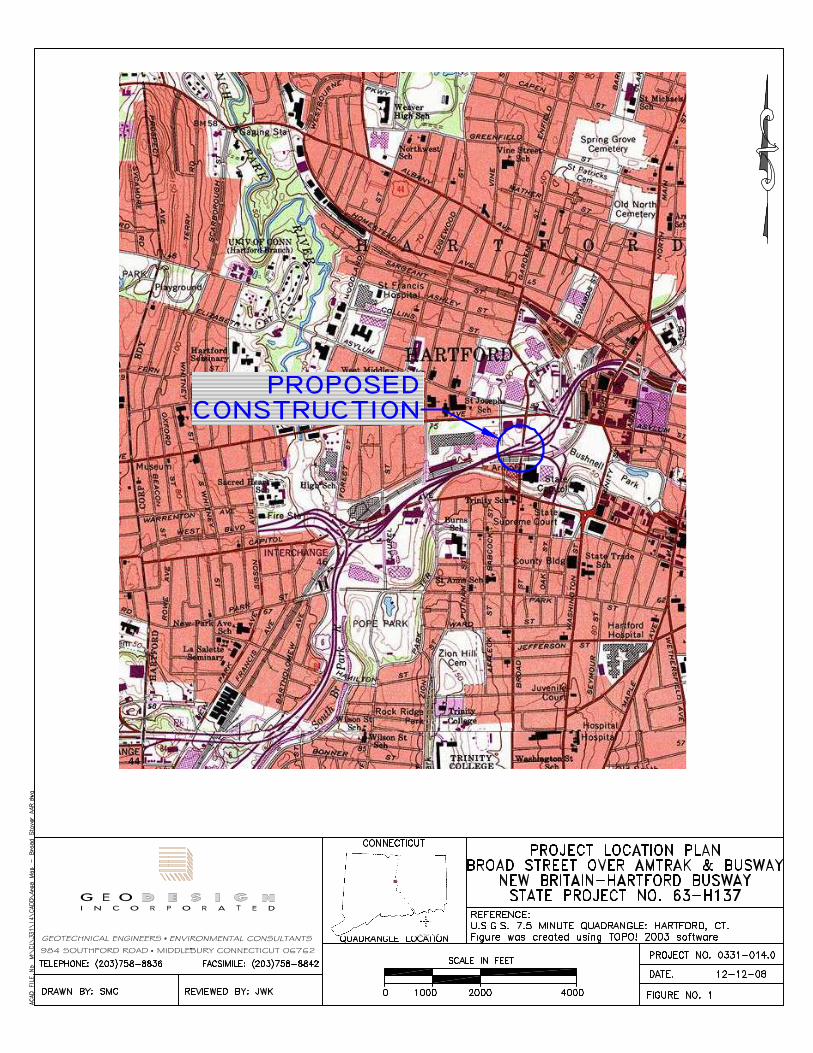
This report summarizes the final design subsurface exploration program, inferred subsurface conditions, and geotechnical analyses; and provides geotechnical engineering recommendations for foundation design for a proposed bridge structure for the Hartford North segment of the proposed New Britain-Hartford Busway (Busway), which will carry Broad Street over Amtrak and the Busway in Hartford, Connecticut. The location of the proposed Broad Street Bridge is shown on Figure 1 (Appendix 1). The Busway project entails the design and construction of a 9.4-mile corridor between downtown New Britain and downtown Hartford that follows an abandoned railroad right-of-way. The Busway will be a dedicated roadway that will be reserved for buses as part of the Bus Rapid Transit System (BRT). The Hartford North segment of the Busway begins approximately 725 feet south of the proposed Sigourney Station at Sta. 450+00, and ends at-grade at Asylum Street at Sta. 490+55. The resulting project length along the baseline is approximately 4,055 feet or about 0.77 miles. This segment of the project is bordered to the south by the Hartford South segment. H.W. Lochner is the Prime Designer for this section of the Busway. GeoDesign, Inc. (GeoDesign) is the Geotechnical Subconsultant to H.W. Lochner.
1.2 Datum
All elevations referenced in this report are in feet and are based on NGVD 1929. The coordinates are based on Connecticut Coordinate System, NAD 1983.
1.3 Existing Conditions
Broad Street is presently carried over Amtrak Railroad by a two-span, prestressed concrete, adjacent box-beam bridge (ConnDOT Bridge No. 03629). The existing bridge crosses over the existing Amtrak railroad with a skew of approximately 4.5 degrees; the existing abutments and piers are also at a similar skew. The bridge was reconstructed to its present configuration in 1975 as shown on Connecticut Department of Transportation, Bureau of Highways design drawings titled “Broad Street Over Penn Central Railroad” dated 1973. The existing railroad is non-electrified. Information regarding the exiting bridge was obtained from the 1973 design drawings. The existing south abutment (termed Abutment 1 since it will be reused) is a concrete stub abutment located behind the previous masonry abutment that was left in place during the 1975 reconstruction of the bridge. The previous bridge consisted of two spans. Its pier was removed but the masonry abutments remain. Although, the old south abutment is not used to support the
2
present bridge, it does retain earth in front of the present stub abutment (Abutment 1). The old north abutment is presumed to be buried at a horizontal distance of about 15 feet behind the present concrete abutment, although it may have been partially demolished during construction of the existing abutment. The existing pier (termed Pier 1 since it will be reused) consists of a concrete pier cap supported by rectangular concrete columns. The columns are integral with a 7.5 ft x 3.0 ft concrete railroad crashwall. The existing north abutment is full height at approximately 27 feet with U-type stepped wing walls. The 1973 design drawings indicate that the three existing substructures are all supported by driven HP10x57 steel piles with bottom of pile cap at approximately El. 42 except Abutment 1 and the wingwall pile caps that are at El. 59. The driven piles are battered (1H:6V) at Abutment 1 and Pier 1. At the existing north abutment, some piles are vertical and some are battered. Existing grades along the Amtrak railroad beneath the bridge are at approximately El. 46, and existing grades behind the bridge abutments are at approximately El. 70. The 1973 design drawings indicate that the Broad Street grades were raised approximately 3 to 6 feet during construction of the present bridge. Available historical information indicates that near the bridge there are eight, 4-inch diameter, SNET conduits encased in the west sidewalk; eight, 5-inch diameter electrical conduits that are supported from the east fascia beam under the east sidewalk; and one abandoned 16-inch diameter water main along the east side of Broad Street and beneath the Amtrak railroad. Figure 2 (Appendix 1) depicts existing site conditions.
1.4 Design Criteria
Foundation design recommendations are based on AASHTO Load and Resistance Factor Bridge Design Specifications, 4th Edition, 2007 (AASHTO LRFD) with Interim Specifications through 2008, and Connecticut Department of Transportation Geotechnical Engineering Manual, 2005 Edition. Recommendations are also based on State of Connecticut Department of Transportation (ConnDOT) Standard Specifications for Roads, Bridges, and Incidental Construction, Form 816 (2004). American Society for Testing and Materials (ASTM) publications were followed as the reference standards for all field and laboratory tests applicable.
1.5 Proposed Structure
In the area of Broad Street Bridge, the proposed Busway will parallel Amtrak’s Springfield Line. Replacement of the existing bridge carrying Broad Street over Amtrak is necessary to provide more space for the Busway. The Broad Street Bridge replacement will involve a full structure replacement, reuse of the existing south abutment (Abutment 1), reuse of the existing pier (Pier 1) footing and crashwall, and construction of a new pier (Pier 2) and a new north abutment (Abutment 2). Schematic locations of existing and proposed substructures and foundations are shown on Figure 3.

3
The new bridge will accommodate three lanes of traffic, two sidewalks, and parapets with protective fence. When replaced, the new bridge will span the Hartford Courant access road, one active railroad track, and a siding track. It will also provide room for one future railroad track, and two Busway lanes. The new bridge will be a three-span steel structure spanning approximately 140 feet between the two abutments. The approximate locations of the existing and proposed substructures are shown on Figure 3 (Appendix 1).
2.0 GEOLOGY Published geologic data for this locale indicate that an Alluvial deposit overlies a Glaciolacustrine deposit, the prevalent surficial material in this area, below fill. A Glacial Till underlies the Glaciolacustrine deposit. These unconsolidated materials overlie bedrock of the Portland Arkose formation. These layers were formed in a bottom to top sequence; thus, the shallower a layer the younger its geological age.
2.1 Alluvial Deposit
Alluvial deposits consist of sediments deposited by present day streams. This deposit is a non-continuous layer with a varying thickness. It consists of fine to medium grained Sand/Silt, with some Clay and little Gravel.
2.2 Glaciolacustrine Deposit
When the late Pleistocene ice sheet in New England retreated about fifteen thousand (15,000) years ago, the Glaciolacustrine deposit was formed in Glacial Lake Hitchcock. The Glaciolacustrine deposit in this area is distinctively featured by alternating layers of clay and silt. Each pair of clay and silt layers is called a “varve”, which corresponds to glacial lake deposit of a year: when the glacier melted, melt water streams brought soil particles into Glacial Lake Hitchcock. During the summer, a larger volume of water formed a more turbulent flow. This flow was capable of carrying silt particles (sometimes even larger particles) and settling them on the lake bottom. During the winter, when the volume of melt water decreased and frozen lake surface calmed the water, clay particles were deposited out of suspension. As a result of many years’ deposit, the “varved” structure dominated the Glaciolacustrine deposit in this region. The deposit could contain several hundred or even several thousand varves. The thickness of the varves is variable. Although this deposit contains significant amount of Silt, the literature typically refers to the Glaciolacustrine deposit in this area as Varved Clay. Conforming to tradition, the term “Varved Clay” is used in this report.
2.3 Glacial Till
Glacial Till consists of a heterogeneous mixture of different sized particles. The composition of Till demonstrates a wide range of variation in particle size and distribution. Two extremes of

4
these variations are stony till and clayey till. The former contains more than fifty percent of gravels, pebbles, cobbles and boulders. The latter consists of more than fifty percent of clay size particles.
2.4 Bedrock
The Portland Arkose formation, a sedimentary bedrock unit, is the dominating formation in this locale. Its texture ranges from coarse conglomerate to shale.
3.0 EXISTING GEOTECHNICAL INFORMATION During the preliminary design phase in 2003, Baker Engineering N.Y. (Baker) and their subcontractors drilled one boring and performed soil laboratory testing. In addition, boring data from explorations performed for the design of the 1975 bridge reconstruction are available.
3.1 General
In 2003, Pilot Boring SB-93 was drilled and in 1973 Borings BH-127 through BH-130 were drilled in the general area of the bridge. Boring SB-93 is located off the east side of the bridge at approximately the mid-span and the BH-Series borings were located on the east and west sides of the bridge at each abutment. The approximate locations of the Pilot Boring and the BH-Series borings are shown on Figure 2 (Appendix 2). The log of the Pilot Boring and the BH-Series borings are included in Appendix 3 and 4, respectively.
3.2 Laboratory Test Data
Baker conducted one of each of the following laboratory tests on samples retrieved from boring SB-93: moisture content, Atterberg Limits, and Gradation (Sieve and Hydrometer) Analyses. The results from these tests are presented in Appendix 6. Details of each test and a discussion of the results are provided in Section 5.0.
4.0 SUBSURFACE EXPLORATIONS GeoDesign conducted additional subsurface explorations during final design. Details of these explorations are described in this section:
4.1 Test Borings
GeoDesign coordinated the services of New England Boring Contractors of CT, Inc. (NEBC) to perform Standard Penetration Test (SPT, ASTM D 1586) borings at the proposed bridge site; six structure borings (B-01-1 through B-01-6) were drilled. Boring locations were initially field located by tape measurement and line of sight and then the Connecticut Department of Transportation (ConnDOT) survey crews recorded the locations and elevations of the borings by

5
surveying the as drilled boring locations. As-drilled borings locations are shown on Figure 2 (Appendix 1) and boring logs are included in Appendix 2.
4.2 Observation Well
An observation well was installed in boring B-01-1. The well installation information is shown on the boring log (Appendix 2).
5.0 LABORATORY TESTING GeoDesign assigned laboratory tests to estimate engineering properties of the Varved Clay and Fill Materials to verify field classifications, evaluate soil corrosion potential, and determine material drainage properties. Testing was performed by Test-Con, Inc. of Danbury, Connecticut. Laboratory tests included Atterberg Limits, sulfide content, and pH on soil samples and unconfined compression strength on intact samples of bedrock. The results of these tests are discussed below and are included in Appendix 5. Laboratory testing was also performed by Baker Engineering in 2003 and the results are included in Appendix 6. Due to the stiffness of the varved clay it was not possible to obtain undisturbed piston tube samples of this stratum. Therefore, site specific consolidation and strength testing was not possible. The compressibility and strength of this stratum was estimated from published data and laboratory test results from other nearby projects (i.e. Busway South and Amtrak Access Road).
5.1 Atterberg Limits
In 2003, Baker performed one Atterberg Limit Test on sample S-4 (depth 10.0’ to 11.5’) from Boring SB-93. Three new Atterberg Limit tests were performed on samples taken from recent Borings B-01-1 and B-01-3. Atterberg Limits (ASTM D 4318) provide the Liquid Limit (LL), the Plastic Limit (PL) and the Plasticity Index (PI) of cohesive soil samples. These tests can characterize cohesive soils and provide a reference to compare soil properties at different depths and locations. A description of the samples tested and the test results are presented below, which are within the range expected for the material respective materials.
Sample/Boring Sample Description PL LL PI S-4/SB-93 (Baker Engineering) sandy lean clay with gravel 14 23 9
S-4/B-01-3 varved silty clay 25 26 1 S-9/B-01-1 varved silty clay 33 64 31 S-10/B-01-1 varved silty clay 27 68 41
5.2 Moisture Contents
In 2003, Baker Engineering performed one moisture content test on sample S-7 (depth 19.5’ to 21.0’) from Boring SB-93. Three new moisture content tests were performed on the samples

6
which the above Atterberg Limits were also performed. Moisture content (ASTM D 2216), like Atterberg Limits, provide an easy way to characterize and compare cohesive soils. The sample tested by Baker Engineering was described as brown silt with little fine to coarse sand and little fine to coarse gravel (Glacial Till). The moisture content from the sample was reported as 14.1 percent. This result is within the range expected for the described material. The moisture contents for samples S-4, S-9, and S-10 described above are 27.1, 32.8, and 34.2 respectively. Based on visual classifications, these samples are described as stiff to very stiff varved Silty Clay. These results are within the range expected for the material.
5.3 Gradation Analyses
In 2003, Baker performed one gradation analysis on sample S-4 from Boring SB-93 that indicated the material consists of brown sandy lean clay. The results are included in Appendix 6.
5.4 pH and Sulfides Tests
Three pH tests and three Sulfide tests were performed on samples of the Fill from recent borings. The Sulfide and pH tests were performed on samples S-1, S-2, and S-5 from Borings taken from Borings B-01-3, B-01-6, and B-01-5, respectively.
5.5 Unconfined Rock Compression Tests
Two unconfined compression tests were performed on bedrock rock samples taken from recent Borings B-01-3 and B-01-4. Unconfined Compression Tests (ASTM D 2938) provide an indication of intact rock core strength. The unconfined compression test results indicate the intact bedrock has an unconfined compressive strength between 4,250 psi and 8,170 psi.
6.0 SUBSURFACE CONDITIONS
6.1 Subsurface Profile
A subsurface profile is shown on Figure 3 (Appendix 1). This profile depicts the generalized subsurface conditions based on the existing and recent subsurface exploration data. The legend for the subsurface profile is included as Figure 4. The soil and rock profile can be summarized as follows:
• Asphalt/Concrete - 0 to 1 foot thick; • Fill - 3 to 23 feet thick; • Silty Sand (Alluvium Deposit)- 0 to 11 feet thick; • Varved Clay (Glaciolacustrine Deposit)- 0 to 15 feet thick; • Glacial Till- 10 to 36 feet thick; • Bedrock (Siltstone/Shale).

7
The Fill generally consists of loose to very dense, fine to coarse Sand with varying proportions of Silt, and (where present) fine to coarse Gravel, Asphalt, Ash, Cinders, Brick/Concrete fragments, and Organic Fibers. Ash and/or Cinders were identified in only three borings (B-01-1, B-01-2, and B-01-6) well above the groundwater table and generally made up less than 10 percent (i.e trace) of the sample. Fill was observed in each of the borings, including the historical borings. The Fill is thickly deposited at the abutments and thinly deposited beneath the bridge. The Silty Sand was only observed in Borings B-01-1 and B-01-3 and is not indicated on the historical borings. The Silty Sand generally consists of dense to very dense fine to coarse Sand to Sand and Silt with little Gravel. The Varved Clay layer was only observed in Borings B-01-1 and B-01-3 and is also indicated on the historical borings from 1973 (BH-Series). The Varved Clay (where encountered) generally consists of stiff to very stiff Silty Clay and Clayey Silt partings although one historical boring, BH-127, indicated soft consistency. Glacial Till was encountered in all the borings. The thickness of the Glacial Till varied from approximately 10 to 36 feet. SPT “N” values indicate the density of this layer ranges from dense to very dense. Bedrock was encountered between approximately El. 19 to 22 with the bedrock sloping slightly upward from north to south. Rock cores were taken in Borings B-01-1, B-01-3, B-01-4, B-01-5A, and B-01-6. Rock Quality Designation (RQD) values ranged between 22 and 83 percent indicating poor to good quality that generally improved with depth.
6.2 Geotechnical Design Parameters
Engineering design parameters of the subsurface soils were based, as appropriate, on the boring data, the laboratory test results. However, the consistency of the varved clay (i.e. stiff to very stiff) precluded the collection of undisturbed samples and as such engineering design parameters were also based on published data from other projects. Below is a summary of the engineering design parameters.
Strata Total Unit Weight (pcf)
Friction Angle (degrees)
Undrained Shear Strength (psf)
Recompression Ratio (Cr)
Fill 125 32 - - Silty Sand 120 32 - -
Varved Clay 115 -- 1,500 0.015 Glacial Till 135 34 - -

8
6.3 Groundwater
Stabilized groundwater readings were made in the observation well in Boring B-01-1. They indicate groundwater at approximately El. 54 (approximately 17 feet below the existing ground surface) in the area behind the Abutment 1. During drilling groundwater levels were also observed at approximate El. 44 in the pier area in Borings B-01-3 and B-01-4. Groundwater conditions will vary depending on factors such as temperature, season, precipitation, construction activity and other conditions, which may be different from those at the time of these readings.
7.0 GEOTECHNICAL ISSUES AND EVALUATION
7.1 Reuse of Existing Substructures
The existing Abutment 1 stem, and the footing and crashwall at Pier 1, will be reused for support of the proposed structure. The referenced historical design drawings for the existing bridge indicate that these two substructures are supported on driven HP10x57 pile foundations. Based on estimated pile lengths of the design drawings and estimated depth to bedrock, these piles are believed to have been driven to bedrock. The condition of the existing HP10x57 piles is unknown at this time. We recognize that the presence of Ash and/or Cinders in the wetted zone (i.e. near the groundwater level) have historically shown accelerated rates of deterioration of steel piles driven into the material. Three borings (B-01-1, B-01-2, and B-01-6) indicate the presence of Ash and/or Cinders in the Fill material on the project. The presence of Ash and/or Cinders is occasional and the amount present is minimal based on the available data and was identified above the wetted zone. Accordingly, we do not anticipate significant corrosion of the steel piles due to the presence of these materials. None the less, due to their age, we recommend that the piles supporting the two substructures that are to be reused, be explored. This is discussed further in Section 8.3.8. Since the proposed spans which will be supported on the Abutment 1 and Pier 1 are either the same length or shorter than the existing spans, it is anticipated that superstructure vertical loading will be similar to the present loading. It was determined that the existing foundations could be safely reused during preliminary design.
7.2 Bridge Loads and Dimensions
H.W. Lochner provided the following final, unfactored loads for the proposed Pier 2 and Abutment 2:
• Pier 2 - Dead Load = 2,170 kips (Superstructure = 870 kips, Substructure = 1,300 kips) • Pier 2 - Live Load = 310 kips • Abutment 2 - Dead Load = 2,317 kips (Superstructure = 317 kips, Substructure = 2,000
kips) • Abutment 2 - Live Load = 363 kips
9
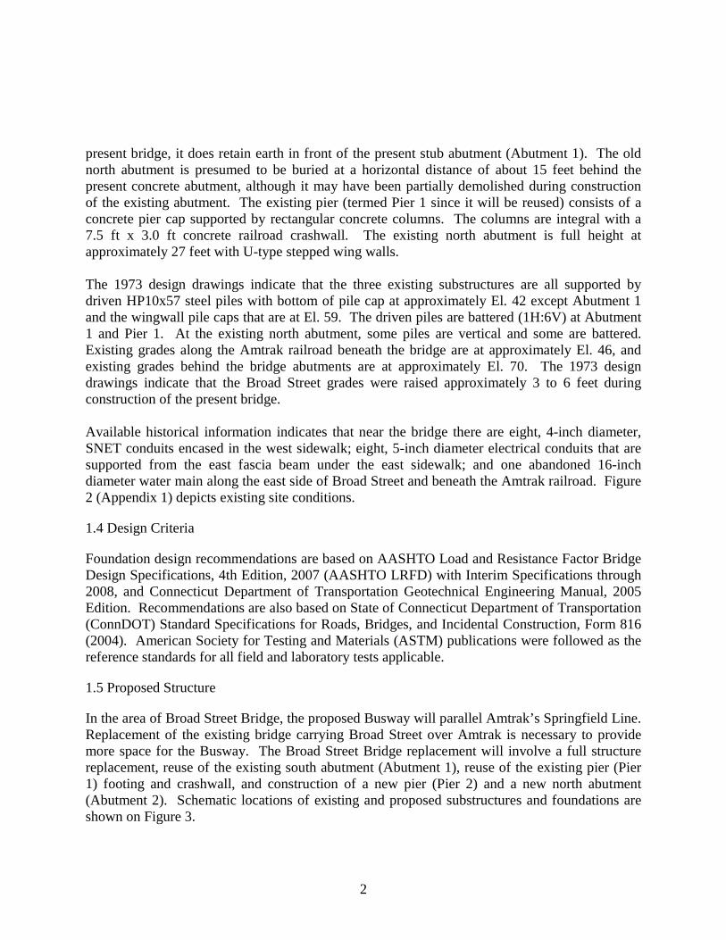
H.W. Lochner also provided final foundation sizes at Pier 2 to be approximately 9.5 ft x 86 ft bearing at El. 38 feet; and at Abutment 2 to be approximately 22.0 ft x 83.8 ft bearing at El. 42 feet. The Pier 2 footing dimension is constrained by the available clearance to the railroad tracks. The location of the Abutment 2 stem is constrained by the Busway. Existing Pier 1 will be fixed and will carry the bridge’s lateral loading.
7.3 Foundation Type Selection
The primary issue that impacts the foundation selection for proposed substructures are: the nominal bearing of subgrade soils, and the settlement of the superstructure under the anticipated loading. Our evaluation of the subsurface conditions and our analysis considering the anticipated bridge loading and dimensions indicates proposed Pier 2 and Abutment 2 can be supported on shallow spread footing foundations. In addition to being more economical and quicker to construct than deep foundations, shallow foundations will be less affected by the presence of existing piles. We therefore recommend that the two new proposed substructures (Pier 2 and Abutment 2) be supported on shallow spread footings. Based on a bottom of footing elevation for Pier 2 at approximately El. 38 ft and approximately El. 42 ft for Abutment 2, we anticipate that proposed shallow spread footing foundations will bear within either the Glacial Till or Varved Clay.
7.4 Settlement Analyses
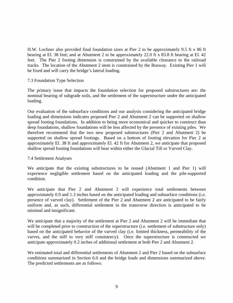
We anticipate that the existing substructures to be reused (Abutment 1 and Pier 1) will experience negligible settlement based on the anticipated loading and the pile-supported condition. We anticipate that Pier 2 and Abutment 2 will experience total settlements between approximately 0.9 and 1.3 inches based on the anticipated loading and subsurface conditions (i.e. presence of varved clay). Settlement of the Pier 2 and Abutment 2 are anticipated to be fairly uniform and, as such, differential settlement in the transverse direction is anticipated to be minimal and insignificant. We anticipate that a majority of the settlement at Pier 2 and Abutment 2 will be immediate that will be completed prior to construction of the superstructure (i.e. settlement of substructure only) based on the anticipated behavior of the varved clay (i.e. limited thickness, permeability of the varves, and the stiff to very stiff consistency). Once the superstructure is constructed we anticipate approximately 0.2 inches of additional settlement at both Pier 2 and Abutment 2. We estimated total and differential settlements of Abutment 2 and Pier 2 based on the subsurface conditions summarized in Section 6.0 and the bridge loads and dimensions summarized above. The predicted settlements are as follows:
10
Substructure Total Predicted Settlement of Substructure
Total Predicted Settlement of Superstructure
Predicted Differential Settlement of Superstructure
Abutment 1 negligible Negligible Pier 1 negligible Negligible Pier 2 0.7 inches 0.2 inches
Abutment 2 1.1 inches 0.2 inches
0.2 inches
These results indicate a maximum of less than about ¼ inch of differential settlement of the superstructure between the pile-supported Pier 1 and the shallow spread footing supported Pier 2. Based on a span length of 56.5 feet between these two substructures, the predicted differential settlement is approximately 1/4000. This angular distortion should be used to estimate negative bending moments in the superstructure.
7.5 Soil Corrosion Potential
As noted in Section 5.4, pH and Sulfide testing on samples collected from the borings were performed. The test results indicate a low potential for corrosion as Sulfides were not detected in any if the samples and the pH levels ranged between 6.90 and 8.62.
7.6 Liquefaction Potential
Soils within and below the bearing zones of the substructures were analyzed with regard to their potential to liquefy during the AASHTO design seismic event for this locale. Based on their relative density and their fines content, the saturated soils are not considered susceptible to liquefaction in the event of a design earthquake. The glacial till and bedrock are also not susceptible to liquefaction.
8.0 GEOTECHNICAL DESIGN AND CONSTRUCTION RECOMMENDATIONS
8.1 General Geotechnical Design Recommendations
We recommend that shallow spread footing foundations bear on a pad of either compacted granular fill or crushed stone over undisturbed natural soils. The thickness of the pad should be at least 18-inches at Pier 2 and 24-inches at Abutment 2. Unless restricted by the temporary lateral support system for railroad protection, the minimum lateral limits of the pad should be at least one foot beyond the edges of the footings and then extending down and away at a slope of 1V:1H to meet the undisturbed subgrade. When using crushed stone, non-woven filter fabric should be placed below the crushed stone. The granular fill should conform to the requirements of Article M.02.02 of FORM 816 and the crushed stone should conform to the requirements of Article M.01.01 (No. 6 Crushed Stone) of Form 816.
11
If over-excavation to subgrade level exposes any organic or otherwise deleterious materials, such unsuitable materials should be excavated and replaced with either compacted granular fill or crushed stone.
8.2 Static Design Parameters
We recommend the following static design parameters:
8.2.1 General
• Unit weight of soil above the water table of 125 pcf • Unit weight of soil below the water table of 62.6 pcf • Soil Angle of Internal Friction, φ = 32°
• Load Factors should be selected from AASHTO LRFD Table 3.4.1-2.
8.2.2 Bearing
• Nominal Bearing Resistance (Rn) = 10.0 kips per square foot (ksf) • Bearing Resistance Factor (φb) = 0.45 • Factored Bearing Resistance Rr = 4.5 ksf
8.2.3 Sliding/Overturning
• Coefficient of Friction for Sliding = 0.55 (AASHTO LRFD Table 3.11.5.3-1) • Coefficient of Friction for Soil against Wall (tan δ) = 0.40
• Coefficient of Passive Earth Pressure, KP = 3.5 • Coefficient of Active Earth Pressure, Ka = 0.28
• Sliding Resistance Factor (φτ) = 0.8 (AASHTO LRFD Table 10.5.5.2.2-1) • Earth pressure calculations should assume a surface surcharge of 24 inches soil depth or
250 psf. The recommended nominal bearing capacity was determined based on shallow spread footings bearing on an engineered pad over undisturbed, stiff to very stiff varved clay. The varved clay was estimated to have design undrained shear strength of approximately 1,500 psf based on correlations with N-SPT values and moisture contents and other published data. Please note that AASHTO LRFD Section 4.7.4.1 states that the bridges in Seismic Zone 1 need not be analyzed for seismic loads, regardless of their importance and geometry; accordingly, recommendations for dynamic lateral earth pressures are not included. However, the minimum requirements, as specified in Section 4.7.4.4 and 3.10.9, shall apply.

12
8.3 Geotechnical Construction Recommendations
8.3.1 Demolition of Existing Foundations
Demolition of the existing north abutment will be required to construct the proposed Pier 2 and Abutment 2. Since the existing north abutment is reportedly supported on driven piles and the proposed structures are to be supported by shallow spread footing foundations, we recommend that existing driven piles beneath proposed shallow spread footing foundations be cut off at least three feet below final subgrade level and the area backfilled with compacted granular fill to subgrade levels.
8.3.2 Subgrade Preparation
Subgrade preparation for shallow spread footings should be conducted in such a way as to minimize disturbance. The final six inches of excavation should be performed with a smooth-edged bucket or a clip attached to the bucket of the excavator or, alternatively, hand-shoveling of the loose, disturbed material such that the subgrade remains essentially undisturbed. Construction operations should be planned to mitigate disturbance to the final subgrade. Disturbed subgrades should be over-excavated to firm stable ground and replaced by compacted granular fill or crushed stone wrapped in a non-woven filter fabric.
8.3.3 Protection of Existing Active Railroad
Excavations to construct shallow spread footing foundations and the engineered pads at Pier 2 and Abutment 2 (to approximate El. 36.5 and El. 40.0, respectively) will entail cuts of approximately six to 10 feet below existing grades. Excavations at Pier 2 will encroach on the protected zone adjacent to live railroad tracks. Specifically, Amtrak requires protection of the existing tracks when construction occurs within two well defined zones. Temporary sheeting is required if excavations extend into “Zone 2” below the boundary defined as a 1V:1.5H downward slope beginning 10 feet outside the centerline of the nearest railroad tracks. Temporary sheeting to be left-in-place is required if excavations extend into “Zone 3” below the boundary defined as a 1V:1H downward slope beginning at the closest end of the railroad tie. It is our opinion the excavation of Pier 2 will extend into “Zone 3” which requires permanent sheeting. Abutment 2 will be at least 10 feet from “Zone 2” at all points; therefore excavations for Abutment 2 will not impact Amtrak. Excavations for Pier 2 and Abutment 2 will require temporary lateral support as discussed above. Based on soil and groundwater conditions, and depth to bedrock, we recommend that braced continuous steel sheet piling be used to provide the support of excavation (SOE) protection. The bracing will require inclined tie-backs with rock anchors. We recommend the following design parameters for temporary lateral earth support at Broad Street:
13
Existing Fill/Silty Sand Total Unit Weight = 125 pounds per cubic foot (pcf) Submerged Unit Weight = 63 pcf Phi = 32 degrees Ka = 0.31 Kp = 3.25
Varved Clay Total Unit Weight = 115 pcf Submerged Unit Weight = 53 pcf Su (Undrained Shear Strength) = 1500 psf
Glacial Till Total Unit Weight = 135 pcf Submerged Unit Weight = 73 pcf Phi = 34 degrees Ka = 0.28 Kp = 3.54
A live load surcharge based on the AREMA Cooper E80 railroad load should also be considered in the design of the temporary lateral support system for railroad protection. We recommend a live load surcharge equivalent to at least 5.5 feet of soil, or about 690 psf, based on a total soil unit weight of 125 pcf. Appropriate contractor coordination with Amtrak will also need to be specified in the contract documents. As the design progresses, we will also provide additional recommendations for the design of the support of excavation and related track monitoring.
8.3.4 Abutment Backfill Requirements
Abutments and wing walls should be designed to comply with ConnDOT Manual Standard, Plate Number 3.5.2 – U-Type wing wall or wall drainage and backfill requirements.
8.3.5 Vibrations and Construction-Induced Settlements
The subsurface conditions encountered do not indicate the presence of loose sandy soils that would be particularly susceptible to settlement induced by vibrations from construction activities. In addition, we are not aware of any existing structures that would be sensitive to vibrations from anticipated construction activities. However, the existing railroad tracks should be monitored in accordance with Amtrak requirements.
14
8.3.6 Abandonment of Existing Utilities
We understand the 16-inch diameter cast iron water line beneath the existing bridge is not in service and has been abandoned. We are not aware of the methods, if any, that were used to abandon this utility. Since shallow spread footing foundations for the proposed bridge may be at or above the elevation of the existing water line, we recommend that the water line be removed in its entirety within 20 feet of Abutment 2 and Pier 2 and replaced with compacted granular fill. In other areas, we recommend the ends of the pipe be located and the pipe filled with grout.
8.3.7 Dewatering
Groundwater may be encountered during foundation installation. Therefore, contractors should be prepared to use sump pumps to control groundwater as needed. Contractors should take extra precaution to dewater in areas where bottom of foundations are close to the Varved Clay. A layer of crushed stone placed on top of the Varved Clay before dewatering is recommended to reduce disturbance to this stratum if it is reached during excavations. If the Varved Clay stratum is disturbed, the disturbed portions must be removed and replaced by crushed stone.
8.3.8 Re-Use of Existing Substructures and Foundations
As previously noted, during preliminary design Baker Engineering and ConnDOT decided to reuse the existing substructures at Abutment 1 and Pier 1. However, we note that the existing condition of the almost 25 year old piles which support these substructures is not known. In particular, the condition of the piles below Abutment 1, which were driven through the Fill may be of concern. To mitigate this possible concern, we recommend that, as a minimum during construction, test pit explorations be performed to evaluate the condition of selected existing Abutment 1 piles which are intended for re-use. These test pits should be relatively easy to excavate in front of (north of) the abutment during the partial demolition of the stub abutment required to construct new bearings and increase clearance below the new span. A review of the load capacity determined by the LRFD method should also be made based on the pile conditions. Based on the results of these explorations and evaluations, existing foundations can be modified as necessary for safe support of the new superstructure.
8.3.9 Special Provisions
Special provisions will be required to address vibration monitoring during sheet piling installation, track settlement monitoring, and exploration and evaluation of selected existing Abutment 1 piles.
9.0 LIMITATIONS This report is subject to the limitations attached in Appendix 7.

Appendix 1 Figures


Drawn By: DSF
ELE
VA
TIO
N (
feet
)
SUBSURFACE PROFILE A-A'
Figure No.: 3
GeoTechnical Engineers and Environmental Consultants984 Southford Road
Middlebury, Connecticut 06762Telephone: 203-758-8836 Fax: 203-758-8842
GE
O S
TA
ND
AR
D 1
1 X
17
(2/1
9/04
) B
OR
ING
LO
GS
200
8.G
PJ
FB
NW
NL0
1.G
DT
12/
16/0
8
0 20
File No.: 0331-014.0
STATION
Broad Street Bridge over Amtrak & BuswayNew Britain - Hartford Busway
State Project No. 63-H137
Notes:1. Data concerning the various strata have been interpreted at boring locations only. The stratigraphy between
borings may vary from that shown.2. Refer to plan view for subsurface profile location. For strata details and symbol legend see Figure 7,
Subsurface Profile Legend, and boring logs appended to this report.3. Numbers displayed beside boring(s) represent SPT "N" values corresponding to their respective sampling
interval. Where coring was performed, numbers represent Recovery and RQD values.4. Structure locations and ground surface profile approximate. Refer to 1973 design drawings for details
regarding existing substructures.
27+00 27+50 28+50 29+00 29+5028+00
A'A South North
Scale (feet)
20
0
20
40
100
80
60
-20 -20
100
80
60
40
0
Reviewed By: JWKDate: 2/18/09
EXISTING BROAD STREETAT APPROXIMATELY EL. 68 FT.
EXISTING BROAD STREETAT APPROXIMATELY EL. 71 FT.
CCEXISTING (REUSED)ABUTMENT 1
GROUND SURFACEAT EL. 46'±
PROPOSEDABUTMENT 2
L EXISTING(REUSED) PIER 1
L PROPOSEDPIER 2
EXISTINGHP10X57
PILES
EXISTING HP10X57PILES
EXISTINGABUTMENT 2
(TO BE DEMOLISHED)
EXISTINGWINGWALL
EXISTING 16" CIWATER (ABANDONED)
64
66
58
90
87
68
90/4"
100/3"
16
66
927
93
145
44
53
74
76
239
1320
1917
71
59
119
100/5"
15
28
41
100
40
2017
30
3117
2650/ 5"
6050/ 4"
1745
4956
101
70/5"
70/5"
7201912
735
62
42
18
17
19
52
60
B-01-4
B-01-1B-01-2
B-01-3
B-01-5 B-01-6B-01-5A
LACTIVETRACK
LSIDINGTRACK
CC
[REC= 97%; RQD= 63%]
[REC= 95%; RQD= 82%]
[REC= 97%; RQD= 33%]
[REC= 100%; RQD= 75%]
[REC= 97%; RQD= 83%]
[REC= 98%; RQD= 65%] [REC= 85%; RQD= 22%]
[REC= 100%; RQD= 53%]
[REC= 100%; RQD= 47%]
[REC= 98%; RQD= 32%]

WEST
Broad Street Bridge over Amtrak & BuswayNew Britain - Hartford Busway
State Project No. 63-H137
-10
0
10
20
30
40
50
60
70
80
Geotechnical Engineers & Environmental Consultants984 Southford Road
Middlebury, Connecticut 06762Telephone: 203-758-8836 Fax: 203-758-8842 Figure No.: 4
SUBSURFACE PROFILE B-B'
B EAST
Date: 2/17/09
B'
-10
0
10
20
30
40
50
60
70
80
File No.: 0331-014.0
-60-80 806040200-20-40
Drawn By: DSF Reviewed By: JWK
Horizontal Distance (feet)
ELE
VA
TIO
N (
feet
)G
EO
ST
AN
DA
RD
8.5
X 1
1 (2
/19/
04)
BO
RIN
G L
OG
S 2
009.
GP
J G
EO
DS
GN
.GD
T 2
/17/
09
44
53
74
76
239
66
16
B-01-5
68
90/4"
100/3"
B-01-5A
19172013
927
93
145
64
66
58
90
87
B-01-6
EXISTINGHP 10x57
PILES
0 20
Notes:1. Data concerning the various strata have been interpreted at boring locations only.
The stratigraphy between borings may vary from that shown.2. Refer to plan view for subsurface profile location. For strata details and symbol
legend see Figure 7, Subsurface Profile Legend, and boring logs appended to thisreport.
3. Numbers displayed beside boring(s) represent SPT "N" values corresponding totheir respective sampling interval. Where coring was performed, numbersrepresent Recovery and RQD values.
4. Structure locations and ground surface profile approximate.
Scale (feet)
EXISTING BROAD STREET ATAPPROXIMATELY EL. 68 FT.
EXISTING 16" CI WATER (ABANDONED)
EXISTING (REUSED) ABUTMENT 1
[REC= 100%; RQD= 75%]
[REC= 97%; RQD= 33%][REC= 97%; RQD= 63%]
[REC= 95%; RQD= 82%]

-10
0
10
20
30
40
50
60
70
80
-10
0
10
20
30
40
50
60
70
80
WEST EAST
Geotechnical Engineers & Environmental Consultants984 Southford Road
Middlebury, Connecticut 06762Telephone: 203-758-8836 Fax: 203-758-8842 Figure No.: 5
SUBSURFACE PROFILE C-C'
C
Date: 2/17/09
C'
Drawn By: DSF Reviewed By: JWK
Horizontal Distance (feet)
ELE
VA
TIO
N (
feet
)G
EO
ST
AN
DA
RD
8.5
X 1
1 (2
/19/
04)
BO
RIN
G L
OG
S 2
009.
GP
J G
EO
DS
GN
.GD
T 2
/17/
09
File No.: 0331-014.0
B-01-3
100
41
28
15
30
1731
2017
40
71
59
119
100/5"
B-01-4
EXISTING BROAD STREET ATAPPROXIMATELY EL. 68 FT.
EXISTING GROUND SURFACEAT APPROXIMATELY EL. 46 FT.
-60 -40 -20 0 20 40 60 80
0 20
Notes:1. Data concerning the various strata have been interpreted at boring locations only.
The stratigraphy between borings may vary from that shown.2. Refer to plan view for subsurface profile location. For strata details and symbol
legend see Figure 7, Subsurface Profile Legend, and boring logs appended to thisreport.
3. Numbers displayed beside boring(s) represent SPT "N" values corresponding totheir respective sampling interval. Where coring was performed, numbersrepresent Recovery and RQD values.
4. Structure locations and ground surface profile approximate.
Broad Street Bridge over Amtrak & BuswayNew Britain - Hartford Busway
State Project No. 63-H137
Scale (feet)
EXISTINGHP 10x57
PILES
EXISTING 16" CI WATER (ABANDONED)
EXISTING (REUSED) PIER 1
[REC= 100%; RQD= 53%]
[REC= 85%; RQD= 22%] [REC= 98%; RQD= 65%]
[REC= 97%; RQD= 83%]
-10
0
10
20
30
40
50
60
70
80
-10
0
10
20
30
40
50
60
70
80
Geotechnical Engineers & Environmental Consultants984 Southford Road
Middlebury, Connecticut 06762Telephone: 203-758-8836 Fax: 203-758-8842
WEST EAST
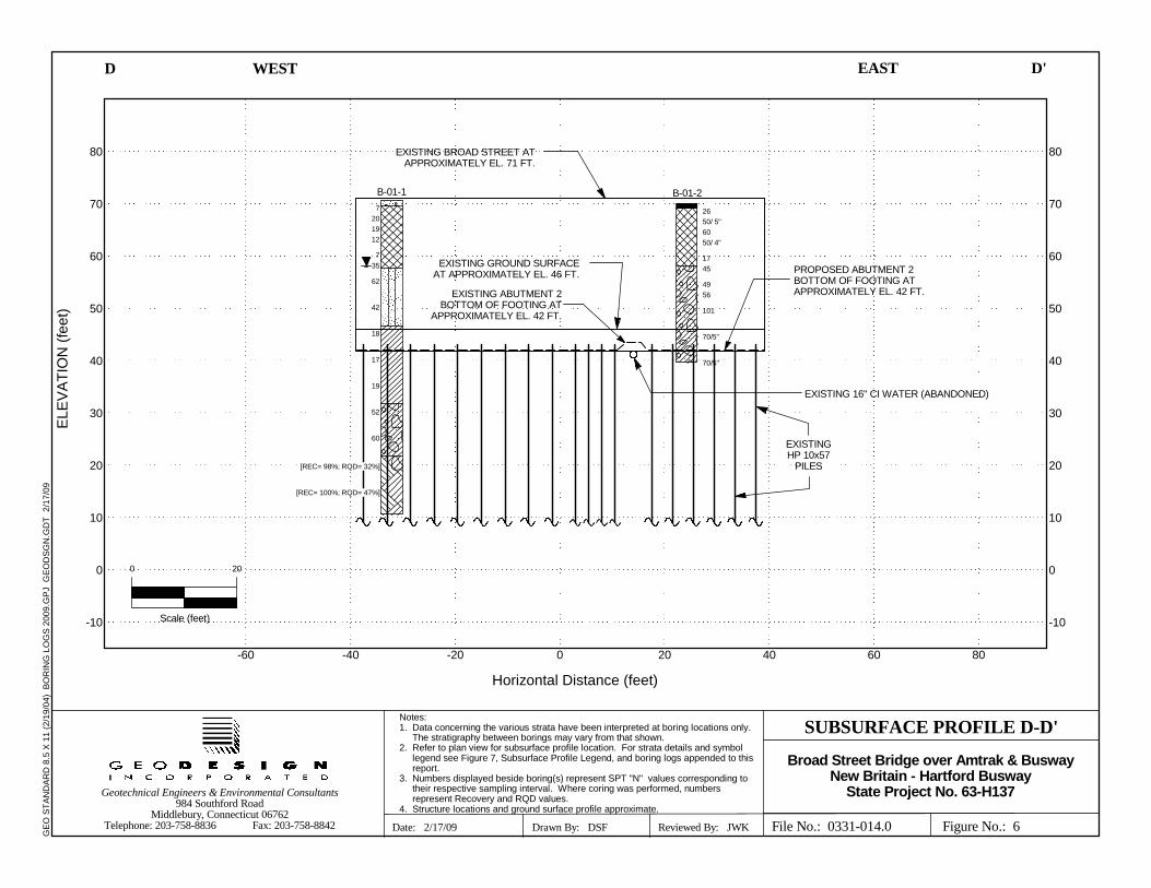
Figure No.: 6
SUBSURFACE PROFILE D-D'
D
Date: 2/17/09
D'
Drawn By: DSF Reviewed By: JWK
Horizontal Distance (feet)
ELE
VA
TIO
N (
feet
)G
EO
ST
AN
DA
RD
8.5
X 1
1 (2
/19/
04)
BO
RIN
G L
OG
S 2
009.
GP
J G
EO
DS
GN
.GD
T 2
/17/
09
File No.: 0331-014.0
B-01-1
7201912
735
62
42
18
17
19
52
60
2650/ 5"6050/ 4"
1745
4956
101
70/5"
70/5"
B-01-2
EXISTING GROUND SURFACEAT APPROXIMATELY EL. 46 FT.
Notes:1. Data concerning the various strata have been interpreted at boring locations only.
The stratigraphy between borings may vary from that shown.2. Refer to plan view for subsurface profile location. For strata details and symbol
legend see Figure 7, Subsurface Profile Legend, and boring logs appended to thisreport.
3. Numbers displayed beside boring(s) represent SPT "N" values corresponding totheir respective sampling interval. Where coring was performed, numbersrepresent Recovery and RQD values.
4. Structure locations and ground surface profile approximate.
0 20
Broad Street Bridge over Amtrak & BuswayNew Britain - Hartford Busway
State Project No. 63-H137
Scale (feet)
EXISTING BROAD STREET ATAPPROXIMATELY EL. 71 FT.
EXISTING ABUTMENT 2BOTTOM OF FOOTING AT
APPROXIMATELY EL. 42 FT.
EXISTING 16" CI WATER (ABANDONED)
EXISTINGHP 10x57
PILES
806040200-20-40-60
PROPOSED ABUTMENT 2BOTTOM OF FOOTING ATAPPROXIMATELY EL. 42 FT.
[REC= 100%; RQD= 47%]
[REC= 98%; RQD= 32%]


Appendix 2 2008 Boring Logs
(B-Series)

Concrete
Fill
Silty Sand
Varved Clay
5" CONCRETE sidewalk
Loose, brown fine to medium SAND, some fine tocoarse Gravel, trace Silt, (dry)
Medium dense, brown fine to medium SAND, littlefine Gravel, trace Silt, trace Cinders, traceCeramic, (moist)
Medium dense, brown fine to medium SAND, littlefine Gravel, trace Roots, (moist)
Medium dense, brown fine to medium SAND, littlefine Gravel, trace Silt, (moist)
Loose, red brown fine SAND and SILT, littleGravel, trace Roots
Top 10": Dense, red brown fine SAND and SILT,little Gravel, trace RootsBottom 6": Dense, red brown fine to mediumSAND and SILT, little Gravel, (wet)
Very dense, red brown fine to coarse SAND andClayey SILT, little fine Gravel, (wet)
Dense, red brown fine to coarse SAND and ClayeySILT, little fine Gravel, (wet)
3 4 3 3
2 10 10 16
9 9 10 7
9 6 6 5
2 3 4 7
7 11 24 25
19 24 38 41
16 18 24 33
24
24
24
24
24
24
24
24
16
12
18
4
18
16
12
12
S-1
S-2
S-3
S-4
S-5
S-6
S-7
S-8
No. ofCore Runs: 2
RQ
D %
Start Date: 10-10-08
Casing Size/Type: 4"/HW
Total Penetration in
Hole No.: B-01-1
Sheet1 of 3
No. ofSoil Samples: 13
Fall: 24"
Sampler Type/Size: SS / 1 3/8"
Groundwater Observations: @12.5 after 0 hours, @16.7', after 336 hours
Gen
eral
ized
Str
ata
Des
crip
tion
Dep
th (
ft)
0
5
10
15
20
25
SAMPLES
Connecticut DOT Boring Report
Material Descriptionand Notes
Blows onSampler
per 6 inches
Core Barrel Type: NQ
Engineer: GeoDesign, Inc.
Rock: 10ft
Sample Type: S = Split Spoon C = Core UP = Undisturbed Piston V = Vane Shear Test
Proportions Used: Trace = 1 - 10%, Little = 10 - 20%, Some = 20 - 35%, And = 35 - 50%
Easting: 1017302.2Surface Elevation: 70.7
SM-001-M REV. 1/02
Pen
. (in
.)
Rec
. (in
.)
Ele
vatio
n (f
t)
70
65
60
55
50
Earth: 50ft
Stat./Offset:
Project Description: New Britain / Hartford Busway -
Sam
ple
Typ
e/N
o.
Town: Hartford
Project No.: 63-H137 / 0331-014.0
Finish Date: 10-10-08 Bridge No.:
Route No.:
Inspector: Garry Jacobson
NOTES: Installed 2" PVC monitoring well to 20' with 10' screen and 10' foot riser.Backfilled with filter sand to 9', bentonite to 7' and drill cuttings to surface. Flush mountprotective box installed at surface.Used solid stem auger to 5', drove casing to 30', open hole 30' to 60'.
Fall: 30"Hammer Wt.: 300 lbs. Hammer Wt.: 140 lbs.
Northing: 839831.2
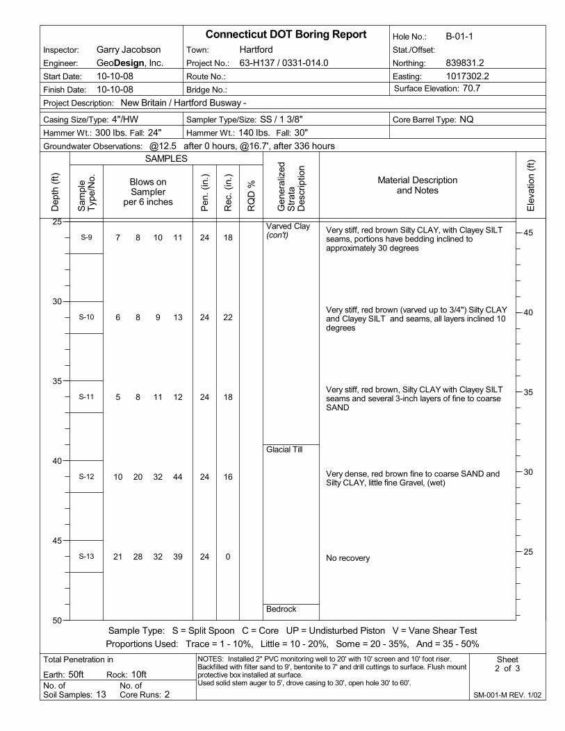
Varved Clay(con't)
Glacial Till
Bedrock
Very stiff, red brown Silty CLAY, with Clayey SILTseams, portions have bedding inclined toapproximately 30 degrees
Very stiff, red brown (varved up to 3/4") Silty CLAYand Clayey SILT and seams, all layers inclined 10degrees
Very stiff, red brown, Silty CLAY with Clayey SILTseams and several 3-inch layers of fine to coarseSAND
Very dense, red brown fine to coarse SAND andSilty CLAY, little fine Gravel, (wet)
No recovery
7 8 10 11
6 8 9 13
5 8 11 12
10 20 32 44
21 28 32 39
24
24
24
24
24
18
22
18
16
0
S-9
S-10
S-11
S-12
S-13
No. ofCore Runs: 2
RQ
D %
Start Date: 10-10-08
Casing Size/Type: 4"/HW
Total Penetration in
Hole No.: B-01-1
Sheet2 of 3
No. ofSoil Samples: 13
Fall: 24"
Sampler Type/Size: SS / 1 3/8"
Groundwater Observations: @12.5 after 0 hours, @16.7', after 336 hours
Gen
eral
ized
Str
ata
Des
crip
tion
Dep
th (
ft)
25
30
35
40
45
50
SAMPLES
Connecticut DOT Boring Report
Material Descriptionand Notes
Blows onSampler
per 6 inches
Core Barrel Type: NQ
Engineer: GeoDesign, Inc.
Rock: 10ft
Sample Type: S = Split Spoon C = Core UP = Undisturbed Piston V = Vane Shear Test
Proportions Used: Trace = 1 - 10%, Little = 10 - 20%, Some = 20 - 35%, And = 35 - 50%
Easting: 1017302.2Surface Elevation: 70.7
SM-001-M REV. 1/02
Pen
. (in
.)
Rec
. (in
.)
Ele
vatio
n (f
t)
45
40
35
30
25
Earth: 50ft
Stat./Offset:
Project Description: New Britain / Hartford Busway -
Sam
ple
Typ
e/N
o.
Town: Hartford
Project No.: 63-H137 / 0331-014.0
Finish Date: 10-10-08 Bridge No.:
Route No.:
Inspector: Garry Jacobson
NOTES: Installed 2" PVC monitoring well to 20' with 10' screen and 10' foot riser.Backfilled with filter sand to 9', bentonite to 7' and drill cuttings to surface. Flush mountprotective box installed at surface.Used solid stem auger to 5', drove casing to 30', open hole 30' to 60'.
Fall: 30"Hammer Wt.: 300 lbs. Hammer Wt.: 140 lbs.
Northing: 839831.2

32
47
Bedrock(con't)
Poor, Moderately Hard, Slightly Weathered, gray(turns red brown @ 5'), aphanitic SILTSTONEPrimary joints (bedding plane) are low angle 1" to6" spacing. Several vertical, curved, irregular joints,extremely weathered zone from 53.8 to 54.2Coring time (min./ ft.): 8, 8, 8, 8, 7
Poor, Moderately Hard, Slightly Weathered, red,aphanitic SILTSTONEPrimary joints (bedding plane) are low angle 1" to6" spacing. Several vertical, curved, irregular joints,very thin bedding is evidentCoring time (min./ ft.): 8, 8, 8, 9, 9
END OF BORING 60ft
60
60
59
60
C-1
C-2
No. ofCore Runs: 2
RQ
D %
Start Date: 10-10-08
Casing Size/Type: 4"/HW
Total Penetration in
Hole No.: B-01-1
Sheet3 of 3
No. ofSoil Samples: 13
Fall: 24"
Sampler Type/Size: SS / 1 3/8"
Groundwater Observations: @12.5 after 0 hours, @16.7', after 336 hours
Gen
eral
ized
Str
ata
Des
crip
tion
Dep
th (
ft)
50
55
60
65
70
75
SAMPLES
Connecticut DOT Boring Report
Material Descriptionand Notes
Blows onSampler
per 6 inches
Core Barrel Type: NQ
Engineer: GeoDesign, Inc.
Rock: 10ft
Sample Type: S = Split Spoon C = Core UP = Undisturbed Piston V = Vane Shear Test
Proportions Used: Trace = 1 - 10%, Little = 10 - 20%, Some = 20 - 35%, And = 35 - 50%
Easting: 1017302.2Surface Elevation: 70.7
SM-001-M REV. 1/02
Pen
. (in
.)
Rec
. (in
.)
Ele
vatio
n (f
t)
20
15
10
5
0
Earth: 50ft
Stat./Offset:
Project Description: New Britain / Hartford Busway -
Sam
ple
Typ
e/N
o.
Town: Hartford
Project No.: 63-H137 / 0331-014.0
Finish Date: 10-10-08 Bridge No.:
Route No.:
Inspector: Garry Jacobson
NOTES: Installed 2" PVC monitoring well to 20' with 10' screen and 10' foot riser.Backfilled with filter sand to 9', bentonite to 7' and drill cuttings to surface. Flush mountprotective box installed at surface.Used solid stem auger to 5', drove casing to 30', open hole 30' to 60'.
Fall: 30"Hammer Wt.: 300 lbs. Hammer Wt.: 140 lbs.
Northing: 839831.2

Pavement
Fill
Glacial Till
3" ASPHALT over 9" CONCRETE
Medium dense, red brown fine to medium SAND,some Silt, little fine to coarse Gravel, trace Ash/CindersVery dense, brown fine to medium SAND, someSilt, little fine to coarse Gravel, trace Concretefragments, trace Organics
Very dense, brown fine to medium SAND, somefine to coarse Gravel, little Silt, trace Ash/Cinders/Concrete fragmentsVery dense, brown fine to medium SAND, somefine to coarse Gravel, little Silt, traceAsh/Cinders/Concrete fragments
Medium dense, brown fine to coarse GRAVEL,trace fine to coarse Sand
No recovery
No recovery
Very dense, red brown fine to medium SAND,some Clayey Silt, little fine to coarse Gravel, (wet)
Very dense, red brown fine to medium SAND,some Silt, little fine Gravel, (wet)
12 11 15 26
31 50/ 5"
26 35 25 38
50/ 4"
4 5 12 18
19 22 23 24
39 25 24 35
18 25 31 70/4"
24 44 57 67
24
11
24
4
24
24
24
22
24
6
8
12
3
2
0
0
12
12
S-1
S-2
S-3
S-4
S-5
S-6
S-7
S-8
S-9
No. ofCore Runs: 0
RQ
D %
Start Date: 10-9-08
Casing Size/Type: 3"/NW
Total Penetration in
Hole No.: B-01-2
Sheet1 of 2
No. ofSoil Samples: 11
Fall: 24"
Sampler Type/Size: SS / 1 3/8"
Groundwater Observations: @15.5' after 0.0 hours
Gen
eral
ized
Str
ata
Des
crip
tion
Dep
th (
ft)
0
5
10
15
20
25
SAMPLES
Connecticut DOT Boring Report
Material Descriptionand Notes
Blows onSampler
per 6 inches
Core Barrel Type: NQ
Engineer: GeoDesign, Inc.
Rock: 0ft
Sample Type: S = Split Spoon C = Core UP = Undisturbed Piston V = Vane Shear Test
Proportions Used: Trace = 1 - 10%, Little = 10 - 20%, Some = 20 - 35%, And = 35 - 50%
Easting: 1017358.5Surface Elevation: 70.1
SM-001-M REV. 1/02
Pen
. (in
.)
Rec
. (in
.)
Ele
vatio
n (f
t)
70
65
60
55
50
Earth: 30.4ft
Stat./Offset:
Project Description: New Britain / Hartford Busway -
Sam
ple
Typ
e/N
o.
Town: Hartford
Project No.: 63-H137 / 0331-014.0
Finish Date: 10-9-08 Bridge No.:
Route No.:
Inspector: Robert Marshall
NOTES:
Fall: 30"Hammer Wt.: 300 lbs. Hammer Wt.: 140 lbs.
Northing: 839828.6

Glacial Till(con't)
Very dense, red brown fine to medium SAND,some Silt, little fine Gravel, (wet)
Very dense, red brown coarse GRAVEL, somefine to medium Sand, little Silt, (wet)
END OF BORING 30.4ft
38 57 70/5"
70/5"
17
5
14
2
S-10
S-11
No. ofCore Runs: 0
RQ
D %
Start Date: 10-9-08
Casing Size/Type: 3"/NW
Total Penetration in
Hole No.: B-01-2
Sheet2 of 2
No. ofSoil Samples: 11
Fall: 24"
Sampler Type/Size: SS / 1 3/8"
Groundwater Observations: @15.5' after 0.0 hours
Gen
eral
ized
Str
ata
Des
crip
tion
Dep
th (
ft)
25
30
35
40
45
50
SAMPLES
Connecticut DOT Boring Report
Material Descriptionand Notes
Blows onSampler
per 6 inches
Core Barrel Type: NQ
Engineer: GeoDesign, Inc.
Rock: 0ft
Sample Type: S = Split Spoon C = Core UP = Undisturbed Piston V = Vane Shear Test
Proportions Used: Trace = 1 - 10%, Little = 10 - 20%, Some = 20 - 35%, And = 35 - 50%
Easting: 1017358.5Surface Elevation: 70.1
SM-001-M REV. 1/02
Pen
. (in
.)
Rec
. (in
.)
Ele
vatio
n (f
t)
45
40
35
30
25
Earth: 30.4ft
Stat./Offset:
Project Description: New Britain / Hartford Busway -
Sam
ple
Typ
e/N
o.
Town: Hartford
Project No.: 63-H137 / 0331-014.0
Finish Date: 10-9-08 Bridge No.:
Route No.:
Inspector: Robert Marshall
NOTES:
Fall: 30"Hammer Wt.: 300 lbs. Hammer Wt.: 140 lbs.
Northing: 839828.6

Fill
Silty Sand
Varved Clay
Glacial Till
Top 8": Medium dense, black fine to coarseSAND and GRAVEL, little SiltBottom 7": Medium dense, brown fine to mediumSAND, trace Gravel, trace SiltTop 9": Dense, brown fine to medium SAND,trace Gravel, trace SiltBottom 4": Dense, dark red brown Clayey SILT,some fine to coarse Sand, little Gravel, (wet)
Top 4": Dense, dark red brown Clayey SILT, somefine to coarse Sand, little Gravel, (wet)Bottom 10": Dense, brown SILT, (wet)
Stiff, (varved 1" thick) red brown to tan varvedCLAY
Medium dense, red brown Clayey SILT, some fineto coarse Sand, little fine Gravel, (wet)
Dense, red brown Clayey SILT, some fine tocoarse Sand, little fine to coarse Gravel, (wet)
14 8 9 10
10 13 18 19
15 13 17 15
6 7 8 12
8 10 18 26
11 17 24 25
24
24
24
24
24
24
15
13
14
16
22
14
S-1
S-2
S-3
S-4
S-5
S-6
No. ofCore Runs: 2
RQ
D %
Start Date: 9-25-08
Casing Size/Type: 4"/HW
Total Penetration in
Hole No.: B-01-3
Sheet1 of 2
No. ofSoil Samples: 7
Fall: 24"
Sampler Type/Size: SS / 1 3/8"
Groundwater Observations: @2.5 ' after 0 hrs.
Gen
eral
ized
Str
ata
Des
crip
tion
Dep
th (
ft)
0
5
10
15
20
25
SAMPLES
Connecticut DOT Boring Report
Material Descriptionand Notes
Blows onSampler
per 6 inches
Core Barrel Type: NQ
Engineer: GeoDesign, Inc.
Rock: 10ft
Sample Type: S = Split Spoon C = Core UP = Undisturbed Piston V = Vane Shear Test
Proportions Used: Trace = 1 - 10%, Little = 10 - 20%, Some = 20 - 35%, And = 35 - 50%
Easting: 1017288.2Surface Elevation: 46.7
SM-001-M REV. 1/02
Pen
. (in
.)
Rec
. (in
.)
Ele
vatio
n (f
t)
45
40
35
30
25
Earth: 30ft
Stat./Offset:
Project Description: New Britain / Hartford Busway -
Sam
ple
Typ
e/N
o.
Town: Hartford
Project No.: 63-H137 / 0331-014.0
Finish Date: 9-29-08 Bridge No.:
Route No.:
Inspector: Garry Jacobson
NOTES:
Fall: 30"Hammer Wt.: 300 lbs. Hammer Wt.: 140 lbs.
Northing: 839734.7
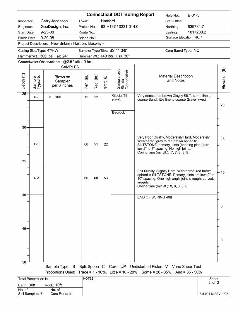
22
53
Glacial Till(con't)
Bedrock
Very dense, red brown Clayey SILT, some fine tocoarse Sand, little fine to coarse Gravel, (wet)
Very Poor Quality, Moderately Hard, ModeratelyWeathered, gray to red brown aphaniticSILTSTONE, primary joints (bedding plane) arelow 2" to 8" spacing. No high joints.Coring time (min./ft.): 7, 7, 8, 8, 8
Fair Quality, Slightly Hard, Weathered, red brownaphanitic SILTSTONE. Primary joints are low, 2" to10" spacing. One high angle joint is rough, curved,irregular.Coring time (min./ft.): 8, 8, 8, 8, 8
END OF BORING 40ft
31 100 12
60
60
12
51
60
S-7
C-1
C-2
No. ofCore Runs: 2
RQ
D %
Start Date: 9-25-08
Casing Size/Type: 4"/HW
Total Penetration in
Hole No.: B-01-3
Sheet2 of 2
No. ofSoil Samples: 7
Fall: 24"
Sampler Type/Size: SS / 1 3/8"
Groundwater Observations: @2.5 ' after 0 hrs.
Gen
eral
ized
Str
ata
Des
crip
tion
Dep
th (
ft)
25
30
35
40
45
50
SAMPLES
Connecticut DOT Boring Report
Material Descriptionand Notes
Blows onSampler
per 6 inches
Core Barrel Type: NQ
Engineer: GeoDesign, Inc.
Rock: 10ft
Sample Type: S = Split Spoon C = Core UP = Undisturbed Piston V = Vane Shear Test
Proportions Used: Trace = 1 - 10%, Little = 10 - 20%, Some = 20 - 35%, And = 35 - 50%
Easting: 1017288.2Surface Elevation: 46.7
SM-001-M REV. 1/02
Pen
. (in
.)
Rec
. (in
.)
Ele
vatio
n (f
t)
20
15
10
5
0
Earth: 30ft
Stat./Offset:
Project Description: New Britain / Hartford Busway -
Sam
ple
Typ
e/N
o.
Town: Hartford
Project No.: 63-H137 / 0331-014.0
Finish Date: 9-29-08 Bridge No.:
Route No.:
Inspector: Garry Jacobson
NOTES:
Fall: 30"Hammer Wt.: 300 lbs. Hammer Wt.: 140 lbs.
Northing: 839734.7

CrushedStoneFill
Glacial Till
Top 8": Medium dense, gray fine to coarseGRAVELBottom 7": Medium dense, gray fine to coarseSAND and SILT, (moist)Top 12": Medium dense, brown fine to coarseSAND, trace Silt, (wet)Bottom 7": Medium dense, red brown Clayey SILT,some fine to coarse Sand, (wet)
Dense, red brown Clayey SILT, some fine tocoarse Sand, little fine to coarse Gravel, (wet)
Very dense, red brown Clayey SILT, some fine tocoarse Sand, little fine to coarse Gravel, (wet)
Very dense, red brown Clayey SILT, some fine tocoarse Sand, little fine to coarse Gravel, (wet)
Very dense, red brown Clayey SILT, some fine tocoarse Sand, little fine to coarse Gravel, (wet)
6 11 9 10
3 9 8 8
13 15 25 35
21 33 38 44
16 24 35 38
14 19 100
24
24
24
24
24
18
15
19
18
20
14
10
S-1
S-2
S-3
S-4
S-5
S-6
No. ofCore Runs: 2
RQ
D %
Start Date: 9-25-08
Casing Size/Type: 4"/HW
Total Penetration in
Hole No.: B-01-4
Sheet1 of 2
No. ofSoil Samples: 7
Fall: 24"
Sampler Type/Size: SS / 1 3/8"
Groundwater Observations: @3' during drilling
Gen
eral
ized
Str
ata
Des
crip
tion
Dep
th (
ft)
0
5
10
15
20
25
SAMPLES
Connecticut DOT Boring Report
Material Descriptionand Notes
Blows onSampler
per 6 inches
Core Barrel Type: NQ
Engineer: GeoDesign, Inc.
Rock: 10ft
Sample Type: S = Split Spoon C = Core UP = Undisturbed Piston V = Vane Shear Test
Proportions Used: Trace = 1 - 10%, Little = 10 - 20%, Some = 20 - 35%, And = 35 - 50%
Easting: 1017360.9Surface Elevation: 46.8
SM-001-M REV. 1/02
Pen
. (in
.)
Rec
. (in
.)
Ele
vatio
n (f
t)
45
40
35
30
25
Earth: 30ft
Stat./Offset:
Project Description: New Britain / Hartford Busway -
Sam
ple
Typ
e/N
o.
Town: Hartford
Project No.: 63-H137 / 0331-014.0
Finish Date: 9-25-08 Bridge No.:
Route No.:
Inspector: Garry Jacobson
NOTES: Used solid stem augers to 10'. Drove casing to 20', then open hole.
Fall: 30"Hammer Wt.: 300 lbs. Hammer Wt.: 140 lbs.
Northing: 839728.0

65
83
Glacial Till(con't)
Bedrock
Very dense, red brown Clayey SILT, some fine tocoarse Sand, little fine to coarse Gravel, (wet)
Fair, Moderately Hard, Slightly Weathered, gray,aphanitic SILTSTONE. Bedding is massive.Primary joints horizontal, 2" to 18" spacing.Several high angle secondary joints are rough,carved.Coring time (min./ ft.): 7, 7, 7, 8, 8
Fair, Moderately Hard, Slightly Weathered, gray,aphanitic SILTSTONE. Bedding is massive.Primary joint spacing is 2" to 24" and nosecondary joints.Coring time (min./ ft.): 8, 8, 8, 9, 9
END OF BORING 40ft
100/5" 5
60
60
4
59
58
S-7
C-1
C-2
No. ofCore Runs: 2
RQ
D %
Start Date: 9-25-08
Casing Size/Type: 4"/HW
Total Penetration in
Hole No.: B-01-4
Sheet2 of 2
No. ofSoil Samples: 7
Fall: 24"
Sampler Type/Size: SS / 1 3/8"
Groundwater Observations: @3' during drilling
Gen
eral
ized
Str
ata
Des
crip
tion
Dep
th (
ft)
25
30
35
40
45
50
SAMPLES
Connecticut DOT Boring Report
Material Descriptionand Notes
Blows onSampler
per 6 inches
Core Barrel Type: NQ
Engineer: GeoDesign, Inc.
Rock: 10ft
Sample Type: S = Split Spoon C = Core UP = Undisturbed Piston V = Vane Shear Test
Proportions Used: Trace = 1 - 10%, Little = 10 - 20%, Some = 20 - 35%, And = 35 - 50%
Easting: 1017360.9Surface Elevation: 46.8
SM-001-M REV. 1/02
Pen
. (in
.)
Rec
. (in
.)
Ele
vatio
n (f
t)
20
15
10
5
0
Earth: 30ft
Stat./Offset:
Project Description: New Britain / Hartford Busway -
Sam
ple
Typ
e/N
o.
Town: Hartford
Project No.: 63-H137 / 0331-014.0
Finish Date: 9-25-08 Bridge No.:
Route No.:
Inspector: Garry Jacobson
NOTES: Used solid stem augers to 10'. Drove casing to 20', then open hole.
Fall: 30"Hammer Wt.: 300 lbs. Hammer Wt.: 140 lbs.
Northing: 839728.0

Topsoil
Fill
Glacial Till
Loose, brownTop 6": TOPSOILBottom 7": CLAY, fine Sand, little Silt, (moist)
No recovery
Loose, red brown, fine to coarse SAND, little fineGravel, trace Silt
Very loose, red brown, fine to coarse SAND, littlefine Gravel, trace Silt
Loose, red brown, fine to coarse SAND, little fineGravel, trace Silt, (wet)
No recovery
Loose, red brown, fine to coarse SAND, some fineGravel, trace Silt, (wet)
Loose, red brown, fine to coarse SAND, some fineGravel, trace Silt, (wet)
Medium dense, red brown, fine to coarse SAND,little fine Gravel, little Silt
Top 4": Loose, red brown, fine to coarse SAND,little fine Gravel, little SiltBottom 5": Loose, red brown Clayey SILT, somefine to coarse Sand, trace fine Gravel
1 2 2 3
3 2 2 3
6 3 2 4
2 2 1 2
10 4 3 4
3 2 2 3
5 3 4 3
3 2 4 3
13 12 11 10
20 4 5 7
24
24
24
24
24
24
24
24
24
24
13
0
3
1
6
0
2
2
12
9
S-1
S-2
S-3
S-4
S-5
S-6
S-7
S-8
S-9
S-10
No. ofCore Runs: 0
RQ
D %
Start Date: 10-8-08
Casing Size/Type: 4"/HW
Total Penetration in
Hole No.: B-01-5
Sheet1 of 2
No. ofSoil Samples: 12
Fall: 24"
Sampler Type/Size: SS / 1 3/8"
Groundwater Observations: @None observed
Gen
eral
ized
Str
ata
Des
crip
tion
Dep
th (
ft)
0
5
10
15
20
25
SAMPLES
Connecticut DOT Boring Report
Material Descriptionand Notes
Blows onSampler
per 6 inches
Core Barrel Type:
Engineer: GeoDesign, Inc.
Rock: 0ft
Sample Type: S = Split Spoon C = Core UP = Undisturbed Piston V = Vane Shear Test
Proportions Used: Trace = 1 - 10%, Little = 10 - 20%, Some = 20 - 35%, And = 35 - 50%
Easting: 1017277.3Surface Elevation: 67.7
SM-001-M REV. 1/02
Pen
. (in
.)
Rec
. (in
.)
Ele
vatio
n (f
t)
65
60
55
50
45
Earth: 32ft
Stat./Offset:
Project Description: New Britain / Hartford Busway -
Sam
ple
Typ
e/N
o.
Town: Hartford
Project No.: 63-H137 / 0331-014.0
Finish Date: 10-8-08 Bridge No.:
Route No.:
Inspector: Ray Underwood
NOTES: Casing was pushed to 10' and spun when roller bit reached 10'. After takingS-5 pushed casing down to 15'.
Fall: 30"Hammer Wt.: 300 lbs. Hammer Wt.: 140 lbs.
Northing: 839658.4
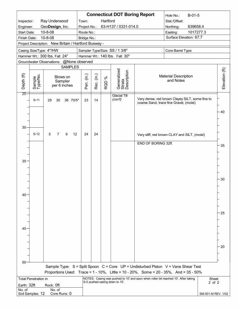
Glacial Till(con't) Very dense, red brown Clayey SILT, some fine to
coarse Sand, trace fine Gravel, (moist)
Very stiff, red brown CLAY and SILT, (moist)
END OF BORING 32ft
29 30 36 70/5"
5 7 9 12
23
24
14
24
S-11
S-12
No. ofCore Runs: 0
RQ
D %
Start Date: 10-8-08
Casing Size/Type: 4"/HW
Total Penetration in
Hole No.: B-01-5
Sheet2 of 2
No. ofSoil Samples: 12
Fall: 24"
Sampler Type/Size: SS / 1 3/8"
Groundwater Observations: @None observed
Gen
eral
ized
Str
ata
Des
crip
tion
Dep
th (
ft)
25
30
35
40
45
50
SAMPLES
Connecticut DOT Boring Report
Material Descriptionand Notes
Blows onSampler
per 6 inches
Core Barrel Type:
Engineer: GeoDesign, Inc.
Rock: 0ft
Sample Type: S = Split Spoon C = Core UP = Undisturbed Piston V = Vane Shear Test
Proportions Used: Trace = 1 - 10%, Little = 10 - 20%, Some = 20 - 35%, And = 35 - 50%
Easting: 1017277.3Surface Elevation: 67.7
SM-001-M REV. 1/02
Pen
. (in
.)
Rec
. (in
.)
Ele
vatio
n (f
t)
40
35
30
25
20
Earth: 32ft
Stat./Offset:
Project Description: New Britain / Hartford Busway -
Sam
ple
Typ
e/N
o.
Town: Hartford
Project No.: 63-H137 / 0331-014.0
Finish Date: 10-8-08 Bridge No.:
Route No.:
Inspector: Ray Underwood
NOTES: Casing was pushed to 10' and spun when roller bit reached 10'. After takingS-5 pushed casing down to 15'.
Fall: 30"Hammer Wt.: 300 lbs. Hammer Wt.: 140 lbs.
Northing: 839658.4

-
Refer to log of boring B-01-5 for strata descriptionabove 35 feet.
No. ofCore Runs: 2
RQ
D %
Start Date: 10-24-08
Casing Size/Type: 4"/HW
Total Penetration in
Hole No.: B-01-5A
Sheet1 of 3
No. ofSoil Samples: 3
Fall: 24"
Sampler Type/Size: SS / 1 3/8"
Groundwater Observations: @None observed
Gen
eral
ized
Str
ata
Des
crip
tion
Dep
th (
ft)
0
5
10
15
20
25
SAMPLES
Connecticut DOT Boring Report
Material Descriptionand Notes
Blows onSampler
per 6 inches
Core Barrel Type: NQ
Engineer: GeoDesign, Inc.
Rock: 10ft
Sample Type: S = Split Spoon C = Core UP = Undisturbed Piston V = Vane Shear Test
Proportions Used: Trace = 1 - 10%, Little = 10 - 20%, Some = 20 - 35%, And = 35 - 50%
Easting: 1017297.3Surface Elevation: 67.5
SM-001-M REV. 1/02
Pen
. (in
.)
Rec
. (in
.)
Ele
vatio
n (f
t)
65
60
55
50
45
Earth: 47ft
Stat./Offset:
Project Description: New Britain / Hartford Busway -
Sam
ple
Typ
e/N
o.
Town: Hartford
Project No.: 63-H137 / 0331-014.0
Finish Date: 10-24-08 Bridge No.:
Route No.:
Inspector: Robert Marshall
NOTES: Pilot hole to 5' with 4" OD SSA, then switched to 4" casing to 30'.Boring advance open hole below 30'.
Fall: 30"Hammer Wt.: 300 lbs. Hammer Wt.: 140 lbs.
Northing: 839658.7

75
-(con't)
Glacial Till
Bedrock
Very dense, red brown Clayey SILT, little fine tomedium Sand, trace fine Gravel
Very dense, red brown Clayey SILT, little fine tomedium Sand, trace fine Gravel
Very dense, red brown SILT and CLAY, little fine tomedium Sand
Good, Moderately Hard, Slightly Weathered, gray,SILTSTONE
14 26 42 49
49 62 90/4"
80 100/3"
24
16
9
60
8
12
7
60
S-1
S-2
S-3
C-1
No. ofCore Runs: 2
RQ
D %
Start Date: 10-24-08
Casing Size/Type: 4"/HW
Total Penetration in
Hole No.: B-01-5A
Sheet2 of 3
No. ofSoil Samples: 3
Fall: 24"
Sampler Type/Size: SS / 1 3/8"
Groundwater Observations: @None observed
Gen
eral
ized
Str
ata
Des
crip
tion
Dep
th (
ft)
25
30
35
40
45
50
SAMPLES
Connecticut DOT Boring Report
Material Descriptionand Notes
Blows onSampler
per 6 inches
Core Barrel Type: NQ
Engineer: GeoDesign, Inc.
Rock: 10ft
Sample Type: S = Split Spoon C = Core UP = Undisturbed Piston V = Vane Shear Test
Proportions Used: Trace = 1 - 10%, Little = 10 - 20%, Some = 20 - 35%, And = 35 - 50%
Easting: 1017297.3Surface Elevation: 67.5
SM-001-M REV. 1/02
Pen
. (in
.)
Rec
. (in
.)
Ele
vatio
n (f
t)
40
35
30
25
20
Earth: 47ft
Stat./Offset:
Project Description: New Britain / Hartford Busway -
Sam
ple
Typ
e/N
o.
Town: Hartford
Project No.: 63-H137 / 0331-014.0
Finish Date: 10-24-08 Bridge No.:
Route No.:
Inspector: Robert Marshall
NOTES: Pilot hole to 5' with 4" OD SSA, then switched to 4" casing to 30'.Boring advance open hole below 30'.
Fall: 30"Hammer Wt.: 300 lbs. Hammer Wt.: 140 lbs.
Northing: 839658.7

33
Bedrock(con't)
Coring time (min./ft.): 6, 6, 6, 7, 6
Poor, Moderately Hard, Slightly Weathered, gray,SILTSTONECoring time (min./ft.): 6, 6, 6, 6, 6
END OF BORING 57ft
60 58C-2
No. ofCore Runs: 2
RQ
D %
Start Date: 10-24-08
Casing Size/Type: 4"/HW
Total Penetration in
Hole No.: B-01-5A
Sheet3 of 3
No. ofSoil Samples: 3
Fall: 24"
Sampler Type/Size: SS / 1 3/8"
Groundwater Observations: @None observed
Gen
eral
ized
Str
ata
Des
crip
tion
Dep
th (
ft)
50
55
60
65
70
75
SAMPLES
Connecticut DOT Boring Report
Material Descriptionand Notes
Blows onSampler
per 6 inches
Core Barrel Type: NQ
Engineer: GeoDesign, Inc.
Rock: 10ft
Sample Type: S = Split Spoon C = Core UP = Undisturbed Piston V = Vane Shear Test
Proportions Used: Trace = 1 - 10%, Little = 10 - 20%, Some = 20 - 35%, And = 35 - 50%
Easting: 1017297.3Surface Elevation: 67.5
SM-001-M REV. 1/02
Pen
. (in
.)
Rec
. (in
.)
Ele
vatio
n (f
t)
15
10
5
0
-5
Earth: 47ft
Stat./Offset:
Project Description: New Britain / Hartford Busway -
Sam
ple
Typ
e/N
o.
Town: Hartford
Project No.: 63-H137 / 0331-014.0
Finish Date: 10-24-08 Bridge No.:
Route No.:
Inspector: Robert Marshall
NOTES: Pilot hole to 5' with 4" OD SSA, then switched to 4" casing to 30'.Boring advance open hole below 30'.
Fall: 30"Hammer Wt.: 300 lbs. Hammer Wt.: 140 lbs.
Northing: 839658.7

Pavement
Fill
Glacial Till
6" of ASPHALT over 6" GRAVEL Base
Medium dense, brown to red brown fine tomedium SAND, little fine to coarse Gravel, little Silt
Medium dense, brown fine to medium SAND, littlefine to coarse Gravel, little Silt, little Ash/ Cinders
Medium dense, red brown fine to medium SAND,little fine to coarse Gravel, little Silt
Medium dense, no recovery
Loose, red brown SILT, little fine to medium Sand,little fine Gravel, (wet)
Medium dense, red brown fine to medium SAND,some Silt, little fine Gravel
Very dense, red brown fine to medium SAND,some Silt, little fine Gravel
Very dense, red brown fine to medium SAND,some fine to coarse Gravel, some Silt
10 10 9 8
7 8 9 11
15 11 9 8
8 7 6 7
9 5 4 7
9 11 16 17
21 44 49 57
47 60 85
24
24
24
24
24
24
24
18
12
8
12
0
12
16
13
16
S-1
S-2
S-3
S-4
S-5
S-6
S-7
S-8
No. ofCore Runs: 2
RQ
D %
Start Date: 10-9-08
Casing Size/Type: 3"/NW
Total Penetration in
Hole No.: B-01-6
Sheet1 of 3
No. ofSoil Samples: 13
Fall: 24"
Sampler Type/Size: SS / 1 3/8"
Groundwater Observations: @10' after 0 hrs.
Gen
eral
ized
Str
ata
Des
crip
tion
Dep
th (
ft)
0
5
10
15
20
25
SAMPLES
Connecticut DOT Boring Report
Material Descriptionand Notes
Blows onSampler
per 6 inches
Core Barrel Type: NQ
Engineer: GeoDesign, Inc.
Rock: 10ft
Sample Type: S = Split Spoon C = Core UP = Undisturbed Piston V = Vane Shear Test
Proportions Used: Trace = 1 - 10%, Little = 10 - 20%, Some = 20 - 35%, And = 35 - 50%
Easting: 1017350.6Surface Elevation: 67.5
SM-001-M REV. 1/02
Pen
. (in
.)
Rec
. (in
.)
Ele
vatio
n (f
t)
65
60
55
50
45
Earth: 50ft
Stat./Offset:
Project Description: New Britain / Hartford Busway -
Sam
ple
Typ
e/N
o.
Town: Hartford
Project No.: 63-H137 / 0331-014.0
Finish Date: 10-9-08 Bridge No.:
Route No.:
Inspector: Robert Marshall
NOTES: Pilot hole to 5' with 4" OD SSA. Wet sample at 10'. Open hole below 30'.
Fall: 30"Hammer Wt.: 300 lbs. Hammer Wt.: 140 lbs.
Northing: 839663.9

Glacial Till(con't)
Bedrock
Very dense, red brown fine to medium SAND,some fine to coarse Gravel, some Silt
Very dense, red brown fine to medium SAND,some fine to coarse Gravel, some Silt
Very dense, red brown fine to medium SAND,some Silt, little fine to coarse Gravel
Very dense, red brown fine to medium SAND,some Silt, trace fine Gravel
Very dense, red brown fine to medium SAND,some Silt, trace fine Gravel
20 28 36 45
17 31 35 80
16 26 32 49
49 90
18 27 60 59
24
24
24
12
24
12
12
18
8
16
S-9
S-10
S-11
S-12
S-13
No. ofCore Runs: 2
RQ
D %
Start Date: 10-9-08
Casing Size/Type: 3"/NW
Total Penetration in
Hole No.: B-01-6
Sheet2 of 3
No. ofSoil Samples: 13
Fall: 24"
Sampler Type/Size: SS / 1 3/8"
Groundwater Observations: @10' after 0 hrs.
Gen
eral
ized
Str
ata
Des
crip
tion
Dep
th (
ft)
25
30
35
40
45
50
SAMPLES
Connecticut DOT Boring Report
Material Descriptionand Notes
Blows onSampler
per 6 inches
Core Barrel Type: NQ
Engineer: GeoDesign, Inc.
Rock: 10ft
Sample Type: S = Split Spoon C = Core UP = Undisturbed Piston V = Vane Shear Test
Proportions Used: Trace = 1 - 10%, Little = 10 - 20%, Some = 20 - 35%, And = 35 - 50%
Easting: 1017350.6Surface Elevation: 67.5
SM-001-M REV. 1/02
Pen
. (in
.)
Rec
. (in
.)
Ele
vatio
n (f
t)
40
35
30
25
20
Earth: 50ft
Stat./Offset:
Project Description: New Britain / Hartford Busway -
Sam
ple
Typ
e/N
o.
Town: Hartford
Project No.: 63-H137 / 0331-014.0
Finish Date: 10-9-08 Bridge No.:
Route No.:
Inspector: Robert Marshall
NOTES: Pilot hole to 5' with 4" OD SSA. Wet sample at 10'. Open hole below 30'.
Fall: 30"Hammer Wt.: 300 lbs. Hammer Wt.: 140 lbs.
Northing: 839663.9

63
82
Bedrock(con't)
Fair, Moderately Hard, Fresh, gray, SILTSTONECoring time (min./ft.): 6, 6, 6, 6, 6
Good, Moderately Hard, Fresh, gray, SILTSTONECoring time (min./ft.): 6, 5, 6, 5, 5
END OF BORING 60ft
60
60
58
57
C-1
C-2
No. ofCore Runs: 2
RQ
D %
Start Date: 10-9-08
Casing Size/Type: 3"/NW
Total Penetration in
Hole No.: B-01-6
Sheet3 of 3
No. ofSoil Samples: 13
Fall: 24"
Sampler Type/Size: SS / 1 3/8"
Groundwater Observations: @10' after 0 hrs.
Gen
eral
ized
Str
ata
Des
crip
tion
Dep
th (
ft)
50
55
60
65
70
75
SAMPLES
Connecticut DOT Boring Report
Material Descriptionand Notes
Blows onSampler
per 6 inches
Core Barrel Type: NQ
Engineer: GeoDesign, Inc.
Rock: 10ft
Sample Type: S = Split Spoon C = Core UP = Undisturbed Piston V = Vane Shear Test
Proportions Used: Trace = 1 - 10%, Little = 10 - 20%, Some = 20 - 35%, And = 35 - 50%
Easting: 1017350.6Surface Elevation: 67.5
SM-001-M REV. 1/02
Pen
. (in
.)
Rec
. (in
.)
Ele
vatio
n (f
t)
15
10
5
0
-5
Earth: 50ft
Stat./Offset:
Project Description: New Britain / Hartford Busway -
Sam
ple
Typ
e/N
o.
Town: Hartford
Project No.: 63-H137 / 0331-014.0
Finish Date: 10-9-08 Bridge No.:
Route No.:
Inspector: Robert Marshall
NOTES: Pilot hole to 5' with 4" OD SSA. Wet sample at 10'. Open hole below 30'.
Fall: 30"Hammer Wt.: 300 lbs. Hammer Wt.: 140 lbs.
Northing: 839663.9

Appendix 3 2003 Boring Logs
(SB-Series)


Appendix 4 1973 Boring Logs
(BH-Series)


Appendix 5 2008 Geotechnical Laboratory
Testing


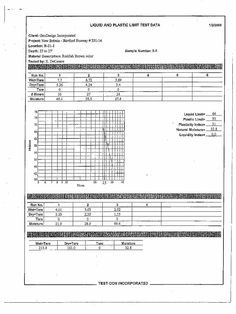
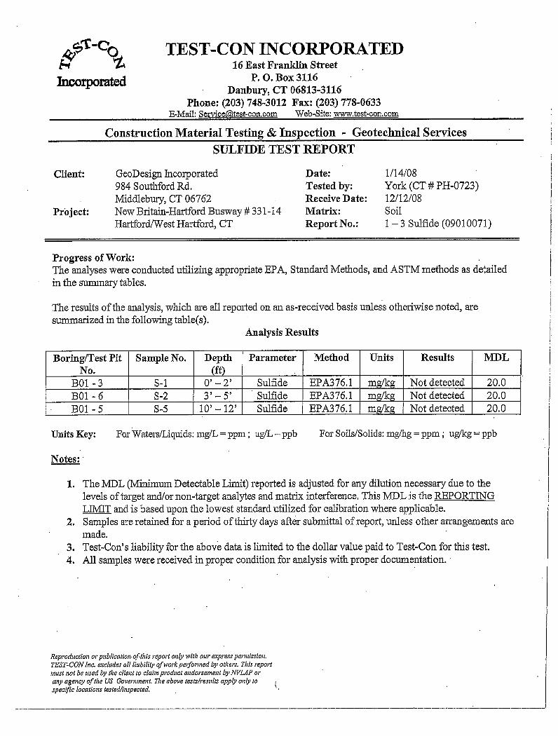


Appendix 6 2003 Geotechnical Laboratory
Testing


Appendix 7 Limitations

GEOTECHNICAL LIMITATIONS Explorations 1. The analyses and recommendations submitted in this report are based in part upon the data
obtained from widely spaced subsurface explorations. The nature and extent of variations between these explorations may not become evident until further explorations are made and construction occurs. If variations then appear evident, it will be necessary to reevaluate the recommendations of this report.
2. The generalized soil and bedrock profile described in the text is intended to convey trends in
subsurface conditions. The boundaries between strata are approximate and idealized and have been developed by interpretations of widely spaced explorations and samples; actual soil and bedrock transitions are probably more erratic. For specific information, refer to the boring logs.
3. The geologic and geomorphologic settings at this site are complex and the uncertain historic
site usage has resulted in the varied distribution and stress history of compressible soils across the site. Limited spacing of borings and lab testing can at best, only allow for estimates to be developed for duration and magnitude of consolidation settlements.
4. Water level readings have been made in the drill holes at times and under conditions stated
on the boring logs. These data have been reviewed and interpretations have been made in the text of this report. However, it must be noted that fluctuations in the level of the groundwater may occur due to variations in river levels, rainfall, temperature, and other factors occurring since the time measurements were made.
Review 5. In the event that any changes in the nature, design or location, of the proposed bridge the
conclusions and recommendations contained in this report shall not be considered valid unless the changes are reviewed and conclusions of this report modified or verified in writing by GeoDesign, Inc. It is recommended that this firm be provided the opportunity for a general review of design and specifications in order that earthwork and foundation recommendations may be properly interpreted and implemented in the design and specifications.
Use of Report 6. This report has been prepared for the exclusive use H.W. Lochner, Inc., the Connecticut
Department of Transportation (ConnDOT), and other members of the design team for specific application to the construction of Broad Street Over Amtrak and the New Britain - Hartford Busway located in Hartford, Connecticut, in accordance with generally accepted soil and foundation engineering practices. No other warranty, express or implied, is made.
7. This final design soil and foundation engineering report has been prepared for this project by
GeoDesign. This report is for design purposes only and is not sufficient to prepare an accurate bid. Contractors wishing a copy of the report may secure it with the understanding that its scope is limited to design considerations only.