table of contents construction … of contents construction specifications section no. section name...
TRANSCRIPT

TABLE OF CONTENTS CONSTRUCTION SPECIFICATIONS
Section No. Section Name Page ______________________________________________________________________ 01010 General Requirements 1 Delete Alternatives 2 31 10 00 Site Clearing 3-4 31 22 16 Earthwork and Grading 5-14 31 25 00 Erosion and Sedimentation Controls 15-16 32 12 16 Paving 17 32 16 10 Curbing 18-20 32 17 23 Painted Pavement Markings 21-22
SECTION 01010 – GENERAL REQUIREMENTS
PART 1 GENERAL
1.1 SUMMARY OF THE WORK: The intent of this project is to create a new parking lot at
the existing entrance to the Livermore Falls State Reservation, Pemigewasset River
access area off Livermore Road in Holderness, New Hampshire. The scope of the work
will include the following:
a. Removal of trees in the area designated for the new parking lot and entrance drive.
b. Grading of the parking area to facilitate sheet drainage of storm water as identified on
the plan.
c. Installation and grading of new sub base material under the area to be paved.
d. Installation of granite curb around traffic islands at the entrance, around the islands in
the middle of the parking area loop road, and along a designated section of the outside
of the parking loop.
e. Placement of a concrete slab foundation for a new toll booth to be provided and
installed by others.
f. Paving of the entrance drive and parking areas as indicated on the plan.
g. Painted paving markings to indicate direction of travel, parking stalls, and accessible
parking spaces.
h. Installation of a new State Park “gallows” sign to be provided by others.
i. Installation of a heavy timber State Park entrance gate to be provided by others.
j. Relocation of an existing public information kiosk as indicated on the plan.
k. Trenching for new electrical conduit to provide power to the new toll booth. This
will involve coordination with the State Parks electrician who will install the conduit
and locate the stub-up in the slab for the toll booth.
1.2 DOCUMENTS: These specifications and the plan entitled New Parking Lot off
Livermore Road Livermore State Forest shall comprise the contract documents.
1.3 PUBLIC ACCESS AND PROTECTION: The Livermore Falls area is a State
Reservation which is open to the public year round. Although the primary public use of
the area occurs during the summer months, the contractor shall be responsible throughout
the duration of the project for roping off or barricading sufficient area around the work
site to keep visitors and state personnel safe from construction hazards.
1.4 COORDINATION WITH THE DIVISION OF PARKS & RECREATION: The
contractor will coordinate in advance with the Division of Parks Central Region
Manager, Mr. Kevin Donovan (Office Tel: 603-323-8012) to arrange mutually acceptable
times for closing off or providing alternate access to areas normally accessible to the
public.
End of Section
Page 1, Construction Specifications

DELETE ALTERNATIVES:
Provide pricing on the bid proposal form for deleting the following from the scope of
work. The owner (State of NH DRED) will make a decision of whether to accept or reject each
alternative prior to giving a contract to the successful bidder.
Delete Alternative No. 1 Pavement Markings
Under this alternative no pavement marking work will be included in the contract.
Delete Alternative No. 2 Curbing
Under this alternative the installation of curbing around the traffic islands in the entrance
drive and in the middle of the parking loop are eliminated. However, the curb on the outside of
the traffic loop used to divert storm water drainage from the steep slope to the west of the site
will remain in the contract. The curb to remain will be 305 linear feet. Where the curb is deleted
around the traffic islands, blend the grade of the island down to meet the edge of paving at a
slope not greater than 2:1.
Delete Alternative No. 3 Paving
Under this alternative asphalt paving is deleted. The entrance drive and parking lot
surface will be compacted sand and gravel. Provide a subbase of 8” of crushed gravel and a
surface course of 6” of sand and gravel compacted to 95% maximum density.
End of Section
Page 2, Construction Specifications
SECTION 31-10-00 SITE CLEARING
PART I GENERAL
1.1 SCOPE OF WORK
A. Protect existing trees and vegetation to remain. Special care shall be taken to protect
trees designated to be retained in the traffic island in the main parking loop.
B. Removal of trees in the areas to be developed for the entrance drive and parking area.
Trees to be removed have been marked with paint on the trunks.
C. Clearing and grubbing in designated areas.
D. Disposal of material from clearing, grubbing, and tree removal in approved off-site
disposal areas.
E. Filling of voids and excavations resulting from site clearing work.
F. Removal of abandoned utilities.
PART II PRODUCTS
2.1 TREE PROTECTION FENCING: Fencing shall be an orange plastic web fence, 4 feet
high (min) supported by wood stakes (1”x1”x6’ long) driven 2 feet into the ground. Stakes shall
be spaced approximately 8 feet on center.
PART III EXECUTION
3.1 PROTECTION
A. The contractor shall flag the limits of the area to be cleared as shown on the drawing
and determined by field survey with marked stakes acceptable to the Division of
Parks designated Project Manager. Trees to remain shall be clearly identified during
the staking process. The clearing limits shall be inspected and approved by the Project
Manager before site clearing commences.
B. Before clearing begins. Protect designated trees to remain with tree protection fencing
in order to prevent damage to the trunks, foliage and root systems by construction
equipment and procedures
C. Place protection fencing as required to protect other plants, adjacent property, areas to
remain uncleared, monuments and existing improvements from damages. Place
fencing around the existing well head on the site.
D. Maintain the protection fencing for the duration of construction operations. Fencing
shall be removed from the site at the completion of construction operations and
disposed of in accordance with all applicable regulations.
Page 3, Construction Specifications
3.2 UTILITIES
A. Notify all corporations, companies, individuals or local authorities owning or having
jurisdiction over utilities running to, through or across areas to be affected by site
clearing operations.
B. For utilities to be disconnected, have utility service disconnected in accordance with
the requirements of the utility owner.
3.3 CLEARING & GRUBBING
A. Clearing shall include cutting, removal, and offsite disposals of trees, bushes, shrubs,
stumps, fallen timber, brush, refuse, trash, fencing, and other incidental materials not
required for re-use on the site.
B. The contractor shall grub the area within the clearing limits to completely remove
stumps and root systems except for those from trees to remain.
C. Depressions, excavations and voids resulting from the removal of stumps or roots
shall be filled with suitable material and compacted as specifies under SECTION
31 30 00 – EARTHWORK
D. Grade surface of filled areas to match adjacent grades and slope to provide surface
drainage
3.4 REMOVAL & ABANDONMENT OF UTILITIES
A. There is a well on the site which will remain and be used by DES as a ground water
monitoring station. The well apparently had underground electrical service to the
pump when it was installed. Verify that the utility service to the well has been
disconnected. If the underground electrical cable or conduit is encountered during
excavation, remove the services back to the limits of clearing and abandon the
remaining lines in accordance with the utility’s recommended procedures.
3.5 DISPOSAL
A. Remove from the site all materials resulting from site clearing operations and dispose
of in accordance with all applicable regulations.
B. No burning of materials on site will be allowed.
End of Section
Page 4, Construction Specifications

SECTION 31 22 16 – EARTHWORK AND GRADING
PART I GENERAL
1.1 SUMMARY OF THE WORK: The work of this section includes but is not necessarily
limited to:
A. Excavation, fill and backfill as indicated or required including compaction
to the lines and grades on the plan
B. Excavation and the offsite disposal of unsuitable or excess materials
C. Rough grading, including placement, moisture conditioning, and compaction of fills
and backfills.
D. Placement of base and subbase course materials under pavements, slabs and footings
including compaction.
E. Fine grading to make the subgrade, the area under the surface course, and the
shoulders adjacent to the paved areas conform to the lines shown on the plan or
established by the project engineer.
F. Trench excavation, bedding and backfill for foundations and utilities including
compaction.
G. Obtain and pay fees for all required permits, licenses, and approvals of appropriate
municipal and utility authorities prior to commencing the work of this section.
H. All erosion control measures shall be installed prior to earthwork operations and shall
be maintained according to the plan and other sections of the specification. Provide
facilities, labor, materials, tools, equipment and related work necessary to provide and
maintain erosion control during construction operations.
I. Contractor shall be responsible for notifying all affected utility companies and Dig
Safe before starting work.
1.2 QUALITY ASSURANCE
A. TESTING: The contractor shall retain and pay for the services of an independent
testing firm to test for compaction of the subbase material prior to paving.
a. The density of sand courses shall be determined by AASHTO T191 (Sand
Cone method) AASHTO T204 (Drive Cylinder Method) or AASHTO T238
(Nuclear Methods) The density shall not be less than 95% of the maximum
density determined in accordance with AASHTO T99 (Standard Proctor Test).
b. The density of gravel and crushed gravel courses shall be determined by
AASHTO T191 (Sand-cone method) or AASHTO T238 (Nuclear Methods).
The density of crushed stone base course shall be determined by AASHTO
234 (Nuclear Methods). The density shall not be less than 95% of the
maximum density determined in accordance with AASHTO T99 (Standard
Proctor Test).
Page 5, Construction Specifications

PART II PRODUCTS 2.01 MATERIALS
A. Subgrade is the material in excavation (cuts) and fills located below subbase, base
course layer for slabs, sidewalks, pavement, and other improvements.
B. Common Fill/Ordinary Borrow shall be friable soil containing no stone greater than
two-thirds (2/3) the loose lift thickness with a maximum stone size of twelve (12)
inches in diameter. The material shall be essentially free of trash, ice snow, tree
stumps, roots, and organic materials. The soil shall contain no more than 15 percent
passing the #200 sieve.
C. Gravel shall meet the requirements of NHDOT 304.2 and shall be modified so that
the maximum size of stone particles shall not exceed three-fourths of the compacted
thickness of the layer being placed; one and one half inches (1-1/2”) maximum size
where placed as pipe bedding and backfill up to 24 inches above pipe; and elsewhere
two thirds (2/3) the loose lift thickness.
Crushed Gravel shall meet the requirements of NHDOT 304.3
E. Sand shall consist of clean, inert, hard, durable grains of quartz or other hard,
durable rock, free from loam or clay, surface coatings and deleterious materials.
Page 6, Construction Specifications

1 The allowable amount of material passing a No. 200 sieve as determined by
AASHTO-T11 or ASTM D422 shall not exceed 10 percent by weight. The maximum
particle size shall be ¼ inch. (i.e. 100 percent passing the number 4 sieve)
2. In addition to the above criteria when sand is used for bedding concrete
pavers and for utility bedding it shall conform to the following gradation:
Sieve (ASTM D422) Percent Passing
by Weight
No. 4 100
No. 8 80 - 95
No. 16 55 - 85
No. 50 0 - 35
No. 200 0 - 5
Bank Run Sand shall meet the requirements of NHDOT 304.1.
H. Crushed Stone shall be composed of durable crushed rock consisting of angular
fragments, free from a detrimental quantity of thin, flat, elongated pieces or shall be
durable crushed gravel stone obtained by artificial crushing of gravel boulders or
fieldstone.
1. The crushed stone shall be free from clay, loam, or deleterious material.
Page 7, Construction Specifications

2. Crushed stone shall conform to the following gradation:
Percent Passing by Weight
Sieve Size 1/2-inch Stone 3/4-inch Stone
1 inch - 100 3/4 inch - 90 - 100 5/8 inch 100 - 1/2 inch 85 - 100 10 - 50 3/8 inch 15 - 45 0 - 20 No. 4 - 0 - 5 No. 8 0 - 5 -
Percent Passing by Weight
Sieve Size 1-1/2-inch Stone 2-inch Stone
2 inch 100 90 - 100 1-1/2 inch 95 - 100 - 1-1/4 inch - 25 - 50 1 inch 35 - 70 - 3/4 inch 0 - 25 0 - 15 1/2 inch - -
Percent Passing by Weight Sieve Size NHDOT 304.4 NHDOT 304.5
3-½ inch - 100 3-inch - 85-100 2-inch 100 - 1-½ inch 85-100 60-90 3/4 inch 45-75 40-70 No. 4 10-45 15-40 No. 200 0-5 0-5
H. Washed Crushed Stone for Stormwater Recharge shall be composed of durable
crushed rock consisting of angular fragments, free from a detrimental quantity of
thin, flat, elongated pieces or shall be durable crushed gravel stone obtained by
artificial crushing of gravel boulders or fieldstone. The crushed stone shall be free
from clay, loam, or deleterious material.
Page 8, Construction Specifications
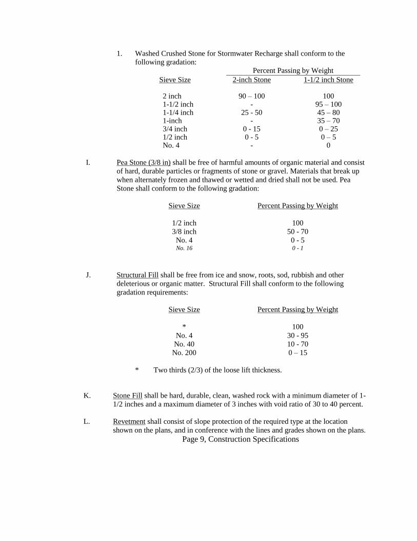
1. Washed Crushed Stone for Stormwater Recharge shall conform to the
following gradation: Percent Passing by Weight
Sieve Size 2-inch Stone 1-1/2 inch Stone
2 inch 90 – 100 100 1-1/2 inch - 95 – 100 1-1/4 inch 25 - 50 45 – 80 1-inch - 35 – 70 3/4 inch 0 - 15 0 – 25 1/2 inch 0 - 5 0 – 5 No. 4 - 0
I. Pea Stone (3/8 in) shall be free of harmful amounts of organic material and consist
of hard, durable particles or fragments of stone or gravel. Materials that break up
when alternately frozen and thawed or wetted and dried shall not be used. Pea
Stone shall conform to the following gradation:
Sieve Size Percent Passing by Weight
1/2 inch 100
3/8 inch 50 - 70
No. 4 0 - 5 No. 16 0 - 1
J. Structural Fill shall be free from ice and snow, roots, sod, rubbish and other
deleterious or organic matter. Structural Fill shall conform to the following
gradation requirements:
Sieve Size Percent Passing by Weight
* 100
No. 4 30 - 95
No. 40 10 - 70
No. 200 0 – 15
* Two thirds (2/3) of the loose lift thickness.
K. Stone Fill shall be hard, durable, clean, washed rock with a minimum diameter of 1-
1/2 inches and a maximum diameter of 3 inches with void ratio of 30 to 40 percent.
L. Revetment shall consist of slope protection of the required type at the location
shown on the plans, and in conference with the lines and grades shown on the plans.
Page 9, Construction Specifications

1. Riprap. Riprap shall consist of a protective covering of angular shaped stones
laid on slopes in front of structures, wingwalls, piers, and elsewhere as
required, to insure protection of structures and embankments.
a. Riprap shall be sound, durable rock, which is angular in shape.
Rounded stones, boulders, sandstone, or similar soft stone or relatively
thin slabs will not be acceptable. Each stone shall weigh not less than
50 pounds and at least 75% of the volume shall consist of stones
weighing not less than 500 pounds each. The remainder of the stones
shall be so graded that when placed with the larger stones the entire
mass will be compact.
2. Stone for Pipe Ends and Energy Dissipaters: Stone for pipe ends and energy
dissipaters shall be sound, durable rock, which is angular in shape. Rounded
stones, boulders, sandstone or similar stone or relatively thin slabs will not be
acceptable. Stones shall be so graded that when placed the entire mass will be
compact. The median diameter or angular shape stone size shall be graded so
50 percent of the stones are larger than the d50 size and 50 percent smaller,
and the largest stone is 1½ times the d50.
The minimum stone size shall be ½ of the d50 size; and the minimum depth
of stone shall be 6 inches or 1.5 times the largest stone size (whichever is
greater).
Unless otherwise specified on the plans, stone for pipe ends shall conform to
the following parameters:
Parameter Size
d50 8-inches
Max. Stone 12-inches
Min. Stone 6-inches
Min. Thickness 18-inches
3. Slope Paving: Slope paving shall consist of angular shaped stones, having a
reasonable flat face, carefully placed on slopes to insure the slope is protected.
a. Stone for slope paving shall be sound, angular in shape, and free from
structural defects. Each stone shall have one reasonably flat face and a
thickness perpendicular to the face of not less than 6 inches, which
shall be the least dimension of the stone.
Page 10, Construction Specifications

b. Approximately 60 percent of the stones shall vary from 2 to 3 cubic
feet each in volume and the remainder of the stones shall each be from
1 to 2 cubic feet in volume.
4. Channel Paving and Grouted Channel Paving. Channel Paving of the type
specified shall be placed as protective covering along the slopes around
culvert inlets or outlets, around foundations, structure and dikes.
a. Stones for Channel Paving and Grouted Channel Paving shall be
sound, approved quality angular blocks, as nearly rectangular or
cubical as practicable. Rounded stones or relatively thin slabs will not
be acceptable. At least 75 percent of the volume shall consist of stones
weighing at least 200 pounds each. The remainder of the stones shall
be so graded that when placed with the larger stones a compact mass
will result.
5. Filter Layer. The Filter Layer of stone shall be used under Riprap, Stone for
Pipe Ends, Slope Paving, and Channel Paving (grouted or non-grouted). The
Filter Layer shall be minimum of 6-inches in thickness.
6. Filter Fabric used with riprap, stone for pipe ends, slope paving, or channel
paving (grouted or ungrouted) shall be as Mirafi 600X or equivalent.
M. Filter Fabric / Geotextiles:
1. Geotextile Fabric shall be used to prevent soil intrusion into drains and/or
assist in stabilizing soil subgrades to be laid on approved soil subgrades prior
to placement of fill materials.
a. Contractor shall use Mirafi 140N or equivalent filter fabric in drainage
recharge systems, underdrain systems between crushed stone and granular
soils, leaching areas, or where indicated on the plans.
P. Controlled Low Strength Material or Controlled Density Fill:
1. Controlled low strength material or controlled density fill shall be a cement
concrete backfill material that flows like a liquid, supports like a solid when
cured, and levels without tamping or vibrating to reach 100 percent
compaction. The material shall be used primarily as a backfill in lieu of
compacted fill. The material shall be proportioned to yield a 28—day
minimum compressive strength of 200 pounds per square inch. The material
shall be produced and installed in accordance with ACI 229R, and ACI
116R, with a mix formulation to be approved by the Engineer or
Geotechnical Consultant prior to placement of the material in the project.
Page 11, Construction Specifications
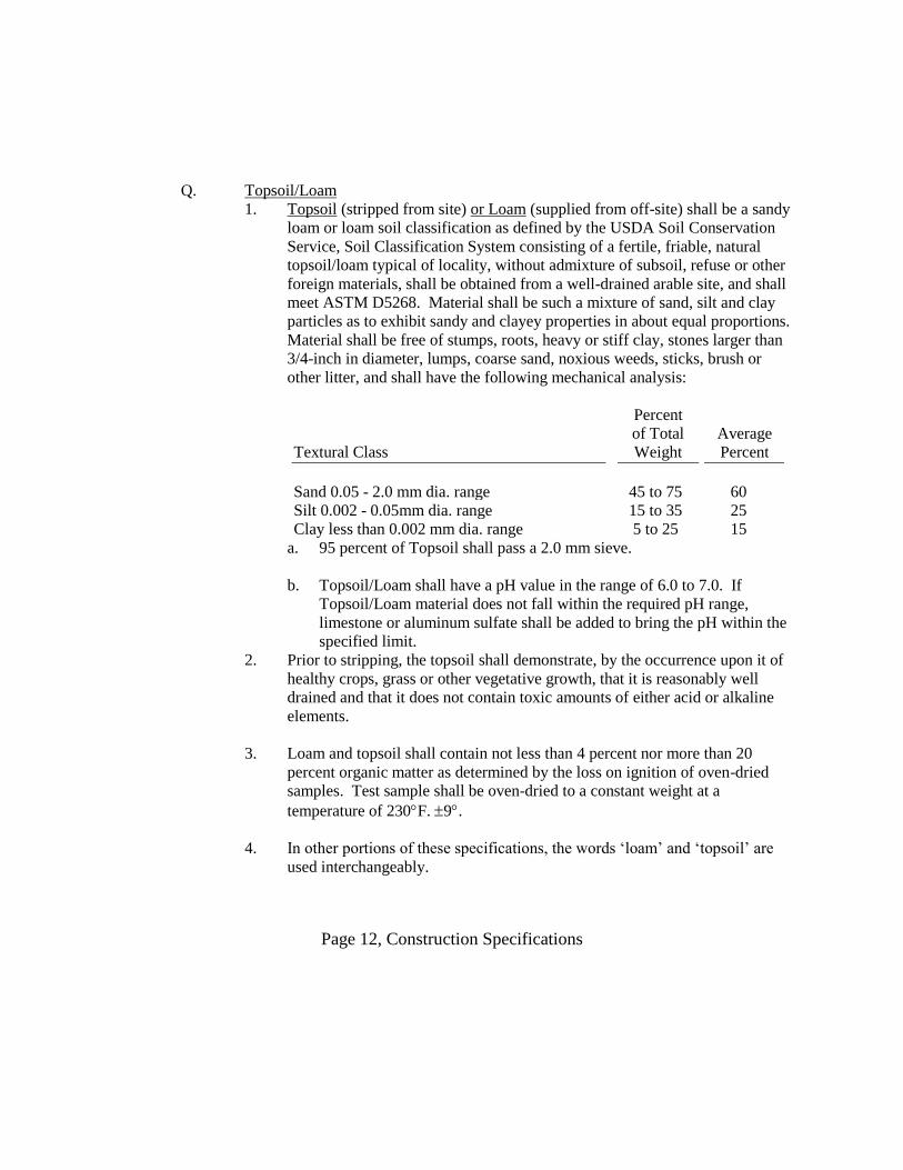
Q. Topsoil/Loam
1. Topsoil (stripped from site) or Loam (supplied from off-site) shall be a sandy
loam or loam soil classification as defined by the USDA Soil Conservation
Service, Soil Classification System consisting of a fertile, friable, natural
topsoil/loam typical of locality, without admixture of subsoil, refuse or other
foreign materials, shall be obtained from a well-drained arable site, and shall
meet ASTM D5268. Material shall be such a mixture of sand, silt and clay
particles as to exhibit sandy and clayey properties in about equal proportions.
Material shall be free of stumps, roots, heavy or stiff clay, stones larger than
3/4-inch in diameter, lumps, coarse sand, noxious weeds, sticks, brush or
other litter, and shall have the following mechanical analysis:
Textural Class
Percent
of Total
Weight
Average
Percent
Sand 0.05 - 2.0 mm dia. range 45 to 75 60
Silt 0.002 - 0.05mm dia. range 15 to 35 25
Clay less than 0.002 mm dia. range 5 to 25 15
a. 95 percent of Topsoil shall pass a 2.0 mm sieve.
b. Topsoil/Loam shall have a pH value in the range of 6.0 to 7.0. If
Topsoil/Loam material does not fall within the required pH range,
limestone or aluminum sulfate shall be added to bring the pH within the
specified limit.
2. Prior to stripping, the topsoil shall demonstrate, by the occurrence upon it of
healthy crops, grass or other vegetative growth, that it is reasonably well
drained and that it does not contain toxic amounts of either acid or alkaline
elements.
3. Loam and topsoil shall contain not less than 4 percent nor more than 20
percent organic matter as determined by the loss on ignition of oven-dried
samples. Test sample shall be oven-dried to a constant weight at a
temperature of 230F. 9.
4. In other portions of these specifications, the words ‘loam’ and ‘topsoil’ are
used interchangeably.
Page 12, Construction Specifications

2.02 USE OF MATERIALS
A. Use of materials shall be as described below and as shown on the plans. Further
details can be found in the project plans. Combinations or layering of materials may
be necessary in certain instances such as for detention embankments, subsurface
disposal areas, and riprap walls as examples.
1. Common/Ordinary Fill: Use common/ordinary fill for general grading as
backfill, and as embankment fill in areas outside the building and pavement
limits. Stones larger than twelve inches (12") shall be removed prior to
compaction.
2. Gravel (NHDOT 304.2): Use for pipe bedding backfill and backfill below
pavement and slab as base course layer. Use for material placed "in the wet".
Use for backfill behind retaining walls and retaining structures. Use for pipe
and utility bedding.
3. Crushed Gravel (NHDOT 304.3): Use crushed gravel for base course
material under pavement and concrete slabs; and under/around curbs.
4. Sand: Use for conduit bedding and initial backfill, and gas line bedding and
backfill. Use for bedding and backfill of direct burial cables and/or flexible
piping. Use for bedding and filling joints for concrete unit pavers.
5. Bank Run Sand (NHDOT 304.1): Use for On-Site Disposal System
Leaching Area, where fill is required from the naturally-occurring, inorganic
layer to the base of the Septic Sand Fill material as shown on the Drawings.
6. Crushed Stone: Use crushed stone as a filter material around perforated pipe
and as bedding for piping under wet subgrade conditions.
87. Washed Crushed Stone: Use washed crushed stone in stormwater recharge
system as the material around perforated pipe.
8. Pea Stone (3/8 in): Use as a choke layer to prevent soil migration between
dissimilar soil materials.
9. Structural Fill: Use structural fill below subgrade elevation in building areas
such as beneath floor slabs, foundations, and in other soil bearing situations.
Structural fill shall also be used for backfill against building foundations and
frost walls. Use structural fills below pavement gravel base course.
. Blast Rock Fill and Choke Stone: Refer to Section 2.01 for definition and
use.
11. Stone Fill: Use stone fill as additional storage medium for underground
stormwater exfiltration trenches or pits.
Page 13, Construction Specifications
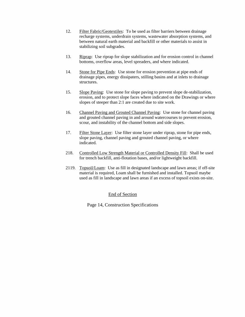
12. Filter Fabric/Geotextiles: To be used as filter barriers between drainage
recharge systems, underdrain systems, wastewater absorption systems, and
between natural earth material and backfill or other materials to assist in
stabilizing soil subgrades.
13. Riprap: Use riprap for slope stabilization and for erosion control in channel
bottoms, overflow areas, level spreaders, and where indicated.
14. Stone for Pipe Ends: Use stone for erosion prevention at pipe ends of
drainage pipes, energy dissipaters, stilling basins and at inlets to drainage
structures.
15. Slope Paving: Use stone for slope paving to prevent slope de-stabilization,
erosion, and to protect slope faces where indicated on the Drawings or where
slopes of steeper than 2:1 are created due to site work.
16. Channel Paving and Grouted Channel Paving: Use stone for channel paving
and grouted channel paving in and around watercourses to prevent erosion,
scour, and instability of the channel bottom and side slopes.
17. Filter Stone Layer: Use filter stone layer under riprap, stone for pipe ends,
slope paving, channel paving and grouted channel paving, or where
indicated.
218. Controlled Low Strength Material or Controlled Density Fill: Shall be used
for trench backfill, anti-flotation bases, and/or lightweight backfill.
2119. Topsoil/Loam: Use as fill in designated landscape and lawn areas; if off-site
material is required, Loam shall be furnished and installed. Topsoil maybe
used as fill in landscape and lawn areas if an excess of topsoil exists on-site.
End of Section
Page 14, Construction Specifications

SECTION 31 25 00– EROSION AND SEDIMENTATION CONTROLS
PART I – GENERAL
1.1 Summary of the work: Install silt fence and hay bales at locations as shown on the
drawings.
PART II – MATERIALS
2.1 Silt fence shall consist of geotextile filter fabric made from polypropylene, polyester,
or other approved polymeric chemically stable material and be resistant to ultraviolet
radiation degradation for at least 12 months. Silt retention capacity shall be no less
than 75 percent of silt and suspended solids. Use Mirafi 100x or approved equivalent.
2.2 Hay bales shall be approx. 2’- 6” in length banded with a minimum of 2 wire ties or
nylon tapes. Stakes for hay bales shall be 1 ½” x 1 ½” x 4’ long wood or approved
equivalent.
PART III – EXECUTIVE
3.1 Silt Fence:
A. Posts for silt fence shall be either wood or steel. Wood posts shall be sound
quality hardwood with a minimum cross sectional area of 3 square inches.
Steel posts shall be standard or “U” section weighing not less than 1 pound
per linear foot with projections for fastening wire to the fence. Maximum post
spacing shall be 10 feet.
B. Support fence for silt fence, if required, shall be a minimum of 14.5 gauge
woven wire with a maximum 6” mesh.
C. Installation: When two sections of filter fabric adjoin each other, they shall be
overlapped by 6”, folded and stapled at a post. Support fence, when required,
shall be fastened securely to the fence posts with staples or wire ties. Filter
fabric shall be fastened to the support fence, when support fence is required,
with ties spaced every 2 feet longitudinally at the top, mid-section, and
bottom.
D. Care shall be taken to maintain the silt fence in a functional condition at all
times during the construction period.
E. The contractor shall remove the silt fence after all work has been completed
and it is no longer needed or as ordered. Sediment deposits that are removed
or left in place after the fabric has been removed shall be graded to conform to
the existing topography and shall be vegetated.
Page 15, Construction Specifications
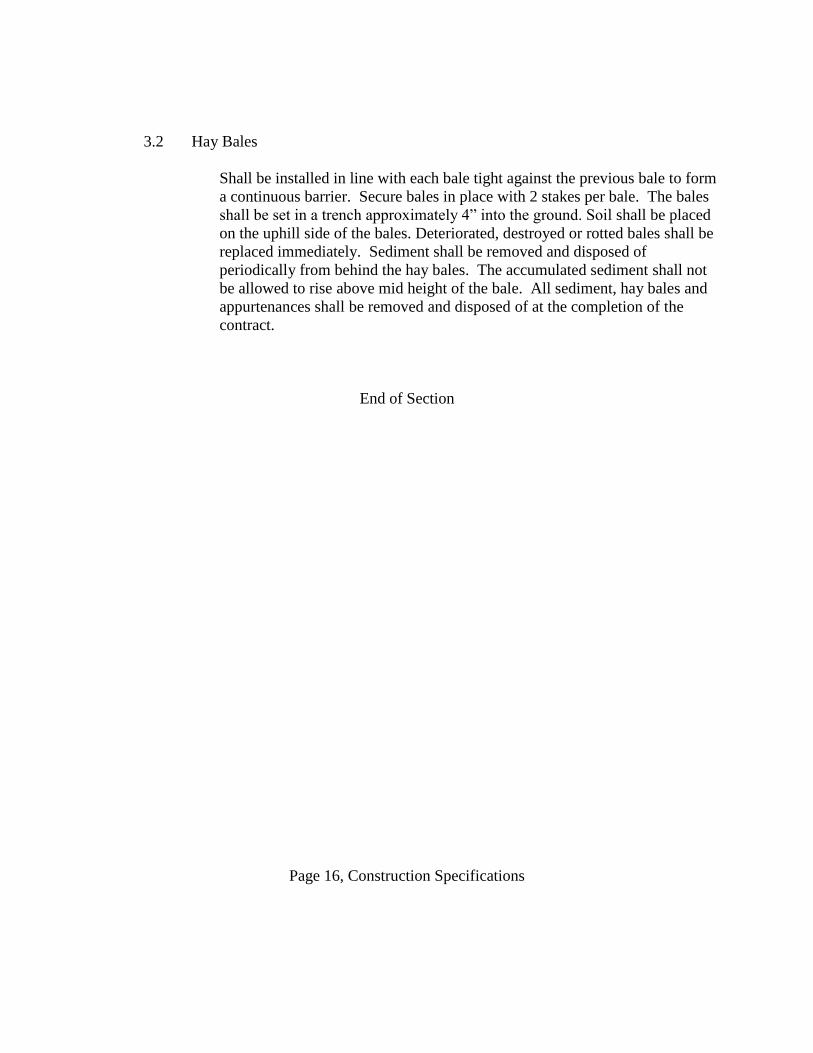
3.2 Hay Bales
Shall be installed in line with each bale tight against the previous bale to form
a continuous barrier. Secure bales in place with 2 stakes per bale. The bales
shall be set in a trench approximately 4” into the ground. Soil shall be placed
on the uphill side of the bales. Deteriorated, destroyed or rotted bales shall be
replaced immediately. Sediment shall be removed and disposed of
periodically from behind the hay bales. The accumulated sediment shall not
be allowed to rise above mid height of the bale. All sediment, hay bales and
appurtenances shall be removed and disposed of at the completion of the
contract.
End of Section
Page 16, Construction Specifications
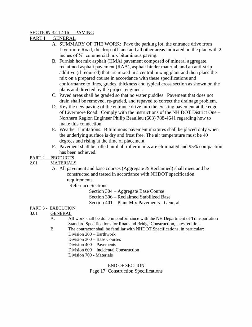
SECTION 32 12 16 PAVING
PART I GENERAL
A. SUMMARY OF THE WORK: Pave the parking lot, the entrance drive from
Livermore Road, the drop-off lane and all other areas indicated on the plan with 2
inches of ¾” commercial mix bituminous paving.
B. Furnish hot mix asphalt (HMA) pavement composed of mineral aggregate,
reclaimed asphalt pavement (RAA), asphalt binder material, and an anti-strip
additive (if required) that are mixed in a central mixing plant and then place the
mix on a prepared course in accordance with these specifications and
conformance to lines, grades, thickness and typical cross section as shown on the
plans and directed by the project engineer.
C. Paved areas shall be graded so that no water puddles. Pavement that does not
drain shall be removed, re-graded, and repaved to correct the drainage problem.
D. Key the new paving of the entrance drive into the existing pavement at the edge
of Livermore Road. Comply with the instructions of the NH DOT District One –
Northern Region Engineer Philip Beaulieu (603) 788-4641 regarding how to
make this connection.
E. Weather Limitations: Bituminous pavement mixtures shall be placed only when
the underlying surface is dry and frost free. The air temperature must be 40
degrees and rising at the time of placement
F. Pavement shall be rolled until all roller marks are eliminated and 95% compaction
has been achieved. PART 2 – PRODUCTS
2.01 MATERIALS
A. All pavement and base courses (Aggregate & Reclaimed) shall meet and be
constructed and tested in accordance with NHDOT specification
requirements.
Reference Sections:
Section 304 – Aggregate Base Course
Section 306 – Reclaimed Stabilized Base
Section 401 – Plant Mix Pavements - General PART 3 - EXECUTION
3.01 GENERAL
A. All work shall be done in conformance with the NH Department of Transportation
Standard Specifications for Road and Bridge Construction, latest edition.
B. The contractor shall be familiar with NHDOT Specifications, in particular:
Division 200 – Earthwork
Division 300 – Base Courses
Division 400 – Pavements
Division 600 – Incidental Construction
Division 700 - Materials
END OF SECTION
Page 17, Construction Specifications

SECTION 32 16 10 CURBING
PART I GENERAL
1.1 SUMMARY OF THE WORK:
A. Furnish and install granite curb around traffic islands at the entrance drive and
around islands in the middle of the parking lot, along a designated section of the
outside of the parking loop, and as indicated on the plan.
B. Provide all associated items and perform all operations required to complete the
curbing installation including surface preparations, concrete support, jointing
and finishing.
1.2 DELIVERY STORAGE & HANDLING
A. Curbing shall be protected against staining, chipping and other damage. Cracked,
badly chipped, or stained units will be rejected.
PART II PRODUCTS 2.1 GRANITE CURB
A. Granite curb shall be light gray in color, free from seams and other structural
imperfections or flaws which would impair its structural integrity, and of a smooth
splitting appearance. Natural color variation characteristic of the deposit from
which the curb is obtained will be permitted.
B. Whenever curbing is sawed, all surfaces that are to be exposed shall be thoroughly
cleaned and any iron rust or iron particles removed by sandblasting or other methods
approved by the Engineer and any saw mark in excess of 1/8 inch shall be removed.
C. Dimensions
1. The stones for the several types of granite curb shall be cut to the dimensions
and curvature hereinafter needed:
Minimum Width Minimum Width
Type Length at Top Depth at Bottom
Highway 3 feet* 5 inches 16 to 18 inches 3 inches
Site 3 feet 5 inches 15-17 inches 3 inches
* Length of stones shall be 3 to 10 feet with 50 percent of sections to be 5
feet or greater.
2. Stones to be set on a radius of less than 21 feet shall be cut to the required
curvature, unless otherwise approved and, except for making closures, shall
be of the following minimum lengths:
Page 18, Construction Specifications

Radius Maximum Length
21 feet
22 feet to 28 feet
29 feet to 35 feet
36 feet to 42 feet
43 feet to 49 feet
50 feet to 56 feet
3 feet
4 feet
5 feet
6 feet
7 feet
8 feet
57 feet to 60 feet 9 feet
Over 60 feet 10 feet
Note: Adjoining stones shall have the same or approximately the same length.
D. Finish
1. Granite curb shall have a top surface free from wind, and shall be peen
hammered or sawed to an approximately true plane, and shall have no
projections or depressions greater than 1/8 inch. The front and back arris
lines shall be pitched straight and true and there shall be no projection on the
back surface for 3 inches down from the top which would exceed a batter of
4 inches to 1 foot.
a. The front face shall be at right angles to the planes of the top and ends
of the curb unit and shall be smooth quarry split, free from drill holes
and with no projection of more than 1 inch and no depression of more
than 1/2 inch measured from the vertical plane of the face through the
arris or pitch line for a distance down from the top of 8 inches. For
the remaining distance, there shall be no projection or depression
greater than 1 inch measured in the same manner.
b. The ends of all stones shall be square with the planes of the top and
face of the curb so that when the stones are placed end to end as
closely as possible, no space shall show in the joint at the top and face
of more than 1/2 inch for the full width of the top and for 8 inches
down on the face; after which the end may break back not over
8 inches from the plane of the joint. The arris formed by the
intersection of the plane of the joint with the planes of the top and
exposed faces shall have no variation from the plane of the top and
exposed faces greater than 1/8 inch.
2.2 CEMENT MORTAR: Cement mortar shall be composed of one part Portland cement and
two parts of sand by volume with sufficient water to form a workable mix. Cement shall be
Portland Cement ASTM C150, TYPE II.
Page 19, Construction Specifications

PART III EXECUTION
3.1 GENERAL: Trenching, excavation, backfilling, and compaction shall be completed in
accordance with Section 31 00 00 EARTHWORK
3.2 GRANITE CURB INSTALLATION:
A. Excavation shall extend 6 inches below and behind curb. The ground base shall
be placed in the excavated area, graded and compacted to above the proposed
curb subgrade.
B. Curbing and curb corners shall be set on additional gravel spread upon the
foundation. All spaces under the curb and curb corners shall be filled with gravel
thoroughly compacted so that the curb will be completely supported throughout
its length. The curb shall be set at the line and grade required on the plan unless
otherwise directed.
C. Curb and curb corners shall be fitted together as closely as possible.
D. Immediately after the curb is set, the space between it and the wall of the trench
shall be filled with gravel thoroughly tamped to a depth of 6 inches with care
being taken not to affect the line or grade of the curb. The trench shall continue to
be filled with gravel and compacted in 6 inch lifts until grade is achieved.
E. The joints between curbstones both front and back shall be carefully filled with
cement mortar and neatly pointed on the top and front (exposed) portions. After
pointing, the curbstones shall be cleaned of all excess mortar that may have been
forced out of the joints.
F. The ends of the stone curb shall be cut at a bevel or rounded as shown in the
drawings.
Page 20, Construction Specifications
SECTION 32 17 23 PAINTED PAVEMENT MARKING
PART I GENERAL
1.1 SUMMARY OF THE WORK: Apply pavement marking paint to indicate parking spaces,
to designate accessible parking spaces, and to provide direction of travel arrows.
1.2 QUALITY CONTROL
A. Perform the work in accordance with the NH DOT standards (section 632
standard specifications) and Manual of Uniform Traffic Control Devices)
B. Applicator qualifications: The painting sub-contractor shall be a company
specializing in painted pavement markings with at least 3 years documentable
experience.
PART II MATERIALS
A. Pavement markings shall be white Traffic Marking paint as manufactured by
Sherwin Williams Co:
Setfast Acrylic Latex Traffic Marking Paint White
(SW TM2160) or approved equal.
B. Paint: Pavement paint shall be ready mixed, conventional, fast drying,
waterborne traffic paint. It shall be lead-free, non-toxic, NASSHTO Test Deck
minimum retro-reflectance of 6 or more after being in place for 9 months.
1. Pigment percentage by weight shall be 60 plus or minus 2%
2. Vehicle percentage by weight shall be 40 plus or minus 2%
3. Non-volatile percentage by weight of paint shall be 76
4. Weight per gallon shall be a minimum of 13 pounds
5. Viscosity shall be 80-95 Kred units at 77 degrees F
6. Drying time: 125 minutes maximum in accordance with ASTM D1640
(15 mils wet thickness at 90% relative humidity and 72 degrees F)
7. VOC (volatile organic compound) content: one lb. / gal. maximum.
C. The marking paint must be able to be applied on pavement with a surface
temperature down to 40 degrees Fahrenheit.
D. Paint the parking space lines 4 inches wide in the locations as indicated on the
plan.
E. Perform the work in accordance with NH DOT standards.
Page 21, Construction Specifications
PART III EXECUTION
3.1 Pavement must be clean and free of dust or dirt before applying paint.
3.2 Paving markings shall be applied in accordance with the layout shown on the drawings.
3.3 No paint shall be applied to new bituminous pavement until the top course has cured at
least one week.
3.4 SPECIAL MARKINGS
A. All parking stall lines shall be single lines, 4” wide, and white in color. Parking stall
markings shall be straight with sharp corners and clean edges.
B. Accessible parking spaces: Stencil accessible space with the standard accessible space
logo in white paint on a blue background.
C. Stripe the aisles between accessible space with 45 degree angle stripes at 1 foot on
center, 4” wide, white in color.
D. Direction arrows: Stencil 10 directional arrows in white paint as indicated in the
drawings or as directed by the project manager.
Page 22, Construction Specifications