table of contents pagedownload.normanwindowcoverings.com/document/service... · any contents within...
TRANSCRIPT


Disclaimer: Norman International, Co. reserves all rights on updating or modification of any contents within this documentation without prior notification.
Effective 2008
Table of Contents Page
a. Features & Benefits ND a-1
b. Colors & Louvers ND b-1
c. Stiles ND c-1
d. Panel Configurations ND d-1
e. Frame Styles ND e-1
f. General Product Specifications ND f-1
g. Tilt Rods ND g-1
h. Divider Rails ND h-1
i. Hardware ND i-1
j. Track Shutters ND j-1
k. Special Options ND k-1
l. Specialties ND l-1
n. Appendix ND n-1
o. RF Motorized Shutter ND o-1

Features and Benefits
ND a-1
• Brings a touch of timeless elegance to your home. The textured finish of Normandy shutters blends the tranquility of nature with distinctive luxury.
• Normandy is treated with our exclusive Prescription Wood Conditioning™ technique
according to the moisture content of the final installation location to reduce post-installation shrinking and swelling.
• A wide range of frames with inserts that keep installation screws out of sight for a
clean and decorative look to match any style and preference. • Reinforced engineered stiles -- Multiple layers of wood bonded together to reinforce
durability to the core of the stile, which results in a robust support system for the shutter panel.
• Multiple stile options available in various sizes to accommodate different window
configurations. Astragal (solid color shutters only) or Rabbet stiles provide a natural light block between panels.
• Employs mortise and tenon joinery that resists shear and racking forces endured by
shutters and ensures prolonged stability and durability.
• Quick and easy on-site installation with the pre-installed magnets and hinges, as well as pre-mitered frames and slotted keyholes.
• Labor-intensive hand finishing process involves multiple sequences of sanding
and coating with fine layers of stain or paint for a brilliant, lustrous finish. • Personalize shutters with special options. Choose from hidden or offset tilt rods,
double-hung panels, café shutters, track systems, specialty shapes and many more.
• Special panel and frame designs are finely crafted to accommodate unique window configurations. Create unity or attract attention with Normandy’s exclusive decorative elements.
• Available in classic paint and radiant stain that harmonize into the style of any
home. • A guarantee of Norman’s exemplary quality with a lifetime limited warranty on
materials and workmanship.
ND a-1

Colors & Louvers
Colors available till June 30, 2013
Color Code Color Name Note
011 Cameo Discontinue on June 30, 2013
013 Bisque Discontinue on June 30, 2013
103 Maple Sugar Discontinue on June 30, 2013
105 Hermitage Green Discontinue on June 30, 2013
206 Pecan Discontinue on June 30, 2013
214 Cocoa Discontinue on June 30, 2013
222 Light Pine Discontinue on June 30, 2013
224 Mellow Beech Discontinue on June 30, 2013
226 Chestnut Discontinue on June 30, 2013
Solid Colors Louvers 001 Pure White 003 Silk White 004 Bright White 006 Pearl 009 Creamy 012 Crisp Linen 030 Moondust 046 Ice 000 Primed
Stain Colors* 108 Rustic Gray 110 Limed White
205 Goldenrod 211 Cherry 221 Black Walnut 227 Red Oak 229 Rich Walnut 230 Old Teak 231 Spring Rose 232 Red Mahogany 233 Dark Mahogany
237 Wenge 242 Auburn
249 Acorn 250 Sumatra
Elliptical
2½"
3½"
4½"
Optimal™*
Optimal™ safeguards your window treatments from accumulating airborne germs and disease-causing bacteria so that you have on less thing to worry about.
ND b-1

Stiles Options
0615 ND c-1

Single panel
I) Panel width < 9" • Rabbeted stile (Deco frame, L frame, Z frame
and Hang strip beside panel ◦ 1 5/8”
◦ 2” (default) • Butt stile only (Hang strip behind panel)
◦ 1 5/8”
◦ 2” (default)
II) Panel width > 9" • Butt stile only
◦ 1 5/8” ( Optional for panel width ≤ 12” )
◦ 2” (default)
2 panels or more
• Astragal stile
◦ 1 5/8” ( Optional for panel width ≤ 12” )
◦ 2” (default) • Rabbet stile
◦ 1 5/8” ( Optional for panel width ≤ 12” )
◦ 2”
Stile between panel closure
0615 ND c-2

SU d-1
Panel Configurations
ND d-1

Panel Configurations (continued)
ND d-2

SU d-2SU d-3
� 2 Panels – LR
� 3 Panels - LRR
� 3 Panels – LLR
� 4 Panels - LLRR
Panel Configurations – Astragal Stile
0806 ND d-3

ND e-1
Frame Styles
Also available
○ Custom extensions* up to 2” for L frames
* Surcharge applies. Please see Options and Surcharges page for details.

ND e-2
Frame Styles
Also available
○ Custom extensions* up to 1” for Z frames
○ ½”, 1” and 1½” standard extensions* and custom extensions* up to 2” for Deco frames
○ Custom extensions* up to 2” for hang strips (OM)

ND e-3
Frame Styles
34"
1 2"
Quarter Round
Light Block
34"
5 8"

ND e-4
2 3/8"
1/2"
1 3/4"
2 11
/32"
3 7/
8"
1/2"
2 11
/32"
1 3/4"
2 3/8"
3 7/
8"
258"
221 64
"
37 8"
1 2"
314"
Curved Designer Sill Cap (L) Curved Designer Sill Cap (D/HS) Curved Designer Sill Cap (Z)

ND e-5
Frame Styles
ND e-6
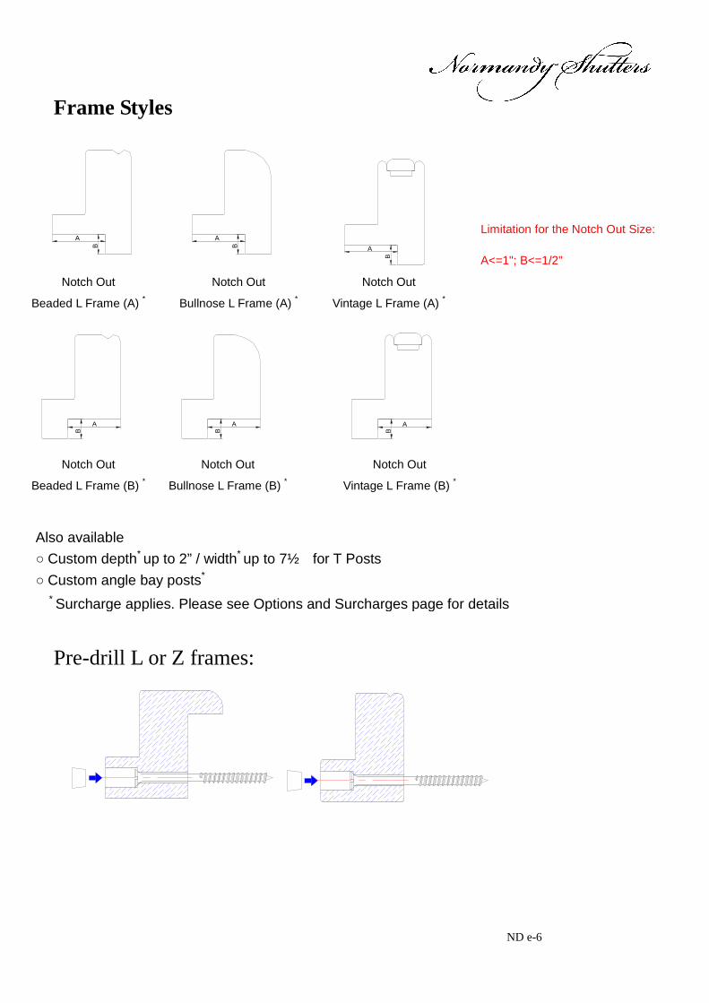
Frame Styles
Pre-drill L or Z frames:
A
B BA
Notch Out
Beaded L Frame (A) *
Notch Out
Bullnose L Frame (A) *
Notch Out
Vintage L Frame (A) *
B
A
A
B B
A
B
A
Notch Out
Beaded L Frame (B) *
Notch Out
Bullnose L Frame (B) *
Notch Out
Vintage L Frame (B) *
Also available
○ Custom depth* up to 2” / width* up to 7½ for T Posts
○ Custom angle bay posts*
○ Light blocks come with 2 sided or 3 sided frames, direct mount and hang strip IM * Surcharge applies. Please see Options and Surcharges page for details
Limitation for the Notch Out Size:
A<=1"; B<=1/2"

Description Minimum Maximum
Single Panel Width (Regular) 6" 42” for 3.5”&4.5” louvers, 36” for other louver type
Single Panel Width (Bifold) 6" 26"
Single Panel Height 10" 133"
Shutter Width (Without T Post) N/A 4x single panel width (bifold) + frame
Shutter Width (With T Post) N/A
Unlimited (For orders shipped by sea, frames longer than 142” will be spliced in the middle. For orders shipped by air, frames longer than 120” will be spliced in the middle.)
Shutter Height N/A 133" + frame
Shutters without bottom supports Normandy shutters will be covered by our warranty for this application, subject to our standard specification limitations and the guidelines listed below:
All Normandy panel configurations:
◊ You must inform Norman Shutters of situations where shutters will not have bottom support when placing the initial order, or warranty will be considered void.
◊ Informing Norman Shutters when placing such orders ensures that the factory will add extra hinges to support the
panel. This will reduce the probability of the panels sagging and increase shutter integrity. ◊ If you fail to notify Norman Shutters that the shutter will be used without a bottom support or used as doors, this
will constitute a misapplication of the shutter. Consequently, you will be responsible for the cost of any RGA Reorder that is submitted.
◊ If you want a bifold shutter, a track must be ordered to support the panels.
General Product Specifications
0831 ND f-1
* For frame and stile exceeding 108", there will be a visible finger joint line in the middle.

* Surcharge applies. Please see Options and Surcharges page for details. NT g-1
1"
Tilt Rods Standard Tilt Rod Default Location: In the middle of the panel on front side (default).
Offset Tilt Rod * Default Location: On the front side of the panel and at 1” from the louver ends on the hinged side. Optional location: per your request
InvisibleTilt™ *
Louver tilting system embedded within panel stile. It is not available for 17/8” louver. The tilting system is split when the number of louvers exceeds the limits as listed below:
For even numbers of louvers, the number of louvers operated by the top and the bottom tilting system will be the same; For odd numbers of louvers, the number of louvers operated by the bottom tilting system will be one more than the number of louvers operated by the top tilting system; To ensure split tilt is included, always specify on the order. Split Tilt When customer requires the split tilt in custom position, the measurement will be as follows, please note that the louvers are in close position when measured. Window size:
— Measure from the bottom of the window to the top of the louver Max frame-to-frame:
— Measure from the bottom of the frame to the top of the louver.
Louver Size Maximum Possible Louvers Panel Height Range
2½" 24 54 3/4” – 57 1/4” 3½" 16 54 3/4” – 58” 4½" 12 54 3/4” – 60”

Divider rail allowable deviations
SU h-1
Divider Rails
• A divider rail is an extra rail in the middle of the panel. • Creates two sections in the panel so louvers can be operated independently. • Strengthens the panel and enhances structural integrity. • Divider rail is required for panel heights over 78”. • 84” panel height limit without divider rail is for Wood French Door Cut Out installed with
button catches & Wood Bypass and bi-fold track shutters. • Custom Size(3”~7.875”) Divider Rail is available with surcharge. Specifications • Standard width: 3” • Default location: center of the panel unless specified otherwise Measurements: • Window size:
— Measure from the bottom of the window to the center of the divider rail. • Max frame-to-frame:
— Measure from the bottom of the frame to the center of the divider rail. • Position:
— Per customer’s specification. However, the divider rail may be adjusted to a lower or higher position, within our allowable deviation, to ensure reinforcement and aesthetics of the shutter. When placing the order, please clearly specify if the divider rail position needs to line up with that of other shutter divider rails in the same room. Please also refer to the table below for the allowable deviation details.
Div
ider
Rai
l Loc
atio
n
Div
ider
Rai
l Loc
atio
n
Win
dow
siz
e he
ight
Max
. fra
me-
to-f
ram
e he
ight
Louver Size Allowable + Deviation 2½" 1" 3½" 1½"
4½" 2"
1215 ND h-1

ND i-1
Hardware
SU i-1
Hinges
* Surcharge applies. Please see Options and Surcharges page for details.
Self-Mortise Hinge
Bi-fold Hinge
L Hinge
Hinges are available in: Pure White, Silk White, Bisque, Pearl, Bright Brass, Antique Brass, Black, Nickel plated, Brushed Nickel Plated and Stainless Steel*

ND i-2
Panel Lock: (not available for 1.625" Stile)
Available Material: All
Color: Brush Nickel-Plated
Position: (Only available on Bottom for Track Shutters with Bottom Track; For Regular, available on Top/Bottom/both Top and Bottom)

ND i-3
Panel Config: FFFFFF(R) The Panel Lock location for both track system shutters and regular shutters would be the same. The general principle is that the Panel Lock position will avoid the stile which will install the spring-loaded guide at bottom (same stile as the Wheel carrier).
Wheel carrierWheel carrierWheel carrierPivotPivot
RR RL L RL Lbolt bolt bolt bolt
Ring pull: for easy opening and closing
(Not available for 1.625" Stile)
32
45
Please note the ring pull finish will match with the hinge finish. Please see the matching chart below:
Hinge Pure White White Bisque Pearl Black Nickel
Brushed Nickel
Oil-Rubbed
Antique Brass
Bright Brass
Stainless Steel
Ring Pull
White White Bisque Pearl Black Brushed Nickel
Brushed Nickel
Black Antique Brass
Bright Brass
Brushed Nickel
Default:
Floating panels stacked to Right

ND i-4
Position: For different panel configuration, please refer to the location of Panel Lock to show on which stile
the pull will be fixed.
Position: A. Above Bottom Rail (Default) B. Above 1st Divider Rail (Default when there are Divider Rails) C. Custom Location If both Panel Lock & ring pull are specified, the distance between them is 2 3/4”, and the ring pull location is 6 3/4” from the bottom of panel. When there is no mid rail, ring pull will be just on the top of Panel Lock (2 3/4” above Panel Lock) as default location; if there are mid rails, bottom of ring pull lines up with top of the 1st mid rail as default location.
Position: A. 2 3/4” Above Panel Lock (Default when both Ring Pull and Panel Lock are specified) B. Above 1st Divider Rail (Default when there are Divider Rails) C. Custom Location

ND i-5
Measurements: • Window size:
— Measure from the bottom of the window to the center of the ring pull. • Max frame-to-frame: — Measure from the bottom of the frame to the center of the ring pull.
Invisible Hinge Frame Options Hinge Notes
2'' Camber Deco Frame Y /
2'' Classic Deco Frame Y /
3" Ridge Deco Frame N /
Vintage L Frame W / 1/4" Light Block N /
Vintage L N /
Vintage L Frame w/ 1/2" Buildout N /
Vintage L Frame w/ 1" Buildout N /
Beaded L w 1/4"light block Y /
Beaded L Y /
Beaded L Frame w/ 1/2" Buildout Y /
Beaded L Frame w/ 1" Buildout Y /
Bullnose L N /
Bullnose L Frame w/ 1/2" Buildout N /
Bullnose L Frame w/ 1" Buildout N /
Tilt out Z Frame N /
1.25" Beaded Z Frame Y /
1.5" Bullnose Z Frame Y /
2" Bel Air Z Frame Y /
3" Crown Z Frame N /
7/8" Vintage Hang Strip (31mm) (27mm for 1" stile)
N /
1" T-Post w/ 1/4" Light Block(for Deco) Y
1" T-Post w/3/4" Light Block(for L/Z/HS) Y
only available with hinge on one side, for example, LTL is available, but RTL is not.
1 3/4" T-Post w/1/4" Light Block(for Deco)
Y available with hinge on BOTH side, for example, RTL.

ND i-6
1 3/4" T-Post w/3/4" Light Block(for L/Z/HS)
Y
Corner Post w/1/4" Light Block(for Deco)
Y /
Corner Post w/3/4" Light Block(for L/Z/HS)
Y /
Bay Post w/1/4" Light Block(for Deco) Y /
Bay Post w/3/4" Light Block(for L/Z/HS) Y /
Invisible Hinge Qty
Panel Height (H) Hinge
Qty
H<=48" 2
48"<H<=78" 3
78"<H<=96" 4
96"<H<=120" 5
H>120" 6
Available Stile:Butt and Astragal
Preinstallation:
Panels and frames will be packaged individually, and the hinge is preinstalled onto the frame/post, with the screws for the other half part on the panels in the hardware box.
If bifold/multi-fold panels are packaged together, the hinges are installed before shipping, or the hinges & screws are packed into the hardware box.

ND i-7
Side Magnet: Available for Butt, rabbet and Astragal stile
Side Magnets will be applied in following situation:
1. Double Hung shutter but without horizontal T post:
Side magnets will be applied to the meeting stiles of the L and R panel. (Default)
2. Café Shutter
Side magnets will be applied to the meeting stiles of the L and R panel. (Default)
3. No frame or light block or L-shape striker plate on either top or bottom, or if larger than standard top or bottom gap is
requested.
Side magnets will be applied to the meeting stiles of the L and R panel. (Optional)

ND j1-1
Bi-fold 180TM
Guidelines and Specs:
Maximum Description Minimum
2½"; 3½" ; 4½"
Single-Panel Width (Bi-fold Track)
6” 26"
Single-Panel Width (LLL/RRR)
6” 20"
Single-Panel Height 10" 133"
Outside Mount Max frame-to-frame width: window width + 3 1/2” Max frame-to-frame height: window height + 4 1/2”
• Track is pre-installed on the header; standard 1 track only.

ND j1-2
Mounting Options: Outside Mount only Side View
76.2 [3"]
38.1
[1 1
/2"]
76.2
[3"]
Win
dow
hei
ght
88.9 [3 1/2"]
38.1
[1 1
/2"]
76.2
[3"]
Win
dow
hei
ght
63.5 [2 1/2"]
88.9 [3 1/2"]
114.3 [4 1/2"]
63.5 [2 1/2"]
88.9 [3 1/2"]
114.3 [4 1/2"]
43.3 [1 11/16"]
30.6 [1 3/16"]
17.9 [11/16"]
30.6 [1 3/16"]
17.9 [11/16"]
5.2 [3/16"]
Dec
o Fa
scia
Flat
Fas
cia
Dec
o Fa
scia
Flat
Fas
cia
85.7
[3 3
/8"]
85.7
[3 3
/8"]
19.1
[3/4
"]
19.1
[3/4
"]
Max
fram
e-to
-fra
me
heig
ht
38.1
[1 1
/2'']
Max
fram
e-to
-fra
me
heig
ht
38.1
[1 1
/2'']
Top View Without Casing:
Note:
◇ Fascia return will protrude the panel about 1/2” for each side. ◇ The header will protrude the panel about 1/8” for each side. ◇ Header, light blocks, and bottom pivot bracket(s) must be installed on a flat surface.

ND j1-3
With Existing Casing:
Hei
ght
MF
F H
eigh
t
MFF width=existing casing width + 114"
58" 5
8"existing casing width
Total width=existing casing width + 114"+1 38"
Dec
o Fa
scia
Flat
Fas
cia
� Header Extension: Optional � Custom extension up to 2” for Header � When extension is needed, the header will protrude the panel 5/16” for
each side and the fascia return will protrude the panel 11/16” for each side.
� The extension will be pre-attached.
Extension
76.2
[3"]
38.1
[1 1
/2"]
3''/3.5''
Dec
o F
asci
a
Fla
t Fas
cia
85.7
[3 3
/8"]

ND j1-4
For 180 Bi-fold, if Bottom Pivot L Bracket is required, the extension for the L shape light block will be 1 3/4” in width. Please see picture below:
Extension

ND j1-5
Panel Configuration ::::Only 2”, 2 1/4” rabbet and butt stiles are availabl e. Center stile is not available.
LLL RRR
LLRR
LL
RR
LLL
RRR
Notes: If there is no baseboard to the wall, 3” header can be used. If there is baseboard to the wall, then it should be as below: 1. If base board thickness is less or equal to 5/8”, 3 1/2” header can be used. 2. If base board thickness is over 5/8”, it is suggest using the 3” header with
build out. And the build out thickness=base board thickness-1/8”.

ND j1-6
Please see the drawing below:
Base board
Thickness
Hei
ght
Dec
o Fa
scia
Flat
Fas
cia
1800 Bi-fold Track Shutters Framing Materials
Type Header Dimension
Top Fascia Dimension
L Shape Light Block Strip Dimension
3” 1 9/16" Header & Top Fascia & Light Block Strip 3 1/2”
3 3/8" 2 1/16"
1800 Bi-fold Track Shutters Hardware Box
Parts
Wrench
Hinge Pin
Support L Bracket (based on the length of header)
2 ½ " screws for support L bracket
¾ " screws for support L bracket
Bottom Pivot Bracket
1 ½ " screws for bottom pivot bracket
2 ½ " screws for Frame with pre-drilled screw holes

ND j1-7
Bi-fold 90 Guidelines and Specs:
Maximum Description Minimum
2½"; 3½" ; 4½"
Single-Panel Width (Bi-fold Track) 6” 26"
Single-Panel Width (Multifold track up to 4 panels)
6” 20"
Single-Panel Height 10" 133"
Outside Mount Max frame-to-frame width: window width + 3 1/2” Max frame-to-frame height: window height + 4 1/2” Semi-Inside Mount Max frame-to-frame width: window width - 1/8” Max frame-to-frame height: window height + 1 3/8” Inside Mount Max frame-to-frame width: window width - 1/8” Max frame-to-frame height: window height - 1/8”
Track is pre-installed on the header; standard 1 track only.

ND j1-8
Mounting Options: Outside Mount
Side View
76[3'']
63[1 1/2'']
89 [3 1/2'']
114 [4 1/2'']
38 [1
1/2
'']
19 [3
/4'']
76[3
'']w
indo
w h
eigh
t
Max
fram
e-to
-fra
me
heig
ht
89[3 1/2'']
63[1 1/2'']
89 [3 1/2'']
114 [4 1/2'']
38.1
[1 1
/2'']
19 [3
/4'']
76[3
'']
Max
fram
e-to
-fra
me
heig
ht
win
dow
hei
ght30.6[1 3/16'']
17.9[11/16'']
5.2[3/16'']
43.3[1 11/16'']
30.6[1 3/16'']
17.9[11/16'']
28 [1
1/8
"]
28 [1
1/8
"]Dec
o Fa
scia
Flat
Fas
cia 38
.1[1
1/2
'']
85.7
[3 3
/8"]
Dec
o Fa
scia
Flat
Fas
cia 38
.1[1
1/2
'']
85.7
[3 3
/8"]
Top View Without Casing:
Note:
◇ Fascia return will protrude the panel about 1/2” for each side.
◇ The header will protrude the panel about 1/8” for each side. ◇ Header, light blocks, and bottom pivot bracket(s) must

ND j1-9
With Existing Casing:
5/8'' 5/8''existing casing width
MF
F H
eigh
t
Dec
o F
asci
a
Fla
t Fas
cia
MFF width=existing casing width + 114"
Total width=existing casing width + 114"+1"
Semi-Inside/Inside Mount
Side View
Semi-inside MountInside Mount
28 [1
1/8
"]
28 [1
1/8
"]
17.9 [11/16"]
5.2 [3/16"]
76.2 [3"]
30.6 [1 3/16"]
63.5 [2 1/2"]
88.9 [3 1/2"]
114.3 [4 1/2"]
19 [3
/4'']
Win
dow
hei
ght
Max
Fra
me
to F
ram
e H
eigh
t
17.9 [11/16"]
5.2 [3/16"]
76.2 [3"]
30.6 [1 3/16"]
63.5 [2 1/2"]
88.9 [3 1/2"]
114.3 [4 1/2"]
Win
dow
hei
ght
Max
Fra
me
to F
ram
e H
eigh
t
Fla
t Fas
cia
Dec
o F
asci
a
Dec
o F
asci
a
Fla
t Fas
cia
85.7
[3 3
/8"]
38.1
[1 1
/2'']
19 [3
/4"]
3.2
[1/8
"]
3.2
[1/8
"]

ND j1-10
Semi-Inside Mount Top View
Window Width
6.35mm [14"]
1.6mm [1/16"]
Overall Panel Width = Window Width -12.7mm[12 "]
MFF Width=Header Width = Window Width -3.2mm[18 "]
1.6mm [1/16"]
6.35mm [14"]
Inside Mount Top View
1.6mm [ 116"]
Window Width
MFF Width=Header Width=Window Width-3.2mm(1/8")
44.4
5mm
[13 4"]
6.35mm [14"]6.35mm [14"]
Overall Panel Width=Window Width-12.7mm(1/2") 1.6mm [ 116"]
44.4
5mm
[13 4"]
� Header Extension: Optional. � Custom extension up to 2” for Header � The extension will be pre-attached.
Extension
76.2
[3"]
38.1
[1 1
/2"]
3''/3.5''
Dec
o Fa
scia
Fla
t Fas
cia
85.7
[3 3
/8"]

ND j1-11
Panel Configuration ::::Only 2”, 2 1/4” rabbet and butt stile are available . Center stile is not available.
LLRR
LL or RR
Optional (Hang Strip for Inside Mount Only)
LL
RR
6.35mm [1/4"]6.35mm [1/4"]
Wheel CarrierPivot
6.35mm [1/4"] 6.35mm [1/4"]
Wheel Carrier Pivot
FF/FF
Wheel Carrier Wheel Carrier Wheel Carrier
LLRR
Pivot Wheel Carrier Pivot
6.35mm [1/4"] 6.35mm [1/4"]
6.35mm [1/4"] 6.35mm [1/4"]
Note: When Butt/rabbet Stile is required, the stile next to the hang strip will be astragal stile.
6.35mm [1/4"]6.35mm [1/4"]
Wheel CarrierPivot
6.35mm [1/4"]6.35mm [1/4"]
Wheel Carrier Pivot
LL
RR

ND j1-12
6.35mm [1/4"] 6.35mm [1/4"]
Pivot Pivot
6.35mm [1/4"] 6.35mm [1/4"]
Wheel Carrier
FF/FF
LLRR
LLL
Wheel Carrier Wheel Carrier Wheel Carrier
900 Multi-Fold Track Shutters (Wood only) Maximum single panel width for multi-fold is 20” Panel Configuration: LLLL, RRRR, or LLLLRRRR
L932" [7mm] 9
32" [7mm] 932" [7mm] 9
32" [7mm] 932" [7mm] 9
32" [7mm] 932" [7mm] 9
32" [7mm]L L L R R R R
Tilt Rods are offset by 7mm(9/32") to the left for left panel and to the right for right panel to enable the shutters to fold completely.
900 Floating Panels
FF FF FF FF
o Two or four panels can be hinged together, fold and slide to either direction
o Application comes with wheel carrier, spring loaded guide and floor track
o Can be used on large window

ND j1-13
Note: 1. For 900 Floating Panels outside mount/semi-inside mount without side boards but with fascia return, the 2016 Stopper will be supplied by default. The gap between the fascia return and the panel is 5mm each side.
The 2016 stopper can also be used in the center or any position of the top track as an option.
2016 Stopper Please see drawing below to show the gap.
2016 Stopper2016 Stopper
5.1mm [3/16"] 5.1mm [3/16"]
2. When rabbet stile required, the meeting stile of unhinged stile will be butt stile by
default. 90 Degree Bi Fold Track Shutters Framing Materials
Type Header Dimension
Top Fascia Dimension
Light Block Strip Dimension
Hang Strip Dimension
3” 1 9/16" OM
3 1/2” 2 1/16" Semi-IM 3"
3 3/8" 5/8"x3/4"
Header & Top Fascia& Light Block
Strip IM 3" 1 7/8" 5/8"x3/4" 1.08”x0.875” Note: It will be L shape light block strip for outside mount.

ND j1-14
Frame Hinged Bifold Available Stile: Rabbet Stile Only Available Frame type
Vintage Hang Strip with 11.5mm light block: For single direction shutter with even panel qty, the frame on the unhinged side will be Vintage Hang Strip with 11.5mm [0.453’’] light block, the height of the Vintage Hang Strip will match with that of the hinged side frame.
22.2mm [0.875"]
Vin
tage
Han
g S
trip
Hei
ght>
46.5
mm
[1.8
3'']
22.2mm [0.875"]
46.5
mm
[1.8
3"]
35m
m [1
.376
"]
11.5
mm
[0.4
53"]
35m
m [1
.376
"]
11.5
mm
[0.4
53"]

ND j1-15
Top View Hinged at Left or Right with wheel assembly at top;
Max Frame to Frame Width
Max Frame to Frame Width
1/16"1/16"
Window Width
Outside Mount
Inside Mount
1 1/2"1 1/2"
Side View
Outside Mount 3-Sides + bottom light block 3-Sides + 3” Deco Sill Frame
25.4
[1"]
3.1
[1/8
"]2.
5 [1
/8"]
Win
dow
Hei
ght
Max
Fra
me
to F
ram
e H
eigh
t
19.1
[3/4
"]
15.9 [5/8"]
Light Block
25.4
[1"]
2.5
[1/8
"]
WS
Hei
ght
F-F
Hei
ght
19.1
[3/4
"]
15.9 [5/8"]
3" Deco Sill Frameat bottom
Light Block
76.2
[3"]

ND j1-16
Semi-Inside Inside Mount
3.2
[1/8
"]
3.1
[1/8
"]2.
5 [1
/8"]
Win
dow
Hei
ght
Max
Fra
me
to F
ram
e H
eigh
t
19.1
[3/4
"]
15.9 [5/8"]
6.3 [1/4"]
3.1
[1/8
"]2.
5 [1
/8"]
Win
dow
Hei
ght
Max
Fra
me
to F
ram
e H
eigh
t
19.1
[3/4
"]
15.9 [5/8"]
6.3 [1/4"]
3.2
[1/8
"]
For frame hinged bifold track shutter used as door, the bottom gap will be 19mm by default. Please specify “Used As Door” on t he order form.
25.4
[1"]
3.1
[1/8
"]19
.1 [3
/4"]
WS
Hei
ght
F-F
Hei
ght
Note: For OM Frame Hinged Bifold shutter not to use as a door, if there is no existing sill at the bottom of the window opening, it is recommended to have the 3” Deco Sill Frame at the bottom.

ND j1-17
Panel Configuration (uneven panel width)
Panel W
idth 1=A
Pan
el W
idth
2=A
+34.
5
Pan
el W
idth
1=A
Panel W
idth 2=A
+34.5
Panel W
idth 1=A
Panel W
idth 1=A Pan
el W
idth
2=A
+34.
5 Panel W
idth 3=A
+34.5
Pan
el W
idth
4=A
+34.
5
Pan
el W
idth
1=A
Panel W
idth 2=A
+34.5
Pan
el W
idth
3=
A+3
4.5P
anel Width 4
=A+34.5
Pan
el W
idth
2=A
+34.
5
Pan
el W
idth
1=A
Panel Width 2=A
+34.5
LL
Vintage Hang Strip at Right (frame height matched with that of the left frame) RR
Vintage Hang Strip at Left (frame height matched with that of the right frame)
LLRR
LLLLRRRR
Panel w
idth 1=A
Pan
el w
idth
2=A
+34
.5m
m Panel w
idth 3=A +34.5m
m
Pan
el w
idth
2=A
+34
.5m
m
LLLL
Pan
el w
idth
1=A
Panel w
idth 2=A +34.5m
m
Pan
el w
idth
3=A
+34
.5m
mPanel w
idth 2=A +34.5m
mRRRR
Vintage Hang Strip at Right (frame height matched with that of the left frame)
Vintage Hang Strip at Left (frame height matched with that of the right frame)

ND j1-18
Notes: 1. Only available for 3-Sides + bottom light block or 3-Sides + 3” Deco Sill
Frame (4-sides is not available); Panels can be folded and open at 90 degree;
90°
2. Frames available: Only Vintage L Frame 1) For top frame, the insert will be replaced by top fascia; 2) Top track will be pre-attached to the top frame; 3) Frame will be pre-drilled with screw holes same as regular shutters. Ring Pull: The ring pull will be provided as an option; and for frame hinged bi-fold, the ring pull will be supplied as default; Customer need specify ring pull location on the order form. Ring pull location is measured from the floor to center of the ring pull in height direction. Ring pull color will match the hinge color. Please refer to below drawing of ring pull position for all shutter types:

ND j1-19
Bottom Pivot Bracket for 90 degree bifold: For 90° Bifold Track Shutter, there will be 2 types of Bottom Pivot Brackets available.
For 180° Bifold Track Shutter, 81mm Bottom Pivot L Bracket will be supplied as default.
For Inside Mount, Bottom Pivot L Bracket will be supplied as default;
For Semi-Inside or Outside Mount, bottom pivot bracket will be supplied as default.

ND j1-20
Track Dimension:
27.4mm
25m
m
Top Track
Extra Magnets will be supplied for Bifold hinges: ( only for the most top and bottom hinges)
Side Magnet: applied to the meeting stiles of LR panels

ND j1-21
Extra magnet and Side Magnet
900 Bi Fold Track Shutters Hardware Box
Parts Wrench Hinge Pin Support L Bracket (based on the length of header) 2 ½ " screws for support L bracket ¾ " screws for support L bracket
Bottom Pivot Bracket 38.1mm screws for bottom pivot bracket 63.5mm screws for Frame with pre-drilled screw holes Notes: 1. for all bifold track shutter Outside Mount, the header will be pre-drilled with
screw holes in the insert and screws will be supplied by default; 2. for all bifold track shutter Inside/Semi-Inside Mount, the header will be pre-
drilled with holes for screws and wood plug and screws and wood plug will be supplied by default

2016 Track Shutters—Bypass
ND j2-1
Guidelines and Specs:
Maximum Description Minimum
2½" 3½" ;;;; 4½"
Single-Panel Width (Wood) 6" 36" 42”
Single-Panel Height 10" 133” 133"
Outside Mount Max frame-to-frame width: window width + 3” Max frame-to-frame height: window height + 4½’’
Semi-Inside Mount Max frame-to-frame width: window width - 1/8” Max frame-to-frame height: window height + 1 3/8”
Inside Mount Max frame-to-frame width: window width - 1/8” Max frame-to-frame height: window height - 1/8”
Carriers are in the Track / Hangers are in the Pane l: Adjustments to panel alignment are made by turning the Carrier Bolt with the wrench included in the Hardware Box

2016 Track Shutters—Bypass
ND j2-2
Top View
38.1mm [1 1/2"]
Outside Mount
Semi-Inside Mount
Inside Mount
Window Width
Max frame-to-frame width
38.1mm [1 1/2"]
Window Width
Max frame-to-frame width
1.6mm[1/8"] 1.6mm[1/8"]
Window Width
Max frame-to-frame width
1.6mm[1/8"] 1.6mm[1/8"]
Size Definition For Semi-Inside/OM without side boards For IM without side boards
Overall Panel WidthFrame to Frame Width = Header Width
5.1mm [0.2"] 5.1mm [0.2"]
2016 Stopper2016 Stopper
Overall Panel WidthFrame to Frame Width = Header Width
1/16" 1/16"
Note: For Semi-Inside/OM bypass without side boards but with fascia return, 2016 Stopper will be supplied.

2016 Track Shutters—Bypass
ND j2-3
Top View Combi - joined Panels (optional)
2''2''
2''
1 5/8''
1 5/8'' 1 5/8''
1 5/8''
Overlap 112"
For shutters with 4 or more panels, please select “side open” or “center open”
Side Open
2''2''
2''
1 5/8''
1 5/8'' 1 5/8''
1 5/8''
Overlap 112"
Center Open
Overlap 112"
2" 2"2"
Overlap 112"
2"2"

2016 Track Shutters—Bypass
ND j2-4
Overlap
Hinge
Hinge
4 panels side open w/Rabbet stile
Overlap Overlap
4 panels center open w/Rabbet stile
HingeHinge
6 panels side open w/Rabbet stile
Overlap
Hinge Hinge
6 panels center open w/Rabbet stile
Hinge HingeOverlap Overlap
Stile: Only 2”, 2 1/4” butt and rabbet stiles are available,
1 5/8” rabbet stile only used for combi-joined panels. Center stile is not available.

2016 Track Shutters—Bypass
ND j2-5
Mounting Options (Closed Bypass) Side View
Outside Mount
1 1/
8"
Bottom Guide
7/8"
1 3/8"
7/8"
3/8"
nylon guide1 1/
2"
Floor
Max
fram
e to
fram
e H
eigh
t
5 1/2"
Support L Bracket
1 1/
2"
Win
dow
ope
ning
hei
ght
4 1/
2"
2 1/2"
3 1/2"
4 1/2"
Dec
o Fa
scia
Flat
Fas
cia
2"4" 4"
Semi-inside Mount Inside Mount
1 1/
8"
1 1/
8"
nylon guide
Bottom GuideBottom Guide
3/8"
1/8"
5/8"
3/8"
1/8"
5/8"
Max
Fra
me
to F
ram
e H
eigh
t
Max
Fra
me
to F
ram
e H
eigh
t
nylon guide
Floor
4 1/2"
1 1/
2"
Win
dow
ope
ning
hei
ght
2 1/2"
3 1/2"
4 1/2"
Dec
o Fa
scia
Flat
Fas
cia
nylon guide
Floor
4 1/2"
Win
dow
ope
ning
hei
ght
2 1/2"
3 1/2"
4 1/2"
Dec
o F
asci
a
Flat
Fas
cia
2" 2"4" 4"1
1/2"
1 1/
2"
2 1/
2"
2 1/
2"
7/8" 7/8"
Bottom Guide

2016 Track Shutters—Bypass
ND j2-6
Mounting Options (Closed Bypass with 3 Tracks):
Support L Bracket
1 1/
2"
2" Wall
Fro
nt
Bac
k
2"7/8"
41 2"
Win
dow
Siz
e
nylon guideFloor
Bottom guide
7 13/16"
3 1/2"
4 1/2"
1 1/4"
3/4"
Max
Fra
me
to F
ram
e S
ize
1 1/
2"
Dec
o F
asci
a
Flat
Fas
cia
4"
4"
Outside Mount
2"
Fro
nt
Bac
k
2"7/8"
Win
dow
Siz
e
nylon guideFloor
Bottom guide
7 13/16"Wall
Max
Fra
me
to F
ram
e S
ize
21 2"
21 2"
Dec
o Fa
scia
Flat
Fas
cia
3 1/2"
4 1/2"
1 1/4"
3/4"
1 1/
2"
Inside Mount
2"
Fro
nt
Bac
k
2"7/8"
1 1/
2"
Win
dow
Siz
e
nylon guideFloor
Bottom guide
7 13/16"
3 1/2"
4 1/2"
1 1/4"
3/4"
Max
Fra
me
to F
ram
e S
ize
Wall
Dec
o F
asci
a
Flat
Fas
cia
4" 4"
Semi-inside Mount
1 1/
2"

2016 Track Shutters—Bypass
ND j2-7
Support L Bracket
1 1/
2"
2" Wall
Fro
nt
Bac
k
2"7/8"
41 2"
Win
dow
Siz
e
nylon guideFloor
Bottom guide
1 7/8"
2 1/2" 3/16"
1/2"
6 1/4"
Max
Fra
me
to F
ram
e S
ize
1 1/
2"
Dec
o F
asci
a
Fla
t Fas
cia
4"
4"
Outside Mount
2"
Fro
nt
Bac
k2"7/8"
nylon guideFloor
Bottom guide
6 1/4"Wall
Max
Fra
me
to F
ram
e S
ize21 2"
21 2"
Dec
o Fa
scia
Flat
Fas
cia
1 7/8"
2 1/2" 3/16"
1 1/
2"
1/2"
Inside Mount
2"
Fro
nt
Bac
k
2"7/8"
1 1/
2"
Win
dow
Siz
e
nylon guideFloor
Bottom guide
1 7/8"
2 1/2" 3/16"
1/2"
6 1/4"
Max
Fra
me
to F
ram
e S
ize
Wall
Dec
o Fa
scia
Flat
Fas
cia
4"
4"
Semi-inside Mount
1 1/
2"
Win
dow
Siz
e

2016 Track Shutters—Bypass
ND j2-8
Mounting Options (Opened Bypass) Only available in 2 ½” and 3 ½” louver sizes 2 ½” Louver
3 9/16"
Floor
1 1/
2"
6 1/4"
2 1/2"2 1/2"
5/8"
Support L Bracket
4"
4 1/
2"W
indo
w S
ize
Max
Fra
me
to F
ram
e S
ize
Dec
o Fa
scia
Fla
t Fas
cia
Outside Mount
7/8"1
1/8"
3 9/16"7/8"
Floor
1 1/
2"
6 1/4"
2 1/2"2 1/2"
5/8"
4" 3 9/16"7/8"
Floor
6 1/4"
2 1/2"2 1/2"
5/8"
Win
dow
Siz
e
Max
Fra
me
to F
ram
e S
ize
Win
dow
Siz
e
2 1/
2"D
eco
Fasc
ia
Flat
Fas
cia
Max
Fra
me
to F
ram
e S
ize
Dec
o Fa
scia
Flat
Fas
cia
Semi-inside Mount Inside Mount
1 1/
8"
1 1/
8"

2016 Track Shutters—Bypass
ND j2-9
3 ½” Louver
4 1/2"7/8"
Floor
3 1/2"3 1/2"
7 13/ 16"
3/4"
Support L Bracket
1 1/
2"
4"D
eco
Fasc
ia
Flat
Fas
cia
4 1/
2"W
indo
w S
ize
Max
Fra
me
to F
ram
e S
ize
Outside Mount
1 1/
8"
4 1/2"7/8"
Floor
3 1/2"3 1/2"
7 13/16"
3/4"
1 1/
2"
4"D
eco
Fas
cia
Fla
t Fas
cia
Max
Fra
me
to F
ram
e S
ize
Wall
4 1/2"7/8"
Floor
3 1/2"3 1/2"
3/4"
Max
Fra
me
to F
ram
e S
ize
Dec
o F
asci
a
Flat
Fas
cia
7 13/16"
Win
dow
Siz
e
Win
dow
Siz
e
Semi-inside Mount Inside Mount
2 1/
2"
1 1/
8"
1 1/
8"

2016 Track Shutters—Bypass
ND j2-10
Open By Pass:has 2 kinds of bottom guide
1 1/
2"
Floor
Dec
o Fa
scia
Fla
t Fas
cia
Floor
Dec
o Fa
scia
Flat
Fas
cia
1 1/
8"
4" 4"
Default Bottom Guide Optional Interlocking Bottom Guide
Opened Bypass Top View
Note: The light block for open bypass will be changed to use screws with wood plugs instead of current dowels.
Separation of track
U shape bottom guide Interlocking bottom guide Louver
Regular Tilt Rod Invisible tilt Regular Tilt Rod Invisible tilt
2.5" 3 9/16" 2 3/4" 3 9/16" 3 9/16"
3.5" 4 1/2" 3 5/8" 4 1/2" 4 1/2"

2016 Track Shutters—Bypass
ND j2-11
Light block thickness for panel U shape bottom guide Interlocking bottom guide
Louver Regular Tilt Rod Invisible tilt Regular Tilt Rod Invisible tilt
h1 3/4" 3/4" 3/4" 3/4" 2.5"
h2 1 9/16" 3/4" 1 9/16" 1 9/16" h1 1 3/16" 1 3/16" 1 3/16" 1 3/16"
3.5" h2 1 15/16" 1 3/16" 1 15/16" 1 15/16"
Nylon Guide: The nylon guide is composed by 2 parts and will supplied as a whole set by default (bottom part 16mm and top part 5mm), please remove the top part if necessary.
The 2016 Stopper For outside mount/semi-inside mount bypass without side boards but with fascia returns, the 2016 Stopper will be supplied by default. The gap between the fascia return and the panel is 5mm each side. The 2016 stopper can also be used in the center or any position of the top track as an option. Please see drawing below to show the gap.
Stopper at sides
5.1mm [3/16"]5.1mm [3/16"]
Stopper at sides Stopper at center or any position

2016 Track Shutters—Bypass
ND j2-12
Note: When the header size is 4½"*, 5½"*, 6¼"* or 713/16"
*, the L Shape header and the U Shape Side Frame will be sent integrally. That is: 1. The header and the supporting strip will be sent integrally as L Shape Header; 2. The side frame, supporting strip and the side fascia will be sent integrally as U Shape Side Frame. For any custom header sizes other than 4½"*, 5½"*, 6¼"* or 713/16"
*, the L Shape Header and the U Shape Side Frame will be sent separately. That is: 1. The header and the supporting strip will be sent separately for L Shape Header; 2. The side frame, supporting strip and the side fascia will be sent separately for U Shape Side Frame.
Framing Size Pc(s)
L Shape Header Header (Closed Bypass) Header (Opened Bypass) Supporting Strip
(2 in 1)
¾" x 5½"* (Default for Outside Mount;
Optional for Semi-Inside and Inside Mount)
¾" x 6¼"* ( 2½" Louver)
¾" x 4½"* (Default for Semi-Inside and Inside
Mount; Optional for Outside Mount)
¾" x 713/16"*
(3½" Louver) Header with Supporting Strip
Custom * < 8" Custom * < 8"
¾" x ¾" 1 pc
U Shape Side Frame Side Frame (Closed Bypass) Side Frame
(Opened Bypass) Supporting
Strip Side
Fascia
(3 in 1)
¾" x 5 7/8"* (Default for Outside Mount;
Optional for Semi-Inside and Inside Mount)
¾" x 6 ⅝"* ( 2½" Louver)
¾" x 4 7/8"* (Default for Semi-Inside and Inside Mount; Optional for Outside Mount)
¾" x 8¼"* (3½" Louver)
Side Frame with Supporting Strip & Side Fascia
Custom * < 8" Custom * < 8"
¾" x ¾" ⅜" x 1¼ "2 pcs
4" (Semi-inside and Outside Mount) Top Fascia
(Plain/Deco) ½" x 2 ½” (Inside Mount)
1 pc
4" (Semi-inside and Outside Mount) Top Fascia Return N/A (Inside Mount)
2 pcs
Track Shutters Framing Materials

2016 Track Shutters—Bypass
ND j2-13
Hardware Box
Hardware Box
Part
Wrench
Nylon Guide
¾ " screws for Nylon Guide
Support L Bracket (based on the length of header)
2 ½ " screws for support L bracket
¾ " screws for support L bracket

ND k-1 * Surcharge applies. Please see Options and Surcharges page for details.
Special Options
Café Shutters *
• The top of the panel requires a special finish. Please indicate “café shutter” when placing orders.
• The shutter does not come with recessed magnet on top.
Max
Fra
me
to F
ram
e
Win
dow
Siz
eWindow Size
Max Frame to Frame
Fixed Louvers Dress Down
Closed (Default) Dress Up Fixed Louvers Dress Down Opened Dress Up
Double -Hung Shutters *
• For total number of panels, please include panels in both rows.
• For panel configuration, please provide panel fold for one row.
• The default location for the division point is the center unless specified otherwise.
● Horizontal T Post* can be added for increased structural integrity.
Fro
nt o
f pan
el
Bac
k of
pan
el
Fro
nt o
f pan
el
Bac
k of
pan
el
Fro
nt o
f pan
el
Bac
k of
pan
el
Fro
nt o
f pan
el
Bac
k of
pan
el
Closed, dressed down
Closed, dressed up
Opened, dressed down
Opened, dressed up

ND k-2 * Surcharge applies. Please see Options and Surcharges page for details.
Special Options
Shutters to be installed in Angled or Horizontal Sk ylight Window Openings
If shutters are going to be installed in angled or horizontal skylight window openings, please specify on the order form.
Available Material Wood Shutters (Not available for Motorized Shutters) Available Frame Type Frame with light block thickness not less than 3/4” Max Panel Size 26” W x 78”H Tilt Rod Invisible Tilt Panel Configuration single panel or single panels with T-Posts Hardware for unhinged side Panel Lock on top and bottom + 2 Button Catches
French Door C ut-out Collection *
• Flush and offset cutout options are available in both curved and square French door cutout. ◊ Offset cutout is good option for French Door with molding around the glass.
• All French door cutouts are only available in L frame except Type E and F. The batten is placed behind the Type E/F panel to block light.
Louver size Batten Width Batten thickness
1 7/8” & 2 1/2” 3/4” 1” 3 1/2” 3/4” 1 3/8” 4 1/2” 3/4” 1 7/8”
• For measurement details please refer to Form section. • French Door cutouts with Arch/Quarter Arch at the top are also available
1/4"thick plywood
1/4"thick plywood
1/4"thick plywood
1/4"thick plywood
Type A Type B Type C Type D
Type E Type F

ND k-3 * Surcharge applies. Please see Options and Surcharges page for details.
Auto Tilt TM (Patented) * • Available in All Shutter Type in Bifold or Multi-fold panel configuration
• Available with Invisible Tilt Only
• Available in 2” Butt, Astragal and Rabbet Stile
• Minimum Louver Qty (Please see below for details)
• Ring pulls included. For ring pull location, please refer to the ring pull section.
• Available in January 2017. When there is only one louver section (no divider rail/no split tilt)
Louver Size Rail Size Minimum Louver qty
2.5" <4.25” 6
>=4.25” 4
3.5" 2.75”~6.5” 4
4.5" 2.75”~6.5” 3
When there is more than one louver sections (with divider rail/ split tilt)
Louver Size Rail Size Minimum Louver qty
2.5" <4.25” 5
>=4.25” 4
3.5" 2.75”~6.5” 3
4.5" 2.75”~6.5” 3
Panel with No divider rail/No split tilt
Panel with divider rail or split tilt

ND k-4 * Surcharge applies. Please see Options and Surcharges page for details.
Standard frame cutouts: R cutout, S cutout, L cutout, C cutout. The sizes can vary. a. R cutout ---Ridge cut out: 0.375”deep x 0.5”wide and 0.375”deep x 1.0” wide (see
below). The cutout can be on the top and the bottom of the frame (available in all styles of the L-frames and all sill plates.)
b. S cutout ---Sill cut out, you are correct it should be 0.375 x 1.25”. (Always on
bottom of bottom frame. Available in all styles of the L-frames and all sill plates.)
c. L cutout ---Lock cutout. There is a possibility of being one or two cutouts on the T-posts depending on the height of the window; For window around 42-48” height, 1 cutout is available; For window around 60” or above, 2 cutouts are available. L cutout can also be needed on single panel windows on the non-hinge side, usually on a style of L-frame. Measuring for L cut out: The default size is 5.125”. Measurements are from the bottom of frame if size type is max frame to frame size and from bottom of window if it is window size to the center of the cut out (2.5625” down and 2.5625” up).
0.375”deep x 0.5”wide
0.375”deep x 1”wide

ND k-5 * Surcharge applies. Please see Options and Surcharges page for details.
d. C cutout---Crank cut outs (C1 cutout, C2 cutout, C3 cutout): (Always on bottom of
bottom frame. Available in all styles of the L-frames and all sill plates.)

ND k-6 * Surcharge applies. Please see Options and Surcharges page for details.
e. A & D cutouts: This should be for the outside mount frames, deco frames, L-
frames. Normally a build out or an extension is used to build the frame out so the frame can set on top of the “keystone”:

ND l-1 * Surcharge applies. Please see Options and Surcharges page for details.
Specialties Specialty Shutters* Specialty shutters are made of premium solid wood, finished to match the beauty of all Norman shutters. Templates are required if it is an imperfect specialty. Delivery time is 8 weeks from the order confirmation date for all specialty shutters. Please refer to Specialties and Template Requirement sections for details.
∗ All frames for specialty shutters will be made as solid frames (not with an insert). However, if there is a regular shutter below a specialty shutter and the frames for both shutters are separated by a divider strip, then the top frame will be made as a solid frame but the bottom frames will be made as regular frames with inserts. If the top frames and the side frames are not separated by a divider strip, both side frames and the bottom frames will be made as solid frames.
Arch Windows Special Shapes
Quarter Round Sunburst Half Round Sunburst Elongated Eyebrow Sunburst Eyebrow Sunburst
Louvered Arch w/ Center Tilt Rod Circle Sunburst
Hexagon Sunburst Triangle
Angle Top Louver Arch in a Rectangle
Angle Top *Top louver of angle top
might be fixed as shown above
Louver Arch in a Rectangle
Arch Top Picture Window with horizontal louvers Arch Top Picture Window with Sunburst
Fixed louver
SU l-1
h
W

ND l-2 * Surcharge applies. Please see Options and Surcharges page for details.
Peak

ND n-2
Appendix Color Coordination Chart
Color ID Color Name Hinge Colour
001 Pure White Pure White
003 Silk White
004 Bright White Silk White
006 Pearl Pearl
009 Creamy
012 Crisp Linen Bisque
030 Moondust Nickel Plated
046 Ice Silk White
108 Rustic Gray Nickel Plated
110 Limed White Silk White
205 Goldenrod
211 Cherry
221 Black Walnut
227 Red Oak
229 Rich Walnut
230 Old Teak
231 Spring Rose
232 Red Mahogany
233 Dark Mahogany
237 Wenge
242 Auburn
249 Acorn
Antique Brass

ND n-2
250 Sumatra
Louver Depth Clearance
Standard Tilt Rod Offset Tilt Rod

ND o 1
New PerfectTilt RF
The new PerfectTilt RF has many exciting features & benefits.
• No need to plug-in, no cords, no hardwiring • Tilt multiple panels in sync or individually • Includes InvisibleTilt™ system, a completely tilt-rod-free solution for a more streamlined view
and improved energy efficiency • Larger solar panels on solar modules absorb more energy than ever before • Ergonomic remote includes 8 preset angles and can control unlimited number of shutters in
range • Utilizes RF signal, not traditional infrared: for precise reception, range up to 65 ft., no sensor
holes, and no need to point remote directly at receiver • Remote is equipped with a timer, allowing you to use your own computer from anywhere at any
time with our proprietary web interface • Whisper quiet, gear-driven system • PerfectTilt® RF wires are concealed inside panel, completely hidden from view • Extra battery packs can be installed as add-on for longer periods between recharges • Ring pulls are required for motorized shutters and must be ordered for warranty to apply.
Parts and Names:

ND o 2
Specifications:
New PerfectTilt RF
Shutter Type All types except bi-fold double hung or panel with gap at bottom over
0.1” (no support on bottom)
Specialty Shutter
Shape
All shapes except shapes without a vertical stile in the middle (for
example, eyebrow, elongated eyebrow, half-round sunburst without
horizontal louvers)
Tilt System InvisibleTilt only, the tilting system will not split unless specified
Stile Width 2.25" stile only
Center Stile is not available
Louver 2.5", 3.5", 4.5" Elliptical louver
Panel Size Limit
Min. Panel Height
(with lined up Motors)
Min. Panel Height
(Default with Staggered Motors)
18”
Louver space not less than 26”, so at
least 13 louvers for 2.5” louver; 9
louvers for 3.5” louver; 7 louvers for 4.5”
louver.
Max. Panel Height without divider rail: 78”
Min. Panel Width Limit: 8 11/16”;
12 5/16” if solar panel is to attach to rail;
Max Width Limit: same as regular non-motorized shutters
Motor Type NS98
Remote Control
*Radio frequency
*6 channels
*8 pre-set angles
*Built-in timer function
*When ordering, customer needs to specify quantity
*Press the “Activation Button” to wake up
Ring Pull
Ring Pull will be supplied as default. (Refer to “i” page for more
information)
Options
Solar Panel/Expansion battery pack=> surcharge option; customer
can choose to add as many Solar Panels/Expansion Battery Packs
as long as space allows

ND o 3
Components:
Items
Remote Control Model : NC85
Radio Frequency; Battery: 2×AAA.
Dimensions : 122 x 62 x 16 mm
Distance of transmission (control): 20 meters
indoor, 40 meters outdoor
Module
Model : NS98
Colors Available: White; Coffee; Caramel
Dimensions : 330.5 x 37.5 x 40 mm
One for each louver section, 6×AA normal
batteries or rechargeable batteries are
required. Either alkaline or lithium batteries
may be used.
Battery cartridge
Make sure the batteries are fit into the
cartridge in correct direction, and when fit the
cartridge into the module, also in right
direction (follow the arrow).
Battery Expansion Pack
Colors Available: White; Coffee; Caramel
Dimensions: 195 x 37 x 21.6 mm

ND o 4
Solar panel
Colors Available: White; Coffee; Caramel
Dimensions: 195 x 37 x 13,5 mm
Position:
A. attached to the module itself (Default)
B. attached to rail (Optional with
surcharge)—For panels with modules
below the mid rail or panels without mid
rail, the solar panel will be attached to the
bottom rail; For panels with modules
above mid rail, the solar panel will be
attached to the top rail.
Mounting base (for Solar panel )
Colors Available: White; Coffee; Caramel
Dimensions: 195 x 37 x 8,5 mm
With Power cable
Colors: Coffee; White
USB Cable
Color: Black
Connect the computer and the remote control
to set up timer function.
Slotted Point Driver
One for each louver section.
Connect the Easy Tilt and the Module; when
fit the slotted point driver into the stile, make
sure the angle is the same as that of the
louvers.
Wood Cover
Battery Cover of the Module

ND o 5
Wood Cover Assembly
(With Battery Cover of the Module
pre-attached with 4 screws, the color of the
wood cover will match that of the shutter
color)
Color Coordinate Chart:
NO. Color
ID Color Name
Module/Battery Expansion
Pack/Solar Panel Color
1 001 Pure White White
2 003 Silk White White
3 004 Bright White White
4 006 Pearl White
5 009 Creamy White
6 012 Crisp Linen White
7 030 Moondust White
8
Paint
8 046 Ice White
1 108 Rustic Grey Coffee
2 110 Limed White White
3 205 Goldenrod Caramel
4 211 Cherry Coffee
5 221 Black Walnut Coffee
6 227 Red Oak Caramel
7 229 Rich Walnut Coffee
8 230 Old Teak Coffee
9 231 Spring Rose Coffee
10 232 Red Mahogany Coffee
11 233 Dark Mahogany Coffee
12 237 Wenge Coffee
13 242 Auburn Caramel
14 249 Acorn Coffee
15
Stain
15 250 Sumatra Coffee

ND o 6
Wood Cover
The battery cover of the module would come with a wood cover that covers at least half section
of the module. And the color of the wood cover will match that of the shutter.
If Expansion Battery Pack or Solar Panel is to fix on the module, please keep the wood cover
and in the future if the expansion battery pack or the solar panel is not needed, the wood cover
can be put back in use.
� Frame Cut-Out
For single panel or configuration similar to single panel with frame, the module location will conflict with
the light block of the frame, so there will be cut-out on the light block of the frame to stop the conflict, the
length for the cut-out would be 335mm
Clearance:
Module Battery Expansion Pack Solar Panel Solar Panel
Mounting Base
Thickness 11/16"(17.5mm) 43/64" (17mm) 23/64"(9mm) 11/32"(8.5mm)
The module will protrude 11/16” from the back of th e stile, please allow 3/4” clearance for the
module.

ND o 7
E.g.: Below is the situation not available for the module unless enough build-out is added to the
frame.
Hang Strip OM: beside the panels
When module is on the left/right most stiles, the protrusion part will conflict with the wall.
L Frame with light block thickness less than 3/4” OM:
When module is on the left/right most stiles, the protrusion part will conflict with the wall.
If both Solar Panel and one Battery Expansion Pack is attached to the module, the necessary
clearance is 1 1/8”;
When more Battery Expansion Packs are needed, pleas e add build-out to allow enough
clearance.
Side view for module in panel with different louver types

ND o 8
For Motorized 90° Bifold Track Shutter:
1) Both 3” and 3.5” Header are available;
2) The L Shape Light Block will be cut out 5/16” to avoid the confliction with the module;
Cut-outCut-out
3''
Cut-out Cut-out
3"
3) For Motorized shutter with both Solar Panel and Expansion Battery Pack attached to the back of
the module, the L Shape Light Block will be cut out 11/16” to avoid the confliction;
Available options:
a. One Solar Panel;
b. One Expansion Battery Pack;
c. One Solar Panel and One Expansion Battery Pack.
4) It is not recommended to have solar panels for the leftmost or rightmost panel due to the lack of
sunlight;

ND o 9
For Motorized 180° Bifold Track Shutter:
1) The default header width is 3.5”; The min. Header width is 3.25”; so for 3” header, 0.25”
extension is required;
2) The L Shape Light Block will be cut out to avoid the confliction with the module; 0.2” extension is
necessary for installation of the top and bottom pivots;
Cut-out
Extension for Top and Bottom Pivots
3.5" 0.2"
3.5"
Cut-out
Extension for Top and Bottom Pivots
0.2"
3) For Motorized shutter with EITHER ONE Solar Panel OR ONE Battery Expansion Pack attached
to the back of the module, the L Shape Light Block will be cut out to avoid the confliction;
Available options:
a. One Solar Panel;
b. One Expansion Battery Pack.
4) It is not recommended to have solar panels for the leftmost or rightmost panel due to the lack of
sunlight.

ND o 10
Module Location: (Easy Tilt will be on the same side as the module)
For regular shutter and bi-fold Application (Except for 2014 bifold track):
1) Single Panel: Module will be on the un-hinge stile
2) 2 Panels: LL, LR, RR
3) 3 Panels: LLL/RRR
4) 4 Panels: LLRR/LLLL/RRRR
For 90° and 180° Bifold Track:
LL/RR
Module
LLRRModule Module

ND o 11
LLL RRRModule Module ModuleModule
LLLL RRRRModule Module Module Module
Special Note on Bi-fold or Multi-fold Configuration s Please be aware that in bi-fold or multi-fold confi gurations of RF, the motorization modules will
touch each other when the panels are folded togethe r, so the panels can’t be able to stack
together as tightly as that of the non-motorized sh utters.
Additionally, before folding the bi-fold or multi-f old panels together, please ensure that the
louvers are returned to a completely closed positio n (either up or down) to prevent louver
damage when folding panels.
For Fold panels, the module installation will be st aggered by default for better fold; it is optional
to line up the modules for bi-fold/multi-fold shutt er;
However, for 180° bifold track shutter, the modules can only be staggered.
Louv
er S
pace
s
Staggered Motors

ND o 12
For By-Pass Application
For Special Shape Application:
Module location will be the same as the Invisible Tilt location.
Built-in Timer Function:
The Timer function is now available for remote unit that were shipped on and after June 1st, 2013.
Please see below for Website link and follow the User Guide to set up the timer schedule for the remote.
Perfect Tilt RF e-Timer website:
www.windowcoveringsautomation.com:9000/
The following is how to distinguish the remote with and without timer function:
Original Remote New Remote w/ Timer
Timer Off Light Color Red Orange
PN Number not available located beneath the back cover
Warranty
The warranty for the Module and the Remote Control Unit is 2-year under normal operation.

ND o 13
SHUTTER LOOK FROM FRONT AND BACK
The front side of the shutter
The back of the shutter
*No Receiver/Louver Cap
*Easy Tilt Only
*The light block would be cut out
along the module.
*The battery cover of the module
would come with a wood cover
And the color of the wood cover
will match that of the shutter.

ND o 14
HOW TO MANUALLY OPERATE THE LOUVERS
At the back of the motor, there is an “M” and “R” which is a remote switch.
HOW TO USE THE EXPANSION BATTERY PACK
Expansion Battery Pack is to provide longer operation time of shutter.
Remove the battery cover and wood cover, and fix the Expansion Battery Pack to the module.
More can be added if the space allows.
*Turn to M to manually operate the
louvers and turn to R to use your
remote to operate the shutter.
Note: Forcing the louvers to rotate
without turning to M will cause
serious damage to your PerfectTilt®
RF system.
*Expansion Battery Pack can be
attached to the module
*Make sure to use same type batteries
in both the module and the Expansion
Battery Pack.

ND o 15
HOW TO USE THE SOLAR PANEL
If Expansion Battery Pack or Solar Panel is to fix on the module, please keep the wood cover
and in the future if the expansion battery pack or the solar panel is not needed, the wood cover
can be put back in use.
* Make sure rechargeable batteries are used in
the module or the Expansion Battery Pack
when using with Solar Panel
*Solar Panel Position:
a. Attached to the back of the module or the
Expansion Battery Pack
b. Installed on the rail (Optional with
surcharge) factory will prewire and install the
mounting base.
For panels with modules below the mid rail or
panels without mid rail, the solar panel will be
attached to the bottom rail;
For panels with modules above mid rail, the
solar panel will be attached to the top rail.

ND o 16
HOW TO FIX LOUVERS THAT ARE OUT OF POSITION
Firstly find out the louver out of position;
Next please grab three louvers above or below the louver in different position.
Then grab the louver out of position and tilt it up/down to put the louver back to the correct
position.
HOW TO REPLACE THE MODULE
*The module can be taken out of the stile when the
louver as well as the slotted point driver is in
horizontal position.
*The customer could also fix the module into the stile
when the louver as well as the slotted point driver is in
horizontal position.

ND o 17
HOW TO REPLACE BATTERY FOR THE MODULE
To install batteries to the open the battery cover. Remove the battery cartridge. Insert batteries
(AA batteries *6) matching the (+) and (-) marks inside the battery cartridge. Put back the
cartridge and reinstall the battery cover.
HOW TO USE THE REMOTE CONTROL
Remote Control Buttons and Indicators
USB Port (Timer Function)
Norman Logo Light:
Light on = Remote Control ready
Light off = Remote Control in sleep mode
8 Preset Louver Positions
Each of the “Angle” keys corresponds to a desired tilting position, spanning the entire arc of
the louver’s movement

ND o 18
Group keys “1” through “5” and “All” key
The keys “1” through “5”control shutter modules grouped in “1” to “5” groups, each group can
consist of unlimited numbers of shutters that are in range.
The “All” key controls shutter modules in all groups at once.
HOW TO REPLACE BATTERY FOR REMOTE CONTROL
The remote control requires 2 AAA batteries. To install the batteries, turn over the remote and
open the cover. Insert batteries (AAA batteries * 2) matching the (+) and (-) marks and cover
the bottom cover. If the battery has been properly installed, the NORMAN® logo will light up.