table of content - elhvb · medium size phillips head screwdriver ... l i e e e 1 3 9 4 c o n t r o...
TRANSCRIPT
1mP4S Version 1.0A
Table of Content
FB11462000000
Quick Installation ....................................................... .3Before Installation........................................................................3Layout...........................................................................................4Item Checklist.......................................................................4Jumpers/ Connectors..................................................................5
Feature ....................................................................... 10Motherboard Components Placement......................................10Block Diagram..............................................................................12Specifications..............................................................................13
Hardware Setup ......................................................... 15Install the Processor...................................................................15Install Memory Modules..............................................................17ATX Power Supply Connector....................................................18Back Panel...................................................................................19

Chapter 1 Quick Installation
2
BIOS Setup ................................................................ 20BIOS Setup.................................................................................20Main Menu...................................................................................22Standard CMOS Features..........................................................22Advanced BIOS Features ...........................................................26Advanced Chipset Features........................................................29Integrated Peripherals...............................................................31Power Management Setup..........................................................36PnP/ PCI Configurations.............................................................40PC Health Status.........................................................................42IWILL Smart Setting....................................................................42Load Fail Safe Defaults..............................................................44Load Optimized Defaults............................................................44Set Supervisor/ User Password Setting....................................45Save & Exit Setup.......................................................................46Exit Without Saving....................................................................46
On board Audio ......................................................... 47Audio Features............................................................................47IWILL 6Channels Audio/SuperAudio(Optional)..........................49Driver Installation.......................................................................51The Audio Rack..........................................................................53

3
Chapter 1 Quick Installation
Quick Installation
Before InstallationFor installation, you may need some or all of the following tools:Medium size flat blade screwdriverMedium size Phillips head screwdriverA 3/16 inch nut driver or wrench
ehterusneotsenilediugesehtwolloftsumsresU.noitallatsnigniruddetcetorpsidraobrehtom
.ffo-derewopsiretupmocruoyerusekaM.1
,tnempiuqecinortcelerehtollaekil,draobrehtomehT.2snoituacerpreporpehtekatesaelP.citatsotevitisnessi
agnihcuotybflesruoydnuorg,elbissopfI.tignildnahnehwevitcudnocstinidraobehtpeek.ksedroelbatlatem
nidellatsniebotydaerdnaderugifnocsitilitnugnipparw.metsysruoy
yppolfdnadrahruoyhtobmorfyawastengamllapeeK.3htobpeeK.srevirdwercscitengamyllaicepse,sevirdksid
.debmessasidfitrapasksiddrahdnayppolf
stidnaretupmocruoymorfyawasdiuqildnaretawpeeK.4.stnenopmoc
Chapter 1 Quick Installation
4
Item Checklist[ V ] The motherboard[ V ] I/O shield[ V ] Operation manual[ V ] ATA 100/66 IDE cable[ V ] Floppy cable[ V ] Power Installer CD[ V ] 6CHG (6 channel audio bracket)[ V ] 6CH1394 (1394 bracket, mP4S-1394 only)
Optional[ ] USB riser kit[ ] IWILL Super Audio (for SPDIF)
Layout
intel
IEE
E 1394C
ontrollor
Eth
erne
tC
ontro
llor
mP4
SmPGA478B

5
Chapter 1 Quick Installation
Jumpers/ConnectorsPS2_SB
Clear CMOS
Flash Protect jumper
Disabled(Default)
Enabled
Clear CMOS
Flashable Protected by H/WControl by BIOS(Default)
Normal(Default)
Ethe
rnet
Con
trollo
r
mPGA478B
Ethe
rnet
Con
trollo
r
mPGA478B
Audio Jumper
LAN Setting
Case Open
Disabled
Disabled
Enabled(Default)
Enabled(Default)
1 2 3
1 2 3
1 2 3
1 2 3
Chapter 1 Quick Installation
6
Ethe
rnet
Con
trollo
r
mPGA478B
CPU Fan
Auxiliary Fan
System Fan
PIN Assignment
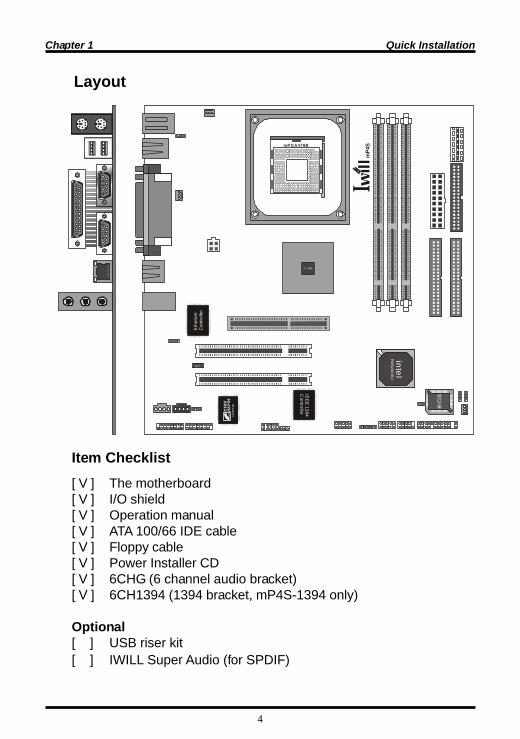
1: GND2: 12V3: Sensor
123
Ethe
rnet
Cont
rollo
r
mPGA478B
Infrared connector (IR)
Internal USB connector
SMBus connectorPIN Assignment1: SMBUSCLK2: NC3: GND4: SMBDATA5: VCC
PIN Assignment
1: 5V 6: NC2: NC 7: CIRRX3: IRRX 8: 5VSB4: GND 9: NC5: IRTX 10: NC
PIN Assignment
1: 5V 6: 5V2: USBDT2- 7: USBDT3-3: USBDT2+ 8: USBDT3+4: GND 9: GND5: GND 10: NC
12345
1
6 7 8 9 10
2 3 4 5
1
6 7 8 9 10
2 3 4 5
7
Chapter 1 Quick Installation
Ethe
rnet
Con
trollo
r
mPGA478B Aux_In/ CD_In Connector
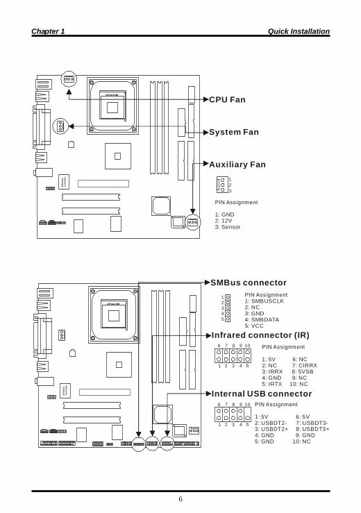
SPDIF & IWILL 6CH bracketPIN Assignment1: +12V 2:NC3: NC 4: SPDIFO 5: SPDIFI 6: GND7: NC 8: SPGPIO9: NC 10: NC11: BASS 12: XREARR13: GND 14: GND15: CENTER 16: XREARL
PIN Assignment1: Left Channel2: GND3: GND4: Right Channel
1 2 3 4
SPDIF 6 CH
1
6
7
8
9
10
11
12
13
14
15
162
3
4
5
Ethe
rnet
Con
trollo
r
mPGA478B
123456
12
3
4
AT-PWR connector
ATX12V connector
PIN Assignment
1: GND 2: GND 3: GND 4: 3.3V 5: 3.3V 6: 5V
PIN Assignment
1: GND 2: GND 3: 12V 4: 12V
Chapter 1 Quick Installation
8
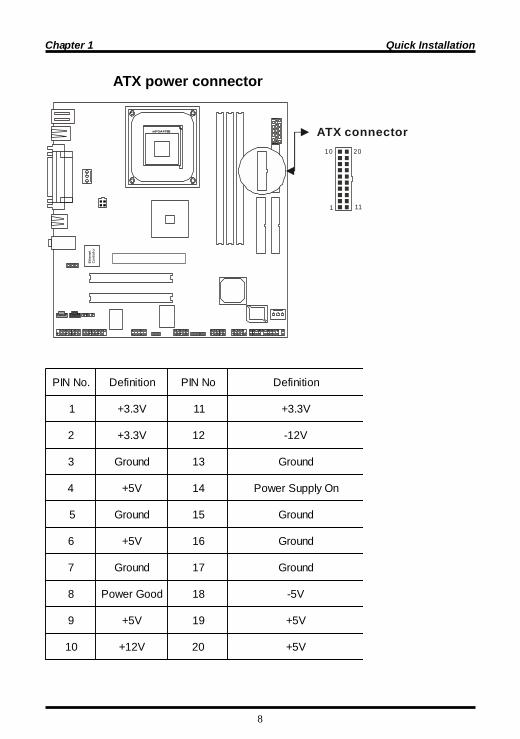
.oNNIP noitinifeD oNNIP noitinifeD
1 V3.3+ 11 V3.3+
2 V3.3+ 21 V21-
3 dnuorG 31 dnuorG
4 V5+ 41 nOylppuSrewoP
5 dnuorG 51 dnuorG
6 V5+ 61 dnuorG
7 dnuorG 71 dnuorG
8 dooGrewoP 81 V5-
9 V5+ 91 V5+
01 V21+ 02 V5+
ATX power connectorEt
hern
etC
ontro
llor
mPGA478B ATX connector
1
10
11
20
9
Chapter 1 Quick Installation
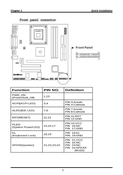
noitcnuF .ONNIP noitinifeDNO_RWP
)ffO_tfoS/rewoP( 31,1
)DELIPCA(IPCA 4,3 edonA:3NIPedohtaC:4NIP
)DELEDI(DELA 8,7 edonA:7NIPedohtaC:8NIP
)TESER(TSR 21,11 TSR:11NIPDNG:21NIP
DELP)DELrewoPmetsyS( 71,61,51
CCV:51NIPCN:61NIP
DNG:71NIP
LK)kcoLdrarobyeK( 91,81 LK:81NIP
DNG:91NIP
)rekaepS(RKPS 42,32,22,12
CCV:12NIPCN:22NIPCN:32NIP
KAEPS:42NIP)ZZUB(
Front panel connectorFront panel connectorFront panel connectorFront panel connectorFront panel connectorEt
hern
etC
ontro
llor
mPGA478B
Front Panel
1
2413
12
10
Chapter2 Feature
Features
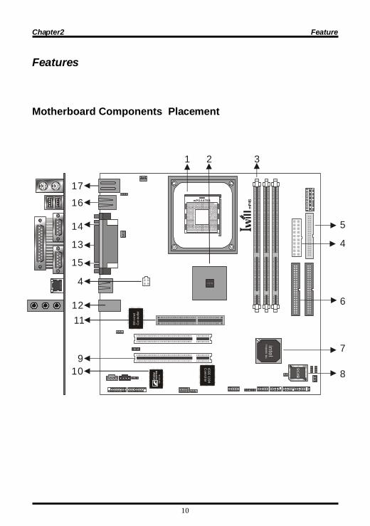
Motherboard Components Placementintel
IEEE 1394
Controllor
Ethe
rnet
Con
trollo
r
mP4
SmPGA478B
1 2 3
4
5
6
7
89
10
1112
13
14
15
1617
4

11
Chapter2 Feature[
.ON noitpircseD
1 )niP874(tekcoSUPC
2 tespihc548i
3 stekcosMMID
4 V21XTA/rewoPTA/rotcennocrewoPXTA
5 rotcennocCDF
6 rotcennocEDI
7 2HCIletnI tespihc
8 HWF SOIBelbammargorproftespihc
9 stolsICP
01 IMC pihcdnuos
11 tolsPGA
21 enohporciM,tuOeniL,nIeniL
31 troPlellaraP
41 1MOC
51 2MOC
61 BSU
71 draobyeK/esuoM2SP
12
Chapter2 Feature
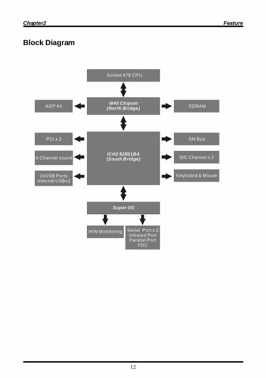
Block Diagram
AGP 4X SDRAM
IDE Channel x 2
Socket 478 CPU
Super I/O
i845 Chipset(North Bridge)
ICH2 82801BA(South Bridge)
PCI x 2
6 Channel sound
H/W Monitoring Serial Port x 2Infrared PortParallel Port
FDC
2xUSB Ports Internal USBx2
Keyboard & Mouse
SM Bus

13
Chapter2 Feature
SpecificationsProcessor / (Socket478)
Supports single processorSupports 400M FSB ( Front Side Bus)Supports Intel Pentium 4 CPU from 1.4 to 2.0 GHz and higher.
CPU Frequency/Voltage Selection
Supports CPU Multiplier selection from BIOSSupports CPU External Frequency selection from BIOS
Memory
Supports PC100/PC133 SDRAMSupports ECC DIMMs(Single bit error Correction, Multiple bit error Detection)Supports 16M/64M/128M/256M/512M DRAM technologySystem memory maximum up to 3GBSupports DIMM type 64Mb/128Mb/256MB
Graphics
Supports AGP 4X 1.5V ONLY
General I/O
PCI 2.1/2.2 complianceSupports 32-bit/33MHz PCI interfaceSupports LPC interfaceSupports ATA33/ATA66/ATA100 IDE interfaceSupports floppy interfaceSupports 16550A UART interfaceSupports ECP/EPP interfaceSupports PS2 interfaceSupports SIR/FIR/CIR interfaceSupports USB interface
Sound support
C-Media 8738 HW Sound controllerSupports 6 ChannelSupports Game/MIDI interfaceSupports Win9X/ WinNT/ Win2000/ Linux/ Net Ware.
14
Chapter2 Feature
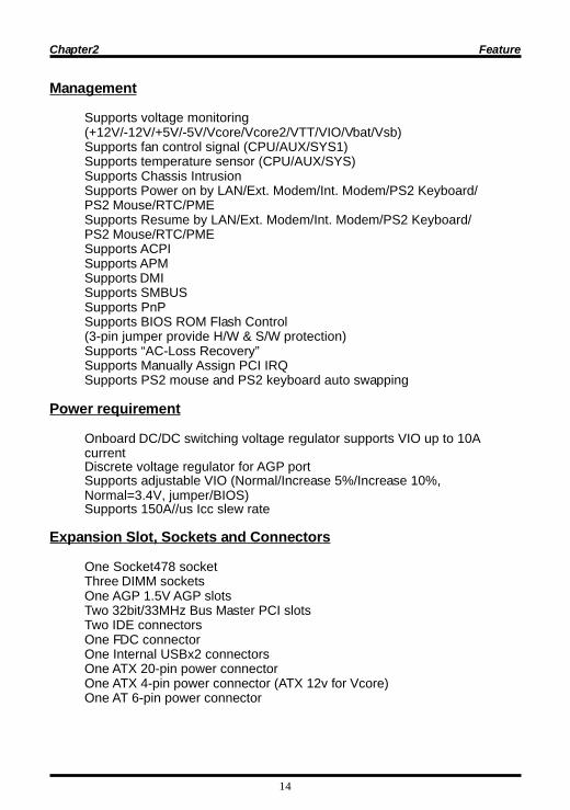
Management
Supports voltage monitoring(+12V/-12V/+5V/-5V/Vcore/Vcore2/VTT/VIO/Vbat/Vsb)Supports fan control signal (CPU/AUX/SYS1)Supports temperature sensor (CPU/AUX/SYS)Supports Chassis IntrusionSupports Power on by LAN/Ext. Modem/Int. Modem/PS2 Keyboard/PS2 Mouse/RTC/PMESupports Resume by LAN/Ext. Modem/Int. Modem/PS2 Keyboard/PS2 Mouse/RTC/PMESupports ACPISupports APMSupports DMISupports SMBUSSupports PnPSupports BIOS ROM Flash Control(3-pin jumper provide H/W & S/W protection)Supports “AC-Loss Recovery”Supports Manually Assign PCI IRQSupports PS2 mouse and PS2 keyboard auto swapping
Power requirement
Onboard DC/DC switching voltage regulator supports VIO up to 10AcurrentDiscrete voltage regulator for AGP portSupports adjustable VIO (Normal/Increase 5%/Increase 10%,Normal=3.4V, jumper/BIOS)Supports 150A//us Icc slew rate
Expansion Slot, Sockets and Connectors
One Socket478 socketThree DIMM socketsOne AGP 1.5V AGP slotsTwo 32bit/33MHz Bus Master PCI slotsTwo IDE connectorsOne FDC connectorOne Internal USBx2 connectorsOne ATX 20-pin power connectorOne ATX 4-pin power connector (ATX 12v for Vcore)One AT 6-pin power connector

15
Chapter 3 Hardware Setup
Intel Pentium 4 Processor Installation ProcedureThe motherboard comes with a surface mount 478-pin ZIF socket.This socket is specifically designed for Intel Pentium 4 478processor.
Hardware Setup
Install the processor retention mechanism following the il lustration.A. Open the socket handle.B. Install the processor by carefully aligning the pins to the socketC. Close the socket handle
Unlock the socket by pressing the lever sideways, then lift it up to avertical angle
Position the CPU above the socketsuch that its marked corner matchesthe base of the socket lever.
Press it firmly on the socket while youpush down the socket lever to securethe CPU.

16
Chapter 3 Hardware Setup
CPU Cooler and heatsink Installation NotesThe Intel Pentium 4 processor requires a specially designed heatsink andfan assembly to ensure optimum thermal condition and performance.
mPGA478B
The heatsink may have thermal interface material attached to the bottom as shown inFig. 1. (Be careful not to damage the thermal interface material.) If not, use the enclosedsyringe and apply all of the thermal interface material to the top of the processor asshown in Fig. 2.
Connection the CPU fan cableWhen the fan, heatsink and the retention mechanism are in place,connect the CPU fan cable to the conner on the fan connector.
Ethe
rnet
Con
trollo
r
mPGA 478B
17
Chapter 3 Hardware Setup
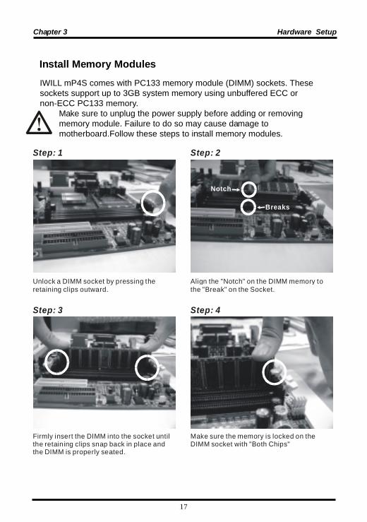
Install Memory ModulesIWILL mP4S comes with PC133 memory module (DIMM) sockets. Thesesockets support up to 3GB system memory using unbuffered ECC ornon-ECC PC133 memory. Make sure to unplug the power supply before adding or removing memory module. Failure to do so may cause damage to motherboard.Follow these steps to install memory modules.
Align the "Notch" on the DIMM memory to the "Break" on the Socket.
Firmly insert the DIMM into the socket until the retaining clips snap back in place and the DIMM is properly seated.
Make sure the memory is locked on the DIMM socket with "Both Chips"
Step: 3 Step: 4
Unlock a DIMM socket by pressing the retaining clips outward.
Step: 1 Step: 2
Notch
Breaks

18
Chapter 3 Hardware Setup
ATX Power Supply Connector
PETS noitpircseD
1 esacmetsysehtesolc,edamerasnoitcennocllaretfA.revo
2 .ffoerasehctiwsllatahteruseB
3 detacolylpppusrewopehtotnidrocrewopehttcennoC.esacmetsysruoyfokcabehtno
4 deppiuqesitahtteltuorewopadrocrewopehttcennoC.rotcetorpegrusahtiw
5aybV022/V011troppusylppusrewopehtfoynaM
tcerrocehtotylppusrewopruoyhctiwS.gnitteshctiws.egatlovylppus
6
redrogniwollofehtnimetsysruoynonruTrotinomehT.a
.secivedlanretxeehT.b.metsysretupmocehT.c
Power on procedures
lliwsissahcehtfolenaptnorfehtnoDELrewopehT-rewopnurnehtlliwmetsyseht,sdnoceswefretfA.thgilehtnoraeppalliwsegassemlanoitiddaemoS.stsetnonihtiwgnihtynaeestonoduoyfI.tsetehtgnirudneercseht,rewopehtnonrutuoyemitehtmorfsdnoces03ehtkcehceR.tsetno-rewopadeliafevahyammetsysrofreliaterruoyllacrosnoitcennocdnasgnittesrepmuj
.ecnatsissa

19
Chapter 3 Hardware Setup
6 Channel, Firewire 1394 and SPDIF Modules6CH1394 6CH audio + Game/Midi port, Firewire ( )mP4S-1394 only
6CH1394
6CHG 6CH audio + Game/Midi port ( )mP4S only
6CHG
SuperAudio 6CH audio + SPDIF ( )Optional
20
Chapter 4 BIOS Setup
BIOS Setup Upgrade BIOS
The BIOS can be upgraded from a diskette with the Award Flashutility — AWDFLASH.EXE. The BIOS image file, and update utilityare available from IWILL’s WEB site: support.iwill.netEnter BIOS setup program
Power-on the system by either pressing the Power-On button, orby using any of the power-on features provided by themotherboard. Then, press the <Del> key after the Power-On SelfTest (POST), and before the scanning of IDE devices. Simply lookfor the message “Press DEL to enter SETUP” displayed at thebottom of the screen during the boot up process. If the messagedisappears before you’ve had a chance to respond, you can restartthe system byturning off the system power then turn it on again,orPressing the “RESET” button on the system case, or
Pressing <Ctrl>, <Alt> and <Del> keys simultaneously.
ylluferacneebevahsgnittestluafedSOIBeht,yllareneGetulosbaehtedivorpsreenignEs'LLIWIybnesohc
yrevsitI.ytilibailerdnaecnamrofrepmumixamlluftuohtiwgnittesynaegnahcotsuoregnad
.uoytahtdnemmocerylgnortseW.gnidnatsrednu.yltcefrepskrowmetsysehtfiSOIBetadpuTONOD
yllufuoysselnugnittesynaegnahcTONOD.snaemtitahwdnatsrednu
BIOS Setup

21
Chapter 4 BIOS Setup
Using BIOS setup program
�Up Move to the previous field�Down Move to the next field�Left Move to the field on the left hand side�Right Move to the field on the right hand side<Esc> Quit from setup program without saving changes,or
Exit from current menu page and return to main menu page
<PgUp> or <+> Select the previous value for a field<PgDn> or <-> Select the next value for a field<F1> General Help<F2> Item Help<F5> Previous Values<F6> Fail-Safe Defaults<F7> Optimized Defaults<F10> Save the current value and exit setup program
If the system is no longer able to boot after changing the settings, theonly way to recover it is to clear the data stored in RTC CMOS. To resetthe RTC CMOS data, take the JP1 jumper cap off pins 1-2, place ontopins 2-3, and then place back onto pins 1-2 again. This will return theRTC to the default setting. Then, get into the BIOS setup program ,choose Load Fail-Safe Defaults ; Load Optimized Defaults, and select theoriginal manufacturer default settings in your CMOS.

22
Chapter 4 BIOS Setup
Main MenuThe main menu allows you to select from several setup pages. Use thearrow keys to select among these pages and press <Enter> key to enterthe sub-menu. A brief description of each highlighted selection appearsat the bottom of the screen.
Stardard CMOS features
CMOS Setup Utility-Copyright(c) 1984-2001 Award Software
Standard CMOS Features
Advanced BIOS Features
Advanced Chipset Features
Integrated Peripherals
Power Management Setup
PnP/PCI Configurations
PC Health Status
ESC: QuitF10: Save & Exit Setup
Time, Date Hard Disk Type...
IWILL Smart Setting
Load Fail-Safe Defaults
Load Optimized Defaults
Set Supervisor Password
Set User Password
Save & Exit Setup
Exit Without Saving
: Select Item
CMOS Setup Utility-Copyright(c) 1984-2001 Award SoftwareStandard CMOS Features
Date (mm:dd:yy)Time (hh:mm:ss)
IDE Primary MasterIDE Primary SlaveIDE Secondary MasterIDE Secondary Slave
Drive ADrive BFloppy 3 Mode Support
VideoHalt On
Base MemoryExtended MemoryTotal Memory
Mon, Jun 18 200115:17:48
[None]None]None]None]
1.44M,3.5i n.][None][Disabled]
EGA/VGA]All Errors]
[[[
[
[[
640k 523264K 524288K
Item Help
Menu Level
Change the day, month,year and century
: Move Enter: Select +/-/PU/PD: Value F10: Save ESC: Exit F1: General Help F5: Previous Values F6: Fail-Safe Defaults F7: Optimized Defaults
23
Chapter 4 BIOS Setup
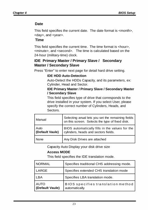
TimeThis field specifies the current time. The time format is <hour>,<minute>, and <second>. The time is calculated based on the24-hour (military-time) clock.IDE Primary Master / Primary Slave / SecondaryMaster / Secondary SlavePress “Enter” to enter next page for detail hard drive setting.
IDE HDD Auto-DetectionAuto-Detect the HDDs Capacity, and its parameters, ex:Cylinder, Head and Sector.IDE Primary Master / Primary Slave / Secondary Master/ Secondary SlaveThis field specifies type of drive that corresponds to thedrive installed in your system. If you select User, pleasespecify the correct number of Cylinders, Heads, andSectors.
launaM sdleifgniniamerehttesuoystellaunagnitceleS.ksiddexiffoepytehtstceleS.neercssihtno
otuA)eluaVtluafeD(
ehtrofseulavehtnisllifyllacitamotuaSOIB.sdleifsrotcesdnasdaeh,srednilyc
enoN dehcattaerasevirDksiDynA
Capacity Auto Display your disk drive sizeAccess MODEThis field specifies the IDE translation mode.
LAMRON .edomgnisserddaSHClanoitidartseificepS
EGRAL edomnoitalsnartSHCdednetxeseificepS
ABL .edomnoitalsnartABLseificepS
OTUA)eluaVtluafeD(
dohtemnoitalsnartseificepsSOIB.yllacitamotua
DateThis field specifies the current date. The date format is <month>,<day>, and <year>.

24
Chapter 4 BIOS Setup
CylindersSet the number of cylinders for this hard disk.HeadsSet the number of read/write headsPrecompSetting a value of 65535 means no hard diskSectorsSet the number of sectors per trackDrive A / Drive BThis field specifies the traditional type of floppy drives.
enoN)tluafedBevirD*( detcennocsievirdyppolFynA
.ni52.5,K063 noitalsnartSHCdednetxeseificepSedom
.ni52.5,M2.1 detcennocsievirdyppolfM2.1A
.ni5.3,K027 .detcennocsievirdyppolfK027A
.ni5.3,M44.1)tluafedAevirD*( detcennocsievirdyppolfM44.1A
.ni5.3,M88.2 detcennocsievirdyppolfM88.2A
Floppy 3 Mode Support
3 Mode floppy drive is a type of 3.5-inch drive used by NEC PC98computers. It supports both 1.2M and 1.44M formats using thesame drive. This field specifies which drive supports 3 Mode.When a floppy drive is specified to support 3 Mode, therespective drive setting in “Drive A / Drive B” field will be invalid.
delbasiD)eulaVtluafeD( ddetcennocsievirdedoM3oN
AevirD AevirdsadetcennocsievirdedoM3A
BevirD BevirdsadetcennocsievirdedoM3A
htoB sevirdedoM3eraBevirddnaAevirdhtoB

25
Chapter 4 BIOS Setup
Video
AGV/AGE)eulaVtluafeD( dretpadaAGVroAGEseificepS
04AGC edomnmuloc04htiwretpadaAGCseificepS
08AGC edomnmuloc08htiwretpadaAGCseificepS
ONOM retpadaemorhconoMseificepS
Halt On
srorrEllA)eulaVtluafeD(
,rorrelataf-nonastcetedSOIBehtemithcaErorrenayalpsiddnapotslliwmetsyseht
egassem
srorrEoN eratahtsrorreynarofpotslliwmetsysehTdetceted
draobyeKtuB,llA tpecxesrorreynarofpotslliwmetsysehTrorredraobyek
etteksiDtuB,llA tpecxesrorreynarofpotslliwmetsysehTrorreetteksid
yeK/ksiDtuB,llA tpecxesrorreynarofpotslliwmetsysehTsrorredraobyekdnaetteksid
Base MemoryThe POST (Power-On Self Test) determines the amount of base(conventional) memory installed in the system. The value of thebase memory is typically 640K. This field has no options.
Extended Memory
The BIOS determines how much extended memory is presentduring the POST. This is the amount of memory located above1MB in the processor’s memory address map. This field has nooptions.Total MemoryDisplays the total memory available in the system
26
Chapter 4 BIOS Setup
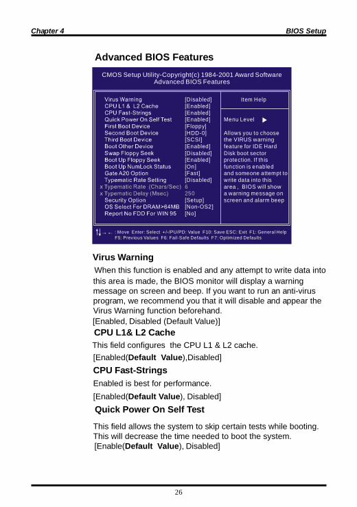
Advanced BIOS Features
This field configures the CPU L1 & L2 cache.
When this function is enabled and any attempt to write data intothis area is made, the BIOS monitor will display a warningmessage on screen and beep. If you want to run an anti-virusprogram, we recommend you that it will disable and appear theVirus Warning function beforehand.
CMOS Setup Utility-Copyright(c) 1984-2001 Award SoftwareAdvanced BIOS Features
[Disabled][Enabled][Enabled][Enabled][Floppy][HDD-0][SCSI][Enabled]
[Enabled][On][Fast][Disabled]
[Setup][Non-OS2][No]
[Disabled]
6250
Item Help
Menu Level
Allows you to choosethe VIRUS warningfeature for IDE HardDisk boot sector protection. If this function is enabled and someone attempt towrite data into this area , BIOS will show a warning message onscreen and alarm beep
: Move Enter: Select +/-/PU/PD: Value F10: Save ESC: Exit F1: General Help F5: Previous Values F6: Fail-Safe Defaults F7: Optimized Defaults
[Enabled, Disabled (Default Value)]
[Enabled(Default Value),Disabled]CPU Fast-StringsEnabled is best for performance.[Enabled(Default Value), Disabled]
Quick Power On Self Test
This field allows the system to skip certain tests while booting.This will decrease the time needed to boot the system.
[Enable(Default Value), Disabled]
CPU L1& L2 Cache
Virus Warning

27
Chapter 4 BIOS Setup
First / Secondary / Third / Boot Other Device
The BIOS attempts to load the operating system from the devicesin the sequence selected in these items.[Floppy, LS120, HDD-0, SCSI, CDROM, HDD-1, HDD-2,HDD-3, ZIP100, LAN, Disabled]Swap Floppy DriveWhen enabled, floppy drives A and B will be exchanged withoutthe user physically changing the connection on the cable.[Enable, Disabled(Default Value)]Boot Up Floppy SeekSeeks disk drives during boot up. Disabling speeds boot up.[Enabled, Disabled (Default Value)]
Boot Up NumLock Status
[ON(Default Value),Off]Gate A20 OptionThis field configures how the gate A20 is handled. The gate A20 isa device used to address memory above 1 MB. At first, the gateA20 was handled from a pin on the keyboard. While somekeyboards still provide this support, it is more common, and muchfaster, for modern system chipsets to provide support for gate A20.[Fast(Default Vaule):GateA20 signal supported by core logic][Normal: GateA20 signal supported by keyboard controller].Typematic Rate SettingThis field determines if the typematic rate is to be used. Whenenabled, the BIOS will report (after a moment) that the key hasbeen depressed repeatedly. When disabled, the BIOS will reportonly once if a key is held down continuously. This feature is usedto accelerate cursor movements using the arrow keys.[Enable, Disabled(Default Value)]
This field determines the configuration of the numeric keypad aftersystem boot up. If On, the keypad uses numbers keys. If Off,thekeypad uses arrow keys.
28
Chapter 4 BIOS Setup
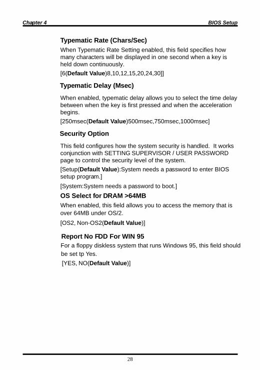
Typematic Rate (Chars/Sec)When Typematic Rate Setting enabled, this field specifies howmany characters will be displayed in one second when a key isheld down continuously.[6(Default Value)8,10,12,15,20,24,30]]
Typematic Delay (Msec)
When enabled, typematic delay allows you to select the time delaybetween when the key is first pressed and when the accelerationbegins.[250msec(Default Value)500msec,750msec,1000msec]
Security Option
This field configures how the system security is handled. It worksconjunction with SETTING SUPERVISOR / USER PASSWORDpage to control the security level of the system.[Setup(Default Value):System needs a password to enter BIOSsetup program.][System:System needs a password to boot.]OS Select for DRAM >64MBWhen enabled, this field allows you to access the memory that isover 64MB under OS/2.[OS2, Non-OS2(Default Value)]
Report No FDD For WIN 95
[YES, NO(Default Value)]
For a floppy diskless system that runs Windows 95, this field shouldbe set tp Yes.
29
Chapter 4 BIOS Setup
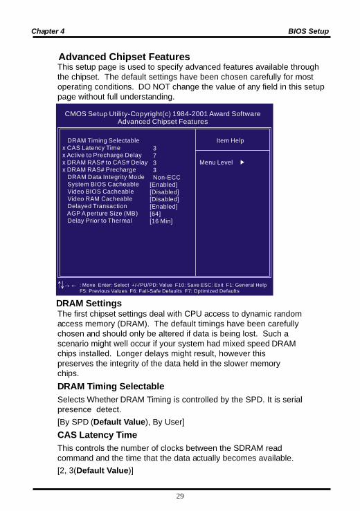
This setup page is used to specify advanced features available throughthe chipset. The default settings have been chosen carefully for mostoperating conditions. DO NOT change the value of any field in this setuppage without full understanding.
The first chipset settings deal with CPU access to dynamic randomaccess memory (DRAM). The default timings have been carefullychosen and should only be altered if data is being lost. Such ascenario might well occur if your system had mixed speed DRAMchips installed. Longer delays might result, however thispreserves the integrity of the data held in the slower memorychips.DRAM Timing SelectableSelects Whether DRAM Timing is controlled by the SPD. It is serialpresence detect.[By SPD (Default Value), By User]CAS Latency TimeThis controls the number of clocks between the SDRAM readcommand and the time that the data actually becomes available.[2, 3(Default Value)]
CMOS Setup Utility-Copyright(c) 1984-2001 Award SoftwareAdvanced Chipset Features
DRAM Timing Selectablex CAS Latency Timex Active to Precharge Delayx DRAM RAS# to CAS# Delayx DRAM RAS# Precharge
DRAM Data Integrity Mode System BIOS Cacheable Video BIOS Cacheable Video RAM Cacheable Delayed Transaction AGP A perture Size (MB) Delay Prior to Thermal
3 7 3 3 Non-ECC[Enabled][Disabled][Disabled][Enabled][64][16 Min]
Item Help
Menu Level
: Move Enter: Select +/-/PU/PD: Value F10: Save ESC: Exit F1: General Help F5: Previous Values F6: Fail-Safe Defaults F7: Optimized Defaults
DRAM Settings
Advanced Chipset Features
30
Chapter 4 BIOS Setup
Delayed Transaction
When enabled, the south bridge ICH2 will supports the DelayedTransaction mechanism when it is the target of a PCI transaction.[Enable(Default Value),Disabled]AGP Aperture Size (MB)This field configures the main memory size for AGP graphics dataused.[4MB, 8MB, 16MB, 32MB,64MB(Default Value), 128MB, 256MB]
DRAM RAS# PrechargeIf an insufficient number of cycles is allowed for the RAS toaccumulate its charge before DRAM refresh, the refresh may beincomplete and the DRAM may fail to retain data. This controls theidle(delay) clocks after issueing a prechange command to theSDRAM.[2,3(Default Value)]System BIOS CacheableWhen enabled, accesses to the system BIOS will be cached.[Enable(Default Value),Disabled]Video BIOS CacheableWhen enabled, access to the video BIOS will be cached.[Enable, Disabled(Default Value)]Video RAM CacheableWhen Disabled, access to the video memory located at A0000H toBFFFFH will be cached.[Enabled, Disabled (Default Value)]
DRAM RAS# to CAS# DelayThis controls the number of clocks between the SDRAM activecommand and the read / write command.[2,3(Default Value)]

31
Chapter 4 BIOS Setup
Integrated PeripheralsCMOS Setup Utility-Copyright(c) 1984-2001 Award Software
Integrated Peripherals
On-Chip Primary PCI IDE On-Chip Secondary PCI IDE IDE Primary Master PIO IDE Primary S lave PIO IDE Secondary Master PIO IDE Secondary Slave PIO IDE Primary Master UDMA IDE Primary S lave UDMA IDE Secondary Master UDMA IDE Secondary Slave UDMA USBController USB Keyboard Support Init Display First IDE HDD Block Mode POWER ON Functionx kB Power ON Passwordx Hot Key Power ON Onboard FDC Controller Onboard Seria l Port 1 Onboard Seria l Port 2 UART Mode Selectx RxD , TxD Activex IR Transmission Delayx UR2 Duplex Modex Use IR Pins Onboard Parallel Port Parallel Port Modex EPP Mode Selectx ECP Mode Use DMA PWRON After PWR-Fail SCR Port Addressx SCR Port IRQ
[Enabled][Enabled][Auto][Auto][Auto][Auto][Auto][Auto][Auto][Auto][Disabled][Disabled][AGP][Enabled][BUTTON ONLY]EnterCtrl-F1[Enabled][3F8/IRQ4][2F8/IRQ3]Normal]Hi , LoEnabledHalfIR-Rx2Tx2[378/IRQ7][SPP]EPP1.93[Off][Disabled]11
Item Help
Menu Level
: Move Enter: Select +/-/PU/PD: Value F10: Save ESC: Exit F1: General Help F5: Previous Values F6: Fail-Safe Defaults F7: Optimized Defaults
32
Chapter 4 BIOS Setup
otuA )eulaVtluafeD(0edoM1edoM2edoM3edoM4edoM
yllacitamotuaecivedhtiwdetaitogeNecivedsseccaotgnimit0edoMesUecivedsseccaotgnimit1edoMesUecivedsseccaotgnimit2edoMesUecivedsseccaotgnimit3edoMesUecivedsseccaotgnimit4edoMesU
IDE Primary Master / Slave UDMAIDE Secondary Master / Slave UDMA
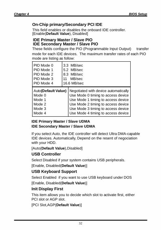
If you select Auto, the IDE controller will detect Ultra DMA-capableIDE devices. Automatically, Depend on the resent of negociationwith your HDD.[Auto(Default Value),Disabled]USB ControllerSelect Disabled if your system contains USB peripherals.[Enable, Disabled(Default Value)]USB Keyboard SupportSelect Enabled if you want to use USB keyboard under DOS[Enable, Disabled(Default Value)]Init Display FirstThis item allows you to decide which slot to activate first, eitherPCI slot or AGP slot.[PCI Slot,AGP(Default Value)]
0edoMOIP1edoMOIP2edoMOIP3edoMOIP4edoMOIP
ces/BM3.3ces/BM2.5ces/BM3.8ces/BM11ces/BM6.61
IDE Primary Master / Slave PIO IDE Secondary Master / Slave PIO
These fields configure the PIO (Programmable Input Output) transfermode for each IDE devices. The maximum transfer rates of each PIOmode are listing as follow:
This field enables or disables the onboard IDE controller.[Enable(Default Value), Disabled]
On-Chip primary/Secondary PCI IDE

33
Chapter 4 BIOS Setup
The Power-On button will not function in this mode.
drowssaP gnirtsdrowssapangissanacuoY.dleifdrowssaPnO-rewoPBKhguorht
YEKtoH yeKtoHehthguorhtyektohangissanacuoY-rewoplliwyektohsihtgnisserP.dleifnO-rewoP
.metsysruoyno
/esuoMdrowssaP
BKehtgnipytronottubesuomehtgnikcilC-elbuoDno-rewopyllacitamotualliwdrowssapno-rewop
mertsysruoy
YEKtoH/esuoM BKehtgnipytronottubesuomehtgnikcilC-elbuoDmertsysruoyno-rewoplliwyek-toh
YLNONOTTUB)eulaVtluafeD(
ehtgnisserpybmetsysruoyno-rewopylpmiSCPruoyfolenaptnorfehtnonottubnO-rewoP
esac
89draobyeK sinoitcnuofsihT.noitcnuf89draobyeKselbanE.89draobyeKfosresurofylnodoog
KB Power ON PasswordIf you wish to use this function, bring the cursor to thefield written Enter, then press <Enter>. The computer willdisplay the message, Enter Password”. Type yourpassword and press <Enter>. After the message ConfirmPassword is displayed, re-type your password. The KBPower-On function will be in effect after you save and exitsetup.To disable a password, bring the cursor to the Enter” fieldagain, then press <Enter>. The computer will display themessage, Enter Password Press <Enter>. A message willconfirm that the password is disabled.
Power-On FunctionThis field configures the Power-On mode of the system.
IDE HDD Block ModeWhen enabled, the IDE controller will use the faster block mode toaccess devices.[Enable(Default Value), Disabled]

34
Chapter 4 BIOS Setup
This field enables or disables the onboard floppy controller.[Enable(Default Value),Disabled]
Onboard Serial Port 1 / 2These fields configure the onboard serial ports. There are severalport addresses and IRQ channels to select from.
UART Mode Select
When setting the field to either IrDA or ASKIR, you mustselect the active level of receiving and transmission signal.[Hi,Lo(Default Value)/Lo,Hi/Lo,Lo/Hi,Hi]
IR Transmission delay for IrDA and ASKIR functions
4QRI/8F3)eluaVtluafeD(
4QRI,h8F3sserddatroP
3QRI/8F2)eluaVtluafeD(
3QRI,h8F2sserddatroP
4QRI/8E3 4QRI,h8E3sserddatroP
3QRI/8E2 3QRI,h8E2sserddatroP
otuA QRIdnasserddatropsngissaSOIB.yllacitamotualennahc
.delbasiD troplairesselbasiD
[IrDA, ASKIR, Normal(Default Value)]
When setting the field to either IrDA or ASKIR, you must selectwhether or not you require a delay between IR transmissions.
Hot Key Power-On This field specifies key selection for the Keyboard-Power
On hot key. [Ctrl-F1,Ctrl-F2,Ctrl-F3,Ctrl-F4,Ctrl-F5,Ctrl-F6,Ctrl-F7,Ctrl-
F8,Ctrl-F9, Ctrl-F10,Ctrl-F11,Ctrl-F12]
Onboard FDC Controller
RxD, TxD Active for IrDA and ASKIR functions
[Enabledl(Default Value), Disabled]
35
Chapter 4 BIOS Setup
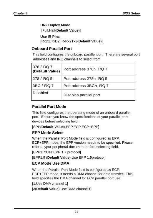
Onboard Parallel Port This field configures the onboard parallel port. There are several port addresses and IRQ channels to select from.
7QRI/873)eulaVtluafeD( 7QRI,h873sserddatroP
5QRI/872 5QRI,h872sserddatroP
7QRI/CB3 7QRI,hCB3sserddatroP
delbasiD troplellarapselbasiD
Parallel Port ModeThis field configures the operating mode of an onboard parallelport. Ensure you know the specifications of your parallel portdevices before selecting field.[SPP(Default Value),EPP,ECP ECP+EPP]
EPP Mode SelectWhen the Parallel Port Mode field is configured as EPP,ECP+EPP mode, the EPP version needs to be specified. Pleaserefer to ypur peripheral document before selecting field.[EPP1.7:Use EPP 1.7 protocol][EPP1.9 (Default Value):Use EPP 1.9protocol]ECP Mode Use DMAWhen the Parallel Port Mode field is configured as ECP,ECP+EPP mode, it needs a DMA channel for data transfer. Thisfield specifies the DMA channel for ECP parallel port use.[1:Use DMA channel 1][3(Default Value):Use DMA channel1]
UR2 Duplex Mode [Full,Half(Default Value)]
Use IR Pins [RxD2,TxD2,IR-Rx2Tx2(Default Value)]

36
Chapter 4 BIOS Setup
This feature allows the user to select the default parameters forthe power-saving mode.
gnivasniM metsyseht,ruohenorofeldinehW.edomdnepsusretne
gnivaSxaM metsyseht,setunimneetfifrofeldinehW.edomdnepsussretne
enifeDresU)eluaVtluafeD(
metsysehtemitehtyficepsnacresU.edomdnepsussretne
Each power-saving mode has a respective timer. The value of the timer can be assigned or reloaded and it will count down tozero. When the timer equals to zero, the system will be forcedinto the related suspend or power-saving mode. If any predefinedsignal or event is detected during the timer counting period, thetimer restarts automatically.
Power Management SetupCMOS Setup Utility-Copyright(c) 1984-2001 Award Software
Power Management Setup Power Management Video Off Method Video Off In Suspend Suspend Type MODEM Use IRQ APM Suspend Timer APM HDD Power Down Timer PWR-OFF Mode by PWR-BTTN Wake Up by PCI card Wake Up by Ring/LAN CPU THRM-Throttling PWROn/Resume by Alarm x x
**Reset APM Timer Events** Primary IDE 0
Date (of Month) AlarmTime (hh:mm:ss) Alarm
Primary IDE 1 Secondary IDE 0 Secondary IDE 1 FDD, COM, LPT Port PCI IRQ#
[User Define][V /H SYNC+Blank][Yes][Stop Grant][3 ][Disabled][Disabled][Instant-Off][Disabled][Disabled][62.5% ][Disabled]00 :0 : 0
[Disabled][Disabled][Disabled][Disabled][Disabled][Disabled]
Item Help
Menu Level
: Move Enter: Select +/-/PU/PD: Value F10: Save ESC: Exit F1: General Help F5: Previous Values F6: Fail-Safe Defaults F7: Optimized Defaults
Power Management

37
Chapter 4 BIOS Setup
Video off Method
knalB+CNYSH/V)eluaVtluafeD(
latnozirohdnalacitrevehtffonruTsknalbetirwdnastropnoitazinorhcnys
.reffuboedivehtot
neercSknalB .ylnoreffuboedivehtotsknalbsetirW
SMPD tnemeganamrewopyalpsidlaitinI.SMPDhtiwgnilangis
This determines the manner in which the monitor is blanked.[NO,Yes(Default Value)]Suspend TypeSelect the Suspend Type.[PwrOn Suspend, Stop Grant (Default Value)]
MODEM Use IRQ
This field specifies the time the system enters power-saving mode.It is available only when the Power Management field is set toUser Define.[1Min, 2Min, 4Min, 8Min, 12Min, 20Min, 30Min, 40Min, 1Hour,Disabled(Default Value)]APM HDD Power Down TimerThis field specifies the time the system enters HDD power down.It is available only when the Power Management field is set toUser Define.[1Min, 2Min, 3Min, 4Min, 5Min, 6Min, 7Min, 8Min, 9Min,10Min,11Min, 12Min, 13Min, 14Min, 15Min, Disabled(Default Value)]
This field specifies the function of power button.
seconds, the system turns off.]
PWR-Off Mode by PWR-BTTN
[Instant-Off(Default Value):When power button pressed, the system turns off immediately.][Delav 4 Sec: After the power button has been pressed andheld for four
This determines the IRQ in which the MODEM can use.[3(Default Value),4,5,7,9,10,11,NA]
APM Suspend Timer
Video Off In Suspend

38
Chapter 4 BIOS Setup
Wake up by PCI card [Enabled, Disabled(Default Value)]
Wake up by RING/LAN When Wake up by LAN function is enabled, the PC can power-on
or “wake up” through LAN (Local Area Network). When Wake upby RING function is enabled, the PC can power-on through anexternal modem connected to your PC.
%5.78 ecnamrofrepdeepsllufsUPCfo%5.78peeK
%0.57 ecnamrofrepdeepsllufsUPCfo%0.57peeK
%5.26)eluaVtluafeD( ecnamrofrepdeepsllufsUPCfo%5.26peeK
%0.05 ecnamrofrepdeepsllufsUPCfo%0.05peeK
%5.73 ecnamrofrepdeepsllufsUPCfo%5.73peeK
%0.52 ecnamrofrepdeepsllufsUPCfo%0.52peeK
%5.21 ecnamrofrepdeepsllufsUPCfo%5.21peeK
CPU THRM-Throttling [Enabled, Disabled(Default Value)]
When enabled, you can set the date and time to automaticallypower-on your PC (similar to an alarm clock).
delbanE ,nim,rh(remiTdna)13-0(etaDsteSsietadnehW.CPehtno-rewopot)ces.yadyreveroftessiremiTeht,0ottes
delbasiD)eluaVtluafeD(
noitcnufmralaCTRselbasiD v
PWROn/Resume by Alarm
Reset APM Timer EventsThis field enables the system to detect activity, and restart thetimer of the power-saving mode. Primary IDE 0
If enabled, timer restarts whenever the master disk of theprimary IDE channel is active.[Enabled, Disabled (Default Value)]
39
Chapter 4 BIOS Setup
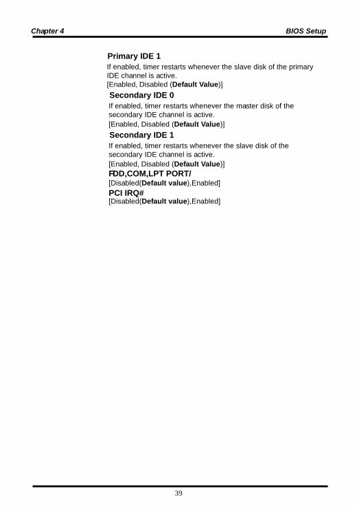
Secondary IDE 0If enabled, timer restarts whenever the master disk of thesecondary IDE channel is active.[Enabled, Disabled (Default Value)]
Secondary IDE 1If enabled, timer restarts whenever the slave disk of thesecondary IDE channel is active.[Enabled, Disabled (Default Value)]FDD,COM,LPT PORT/[Disabled(Default value),Enabled]PCI IRQ#[Disabled(Default value),Enabled]
Primary IDE 1If enabled, timer restarts whenever the slave disk of the primaryIDE channel is active.[Enabled, Disabled (Default Value)]

40
Chapter 4 BIOS Setup
The field specifies whether a Plug and Play operating system isinstalled.[Yes,No(Default Value)]Reset Configuration DataNormally, you leave this field Disabled. Select Enabled to resetExtended System Configuration Data (ESCD) when you exit Setupif you have installed a new add-on and the system reconfigurationhas caused such a serious conflict that the operating system cannot boot.[Enabled, Disabled(Default Value)]
CMOS Setup Utility-Copyright(c) 1984-2001 Award SoftwarePnP/PCI Configurations
[No][Disabled]
[Auto (ESCD)]Press Enter Press Enter
[Disabled]
Item Help
Menu Level
Select Yes if you are using a Plug and Playcapable operationsystem Select No if you need the BIOS toconfigure non-boot devices
: Move Enter: Select +/-/PU/PD: Value F10: Save ESC: Exit F1: General Help F5: Previous Values F6: Fail-Safe Defaults F7: Optimized Defaults
PNP OS InstalledReset Configuration Data
Resources Controlled Byx IRQ Resourcesx Memory Resources
PCI/VGA Palette Snoop
PnP/ PCI Configurations
PNP OS Installed

41
Chapter 4 BIOS Setup
IRQ Resources When resoruces are controlled manually, assign each system interrupt a type, depending on the type of device using the interrupt. IRQ3/4/5/7/9/10/11/12/14/15 assigned to [PCI/ISA PnP (Default Value), Legacy ISA] DMA Resources This sub menu can let you control the memory resource.
Reserved Memory Base Reserved a low memory for the legacy device (non-PnP device). [C800,CC00,D000,D400,D800,DC00,N/A(Default Value)] Reserved Memory Length Reserved a low memory length for the legacy device (non-PnP device). [8K(Default Value),16K,32K,64K]
Resources Controlled ByThe Award Plug and Play BIOS has the capacity to automaticallyconfigure all of the boot and Plug and Play compatible devices.However, this capability means absolutely nothing unless you areusing a Plug and Play operating system such as Windows98/95/NT. If you set this field to “manual” choose specific resources bygoing into each of the sub menu that follows this field (a sub menuis preceded by a “Ø”).[Manual: Resources controlled by the user.Auto(ESCD)(Default Vaule): Resources controlled by BIOSautomatically]
PCI / VGA Palette Snoop
This field controls the ability of a primary PCI graphics controller toshare a common palette with an ISA/VESA video or MPEG card.
delbanE dracGEPMASIhtiwskrow-ocAGVICP
delbasiD)eluaVtluafeD( .evobatpecxesesacllA
42
Chapter 4 BIOS Setup
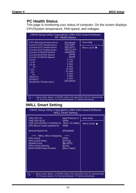
PC Health Status
CMOS Setup Utility-Copyright(c) 1984-2001 Award SoftwarePC Health Status
Item Help
Menu Level
CPU Warning TemperatureCurren t CPU TemperatureCurren t SYS TemperatureCurren t SYS TemperatureCurren t CPUFAN SpeedCurren t AUXFAN SpeedCurren t SYSFAN SpeedVcore.+1.8v+3.3v+ 5v+12v -12v - 5vVBAT(V)5VSB(V)Shutdown Temperatu re
[Disabled]21 C/69 F28 C/82 F45 C/113 F4500RPM 0RPM 0RPM 1.71V 1.79V 3.36V 5.24V 12.34V- 12.69V- 5.04V 3.28V 5.24V[Disabled]
: Move Enter: Select +/-/PU/PD: Value F10: Save ESC: Exit F1: General Help F5: Previous Values F6: Fail-Safe Defaults F7: Optimized Defaults
CMOS Setup Utility-Copyright(c) 1984-2001 Award SoftwareIWILL Smart Setting
Item Help
Menu Level
THE CPU ISTHE CPU ID ISTHE CPU EXPECT SPEED ISCPU Micro Code Updated to
Spread Spectrum
=**= IWILL Micro Stepping =**=CPU ClockCPU Clock RatioDRAM ClockCPU Vcore SettingBIOS-ROM Flash Protect
: Move Enter: Select +/-/PU/PD: Value F10: Save ESC: Exit F1: General Help F5: Previous Values F6: Fail-Safe Defaults F7: Optimized Defaults
IWILL Smart Setting
This page is monitoring your status of computer. On the screen displaysCPU/System temperature, FAN speed, and voltages.
43
Chapter 4 BIOS Setup
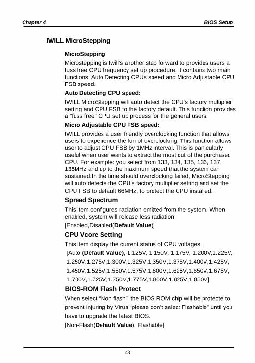
IWILL MicroStepping
MicroSteppingMicrostepping is Iwill's another step forward to provides users afuss free CPU frequency set up procedure. It contains two mainfunctions, Auto Detecting CPUs speed and Micro Adjustable CPUFSB speed.Auto Detecting CPU speed:IWILL MicroStepping will auto detect the CPU's factory multipliersetting and CPU FSB to the factory default. This function providesa "fuss free" CPU set up process for the general users.Micro Adjustable CPU FSB speed:IWILL provides a user friendly overclocking function that allowsusers to experience the fun of overclocking. This function allowsuser to adjust CPU FSB by 1MHz interval. This is particularlyuseful when user wants to extract the most out of the purchasedCPU. For example: you select from 133, 134, 135, 136, 137,138MHz and up to the maximum speed that the system cansustained.In the time should overclocking failed, MicroSteppingwill auto detects the CPU's factory multiplier setting and set theCPU FSB to default 66MHz, to protect the CPU installed.Spread SpectrumThis item configures radiation emitted from the system. Whenenabled, system will release less radiation[Enabled,Disabled(Default Value)]CPU Vcore SettingThis item display the current status of CPU voltages. [Auto (Default Value), 1.125V, 1.150V, 1.175V, 1.200V,1.225V, 1.250V,1.275V,1.300V,1.325V,1.350V,1.375V,1.400V,1.425V, 1.450V,1.525V,1.550V,1.575V,1.600V,1.625V,1.650V,1.675V, 1.700V,1.725V,1.750V,1.775V,1.800V,1.825V,1.850V] BIOS-ROM Flash Protect When select “Non flash”, the BIOS ROM chip will be protecte to prevent injuring by Virus “please don’t select Flashable” until you have to upgrade the latest BIOS. [Non-Flash(Default Value), Flashable]
44
Chapter 4 BIOS Setup
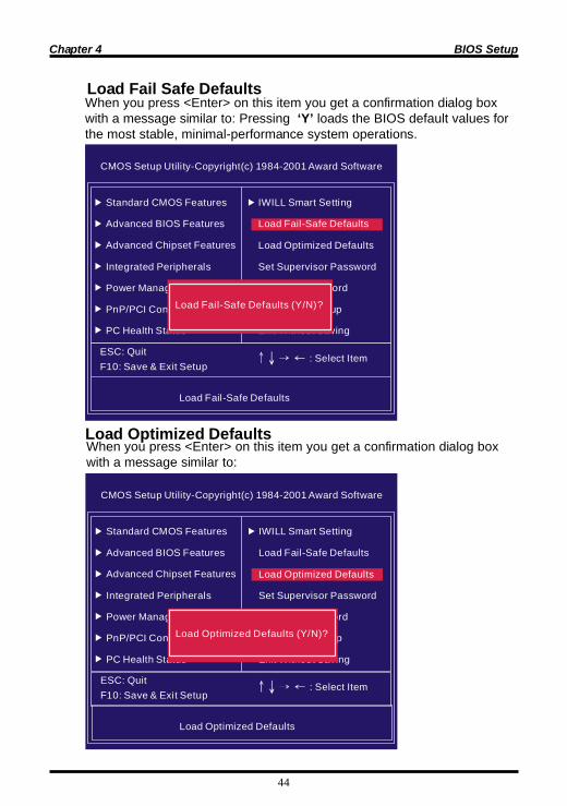
Load Fail Safe Defaults
Load Optimized DefaultsWhen you press <Enter> on this item you get a confirmation dialog boxwith a message similar to:
CMOS Setup Utility-Copyright(c) 1984-2001 Award Software
Standard CMOS Features
Advanced BIOS Features
Advanced Chipset Features
Integrated Peripherals
Power Management Setup
PnP/PCI Configurations
PC Health Status
ESC: QuitF10: Save & Exit Setup
Load Fail-Safe Defaults
: Select Item
IWILL Smart Setting
Load Fail-Safe Defaults
Load Optimized Defaults
Set Supervisor Password
Set User Password
Save & Exit Setup
Exit Without Saving
Load Fail-Safe Defaults (Y/N)?
CMOS Setup Utility-Copyright(c) 1984-2001 Award Software
Standard CMOS Features
Advanced BIOS Features
Advanced Chipset Features
Integrated Peripherals
Power Management Setup
PnP/PCI Configurations
PC Health Status
ESC: QuitF10: Save & Exit Setup
Load Optimized Defaults
: Select Item
IWILL Smart Setting
Load Fail-Safe Defaults
Load Optimized Defaults
Set Supervisor Password
Set User Password
Save & Exit Setup
Exit Without Saving
Load Optimized Defaults (Y/N)?
When you press <Enter> on this item you get a confirmation dialog boxwith a message similar to: Pressing ‘Y’ loads the BIOS default values forthe most stable, minimal-performance system operations.

45
Chapter 4 BIOS Setup
CMOS Setup Utility-Copyright(c) 1984-2001 Award Software
Standard CMOS Features
Advanced BIOS Features
Advanced Chipset Features
Integrated Peripherals
Power Management Setup
PnP/PCI Configurations
PC Health Status
ESC: QuitF10: Save & Exit Setup
Load Optimized Defaults
: Select Item
IWILL Smart Setting
Load Fail-Safe Defaults
Load Optimized Defaults
Set Supervisor Password
Set User Password
Save & Exit Setup
Exit Without SavingEnter Password:
be required to enter the password every time you try to enter BIOS Setupprogram. This prevents an unauthorized person from changing any partof your system configuration. Additionally, if the Security Option field isset as Boot, the BIOS will request a password every time your systemboot. This would prevent unauthorized use of your computer.
If you wish to use this function, bring the cursor to this field, then press<Enter>. The computer will display the message, “Enter Password”.Type your password and press <Enter>. After the message onfirmPassword” is displayed, re-type your password. The SupervisorPassword function will be in effect after you save and exit setup.To disable a password, bring the cursor to this field, then press <Enter>.The computer will display the message, “Enter Password”. Press<Enter>. A message will confirm that the password is disabled. Once thepassword is disabled, the system will boot and you can enter setupprogram freely.
These setup pages are used for password setting. When a password hasbeen enabled and the Security Option field is set as Setup, you will
Set Supervisor/ User Password Setting
46
Chapter 4 BIOS Setup
Exit Without Saving
Save & Exit Setup
CMOS Setup Utility-Copyright(c) 1984-2001 Award Software
Standard CMOS Features
Advanced BIOS Features
Advanced Chipset Features
Integrated Peripherals
Power Management Setup
PnP/PCI Configurations
PC Health Status
ESC: QuitF10: Save & Exit Setup
Save Data to CMOS
: Select Item
IWILL Smart Setting
Load Fail-Safe Defaults
Load Optimized Defaults
Set Supervisor Password
Set User Password
Save & Exit Setup
Exit Without Saving
SAVE to CMOS and EXIT(Y/N)?
CMOS Setup Utility-Copyright(c) 1984-2001 Award Software
Standard CMOS Features
Advanced BIOS Features
Advanced Chipset Features
Integrated Peripherals
Power Management Setup
PnP/PCI Configurations
PC Health Status
ESC: QuitF10: Save & Exit Setup
Abandon all Datas
: Select Item
IWILL Smart Setting
Load Fail-Safe Defaults
Load Optimized Defaults
Set Supervisor Password
Set User Password
Save & Exit Setup
Exit Without SavingQuit Without Saving (Y/N)?
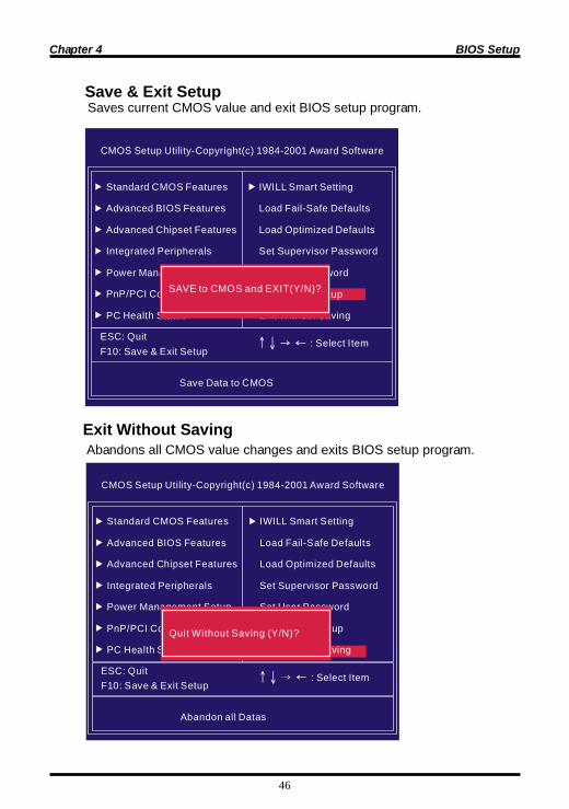
Saves current CMOS value and exit BIOS setup program.
Abandons all CMOS value changes and exits BIOS setup program.

47
Chapter 5 On board Audio
Audio Features
Special Feature1. Full-duplex playback and recording. Built-in 16-bit CODEC.2. HRTF 3D positional audio, supporting both DirectSound 3D&A3D interfaces. Also supports earphones, 2/4/6 channel speakers mode.3. Support Windows 98/Windows 2000 and Windows NT 4.0.4.Built-in 32 OHM Earphone buffer.5. MPU-401 Game/Midi port and legacy audio SB Pro support.6. Downloadable Wave Table Synthesizer, supporting Direct Music.
Digital Audio (SPDIF IN/OUT)1. Up to 24-bit stereo 44KHz sampling rate; voice playback/ recording2. Full-duplex playback and recording. 120dB audio quality measured.3. Auto detectable SPDIF/IN signal level from 0.5V to 5V.
120 dB audio quality in playback, recording, and by pass modes.
On board Audio

Chapter 5 On board Audio
48
Stereo Mixer
Game and Midi Interface Fully compatible with MPU-401 Midi UART and Sound Blaster
1. Stereo analog mixing from CD-Audio and Line-in2. Stereo digital mixing from Voice, FM/Wave-table, and Digital CD-Audio3. Mono mixing from MIC. Software adjustable volume.
Midi mode/Standard IBM PC joystick/game port

49
Chapter 5 On board Audio
IWILL 6Channels Audio/ SuperAudio (Optional)
5PJ rotcennoC)O/IlatigiD(noisnetxEoiduA
7PJ NIFIDPS-DC
01PJ tceleSretneC/SSAB
NI-eniL oeretsfotroptuptuooiduaehtottcennoCNI-ENIL
NI-ciM )onoM(enohporciMehtottcennoC
rekaepS-tnorF foNI-OIDUArosenohpraeroreifilpmaehthtiwsrekaepsottuptuOoeretsemoh
rekaepS-raeR edomsrekaepslennahcxis/ruofelihwsrekaepsraerehtottcennoCdelbanesi
SSAB/retneC srekaepslennahcxiselihwSSABdnarekaepsretnecehtottcennoCdelbanesiedom
IDIM/EMAG ecafretniIDIMgnisusecivedrokcitsyoJottcennoC
TUO/NIFIDPSACR csiDiniMdnaTADsahcussecivedoidualatigidotstcennoCtuptuo/tupniACRaiv,sredrocer
TUO/NIFIDPSlacitpO csiDiniMdnaTADsahcussecivedoidualatigidotstcennoCtuptuo/tupnilacitpoaiv,sredrocer
JP10 function
exChange(BASS/Center) Channel
123
456
Default
123
456
BASS channelCenter channel
BASSlCenter channel
J10
Rear-Speaker
Center/BASS
Audio Cable
6Channels Audio
6CH-Audio
J5
123
456J7
Front-Speaker
Line-INMIC-IN
Game/MIDI
Connectors and Jumpers

Chapter 5 On board Audio
50
J10
Rear-Speaker
Center/BASS
RCA SPDIF IN
Optical SPDIF IN
RCA SPDIF OUT
Optical SPDIF OUT
SuperAudio(Optional)
Aud io Ca b le
Front-Speaker
Line-IN
MIC-INGame/MIDISuperA udio
J5
123
456J7
IWILL 6Channels Audio IWILL SuperAudio (Optional)
51
Chapter 5 On board Audio
Win 95/98/ME/2000 Un-Installation
1. Click “Start”2. Select “Program.”3. Find “Uninstall device drivers and applications” program in PCI audio applications.4. Run it.5. Follow the on-screen instructions to uninstall the device drivers or applications.
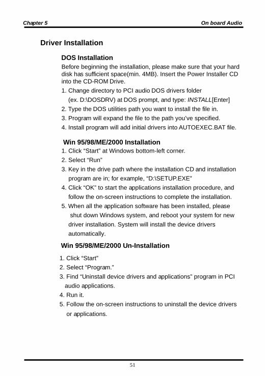
Before beginning the installation, please make sure that your harddisk has sufficient space(min. 4MB). Insert the Power Installer CDinto the CD-ROM Drive.1. Change directory to PCI audio DOS drivers folder (ex. D:\DOSDRV) at DOS prompt, and type: INSTALL[Enter]2. Type the DOS utilities path you want to install the file in.3. Program will expand the file to the path you’ve specified.4. Install program will add initial drivers into AUTOEXEC.BAT file.
DOS Installation
Driver Installation
Win 95/98/ME/2000 Installation1. Click “Start” at Windows bottom-left corner.2. Select “Run”3. Key in the drive path where the installation CD and installation program are in; for example, “D:\SETUP.EXE”4. Click “OK” to start the applications installation procedure, and follow the on-screen instructions to complete the installation.5. When all the application software has been installed, please shut down Windows system, and reboot your system for new driver installation. System will install the device drivers automatically.

Chapter 5 On board Audio
52
We recommend that you have Microsoft Windows NT intalled, andremove any exsisting sound drivers from your current system,before you install this PCI sound device driver.1. Click “Start” , move the highlight bar to “Setting”, and select the “Control Panel”.2. Double-click “Multimedia.”3. Select “Devices”, and press “Add”4. Select “Unlisted or Updated Driver” in List of Drivers.”5. Specify the drive path where NT drivers are in (such as D:\NT40\DRV).6. Select “C-Media CM8738,” and press “OK”.7. Select proper I/O value.8. Press “OK.”9. Restart the system when being asked.10. Now, you have already installed the PCI Audio Adapter under Microsoft Windows NT 4.0 successfully. If you want to install the Windows applications, continue the following steps.11. Click “Start”12. Select “Run”13. Key in drive path where the Windows NT application installation program are in; for example, “D:\NT40\APP\SETUP.EXE14. Click “OK” to start the installation procedure, and follow the on- screen instructions to complete the installation. When all of application software has been installed, shut down the Windows NT system, then reboot your system.
Windows NT4.0 Installation
53
Chapter 5 On board Audio
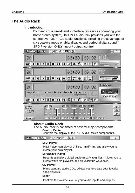
About Audio Rack The Audio Rack is consisted of several major components.
Controls the display of the PCI Audio Rack’s components. Control Center
IntroductionBy means of a user-friendly interface (as easy as operating yourhome stereo system), this PCI audio rack provides you with thecontrol over your PC’s audio functions, including the advantage ofsix speakers mode enable/ disable, and perfect digital sound (SPDIF version ONLY) input / output. control.
The Audio Rack
MIDI PlayerMIDI Player can play MIDI files, *.mid/*.rmi, and allow you tocreate your own playlist.
MP3/Wave PlayerRecords and plays digital audio (mp3/wave) files. Allows you tocreate wave file playlists, and playback the wave files.
CD PlayerPlays standard audio CDs. Allows you to create your favoritesong playlists.
MixerControls the volume level of your audio inputs and outputs

Chapter 5 On board Audio
54
Volume Control
For each output signal, the control slider regulates the loudness whereasa horizontal slider the balance between the two speakers. The mutebutton can temporarily stop the output without changing slider positions.A button with a lit LED means the output is available, and vice versa.Several output signals can usually be enabled at once.Volume: This is the master control over all outputs. The power of anoutputRe signal is determined by both of the volume slider and theslider for the individual output. To modify all the outputs, adjust thevolume slider. To change individual output(s), adjust its(their) slider(s).CD: Regulates the CD drive audio input level.MIC: Regulates the input level of microphone.WAVE: Regulates wave (voice) playback levels.MIDI: Regulates the MIDI music play level.AUX IN: Regulates the Auxiliary input play level.MONO IN: Regulates the Mono input level.LINE IN: Regulates the Line-In levels.Advanced: Regulates the advanced settings.
Recording Control
For each input signal, a control slider regulates the loudness whereas a horizontal slider the balance between the two channels. The se lect button can temporarily select input signal without changing slider positions. A button with a lit LED means it is available, and vice versa.
CD: Regulates the CD drive audio input level. MIC: Regulates the input level of microphone. WAVE: Regulates wave (voice) playback level. FM: Regulates the FM music play level. AUX IN: Regulates the Auxiliary input play level. LINE IN: Regulates the Line-In level. SPDIF IN: Enables the recording from SPDIF in. SPDIF-in is mutu ally exclusive with other input signals. Advanced: Regulates the advanced settings.
Mixer
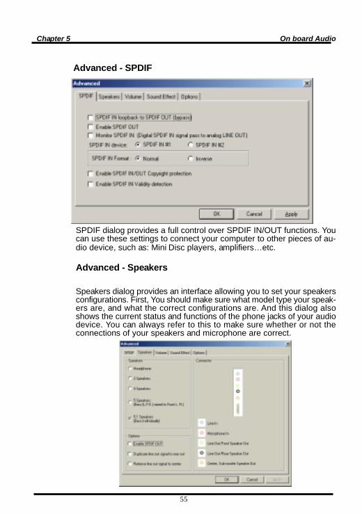
Advanced - SPDIF
SPDIF dialog provides a full control over SPDIF IN/OUT functions. Youcan use these settings to connect your computer to other pieces of au-dio device, such as: Mini Disc players, amplifiers…etc.
Advanced - Speakers
Speakers dialog provides an interface allowing you to set your speakersconfigurations. First, You should make sure what model type your speak-ers are, and what the correct configurations are. And this dialog alsoshows the current status and functions of the phone jacks of your audiodevice. You can always refer to this to make sure whether or not theconnections of your speakers and microphone are correct.
Chapter 5 On board Audio
55

Chapter 5 On board Audio
56
Advanced - Sound effects
Sound effects dialog allows you to modify the special effects of thesong and game being played. Currently, these effectors can only beused for the player or the game which utilizes DirectSound 2D and 3Dto playback their music.
Advanced - Options
Options dialog provides a hot key setting to control the Mixer in aneasy way. Please note that other applications might be affected by thisif you use the same hot key setting.
Please use ‘Load Mixer Defaults’ to change all settings to default values.