t8 eom - a&m industrial pumps...
TRANSCRIPT

S i m p l i f y y o u r p r o c e s s
E n g i n e e r i n g O p e r a t i o n &M a i n t e n a n c e
T8
WIL-10271-E-02REPLACES WIL-10271-E-01
Original™ Series METAL Pumps
EOM

Cla
ss
I & II Ozone
Depleting Substanc
esNON
USEU.S. Clean Air Act
Amendments of 1990
T A B L E O F C O N T E N T S
SECTION 1 CAUTIONS—READ FIRST! . . . . . . . . . . . . . . . . . . . . . . . . . . . . . . . . . . . . . . . . . . . . . .1
SECTION 2 WILDEN PUMP DESIGNATION SYSTEM . . . . . . . . . . . . . . . . . . . . . . . . . . . . . . . . .2
SECTION 3 HOW IT WORKS—PUMP & AIR DISTRIBUTION SYSTEM . . . . . . . . . . . . . . . .3
SECTION 4 DIMENSIONAL DRAWINGS . . . . . . . . . . . . . . . . . . . . . . . . . . . . . . . . . . . . . . . . . . . . .4
SECTION 5 PERFORMANCEA. T8 Metal
Rubber-Fitted . . . . . . . . . . . . . . . . . . . . . . . . . . . . . . . . . . . . . . . . . . . . . . . . . . . . . . . .6
B. Suction Lift Curves . . . . . . . . . . . . . . . . . . . . . . . . . . . . . . . . . . . . . . . . . . . . . . . . . . . . . .7
SECTION 6 SUGGESTED INSTALLATION, OPERATION & TROUBLESHOOTING . . . . . . . .9
SECTION 7 DISASSEMBLY / REASSEMBLY . . . . . . . . . . . . . . . . . . . . . . . . . . . . . . . . . . . . . . . .12
SECTION 8 EXPLODED VIEW AND PARTS LISTINGT8 Metal Rubber-Fitted . . . . . . . . . . . . . . . . . . . . . . . . . . . . . . . . . . . . . . . . . . . . . . . . . . . .16
SECTION 9 ELASTOMER . . . . . . . . . . . . . . . . . . . . . . . . . . . . . . . . . . . . . . . . . . . . . . . . . . . . . . . . . . .20

WIL-10271-E-02 1 WILDEN PUMP & ENGINEERING, LLC
TEMPERATURE LIMITS: Neoprene –17.8°C to 93.3°C 0°F to 200°F Buna-N –12.2°C to 82.2°C 10°F to 180°F EPDM –51.1°C to 137.8°C –60°F to 280°F Viton® –40°C to 176.7°C –40°F to 350°F Wil-Flex™ –40°C to 107.2°C –40°F to 225°F Polyurethane 12.2°C to 65.6°C 10°F to 150°F Saniflex™ –28.9°C to 104.4°C –20°F to 220°F PTFE 4.4°C to 104.4°C 40°F to 220°F Tetra-Flex™PTFE 4.4°C to 107.2°C 40°F to 225°F Fluoro-Seal™ –40°C to 232°C –40°F to 450°F
CAUTION: When choosing pump materials, be sure to check the temperature limits for all wetted compo-nents. Example: Viton® has a maximum limit of 176.7°C (350°F) but polypropylene has a maximum limit of only 79°C (175°F).
CAUTION: Maximum temperature limits are based upon mechanical stress only. Certain chemicals will significantly reduce maximum safe operating tempera-tures. Consult engineering guide for chemical compat-ibility and temperature limits.
CAUTION: Always wear safety glasses when operat-ing pump. When diaphragm rupture occurs, material being pumped may be forced out air exhaust.
WARNING: Prevention of static sparking — If static sparking occurs, fire or explosion could result. Pump, valves, and containers must be properly grounded when handling flammable fluids and whenever discharge of static electricity is a hazard.
CAUTION: Before any maintenance or repair is attempted, the compressed air line to the pump should be disconnected and all air pressure allowed to bleed from pump. Disconnect all intake, discharge and air lines. Drain the pump by turning it upside down and allowing any fluid to flow into a suitable container.
CAUTION: Blow out air line for 10 to 20 seconds before attaching to pump to make sure all pipe line debris is clear. Use an in-line air filter. A 5µ (micron) air filter is recommended.
WARNING: Tighten all clamp bands and retainers prior to installation. Fittings may loosen during transportation.
NOTE: Before starting disassembly, mark a line from each liquid chamber to its corresponding air chamber. This line will assist in proper alignment during reassembly.
CAUTION: Verify the chemical compatibility of the process and cleaning fluid to the pump’s component materials in the Chemical Resistance Guide (see E4).
CAUTION: When removing the end cap using compressed air, the air valve end cap may come out with considerable force. Hand protection such as a padded glove or rag should be used to capture the end cap.
NOTE: All non lube-free air-operated pumps must be lubricated. Wilden suggests an arctic 5 weight oil (ISO grade 15). Do not over-lubricate pump. Over-lubrica-tion will reduce pump performance.
S e c t i o n 1
C A U T I O N S — R E A D F I R S T !

WILDEN PUMP & ENGINEERING, LLC 2 WIL-10271-E-02
S e c t i o n 2
P U M P D E S I G N A T I O N S Y S T E M
T8 ORIGINAL™ METAL51 mm (2") Pump Maximum Flow Rate:587 lpm (155 gpm)
SPECIALTY CODES
0014 BSPT
NOTE: MOST ELASTOMERIC MATERIALS USE COLORED DOTS FOR IDENTIFICATION.
MATERIAL CODESMODEL
T = TURBO-FLO™
WETTED PARTS & OUTER PISTON
AA = ALUMINUM / ALUMINUMWW = CAST IRON / CAST IRON
AIR CHAMBERS
A = ALUMINUM
CENTER BLOCK
A = ALUMINUM
AIR VALVE
B = BRASSD = BRASS W/OIL BOTTLE
DIAPHRAGMSBNS = BUNA-N (Red Dot)NES = NEOPRENE (Green Dot)
VALVE BALL
BN = BUNA-N (Red Dot)NE = NEOPRENE (Green Dot)
VALVE SEATBN = BUNA-N (Red Dot)NE = NEOPRENE (Green Dot)
LEGEND T8 / XXXXX / XXX / XX / XX / XXXX
VALVE SEATMODEL
VALVE BALLSDIAPHRAGMS
AIR VALVECENTER BLOCK
AIR CHAMBERSWETTED PARTS & OUTER PISTON
SPECIALTYCODE(if applicable)

WIL-10271-E-02 3 WILDEN PUMP & ENGINEERING, LLC
The Wilden diaphragm pump is an air-operated, positive displacement, self-priming pump. These drawings show the flow pattern through the pump upon its initial stroke. It is assumed the pump has no fluid in it prior to its initial stroke.
FIGURE 1 The air valve directs pres-surized air to the back side of diaphragm A. The compressed air is applied directly to the liquid column separated by elas-tomeric diaphragms. The diaphragm acts as a separation membrane between the compressed air and liquid, balanc-ing the load and removing mechani-cal stress from the diaphragm. The compressed air moves the diaphragm away from the center block of the pump. The opposite diaphragm is pulled in by the shaft connected to the pressur-ized diaphragm. Diaphragm B is on its suction stroke; air behind the diaphragm has been forced out to the atmosphere through the exhaust port of the pump. The movement of diaphragm B toward the center block of the pump creates a vacuum within chamber B. Atmospheric pressure forces fluid into the inlet mani-fold forcing the inlet valve ball off its seat. Liquid is free to move past the inlet valve ball and fill the liquid chamber (see shaded area).
FIGURE 2 When the pressurized diaphragm, diaphragm A, reaches the limit of its discharge stroke, the air valve redirects pressurized air to the back side of diaphragm B. The pressurized air forces diaphragm B away from the center block while pulling diaphragm A to the center block. Diaphragm B is now on its discharge stroke. Diaphragm B forces the inlet valve ball onto its seat due to the hydraulic forces developed in the liquid chamber and manifold of the pump. These same hydraulic forces lift the discharge valve ball off its seat, while the opposite discharge valve ball is forced onto its seat, forcing fluid to flow through the pump discharge. The move-ment of diaphragm A toward the center block of the pump creates a vacuum within liquid chamber A. Atmospheric pressure forces fluid into the inlet mani-fold of the pump. The inlet valve ball is forced off its seat allowing the fluid being pumped to fill the liquid chamber.
FIGURE 3 At completion of the stroke, the air valve again redirects air to the back side of diaphragm A, which starts diaphragm B on its exhaust stroke. As the pump reaches its original starting point, each diaphragm has gone through one exhaust and one discharge stroke. This constitutes one complete pump-ing cycle. The pump may take several cycles to completely prime depending on the conditions of the application.
LEFT STROKE
➤
➤
RIGHT STROKE MID STROKE
S e c t i o n 3
H O W I T W O R K S — P U M P D I S T R I B U T I O N S Y S T E M

WILDEN PUMP & ENGINEERING, LLC 4 WIL-10271-E-02
F
P
M
N
K L
A
C
B
D
E
J
H
51 mm (2”) FNPT DISCHARGE
51 mm (2”) FNPT INLET
51 mm (2”) FNPT
19 mm (3/4”) FNPT AIR INLET
19 mm (3/4”) FNPT AIR EXHAUST
G - ALUM.F - 316 S.S., C.I. DIMENSIONS
ITEM METRIC (mm) STANDARD (inch)
A 404 15.9B 48 1.9C 630 24.8D 668 26.3E 361 14.2F 58 2.3G 61 2.4H 272 10.7J 343 13.5K 229 9.0L 254 10.0M 257 10.1N 312 12.3P 15 0.6
S e c t i o n 4
D I M E N S I O N A L D R A W I N G
T8 Metal

S e c t i o n 5 A
Spectrom is not your typical after market part supplier. We do not simply sell pump parts; we
provide value added procurement solutions.
Our unique network enables us to pur-chase effectively, resulting in low cost solutions. We also know that low purchase
price is not enough - quality, integrity and inventory are also important. Spectrom is struc-
tured to provide Pre and Post sales support, giving our customers value added application and pump
knowledge.
Contact us to have a procurement solution developed for you. We don’t just fit you into a generic system, we develop specific
solutions that achieve results.
Spectrom will ship your order from our facility within 3 working days!
Sleep easier with
A ?FindingSpares
Nightmare
WARNING: These parts may exhibit better life than OEM parts.
1-909-512-1261 www.spectromparts.com
KNOWLEDGE& SERVICE
• Competitive pricing• Delivery• Service• Inventory
PUMP PARTS(Low Cost)
• Diaphragms• Valve balls• Valve seats
PRODUCTS: AODDP(Air Operated Double Diaphragm Pumps)
• Warren-Rupp®
• ARO®
• Other
WILDEN PUMP & ENGINEERING, LLC 6 WIL-10271-E-02
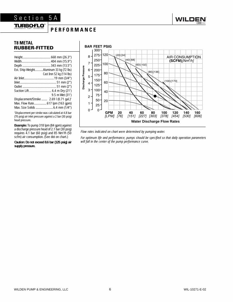
Height .................................. 668 mm (26.3")Width ................................... 404 mm (15.9")Depth .................................. 343 mm (13.5")Est. Ship Weight ..........Aluminum 33 kg (72 lbs)
Cast Iron 52 kg (114 lbs)Air Inlet ....................................19 mm (3/4")Inlet ............................................ 51 mm (2")Outlet ......................................... 51 mm (2")Suction Lift ........................... 6.4 m Dry (21')
9.5 m Wet (31')Displacement/Stroke ....... 2.69 l (0.71 gal.)1
Max. Flow Rate ............... 617 lpm (163 gpm)Max. Size Solids .....................6.4 mm (1/4")1Displacement per stroke was calculated at 4.8 bar (70 psig) air inlet pressure against a 2 bar (30 psig) head pressure.
Example: To pump 318 lpm (84 gpm) against a discharge pressure head of 2.1 bar (30 psig) requires 4.1 bar (60 psig) and 85 Nm3/h (50 scfm) air consumption. (See dot on chart.)
Caution: Do not exceed 8.6 bar (125 psig) air supply pressure.
Flow rates indicated on chart were determined by pumping water.
For optimum life and performance, pumps should be specified so that daily operation parameters will fall in the center of the pump performance curve.
[LPM]
Water Discharge Flow Rates
S e c t i o n 5 A
P E R F O R M A N C E
T8 METALRUBBER-FITTED

WIL-10271-E-02 7 WILDEN PUMP & ENGINEERING, LLC
Suction lift curves are calibrated for pumps operating at 305 m (1,000') above sea level. This chart is meant to be a guide only. There are many variables which can affect your pump’s operating characteristics. The number of intake
and discharge elbows, viscosity of pumping fluid, elevation (atmospheric pressure) and pipe friction loss all affect the amount of suction lift your pump will attain.
Dry
Vac
uu
m
FT H2O
S e c t i o n 5 B
S U C T I O N L I F T C U R V E
T8 METAL

S e c t i o n 5 B
E L A S T O M E R K I T S
• Elastomer & ADS Repair Kits
• All Sizes Available
• PTFE, Rubber & TPE Elastomers
• One Part Number Simplifi es Inventory
• Eliminates Order Errors
• Reduces Re-Build Time
• Rejuvenates Your Pump
Program Details:
NOTE: See Section 9.

WIL-10271-E-02 9 WILDEN PUMP & ENGINEERING, LLC
The Model T8 Metal pump has a 51 mm (2") inlet and 51 mm (2") outlet and is designed for flows to 617 lpm (163 gpm). Refer to Section 5 for performance characteristics. The T8 Metal pump is manufactured with wetted parts of aluminum, 316 Stainless Steel, and Cast Iron. The center block of the T8 Metal pump is constructed of polypropylene, aluminum, nickel-plated aluminum, PTFE-coated aluminum, or stainless steel. A variety of diaphragms, valve balls, valve seats and o-rings are available to satisfy temperature, chemical compat-ibility, abrasion and flex concerns.
The suction pipe size should be at least 51 mm (2") diameter or larger if highly viscous material is being pumped. The suction hose must be non-collapsible, reinforced type as the T8 is capable of pulling a high vacuum. Discharge piping should be at least 51 mm (2"); larger diameter can be used to reduce friction losses. It is critical that all fittings and connec-tions are airtight or a reduction or loss of pump suction capa-bility will result.
INSTALLATION: Months of careful planning, study, and selec-tion efforts can result in unsatisfactory pump performance if installation details are left to chance.
Premature failure and long term dissatisfaction can be avoided if reasonable care is exercised throughout the installation process.
LOCATION: Noise, safety, and other logistical factors usually dictate where equipment be situated on the production floor. Multiple installations with conflicting requirements can result in congestion of utility areas, leaving few choices for siting of additional pumps.
Within the framework of these and other existing conditions, every pump should be located in such a way that five key factors are balanced against each other to maximum advan-tage.
ACCESS: First of all, the location should be accessible. If it’s easy to reach the pump, maintenance personnel will have an easier time carrying out routine inspections and adjustments. Should major repairs become necessary, ease of access can play a key role in speeding the repair process and reducing total downtime.
AIR SUPPLY: Every pump location should have an air line large enough to supply the volume of air necessary to achieve the desired pumping rate (see Section 5). Use air pressure up to a maximum of 8.6 bar (125 psig) depending upon pumping requirements.
For best results, the pumps should use a 5 micron air filter, needle valve and regulator. The use of an air filter before the pump will insure that the majority of any pipeline contami-nants will be eliminated.
SOLENOID OPERATION: When operation is controlled by a solenoid valve in the air line, three-way valves should be used. This valve allows trapped air between the valve and the pump to bleed off which improves pump performance. Pumping volume can be determined by counting the number of strokes per minute and then multiplying the figure by the displacement per stroke.
MUFFLER: Sound levels are reduced below OSHA speci-fications using the standard Wilden muffler element. Other
mufflers can be used to further reduce sound levels, but they usually reduce pump performance.
ELEVATION: Selecting a site that is well within the pump’s dynamic lift capability will assure that loss-of-prime trou-bles will be eliminated. In addition, pump efficiency can be adversely affected if proper attention is not given to site location.
PIPING: Final determination of the pump site should not be made until the piping problems of each possible location have been evaluated. The impact of current and future installations should be considered ahead of time to make sure that inad-vertent restrictions are not created for any remaining sites.
The best choice possible will be a site involving the short-est and the straightest hook-up of suction and discharge piping. Unnecessary elbows, bends, and fittings should be avoided. Pipe sizes should be selected so as to keep friction losses within practical limits. All piping should be supported independently of the pump. In addition, the piping should be aligned so as to avoid placing stresses on the pump fittings.
Flexible hose can be installed to aid in absorbing the forces created by the natural reciprocating action of the pump. If the pump is to be bolted down to a solid foundation, a mount-ing pad placed between the pump and foundation will assist in minimizing pump vibration. Flexible connections between the pump and rigid piping will also assist in minimizing pump vibration. If quick-closing valves are installed at any point in the discharge system, or if pulsation within a system becomes a problem, a surge suppressor should be installed to protect the pump, piping and gauges from surges and water hammer.
If the pump is to be used in a self-priming application, be sure that all connections are airtight and that the suction lift is within the model’s ability. Note: Materials of construction and elastomer material have an effect on suction lift parameters. Please refer to Section 6 for specifics.
When pumps are installed in applications involving flooded suction or suction head pressures, a gate valve should be installed in the suction line to permit closing of the line for pump service.
Pumps in service with a positive suction head are most effi-cient when inlet pressure is limited to 0.5–0.7 bar (7–10 psig). Premature diaphragm failure may occur if positive suction is 0.7 bar (10 psig) and higher.
THE MODEL T8 WILL PASS 6.4 mm (1/4") SOLIDS. WHEN-EVER THE POSSIBILITY EXISTS THAT LARGER SOLID OBJECTS MAY BE SUCKED INTO THE PUMP, A STRAINER SHOULD BE USED ON THE SUCTION LINE.
BLOW OUT AIR LINE FOR 10 TO 20 SECONDS BEFORE ATTACHING TO PUMP TO MAKE SURE ALL PIPE LINE DEBRIS IS CLEAR. ALWAYS USE AN IN-LINE AIRFILTER.
CAUTION: DO NOT EXCEED 8.6 BAR (125 PSIG) AIR SUPPLY PRESSURE. (3.4 BAR [50 PSIG] FOR UL MODELS.)
CAUTION: DO NOT HANG T8 STALLION PUMPS BY THEIR HANDLES.
S e c t i o n 6
S U G G E S T E D I N S T A L L A T I O N

WILDEN PUMP & ENGINEERING, LLC 10 WIL-10271-E-02
OPERATION: The T8 is not pre-lubricated, and may require in-line lubrication. Pump discharge rate can be controlled by limiting the volume and/or pressure of the air supply to the pump (preferred method). An air regulator is used to regulate air pressure. A needle valve is used to regulate volume. Pump discharge rate can also be controlled by throttling the pump discharge by partially closing a valve in the discharge line of the pump. This action increases friction loss which reduces flow rate. (See Section 5.) This is useful when the need exists to control the pump from a remote location. When the pump discharge pressure equals or exceeds the air supply pressure, the pump will stop; no bypass or pressure relief valve is needed, and pump damage will not occur. The pump has reached a “dead-head” situation and can be restarted by reducing the fluid discharge pressure or increasing the air inlet pressure. The Wilden T8 pump runs solely on compressed air and does not generate heat, therefore your process fluid temperature will not be affected.
MAINTENANCE AND INSPECTIONS: Since each applica-tion is unique, maintenance schedules may be different for every pump. Frequency of use, line pressure, viscosity and abrasiveness of process fluid all affect the parts life of a Wilden pump. Periodic inspections have been found to offer the best means for preventing unscheduled pump downtime. Personnel familiar with the pump’s construction and service should be informed of any abnormalities that are detected during operation.
RECORDS: When service is required, a record should be made of all necessary repairs and replacements. Over a period of time, such records can become a valuable tool for predicting and preventing future maintenance problems and unscheduled downtime. In addition, accurate records make it possible to identify pumps that are poorly suited to their applications.
AIR OPERATED PUMPS: To stop the pump from oper-ating in an emergency situation, simply close the “shut off” valve (user supplied) installed in the air supply line. A properly functioning valve will stop the air supply to the pump, therefore stopping output. This shut off valve should be located far enough away from the pumping equipment such that it can be reached safely in an emergency situation.
ACCU-FLO™ PUMPS: Accu-Flo™ pumps function with solenoid valves and require an electrical control circuit to supply pulses. Under normal operating conditions, the control circuit is sufficient for starting and stopping the pump. However, the shut off valve (user supplied) installed in the air supply line can be used to stop the pump if necessary. Therefore, it should be located far enough away from the pumping equipment such that it can be reached safely in an emergency situation.
NOTE: In the event of a power failure, the shut off valve should be closed, if the restarting of the pump is not desirable once power is regained.
®
S e c t i o n 6
S U G G E S T E D I N S T A L L A T I O N
S U G G E S T E D O P E R A T I O N & M A I N T E N A N C E

WIL-10271-E-02 11 WILDEN PUMP & ENGINEERING, LLC
Pump will not run or runs slowly.1. Check air inlet screen and air filter for debris.2. Check for sticking air valve, flush air valve in solvent.3. Check for worn out air valve. If piston face in air valve is
shiny instead of dull, air valve is probably worn beyond working tolerances and must be replaced.
4. Check center block Glyd™ rings. If worn excessively, they will not seal and air will simply flow through pump and out air exhaust. Use only Wilden Glyd™ rings as they are of special construction.
5. Check for rotating piston in air valve.6. Check type of lubricant being used. A higher viscosity
oil than suggested may cause the piston to stick or run erratically. Wilden suggests the use of an oil with arctic characteristics (ISO 15-5 wt.).
Pump runs but little or no product flows.1. Check for pump cavitation; slow pump speed down to
match thickness of material being pumped.2. Check for sticking ball check valves. If material being
pumped is not compatible with pump elastomers, swell-ing may occur. Replace ball check valves and o-rings with the proper elastomers.
3. Check to make sure all suction connections are air tight, especially clamp bands around intake balls.
Pump air valve freezes.Check for excessive moisture in compressed air. Either install dryer or hot air generator for compressed air.
Air bubbles in pump discharge.1. Check for ruptured diaphragm.2. Check tightness of clamp bands, especially at intake
manifold.
Product comes out air exhaust.1. Check for diaphragm rupture.2. Check tightness of piston plates to shaft.
Pump rattles.1. See E9 Troubleshooting Guide.2. Create false discharge head or suction lift.
S e c t i o n 6
T R O U B L E S H O O T I N G

WILDEN PUMP & ENGINEERING, LLC 12 WIL-10271-E-02
Step 2. Figure 2
Utilizing the 13 mm (1/2") box wrench, remove the two small clamp bands that fasten the discharge manifold to the liquid chambers.
Step 3. Figure 3
Remove the discharge manifold to expose the valve balls and seats. Inspect the ball cage area of the manifold for excessive wear or damage. Remove the discharge valve balls, seats and o-rings from the discharge manifold and inspect for nicks, gouges, chemical attack or abrasive wear. Replace worn parts with genuine Wilden parts for reliable performance. PTFEo-rings should be replaced when reassembled.
CAUTION: Before any maintenance or repair is attempted, the compressed air line to the pump should be disconnected and all air pressure allowed to bleed from the pump. Discon-nect all intake, discharge, and air lines. Drain the pump by turning it upside down and allowing any fluid to flow into a suitable container. Be aware of any hazardous effects of contact with your process fluid.
The Wilden T8 has a 51 mm (2") inlet and 51 mm (2") outlet and is designed for flows up to 617 lpm (163 gpm). The model T8 is available in aluminum, cast iron, or 316 stainless steel wetted parts. The center block is available in polypropylene, aluminum, nickel-plated aluminum, PTFE-coated aluminum and 316 stainless steel. All o-rings used in the pump are of a special material and shore hardness that should only be replaced with factory-supplied parts.
TOOLS REQUIRED:Adjustable Wrench13 mm (1/2") Socket14 mm (9/16") Box Wrench17 mm (11/16") Socket25 mm (1") Box Wrench or Adjustable WrenchVise equipped with soft jaws (such as plywood, plasticor other suitable material)
NOTE: The model used for these instructions incorporates rubber diaphragms, balls, and seats. Models with PTFE diaphragms, balls and seats are the same except where noted. The procedures for A8 Accu-Flo™ pumps are the same except for the air distribution system.
DISASSEMBLY:
Step 1.
Before starting disassembly, mark a line from each liquid chamber to its corresponding air chamber. This line will assist in proper alignment during reassembly.
Figure 1
S e c t i o n 7
P U M P D I S A S S E M B L Y
WIL-10271-E-02 13 WILDEN PUMP & ENGINEERING, LLC
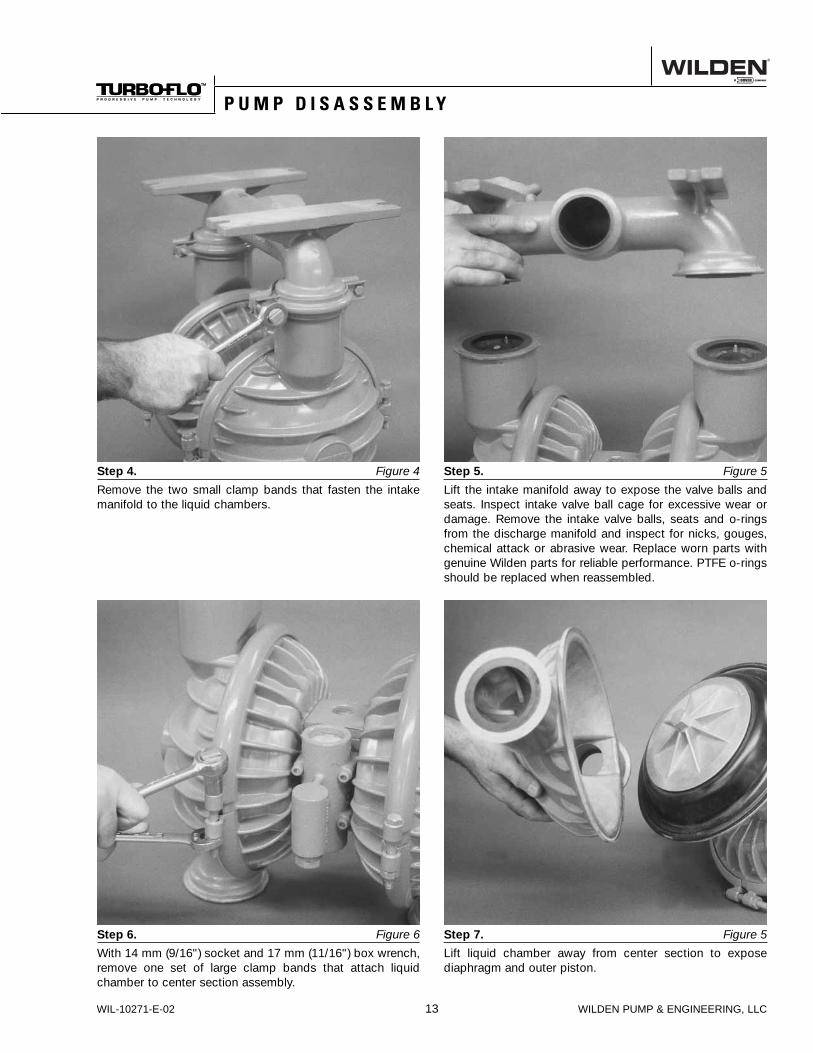
Step 4. Figure 4
Remove the two small clamp bands that fasten the intake manifold to the liquid chambers.
Step 5. Figure 5
Lift the intake manifold away to expose the valve balls and seats. Inspect intake valve ball cage for excessive wear or damage. Remove the intake valve balls, seats and o-rings from the discharge manifold and inspect for nicks, gouges, chemical attack or abrasive wear. Replace worn parts with genuine Wilden parts for reliable performance. PTFE o-rings should be replaced when reassembled.
Step 6. Figure 6
With 14 mm (9/16") socket and 17 mm (11/16") box wrench, remove one set of large clamp bands that attach liquid chamber to center section assembly.
Step 7. Figure 5
Lift liquid chamber away from center section to expose diaphragm and outer piston.
S e c t i o n 7
P U M P D I S A S S E M B L Y
WILDEN PUMP & ENGINEERING, LLC 14 WIL-10271-E-02
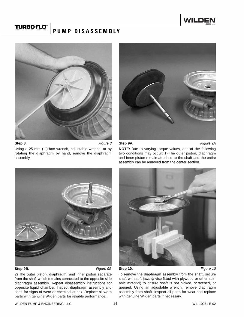
Step 8. Figure 8
Using a 25 mm (1") box wrench, adjustable wrench, or by rotating the diaphragm by hand, remove the diaphragm assembly.
Step 9A. Figure 9A
NOTE: Due to varying torque values, one of the following two conditions may occur: 1) The outer piston, diaphragm and inner piston remain attached to the shaft and the entire assembly can be removed from the center section.
Step 10. Figure 10
To remove the diaphragm assembly from the shaft, secure shaft with soft jaws (a vise fitted with plywood or other suit-able material) to ensure shaft is not nicked, scratched, or gouged. Using an adjustable wrench, remove diaphragm assembly from shaft. Inspect all parts for wear and replace with genuine Wilden parts if necessary.
Step 9B. Figure 9B
2) The outer piston, diaphragm, and inner piston separate from the shaft which remains connected to the opposite side diaphragm assembly. Repeat disassembly instructions for opposite liquid chamber. Inspect diaphragm assembly and shaft for signs of wear or chemical attack. Replace all worn parts with genuine Wilden parts for reliable performance.
S e c t i o n 6
P U M P D I S A S S E M B L Y

WIL-10271-E-02 15 WILDEN PUMP & ENGINEERING, LLC
The air valve assembly consists of both the air valve body and piston and the center block. The unique design of the air valve relies only on differential pressure to effect the diaphragm shift. It is reliable and simple to maintain. The bushing in the center block, along with the diaphragm shaft, provides the “trigger” to tell the air valve to shift. The follow-ing procedure will ensure that the air valve on your Wilden pump will provide long trouble-free service.
AIR VALVE BODY AND PISTONASSEMBLY AND DISASSEMBLY:The air valve body and piston can be disconnected from the pump by removing the four socket head cap screws which attach it to the center block. The piston in the air valve is aluminum with a dark gray anodized coating. The piston should move freely and the ports in the piston should line up with the ports on the face of the air valve body (see below). The piston should also appear to be a dull, dark gray in color. If the piston appears to be a shiny aluminum color, the air valve is probably worn beyond working tolerance and should be replaced.
If the piston does not move freely in the air valve, the entire air valve should be immersed in a cleaning solution.
[NOTE: Do not force the piston by inserting a metal object.] This soaking should remove any accumulation of sludge and grit which is preventing the air valve piston from moving freely. Also, remove and clean the air valve screen. If the air valve piston does not move freely after the above cleaning, the air valve should be disassembled as follows: remove the snap ring from the top end of the air valve cylinder and apply an air jet to the 3/16-inch hole on the opposite end of the air valve face. (See Figure C.) CAUTION: The air valve end cap may come out with considerable force. Hand protection such as a padded glove or rag should be used to capture the end cap.
S e c t i o n 8
A I R V A L V E / C E N T E R B L O C K D I S A S S E M B L Y

WILDEN PUMP & ENGINEERING, LLC 16 WIL-10271-E-02
P/N 08-3300-07 BronzeBushing can be pressedinto a stainless steel orcast iron center section.(See Figure F). Wheninstalling a new bush-ing, four bleeder holeswhich allow the pump toexhaust air must be drilled. (See Figure G).
Small nicks can usually be dressed out and the piston returned to service. Make sure that the guide pin is straight and smooth or the piston will not move freely in the cylinder. Clean out anti-centering pin holes located at each side of the piston. Pin holes are located on each side of the annular groove on the top of the piston and travel to each end. New o-rings should be installed on the end caps. Lubricate the o-rings and install the end caps, assuring that proper alignment of the piston and cylinder ports is maintained. (See Figure D). Reinstall air valve to center block of pump. Tighten per the torque specifications in Section 8C.
GLYD™ RING REPLACEMENT:When the Glyd™ rings become worn, they will no longer seal and must be replaced. Due to the design characteristics of the Glyd™ rings, it is suggested that you use the Ringer Seal installation kit when replacing Glyd™ rings. Consult EOM-Ringer for installation instructions.
CENTER BLOCK ASSEMBLY:The pump’s center block consists of a polypropylene or die cast housing with a cast-in bronze bushing. The bushing has eleven grooves cut on the inside diameter. There are seven Glyd™ rings that fit in these grooves (see Figure E). Since these Glyd™ rings form a part of the shifting function of the pump, it is necessary that they be located in the proper grooves. The bronze bushing is replaceable in cast iron or stainless steel center blocks only. When bushing wear becomes excessive, a new center block must be used.
Figure F (Side View)
Figure GCenter Block(Front View)
3/16" DRILLBLEED-OFF
PORT
3/16" DRILLBLEED-OFF
PORT
5/32" DRILLBLEED-OFF
PORT
P/N 08-3800-09-65P/N 08-3210-55-225
Figure E
Grooves inbushing whichcontain Glyd™ rings
S e c t i o n 8
A I R V A L V E / C E N T E R B L O C K D I S A S S E M B L Y
WIL-10271-E-02 17 WILDEN PUMP & ENGINEERING, LLC
ASSEMBLY:Upon performing applicable maintenance to the air distribu-tion system, the pump can now be reassembled. Please refer to the disassembly instructions for photos and parts placement. To reassemble the pump, follow the disassem-bly instructions in reverse order. The air distribution system needs to be assembled first, then the diaphragms and finally the wetted path. Please find the applicable torque speci-fications on this page. The following tips will assist in the assembly process.
• Clean the inside of the center section shaft bushing to ensure no damage is done to new seals.
• Stainless bolts should be lubed to reduce the possibility of seizing during tightening.
• Ensure proper alignment on the sealing surfaces of intake and discharge manifolds.
• Liquid chambers are easier to attach when the diaphragm is inverted. Prior to attaching the second water chamber, push diaphragm assembly so that it is as close as possi-ble to the center section.
• When installing Glyd™ rings, the use of the Wilden Ringer tool simplifies seal installation.
MAXIMUM TORQUE SPECIFICATIONS
Description of Part Metal Pumps
Air Valve 9.6 N•m (85 in-lbs)
Outer Piston (Rubber-fi tted) 108.5 N•m (80 ft-lbs)
Large Clamp Band (All) 47.4 N•m (35 ft-lbs)
Center Block Assembly 31.1 N•m (23 ft-lbs)
S e c t i o n 6
R E A S S E M B L Y H I N T S & T I P S

WILDEN PUMP & ENGINEERING, LLC 18 WIL-10271-E-02
23
27
29
20
18
28
25
26 3032
22
31
16
19
17
21
24
T8 METAL R u b b e r - F i t t e d E X P L O D E D V I E W
S e c t i o n 8
E X P L O D E D V I E W & P A R T S L I S T I N G

WIL-10271-E-02 19 WILDEN PUMP & ENGINEERING, LLC
*Refer to elastomer options in Section 9.1Air valve assy (08-2000-07) includes items 2 thru 6. Air valve assy (08-2080-07) includes items 2 thru 9. 2Oil Bottle (08-2850-01) includes item 8. 3Center block (08-3100-01-225) includes item 13. 4Small Clamp band assy (08-7100-08) includes items 28 and 29. 5Large clamp band assy (08-7300-08) includes items 31 and 32. 6Muffl er (08-3510-99) includes 45 deg. muffl er connector (08-3250-08)NOTE: BSP threads available.
All boldface items are primary wear parts.
E X P L O D E D V I E W & P A R T S L I S T I N G
T8 METAL R u b b e r - F i t t e d P A R T S L I S T I N G
Item Description Qty
T8/AAAABPart No.
T8/AAAADPart No.
T8/WWAABPart No.
1 Air Valve Assy 1 1 08-2000-07 08-2080-07 08-2000-072 Screen 1 08-2500-07 08-2500-07 08-2500-073 End Cap W/ Guide 1 08-2300-23 08-2300-23 08-2300-234 End Cap W/O Guide 1 08-2330-23 08-2330-23 08-2330-235 Retaining Ring 2 08-2650-03 08-2650-03 08-2650-036 O-Ring, End Cap 2 08-2390-52 08-2390-52 08-2390-527 Oil Bottle 2 1 N/A 08-2850-01 N/A8 Pipe Plug 1 N/A 08-7000-07 N/A9 Capillary Rod Assy 1 N/A 08-2900-99 N/A
10 Gasket, Air Valve 1 08-2600-52 08-2600-52 08-2600-5211 Screw, SHC, 5/16-18 x 2 1/4 4 08-6000-08 08-6000-08 08-6000-0812 Center Block 3 1 08-3100-01-225 08-3100-01-225 08-3100-01-22513 Shaft Seal Ring 7 08-3210-55-225 08-3210-55-225 08-3210-55-22514 Gasket, Center Block 2 08-3520-52 08-3520-52 08-3520-5215 Shaft 1 08-3800-09-07 08-3800-09-07 08-3800-09-0716 Chamber, Air 2 08-3650-01 08-3650-01 08-3650-0117 Screw, FHSC, 3/8-16 x 3 9/16 3 08-6200-08 08-6200-08 08-6200-0818 Nut, Cone, 3/8-16 3 08-6550-08 08-6550-08 08-6550-0819 Piston, Inner 2 08-3700-01 08-3700-01 08-3700-0120 Diaphragm, Primary 2 * * *21 Piston, Outer 2 08-4550-01 08-4550-01 08-4550-0222 Chamber, Liquid 2 08-5000-01 08-5000-01 08-5000-0223 Manifold, Discharge 1 08-5020-01 08-5020-01 08-5020-0224 Manifold, Inlet 1 08-5080-01 08-5080-01 08-5080-0225 Valve Ball 4 * * *26 Valve Seat 4 * * *27 Clamp Band Assy, Small 4 4 08-7100-08 08-7100-08 08-7100-0828 Carriage Bolt, 5/16-18 x 1 1/2 8 08-6050-08 08-6050-08 08-6050-0829 Nut, Hex, 5/16-18 8 04-6420-08 04-6420-08 04-6420-0830 Clamp Band Assy, Large 5 2 08-7300-08 08-7300-08 08-7300-0831 Screw, HHC, 3/8-16 x 3 4 08-6120-08 08-6120-08 08-6120-0832 Nut, Heavy Hex, 3/8-16 4 08-6450-08 08-6450-08 08-6450-08
Muffler (Not Shown) 6 1 08-3510-99 08-3510-99 08-3510-99

WILDEN PUMP & ENGINEERING, LLC 20 WIL-10271-E-02
T8 Metal
MATERIALDIAPHRAGMS (2)
P/NVALVE BALLS (4)
P/NVALVE SEATS (4)
P/NNeoprene 08-1010-51 08-1080-51 08-1120-51Buna-N 08-1010-52 08-1080-52 08-1120-52
S e c t i o n 9
E L A S T O M E R O P T I O N S
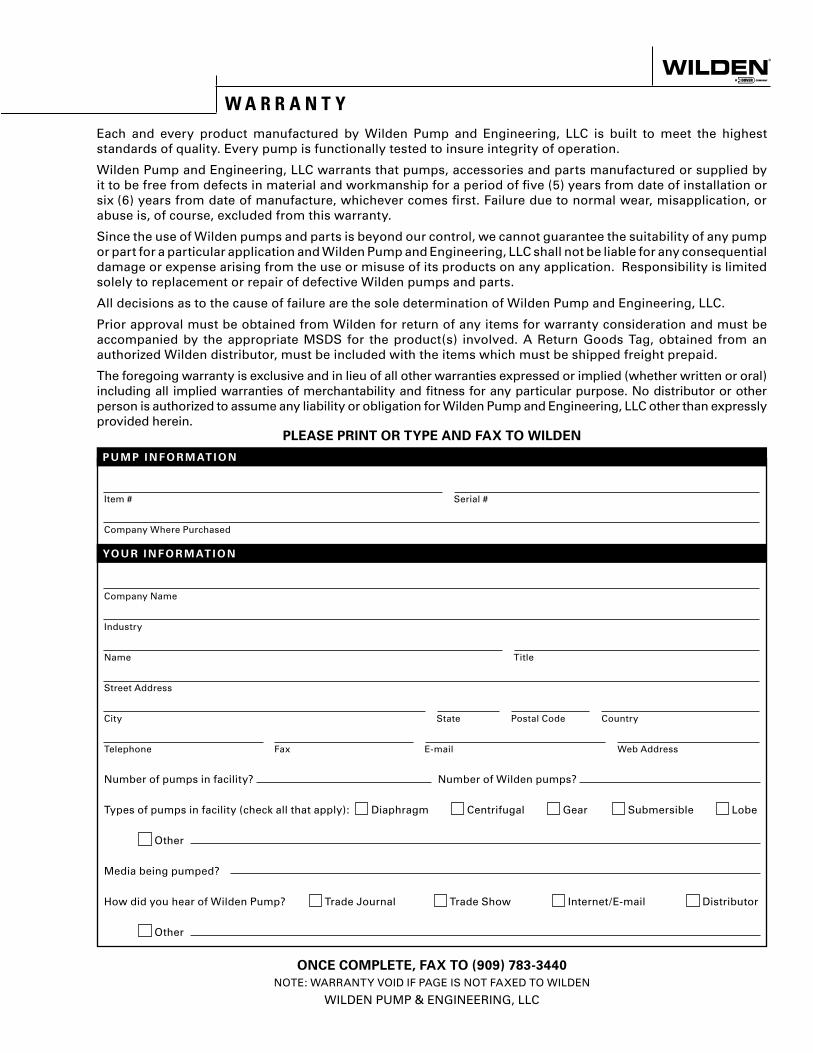
Item # Serial #
Company Where Purchased
Company Name
Industry
Name Title
Street Address
City State Postal Code Country
Telephone Fax E-mail Web Address
Number of pumps in facility? Number of Wilden pumps?
Types of pumps in facility (check all that apply): Diaphragm Centrifugal Gear Submersible Lobe
Other
Media being pumped?
How did you hear of Wilden Pump? Trade Journal Trade Show Internet/E-mail Distributor
Other
P U M P I N F O R M AT I O N
PLEASE PRINT OR TYPE AND FAX TO WILDEN
YO U R I N F O R M AT I O N
ONCE COMPLETE, FAX TO (909) 783-3440
NOTE: WARRANTY VOID IF PAGE IS NOT FAXED TO WILDEN
WILDEN PUMP & ENGINEERING, LLC
W A R R A N T YEach and every product manufactured by Wilden Pump and Engineering, LLC is built to meet the highest standards of quality. Every pump is functionally tested to insure integrity of operation.
Wilden Pump and Engineering, LLC warrants that pumps, accessories and parts manufactured or supplied by it to be free from defects in material and workmanship for a period of five (5) years from date of installation or six (6) years from date of manufacture, whichever comes first. Failure due to normal wear, misapplication, or abuse is, of course, excluded from this warranty.
Since the use of Wilden pumps and parts is beyond our control, we cannot guarantee the suitability of any pump or part for a particular application and Wilden Pump and Engineering, LLC shall not be liable for any consequential damage or expense arising from the use or misuse of its products on any application. Responsibility is limited solely to replacement or repair of defective Wilden pumps and parts.
All decisions as to the cause of failure are the sole determination of Wilden Pump and Engineering, LLC.
Prior approval must be obtained from Wilden for return of any items for warranty consideration and must be accompanied by the appropriate MSDS for the product(s) involved. A Return Goods Tag, obtained from an authorized Wilden distributor, must be included with the items which must be shipped freight prepaid.
The foregoing warranty is exclusive and in lieu of all other warranties expressed or implied (whether written or oral) including all implied warranties of merchantability and fitness for any particular purpose. No distributor or other person is authorized to assume any liability or obligation for Wilden Pump and Engineering, LLC other than expressly provided herein.