t3/e3 “twister” - svpro.ru -twister-5660-000042.pdf · 2115-2x-01 _____t3 bnc to t3 singlemode...
TRANSCRIPT

Installation & User GuideModels:2115-23-01 / 2115-24-01 / 2115-25-01 / 2115-26-01 /
2115-27-01 / 2115-2J-01 / 2115-2X-01 / 2115-2Y-01 /2175-23-01 / 2175-24-01 / 2175-25-01 / 2175-26-01 /2175-27-01 / 2175-2J-01 / 2175-2X-01 / 2175-2Y-01
T3/E3 “twister”
SM
PWR
T3-FX T3-TX
™“twister” 2115
SME3-FX E3-TX
™“twister” 2175
MM
PWR
T3-FX T3-TX
™“twister” 2115
LBK LK LBK LK
MME3-FX E3-TX
™“twister” 2175
PWR
PWR
RXTX RXTX
RXTXRXTX
TXRX
TXRX
LBK LK LBK LK
LBK LK LBK LK
LBK LK LBK LK
TXRX
TXRX
T3-BWDM T3-TX
™“twister” 2115
PWRLBK LK LBK LK
TXRX E3-BWDM E3-TX
™“twister” 2175
PWRLBK LK LBK LK
TXRX

This publication is protected by the copyright laws of the United States and other countries, with all rightsreserved. No part of this publication may be reproduced, stored in a retrieval system, translated, transcribed,or transmitted, in any form, or by any means manual, electric, electronic, electromagnetic, mechanical,chemical, optical or otherwise, without prior explicit written permission of Metrobility Optical Systems, Inc.
© 2002 Metrobility Optical Systems, Inc. All rights reserved. Printed in USA.
Metrobility T3/E3 Models
T3 Copper to T3 Fiber:2115-23-01 ______T3 BNC to T3 multimode SC2115-24-01 ______T3 BNC to T3 singlemode SC2115-25-01 ______T3 BNC to T3 multimode ST2115-26-01 ______T3 BNC to T3 singlemode ST2115-27-01 ______T3 BNC to T3 singlemode SC (40km)2115-2J-01 ______T3 BNC to T3 singlemode SC (100km)2115-2X-01 ______T3 BNC to T3 singlemode SC 1550/1310nm bidirectional wavelength
division multiplexed (BWDM)2115-2Y-01 ______T3 BNC to T3 singlemode SC 1310/1550nm BWDM
E3 Copper to E3 Fiber:2175-23-01 ______E3 BNC to E3 multimode SC2175-24-01 ______E3 BNC to E3 singlemode SC2175-25-01 ______E3 BNC to E3 multimode ST2175-26-01 ______E3 BNC to E3 singlemode ST2175-27-01 ______E3 BNC to E3 singlemode SC (40km)2175-2J-01 ______E3 BNC to E3 singlemode SC (100km)2175-2X-01 ______E3 BNC to E3 singlemode SC 1550/1310nm BWDM2175-2Y-01 ______E3 BNC to E3 singlemode SC 1310/1550nm BWDM

Table of ContentsMetrobility T3/E3 “twister” Installation & User Guide
Overview ...................................................................................................................... 4
Installation Guide ....................................................................................................... 5STEP 1: Unpack the Media Converter and Accessories ............................... 5STEP 2: Choose an Appropriate Location .................................................... 5STEP 3: Set the Switches .............................................................................. 6STEP 4: Connect to the Network .................................................................. 7STEP 5: Apply Power ................................................................................... 8
User Guide ................................................................................................................ 11LED Indicators ............................................................................................ 11Theory of Operation .................................................................................... 12Link Loss Indications .................................................................................. 14Loopback Modes ......................................................................................... 16Topology Solutions ..................................................................................... 18Technical Specifications .............................................................................. 19Acronyms and Abbreviations ...................................................................... 21Product Safety, EMC and Compliance Statements ..................................... 22Warranty and Servicing ............................................................................... 23
Metrobility Optical Systems, the Metrobility Optical Systems logo and “twister” are tradmarks of MetrobilityOptical Systems, Inc. All others are trademarks of their respective owners.
The information contained in this document is assumed to be correct and current. The manufacturer is notresponsible for errors or omissions and reserves the right to change specifications at any time without notice.

4 Overview
OverviewThank you for choosing the Metrobility T3/E3 media converter.The T3/E3 media converter from Metrobility Optical Systems provides high-speedintegration and conversion of T3 (44.736Mpbs) or E3 (34.368Mbps) coaxial telcocommunication lines to fiber transport environments. The copper data stream isconverted to optical signals for greater noise immunity and longer transmission. TheT3/E3 model supports remote fiber optic links up to 2km over multimode and up to100km over singlemode cable.
To optimize your T3/E3 network, this plug-and-play media converter operatesseamlessly with low jitter. All signal activity is completely converted ensuringaccurate communication within connected segments. The Metrobility T3 modelfeatures a user-selectable line build out, and all T3 and E3 models includeindependent copper and fiber loopback modes to isolate problems within a specificsegment of the network.
The Metrobility T3/E3 media converter offers the following key features:• B3ZS (T3) or HDB3 (E3) line code support on the coaxial interface.• System and port LEDs on the front panel for easy visual diagnostics.• Independent copper and fiber loopback modes.• User-selectable line build out for short or long haul operation on the T3
models.• Coaxial to multimode conversion up to 2km, coaxial to singlemode conver-
sion up to 100km, or coaxial to bidirectional wavelength division multi-plexed (BWDM) conversion up to 20km.
• Surge protection on the RX and TX ports of the coaxial interface.• Low jitter for maximum transmission quality.• Independent clocking on the RX and TX ports.• High MTBF.

Metrobility T3/E3 5
Installation Guide
1
2
Follow the simple steps outlined in this section to install and start using yourMetrobility T3/E3 media converter.
Unpack the Media Converter and AccessoriesCheck that the following components have been included with your order:
• Metrobility T3/E3 media converter• Power supply• Power supply cord• Four (4) rubber feet
Your order has been provided with the safest possible packaging, butshipping damage does occasionally occur. Inspect your order carefully. Ifyou discover any shipping damage, notify your carrier and follow theirinstructions for damage and claims. Save the original shipping carton ifreturn or storage of the unit is necessary.
Choose an Appropriate LocationThe Metrobility media converter is intended for use in either office orindustrial environments. The unit must be located within six (6) feet of theAC power source being used and placed as far away as possible fromelectrical noise generating equipment such as copiers, electrostatic printersand other motorized equipment. If exposed twisted-pair wiring is usednearby, the wiring should be routed as far away as possible from powercords and data cables to minimize interference.
The unit may be oriented in any manner which permits the user to makephysical connection to the power supply and leaves a minimum of six (6)inches of space for proper ventilation.
TUV Compliance Note: For pluggable equipment, the socket outlet must beinstalled near the equipment and be easily accessible.Bei Geräten mit Steckanschluß muß die Steckdose nahe dem Gerät angebrachtund leicht zugänglich sein.

6 Installation Guide
LBO Switch (functional only on T3 models)Set the Line Build Out (LBO) switch down to support a long haul connec-tion if the length of your coaxial cable is between 255 and 1200 feet. SetLBO up to support a short haul connection if the length of your coaxialcable is less than 255 feet. The default setting is short haul.
CLP SwitchThe Copper Loopback (CLP) switch enables/disables loopback on thecopper port. When copper loopback is enabled, the incoming data and clockare looped from the RX copper port to the TX copper port, thus returningthe copper input back to the sending device. At the same time, the data istransmitted to the remote T3/E3 unit. However, data from the remote unit isignored. Loopback is disabled by default. For more information, refer to“Loopback Modes” in the User Guide section of this manual.
FLP SwitchThe Fiber Loopback (FLP) switch enables/disables loopback on the fiberoptic port. When fiber loopback is enabled, the incoming data and clock arelooped from the RX fiber port to the TX fiber port. The data is also trans-mitted to the copper port, however, data from the copper port is ignored.Loopback is disabled by default. For more information, refer to “LoopbackModes” in the User Guide section of this manual.
3 Set the SwitchesA set of DIP switches is located on the back of the unit. On the T3 models,functional switches are clearly labeled and allow you to select from severalmodes of operation. On the E3 models, only the switches labeled CLP andFLP are functional. Unmarked switches are inoperative.NOTE: The switch is ON when it is in the DOWN position.
The switch is OFF when it is in the UP position.
hctiwSlebaL
noitisoP noitcnuF
OBL)ylno3T(
NO .)tf0021-552(tuOdliuBeniLluahgnoL
FFO )tluafed( .)tf552-0(tuOdliuBeniLluahtrohS
PLCNO .tropreppocehtnodelbanesikcabpooL
FFO )tluafed( .noitarepolamron;delbasidsikcabpoolreppoC
PLFNO .tropcitporebifehtnodelbanesikcabpooL
FFO )tluafed( .noitarepolamron;delbasidsikcabpoolcitporebiF
Metrobility T3/E3 7
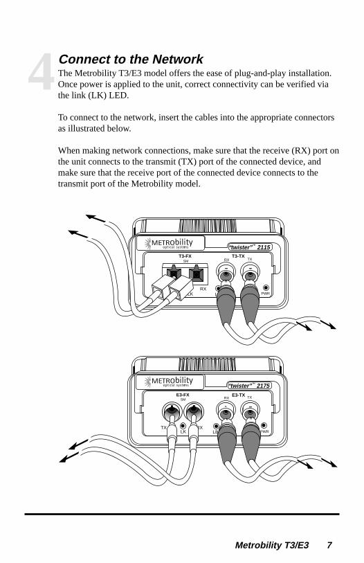
Connect to the NetworkThe Metrobility T3/E3 model offers the ease of plug-and-play installation.Once power is applied to the unit, correct connectivity can be verified viathe link (LK) LED.
To connect to the network, insert the cables into the appropriate connectorsas illustrated below.
When making network connections, make sure that the receive (RX) port onthe unit connects to the transmit (TX) port of the connected device, andmake sure that the receive port of the connected device connects to thetransmit port of the Metrobility model.
4
SME3-FX E3-TX
T3-FX T3-TX
LK LK PWRLBK
“twister”™ 2175
“twister”™ 2115
RXTX
LBK
SM
RX
LK PWRLBK MAN
LK
LK
TXRX
TXRX
8 Installation Guide
Coaxial InterfaceThe coaxial interface provides two BNC connectors. The receive port islabeled RX and the transmit port is labeled TX. Each connector supports amaximum segment length of 1200 feet. Use only RG-59 cables.
Fiber Optic Interface2115-23-01, 2115-25-01, 2175-23-01 and 2175-25-01: The fiber opticmultimode (MM) interface supports a maximum segment length of 2km forremote links.
2115-24-01, 2115-26-01, 2175-24-01 and 2175-26-01: The singlemode(SM) connector supports a maximum segment length of 15km.
2115-27-01 and 2175-27-01: The singlemode long haul interface supports amaximum segment of 40km.
2115-2J-01 and 2175-2J-01: The singlemode extended long haul interfacesupports a maximum segment length of 100km.
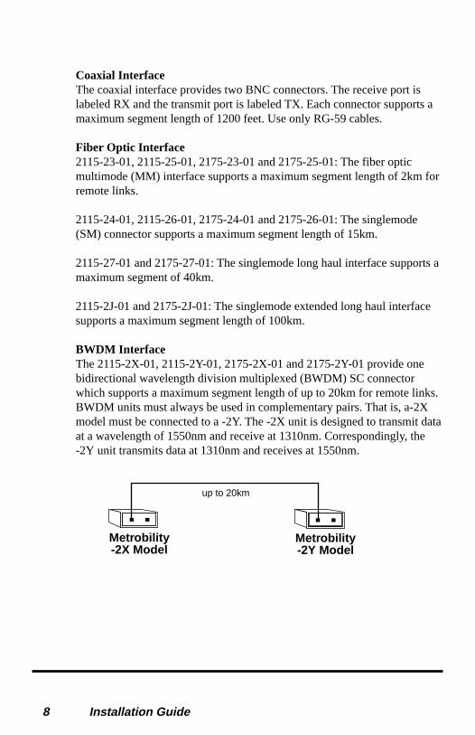
BWDM InterfaceThe 2115-2X-01, 2115-2Y-01, 2175-2X-01 and 2175-2Y-01 provide onebidirectional wavelength division multiplexed (BWDM) SC connectorwhich supports a maximum segment length of up to 20km for remote links.BWDM units must always be used in complementary pairs. That is, a-2Xmodel must be connected to a -2Y. The -2X unit is designed to transmit dataat a wavelength of 1550nm and receive at 1310nm. Correspondingly, the-2Y unit transmits data at 1310nm and receives at 1550nm.
Metrobility-2X Model
Metrobility-2Y Model
up to 20km

Metrobility T3/E3 9
5Apply PowerPower is provided through the desktop power supply module. This powermodule is equipped with an S760 hollow-type plug for insertion into the DCjack located on the back of the unit and a standard IEC 320-type AC powerreceptacle.
When making power connections, it is recommended that the DC powercord be connected to the DC input jack located on the back of the mediaconverter before making the AC connection to the outlet. Seat the powercord into the strain relief clip to ensure against accidental disconnection.
Upon receiving power, the media converter goes into normal operationmode and automatically provides the appropriate signal translation betweenthe connected network segments.
Verify correct segment connectivity via the LK LEDs on the front panel.
PWR
DC INPUT/5VDC
Strain Relief Clip
ON
OFF
LBO
CLPFLP
If an additional extension cord is used to connect the power module to thepower source, the following guidelines must be followed.
While one end of the AC power cord can be fitted with whatever plug isstandard for the country of operation, the end that connects to the powersupply module must have a female plug that fits this type of ACreceptacle.

10 Installation Guide
• AC 115V (North American): use a UL-listed and CSA-certified cordset consisting of a minimum 18 AWG, type SVT or SJT three-conductor cord, a maximum of 15 feet in length and a parallel blade,grounding-type attachment plug rated 15A, 125V.
• AC 230V (USA): use a UL-listed cord set consisting of a minimumNo. 18 AWG, type SVT three-conductor cord, a maximum of 15 feetin length and a Tandem blade grounding-type attachment plug rated15A, 250V.
• 240V (outside USA): use a cord set consisting of a minimum No. 18AWG cord and grounding-type attachment plug rated 15A, 250V.The cord set should have the appropriate safety approvals for thecountry in which the unit is being installed and marked HAR.

Metrobility T3/E3 11
User GuideThis section contains more detailed information regarding the operating featuresof the Metrobility T3/E3 media converter.
LED IndicatorsThe Metrobility T3/E3 media converter provides several LEDs on the front panel forthe visible verification of unit status and proper functionality. These LEDs can aid introubleshooting and overall network diagnosis and management.
DELmetsyS
DELlebaL
/roloCsutatS
noitacidnI
RWPneerG .rewopgniviecersitinU
FFO .deliafsahrorewopgniviecertonsitinU
sDELtroPreppoC
DELlebaL
/roloCsutatS
noitacidnI
KLneerG .tropeviecerreppocehtnotneserpsilangisA
FFO .tropehttadetcetedsilangisoN
KBLwolleY
ehtnosemarfgnimocnI.edomkcabpoolnisitropreppoCsiataD.eniltimsnartlaixaocehtnokcabtneseratropreppoc
.eniltimsnartcitporebifehthguorhttnesosla
FFO .noitarepolamron;tropreppocehtnodelbasidsikcabpooL
sDELtroPcitpOrebiF
DELlebaL
/roloCsutatS
noitacidnI
KLneerG .tropeviecercitporebifehtnotneserpsilangislacitponA
FFO .troprebifehttadetcetedsilangisoN
KBLwolleY
erakcolcdnaatadgnimocnI.edomkcabpoolnisitroprebiFtuodettimsnartoslasiataD.enilrebiftimsnartehtnokcabtnes
.eniltimsnartlaixaoceht
FFO .noitarepolamron;troprebifehtnodelbasidsikcabpooL

12 Installation Guide
Theory of Operation
Functional Block Diagram
Line Transformers
LineInterface
UnitFPGA
VCXO
Fiber Optic Circuit
RXCoaxial
TX
TXFiberRX
Coaxial to Fiber Data PathThe receive (RX) port on the coaxial interface accepts an electrical signal. Thissignal is coupled to the line interface unit (LIU) through a line transformer. The LIUperforms clock and data recovery and converts the signal into non-return to zero(NRZ) data and clock. The NRZ data and clock then pass through the field-program-mable gate array (FPGA), which encodes the data for fiber optic transmission. Theencoding ensures adequate transition density for reliable clock recovery at the remoteT3/E3 fiber optic interface.
Fiber to Coaxial Data PathThe RX port on the fiber interface accepts an optical signal from the remote T3/E3unit and converts it back to an electrical signal. The optical signal first enters thevoltage-controlled crystal oscillator (VCXO), which extracts the line rate clock anddata. The recovered clock and data are then sent to the FPGA for decoding. Thedecoded data stream goes to the LIU for encoding into T3 or E3 signals. Thetransmitted signal is coupled to the BNC coaxial connector through a line trans-former.
On both the RX and TX ports of the coaxial interface, surge protection is provided.
Timing PathsThe transmit (TX) and receive (RX) paths are clocked independently and duringnormal operation, the Metrobility T3/E3 units are never timing masters of thenetwork system. In the coaxial to fiber path, timing is recovered by the unit’s LIUand transmitted over the fiber line to the remote T3/E3 unit. In the fiber to coaxialpath, timing is derived from the incoming optical signal and sent over the coaxial TXline.

Metrobility T3/E3 13
LocalT3/E3Unit
RemoteT3/E3Unit
Coaxial CoaxialFiber
A
F
CB
E D
The following table describes how timing is affected if a failure occurs at variouspoints in the network.
eruliaFeniLtnioP
tluseR
AOXCVs'reviecerrebifehT.langisfossolstcetedtinu3E/3TlacolehT
.Bknilrebifrevonoissimsnartrofecruosgnimitehtsemoceb
BehT.tupnikcolcecnereferstiotstreverOXCVs'tinu3E/3TetomerehT
.retsamgnimitmetsysehtsemocebtinu3E/3Tetomer
C
,gnimitdepoolstroppustinu3E/3TetomerehtotdetcennoctnempiuqeehtfI.langisfossolstcetedtinehwkcolclanretnistiottreverdluohstnempiuqeeht
dna,kcolcrolangisdilavaedivorpotliafdluoctnempiuqeeht,ylevitanretlA.Dtnioptaderruccoeruliafehtfisaevaheblliwmetsyseht
DOXCVs'reviecerrebifehT.langisfossolstcetedUILs'tinu3E/3TetomerehT
.Eknilrebifrevonoissimsnartrofecruosgnimitehtsemoceb
ElacolehT.tupnikcolcecnereferstiotstreverOXCVs'tinu3E/3TlacolehT
.retsamgnimitmetsysehtsemocebtinu3E/3T
F3E/3TlacolehtotdetcennocecivedehT.srucconoitpursidgnimitmetsysoN
.langisfossolstcetedtinu
Data TransparencyThe Metrobility T3/E3 media converter offers full data transparency. Any codes orcommands contained within the data stream are passed through to the remote device.The only commands executed by the Metrobility converter are those set through theDIP switches.

14 User Guide
Link Loss IndicationsThe following examples show the status of the LK LED under various link condi-tions and describe when unframed all ones are generated. (Loopback is disabled inthese examples.)
Note: An all-ones pattern indicates an alarm indication signal (AIS) for the E3 unitsonly. For T3 models, the all-ones pattern is simply transmitted to the remote device;it does NOT indicate AIS.
NormalThe diagram below shows a typical configuration with good link status.
RemoteDevice
LocalDevice
Local T3/E3Unit
Remote T3/E3Unit
green LED unlit LED
Coax CoaxFiberLK
LK
LK
LK
Input Coaxial Link LossLoss of the copper input disables the BNC port’s LK LED. It also forces the T3/E3unit to generate unframed all ones (AIS for E3 only), which are transmitted out itsfiber port. For example, if the local unit’s inbound coaxial cable breaks, it willtransmit all ones to the remote T3/E3 unit via the fiber cable. The remote unit thencarries the pattern forward via its coaxial cable to the remote device.
RemoteDevice
LocalDevice
Local T3/E3Unit
Remote T3/E3Unit
green LED unlit LED
Coax CoaxFiberLK
LK
LK
LK
All Ones All Ones
All Ones carried forward
Input Fiber Link LossLoss of the fiber input is indicated by the fiber port’s unlit LK LED. When the fiberinput is lost, an unframed all-ones pattern is transmitted from the coaxial port, asshown in the following illustration.

Metrobility T3/E3 15
RemoteDevice
LocalDevice
Local T3/E3Unit
Remote T3/E3Unit
green LED unlit LED
Coax CoaxFiberLK
LK
LK
LKAll Ones
Remote Coaxial Link LossLoss of link to the remote device produces a red alarm condition at the remote siteand should force the device to revert to its internal clock. If the remote device isconfigured to send back a yellow alarm under this condition, the two T3/E3 unitswill carry the alarm forward to the local device, as shown below.
RemoteDevice
LocalDevice
Local T3/E3Unit
Remote T3/E3Unit
green LED unlit LED
Coax CoaxFiberLK
LK
LK
LKAIS AIS
AIS carried forward
AIS

16 User Guide
Loopback ModesThe Metrobility T3/E3 media converter features two loopback modes to help verifycorrect installation and to diagnose system problems.
NormalDuring normal operation, without loopback, data from a local device (CSU, PBX,etc.) enters the local T3/E3 unit’s coaxial receiver, passes through the fiber linebetween the two converters, then exits the remote unit’s coaxial transmitter to enterthe remote equipment, and vice versa.
Local T3/E3Unit
Remote T3/E3Unit
Coax CoaxFiber
LocalDevice
RemoteDevice
LoopbackLoopback helps to isolate and identify traffic problems within a specific segment.During loopback, the yellow LBK LED is lit. Loopback is enabled/disabled bysetting DIP switch 2 or 3. Once loopback is enabled, the unit will remain in thismode until the DIP switch is turned off.
Copper and fiber loopback cannot be enabled at the same time. If both DIP switchesare enabled, only the first one set will be in effect until it is disabled.
Copper LoopbackDuring copper loopback, timing and data received on the coaxial line are loopedback to the sending device. The loop occurs in the FPGA. The data is alsotransmitted to the remote T3/E3 converter, but the data from the remote unit isignored by the converter in loopback mode.
In the example shown below, the local T3/E3 unit has copper loopback enabled.Data received at the BNC port is simultaneously returned to the local device andsent to the remote T3/E3 unit and on to the remote device. Data from the remotedevice is transmitted by the remote unit, however, it is ignored by the local unitat its fiber optic interface.
Local T3/E3 Unitwith Copper Loopback
Remote T3/E3Unit
Coax CoaxFiber
LocalDevice
RemoteDevice
X

Metrobility T3/E3 17
Fiber LoopbackIn this mode, the incoming data and clock on the fiber line are looped back. Theloop occurs in the FPGA. The data is still sent out the coaxial transmitter.However, the data received at the BNC interface is ignored.
In the example below, the remote T3/E3 unit has fiber loopback enabled. Datareceived at the fiber optic input is simultaneously returned to the local deviceand sent to the remote device. However, data from the remote device is ignoredby the remote T3/E3 unit at its coaxial interface.
Local T3/E3Unit
Remote T3/E3 Unitwith Fiber Loopback
Coax CoaxFiber
LocalDevice
RemoteDevice
X
18 User Guide
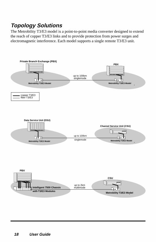
Topology SolutionsThe Metrobility T3/E3 model is a point-to-point media converter designed to extendthe reach of copper T3/E3 links and to provide protection from power surges andelectromagnetic interference. Each model supports a single remote T3/E3 unit.
fiber T3/E3copper T3/E3
up to 100kmsinglemode
Private Branch Exchange (PBX)PBX
Metrobility T3/E3 Model Metrobility T3/E3 Model
up to 100km
singlemode
Data Service Unit (DSU)
Channel Service Unit (CSU)
Metrobility T3/E3 ModelMetrobility T3/E3 Model
Intelligent 7500 Chassis
with T3/E3 Modules
up to 2kmmultimode
PBX
CSU
Metrobility T3/E3 Model

Metrobility T3/E3 19
Technical Specifications
Network ConnectionsCoaxial InterfaceConnector ______________________________________________ BNC receptacleImpedance____________________________________________________ 75 ohmsSignal Structure ________________________________ ANSI T1.404, T1404a (T3)
_________________________________________ ITU G.703 (E3)Supported Link Length ______________________________________ up to 1200 ftCable Type _________________________________________ RG-59 coaxial cable
Multimode Fiber Optic InterfaceConnector ___________________________________________________ ST or SCWavelength ___________________________________________________ 1310 nmRX Input Sensitivity _______________________________ -31 dBm peak minimumOutput Power __________________________ -20 dBm to -14 dBm (62.5/125 µm)Supported Link Length _______________________________ up to 2km full duplexCable Type _____________________________________ 50/125, 62.5/125 µm F/O
Singlemode Fiber Optic InterfaceConnector ___________________________________________________ ST or SCWavelength ___________________________________________________ 1310 nmRX Input Sensitivity _______________________________ -31 dBm peak minimumOutput Power ______________________________ -15 dBm to -8 dBm (9/125 µm)Supported Link Length ______________________________ up to 15km full duplexCable Type __________________________ 8.3/125, 8.7/125, 9/125, 10/125 µm F/O
Singlemode Fiber Optic Interface — long haul distance supportConnector ________________________________________________________ SCWavelength ___________________________________________________ 1310 nmRX Input Sensitivity ___________________________________ -35 dBm minimumOutput Power ________________________________ -5 dBm to 0 dBm (9/125 µm)Supported Link Length ______________________________ up to 40km full duplexCable Type __________________________ 8.3/125, 8.7/125, 9/125, 10/125 µm F/O

20 User Guide
Singlemode Fiber Optic Interface — extended long haul distance supportConnector ________________________________________________________ SCWavelength ___________________________________________________ 1550 nmRX Input Sensitivity ___________________________________ -37 dBm minimumOutput Power _______________________________ -3.0 dBm to 0 dBm (9/125 µm)Supported Link Length _____________________________ up to 100km full duplexCable Type __________________________ 8.3/125, 8.7/125, 9/125, 10/125 µm F/O
Singlemode BWDM Fiber Optic InterfaceConnector ________________________________________________________ SCSupported Link Length ______________________________ up to 20km full duplexCable Type ______________________________________________ 9/125 µm F/O(2115-2X-01, 2175-2X-01)
TX Wavelength ______________________________________________ 1550nmRX Wavelength ______________________________________________ 1310nmRX Input Sensitivity _________________________________ -32 dBm minimumOutput Power ____________________________ -8 dBm to -15 dBm (9/125 µm)
(2115-2Y-01, 2175-2Y-01)TX Wavelength ______________________________________________ 1310nmRX Wavelength ______________________________________________ 1550nmRX Input Sensitivity _________________________________ -32 dBm minimumOutput Power ____________________________ -8 dBm to -15 dBm (9/125 µm)
Data RateData Rate _____________________________ 44.736Mbps (T3); 34.368Mbps (E3)
PowerInput _____________________________________ +5.0VDC @ 0.4A, 2W average
EnvironmentalOperating Temperature ________________________________________ 0° to 55° CStorage Temperature ________________________________________ -30° to 70° CRelative Humidity ______________________________5% to 95% non-condensingPhysical Case _____________________________ Fully enclosed metal constructionDimensions ____________________________________ 4.38"L x 3.26"W x 1.71"H
____________________________________ 12.3 cm x 8.3 cm x 4.3 cmWeight (including power supply) _______________________________ 3 lb, 1.36 kg

Metrobility T3/E3 21
Acronyms and AbbreviationsThis list defines the acronyms and abbreviations used in this guide.
AIS Alarm Indication SignalANSI American National Standards InstituteAWG American Wire GaugeB3ZS Bipolar Three Zeroes Substitution T3 line codingBNC Bayonet-Neill-Concelman connector
BWDM Bidirectional Wavelength Division MultiplexedCLP Copper LoopbackCSA Canadian Standards AssociationCSU Channel Service UnitDSU Data Service Unit
E3 34.368 Mbps communications standardF/O Fiber OpticFLP Fiber Loopback
FPGA Field-Programmable Gate ArrayHDB3 High Density Bipolar Three Zeroes Substitution E3 line coding
IEC International Electrotechnical CommissionITU International Telecommunications Union
LBK LoopbackLBO Line Build OutLIU Line Interface UnitLK Link
Mbps Megabits per secondMM Multimode
MTBF Mean Time Between FailuresNRZ Non-Return to Zero line codingPBX Private Branch Exchange
PWR PowerRX ReceiveSM SinglemodeT3 44.736 Mbps communications standardTX TransmitUL Underwriters Laboratories
VCXO Voltage-controlled crystal oscillator

22 User Guide
Product Safety, EMC and Compliance StatementsThis equipment complies with the following requirements:
• UL • ITU-G.703• CSA • G.704• EN60950 (safety) • G.706• FCC Part 15, Class A • ANSI T1.403-1999• EN55022 Class A (emissions) • ANSI T1.408• EN55024: 1998 (immunity) • Class 1 Laser Product• IEC 825-1 Classification • DOC Class A (emissions)
This product shall be handled, stored and disposed of in accordance with all govern-ing and applicable safety and environmental regulatory agency requirements.
The following FCC and Industry Canada compliance information is applicable toNorth American customers only.
USA FCC Radio Frequency Interference StatementThis equipment has been tested and found to comply with the limits for a Class Adigital device, pursuant to Part 15 of the FCC Rules. These limits are designed toprovide reasonable protection against harmful interference when the equipment isoperated in a commercial environment. This equipment generates, uses and canradiate radio frequency energy, and if not installed and used in accordance with theinstruction manual, may cause harmful interference to radio communications.Operation of this equipment in a residential area is likely to cause harmful interfer-ence in which case the user will be required to correct the interference at his ownexpense.
Caution: Changes or modifications to this equipment not expressly approved by theparty responsible for compliance could void the user’s authority to operate theequipment.
Canadian Radio Frequency Interference StatementThis Class A digital apparatus meets all requirements of the Canadian Interference-Causing Equipment Regulations.
Cet appareil numérique de la classe A respecte toutes les exigences du Réglement surle matériel brouilleur du Canada.
Metrobility T3/E3 23
Warranty and ServicingThree-Year Warranty for the Metrobility T3/E3 ModelMetrobility Optical Systems, Inc. warrants that every Metrobility T3/E3 model willbe free from defects in material and workmanship for a period of THREE YEARS.This warranty covers the original user only and is not transferable. Should the unitfail at any time during this warranty period, Metrobility will, at its sole discretion,replace, repair, or refund the purchase price of the product. This warranty is limitedto defects in workmanship and materials and does not cover damage from accident,acts of God, neglect, contamination, misuse or abnormal conditions of operation orhandling, including overvoltage failures caused by use outside of the product’sspecified rating, or normal wear and tear of mechanical components.
To establish original ownership and provide date of purchase, complete and returnthe registration card or register the product online at www.metrobility.com. Ifproduct was not purchased directly from Metrobility, please provide source, invoicenumber and date of purchase.
To return a defective product for warranty coverage, contact Metrobility CustomerService for a return materials authorization (RMA) number. Send the defectiveproduct postage and insurance prepaid to the address provided to you by the Metro-bility Technical Support Representative. Failure to properly protect the productduring shipping may void this warranty. The Metrobility RMA number must beclearly on the outside of the carton to ensure its acceptance.
Metrobility will pay return transportation for product repaired or replaced in-warranty. Before making any repair not covered by the warranty, Metrobility willestimate cost and obtain authorization, then invoice for repair and return transporta-tion. Metrobility reserves the right to charge for all testing and shipping costsincurred, if test results determine that the unit is without defect.
This warranty constitutes the buyer’s sole remedy. No other warranties, such asfitness for a particular purpose, are expressed or implied. Under no circumstanceswill Metrobility be liable for any damages incurred by the use of this productincluding, but not limited to, lost profits, lost savings, and incidental or consequentialdamages arising from the use of, or inability to use, this product. Authorized resellersare not authorized to extend any other warranty on Metrobility’s behalf.

Product ManualsThe most recent version of this manual is available online at
http://www.metrobility.com/support/manuals.htm
To obtain additional copies of this manual, contact your reseller, or call1.877.526.2278 or 1.603.880.1833
Product RegistrationTo register your product, go to
http://www.metrobility.com/support/registration.cfm
25 Manchester Street, Merrimack, NH 03054 USAtel: 1.603.880.1833 • fax: 1.603.594.2887
www.metrobility.com
5660-000042 B9/02