t300e english operator manual (na) - system clean...
TRANSCRIPT

T300e
9014506Rev. 00 (03-2015)
Automatic Floor Scrubber
*9014506*
For the latest Parts manuals and otherlanguage Operator manuals, visit:
www.tennantco.com/manuals
Hygenic Fully Cleanable Recovery TankTennantTrue Parts
English EN
Operator Manual
North America / International

2 Tennant T300e (03- 2015)
INTRODUCTION
This manual is furnished with each new model.It provides necessary operation and maintenanceinstructions.
Read this manual completely andunderstand the machine beforeoperating or servicing it.
This machine will provide excellent service. However,the best results will be obtained at minimum costs if:
S The machine is operated with reasonable care.
S The machine is maintained regularly - per themaintenance instructions provided.
S The machine is maintained with manufacturersupplied or equivalent parts.
To view, print or download manuals online visitwww.tennantco.com/manuals
PROTECT THE ENVIRONMENTPlease dispose of packaging materialsand used machine components suchas batteries in an environmentally safeway according to your local wastedisposal regulations.
Always remember to recycle.
Tennant CompanyPO Box 1452Minneapolis, MN 55440Phone: (800) 553- 8033 or (763) 513- 2850
www.tennantco.com
Trojan and HydroLINK are registered trademarks of Trojan Battery Company.
Specifications and parts are subject to change without notice.
Original Instructions. Copyright E2015 Tennant Company.All rights reserved.
INTENDED USE
The automatic floor scrubber is intended forcommercial use, for example in hotels, schools,hospitals, factories, shops, offices and rentalbusinesses. It is designed to scrub hard floor surfaces(concrete, tile, stone, synthetic, etc.) in an indoorenvironment. Do not use this machine on carpetedsurfaces. Use only recommended pads/brushes andcommercially available floor cleaning detergents. Donot use this machine other than described in thisOperator Manual.
MACHINE DATA
Please fill out at time of installationfor future reference.
Model No. -
Serial No. -
Installation Date -
UNCRATING MACHINE
Carefully check machine for signs of damage. Reportdamages at once to carrier. Contact distributor orTennant for missing items.
To uncrate the machine, remove straps, wheel blocksand shipping brackets. Using the supplied rampcarefully back the machine off the pallet. Make surescrub head is in the raised position.
ATTENTION: Do not remove machine from palletwithout using ramp, machine damage may occur.

Tennant T300e (03- 2015) 3
TABLE OF CONTENTS
OPERATIONIMPORTANT SAFETY INSTRUCTIONS 4. . . . . . .
SAFETY LABELS 6. . . . . . . . . . . . . . . . . . . . . . . . . . .
MACHINE COMPONENTS 7. . . . . . . . . . . . . . . . . . .
MACHINE SYMBOLS 8. . . . . . . . . . . . . . . . . . . . . . .
CONTROL PANEL COMPONENTS 8. . . . . . . . . . .
INSTALLING BATTERIES 9. . . . . . . . . . . . . . . . . . .BATTERY PACK LIFT- OUT TRAY (Option) 9.
HOW THE MACHINE WORKS 10. . . . . . . . . . . . . . .
BRUSH AND PAD INFORMATION 10. . . . . . . . . . . .
MACHINE SETUP 11. . . . . . . . . . . . . . . . . . . . . . . . . .ATTACHING SQUEEGEE ASSEMBLY 11. . . . .INSTALLING BRUSH/PAD - 3 Lug Disk 11. . . .INSTALLING BRUSH/PAD -Insta- Click Magnetic Disk (Option) 12. . . . . . . .INSTALLING PAD - Orbital 13. . . . . . . . . . . . . . .INSTALLING CYLINDRICAL BRUSHES 13. . . .FILLING SOLUTION TANK 14. . . . . . . . . . . . . . .ec-H2O NanoClean WATER CONDITIONINGCARTRIDGE (ec-H2O model) 15. . . . . . . . . . . .ACCESSORY RAILS 15. . . . . . . . . . . . . . . . . . . . .
MACHINE OPERATION 16. . . . . . . . . . . . . . . . . . . . .PRE-OPERATION CHECK LIST 16. . . . . . . . . . .OPERATING MACHINE 16. . . . . . . . . . . . . . . . . .WHILE OPERATING MACHINE 18. . . . . . . . . . .EMERGENCY SHUT-OFF BUTTON 19. . . . . . .BATTERY DISCHARGE INDICATOR 19. . . . . . .CIRCUIT BREAKER PANEL 19. . . . . . . . . . . . . .HOUR METER 19. . . . . . . . . . . . . . . . . . . . . . . . . .
DRAINING TANKS 20. . . . . . . . . . . . . . . . . . . . . . . . . .DRAINING RECOVERY TANK 20. . . . . . . . . . . .DRAINING SOLUTION TANK 20. . . . . . . . . . . . .
SERVICE INDICATOR CODES 21. . . . . . . . . . . . . . .
MAINTENANCEMAINTENANCE CHART 24. . . . . . . . . . . . . . . . . . . . .
MACHINE MAINTENANCE 25. . . . . . . . . . . . . . . . . .AFTER DAILY USE 25. . . . . . . . . . . . . . . . . . . . . .AFTER WEEKLY USE 26. . . . . . . . . . . . . . . . . . .AFTER EVERY 50 HOURS OF USE 27. . . . . . .AFTER EVERY 100 HOURS OF USE 27. . . . . .ELECTRIC MOTORS 27. . . . . . . . . . . . . . . . . . . .BELTS 28. . . . . . . . . . . . . . . . . . . . . . . . . . . . . . . . .ORBITAL SCRUB HEAD ISOLATORS 28. . . . . .
BATTERIES 28. . . . . . . . . . . . . . . . . . . . . . . . . . . . . . . .MAINTENANCE-FREE BATTERIES 28. . . . . . .FLOODED (WET) LEAD-ACID BATTERIES 28.CHECKING CONNECTIONS / CLEANING 29. .CHARGING BATTERIES 29. . . . . . . . . . . . . . . . .BATTERY CHARGER SETTINGS 30. . . . . . . . .HYDROLINK BATTERY WATERINGSYSTEM 32. . . . . . . . . . . . . . . . . . . . . . . . . . . . . . .
SQUEEGEE BLADE REPLACEMENT 33. . . . . . . . .
ec-H2O NanoClean WATER CONDITIONINGCARTRIDGE REPLACEMENT 34. . . . . . . . . . . . . . .
LOADING/UNLOADING MACHINE FORTRANSPORTING 35. . . . . . . . . . . . . . . . . . . . . . . . . .
STORING MACHINE 35. . . . . . . . . . . . . . . . . . . . . . . .Freeze Protection 35. . . . . . . . . . . . . . . . . . . . . . . .
TROUBLESHOOTING 36. . . . . . . . . . . . . . . . . . . . . . .
SPECIFICATIONSGENERAL MACHINEDIMENSIONS/CAPACITIES/PERFORMANCE 38. .
MACHINE DIMENSIONS 40. . . . . . . . . . . . . . . . . . . .

OPERATION
4 Tennant T300e (03- 2015)
IMPORTANT SAFETY INSTRUCTIONS - SAVE THESE INSTRUCTIONS
The following warning precautions are used throughoutthis manual as indicated in their description:
WARNING: To warn of hazards or unsafepractices which could result in severe personalinjury or death.
FOR SAFETY: To identify actions which must befollowed for safe operation of equipment.
The following information signals potentiallydangerous conditions to the operator. Know whenthese conditions can exist. Locate all safety devices onthe machine. Report machine damage or faultyoperation immediately.
WARNING: To Reduce the Risk of Fire,Explosion, Electric Shock or Injury:
- Read manual before operating machine.
- Do not use or pick up flammable materials.
- Do not use near flammable liquids, vapors orcombustible dusts.This machine is not equipped with anexplosion proof motor. The electric motor willspark upon start up and during operationwhich could cause a flash fire or explosion ifmachine is used in an area where flammablevapors/liquids or combustible dusts arepresent.
- Batteries emit hydrogen gas. Explosion or firecan result. Keep sparks and open flame awaywhen charging.
- Disconnect battery cables and charger cordbefore cleaning and servicing machine.
- Do not charge batteries with damaged cord. Donot modify plug.
If the charger supply cord is damaged orbroken, it must be replaced by themanufacturer or its service agent or a similarlyqualified person in order to avoid a hazard.
- Do not use outdoors. Store indoors.
- Spinning pad/brush, keep hands away.
WARNING: Magnetic Field Hazard. Magneticpad driver/brush can be harmful to pacemakerwearers or medical implants.
FOR SAFETY:
1. Do not operate machine:- Unless trained and authorized.- Unless operator manual is read and
understood.- Unless mentally and physically capable of
following machine instructions.- Under the influence of alcohol or drugs.- While using a cell phone or other types of
electronic devices.- If not in proper operating condition.- In outdoor areas. This machine is for
indoor use only.- In areas where flammable vapors/liquids or
combustible dusts are present.- With pads or accessories not supplied or
approved by Tennant. The use of otherpads may impair safety.
- In areas with possible falling objects.- In areas that are too dark to safely see the
controls or operate machine.
2. Before operating machine:- Check machine for fluid leaks.- Make sure all safety devices are in place
and operate properly.
3. When operating machine:- Use only as described in this manual.- Report machine damage or faulty operation
immediately.- Wear closed- toe, non- slip work shoes.- Reduce speed when turning.- Go slowly on inclines and slippery
surfaces.- Do not scrub on inclines that exceed 9%
grade or transport on inclines that exceed21% grade.
- Follow site safety guidelines concerningwet floors.
- Follow mixing, handling and disposalinstructions on chemical containers.
- Do not carry passengers on machine.- Use care when reversing machine.- Keep children and unauthorized persons
away from machine.- Do not allow machine to be used as a toy.

OPERATION
Tennant T300e (03- 2015) 5
4. Before leaving or servicing machine:- Stop on level surface.- Set the parking brake, if equipped.- Turn off machine and remove key.
5. When servicing machine:- Disconnect battery connection and charger
cord before working on machine.- All work must be done with sufficient
lighting and visibility.- All repairs must be performed by trained
personnel.- Use Tennant supplied or approved
replacement parts.- Do not modify the machine from its original
design.- Do not jack up machine.- Avoid moving parts. Do not wear loose
clothing or jewelry and secure long hair.- Do not disconnect the off- board charger’s
DC cord from the machine’s receptaclewhen the charger is operating. Arcing mayresult. If the charger must be interruptedduring charging cycle, disconnect the ACpower supply cord first.
- Do not use incompatible battery chargersas this may damage battery packs andpotentially cause a fire hazard.
- Inspect charger cord regularly for damage.- Keep work area well ventilated.- Avoid contact with battery acid.- Keep all metal objects off batteries.- Do not power spray or hose off machine.- Use a hoist or adequate assistance when
lifting batteries.- Battery installation must be done by trained
personnel.- Wear personal protection equipment as
needed and where recommended in thismanual.
For Safety: wear protective gloves.
For Safety: wear eye protection.
6. When loading/unloading machine onto/offtruck or trailer:- Drain tanks before loading machine.- Use a ramp, truck or trailer that can support
the machine weight and operator.- Do not operate the machine on a ramp
incline that exceeds a 21% grade level.- Use a winch if ramp incline exceeds a 21%
grade level.- Lower the scrub head and squeegee before
tying down machine.- Turn machine off and remove key.- Set parking brake (if equipped).- Block machine wheels.- Use tie- down straps to secure machine.

OPERATION
6 Tennant T300e (03- 2015)
SAFETY LABELS
The safety labels appear on the machine in the locations indicated. Replace labels if they are missing or becomedamaged or illegible.
WARNING LABEL - Located on recovery tank cover.
WARNING LABEL -Electrical hazard.Disconnect batterycables before servicingmachine.Located on circuit breakerpanel.
WARNING LABEL -Batteries emithydrogen gas.Explosion or fire canresult. Keep sparksand open flame awaywhen charging.Located on bottom sideof recovery tank.
WARNING LABEL -Spinning pad. Keep hands away.Located on disk scrub head model.
WARNING LABEL -Spinning brush. Keep hands away.Located on cylindrical scrub headmodel.
WARNING LABEL -Magnetic Field Hazard. Magneticpad driver/brush can be harmfulto pacemaker wearers or medicalimplants.Located on Click-Quick magneticpad driver/brush.
OPERATION
Tennant T300e (03- 2015) 7
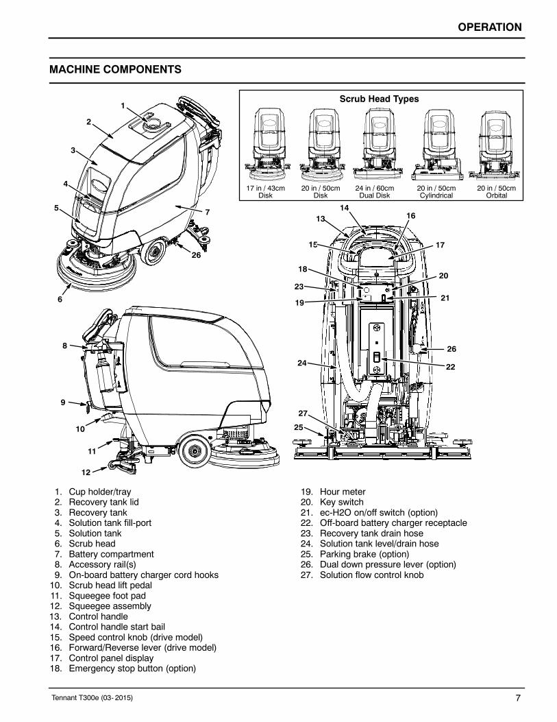
MACHINE COMPONENTS
15
1
17 in / 43cmDisk
20 in / 50cmDisk
24 in / 60cmDual Disk
20 in / 50cmCylindrical
20 in / 50cmOrbital
Scrub Head Types
2
4
3
5
6
7
26
8
9
10
11
12
1416
17
20
2123
18
19
24
25
27
26
22
13
1. Cup holder/tray2. Recovery tank lid3. Recovery tank4. Solution tank fill-port5. Solution tank6. Scrub head7. Battery compartment8. Accessory rail(s)9. On-board battery charger cord hooks10. Scrub head lift pedal11. Squeegee foot pad12. Squeegee assembly13. Control handle14. Control handle start bail15. Speed control knob (drive model)16. Forward/Reverse lever (drive model)17. Control panel display18. Emergency stop button (option)
19. Hour meter20. Key switch21. ec-H2O on/off switch (option)22. Off-board battery charger receptacle23. Recovery tank drain hose24. Solution tank level/drain hose25. Parking brake (option)26. Dual down pressure lever (option)27. Solution flow control knob

OPERATION
8 Tennant T300e (03- 2015)
MACHINE SYMBOLS
Solution flow
ec-H2O scrubbing (option)
Circuit breaker
Do not lift by accessory rails
No step
Dual down pressure
No detergent (ec-H2O option)
Water temperature (ec-H2O option)
Battery charge
Fast speed (drive model)
Slow speed (drive model)
Parking brake (option)
Forward / Reverse (drive model)
On
Off
No Solution flow
CONTROL PANEL COMPONENTS
31 2 4
1. Service indicator - Lights up when a machine orcharger fault is detected.
2. Parking brake indicator (option) - Lights upwhen parking brake lever is engaged. To turn offindicator, disengage parking brake lever near leftrear wheel.
3. Battery discharge indicator (BDI) - The batterydischarge indicator serves two functions. In normalscrub mode it displays the charge level of thebatteries. It also, in conjunction when the serviceindicator is flashing, provides specific LED codeswhen a machine or charger fault is detected.
4. ec-H2O indicator (Option) - Lights up blue whenec-H2O system is activated and operatingnormally.

OPERATION
Tennant T300e (03- 2015) 9
INSTALLING BATTERIES
WARNING: Batteries emit hydrogen gas.Explosion or fire can result. Keep sparks and openflame away when charging.
FOR SAFETY: When servicing machine, wearappropriate personal protection equipment asneeded. Avoid contact with battery acid.
BATTERY SPECIFICATIONSTwo 12 volt deep-cycle batteries.
Contact distributor or Tennant for batteryrecommendations.FOR SAFETY: Before leaving or servicing machine,stop on level surface, turn off machine, remove keyand set parking brake if equipped.
1. Lift the recovery tank to access the batterycompartment (Figure 1).
FIG. 1
2. With adequate assistance, carefully install thebatteries into the battery compartment. Arrange thebatteries as shown (Figure 2).
FOR SAFETY: When servicing machine, use a hoistor adequate assistance when lifting batteries.
3. Using the supplied battery post boots, connect thecables to the battery posts as shown (Figure 2).Connect the machine’s black (- ) battery cable last.Use insulated tools when working near batteries.
MachineFront
BLACK
RED
FIG. 2
IMPORTANT: Make sure that the machine’s batterycharger is properly set before charging. SeeBATTERY CHARGER SETTINGS.
BATTERY PACK LIFT-OUT TRAY (Option)Models equipped with the optional battery lift-out trayfor quick or frequent battery pack exchange.
FOR SAFETY: Before leaving or servicing machine,stop on level surface, turn off machine, remove keyand set parking brake if equipped.
WARNING: Batteries emit hydrogen gas.Explosion or fire can result. Keep sparks and openflame away when charging.
1. Disconnect the battery cable connection atmachine (Figure 3).
FIG. 3
FOR SAFETY: When servicing machine, wearappropriate personal protection equipment asneeded. Avoid contact with battery acid.
2. Using an approved lift strap that supports theweight of battery pack, connect the strap to the twolift brackets as shown. Using a lift hoist rated tohandle the weight of the battery pack, carefully liftthe battery packs to and from machine. Keep onehand on the battery lift-out tray when lifting forstability (Figure 4).
Before lifting battery pack, make sure the batteriesare secured to the battery lift- out tray with thesupplied battery strap as shown (Figure 4).
FIG. 4
3. Reconnect the battery cable connection afterinstalling battery pack.

OPERATION
10 Tennant T300e (03- 2015)
HOW THE MACHINE WORKS
Conventional scrubbing:When using the conventional scrubbing mode, waterand detergent mixture from the solution tank flows tothe floor and the rotating brush(es)/pad(s) scrub thefloor clean. As the machine moves forward, thesqueegee with vacuum suction picks up the dirtysolution from the floor into the recovery tank.
ec-H2O NanoClean Technology (option):When using the ec-H2O NanoClean technology, normalwater passes through a module where it is electricallyconverted into a cleaning solution. The electricallyconverted water attacks the dirt, allowing the machineto easily scrub away the suspended soil. The convertedwater then returns to normal water in the recovery tank.
BRUSH AND PAD INFORMATION
For best cleaning results use the appropriate brush orpad for your cleaning application. Listed below arebrushes and pads and the applications for which eachis best suited.
NOTE: The amount and type of soilage play animportant role in determining the type of brush or padto use. Contact a Tennant representative for specificrecommendations.
Soft nylon bristle scrub brush (White) -Recommended for cleaning coated floors withoutremoving finish. Cleans without scuffing.
Polypropylene bristle scrub brush (Black) -This general purpose polypropylene bristle scrub brushis used for scrubbing lightly compacted soilage. Thisbrush works well for maintaining concrete, wood andgrouted tile floors.
Super abrasive bristle scrub brush (Gray) -Nylon fiber impregnated with abrasive grit to removestains and soilage. Strong action on any surface.Performs well on buildup, grease, or tire marks.
Polishing pad (White) -Used to maintain highly polished or burnished floors.
Buffing pad (Red) - Used for light duty scrubbingwithout removing floor finish.
Scrubbing pad (Blue) - Used for medium toheavy-duty scrubbing. Removes dirt, spills, and scuffsand leaves surface clean ready for recoating.
Stripping pad (Brown) - Used for stripping of floorfinish to prepare the floor for recoating.
Heavy duty stripping pad (Black) - Used foraggressive stripping of heavy finishes/sealers, or veryheavy duty scrubbing.
Surface preparation pad (Maroon) - Used for veryaggressive chemical free removal of floor finish toprepare the floor for re-coating

OPERATION
Tennant T300e (03- 2015) 11
MACHINE SETUP
ATTACHING SQUEEGEE ASSEMBLY
FOR SAFETY: Before leaving or servicing machine,stop on level surface, turn off machine, remove keyand set parking brake if equipped.
1. Lift the squeegee mount bracket to the raisedposition. Place toe under pedal to lift (Figure 5).
FIG. 5
2. Mount the squeegee assembly to the squeegeemount bracket (Figure 6). Tighten knobs to securesqueegee assembly to bracket.
FIG. 6
3. Connect the vacuum hose to the squeegeeassembly (Figure 7).
FIG. 7
INSTALLING BRUSH/PAD - 3 Lug Disk
FOR SAFETY: Before leaving or servicing machine,stop on level surface, turn off machine, remove keyand set parking brake if equipped.
1. Step down on the scrub head lift pedal to raise thescrub head off the floor (Figure 8).
FIG. 8
2. Attach the pad to the pad driver before installingthe disk (Figure 9). Secure pad with centerlock.
FOR SAFETY: Do not operate machine with padsor accessories not supplied or approved byTennant. The use of other pads may impair safety.
FIG. 9
3. Single disk model - Position the three lugs into themotor hub slots and give the pad driver/brush aquick counter-clockwise turn to engage hub (Figure10). View through the scrub head window to alignlugs.
FIG. 10

OPERATION
12 Tennant T300e (03- 2015)
Dual disk model - Turn the brush motor hub untilthe lug slot with spring clip is visible. Position thethree lugs into the motor hub slots and give the paddriver/brush a quick turn towards the spring clip(Figure 11). View through the scrub head window toalign lugs.
NOTE: The left and right disks engage the hubs inopposite directions.
FIG. 11
4. Single disk model - To remove the paddriver/brush, press down on the plunger and turnthe pad driver/brush clockwise (Figure 12).
FIG. 12
Dual disk model - To remove the pad driver/brush,grip the disk and give it a quick turn in the directionas shown (Figure 13).
FIG. 13
INSTALLING BRUSH/PAD - Insta-Click MagneticDisk (Option)
FOR SAFETY: Before leaving or servicing machine,stop on level surface, turn off machine, remove keyand set parking brake if equipped.
WARNING: Magnetic Field Hazard. Magneticpad driver/brush can be harmful to pacemakerwearers or medical implants.
1. Step down on the scrub head lift pedal to raise thescrub head off the floor (Figure 14).
FIG. 14
2. Attach the pad to the pad driver before installingthe driver (Figure 15). Secure pad with centerlock.
FOR SAFETY: Do not operate machine with padsor accessories not supplied or approved byTennant. The use of other pads may impair safety.
FIG. 153. Place the pad driver/brush under the scrub head
and lift into position. The Insta-Click paddriver/brush will automatically click into position(Figure 16).
FIG. 16

OPERATION
Tennant T300e (03- 2015) 13
4. To remove the pad driver(s)/brush(es), raise thescrub head and press the yellow plunger buttonwith foot or hand (Figure 17). Pad will drop to floor.
FIG. 17
INSTALLING PAD - Orbital
For best cleaning performance and to avoid damagingthe pad driver plate or floor surface, always use backerpad with work pads (Figure 18).
Backer pad
Work pad
Scrub head
Pad driver plate
FIG. 18
FOR SAFETY: Before leaving or servicing machine,stop on level surface, turn off machine, remove keyand set parking brake if equipped.
1. Step down on the scrub head lift pedal to raise thescrub head off the floor (Figure 19).
FIG. 19
2. Install the backer pad, retaining strips facingoutward, to bottom of scrub head (Figure 20).Make sure pad is centered on scrub head.
FIG. 20
3. Attach the work pad to the backer pad (Figure 21).
FIG. 21
INSTALLING CYLINDRICAL BRUSHES
FOR SAFETY: Before leaving or servicing machine,stop on level surface, turn off machine, remove keyand set parking brake if equipped.
1. Step down on the scrub head lift pedal to raise thescrub head off the floor (Figure 22).
FIG. 22

OPERATION
14 Tennant T300e (03- 2015)
2. Remove the debris tray by sliding it out from thescrub head (Figure 23).
FIG. 233. Remove the idler plate from the scrub head by
unscrewing the yellow knob (Figure 24).
FIG. 244. Slide the brushes into the scrub head and connect
the slotted ends of each brush into the drive hubs(Figure 25).
FIG. 255. Connect the idler plate to the brush ends and
reattach the idler plate. Make sure the idler platehooks are engaged before tightening knob (Figure26).
FIG. 26
6. Replace debris tray.
FILLING SOLUTION TANK
FOR SAFETY: Before leaving or servicing machine,stop on level surface, turn off machine, remove keyand set parking brake if equipped.
Remove the solution tank lid and fill the solution tank.Stop filling tank when the level reaches the “3/3” markon the solution tank drain hose indicator (Figure 27).
ec-H2O Scrubbing - Only use cool clean water (lessthan 70F/21C). Do not use hot water or addconventional floor cleaning detergents. An ec-H2Osystem fault will occur if cleaning detergents are added.
Conventional Scrubbing - Use hot water(140F/60C maximum). Pour a recommendedcleaning detergent into the solution tank according tomixing instructions on the container.
NOTE: Do not use the ec-H2O system when there areconventional cleaning detergents in the solution tank.Drain, rinse, and refill the solution tank with clear coolwater before operating the ec-H2O system.
WARNING: Flammable materials can cause anexplosion or fire. Do not use flammable materialsin tank(s).
ATTENTION: For Conventional Scrubbing, only usecommercially approved cleaning detergents. Machinedamage due to improper detergent usage will void themanufacturer’s warranty.
FIG. 27
The solution tank fill- port is equipped with two hoseclips to hold hose while filling. The two clips aredifferent hose diameter sizes (Figure 28).
FIG. 28

OPERATION
Tennant T300e (03- 2015) 15
ec-H2O NanoClean WATER CONDITIONINGCARTRIDGE (ec-H2O model)
The ec-H2O system is equipped with a waterconditioning cartridge (Figure 29). The cartridge isdesigned to protect the machine’s plumbing systemfrom potential scaling.
The cartridge is required to be replaced when it reachesits maximum water usage or expiration time of when thecartridge was activated, which ever comes first.
Depending on machine usage a new cartridge can lastanywhere from 12 to 24 months.
The control panel will signal a code when it’s time toreplace cartridge. See SERVICE INDICATOR CODESfor further details.
FIG. 29
All cartridges are labeled with a manufacture date. Theshelf-life of an un-installed cartridge is one year frommanufacture date. For new cartridge replacement, theecH2O module timer must be reset. See ec-H2ONanoClean WATER CONDITIONING CARTRIDGEREPLACEMENT.
ATTENTION: During first time use and after replacingthe water conditioning cartridge, the ec-H2O systemwill automatically override the selected solution flowrate for up to 75 minutes.
ACCESSORY RAILS
The machine is equipped with one or two accessoryrails which straddle the control console. The left siderail also serves as the recovery tank and solution tankdrain hose holder.
The accessory rails are designed to store thesqueegee assembly, spray bottles and other accessoryitems (Figure 30).
FIG. 30
The J-hooks on the underside of the right side rail allowdebris bag storage (Figure 31).
FIG. 31
ACCESSORY CLIPS (Option) - If model is equippedwith the optional accessory clips, the clips easily clip onand off the rails for additional accessory storage(Figure 32).
FIG. 32

OPERATION
16 Tennant T300e (03- 2015)
To install the accessory clips, hook the clip over the railand push downward until it snaps into position. Toremove the accessory clip, reach under the clip andcarefully pull the latch tab downward to release fromrail. (Figure 33)
FIG. 33
The optional accessory clips allow for storage of wetfloor signs, spray bottles, squeegee assembly, debrisbags and other items (Figure 34).
FIG. 34
ATTENTION: Do not use the accessoryrails to lift machine, damage may occur.
ATTENTION: Do not step on accessoryrails, damage may occur.
MACHINE OPERATION
FOR SAFETY: Do not operate machine unlessoperator manual is read and understood.
PRE-OPERATION CHECK LIST
- Sweep area and remove any obstructions.
- Check brushes/pads for wear and damage.
- Check squeegee blades for wear and damage.
- Confirm recovery tank empty and screen anddebris tray is clean.
- Check scrub head skirt for wear and damage.
- Cylindrical brush model - confirm scrub headdebris tray is empty and clean.
- ec-H2O Scrubbing: Confirm solution tank is filledwith clear cool water only.
- ec-H2O Scrubbing: Ensure all conventionalcleaning agents/restorers are drained and rinsedfrom solution tank.
- Check machine for proper operation.
OPERATING MACHINE
1. Release the parking brake lever, if equipped (Figure35)
2. Turn the key to the on ( I ) position (Figure 35).
FIG. 35
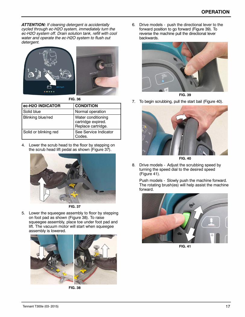
3. ec-H2O models - The ec-H2O system willautomatically turn on at start up. To turn off theec-H2O system, press the ec-H2O switch locatedbelow the key switch (Figure 36).
ATTENTION: During first time use and after replacingthe water conditioning cartridge, the ec-H2O systemwill automatically override the selected solution flowrate for up to 75 minutes.
OPERATION
Tennant T300e (03- 2015) 17
ATTENTION: If cleaning detergent is accidentallycycled through ec-H2O system, immediately turn theec-H2O system off. Drain solution tank, refill with coolwater and operate the ec-H2O system to flush outdetergent.
FIG. 36
ec-H2O INDICATOR CONDITIONSolid blue Normal operationBlinking blue/red Water conditioning
cartridge expired.Replace cartridge.
Solid or blinking red See Service IndicatorCodes.
4. Lower the scrub head to the floor by stepping onthe scrub head lift pedal as shown (Figure 37).
FIG. 37
5. Lower the squeegee assembly to floor by steppingon foot pad as shown (Figure 38). To raisesqueegee assembly, place toe under foot pad andlift. The vacuum motor will start when squeegeeassembly is lowered.
FIG. 38
6. Drive models - push the directional lever to theforward position to go forward (Figure 39). Toreverse the machine pull the directional leverbackwards.
FIG. 39
7. To begin scrubbing, pull the start bail (Figure 40).
FIG. 40
8. Drive models - Adjust the scrubbing speed byturning the speed dial to the desired speed(Figure 41).
Push models - Slowly push the machine forward.The rotating brush(es) will help assist the machineforward.
FIG. 41

OPERATION
18 Tennant T300e (03- 2015)
9. ec-H2O model: To adjust the solution flow ratewhen ec-H2O scrubbing, press the solution flowbutton located on the ec-H2O module (Figure 42).One LED= low, two LED’s=medium, and threeLED’s= high.
FIG. 42
10. To adjust the solution flow rate when conventionalscrubbing, turn the solution flow control knoblocated underneath machine (Figure 43).
NOTE: The solution flow control knob is only functionalwhen conventional scrubbing.
FIG. 43
11. T300e model option - When extra brush pressureis needed for heavily soiled areas lift the downpressure lever (Figure 44).
NOTE: Release the down pressure level when raisingscrub head.
FIG. 44
12. To stop scrubbing, release the start bail and raisethe scrub head and squeegee assembly off floor.Turn key off and set parking brake, if equipped.
WHILE OPERATING MACHINE
WARNING: Flammable materials materials orreactive metals can cause an explosion or fire. Donot pick up.
1. Overlap each scrub path by 2 inches (5 cm).
2. Keep machine moving to prevent damage to floorfinish.
3. Wipe squeegee blades with a cloth if blades leavestreaks.
4. Avoid bumping the machine into posts and walls.
FOR SAFETY: When operating machine, do notscrub on inclines that exceed 9% grade ortransport on inclines that exceed 21% grade.
5. Pour a recommended foam control solution into therecovery tank if excessive foam appears.
ATTENTION: Foam buildup will not activate thefloat shut-off screen, vacuum motor damage willresult.
6. Use the double scrubbing method for heavily soiledareas. First scrub the area with the squeegee up,let solution set for 3-5 minutes, then scrub the areaa second time with squeegee down.
7. Orbital Scrub Head Model - Use caution whenworking near the tile cove (Figure 45) and floormounted fixtures such as pedestal sinks and otherbreakable items. Keep the metal scrub head edgeaway to avoid possible damage.
Tile Cove
FIG. 45
8. When leaving the machine unattended, remove thekey and set the parking brake, if equipped.
9. Do not operate machine in areas where theambient temperature is above 110F/43C or belowfreezing 32F/0C.

OPERATION
Tennant T300e (03- 2015) 19
EMERGENCY SHUT-OFF BUTTON (Drive models)
Push the emergency shut-off button in the event of anemergency (Figure 46). This red button shuts off allpower to machine. To regain power, turn the buttonclockwise and restart the key.
Only use this button in the event of an emergency. It isnot intended for routine machine shutdown.
FIG. 46
BATTERY DISCHARGE INDICATOR
The battery discharge indicator (BDI) displays thecharge level of the batteries while the machine isoperating. When the batteries are fully charged, all fiveindicators are lit (Figure 47). When the discharge levelreaches the red light, stop scrubbing and recharge thebatteries. If the red light begins to flash, the scrubbingfunction will automatically shut off to protect thebatteries from total discharge. Drive Model: Themachine will still propel when the red light is flashing,this will allow user to transport machine to chargingstation.
FIG. 47
CIRCUIT BREAKER PANEL
The machine is equipped with resettable circuitbreakers to protect the machine from a currentoverload. If a circuit breaker trips, disconnect thebattery cable connection and reset the breaker bypressing the reset button after the breaker has cooleddown. Reconnect the battery cable connection. If thecircuit breaker does not reset or continues to tripcontact service personnel.
The circuit breaker panel is located near the batterycompartment and identified as described below(Figure 48).
FIG. 48
CircuitBreaker Rating Circuit protected
CB1 4 A Key switch, control boardCB2 4 A ec-H2O moduleCB3 4 A ec-H2O pumpCB4 30 A PropelCB5 37 A Brush motorCB6 20 A Vacuum motor
FOR SAFETY: When servicing machine, all repairsmust be performed by trained personnel.
HOUR METER
The hour meter records the number of hours themachine has been operated. Use the hour meter toperform specific maintenance procedures and to recordservice history (Figure 49).
FIG. 49

OPERATION
20 Tennant T300e (03- 2015)
DRAINING TANKS
FOR SAFETY: Before leaving or servicing machine,stop on level surface, turn off machine, remove keyand set parking brake if equipped.
DRAINING RECOVERY TANK
Drain and clean the recovery tank daily and betweensolution tank refills.
1. Transport the machine to drain area.
2. For models equipped with drain hose caps, holdthe hose upward, remove cap then slowly lowerhose to drain. For models equipped with flowcontrol valve drain hose, lower hose and slowlyopen valve to drain (Figure 50).
FIG. 50
NOTE: When using a bucket to drain the machine, donot use the same bucket to fill the solution tank.
3. Remove and clean the float shut-off screen (Figure51).
FIG. 51
4. Option - Remove the debris tray and empty(Figure 52).
FIG. 52
5. Rinse out the recovery tank with clean water andwipe clean of any soil residue (Figure 53).
FIG. 53
DRAINING SOLUTION TANK
Drain the solution tank daily.
1. Transport the machine to drain area.
FOR SAFETY: Before leaving or servicing machine,stop on level surface, turn off machine, remove keyand set parking brake if equipped.
2. To drain remaining water from solution tank, pullthe solution hose from the accessory rail (Figure54).
FIG. 54
Firmly reconnect the solution hose to accessory railafter draining tank.

OPERATION
Tennant T300e (03- 2015) 21
3. Rinse out solution tank with clean water (Figure55).
FIG. 55
4. Remove the solution tank filter and clean screenafter every 50 hours of use (Figure 56). Solutionfilter is located under machine at rear. Drainsolution tank before removing filter.
FIG. 56
SERVICE INDICATOR CODES
When the machine or battery charger detects a fault, the service indicator will flash. A fault code will be provided todetermine problem as described below.
Flashing serviceindicator
Flashing LEDfault code
T300e Control Panel
LED Fault Code= Flashing CAUSE SOLUTION
Emergency stop button activated. Release emergency stop button and restartmachine.
S S S Brush motor wiring, connector or control boardproblem.
Contact service.
S S S S Vacuum motor wiring, connector or controlboard problem.
Contact service.
S S S Severe environment detergent pump wiring,connector or control board problem.
Contact service.
S S S Propel circuit breaker tripped. Disconnect battery and reset circuit breaker. Iftrip repeats, contact service.
S S Software load failure. Contact service.
S S S Propel I-Drive faultPropel I-Drive communication lost
Restart machine. If fault repeats, contactservice.
S S S Propel motor shorted fault Contact service.
S S Brush motor over current Contact service.

OPERATION
22 Tennant T300e (03- 2015)
SERVICE INDICATOR CODES - Continued
LED Fault Code= Flashing CAUSE SOLUTION
S S Start bail is pulled or obstructed before turningmachine on.
Release start bail or remove bail obstructionbefore turning machine on.
S S Brush motor control board faultVacuum motor control board fault
Disconnect battery cable connection and con-tact service to replace control board.
S Vacuum motor over current. Contact service.
S S S Vacuum motor shorted fault. Contact service.
S S Brush motor shorted fault. Contact service.
S SCharger communication faultScrub control board comm. faultec-H2O system comm. fault
Restart. If fault code persists, contact service.
ON-BOARD BATTERY CHARGER SERVICE INDICATOR CODES
LED Fault Code= Flashing CAUSE SOLUTION
S S Charger error condition. Contact service.
S S S Charger is not connected to battery pack. Check cable connections.
S S S SCharger overheated. Let charger cool. Move to well ventilated area.
Charge batteries in areas with temperatures80F/27C or less. If fault persists, contact ser-vice.
S S Charger communication fault Restart charger. If fault code persists, contactservice.
S S Charger timer exceeded maximum chargingtime. Interrupts charging cycle.
Replace Batteries.

OPERATION
Tennant T300e (03- 2015) 23
ec-H2O SYSTEM SERVICE INDICATOR CODES - OPTION
Flashingserviceindicator
FlashingLED faultcode
T300e Control Panel
Solid orblinking Redec-H2Oindicator
LED Fault Code= Flashing CAUSE SOLUTION
S S S ec-H2O pump wiring, connector or controlboard problem.
Contact service.
S ec-H2O pump over current Contact service.
S S S S ec-H2O pump shorted fault Contact service.
S S S ec-H2O system breaker trippedec-H2O pump breaker tripped
Reset circuit breaker. If trip repeats, contactservice.
ecH2O indicatorsolid red
ec-H2O pump shorted faultec-H2O control board faultWater conditioning pump openWater conditioning pump fault
Contact service.
ecH2O indicatorblinking red*
ec-H2O pressure switch tripec-H2O system over regulationNo ec-H2O cell currentec-H2O cell over currentec-H2O cell shorted fault
Contact service.
ecH2O indicatorblinking blue/red
Water conditioning cartridge expired Replace water conditioning cartridge.
*Verify if cleaning detergent was added to solution tank. If ec-H2O system was operated with cleaning detergent, drain solutiontank, add clear water and operate the ec-H2O system until the fault code clears.

MAINTENANCE
24 Tennant T300e (03- 2015)
MAINTENANCE CHART
6
14
4
1
3
2
7
18
14
13
9
14
12
10
15
15
12
1
9
11
IntervalPersonResp. Key Description Procedure
Daily O 1 Pad(s) Check, flip or replaceO 1 Brush(es) Check, cleanO 2 Cylindrical Brushes Check, cleanO 3 Recovery tank Drain, rinse, clean float shut-off screen
and debris tray if equipped
O 4 Solution tank Drain, rinseO 6 Squeegee Clean, check for damage and wearO 7 Batteries Charge if necessaryO 8 Debris trough Clean
O 9 Scrub head skirt Check for damage and wearWeekly O 7 Battery cells Check electrolyte level
O 6 Squeegee assembly drip trap reservoir Check, clean
50 Hours O 2 Cylindrical brushes. Rotate brushes. Check for wear
O 2 Cylindrical scrub head Clean underside of scrub headO 3 Recovery tank lid seal Check for wear.
O 10 Solution tank filter Clean100 Hours O 7 Battery watering system (option) Check hoses for damage and wear200 Hours O 7 Batteries, terminals and cables Check and clean500 Hours T 11 Lower orbital isolators Replace (4 qty)750 Hours T 12 Vacuum motor Replace carbon brushes1250 Hours T 13 Propel motor Replace carbon brushes
T 14 Brush motor Replace carbon brushesT 15 Brush belt Replace belt
O = Operator T = Trained Personnel

MAINTENANCE
Tennant T300e (03- 2015) 25
MACHINE MAINTENANCE
To keep the machine in good working condition, simplyperform the following maintenance procedures.
FOR SAFETY: Before leaving or servicing machine,stop on level surface, turn off machine, remove keyand set parking brake if equipped.
FOR SAFETY: When servicing machine wearpersonal protection equipment as needed. Allrepairs must be performed by trained personnel
AFTER DAILY USE
1. Drain and rinse out the recovery tank (Figure 57).See DRAINING TANKS.
FIG. 57
2. Option - Remove the debris tray and empty(Figure 58).
FIG. 58
3. Remove and clean the float shut-off screen(Figure 59).
FIG. 59
4. Drain and rinse out the solution tank (Figure 60).
FIG. 60
5. Disk scrub head - Turn pad over or replace whenworn (Figure 61).
FIG. 61
Orbital scrub head - Turn the work pad over orreplace when worn (Figure 62).
FIG. 62
6. Insta-Click pad driver/brushes - clean any debrisbuildup from hub connection area (Figure 63).
FIG. 63

MAINTENANCE
26 Tennant T300e (03- 2015)
7. Wipe the squeegee blades clean. Inspect bladesfor wear and damage (Figure 64). Rotate blade ifworn. See SQUEEGEE BLADE REPLACEMENT.
FIG. 64
8. Check the scrub head skirt for wear or damage(Figure 65). Replace if worn or damaged.
FIG. 65
9. Clean the outside surface of the machine with anall purpose cleaner and damp cloth (Figure 66).
FIG. 66
10. Cylindrical scrub head - Remove and clean debristrough (Figure 67).
FIG. 67
11. Charge batteries (Figure 68). See BATTERIES.
FIG. 68
AFTER WEEKLY USE
1. Check the electrolyte level in all batteries (Figure69). See BATTERIES.
FIG. 69
2. Remove the drip trap cover from the squeegeeassembly and clean reservoir (Figure 70).
FIG. 70

MAINTENANCE
Tennant T300e (03- 2015) 27
AFTER EVERY 50 HOURS OF USE
1. Remove the solution tank filter and clean screen(Figure 71). Turn the filter bowl counter-clockwiseto remove. Make sure to drain solution tank beforeremoving filter.
FIG. 71
2. Cylindrical brushes - Rotate brushes from front torear (Figure 72). Replace brushes when they nolonger clean effectively.
FIG. 72
3. Cylindrical scrub head - Remove debris buildupfrom underside of scrub head (Figure 73).
FIG. 73
4. Inspect and clean the seal on the recovery tank lid(Figure 74). Replace seal if damaged.
FIG. 74
AFTER EVERY 100 HOURS OF USE
If machine is equipped with the optional batterywatering system, check the watering hoses andconnections for damage and wear (Figure 75). Replacesystem if damaged.
FOR SAFETY: When servicing batteries, wearpersonal protection equipment as needed. Avoidcontact with battery acid.
FIG. 75
ELECTRIC MOTORS
Replace motor carbon brushes as indicated. Contacttrained personnel for carbon brush replacement.
Carbon Brush Replacement Hours
Vacuum motor 750
Propel motor (drive model) 1250
Disk brush motor 1250
Cylindrical brush motor 1250
Orbital brush motor 1250

MAINTENANCE
28 Tennant T300e (03- 2015)
BELTS
FOR SAFETY: Before leaving or servicing machine,stop on level surface, turn off machine, remove keyand set parking brake if equipped.
Replace belts every 1250 hours. Contact trainedpersonnel for belt replacement (Figure 76).
Cylindrical Brush Drive Belt
Dual Disk Brush Drive Belt
FIG. 76
ORBITAL SCRUB HEAD ISOLATORS
FOR SAFETY: Before leaving or servicing machine,stop on level surface, turn off machine, remove keyand set parking brake if equipped.
Replace the four lower vibration isolators every 500hours. The lower isolators (hidden) are locatedbetween the deck plate the driver plate. Contact trainedpersonnel for isolator replacement (Figure 77).
FIG. 77
BATTERIES
FOR SAFETY: Before servicing machine, stop onlevel surface, turn off machine, remove key and setparking brake if equipped.
The lifetime of the batteries depends on their propermaintenance. To get the most life from the batteries;
S Do not charge the batteries more than once a dayand only after running the machine for a minimum of15 minutes.
S Do not leave the batteries partially discharged forlong period of time.
S Only charge the batteries in a well-ventilated area toprevent gas build up. Charge batteries in areas withambient temperatures 80_F / 27_C or less.
S Allow the charger to complete charging the batteriesbefore re-using the machine.
S Maintain the proper electrolyte levels of flooded (wet)batteries by checking levels weekly.
Your machine is equipped with either flooded (wet)lead-acid or maintenance-free batteries supplied byTennant.
FOR SAFETY: When servicing machine, keep allmetal objects off batteries. Avoid contact withbattery acid.
MAINTENANCE-FREE BATTERIES
Maintenance-free (Sealed AGM) batteries do notrequire watering. Cleaning and other routinemaintenance is still required.
FLOODED (WET) LEAD-ACID BATTERIESThe flooded (wet) lead-acid batteries require routinewatering as described below. Check the batteryelectrolyte level weekly.
NOTE: Do Not check the electrolyte level if themachine is equipped with the optional battery wateringsystem. Proceed to the BATTERY WATERINGSYSTEM.
The electrolyte level should be slightly above thebattery plates as shown before charging (Figure 78).Add distilled water if low. DO NOT OVERFILL. Theelectrolyte will expand and may overflow whencharging. After charging, distilled water can be addedup to about 3 mm (0.12 in) below the sight tubes.

MAINTENANCE
Tennant T300e (03- 2015) 29
Before Charging After Charging
FIG. 78
NOTE: Make sure the battery caps are in place whilecharging. There may be a sulfur smell after chargingbatteries. This is normal.
CHECKING CONNECTIONS / CLEANING
After every 200 hours of use, check for loose batteryconnections and clean the surface of the batteries,including terminals and cable clamps to prevent batterycorrosion. Use a scrub brush with a strong mixture ofbaking soda and water (Figure 79). Do not removebattery caps when cleaning batteries.
FIG. 79
CHARGING BATTERIES
The charging instructions in this manual are intendedfor the battery charger supplied with your machine. Theuse of other battery chargers that are not supplied andapproved by Tennant are prohibited.
If your machine is equipped with an off-board batterycharger refer to the charger’s owners manual foroperating instructions. Contact distributor or Tennantfor battery charger recommendations if machine is notequipped with charger.
FOR SAFETY: The use of incompatible batterychargers may damage battery packs andpotentially cause a fire hazard.
IMPORTANT NOTICE: The battery charger is set tocharge the battery type supplied with your machine. Ifyou choose to change to a different battery type orcapacity (i.e. flooded (wet) lead-acid,maintenance-free, sealed, AGM batteries, etc.), thecharger’s charging profile must be changed to preventbattery damage. See BATTERY CHARGERSETTINGS.
1. Transport the machine to a well-ventilated area.
WARNING: Batteries emit hydrogen gas.Explosion or fire can result. Keep sparks and openflame away when charging.
2. Park the machine on a flat, dry surface, turn offmachine and remove key.
FOR SAFETY: When servicing batteries, stop onlevel surface, turn off machine, remove key and setparking brake if equipped.
3. If the machine is equipped with flooded (wet) lead-acid batteries check the battery electrolyte levelweekly before charging. See FLOODED (WET)LEAD-ACID BATTERIES.
4. For models equipped with on-board chargers,remove the charger’s power cord from the storagehooks and plug power cord into a properlygrounded wall outlet (Figure 80).
FIG. 80

MAINTENANCE
30 Tennant T300e (03- 2015)
For models equipped with off-board chargers, firstconnect the charger’s DC cord into the machine’sbattery charge receptacle then plug the AC powersupply cord into a properly grounded wall outlet(Figure 81). Refer to the off-board battery charger’sowner manual for operating instructions.
FOR SAFETY: Do not disconnect the off-boardcharger’s DC cord from the machine’s receptaclewhen the charger is operating. Arcing may result. Ifthe charger must be interrupted during charging,disconnect the AC power supply cord first.
FIG. 81
5. The charger will automatically begin charging andand shut off when fully charged. The maximumcharging cycle may take up to 6- 12 hoursdepending on battery type.On-board battery charger: The battery dischargeindicator lights will ripple back and forth during thecharging cycle. When all five lights are flashing, thecharging cycle is complete (Figure 82).
FIG. 82
6. After charging batteries unplug the power supply cordand wrap cord around the cord hooks (Figure 83).For models equipped with an off-board charger,always disconnect the AC power supply cord firstbefore disconnecting charger from machine.
FIG. 83
BATTERY CHARGER SETTINGS
The battery charger is set to charge the battery typesupplied with your machine. If you choose to change toa different battery type or capacity, the charger’scharging profile must be changed to prevent batterydamage.
For machine’s equipped with an off-board batterycharger, refer to the off-board charger’s owner manualto change the charger’s charging profile.
FOR SAFETY: When servicing batteries, stop onlevel surface, turn off machine, remove key and setparking brake if equipped.
To change the on-board battery charger settings for adifferent battery type :
1. Disconnect the battery cable connection atmachine (Figure 84).
FIG. 84
2. Unwrap the battery charger power cord from thecord hooks.
3. Using a T25 star screwdriver, remove the twoscrews located at the bottom of the control consoleto access battery charger (Figure 85).
FIG. 85

MAINTENANCE
Tennant T300e (03- 2015) 31
4. Disconnect the battery cable, power cord and wireharness from charger. Using a T25 starscrewdriver, remove the four screws that mountcharger to machine (Figure 86). Remove chargerfrom machine.
FIG. 86
5. Remove the black cap from bottom side of chargerto access the profile dial (Figure 87)
FIG. 87
6. Using a small standard screwdriver, turn the dial tothe appropriate battery type according to thefollowing chart (Figure 88).
FIG. 88
DialPosition
Battery Description Settingswith AH Ranges
0 Factory setting*1 Wet, Trojan 105- 155 AH2 Wet, Enersys/Tab 105- 155 AH3 AGM, Discover 80- 150 AH4 AGM, Fullriver 80- 150 AH5 AGM, TPPL, Enersys 20- 40 AH6 Gel, Sonnenschein 80- 150 AH
* The factory setting, dial position “0”, is pre-programmedto accommodate the battery type supplied with newmachine. After the dial is changed from the factorysetting, it should not be returned to “0” otherwise batterydamage may result.
7. Replace the black cap on charger, reinstall batterycharger and replace control console.
8. Reconnect the battery cable connection.

MAINTENANCE
32 Tennant T300e (03- 2015)
HYDROLINK BATTERY WATERING SYSTEM(Trojan 155AH Battery Option)
The following instructions are for models equipped withthe HydroLINK battery watering system option.
The optional HydroLINK battery watering systemprovides a safe and easy way to maintain the properelectrolyte levels in your batteries. It is designedexclusively for Trojan flooded (wet) lead-acidbatteries.
FOR SAFETY: When servicing machine, wearpersonal protection equipment as needed. Avoidcontact with battery acid.
Before using the battery watering system check hosesand connections for damage or wear.
1. Fully charge batteries prior to using the batterywatering system. Do not add water to batteriesbefore charging, the electrolyte level will expandand may overflow when charging.
2. After charging batteries, check the batteryelectrolyte level indicators located on the batterycovers (Figure 89). If the level indicator is whiteadd water as described in the followinginstructions. If the level indicators are black theelectrolyte is at the correct level, no water isrequired.
FIG. 89
3. Locate the battery fill hose coupler inside thebattery compartment. Remove the dust cap andconnect the hand pump hose (Figure 90).
FIG. 90
4. Submerge the other end of the hand pump hoseinto a bottle of distilled water (Figure 91).
DistilledWater
FIG. 91
5. Squeeze the bulb on the hand pump hose until firm(Figure 92). The level indicators will turn blackwhen full.
FIG. 92
6. After adding water, replace the dust cap on thebattery fill hose and store the hand pump hoseinside the machine’s battery compartment for futureuse.

MAINTENANCE
Tennant T300e (03- 2015) 33
SQUEEGEE BLADE REPLACEMENT
FOR SAFETY: Before leaving or servicing machine,stop on level surface, turn off machine, remove keyand set parking brake if equipped.Each squeegee blade has four wiping edges. When theblades become worn, simply rotate the bladesend-for-end or top-to-bottom for a new wiping edge.Replace blade if all four edges are worn.
1. Remove the squeegee assembly from the machine.
2. Fully loosen the two outside knobs on squeegeeassembly. This will separate the spring loadedblade retainer from squeegee frame (Figure 93). Toloosen the knobs quickly, squeeze the bladeretainer and squeegee frame together.
FIG. 93
3. Remove worn blade(s) from the blade retainer(Figure 94).
FIG. 94
4. Rotate the rear blade to a new wiping edge (Figure95). Make sure to align the slots in the blade withretainer tabs.
FIG. 95
5. Squeeze the squeegee frame and blade retainertogether and re-tighten the two outside knobs(Figure 96).
FIG. 96

MAINTENANCE
34 Tennant T300e (03- 2015)
ec-H2O NanoClean WATER CONDITIONINGCARTRIDGE REPLACEMENT
FOR SAFETY: Before leaving or servicing machine,stop on level surface, turn off machine, remove keyand set parking brake if equipped.The water conditioning cartridge is required to bereplaced when it reaches its maximum water usage orexpiration time of when the cartridge was activated,which ever comes first. The control panel will signal acode when it’s time to replace cartridge. SeeCONTROL PANEL OPERATION for further details.
Depending on machine usage, on average, a newcartridge can last anywhere from 12 months for heavymachine usage to 24 months for light machine usage.
ATTENTION: During first time use and after replacingthe water conditioning cartridge, the ec-H2O systemwill automatically override the selected solution flowrate for up to 75 minutes.
1. Park the machine on a level surface, remove thekey and set parking brake, if equipped.
2. Lift the recovery tank to access the ec-H2O waterconditioning cartridge (Figure 97). Drain recoverytank before lifting tank.
FIG. 97
3. Disconnect the two hose connectors from the topof the cartridge by pressing the gray collars inwardand pulling the connectors outward (Figure 98). Liftcartridge to remove.
GrayCollar
FIG. 98
4. Fill in the installation date on the new cartridgelabel (Figure 99).
FIG. 99
5. Install the new cartridge and reconnect the twohoses. Make sure the hose connectors are fullyinserted into the cartridge.
6. Reset timer for new cartridge.
Carefully read and understand all steps first beforeperforming procedure.a. Turn key on.b. Press and hold the service switch, located on
the ec-H2O module, for 10 seconds. Afterreleasing service switch, the three solution flowindicator lights will begin to (ripple) move backand forth (Figure 100).
c. Within 5 seconds after releasing the serviceswitch, while the three indicator lights aremoving back and forth, quickly press andrelease the solution flow button located onec-H2O module (Figure 100).The three indicator lights will then blink threetimes to indicate timer has been reset.Repeat process if the three indicator lights donot blink three times.
Service switch 3 indicator lights
Solution flow button
FIG. 100

MAINTENANCE
Tennant T300e (03- 2015) 35
LOADING/UNLOADING MACHINE FORTRANSPORTING
When transporting the machine by use of trailer ortruck, carefully follow the loading and tie-downprocedure:
1. Raise the scrub head and remove squeegeeassembly.
2. Use a ramp that can support the machine weightand operator and carefully load machine. Do notoperate the machine on a ramp incline thatexceeds a 21% grade level (Figure 101). A winchmust be used when ramp incline exceeds a 21%grade level.
FOR SAFETY: When loading/unloading machineonto/off truck or trailer, use a ramp that cansupport the machine weight and operator.
FOR SAFETY: Do not operate the machine on aramp incline that exceeds a 21% grade level.
FIG. 101
3. Once loaded, position the front of the machine upagainst the front of the trailer or truck. Lower thescrub head, turn key off and set parking brake, ifequipped (Figure 102).
4. Place a block behind each wheel (Figure 102).
5. Using tie-down straps, secure the machine usingthe four tie-down brackets located on the machineframe (Figure 102). It may be necessary to installtie-down brackets to the floor of your trailer ortruck.
ATTENTION: Do not use control console areaor accessory storage rails for tie-downlocations, damage may occur.
FIG. 102
STORING MACHINE
The following steps should be taken when storing themachine for extended periods of time.
1. Charge the batteries before storing machine toprolong the life of the batteries. Recharge batteriesevery 3 months.
2. Drain and rinse recovery tank and solution tank.
3. Store the machine in a dry area with squeegee andscrub head in the up position.
ATTENTION: Do not expose machine to rain, storeindoors.
4. Open the recovery tank lid to promote aircirculation.
NOTE: To prevent potential machine damage storemachine in a rodent and insect free environment.
FREEZE PROTECTION
Storing machine in freezing temperatures.
1. Completely drain solution tank and recovery tank.
2. Empty the water from the solution tank filter locatedunder machine. Replace filter.
3. Pour 1 gallon / 4 liters of propylene glycol basedrecreational vehicle (RV) antifreeze into thesolution tank.
4. Turn machine on and operate the solution flowsystem. Turn the machine off when the antifreezeis visible on floor.
Models equipped with ec-H2O option - Operateec-H2O scrubbing to cycle antifreeze throughsystem.
5. After storing machine in freezing temperatures,drain any remaining antifreeze from the solutiontank. Add clean water to solution tank and tooptional detergent tank and operate the machine toflush system.

MAINTENANCE
36 Tennant T300e (03- 2015)
TROUBLESHOOTINGPROBLEM CAUSE SOLUTION
Service indicator icon isblinking
Machine or on-board battery chargerfault has been detected
See SERVICE INDICATOR CODES
ec-H2o indicator icon isred or blinking red
ec-H2O system fault has beendetected
See SERVICE INDICATOR CODES
Machine will not operate Emergency stop button activated Turn button to reset
Machine fault detected See SERVICE INDICATOR CODES
Batteries discharged Recharge batteries
Loose battery cable(s) Tighten loose cables
Faulty battery(s) Replace battery(s)
Faulty key switch Contact service
Faulty start bail switch Contact service
Circuit breaker tripped Reset circuit breaker
Faulty control board Contact service
On-board battery chargerwill not operate
Plug not connected to power supply Check plug connection
Batteries over discharged Replace batteries
Battery charger fault detected See SERVICE INDICATOR CODES
Faulty charger Replace charger
Machine will not propel(Drive Model)
Propel fault has been detected. See SERVICE INDICATOR CODES
Circuit breaker tripped Reset circuit breaker
Faulty propel motor or wiring Contact service
Worn carbon brushes in motor Contact service
Brush motor will notoperate
Brush motor fault has been detected. See SERVICE INDICATOR CODES
Faulty pad motor or wiring Contact service
Circuit breaker tripped Reset circuit breaker
Worn carbon brushes in motor Contact service
Broken or loose belt (dualdisk/cylindrical models)
Contact service
Vacuum motor will notoperate
Squeegee assembly is raised off floor Lower squeegee assembly to floor
Vacuum motor fault has been detected See SERVICE INDICATOR CODES
Faulty vacuum motor or wiring Contact service
Circuit breaker tripped Reset circuit breaker
Poor scrubbingperformance
Debris caught in brush/pad Remove debris
Worn brush/pad Replace brushes/pad
Incorrect brush pressure Adjust brush pressure
Wrong brush/pad type Use correct brush/pad for application
Low battery charge Recharge batteries
MAINTENANCE
Tennant T300e (03- 2015) 37
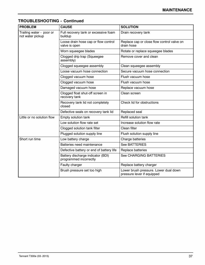
TROUBLESHOOTING - ContinuedPROBLEM CAUSE SOLUTION
Trailing water - poor ornot water pickup
Full recovery tank or excessive foambuildup
Drain recovery tank
Loose drain hose cap or flow controlvalve is open
Replace cap or close flow control valve ondrain hose
Worn squeegee blades Rotate or replace squeegee blades
Clogged drip trap (Squeegeeassembly)
Remove cover and clean
Clogged squeegee assembly Clean squeegee assembly
Loose vacuum hose connection Secure vacuum hose connection
Clogged vacuum hose Flush vacuum hose
Clogged vacuum hose Flush vacuum hose
Damaged vacuum hose Replace vacuum hose
Clogged float shut-off screen inrecovery tank
Clean screen
Recovery tank lid not completelyclosed
Check lid for obstructions
Defective seals on recovery tank lid Replaced seal
Little or no solution flow Empty solution tank Refill solution tank
Low solution flow rate set Increase solution flow rate
Clogged solution tank filter Clean filter
Plugged solution supply line Flush solution supply line
Short run time Low battery charge Charge batteries
Batteries need maintenance See BATTERIES
Defective battery or end of battery life Replace batteries
Battery discharge indicator (BDI)programmed incorrectly
See CHARGING BATTERIES
Faulty charger Replace battery charger
Brush pressure set too high Lower brush pressure. Lower dual downpressure lever if equipped

SPECIFICATIONS
38 Tennant T300e (03- 2015)
GENERAL MACHINE DIMENSIONS/CAPACITIES/PERFORMANCE
MODEL 17 in / 43 cm Disk(Push)
20 in / 50 cm Disk(Push)
17 in / 43 cm Disk(Drive)
20 in / 50 cm Disk(Drive)
Length 51.25 in / 1302 mm 54 in / 1372 mm 51.25 in / 1302 mm 54 in / 1372 mm
Width 20 in / 508 mm 22 in / 559 mm 20 in / 508 mm 22 in / 559 mm
Height 43.1 in / 1095 mm 43.1 in / 1095 mm 43.1 in / 1095 mm 43.1 in / 1095 mm
Weight 220 Ib / 98 kg 230 Ib / 104 kg 230 Ib / 104 kg 240 Ib / 109 kg
Weight (with batteries) 366 Ib / 166 kg 376 Ib / 171 kg 390 Ib / 177 kg 400 Ib / 181 kg
GVW 457 Ib / 207 kg 467 Ib / 212 kg 482 Ib / 219 kg 492 Ib / 223 kg
Squeegee width 30.4 in / 772 mm
Recovery tank capacity 14 gal / 53 L
Solution tank capacity 11 gal / 42 L
Scrubbing path width 16.9 in / 430 mm 19.9 in / 505 mm 16.9 in / 430 mm 19.9 in / 505 mm
Down pressure 47 lbs / 21.3 kg 52 lbs / 23.5 kg 47 lbs / 21.3 kg 51 lbs / 23 kg
Dual down pressure 88 lbs / 40 kg 92 lbs / 41.7 kg 86 lbs / 39 kg 90 lbs / 41 kg
Scrubbing speed Pad assist 200 fpm / 61 mpm
Transport speed n/a n/a 240 fpm / 73 mpm
Reverse speed n/a n/a 144 fpm / 44 mpm
Productivity rate - estimated actual 9,340ft2/hr / 868m2/hr 11,208ft2/hr / 1041m2/hr 12,453ft2/hr / 1157m2/hr 14,943ft2/hr / 1388m2/hr
ec-H2O productivity rate - est. actual 9,668 ft2/hr / 898 m2/hr 11,602ft2/hr / 1078m2/hr 12,891ft2/hr / 1198m2/hr 15,469ft2/hr / 1437m2/hr
Aisle turnaround width 52 in / 1321 mm 54.5 in / 1384 mm 52 in / 1321 mm 54.5 in / 1384 mm
Ramp incline for scrubbing 9% maximum
Ramp incline for transporting 21% maximum
Ramp incline for loading- empty tanks 21% maximum
Solution flow rate - T300e .5 gpm / 1.9 L/min maximum
ec-H2O solution flow rate Low: .12 gpm / .45 L/min, Med: .25 gpm / .94 L/min, High: .35 gpm / 1.3 L/min
Brush motor 24 VDC, 1hp / .75kW
Propel motor n/a n/a 24 VDC, .23 hp / .175 kW
Vacuum motor 24 VDC, .5hp / .37kW
Water lift 34.5 in / 876 mm
ec-H2O solution pump 24 VDC, 1.0 gpm / 3.8 L/min, min open flow
Machine voltage 24 VDC
Battery capacity 2- 12V 105AH C/20 Wet, 2- 12V 130AH C/20 Wet,2- 12V 155AH C/20 Wet, 2- 12V 140AH C/20 Sealed/AGM
Total power consumption 31.5A nominal 36.5A nominal 34.5A nominal 39.5A nominal
Battery Charger - on-board 100- 240VAC, 50/60Hz, 24VDC, 13A
Battery Charger - smart off-board 100- 240VAC, 50/60Hz, 24VDC, 13A
Protection grade IPX3
Sound pressure level LpA* 67 dB(A) 67 dB(A) 67 dB(A) 67 dB(A)
Sound uncertainty KpA* 0.8 dB(A) 0.8 dB(A) 0.8 dB(A) 0.8 dB(A)
Sound power level uncertainty LpA -uncertainty KpA*
84.3 dB(A) 84.3 dB(A) 84.3 dB(A) 84.3 dB(A)
Machine vibration at hand-arm* <2.5 m/s2
Ambient operating temperature Min: 32F/0C, Max: 110F/43C
*Values per EN 60335- 2- 72. Specifications are subject to change without notice.

SPECIFICATIONS
Tennant T300e (03- 2015) 39
GENERAL MACHINE DIMENSIONS/CAPACITIES/PERFORMANCE
MODEL 24 in / 60 cmDual Disk
20 in / 50 cmCylindrical Brush
20 in / 50 cmOrbital
Length 51.75 in / 1314 mm 50.5 in / 1283 mm 49 in / 1245 mm
Width 26 in / 660 mm 25 in / 635 mm 20.5 in / 521 mm
Height 43.1 in / 1095 mm 43.1 in / 1095 mm 43.1 in / 1095 mm
Weight 250 Ib / 113 kg 250 Ib / 113 kg 255 Ib / 216 kg
Weight (with batteries) 410 Ib / 186 kg 410 Ib / 186 kg 415 Ib / 188 kg
GVW 502 Ib / 228 kg 502 Ib / 228 kg 507 Ib / 230 kg
Squeegee width 30.4 in / 772 mm
Recovery tank capacity 14 gal / 53 L
Solution tank capacity 11 gal / 42 L
Scrubbing path width 23.6 in / 600 mm 19.7 in / 500 mm 19.7 in / 500 mm
Down pressure 57 lbs / 26 kg 53 lbs / 24 kg 63 lbs / 28.5 kg
Dual down pressure 97 lbs / 44 kg 64 lbs / 29 kg 109 lbs / 49.5 kg
Scrubbing speed 200 fpm / 61 mpm
Transport speed 240 fpm / 73 mpm
Reverse speed 144 fpm / 44 mpm
Productivity rate - estimated actual 18,264ft2/hr / 1697m2/hr 14,943ft2/hr / 1388m2/hr 14,943ft2/hr / 1388m2/hr
ec-H2O productivity rate - est. actual 18,906ft2/hr / 1756m2/hr 15,469ft2/hr / 1437m2/hr 15,469ft2/hr / 1437m2/hr
Aisle turnaround width 53.5 in / 1346 mm 52 in / 1321 mm 49 in / 1245 mm
Ramp incline for scrubbing 9% max.
Ramp incline for transporting 21% max.
Ramp incline for loading- empty tanks 21% max.
Solution flow rate .5 gpm / 1.9 L/min maximum
ec- H2O solution flow rate Low: .12 gpm / .45 L/min, Med: .25 gpm / .94 L/min, High: .35 gpm / 1.3 L/min
Brush motor 24 VDC, 1hp / .75kW
Propel motor 24 VDC, .23 hp / .175kW
Vacuum motor 24 VDC, .5 hp / .37 kW
Water lift 34.5 in / 876 mm
ec- H2O solution pump 24 VDC, 1.0 gpm / 3.8 L/min, min open flow
Machine voltage 24 VDC
Battery capacity 2- 12V 105AH C/20 Wet, 2- 12V 130AH C/20 Wet,2- 12V 155AH C/20 Wet, 2- 12V 140AH C/20 Sealed/AGM
Total power consumption 36A nominal 40A nominal 30A nominal
Battery Charger - on-board 100- 240VAC, 50/60Hz, 24VDC, 13A
Battery Charger - smart off-board 100- 240VAC, 50/60Hz, 24VDC, 13A
Protection grade IPX3
Sound pressure level LpA* 67.7 dB(A) 68.7 dB(A) 67.5 dB(A)
Sound uncertainty KpA* 0.8 dB(A) 0.8 dB(A) 0.8 dB(A)
Sound power level uncertainty LpA -uncertainty KpA*
83.8 dB(A) 84.2 dB(A) 83.5 dB(A)
Machine vibration at hand-arm* <2.5 m/s2
Ambient operating temperature Min: 32F/0C, Max: 110F/43C
*Values per EN 60335- 2- 72. Specifications are subject to change without notice.

SPECIFICATIONS
40 Tennant T300e (03- 2015)
MACHINE DIMENSIONS
43.1 in1095 mm
30.4 in772 mm
SINGLE DISK MODEL
51.25 in1302 mm
17 in / 43 cmModel54 in
1372 mm
20 in / 50 cmModel
20 in508 mm
17 in / 43 cmModel22 in559 mm
20 in / 50 cmModel

SPECIFICATIONS
Tennant T300e (03- 2015) 41
43.1 in1095 mm
30.4 in772 mm
DUAL DISK MODEL
51.25 in1314 mm
26 in660 mm

SPECIFICATIONS
42 Tennant T300e (03- 2015)
43.1 in1095 mm
30.4 in772 mm
CYLINDRICAL BRUSH MODEL
50.5 in1283 mm
25 in635 mm

SPECIFICATIONS
Tennant T300e (03- 2015) 43
43.1 in1095 mm
30.4 in772 mm
ORBITAL PAD MODEL
49 in1245 mm
20.5 in521 mm