t m rl ts m l e t a e - setecom | servicios técnicos y...
TRANSCRIPT
ACCESSING THE MAIN FRONT PANEL CONFIGURATION EDITOR
• Ensure the generator(s) is at rest and the module is in STOP mode by pressing the Stop/Reset button.
• Press and hold the Stop button and Tick button together. • If a module security PIN has been set, the PIN number request is then shown.
• Press , the first ‘#’ changes to ‘0’. Press (up) or (down) button to adjust it to the correct value.
• Press (right) button when the first digit is correctly entered. The digit you have just entered will now show ‘#’ for security.
• The other digits of the PIN number. You can press (left) button if you need to move back to adjust one of the previous digits.
• When is pressed after editing the final PIN digit, the PIN is checked for validity. If the number is not correct, you must re-enter the PIN.
• If the PIN has been successfully entered (or the module PIN has not been enabled), the editor is displayed.
EDITING A PARAMETER • Enter the editor as described above.
• Press the (up), (down), (left) and (right) to cycle to the section you wish to view/change.
• Then press (up) or (down) to cycle to the parameter within the section you have chosen.
• To edit the parameter, press to enter edit mode. The parameter is highlighted blue to indicate that you are editing the value.
• Press the up or down buttons to change the parameter to the required value.
• Press to save the value. The parameter ceases flashing to indicate that it has been saved.
• To exit the editor at any time, press and hold the or button.
NNNNOOOOTTTTEEEE:::: TTTThhhheeee PPPPIIIINNNN nnnnuuuummmmbbbbeeeerrrr iiiissss nnnnooootttt sssseeeetttt bbbbyyyy DDDDSSSSEEEE wwwwhhhheeeennnn tttthhhheeee mmmmoooodddduuuulllleeee lllleeeeaaaavvvveeeessss tttthhhheeee ffffaaaaccccttttoooorrrryyyy.... IIIIffff tttthhhheeee mmmmoooodddduuuulllleeee has a PIN has a PIN has a PIN has a PIN ccccooooddddeeee sssseeeetttt,,,, tttthhhhiiiissss hhhhaaaassss bbbbeeeeeeeennnn iiiimmmmpppplllleeeemmmmeeeennnntttteeeedddd bbbbyyyy yyyyoooouuuurrrr ggggeeeennnneeeerrrraaaattttoooorrrr ssssuuuupppppppplllliiiieeeerrrr wwwwhhhhoooo sssshhhhoooouuuulllldddd bbbbeeee ccccoooonnnnttttaaaacccctttteeeedddd iiiiffff yyyyoooouuuu rrrreeeeqqqquuuuiiiirrrreeee tttthhhheeee ccccooooddddeeee.... IIIIffff tttthhhheeee ccccooooddddeeee hhhhaaaassss bbbbeeeeeeeennnn ‘‘‘‘lllloooosssstttt’’’’ oooorrrr ‘‘‘‘ffffoooorrrrggggooootttttttteeeennnn’’’’,,,, tttthhhheeee mmmmoooodddduuuulllleeee mmmmuuuusssstttt bbbbeeee returned to the DSE factory to have the module’s code removed. A charge will be returned to the DSE factory to have the module’s code removed. A charge will be returned to the DSE factory to have the module’s code removed. A charge will be returned to the DSE factory to have the module’s code removed. A charge will be mmmmaaaaddddeeee ffffoooorrrr tttthhhhiiiissss procedure.procedure.procedure.procedure. TTTThhhheeee PPPPIIIINNNN nnnnuuuummmmbbbbeeeerrrr iiiissss aaaauuuuttttoooommmmaaaattttiiiiccccaaaallllllllyyyy rrrreeeesssseeeetttt wwwwhhhheeeennnn tttthhhheeee eeeeddddiiiittttoooorrrr iiiissss eeeexxxxiiiitttteeeedddd ((((mmmmaaaannnnuuuuaaaallllllllyyyy oooorrrr automatically) to ensure security.automatically) to ensure security.automatically) to ensure security.automatically) to ensure security.
NOTE: The editor automatically exits after 5 minutes of inactivity to ensure security.NOTE: The editor automatically exits after 5 minutes of inactivity to ensure security.NOTE: The editor automatically exits after 5 minutes of inactivity to ensure security.NOTE: The editor automatically exits after 5 minutes of inactivity to ensure security.
D E E P S E A E L E C T R O N I C S
D S E 8 8 6 0 I N S T AL L A T I O N I N S T R U C T I O N S
053-139
ISSUE 1
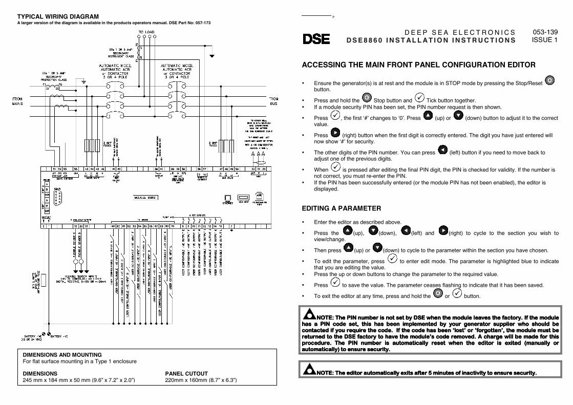
TYPICAL WIRING DIAGRAM A larger version of the diagram is available in the products operators manual. DSE Part No: 057-173
DIMENSIONS AND MOUNTING For flat surface mounting in a Type 1 enclosure to meet UL requirements DIMENSIONS 245 mm x 184 mm x 50 mm (9.6” x 7.2” x 2.0”)
PANEL CUTOUT 220mm x 160mm (8.7” x 6.3”)

2
DSE8860AUTO TRANSFER SWITCH & MAINS COLOUR CONTROL MODULE
DSEGenset®
The DSE8860 is an easy-to-usesingle or multi-mains controller withautomatic transfer switch capability.Designed to synchronise single ormultiple DSE8810s with single ormultiple mains (utility) supplies, theDSE8860 will automatically controlthe change over from mains (utility)to generator supply or run generatorsin synchronisation with the mains(utility) to provide no-break, peaklopping and peak shaving powersolutions.
The module can indicate operationalstatus and fault conditions on theLCD screen (multiple languagesavailable), by illuminated LED,audible sounder and SMSmessaging.
Comprehensive communicationsare also available via RS232, RS485& Ethernet for remote PC controland monitoring, and integration intobuilding management systems. The comprehensive event log willrecord up to 250 events to facilitatemaintenance.
An extensive number of fixed andflexible monitoring and protectionfeatures are included. Easyalteration of the sequences, timersand alarms can be made using theDSE PC Configuration SuiteSoftware. Selected configuration isalso available via the module’s frontpanel.
With all communication portscapable of being active at the sametime, the DSE8000 Series is ideal fora wide variety of demanding loadshare applications.
KEY LOAD SHARE FEATURES:• Peak lopping• Sequential set start• Manual voltage/frequency
adjustment• R.O.C.O.F. and vector shift• Generator load demand• Automatic hours run balancing• Mains (Utility) de-coupling• Mains (Utility) de-coupling
test mode• Bus failure detection• Volts and frequency matching.
FEATURES
ENVIRONMENTAL TESTING STANDARDS
ELECTRO MAGNETIC COMPATIBILITYBS EN 61000-6-2EMC Generic Immunity Standard for theIndustrial EnvironmentBS EN 61000-6-4EMC Generic Emission Standard for theIndustrial Environment
ELECTRICAL SAFETYBS EN 60950Safety of Information Technology Equipment,including Electrical Business Equipment
TEMPERATUREBS EN 60068-2-1Ab/Ae Cold Test -30oCBS EN 60068-2-2Bb/Be Dry Heat +70oC
VIBRATIONBS EN 60068-2-6Ten sweeps in each of three major axes5Hz to 8Hz @ +/-7.5mm, 8Hz to 500Hz @ 2gn
HUMIDITYBS EN 60068-2-30Db Damp Heat Cyclic 20/55oC @ 95% RH 48HoursBS EN 60068-2-78Cab Damp Heat Static 40oC @ 93% RH 48Hours
SHOCKBS EN 60068-2-27Three shocks in each of three major axes15gn in 11mS
DEGREES OF PROTECTIONPROVIDED BY ENCLOSURESBS EN 60529IP65 - Front of module when installed into thecontrol panel with the supplied sealing gasket.
COMPREHENSIVE FEATURE LIST TO SUIT A WIDEVARIETY OF LOAD SHARE APPLICATIONS
DSE2130DSE2131DSE2133DSE2157DSE2152DSE2548
1ph2ph3ph
1ph2ph3phN
RS232 ANDRS485
DSENET®
EXPANSIONUSBPORT
USBHOST
CONFIGURABLEINPUTS
DC POWER SUPPLY 8-35V
7
OTHER
ETHERNET
12
232 2 x 485
8
PCMODBUSMODEM
+
N/C VOLT FREEOUTPUTS
BUSSENSING
N/O VOLTFREE OUTPUT
MAINS (UTILITY) SENSING
VOLTSCURRENT
1ph2ph3phN
1ph1 1
ISSUE 1
DSE8860
ANALOGUESENDERS
DC OUTPUTS
LOADCURRENT
MSC
8x60 8x10 8x80 8x10 8x60

DEEP SEA ELECTRONICS PLC UKHighfield House, Hunmanby Industrial Estate, Hunmanby YO14 0PHTELEPHONE +44 (0) 1723 890099 FACSIMILE +44 (0) 1723 893303EMAIL [email protected] WEBSITE www.deepseaplc.com
DEEP SEA ELECTRONICS INC USA3230 Williams Avenue, Rockford, IL 61101-2668 USATELEPHONE +1 (815) 316 8706 FACSIMILE +1 (815) 316 8708EMAIL [email protected] WEBSITE www.deepseausa.com
055-139/7/12 (1)
KEY FEATURES• Colour LCD graphical display• Configurable digital inputs (12)• Configurable outputs (10)• Configurable flexible sender inputs
(2)• Comprehensive electrical
protection• Comprehensive loadshare
capabilities• Mains (utility) fail sensing• Multiple mains (utility) monitoring,
when using multiple DSE8860s• Peak lopping• Peak shaving• RS232, RS485 & Ethernet remote
communications• Modbus RTU/TCP support • Configurable display languages• Audible alarm• Reduced file transfer time• Fault condition notification to
a designated PC• Compatible with DSE8700 &
DSE8600 Series
• Front panel editing with PINprotection
• Configurable timers and alarms• Multiple date and time scheduler• Configurable event log (250)• Easy access diagnostic page• kW overload protection• Reverse power protection• Power monitoring (kW h, kV Ar, kV
A h, kV Ar h)• USB connectivity• Backed up real time clock• Fully configurable via DSE
Configuration Suite PC software• Advanced SMS messaging
(additional external modemrequired)
• Start & stop capability via SMSmessaging
• Additional display screens to helpwith modem diagnostics
• DSENet® expansion compatible• Integral PLC editor
KEY BENEFITS• Dual processor for improved
response• RS232, RS485 & Ethernet can be
used at the same time• High number of inputs and outputs• Worldwide language support• Data logging & trending• Harmonics display for clear
monitoring• Modules can be integrated into
building management systems(BMS)
• Licence-free PC software• IP65 rating (with supplied gasket)
offers increased resistance towater ingress
• PLC editor allows userconfigurable functions to meetspecific application requirements
RELATED MATERIALSTITLE PART NO’SDSE8860 Installation Instructions 053-139DSE8860 Operator Manual 057-173DSE8860 PC Configuration Suite Software Manual 057-174DSE8810 Data Sheet 055-116
DSE8860AUTO TRANSFER SWITCH & MAINS COLOUR CONTROL MODULE
®
DSEGenset
FEATURES
Registered in England & Wales No.01319649VAT No.316923457
Deep Sea Electronics Plc maintains a policy of continuous development and reserves the right to change thedetails shown on this data sheet without prior notice. The contents are intended for guidance only.
SPECIFICATION
DC SUPPLYCONTINUOUS VOLTAGE RATING8 V to 35 V Continuous
CRANKING DROPOUTSAble to survive 0 V for 50 mS, providing supply was at least 10 V before dropoutand supply recovers to 5 V. This is achieved without the need for internal batteries.LEDs and backlight will not be maintained during cranking.
MAXIMUM OPERATING CURRENT600 mA at 12 V, 300 mA at 24 V
MAXIMUM STANDBY CURRENT330 mA at 12 V, 160 mA at 24 V
MAINS (UTILITY) AND BUSVOLTAGE RANGE15 V to 333 V AC (L-N)
FREQUENCY RANGE3.5 Hz to 75 Hz
OUTPUTSOUTPUTS C & D8 A at 250 V AC (Volt free)
AUXILIARY OUTPUTS E,F,G,H,I,J,K & L2 A DC at supply voltage
DIMENSIONSOVERALL245 mm x 184 mm x 50 mm 9.6” x 7.2” x 2”
PANEL CUT-OUT220 mm x 160 mm8.7” x 6.3”
MAXIMUM PANEL THICKNESS8 mm0.3”
STORAGE TEMPERATURE RANGE-40 oC to +85 oC

DSE8860 Operators Manual ISSUE 1
DEEP SEA ELECTRONICS PLC
DSE8860 Controller Operators Manual
Document Number: 057-173
Author: Ashley Senior
DSE8860 Operators Manual
2
DEEP SEA ELECTRONICS PLC Highfield House Hunmanby North Yorkshire YO14 0PH ENGLAND Sales Tel: +44 (0) 1723 890099 Sales Fax: +44 (0) 1723 893303 E-mail : [email protected] Website : www.deepseaplc.com
DSE8860 Operators Manual © Deep Sea Electronics Plc All rights reserved. No part of this publication may be reproduced in any material form (including photocopying or storing in any medium by electronic means or other) without the written permission of the copyright holder except in accordance with the provisions of the Copyright, Designs and Patents Act 1988. Applications for the copyright holder’s written permission to reproduce any part of this publication should be addressed to Deep Sea Electronics Plc at the address above. The DSE logo is a UK registered trademarks of Deep Sea Electronics PLC. Any reference to trademarked product names used within this publication is owned by their respective companies. Deep Sea Electronics Plc reserves the right to change the contents of this document without prior notice. Amendments List
Issue Comments Minimum Module Version Required
1 Initial release Typeface: The typeface used in this document is Arial. Care should be taken not to mistake the upper case letter I with the numeral 1. The numeral 1 has a top serif to avoid this confusion. Clarification of notation used within this publication.
NOTE:NOTE:NOTE:NOTE:
HighHighHighHighlights an essential element of a procedure to ensure correctness.lights an essential element of a procedure to ensure correctness.lights an essential element of a procedure to ensure correctness.lights an essential element of a procedure to ensure correctness.
CAUTION!CAUTION!CAUTION!CAUTION!
Indicates a procedure or practice, which, if not strictly observed, could Indicates a procedure or practice, which, if not strictly observed, could Indicates a procedure or practice, which, if not strictly observed, could Indicates a procedure or practice, which, if not strictly observed, could result in damage or destruction of equipment.result in damage or destruction of equipment.result in damage or destruction of equipment.result in damage or destruction of equipment.
WARNING! WARNING! WARNING! WARNING!
Indicates a procedure or practice, which coIndicates a procedure or practice, which coIndicates a procedure or practice, which coIndicates a procedure or practice, which could result in injury to uld result in injury to uld result in injury to uld result in injury to personnel or loss of life if not followed correctly.personnel or loss of life if not followed correctly.personnel or loss of life if not followed correctly.personnel or loss of life if not followed correctly.
DSE8860 Operators Manual
3
TABLE OF CONTENTS Section Page 1 BIBLIOGRAPHY .............................................................................................. 7
1.1 INSTALLATION INSTRUCTIONS ....................................................................................... 7 1.2 TRAINING GUIDES ............................................................................................................. 7 1.3 MANUALS ........................................................................................................................... 8 1.4 THIRD PARTY DOCUMENTS ............................................................................................. 8
2 INTRODUCTION .............................................................................................. 9
3 SPECIFICATIONS .......................................................................................... 10 3.1 PART NUMBERING .......................................................................................................... 10
3.1.1 SHORT NAMES .......................................................................................................... 10 3.2 TERMINAL SPECIFICATION ............................................................................................ 10 3.3 POWER SUPPLY REQUIREMENTS ................................................................................ 11
3.3.1 PLANT SUPPLY INSTRUMENTATION DISPLAY ..................................................... 11 3.4 VOLTAGE / FREQUENCY SENSING ............................................................................... 11 3.5 CURRENT SENSING ........................................................................................................ 12
3.5.1 VA RATING OF THE CTS .......................................................................................... 12 3.5.2 CT POLARITY ............................................................................................................ 13 3.5.3 CT PHASING .............................................................................................................. 13 3.5.4 CT CLASS .................................................................................................................. 13
3.6 INPUTS .............................................................................................................................. 14 3.6.1 ANALOGUE INPUTS C & D ....................................................................................... 14
3.6.1.1 CONFIGURED AS DIGITAL INPUTS ................................................................. 14 3.6.1.2 CONFIGURED AS RESISTIVE SENSOR INPUTS ............................................ 14 3.6.1.3 CONFIGURED AS 0-10V INPUTS ...................................................................... 14 3.6.1.4 CONFIGURED AS 4-20MA INPUTS ................................................................... 14
3.6.2 DIGITAL INPUTS A, B, C, D, E, F, G, H, I, J, K & L ................................................... 15 3.7 OUTPUTS .......................................................................................................................... 15
3.7.1 VOLT FREE OUTPUTS C & D (LOAD SWITCHING) ................................................ 15 3.7.2 DIGITAL OUTPUTS E, F, G, H, I, J, K & L ................................................................. 15
3.8 COMMUNICATION PORTS .............................................................................................. 16 3.8.1 USB CONNECTION ................................................................................................... 17 3.8.2 USB HOST-MASTER (USB DRIVE CONNECTION) ................................................. 17 3.8.3 RS232 ......................................................................................................................... 18
3.8.3.1 RECOMMENDED PC RS232 SERIAL PORT ADD-ONS ................................... 18 3.8.3.2 RECOMMENDED EXTERNAL MODEMS: ......................................................... 19
3.8.4 RS485 ......................................................................................................................... 20 3.8.4.1 RECOMMENDED PC RS485 SERIAL PORT ADD-ONS ................................... 20
3.8.5 ETHERNET ................................................................................................................. 21 3.8.5.1 DIRECT PC CONNECTION ................................................................................ 22 3.8.5.2 CONNECTION TO BASIC ETHERNET .............................................................. 23 3.8.5.3 CONNECTION TO COMPANY INFRASTRUCTURE ETHERNET..................... 24 3.8.5.4 CONNECTION TO THE INTERNET ................................................................... 25 3.8.5.5 FIREWALL CONFIGURATION FOR INTERNET ACCESS ................................ 26
3.9 DSENET® FOR EXPANSION MODULES ....................................................................... 27 3.10 SOUNDER ...................................................................................................................... 28
3.10.1 ADDING AN EXTERNAL SOUNDER TO THE APPLICATION .................................. 28 3.11 ACCUMULATED INSTRUMENTATION ........................................................................ 28 3.12 DIMENSIONS AND MOUNTING ................................................................................... 29
3.12.1 DIMENSIONS ............................................................................................................. 29 3.12.2 PANEL CUTOUT ........................................................................................................ 29 3.12.3 WEIGHT ..................................................................................................................... 29 3.12.4 FIXING CLIPS ............................................................................................................. 29 3.12.5 CABLE TIE FIXING POINTS ...................................................................................... 30 3.12.6 SILICON SEALING GASKET ..................................................................................... 30
DSE8860 Operators Manual
4
3.13 APPLICABLE STANDARDS ......................................................................................... 31 3.13.1 BS, UL AND IEEE CLASSIFICATIONS ...................................................................... 31 3.13.2 ENCLOSURE CLASSIFICATIONS ............................................................................. 33 3.13.3 NEMA CLASSIFICATIONS ......................................................................................... 34
4 INSTALLATION ............................................................................................. 35 4.1 USER CONNECTIONS ...................................................................................................... 35 4.2 TERMINAL DESCRIPTION ............................................................................................... 36
4.2.1 DC SUPPLY, FUEL AND START OUTPUTS, OUTPUTS E-J ................................... 36 4.2.2 ANALOGUE SENSOR ................................................................................................ 36 4.2.3 MAGNETIC PICKUP, CAN AND EXPANSION .......................................................... 37 4.2.4 LOAD SWITCHING AND V1 MAINS VOLTAGE SENSING ....................................... 38 4.2.5 V2 BUS VOLTAGE SENSING .................................................................................... 38 4.2.6 MAINS CURRENT TRANSFORMERS ....................................................................... 39 4.2.7 BUS/LOAD CURRENT TRANSFORMER .................................................................. 40
4.2.7.1 ADVANTAGES OF BUS/LOAD CT ..................................................................... 40 4.2.8 CONFIGURABLE DIGITAL INPUTS .......................................................................... 41 4.2.9 PC CONFIGURATION INTERFACE CONNECTOR .................................................. 41 4.2.10 RS232 CONNECTOR ................................................................................................. 42 4.2.11 RS485 CONNECTOR ................................................................................................. 42 4.2.12 ETHERNET ................................................................................................................. 42
4.3 TYPICAL WIRING DIAGRAM (3 PHASE, 4 WIRE STAR)................................................ 43 4.3.1 ALTERNATE TOPOLOGIES ...................................................................................... 44
4.3.1.1 SINGLE PHASE, 2 WIRE .................................................................................... 44 4.3.1.2 2 PHASE (L1 & L2), 3 WIRE DELTA ................................................................... 45 4.3.1.3 2 PHASE (L1 & L3), 3 WIRE DELTA ................................................................... 45 4.3.1.4 3 PHASE, 3 WIRE DELTA .................................................................................. 46 4.3.1.5 3 PHASE, 4 WIRE DELTA .................................................................................. 46
4.3.2 BUS AND LOAD CURRENT TRANSFORMER POSITION ....................................... 47 4.3.2.1 3 PHASE, 4 WIRE WITH A BUS CURRENT TRANSFORMER ......................... 47 4.3.2.2 3 PHASE, 4 WIRE WITH A LOAD CURRENT TRANSFORMER ....................... 48
4.3.3 TYPICAL SYSTEM SCHEMATICS ............................................................................. 49 4.3.3.1 SINGLE MAINS, MULTIPLE GENERATORS ..................................................... 49 4.3.3.2 DUAL MAINS, MULTIPLE GENERATORS ......................................................... 50 4.3.3.3 MULTIPLE MAINS, MULTIPLE GENERATORS ................................................. 51
4.4 EARTH SYSTEMS ............................................................................................................. 52 4.4.1 NEGATIVE EARTH ..................................................................................................... 52 4.4.2 POSITIVE EARTH ...................................................................................................... 52 4.4.3 FLOATING EARTH ..................................................................................................... 52
4.5 TYPICAL ARRANGEMENT OF DSENET® ...................................................................... 53
5 DESCRIPTION OF CONTROLS .................................................................... 54 5.1 DSE8860 AUTO START CONTROL MODULE ................................................................ 54 5.2 QUICKSTART GUIDE ....................................................................................................... 55
5.2.1 STARTING THE GENERATOR(S) ............................................................................. 55 5.2.2 STOPPING THE ENGINE .......................................................................................... 55
5.3 VIEWING THE INSTRUMENT PAGES ............................................................................. 56 5.3.1 DISPLAY OVERVIEW ................................................................................................ 56 5.3.2 PAGE INDICATORS ................................................................................................... 56 5.3.3 SIDE SCROLL BAR .................................................................................................... 57 5.3.4 SUMMARY AREA ....................................................................................................... 57
5.3.4.1 WHEN CONFIGURED TO SHOW LOAD SWITCH ........................................... 57 5.3.4.2 WHEN CONFIGURED TO SHOW BAR GRAPHS ............................................. 57 5.3.4.3 DURING SYNCHRONISING ............................................................................... 57
5.3.5 HOME ......................................................................................................................... 58 5.3.6 MAINS ......................................................................................................................... 60 5.3.7 BUS ............................................................................................................................. 62 5.3.8 I/O ............................................................................................................................... 64 5.3.9 ALARMS ..................................................................................................................... 65 5.3.10 SCHEDULE ................................................................................................................ 66 5.3.11 STATUS ...................................................................................................................... 66

DSE8860 Operators Manual
5
6 FACIA OPERATION ....................................................................................... 71 6.1 CONTROL ......................................................................................................................... 71 6.2 CONTROL PUSH-BUTTONS ............................................................................................ 72
7 OPERATING PROCEDURE .......................................................................... 74 7.1 STOP MODE ...................................................................................................................... 74 7.2 AUTOMATIC MODE .......................................................................................................... 75
7.2.1 WAITING IN AUTO MODE ......................................................................................... 75 7.2.2 STARTING SEQUENCE............................................................................................. 75 7.2.3 BUS AVAILABLE (GENERATOR(S) RUNNING) ....................................................... 76
7.2.3.1 BUS MODE .......................................................................................................... 76 7.2.3.2 MAINS MODE ...................................................................................................... 76
7.2.4 STOPPING SEQUENCE ............................................................................................ 76 7.3 MANUAL MODE ................................................................................................................ 77
7.3.1 WAITING IN MANUAL MODE .................................................................................... 77 7.3.2 BUS AVAILABLE (GENERATOR(S) RUNNING) ....................................................... 77 7.3.3 STOPPING SEQUENCE ............................................................................................ 77
7.4 TEST MODE ...................................................................................................................... 78 7.4.1 WAITING IN TEST MODE .......................................................................................... 78 7.4.2 BUS AVAILABLE (GENERATOR(S) RUNNING) ....................................................... 78
7.5 MULTIPLE MAINS OPERATION ...................................................................................... 79 7.5.1 DSE8X60 PRIORITY .................................................................................................. 79 7.5.2 DSE8860 BUS/LOAD CT ............................................................................................ 80
8 PROTECTIONS .............................................................................................. 81 8.1 INDICATIONS .................................................................................................................... 81 8.2 WARNINGS ....................................................................................................................... 82 8.3 ELECTRICAL TRIPS ......................................................................................................... 84 8.4 ROCOF / VECTOR SHIFT ................................................................................................. 86
9 SCHEDULER ................................................................................................. 87 9.1.1 STOP MODE .............................................................................................................. 87 9.1.2 MANUAL MODE ......................................................................................................... 87 9.1.3 AUTO MODE .............................................................................................................. 87
10 FRONT PANEL CONFIGURATION ............................................................ 88 10.1 ACCESSING THE MAIN FRONT PANEL CONFIGURATION EDITOR ....................... 89
10.1.1 EDITING A PARAMETER ........................................................................................... 89 10.1.2 ADJUSTABLE PARAMETERS ................................................................................... 90
10.2 ACCESSING THE ‘MAINTENANCE’ CONFIGURATION EDITOR .............................. 91 10.2.1 EDITING A PARAMETER ........................................................................................... 91 10.2.2 ADJUSTABLE PARAMETERS ................................................................................... 91
10.3 ACCESSING THE ‘RUNNING’ CONFIGURATION EDITOR ........................................ 92 10.3.1 EDITING A PARAMETER ........................................................................................... 92 10.3.2 ADJUSTABLE PARAMETERS ................................................................................... 92
11 COMMISSIONING ....................................................................................... 93 11.1 PRE-COMMISSIONING ................................................................................................. 93
12 FAULT FINDING ......................................................................................... 94 12.1 STARTING ..................................................................................................................... 94 12.2 LOADING ....................................................................................................................... 94 12.3 COMMUNICATIONS ...................................................................................................... 95 12.4 INSTRUMENTS ............................................................................................................. 96 12.5 MISCELLANEOUS ........................................................................................................ 96
13 DSE 4 STEPS TO SUCCESSFUL SYNCHRONISING ............................... 97 13.1 CONTROL ...................................................................................................................... 97 13.2 METERING..................................................................................................................... 97 13.3 COMMUNICATIONS ...................................................................................................... 97 13.4 SYNC CHECKS ............................................................................................................. 97

DSE8860 Operators Manual
6
14 MAINTENANCE, SPARES, REPAIR AND SERVICING ............................. 98 14.1 PURCHASING ADDITIONAL CONNECTOR PLUGS FROM DSE ............................... 98
14.1.1 PACK OF PLUGS ....................................................................................................... 98 14.1.2 INDIVIDUAL PLUGS ................................................................................................... 98
14.2 PURCHASING ADDITIONAL FIXING CLIPS FROM DSE ............................................ 98 14.3 PURCHASING ADDITIONAL SEALING GASKET FROM DSE ................................... 98 14.4 DSENET EXPANSION MODULES ................................................................................ 99
15 WARRANTY .............................................................................................. 100
16 DISPOSAL ................................................................................................ 100 16.1 WEEE (WASTE ELECTRICAL AND ELECTRONIC EQUIPMENT) ........................... 100 16.2 ROHS (RESTRICTION OF HAZARDOUS SUBSTANCES) ........................................ 100

Bibliography
7
1 BIBLIOGRAPHY
This document refers to and is referred to by the following DSE publications which can be obtained from the DSE website: www.deepseaplc.com 1.1 INSTALLATION INSTRUCTIONS Installation instructions are supplied with the product in the box and are intended as a ‘quick start’ guide only. DSE PART DESCRIPTION 053-137 DSE8810 Installation Instructions 053-139 DSE8860 Installation Instructions 053-032 DSE2548 LED Expansion Annunciator Installation Instructions 053-033 DSE2130 Input Expansion Installation Instructions 053-034 DSE2157 Output Expansion Installation Instructions 053-125 DSE2131 Ratiometric Input Expansion Installation Instructions 053-126 DSE2133 RTD/Thermocouple Input Expansion Installation Instructions 053-134 DSE2152 Ratio-metric Output Expansion Installation Instructions 1.2 TRAINING GUIDES Training Guides are produced to give ‘handout’ sheets on specific subjects during training sessions DSE PART DESCRIPTION 056-005 Using CTs With DSE Products 056-006 Introduction to Comms 056-010 Overcurrent Protection 056-013 Load Demand Scheme 056-018 Negative Phase Sequence 056-019 Earth Fault Protection 056-020 Loss of Excitation 056-021 Mains Decoupling 056-022 Breaker Control 056-024 GSM Modem 056-026 kW & kVAr 056-030 Module PIN Codes 056-032 xx60 With No Bus Breaker 056-042 Bus or Mains Mode

Bibliography
8
1.3 MANUALS Product manuals are can be downloaded from the DSE website: www.deepseaplc.com DSE PART DESCRIPTION 057-045 Guide to Synchronising and Load Sharing Part 1 057-046 Guide to Synchronising and Load Sharing Part 2 057-047 Load Share Design and Commissioning Guide 057-164 DSE8810 PC Software Configuration Manual 057-174 DSE8860 PC Software Configuration Manual 057-082 DSE2130 Input Expansion Manual 057-083 DSE2157 Output Expansion Manual 057-084 DSE2548 Annunciator Expansion Manual 057-139 DSE2131 Ratio-metric Input Expansion Manual 057-140 DSE2133 RTD/Thermocouple Expansion Manual 057-141 DSE2152 Ratio-metric Output Expansion Manual 1.4 THIRD PARTY DOCUMENTS The following third party documents are also referred to: REFERENCE DESCRIPTION ISBN 1-55937-879-4 IEEE Std C37.2-1996 IEEE Standard Electrical Power System Device Function
Numbers and Contact Designations. Institute of Electrical and Electronics Engineers Inc ISBN 0-7506-1147-2 Diesel generator handbook. L.L.J.Mahon ISBN 0-9625949-3-8 On-Site Power Generation. EGSA Education Committee.
Introduction
9
2 INTRODUCTION This document details the installation and operation requirements of the DSE8860 module, part of the DSEGenset® range of products. The manual forms part of the product and should be kept for the entire life of the product. If the product is passed or supplied to another party, ensure that this document is passed to them for reference purposes. This is not a controlled document. You will not be automatically informed of updates. Any future updates of this document will be included on the DSE website at www.deepseaplc.com The DSE8860 is designed to provide differing levels of functionality across a common platform. This allows the generator OEM greater flexibility in the choice of controller to use for a specific application. The DSE8860 module has been designed to monitor the mains (utility) supply and automatically start/stop one or more generator sets equipped with DSE8x10 controllers depending upon the status of the mains (utility) supply. Synchronising and Load Sharing features are included within the controller, along with the necessary protections for such a system. This provides forward sync, back sync (no break changeover) and start/stop upon changing load levels. The user also has the facility to view the system operating parameters via the LCD display. The powerful ARM microprocessor contained within the module allows for incorporation of a range of complex features: • Text and graphical colour LCD display (supporting multiple languages). • True RMS Voltage, Current and Power monitoring with minimum and maximum ranges • Harmonic Display • Communications capability (USB, RS232, RS485 and Ethernet) • Event log and instrumentation data log • Fully configurable inputs for use as alarms or a range of different functions. • Synchronising and load sharing with load demand start/stop • R.O.C.O.F. and Vector shift for detection of mains failure when in parallel with the mains supply. • Integral PLC to help provide customisation where required Using a PC and the DSE Configuration Suite software allows alteration of selected operational sequences, timers, alarms and operational sequences. Additionally, the module’s integral fascia configuration editor allows adjustment of a subset of this information. A robust plastic case designed for front panel mounting houses the module. Connections are via locking plug and sockets.

Specification
10
3 SPECIFICATIONS 3.1 PART NUMBERING
8860 - 001 - 01 At the time of this document production, there have been no revisions to the module hardware. 3.1.1 SHORT NAMES Short Name Description DSE8000,DSE8xxx All modules in the DSE8000 range. DSE8800,DSE88xx All modules in the DSE8800 range. 3.2 TERMINAL SPECIFICATION
Connection Type
Two part connector. • Male part fitted to module • Female part supplied in
module packing case - Screw terminal, rising clamp, no internal spring.
Example showing cable entry and screw terminals of a 10 way connector Minimum Cable Size 0.5 mm² (AWG 24)
Maximum Cable Size 2.5 mm² (AWG 10)
NOTE:NOTE:NOTE:NOTE: For purchasing additional connector plugs from DSE, please see the section For purchasing additional connector plugs from DSE, please see the section For purchasing additional connector plugs from DSE, please see the section For purchasing additional connector plugs from DSE, please see the section entitled Maintenance, Spares, Repair and Servicing elsewhere in this doentitled Maintenance, Spares, Repair and Servicing elsewhere in this doentitled Maintenance, Spares, Repair and Servicing elsewhere in this doentitled Maintenance, Spares, Repair and Servicing elsewhere in this document.cument.cument.cument.
Product type
DSE8860 ATS and Mains Controller
8860
Variant
Standard version 01
Hardware revision
Initial Release 001
UL approved version 32
Specification
11
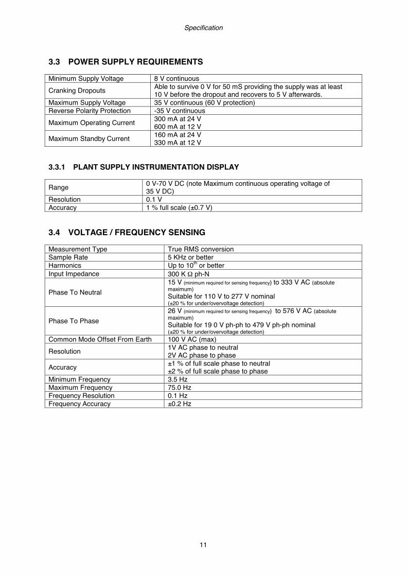
3.3 POWER SUPPLY REQUIREMENTS Minimum Supply Voltage 8 V continuous Cranking Dropouts Able to survive 0 V for 50 mS providing the supply was at least
10 V before the dropout and recovers to 5 V afterwards. Maximum Supply Voltage 35 V continuous (60 V protection) Reverse Polarity Protection -35 V continuous Maximum Operating Current 300 mA at 24 V
600 mA at 12 V Maximum Standby Current 160 mA at 24 V
330 mA at 12 V 3.3.1 PLANT SUPPLY INSTRUMENTATION DISPLAY Range 0 V-70 V DC (note Maximum continuous operating voltage of
35 V DC) Resolution 0.1 V Accuracy 1 % full scale (±0.7 V) 3.4 VOLTAGE / FREQUENCY SENSING Measurement Type True RMS conversion Sample Rate 5 KHz or better Harmonics Up to 10th or better Input Impedance 300 K Ω ph-N
Phase To Neutral 15 V (minimum required for sensing frequency) to 333 V AC (absolute maximum) Suitable for 110 V to 277 V nominal (±20 % for under/overvoltage detection)
Phase To Phase 26 V (minimum required for sensing frequency) to 576 V AC (absolute maximum) Suitable for 19 0 V ph-ph to 479 V ph-ph nominal (±20 % for under/overvoltage detection)
Common Mode Offset From Earth 100 V AC (max) Resolution 1V AC phase to neutral
2V AC phase to phase Accuracy ±1 % of full scale phase to neutral
±2 % of full scale phase to phase Minimum Frequency 3.5 Hz Maximum Frequency 75.0 Hz Frequency Resolution 0.1 Hz Frequency Accuracy ±0.2 Hz

Specification
12
3.5 CURRENT SENSING Measurement Type True RMS conversion Sample Rate 5 kHz or better Harmonics Up to 10th or better Nominal CT Secondary Rating 1 A or 5 A (5 A recommended) Maximum Continuous Current 5 A Overload Measurement 3 x Nominal Range setting Absolute Maximum Overload 50 A for 1 second Burden 0.5 VA (0.02 Ω current shunts) Common Mode Offset ±2 V peak plant ground to CT common terminal Resolution 0.5 % of 5 A Accuracy ±1 % of Nominal (1 A or 5 A) (excluding CT error) 3.5.1 VA RATING OF THE CTS The VA burden of the module on the CTs is 0.5 VA. However depending upon the type and length of cabling between the CTs and the module, CTs with a greater VA rating than the module are required. The distance between the CTs and the measuring module should be estimated and cross-referenced against the chart opposite to find the VA burden of the cable itself. If the CTs are fitted within the alternator top box, the star point (common) of the CTs should be connected to system ground (earth) as close as possible to the CTs. This minimises the length of cable used to connect the CTs to the DSE module. Example If 1.5 mm² cable is used and the distance from the CT to the measuring module is 20 m, then the burden of the cable alone is approximately 15 VA. As the burden of the DSE controller is 0.5 VA, then a CT with a rating of at least 15+0.5 V = 15.5 VA must be used. If 2.5 mm² cables are used over the same distance of 20 m, then the burden of the cable on the CT is approximately 7 VA. CT’s required in this instance is at least 7.5 VA (7+0.5).
NOTE:NOTE:NOTE:NOTE: Details for 4Details for 4Details for 4Details for 4 mm² cables are shown for reference only. The connectors on the mm² cables are shown for reference only. The connectors on the mm² cables are shown for reference only. The connectors on the mm² cables are shown for reference only. The connectors on the DDDDSE modules are only suitable for cables up to 2.5SE modules are only suitable for cables up to 2.5SE modules are only suitable for cables up to 2.5SE modules are only suitable for cables up to 2.5 mm².mm².mm².mm².
NOTE:NOTE:NOTE:NOTE: CTs with 5CTs with 5CTs with 5CTs with 5 A secondary windings are recommended with DSE modules. 1A secondary windings are recommended with DSE modules. 1A secondary windings are recommended with DSE modules. 1A secondary windings are recommended with DSE modules. 1 A CTs A CTs A CTs A CTs can be used if necessary however, the resolution of the readings is 5 times better when can be used if necessary however, the resolution of the readings is 5 times better when can be used if necessary however, the resolution of the readings is 5 times better when can be used if necessary however, the resolution of the readings is 5 times better when using 5using 5using 5using 5 A CTs.A CTs.A CTs.A CTs.

Specification
13
3.5.2 CT POLARITY Take care to ensure the correct polarity of the CTs. Incorrect CT orientation will lead to negative kW readings when the set is supplying power. Take note that paper stick-on labels on CTs that show the orientation are often incorrectly placed on the CT (!). It is more reliable to use the labelling in the case moulding as an indicator to orientation (if available). To test orientation, run the generator in island mode (not in parallel with any other supply) and load the generator to around 10 % of the set rating. Ensure the DSE module shows positive kW for all three individual phase readings.
TO MAINS
TO LOAD SWITCH DEVICE
POLARITY OF CT PRIMARY
NOTE:NOTE:NOTE:NOTE: Take care to ensure correct polarity of the CT primary as shown above. If in Take care to ensure correct polarity of the CT primary as shown above. If in Take care to ensure correct polarity of the CT primary as shown above. If in Take care to ensure correct polarity of the CT primary as shown above. If in doubt, checdoubt, checdoubt, checdoubt, check with the CT supplier.k with the CT supplier.k with the CT supplier.k with the CT supplier.
3.5.3 CT PHASING Take particular care that the CTs are connected to the correct phases. For instance, ensure that the CT on phase 1 is connected to the terminal on the DSE module intended for connection to the CT for phase 1. Additionally ensure that the voltage sensing for phase 1 is actually connected to generator phase 1. Incorrect connection of the phases as described above will result in incorrect power factor (pf) measurements, which in turn results in incorrect kW measurements. One way to check for this is to make use of a single-phase load. Place the load on each phase in turn, run the generator and ensure the kW value appears in the correct phase. For instance if the load is connected to phase 3, ensure the kW figure appears in phase 3 display and not in the display for phase 1 or 2. 3.5.4 CT CLASS
Ensure the correct CT type is chosen. For instance if the DSE module is providing overcurrent protection, ensure the CT is capable of measuring the overload level you wish to protect against, and at the accuracy level you require. For instance, this may mean fitting a protection class CT (P10 type) to maintain high accuracy while the CT is measuring overload currents. Conversely, if the DSE module is using the CT for instrumentation only (current protection is disabled or not fitted to the controller), then measurement class CTs can be used. Again, bear in mind the accuracy you require. The DSE module is accurate to better than 1% of the full-scale current reading. To maintain this accuracy you should fit Class 0.5 or Class 1 CTs. You should check with your CT manufacturer for further advice on selecting your CTs
labelled as p1, k or K
labelled as p2, l or L

Specification
14
3.6 INPUTS 3.6.1 ANALOGUE INPUTS C & D
NOTE:NOTE:NOTE:NOTE: Refer to DSE8860 PC Software Configuration Manual (DSE part 057Refer to DSE8860 PC Software Configuration Manual (DSE part 057Refer to DSE8860 PC Software Configuration Manual (DSE part 057Refer to DSE8860 PC Software Configuration Manual (DSE part 057----174)174)174)174) for for for for further detailfurther detailfurther detailfurther details on configuring, monitoring and control.s on configuring, monitoring and control.s on configuring, monitoring and control.s on configuring, monitoring and control.
3.6.1.1 CONFIGURED AS DIGITAL INPUTS Arrangement Contact between input terminal and the analogue common. Low Level Threshold 2.1V minimum High Level Threshold 6.6V maximum Max Input Voltage +60V DC with respect to battery negative Min Input Voltage -24V DC with respect to battery negative Contact Wetting Current 7mA typical Open Circuit Voltage Plant supply typical 3.6.1.2 CONFIGURED AS RESISTIVE SENSOR INPUTS Arrangement Contact between input terminal and the analogue common. Measurement Current 9.3mA typical Full Scale 480Ω Sensor Fail Values greater than full scale return an over range sentinel that may be
interpreted as sensor fail if appropriate (host controller dependant) Resolution 1% of full scale Accuracy ±2% of full scale resistance, excluding transducer (sensor) error Maximum Common Mode Voltage 3V Transducer (Sensor Type) Configurable in host controller 3.6.1.3 CONFIGURED AS 0-10V INPUTS Arrangement Contact between input terminal and the analogue common. Measureable Range 0V DC to 10V DC Sensor Fail Values greater than full scale return an over range sentinel that may be
interpreted as sensor fail if appropriate. Internal Impedance Greater than 10kΩ External Impedance 0 to 3kΩ Resolution 1% of full scale Accuracy ±1% of full scale voltage, excluding transducer (sensor) error Transducer (Sensor Type) Configurable in host controller 3.6.1.4 CONFIGURED AS 4-20MA INPUTS Arrangement Contact between input terminal and the analogue common. Measureable Range 0mA DC to 20mA DC Sensor Fail Values greater than full scale return an over range sentinel that may be
interpreted as sensor fail if appropriate. Internal Sense Resistor 240Ω External Impedance 0 to 3kΩ Resolution 1% of full scale Accuracy ±1% of full scale current, excluding transducer (sensor) error Transducer (Sensor Type) Configurable in host controller

Specification
15
3.6.2 DIGITAL INPUTS A, B, C, D, E, F, G, H, I, J, K & L
NOTE:NOTE:NOTE:NOTE: Refer to DSE8860 PC Software Configuration Manual (DSE part 057Refer to DSE8860 PC Software Configuration Manual (DSE part 057Refer to DSE8860 PC Software Configuration Manual (DSE part 057Refer to DSE8860 PC Software Configuration Manual (DSE part 057----174)174)174)174) for for for for further defurther defurther defurther details on configuring, monitoring and control.tails on configuring, monitoring and control.tails on configuring, monitoring and control.tails on configuring, monitoring and control.
Number 12 configurable digital inputs. Arrangement Contact between terminal and ground Low Level Threshold 2.1 V minimum High Level Threshold 6.6 V maximum Maximum Input Voltage +50 V DC with respect to plant supply negative Minimum Input Voltage -24 V DC with respect to plant supply negative Contact Wetting Current 7 mA typical Open Circuit Voltage Plant supply typical 3.7 OUTPUTS Ten (10) outputs are fitted to the controller.
NOTE:NOTE:NOTE:NOTE: Refer to DSE8860 Refer to DSE8860 Refer to DSE8860 Refer to DSE8860 PC Software Configuration Manual (DSE part 057PC Software Configuration Manual (DSE part 057PC Software Configuration Manual (DSE part 057PC Software Configuration Manual (DSE part 057----174)174)174)174) for for for for further details on configuring, monitoring and control.further details on configuring, monitoring and control.further details on configuring, monitoring and control.further details on configuring, monitoring and control.
3.7.1 VOLT FREE OUTPUTS C & D (LOAD SWITCHING)
Type Two (2) fully configurable volts free relays. Output C: Normally Closed Output D: Normally Open
Rating 8A resistive@ 250V AC Protection Protected against over current & over temperature. Built in load dump feature. 3.7.2 DIGITAL OUTPUTS E, F, G, H, I, J, K & L Number Eight (8) configurable DC outputs. Type Fully configurable, supplied from DC supply terminal 2. Rating 2A resistive at plant supply voltage. Open Circuit Voltage Plant supply typical.

Specification
16
3.8 COMMUNICATION PORTS
NOTE:NOTE:NOTE:NOTE: Refer to DSE8860 PC Software Configuration Manual (DSE part 057Refer to DSE8860 PC Software Configuration Manual (DSE part 057Refer to DSE8860 PC Software Configuration Manual (DSE part 057Refer to DSE8860 PC Software Configuration Manual (DSE part 057----174)174)174)174) for for for for further details on configuring, monitoring andfurther details on configuring, monitoring andfurther details on configuring, monitoring andfurther details on configuring, monitoring and control.control.control.control.
USB Port USB2.0 Device for connection to PC running DSE configuration suite only Max distance 6m (yards)
RS232 Serial port
Non – Isolated port Max Baud rate 115K baud subject to configuration TX, RX, RTS, CTS, DSR, DTR, DCD Male 9 way D type connector Max distance 15m (50 feet)
2 x RS485 Serial ports
Isolated Data connection 2 wire + common Half Duplex Data direction control for Transmit (by s/w protocol) Max Baud rate 115K baud subject to configuration External termination required (120Ω) Max common mode offset 70V (on board protection transorb) Max distance 1.2km (¾ mile)
Ethernet Auto detecting 10/100 Ethernet port.

Specification
17
3.8.1 USB CONNECTION The USB port is provided to give a simple means of connection between a PC and the controller. Using the DSE Configuration Suite Software, the operator is then able to control the module, starting or stopping the generator, selecting operating modes, etc. Additionally, the various operating parameters (such as output volts, oil pressure, etc.) of the remote generator are available to be viewed or changed. To connect a module to a PC by USB, the following items are required:
• DSE8800 series module
• DSE Configuration Suite PC Software (Supplied on configuration suite software CD or available from www.deepseaplc.com).
• USB cable Type A to Type B. (This is the same cable as often used between a PC and a USB printer) DSE can supply this cable if required : PC Configuration interface lead (USB type A – type B) DSE Part No 016-125
NOTE:NOTE:NOTE:NOTE: The DC supply The DC supply The DC supply The DC supply must be connected to the module for configuration by PC.must be connected to the module for configuration by PC.must be connected to the module for configuration by PC.must be connected to the module for configuration by PC.
NOTE:NOTE:NOTE:NOTE: Refer to DSE8860 PC Software Configuration Manual (DSE part 057Refer to DSE8860 PC Software Configuration Manual (DSE part 057Refer to DSE8860 PC Software Configuration Manual (DSE part 057Refer to DSE8860 PC Software Configuration Manual (DSE part 057----174)174)174)174) for for for for further details on configuring, monitoring and control.further details on configuring, monitoring and control.further details on configuring, monitoring and control.further details on configuring, monitoring and control.
3.8.2 USB HOST-MASTER (USB DRIVE CONNECTION) USB Type A connection for USB Host facility which is used to connected an external USB storage device for the Data Logging feature. Maximum size of externally storage device can be 16 GB (see viewing the instrument pages).
NOTE:NOTE:NOTE:NOTE: Refer to DSE8860 PC Software Configuration MaRefer to DSE8860 PC Software Configuration MaRefer to DSE8860 PC Software Configuration MaRefer to DSE8860 PC Software Configuration Manual (DSE part 057nual (DSE part 057nual (DSE part 057nual (DSE part 057----174)174)174)174) for for for for further details on configuring, monitoring and control.further details on configuring, monitoring and control.further details on configuring, monitoring and control.further details on configuring, monitoring and control.

Specification
18
3.8.3 RS232 The RS232 port on the controller supports the Modbus RTU protocol. The Gencomm register table for the controller is available upon request from the DSE Technical Support Department. RS232 is for short distance communication (max 15m) and is typically used to connect the controller to a telephone or GSM modem for more remote communications. Many PCs are not fitted with an internal RS232 serial port. DSE DO NOT recommend the use of USB to RS232 convertors but can recommend PC add-ons to provide the computer with an RS232 port. 3.8.3.1 RECOMMENDED PC RS232 SERIAL PORT ADD-ONS Remember to check these parts are suitable for your PC. Consult your PC supplier for further advice.
• Brainboxes PM143 PCMCIA RS232 card (for laptop PCs)
• Brainboxes VX-001 Express Card RS232 (for laptops and nettops PCs)
• Brainboxes UC246 PCI RS232 card (for desktop PCs)
• Brainboxes PX-246 PCI Express 1 Port RS232 1 x 9 Pin (for desktop PCs)
Supplier: Brainboxes Tel: +44 (0)151 220 2500 Web: http://www.brainboxes.com Email: Sales: [email protected] NB DSE Have no business tie to Brainboxes. Over many years, our own engineers have used these products and are happy to recommend them.

Specification
19
3.8.3.2 RECOMMENDED EXTERNAL MODEMS:
• Multitech Global Modem – MultiModem ZBA (PSTN) DSE Part Number 020-252 (Contact DSE Sales for details of localisation kits for these modems)
• Sierra Fastrak Xtend GSM modem kit (PSU, Antenna and modem)* DSE Part number 0830-001-01
NOTE: *For GSM modems a SIM caNOTE: *For GSM modems a SIM caNOTE: *For GSM modems a SIM caNOTE: *For GSM modems a SIM card is required, supplied by your GSM network rd is required, supplied by your GSM network rd is required, supplied by your GSM network rd is required, supplied by your GSM network providerproviderproviderprovider
• For SMS only, a ‘normal’ voice SIM card is required. This enables the controller to send SMS
messages to designated mobile phones upon status and alarm conditions. • For a data connection to a PC running DSE Configuration Suite Software, a ‘special’ CSD
(Circuit Switched Data) SIM card is required that will enable the modem to answer an incoming data call. Many ‘pay as you go’ services will not provide a CSD (Circuit Switched Data) SIM card.

Specification
20
3.8.4 RS485 The RS485 ports on the controller support the Modbus RTU protocol. The DSE Gencomm register table for the controller is available upon request from the DSE Technical Support Department. RS485 is used for point-to-point cable connection of more than one device (maximum 32 devices) and allows for connection to PCs, PLCs and Building Management Systems (to name just a few devices). One advantage of the RS485 interface is the large distance specification (1.2km when using Belden 9841 (or equivalent) cable. This allows for a large distance between the module and a PC running the DSE Configuration Suite software. The operator is then able to control the module, starting or stopping the generator, selecting operating modes, etc. The various operating parameters (such as output volts, oil pressure, etc.) of the remote generator can be viewed or changed.
NOTE:NOTE:NOTE:NOTE: For a single module to PC connection and distances up to 6m (8yds) the USB For a single module to PC connection and distances up to 6m (8yds) the USB For a single module to PC connection and distances up to 6m (8yds) the USB For a single module to PC connection and distances up to 6m (8yds) the USB connection method is more suitable and provides for a lower cost alternative to RS4connection method is more suitable and provides for a lower cost alternative to RS4connection method is more suitable and provides for a lower cost alternative to RS4connection method is more suitable and provides for a lower cost alternative to RS485 85 85 85 (which is (which is (which is (which is more suited to longer distance more suited to longer distance more suited to longer distance more suited to longer distance connections).connections).connections).connections).
3.8.4.1 RECOMMENDED PC RS485 SERIAL PORT ADD-ONS Remember to check these parts are suitable for your PC. Consult your PC supplier for further advice.
• Brainboxes PM154 PCMCIA RS485 card (for laptops PCs) Set to ‘Half Duplex, Autogating” with ‘CTS True’ set to ‘enabled’
• Brainboxes VX-023 ExpressCard 1 Port RS422/485 (for laptops and nettop PCs)
• Brainboxes UC320 PCI Velocity RS485 card (for desktop PCs) Set to ‘Half Duplex, Autogating” with ‘CTS True’ set to ‘enabled’
• Brainboxes PX-324 PCI Express 1 Port RS422/485 (for desktop PCs)
Supplier: Brainboxes Tel: +44 (0)151 220 2500 Web: http://www.brainboxes.com Email: Sales: [email protected] NB DSE have no business tie to Brainboxes. Over many years,our own engineers have used these products and are happy to recommend them.
Specification
21
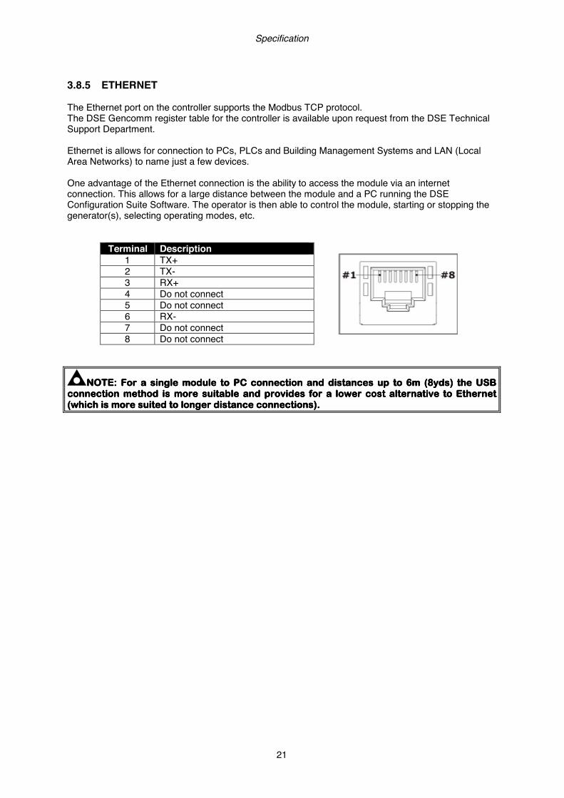
3.8.5 ETHERNET The Ethernet port on the controller supports the Modbus TCP protocol. The DSE Gencomm register table for the controller is available upon request from the DSE Technical Support Department. Ethernet is allows for connection to PCs, PLCs and Building Management Systems and LAN (Local Area Networks) to name just a few devices. One advantage of the Ethernet connection is the ability to access the module via an internet connection. This allows for a large distance between the module and a PC running the DSE Configuration Suite Software. The operator is then able to control the module, starting or stopping the generator(s), selecting operating modes, etc.
Terminal Description
1 TX+ 2 TX- 3 RX+ 4 Do not connect 5 Do not connect 6 RX- 7 Do not connect 8 Do not connect
NOTE:NOTE:NOTE:NOTE: For a single module to PC connection and distances up to 6m (8yds) the USB For a single module to PC connection and distances up to 6m (8yds) the USB For a single module to PC connection and distances up to 6m (8yds) the USB For a single module to PC connection and distances up to 6m (8yds) the USB connection method is more suitable and provides for connection method is more suitable and provides for connection method is more suitable and provides for connection method is more suitable and provides for a lower cost alternative to a lower cost alternative to a lower cost alternative to a lower cost alternative to EthernetEthernetEthernetEthernet (which is (which is (which is (which is more suited to longer distance more suited to longer distance more suited to longer distance more suited to longer distance connections).connections).connections).connections).

Specification
22
3.8.5.1 DIRECT PC CONNECTION Requirements
• DSE module with the ability to connect to Ethernet • Crossover Ethernet cable (see Below) • PC with Ethernet port
Crossover cable wiring detail Two pairs crossed, two pairs uncrossed 10baseT/100baseTX crossover Pin Connection 1 (T568A) Connection 2 (T568B)
1
white/green stripe
white/orange stripe
2
green solid
orange solid
3
white/orange stripe
white/green stripe
4
blue solid
blue solid
5
white/blue stripe
white/blue stripe
6
orange solid
green solid
7
white/brown stripe
white/brown stripe
8
brown solid
brown solid
NOTE:NOTE:NOTE:NOTE: This cable can be purchased from any good PC or IT store.This cable can be purchased from any good PC or IT store.This cable can be purchased from any good PC or IT store.This cable can be purchased from any good PC or IT store.
Crossover network cable
For the advanced Engineer, a crossover cable is a CAT5 cable with one end terminated as T568A and the other end terminated as T568B

Specification
23
3.8.5.2 CONNECTION TO BASIC ETHERNET Requirements
• DSE module with the ability to connect to Ethernet • Ethernet cable (see below) • Working Ethernet (company or home network) • PC with Ethernet port
Ethernet cable wiring detail . 10baseT/100baseT Pin Connection 1 (T568A) Connection 2 (T568A)
1
white/green stripe
white/green stripe
2
green solid
green solid
3
white/orange stripe
white/orange stripe
4
blue solid
blue solid
5
white/blue stripe
white/blue stripe
6
orange solid
orange solid
7
white/brown stripe
white/brown stripe
8
brown solid
brown solid
NOTE:NOTE:NOTE:NOTE: DSE Stock DSE Stock DSE Stock DSE Stock a 2m (2yds) Ethernet Cable a 2m (2yds) Ethernet Cable a 2m (2yds) Ethernet Cable a 2m (2yds) Ethernet Cable –––– Part number 016Part number 016Part number 016Part number 016----137. Alternatively they 137. Alternatively they 137. Alternatively they 137. Alternatively they can be purchased from any good PC or IT store.can be purchased from any good PC or IT store.can be purchased from any good PC or IT store.can be purchased from any good PC or IT store.
Ethernet router or ADSL router
Ethernet cable
For the advanced Engineer, this cable has both ends terminated as T568A (as shown below) or T568B.
Specification
24
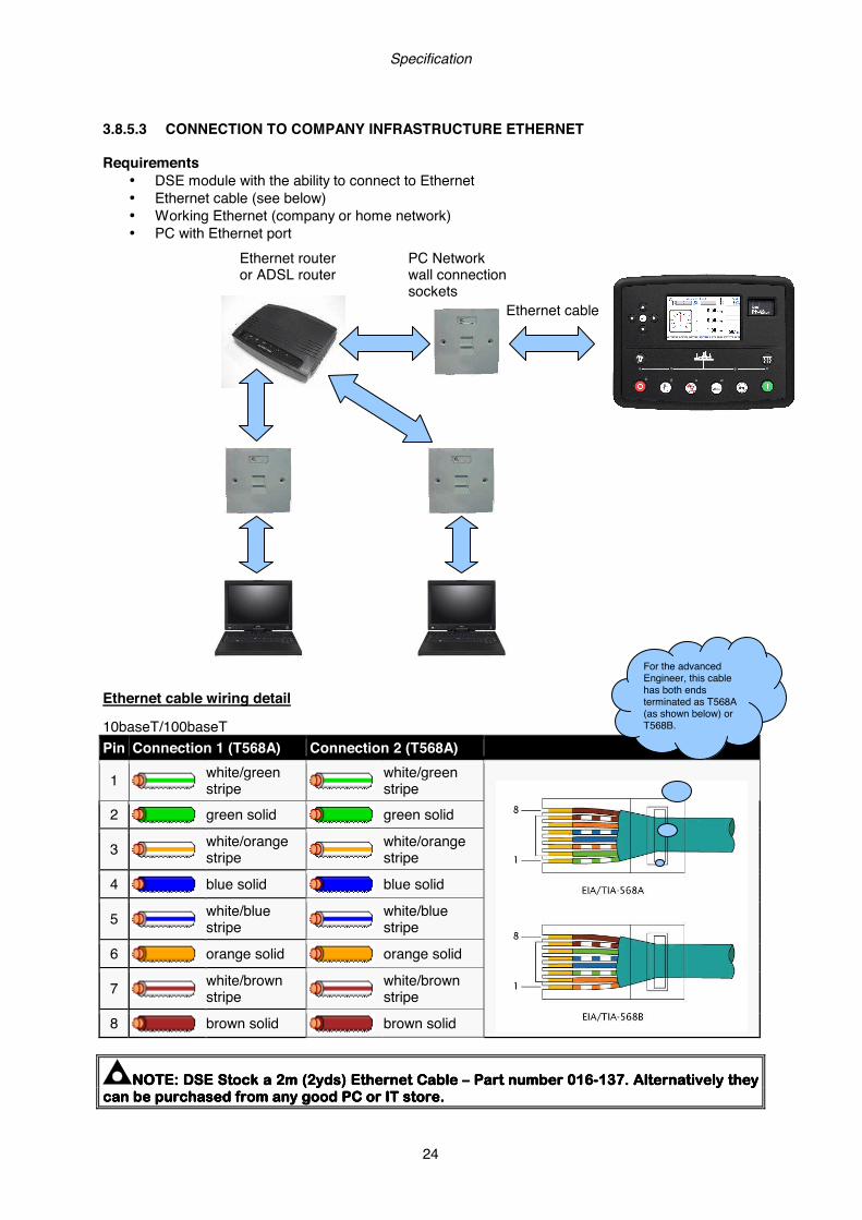
3.8.5.3 CONNECTION TO COMPANY INFRASTRUCTURE ETHERNET Requirements
• DSE module with the ability to connect to Ethernet • Ethernet cable (see below) • Working Ethernet (company or home network) • PC with Ethernet port
Ethernet cable wiring detail 10baseT/100baseT Pin Connection 1 (T568A) Connection 2 (T568A)
1
white/green stripe
white/green stripe
2
green solid
green solid
3
white/orange stripe
white/orange stripe
4
blue solid
blue solid
5
white/blue stripe
white/blue stripe
6
orange solid
orange solid
7
white/brown stripe
white/brown stripe
8
brown solid
brown solid
NOTE:NOTE:NOTE:NOTE: DSE Stock a 2m (2yds) Ethernet Cable DSE Stock a 2m (2yds) Ethernet Cable DSE Stock a 2m (2yds) Ethernet Cable DSE Stock a 2m (2yds) Ethernet Cable –––– Part number 016Part number 016Part number 016Part number 016----137. Alternatively they 137. Alternatively they 137. Alternatively they 137. Alternatively they can be purchased from any good PC or IT store.can be purchased from any good PC or IT store.can be purchased from any good PC or IT store.can be purchased from any good PC or IT store.
Ethernet cable
PC Network wall connection sockets
Ethernet router or ADSL router
For the advanced Engineer, this cable has both ends terminated as T568A (as shown below) or T568B.
Specification
25
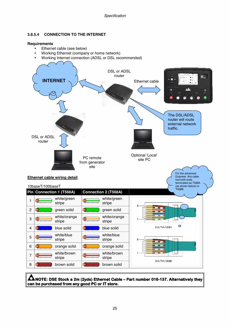
3.8.5.4 CONNECTION TO THE INTERNET Requirements
• Ethernet cable (see below) • Working Ethernet (company or home network) • Working Internet connection (ADSL or DSL recommended)
Ethernet cable wiring detail 10baseT/100baseT Pin Connection 1 (T568A) Connection 2 (T568A)
1
white/green stripe
white/green stripe
2
green solid
green solid
3
white/orange stripe
white/orange stripe
4
blue solid
blue solid
5
white/blue stripe
white/blue stripe
6
orange solid
orange solid
7
white/brown stripe
white/brown stripe
8
brown solid
brown solid
NOTE:NOTE:NOTE:NOTE: DSE Stock a 2m (2yds) Ethernet Cable DSE Stock a 2m (2yds) Ethernet Cable DSE Stock a 2m (2yds) Ethernet Cable DSE Stock a 2m (2yds) Ethernet Cable –––– Part number 016Part number 016Part number 016Part number 016----137. Alternatively they 137. Alternatively they 137. Alternatively they 137. Alternatively they can be purchased from any good PC or IT store.can be purchased from any good PC or IT store.can be purchased from any good PC or IT store.can be purchased from any good PC or IT store.
DSL or ADSL router
Optional ‘Local’ site PC
INTERNET
DSL or ADSL router
PC remote from generator
site
The DSL/ADSL router will route external network traffic.
For the advanced Engineer, this cable has both ends terminated as T568A (as shown below) or T568B.
Ethernet cable

Specification
26
3.8.5.5 FIREWALL CONFIGURATION FOR INTERNET ACCESS As modem/routers differ enormously in their configuration, it is not possible for DSE to give a complete guide to their use with the module. However it is possible to give a description of the requirements in generic terms. For details of how to achieve the connection to your modem/router you are referred to the supplier of your modem/router equipment. The module makes its data available over Modbus TCP and as such communicates over the Ethernet using a Port configured via the DSE Configuration Suite software. You must configure your modem/router to allow inbound traffic on this port. For more information you are referred to your WAN interface device (modem/router) manufacturer. It is also important to note that if the port assigned (setting from software “Modbus Port Number”) is already in use on the LAN, the module cannot be used and another port must be used. Outgoing Firewall rule As the module makes its user interface available to standard web browsers, all communication uses the chosen port. It is usual for a firewall to make the same port outgoing open for communication. Incoming traffic (virtual server) Network Address and Port Translation (NAPT) allows a single device, such as the modem/router gateway, to act as an agent between the Internet (or "public external network") and a local (or "internal private") network. This means that only a single, unique IP address is required to represent an entire group of computers. For our application, this means that the WAN IP address of the modem/router is the IP address we need to access the site from an external (internet) location. When the requests reach the modem/router, we want this passed to a ‘virtual server’ for handling, in our case this is the module. Result : Traffic arriving from the WAN (internet) on port xxx is automatically sent to IP address set within the configuration software on the LAN for handling.
NOTE:NOTE:NOTE:NOTE: Refer to DSE8860 PC Software Configuration Manual (DSE part 057Refer to DSE8860 PC Software Configuration Manual (DSE part 057Refer to DSE8860 PC Software Configuration Manual (DSE part 057Refer to DSE8860 PC Software Configuration Manual (DSE part 057----174)174)174)174) for for for for further details on configuring, monitoring and further details on configuring, monitoring and further details on configuring, monitoring and further details on configuring, monitoring and control.control.control.control.
Specification
27
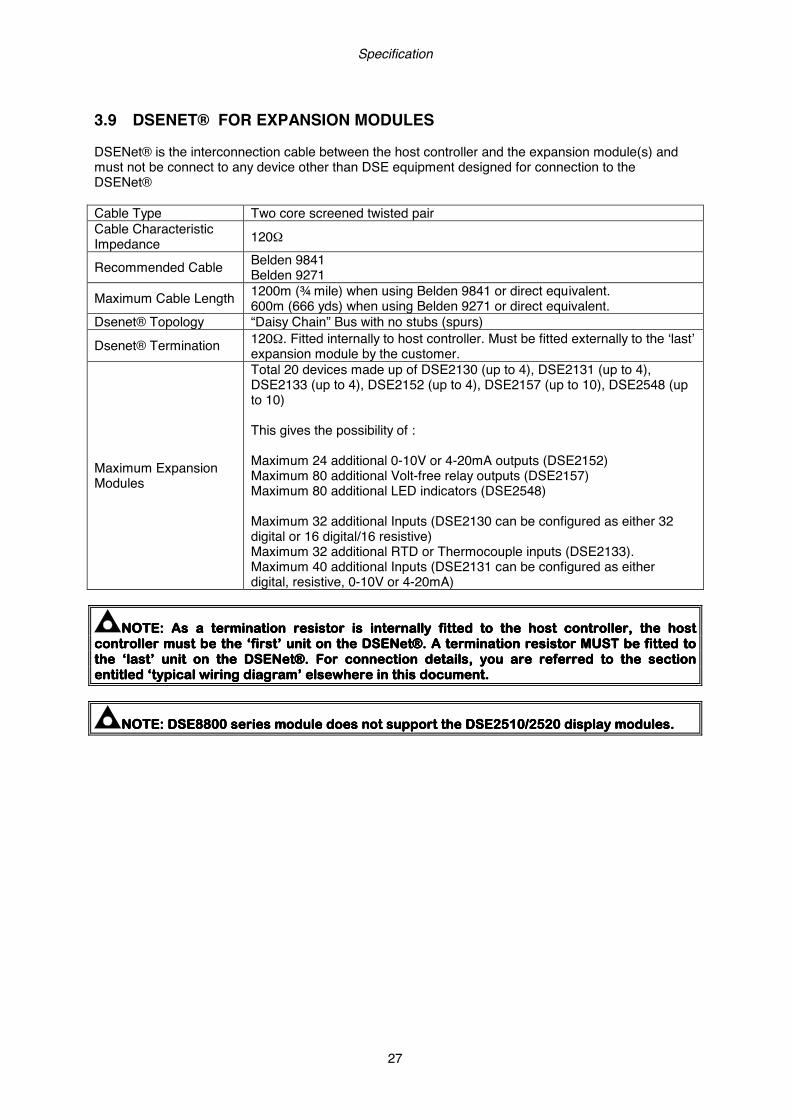
3.9 DSENET® FOR EXPANSION MODULES DSENet® is the interconnection cable between the host controller and the expansion module(s) and must not be connect to any device other than DSE equipment designed for connection to the DSENet® Cable Type Two core screened twisted pair Cable Characteristic Impedance 120Ω
Recommended Cable Belden 9841 Belden 9271
Maximum Cable Length 1200m (¾ mile) when using Belden 9841 or direct equivalent. 600m (666 yds) when using Belden 9271 or direct equivalent.
Dsenet® Topology “Daisy Chain” Bus with no stubs (spurs)
Dsenet® Termination 120Ω. Fitted internally to host controller. Must be fitted externally to the ‘last’ expansion module by the customer.
Maximum Expansion Modules
Total 20 devices made up of DSE2130 (up to 4), DSE2131 (up to 4), DSE2133 (up to 4), DSE2152 (up to 4), DSE2157 (up to 10), DSE2548 (up to 10) This gives the possibility of : Maximum 24 additional 0-10V or 4-20mA outputs (DSE2152) Maximum 80 additional Volt-free relay outputs (DSE2157) Maximum 80 additional LED indicators (DSE2548) Maximum 32 additional Inputs (DSE2130 can be configured as either 32 digital or 16 digital/16 resistive) Maximum 32 additional RTD or Thermocouple inputs (DSE2133). Maximum 40 additional Inputs (DSE2131 can be configured as either digital, resistive, 0-10V or 4-20mA)
NOTE: As a termination resistor is internally fitted to the host controller, the host NOTE: As a termination resistor is internally fitted to the host controller, the host NOTE: As a termination resistor is internally fitted to the host controller, the host NOTE: As a termination resistor is internally fitted to the host controller, the host controller must be the ‘first’ unit on the DSENet®. A termination resistor MUST be fitted to controller must be the ‘first’ unit on the DSENet®. A termination resistor MUST be fitted to controller must be the ‘first’ unit on the DSENet®. A termination resistor MUST be fitted to controller must be the ‘first’ unit on the DSENet®. A termination resistor MUST be fitted to the ‘last’ unit on tthe ‘last’ unit on tthe ‘last’ unit on tthe ‘last’ unit on the DSENet®. For connection details, you are referred to the section he DSENet®. For connection details, you are referred to the section he DSENet®. For connection details, you are referred to the section he DSENet®. For connection details, you are referred to the section entitled ‘typical wiring diagram’ elsewhere in this document.entitled ‘typical wiring diagram’ elsewhere in this document.entitled ‘typical wiring diagram’ elsewhere in this document.entitled ‘typical wiring diagram’ elsewhere in this document.
NOTENOTENOTENOTE: : : : DSEDSEDSEDSE8800880088008800 series module series module series module series module does not support the does not support the does not support the does not support the DSEDSEDSEDSE2510/2520 display modules.2510/2520 display modules.2510/2520 display modules.2510/2520 display modules.
Specification
28
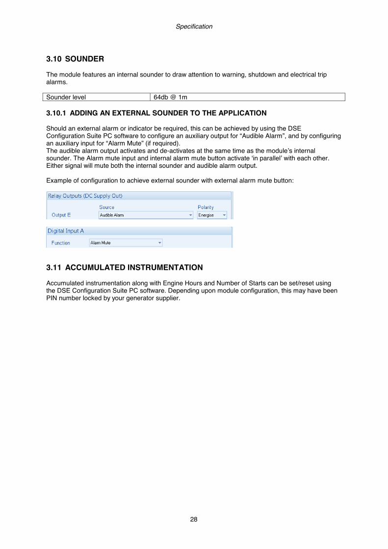
3.10 SOUNDER The module features an internal sounder to draw attention to warning, shutdown and electrical trip alarms. Sounder level 64db @ 1m 3.10.1 ADDING AN EXTERNAL SOUNDER TO THE APPLICATION Should an external alarm or indicator be required, this can be achieved by using the DSE Configuration Suite PC software to configure an auxiliary output for “Audible Alarm”, and by configuring an auxiliary input for “Alarm Mute” (if required). The audible alarm output activates and de-activates at the same time as the module’s internal sounder. The Alarm mute input and internal alarm mute button activate ‘in parallel’ with each other. Either signal will mute both the internal sounder and audible alarm output. Example of configuration to achieve external sounder with external alarm mute button:
3.11 ACCUMULATED INSTRUMENTATION Accumulated instrumentation along with Engine Hours and Number of Starts can be set/reset using the DSE Configuration Suite PC software. Depending upon module configuration, this may have been PIN number locked by your generator supplier.

Specification
29
3.12 DIMENSIONS AND MOUNTING 3.12.1 DIMENSIONS 245 mm x 184 mm x 50 mm (9.6” x 7.2” x 2.0”) 3.12.2 PANEL CUTOUT 220mm x 160mm (8.7” x 6.3”) 3.12.3 WEIGHT 0.7kg (1.4lb) 3.12.4 FIXING CLIPS The module is held into the panel fascia using the supplied fixing clips.
• Withdraw the fixing clip screw (turn anticlockwise) until only the pointed end is protruding from the clip.
• Insert the three ‘prongs’ of the fixing clip into the slots in the side of the module case. • Pull the fixing clip backwards (towards the back of the module) ensuring all three prongs of the
clip are inside their allotted slots. • Turn the fixing clip screws clockwise until they make contact with the panel fascia. • Turn the screws a little more to secure the module into the panel fascia. Care should be taken
not to over tighten the fixing clip screws.
NOTE:NOTE:NOTE:NOTE: In conditions of excessive vibration, mount the module on suitable antiIn conditions of excessive vibration, mount the module on suitable antiIn conditions of excessive vibration, mount the module on suitable antiIn conditions of excessive vibration, mount the module on suitable anti----vvvvibration ibration ibration ibration mountings.mountings.mountings.mountings.
Fixing clip fitted to module
Fixing clip

Specification
30
3.12.5 CABLE TIE FIXING POINTS Integral cable tie fixing points are included on the rear of the module’s case to aid wiring. This additionally provides strain relief to the cable loom by removing the weight of the loom from the screw connectors, thus reducing the chance of future connection failures. Care should be taken not to over tighten the cable tie (for instance with cable tie tools) to prevent the risk of damage to the module case.
Cable tie fixing point With cable and tie in place
3.12.6 SILICON SEALING GASKET The supplied silicon gasket provides improved sealing between module and the panel fascia. The gasket is fitted to the module before installation into the panel fascia. Take care to ensure the gasket is correctly fitted to the module to maintain the integrity of the seal.
Gasket fitted to module
Sealing gasket

Specification
31
3.13 APPLICABLE STANDARDS 3.13.1 BS, UL AND IEEE CLASSIFICATIONS BS 4884-1 This document conforms to BS4884-1 1992 Specification for presentation
of essential information. BS 4884-2 This document conforms to BS4884-2 1993 Guide to content BS 4884-3 This document conforms to BS4884-3 1993 Guide to presentation BS EN 60068-2-1 (Minimum temperature) -30°C (-22°F)
BS EN 60068-2-2 (Maximum temperature)
+70°C (158°F)
BS EN 60950 Safety of information technology equipment, including electrical business equipment
BS EN 61000-6-2 EMC Generic Immunity Standard (Industrial) BS EN 61000-6-4 EMC Generic Emission Standard (Industrial)
BS EN 60529 (Degrees of protection provided by enclosures)
IP65 (front of module when installed into the control panel with the supplied sealing gasket) IP42 (front of module when installed into the control panel WITHOUT being sealed to the panel)
UL508 NEMA rating (Approximate)
12 (Front of module when installed into the control panel with the supplied sealing gasket). 2 (Front of module when installed into the control panel WITHOUT being sealed to the panel)
IEEE C37.2 (Standard Electrical Power System Device Function Numbers and Contact Designations)
Under the scope of IEEE 37.2, function numbers can also be used to represent functions in microprocessor devices and software programs. The controller is device number 11L-8000 (Multifunction device protecting Line (generator) –module). As the module is configurable by the generator OEM, the functions covered by the module will vary. Under the module’s factory configuration, the device numbers included within the module are : 2 – Time Delay Starting Or Closing Relay 3 – Checking Or Interlocking Relay 5 – Stopping Device 6 – Starting Circuit Breaker 8 – Control Power Disconnecting Device 10 – Unit Sequence Switch 11 – Multifunction Device 12 – Overspeed Device 14 – Underspeed Device 15 – Speed Or Frequency Matching Device. 23 – Temperature Control Device 25 – Synchronising Or Synchronism Check Relay 26 – Apparatus Thermal Device 27AC – AC Undervoltage Relay 27DC – DC Undervoltage Relay 29 – Isolating Contactor Or Switch 30 – Annunciator Relay 31 – Separate Excitation Device 37 – Undercurrent Or Underpower Relay (USING INTERNAL PLC EDITOR) 41 – Field Circuit Breaker 42 – Running Circuit Breaker 44 – Unit Sequence Relay
Continued overleaf.

Specification
32
IEEE C37.2 (Standard Electrical Power System Device Function Numbers and Contact Designations)
Continued… 46 – Reverse-Phase Or Phase-Balance Current Relay 48 – Incomplete Sequence Relay 49 – Machine Or Transformer Thermal Relay 50 – Instantaneous overcurrent relay 51 – AC time overcurrent relay 52 – AC circuit breaker 53 – Exciter or DC generator relay 54 – Turning gear engaging device 55 – Power factor relay (USING INTERNAL PLC EDITOR) 59AC – AC overvoltage relay 59DC – DC overvoltage relay 62 – Time delay stopping or opening relay 63 – Pressure switch 71 – Level switch 74 – Alarm relay 77 – Telemetering Device 78 – Phase-angle measuring relay 79 – Reclosing relay (USING INTERNAL PLC EDITOR) 81 – Frequency relay 83 – Automatic selective control or transfer relay 86 – Lockout relay
In line with our policy of continual development, Deep Sea Electronics, reserve the right to change specification without notice.

Specification
33
3.13.2 ENCLOSURE CLASSIFICATIONS
IP CLASSIFICATIONS The modules specification under BS EN 60529 Degrees of protection provided by enclosures IP65 (Front of module when module is installed into the control panel with the optional sealing gasket). IP42 (front of module when module is installed into the control panel WITHOUT being sealed to the panel)
First Digit Second Digit
Protection against contact and ingress of solid objects Protection against ingress of water
0 No protection 0 No protection
1 Protected against ingress solid objects with a diameter of more than 50 mm. No protection against deliberate access, e.g. with a hand, but large surfaces of the body are prevented from approach.
1 Protection against dripping water falling vertically. No harmful effect must be produced (vertically falling drops).
2 Protected against penetration by solid objects with a diameter of more than 12 mm. Fingers or similar objects prevented from approach.
2 Protection against dripping water falling vertically. There must be no harmful effect when the equipment (enclosure) is tilted at an angle up to 15° from its normal pos ition (drops falling at an angle).
3 Protected against ingress of solid objects with a diameter of more than 2.5 mm. Tools, wires etc. with a thickness of more than 2.5 mm are prevented from approach.
3 Protection against water falling at any angle up to 60° from the vertical. There must be no harmful effect (spray water).
4 Protected against ingress of solid objects with a diameter of more than 1 mm. Tools, wires etc. with a thickness of more than 1 mm are prevented from approach.
4 Protection against water splashed against the equipment (enclosure) from any direction. There must be no harmful effect (splashing water).
5 Protected against harmful dust deposits. Ingress of dust is not totally prevented but the dust must not enter in sufficient quantity to interface with satisfactory operation of the equipment. Complete protection against contact.
5 Protection against water projected from a nozzle against the equipment (enclosure) from any direction. There must be no harmful effect (water jet).
6 Protection against ingress of dust (dust tight). Complete protection against contact.
6 Protection against heavy seas or powerful water jets. Water must not enter the equipment (enclosure) in harmful quantities (splashing over).

Specification
34
3.13.3 NEMA CLASSIFICATIONS The modules NEMA Rating (Approximate) 12 (Front of module when module is installed into the control panel with the optional sealing gasket). 2 (front of module when module is installed into the control panel WITHOUT being sealed to the panel)
NOTE: NOTE: NOTE: NOTE: There is no direct equivalence between IP / NEMA ratings. IP figures shown are There is no direct equivalence between IP / NEMA ratings. IP figures shown are There is no direct equivalence between IP / NEMA ratings. IP figures shown are There is no direct equivalence between IP / NEMA ratings. IP figures shown are approximate only.approximate only.approximate only.approximate only.
1
IP30
Provides a degree of protection against contact with the enclosure equipment and against a limited amount of falling dirt.
2
IP31
Provides a degree of protection against limited amounts of falling water and dirt.
3
IP64
Provides a degree of protection against windblown dust, rain and sleet; undamaged by the formation of ice on the enclosure.
3R
IP32
Provides a degree of protection against rain and sleet:; undamaged by the formation of ice on the enclosure.
4 (X)
IP66
Provides a degree of protection against splashing water, windblown dust and rain, hose directed water; undamaged by the formation of ice on the enclosure. (Resist corrosion).
12/12K
IP65
Provides a degree of protection against dust, falling dirt and dripping non corrosive liquids.
13
IP65
Provides a degree of protection against dust and spraying of water, oil and non corrosive coolants.

Installation
35
4 INSTALLATION The module is designed to be mounted on the panel fascia. For dimension and mounting details, see the section entitled Specification, Dimension and mounting elsewhere in this document. 4.1 USER CONNECTIONS To aid user connection, icons are used on the rear of the module to help identify terminal functions. An example of this is shown below.
NOTENOTENOTENOTE: Availability of some terminals depends upon module version. Full details are : Availability of some terminals depends upon module version. Full details are : Availability of some terminals depends upon module version. Full details are : Availability of some terminals depends upon module version. Full details are given in the section engiven in the section engiven in the section engiven in the section entitled Terminal Description elsewhere in this manual.titled Terminal Description elsewhere in this manual.titled Terminal Description elsewhere in this manual.titled Terminal Description elsewhere in this manual.
Terminals 1-15 Terminals 16-20 Terminals 22-38
Terminals 39-46 Terminals 47-50 Terminals 51-57 Terminals 59-70
USB PC Configuration
USB Host Data Logging
Serial ports
Ethernet
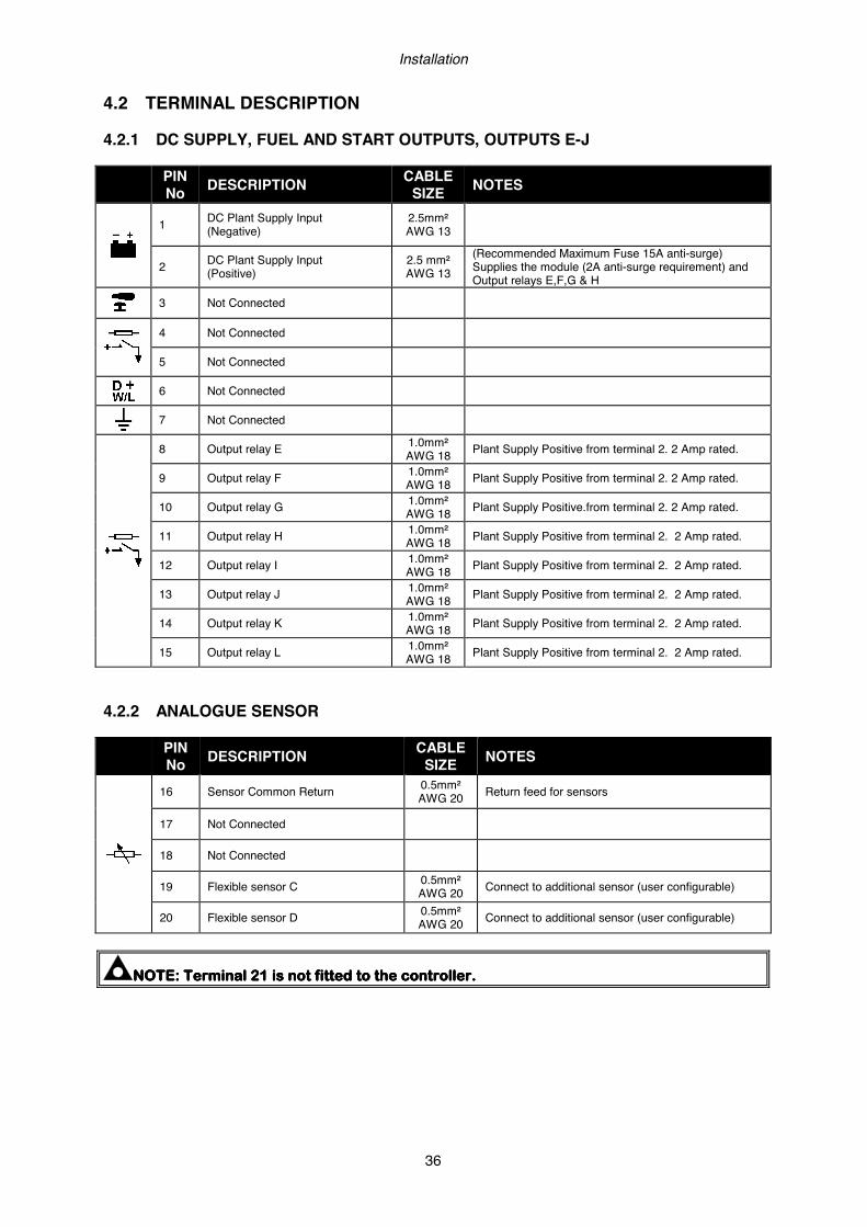
Installation
36
4.2 TERMINAL DESCRIPTION 4.2.1 DC SUPPLY, FUEL AND START OUTPUTS, OUTPUTS E-J
PIN No DESCRIPTION CABLE
SIZE NOTES
1 DC Plant Supply Input (Negative)
2.5mm² AWG 13
2 DC Plant Supply Input (Positive)
2.5 mm² AWG 13
(Recommended Maximum Fuse 15A anti-surge) Supplies the module (2A anti-surge requirement) and Output relays E,F,G & H
3 Not Connected
4 Not Connected
5 Not Connected
6 Not Connected
7 Not Connected
8 Output relay E 1.0mm² AWG 18 Plant Supply Positive from terminal 2. 2 Amp rated.
9 Output relay F 1.0mm² AWG 18 Plant Supply Positive from terminal 2. 2 Amp rated.
10 Output relay G 1.0mm² AWG 18 Plant Supply Positive.from terminal 2. 2 Amp rated.
11 Output relay H 1.0mm² AWG 18 Plant Supply Positive from terminal 2. 2 Amp rated.
12 Output relay I 1.0mm² AWG 18 Plant Supply Positive from terminal 2. 2 Amp rated.
13 Output relay J 1.0mm² AWG 18 Plant Supply Positive from terminal 2. 2 Amp rated.
14 Output relay K 1.0mm² AWG 18 Plant Supply Positive from terminal 2. 2 Amp rated.
15 Output relay L 1.0mm² AWG 18 Plant Supply Positive from terminal 2. 2 Amp rated.
4.2.2 ANALOGUE SENSOR
PIN No DESCRIPTION CABLE
SIZE NOTES
16 Sensor Common Return 0.5mm² AWG 20 Return feed for sensors
17 Not Connected
18 Not Connected
19 Flexible sensor C 0.5mm² AWG 20 Connect to additional sensor (user configurable)
20 Flexible sensor D 0.5mm² AWG 20 Connect to additional sensor (user configurable)
NOTE:NOTE:NOTE:NOTE: TerminaTerminaTerminaTerminallll 21 21 21 21 isisisis not fitted to the controller.not fitted to the controller.not fitted to the controller.not fitted to the controller.
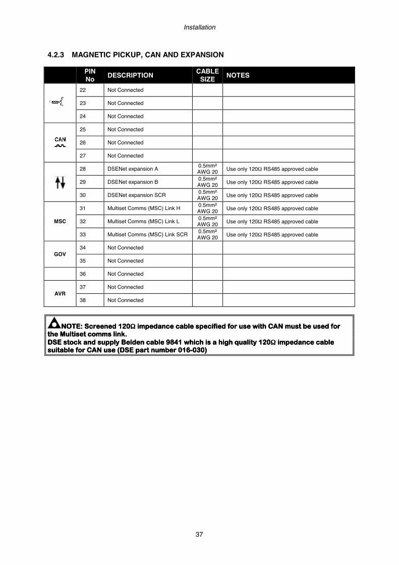
Installation
37
4.2.3 MAGNETIC PICKUP, CAN AND EXPANSION
PIN No DESCRIPTION CABLE
SIZE NOTES
22 Not Connected
23 Not Connected
24 Not Connected
25 Not Connected
26 Not Connected
27 Not Connected
28 DSENet expansion A 0.5mm²
AWG 20 Use only 120Ω RS485 approved cable
29 DSENet expansion B 0.5mm² AWG 20 Use only 120Ω RS485 approved cable
30 DSENet expansion SCR 0.5mm² AWG 20 Use only 120Ω RS485 approved cable
MSC
31 Multiset Comms (MSC) Link H 0.5mm² AWG 20 Use only 120Ω RS485 approved cable
32 Multiset Comms (MSC) Link L 0.5mm² AWG 20 Use only 120Ω RS485 approved cable
33 Multiset Comms (MSC) Link SCR 0.5mm² AWG 20 Use only 120Ω RS485 approved cable
GOV 34 Not Connected
35 Not Connected
36 Not Connected
AVR 37 Not Connected
38 Not Connected
NOTE:NOTE:NOTE:NOTE: Screened 120Screened 120Screened 120Screened 120ΩΩΩΩ impedance cable specified for usimpedance cable specified for usimpedance cable specified for usimpedance cable specified for use with CAN must be used for e with CAN must be used for e with CAN must be used for e with CAN must be used for the the the the Multiset comms link.Multiset comms link.Multiset comms link.Multiset comms link. DSE stock and supply Belden cable 98DSE stock and supply Belden cable 98DSE stock and supply Belden cable 98DSE stock and supply Belden cable 9841 which is a high quality 12041 which is a high quality 12041 which is a high quality 12041 which is a high quality 120ΩΩΩΩ impedance cable impedance cable impedance cable impedance cable suitable for CAN use (DSE part number 016suitable for CAN use (DSE part number 016suitable for CAN use (DSE part number 016suitable for CAN use (DSE part number 016----030)030)030)030)

Installation
38
4.2.4 LOAD SWITCHING AND V1 MAINS VOLTAGE SENSING
PIN No DESCRIPTION CABLE
SIZE NOTES
39 Output relay C 1.0mm
AWG 18 Normally configured to control mains contactor coil (Recommend 10A fuse)
40 Output relay C 1.0mm AWG 18 Normally configured to control mains contactor coil
41 Output relay D 1.0mm
AWG 18 Normally configured to control generator contactor coil (Recommend 10A fuse)
42 Output relay D 1.0mm AWG 18 Normally configured to control generator contactor coil
V1
43 Mains L1 (R) voltage monitoring
1.0mm AWG 18
Connect to Mains L1 (R) incoming supply (AC) (Recommend 2A fuse)
44 Mains L2 (S) voltage monitoring
1.0mm AWG 18
Connect to Mains L1 (S) incoming supply (AC) (Recommend 2A fuse)
45 Mains L3 (T) voltage monitoring
1.0mm AWG 18
Connect to Mains L1 (T) incoming supply (AC) (Recommend 2A fuse)
46 Mains Neutral (N) input 1.0mm AWG 18
Connect to Mains N incoming supply (AC)
NOTE:NOTE:NOTE:NOTE: The above taThe above taThe above taThe above table describes connections to a three phase, four wire alternator. ble describes connections to a three phase, four wire alternator. ble describes connections to a three phase, four wire alternator. ble describes connections to a three phase, four wire alternator. For alternative wiring topologies, please see the ALTERNATIVE AC TOPOLOGIES section of For alternative wiring topologies, please see the ALTERNATIVE AC TOPOLOGIES section of For alternative wiring topologies, please see the ALTERNATIVE AC TOPOLOGIES section of For alternative wiring topologies, please see the ALTERNATIVE AC TOPOLOGIES section of this manual.this manual.this manual.this manual.
4.2.5 V2 BUS VOLTAGE SENSING
PIN No DESCRIPTION CABLE
SIZE NOTES
V2
47 Bus L1 (R) voltage monitoring 1.0mm AWG 18
Connect to Bus L1 (U) output (AC) (Recommend 2A fuse)
48 Bus L2 (S) voltage monitoring 1.0mm AWG 18
Connect to Bus L2 (V) output (AC) (Recommend 2A fuse)
49 Bus L3 (T) voltage monitoring 1.0mm AWG 18
Connect to Bus L3 (W) output (AC) (Recommend 2A fuse)
50 Bus Neutral (N) input 1.0mm AWG 18 Connect to Bus Neutral terminal (AC)
NOTE:NOTE:NOTE:NOTE: The above table describes connections to a three phase, four wire alternator. The above table describes connections to a three phase, four wire alternator. The above table describes connections to a three phase, four wire alternator. The above table describes connections to a three phase, four wire alternator. For alternative wiring topologies, please see the ALTERNATIVE AC TOFor alternative wiring topologies, please see the ALTERNATIVE AC TOFor alternative wiring topologies, please see the ALTERNATIVE AC TOFor alternative wiring topologies, please see the ALTERNATIVE AC TOPOLOGIES section of POLOGIES section of POLOGIES section of POLOGIES section of this manual.this manual.this manual.this manual.

Installation
39
4.2.6 MAINS CURRENT TRANSFORMERS
WARNINGWARNINGWARNINGWARNING!!!!:::: Do not disconnect this plug when the CTs are carrying current. Do not disconnect this plug when the CTs are carrying current. Do not disconnect this plug when the CTs are carrying current. Do not disconnect this plug when the CTs are carrying current. Disconnection will open circuit the secondary of the C.T.’s and dangerous voltages may Disconnection will open circuit the secondary of the C.T.’s and dangerous voltages may Disconnection will open circuit the secondary of the C.T.’s and dangerous voltages may Disconnection will open circuit the secondary of the C.T.’s and dangerous voltages may then develop. Always ensure thethen develop. Always ensure thethen develop. Always ensure thethen develop. Always ensure the CTs are not carrying current and the CTs are short circuit CTs are not carrying current and the CTs are short circuit CTs are not carrying current and the CTs are short circuit CTs are not carrying current and the CTs are short circuit connected before making or breaking connections to the module.connected before making or breaking connections to the module.connected before making or breaking connections to the module.connected before making or breaking connections to the module.
NOTE:NOTE:NOTE:NOTE: The module has a burden of 0.5VA on the CT. Ensure the CT is rated for the The module has a burden of 0.5VA on the CT. Ensure the CT is rated for the The module has a burden of 0.5VA on the CT. Ensure the CT is rated for the The module has a burden of 0.5VA on the CT. Ensure the CT is rated for the burden of the controller, the cable length being uburden of the controller, the cable length being uburden of the controller, the cable length being uburden of the controller, the cable length being used and any other equipment sharing the sed and any other equipment sharing the sed and any other equipment sharing the sed and any other equipment sharing the CT. If in doubt, consult your CT supplier.CT. If in doubt, consult your CT supplier.CT. If in doubt, consult your CT supplier.CT. If in doubt, consult your CT supplier.
NOTE:NOTE:NOTE:NOTE: Take care to ensure correct polarity of the CT primary as shown below. If in Take care to ensure correct polarity of the CT primary as shown below. If in Take care to ensure correct polarity of the CT primary as shown below. If in Take care to ensure correct polarity of the CT primary as shown below. If in doubt, check with the CT supplier.doubt, check with the CT supplier.doubt, check with the CT supplier.doubt, check with the CT supplier.
CT LABELLING p1, k or K is the primary of the CT that ‘points’ towards the MAINS p2, l or L is the primary of the CT that ‘points’ towards the LOAD s1 is the secondary of the CT that connects to the DSE Module’s input for the CT measuring (I1,I2,I3) s2 is the secondary of the CT that should be commoned with the s2 connections of all the other CTs and connected to the CT common terminal of the module.
TO MAINS
TO LOAD SWITCH DEVICE
POLARITY OF CT PRIMARY
PIN No DESCRIPTION CABLE
SIZE NOTES
51 CT Secondary for Mains L1 2.5mm² AWG 13 Connect to s1 secondary of L1 monitoring CT
52 CT Secondary for Mains L2 2.5mm² AWG 13 Connect to s1 secondary of L2 monitoring CT
53 CT Secondary for Mains L3 2.5mm² AWG 13 Connect to s1 secondary of L3 monitoring CT
54 DO NOT CONNECT
55 Common for CTs connected to L1,L2,L3 (s2)
2.5mm² AWG 13
Connect to s2 secondary of L1,L2,L3 monitoring CTs
NOTE: NOTE: NOTE: NOTE: Take care to ensure correct polarity of the CT primary as shown overleaf. If in Take care to ensure correct polarity of the CT primary as shown overleaf. If in Take care to ensure correct polarity of the CT primary as shown overleaf. If in Take care to ensure correct polarity of the CT primary as shown overleaf. If in doubt, check with the CT supplier.doubt, check with the CT supplier.doubt, check with the CT supplier.doubt, check with the CT supplier.
labelled as p1, k or K
labelled as p2, l or L

Installation
40
4.2.7 BUS/LOAD CURRENT TRANSFORMER
WARNING!: WARNING!: WARNING!: WARNING!: Do not disconnect this plug when the CT is carrying current. Disconnection Do not disconnect this plug when the CT is carrying current. Disconnection Do not disconnect this plug when the CT is carrying current. Disconnection Do not disconnect this plug when the CT is carrying current. Disconnection will open circuit the secondary of the C.T. and dangerous voltages may then develop. will open circuit the secondary of the C.T. and dangerous voltages may then develop. will open circuit the secondary of the C.T. and dangerous voltages may then develop. will open circuit the secondary of the C.T. and dangerous voltages may then develop. Always ensure the CT is not carrying current and the CT is short circuit connected bAlways ensure the CT is not carrying current and the CT is short circuit connected bAlways ensure the CT is not carrying current and the CT is short circuit connected bAlways ensure the CT is not carrying current and the CT is short circuit connected before efore efore efore making or breaking connections to the module.making or breaking connections to the module.making or breaking connections to the module.making or breaking connections to the module.
NOTE:NOTE:NOTE:NOTE: Bus/LoadBus/LoadBus/LoadBus/Load CT is NOT REQUIRED in a system including only one mains supply CT is NOT REQUIRED in a system including only one mains supply CT is NOT REQUIRED in a system including only one mains supply CT is NOT REQUIRED in a system including only one mains supply (with one (with one (with one (with one DSEDSEDSEDSE8888xxxx66660 controller). See section below detailing advantages of the 0 controller). See section below detailing advantages of the 0 controller). See section below detailing advantages of the 0 controller). See section below detailing advantages of the Bus/LoadBus/LoadBus/LoadBus/Load CT CT CT CT in a multiple mains (multiple in a multiple mains (multiple in a multiple mains (multiple in a multiple mains (multiple DSE8xDSE8xDSE8xDSE8x60) system.60) system.60) system.60) system.
NOTE: NOTE: NOTE: NOTE: The module has a burden of 0.5VA on the CT. Ensure the CT is rated for the The module has a burden of 0.5VA on the CT. Ensure the CT is rated for the The module has a burden of 0.5VA on the CT. Ensure the CT is rated for the The module has a burden of 0.5VA on the CT. Ensure the CT is rated for the burden of the controller, the cable length used and any other equipment sharing the CT. If burden of the controller, the cable length used and any other equipment sharing the CT. If burden of the controller, the cable length used and any other equipment sharing the CT. If burden of the controller, the cable length used and any other equipment sharing the CT. If in doubt, consult your CT supplier.in doubt, consult your CT supplier.in doubt, consult your CT supplier.in doubt, consult your CT supplier.
NOTE: NOTE: NOTE: NOTE: Take care to ensure correcTake care to ensure correcTake care to ensure correcTake care to ensure correct polarity of the CT primary as shown below. If in t polarity of the CT primary as shown below. If in t polarity of the CT primary as shown below. If in t polarity of the CT primary as shown below. If in doubt, check with the CT supplier.doubt, check with the CT supplier.doubt, check with the CT supplier.doubt, check with the CT supplier.
Pin No Description CABLE
SIZE NOTES
56 CT Secondary for Bus/Load CT 2.5mm²
AWG 13 Connect to s1 secondary of Bus/Load CT
57 CT Secondary for Bus/Load CT 2.5mm² AWG 13 Connect to s2 secondary of Bus/Load CT
NOTE: NOTE: NOTE: NOTE: Take care to ensure correct polarity of the CT primary as shown in the previous Take care to ensure correct polarity of the CT primary as shown in the previous Take care to ensure correct polarity of the CT primary as shown in the previous Take care to ensure correct polarity of the CT primary as shown in the previous section. If in doubt, check with the CT supplier.section. If in doubt, check with the CT supplier.section. If in doubt, check with the CT supplier.section. If in doubt, check with the CT supplier.
4.2.7.1 ADVANTAGES OF BUS/LOAD CT The Bus/Load CT is only required when there is more than one DSE8x60 on the same system. When the Bus/Load CT is fitted, the DSE8x60 transfers the right amount of load to the mains before disconnecting the bus, preventing the generator(s) from being shock loaded/unloaded. Without the Bus/Load CT, the DSE8x60 does not know how much load to transfer to the mains when other DSE8x60’s are still in island mode. The DSE8x60 would transfer a pre-determined amount of load before disconnecting the bus from the mains. This would lead to there being too much load or not enough load transferred, and the generator(s) would be shock loaded/unloaded as the bus disconnect from the mains.

Installation
41
4.2.8 CONFIGURABLE DIGITAL INPUTS
PIN No DESCRIPTION CABLE
SIZE NOTES
59 Configurable digital input A 0.5mm² AWG 20 Switch to negative
60 Configurable digital input B 0.5mm² AWG 20 Switch to negative
61 Configurable digital input C 0.5mm² AWG 20 Switch to negative
62 Configurable digital input D 0.5mm² AWG 20 Switch to negative
63 Configurable digital input E 0.5mm² AWG 20 Switch to negative
64 Configurable digital input F 0.5mm² AWG 20 Switch to negative
65 Configurable digital input G 0.5mm² AWG 20 Switch to negative
66 Configurable digital input H 0.5mm² AWG 20 Switch to negative
67 Configurable digital input I 0.5mm² AWG 20 Switch to negative
68 Configurable digital input J 0.5mm² AWG 20 Switch to negative
69 Configurable digital input K 0.5mm² AWG 20 Switch to negative
70 Configurable digital input L 0.5mm² AWG 20 Switch to negative
NOTE: NOTE: NOTE: NOTE: See the softwarSee the softwarSee the softwarSee the software manual fore manual fore manual fore manual for fullfullfullfull range of configurable outputs available.range of configurable outputs available.range of configurable outputs available.range of configurable outputs available.
4.2.9 PC CONFIGURATION INTERFACE CONNECTOR
DESCRIPTION CABLE SIZE NOTES
Socket for connection to PC with DSE Configuration Suite Software
0.5mm² AWG 20
This is a standard USB type A to type B connector.
NOTE:NOTE:NOTE:NOTE: The USB connection cable between the PC and the The USB connection cable between the PC and the The USB connection cable between the PC and the The USB connection cable between the PC and the module module module module must not be extended must not be extended must not be extended must not be extended beyond 5m (yards). For distances over 5m, it is possible to use a third party USB extender. beyond 5m (yards). For distances over 5m, it is possible to use a third party USB extender. beyond 5m (yards). For distances over 5m, it is possible to use a third party USB extender. beyond 5m (yards). For distances over 5m, it is possible to use a third party USB extender. Typically, they extend USB up to 50m (Typically, they extend USB up to 50m (Typically, they extend USB up to 50m (Typically, they extend USB up to 50m (yards). The supply and support of this type of yards). The supply and support of this type of yards). The supply and support of this type of yards). The supply and support of this type of equipment is outside the scope of Deep Sea Electronics PLC.equipment is outside the scope of Deep Sea Electronics PLC.equipment is outside the scope of Deep Sea Electronics PLC.equipment is outside the scope of Deep Sea Electronics PLC.
CAUTION!: Care must be taken not to overload the PCs USB system by connecting CAUTION!: Care must be taken not to overload the PCs USB system by connecting CAUTION!: Care must be taken not to overload the PCs USB system by connecting CAUTION!: Care must be taken not to overload the PCs USB system by connecting more than the recommended number of USB devices to the PC. For furthemore than the recommended number of USB devices to the PC. For furthemore than the recommended number of USB devices to the PC. For furthemore than the recommended number of USB devices to the PC. For further information, r information, r information, r information, consult your PC supplier.consult your PC supplier.consult your PC supplier.consult your PC supplier.
CAUTION!: This socket must not be used for any other purpose.CAUTION!: This socket must not be used for any other purpose.CAUTION!: This socket must not be used for any other purpose.CAUTION!: This socket must not be used for any other purpose.
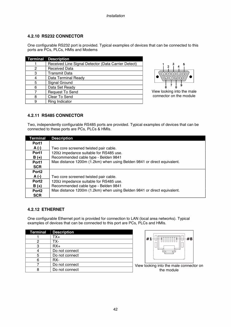
Installation
42
4.2.10 RS232 CONNECTOR One configurable RS232 port is provided. Typical examples of devices that can be connected to this ports are PCs, PLCs, HMIs and Modems Terminal Description
View looking into the male connector on the module
1 Received Line Signal Detector (Data Carrier Detect) 2 Received Data 3 Transmit Data 4 Data Terminal Ready 5 Signal Ground 6 Data Set Ready 7 Request To Send 8 Clear To Send 9 Ring Indicator
4.2.11 RS485 CONNECTOR Two, independently configurable RS485 ports are provided. Typical examples of devices that can be connected to these ports are PCs, PLCs & HMIs. Terminal Description
Port1 A (-) Two core screened twisted pair cable.
120Ω impedance suitable for RS485 use. Recommended cable type - Belden 9841 Max distance 1200m (1.2km) when using Belden 9841 or direct equivalent.
Port1 B (+) Port1 SCR Port2 A (-) Two core screened twisted pair cable.
120Ω impedance suitable for RS485 use. Recommended cable type - Belden 9841 Max distance 1200m (1.2km) when using Belden 9841 or direct equivalent.
Port2 B (+) Port2 SCR
4.2.12 ETHERNET One configurable Ethernet port is provided for connection to LAN (local area networks). Typical examples of devices that can be connected to this port are PCs, PLCs and HMIs.
Terminal Description
View looking into the male connector on
the module
1 TX+ 2 TX- 3 RX+ 4 Do not connect 5 Do not connect 6 RX- 7 Do not connect 8 Do not connect
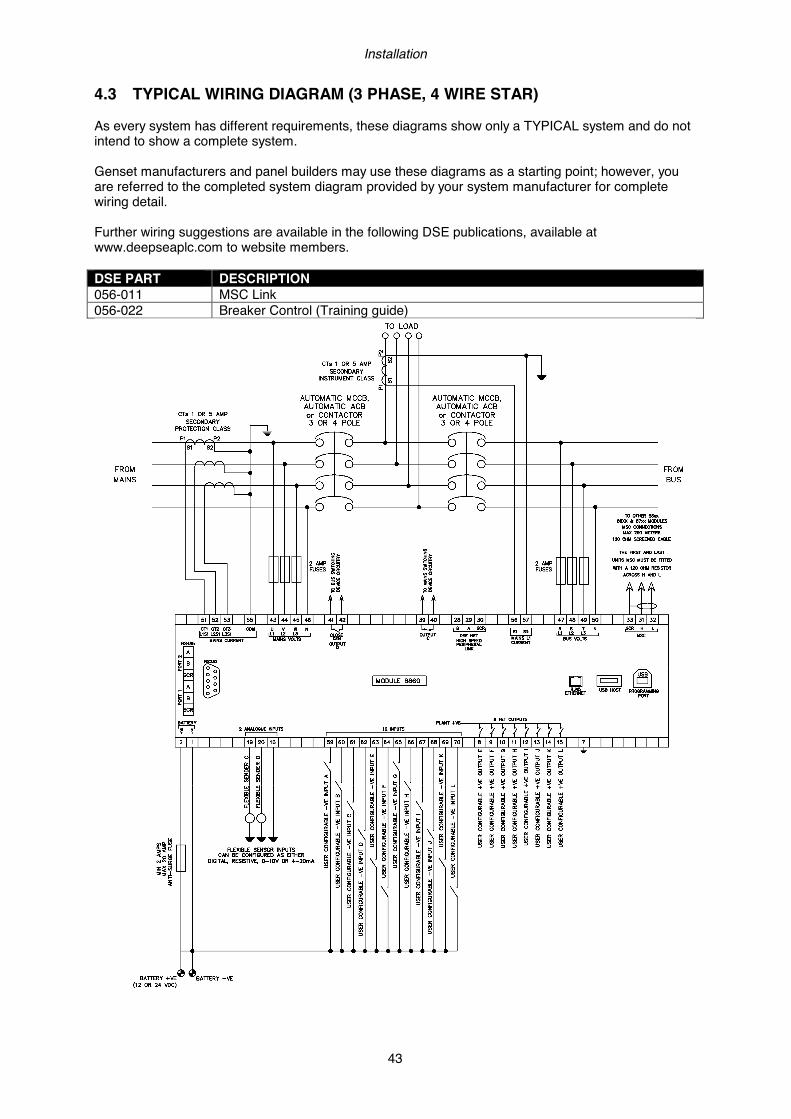
Installation
43
4.3 TYPICAL WIRING DIAGRAM (3 PHASE, 4 WIRE STAR) As every system has different requirements, these diagrams show only a TYPICAL system and do not intend to show a complete system. Genset manufacturers and panel builders may use these diagrams as a starting point; however, you are referred to the completed system diagram provided by your system manufacturer for complete wiring detail. Further wiring suggestions are available in the following DSE publications, available at www.deepseaplc.com to website members. DSE PART DESCRIPTION 056-011 MSC Link 056-022 Breaker Control (Training guide)
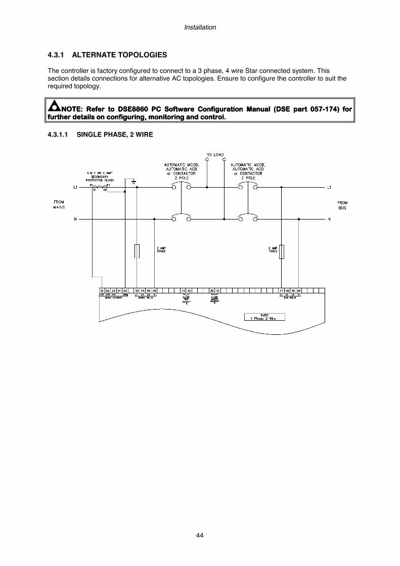
Installation
44
4.3.1 ALTERNATE TOPOLOGIES The controller is factory configured to connect to a 3 phase, 4 wire Star connected system. This section details connections for alternative AC topologies. Ensure to configure the controller to suit the required topology.
NOTE:NOTE:NOTE:NOTE: Refer to DSE8860 PC Software Configuration Manual (DSE part 057Refer to DSE8860 PC Software Configuration Manual (DSE part 057Refer to DSE8860 PC Software Configuration Manual (DSE part 057Refer to DSE8860 PC Software Configuration Manual (DSE part 057----174)174)174)174) for for for for further details on configuring, monitoring and control.further details on configuring, monitoring and control.further details on configuring, monitoring and control.further details on configuring, monitoring and control.
4.3.1.1 SINGLE PHASE, 2 WIRE
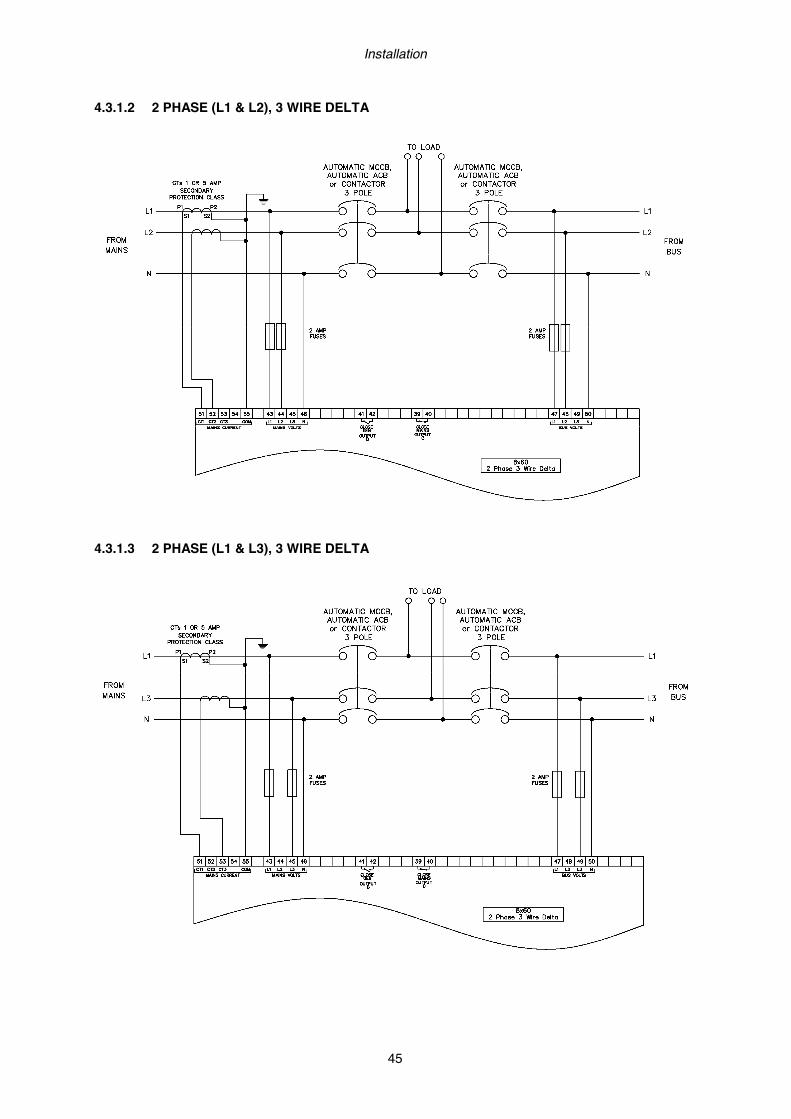
Installation
45
4.3.1.2 2 PHASE (L1 & L2), 3 WIRE DELTA
4.3.1.3 2 PHASE (L1 & L3), 3 WIRE DELTA
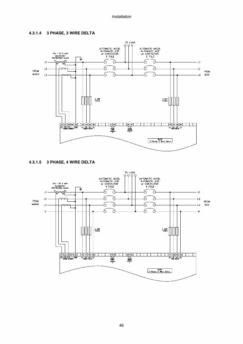
Installation
46
4.3.1.4 3 PHASE, 3 WIRE DELTA
4.3.1.5 3 PHASE, 4 WIRE DELTA
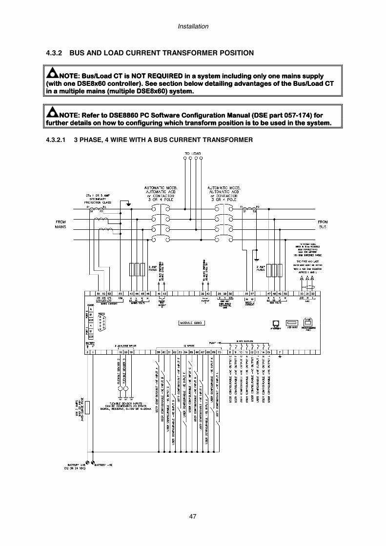
Installation
47
4.3.2 BUS AND LOAD CURRENT TRANSFORMER POSITION
NOTE:NOTE:NOTE:NOTE: Bus/LoadBus/LoadBus/LoadBus/Load CT is NOT REQUIRED in a system including only one mains suppCT is NOT REQUIRED in a system including only one mains suppCT is NOT REQUIRED in a system including only one mains suppCT is NOT REQUIRED in a system including only one mains supply ly ly ly (with one (with one (with one (with one DSE8xDSE8xDSE8xDSE8x60 controller). See section below detailing advantages of the 60 controller). See section below detailing advantages of the 60 controller). See section below detailing advantages of the 60 controller). See section below detailing advantages of the Bus/LoadBus/LoadBus/LoadBus/Load CT CT CT CT in a multiple mains (multiple in a multiple mains (multiple in a multiple mains (multiple in a multiple mains (multiple DSE8xDSE8xDSE8xDSE8x60) system.60) system.60) system.60) system.
NOTE:NOTE:NOTE:NOTE: Refer to DSE8860 Refer to DSE8860 Refer to DSE8860 Refer to DSE8860 PC Software PC Software PC Software PC Software Configuration Manual (DSE part 057Configuration Manual (DSE part 057Configuration Manual (DSE part 057Configuration Manual (DSE part 057----174) for 174) for 174) for 174) for further details on further details on further details on further details on how to how to how to how to configurinconfigurinconfigurinconfiguringggg which transform position is to be used in the system.which transform position is to be used in the system.which transform position is to be used in the system.which transform position is to be used in the system.
4.3.2.1 3 PHASE, 4 WIRE WITH A BUS CURRENT TRANSFORMER

Installation
48
4.3.2.2 3 PHASE, 4 WIRE WITH A LOAD CURRENT TRANSFORMER
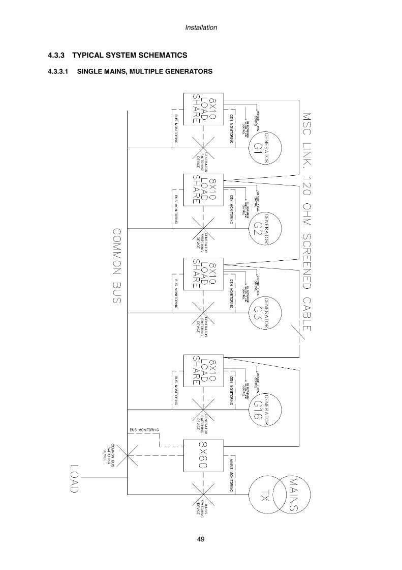
Installation
49
4.3.3 TYPICAL SYSTEM SCHEMATICS 4.3.3.1 SINGLE MAINS, MULTIPLE GENERATORS
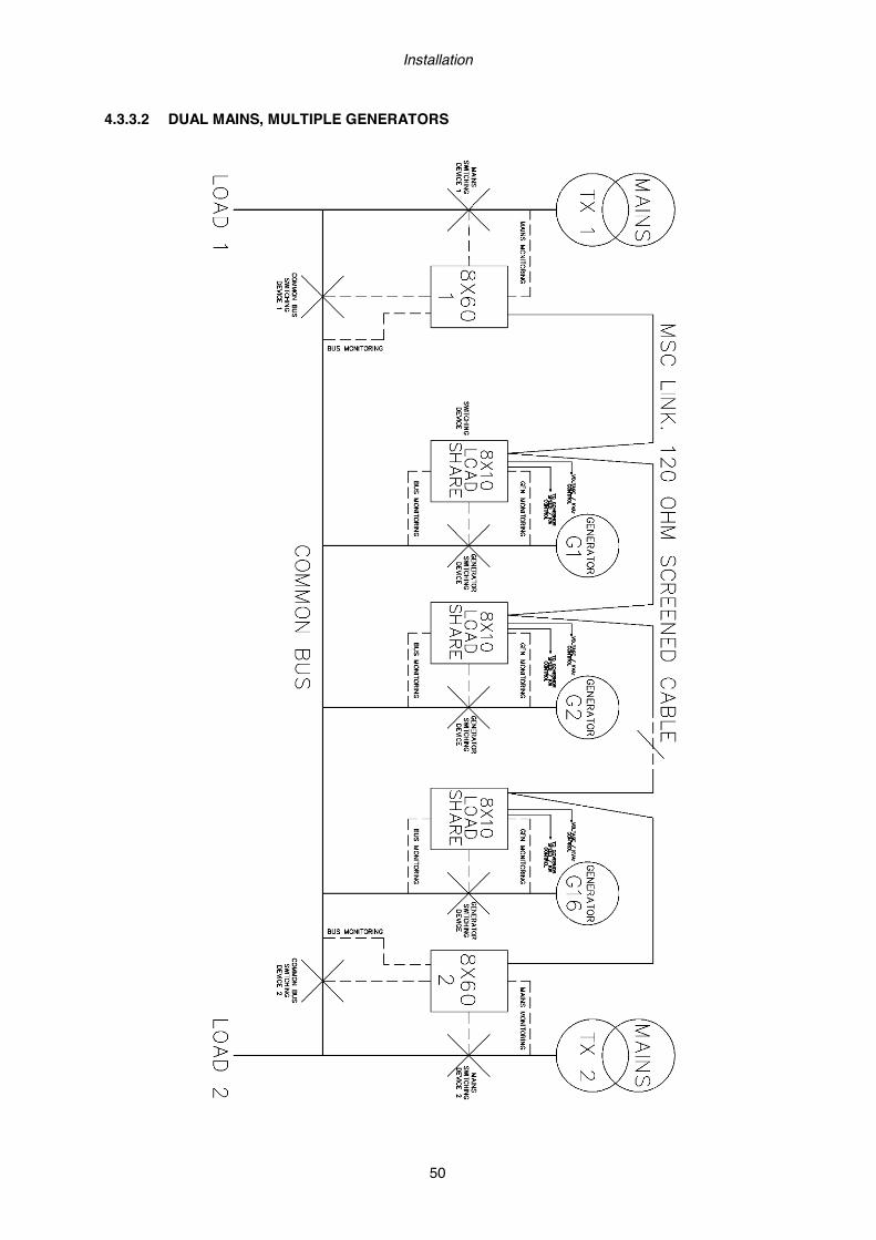
Installation
50
4.3.3.2 DUAL MAINS, MULTIPLE GENERATORS

Installation
51
4.3.3.3 MULTIPLE MAINS, MULTIPLE GENERATORS
Installation
52
4.4 EARTH SYSTEMS 4.4.1 NEGATIVE EARTH The typical wiring diagrams located within this document show connections for a negative earth system (the battery negative connects to Earth) 4.4.2 POSITIVE EARTH When using a DSE module with a Positive Earth System (the battery positive connects to Earth), the following points must be followed:
• Follow the typical wiring diagram as normal for all sections EXCEPT the earth points • All points shown as Earth on the typical wiring diagram should connect to BATTERY
NEGATIVE (not earth). 4.4.3 FLOATING EARTH Where neither the battery positive nor battery negative terminals are connected to earth the following points must to be followed
• Follow the typical wiring diagram as normal for all sections EXCEPT the earth points • All points shown as Earth on the typical wiring diagram should connect to BATTERY
NEGATIVE (not earth).
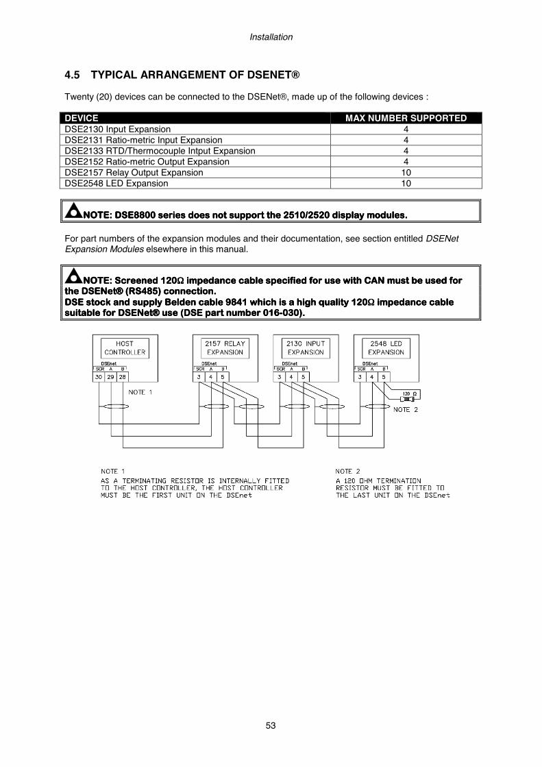
Installation
53
4.5 TYPICAL ARRANGEMENT OF DSENET® Twenty (20) devices can be connected to the DSENet®, made up of the following devices : DEVICE MAX NUMBER SUPPORTED DSE2130 Input Expansion 4 DSE2131 Ratio-metric Input Expansion 4 DSE2133 RTD/Thermocouple Intput Expansion 4 DSE2152 Ratio-metric Output Expansion 4 DSE2157 Relay Output Expansion 10 DSE2548 LED Expansion 10
NOTENOTENOTENOTE: DSE8800 series does not support the 2510/2520 display modules.: DSE8800 series does not support the 2510/2520 display modules.: DSE8800 series does not support the 2510/2520 display modules.: DSE8800 series does not support the 2510/2520 display modules.
For part numbers of the expansion modules and their documentation, see section entitled DSENet Expansion Modules elsewhere in this manual.
NOTE: Screened 120NOTE: Screened 120NOTE: Screened 120NOTE: Screened 120ΩΩΩΩ impedance cable specified forimpedance cable specified forimpedance cable specified forimpedance cable specified for use with CAN must be used for use with CAN must be used for use with CAN must be used for use with CAN must be used for the DSENet® (RS485) connection.the DSENet® (RS485) connection.the DSENet® (RS485) connection.the DSENet® (RS485) connection. DSE stock and supply Belden cable 9841 which is a high quality 120DSE stock and supply Belden cable 9841 which is a high quality 120DSE stock and supply Belden cable 9841 which is a high quality 120DSE stock and supply Belden cable 9841 which is a high quality 120ΩΩΩΩ impedance cable impedance cable impedance cable impedance cable suitable for DSENet® use (DSE part number 016suitable for DSENet® use (DSE part number 016suitable for DSENet® use (DSE part number 016suitable for DSENet® use (DSE part number 016----030)030)030)030)....
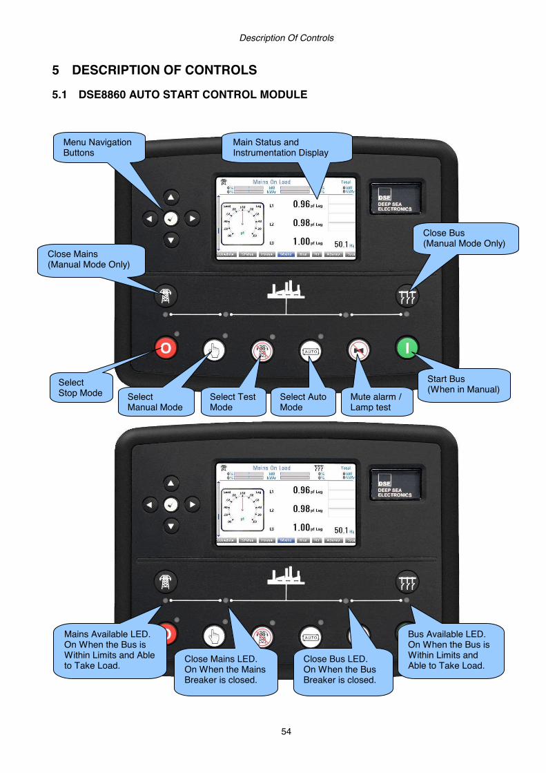
Description Of Controls
54
5 DESCRIPTION OF CONTROLS 5.1 DSE8860 AUTO START CONTROL MODULE
Menu Navigation Buttons
Select Stop Mode Select
Manual Mode Select Auto Mode
Mute alarm / Lamp test
Start Bus (When in Manual)
Close Bus (Manual Mode Only) Close Mains
(Manual Mode Only)
Main Status and Instrumentation Display
Close Bus LED. On When the Bus Breaker is closed.
Bus Available LED. On When the Bus is Within Limits and Able to Take Load.
Mains Available LED. On When the Bus is Within Limits and Able to Take Load.
Close Mains LED. On When the Mains Breaker is closed.
Select Test Mode
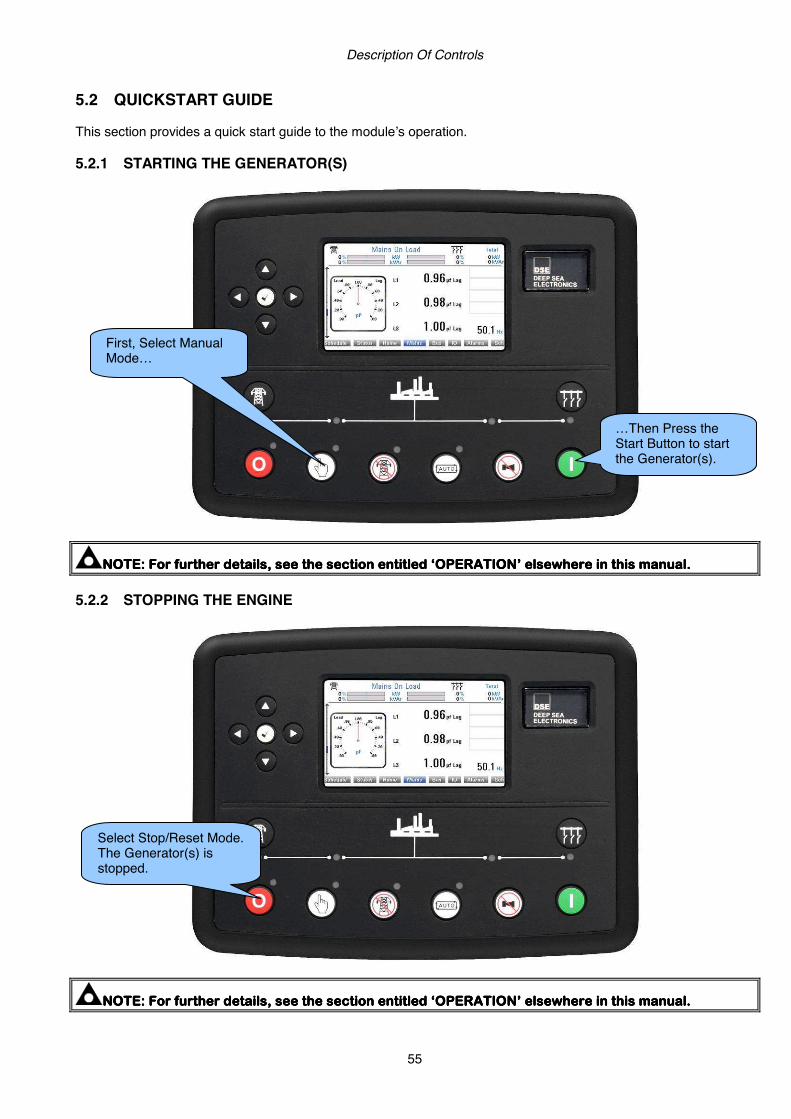
Description Of Controls
55
5.2 QUICKSTART GUIDE This section provides a quick start guide to the module’s operation. 5.2.1 STARTING THE GENERATOR(S)
NOTE:NOTE:NOTE:NOTE: For further details, see the section entitled ‘OPERATION’ elsewhere in thFor further details, see the section entitled ‘OPERATION’ elsewhere in thFor further details, see the section entitled ‘OPERATION’ elsewhere in thFor further details, see the section entitled ‘OPERATION’ elsewhere in this manual.is manual.is manual.is manual. 5.2.2 STOPPING THE ENGINE
NOTE:NOTE:NOTE:NOTE: For further details, see the section entitled ‘OPERATION’ elsewhere in this manual.For further details, see the section entitled ‘OPERATION’ elsewhere in this manual.For further details, see the section entitled ‘OPERATION’ elsewhere in this manual.For further details, see the section entitled ‘OPERATION’ elsewhere in this manual.
First, Select Manual Mode…
…Then Press the Start Button to start the Generator(s).
Select Stop/Reset Mode. The Generator(s) is stopped.

Description Of Controls
56
5.3 VIEWING THE INSTRUMENT PAGES 5.3.1 DISPLAY OVERVIEW
5.3.2 PAGE INDICATORS
Alarms Schedule Status Home Mains Bus I/O
Pressing the next / previous page buttons scrolls between the available pages. ExampleExampleExampleExample
Alarms Schedule Status Home Mains Bus I/O
Press Page Right to move to the next page.
Schedule Status Home Mains Bus I/O Alarms
Press Page Right to move to the next page.
Status Home Mains Bus I/O Alarms Schedule
It May be Quicker to Scroll Left Through the Pages Rather Than Right!
The Bottom Line of the Instrument Display Indicates the Currently Selected Page
Main Instrumentation Display
Side Scroll Bar
The Top Section shows a configurable Summary of the Status

Description Of Controls
57
5.3.3 SIDE SCROLL BAR While a page is being viewed, the scroll bar at the side of the display represents how ‘far down’ the page you are
currently viewing. Pressing the scroll buttons moves up and down the currently selected page. ExamplesExamplesExamplesExamples
The complete order and contents of each information page are given in the following sections Once selected the page will remain on the LCD display until the user selects a different page, or after an extended period of inactivity (configurable page timer), the module will revert to the status display. 5.3.4 SUMMARY AREA 5.3.4.1 WHEN CONFIGURED TO SHOW LOAD SWITCH
5.3.4.2 WHEN CONFIGURED TO SHOW BAR GRAPHS
5.3.4.3 DURING SYNCHRONISING
An all grey vertical bar shows there is no further information to display, the whole page is currently being displayed.
The blue section indicates that you are currently viewing the ‘bottom’ half of a page. Press scroll up/down to move through the page
The blue section indicates that you are currently viewing a small part of a page. Press scroll up/down to move through the page
Load Switch Position
Bus Available LED Actual Mains Loading
Mains and Bus Loading as a Percentage of Full Load
Voltage and Frequency difference between the supplies. The ‘Tick’ displays if the parameter is within the check sync window.
Phase difference of the two Supplies. The ‘Barred’ Section is the Configurable Phase Window.
Mains Available LED
Actual Mains Loading
Actual Mains Loading

Description Of Controls
58
5.3.5 HOME In addition to the common display area, the following instruments are displayed on the home page.
Pressing the scroll buttons moves up and down the pages mentioned below. Example image :
Mains
• Mains Voltage (ph-N) • Mains Voltage (ph-ph) • Mains Current • Mains Load (kW) • Mains Load (kV A) • Mains Power Factor • Mains Load (kV Ar)
Bus
• Bus Voltage (ph-N) • Bus Voltage (ph-ph) • Bus/Load CT Current (L1) • Bus/Load CT Load (kW L1) • Bus/Load CT Load (kVA L1) • Bus/Load CT Load (kVAr L1) • Bus/Load CT Power Factor (L1)

Description Of Controls
59
Bus/Mains Mode
• kW Bus/Mains Actual (% of Total) • kW Bus/Mains Target (% of Total) • kVAr Bus/Mains Actual (% of Total) • kVAr Bus/Mains Target (% of Total) • Ramp %
Mains Supply Information
• Mains Average Voltage (ph-N) • Mains Phase Rotation • Mains AC System • Mains Nominal Settings (Hz & Voltage)
Bus Supply Information
• Bus Average Voltage (ph-N) • Bus Phase Rotation • Bus AC System • Bus Nominal Settings (Hz & Voltage)
Sets on Bus/Load
• Sets on Bus/Load (Number of Sets on Bus/Load / Number of Sets on the MSC Link) • ID (MSC ID number and LCD Indicator to show if set is closed onto the Bus/Load)
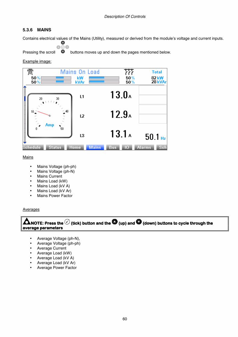
Description Of Controls
60
5.3.6 MAINS Contains electrical values of the Mains (Utility), measured or derived from the module’s voltage and current inputs.
Pressing the scroll buttons moves up and down the pages mentioned below. Example image:
Mains
• Mains Voltage (ph-ph) • Mains Voltage (ph-N) • Mains Current • Mains Load (kW) • Mains Load (kV A) • Mains Load (kV Ar) • Mains Power Factor
Averages
NOTNOTNOTNOTE: Press the E: Press the E: Press the E: Press the ((((ttttickickickick)))) buttonbuttonbuttonbutton and and and and the the the the (up) and (up) and (up) and (up) and (down) buttons to cycle through the (down) buttons to cycle through the (down) buttons to cycle through the (down) buttons to cycle through the average parametersaverage parametersaverage parametersaverage parameters
• Average Voltage (ph-N), • Average Voltage (ph-ph) • Average Current • Average Load (kW) • Average Load (kV A) • Average Load (kV Ar) • Average Power Factor

Description Of Controls
61
AC System
• Mains Configuration (AC System diagram) • Mains Configuration (Nominals)
Accumulated
• Mains kW h + • Mains kW h - • Mains kV A h • Mains kV Ar h
Total
• Mains Total Load (kW, kV A, kV Ar, Power Factor) Mains Decoupling
• R.O.C.O.F (Instantaneous reading and peak hold) • Vector Shift (Instantaneous reading and peak hold)

Description Of Controls
62
5.3.7 BUS Contains electrical values of the common generator bus, this is derived from the MSC link which connects all the modules together.
Pressing the scroll buttons moves up and down the pages mentioned below. Example image:
Bus
• Bus Voltage (ph-N) • Bus Voltage (ph-ph) • Bus/Load CT Current (L1) • Bus/Load CT Load (kW L1) • Bus/Load CT Load (kVA L1) • Bus/Load CT Load (kVAr L1) • Bus/Load CT Power Factor (L1)
Description Of Controls
63
Averages
NOTE: PresNOTE: PresNOTE: PresNOTE: Press the s the s the s the ((((ttttickickickick)))) buttonbuttonbuttonbutton and and and and the the the the (up) and (up) and (up) and (up) and (down) buttons to cycle through the (down) buttons to cycle through the (down) buttons to cycle through the (down) buttons to cycle through the average parametersaverage parametersaverage parametersaverage parameters
• Average Voltage (ph-N), • Average Voltage (ph-ph) • Average Current (L1) • Average Load (kW L1) • Average Load (kVA L1) • Average Load (kVAr L1) • Average Power Factor (L1)
AC System
• Bus Configuration (AC System diagram) • Bus Configuration (Nominals)
Bus Load
• Bus Load (kW and Total %) • Bus Load (kV Ar and Total %)

Description Of Controls
64
5.3.8 I/O Displays the measured values of the analogue inputs C and D.
Pressing the scroll buttons moves up and down the pages mentioned below. Example image:
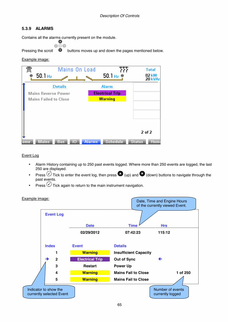
Description Of Controls
65
5.3.9 ALARMS Contains all the alarms currently present on the module.
Pressing the scroll buttons moves up and down the pages mentioned below. Example image:
Event Log
• Alarm History containing up to 250 past events logged. Where more than 250 events are logged, the last 250 are displayed.
• Press Tick to enter the event log, then press (up) and (down) buttons to navigate through the past events.
• Press Tick again to return to the main instrument navigation. Example image:
Event Log
Date Time Hrs
02/29/2012 07:42:23 115:12 Index Event Details 1 Warning Insufficient Capacity 2 Electrical Trip Out of Sync
3 Restart Power Up
4 Warning Mains Fail to Close 1 of 250 5 Warning Mains Fail to Close
Date, Time and Engine Hours of the currently viewed Event.
Indicator to show the currently selected Event
Number of events currently logged

Description Of Controls
66
5.3.10 SCHEDULE Contains the scheduler settings for the controller.
Pressing the scroll buttons moves up and down the pages mentioned below. Example images:
5.3.11 STATUS Contains status information for the controller.
Pressing the scroll buttons moves up and down the pages mentioned below. Depending upon configuration of the controller, the information displayed will change.
Information Model 8860 USB ID 0x0000BC12563 Control V1.00.02 Graphics V1.00.03 Analogue V3.00.02 Engine V1.18 Bootloader Control V1.00 Bootloader Graphics V1.02.03
This section contains important information about the module and the firmware versions. This information may be asked for when contacting DSE Technical Support Department for advice.

Description Of Controls
67
RS232 No Modem
Slave ID 10 Baud Rate 115200 Tx Packets 1562 Rx Packets 1562 Exception Packets 3
This section is included to give information about the RS232 serial port and external modem (if connected). The items displayed on this page will change depending upon configuration of the module. You are referred to your system supplier for further details.
NOTE:NOTE:NOTE:NOTE: Factory Default settings are for the RS232 port to be enabled with no modem connected, Factory Default settings are for the RS232 port to be enabled with no modem connected, Factory Default settings are for the RS232 port to be enabled with no modem connected, Factory Default settings are for the RS232 port to be enabled with no modem connected, operating at 19operating at 19operating at 19operating at 19200 baud, modbus slave address 10.200 baud, modbus slave address 10.200 baud, modbus slave address 10.200 baud, modbus slave address 10. Example 1 – Module connected to an RS232 telephone modem. When the module is powered up, it will send ‘initialisation strings’ to the connected modem. It is important therefore that the modem is already powered, or is powered up at the same time as the module. At regular intervals after power up, the modem is reset, and reinitialised, to ensure the modem does not ‘hang up’. If the module does not correctly communicate with the modem, “Modem initialising’ appears on the Serial Port instrument screen as shown overleaf. If the module is set for “incoming calls” or for “incoming and outgoing calls”, then if the modem is dialled, it will answer after two rings (using the factory setting ‘initialisation strings)’. Once the call is established, all data is passed from the dialling PC and the module. If the module is set for “outgoing calls” or for “incoming and outgoing calls”, then the module will dial out whenever an alarm is generated. Note that not all alarms will generate a dial out; this is dependant upon module configuration of the event log. Any item configured to appear in the event log will cause a dial out. Many GSM modems are fitted with a status LED to show operator cell status and ringing indicator. These can be a useful troubleshooting tool. In the case of GSM connection problems, try calling the DATA number of the SIMCARD with an ordinary telephone. There should be two rings, followed by the modem answering the call and then ‘squealing’. If this does not happen, you should check all modem connections and double check with the SIM provider that it is a DATA SIM and can operate as a data modem. DATA is NOT the same as FAX or GPRS and is often called Circuit Switched Data (CSD) by the SIM provider.
NOTE: In theNOTE: In theNOTE: In theNOTE: In the case of GSM modems, it is important that a DATA ENABLED SIM is used. This is often case of GSM modems, it is important that a DATA ENABLED SIM is used. This is often case of GSM modems, it is important that a DATA ENABLED SIM is used. This is often case of GSM modems, it is important that a DATA ENABLED SIM is used. This is often a different number than the ‘voice number’ and is often called Circuit Switched Data (CSD) by the SIM a different number than the ‘voice number’ and is often called Circuit Switched Data (CSD) by the SIM a different number than the ‘voice number’ and is often called Circuit Switched Data (CSD) by the SIM a different number than the ‘voice number’ and is often called Circuit Switched Data (CSD) by the SIM provider.provider.provider.provider.
If the GSM modem is not purchased from DSE, ensure that it has been correctly set to operate at 9600 baud. The DSE Modbus Gencomm document containing register mappings inside the DSE module is available upon request from [email protected]. Email your request along with the serial number of your DSE module to ensure the correct information is sent to you.

Description Of Controls
68
RS485 Port 1 / Port 2
Slave ID 10 Baud Rate 115200 Tx Packets 1562 Rx Packets 1562 Exception Packets 3
This section is included to give information about the currently selected serial port and external modem (if connected). The items displayed on this page will change depending upon configuration of the module. You are referred to your system supplier for further details.
NOTE:NOTE:NOTE:NOTE: Factory Default settings are for the RS485 port to operating atFactory Default settings are for the RS485 port to operating atFactory Default settings are for the RS485 port to operating atFactory Default settings are for the RS485 port to operating at 19200 baud, modbus slave 19200 baud, modbus slave 19200 baud, modbus slave 19200 baud, modbus slave address 10.address 10.address 10.address 10.
Module RS485 port configured for connection to a modbus master. The modules operate as a modbus RTU slave device. In a modbus system, there can be only one Master, typically a PLC, HMI system or PC SCADA system. This master requests for information from the modbus slave (The module) and may (in control systems) also send request to change operating modes etc. Unless the Master makes a request, the slave is ‘quiet’ on the data link. The factory settings are for the module to communicate at 19200 baud, modbus slave address 10. The DSE Modbus Gencomm document containing register mappings inside the DSE module is available upon request from [email protected]. Email your request along with the serial number of your DSE module to ensure the correct information is sent to you. Typical requests (using Pseudo code) BatteryVoltage=ReadRegister(10,0405,1) : reads register (hex) 0405 as a single register (battery volts) from slave address 10. WriteRegister(10,1008,2,35701, 65535-35701) : Puts the module into AUTO mode by writing to (hex) register 1008, the values 35701 (auto mode) and register 1009 the value 65535-35701 (the bitwise opposite of auto mode) Shutdown=(ReadRegister(10,0306,1) >> 12) & 1) : reads (hex) 0306 and looks at bit 13 (shutdown alarm present) Warning=(ReadRegister(10,0306,1) >> 11) & 1) : reads (hex) 0306 and looks at bit 12 (Warning alarm present) ElectricalTrip=(ReadRegister(10,0306,1) >> 10) & 1) : reads (hex) 0306 and looks at bit 11 (Electrical Trip alarm present) ControlMode=ReadRegister(10,0304,2); reads (hex) register 0304 (control mode).
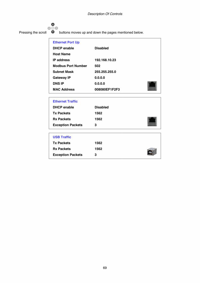
Description Of Controls
69
Pressing the scroll buttons moves up and down the pages mentioned below.
Ethernet Port Up
DHCP enable Disabled Host Name IP address 192.168.10.23 Modbus Port Number 502 Subnet Mask 255.255.255.0 Gateway IP 0.0.0.0 DNS IP 0.0.0.0 MAC Address 008080EF1F2F3
Ethernet Traffic
DHCP enable Disabled Tx Packets 1562 Rx Packets 1562 Exception Packets 3
USB Traffic
Tx Packets 1562 Rx Packets 1562 Exception Packets 3
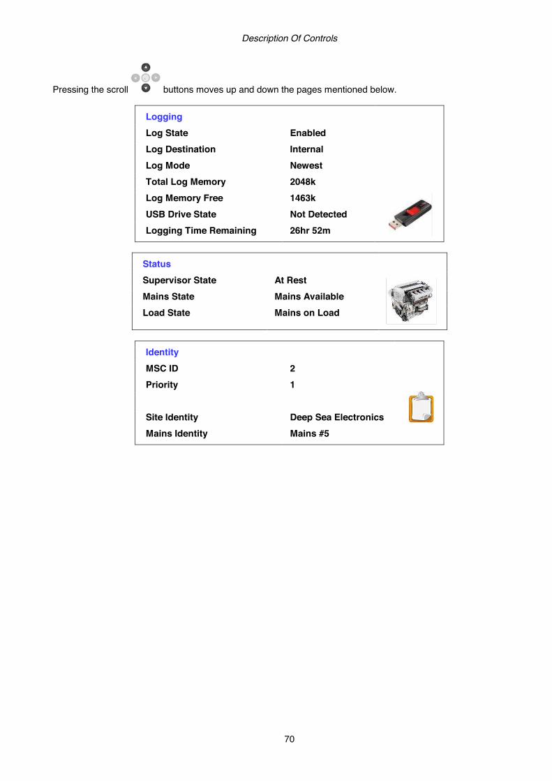
Description Of Controls
70
Pressing the scroll buttons moves up and down the pages mentioned below.
Logging
Log State Enabled Log Destination Internal Log Mode Newest Total Log Memory 2048k Log Memory Free 1463k USB Drive State Not Detected Logging Time Remaining 26hr 52m
Status
Supervisor State At Rest Mains State Mains Available Load State Mains on Load
Identity
MSC ID 2 Priority 1 Site Identity Deep Sea Electronics Mains Identity Mains #5

Operation and Indications
71
6 FACIA OPERATION 6.1 CONTROL Control of the module is via push buttons mounted on the front of the module with STOP/RESET, MANUAL, TEST, AUTO, ALARM MUTE and START functions. For normal operation, these are the only controls which need to be operated. The smaller push buttons are used to access further information such as generator voltage or to change the state of the load switching devices when in manual mode. Details of their operation are provided later in this document. The following descriptions detail the sequences followed by a module containing the standard ‘factory configuration’. Always refer to your configuration source for the exact sequences and timers observed by any particular module in the field.
CAUTION:CAUTION:CAUTION:CAUTION: The modThe modThe modThe module may instruct ule may instruct ule may instruct ule may instruct the generator(s) tothe generator(s) tothe generator(s) tothe generator(s) to start event due to external influences. start event due to external influences. start event due to external influences. start event due to external influences. Therefore, it is possible for the engine to start at any time without warning. Prior to performing any Therefore, it is possible for the engine to start at any time without warning. Prior to performing any Therefore, it is possible for the engine to start at any time without warning. Prior to performing any Therefore, it is possible for the engine to start at any time without warning. Prior to performing any maintenance on the system, it is recommended that steps are taken to remove maintenance on the system, it is recommended that steps are taken to remove maintenance on the system, it is recommended that steps are taken to remove maintenance on the system, it is recommended that steps are taken to remove the battery and isolate the battery and isolate the battery and isolate the battery and isolate supplies.supplies.supplies.supplies.
NOTE: NOTE: NOTE: NOTE: This controlThis controlThis controlThis control modulemodulemodulemodule has PLC functionality built in.has PLC functionality built in.has PLC functionality built in.has PLC functionality built in. This can have change the standard This can have change the standard This can have change the standard This can have change the standard operation when used.operation when used.operation when used.operation when used. ((((Default configuration the no PLC is set. Default configuration the no PLC is set. Default configuration the no PLC is set. Default configuration the no PLC is set. Refer to DSE8860 PC Software Refer to DSE8860 PC Software Refer to DSE8860 PC Software Refer to DSE8860 PC Software Configuration Manual (DSE part 057Configuration Manual (DSE part 057Configuration Manual (DSE part 057Configuration Manual (DSE part 057----174) for further details on configuring,174) for further details on configuring,174) for further details on configuring,174) for further details on configuring,
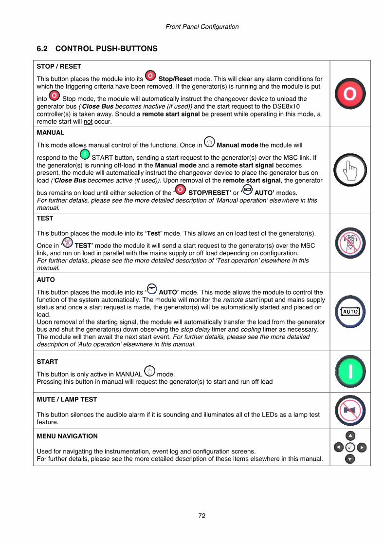
Front Panel Configuration
72
6.2 CONTROL PUSH-BUTTONS STOP / RESET
This button places the module into its Stop/Reset mode. This will clear any alarm conditions for which the triggering criteria have been removed. If the generator(s) is running and the module is put
into Stop mode, the module will automatically instruct the changeover device to unload the generator bus (‘Close Bus becomes inactive (if used)) and the start request to the DSE8x10 controller(s) is taken away. Should a remote start signal be present while operating in this mode, a remote start will not occur.
MANUAL
This mode allows manual control of the functions. Once in Manual mode the module will
respond to the START button, sending a start request to the generator(s) over the MSC link. If the generator(s) is running off-load in the Manual mode and a remote start signal becomes present, the module will automatically instruct the changeover device to place the generator bus on load (‘Close Bus becomes active (if used)). Upon removal of the remote start signal, the generator
bus remains on load until either selection of the ‘ STOP/RESET’ or ‘ AUTO’ modes. For further details, please see the more detailed description of ‘Manual operation’ elsewhere in this manual.
TEST This button places the module into its ‘Test’ mode. This allows an on load test of the generator(s).
Once in ‘ TEST’ mode the module it will send a start request to the generator(s) over the MSC link, and run on load in parallel with the mains supply or off load depending on configuration. For further details, please see the more detailed description of ‘Test operation’ elsewhere in this manual.
AUTO
This button places the module into its ‘ AUTO’ mode. This mode allows the module to control the function of the system automatically. The module will monitor the remote start input and mains supply status and once a start request is made, the generator(s) will be automatically started and placed on load. Upon removal of the starting signal, the module will automatically transfer the load from the generator bus and shut the generator(s) down observing the stop delay timer and cooling timer as necessary. The module will then await the next start event. For further details, please see the more detailed description of ‘Auto operation’ elsewhere in this manual.
START
This button is only active in MANUAL mode. Pressing this button in manual will request the generator(s) to start and run off load MUTE / LAMP TEST This button silences the audible alarm if it is sounding and illuminates all of the LEDs as a lamp test feature.
MENU NAVIGATION Used for navigating the instrumentation, event log and configuration screens. For further details, please see the more detailed description of these items elsewhere in this manual.

Protections
73
CLOSE MAINS
This push button is used to control the closure of the mains load switching device in Manual mode and has two modes of operation : ‘Normal’ breaker button control
• Synchronising is NOT enabled: Pressing this button when the mains is available and off
load in MANUAL mode, the bus load switch is opened and the mains load switch is closed. Further presses of this button will have no effect.
• Synchronising is enabled: Pressing this button when the mains is available, in
MANUAL mode and the mains load switch open, the controller will synchronise with the Bus. The mains load switch is then closed in parallel with the Bus. Further presses of this button will ramp all the load from the generator bus and once done, open the bus load switch leaving just the mains supplying the load.
‘Alternative’ breaker button control
• Synchronising is NOT enabled: Pressing this button when the mains is available and off
load in MANUAL mode, the bus load switch is opened and the mains load switch is closed. Further presses of this button will open and close the mains load switch and leave the bus load switch in the open position.
• Synchronising is enabled: Pressing this button when the mains is available, in MANUAL mode and the mains load switch open, the controller will synchronise with the Bus. The mains load switch is then closed in parallel with the Bus. Further presses of this button will ramp all the load onto the generator bus and once done, open the mains load switch leaving just the generator bus supplying the load.
CLOSE BUS
This push button is used to control the closure of the generator load switching device in Manual mode and has two modes of operation : ‘Normal’ breaker button control
• Synchronising is NOT enabled: Pressing this button when the generator bus is available
and off load in MANUAL mode, the mains load switch is opened and the generator bus load switch is closed. Further presses of this button will have no effect.
• Synchronising is enabled: Pressing this button when the generator bus is available, in
MANUAL mode and the generator bus load switch is open, the controller will synchronise the generator(s) to the Mains. The generator load switch is then closed in parallel with the Mains. Further presses of this button will ramp the entire load from mains and once done, open the mains load switch leaving just the generator(s) supplying the load.
‘Alternative’ breaker button control
• Synchronising is NOT enabled: Pressing this button when the generator bus is available
and off load in MANUAL mode, the bus load switch is closed and the mains load switch is opened. Further presses of this button will open and close the generator bus load switch and leave the mains load switch in the open position.
• Synchronising is enabled: Pressing this button when the generator bus available, in
MANUAL mode and the generator bus load switch open, the controller will synchronise the generator(s) to the mains, the mains load switch is then closed in parallel with the Bus. Further presses of this button will ramp the entire load onto the mains and once done, open the generator bus load switch leaving just the mains supplying the load.
Front Panel Configuration
74
7 OPERATING PROCEDURE The following description details the sequences followed by a module containing the standard ‘factory configuration’. Remember that if you have purchased a completed generator set or control panel from your supplier, the module’s configuration will probably have been changed by them to suit their particular requirements. Always refer to your configuration source for the exact sequences and timers observed by any particular module in the field. 7.1 STOP MODE
NOTE: NOTE: NOTE: NOTE: If a digital input configured to If a digital input configured to If a digital input configured to If a digital input configured to panel lockpanel lockpanel lockpanel lock is active, is active, is active, is active, changing module modes will not be changing module modes will not be changing module modes will not be changing module modes will not be possible. Viewing the instrumpossible. Viewing the instrumpossible. Viewing the instrumpossible. Viewing the instruments and event logs is NOT affected by panel lock.ents and event logs is NOT affected by panel lock.ents and event logs is NOT affected by panel lock.ents and event logs is NOT affected by panel lock.
Activate auto mode by pressing the pushbutton. An LED indicator beside the button confirms this action. In STOP mode, the module will remove the generator bus from load (if necessary) before removing the start request from the engines. Any latched alarms (electrical trip) that have been cleared are reset when STOP mode is entered. The generator(s) will not be started by the DSE8860 when in STOP mode. If remote start signals are given or the mains supply fails, the start request is not sent to the generator(s) until AUTO mode is entered. If Immediate mains dropout is enabled, the mains load switch is opened and closed as appropriate, when the mains fails or becomes available to take load.

Protections
75
7.2 AUTOMATIC MODE
NOTENOTENOTENOTE: : : : If a digital input configured to If a digital input configured to If a digital input configured to If a digital input configured to panel lockpanel lockpanel lockpanel lock is active, is active, is active, is active, changing module modes will not be changing module modes will not be changing module modes will not be changing module modes will not be possible. Viewing the instruments and event logs is NOT affected by panel lock. possible. Viewing the instruments and event logs is NOT affected by panel lock. possible. Viewing the instruments and event logs is NOT affected by panel lock. possible. Viewing the instruments and event logs is NOT affected by panel lock.
Activate auto mode by pressing the pushbutton. An LED indicator beside the button confirms this action. Auto mode will allow the generator(s) to operate fully automatically, starting and stopping as required with no user intervention.
7.2.1 WAITING IN AUTO MODE If a starting request is made, the starting sequence will begin. Starting requests can be from the following sources:
• Mains supply out of limits • High mains load (when the DSE8860 is configured for an automatic peak lopping system) • Activation of an auxiliary input that has been configured to remote start on load, remote start in island mode
or remote start off load. • Activation of an auxiliary input that has been configured to Aux Mains Failure. • Activation of the inbuilt exercise scheduler. • Instruction from external remote telemetry devices using the RS232, RS485 or Ethernet interface.
7.2.2 STARTING SEQUENCE To allow for ‘false’ start requests such as mains brownouts, the start delay timer begins. There are individual start delay timers for each of the different start request types. Should all start requests be removed during the start delay timer, the unit will return to a stand-by state. If a start request is still present at the end of the start delay timer, the starting request is sent to the generator(s) over the MSC data link.

Front Panel Configuration
76
7.2.3 BUS AVAILABLE (GENERATOR(S) RUNNING) Once the generator bus becomes available, the load is transferred. If required, the generator bus is first synchronised with the mains supply. This operation is automatic, using the MSC data link. Load ramping takes place when appropriate, the DSE8860 controls the generator bus to provide the configured power to the load and/or mains supply. 7.2.3.1 BUS MODE
In this mode, the generator(s) are used to provide a fixed amount of active power (kW), this is configured into the Load parallel power parameter.
How much reactive power is provided depends upon the kVAr/pf selection: • kVAr – The generator(s) will provide the number of kVAr configured into the Load Parallel VAr parameter.
The power factor is variable in order to achieve this.
• Pf – The generator(s) will produce power at the power factor configured into the Load power factor parameter. The kVAr is variable in order to achieve this.
7.2.3.2 MAINS MODE
In this mode, the generator(s) are used to provide a variable amount of active power (kW), to maintain the mains import/export levels at the configured values. This is configured into the Load parallel power parameter. How much reactive power is taken from or exported to the mains depends upon the kVAr/pf selection:
• KVAr – The generator(s) will be used to provide enough kVAr to keep the mains import/export VAr at the level configured into the Load Parallel VAr parameter. The mains power factor is variable in order to achieve this.
• Pf – The generator(s) will be used to provide enough kVAr to keep the mains import/export at the power
factor configured into the Load power factor parameter. The mains kVAr is variable in order to achieve this. As the load increases and decreases, sets may automatically start and stop, depending upon their configuration. If all start requests are removed, the stopping sequence will begin. 7.2.4 STOPPING SEQUENCE The return delay timer operates to ensure that the starting request has been permanently removed and is not just a short-term removal. If there are no starting requests at the end of the return delay timer, the load is transferred back from the generator bus to the mains supply and the start request is removed from the generator(s).

Protections
77
7.3 MANUAL MODE
NOTE:NOTE:NOTE:NOTE: If a digital input configured to If a digital input configured to If a digital input configured to If a digital input configured to panel lockpanel lockpanel lockpanel lock is active, is active, is active, is active, changing module mochanging module mochanging module mochanging module modes will not be des will not be des will not be des will not be possible. Viewing the instruments and event logs is NOT affected by panel lock. possible. Viewing the instruments and event logs is NOT affected by panel lock. possible. Viewing the instruments and event logs is NOT affected by panel lock. possible. Viewing the instruments and event logs is NOT affected by panel lock.
Activate Manual mode be pressing the pushbutton. An LED indicator beside the button confirms this action. Manual mode allows the operator to start and stop the generator(s) manually, and if required change the state of the load switching devices.
7.3.1 WAITING IN MANUAL MODE When in manual mode, the generator(s) will not start automatically.
To begin the starting sequence, press the button. 7.3.2 BUS AVAILABLE (GENERATOR(S) RUNNING) In manual mode, the load is not transferred to the generator bus unless a ‘loading request’ is made. A loading request can come from a number of sources.
• Pressing the transfer to bus button • Mains supply out of limits. • Activation of an auxiliary input that has been configured to remote start on load, remote start in island mode
or remote start off load. • Activation of an auxiliary input that has been configured to Aux Mains Failure. • Activation of the inbuilt exercise scheduler if configured for ‘on load’ runs.
Parallel operation is governed by configuration. See the previous section Auto Mode: Bus Available (Generator(s) Running) for further details. Once bus and mains are in parallel, you can either
• Press the transfer to bus button. The load is ramped to the bus, the mains breaker is opened.
• Press the transfer to mains button. The load is transferred to the mains. The generator bus breaker is opened.
• Press the auto mode button to return to automatic mode. 7.3.3 STOPPING SEQUENCE In manual mode, the set will continue to run until either:
• The stop button is pressed – The generator(s) are requested to stop
• The auto button is pressed. The generator(s) will observe all auto mode start requests and stopping timers before beginning the Auto Mode: Stopping Sequence.

Front Panel Configuration
78
7.4 TEST MODE
NOTE:NOTE:NOTE:NOTE: If a digital input configured to If a digital input configured to If a digital input configured to If a digital input configured to panel lockpanel lockpanel lockpanel lock is active, is active, is active, is active, changing module modes will not be changing module modes will not be changing module modes will not be changing module modes will not be possible. Viewing the instruments and event logs is NOT affected by panel lock. possible. Viewing the instruments and event logs is NOT affected by panel lock. possible. Viewing the instruments and event logs is NOT affected by panel lock. possible. Viewing the instruments and event logs is NOT affected by panel lock.
Activate test mode be pressing the pushbutton. An LED indicator beside the button confirms this action. Test mode will start the generator(s) and parallel the mains to the generator bus to provide a Test on load function. Depending upon configuration this can be continuous parallel or island mode operation.
7.4.1 WAITING IN TEST MODE As soon as test mode is entered, the generator(s) will start automatically. 7.4.2 BUS AVAILABLE (GENERATOR(S) RUNNING) Parallel operation is governed by configuration. See the previous section entitled Auto Mode: Bus Available (Generator(s) Running) for further details. In test mode, the set will continue to run on load until either:
• The stop button is pressed – The generator bus breaker is opened and the generator(s) is called to stop.
• The auto button is pressed. The generator(s) will observe all auto mode start requests and stopping timers before beginning the Auto Mode: Stopping Sequence.

Protections
79
7.5 MULTIPLE MAINS OPERATION In a multiple mains system, the generator(s) are controlled by more than one DSE8860 mains controller and used to provide power to multiple loads. Should one or more of the mains supplies fail, the generator(s) (controlled by DSE8x10 modules) are started and supply power to the load. If more than one mains supply has failed, the loads are transferred to the generator(s) one by one. The DSE8x10 controllers share power equally on a percentage basis with the other generators in the system.
• If one mains supply returns, the DSE8860 connected to that mains supply will synchronise the generator(s) with the mains and affect a no-break changeover. The generator(s) continue to supply power to the remaining loads.
• If more than one mains supply returns at the same time, then the DSE8860 with the highest priority will take control of the generator(s) and affect a no-break changeover back to the mains supply. The remaining DSE8860s will operate in priority order providing no-break returns back to their respective mains supplies.
If the generator(s) are ‘peak-lopping’ with one mains supply, and another mains supply fails, dependent upon module configuration, the generator(s) will either:
• Continue to peak-lop as before. The load with the mains supply that has failed will remain without power. • Cease peak-lopping and backup the failed mains supply.
NOTE: NOTE: NOTE: NOTE: At no time are the generators paralleled with more than one mains supply at a time. At no time are the generators paralleled with more than one mains supply at a time. At no time are the generators paralleled with more than one mains supply at a time. At no time are the generators paralleled with more than one mains supply at a time. Paralleling with mains supplies is always taken in turn.Paralleling with mains supplies is always taken in turn.Paralleling with mains supplies is always taken in turn.Paralleling with mains supplies is always taken in turn. 7.5.1 DSE8X60 PRIORITY
Where more than one DSE8x60 controller is present, they must determine which one is to take control over the generator(s). The following table shows how this priority decision is made.
Priority Condition HIGHEST
Auto mode, mains failed, bus not on load Auto mode, mains has returned Auto mode, mains failed, bus on load Auto mode, mains available, requesting control over generators Test on load mode Manual mode, sets running or about to run (start button has been pressed) Auto mode, mains available Manual mode, sets not running (waiting for start button to be pressed) Stop mode
LOWEST Where two or more DSE8x60 controllers have the same conditions in the table above, the ‘Set Priority’ configuration setting comes into effect. If two or more DSE8x60 controllers have the same priority number, an electrical trip alarm is generated - Priority Selection Error - and the priority numbers must be changed before the system will operate.
NOTE: NOTE: NOTE: NOTE: ---- If a If a If a If a DSE8xDSE8xDSE8xDSE8x60 requests to control the generators (either automatically or manually) it will not 60 requests to control the generators (either automatically or manually) it will not 60 requests to control the generators (either automatically or manually) it will not 60 requests to control the generators (either automatically or manually) it will not be allowed to do so until higher priority be allowed to do so until higher priority be allowed to do so until higher priority be allowed to do so until higher priority DDDDSESESESE8888XXXX60 controllers have relinquished control over them.60 controllers have relinquished control over them.60 controllers have relinquished control over them.60 controllers have relinquished control over them.
For typical one line diagram of a multi-mains system, see the section entitled “TYPICAL SYSTEM SCHEMATICS” elsewhere in this manual.

Front Panel Configuration
80
7.5.2 DSE8860 BUS/LOAD CT The DSE8860 controller incorporates an optional (but recommended) extra CT for measuring the amount of power the generator bus is producing or the size of the load. Used in conjunction with the CTs measuring the amount of load on the mains supply, this CT allows the DSE8860 to determine what portion of the load is being supplied by the generator(s). This allows the DSE8860 to remove the generator(s) from this load when there is little or no current passing through the bus breaker. For example: When the generator(s) are ramping off load.
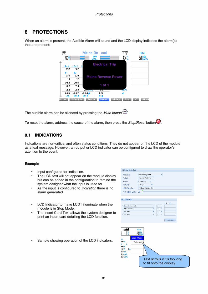
Protections
81
8 PROTECTIONS When an alarm is present, the Audible Alarm will sound and the LCD display indicates the alarm(s) that are present:
The audible alarm can be silenced by pressing the Mute button To reset the alarm, address the cause of the alarm, then press the Stop/Reset button . 8.1 INDICATIONS Indications are non-critical and often status conditions. They do not appear on the LCD of the module as a text message. However, an output or LCD indicator can be configured to draw the operator’s attention to the event. Example
• Input configured for indication. • The LCD text will not appear on the module display
but can be added in the configuration to remind the system designer what the input is used for.
• As the input is configured to Indication there is no alarm generated.
• LCD Indicator to make LCD1 illuminate when the module is in Stop Mode.
• The Insert Card Text allows the system designer to print an insert card detailing the LCD function.
• Sample showing operation of the LCD indicators.
Electrical Trip
Mains Reverse Power
1 of 1
Text scrolls if it’s too long to fit onto the display

Front Panel Configuration
82
8.2 WARNINGS Warnings are non-critical alarm conditions and do not affect the operation of the system, they serve to draw the operators attention to an undesirable condition. By default, warning alarms are self-resetting when the fault condition is removed. However enabling ‘all warnings are latched’ will cause warning alarms to latch until reset manually. This is enabled using the DSE Configuration Suite in conjunction with a compatible PC. Display Reason
Auxiliary Inputs If an auxiliary input has been configured as a warning the appropriate LCD message will be displayed and the COMMON ALARM LED will illuminate.
Battery Under Voltage The DC supply has fallen below the low volts setting level for the duration of the low battery volts timer
Battery Over Voltage The DC supply has risen above the high volts setting level for the duration of the high battery volts timer
Fail To Sync If the module cannot synchronise within the time allowed by the Synchronising timer a warning is initiated. The LCD will indicate ‘FAILED TO SYNC’ and the COMMON ALARM LED will illuminate.
Insufficient Capacity If the generator(s) reach full load when they are in parallel with the mains (utility). The LCD will indicate ‘INSUFFICIENT CAPACITY’ and the COMMON ALARM LED will illuminate.
Mains Decoupling High Frequency
If the module detects the mains frequency increase when in parallel with the generator(s) more then the configure value. The LCD will indicate ‘MAINS DECOUPLING HIGH FREQUENCY’ and the COMMON ALARM LED will illuminate.
Mains Decoupling High Voltage
If the module detects the mains voltage increase when in parallel with the generator(s) more then the configure value. The LCD will indicate ‘MAINS DECOUPLING HIGH VOLTAGE’ and the COMMON ALARM LED will illuminate.
Mains Decoupling Low Frequency
If the module detects the mains frequency decreases when in parallel with the generator(s) below the configure value. The LCD will indicate ‘MAINS DECOUPLING LOW FREQUENCY’ and the COMMON ALARM LED will illuminate.
Mains Decoupling Low Voltage
If the module detects the mains voltage decreases when in parallel with the generator(s) below the configure value. The LCD will indicate ‘MAINS DECOUPLING LOW VOLTAGE’ and the COMMON ALARM LED will illuminate.
Mains Decoupling ROCOF
If the module detects the mains frequency changing when in parallel with the generator(s) more then the configure value in a time frame. The LCD will indicate ‘MAINS DECOUPLING ROCOF’ and the COMMON ALARM LED will illuminate.
Mains Decoupling Vector Shift
If the module detects the mains phase angle changing when in parallel with the generator(s) more then the configure value in a time frame. The LCD will indicate ‘MAINS DECOUPLING VECTOR SHIFT’ and the COMMON ALARM LED will illuminate.

Protections
83
Display Reason Mains Failed To Close If the mains breaker fails to close, a warning is initiated. The LCD will
indicate ‘MAINS FAILED TO CLOSE’ and the COMMON ALARM LED will illuminate.
Mains Failed To Open If the mains breaker fails to open, a warning is initiated. The LCD will indicate ‘MAINS FAILED TO OPEN’ and the COMMON ALARM LED will illuminate.
Mains Reverse Power If the DSExx60 detects that the bus is exporting more than the configured limit, the LCD will indicate ‘MAINS REVERSE POWER’ and the COMMON ALARM LED will flash.
MSC Alarms Inhibited if an input has been configured as ‘MSC ALARMS INHIBIT’ and is active, the LCD will indicate ‘MSC ALARMS INHIBIT’ and the COMMON ALARM LED will illuminate.
MSC Data Error If the data on the MSC link is corrupt, then the LCD will indicate ‘MSC DATA ERROR’ and the COMMON ALARM LED will illuminate.
MSC Failure If the link breaks, the LCD will indicate ‘MSC FAILURE’ and the COMMON ALARM LED will illuminate.
MSC ID Error If more than one DSExx60 module is connected to the same MSC link, the LCD will indicate ‘MSC ID ERROR’ and the COMMON ALARM LED will illuminate.
MSC Too Few Sets If the number of modules on the MSC link falls below the Minimum modules on Multiset comms link, the LCD will indicate ‘MSC TOO FEW SETS’ and the COMMON ALARM LED will illuminate.
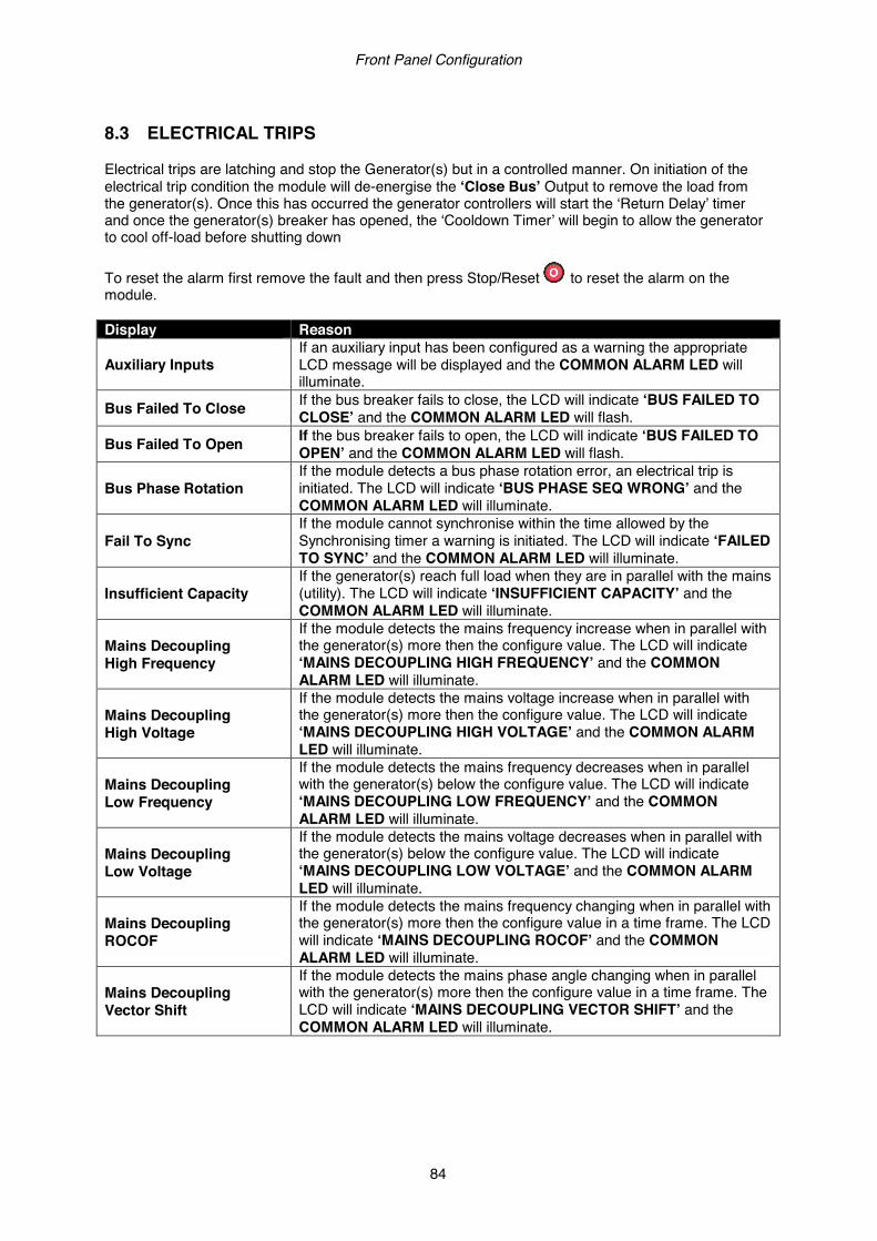
Front Panel Configuration
84
8.3 ELECTRICAL TRIPS Electrical trips are latching and stop the Generator(s) but in a controlled manner. On initiation of the electrical trip condition the module will de-energise the ‘Close Bus’ Output to remove the load from the generator(s). Once this has occurred the generator controllers will start the ‘Return Delay’ timer and once the generator(s) breaker has opened, the ‘Cooldown Timer’ will begin to allow the generator to cool off-load before shutting down To reset the alarm first remove the fault and then press Stop/Reset to reset the alarm on the module. Display Reason
Auxiliary Inputs If an auxiliary input has been configured as a warning the appropriate LCD message will be displayed and the COMMON ALARM LED will illuminate.
Bus Failed To Close If the bus breaker fails to close, the LCD will indicate ‘BUS FAILED TO CLOSE’ and the COMMON ALARM LED will flash.
Bus Failed To Open If the bus breaker fails to open, the LCD will indicate ‘BUS FAILED TO OPEN’ and the COMMON ALARM LED will flash.
Bus Phase Rotation If the module detects a bus phase rotation error, an electrical trip is initiated. The LCD will indicate ‘BUS PHASE SEQ WRONG’ and the COMMON ALARM LED will illuminate.
Fail To Sync If the module cannot synchronise within the time allowed by the Synchronising timer a warning is initiated. The LCD will indicate ‘FAILED TO SYNC’ and the COMMON ALARM LED will illuminate.
Insufficient Capacity If the generator(s) reach full load when they are in parallel with the mains (utility). The LCD will indicate ‘INSUFFICIENT CAPACITY’ and the COMMON ALARM LED will illuminate.
Mains Decoupling High Frequency
If the module detects the mains frequency increase when in parallel with the generator(s) more then the configure value. The LCD will indicate ‘MAINS DECOUPLING HIGH FREQUENCY’ and the COMMON ALARM LED will illuminate.
Mains Decoupling High Voltage
If the module detects the mains voltage increase when in parallel with the generator(s) more then the configure value. The LCD will indicate ‘MAINS DECOUPLING HIGH VOLTAGE’ and the COMMON ALARM LED will illuminate.
Mains Decoupling Low Frequency
If the module detects the mains frequency decreases when in parallel with the generator(s) below the configure value. The LCD will indicate ‘MAINS DECOUPLING LOW FREQUENCY’ and the COMMON ALARM LED will illuminate.
Mains Decoupling Low Voltage
If the module detects the mains voltage decreases when in parallel with the generator(s) below the configure value. The LCD will indicate ‘MAINS DECOUPLING LOW VOLTAGE’ and the COMMON ALARM LED will illuminate.
Mains Decoupling ROCOF
If the module detects the mains frequency changing when in parallel with the generator(s) more then the configure value in a time frame. The LCD will indicate ‘MAINS DECOUPLING ROCOF’ and the COMMON ALARM LED will illuminate.
Mains Decoupling Vector Shift
If the module detects the mains phase angle changing when in parallel with the generator(s) more then the configure value in a time frame. The LCD will indicate ‘MAINS DECOUPLING VECTOR SHIFT’ and the COMMON ALARM LED will illuminate.
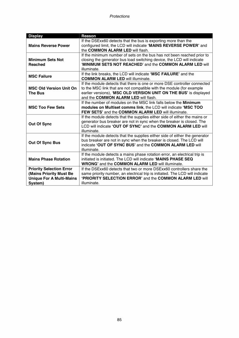
Protections
85
Display Reason
Mains Reverse Power If the DSExx60 detects that the bus is exporting more than the configured limit, the LCD will indicate ‘MAINS REVERSE POWER’ and the COMMON ALARM LED will flash.
Minimum Sets Not Reached
If the minimum number of sets on the bus has not been reached prior to closing the generator bus load switching device, the LCD will indicate ‘MINIMUM SETS NOT REACHED’ and the COMMON ALARM LED will illuminate.
MSC Failure If the link breaks, the LCD will indicate ‘MSC FAILURE’ and the COMMON ALARM LED will illuminate.
MSC Old Version Unit On The Bus
If the module detects that there is one or more DSE controller connected to the MSC link that are not compatible with the module (for example earlier versions), ‘MSC OLD VERSION UNIT ON THE BUS’ is displayed and the COMMON ALARM LED will flash.
MSC Too Few Sets If the number of modules on the MSC link falls below the Minimum modules on Multiset comms link, the LCD will indicate ‘MSC TOO FEW SETS’ and the COMMON ALARM LED will illuminate.
Out Of Sync If the module detects that the supplies either side of either the mains or generator bus breaker are not in sync when the breaker is closed. The LCD will indicate ‘OUT OF SYNC’ and the COMMON ALARM LED will illuminate.
Out Of Sync Bus If the module detects that the supplies either side of either the generator bus breaker are not in sync when the breaker is closed. The LCD will indicate ‘OUT OF SYNC BUS’ and the COMMON ALARM LED will illuminate.
Mains Phase Rotation If the module detects a mains phase rotation error, an electrical trip is initiated is initiated. The LCD will indicate ‘MAINS PHASE SEQ WRONG’ and the COMMON ALARM LED will illuminate.
Priority Selection Error (Mains Priority Must Be Unique For A Multi-Mains System)
If the DSExx60 detects that two or more DSExx60 controllers share the same priority number, an electrical trip is initiated. The LCD will indicate ‘PRIORITY SELECTION ERROR’ and the COMMON ALARM LED will illuminate.
Front Panel Configuration
86
8.4 ROCOF / VECTOR SHIFT When the mains (utility) and the generator(s) supplies are in parallel, the module monitors for a ROCOF and Vector shift trip which are set in the module’s configuration settings.
NOTE: NOTE: NOTE: NOTE: This protection operates onlyThis protection operates onlyThis protection operates onlyThis protection operates only when when when when the mains and the common generator bus the mains and the common generator bus the mains and the common generator bus the mains and the common generator bus are in parallel, itare in parallel, itare in parallel, itare in parallel, it is disabled at all other times.is disabled at all other times.is disabled at all other times.is disabled at all other times.
Should either of these alarms operate, the module will perform a controlled electrical trip of the common generator bus or a mains failure. This operation must be manually reset:
1) Press the stop button. The generator bus load switch will open, the generator(s) will be called to stop if it is still running and the alarm is also cleared.
2) Activate digital input configured to “Clear ROCOF/Vector shift” if this has been provided. 3) To clear the ROCOC / Vector Shift alarm without pressing the stop button
1) Press the (up) and (down) buttons together and hold to enter the ‘Maintenance Configuration Editor’ Editor.
2) Press the (up) or (down) buttons to cycle to the ‘Clear Mains Decouple Alarm’
option.
3) To change the action press (right) button to enter edit mode. The action is highlighted in blue to indicate selection.
4) Press the (up) button to activate the action. The action will then change to show it has
been activated.
5) Press the tick button to exit the “Maintenance Configuration Editor”.
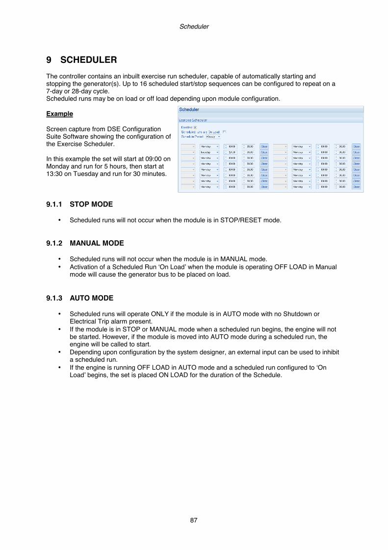
Scheduler
87
9 SCHEDULER The controller contains an inbuilt exercise run scheduler, capable of automatically starting and stopping the generator(s). Up to 16 scheduled start/stop sequences can be configured to repeat on a 7-day or 28-day cycle. Scheduled runs may be on load or off load depending upon module configuration. Example Screen capture from DSE Configuration Suite Software showing the configuration of the Exercise Scheduler. In this example the set will start at 09:00 on Monday and run for 5 hours, then start at 13:30 on Tuesday and run for 30 minutes. 9.1.1 STOP MODE
• Scheduled runs will not occur when the module is in STOP/RESET mode. 9.1.2 MANUAL MODE
• Scheduled runs will not occur when the module is in MANUAL mode. • Activation of a Scheduled Run ‘On Load’ when the module is operating OFF LOAD in Manual
mode will cause the generator bus to be placed on load. 9.1.3 AUTO MODE
• Scheduled runs will operate ONLY if the module is in AUTO mode with no Shutdown or Electrical Trip alarm present.
• If the module is in STOP or MANUAL mode when a scheduled run begins, the engine will not be started. However, if the module is moved into AUTO mode during a scheduled run, the engine will be called to start.
• Depending upon configuration by the system designer, an external input can be used to inhibit a scheduled run.
• If the engine is running OFF LOAD in AUTO mode and a scheduled run configured to ‘On Load’ begins, the set is placed ON LOAD for the duration of the Schedule.

Front Panel Configuration
88
10 FRONT PANEL CONFIGURATION
NOTE:NOTE:NOTE:NOTE: Refer to DSE8860 PC Software Configuration Manual (DSE part 057Refer to DSE8860 PC Software Configuration Manual (DSE part 057Refer to DSE8860 PC Software Configuration Manual (DSE part 057Refer to DSE8860 PC Software Configuration Manual (DSE part 057----174)174)174)174) for for for for further details on configuring, monitoring and control.further details on configuring, monitoring and control.further details on configuring, monitoring and control.further details on configuring, monitoring and control.
This configuration mode allows the operator limited customising of the way the module operates. Use the module’s navigation buttons to traverse the menu and make value changes to the parameters:
Previous Page
Increase Value / Next Item
Decrease Value / Next item
Next Page
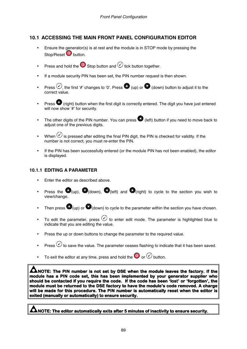
Front Panel Configuration
89
10.1 ACCESSING THE MAIN FRONT PANEL CONFIGURATION EDITOR
• Ensure the generator(s) is at rest and the module is in STOP mode by pressing the Stop/Reset button.
• Press and hold the Stop button and tick button together.
• If a module security PIN has been set, the PIN number request is then shown.
• Press , the first ‘#’ changes to ‘0’. Press (up) or (down) button to adjust it to the
correct value.
• Press (right) button when the first digit is correctly entered. The digit you have just entered will now show ‘#’ for security.
• The other digits of the PIN number. You can press (left) button if you need to move back to
adjust one of the previous digits.
• When is pressed after editing the final PIN digit, the PIN is checked for validity. If the number is not correct, you must re-enter the PIN.
• If the PIN has been successfully entered (or the module PIN has not been enabled), the editor
is displayed. 10.1.1 EDITING A PARAMETER
• Enter the editor as described above.
• Press the (up), (down), (left) and (right) to cycle to the section you wish to view/change.
• Then press (up) or (down) to cycle to the parameter within the section you have chosen.
• To edit the parameter, press to enter edit mode. The parameter is highlighted blue to
indicate that you are editing the value.
• Press the up or down buttons to change the parameter to the required value.
• Press to save the value. The parameter ceases flashing to indicate that it has been saved.
• To exit the editor at any time, press and hold the or button.
NOTE: The PIN number is not set by DSE when the module leaves the factory. If the NOTE: The PIN number is not set by DSE when the module leaves the factory. If the NOTE: The PIN number is not set by DSE when the module leaves the factory. If the NOTE: The PIN number is not set by DSE when the module leaves the factory. If the module hmodule hmodule hmodule hasasasas a PIN code set, this has been implementeda PIN code set, this has been implementeda PIN code set, this has been implementeda PIN code set, this has been implemented by your generator supplier who by your generator supplier who by your generator supplier who by your generator supplier who should be contacted if you require the code. If the code has been ‘lost’ or ‘forgotten’, the should be contacted if you require the code. If the code has been ‘lost’ or ‘forgotten’, the should be contacted if you require the code. If the code has been ‘lost’ or ‘forgotten’, the should be contacted if you require the code. If the code has been ‘lost’ or ‘forgotten’, the module must be returned to the DSE factory to have the module’s code removed. A chargemodule must be returned to the DSE factory to have the module’s code removed. A chargemodule must be returned to the DSE factory to have the module’s code removed. A chargemodule must be returned to the DSE factory to have the module’s code removed. A charge will be made for this procedure.will be made for this procedure.will be made for this procedure.will be made for this procedure. The PIN number is automatically reset when the editor is The PIN number is automatically reset when the editor is The PIN number is automatically reset when the editor is The PIN number is automatically reset when the editor is exited (manually or automatically) to ensure security.exited (manually or automatically) to ensure security.exited (manually or automatically) to ensure security.exited (manually or automatically) to ensure security.
NOTE:NOTE:NOTE:NOTE: The editor automatically exits after 5 minutes of inactivity to ensure security.The editor automatically exits after 5 minutes of inactivity to ensure security.The editor automatically exits after 5 minutes of inactivity to ensure security.The editor automatically exits after 5 minutes of inactivity to ensure security.
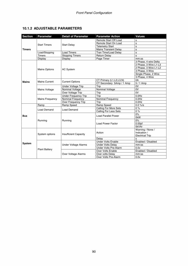
Front Panel Configuration
90
10.1.2 ADJUSTABLE PARAMETERS Section Parameter Detail of Parameter Parameter Action Values
Timers
Start Timers Start Delay
Remote Start Off Load s Remote Start On Load s Telemetry Start s Mains Transient Delay s
Load/Stopping Timers
Load Timers Tran Time/Load Delay s Stopping Timers Return Delay s
Display Display Page Timer mm:ss
Mains
Mains Options AC System
3 Phase, 4 wire Delta 2 Phase, 3 Wire L1-L3 2 Phase, 3 Wire L1-L2 3 Phase, 3 Wire Single Phase, 2 Wire 3 Phase, 4 Wire
Mains Current Current Options CT Primary (L1,L2,L3,N) 0A CT Secondary 5Amp / 1 Amp 5 / 1 Amp
Mains Voltage Under Voltage Trip Trip 0V Nominal Voltage Nominal Voltage 0V Over Voltage Trip Trip 0V
Mains Frequency Under Frequency Trip Trip 0.0Hz Nominal Frequency Nominal Frequency 0.0Hz Over Frequency Trip Trip 0.0Hz
Bus
Ramp Ramp Speed Ramp Speed 0.0 %/s
Load Demand Load Demand Calling For More Sets 0 % Calling For Less Sets 0 %
Running Running
Load Parallel Power 0% 0kW
Load Power Factor 0% 0.00pf 0kVAr
System
System options Insufficient Capacity Action Warning / None / Indication / Electrical Trip
Delay s
Plant Battery
Under Voltage Alarms Under Volts Enable Enabled / Disabled Under Volts Delay mm:ss Under Volts Pre-Alarm 0.0v
Over Voltage Alarms Over Volts Enable Enabled / Disabled Over volts Delay mm:ss Over Volts Pre-Alarm 0.0v

Front Panel Configuration
91
10.2 ACCESSING THE ‘MAINTENANCE’ CONFIGURATION EDITOR
• The ‘Maintenance’ Editor can be entered while the generator(s) is running. All protections remain active if the generator(s) is running while the Maintenance Editor is entered.
• Press the (up) and (down) buttons together and hold to enter the ‘Running’ Editor. 10.2.1 EDITING A PARAMETER
• Enter the editor as described above.
• Press the (up) or (down) buttons to cycle to the section you wish to view / change.
• To change the action press (right) button to enter edit mode. The action is highlighted in blue to indicate selection.
• Press the (up) button to activate the action. The action will then change to show it has
been activated.
• To change another action press (left) button to exit edit mode. The action is no longer highlighted in blue to indicate selection.
• Press the tick button to exit the “Maintenance Configuration Editor”.
10.2.2 ADJUSTABLE PARAMETERS Description Action Activation
USB Stick Removal Request
Press
Button
Clear AMF Alarm Clear
Min / Max Session Reset Request
Cancel Telemetry Request
Decoupling Test Mode Request
Clear Mains Decouple Alarm Request

Front Panel Configuration
92
10.3 ACCESSING THE ‘RUNNING’ CONFIGURATION EDITOR
• The ‘Running’ Editor can be entered while the generator(s) is running. All protections remain active if the generator(s) is running while the ‘Running’ Editor is entered.
• Press and hold the button to enter the ‘Running’ Editor. 10.3.1 EDITING A PARAMETER
• Enter the editor as described above.
• Press the (up), (down), (left) and (right) to cycle to the section you wish to view/change.
• Then press (up) or (down) to cycle to the parameter within the section you have chosen.
• To edit the parameter, press to enter edit mode. The parameter is highlighted blue to
indicate that you are editing the value.
• Press the up or down buttons to change the parameter to the required value.
• Press to save the value. The parameter ceases flashing to indicate that it has been saved.
• Press and hold tick button to exit the “Running Configuration Editor”. 10.3.2 ADJUSTABLE PARAMETERS Section Parameter Detail Of Parameter Values Language Language Other
English (United Kingdon)
Bus
Running Load Power Factor
0% 0.00pf 0kVAr
Load Parallel Power 0% 0kW
Options Decoupling Test Mode Disabled / Enabled Voltage Voltage Adjust 0% Frequency Frequency Adjust 0%
Display
Press/ Temp Units Pressure kPA / PSI / Bar Temperature Deg F / Deg C
Volume Units Volume Litre / Gallons US / Gallons (UK) Display LCD Backlight 0
AC Graphics AC Min / Max Enable Enabled / Disabled AC Meter Enable Enabled / Disabled THD Screen Enable Enabled / Disabled
I/O Multi Meter Mode Enabled / Disabled Alarm Alarm Alert Box Enabled / Disabled Summary Summary Area Graphic Bars / Connectors Home Commissioning Screens Enabled / Disabled
Time Module Time hh:mm:ss Module Date DD/ MM/ YYYY Date Format MM/ DD/ YYYY OR DD/ MM/ YYYY
Commissioning
93
11 COMMISSIONING 11.1 PRE-COMMISSIONING Before the system is started, it is recommended that the following checks are made:- • The unit is adequately cooled and all the wiring to the module is of a standard and rating
compatible with the system. • Check all mechanical parts are fitted correctly and that all electrical connections (including earths)
are sound. The unit DC supply is fused and connected to the battery and that it is of the correct polarity.
• Check the operation of the MSC datalink. Use the DSE Config Suite to check this on the SCADA |
BUS | MSC LINK page. Verify the number of sets on the bus. • Ensure all DSE8x10 controllers in the system have been fully commissioned using the DSE “Four
Steps to Successful Synchronising”.
• Place the DSE8860 module into STOP mode. Place the DSE8x10(s) into AUTO mode.
Initiate a start by pressing the MANUAL Mode and START button of the DSE8860. All DSE8x10’s start upon receipt of the MSC start command.
• The bus will remain off load so long as the mains supply is healthy and on load. • Press the DSE8860’s STOP button to remove the start request and stop the set(s). • Set the modules internal clock/calendar to ensure correct operation of the scheduler and event
logging functions. For details of this procedure see section entitled Front Panel Configuration. • If, despite repeated checking of the connections between the DSE8000 series controller and the
customer’s system, satisfactory operation cannot be achieved, then the customer is requested to contact the factory for further advice on:-
INTERNATIONAL TEL: +44 (0) 1723 890099 INTERNATIONAL FAX: +44 (0) 1723 893303
E-mail: [email protected] Website: www.deepseaplc.com

Fault Finding
94
12 FAULT FINDING 12.1 STARTING
SYMPTOM POSSIBLE REMEDY Unit is inoperative Read/Write configuration does not operate
• Check the battery and wiring to the unit. Check the DC supply. Check the DC fuse.
Unit shuts down • Check DC supply voltage is not above 35 Volts or below 9 Volts
• Check the operating temperature is not above 70°C. Check the DC fuse.
Fail to Start is activated on DSE8x10 after pre-set number of attempts to start
• Check wiring of fuel solenoid. Check fuel. Check battery supply. Check battery supply is present on the Fuel output of the module. Check the speed-sensing signal is present on the module’s inputs. Refer to engine manual.
Continuous starting of
generator(s) when in Auto mode.
• Check that there is no signal present on the “Remote Start” input. Check configured polarity is correct.
• Check the mains supply is available and within configured limits
Generators fail to start on receipt of Remote Start signal.
• Check Start Delay timer has timed out. • Check signal is on “Remote Start” input. Confirm correct
configuration of input is configured to be used as “Remote Start”.
• Check MSC link operation
• Check the DSE8860 and DSE8x10 controllers are in AUTO mode.
12.2 LOADING
SYMPTOM POSSIBLE REMEDY Bus will not take load • Ensure the generator available LED is lit
• Check that the output configuration is correct to drive the load switch device and that all connections are correct.
• Remember that the generaor(s) will not take load in
MANUAL mode unless the mains supply fails, a remote start on load input is present or the close generator button is pressed.
Inaccurate measurements on controller display
• Check that the CT primary, CT secondary and VT ratio settings are correct for the application.
• Check that the CTs are wired correctly with regards to the direction of current flow (p1,p2 and s1,s2) and additionally ensure that CTs are connected to the correct phase (errors will occur if CT1 is connected to phase 2).
• Remember to consider the power factor: (kW = kVA x powerfactor)
• The 8000 series controllers are true RMS measuring so gives more accurate display when compared with an ‘averaging’ meter such as an analogue panel meter or some lower specified digital multimeters.
• Accuracy of the controller is better than 1% of full scale. Voltage full scale is 333V ph-n so accuracy is ±3.33V (1% of 333V).
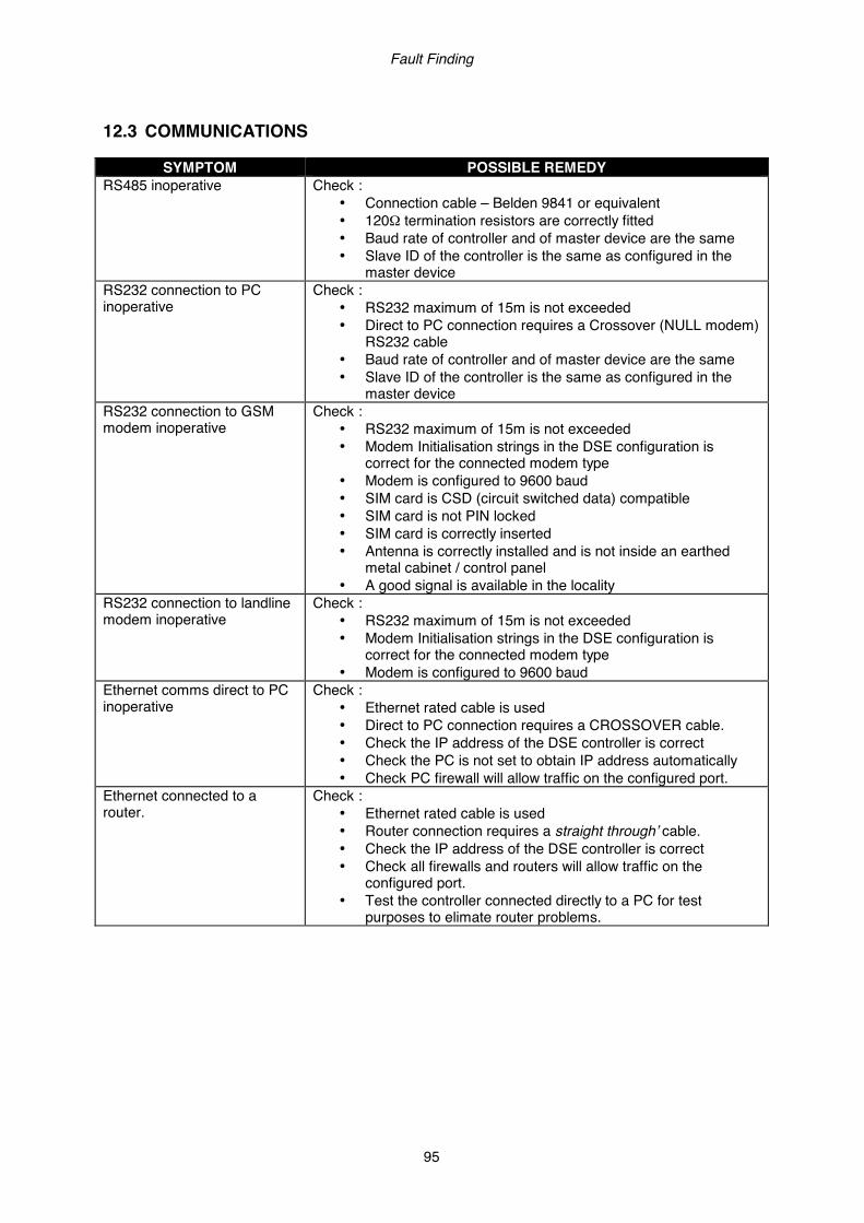
Fault Finding
95
12.3 COMMUNICATIONS
SYMPTOM POSSIBLE REMEDY RS485 inoperative Check :
• Connection cable – Belden 9841 or equivalent • 120Ω termination resistors are correctly fitted • Baud rate of controller and of master device are the same • Slave ID of the controller is the same as configured in the
master device RS232 connection to PC inoperative
Check : • RS232 maximum of 15m is not exceeded • Direct to PC connection requires a Crossover (NULL modem)
RS232 cable • Baud rate of controller and of master device are the same • Slave ID of the controller is the same as configured in the
master device RS232 connection to GSM modem inoperative
Check : • RS232 maximum of 15m is not exceeded • Modem Initialisation strings in the DSE configuration is
correct for the connected modem type • Modem is configured to 9600 baud • SIM card is CSD (circuit switched data) compatible • SIM card is not PIN locked • SIM card is correctly inserted • Antenna is correctly installed and is not inside an earthed
metal cabinet / control panel • A good signal is available in the locality
RS232 connection to landline modem inoperative
Check : • RS232 maximum of 15m is not exceeded • Modem Initialisation strings in the DSE configuration is
correct for the connected modem type • Modem is configured to 9600 baud
Ethernet comms direct to PC inoperative
Check : • Ethernet rated cable is used • Direct to PC connection requires a CROSSOVER cable. • Check the IP address of the DSE controller is correct • Check the PC is not set to obtain IP address automatically • Check PC firewall will allow traffic on the configured port.
Ethernet connected to a router.
Check : • Ethernet rated cable is used • Router connection requires a straight through’ cable. • Check the IP address of the DSE controller is correct • Check all firewalls and routers will allow traffic on the
configured port. • Test the controller connected directly to a PC for test
purposes to elimate router problems.
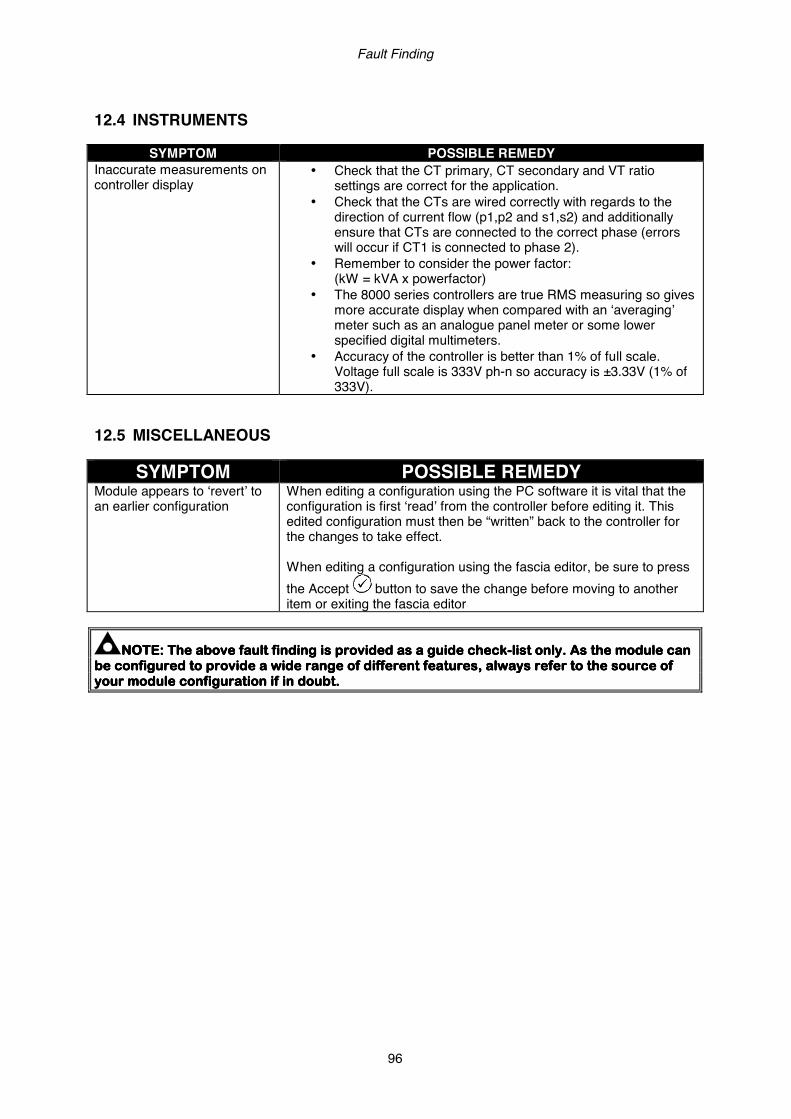
Fault Finding
96
12.4 INSTRUMENTS
SYMPTOM POSSIBLE REMEDY Inaccurate measurements on controller display
• Check that the CT primary, CT secondary and VT ratio settings are correct for the application.
• Check that the CTs are wired correctly with regards to the direction of current flow (p1,p2 and s1,s2) and additionally ensure that CTs are connected to the correct phase (errors will occur if CT1 is connected to phase 2).
• Remember to consider the power factor: (kW = kVA x powerfactor)
• The 8000 series controllers are true RMS measuring so gives more accurate display when compared with an ‘averaging’ meter such as an analogue panel meter or some lower specified digital multimeters.
• Accuracy of the controller is better than 1% of full scale. Voltage full scale is 333V ph-n so accuracy is ±3.33V (1% of 333V).
12.5 MISCELLANEOUS
SYMPTOM POSSIBLE REMEDY Module appears to ‘revert’ to an earlier configuration
When editing a configuration using the PC software it is vital that the configuration is first ‘read’ from the controller before editing it. This edited configuration must then be “written” back to the controller for the changes to take effect. When editing a configuration using the fascia editor, be sure to press the Accept button to save the change before moving to another item or exiting the fascia editor
NOTE:NOTE:NOTE:NOTE: The above The above The above The above fault findingfault findingfault findingfault finding is provided as a guide checkis provided as a guide checkis provided as a guide checkis provided as a guide check----list only. As the module can list only. As the module can list only. As the module can list only. As the module can be configured to be configured to be configured to be configured to provide a wide range of different features, always refer to the source of provide a wide range of different features, always refer to the source of provide a wide range of different features, always refer to the source of provide a wide range of different features, always refer to the source of your module configuration if in doubt.your module configuration if in doubt.your module configuration if in doubt.your module configuration if in doubt.

Commissioning and Fault Finding
97
13 DSE 4 STEPS TO SUCCESSFUL SYNCHRONISING Synchronising and load sharing is often considered to be a complex subject. In fact, it is very simple when broken down into smaller steps. After following the Commissioning section of this manual, the 4 Steps must be followed before any parallel operation is attempted. The following information is a short form guide only, intended as a memory jogger once the steps are fully understood. The full video presentation of the 4 Steps is available on the DSE website: www.deepseaplc.com. Registration on the website is required. This is free of charge, along with all other downloads. This page is also available as a training document (handout style) from DSE Part Number: 056-001 Four Steps to Synchronising – included on the DSE website. 13.1 CONTROL Check the control from DSE8x10 is working:
• Control of AVR • Control of Governor • Direction of Control
Failure of the above steps will result in poor control of the governor/AVR leading to problems during synchronising and/or load sharing if not corrected. 13.2 METERING Check the metering on the DSE8860 and DSE8x10(s) is working:
• CTs on the Right Phase • CTs in the Right Direction
Failure of the above steps will result in incorrect power factor and kW calculations leading to problems load sharing if not corrected. 13.3 COMMUNICATIONS Check the MSC link connected to the DSE8860 and DSE8x10(s) is working:
• All Modules Connected on the MSC Link • Re-Calibrate, Sync + Load Control, Multi-Set • Remove One MSC Plug
Failure of the above steps will result in the controllers being unable to communicate leading to problems during synchronising and/or load sharing if not corrected. 13.4 SYNC CHECKS Check each phase across the breakers controlled by the DSE8860 and DSE8x10(s) are wired correctly:
• Use the Built in Sync Scope to Determine Correct Phase Wiring • Phase Checks across the Breaker.
Failure of the above steps will result in serious damage to the system (breakers, bus bars, alternators, engines etc)
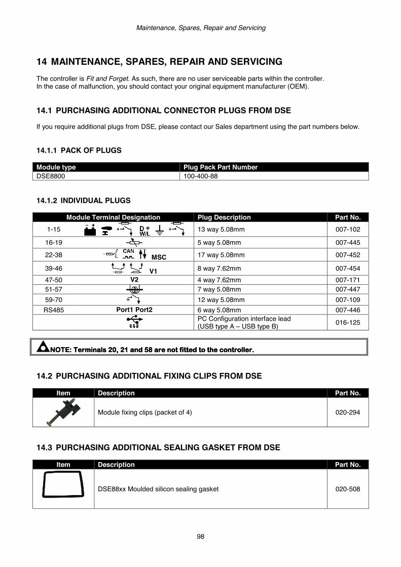
Maintenance, Spares, Repair and Servicing
98
14 MAINTENANCE, SPARES, REPAIR AND SERVICING The controller is Fit and Forget. As such, there are no user serviceable parts within the controller. In the case of malfunction, you should contact your original equipment manufacturer (OEM). 14.1 PURCHASING ADDITIONAL CONNECTOR PLUGS FROM DSE If you require additional plugs from DSE, please contact our Sales department using the part numbers below. 14.1.1 PACK OF PLUGS Module type Plug Pack Part Number DSE8800 100-400-88 14.1.2 INDIVIDUAL PLUGS
Module Terminal Designation Plug Description Part No. 1-15
13 way 5.08mm 007-102
16-19 5 way 5.08mm 007-445
22-38 MSC 17 way 5.08mm 007-452
39-46 V1 8 way 7.62mm 007-454 47-50 V2 4 way 7.62mm 007-171 51-57 7 way 5.08mm 007-447 59-70 12 way 5.08mm 007-109 RS485 Port1 Port2 6 way 5.08mm 007-446
PC Configuration interface lead (USB type A – USB type B) 016-125
NOTE:NOTE:NOTE:NOTE: Terminals 20, 21Terminals 20, 21Terminals 20, 21Terminals 20, 21 andandandand 58 are not fitted to58 are not fitted to58 are not fitted to58 are not fitted to the the the the controller.controller.controller.controller.
14.2 PURCHASING ADDITIONAL FIXING CLIPS FROM DSE
Item Description Part No.
Module fixing clips (packet of 4) 020-294
14.3 PURCHASING ADDITIONAL SEALING GASKET FROM DSE
Item Description Part No.
DSE88xx Moulded silicon sealing gasket 020-508

DSENet Expansion Modules
99
14.4 DSENET EXPANSION MODULES
NOTE:NOTE:NOTE:NOTE: A maximum of twenty (20) expansion modules can be connected to the DSENet®.A maximum of twenty (20) expansion modules can be connected to the DSENet®.A maximum of twenty (20) expansion modules can be connected to the DSENet®.A maximum of twenty (20) expansion modules can be connected to the DSENet®.
NOTE: NOTE: NOTE: NOTE: DSENet® utilises an RS485 connection. Using Belden 9841 (or equivalent) cable allows DSENet® utilises an RS485 connection. Using Belden 9841 (or equivalent) cable allows DSENet® utilises an RS485 connection. Using Belden 9841 (or equivalent) cable allows DSENet® utilises an RS485 connection. Using Belden 9841 (or equivalent) cable allows for the expansion cable to be extended to afor the expansion cable to be extended to afor the expansion cable to be extended to afor the expansion cable to be extended to a maximum of 1.2km.maximum of 1.2km.maximum of 1.2km.maximum of 1.2km. DSE Stock and supply DSE Stock and supply DSE Stock and supply DSE Stock and supply the the the the Belden 9841 cable. DSE Part Number 016Belden 9841 cable. DSE Part Number 016Belden 9841 cable. DSE Part Number 016Belden 9841 cable. DSE Part Number 016----030.030.030.030.
Item
Description
DSE Part Numbers Max No.
supported Model order
number Sales
literature Operator manual
Installation Instructions
4 Model DSE2130 input module provides additional analogue and digital inputs for use with the controller.
2130-001-00 055-060 057-082 053-033
4 Model DSE2131 Ratio-metric input expansion module provides additional restive, digital, 0-10V and 4-20ma inputs for use with the controller.
2131-001-00 055-115 057-139 053-125
4 Model DSE2133 RTD/Thermocouple input expansion module provides additional RTD and thermocouple inputs for use with the controller.
2133-001-00 055-114 057-140 053-126
4 Model DSE2152 Ratio-metric output expansion module provides additional 0-10V and 4-20ma outputs for use with the controller.
2152-001-00 055-112 057-141 053-134
10 Model DSE2157 expansion relay module provides eight additional voltage free relays for use with the controller
2157-001-00 055-061 057-083 053-034
10 Model DSE2548 expansion LED module provides additional LED indications, internal sounder and remote lamp test/alarm mute for use with the controller.
2548-001-00 055-062 057-084 053-032
Disposal & Warranty
100
15 WARRANTY DSE provides limited warranty to the equipment purchaser at the point of sale. For full details of any applicable warranty, you are referred to your original equipment supplier (OEM). 16 DISPOSAL 16.1 WEEE (WASTE ELECTRICAL AND ELECTRONIC EQUIPMENT) Directive 2002/96/EC If you use electrical and electronic equipment you must store, collect, treat, recycle and dispose of WEEE separately from your other waste. 16.2 ROHS (RESTRICTION OF HAZARDOUS SUBSTANCES) Directive 2002/95/EC: 2006 To remove specified hazardous substances (Lead, Mercury, Hexavalent Chromium, Cadmium, PBB & PBDE´s) Exemption Note: Category 9. (Monitoring & Control Instruments) as defined in Annex 1B of the WEEE directive will be exempt from the RoHS legislation. This was confirmed in the August 2005 UK´s Department of Trade and Industry RoHS REGULATIONS Guide (Para 11). Despite this exemption, DSE has been carefully removing all non RoHS compliant components from our supply chain and products. When this is completed, a Lead Free & RoHS compatible manufacturing process will be phased into DSE production. This process that is almost complete and is being phased through different product groups.

This Page Is Intentionally Left Blank.
101

This Page Is Intentionally Left Blank.
102
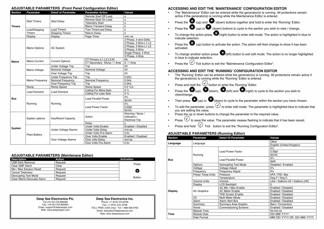
ACCESSING AND EDIT THE ‘MAINTENANCE’ CONFIGURATION EDITOR • The ‘Maintenance’ Editor can be entered while the generator(s) is running. All protections remain
active if the generator(s) is running while the Maintenance Editor is entered.
• Press the (up) and (down) buttons together and hold to enter the ‘Running’ Editor.
• Press the (up) or (down) buttons to cycle to the section you wish to view / change.
• To change the action press (right) button to enter edit mode. The action is highlighted in blue to indicate selection.
• Press the (up) button to activate the action. The action will then change to show it has been activated.
• To change another action press (left) button to exit edit mode. The action is no longer highlighted in blue to indicate selection.
• Press the Tick button to exit the “Maintenance Configuration Editor”.
ACCESSING AND EDIT THE ‘RUNNING’ CONFIGURATION EDITOR • The ‘Running’ Editor can be entered while the generator(s) is running. All protections remain active if
the generator(s) is running while the ‘Running’ Editor is entered.
• Press and hold the button to enter the ‘Running’ Editor.
• Press the (up), (down), (left) and (right) to cycle to the section you wish to view/change.
• Then press (up) or (down) to cycle to the parameter within the section you have chosen.
• To edit the parameter, press to enter edit mode. The parameter is highlighted blue to indicate that you are editing the value.
• Press the up or down buttons to change the parameter to the required value.
• Press to save the value. The parameter ceases flashing to indicate that it has been saved.
• Press and hold Tick button to exit the “Running Configuration Editor”. ADJUSTABLE PARAMETERS (Running Editor) Section Parameter Detail Of Parameter Values
Language Language Other English (United Kingdon)
Bus
Running Load Power Factor
0% 0.00pf 0kVAr
Load Parallel Power 0% 0kW
Options Decoupling Test Mode Disabled / Enabled Voltage Voltage Adjust 0% Frequency Frequency Adjust 0%
Display
Press/ Temp Units Pressure kPA / PSI / Bar Temperature Deg F / Deg C Volume Units Volume Litre / Gallons US / Gallons (UK) Display LCD Backlight 0
AC Graphics AC Min / Max Enable Enabled / Disabled AC Meter Enable Enabled / Disabled THD Screen Enable Enabled / Disabled
I/O Multi Meter Mode Enabled / Disabled Alarm Alarm Alert Box Enabled / Disabled Summary Summary Area Graphic Bars / Connectors Home Commissioning Screens Enabled / Disabled
Time Module Time hh:mm:ss Module Date DD/ MM/ YYYY Date Format MM/ DD/ YYYY OR DD/ MM/ YYYY
Deep Sea Electronics Plc. Tel:+44 (0)1723 890099
Fax: +44 (0)1723 893303 Email: [email protected]
Web: www.deepseaplc.com
Deep Sea Electronics Inc. Phone: +1 (815) 316-8706 Fax: +1 (815) 316- 8708
TOLL FREE (USA only) : Tel: 1 866 636 9703 Email: [email protected]
Web: www.deepseausa.com
ADJUSTABLE PARAMETERS (Front Panel Configuration Editor) Section Parameter Detail of Parameter Parameter Action Values
Timers
Start Timers Start Delay
Remote Start Off Load s Remote Start On Load s Telemetry Start s Mains Transient Delay s
Load/Stopping Timers
Load Timers Tran Time/Load Delay s Stopping Timers Return Delay s
Display Display Page Timer mm: ss
Mains
Mains Options AC System
3 Phase, 4 wire Delta 2 Phase, 3 Wire L1-L3 2 Phase, 3 Wire L1-L2 3 Phase, 3 Wire Single Phase, 2 Wire 3 Phase, 4 Wire
Mains Current Current Options CT Primary (L1,L2,L3,N) 0A CT Secondary 5Amp / 1 Amp 5 / 1 Amp
Mains Voltage Under Voltage Trip Trip 0V Nominal Voltage Nominal Voltage 0V Over Voltage Trip Trip 0V
Mains Frequency Under Frequency Trip Trip 0.0Hz Nominal Frequency Nominal Frequency 0.0Hz Over Frequency Trip Trip 0.0Hz
Bus
Ramp Ramp Speed Ramp Speed 0.0 %/s
Load Demand Load Demand Calling For More Sets 0 % Calling For Less Sets 0 %
Running Running
Load Parallel Power 0% 0kVAr
Load Power Factor 0% 0.00pf 0kVAr
System
System options Insufficient Capacity Action Warning / None / Indication / Electrical Trip
Delay s
Plant Battery
Under Voltage Alarms Under Volts Enable Enabled / Disabled Under Volts Delay mm:ss Under Volts Pre-Alarm 0.0v
Over Voltage Alarms Over Volts Enable Enabled / Disabled Over volts Delay mm:ss Over Volts Pre-Alarm 0.0v
ADJUSTABLE PARAMETERS (Maintenace Editor) Description Action Activation USB Stick Removal Request Press
Button
Clear AMF Alarm Clear Min / Max Session Reset Request Cancel Telemetry Request Decoupling Test Mode Request Clear Mains Decouple Alarm Request