t lucid - yarracity.vic.gov.au · 3.7 intercom 11 3.8 access ... 13489-005 'lucid 3 a consui...
TRANSCRIPT

LUCID CONSULTING AUSTRALIA
t
RESIDENTIAL DEVELOPMENT 195 LENNOX STREET, RICHMOND Project No: LCE13489-005
Building Services Return Brief
15 December 2017

195 LENNOX ST, RICHMOND BUILDING ENGINEERING SERVICES RETURN BRIEF
TABLE OF CONTENTS
1. GENERAL 4
1.1 Basis of Brief 4
1.2 Building Description 4
1.3 Schedule of Authorities 4
2. MECHANICAL SERVICES 5
2.1 General 5
2.2 Design Criteria 5
2.3 Basement Car Parking Levels 6
2.4 Air Conditioning - Apartment Levels 7
2.5 Exhaust System - Apartments available 7
2.6 Fire & Life Safety Systems 7
2.7 Gas Fireplaces 7
Client Comments - Mechanical Services 8
3. ELECTRICAL SERVICES 9
3.1 General 9
3.2 Electrical Infrastructure 9
3.3 Electrical Metering 10
3.4 General Power 10
3.5 Communications 10
3.6 MATV/Foxtel 10
3.7 Intercom 11
3.8 Access Control 12
3.9 Intruder Detection 12
3.10 CCTV 12
3.11 Home Automation 13
3.12 Lighting 13
3.13 Emergency and Escape Lighting 14
3.14 General Inclusions 15
3.15 Solar PV System 15
3.16 Exclusions 15
Client Comments - Electrical Services 16
4. HYDRAULIC SERVICES 17
4.1 General 17
4.2 Hydraulic I nfrastructure 17
4.3 Services Metering / Isolation 17
4.4 Domestic Hot Water Service 18
13489-005 2
■LUCID 'Ir

195 LENNOX ST, RICHMOND BUILDING ENGINEERING SERVICES RETURN BRIEF
4.5 Stormwater Collection / Rainwater Reuse 18
4.6 Exclusions 18
Client Comments — Hydraulic Services 20
5. FIRE SERVICES 21
5.1 General 21
5.2 Fire Water Supply 21
5.3 Fire Hydrant System 21
5.4 Automatic Fire Sprinkler System 21
5.5 Portable Fire Extinguishers 21
5.6 Fire Hose Reel System 21
5.7 Smoke Detection and Alarm System 22
5.8 Fire engineering requirements 22
Client Comments — Fire Services 23
6. VERTICAL TRANSPORTATION SERVICES 24
6.1 Proposed Design 24
6.2 Design Details 24
6.3 Included Works 24
6.4 Excluded Works 25
6.5 Standard Requirements 25
Client Comments — Vertical Transportation Services 26
13489-005 3 'LUCID
A
CONSUI TM; AMTRAI IA

195 LENNOX ST, RICHMOND BUILDING ENGINEERING SERVICES RETURN BRIEF
1. GENERAL
1.1 Basis of Brief
This brief has been developed to demonstrate our understanding of the overall services scope of
works, and requirements.
The intent of the document is that it be reviewed by the design team and project stakeholders, with
any comments to be provided back for inclusion, and to finalise the scope of works based on the
architectural drawings.
1.2 Building Description
The building comprises of 3 basement level carparks server by 2No car lifts, the residential levels
comprise of 2No towers, the Lennox St tower is 5 levels including ground and the rear tower is 12
stories including ground, with total apartment numbers as below:
• 51 carparks
• 28 apartments
The effective height of the building is approximately 38 metres, and falls within the following National
Construction Code (NCC) classifications:
■ Apartments — Class 2
■ Carparks — Class 7a
1.3 Schedule of Authorities
The following presents a schedule of all the Authorities applicable to this site:-
Electrical Citipower
Copper Telecommunications Telstra
Fibre Optic Telecommunications NBN Co
Water/Sewer City West Water
Gas APA Group
Fire Services Metropolitan Fire Brigade
13489-005 1111
4
LUCilD
I
195 LENNOX ST, RICHMOND BUILDING ENGINEERING SERVICES RETURN BRIEF
2. MECHANICAL SERVICES
2.1 General
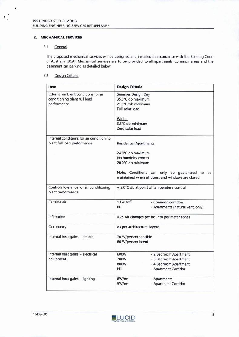
The proposed mechanical services will be designed and installed in accordance with the Building Code of Australia (BCA). Mechanical services are to be provided to all apartments, common areas and the basement car parking as detailed below.
2.2 Design Criteria
Item Design Criteria
External ambient conditions for air conditioning plant full load performance
Summer Design Day 35.0°C db maximum 21.0°C wb maximum Full solar load
Winter 3.5°C db minimum Zero solar load
Internal conditions for air conditioning plant full load performance Residential Apartments
be
24.0°C db maximum No humidity control 20.0°C db minimum
Note: Conditions can only be guaranteed to maintained when all doors and windows are closed
Controls tolerance for air conditioning plant performance
± 2.0°C db at point of temperature control
Outside air 1 Ifs /m2 - Common corridors Nil - Apartments (natural vent. only)
Infiltration 0.25 Air changes per hour to perimeter zones
Occupancy As per architectural layout
Internal heat gains — people 70 W/person sensible 60 W/person latent
Internal heat gains — electrical equipment
600W - 2 Bedroom Apartment 700W - 3 Bedroom Apartment 800W - 4 Bedroom Apartment Nil - Apartment Corridor
Internal heat gains — lighting 8W/m2 - Apartments 5W/m2 - Apartment Corridor
13489-005 "'LUCID
•

195 LENNOX ST, RICHMOND BUILDING ENGINEERING SERVICES RETURN BRIEF
Item Design Criteria
Base Building General & Toilet Exhaust 5 L/s/m2 - Bin Rooms
10 L/s/m2 - Common toilets
Toilet & Laundry Exhaust - Apartments 50 Lis - Apartment toilet and shower
50 L/s - Apartment laundry
80 L/s - Apartment combined laundry & toilet
Kitchen Exhaust - Apartments 80 Lis - Per kitchen rangehood
Proprietary range hood exhaust complete with booster
fans as required. Provided by others.
Carpark Exhaust In accordance with AS1668.2 (2012).
Controls Basement Carparks
Exhaust flow rate to modulate via variable speed drive
according to carbon monoxide levels. Control and
monitoring via CO sensors.
Residential Apartments
Apartment air conditioning to be controlled by a
proprietary wall mounted remote control panel.
Apartment toilet exhaust to incorporate into the light
switch for the toilet. Exhaust fan to have a run on timer
incorporated to run the fan for 10 min (adjustable) after
light has been switched off.
Range hood booster fans to be interlocked with the
proprietary range hood.
2.3 Basement Car Parking Levels
The basement levels shall be served by a central car park exhaust and supply air system in accordance
with AS1668.2 (2012). Exhaust and supply air ductwork shall be mounted at high level and shall
connect to carpark mounted in-line fans complete with ground floor intake planter box intake and roof
top discharge for larger tower.
The design shall incorporate column mounted carbon monoxide sensors to control exhaust and supply
air fan speed according to contaminate levels.
Supply air is also introduced via mechanical means which provides make-up air to the carpark exhaust
system. The net pressure within the basement is negative compared to the adjacent areas to prevent
vehicle exhaust fumes from spreading to other occupied levels.
13489-005 itapo 6
•

PrEIAIK 14
195 LENNOX ST, RICHMOND BUILDING ENGINEERING SERVICES RETURN BRIEF
•
2.4 Air Conditioning — Apartment Levels
Fully ducted, air cooled, reverse cycle split system with zone control
This Option provides a premium solution and comprises a fully ducted, reverse cycle, inverter driven
split system with direct cooling / heating to each room via in-ceiling ductwork. The system shall
incorporate 'zone control' such that the various spaces can be switched and control depending on
occupancy and preference. The outdoor unit will be located at either roof level or plant deck which is
to be at least 90% free area. The location will also depend on the refrigeration pipework lengths. The
air conditioning control shall be via a wall mounted, wired, LCD control panel in each room with one master control panel able to control all units.
2.5 Exhaust System — Apartments available
The apartments shall be provided with bathroom exhaust systems, laundry exhaust system and kitchen
range hood exhaust systems. The bathroom exhaust system will incorporate an in-line fan, ductwork
and controlled via the lights with 10 minute run on timer incorporated (adjustable) to the exhaust fan.
(provided by the electrical services trade). Kitchen range hoods will be provided with ductwork), and
inline fans in instances where the range hood will not have sufficient pressure to exhaust the air
adequately. Both the bathroom exhaust, laundry exhaust and kitchen exhaust will discharge via louvres
to the facade to the coordinated location with the architect. There will be generally three separate ducts, one for each of the bathroom exhausts, the laundry exhaust, and the kitchen range hood.
2.6 Fire & Life Safety Systems
The car park exhaust fans will incorporate interface with the Fire Indicator Panel (FIP) complete with
rotary switches for Fire Brigade override as required.
2.7 Gas Fireplaces
All gas fire places to be of the complete sealed (Direct Vent) type to ensure that permanent make up to
the space is avoided. These are the most efficient types of systems and also will not affect the overall
NatHERS rating for each apartment. The above system will not work for open fire places further
ventilation systems and permanent openings will be required which will have a negative impact on the
apartment performance.
13489-005

Client Comments — Mechanical Services
195 LENNOX ST, RICHMOND
BUILDING ENGINEERING SERVICES RETURN BRIEF
13489-005 8
■LUCID

195 LENNOX ST, RICHMOND BUILDING ENGINEERING SERVICES RETURN BRIEF
3. ELECTRICAL SERVICES
3.1 General
The building electrical services will be designed and installed in accordance with the Building Code of Australia (BCA) and relevant electrical design and safety standards including AS 3000, AS 3008, AS1680 and AS 2293.
The major electrical services will include CitiPower works an installation of an onsite indoor substation, a low voltage supply from the substation, provision of a main switchboard (incorporating utility metering and common area power systems), distribution boards and power reticulation systems to individual apartment load centres.
Lighting and general power systems will be provided to all apartments and common areas. Communications infrastructure, access control system, MATV/Pay TV and an audio/video intercom system will also be included within the building.
Communications infrastructure will be designed to accommodate NBN Co infrastructure throughout the complex and to each apartments. An application to NBN will be made to ensure the rollout of fibre to the property meets the project's deliverables.
Building, access control systems, car park lighting system and exit and emergency lighting to code requirements also form part of the design.
3.2 Electrical Infrastructure
The major electrical infrastructure supplying the site is still pending details to be provided by CitiPower, however in general it will include:
■ The establishment of a new on site indoor substation from CitiPower's network.
■ Site main switchboard, including submain cabling rising to individual apartment load centres.
■ Polycarbonate load centres to each apartment for reticulation of general power and lighting sub- circuits within each living unit (also containing local lighting control system equipment).
Example Schneider recessed 'Mini Pragma' Load Centre, plain or translucent door available
(270mm W x 478mm H x 80mm D, with 18mm protrusion from wall)
• Surge protection to the site main switchboard.
•
13489-005 9 ■LUCID

195 LENNOX ST, RICHMOND BUILDING ENGINEERING SERVICES RETURN BRIEF
3.3 Electrical Metering
It is anticipated that the electrical metering philosophy will be provided as follows:
Authority meter provided for each apartment,
Bulk CT meters provided for the common areas (body corporate),
Main gate meter on the main switchboard may be considered if the development is to head down
an Embedded Network path (Client to advise).
3.4 General Power
Power outlets throughout apartments shall generally consist of "Clipsal Saturn Zen" series outlets.
Clipsal Saturn Zen
General power will be provided throughout the common area to allow for cleaners points.
3.5 Communications
The proposed building will be designed to accommodate NBN throughout the development including
main hubs within the Main Communication cupboard in the basement and all necessary FDT and NTD
NBN equipment.
The minimum allowances for communication outlets as follows:-
• 2 communications outlet per bedroom or in study
■ 4 communications outlet per living room adjacent MATV/Foxtel outlet location
All communications outlets will be wired back to the NTD location in the relevant apartment wardrobe
mounted on the side facing wall of the wardrobe with the hanging rail cut short by 200mm.
3.6 MATV/Foxtel
Provision of MATV (Digital Free to Air) and Satellite Foxtel to each apartment:-
• 1 MATV/Foxtel point in the living room and all bedrooms.
13489-005 10 IILTY P

195 LENNOX ST, RICHMOND
BUILDING ENGINEERING SERVICES RETURN BRIEF
All communications (including MAW) outlet face plates will be selected to match adjacent power
outlets.
Matchmaster 01MM Series MAN Antenna
Foxtel Satellite Dish
3.7 Intercom
Provision of colour audio-visual intercom system to each apartment, with entrance station located at
building/apartment entrances.
Per voice
eiekta elekta steel
Poiecer
Urmet Modo Series Urmet Elektra Series (Apartments) (Entrance)
11 13489-005 •LUCID

195 LENNOX ST, RICHMOND BUILDING ENGINEERING SERVICES RETURN BRIEF
3.8 Access Control
Building security system will comprise a basic electronic access control system only. The system will
include proximity tag readers and doors sets on common area doors and lifts and interfaced with
intercom systems, carpark door and common area lighting. Access to all doors will by an RFID key Fob.
Carpark entry via the automated carpark lifts shall be via key fob.
No electronic access control will be provided to individual apartment entry doors.
Typical RFID Key Fob
3.9 Intruder Detection
Apartments shall be provided with a standalone alarm and intruder detection system which shall
consist of PIR movement sensors. A key pad at the entry of the apartment shall also be provided to
allow for arming and disarming the apartment's alarm system.
3.10 CCTV
It is proposed to provide a CCTV to cover building entrances, foyers, lifts, carpark and common areas
including amenity areas, and shall generally have the following characteristics:
■ Fixed dome cameras to nominated areas.
■ Digital Video Recording (DVR) with 4 weeks storage.
• Graphical user interface capable of external access.
■ Integration with access control system for face capture on card read.
0•01 ,..,,,,,,A 1 •
Samsung Dome CCTV Camera
4
13489-005 12
■LcJCID

195 LENNOX ST, RICHMOND BUILDING ENGINEERING SERVICES RETURN BRIEF
3.11 Home Automation
We anticipate that some form of home automation will be expected, and propose to provide appropriate power & communications provisions within each apartment to allow the integration of a home automation system.
The requirement for seamless integration of each of the building subsystems into a home automation system necessitates that the specific system selection and power & communications provisions be developed through the course of the design.
3.12 fighting
Common Area
All lighting systems will be designed and installed to comply with the BCA's Section J on energy efficiency. This includes the use of energy efficient luminaires and the required automated control equipment. In general, lighting shall be provided as follows:
■ Stairwell and carpark lighting will generally consist of surface mounted LED fittings.
■ Lighting to the internal common areas, lobby etc. will be further refined during the design development phase to incorporate a more decorative treatment in comparison to the other areas.
Control of lighting throughout the common areas will be undertaken with a programmable lighting control system, which includes movement controlled switching.
Apartments
Lighting to the apartments is proposed to be provided as follows:
■ Lighting to each apartment will utilise high quality LED luminaires. Final selections will be undertaken based on the final apartment layouts and ceiling types. LED strip (concealed into overhead joinery) and pendant luminaires would also be suggested to kitchen benches (the need for either dependent on where overhead cupboards are located).
■ Weatherproof light fittings will be provided to external living unit courtyard and balcony areas, intended as low-level ambient lighting for these spaces.
■ Lighting control shall be via a localised lighting control system utilising DALI technology.
- It is proposed to provide a Clipsal DALI system, which would allow for preprograming of the units off site, and ease of install on site.
- A lighting control panel, such as the Clipsal eDLT (DALI lighting control incorporated via a C- Bus/DALI gateway), would be located in the living area. The unit will provide general lighting switching and dimming control, and also allow for on and off (switching) control of the air-conditioning systems.
13489-005 13 ■":1NS, I imp';

195 LENNOX ST, RICHMOND BUILDING ENGINEERING SERVICES RETURN BRIEF
Clipsal eDLT range
Other areas will use Clipsal DALI wall switches, and allow for staged dimming of lighting
within each room (either by pre-programmed dimming levels assigned to particular switches,
or press-and-hold to dim).
Clipsal Saturn Zen Wall Switch Range
DALI control gear will allow for all lighting within the apartments to be connected to a single
power circuit, and with only minor programming done on site, create completely
customisable lighting scene control and switching entirely through programming. The
lighting can also easily be reprogrammed in the future as required (via a competent
integrator). This approach minimises the amount of electrical labour and cabling in
comparison to a conventional install, and removes the need for hard-wired modifications in
the future.
3.13 Emergency and Escape Lighting
LED exit and emergency lighting to be provided throughout the building including central test facilities
provided within common area distribution board.
Carpark areas will consist of general exit luminaires, and internal areas will consist of blade type exit
luminaires. Weatherproof exit luminaires will be provided to any external areas where exposed to direct
weather.
13489-005 14
!Luc,' p

Blade Exit Luminaires
• ■
Emergency Luminaires
General Exit Luminaires
Weatherproof Exit Luminaires
195 LENNOX ST, RICHMOND BUILDING ENGINEERING SERVICES RETURN BRIEF
3.14 General Inclusions
■ Apartments to incorporate power and/or communications provisions for.
- power supplies for motorised blinds
- heated towel rails.
3.15 Solar PV System
A solar photovoltaic system shall be provided on the buildings roof to offset building emissions and
provide solar energy back to communal lighting and general power requirement. The solar PV system
shall be grid connection from the electrical distribution system and be of capacity 9.9kW comprising of
solar panels, invertor, bi-directional metering and all associated equipment and cabling.
3.16 Exclusions
Car space monitoring and counting systems.
Active networking equipment, telephone systems etc.
Wireless networking equipment.
■ Uninterruptible power supplies
Intruder detection systems.
Traffic management systems (lights) if required.
13489-005 15 IIILUC I D coNsU!TI 4lL'illl/s1 in

195 LENNOX ST, RICHMOND
BUILDING ENGINEERING SERVICES RETURN BRIEF
Client Comments — Electrical Services
13489-005 Il
16
LUCID CONSUL

195 LENNOX ST, RICHMOND BUILDING ENGINEERING SERVICES RETURN BRIEF
4. HYDRAULIC SERVICES
4.1 General
The building's hydraulic services will be designed and installed in accordance with the National Construction Code of Australia (NCC), Victorian Building Authority (VBA) and relevant Australian Standards including AS/NZS 3500 & AS/NZS 5601.
4.2 Hydraulic Infrastructure
The capacity of the existing sewer and water infrastructure in the streets surrounding the proposed development has yet to be confirmed by City West Water. A Preliminary Servicing Advice (PSA) request has been lodged and once received the advice will stipulate whether any of the authority assets will require an upgrade to cater for the increased demand as a result of the proposed development.
APA Gas to confirm whether the development has low pressure natural gas infrastructure and whether the gas supply off Lennox Street will have sufficient capacity to service the proposed development. There is currently a 150mm gas main in Lennox Street and assumed the required gas pressure for this development shall consists of 1.1-2.75kPa to be extended to site if required.
A summary of the hydraulic infrastructure within the building is as follows:-
The establishment of a new 100mm fire service magnetic flow meter assembly & 50mm general domestic cold water meter assembly with new 100mm dual supply tapping to development where the main meter assembly is located on ground level which will required new water extension down the brick paved road subject to City West Water approval.
Gas meter enclosure located down the brick paved road of the property consisting of the following:-
- Gas meter 1 - Central hot water service / apartment cooktops/ Gas fire places
- Gas meter 2 - Pool heating equipment
The gas meter enclosure has been sized according to the above gas loads only.
Rainwater storage tank with a total capacity of 25kL is to be provided below ground within the basement. Rainwater is to be reticulated to all apartments and be used for toilet flushing only.
No allowance has been made to provide rainwater for irrigation of landscaped areas.
No grease interceptor trap is to be provided for this development.
4.3 Services Metering / Isolation
It is anticipated that the water metering philosophy will be provided as follows:
050mm authority cold water meter.
1 x common area water meter to be provided for bin room wash down point and any base building amenities.
Apartment levels metering/isolation as follows: -
- 11 x 020mm pulse output remote read cold water meter (1 per apartment) located within service riser cupboard
13489-005 17 ■LUCID

195 LENNOX ST, RICHMOND BUILDING ENGINEERING SERVICES RETURN BRIEF
- x 020mm pulse output remote read hot water meter per apartment located within
service riser cupboard
- 1 x High pressure natural gas isolation valve per apartment level located within
central fire rated enclosure.
- 1 x high pressure natural gas isolation valve per apartment located within ceiling
space of the corridor directly in front of the associated apartment.
• 1 x 050mm cold water meter to inlet of central hot water service.
■ 1 x natural gas meter to inlet of central hot water service.
■ 1 x 025mm water meter to potable water back up supply to rainwater service complete with
backflow prevention device.
■ 1 x 025mm water meter for bin wash room area.
4.4 Domestic Hot Water Service
There shall be one domestic hot water system for this development.
The development shall be produced by a central gas boosted continuous hot water system located on
the roof top plant area.
Hot water system shall consist of the domestic hot water reticulating with a flow and return pipework
system serving the apartment levels. The hot water return line will be fitted with automatic balancing
valves where required which will monitor and regulate the flow of hot water back to the hot water
system.
Thermostatic Tempering Valves (set at 50°C) will be used within all apartments to temper the water
and any DDA (disabled) toilets shall require Thermostatic Mixing Valves (set at 43°C).
4.5 Stormwater Collection / Rainwater Reuse
The rainwater will be captured via multiple box gutters and reticulate through conventional downpipes
to the rainwater storage tanks located below ground within the basement.
Overflow from the storage tanks along with rainwater captured from balconies or terrace areas will be
discharged directly into the council stormwater system. The final connection to the legal point of
discharge will be included within the civil documentation.
Rainwater is to be utilised for toilet flushing only. To ensure that there is a constant water supply
during periods of low rainfall, a mains water back-up water supply shall be connected via an adjacent
isolation valve and solenoid valve assembly. When there is rainwater in the storage tank, the float
switch shall be raised, which will signal the pump system controller that rainwater is available for water
re-use, and the Town mains solenoid valve shall be closed. When there is a pressure drop in the
system, the pressure switch shall signal the pump to start operation. A solenoid valve (normally open, energized to close) shall be connected to the town mains supply, and shall open to service water re-
use on low water tank level, as signalled by float switch, or if the pump/power fails.
4.6 Exclusions
■ Stormwater trench grate at both carpark entrance and drainage system (by Civil)
• Stormwater ejector pump station within the basement (by Civil)
13489-005 18
■LUCID
195 LENNOX ST, RICHMOND BUILDING ENGINEERING SERVICES RETURN BRIEF
■ Sub-soil drainage systems (by Civil)
■ Sanitary Fixtures and Fittings (to be specified by the architect)
13489-005 19
■LUCID

195 LENNOX ST, RICHMOND
BUILDING ENGINEERING SERVICES RETURN BRIEF
Client Comments — Hydraulic Services
13489-005 III
20 LUCID
Tir1 MY:JR/NI IA

195 LENNOX ST, RICHMOND
BUILDING ENGINEERING SERVICES RETURN BRIEF
S. FIRE SERVICES
5.1 General
The building fire services will generally be designed and installed in accordance with the Deemed to
Satisfy provisions of the National Construction Code (NCC). It is our understanding that a fire
engineering solution will likely be required in order to permit the building to deviate from the NCC's
prescriptive requirements. It is expected that the alternative building solutions may affect the outcome
of proposed fire and life safety systems.
5.2 Fire Water Supply
The fire water supply is proposed to serve an internal fire hydrant system via the existing Lennox St
town's main water supply.
Town's main water supply characteristics have been confirmed using water authority 95% pressure and
flow figures. The available town mains flow is considered adequate to supply the internal hydrant
system, however a pump system will be required in order to provide compliant hydrant pressure to the
most remote hydrant.
5.3 Fire Hydrant System
The NCC requires that buildings with a total floor area of greater than 500m2 be provided with fire
hydrant protection in accordance with AS 2419.1.
It is proposed that an internal hydrant system will be used in order to achieve fire hydrant coverage to
all areas of the building. Internal hydrants will be required within 4m of the exit (stair landing) on each
level including ground floor.
5.4 Automatic Fire Sprinkler System
The NCC requires an automatic fire sprinkler system to be installed throughout as the building exceeds
25m in effective height.
It is proposed to supply the sprinkler system off the hydrant ring main and reticulate the sprinkler
system water supply in accordance with AS2118.6 combined system requirements.
Sprinkler heads throughout shall be fully flush mounted type.
5.5 Portable Fire Extinguishers
Portable fire extinguishers are proposed to be provided within 10m of all SOU doors to ensure
compliance with NCC and in accordance with ASS 2444 and MFB guideline GL-16.
5.6 Fire Hose Reel System
The NCC states a fire hose reel system must be provided where internal hydrants are installed, to serve
any fire compartment with a floor area greater than 500m2.
It is proposed that fire hose reels be provided within the basement carpark of the building.
Fire hose reels are not required throughout residential levels as noted within NCC 2016.
13489-005 21
■
CONSLX '*KG AUSTAAI

•. •
195 LENNOX ST, RICHMOND BUILDING ENGINEERING SERVICES RETURN BRIEF
5.7 Smoke Detection and Alarm System
It is proposed to install an automatic smoke detection and alarm system throughout the building as
required by the NCC. This will also facilitate the requirement for a fire indicator panel within the
heritage building common area.
It is proposed that all common spaces will be provided with smoke detection and occupant warning in
accordance with NCC and AS 1670.1 requirements.
Within all SOU's smoke alarms in accordance with AS 3786 shall be installed. Interconnection of both
systems is subject to fire engineering requirements.
5.8 Fire engineering requirements
Given the nature of the building, it is likely that the development will be subject to fire engineering
alternative solutions.
It is expected that the alternative building solutions may affect the outcome of proposed fire and life
safety systems, however proposed alternative solutions have not been confirmed at the time of
documenting this brief.
13489-005
■LUCID 22

Client Comments - Fire Services
195 LENNOX ST, RICHMOND BUILDING ENGINEERING SERVICES RETURN BRIEF
23 MLUC I RA 13489-005

195 LENNOX ST, RICHMOND BUILDING ENGINEERING SERVICES RETURN BRIEF
6. VERTICAL TRANSPORTATION SERVICES
6.1 Proposed Design
The proposed vertical transportation arrangement for the mixed-use development is to incorporate one (1), 1600 kg/21 Passenger machine room-less passenger lift to serve the western tower and two (2), 1275 kg/17 passenger lifts to serve the eastern tower to satisfy traffic management throughout the building.
6.2 Design Details
The following systems and services shall generally be included and form a part of the Vertical Transportation scope of works:
6.3 Included Works
■ Two (2) off 17 passenger, 1.6 m/s, machine room less passenger lift to serve the apartment levels, in the eastern tower in accordance with AS 1735 and BCA
■ One (1) off 21 passenger, 1.0 m/s machine room less passenger lift to serve the apartment levels, in the western tower in accordance with AS 1735 and BCA
• Lift equipment complete with all machinery, structural steel support beams and roping, governors, rope guards brake release and winding devices.
• Landing equipment including landing frames, sills and sill supports, lift well flushing, landing doors door support and locks, door closers, directional indicators and landing call buttons. Allow for sill to bridge gap with adjacent concrete flooring.
■ Lift well equipment including guide rails, trimmer beams and fixings, counterweights and guards, guide shoes, pit access, screens to trailing cables and counterweights, ropes and fittings, buffers and supports, access ladders and any other ancillary items required to complete the installation.
■ Lift cars and associated equipment including platforms, car frames, safety gear, car enclosures, ventilation systems, doors, hangers and tracks, sills, operating panels and position indicators.
• Controls associated with each lift installation including supervisory control systems, speed controls, lift controllers, levelling and floor finding systems, pit stop switches, fire service recall switches and power safety cut-off switches.
■ Battery back-up system for automatic emergency lowering and door opening operation, to each Lift.
• Lift installation in accordance with Australian Standard AS 1735 — Lift Code with full compliance with AS1735 Part 12 — Facilities for Persons with Disabilities.
■ Lift car internal finishes as detailed by the architect.
■ Permanent guards and handrails required by Department of Administrative and Information Services — Workplace Services and AS 1735.
■ Noise and vibration control associated with lit installation.
■ Installation of card readers (supplied by Access Control System Trade) within each lift car and installation of associated trailing cable in lift shaft terminating at associated lift control panel.
24 13489-005 ULUCID

195 LENNOX ST, RICHMOND BUILDING ENGINEERING SERVICES RETURN BRIEF
■ Testing and commissioning of lift installation.
■ 12 months registration of lift in the name of the Proprietor.
Maintenance and servicing, warranty defects liability of 12 months from date of practical completion of lift installation.
■ Installation drawings and operating manuals.
6.4 Excluded Works
Construction of lift shaft including provision of lifting beam at top of lift shaft
Provision of cut-outs (rough openings) at each landing
Door frame reveals to architectural details
Dry sump in lift pit
Installation and allowance for terminals of dedicated power supply and telephone line
Design Responsibility The Contractor shall be responsible for detailed design of the lift installation in accordance with the performance requirements set out herein and in accordance with the details indicated on the architectural drawings.
6.5 Standard Requirements
The Vertical Transportation installation shall conform to the requirements of the WorkCover Authority, Australian Standards, BCA and other applicable Authority requirements. In particular vertical transportation system shall comply with current editions including addenda of
AS 1735 Parts 1 & 2 — Lifts, Escalators and Moving Walks
• Full compliance of installations with part 12 of AS 1735 with regard to operation and access for persons with disabilities
• AS 3000 - SAA Wiring Rules and requirements of all regulatory authorities having jurisdiction over the work.
• Building Code of Australia
13489-005 25
CONSO' TIM; At_.,STR..1. In
195 LENNOX ST, RICHMOND
BUILDING ENGINEERING SERVICES RETURN BRIEF
Client Comments — Vertical Transportation Services
13489-005 26
TING AUSTRAI IA